April 2008, Rev.1, 6/11 ©2008 - 2011 Fluke Corporation. All rights reserved. Specifications subject to change without notice. 1 113 Electrical Multimeter Calibration Information Introduction Warning To avoid electric shock or injury, do not perform the performance tests or calibration adjustment procedures unless qualified to do so. The information provided in this document is for the use of qualified personnel only. The 113 Calibration Information provides the information necessary to adjust and verify the performance of the Fluke Model 113 Electrical Multimeter (hereafter known as the Meter). The following information is included in this document: • Safety Information and International Electrical Symbols (page 2) • Specifications (page 3) • Replacing the Battery (page 5) • Cleaning (page 5) • Performance Tests (page 5) • Calibration Adjustment (page 7) • Replacement Parts and Accessories (page 11) • Complete Warranty (page 13) See the 113 Users Manual for complete operating instructions. Contacting Fluke To contact Fluke, call one of the following telephone numbers: USA: 1-888-99-FLUKE (1-888-993-5853) Canada: 1-800-36-FLUKE (1-800-363-5853) Europe: +31 402-675-200 Japan: +81-3-3434-0181 Singapore: +65-738-5655 Anywhere in the world: +1-425-446-5500 Or, visit Fluke's Web site at www.fluke.com. To register your product, visit http://register.fluke.com

Welcome message from author
This document is posted to help you gain knowledge. Please leave a comment to let me know what you think about it! Share it to your friends and learn new things together.
Transcript

April 2008, Rev.1, 6/11 ©2008 - 2011 Fluke Corporation. All rights reserved. Specifications subject to change without notice. 1
113 Electrical Multimeter
Calibration Information
Introduction Warning
To avoid electric shock or injury, do not perform the performance tests or calibration adjustment procedures unless qualified to do so. The information provided in this document is for the use of qualified personnel only.
The 113 Calibration Information provides the information necessary to adjust and verify the performance of the Fluke Model 113 Electrical Multimeter (hereafter known as the Meter).
The following information is included in this document:
• Safety Information and International Electrical Symbols (page 2) • Specifications (page 3) • Replacing the Battery (page 5) • Cleaning (page 5) • Performance Tests (page 5) • Calibration Adjustment (page 7) • Replacement Parts and Accessories (page 11) • Complete Warranty (page 13)
See the 113 Users Manual for complete operating instructions.
Contacting Fluke To contact Fluke, call one of the following telephone numbers:
USA: 1-888-99-FLUKE (1-888-993-5853) Canada: 1-800-36-FLUKE (1-800-363-5853) Europe: +31 402-675-200 Japan: +81-3-3434-0181 Singapore: +65-738-5655 Anywhere in the world: +1-425-446-5500
Or, visit Fluke's Web site at www.fluke.com. To register your product, visit http://register.fluke.com

113 Calibration Information
2
Safety Information "Warning" and "Caution" Statements A “Warning" identifies hazardous conditions and actions that could cause bodily harm or death.
A "Caution" identifies conditions and actions that could damage the Meter, the equipment under test, or cause permanent loss of data.
Warnings and Precautions To avoid possible electric shock or personal injury, follow these guidelines:
• Use the Meter only as specified in this manual or the protection provided by the Meter might be impaired.
• Do not use the Meter or test leads if they appear damaged, or if the Meter is not operating properly.
• Always use proper terminals, switch position, and range for measurements.
• Verify the Meter's operation by measuring a known voltage. If in doubt, have the Meter serviced.
• Do not apply more than the rated voltage, as marked on Meter, between terminals or between any terminal and earth ground.
• Use caution with voltages above 30 V ac rms, 42 V ac peak, or 60 V dc. These voltages pose a shock hazard.
• Disconnect circuit power and discharge all high-voltage capacitors before testing resistance, continuity, diodes, or capacitance.
• Do not use the Meter around explosive gas or vapor.
• When using test leads or probes, keep your fingers behind the finger guards.
• Remove test leads from Meter before opening the battery door or Meter case.
• Comply with local and national safety requirements when working in hazardous locations.
• Use proper protective equipment, as required by local or national authorities when working in hazardous areas.
• Avoid working alone.
• Check the test leads for continuity before use. Do not use if the readings are high or noisy.

Electrical Multimeter International Electrical Symbols
3
International Electrical Symbols Table 1 lists the international symbols that appear in this document and on the Meter.
Table 1. Electrical Symbols
Symbol Description Symbol Description
AC (Alternating Current) Fuse
DC (Direct Current) Double Insulated
Hazardous voltage Important Information; Refer to manual
Battery (Low battery when shown on the display.)
Earth ground
Do not dispose of this product as unsorted municipal waste. Go to Fluke’s website for recycling information.
Specifications Accuracy is specified for 1 year after calibration at operating temperatures of 18 °C to 28 °C, with relative humidity at 0 % to 95 %. Extended specifications are available at www.fluke.com.
General Specifications Maximum voltage between any terminal and earth ground ................................... 600 V
Surge Protection ................................................... 8 kV peak per IEC 61010-1 600V CAT IV, Pollution Degree 2
Display ................................................................... Digital: 3¾-digits, 6,000 counts, updates 4/sec
Temperature .......................................................... Operating: -10 °C to 50 °C (14 °F to 122 °F) Storage: -40 °C to 60 °C (-22 °F to 140 °F)
Temperature Coefficient ...................................... 0.1 x (specified accuracy)/°C (<18 °C or >28 °C)
Operating Altitude ................................................ 2,000 meters
Storage Altitude .................................................... 10,000 meters
Battery ................................................................... 9 Volt Alkaline, NEDA 1604A / IEC 6F22
Battery Life ............................................................ Alkaline: 300 hours typical, without backlight
Shock ..................................................................... 1 Meter drop per IEC 61010-1-2001
Vibration ................................................................ Per MIL-PRF-28800 for Class 2 instrument
Size ......................................................................... 6.58 in X 3.35 in X 1.81 in (167.1 mm X 85.1 mm X 46.0 mm)
Weight .................................................................... 13.0 oz (404 g)
Safety Compliances .............................................. Complies with ANSI/ISA 82.02.01 (61010-1) 2004, CAN/CSA-C22.2 No 61010-1-04, UL 6101-1 (2004) and IEC/EN 61010-1 2nd Edition for measurement Category IV, 600 V, Pollution Degree 2, EMC EN61326-1. S/N >17610000
EMI Regulations .................................................... Complies with FCC Part 15, Class B
Certifications ......................................................... UL, , CSA, TÜV, (N10140), VDE

113 Calibration Information
4
Accuracy Specifications
Function Range Resolution Accuracy
± ([% of Reading] + [Counts]) DC, 45 to 500 Hz 500 Hz to 1 kHz
Chek[1,2] 6.000 V 60.00 V 600.0 V
0.001 V 0.01 V 0.1 V
2.0 % + 3 4.0 % + 3
Function Range Resolution Accuracy
[3] 600 Ω 1 Ω Beeper on <20 Ω, off >250 Ω; detects opens or shorts of 500 µs or longer.
Ω[3] 600.0 Ω 6.000 kΩ 60.00 kΩ
0.1 Ω 0.001 kΩ 0.01 kΩ
0.9 % + 2 0.9 % + 1 0.9 % + 1
[3] 2.000 V 0.001 V 2.0 % + 3
[3]
1000 nF 10.00 µF 100.0 µF 9999 µF
1 nF 0.01 µF 0.1 µF 1 µF
1.9 % + 2 1.9 % + 2 1.9 % + 2
100 µF - 1000 µF: 1.9 % + 2 >1000 µF: 5 % + 20
[1] All Chek voltage ranges are specified from 60 counts to 100 % of range. Because inputs below 60 counts are not specified, it is possible and normal for this and other true-rms meters to display non-zero readings when the test leads are disconnected from a circuit or are shorted together.
[2] Crest factor of ≤3 at 4000 counts, decreasing linearly to 1.5 at full scale.
[3] After measuring voltage, a wait time of 1 minute is required to maintain accuracy of ohms, capacitance, diode test, and continuity.
Input Characteristics
Function Input Impedance (Nominal) Common Mode Rejection Ratio (1 kΩ Unbalanced) Normal Mode Rejection
Chek ~3 kΩ <300 pF >60 dB at dc, 50 or 60 Hz
Open Circuit Test Voltage Full Scale Voltage Short Circuit Current
Ω <2.7 V dc <0.7 V dc <350 µA
<2.7 V dc 2.000 V dc <1.0 mA
MIN MAX Recording Accuracy and Response Time Specified accuracy of the measurement function ±40 counts in Chek for changes >500 ms in duration, ±12 counts in Ohms for changes >325 ms in duration. Typical 100 ms response to 80 %. Response time not specified for Capacitance.

Electrical Multimeter Basic Maintenance
5
Basic Maintenance Replacing the Battery
Warning To avoid shock, injury, or damage to the Meter, remove test leads from the Meter before opening the case or battery door.
To remove the battery door for battery replacement, refer to Figure 1 while performing the following:
1. Remove the test leads from the Meter.
2. Remove the battery door screw.
3. Use the finger recess to lift the door slightly.
4. Lift the door straight up to separate it from the case.
erc011f.emf
Figure 1. Battery Replacement
The battery fits inside the battery door, which is then inserted into the case, bottom edge first, until it is fully seated. Do not attempt to install the battery directly into the case. Once installed, tighten the battery door screw.
Cleaning the Meter Wipe the case with a damp cloth and mild detergent. Do not use abrasives or solvents. Dirt or moisture in the terminals can affect readings.
Performance Tests Warning
To avoid electric shock, do not perform the performance test procedures unless the Meter is fully assembled.
The following performance tests verify the complete operation of the Meter and check the accuracy of each Meter function against its specifications. The recommended calibration interval is 12 months. If the Meter fails any part of the test, calibration adjustment and/or repair is indicated.
In the performance tests, the Meter is referred to as the unit under test (UUT).
Required Equipment Table 2 lists the equipment required to conduct a performance test on the Meter.
113 Calibration Information
6
Table 2. Required Equipment
Recommended Equipment Measurement Function Accuracy
5500A Multi-product Calibrator (or equivalent)
DC Volts 10 mV to 600 V ±0.125 %
AC Volts 6 mV to 600 V ±0.25 % @ 45 Hz to 1 kHz
Resistance 0 to 60 kΩ ±0.225 %
Capacitance (115, 116, and 117) 9 to 900 µF ±0.475 %
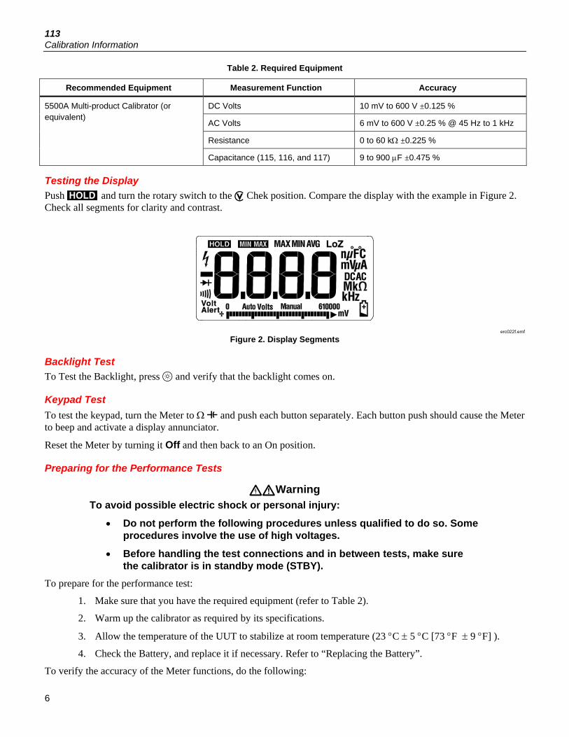
Testing the Display Push and turn the rotary switch to the Chek position. Compare the display with the example in Figure 2. Check all segments for clarity and contrast.
erc022f.emf
Figure 2. Display Segments
Backlight Test To Test the Backlight, press and verify that the backlight comes on.
Keypad Test To test the keypad, turn the Meter to Ω and push each button separately. Each button push should cause the Meter to beep and activate a display annunciator.
Reset the Meter by turning it Off and then back to an On position.
Preparing for the Performance Tests
Warning To avoid possible electric shock or personal injury:
• Do not perform the following procedures unless qualified to do so. Some procedures involve the use of high voltages.
• Before handling the test connections and in between tests, make sure the calibrator is in standby mode (STBY).
To prepare for the performance test:
1. Make sure that you have the required equipment (refer to Table 2).
2. Warm up the calibrator as required by its specifications.
3. Allow the temperature of the UUT to stabilize at room temperature (23 °C ± 5 °C [73 °F ± 9 °F] ).
4. Check the Battery, and replace it if necessary. Refer to “Replacing the Battery”.
To verify the accuracy of the Meter functions, do the following:

Electrical Multimeter Calibration Adjustment
7
1. Connect the Calibrator to the + and COM input terminals on the Meter.
2. Turn the rotary switch to the function listed in each step of Table 3.
3. Apply the input level for each step listed in Table 3.
4. Compare the reading on the Meter display with the Display Reading in Table 3.
5. If the display reading falls outside of the range shown in Table 3, the Meter requires calibration adjustment or repair.
Table 3. Meter Performance Tests
Step Function Range Applied Display Reading
1 Ohms
600.0 0.0 Ω 0.0 to 0.2 (2-Wire comp)
2 600.0 500 Ω 495.3 to 504.7
3 6.000 k 5 kΩ 4.954 to 5.046
4 60.00 k 50 kΩ 49.54 to 50.46
5 Chek Continuity
NA 20 Ω Beeper On
6 NA 250 Ω Beeper Off
7 Chek Diode Test NA 1.9 V 1.859 to 1.941
8
Chek Volts [1]
6.000 V 0.1 V 0.095 to 0.105
9 6.000 V 5 V 4.897 to 5.103
10 6.000 V -5 V -5.103 to -4.897
11 6.000 V 5 V, 45 Hz 4.897 to 5.103
12 6.000 V 5 V, 1 kHz 4.797 to 5.203
13 60.00 V 50 V 48.97 to 51.03
14 60.00 V -50 V -51.03 to -48.97
15 60.00 V 50 V, 500 Hz 48.97 to 51.03
16 60.00 V 50 V, 1 kHz 47.97 to 52.03
17 600.0 V [2] 600 V 587.7 to 612.3
18 600.0 V [2] -600 V -612.3 to -587.7
19 600.0 V [2] 600 V, 45 Hz 587.7 to 612.3
20 600.0 V [2] 600 V, 1 kHz 575.7 to 624.3
21 Capacitance
1000 nF Open 0 to 2
22 9999 µF 900 µF 881 to 919
[1] Manually select the range by pressing .
[2] To keep from tripping the calibrator to standby, ramp up the voltage in 50 V increments with a five-second delay between increments.
Calibration Adjustment The Meter features closed-case calibration adjustment using known reference sources. The Meter measures the applied reference source, calculates correction factors, and stores the correction factors in nonvolatile memory.

113 Calibration Information
8
The following sections present the features and Meter pushbutton functions available during the Calibration Adjustment Procedure. Should the Meter fail any of the performance tests, perform the Calibration Adjustment Procedure.
Use the following steps to view the Meter’s calibration counter.
1. While pressing , turn the rotary switch from OFF to Ω function. The Meter should display “”.
2. Press once to view the calibration counter. For example, “”
3. Turn the rotary switch to OFF.
Calibration Adjustment Password To start the Calibration Adjustment Procedure, the correct 4-digit password must be entered. The default password is “”. The password can be changed or reset to the default as described in following paragraphs.
Changing the Password Use the following steps to change the Meter’s password:
1. While pressing , turn the rotary switch from OFF to Ω function. The Meter should display “”.
2. Press once to see the calibration counter.
3. Press again to start the password entry. The Meter displays “”.
4. The Meter buttons indicated below represent the numbers 1 through 5 when entering or changing the password:
= 1 = 2 = 3 = 4 = 5
5. Press 4 buttons to enter the current password. If changing the password for the first time, enter (1), (2), (3), and (4).
6. Press to change the password. The Meter displays “” if the entered password is correct. If the password is not correct, the Meter emits a double beep, displays “”, and the password must be entered again. Repeat step 5.
7. Press the 4 buttons of the new password.
8. Press to store the new password.
Restoring the Default Password If the calibration password is forgotten, the default password (1234) can be manually restored using the following steps:
Warning To avoid electric shock or personal injury, remove the test leads and any input signal before removing the Meter’s back case.
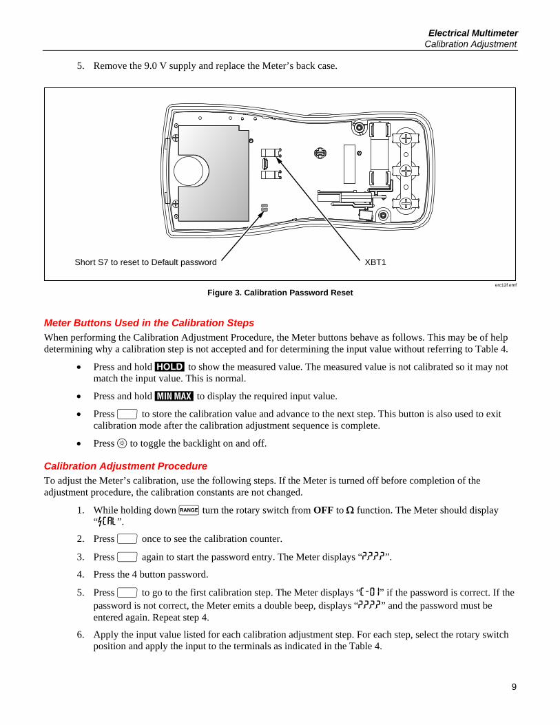
1. Remove the Meter’s back case. Leave the pca in the top case.
2. Apply 9.0 V across the battery contacts (XBT1) + and (XBT2) – on the back of the PCA. See Figure 3.
3. Turn the rotary switch from OFF to any on position.
4. Short across the S7 CAL keypad on the back of the PCA. See Figure 3. The Meter should beep. The default password is now restored.
Electrical Multimeter Calibration Adjustment
9
5. Remove the 9.0 V supply and replace the Meter’s back case.
Short S7 to reset to Default password XBT1
erc12f.emf
Figure 3. Calibration Password Reset
Meter Buttons Used in the Calibration Steps When performing the Calibration Adjustment Procedure, the Meter buttons behave as follows. This may be of help determining why a calibration step is not accepted and for determining the input value without referring to Table 4.
• Press and hold to show the measured value. The measured value is not calibrated so it may not match the input value. This is normal.
• Press and hold to display the required input value.
• Press to store the calibration value and advance to the next step. This button is also used to exit calibration mode after the calibration adjustment sequence is complete.
• Press to toggle the backlight on and off.
Calibration Adjustment Procedure To adjust the Meter’s calibration, use the following steps. If the Meter is turned off before completion of the adjustment procedure, the calibration constants are not changed.
1. While holding down turn the rotary switch from OFF to Ω function. The Meter should display “”.
2. Press once to see the calibration counter.
3. Press again to start the password entry. The Meter displays “”.
4. Press the 4 button password.
5. Press to go to the first calibration step. The Meter displays “” if the password is correct. If the password is not correct, the Meter emits a double beep, displays “” and the password must be entered again. Repeat step 4.
6. Apply the input value listed for each calibration adjustment step. For each step, select the rotary switch position and apply the input to the terminals as indicated in the Table 4.

113 Calibration Information
10
Note Some adjustment steps require additional wait time after the calibrator settles, as noted in Table 4.
7. After each input value is applied, press to accept the value and proceed to the next step ( and so forth).
Note After pressing , wait until the step number advances before changing the calibrator source or turning the Meter’s rotary knob. Some adjustment steps can take up to several seconds to execute before moving to the next step.
If the knob is not in the correct position for a given step, the meter will flash the unit annunciators until the knob is put in a valid position. The keys that show the reading and required input values are not allowed until the knob is correct.
Likewise, if the rotary switch is not in the correct position or the measured value is not within the anticipated range of the input value, the Meter will emit a double beep and will not continue to the next step when is pressed.
8. After the final step, the display shows “” to indicate that the calibration adjustment is complete. Press to return to meter mode.
Note Set the calibrator to Standby prior to changing the function switch position and after completing adjustment of each function.
If the calibration adjustment procedure is not properly completed, the Meter will not operate correctly.
Table 4. Calibration Adjustment Steps
Rotary Switch
Position Calibration Steps Input
Terminals Calibrator
Source Value
CHEK
mV ac/dc + and COM 0 V, 0 Hz
+ and COM 300 mV, 0 Hz
+ and COM 100 mV, 0 Hz
+ and COM -300 mV, 0 Hz
+ and COM 60 mV, 0 Hz
+ and COM 600 mV, 0 Hz
+ and COM 600 mV, 60 Hz
Ohms
+ and COM 600 , 2-wire comp
+ and COM 6 k
+ and COM 60 k
+ and COM 600 k
CHEK
V ac
+ and COM 6 V, 60 Hz
+ and COM 60 V, 60 Hz
+ and COM 600 V, 60 Hz [1]
[1] To keep from tripping the calibrator to standby, ramp up the voltage in 50 V increments with a 5 second delay between increments.

Electrical Multimeter Replacement Parts
11
Replacement Parts Table 5 lists the Meter’s replaceable parts identified in Figure 4.
erc14.eps
Figure 4. Exploded View of Meter

113 Calibration Information
12
Table 5. Replaceable Parts List
Item Description Part Number Qty.
1 LCD,FLUKE-11X,3.2V,TN,4-DIGIT,1/4-DUTY,1/3-BIAS,LEPTON 2509955 1
2 CONNECTOR,ELASTOMERIC,.010 IN CTR,.218 IN HIGH,.090 IN THK,2.284 IN LONG,BULK 2534229
1
3 FLUKE-117-2006-08, BRACKET MASK, 113 3088082 1
4 FLUKE-117-8005,DIFFUSER, BACKLIGHT 2535203 1
5 FLUKE-117-2001-04,CASE TOP, 113 3092058 1
6 FLUKE-117-2008,KNOB 2525624 1
7 FLUKE-117-7602,RSOB HOUSING ASSEMBLY 2787083 1
8 FLUKE-117-8001,KEYPAD 2526276 1
9 FLUKE-117-2009,SPRING DETENT 2525636 1
10 FLUKE-117-8009,SHIELD, TOP 2571277 1
11 FLUKE-117-8010,IC SHIELD 2571292 1
12 O-RING,NITRILE,SHORE A 70,15.6MM OD,12.0MM ID ,1.8MM W 2535215 1
13 FLUKE-117-2002,CASE BOTTOM 2525566 1
14 FLUKE-117-2003,BATTERY DOOR 2525575 1
15 SCREW,2-28,.250,PAN,PHILLIPS,STEEL,ZINC-CHROMATE,PLASTITE 48 THREAD FORMING 2516493
4
16 SCREW,M3,4MM,PAN,PHILLIPS,STEEL,ZINC-CHROMATE 2032811 2
17 SCREW,5-14,.750,PAN,PHILLIPS,STEEL,BLACK CHROMATE,THD FORMING 832246 2
18 SCREW,M3X0.5,6MM,PAN,PHILLIPS,STEEL,ZINC-BLACK CHROMATE 2032792 1
19 BATTERY,PRIMARY,MNO2-ZN,9V,505MAH,6LR61,ALKALINE, 17X26X48MM,BULK 614487
1
20 FLUKE 12-8004,SHOCK ABSORBER 878983 1
21 FLUKE-117-2005-02, TILT STAND, 113 3093970 1
22 FLUKE-117-2010,HOLSTER 2525649 1
Not shown INSTRUCTION SHEET,INSTRUCTION SHEET SET, 12 LANG, FLUKE-113 3083192 1

Electrical Multimeter Warranty
13
Warranty This Fluke product will be free from defects in material and workmanship for three years from the date of purchase. This warranty does not cover fuses, disposable batteries, or damage from accident, neglect, misuse, alteration, contamination, or abnormal conditions of operation or handling. Resellers are not authorized to extend any other warranty on Fluke’s behalf. To obtain service during the warranty period, contact your nearest Fluke authorized service center to obtain return authorization information, then send the product to that Service Center with a description of the problem. THIS WARRANTY IS YOUR ONLY REMEDY. NO OTHER WARRANTIES, SUCH AS FITNESS FOR A PARTICULAR PURPOSE, ARE EXPRESSED OR IMPLIED. FLUKE IS NOT LIABLE FOR ANY SPECIAL, INDIRECT, INCIDENTAL OR CONSEQUENTIAL DAMAGES OR LOSSES, ARISING FROM ANY CAUSE OR THEORY. Since some states or countries do not allow the exclusion or limitation of an implied warranty or of incidental or consequential damages, this limitation of liability may not apply to you.
Fluke Corporation P.O. Box 9090 Everett, WA 98206-9090 U.S.A.
Fluke Europe B.V. P.O. Box 1186 5602 BD Eindhoven The Netherlands
11/99

113 Calibration Information
14
Related Documents