Welcome message from author
This document is posted to help you gain knowledge. Please leave a comment to let me know what you think about it! Share it to your friends and learn new things together.
Transcript


Principles of
ELECTRICAL MACHINES[FOR DEGREE, A.M.I.E., DIPLOMA AND OTHER
ENGINEERING EXAMINATIONS]
Created with Print2PDF. To remove this line, buy a license at: http://www.software602.com/

Principles ofELECTRICAL MACHINES
[FOR DEGREE, A.M.I.E., DIPLOMA AND OTHERENGINEERING EXAMINATIONS]
V.K. MEHTA
ROHIT MEHTA
S. CHAND & COMPANY LTD.(AN ISO 9001 : 2000 COMPANY)RAM NAGAR, NEW DELHI-110 055
Created with Print2PDF. To remove this line, buy a license at: http://www.software602.com/

!" #$%&' ( #)*+%&, -.'"/%0 1!) 2334 5 6333 #789:0;<!"#$ %&&'(" ! "#$%& '() *(+('& *,- .,/01 2 %%3 34456789: ! ;#$";3<32<%2<;& =<==%3">>$& ==%%#%3<<<?@AB ! =%2%%2;#$"">>$C67D AE! =>?:0@AB7C9">78D ,2FAGH! =>?:0@EF=0G">78
)*#+(,"- !
I %:E @H77J& 09JGEAK9& *9AJ +LMAJAE NGO6PAD99E6& (:6JAF '7AO&%?8H@:I:@2#<3 3%>Q 56Q ;"4>%=$4& ;"4>;#$=& A6F9OARAOS:T6A8OKJ7LDQT7F
I *7Q $& (6LMA U6AFR9J:& %:E UJ7::& VLFAJA VJLDA '7AO&J:0A:G7BH24$3 33%Q 56 ! ;;;$<3><& ;;#4>33<& RA8KAH7J9S:T6A8OKJ7LDQT7F
I ;#<2( )Q5Q *AKAJ& W789 %& J?79:G 2 >$; 3%%Q 56 ! >;">";#Q R67DAHS:T6A8OKJ7LDQT7FI %4;& (88A CAHAG& #?H00:K2$33 33;Q 56 ! ;<>$33;$& T6988AGS:T6A8OKJ7LDQT7FI CQUQXQ ;>%=2;3& @GJ:E @H77J& C9TE7J2 ;;2U Y*9AJ (J7FA 07E9HZ& #?:0@KA:B?2%$33;;&
562;";4>>#& ;";4>>$& T6A8OGKAJ6S:T6A8OKJ7LDQT7FI %:E @H77J& [6AJEGA \7]9J& [AOAFRAOG& #CLL:>M2"4# 33=& 562;##;4<3? ;##;4<%&
TLEEAT^S:T6A8OKJ7LDQT7FI %:E @H77J& 4;2(& 'AMDLJ '7AO& 'H?B:@C02;>< 33%Q 56 ! ;">3<<=& ;">3<$%&
O96JAOL8S:T6A8OKJ7LDQT7FI 5A8 [A_AJ& NCO:?:LK2"<% 33%Q 56 ! ;"#<<%%& KL]A6AEGS:T6A8OKJ7LDQT7FI CLHEA8 [A_AJ& $;@HB:I:@2433 %=4Q 56 ! ;>$4%%#4& ;>">><%4& 6PO9JARAOS:T6A8OKJ7LDQT7FI )AG 0GJA8 +AE9& P:G:0@?:B 2 %>>33< Q 56Q ;>3%$#3& 4333$#3& MAHA8O6AJS:T6A8OKJ7LDQT7FI (2%> `A8EA CE7J9 C67DDG8K U7FDH9B& a8Gb9J:GEP )AJK& [ADL *AKAJ& P:K9CB 2 #3; 3%4&
Phone : 2719126, MAGDLJS:T6A8OKJ7LDQT7FI $%#2"& )Q+Q '7AO& ,J8A^LHAF& Q7>?K2$<; 3#4Q 56 ! ;#"<;3"& T7T6G8S:T6A8OKJ7LDQT7FI ;<4c`& [GDG8 [G6AJG +A8KLHG CEJ99E& Q7GM:L:2"33 3%;Q 56 ! ;;#$">4=& ;;#"#=%>&
^7H^AEAS:T6A8OKJ7LDQT7FI )A6AR99J )AJ^9E& ;4 +]P889 '7AO& (FG8ARAO& -C>M07O2;;$ 3%<Q 56 ! ;$;$<3%& ;;<><%4&
HLT^87]S:T6A8OKJ7LDQT7FI [HAT^G9 07L:9& %3#c4& -AHT6A8O 0GJAT6A8O )AJK & XDDQ +Q5QXQ& *C8I:K2>33 33%Q
56 ! ;;$=3<<%& ;;$%3<<4& FLFRAGS:T6A8OKJ7LDQT7FI VAJ8AH [AK& )7O9H )GHH U67]^R aFJ9J '7AO& &:A9CB2>>3 3#; 56 ! ;";#=3%& ;"""$$$
8AKDLJS:T6A8OKJ7LDQT7FI %3>& UGEGT98EJ9 (:67^& +7bG8O )GEJA '7AO& +:L0:2<33 33>Q 56 ! ;#33><=& ;#3;%33&
DAE8AS:T6A8OKJ7LDQT7FI ;=%c%& +A89:6 +APAEJG U7FDH9B& %:E @H77J& C7F]AJD9E6& *9AJ `AG8 )A8OGJ& +C0H2>%%3%%Q
56 ! $>3%";=<& DL89S:T6A8OKJ7LDQT7FI @HAE *7Q %3>& CJG .JALDAOG CFJGEG (DAJEF98E& ,A:E 7d `AGDAH CG8K6 CEAOGLF& *99H 'AEA8 CEJ99E&
aDD9J [A_AJ& S:0>?K2<#>33%" 56! ;;3<"$%& JA8T6GS:T6A8OKJ7LDQT7FI VAGHA:6 '9:GO98TP& 5H7E *7Q >[& [7EEH9 07L:9 '7AO& C6A8^AJ *AKAJ& S:K9CB" 56Q 3==<%;33<#>
JAGDLJS:T6A8OKJ7LDQT7F
© 2002, V.K. Mehta, Rohit Mehta
All rights reserved. No part of this publication may be reproduced, stored in a retrievalsystem or transmitted, in any form or by any means, electronic, mechanical, photocopying,recording or otherwise, without the prior permission of the Publishers.
.'*-/ 0$'/'1+ 23324"5*'+/- 23367 2338 9:;'("<7 233= 9:;'("<4"5*'+/ 233>?"(1+$ 0$'/'1+ 233@
1C[* ! <%2;%=2;%=%23U7O9 ! %3( ;>#5'1*\,. 1* 1*.1(
)A 4#B"+$*# 4#C'+$*# D*'+/"*- 9DC/E< F/$E7 =G8H7 4#I J#K#*7 J"; L"M,'NHH3 366#+$ 5OPM'-,"$ PA ?E Q,#+$ R Q1I5#+A F/$E7 =G8H7 4#I J#K#*7 J"; L"M,'NHH3 366E
Created with Print2PDF. To remove this line, buy a license at: http://www.software602.com/
PREFACE TO THE SECOND EDITION
The general response to the first edition of the book was very encouraging. Authors feel thattheir work has been amply rewarded and wish to express their deep sense of gratitude, in common tothe large number of readers who have used it, and in particular to those of them who have sent helpfulsuggestions from time to time for the improvement of the book.
In the present revised edition, we have made sincere efforts to make the book up-to-date. Thisedition has three notable features. First, three new chapters viz. Electromechanical Energy Conver-sion, Circle Diagrams and Special-purpose Electric Machines have been added. Secondly, a largenumber of solved examples have been added to enhance the utility of the book. Thirdly, the book hasbeen made design oriented keeping in view the growing demand of the industry. It is hoped that thesefeatures will make the book more useful.
Authors wish to thank their colleagues and friends who have contributed many valuable sug-gestions regarding the scope and content-sequence of the book. Authors are also indebted to M/s S.Chand & Company Ltd., New Delhi for bringing out this revised edition in a short time and pricing thebook moderately inspite of heavy cost of paper and printing.
Errors might have crept in despite utmost care to avoid them. Authors shall be grateful if theseare pointed out along with other suggestions for the improvement of the book.
V.K. MEHTA
ROHIT MEHTA
(v)
Created with Print2PDF. To remove this line, buy a license at: http://www.software602.com/
CONTENTS1. ELECTROMECHANICAL ENERGY CONVERSION 1—25
Electromechanical Energy Conversion – Electromechanical Energy Conversion Devices –Features of Electromechanical Energy Conversion – Energy Balance Equation – Energy inMagnetic System – Energy and Coenergy – Field Energy and Mechanical Force – Linear System– Rotating Electrical Machines – Motors and Generators – Basic Construction of ElectricalMachines – Commonly Used Electrical Machines – Multiply - Excited Magnetic System.
2. D.C. GENERATORS 26—80Generator Principle – Simple Loop Generator – Action of Commutator – Construction of D.C.Generator – General Features of D.C. Armature Windings – Commutator Pitch (YC) – Pole-Pitch – Coil Span or Coil Pitch (YS) – Full-Pitched Coil – Types of D.C. Armature Windings –Further Armature Winding Terminology – General Rules For D.C. Armature Windings –Relations between Pitches for Simplex Lap Winding – Simplex Wave Winding – Design ofSimplex Wave Winding – Dummy Coils – Applications of Lap and Wave Windings – MultiplexWindings – Function of Commutator and Brushes - E.M.F. Equation of a D.C. Generator -Armature Resistance (Ra) - Types of D.C. Generators – Separately Excited D.C. Generators –Self-Excited D.C. Generators – Brush Contact Drop – Electromechanical Energy Conversionin a Generator – Losses in a D.C. Machine – Constant and Variable Losses – Power Stages –Condition for Maximum Efficiency.
3. ARMATURE REACTION AND COMMUTATION 81—104
Armature Reaction – Geometrical and Magnetic Neutral Axes – Explanation of ArmatureReaction – Demagnetising and Cross - Magnetising Conductors – Calculation of DemagnetisingAmpere-Turns Per Pole (ATd /Pole) – Cross-Magnetising Ampere-Turns Per Pole (ATc/Pole) –Compensating Windings – AT/Pole for Compensating Windings – Commutation – Calculationof Reactance Voltage – Methods of Improving Commutation – Resistance Commutation –E.M.F. Commutation – Interpoles or Compoles – Equalising Connections – Important Factsabout D.C. Generators.
4. D.C. GENERATOR CHARACTERISTICS 105—144
D.C. Generator Characteristics – Open Circuit Characteristic of a D.C. Generator – Characteristicsof a Separately Excited D.C. Generator – Voltage Build-up in a Self-Excited Generator – CriticalField Resistance for a Shunt Generator – Critical Resistance for a Series Generator –Characteristics of Series Generator – Characteristics of a Shunt Generator – Critical ExternalResistance for Shunt Generator – How to Draw O.C.C. at Different Speeds ? – Critical Speed(NC) – Conditions for Voltage Build-up of a shunt Generator – Compound GeneratorCharacteristics – Voltage Regulation – Need for Parallel Operation of D.C. Generators –Conditions for Parallel Operation of Shunt Generators – Connecting Shunt Generators in Parallel– Load Sharing by Shunt Generators in Parallel – Parallel Operation of Compound Generators– Parallel Operation of Series Generators – D.C. Generator Specifications – Frame Size VersusSpeed of Electrical Machines.
(vii)
Created with Print2PDF. To remove this line, buy a license at: http://www.software602.com/

5. D.C. MOTORS 145—189
D.C. Motor Principle – Working of D.C. Motor – Back or Counter E.M.F. – Significance ofBack E.M.F. – Voltage Equation of D.C. Motor – Power Equation – Condition for MaximumPower – Types of D.C. Motors – Armature Torque of D.C. Motor – Shaft Torque (Tsh) – BrakeHorse Power (b.h.p.) – Speed of a D.C. Motor – Speed Relations – Speed Regulation – Torqueand Speed of a D.C. Motor – Armature Reaction in D.C. Motors – Commutation in D.C. Motors– Losses in a D.C. Motor – Efficiency of a D.C. Motor – Power Stages – D.C. MotorCharacteristics – Characteristics of Shunt Motors – Characteristics of Series Motors – CompoundMotors – Characteristics of Cumulative Compound Motors – Comparison of Three Types ofMotors – Applications of D.C. Motors – Troubles in D.C. Motors.
6. SPEED CONTROL OF D.C. MOTORS 190—236
Speed Control of D.C. Motors – Speed Control of D.C. Shunt Motors – Speed Control of D.C.Series Motors – Series-Parallel Control – Electric Braking – Speed Control of CompoundMotors – Necessity of D.C. Motor Starter – Types of D.C. Motor Starters – Three-Point Starter– Four-Point Starter – Grading of Starting Resistance-Shunt Motors – Starter Step Calculationsfor D.C. Shunt Motor.
7. TESTING OF D.C. MACHINES 237—261Efficiency of a D.C. Machine – Efficiency by Direct Loading – Swinburne’s Method forDetermining Efficiency – Regenerative or Hopkinson’s Test – Alternate Connections forHopkinson’s Test – Advantages of Hopkinson’s Test – Retardation or Running Down Test –Moment of Inertia (I) of the Armature – Electric Loading in Retardation Test.
8. TRANSFORMER 262—370Transformer – Theory of an Ideal Transformer – E.M.F. Equation of a Transformer – VoltageTransformation Ratio (K) – Practical Transformer – Practical Transformer on No Load – IdealTransformer on Load – Practical Transformer on Load – Impedance Ratio – Shifting Impedancein a Transformer – Importance of Shifting Impedances – Exact Equivalent Circuit of a LoadedTransformer – Simplified Equivalent Circuit of a Loaded Transformer – Approximate EquivalentCircuit of Loaded Transformer – Approximate Voltage Drop in a Transformer – VoltageRegulation – Transformer Tests – Open-Circuit or No-Load Test – Short-Circuit or ImpedanceTest – Advantages of Transformers Tests – Separation of Components of Core Losses – WhyTransformer Rating in kVA ? – Sumpner or Back-to-Back Test – Losses in a Transformer –Efficiency of a Transformer – Efficiency from Transformer Tests – Condition for MaximumEfficiency – Output kVA Corresponding to Maximum Efficiency – All-Day (or Energy)Efficiency – Construction of a Transformer – Types of Transformer – Cooling of Transformers– Transformer Rating – Autotransformer – Theory of Autotransformer – Saving of Copper inAutotransformer – Advantages and Disadvantages of Autotransformers – Applications ofAutotransformers – Conversion of Two-Winding Transformer into Autotransformer – ParallelOperation of Single-Phase Transformers – Single-Phase Equal Voltage Ratio Transformers inParallel – Single-Phase Unequal Voltage Ratio Transformers in Parallel – Three-PhaseTransformer – Three-Phase Transformer Connections – Three-Phase Transformation with TwoSingle-Phase Transformers – Open-Delta or V-V Connection – Power Factor of Transformersin V-V Circuit – Applications of Open-Delta or V-V Connection – Scott Connection or T-TConnection – Three Phase Transformer Connections and Phase Shift – Parallel Operation of3-phase Transformers – Applications of Transformers – Instrument Transformers – CurrentTransformer (C.T.) – Potential Transformer (P.T.) – Advantages of Instrument Transformers.
(viii)
Created with Print2PDF. To remove this line, buy a license at: http://www.software602.com/

9. THREE-PHASE INDUCTION MOTORS 371—449Three-phase Induction Motor – Construction – Rotating Magnetic Field Due to 3-Phase Currents– Alternate Analysis for Rotating Magnetic Field – Principle of Operation – Slip – RotorCurrent Frequency – Effect of Slip on the Rotor Circuit – Rotor Current – Rotor Torque –Starting Torque (TS) – Condition for Maximum Starting Torque – Effect of Change of SupplyVoltage – Starting Torque of 3-phase Induction Motors – Motor Under Load – Torque UnderRunning Conditions – Maximum Torque Under Running conditions – Torque-slip Characteristics– Full-load, Starting and Maximum Torques – Torque-speed Curve of 3-phase Induction Motor– Characteristics of Squirrel - Cage Motors – Speed Regulation of Induction Motors – PowerFactor of Induction Motor – Measurement of Slip – Power Stages in an Induction Motor –Induction Motor Torque – Rotor Output – Induction Motor Torque Equation – PerformanceCurves of Squirrel-Cage Motor – Plugging of an Induction Motor – Braking Induction Motorwith Direct Current – Induction Generator – Applications of Induction Generators – CompleteTorque/Slip Curve of Induction Machine – Induction Motor and Transformer Compared –Equivalent Circuit of 3- Induction Motor at Slip s – Equivalent Circuit of the Rotor –Transformer Equivalent Circuit of Induction Motor – Power Relations – Approximate EquivalentCircuit of Induction Motor – Starting of 3-Phase Induction Motors – Methods of Starting3-Phase Induction Motors – Methods of Starting Squirrel-Cage Motors – Starting of Slip-RingMotors – Slip-Ring Motors Versus Squirrel Cage Motors – Induction Motor Rating – AbnormalOperation of 3-Phase Induction Motors – Double Squirrel-Cage Motors – Equivalent Circuitof Double Squirrel-Cage Motor.
10. CIRCLE DIAGRAMS 450—495Circle Diagram for R-L Series Circuit – Importance of Circle Diagrams – Circle Diagram of3- Induction Motor – Data Required for Circle Diagram – Tests to Obtain Data for CircleDiagram – Construction of Circle Diagram – Complete Circle Diagram of Induction Motor –Maximum Quantities from Circle Diagram – Speed Control of Induction Motors – Speed Controlby Changing Number of Stator Poles – Speed Control by Changing Line Frequency – SpeedControl by Changing Applied Voltage – Speed Control by Changing Rotor Circuit Resistance– Speed Control by Injecting Voltage in Rotor Circuit – Speed Control by Cascade Connection– Rotor Rheostat Starter for Slip-Ring Motors – Classes of Squirrel-Cage Induction Motors –Crawling of Induction Motors – Cogging – Linear Induction Motor (LIM) – Properties ofLinear Induction Motor.
11. SINGLE-PHASE MOTORS 496—529Types of Single-Phase Motors – Single-Phase Induction Motors – Double Field RevolvingTheory – Making Single-phase Induction Motor Self-Starting – Rotating Magnetic Field from2-Phase Supply – Split-Phase Induction Motor – Capacitor-Start Motor – Capacitor-StartCapacitor-Run Motor – Shaded-Pole Motor – Equivalent Circuit of Single-Phase InductionMotor – A.C. Series Motor or Universal Motor – Single-Phase Repulsion Motor – Repulsion-Start Induction-Run Motor – Repulsion-Induction Motor – Single-Phase Synchronous Motors– Reluctance Motor – Hysteresis Motor.
12. ALTERNATORS 530—615Alternator – Construction of Alternator – Alternator Operation – Frequency – A.C. ArmatureWindings – Armature Winding of Alternator – Winding Factors – E.M.F. Equation of anAlternator – Armature Reaction in Alternator – Alternator on Load – Synchronous Reactance(Xs) – Phasor Diagram of a Loaded Alternator – Voltage Regulation – Determination of VoltageRegulation – Synchronous Impedance Method – Ampere-Turn Method – Procedure for ATMethod – Zero Power Factor Method or Potier Method – Procedure for Potier Method – Power
(ix)
Created with Print2PDF. To remove this line, buy a license at: http://www.software602.com/

Output in Cylindrical Rotor – Power/Power Angle Characteristics – Effect of Salient Poles –Two-Reactance Concept for Salient-Poles Machines – Power Developed in Salient-PoleSynchronous Generator – V Curves for Alternator – Parallel Operation of Alternators –Advantages of Parallel Operation of Alternators – Conditions for Paralleling Alternator withInfinite Busbars – Methods of Synchronisation – Synchronising Action – Synchronising Power– Alternators Connected to Infinite Busbars – Effect of Load on Synchronising Power – Sharingof Load Current by Two Alternators in Parallel – Alternators on Infinite Busbars – Effect ofChange of Excitation and Mechanical Input – Hunting.
13. SYNCHRONOUS MOTORS 616—649Construction – Some Facts about Synchronous Motor – Operating Principle – MakingSynchronous Motor Self-Starting – Equivalent Circuit – Motor on Load – Pull-out Torque –Motor Phasor Diagram – Effect of Changing Field Excitation at Constant Load – PhasorDiagrams with Different Excitation – V Curves for Synchronous Motor - Power Relations –Motor Torque – Mechanical Power Developed by Motor – Power Factor of Synchronous Motors– Synchronous Condenser – Stopping Synchronous Motors – Applications of SynchronousMotors – Comparison of Synchronous and Induction Motors.
14. SPECIAL-PURPOSE ELECTRIC MACHINES 650—665Stepper Motor – Permanent-Magnet (PM) Stepper Motor – Variable-Reluctance (VR) StepperMotor – Hybrid Stepper Motor – Servomechanism – D.C. Servomotors – A.C. Servomotor –Switched Reluctance Motor (SRM) – Permanent-Magnet DC Motor – Brushless D.C. Motors.
INDEX 666–669
(x)
Created with Print2PDF. To remove this line, buy a license at: http://www.software602.com/

1
1Electromechanical Energy Conversion
INTRODUCTIONWe daily use many devices that convert one form of energy into another form. For example, a heaterconverts electrical energy into heat energy while an electric bulb converts electrical energy into lightenergy. However, electromechanical conversion devices (i.e., devices that convert electrical energyinto mechanical energy or vice – versa) find wide practical applications. For example, an electricmotor converts electrical energy into mechanical energy. On the other hand, an electric generatorconverts mechanical energy into electrical energy. A major reason for the widespread use of electro-mechanical energy conversion devices is that they are relatively efficient and permit an easy control.In this chapter, we shall discuss the basic principles of electromechanical energy conversion.
1.1 ELECTROMECHANICAL ENERGY CONVERSIONThe conversion of electrical energy into mechanical energy or vice versa is known as electrome-chanical energy conversion.
Electromechanical energy conversion involves the interchange of energy between an electricalsystem and a mechanical system through the medium of a coupling electric field or magnetic field.Therefore, an electromechanical conversion system has three essential parts viz., an electrical system, amechanical system and a coupling field (electric or magnetic). Fig. 1.1 shows the block diagram of anelectromechanical energy conversion system. Note that from left to right, the system represents con-version from electrical to mechanical . However, from right to left, it will represent conversion frommechanical to electrical.
ElectricalSystem
Mech.output
CouplingField
MechanicalSystem
Elect.input
Fig. 1.1 Electromechanical Energy Conversion System(i) Electric field as coupling medium. Electromechanical energy conversion can take place
when electric field is used as the medium. Consider two oppositely charged plates of a capacitorwhich are separated by a dielectric medium. A force of attraction exists between the two plates thattends to move them together. If we allow one plate to move in the direction of the force, we areconverting electrical energy into mechanical energy. On the other hand, if we apply an external forceon one plate and try to increase the separation between them, we are then converting mechanicalenergy into electrical energy. Electrostatic microphones and electrostatic voltmeters use electrostaticfields for energy conversion.
(ii) Magnetic field as coupling medium. Electromechanical energy conversion can also takeplace more effectively when magnetic field is used as the medium. Consider the case of a current-carrying conductor placed in a magnetic field. The conductor experiences a force that tends to moveit. If the conductor is free to move in the direction of the magnetic force, the magnetic field helps theconversion of electrical energy into mechanical energy. This is essentially the principle of operationof all electric motors. On the other hand, if an externally applied force moves the conductor in adirection opposite to the magnetic force, mechanical energy is converted into electrical energy. Thegenerator action is based on this principle. Note that in both cases, the magnetic field acts as a me-dium for energy conversion.
Created with Print2PDF. To remove this line, buy a license at: http://www.software602.com/
2 Principles of Electrical Machines
It is important to note that the quantity of energy that can be converted by a device using electricfield as a medium is relatively small. It is because the amount of force developed by an electricsystem is usually very small even when the applied voltage is high and the physical dimensions of thesystem are quite large. However, when magnetic field is used as a medium, a system with the samephysical dimensions develops a much larger force than a system using an electric field as a medium.For this reason, the use of electric field as a medium for energy conversion has limited applications.
1.2 ELECTROMECHANICAL ENERGY CONVERSION DEVICESElectromechanical energy conversion takes place through electric field or magnetic field as the me-dium. Although the various conversion devices operate on common set of physical principles, thestructures of the devices depend on their function. Electromechanical energy conversion devices canbe divided into the following three categories :
(i) Transducers. These conversion devices are used for measurement and control. They generallyoperate under linear input-output conditions and with relatively small signals. Examplesinclude microphones, pick ups and loudspeakers.
(ii) Force-producing devices. These conversion devices are meant for producing force or torquewith limited mechanical motion. Examples include relays, solenoid actuators and electromagnets.
(iii) Continuous energy conversion devices. These devices continuously convert electricalenergy into mechanical energy or vice versa. They are used for bulk energy conversion andutilisation. Motors and generators are the examples of such conversion devices.
It may be noted that magnetic field is most suited as a medium for electromechanical energyconversion. Therefore, in this book, we shall deal with magnetic field as the medium of energy conversion.
1.3 FEATURES OF ELECTROMECHANICAL ENERGY CONVERSIONElectromechanical energy conversion takes place through the medium of magnetic field. The follow-ing salient features are worth noting in this energy conversion :
(i) As with any energy conversion system, the principle of conservation of energy holds goodin case of electromechanical energy conversion. That is energy can neither be created nordestroyed; it can only be changed from one form to another.
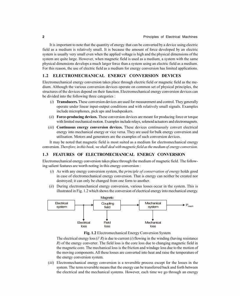
(ii) During electromechanical energy conversion, various losses occur in the system. This isillustrated in Fig. 1.2 which shows the conversion of electrical energy into mechanical energy.
Electricalsystem
Electricalloss
Fieldloss
Mechanicalloss
Pmech Coupling
fieldMechanical
system
Magnetic
Fig. 1.2 Electromechanical Energy Conversion SystemThe electrical energy loss (i2 R) is due to current (i) flowing in the winding (having resistanceR) of the energy converter. The field loss is the core loss due to changing magnetic field inthe magnetic core. The mechanical loss is the friction and windage loss due to the motion ofthe moving components. All these losses are converted into heat and raise the temperature ofthe energy conversion system.
(iii) Electromechanical energy conversion is a reversible process except for the losses in thesystem. The term reversible means that the energy can be transferred back and forth betweenthe electrical and the mechanical systems. However, each time we go through an energy
Created with Print2PDF. To remove this line, buy a license at: http://www.software602.com/
Electromechanical Energy Conversion 3
conversion process, some of the energy is used up to meet the losses in the conversionprocess. These losses are converted into heat and are lost from the system forever.
(iv) Electromechanical conversion devices are built with air gaps in the magnetic circuit to separatethe fixed and moving parts. Most of the m.m.f. of the windings is required to overcome theair-gap reluctance so that most of the energy is stored in the air gap and is returned to theelectric source when the field is reduced.
(v) The electromechanical energy conversion system can be analysed by using principle of con-servation of energy, laws of electric and magnetic field, electric circuits and Newtonian mechanics.
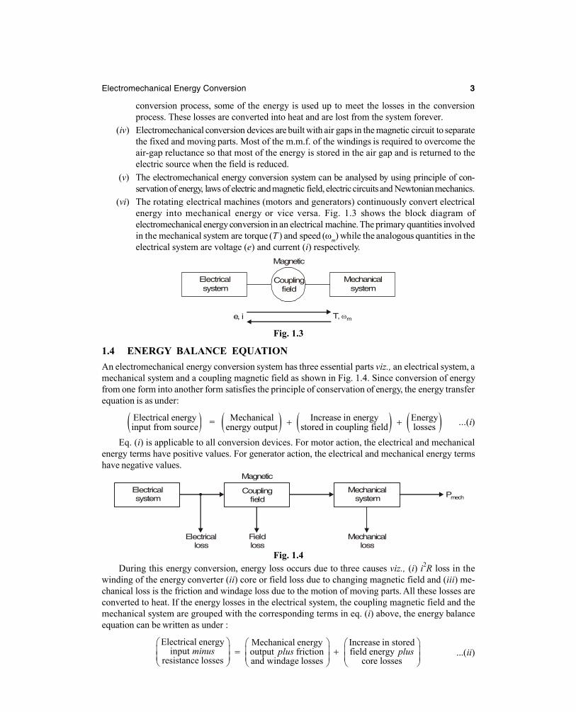
(vi) The rotating electrical machines (motors and generators) continuously convert electricalenergy into mechanical energy or vice versa. Fig. 1.3 shows the block diagram ofelectromechanical energy conversion in an electrical machine. The primary quantities involvedin the mechanical system are torque (T ) and speed (m) while the analogous quantities in theelectrical system are voltage (e) and current (i) respectively.
Magnetic
Couplingfield
Mechanicalsystem
Electrical system
e, i T, m
Fig. 1.3
1.4 ENERGY BALANCE EQUATIONAn electromechanical energy conversion system has three essential parts viz., an electrical system, amechanical system and a coupling magnetic field as shown in Fig. 1.4. Since conversion of energyfrom one form into another form satisfies the principle of conservation of energy, the energy transferequation is as under:
Electrical energyinput from source = Mechanical Increase in energy Energy
energy output stored in coupling field losses ...(i)
Eq. (i) is applicable to all conversion devices. For motor action, the electrical and mechanicalenergy terms have positive values. For generator action, the electrical and mechanical energy termshave negative values.
Electricalsystem
Electricalloss
Fieldloss
Mechanicalloss
PmechCoupling
fieldMechanical
system
Magnetic
Fig. 1.4During this energy conversion, energy loss occurs due to three causes viz., (i) i2R loss in the
winding of the energy converter (ii) core or field loss due to changing magnetic field and (iii) me-chanical loss is the friction and windage loss due to the motion of moving parts. All these losses areconverted to heat. If the energy losses in the electrical system, the coupling magnetic field and themechanical system are grouped with the corresponding terms in eq. (i) above, the energy balanceequation can be written as under :
Electrical energyinput
resistance losses
minus =Mechanical energy Increase in storedoutput friction field energyand windage losses core losses
plus plus ...(ii)
Created with Print2PDF. To remove this line, buy a license at: http://www.software602.com/
4 Principles of Electrical Machines
Now consider a differential time dt during which an increment of electrical energy dWelect (exclud-ing i2R loss) flows to the system. During this time dt, let dWfld be the energy supplied to the field(either stored or lost, or part stored and part lost) and dWmech the energy converted to mechanical form (inuseful form or as loss, or part useful and part as loss). In differential form, eq. (ii) can be expressed as
dWelect = dWmech + dWfld ...(iii)If no mechanical work is done [i.e. dWmech = 0], then eq. (iii) becomes :
dWelect = dWfldIn this case, electrical energy input is stored in the magnetic field (neglecting core losses).
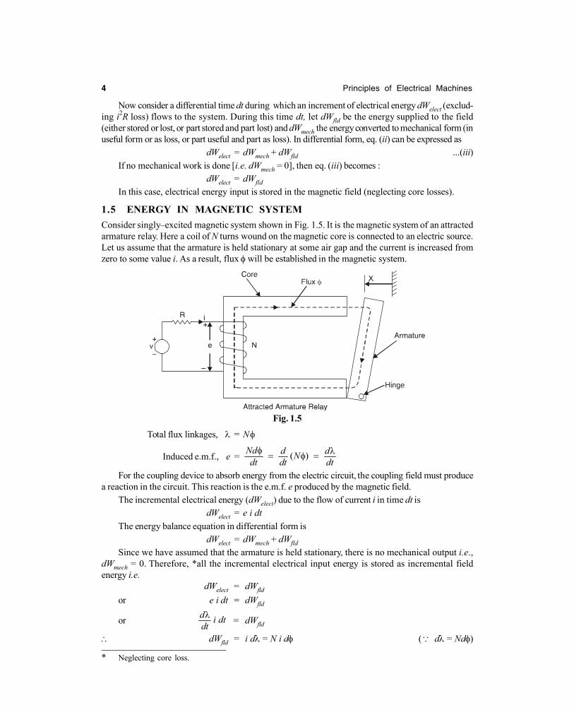
1.5 ENERGY IN MAGNETIC SYSTEMConsider singly–excited magnetic system shown in Fig. 1.5. It is the magnetic system of an attractedarmature relay. Here a coil of N turns wound on the magnetic core is connected to an electric source.Let us assume that the armature is held stationary at some air gap and the current is increased fromzero to some value i. As a result, flux will be established in the magnetic system.
Fig. 1.5
Total flux linkages, = N
Induced e.m.f., e = ( )Nd d dNdt dt dt
For the coupling device to absorb energy from the electric circuit, the coupling field must producea reaction in the circuit. This reaction is the e.m.f. e produced by the magnetic field.
The incremental electrical energy (dWelect) due to the flow of current i in time dt isdWelect = e i dt
The energy balance equation in differential form isdWelect = dWmech + dWfld
Since we have assumed that the armature is held stationary, there is no mechanical output i.e.,dWmech = 0. Therefore, *all the incremental electrical input energy is stored as incremental fieldenergy i.e.
dWelect = dWfld
or e i dt = dWfld
or d i dtdt = dWfld
dWfld = i d = N i d ( d = Nd)
* Neglecting core loss.
Created with Print2PDF. To remove this line, buy a license at: http://www.software602.com/
Electromechanical Energy Conversion 5
The relationship between coil flux linkages and current i for aparticuler air-gap length is shown in Fig. 1.6. The incremental fieldenergy dWfld is shown as crosshatched area in this figure. Whenthe flux linkage is increased from zero to (or flux from zero to ),the energy stored in the field is
Wfld =0 0
id N id
The integral repesents the area between the axis and the -icharacteristic and is equal to the entire shaded area shown in Fig. 1.6.
We can also derive another useful expression for the energy stored in the magnetic field. If l andA are the length and area of cross – section of the magnetic circuit respectively and B is the magneticflux density, then,
Ni = Hl and d = A dBHere H is the magnetic field intensity.
Wfld = N0 0 0
B B
id HlAdB Al HdB
or Wfld =0
B
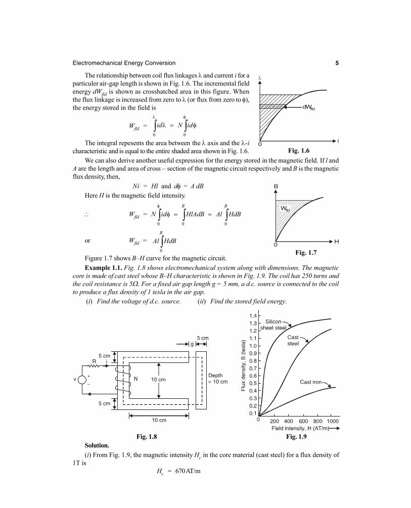
Al HdBFigure 1.7 shows B–H curve for the magnetic circuit.Example 1.1. Fig. 1.8 shows electromechanical system along with dimensions. The magnetic
core is made of cast steel whose B–H characteristic is shown in Fig. 1.9. The coil has 250 turns andthe coil resistance is 5. For a fixed air gap length g = 5 mm, a d.c. source is connected to the coilto produce a flux density of 1 tesla in the air gap.
(i) Find the voltage of d.c. source. (ii) Find the stored field energy.
Fig. 1.8 Fig. 1.9Solution.(i) From Fig. 1.9, the magnetic intensity Hc in the core material (cast steel) for a flux density of
1T isHc = 670 AT/m
Fig. 1.6
Fig. 1.7
dWfld
i0
H0
B
Wfld
Created with Print2PDF. To remove this line, buy a license at: http://www.software602.com/
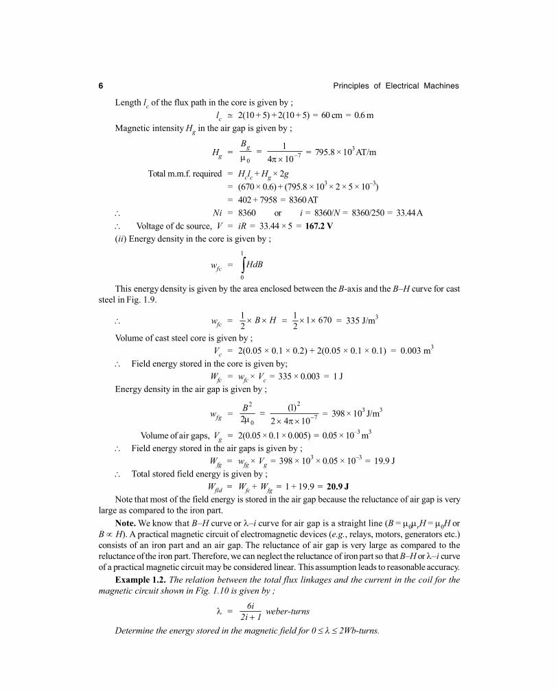
6 Principles of Electrical Machines
Length lc of the flux path in the core is given by ;lc 2(10 + 5) + 2(10 + 5) = 60 cm = 0.6 m
Magnetic intensity Hg in the air gap is given by ;
Hg = 70
14 10
gB
= 795.8 × 10³ AT/m
Total m.m.f. required = Hclc + Hg × 2g= (670 × 0.6) + (795.8 × 103 × 2 × 5 × 10–3)= 402 + 7958 = 8360 AT
Ni = 8360 or i = 8360/N = 8360/250 = 33.44 A Voltage of dc source, V = iR = 33.44 × 5 = 167.2 V(ii) Energy density in the core is given by ;
wfc =1
0
HdBThis energy density is given by the area enclosed between the B-axis and the B–H curve for cast
steel in Fig. 1.9.
wfc = 1 1 1 6702 2
B H = 335 J/m3
Volume of cast steel core is given by ;Vc = 2(0.05 × 0.1 × 0.2) + 2(0.05 × 0.1 × 0.1) = 0.003 m3
Field energy stored in the core is given by;Wfc = wfc × Vc = 335 × 0.003 = 1 J
Energy density in the air gap is given by ;
wfg =22
70
(1)2 2 4 10B
= 398 × 103 J/m3
Volume of air gaps, Vg = 2(0.05 × 0.1 × 0.005) = 0.05 × 10⁻³ m3
Field energy stored in the air gaps is given by ;Wfg = wfg × Vg = 398 × 103 × 0.05 × 10–3 = 19.9 J
Total stored field energy is given by ;Wfld = Wfc + Wfg = 1 + 19.9 = 20.9 J
Note that most of the field energy is stored in the air gap because the reluctance of air gap is verylarge as compared to the iron part.
Note. We know that B–H curve or –i curve for air gap is a straight line (B = 0rH = 0H orB H). A practical magnetic circuit of electromagnetic devices (e.g., relays, motors, generators etc.)consists of an iron part and an air gap. The reluctance of air gap is very large as compared to thereluctance of the iron part. Therefore, we can neglect the reluctance of iron part so that B–H or –i curveof a practical magnetic circuit may be considered linear. This assumption leads to reasonable accuracy.
Example 1.2. The relation between the total flux linkages and the current in the coil for themagnetic circuit shown in Fig. 1.10 is given by ;
= 6i2i 1
weber-turns
Determine the energy stored in the magnetic field for 0 2Wb-turns.
Created with Print2PDF. To remove this line, buy a license at: http://www.software602.com/

Principle Of Electrical Machines
Publisher : SChand Publications ISBN : 9788121921916 Author : Rohit Mehta
Type the URL : http://www.kopykitab.com/product/10737
Get this eBook
20%OFF
Related Documents