Transformer presented by, A.Johny Renoald AP/EEE Electrical department.

Welcome message from author
This document is posted to help you gain knowledge. Please leave a comment to let me know what you think about it! Share it to your friends and learn new things together.
Transcript

Transformer
presented by,
A.Johny Renoald AP/EEE
Electrical department.

Transformer
An A.C. device used to change high voltage low current A.C. into low voltage high current A.C. and vice-versa without changing the frequency
In brief,
1. Transfers electric power from one circuit to another
2. It does so without a change of frequency
3. It accomplishes this by electromagnetic induction
4. Where the two electric circuits are in mutual inductive influence of each other.

Principle of operation
It is based on principle of MUTUAL INDUCTION. According to which an e.m.f. is induced in a coil when current in the neighbouring coil changes.

Constructional detail : Shell type
• Windings are wrapped around the center leg of a laminated core.

Core type
• Windings are wrapped around two sides of a laminated square core.

Sectional view of transformers
Note: High voltage conductors are smaller cross section conductors than the low voltage coils

Construction of transformer from stampings

Core type
Fig1: Coil and laminations of core type transformer
Fig2: Various types of cores

Shell type
• The HV and LV windings are split into no. of sections
• Where HV winding lies between two LV windings
• In sandwich coils leakage can be controlled
Fig: Sandwich windings
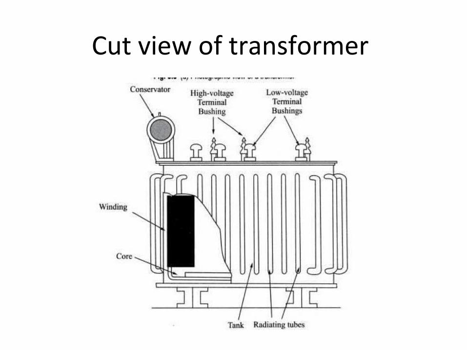
Cut view of transformer

Transformer with conservator and breather

Working of a transformer
1. When current in the primary coil changes being alternating in nature, a changing magnetic field is produced
2. This changing magnetic field gets associated with the secondary through the soft iron core
3. Hence magnetic flux linked with the secondary coil changes.
4. Which induces e.m.f. in the secondary.


Ideal Transformers• Zero leakage flux:
-Fluxes produced by the primary and secondary currents are confined within the core
• The windings have no resistance:
- Induced voltages equal applied voltages
• The core has infinite permeability
- Reluctance of the core is zero
- Negligible current is required to establish magnetic flux
• Loss-less magnetic core
- No hysteresis or eddy currents
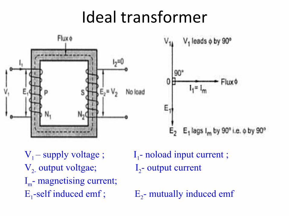
Ideal transformer
V1 – supply voltage ; I1- noload input current ; V2- output voltgae; I2- output currentIm- magnetising current; E1-self induced emf ; E2- mutually induced emf
Φ C
vp
ip
P
Np
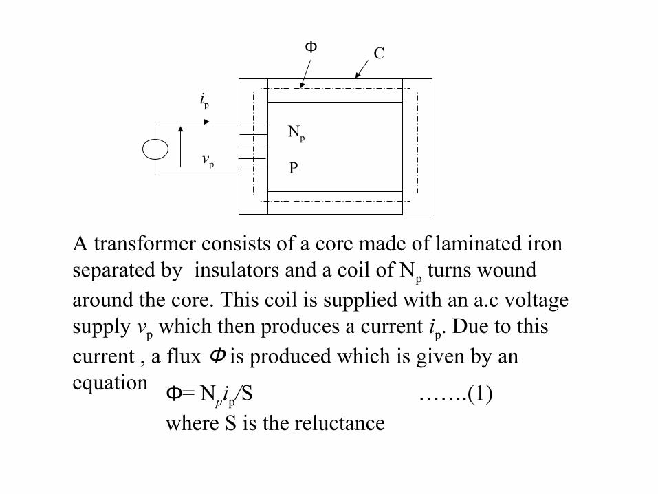
Φ= Npip/S …….(1)where S is the reluctance
A transformer consists of a core made of laminated iron separated by insulators and a coil of Np turns wound around the core. This coil is supplied with an a.c voltage supply vp which then produces a current ip. Due to this current , a flux Φ is produced which is given by an equation

dt
dN pp
ϕ=v
)(dt
dNp
2p
p iv ×ℜ
=
Since current varied with time , Φ also varied with time. A back electromagnetic force (e.m.f) will be produced which is given by the equation.
Substitute Φ = Npip/S into the above equation , then
……(2)
……(3)
( )dt
2sindNpp
ftv m πΦ=
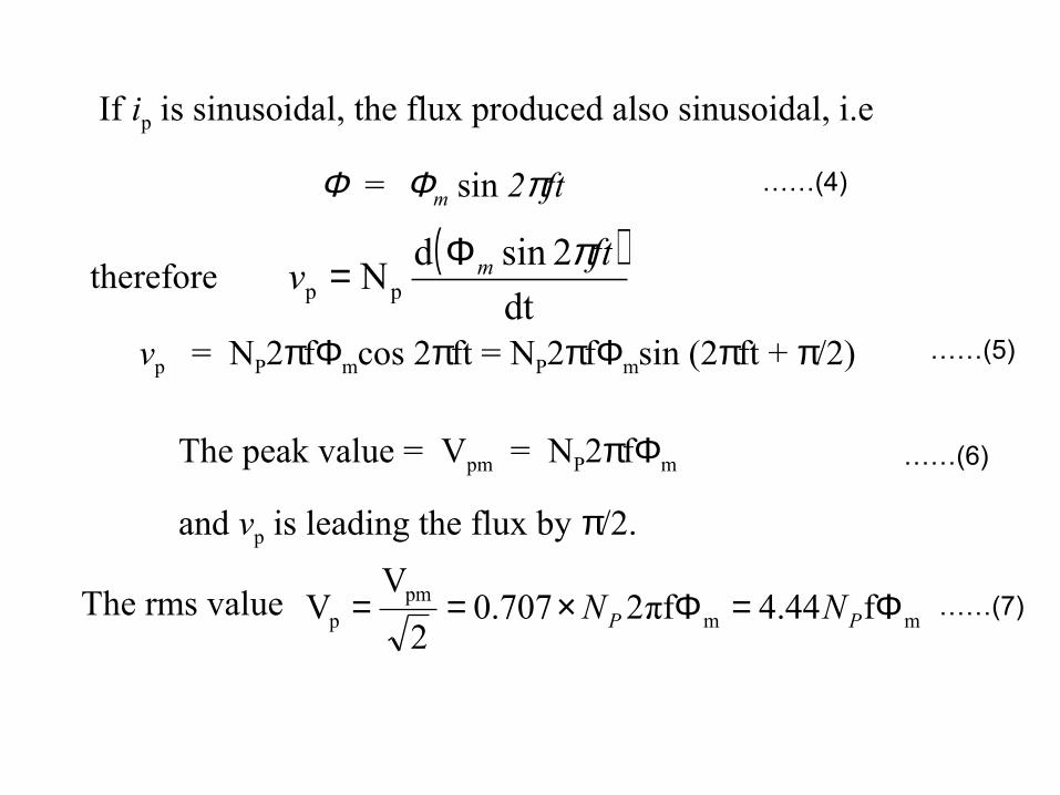
Φ = Φm sin 2πft
If ip is sinusoidal, the flux produced also sinusoidal, i.e
therefore
vp = NP2πfΦmcos 2πft = NP2πfΦmsin (2πft + π/2)
The peak value = Vpm = NP2πfΦm
and vp is leading the flux by π/2.
mmpm
p f44.4πf2707.02
VV Φ=Φ×== PP NNThe rms value
……(4)
……(5)
……(6)
……(7)

Phasor diagram: Transformer on No-load

Transformer on load assuming no voltage drop in the winding
Fig shows the Phasor diagram of a transformer on load by assuming1.No voltage drop in the winding2.Equal no. of primary and secondary turns

Transformer on load
Fig. a: Ideal transformer on loadFig. b: Main flux and leakage flux in a transformer

Phasor diagram of transformer with UPF load

Phasor diagram of transformer with lagging p.f load

Phasor diagram of transformer with leading p.f load

Equivalent circuit of a transformer
No load equivalent circuit:

Equivalent circuit parameters referred to primary and secondary sides respectively
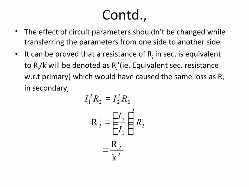
Contd.,• The effect of circuit parameters shouldn’t be changed while
transferring the parameters from one side to another side
• It can be proved that a resistance of R2 in sec. is equivalent to R2/k2
will be denoted as R2’(ie. Equivalent sec. resistance w.r.t primary) which would have caused the same loss as R2 in secondary,
22
2
2
1
2'2
222
'2
21
k
R
R
=
=
=
RI
I
RIRI
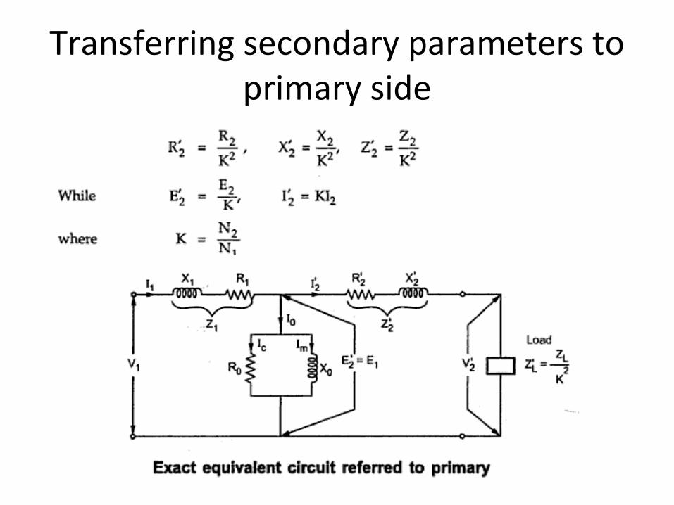
Transferring secondary parameters to primary side

Equivalent circuit referred to secondary side
•Transferring primary side parameters to secondary side
Similarly exciting circuit parameters are also transferred to secondary as Ro’ and Xo’

equivalent circuit w.r.t primary
where

Approximate equivalent circuit
• Since the noload current is 1% of the full load current, the nolad circuit can be neglected

Transformer Tests
Electrical Machines
•The performance of a transformer can be calculated on the basis of equivalent circuit•The four main parameters of equivalent circuit are:
- R01 as referred to primary (or secondary R02)- the equivalent leakage reactance X01 as referred to primary
(or secondary X02)- Magnetising susceptance B0 ( or reactance X0)- core loss conductance G0 (or resistance R0)
•The above constants can be easily determined by two tests- Oper circuit test (O.C test / No load test)- Short circuit test (S.C test/Impedance test)
•These tests are economical and convenient- these tests furnish the result without actually loading the transformer

In Open Circuit Test the transformer’s secondary winding is open-circuited, and its primary winding is connected to a full-rated line voltage.
• Usually conducted on H.V side
• To find
(i) No load loss or core loss
(ii) No load current Io which is helpful in finding Go(or Ro ) and Bo (or Xo )
20
200
20
oc00
20oc
0
0o000
22000m
00wc
000
000
B esusceptanc Exciting &
V
WG econductanc Exciting ;GV W
Y ;YVI
sinI I
cosI I
cos
cosloss Core
GY
V
I
-IIIor
Ior
IV
W
IVW
w
oc
oc
−=
=∴=
=∴=
==
=
=
==
φ
φ
φ
φ
µ
Open-circuit Test
00
00
00
00
V
IB
V
IG
I
VX
I
VR
w
w
µ
µ
=
=
=
=

Short-circuit TestIn Short Circuit Test the secondary terminals are short circuited, and the primary terminals are connected to a fairly low-voltage source
The input voltage is adjusted until the current in the short circuited windings is equal to its rated value. The input voltage, current and power is measured.
• Usually conducted on L.V side• To find
(i) Full load copper loss – to pre determine the efficiency
(ii) Z01 or Z02; X01 or X02; R01 or R02 - to predetermine the voltage regulation

Contd…
201
20101
01
2sc
01
012
sc
X
WR
W losscu load Full
RZ
I
VZ
I
RI
sc
sc
sc
sc
−=∴
=
=
==

Transformer Voltage Regulation and Efficiency
Electrical Machines
The output voltage of a transformer varies with the load even if the input voltage remains constant. This is because a real transformer has series impedance within it. Full load Voltage Regulation is a quantity that compares the output voltage at no load with the output voltage at full load, defined by this equation:
%100down Regulation
%100up Regulation
,
,,
,
,,
×−
=
×−
=
nlS
flSnlS
flS
flSnlS
V
VV
V
VV ( )
( )%100
/down Regulation
%100/
up Regulation
V
Vk noloadAt
,
,
,
,
p
s
xV
VkV
xV
VkV
nlS
flSP
flS
flSP
−=
−=
=
Ideal transformer, VR = 0%.

voltageload-no
voltageload-fullvoltageload-noregulationVoltage
−=
=
1
212 N
NVV
p
s
p
s
N
N
V
V =recall
Secondary voltage on no-load
V2 is a secondary terminal voltage on full load
−
=
1
21
21
21
regulationVoltage
NN
V
VNN
VSubstitute we have

Transformer Phasor Diagram
01/27/15 38Electrical Machines Aamir Hasan Khan
To determine the voltage regulation of a transformer, it is necessary understand the voltage drops within it.

Transformer Phasor Diagram
01/27/15 39Electrical Machines Aamir Hasan Khan
Ignoring the excitation of the branch (since the current flow through the branch is considered to be small), more consideration is given to the series impedances (Req +jXeq).
Voltage Regulation depends on magnitude of the series impedance and the phase angle of the current flowing through the transformer.
Phasor diagrams will determine the effects of these factors on the voltage regulation. A phasor diagram consist of current and voltage vectors.
Assume that the reference phasor is the secondary voltage, VS. Therefore the reference phasor will have 0 degrees in terms of angle.
Based upon the equivalent circuit, apply Kirchoff Voltage Law,
SeqSeqSP IjXIRVk
V++=
Transformer Phasor Diagram
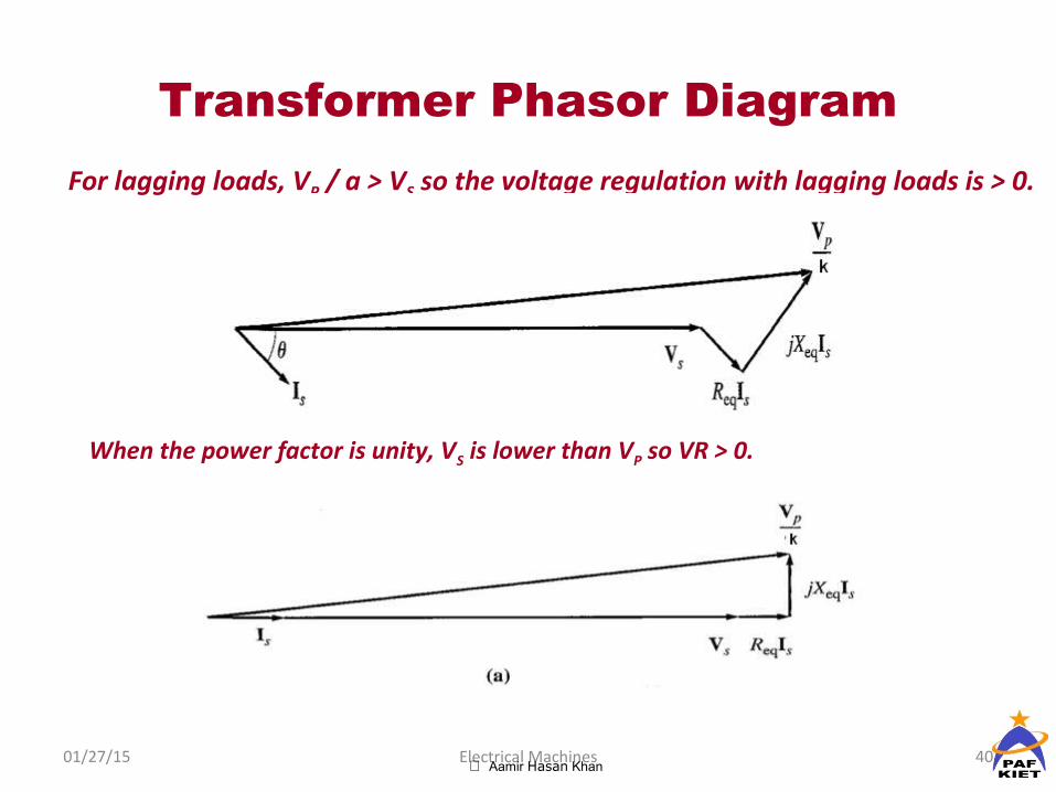
01/27/15 40Electrical Machines Aamir Hasan Khan
For lagging loads, VP / a > VS so the voltage regulation with lagging loads is > 0.
When the power factor is unity, VS is lower than VP so VR > 0.

Transformer Phasor Diagram
01/27/15 41Electrical Machines Aamir Hasan Khan
With a leading power factor, VS is higher than the referred VP so VR < 0

Transformer Phasor Diagram
Electrical Machines
For lagging loads, the vertical components of Req and Xeq will partially cancel each other. Due to that, the angle of VP/a will be very small, hence we can assume that VP/k is horizontal. Therefore the approximation will be as follows:

Formula: voltage regulation
leadingfor '-' and laggingfor ''
V
sincos
V
Vregulation %
luesprimary va of In terms
leadingfor '-' and laggingfor ''
V
sincos
V
Vregulation %
valuessecondary of In terms
1
10111011
1
'21
20
20222022
20
220
+
±=
−=
+
±=
−=
where
XIRIV
where
XIRIV
φφ
φφ

Transformer Efficiency
Electrical Machines
Transformer efficiency is defined as (applies to motors, generators and transformers):
%100×=in
out
P
Pη
%100×+
=lossout
out
PP
Pη
Types of losses incurred in a transformer:Copper I2R lossesHysteresis lossesEddy current losses
Therefore, for a transformer, efficiency may be calculated using the following:
%100cos
cosx
IVPP
IV
SScoreCu
SS
θθη
++=
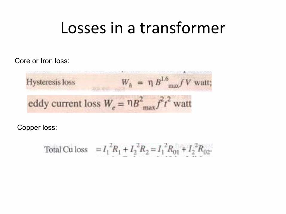
Losses in a transformer
Core or Iron loss:
Copper loss:

Condition for maximum efficiency

Contd.,
The load at which the two losses are equal =

All day efficiency
hours) 24 (kWhin Input
kWhin output
in wattsinput
in wattsput out efficiency commercialordinary
day forall =
=
η
•All day efficiency is always less than the commercial efficiency


Three-Phase Transformers
Three-phase transformer construction.

Construction• A three-phase transformer is constructed by
winding three single-phase transformers on a single core.
• Three-phase transformers are connected in either wye (star) or delta configurations.
• Two or three single-phase transformers can be connected together to deliver three-phase power. This is referred to as a transformer bank.
• This allows greater maintenance and replacement options.
THREE PHASE SYSTEM
BASICS
Line voltage VL= voltage between lines
Phase voltage Vph= voltage between a line and
neutral

THREE PHASE SYSTEM
BALANCED STAR
Line Voltage VL= √3 Vph
Line current IL = Iph

THREE PHASE SYSTEM
BALANCED DELTA
Line Voltage VL= Vph
Line current IL = √3 Iph

THREE PHASE TRANSFORMERS
Almost all major generation & Distribution Systems in the world are three phase ac systems Three phase transformers play an important role in these systems
3 phase transformers can be constructed from
3 single phase transformers
2 single phase transformers
using a common core for three phase windings

3 phase Transformer connections
By connecting three single phase transformers
1. Star- Star connection
2. Delta- Delta connection
3. Star – Delta connection
4. Delta – Star connection
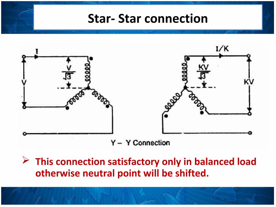
Star- Star connection
This connection satisfactory only in balanced load otherwise neutral point will be shifted.

Star- Star connection
Advantages
1.Requires less turns per winding ie cheaper Phase voltage is 1/√3 times of line voltage
2.Cross section of winding is large ie stronger to bear stress during short circuit Line current is equal to phase current
3. Less dielectric strength in insulating materials phase voltage is less

Star- Star connection
Disadvantages1.If the load on the secondary side unbalanced then the shifting of neutral point is possible
2.The third harmonic present in the alternator voltage may appear on the secondary side. This causes distortion in the secondary phase voltages 3. Magnetizing current of transformer has 3rd harmonic component

Delta - Delta connection
This connection is used for moderate voltages
Delta - Delta connection
Advantages
1.System voltages are more stable in relation to unbalanced load
2. If one t/f is failed it may be used for low power level i.e.-V connection
3. No distortion of flux ie 3rd harmonic current not flowing to the line wire

Delta - Delta connection
Disadvantages
1. Compare to Y-Y require more insulation
2. Absence of star point i.e. fault may severe

Star- Delta connection
Used to step down voltage ie end of transmission line

Star- Delta connection
Advantages1.The primary side is star connected. Hence fewer number of turns are required. This makes the connection economical
2.The neutral available on the primary can be earthed to avoid distortion.
3.Large unbalanced loads can be handled satisfactory.

Star- Delta connection
Disadvantages
1.The secondary voltage is not in phase with the primary. (30 ⁰ phase difference )
2.Hence it is not possible to operate this connection in parallel with star-star or delta-delta connected transformer.

Delta - Star connection
This connection is used to step up voltage ie. Beginning of high tension line

Delta - Star connection
Features
secondary Phase voltage is 1/√3 times of line voltage
neutral in secondary can be grounded for 3 phase 4 wire system
Neutral shifting and 3rd harmonics are there
Phase shift of 30⁰ between secondary and primary currents and voltages

Scott -connection


Parallel operation of two phase transformers

1. The voltage ratio must be the same.
2. The per unit impedance of each machine on its own base must be the same.
3. The polarity must be the same, so that there is no circulating current between the transformers.
4. The phase sequence must be the same and no phase difference must exist between the voltages of the two transformers.

Tap changing transformer

Tap changing transformer• Regulating the voltage of a transformer is a
requirement that often arises in a power application or power system. In an application it may be needed
1. To supply a desired voltage to the load.
2. To counter the voltage drops due to loads.
3. To counter the input supply voltage changes on load.
Related Documents