Technical data Precision class B according to EN50470-3, 1 according to IEC62053-21 Operating voltage 3 × 230 / 400 VAC, 50 Hz Tolerance –20% /+15% Power consumption Active 0.4 W per phase Counting range 000˙000.0…999 ˙999.9 1˙000˙000…9 ˙999 ˙999 Display LCD backlit, digits 6 mm high Display without mains power Capacitor based LCD max. 2 times over 10 days Mounting Mounting On 35 mm rail, according to EN60715TH35 Terminal connections main circuit Conductor cross-section 1.5 –16 mm 2 , screwdriver pozidrive no. 1, slot no.2, torque 1.5–2 Nm Terminal connections control circuit Conductor cross-section max. 2.5 mm 2 , screwdriver pozidrive no. 0, slot no.2, torque 0.8 Nm Insulation characteristics 4 kV / 50 Hz test according to VDE0435 for energy meter part 6 kV 1.2 / 50 µs surge voltage according to IEC255-4 2 kV/50Hz test according to VDE0435 for interface Device protection class II Ambient temperature –25°…+55° C Storage temperature –30°…+85° C Relative humidity 95% at 25°…+40 °C, without condensation EMC/ interference immunity Surge voltage according to IEC61000-4-5: on main circuit, 4 kV on the M-Bus, 1 kV Burst voltage according to IEC61000-4-4: on main circuit 4 kV on the M-Bus 1 kV ESD according to IEC61000-4-2: contact 8 kV, air 15 kV CT measurement 5…1500 A Reference/max. current I ref = 5 A, I max = 6 A Starting/minimum current I st = 10 mA, I min = 0.05 A Converter ratio 5 : 5 50 : 5 100 : 5 150 : 5 200 : 5 250 : 5 300 : 5 400 : 5 500 : 5 600 : 5 750 : 5 1000 : 5 1250 : 5 1500 : 5 Pulses per kWh LED 10 Imp/kWh Electrical energy meter with integrated M-Bus interface enable the reading of all relevant data such as energy, current, voltage and power (active and reactive). Electrical Energy Meter with integrated M-Bus interface EEM400C-D-M Main Features: ■ 3-phase energy meter, 3 × 230/400 VAC 50 Hz ■ Measurement through a current transformer up to 1500 A ■ Display of active power, voltage and current for every phase ■ Display of active power for all phases ■ M-Bus interface to retrieve the data ■ Reactive power per phase or total, available via M-Bus interface ■ Up to 250 meters can be addressed trough primary addresses ■ 7-digit display ■ Can be sealed with sealing cap (optional) ■ Accuracy class B according to EN50470-3, accuracy class 1 according to IEC62053-21 Order number: Standard Version: EEM400C-D-M MID Version: EEM400C-D-M-MID

Welcome message from author
This document is posted to help you gain knowledge. Please leave a comment to let me know what you think about it! Share it to your friends and learn new things together.
Transcript

Technical dataPrecision class B according to EN50470-3,
1 according to IEC62053-21Operating voltage 3 × 230 / 400 VAC, 50 Hz
Tolerance –20% /+15%Power consumption Active 0.4 W per phaseCounting range 000˙000.0…999˙999.9
1˙000˙000…9˙999˙999Display LCD backlit, digits 6 mm highDisplay without mains power
Capacitor based LCDmax. 2 times over 10 days
MountingMounting On 35 mm rail, according to
EN60715TH35Terminal connections main circuit
Conductor cross-section 1.5 –16 mm2, screwdriver pozidrive no. 1, slot no.2, torque 1.5–2 Nm
Terminal connections control circuit
Conductor cross-section max. 2.5 mm2, screwdriver pozidrive no. 0, slot no.2, torque 0.8 Nm
Insulation characteristics
4 kV / 50 Hz test according to VDE0435 for energy meter part6 kV 1.2 / 50 µs surge voltage according to IEC255-42 kV/50Hz test according to VDE0435 for interface Device protection class II
Ambient temperature –25°…+55° CStorage temperature –30°…+85° CRelative humidity 95% at 25°…+40 °C, without
condensation EMC/interference immunity
Surge voltage according to IEC61000-4-5: on main circuit, 4 kVon the M-Bus, 1 kVBurst voltage according to IEC61000-4-4:on main circuit 4 kVon the M-Bus 1 kVESD according to IEC61000-4-2: contact 8 kV, air 15 kV
CT measurement 5…1500 A
Reference/max. current Iref = 5 A, Imax = 6 AStarting/minimum current Ist = 10 mA, Imin = 0.05 AConverter ratio 5 : 5 50 : 5 100 : 5 150 : 5
200 : 5 250 : 5 300 : 5 400 : 5500 : 5 600 : 5 750 : 5 1000 : 5
1250 : 5 1500 : 5Pulses per kWh LED 10 Imp/kWh
Electrical energy meter with integrated M-Bus interface enable the reading of all relevant data such as energy, current, voltage and power (active and reactive).
Electrical Energy Meter with integrated M-Bus interface EEM400C-D-M
Main Features:■3-phase energy meter, 3 × 230/400 VAC 50 Hz ■Measurement through a current transformer up to 1500 A
■Display of active power, voltage and current for every phase
■Display of active power for all phases
■M-Bus interface to retrieve the data■Reactive power per phase or total, available via M-Bus
interface■Up to 250 meters can be addressed trough primary
addresses ■7-digit display ■Can be sealed with sealing cap (optional)■Accuracy class B according to EN50470-3,
accuracy class 1 according to IEC62053-21
Order number: Standard Version: EEM400C-D-MMID Version: EEM400C-D-M-MID

2 |
CT Select
82
27
62
4,5
6
70
65 x 11,7 = (58,5)
768
4,5930,5 9
11
57,7
22,7
35
69,5
3162
70
9
57.7
30.5
22.7
4.5
1135
5 x 11.7 = [58.5] 6
4.5
27
31
4582
69.5
768
6
9
Data sheet – Electrical Energy Meter with integrated M-Bus interface
Dimensioned drawings
Display elements ■ T1 total Indicates total consumption ■ T1 part Indicates partial consumption
This value can be reset ■ CT Indicates the setting for the
current transformer ratio ■ Select When bridge Z1-Z2 is open, the transformer
ratio can be adjusted under menu item: Select ■ P (kW) Indicates the instantaneous output per phase
or for all phases■ U (V) Indicates voltage per phase■ I (A) Indicates current per phase■ kWh Indicates the unit kWh for display of consumption■ L1 / L2 / L3 Whenever the display shows P, U, I or Error,
the corresponding phase will be indicated■ Error When phase is absent or current direction
is wrong. The corresponding phase will also be indicated.
Error display
Example: Connection error at L1 and L3Example: Connection error at L3
CT SelectCT Select

| 3
kWhkWhkWhkWh
CT Select
kWhkWhkWhkWh
CT Select
kWhkWhkWhkWh
CT Select
kWhkWhkWhkWh
CT Select
kWhkWhkWhkWh
CT Select
kWhkWhkWhkWh
CT Select
kWhkWhkWhkWh
CT Select
> 3 s
> 3 skWhkWhkWhkWh
CT Select
kWhkWhkWhkWh
CT Select
kWhkWhkWhkWh
CT Select
EEM400C-D-M 5 … 1500 A
5:5 50:5 100:5 150:5 200:5 250:5 300:5 400:5 500:5 600:5 750:5 1000:5 1250:5 1500:5
kWhkWhkWhkWh
CT Select
kWhkWhkWhkWh
CT Select
kWhkWhkWhkWh
CT Select
kWhkWhkWhkWh
CT Select
kWhkWhkWhkWh
CT Select
kWhkWhkWhkWh
CT Select
kWhkWhkWhkWh
CT Select
kWhkWhkWhkWh
CT Select
kWhkWhkWhkWh
CT Select
kWhkWhkWhkWh
CT Select
kWhkWhkWhkWh> 3 s
kWhkWhkWhkWh
Start
kWhkWhkWhkWh
> 20 s
Data sheet – Electrical Energy Meter with integrated M-Bus interface
Menu to display the value on LCD
Start
T1 total
T1 partial (T1 part)
Ratio Current Transformer (CT)
Instan. Power (P)
Voltage (U)
Current (I)
Start
remove bridge Z1-Z2
restore bridge Z1-Z2

4 |
L1
L2L3N
M-Bus
(PEN)
3 ×
230/
400
VAC
Data sheet – Electrical Energy Meter with integrated M-Bus interface
Wiring diagram
Technical data M-BusBus System M-Bus Bus length According to M-Bus specification Transmission rates 300, 2400, 9600 Bd.
The transmission rate is automatically detected Response time: (system response
Write: up to 60 ms Read: up to 60 ms
Data transfer:
■When reading out the values, all values are transferred in a telegram■ It supports the following telegrams (see page 6 for more detailed information): ■ Initialisation SND_NKE Response: 0xE5 ■ Reading meter REQ_UD2 Response: RSP_UD ■ Changing primary address SND_UD Response: 0xE5 ■ Reset Tpart SND_UD Response: 0xE5■The device does not respond to unknown queries ■The transmission rate is automatically detected ■The device has a voltage monitor. In the case of a power failure, all the registers are saved in the EEPROM.
Changing the M-Bus primary address:■ In order to change the M-Bus primary address, hold down ►■ In the following menu, ▼ increases the address by 10, ► increases the primary address by 1 ■When the desired address is set, wait until the main display appears again
Fuse:T250mA(3x)
The secondary, mains current transformer connec-tion has to be connected to the phase to be measured and therefore the transformer don’t have to be grounded.
| 5Data sheet – Electrical Energy Meter with integrated M-Bus interface
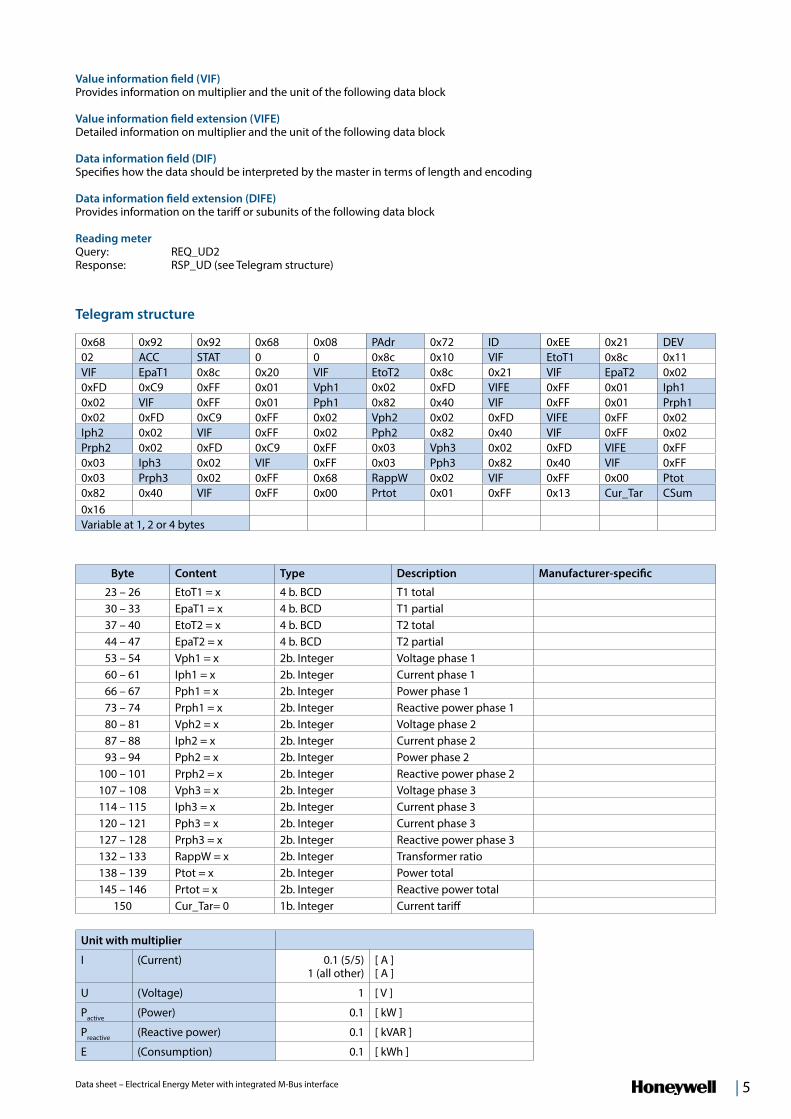
Unit with multiplier
I (Current) 0.1 (5/5) 1 (all other)
[ A ][ A ]
U (Voltage) 1 [ V ]
Pactive (Power) 0.1 [ kW ]
Preactive (Reactive power) 0.1 [ kVAR ]
E (Consumption) 0.1 [ kWh ]
Byte Content Type Description Manufacturer-specific
23 – 26 EtoT1 = x 4 b. BCD T1 total30 – 33 EpaT1 = x 4 b. BCD T1 partial37 – 40 EtoT2 = x 4 b. BCD T2 total44 – 47 EpaT2 = x 4 b. BCD T2 partial53 – 54 Vph1 = x 2b. Integer Voltage phase 160 – 61 Iph1 = x 2b. Integer Current phase 166 – 67 Pph1 = x 2b. Integer Power phase 173 – 74 Prph1 = x 2b. Integer Reactive power phase 180 – 81 Vph2 = x 2b. Integer Voltage phase 287 – 88 Iph2 = x 2b. Integer Current phase 293 – 94 Pph2 = x 2b. Integer Power phase 2
100 – 101 Prph2 = x 2b. Integer Reactive power phase 2107 – 108 Vph3 = x 2b. Integer Voltage phase 3114 – 115 Iph3 = x 2b. Integer Current phase 3120 – 121 Pph3 = x 2b. Integer Current phase 3127 – 128 Prph3 = x 2b. Integer Reactive power phase 3132 – 133 RappW = x 2b. Integer Transformer ratio138 – 139 Ptot = x 2b. Integer Power total 145 – 146 Prtot = x 2b. Integer Reactive power total
150 Cur_Tar= 0 1b. Integer Current tariff
Telegram structure
0x68 0x92 0x92 0x68 0x08 PAdr 0x72 ID 0xEE 0x21 DEV02 ACC STAT 0 0 0x8c 0x10 VIF EtoT1 0x8c 0x11VIF EpaT1 0x8c 0x20 VIF EtoT2 0x8c 0x21 VIF EpaT2 0x020xFD 0xC9 0xFF 0x01 Vph1 0x02 0xFD VIFE 0xFF 0x01 Iph10x02 VIF 0xFF 0x01 Pph1 0x82 0x40 VIF 0xFF 0x01 Prph10x02 0xFD 0xC9 0xFF 0x02 Vph2 0x02 0xFD VIFE 0xFF 0x02Iph2 0x02 VIF 0xFF 0x02 Pph2 0x82 0x40 VIF 0xFF 0x02Prph2 0x02 0xFD 0xC9 0xFF 0x03 Vph3 0x02 0xFD VIFE 0xFF0x03 Iph3 0x02 VIF 0xFF 0x03 Pph3 0x82 0x40 VIF 0xFF0x03 Prph3 0x02 0xFF 0x68 RappW 0x02 VIF 0xFF 0x00 Ptot0x82 0x40 VIF 0xFF 0x00 Prtot 0x01 0xFF 0x13 Cur_Tar CSum0x16Variable at 1, 2 or 4 bytes
Value information field (VIF)Provides information on multiplier and the unit of the following data block
Value information field extension (VIFE)Detailed information on multiplier and the unit of the following data block
Data information field (DIF)Specifies how the data should be interpreted by the master in terms of length and encoding
Data information field extension (DIFE)Provides information on the tariff or subunits of the following data block Reading meter Query: REQ_UD2Response: RSP_UD (see Telegram structure)
6 | Data sheet – Electrical Energy Meter with integrated M-Bus interface
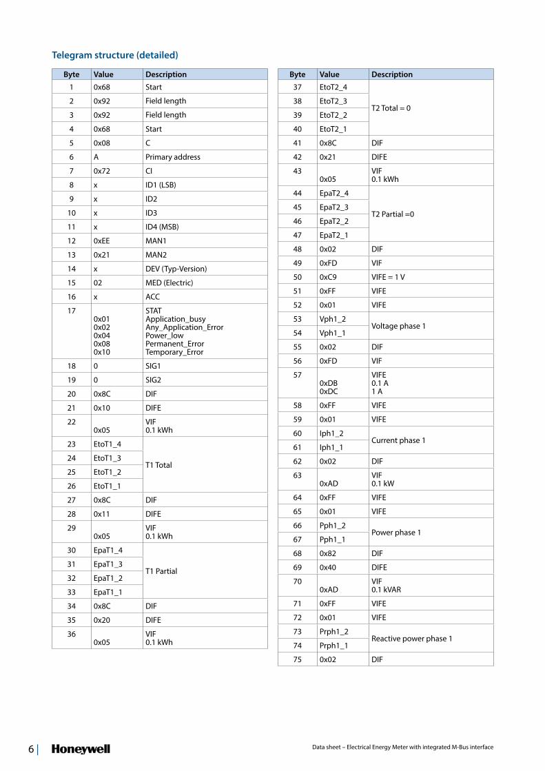
Byte Value Description
1 0x68 Start
2 0x92 Field length
3 0x92 Field length
4 0x68 Start
5 0x08 C
6 A Primary address
7 0x72 CI
8 x ID1 (LSB)
9 x ID2
10 x ID3
11 x ID4 (MSB)
12 0xEE MAN1
13 0x21 MAN2
14 x DEV (Typ-Version)
15 02 MED (Electric)
16 x ACC
170x01 0x02 0x04 0x08 0x10
STATApplication_busy Any_Application_Error Power_low Permanent_Error Temporary_Error
18 0 SIG1
19 0 SIG2
20 0x8C DIF
21 0x10 DIFE
220x05
VIF0.1 kWh
23 EtoT1_4
T1 Total24 EtoT1_3
25 EtoT1_2
26 EtoT1_1
27 0x8C DIF
28 0x11 DIFE
290x05
VIF0.1 kWh
30 EpaT1_4
T1 Partial31 EpaT1_3
32 EpaT1_2
33 EpaT1_1
34 0x8C DIF
35 0x20 DIFE
360x05
VIF0.1 kWh
Byte Value Description
37 EtoT2_4
T2 Total = 038 EtoT2_3
39 EtoT2_2
40 EtoT2_1
41 0x8C DIF
42 0x21 DIFE
430x05
VIF0.1 kWh
44 EpaT2_4
T2 Partial =0 45 EpaT2_3
46 EpaT2_2
47 EpaT2_1
48 0x02 DIF
49 0xFD VIF
50 0xC9 VIFE = 1 V
51 0xFF VIFE
52 0x01 VIFE
53 Vph1_2Voltage phase 1
54 Vph1_1
55 0x02 DIF
56 0xFD VIF
570xDB 0xDC
VIFE0.1 A 1 A
58 0xFF VIFE
59 0x01 VIFE
60 Iph1_2Current phase 1
61 Iph1_1
62 0x02 DIF
630xAD
VIF 0.1 kW
64 0xFF VIFE
65 0x01 VIFE
66 Pph1_2Power phase 1
67 Pph1_1
68 0x82 DIF
69 0x40 DIFE
700xAD
VIF0.1 kVAR
71 0xFF VIFE
72 0x01 VIFE
73 Prph1_2Reactive power phase 1
74 Prph1_1
75 0x02 DIF
Telegram structure (detailed)
| 7Data sheet – Electrical Energy Meter with integrated M-Bus interface
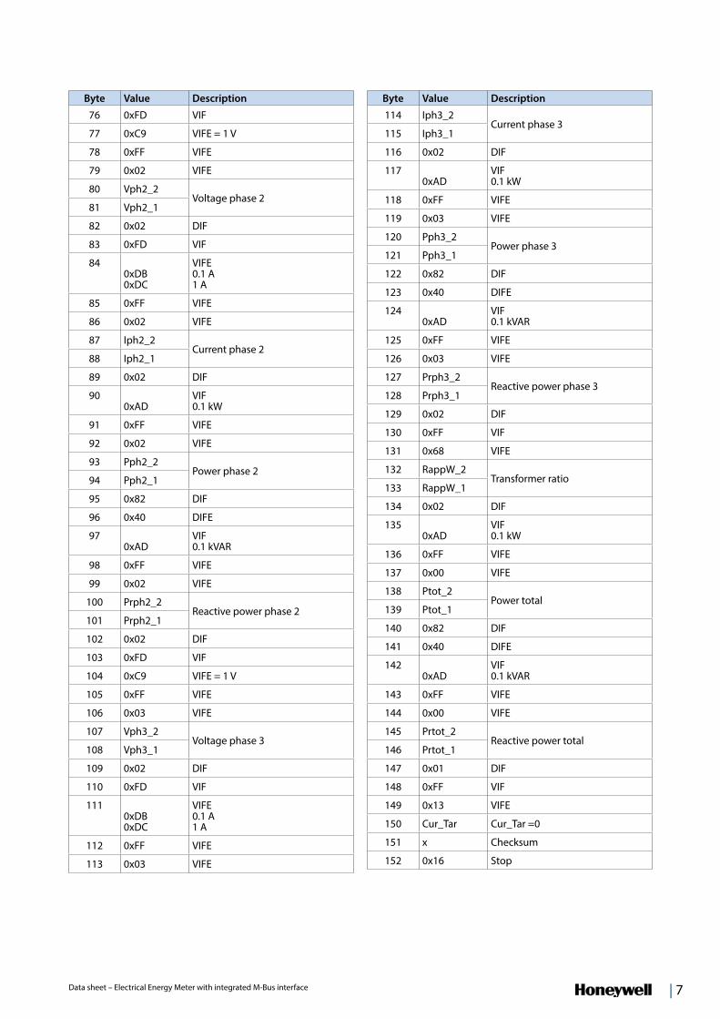
Byte Value Description
76 0xFD VIF
77 0xC9 VIFE = 1 V
78 0xFF VIFE
79 0x02 VIFE
80 Vph2_2Voltage phase 2
81 Vph2_1
82 0x02 DIF
83 0xFD VIF
840xDB0xDC
VIFE0.1 A 1 A
85 0xFF VIFE
86 0x02 VIFE
87 Iph2_2Current phase 2
88 Iph2_1
89 0x02 DIF
900xAD
VIF0.1 kW
91 0xFF VIFE
92 0x02 VIFE
93 Pph2_2Power phase 2
94 Pph2_1
95 0x82 DIF
96 0x40 DIFE
970xAD
VIF0.1 kVAR
98 0xFF VIFE
99 0x02 VIFE
100 Prph2_2Reactive power phase 2
101 Prph2_1
102 0x02 DIF
103 0xFD VIF
104 0xC9 VIFE = 1 V
105 0xFF VIFE
106 0x03 VIFE
107 Vph3_2Voltage phase 3
108 Vph3_1
109 0x02 DIF
110 0xFD VIF
1110xDB 0xDC
VIFE0.1 A 1 A
112 0xFF VIFE
113 0x03 VIFE
Byte Value Description
114 Iph3_2Current phase 3
115 Iph3_1
116 0x02 DIF
1170xAD
VIF0.1 kW
118 0xFF VIFE
119 0x03 VIFE
120 Pph3_2Power phase 3
121 Pph3_1
122 0x82 DIF
123 0x40 DIFE
1240xAD
VIF0.1 kVAR
125 0xFF VIFE
126 0x03 VIFE
127 Prph3_2Reactive power phase 3
128 Prph3_1
129 0x02 DIF
130 0xFF VIF
131 0x68 VIFE
132 RappW_2Transformer ratio
133 RappW_1
134 0x02 DIF
1350xAD
VIF0.1 kW
136 0xFF VIFE
137 0x00 VIFE
138 Ptot_2Power total
139 Ptot_1
140 0x82 DIF
141 0x40 DIFE
1420xAD
VIF0.1 kVAR
143 0xFF VIFE
144 0x00 VIFE
145 Prtot_2Reactive power total
146 Prtot_1
147 0x01 DIF
148 0xFF VIF
149 0x13 VIFE
150 Cur_Tar Cur_Tar =0
151 x Checksum
152 0x16 Stop

Manufactured for and on behalf of the Environmental and Combustion Controls Division of Honeywell Technologies Sàrl, Rolle, Z.A. La Pièce 16, Switzerland by its Authorized Representative:
Saia-Burgess Controls Ltd Bahnhofstrasse 18 CH-3280 Murten / Schweiz
Phone +41 (0)26 672 72 72 Fax +41 (0)26 672 74 99
Subject to change without notice. Printed in Switzerland P+P26/589 EN01 / 05.2013
Initialisation
Query: SND-NKE Response: 0xE5
Telegram structure (brief )
0x10 0x40 Padr CSum 0x16
Telegram structure (detailed)
Byte Value Description
1 0x10 Start
2 0x40 Send or reply, reset
3 Primary address
4 Checksum
5 0x16 Stop
Reset ACC (application reset)
Query: SND_UDResponse: 0xE5
Telegram structure (brief )
0x68 0x03 0x03 0x68 0x53 Padr
0x50 CSum 0x16
Telegram structure (detailed)
Byte Value Description
1 0x68 Start
2 0x03 Field length
3 0x03 Field length
4 0x68 Start
5 0x53 C
6 Primary address
7 0x50 CI
8 Checksum
9 0x16 Stop
Reset Tpart (Application reset with subcode)
Query: SND_UD (Reset Counter: 0x01 = T1) Response: 0xE5
Telegram structure (brief )
0x68 0x04 0x04 0x68 0x53 Padr
0x50 Reset CSum 0x16
Telegram structure (detailed)
Byte Value Description
1 0x68 Start
2 0x04 Field length
3 0x04 Field length
4 0x68 Start
5 0x53 C
6 Primary address
7 0x50 CI
80x01
Reset CounterT1Part
9 Checksum
10 0x16 Stop
Changing primary address
Query: SND_UD (Byte 6 = actual M-Bus address; Byte 10 = new address)Response: 0xE5
Telegram structure (brief )
0x68 0x06 0x06 0x68 0x53 Padr
0x51 0x01 0x7A New A CSum 0x16
Telegram structure (detailed)
Byte Value Description
1 0x68 Start
2 0x06 Field length
3 0x06 Field length
4 0x68 Start
5 0x53 C
6 Primary address
7 0x51 CI
8 0x01 DIF
9 0x7A VIF
10 New address
11 Checksum
12 0x16 Stop
Related Documents


![BUS BUS BUS BUS BUS BUS BUS BUS BUS · Sunday 15 May 2016 Liverpool Street to Colchester, Ipswich, Norwich and branches BUS BUS BUS BUS BUS BUS BUS BUS BUS] 1 1 1 1 1 1 1 1 1 1 1](https://static.cupdf.com/doc/110x72/5fab4ce2477d2d3adf21016a/bus-bus-bus-bus-bus-bus-bus-bus-sunday-15-may-2016-liverpool-street-to-colchester.jpg)