1 Electrical Energy Engineering Department 10/5/2018

Welcome message from author
This document is posted to help you gain knowledge. Please leave a comment to let me know what you think about it! Share it to your friends and learn new things together.
Transcript

1
Electrical
Energy
Engineering
Department
10/5/2018

Introduction: The transmission of electric power is done by 3-
phase, 3-wire overhead lines, a.c. transmission line
has resistance, inductance and capacitance
uniformly distributed along its length. The
performance of a transmission line depends on
parameters mentioned above . The efficiency and
voltage regulation of the line will be good or poor
depending to their parameters. Therefore, the
knowledge of these parameters is required and
necessary in order to make the electrical design of a
transmission line which was given in power course.
Also there are some parameters here must
considered such as thermal effect and corona. 2 Dr audih

Dr audih 3
In order to make a design of OHL of TL firstly must collect
some parameters such as :
1-Temprature: maximum, minimum and average ambient
temperature which influences the conductor current rating
and sag .
The maximum operation temperature of ACSR conductor
should not exceed 75oC (to prevent annealing of aluminum).
2- Wind velocity: effected structure of towers and conductors.
3- Solar radiation :conductors and fittings such as insulation
material (ultraviolet and high thermal) .
4-Humidity: insulation materials and corona phenomena.
5- Rainfall (flooding) : tower lags and foundation structure also
corona discharge and insulation performances.
Dr audih 4
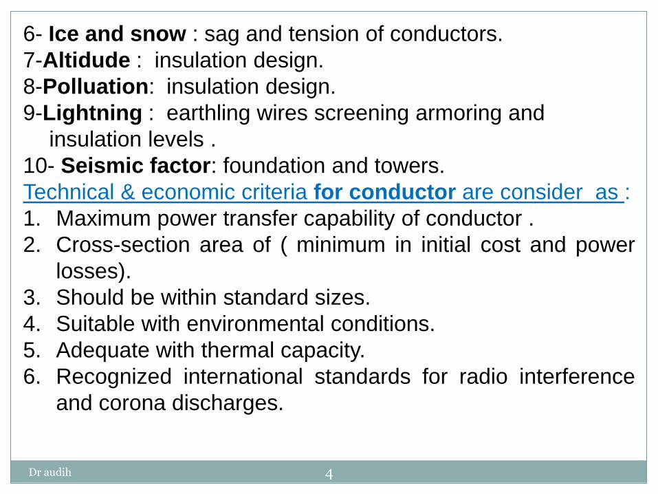
6- Ice and snow : sag and tension of conductors.
7-Altidude : insulation design.
8-Polluation: insulation design.
9-Lightning : earthling wires screening armoring and
insulation levels .
10- Seismic factor: foundation and towers.
Technical & economic criteria for conductor are consider as :
1. Maximum power transfer capability of conductor .
2. Cross-section area of ( minimum in initial cost and power
losses).
3. Should be within standard sizes.
4. Suitable with environmental conditions.
5. Adequate with thermal capacity.
6. Recognized international standards for radio interference
and corona discharges.

Dr audih 5
The conductors of OHL may be:
ACSR: Aluminum Conductor Steel Reinforced.
AAAC: All Aluminum Alloy Conductor.
ACAR: Aluminum Conductor Alloy Reinforced.
AACSR: All Aluminum Conductor Steel Reinforced.
AAC: All Aluminum Conductor.
Widely ACSR is used in TL since it’s mechanical strength and effectiveness cost. But in distribution widely uses is AAAC.
Aluminum provides the necessary conductivity while steel
provides the necessary mechanical strength. electrolytic action (corrosion) is reduce by adding a layer of grease
between aluminum and steel
(The steel strands are galvanized with zinc).
The insulation material used for conductor are polyvinylchloride
(PVC), linear polyethylene (PE) or cross-linked polyethylene
(XLPE).
The line conductors of TL types are based on animals names.

Dr audih 6
Example Zebra ACSR
This become with 54 Al strands surrounding seven steel strands, all
strands of diameter d= 3.18 mm. is designated 54/7/3.18;
aluminium area = 428.9 mm2, steel area = 55.6 mm2, and described
as having a nominal aluminium area of 400 mm2
Diameter of each strand

Dr audih 7
OVERHEAD POWER LINES conductors, network and environmental constraints - proprietary document
Dr audih 8
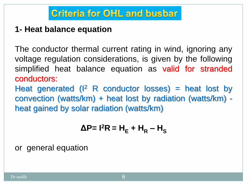
1- Heat balance equation
The conductor thermal current rating in wind, ignoring any
voltage regulation considerations, is given by the following
simplified heat balance equation as valid for stranded
conductors:
Heat generated (I2 R conductor losses) = heat lost by
convection (watts/km) + heat lost by radiation (watts/km) -
heat gained by solar radiation (watts/km)
ΔP= I2R = HE + HR – HS
or general equation
Dr audih 9
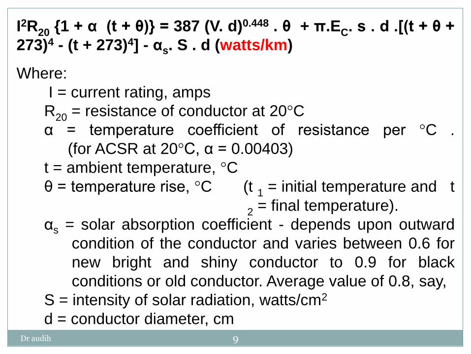
I2R20 {1 + α (t + θ)} = 387 (V. d)0.448 . θ + π.EC. s . d .[(t + θ +
273)4 - (t + 273)4] - αs. S . d (watts/km)
Where:
I = current rating, amps
R20 = resistance of conductor at 20°C
α = temperature coefficient of resistance per °C .
(for ACSR at 20°C, α = 0.00403)
t = ambient temperature, °C
θ = temperature rise, °C (t 1 = initial temperature and t
2 = final temperature).
αs = solar absorption coefficient - depends upon outward
condition of the conductor and varies between 0.6 for
new bright and shiny conductor to 0.9 for black
conditions or old conductor. Average value of 0.8, say,
S = intensity of solar radiation, watts/cm2
d = conductor diameter, cm

Dr audih 10
V = wind velocity normal to conductor, cm/s
Ec = emissivity of conductor- differs with conductor surface
brightness. Typical values are 0.3 for new bright and
0.9 for black aluminum, ACSR or AAAC conductor.
Average value =0.6, say.
s = Stefan-Boltzmann's constant = 5.7 x 10⁻⁸ watts/m2
π = 3.41 592 654 For design purposes 0.5 or 0.6 m/s wind speeds are often
taken. Higher wind speeds would lead to higher ratings.
In practice, the heat balance is a highly complex process but
the above equation is adequate for calculation purposes.
Dr audih 11
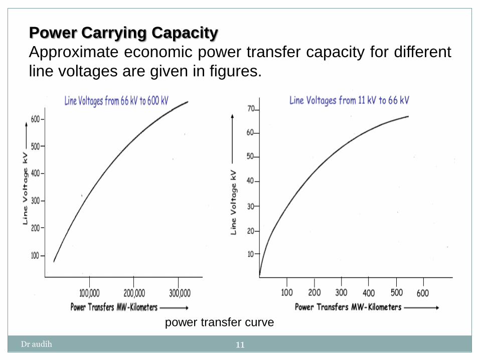
Power Carrying Capacity
Approximate economic power transfer capacity for different
line voltages are given in figures.
power transfer curve
Dr audih 12
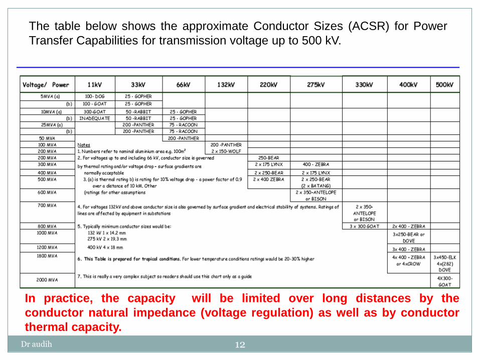
The table below shows the approximate Conductor Sizes (ACSR) for Power
Transfer Capabilities for transmission voltage up to 500 kV.
In practice, the capacity will be limited over long distances by the
conductor natural impedance (voltage regulation) as well as by conductor
thermal capacity.

Dr audih 13
Depending upon the required electrical load transfer, the
number of overhead line conductors of a particular type (used
per phase) will vary. Conductor configurations are given in
figure.
Dr audih 14
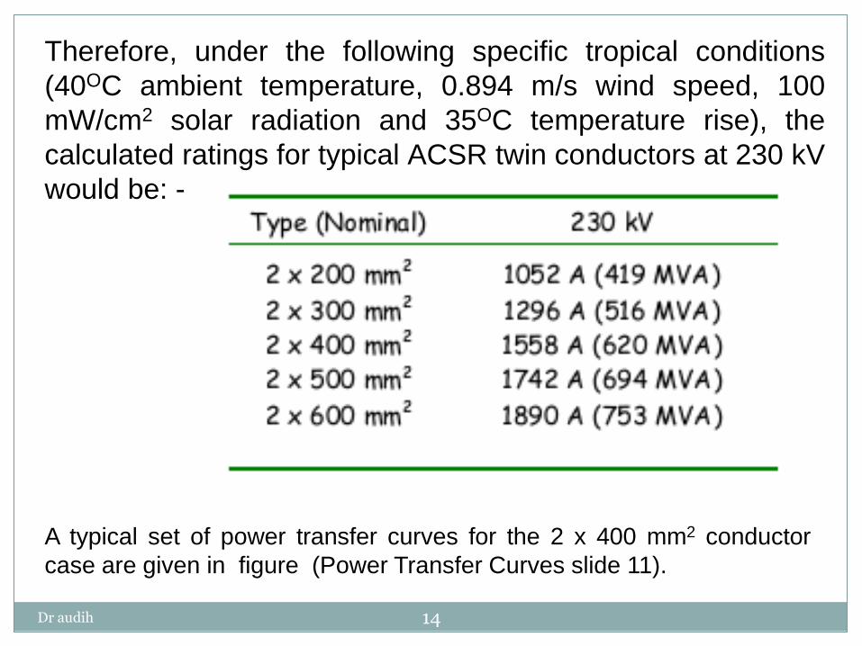
Therefore, under the following specific tropical conditions
(40OC ambient temperature, 0.894 m/s wind speed, 100
mW/cm2 solar radiation and 35OC temperature rise), the
calculated ratings for typical ACSR twin conductors at 230 kV
would be: -
A typical set of power transfer curves for the 2 x 400 mm2 conductor
case are given in figure (Power Transfer Curves slide 11).

Dr audih 15
2- Corona discharge
High voltage gradients surrounding conductors (above about
18 kV /cm) will lead to a breakdown of the air around the
conductor surface known as corona discharge. The effect is
more pronounced at high altitudes. Generally, the breakdown
strength of air is approximately 31 kV peak/cm or 22 kV
rms/cm. This is a useful guide for the selection of a
conductor diameter or conductor bundle arrangement
equivalent diameter.
At higher voltage levels, 400kV and above, interferences
due to the corona effect can be determining the physical
size of the conductor rather than the thermal rating
characteristic.
Increasing the conductor diameter may be necessary in
order to reduce the surface to acceptable levels.
Dr audih 16
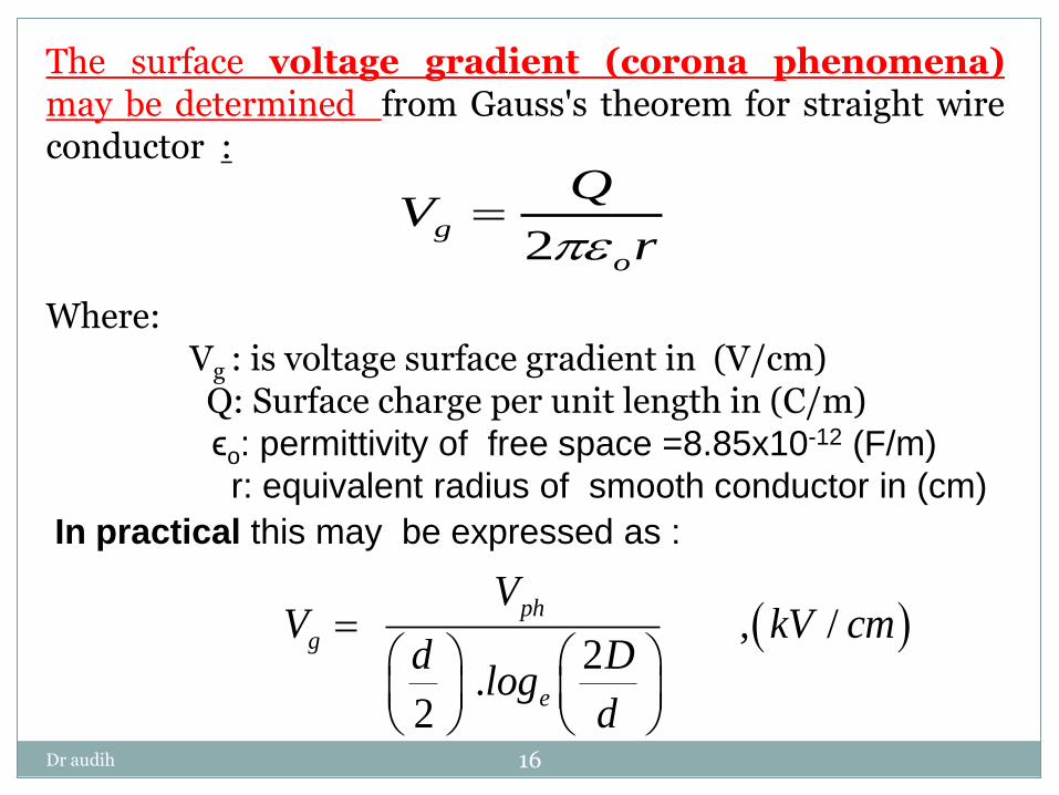
The surface voltage gradient (corona phenomena) may be determined from Gauss's theorem for straight wire conductor : Where: Vg : is voltage surface gradient in (V/cm) Q: Surface charge per unit length in (C/m) ϵo: permittivity of free space =8.85x10⁻¹² (F/m)
r: equivalent radius of smooth conductor in (cm)
2g
o
QV
r
In practical this may be expressed as :
, / 2
.2
ph
g
e
VV kV cm
d Dlog
d
Dr audih 17
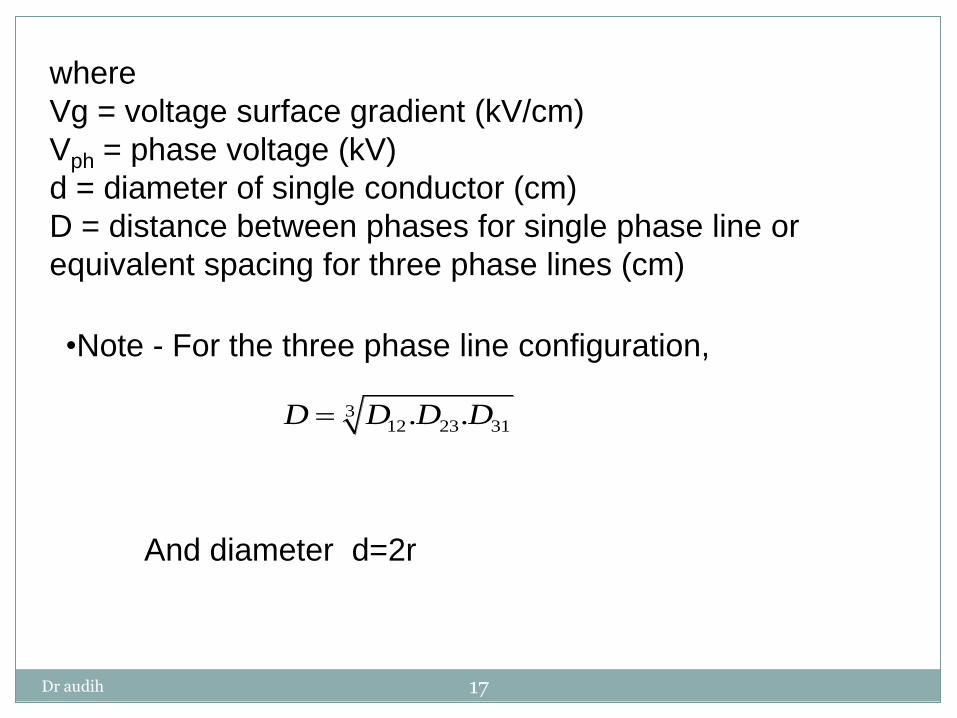
where
Vg = voltage surface gradient (kV/cm)
Vph = phase voltage (kV)
d = diameter of single conductor (cm)
D = distance between phases for single phase line or
equivalent spacing for three phase lines (cm)
•Note - For the three phase line configuration,
And diameter d=2r
312 23 31. .D D D D

Dr audih 18
3
3
3
2 2
( )
( )
(D d )
10.940
c
GMD double circuit symmetrical
D d D e D f
D d D
a a a
b b b
c c
a
e D f
D e D f
D e ad de and so
m
3 . .ab bc ac
GMD single circuit unsymmetrical
D D D
3
23 (14) (28) 17.6388
. .
9m
ab bc acDGMD flat D D
Dr audih 19
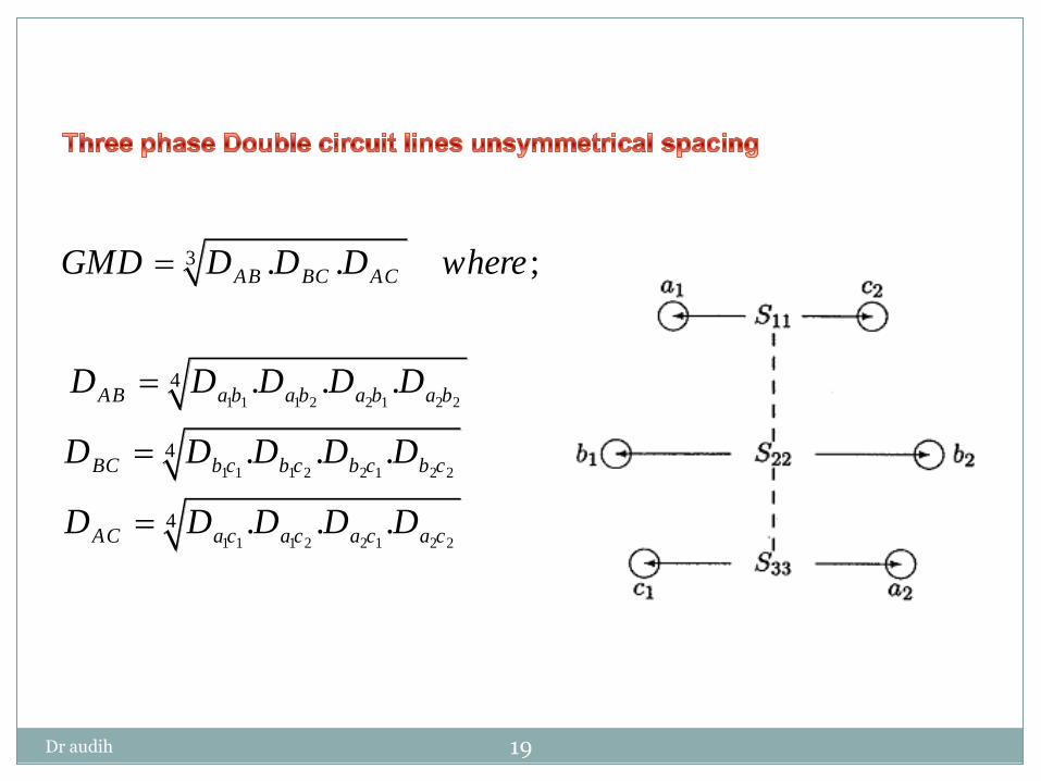
1 1 1 2 2 1 2 2
1 1 1 2 2 1 2 2
1 1 1 2 2 1 2 2
3
4
4
4
. . ;
. . .
. . .
. . .
AB BC AC
AB a b a b a b a b
BC b c b c b c b c
AC a c a c a c a c
GMD D D D where
D D D D D
D D D D D
D D D D D
Dr audih 20
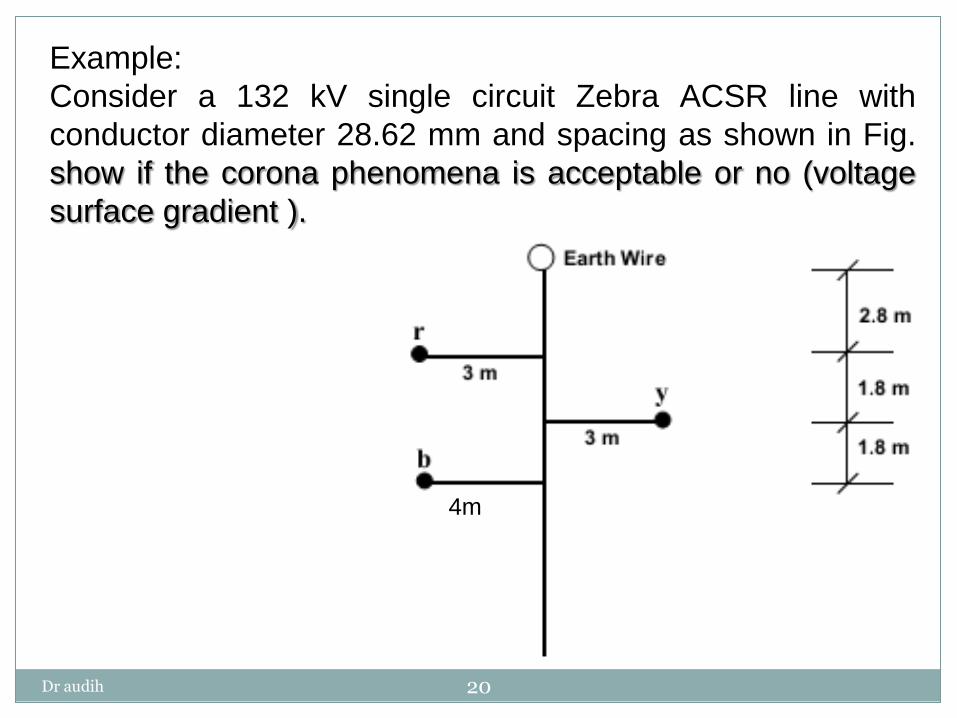
Example:
Consider a 132 kV single circuit Zebra ACSR line with
conductor diameter 28.62 mm and spacing as shown in Fig.
show if the corona phenomena is acceptable or no (voltage
surface gradient ).
4m

Dr audih 21
Solution: 2 2 2
2 2 2
2 2 2
3
6 1.8 6.26
7 1.8 7.23
1 3.6 3.74
. . 5.53 553
ry
yb
br
ry yb br
D m
D m
D m
D D D D m cm
132 / 3 8.94 /
2.86 2 553 .
2 2.86
g
e
V kV cm
log
8.94 is within the 18kV criteria and this is acceptable
Note : If the value result is high than 18kV we have two alternatives :
a)Increase the conductor diameter.
b)Increase the spacing distance

Dr audih 22
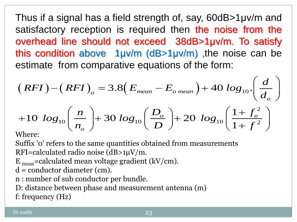
3- Radio frequency interference (RFI)
The noise is measured in decibels(dB) . Acceptable noise levels depend upon the quality of service required and is described in terms of an acceptable signal-to-noise or signal plus noise-to-noise ratio. Some reception classifications are given in table :
Dr audih 23
Thus if a signal has a field strength of, say, 60dB>1μv/m and
satisfactory reception is required then the noise from the
overhead line should not exceed 38dB>1μv/m. To satisfy
this condition above 1μv/m (dB>1μv/m) ,the noise can be
estimate from comparative equations of the form:
Where: Suffix '0' refers to the same quantities obtained from measurements RFI=calculated radio noise (dB>1μV/m. E mean=calculated mean voltage gradient (kV/cm). d = conductor diameter (cm). n : number of sub conductor per bundle. D: distance between phase and measurement antenna (m) f: frequency (Hz)
10
2
10 10 10 2
3.8 40 .
110 30 20
1
mean o meano
o
o o
o
dRFI RFI E E log
d
D fnlog log log
n D f
Dr audih 24
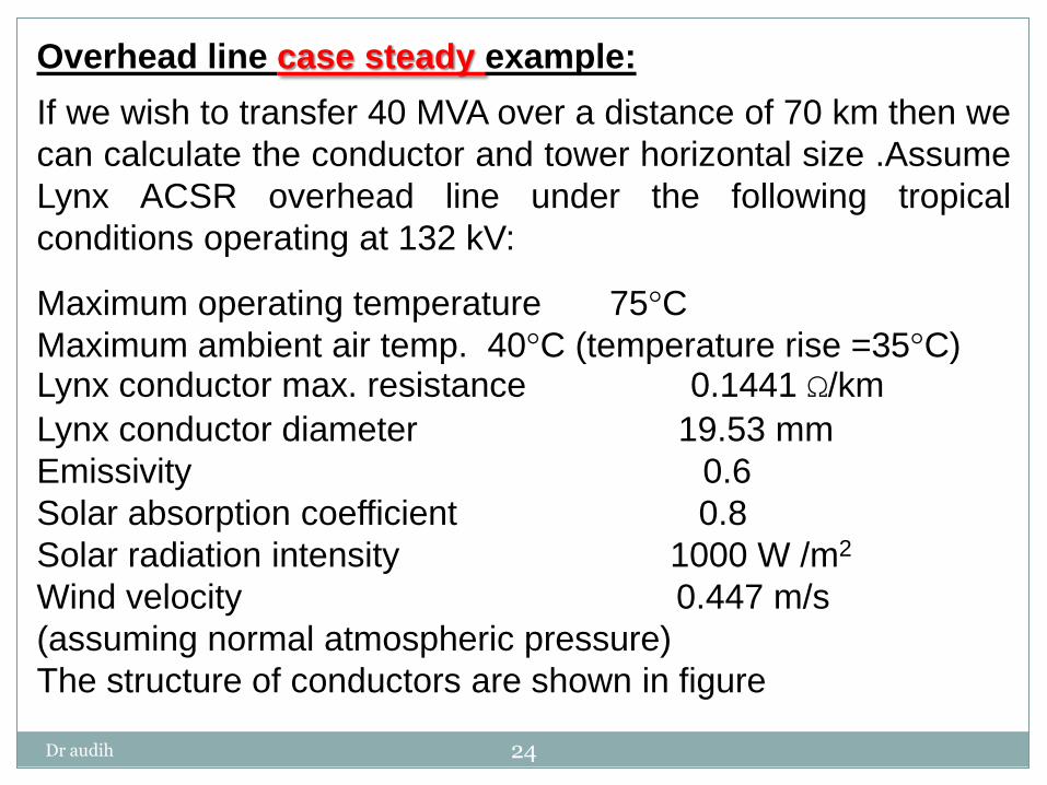
Overhead line case steady example:
If we wish to transfer 40 MVA over a distance of 70 km then we
can calculate the conductor and tower horizontal size .Assume
Lynx ACSR overhead line under the following tropical
conditions operating at 132 kV:
Maximum operating temperature 75°C
Maximum ambient air temp. 40°C (temperature rise =35°C) Lynx conductor max. resistance 0.1441 Ω/km
Lynx conductor diameter 19.53 mm
Emissivity 0.6
Solar absorption coefficient 0.8
Solar radiation intensity 1000 W /m2
Wind velocity 0.447 m/s
(assuming normal atmospheric pressure)
The structure of conductors are shown in figure

Dr audih 25
Cheek if the conductor propose and spacing are acceptable..

Dr audih 26
Solution:
Load current at 132kV for 40MVA power transfer and unity
power factor is
The conductor thermal rating capability is first determined,
ignoring any voltage drop considerations, by comparing the
175 A load current requirement and the rating of the
conductor derived from the heat balance equation the
thermal capacity must be greater than load current to
accepted this design
2 4 0.448 4 4
2 1. 13.8 10 .( ).(v.d) . . . .( ) . . ,( )/C s Watts cI R E s d T T S d m
6
3
40 10175A
3. .cos 3 132 10 1L
L
PI
V
Note if the voltage level is 400kV and above starting with corona calculation
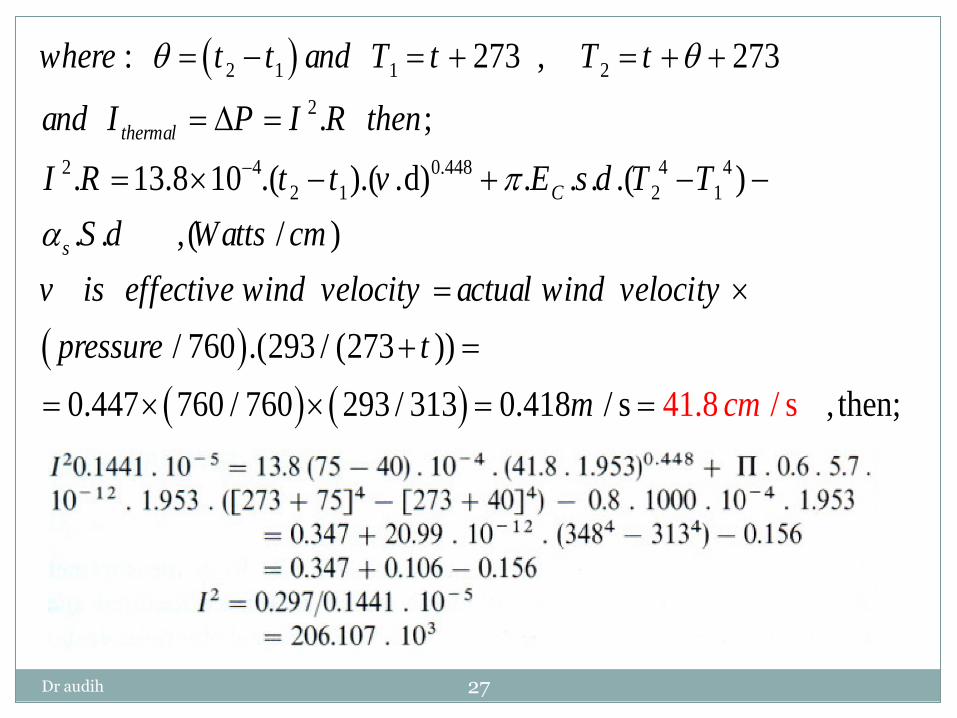
Dr audih 27
2 1 1
2 4 0.448 4 4
2
2
2
1 2 1
:
. 13.8 10 .( ).( .d) . . . .( )
. . ,(
273 , 273
. ;
/ 760 . 293 /
/ )
( (27 ))3
t er
C
al
s
h m
where t t and T
I R t t v E s d
t T t
and I P I R then
v is effective wind velocity actual wind velocity
pressure
T T
S d Watts
t
cm
0.447 760 / 760 293 / 313 0.418 / s 41.8 / , then;scmm

Dr audih 28
The conductor type is therefore is adequate on thermal
considerations for the load required.
3 454 A
and since I (454) (175)
206.107 10
thermal LoadI
The next check is then made for any corona discharge limitations
.
2 .
2
ph
g
e
VV
d Dlog
d

Dr audih 29
2 2 2
2 2 2
3
4.5 1 4.61
4.5 1 4.61
9
. . 5.76 576
ry
yb
br
ry yb br
D m
D m
D m
D D D D m cm
132 / 3 12.22 /
1.953 2 576 .
2 1.953
g
e
V kV cm
log
Which is within the 18kV/cm criteria and Lynx conductor is
acceptable for this design

Dr audih 30
If capacitive reactance is ignored the voltage drop, Vd, for a
line length, l, is calculated from the usual formula: -
If the load at the receiving end is given
in kVA, then for a three phase system
the load current as:
The main practical problem is now to obtain accurate values
for the line reactance.
1( ) ( ( )) I R j( L )L CV IZ I R jX I R j X X
C
4-Voltage drop calculation:
Z X
R
Φ
Dr audih 31
It is useful to introduce the concept of kVA km for a given voltage drop
for a variety of overhead line configurations and different conductors.
For a 10% voltage drop the.
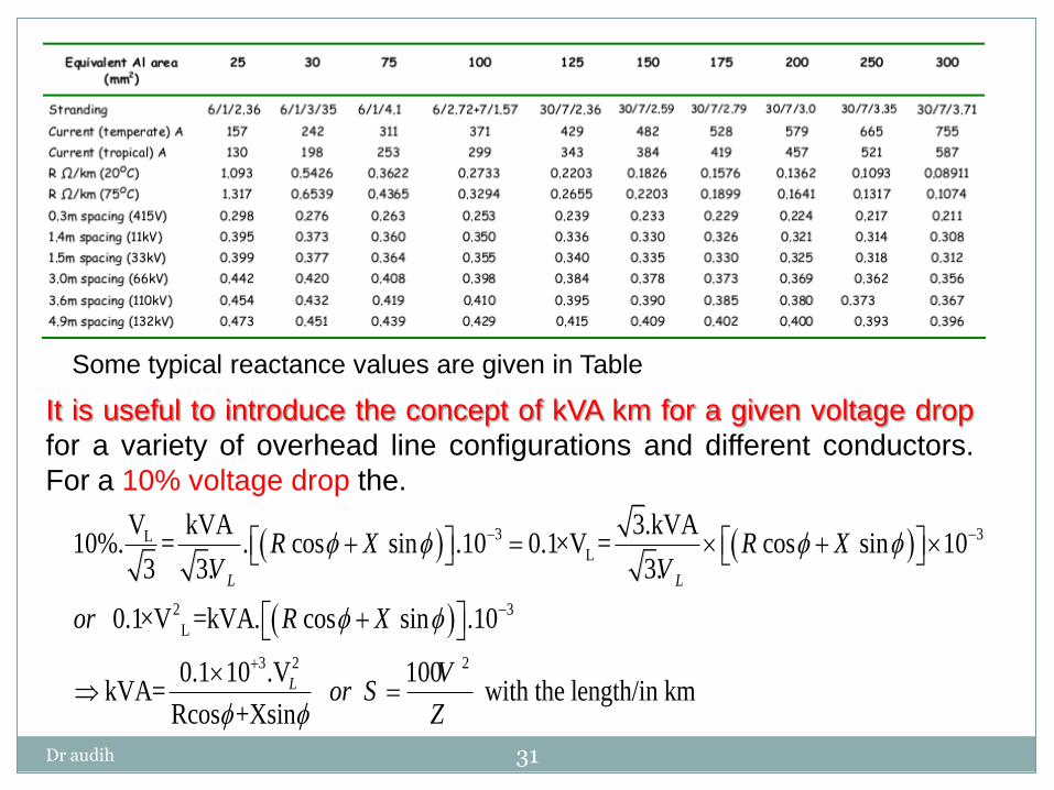
Some typical reactance values are given in Table
3 3LL
2 3
L
3 2 2
V kVA 3.kVA10%. = . cos sin .10 0.1×V = cos sin 10
3 3. 3.
0.1×V =kVA. cos sin .10
0.1 10 .V 100kVA= with the length/in km
Rcos +Xsin
L L
L
R X R XV V
or R X
Vor S
Z

Dr audih 32
Skin Effect
When a conductor is carrying direct current (DC), this current is uniformly distributed over the whole cross-section of the conductor. But is case of (AC) the current flowing through the conductor is not distributed uniform through cross section , it is concentrate near the surface of the conductor as shown in Fig. This is known as skin effect.
Due to skin effect: the effective cross section area of the conductor through which current flows is reduced. Then the resistance of the conductor is slightly increased when carrying an alternating current.
Dr audih 33
The skin effect depends upon the following factors : i. Nature of material ii. Diameter of wire−increases with the diameter of wire. iii. Frequency − increases with the increase in frequency. iv. Shape of wire − less for stranded conductor than the
solid conductor. It may be noted that skin effect is negligible when the supply
frequency is low (< 50 Hz) and conductor diameter is small
(< 1cm).
Dr audih 34
Earth Wires
Where there is a risk of direct lightning strike to the phase
conductors, transmission lines are provided with overhead
earth (or ground) wires to shield them and also to provide a
low impedance earth return path.
Note that today’s earth wires on new circuits are equipped in
construction with an optical fiber in the center of the bundle.
This is known as optical fibre ground wire (OPGW) and is
used for data communications for protection relaying,
Supervisory Control and Data Acquisition (SCADA), and other
utility data transmission requirements such as power line
carrier (PLC).
The degree of shielding of the OHL phase conductors from
lightning strikes is determined by the shielding angle afforded
by the earth wire(s) running over the line.
Dr audih 35
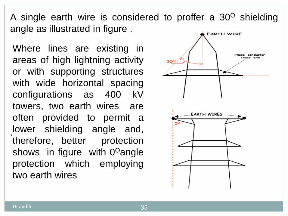
A single earth wire is considered to proffer a 30O shielding
angle as illustrated in figure .
.
Where lines are existing in
areas of high lightning activity
or with supporting structures
with wide horizontal spacing
configurations as 400 kV
towers, two earth wires are
often provided to permit a
lower shielding angle and,
therefore, better protection
shows in figure with 0Oangle
protection which employing
two earth wires
Related Documents


