Code No: R059010203 Set No. 1 I B.Tech Regular Examinations, Ma y/Jun 2006 ELECTRICAL CIRCUITS ( Common to Electrical & Electronic Engineering, Electronics & Control Engineering and Instrumentation & Control Engineering) Time: 3 hours Max Marks: 80 Answer any FIVE Questions All Questions carry equal marks 1. (a) Find the voltage to be applied across AB in order to dri ve a current of 5A into the circuit by using star-delta transformation. Refer figure 1. Figure 1: (b) Usi ng Kirchoff’s current law, find the values of the curren ts i 1 and i 2 in the circuit shown in figure 2. [8+8] Figure 2: 2. (a) Define the following: i. Self inductance ii. Mutual Inductance iii. Static Induced e.m.f iv. Dynami cally induced e.m.f. (b) Derive the rela tion shi p betw een the self, mutual induct ances and coefficien t of coupling. 1 of 4

Welcome message from author
This document is posted to help you gain knowledge. Please leave a comment to let me know what you think about it! Share it to your friends and learn new things together.
Transcript

8/4/2019 Electrical Circuits Analysis 3
http://slidepdf.com/reader/full/electrical-circuits-analysis-3 1/18
Code No: R059010203 Set No. 1
I B.Tech Regular Examinations, May/Jun 2006ELECTRICAL CIRCUITS
( Common to Electrical & Electronic Engineering, Electronics & ControlEngineering and Instrumentation & Control Engineering)
Time: 3 hours Max Marks: 80Answer any FIVE Questions
All Questions carry equal marks
1. (a) Find the voltage to be applied across AB in order to drive a current of 5Ainto the circuit by using star-delta transformation. Refer figure 1.
Figure 1:
(b) Using Kirchoff’s current law, find the values of the currents i1 and i2 in thecircuit shown in figure 2. [8+8]
Figure 2:
2. (a) Define the following:
i. Self inductance
ii. Mutual Inductance
iii. Static Induced e.m.f
iv. Dynamically induced e.m.f.(b) Derive the relationship between the self, mutual inductances and coefficient
of coupling.
1 of 4
8/4/2019 Electrical Circuits Analysis 3
http://slidepdf.com/reader/full/electrical-circuits-analysis-3 2/18
Code No: R059010203 Set No. 1
(c) Two similar coils connected in series gave a total inductance of 600 mH andwhen one of the coil is reversed, the total inductance is 300mH. Determine themutual inductance between the coils and coefficient of coupling? [6+6+4]
3. (a) Bring out the differences between series and parallel resonance?
(b) A series RLC circuit consists of resistance R = 20Ω, inductance, L=0.01Hand capacitance, C = 0.04 µF. Calculate the frequency at resonance. If a10 Volts of frequency equal to the frequency of resonance is applied to thiscircuit, calculate the values of V C and V L across C and L respectively. Findthe frequencies at which these voltages V C and V L are maximum? [6+10]
4. (a) Three impedances each of (3-j4) Ω is connected in delta connection across a
3-φ, 230V balanced supply. Calculate the line and phase currents in the ∆connected load and the power delivered to the load?
(b) In power measurement of 3-φ load connected by 3-φ supply by two wattmeter
method, prove that tan θ = −√ 3(w1−w2)
(w1+w2)for leading power factor loads. [8+8]
5. (a) For the circuit shown in figure 3, draw the graph and indicate tree.
i. Branch
ii. Node
iii. Degree of a node
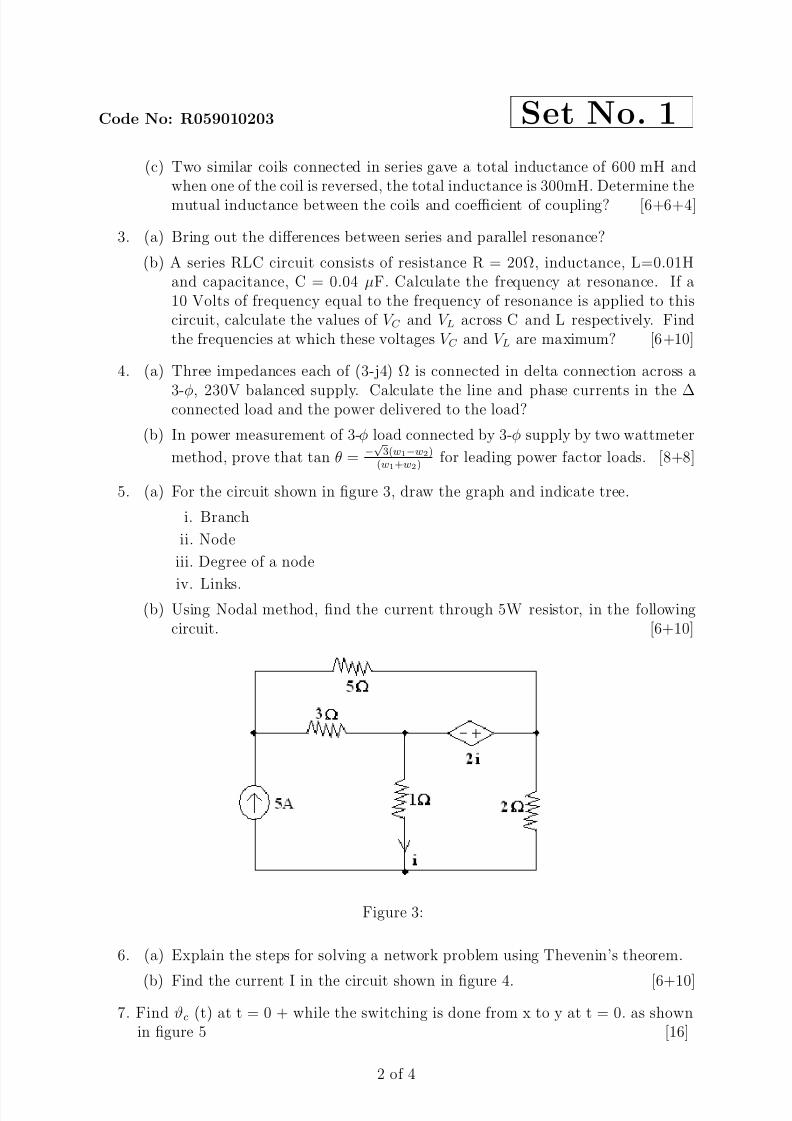
iv. Links.(b) Using Nodal method, find the current through 5W resistor, in the following
circuit. [6+10]
Figure 3:
6. (a) Explain the steps for solving a network problem using Thevenin’s theorem.
(b) Find the current I in the circuit shown in figure 4. [6+10]
7. Find ϑc (t) at t = 0 + while the switching is done from x to y at t = 0. as shownin figure 5 [16]
2 of 4

8/4/2019 Electrical Circuits Analysis 3
http://slidepdf.com/reader/full/electrical-circuits-analysis-3 3/18
Code No: R059010203 Set No. 1
Figure 4:
Figure 5:
Figure 6:
3 of 4

8/4/2019 Electrical Circuits Analysis 3
http://slidepdf.com/reader/full/electrical-circuits-analysis-3 4/18
Code No: R059010203 Set No. 1
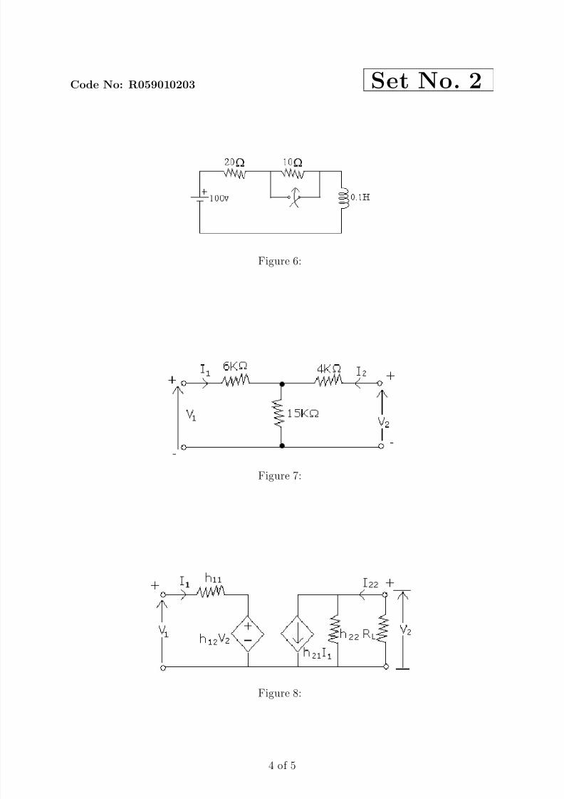
8. (a) Determine the Z-parameter of the network shown in figure 6.
(b) The y-parameters of a two port network are y11=0.6 mho, y22=1.2 mho andy12=-0.3 mho.
i. Determine the ABCD Parameters and
ii. Equivalent Π network. [8+8]
4 of 4

8/4/2019 Electrical Circuits Analysis 3
http://slidepdf.com/reader/full/electrical-circuits-analysis-3 5/18
Code No: R059010203 Set No. 2
I B.Tech Regular Examinations, May/Jun 2006ELECTRICAL CIRCUITS
( Common to Electrical & Electronic Engineering, Electronics & ControlEngineering and Instrumentation & Control Engineering)
Time: 3 hours Max Marks: 80Answer any FIVE Questions
All Questions carry equal marks
1. (a) For the circuit shown in figure 1, find the current through 20Ω resistor?
Figure 1:
(b) Reduce the network shown in figure 2, to a single loop network by successivesource transformation, to obtain the current in the 12Ω resistor. [8+8]
Figure 2:
1 of 5

8/4/2019 Electrical Circuits Analysis 3
http://slidepdf.com/reader/full/electrical-circuits-analysis-3 6/18
Code No: R059010203 Set No. 2
2. (a) Write short notes on dot convention used in magnetically coupled coils.
(b) In the network shown in figure 3, L1=1H, L2=2H, M=1.2H. Assuming theinductance coils to be ideal, find the amount of energy stored after 0.1 see of the circuit connected to a d.c.source of 10V. [6+10]
Figure 3:
3. (a) Explain the concept of
i. Susceptance and
ii. Admittance
(b) An inductive coil takes 10A and dissipates 1000 watts when connected to asupply of 250v, 25Hz. Calculate.
i. the impedance
ii. the effective resistance
iii. reactance
iv. the inductance
v. power factor. Also, Draw the vector diagram. [6+10]
4. (a) A balanced 3-ph star connected load of 150 Kw takes a leading current of 100A with a line voltage of 1100 V, 50Hz. Find the circuit constants of theload per phase?
(b) Three equal star connected inductors takes 8Kw at P.f of 0.8 when connected
to 460V, 3-φ, 3 wire supply. Find the line currents, if one conductor is shortcircuited. [6+10]
5. (a) Define the following and explain by taking an example.
i. Node
ii. Tree
iii. Sub graph
iv. Loop
v. Links
vi. Directed graph.(b) Find the fundamental tie-set and cut-set matrix for the graph and for the tree
shown in the figure 4. [9+7]
2 of 5

8/4/2019 Electrical Circuits Analysis 3
http://slidepdf.com/reader/full/electrical-circuits-analysis-3 7/18
Code No: R059010203 Set No. 2
Figure 4:
6. (a) State and explain compensation theorem.
(b) In the network shown in figure 5, find the value of Z L so that the powertransfer from the source is maxi mum. Also find P max. [8+8]
Figure 5:
7. (a) A dc voltage of 100V is applied in the circuit shown in figure 6 and the switchis kept open. The switch K is closed at t = 0. Find the complete expressionfor the current.
(b) A dc voltage of 20V is applied in a RL circuit where R = 5Ω and L = 10H.Find [8+8]
i. The time constant
ii. The maximum value of stored energy.
8. (a) Find the Z-parameters for the network shown in figure 7.
(b) For the h parameter equivalent network shown in figure 8 find the voltage gainload resistance is RL. [6+10]
3 of 5
8/4/2019 Electrical Circuits Analysis 3
http://slidepdf.com/reader/full/electrical-circuits-analysis-3 8/18
Code No: R059010203 Set No. 2
Figure 6:
Figure 7:
Figure 8:
4 of 5

8/4/2019 Electrical Circuits Analysis 3
http://slidepdf.com/reader/full/electrical-circuits-analysis-3 9/18
Code No: R059010203 Set No. 2
5 of 5

8/4/2019 Electrical Circuits Analysis 3
http://slidepdf.com/reader/full/electrical-circuits-analysis-3 10/18
Code No: R059010203 Set No. 3
I B.Tech Regular Examinations, May/Jun 2006ELECTRICAL CIRCUITS
( Common to Electrical & Electronic Engineering, Electronics & ControlEngineering and Instrumentation & Control Engineering)
Time: 3 hours Max Marks: 80Answer any FIVE Questions
All Questions carry equal marks
1. (a) For the circuit shown in figure 1, find the current through 20Ω resistor?
Figure 1:
(b) Reduce the network shown in figure 2, to a single loop network by successivesource transformation, to obtain the current in the 12Ω resistor. [8+8]
Figure 2:
1 of 5

8/4/2019 Electrical Circuits Analysis 3
http://slidepdf.com/reader/full/electrical-circuits-analysis-3 11/18
Code No: R059010203 Set No. 3
2. (a) Explain
i. Statically induced e.m.f andii. Dynamically induced e.m.f
(b) The combined inductance of two coils connected in series is 0.6H or 0.1H,depending upon the relative directions of the currents in the coils. If one of the coils when isolated has a self inductance of 0.2H, Calculate
i. Mutual inductance, and
ii. The Coefficient of coupling.
(c) Explain the terms
i. MMF
ii. Reluctance. [6+6+4]
3. (a) Draw the current, impedance and admittance loci for an R L series circuithaving fixed resistance but variable reactance.
(b) figure 3 shows a series parallel circuit. Find
i. admittance of each branch
ii. admittance between points b and g.
iii. impedance between points b and g.
iv. total circuit impedance
v. total current and power factorvi. currents in each branch. [6+10]
Figure 3:
4. (a) Three identical resistances are connected in a star fashion against a balancedthree phase voltage supply. If one of the resistance is removed, how much
power is to be reduced?(b) A 3-phase load has a resistance of 10Ω in each phase and is connected in
i. star and
2 of 5

8/4/2019 Electrical Circuits Analysis 3
http://slidepdf.com/reader/full/electrical-circuits-analysis-3 12/18
Code No: R059010203 Set No. 3
ii. delta against a 400V, 3-phase supply. Compare the power consumed inboth the cases.
(c) What is the difference between RYB phase sequence with RBY phase se-quence? [6+6+4]
5. (a) Define the following and explain by taking an example.
i. Branch
ii. Node
iii. Path
iv. Sub graph
v. Tree
vi. Degree of a node.
(b) Draw the oriented graph of the network shown in figure 4 and write the cutset matrix. [9+7]
Figure 4:
6. (a) State and explain the Millmann’s theorem.
(b) Find the current in the 6Ω resistor using Superposition theorem. as shown infigure 5 [6+10]
7. (a) A dc voltage of 100V is applied in the circuit shown in figure 6 and the switchis kept open. The switch K is closed at t = 0. Find the complete expressionfor the current.
(b) A dc voltage of 20V is applied in a RL circuit where R = 5Ω and L = 10H.Find [8+8]
i. The time constant
ii. The maximum value of stored energy.
8. (a) In a T network shown in figure 7, Z 1 = 20o, Z 2 = 5 − 90o, Z 3 = 390o, findthe Z-parameters.
3 of 5

8/4/2019 Electrical Circuits Analysis 3
http://slidepdf.com/reader/full/electrical-circuits-analysis-3 13/18
Code No: R059010203 Set No. 3
Figure 5:
Figure 6:
Figure 7:
4 of 5

8/4/2019 Electrical Circuits Analysis 3
http://slidepdf.com/reader/full/electrical-circuits-analysis-3 14/18
Code No: R059010203 Set No. 3
(b) Z-parameters for a two port network are given as Z 11=25Ω, Z 12=Z 21=20Ω,Z 22=50Ω. Find the equivalent T-network. [8+8]
5 of 5

8/4/2019 Electrical Circuits Analysis 3
http://slidepdf.com/reader/full/electrical-circuits-analysis-3 15/18
Code No: R059010203 Set No. 4
I B.Tech Regular Examinations, May/Jun 2006ELECTRICAL CIRCUITS
( Common to Electrical & Electronic Engineering, Electronics & ControlEngineering and Instrumentation & Control Engineering)
Time: 3 hours Max Marks: 80Answer any FIVE Questions
All Questions carry equal marks
1. (a) Explain
i. KCL
ii. KVLiii. Practical current source
iv. Practical voltage source.
(b) A 20V battery with an internal resistance of 5 ohms is connected to a resistorof x ohms. If an additional resistance of 6Ω is connected across the battery,find the value of x, so that the external power supplied by the battery remainthe same. [8+8]
2. (a) Explain the following terms:-
i. Magnetic circuit
ii. Permeability
iii. Magneto motive force
iv. Reluctance.
(b) A cast steel structure is made of a rod of square section 2.5cm × 2.5cm asshown in figure 1. What is the current that should be passed in a 500 turncoil on the left limb, so that a flux of 2.5mwb is made to pass in the rightlimb. Assume permeability as 750 and neglect leakage. [8+8]
Figure 1:
3. (a) Derive the expression for power in a1-φ A.c circuits.
1 of 4

8/4/2019 Electrical Circuits Analysis 3
http://slidepdf.com/reader/full/electrical-circuits-analysis-3 16/18
Code No: R059010203 Set No. 4
(b) In the circuit shown in figure 2, Calculate.
i. The total impedanceii. The total current
iii. Power factor
iv. The total S,P and Q
v. The total admittance. Also, draw vector diagram. [6+10]
Figure 2:
4. (a) Two resistors each of 100Ω are connected in series. The phases a and c of a three phase 400V supply are connected to the two ends and phase b isconnected to the junction of the two resistors. Find the line currents.
(b) Derive the expressions for wattmeter readings in two wattmeter method withbalanced star connected load. How do you calculate the power factor of thebalanced load from wattmeter readings? [8+8]
5. (a) Define the following and explain by taking an example.
i. Node
ii. Tree
iii. Sub graphiv. Loop
v. Links
vi. Directed graph.
(b) Find the fundamental tie-set and cut-set matrix for the graph and for the treeshown in the figure 3. [9+7]
6. (a) State and explain compensation theorem.
(b) In the network shown in figure 4, find the value of Z L so that the powertransfer from the source is maxi mum. Also find P max. [8+8]
7. In the figure 5, the switch is close at position 1 at t = 0. At t = 0.5 m sec. Theswitch is moved to position 2. Find the expression for the current in both theconditions and sketch the transient. [16]
2 of 4

8/4/2019 Electrical Circuits Analysis 3
http://slidepdf.com/reader/full/electrical-circuits-analysis-3 17/18
Code No: R059010203 Set No. 4
Figure 3:
Figure 4:
Figure 5:
3 of 4

8/4/2019 Electrical Circuits Analysis 3
http://slidepdf.com/reader/full/electrical-circuits-analysis-3 18/18
Code No: R059010203 Set No. 4
8. Determine Y-Parameters of the network shown in figure 6. [16]
Figure 6:
Related Documents