4 Electrical and Optical Properties As polymer materials have developed, their excellent and sometimes outstanding dielectric properties have guaranteed their widespread use as insulants in electrical and electronic engineering. In the nineteenth and early twentieth centuries electrical apparatus relied on wood, cotton sleeving, natural waxes and resins and later ebonite as insulating materials. Today a number of polymers including PTFE, PE, PVC, EP and MF offer an unrivalled combination of cost, ease of processing and electrical performance. These materials have played a most important part in the evolution of electrical components and equipment. Most electrical properties are determined largely by primary chemical structure, and are relatively insensitive to microstructure. In consequence the electrical behaviour of polymers is generally less varied than the mechanical behaviour. The same can be said of the optical properties, which nevertheless govern a variety of engineering end-uses. 4.1 Behaviour in a Steady (d.c.) Electric Field The electrical properties of a material may be investigated by considering its response to imposed electric fields of various strengths and frequencies, just as the mechanical properties may be defined through the response to static and cyclic stress. We consider first the behaviour of polymers in steady (d.c.) electric fields. Figure 4.1 shows the range of volume resistivity p found in electrical engineering materials. Polymers as a class have the very high electrical resistivity characteristic of insulators. To quote resistivities in this way implies that Ohm's law is obeyed and that the conduction current / = AE/p, where E is the electric field strength and A the cross-sectional area of the material. However, it is 100

Welcome message from author
This document is posted to help you gain knowledge. Please leave a comment to let me know what you think about it! Share it to your friends and learn new things together.
Transcript
4
Electrical and OpticalProperties
As polymer materials have developed, their excellent and sometimes outstanding
dielectric properties have guaranteed their widespread use as insulants in
electrical and electronic engineering. In the nineteenth and early twentieth
centuries electrical apparatus relied on wood, cotton sleeving, natural waxes and
resins and later ebonite as insulating materials. Today a number of polymers
including PTFE, PE, PVC, EP and MF offer an unrivalled combination of cost,
ease of processing and electrical performance. These materials have played a
most important part in the evolution of electrical components and equipment.
Most electrical properties are determined largely by primary chemical structure,
and are relatively insensitive to microstructure. In consequence the electrical
behaviour of polymers is generally less varied than the mechanical behaviour.
The same can be said of the optical properties, which nevertheless govern a
variety of engineering end-uses.
4.1 Behaviour in a Steady (d.c.) Electric Field
The electrical properties of a material may be investigated by considering its
response to imposed electric fields of various strengths and frequencies, just as
the mechanical properties may be defined through the response to static and
cyclic stress. We consider first the behaviour of polymers in steady (d.c.) electric
fields.
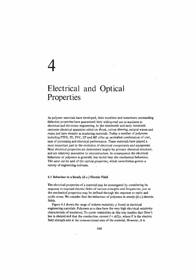
Figure 4.1 shows the range of volume resistivity p found in electrical
engineering materials. Polymers as a class have the very high electrical resistivity
characteristic of insulators. To quote resistivities in this way implies that Ohm's
law is obeyed and that the conduction current / = AE/p, where E is the electric
field strength and A the cross-sectional area of the material. However, it is
100
ELECTRICAL AND OPTICAL PROPERTIES 101
1 0 , 6 . •pinm) •
1012
- • ^ ^ PorcelainsH I Polymers
—- Diamond —g^ = Glass •
108-
Gutta-percha •Insulators
104'
Silicon
10°-Selenium Semiconductors
Germanium
io-4-
Graphite
TitaniumIron
1 0 - 8 . Copper, silver Conductors
Figure 4.1 Volume resistivity p of electrical engineering materials
difficult to measure steady d.c. conduction in high performance insulants such
as PTFE, where p may exceed 1016J2 m. The volume resistivity measured by
standard test methods increases steadily with time. One-minute values of p are
frequently quoted, but curves such as those of figure 4.2 showing how p changes
with time of electrification present the d.c. conduction behaviour more
Resistivity p
(12 m)
10 100 1000Time t (s)
Figure 4.2 Changes in volume resistivity p with elapsed time for selectedpolymers
102 POLYMER MATERIALS
satisfactorily. Conduction in the surface layers of a polymer material is often
sensitive to ambient humidity and surface contamination. The surface resistivity
is determined from the flow of current between two electrodes in contact with
one surface of a thin specimen of polymer material.
The extremely low values of current at typical working voltages implied by
the high values of p show the absence in polymers of any large number of charge
carriers such as exist in metals and to a less extent in semiconductors. The
valency electrons in polymer molecules (with a few exceptions) are localised in
covalent bonds between pairs of atoms. The small currents which are observed
to flow in weak fields arise from the movement of electrically charged species
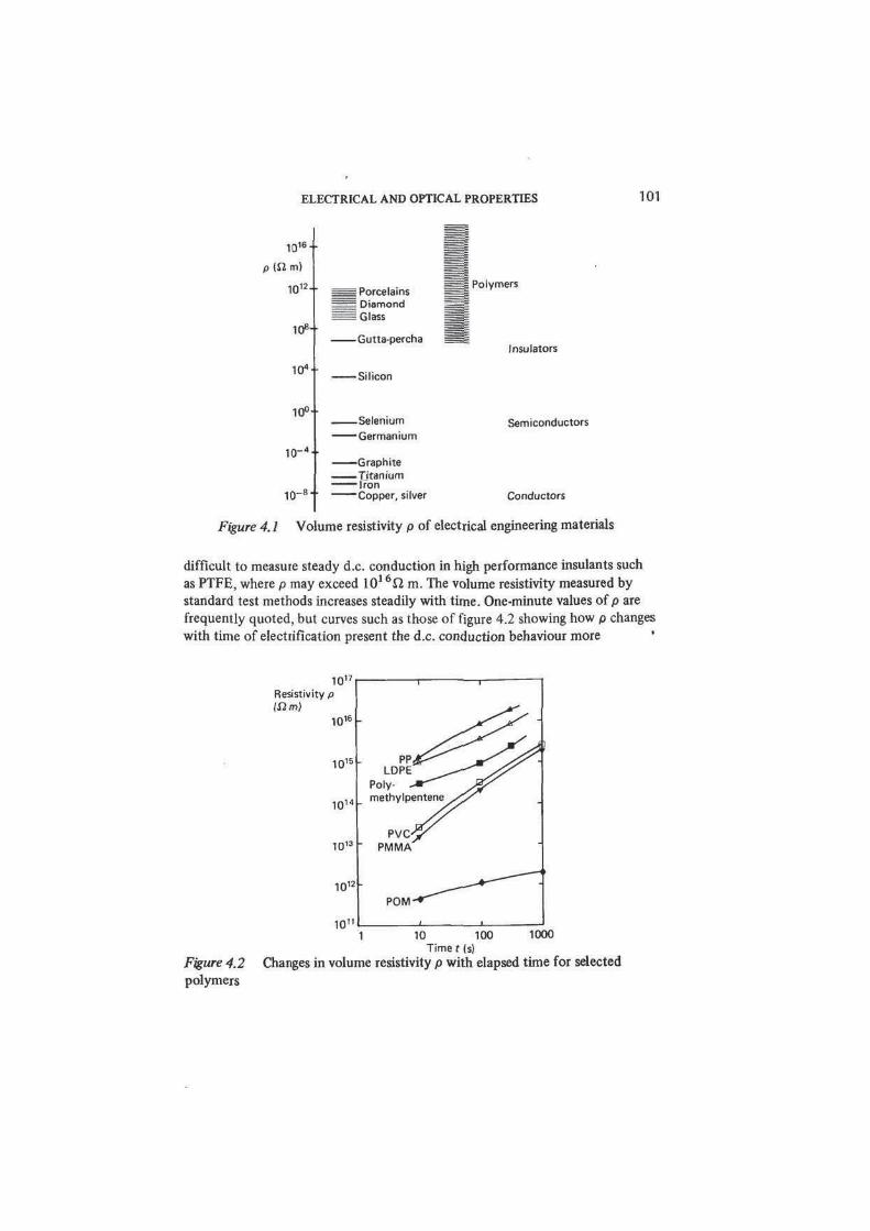
present as structural defects and impurities. The concentration of defects
increases as the temperature rises, so that the resistivity falls - figure 4.3(a).
Exposure to ionising radiation and absorption of water or plasticiser can also
lead to an increase in the concentration of charge carriers with an accompanying
increase in conductivity - figure 4.3(b)-
The high conductivity of graphite (figure 4.1) demonstrates that polymeric
materials are not invariably insulators. The conductivity of graphite (which is a
form of pure carbon) arises directly from its chemical and electronic structure.
In the solid the carbon atoms lie in parallel stacked layers - see figure 1.8(a).
Within each layer the C atoms are bonded in hexagonal rings to form a
continuous network of primary chemical bonds. However, a quarter of all the
valency electrons in such a fused ring structure are not localised between pairs
of atoms, but are delocalised, much as they are in metals, and are free to carry a
io1Brp
inmi
io1 4
-
1 0 1 3 -
101 2
-
1 0 " -
1 0 i o .
0 50 100 0 50 100
Temperature (°C) Relative humidity
(a) (b)
Figure 4.3 (a) Volume resistivity p of unplasticised PVC between 0 and 100 °C
(all values measured after 60 s electrification), (b) Steady-state volume resistivity
p of polyamides: dependence on relative humidity at room temperature
PA-610
PA-66PA-6
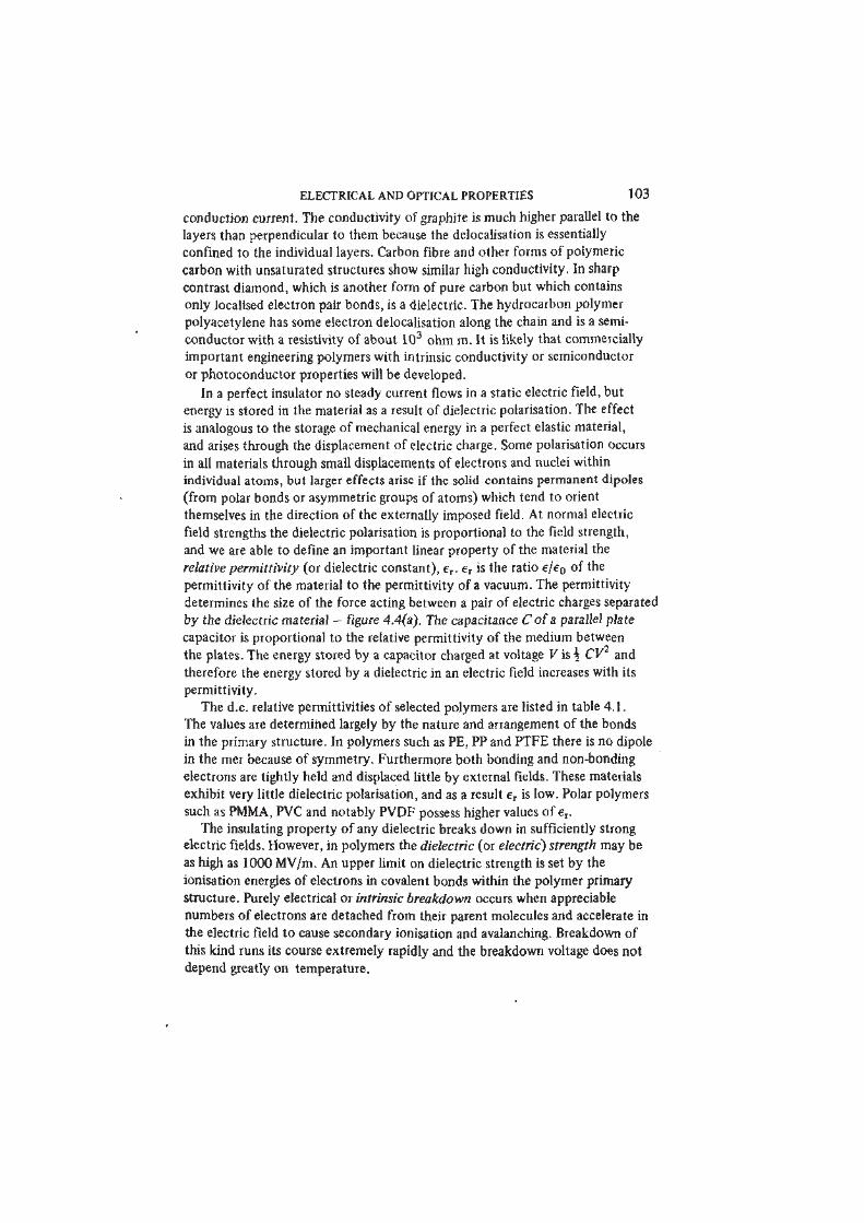
ELECTRICAL AND OPTICAL PROPERTIES 103
conduction current. The conductivity of graphite is much higher parallel to the
layers than perpendicular to them because the delocalisation is essentially
confined to the individual layers. Carbon fibre and other forms of polymeric
carbon with unsaturated structures show similar high conductivity. In sharp
contrast diamond, which is another form of pure carbon but which contains
only localised electron pair bonds, is a dielectric. The hydrocarbon polymer
polyacetylene has some electron delocalisation along the chain and is a semi-
conductor with a resistivity of about 103 ohm m. It is likely that commercially
important engineering polymers with intrinsic conductivity or semiconductor
or photoconductor properties will be developed.
In a perfect insulator no steady current flows in a static electric field, but
energy is stored in the material as a result of dielectric polarisation. The effect
is analogous to the storage of mechanical energy in a perfect elastic material,
and arises through the displacement of electric charge. Some polarisation occurs
in all materials through small displacements of electrons and nuclei within
individual atoms, but larger effects arise if the solid contains permanent dipoles
(from polar bonds or asymmetric groups of atoms) which tend to orient
themselves in the direction of the externally imposed field. At normal electric
field strengths the dielectric polarisation is proportional to the field strength,
and we are able to define an important linear property of the material the
relative permittivity (or dielectric constant), er. er is the ratio e/e0 of the
permittivity of the material to the permittivity of a vacuum. The permittivity
determines the size of the force acting between a pair of electric charges separated
by the dielectric material - figure 4.4(a). The capacitance C of a parallel plate
capacitor is proportional to the relative permittivity of the medium between
the plates. The energy stored by a capacitor charged at voltage V is \ CV and
therefore the energy stored by a dielectric in an electric field increases with its
permittivity.
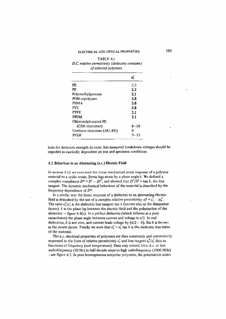
The d.c. relative permittivities of selected polymers are listed in table 4.1.
The values are determined largely by the nature and arrangement of the bonds
in the primary structure. In polymers such as PE, PP and PTFE there is no dipole
in the mer because of symmetry. Furthermore both bonding and non-bonding
electrons are tightly held and displaced little by external fields. These materials
exhibit very little dielectric polarisation, and as a result er is low. Polar polymers
such as PMMA, PVC and notably PVDF possess higher values of er.
The insulating property of any dielectric breaks down in sufficiently strong
electric fields. However, in polymers the dielectric (or electric) strength may be
as high as 1000 MV/m. An upper limit on dielectric strength is set by the
ionisation energies of electrons in covalent bonds within the polymer primary
structure. Purely electrical or intrinsic breakdown occurs when appreciable
numbers of electrons are detached from their parent molecules and accelerate in
the electric field to cause secondary ionisation and avalanching. Breakdown of
this kind runs its course extremely rapidly and the breakdown voltage does not
depend greatly on temperature.
104 POLYMER MATERIALS
(a)
/- :
Vacuum capacitance C0
Dielectric: capacitance e,C0
(b)
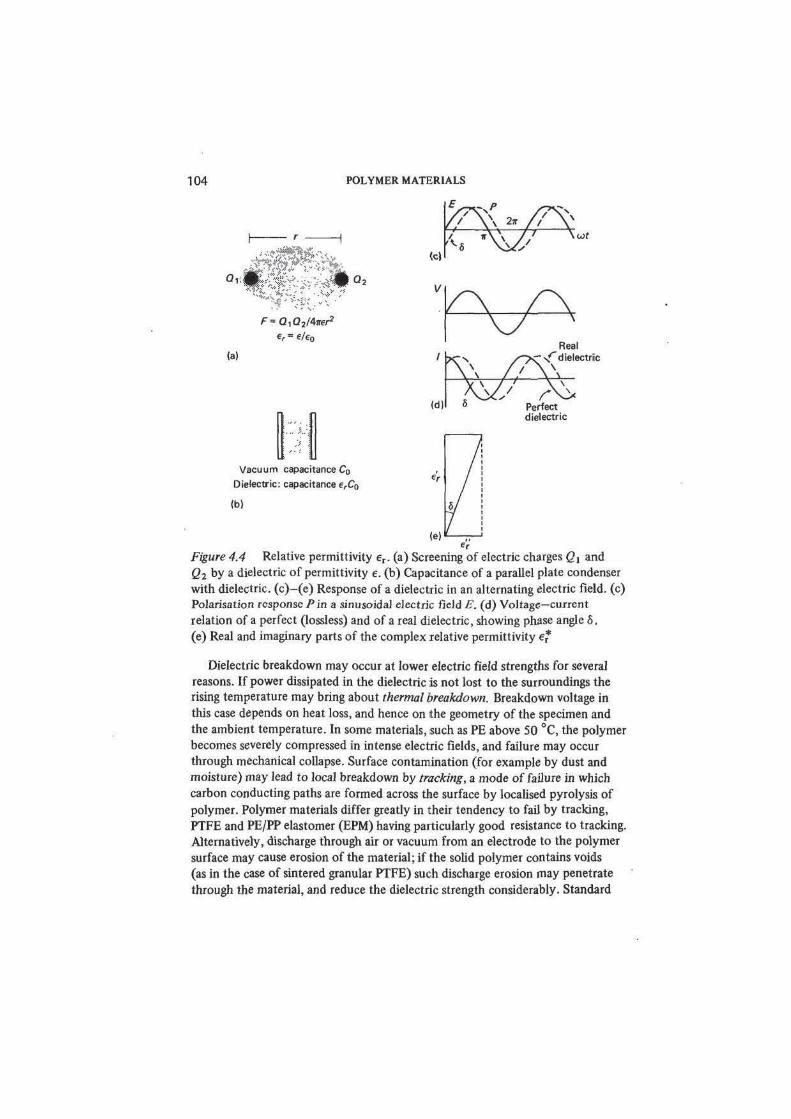
Figure 4.4 Relative permittivity er. (a) Screening of electric charges Qt and
Q2 by a dielectric of permittivity e. (b) Capacitance of a parallel plate condenser
with dielectric, (c)-(e) Response of a dielectric in an alternating electric field, (c)
Polarisation response/*in a sinusoidal electric field B. (d) Voltage—current
relation of a perfect (lossless) and of a real dielectric, showing phase angle 6.
(e) Real and imaginary parts of the complex relative permittivity e*
Dielectric breakdown may occur at lower electric field strengths for several
reasons. If power dissipated in the dielectric is not lost to the surroundings the
rising temperature may bring about thermal breakdown. Breakdown voltage in
this case depends on heat loss, and hence on the geometry of the specimen and
the ambient temperature. In some materials, such as PE above 50 °C, the polymer
becomes severely compressed in intense electric fields, and failure may occur
through mechanical collapse. Surface contamination (for example by dust and
moisture) may lead to local breakdown by tracking, a mode of failure in which
carbon conducting paths are formed across the surface by localised pyrolysis of
polymer. Polymer materials differ greatly in their tendency to fail by tracking,
PTFE and PE/PP elastomer (EPM) having particularly good resistance to tracking.
Alternatively, discharge through air or vacuum from an electrode to the polymer
surface may cause erosion of the material; if the solid polymer contains voids
(as in the case of sintered granular PTFE) such discharge erosion may penetrate
through the material, and reduce the dielectric strength considerably. Standard
, ' / dielectric
b Perfect
dielectric
ELECTRICAL AND OPTICAL PROPERTIES
TABLE 4.1
D.C. relative permittivity (dielectric constant)
of selected polymers
*r
PE 2.3
PP 2.3
Polymethylpentene 2.1
POM copolymer 3.8
PMMA 3.8
PVC 3.8
PTFE 2.1
EPDM 3.1
Chlorosulphonated PE
(CSM elastomer) 8-10
Urethane elastomer (AU, EU) 9
PVDF 9-13
tests for dielectric strength do exist, but measured breakdown voltages should be
regarded as markedly dependent on test and specimen conditions.
4.2 Behaviour in an Alternating (a.c.) Electric Field
In section 3.11 we examined the linear mechanical stress response of a polymer
material to a cyclic strain. Stress lags strain by a phase angle 6. We defined a
complex compliance D* = D' - i£>", and showed that D"/D' = tan 5, the loss
tangent. The dynamic mechanical behaviour of the material is described by the
frequency dependence of D*.
In a similar way the linear response of a dielectric to an alternating electric
field is described by the use of a complex relative permittivity e* = e'T — ie".
The ratio e"/e', is the dielectric loss tangent tan 5 (known also as the dissipation
factor). 8 is the phase lag between the electric field and the polarisation of the
dielectric — figure 4.4(c). In a perfect dielectric (which behaves as a pure
capacitance) the phase angle between current and voltage is jr/2. In real
dielectrics, 6 is not zero, and current leads voltage by (7r/2 — 5). Sin 6 is known
as the power factor. Finally we note that e" = e't tan 6 is the dielectric loss index
of the material.
The a.c. electrical properties of polymers are thus commonly and conveniently
expressed in the form of relative permittivity e'r and loss tangent e"le', data as
functions of frequency (and temperature). Data may extend from d.c. or low
audiofrequency (30 Hz) in half-decade steps to high radiofrequency (1000 MHz)
—see figure 4.5. In pure homogeneous nonpolar polymers, the polarisation arises

150
Temperature
(°C|
100
50
- 50
S s s y, ' / *
* */ y / , V;*
^ x
/ /
/ / #
b,*y
/ ,<$
fcS> / / / #—
— ^ s / / /
#—
— ^
At>
/?P
& / J 'o ? —
4 /
o ? —
#/
< * —
*? /
< * —
*?
//
#
/ /
&/
/
/#
&
/
r
1?
/
°1/s
°1 j—**/
•0/ 1
106
10 102
Frequency (Hz)
103
(a)
10" 10b

tan S
150
Temperature
<°C)
#/j^fe
102 ^ 0 10
3
*»" Frequency (Hz)
(b)
Figure 4.5 Frequency and temperature dependence of (a) permittivity and
(b) loss tangent of PMMA (cast sheet, dry) (Data from ICI Ltd) 107
108 POLYMER MATERIALS
almost entirely from displacements of electrons and nuclei. These redistributions
occur extremely rapidly, in picoseconds or less, and the polarisation response
follows the alternating electric field without lag up to high radiofrequencies and
beyond. As a result polymers of this type, notably PTFE and PE, show little
frequency dependence of e'T and extremely low loss tangents with no loss peaks.
In homogeneous PTFE tan 8 may be as small as 10~5, and since tan 6" * 5 for
small 6 the loss tangent (or loss angle) is often expressed in microradians. The loss
tangents of pure PE and PTFE are so low that they may be sharply increased by
very small concentrations of impurities and additives, or by physical hetero-
geneity. PEs synthesised by different processes may show different loss
characteristics depending on the number of CO impurities incorporated in the
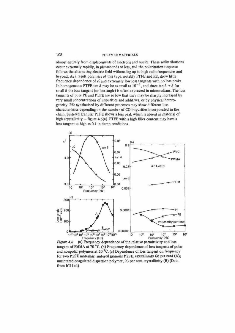
chain. Sintered granular PTFE shows a loss peak which is absent in material of
high crystallinity - figure 4.6(a). PTFE with a high filler content may have a
loss tangent as high as 0.1 in damp conditions.
- 0.08
0.1(b)
0.01 •
tan 5
10 102 10
3 10" 10
5 o.OOl h
Frequency (Hz
300
%S 200 •
i c 100 •
0.0001 •
0.00001
• PA-610
•POM
' lO 2 10 3 10 4 10 5 106107 108109 |10'° 10 102 103 10" 10s 106
Frequency (Hz) Frequency (Hz)
Figure 4.6 (a) Frequency dependence of the relative permittivity and loss
tangent of PMMA at 70 °C. (b) Frequency dependence of loss tangents of polar
and nonpolar polymers at 20 °C. (c) Dependence of loss tangent on frequency
for two PTFE materials: sintered granular PTFE, crystallinity 60 per cent (A);
unsintered coagulated dispersion polymer, 93 per cent crystallinity (B) (Data
from ICI Ltd)
ELECTRICAL AND OPTICAL PROPERTIES 109
The loss tangents of polar polymer materials are generally much higher than
those of nonpolar polymers - figure 4.6(b). As figure 4.6(c) shows, loss peaks
are observed at frequencies corresponding to the relaxation times for dipole
reorientation and the positions of these loss peaks can often be correlated with
known structural transitions, such as Tg and Tm. The permittivity and loss
in the vicinity of a loss peak may be markedly affected by changes in
temperature.
The extremely low dielectric loss of PE and PTFE make these outstanding
materials for high frequency electronic devices and components. The lossy
polymers such as PVC are valuable insulants (for example as cable sheathing) in
low frequency applications. At higher frequencies dielectric heating (and the
possibility at high voltages of thermal breakdown) may become serious in high
loss polymers.
A heated polymer polarised in a very strong electric field and then cooled
may retain its polarisation indefinitely. Such a polarised dielectric is the electro-
static counterpart of a magnet, and is known as an electret. Polymeric electrets
can be prepared with field strengths of 30 kV/cm, showing little loss of strength
over periods of several years. Electrets bearing a net electric charge stable for
long periods can be made from suitable polymer materials carrying metal foil on
one face. Such foil-electrets are used, for example, in microphones.
Finally, we mention the static electrification or triboelectric charging of
polymers by contact or friction. The high resistivity of polymers allows large
electrostatic charges to accumulate. This has many troublesome consequences
(as in textile manufacture and use) and is occasionally hazardous. The study of
how triboelectric charging depends on polymer structure is in its infancy, but
table 4.2 shows a triboelectric series which indicates the sign of the electrostatic
TABLE 4.2
Triboelectric series
Positive end wool
PA
cellulose
cotton
silk
CA
PMMA
PVAL
PETP
PAN
PVC
PVDC
PE
Negative end PTFE
no POLYMER MATERIALS
charge acquired by contact between pairs of dissimilar polymers. Antistatic
formulations of polymers have much reduced resistivities so that electrostatic
charge may be dissipated by leakage currents.
4.3 Optical Properties
The highest a.c. electrical frequencies we have discussed fall within the short
radiowave and microwave regions of the electromagnetic spectrum. The
transmission and absorption of radiation by the polymer dielectric are determined
by the quantities e, and e". Even higher frequencies bring us into the infrared
and visible parts of the spectrum, that is, to optical phenomena. In the rest of
this chapter we discuss the transmission, scattering and absorption of light by
polymer materials.
There is an important underlying continuity in the electrical and optical
behaviour of materials; for example, the optical refractive index n and the high
frequency permittivity are linked in electromagnetic theory by the relation
n = (e[) 2. At optical frequencies as at lower a.c. frequencies absorption of
radiation occurs by irreversible non-radiative loss processes. As we shall see,
absorption of optical radiation occurs by excitation of bond vibrations (infrared)
and rearrangements of electrons within molecules (visible and ultraviolet). Even
so we should not overstress the internal connections between electrical and
optical properties, which in practice are usually considered separately and have
distinct terminologies. In addition we shall see that scattering phenomena play
a major part in determining optical properties. Light scattering is a manifestation
of optical diffraction processes, which occur prominently in polymer materials
having microstructural features of dimensions comparable with optical wavelengths
(0.5 /im). Diffraction effects within materials are rarely important at electrical
a.c. frequencies because of the much greater associated wavelengths.
4.4 Colour and Infrared Absorption
Very few pure polymers absorb radiation in the visible spectrum, that is, roughly
between 380 and 760 nm. Thus most polymers are colourless. The only
exceptions are some thermosets and elastomers, including PF, some
polyurethanes, epoxies and furan resins, which absorb more or less strongly at
the blue end of the spectrum and consequently appear brownish when viewed by
transmitted or reflected light. These substances contain alternating double and
single covalent bonds or aromatic rings which act as chromophores, absorbing
light at frequencies corresponding to the excitation energies of bonding electrons.
Graphite and the other polymeric carbons which have fused ring structures and
which appear intensely black exhibit this absorption throughout the visible
spectrum in extreme form. Deliberately coloured polymer materials are
ELECTRICAL AND OPTICAL PROPERTIES 111
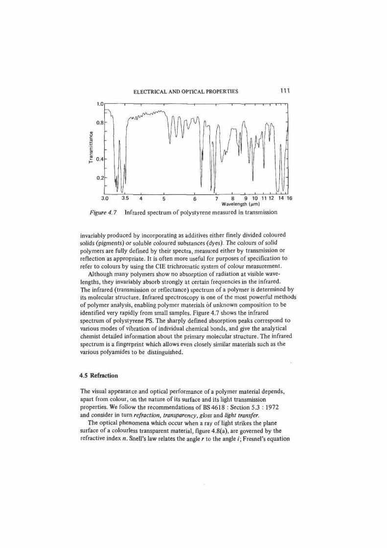
7 8 9 10 11 12 14 16Wavelength (jim)
Figure 4.7 Infrared spectrum of polystyrene measured in transmission
invariably produced by incorporating as additives either finely divided coloured
solids (pigments) or soluble coloured substances (dyes). The colours of solid
polymers are fully defined by their spectra, measured either by transmission or
reflection as appropriate. It is often more useful for purposes of specification to
refer to colours by using the CIE trichromatic system of colour measurement.
Although many polymers show no absorption of radiation at visible wave-
lengths, they invariably absorb strongly at certain frequencies in the infrared.
The infrared (transmission or reflectance) spectrum of a polymer is determined by
its molecular structure. Infrared spectroscopy is one of the most powerful methods
of polymer analysis, enabling polymer materials of unknown composition to be
identified very rapidly from small samples. Figure 4.7 shows the infrared
spectrum of polystyrene PS. The sharply defined absorption peaks correspond to
various modes of vibration of individual chemical bonds, and give the analytical
chemist detailed information about the primary molecular structure. The infrared
spectrum is a fingerprint which allows even closely similar materials such as the
various polyamides to be distinguished.
4.5 Refraction
The visual appearance and optical performance of a polymer material depends,
apart from colour, on the nature of its surface and its light transmission
properties. We follow the recommendations of BS4618 : Section 5.3 : 1972
and consider in turn refraction, transparency, gloss and light transfer.
The optical phenomena which occur when a ray of light strikes the plane
surface of a colourless transparent material, figure 4.8(a), are governed by the
refractive index n. Snell's law relates the angle r to the angle /; Fresnel's equation

112 POLYMER MATERIALS
fli i i 1 . (a| 500 600
, j . Wavelength (ran)
Figure 4.8 (a) Refraction and reflection at the surface of a transparent solid.
(b) Variation with wavelength of the refractive index n of PMMA
allows the intensities and polarisations of the refracted and reflected rays R i and
/?2 to be calculated from n and i. n varies with wavelength and accurate deter-
minations are made with monochromatic light at specified wavelengths, using
selected lines from the atomic emission spectra of elements contained in
discharge lamps. The wavelength dependence of the refractive index, figure
4.8(b), which leads to refractive dispersion of white light is expressed in terms
of the reciprocal dispersive power V& of the material
«(F)-«(C)
where d denotes the helium emission line at 587.6 nm; and F and C denote
hydrogen lines at 486.1 and 656.3 nm.
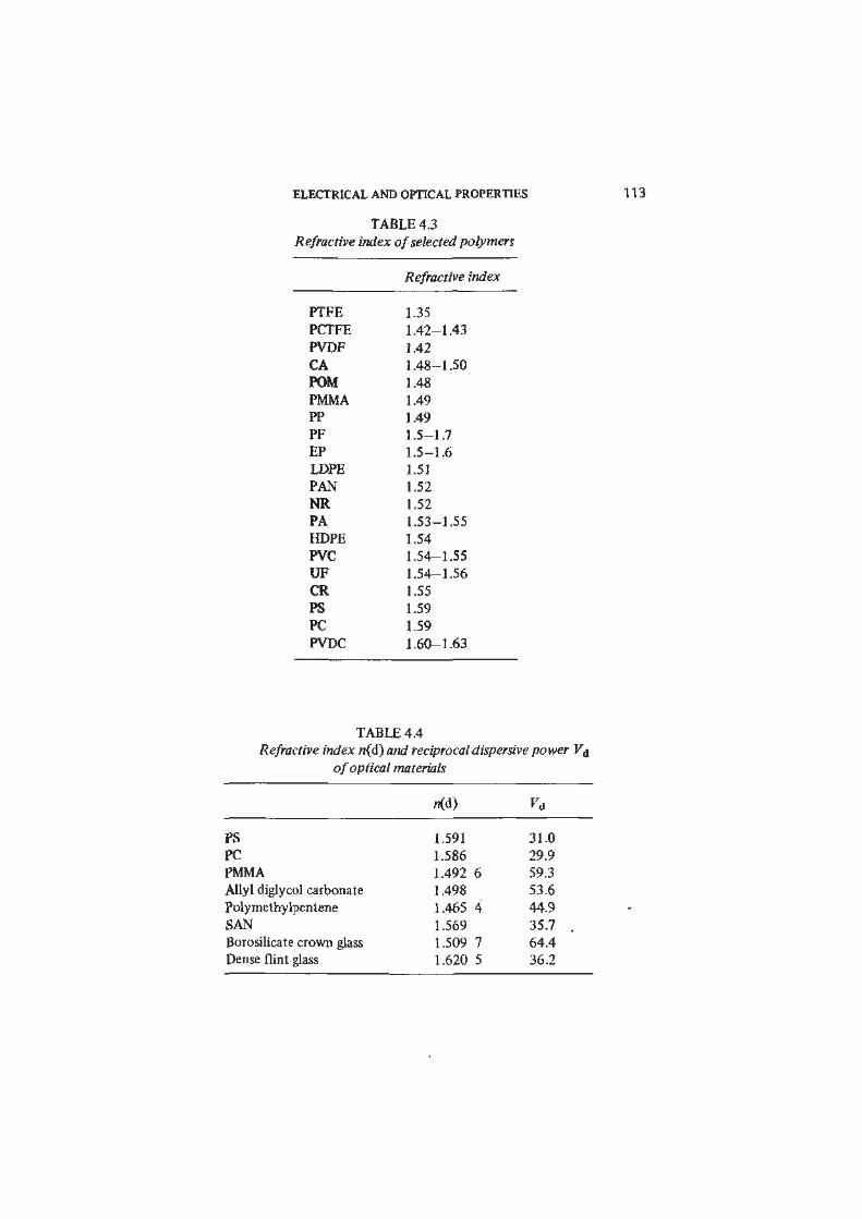
Table 4.3 lists the refractive indices of a number of polymers. More precise
data for polymers which find use as optical materials are given in table 4.4
which includes for comparison two optical glasses.
Refractive index is determined by the extent to which the electronic structure
of the polymer molecules is deformed by the optical frequency electric field of
the radiation. If a material is structurally isotropic, as in the case of unstressed
amorphous polymers, then it is also optically isotropic, and a single refractive
index characterises the refraction behaviour. In crystals and other anisotropic
materials the refractive index takes different values along different principal
axes, and the material is said to be doubly refracting or birefringent. Amorphous
materials under deformation develop birefringence as molecules become aligned.
Similar effects arise in flowing polymer melts. The study of birefringence is thus
a very useful method of exploring the microstructural effects of deformation.
One particularly important technical application of stress-induced birefringence in
ELECTRICAL AND OPTICAL PROPERTIES 113
TABLE 4.3
Refractive index of selected polymers
Refractive index
PTFE 1.35
PCTFE 1.42-1.43
PVDF 1.42
CA 1.48-1.50
POM 1.48
PMMA 1.49
PP 1.49
PF 1.5-1.7
EP 1.5-1.6
LDPE 1.51
PAN 1.52
NR 1.52
PA 1.53-1.55
HDPE 1.54
PVC 1.54-1.55
UF 1.54-1.56
CR 1.55
PS 1.59
PC 1.59
PVDC 1.60-1.63
TABLE 4.4
Refractive index n(d) and reciprocal dispersive power V&
of optical materials
PS
PC
PMMA
Allyl diglycol carbonate
Polymethylpentene
SAN
Borosilicate crown glass
Dense flint glass
1.591 31.0
1.586 29.9
1.492 6 59.3
1.498 53.6
1.465 4 44.9
1.569 35.7
1.509 7 64.4
1.620 5 36.2
114 POLYMER MATERIALS
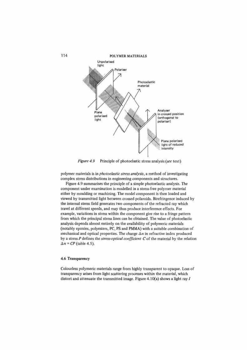
Figure 4.9 Principle of photoelastic stress analysis (see text)
polymer materials is in photoelastic stress analysis, a method of investigating
complex stress distributions in engineering components and structures.
Figure 4.9 summarises the principle of a simple photoelastic analysis. The
component under examination is modelled in a stress-free polymer material
either by moulding or machining. The model component is then loaded and
viewed by transmitted light between crossed polaroids. Birefringence induced by
the internal stress field generates two components of the refracted ray which
travel at different speeds, and may thus produce interference effects. For
example, variations in stress within the component give rise to a fringe pattern
from which the principal stress lines can be obtained. The value of photoelastic
analysis depends almost entirely on the availability of polymeric materials
(notably epoxies, polyesters, PC, PS and PMMA) with a suitable combination of
mechanical and optical properties. The change AM in refractive index produced
by a stress P defines the stress-optical coefficient C of the material by the relation
An = CP (table 4.5).
4.6 Transparency
Colourless polymeric materials range from highly transparent to opaque. Loss of
transparency arises from light scattering processes within the material, which
distort and attenuate the transmitted image. Figure 4.10(a) shows a light ray /
ELECTRICAL AND OPTICAL PROPERTIES 115
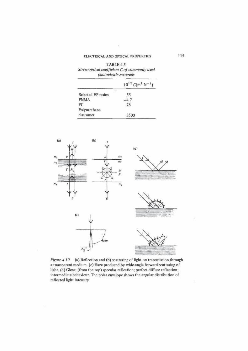
TABLE 4.5
Stress-optical coefficient C of commonly used
photoelastic materials
1 0 l 2 C ( m 2 N - 1 )
Selected EP resins 55
PMMA -4.7
PC 78
Polyurethane
elastomer 3500
Id)
Haze
Figure 4.10 (a) Reflection and (b) scattering of light on transmission through
a transparent medium, (c) Haze produced by wide-angle forward scattering of
light, (d) Gloss: (from the top) specular reflection; perfect diffuse reflection;
intermediate behaviour. The polar envelope shows the angular distribution of
reflected light intensity

116 POLYMER MATERIALS
striking a plane surface at right angles. A small fraction of the incident flux is
reflected back from the surface at the point of incidence p. The ratio of reflected
to transmitted flux is calculated by Fresnel's equation and for normal incidence
<p(Ri)l(t>(T) = (n2 -n i ) 2 /4«]«2- At an air-polymer interface, with n2 = 1.5,
about 4 per cent of the incident flux is reflected. If the air is replaced by a
transparent liquid having the same refractive index as the polymer the surface
reflection at p (and also at r) is eliminated — figure 4.10(b).
If the material is non-absorbing and optically homogeneous and isotropic the
transmitted ray propagates without loss of intensity. In real materials the trans-
mitted ray may lose some intensity as it travels forward as the result of scattering
from refractive index inhomogeneities within the material figure 4.10(b). Such
scattering is akin to the ray splitting which occurs at the surface at p and which
is repeated whenever the ray encounters a change of refractive index 8n2 at
points q within the material. The angular distribution of the scattered light is
unlikely to be simple, but it is useful to speak of back-scattered and forward-
scattered components B and F of the total flux. In figure 4.10(b) we have
<p(I) = (t>(B) + <t>(F) + <p (£), where E is the undeviated emergent ray. The direct
transmission factor T of the material is determined as the ratio <l>(E)/<p(I). For
weakly scattering colourless materials T decreases exponentially with the sample
thickness /, and therefore In T = — ol, where a is the scattering coefficient.
The effect of scattering is to reduce the cpntrast between light and dark
parts of the object viewed through the transparent polymer, and thus to produce
haze or milkiness in the transmitted image. The direct transmission factor, the
total transmitted flux <pT, i.e. the sum of <p(F) and 4>(E), and the forward-
scattered fraction <t>(F)l<t>T can be determined photometrically.
Besides haze, scattering may produce loss of clarity so that distinct features
of the object can no longer be distinguished in the transmitted image. Loss of
clarity is caused by forward scattering at angles very close to the undeviated
beam, since it arises from confusion of light rays diverging from the object at
the limits of the angular resolution of the eye. Haze on the other hand is
associated with scattering over a wide range of angles. A quantitative measure
of haze is obtained in an ASTM standard test from the total forward-scattered
flux, excluding that within 2M degrees of the undeviated ray - see figure 4.10(c).
In polymer materials heterogeneity of refractive index can arise from
differences of density in amorphous and crystalline regions within the polymer
itself, or from solid particles incorporated as pigments or fillers, or from voids.
The degree of scattering depends strongly on the variation of refractive index
(± 5«2) and on the size of the heterogeneities. The most efficient scattering
occurs when the scattering centres are comparable in dimensions with the
wavelength of light. The scattering of light in pigmented polymer films has been
extensively studied in connection with the optical properties of paints (see
section 6.8). Crystalline polymers are normally translucent or opaque unless it
happens (as in polymethylpentene) that there is little difference in the refractive
indices of crystalline and amorphous regions or (as in cellulose triacetate) that
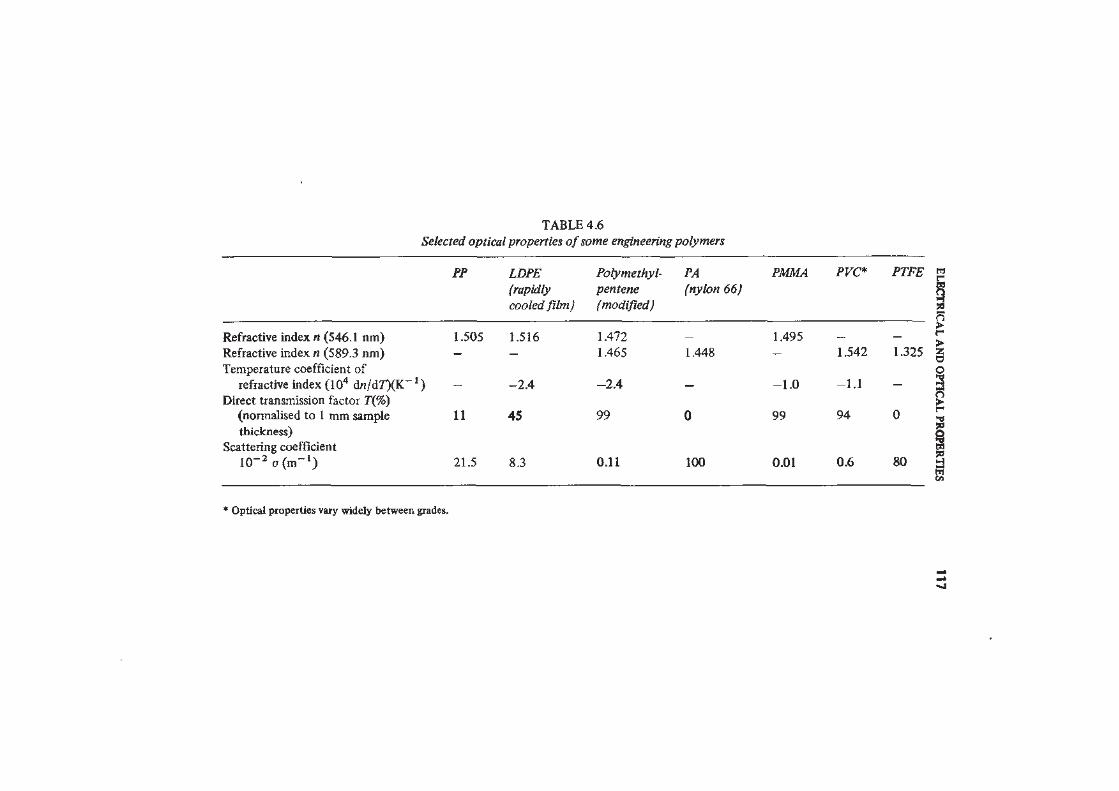
TABLE 4.6
Selected optical properties of some engineering polymers
PP LDPE Polymethyl- PA
(rapidly pentene (nylon 66)
cooled film) (modified)
Refractive index n (546.1 nm) 1.505 1.516 1.472 _
Refractive index n (589.3 nm) — — 1.465 1.448
Temperature coefficient of
refractive index (104 dn/dr)fK~') — -2.4 -2.4 -
Direct transmission factor 7\%)
(normalised to 1 mm sample 11 45 99 0
thickness)Scattering coefficient
lO^aOn"1) 21.5 8.3 0.11 100
PMMA PVC* PTFE E
50
n>
1.495
1.542 1.325
-1.0 -1.1
99 94 0
0.01 0.6 80
>zao
>r
50
I* Optical properties va*y widely between grades.
- J
118 POLYMER MATERIALS
the spherulites are exceptionally small. It is frequently possible to enhance the
transparency of polymer materials by assisted nucleation or by rapid cooling
from the melt, both means of decreasing the spherulite size. Stretching is also
an effective way of increasing transparency, since spherulites are transformed
into oriented fibrils which scatter light less effectively.
4.7 Gloss
'Gloss' is a term applied to the surface optical character of a material, whether
transparent or opaque. A perfect mirror-like surface, a specular reflector, shows
one extreme of behaviour — figure 4.10(d). At the other extreme, a highly
scattering surface (a perfect diffuse reflector) reflects light equally in all
directions at all angles of incidence.
The gloss of real surfaces is most completely described by the angular intensity
distribution of reflected light for one or more angles of incidence. A somewhat
simpler index of surface appearance is the direct reflection factor, the ratio of
the flux reflected at the specular angle to the incident flux, for angles of
incidence from 0 to 90 degrees.
Table 4.6 collates optical data on a number of engineering polymers.
4.8 Light Transfer
Strongly scattering translucent materials (optical 'diffusers') are unable to
transmit useful images but nevertheless may transmit appreciable amounts of
diffuse light. Their optical characteristics are most simply expressed through the
total transmission factor 7" (or luminous transmittance) for normal incidence,
which is defined as [4>(F) + 4>(E)] /0(/).
Suggestions for Reading
Electrical Properties
ASTM D149-81, Dielectric breakdown voltage and dielectric strength of solid
electrical insulating materials at commercial power frequencies (American
Society for Testing and Materials, Philadelphia, Pa.).
ASTM D150-81, A-C loss characteristics and permittivity (dielectric constant)
of solid electrical insulating materials (American Society for Testing and
Materials, Philadelphia, Pa.).
ASTM D257-78, D-C resistance or conductance of insulating materials
(American Society for Testing and Materials, Philadelphia, Pa.).
ELECTRICAL AND OPTICAL PROPERTIES 119
Baird, M. E., Electrical Properties of Polymeric Materials (The Plastics Institute,
London, 1973).
Block, H., The nature and application of electrical phenomena in polymers',
AppL Polymer Set, 33 (1979) 93-167.
Blythe, A. R., Electrical Properties of Polymers (Cambridge University Press,
1979).
Brown, R. P. (Ed.), 'Electrical properties', in Handbook of Plastics Test Methods,
2nd edn (Godwin, London, 1981).
BS 4618: Part 2: 1970, Electrical properties.
Buckingham, K. A., 'Electrical properties', in R. M. Ogorkiewicz (Ed.),
Thermoplastics: Properties and Design, ch 7 (Wiley, London, 1974).
Goosey, M. T. (Ed.), Plastics for Electronics (Applied Science, London, 1985).
Harper, C. A., 'Electrical applications', in Encyclopaedia of Polymer Science and
Technology, vol. 5, pp. 482-528 (Wiley, New York, 1966).
Harrop, P., Dielectrics (Butterworths, London, 1972).
Ku, C. C. and Liepins, R., Electrical Properties of Polymers (Hanser, Munich,
1987).
Mathes, K. N., 'Electrical properties', in Encyclopaedia of Polymer Science and
Engineering, 2nd edn, vol. 5, pp. 507-587 (Wiley, New York, 1986).
Norman, R. H., Conductive Rubbers and Plastics (Elsevier, Amsterdam, 1970):
O'Dwyer, J. J., The Theory of Electrical Conduction and Breakdown in Solid
Dielectrics (Oxford University Press, 1973).
Seanor, Donald A., 'Electrical properties of polymers', in A. D. Jenkins (Ed.),
Polymer Science, vol. 2, ch. 17 (North-Holland, Amsterdam, 1972).
Seanor, D. A. (Ed.), Electrical Properties of Polymers (Academic Press, New
York, 1982).
Sillars, R. W., Electrical Insulating Materials and their Application, IEE
Monograph Series 14 (Peter Peregrinus, Stevenage, for The Institution of
Electrical Engineers, 1973).
Solymar, L. and Walsh, D., Lectures on the Electrical Properties of Materials,
4th edn (Oxford University Press, 1988).
Williams, M. W., 'Dependence of triboelectric charging of polymers on their
chemical compositions',Rev. Macromol. Chem., I4B(1976) 251-265.
Wintle, H. J., 'Theory of electrical conductivity of polymers', in M. Dole (Ed.),
The Radiation Chemistry ofMacromolecules, vol. l .pp. 109-126 (Academic
Press, New York, 1972).
Optical Properties
ASTM D523-85, Specular gloss (American Society for Testing and Materials,
Philadelphia, Pa.).
ASTM D1003-61, Haze and luminous transmittance of transparent plastics
(American Society for Testing and Materials, Philadelphia, Pa.).

120 POLYMER MATERIALS
Brown, R. P. (Ed.), 'Optical properties', in Handbook of Plastics Test Methods,
2nd edn (Godwin, London, for the Plastics Institute, 1981).
BS 4618: Section 5.3 : 1972, Recommendations for the presentation of plastics
design data: optical properties.
Hunter, R. S. and Boor, L., 'Tests for surface appearance of plastics', in John
V. Schmitz (Ed.), Testing of Polymers, vol. 2 (Interscience, New York, 1966).
Kuske, A. and Robertson, G., Photoelastic Stress Analysis (Wiley-Interscience,
New York, 1974).
Meeten, G. H. (Ed.), Optical Properties of Polymers (Elsevier Applied Science,
London, 1986).
Meinecke, E., 'Optical properties: survey' in Encyclopaedia ofPolymer Science
and Technology, vol. 9, pp. 525-551 (Wiley, New York, 1968).
Redner, S., 'Optical properties: photoelasticity', in Encyclopaedia of Polymer
Science and Technology, vol. 9, pp. 590-610 (Wiley, New York, 1968).
Ross, G. and Birley, A. W., 'Optical properties of polymeric materials and their
measurement',/. Phys. D.: Appl. Phys., 6 (1973) 795-808.
Ross, G. and Birley, A. W., 'Optica! properties', in R. M. Ogorkiewicz (Ed.),
Thermoplastics: Properties and Design (Wiley, London, 1974).
Wright, W. D., Measurement of Colour, 3rd edn (Hilger & Watts, London, 1964).
Related Documents