9.1 INTRODUCTION The Cathode Ray Oscilloscope (CRO) is a very useful and versatile laboratory instrument used for display, measurement and analysis of waveform and other phenomena in electrical and electronic circuits. CROs are, in fact, very fast X-Y plotters, displaying an input signal versus another signal or versus time. The ‘stylus’ of this ‘plotter’ is a luminous spot which moves over the display area in response to an input voltage. The luminous spot is produced by a beam of electrons striking a fluorescent screen. The extremely low inertia effects associated with a beam of electrons enables such a beam to be used following the changes in instantaneous values of rapidly varying voltages. The normal form of a CRO uses a horizontal input voltage which is an internally generated ramp voltage called ‘time base’. The horizontal voltage moves the luminous spot periodically in a horizontal direction from left to right over the display area or screen. The vertical input to the CRO is the voltage under investigation. The vertical input voltage moves the luminous spot up and down in accordance with the instantaneous value of the voltage. The luminous spot thus traces the waveform of the input voltage with respect to time. When the input voltage repeats itself at a fast rate, the display on the screen appears stationary on the screen. The CRO thus provides a means of visualising time-varying voltages. As such, the CRO has become a universal tool in all kinds of electrical and electronic investigation. 9.2 BLOCK DIAGRAM OF A CATHODE RAY TUBE (CRT) The main part of the CRO is Cathode Ray Tube (CRT). It generates the electron beam, accelerates the beam to a high velocity, deflects the beam to create the image and contains a phosphor screen where the electron beam eventually becomes visible. The phosphor screen is coated with ‘aquadag’ to collect the secondary emitted electrons. For accomplishing these tasks, various electrical signals and voltages are required, which are provided by the power supply circuit of the oscilloscope. Low voltage supply is required for the heater of the electron gun for generation of electron beam and high voltage, of the order of few thousand volts, is required for cathode ray tube to accelerate the beam. Normal voltage supply, say a few hundred volts, is required for other control circuits of the oscilloscope. Horizontal and vertical deflecting plates are fitted between the electron gun and screen to deflect the beam according to the input signal. The electron beam strikes the screen and creates a visible spot. This spot is deflected on the screen in the horizontal direction (X- www.EngineeringBooksLibrary.com

Welcome message from author
This document is posted to help you gain knowledge. Please leave a comment to let me know what you think about it! Share it to your friends and learn new things together.
Transcript
9.1 INTRODUCTION
TheCathodeRayOscilloscope(CRO)isaveryusefulandversatilelaboratoryinstrumentused for display, measurement and analysis of waveform and other phenomena inelectricalandelectroniccircuits.CROsare, in fact,veryfastX-Y plotters,displayinganinput signal versus another signal or versus time. The ‘stylus’ of this ‘plotter’ is aluminous spotwhichmoves over the display area in response to an input voltage. Theluminous spot is produced by a beam of electrons striking a fluorescent screen. Theextremelylowinertiaeffectsassociatedwithabeamofelectronsenablessuchabeamtobeusedfollowingthechangesininstantaneousvaluesofrapidlyvaryingvoltages.
The normal form of a CRO uses a horizontal input voltage which is an internallygenerated ramp voltage called ‘time base’. The horizontal voltagemoves the luminousspotperiodicallyinahorizontaldirectionfromlefttorightoverthedisplayareaorscreen.TheverticalinputtotheCROisthevoltageunderinvestigation.Theverticalinputvoltagemovestheluminousspotupanddowninaccordancewiththeinstantaneousvalueofthevoltage.Theluminousspotthustracesthewaveformoftheinputvoltagewithrespecttotime.Whentheinputvoltagerepeatsitselfatafastrate,thedisplayonthescreenappearsstationary on the screen. The CRO thus provides a means of visualising time-varyingvoltages. As such, the CRO has become a universal tool in all kinds of electrical andelectronicinvestigation.
9.2 BLOCKDIAGRAMOFACATHODERAYTUBE(CRT)
Themainpartof theCRO isCathodeRayTube (CRT). Itgenerates theelectronbeam,acceleratesthebeamtoahighvelocity,deflectsthebeamtocreatetheimageandcontainsa phosphor screen where the electron beam eventually becomes visible. The phosphorscreen is coated with ‘aquadag’ to collect the secondary emitted electrons. Foraccomplishingthesetasks,variouselectricalsignalsandvoltagesarerequired,whichareprovidedbythepowersupplycircuitoftheoscilloscope.Lowvoltagesupplyisrequiredfortheheateroftheelectrongunforgenerationofelectronbeamandhighvoltage,oftheorder of few thousand volts, is required for cathode ray tube to accelerate the beam.Normalvoltagesupply,saya fewhundredvolts, is requiredforothercontrolcircuitsoftheoscilloscope.
Horizontalandverticaldeflectingplatesarefittedbetweentheelectrongunandscreentodeflectthebeamaccordingtotheinputsignal.Theelectronbeamstrikesthescreenandcreatesavisiblespot.Thisspot isdeflectedonthescreeninthehorizontaldirection(X-
www.EngineeringBooksLibrary.com
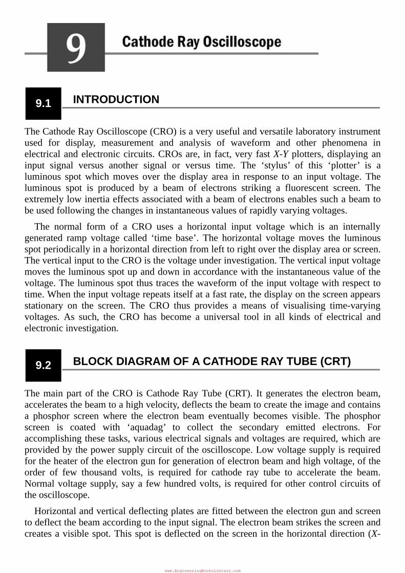
axis) with constant time dependent rate. This is accomplished by a time base circuitprovidedintheoscilloscope.Thesignaltobeviewedissuppliedtotheverticaldeflectionplates through the vertical amplifier, which raises the potential of the input signal to alevelthatwillprovideusabledeflectionoftheelectronbeam.Nowelectronbeamdeflectsin two directions, horizontal on X-axis and vertical on Y-axis. A triggering circuit isprovidedforsynchronisingtwotypesofdeflectionssothathorizontaldeflectionstartsatthesamepointoftheinputverticalsignaleachtimeitsweeps.Abasicblockdiagramofageneral-purposeoscilloscopeisshowninFigure9.1(a)andaschematicofinternalpartsofaCRTisshowninFigure9.1(b).
Figure9.1(a)Blockdiagramofageneral-purposeCRO
Figure9.1(b)CathodeRayTube(CRT)
9.3 ELECTROSTATICDEFLECTION
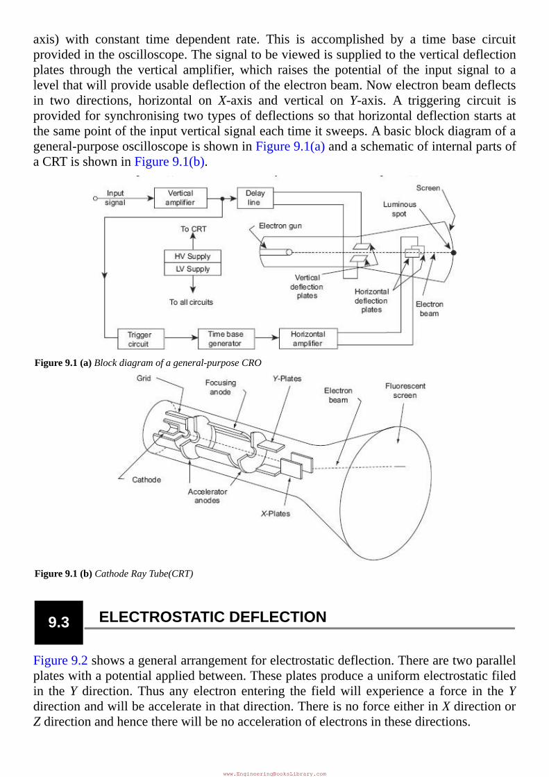
Figure9.2showsageneralarrangementforelectrostaticdeflection.Therearetwoparallelplateswithapotentialappliedbetween.Theseplatesproduceauniformelectrostaticfiledin theY direction.Thus any electron entering the fieldwill experience a force in theYdirectionandwillbeaccelerateinthatdirection.ThereisnoforceeitherinXdirectionorZdirectionandhencetherewillbenoaccelerationofelectronsinthesedirections.
www.EngineeringBooksLibrary.com
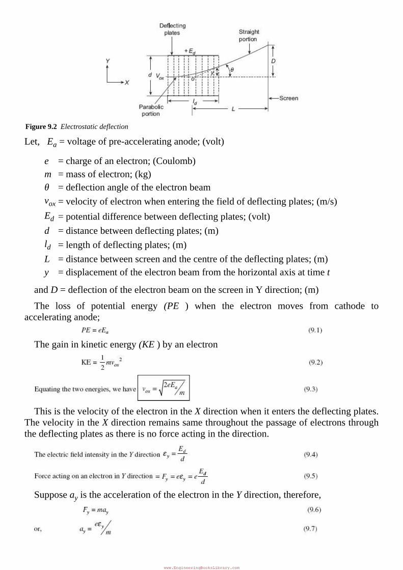
Figure9.2Electrostaticdeflection
Let,Ea=voltageofpre-acceleratinganode;(volt)
e = chargeofanelectron;(Coulomb)m = massofelectron;(kg)θ = deflectionangleoftheelectronbeamvox = velocityofelectronwhenenteringthefieldofdeflectingplates;(m/s)Ed = potentialdifferencebetweendeflectingplates;(volt)d = distancebetweendeflectingplates;(m)ld = lengthofdeflectingplates;(m)L = distancebetweenscreenandthecentreofthedeflectingplates;(m)y = displacementoftheelectronbeamfromthehorizontalaxisattimet
andD=deflectionoftheelectronbeamonthescreeninYdirection;(m)
The loss of potential energy (PE ) when the electron moves from cathode toacceleratinganode;
Thegaininkineticenergy(KE)byanelectron
ThisisthevelocityoftheelectronintheXdirectionwhenitentersthedeflectingplates.ThevelocityintheXdirectionremainssamethroughoutthepassageofelectronsthroughthedeflectingplatesasthereisnoforceactinginthedirection.
SupposeayistheaccelerationoftheelectronintheYdirection,therefore,
www.EngineeringBooksLibrary.com
Asthere isno initialvelocity in theYdirection[Eq. (9.8)], thedisplacementyatanyinstanttintheYdirectionis
AsthevelocityintheXdirectionisconstant,thedisplacementinXdirectionisgivenby
SubstitutingtheabovevalueoftinEq.(9.8),wehave
Thisistheequationofaparabola.
Puttingx=ldinEq.(9.12),wegetthevalueoftanθ.
After leaving thedeflectionplates, the electrons travel in a straight line.The straightlineoftravelofelectronistangenttotheparabolaatx=ldandthistangentintersectstheXaxisatpointO’.Thelocationofthispointisgivenby
Theapparentorigin is thus thecentreof thedeflectingplates, thedeflectionDon thescreenisgivenby
FromEq.(9.16)weconcludethefollowing:
For a given accelerating voltage Ea, and for particular dimensions of CRT, thedeflection of the electron beam is directly proportional to the deflecting voltage. ThismeansthattheCRTmaybeusedasalinearindicatingdevice.
ThediscussionsaboveassumethatEd isa fixeddcvoltage.Thedeflectionvoltage isusuallyatimevaryingquantityandtheimageonthescreenthusfollowsthevariationofthedeflectionsvoltageinalinearmanner.
Thedeflectionisindependentofthe(e/m)ratio.Inacathoderaytube,inadditiontotheelectronsmany typesof negative ions such as oxygen, carbon, chlorine etc arepresent.With electrostatic deflection system, because deflection is independent of e/m, the ions
www.EngineeringBooksLibrary.com
travelwith the electrons and are not concentrated at onepoint.Hence cathode ray tubewithelectrostaticdeflectionsystemdoesnotproduceanionburn.
Thedeflectionsensitivity of aCRT is defined as thedeflectionof the screenper unitdeflectionvoltage.
ThedeflectionfactorofaCRTisdefinedasthereciprocalofsensitivity
ItisclearfromEq.(9.17),thatthesensitivitycanbeincreasedbydecreasingthevalueof accelerating voltageEa. but this has a disadvantage as the luminosity of the spot isdecreasedwithdecreaseinEa.On theotherhandahighvalueofEa,producedahighlyacceleratedbeamand thusproducesabright spot.However, ahighacceleratingvoltage(Ea) requires a high deflection potential (Ed) for a given deflection. Also, highlyacceleratedbeamismoredifficulttodeflectandissometimescalledhardbeam.
Example9.1 AnelectricallydeflectedCRThasa finalanodevoltageof2000Vandparalleldeflectingplates1.5cmlongand5mmapart. If the screen is 50 cm from the centre of deflectingplates,find(a)beamspeed,(b)thedeflectionsensitivityofthetube,and(c)thedeflectionfactorofthetube.
SolutionVelocityofthebeam
Deflectionsensitivity,
Example9.2 CalculatethemaximumvelocityofthebeamofelectronsinaCRT having a anode voltage of 800V.Assume that theelectrons to leave the anodewith zero velocity.Charge ofelectron = 1.6 × 10⁻¹⁹ C and mass of electron = 9.1 ×10⁻³¹kg.
SolutionVelocityofelectronis
www.EngineeringBooksLibrary.com
Example9.3 ACRThasananodevoltageof2000Vand2cmlongand5mm apart parallel deflecting plates. The screen is 30 cmfromthecentreoftheplates.Findtheinputvoltagerequiredto deflect the beam through 3 cm. The input voltage isapplied to the deflecting plates through amplifiers havinganoverallgainof100.
Solution
9.4 TIMEBASEGENERATOR
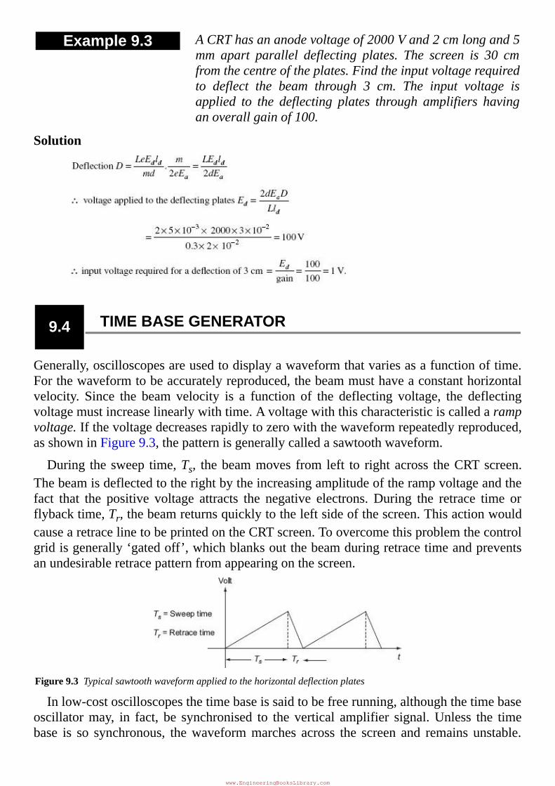
Generally,oscilloscopesareusedtodisplayawaveformthatvariesasafunctionoftime.Forthewaveformtobeaccuratelyreproduced,thebeammusthaveaconstanthorizontalvelocity. Since the beam velocity is a function of the deflecting voltage, the deflectingvoltagemustincreaselinearlywithtime.Avoltagewiththischaracteristiciscalledarampvoltage.Ifthevoltagedecreasesrapidlytozerowiththewaveformrepeatedlyreproduced,asshowninFigure9.3,thepatternisgenerallycalledasawtoothwaveform.
During thesweep time,Ts, thebeammoves from left to rightacross theCRTscreen.Thebeamisdeflectedtotherightbytheincreasingamplitudeoftherampvoltageandthefact that the positive voltage attracts the negative electrons. During the retrace time orflybacktime,Tr,thebeamreturnsquicklytotheleftsideofthescreen.ThisactionwouldcausearetracelinetobeprintedontheCRTscreen.Toovercomethisproblemthecontrolgridisgenerally‘gatedoff’,whichblanksoutthebeamduringretracetimeandpreventsanundesirableretracepatternfromappearingonthescreen.
Figure9.3Typicalsawtoothwaveformappliedtothehorizontaldeflectionplates
Inlow-costoscilloscopesthetimebaseissaidtobefreerunning,althoughthetimebaseoscillatormay, in fact, be synchronised to the vertical amplifier signal.Unless the timebase is so synchronous, thewaveformmarches across the screen and remains unstable.
www.EngineeringBooksLibrary.com
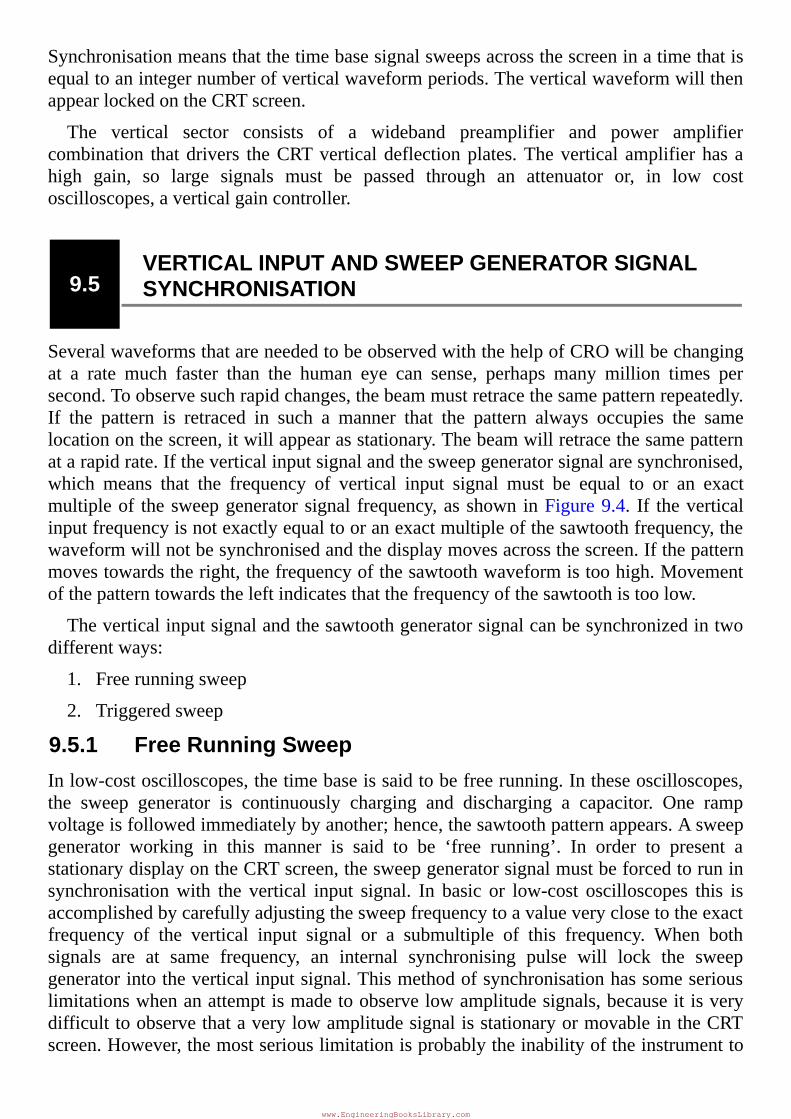
Synchronisationmeansthatthetimebasesignalsweepsacrossthescreeninatimethatisequaltoanintegernumberofverticalwaveformperiods.TheverticalwaveformwillthenappearlockedontheCRTscreen.
The vertical sector consists of a wideband preamplifier and power amplifiercombination thatdrivers theCRTverticaldeflectionplates.Thevertical amplifierhas ahigh gain, so large signals must be passed through an attenuator or, in low costoscilloscopes,averticalgaincontroller.
9.5VERTICALINPUTANDSWEEPGENERATORSIGNALSYNCHRONISATION
SeveralwaveformsthatareneededtobeobservedwiththehelpofCROwillbechangingat a rate much faster than the human eye can sense, perhaps many million times persecond.Toobservesuchrapidchanges,thebeammustretracethesamepatternrepeatedly.If the pattern is retraced in such a manner that the pattern always occupies the samelocationonthescreen,itwillappearasstationary.Thebeamwillretracethesamepatternatarapidrate.Iftheverticalinputsignalandthesweepgeneratorsignalaresynchronised,which means that the frequency of vertical input signal must be equal to or an exactmultipleof thesweepgeneratorsignal frequency,asshowninFigure9.4. If theverticalinputfrequencyisnotexactlyequaltooranexactmultipleofthesawtoothfrequency,thewaveformwillnotbesynchronisedandthedisplaymovesacrossthescreen.Ifthepatternmovestowardstheright,thefrequencyofthesawtoothwaveformistoohigh.Movementofthepatterntowardstheleftindicatesthatthefrequencyofthesawtoothistoolow.
Theverticalinputsignalandthesawtoothgeneratorsignalcanbesynchronizedintwodifferentways:
1.Freerunningsweep
2.Triggeredsweep
9.5.1FreeRunningSweepInlow-costoscilloscopes,thetimebaseissaidtobefreerunning.Intheseoscilloscopes,the sweep generator is continuously charging and discharging a capacitor. One rampvoltageisfollowedimmediatelybyanother;hence,thesawtoothpatternappears.Asweepgenerator working in this manner is said to be ‘free running’. In order to present astationarydisplayontheCRTscreen,thesweepgeneratorsignalmustbeforcedtoruninsynchronisationwith the vertical input signal. In basic or low-cost oscilloscopes this isaccomplishedbycarefullyadjustingthesweepfrequencytoavalueveryclosetotheexactfrequency of the vertical input signal or a submultiple of this frequency. When bothsignals are at same frequency, an internal synchronising pulse will lock the sweepgeneratorintotheverticalinputsignal.Thismethodofsynchronisationhassomeseriouslimitationswhenanattemptismadetoobservelowamplitudesignals,becauseitisverydifficulttoobservethataverylowamplitudesignalisstationaryormovableintheCRTscreen.However,themostseriouslimitationisprobablytheinabilityoftheinstrumentto
www.EngineeringBooksLibrary.com
maintain synchronisationwhen the amplitude or frequency of the vertical signal is notconstant,suchasvariablefrequencyaudiosignalorvoice.
Figure9.4SynchronisedwaveformsandCRTdisplay
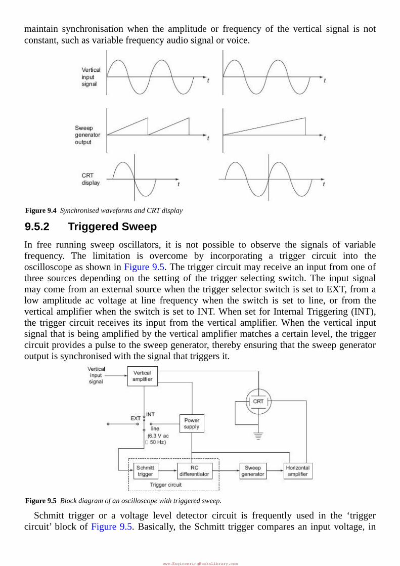
9.5.2TriggeredSweepIn free running sweep oscillators, it is not possible to observe the signals of variablefrequency. The limitation is overcome by incorporating a trigger circuit into theoscilloscopeasshowninFigure9.5.Thetriggercircuitmayreceiveaninputfromoneofthree sources depending on the setting of the trigger selecting switch. The input signalmaycomefromanexternalsourcewhenthetriggerselectorswitchissettoEXT,fromalow amplitude ac voltage at line frequencywhen the switch is set to line, or from theverticalamplifierwhentheswitchisset toINT.WhensetforInternalTriggering(INT),the trigger circuit receives its input from the vertical amplifier.When the vertical inputsignalthatisbeingamplifiedbytheverticalamplifiermatchesacertainlevel,thetriggercircuitprovidesapulsetothesweepgenerator,therebyensuringthatthesweepgeneratoroutputissynchronisedwiththesignalthattriggersit.
Figure9.5Blockdiagramofanoscilloscopewithtriggeredsweep.
Schmitt trigger or a voltage level detector circuit is frequently used in the ‘triggercircuit’blockofFigure9.5.Basically, theSchmitt triggercomparesan inputvoltage, in
www.EngineeringBooksLibrary.com
thiscasefromtheverticalamplifier,withapre-setvoltage.
9.6MEASUREMENTOFELECTRICALQUANTITIESWITHCRO
TheCROisaveryversatileinstrumentinlaboratoryformeasurementofvoltage,current,frequency and phase angle of any electrical quantity. But beforewe go aheadwith thediscussion on measurement of electrical quantities with a CRO, we should understandsomebasicoscilloscopepatterns.
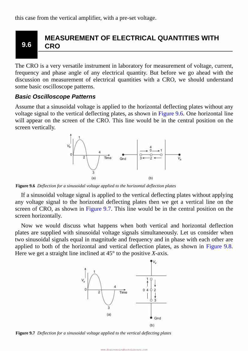
BasicOscilloscopePatternsAssumethatasinusoidalvoltageisappliedtothehorizontaldeflectingplateswithoutanyvoltagesignaltotheverticaldeflectingplates,asshowninFigure9.6.Onehorizontallinewillappearon the screenof theCRO.This linewouldbe in thecentralpositionon thescreenvertically.
Figure9.6Deflectionforasinusoidalvoltageappliedtothehorizontaldeflectionplates
Ifasinusoidalvoltagesignalisappliedtotheverticaldeflectingplateswithoutapplyingany voltage signal to the horizontal deflecting plates thenwe get a vertical line on thescreenofCRO,asshowninFigure9.7.Thislinewouldbeinthecentralpositiononthescreenhorizontally.
Now we would discuss what happens when both vertical and horizontal deflectionplatesaresuppliedwithsinusoidalvoltagesignalssimultaneously.Letusconsiderwhentwosinusoidalsignalsequalinmagnitudeandfrequencyandinphasewitheachotherareapplied to both of the horizontal and vertical deflection plates, as shown in Figure9.8.Herewegetastraightlineinclinedat45°tothepositiveX-axis.
Figure9.7Deflectionforasinusoidalvoltageappliedtotheverticaldeflectingplates
www.EngineeringBooksLibrary.com
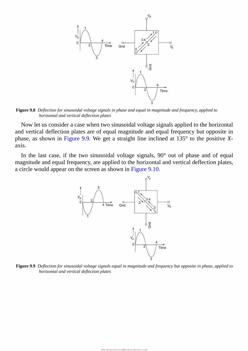
Figure9.8Deflectionforsinusoidalvoltagesignalsinphaseandequalinmagnitudeandfrequency,appliedtohorizontalandverticaldeflectionplates
Nowletusconsideracasewhentwosinusoidalvoltagesignalsappliedtothehorizontalandverticaldeflectionplatesareofequalmagnitudeandequalfrequencybutoppositeinphase,asshowninFigure9.9.Wegeta straight line inclinedat135° to thepositiveX-axis.
In the last case, if the two sinusoidal voltage signals, 90° out of phase and of equalmagnitudeandequalfrequency,areappliedtothehorizontalandverticaldeflectionplates,acirclewouldappearonthescreenasshowninFigure9.10.
Figure9.9Deflectionforsinusoidalvoltagesignalsequalinmagnitudeandfrequencybutoppositeinphase,appliedtohorizontalandverticaldeflectionplates
www.EngineeringBooksLibrary.com
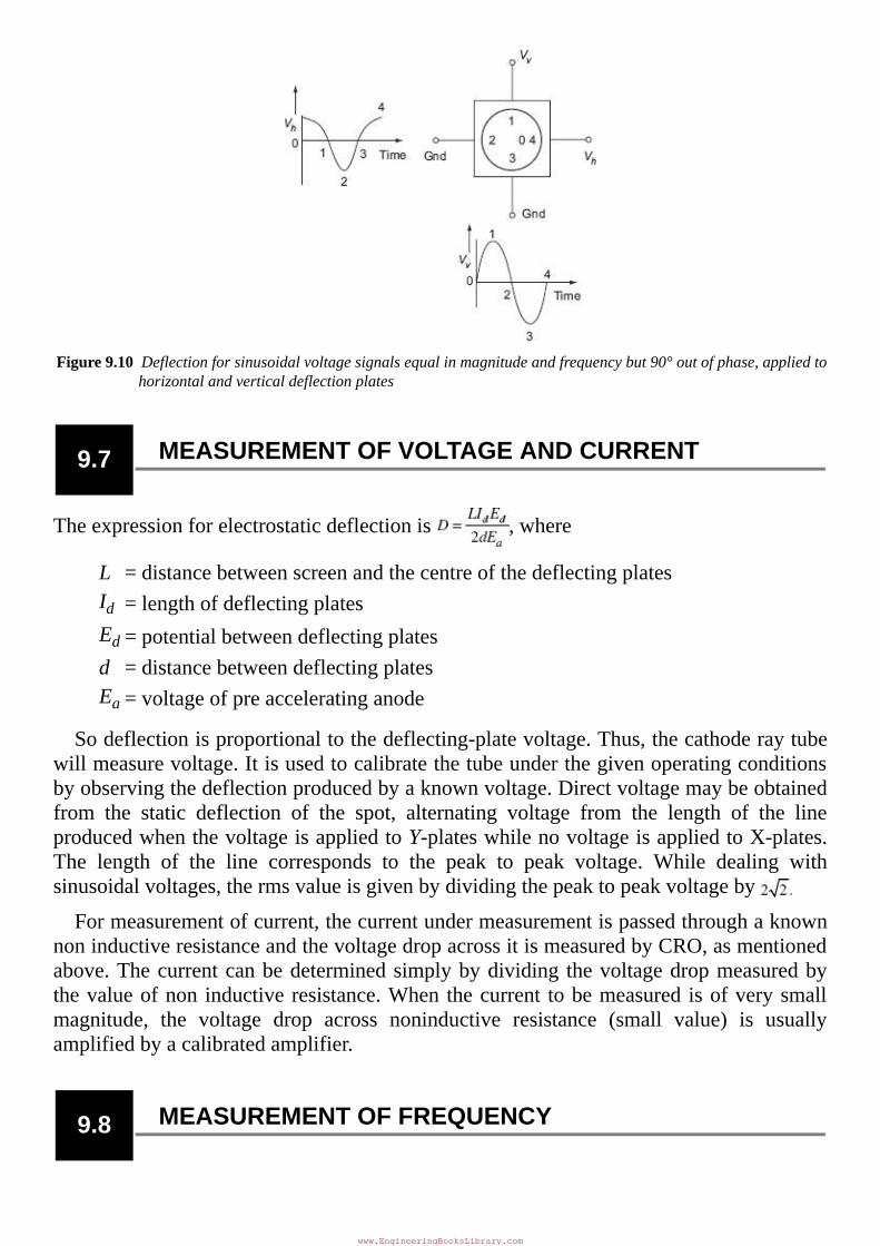
Figure9.10Deflectionforsinusoidalvoltagesignalsequalinmagnitudeandfrequencybut90°outofphase,appliedtohorizontalandverticaldeflectionplates
9.7 MEASUREMENTOFVOLTAGEANDCURRENT
Theexpressionforelectrostaticdeflectionis ,where
L = distancebetweenscreenandthecentreofthedeflectingplatesId = lengthofdeflectingplatesEd = potentialbetweendeflectingplatesd = distancebetweendeflectingplatesEa = voltageofpreacceleratinganode
Sodeflectionisproportionaltothedeflecting-platevoltage.Thus,thecathoderaytubewillmeasurevoltage.Itisusedtocalibratethetubeunderthegivenoperatingconditionsbyobservingthedeflectionproducedbyaknownvoltage.Directvoltagemaybeobtainedfrom the static deflection of the spot, alternating voltage from the length of the lineproducedwhenthevoltageisappliedtoY-plateswhilenovoltageisappliedtoX-plates.The length of the line corresponds to the peak to peak voltage. While dealing withsinusoidalvoltages,thermsvalueisgivenbydividingthepeaktopeakvoltageby
Formeasurementofcurrent,thecurrentundermeasurementispassedthroughaknownnoninductiveresistanceandthevoltagedropacrossitismeasuredbyCRO,asmentionedabove.Thecurrentcanbedeterminedsimplybydividing thevoltagedropmeasuredbythevalueofnon inductiveresistance.When thecurrent tobemeasured isofverysmallmagnitude, the voltage drop across noninductive resistance (small value) is usuallyamplifiedbyacalibratedamplifier.
9.8 MEASUREMENTOFFREQUENCY
www.EngineeringBooksLibrary.com
It is interesting to consider the characteristicsofpatterns that appearon the screenof aCROwhensinusoidalvoltagesare simultaneouslyapplied to thehorizontal andverticalplates.ThesepatternsarecalledLissajouspatterns.
Lissajous patterns may be used for accurate measurement of frequency. The signal,whose frequency is to bemeasured, is applied to theY-plates.An accurately calibratedstandard variable frequency source is used to supply voltage to the X-plates, with theinternalsweepgeneratorswitchedoff.Thestandardfrequencyisadjusteduntilthepatternappears as a circle or an ellipse, indicating that both signals areof the same frequency.Whereitisnotpossibletoadjustthestandardsignalfrequencytotheexactfrequencyoftheunknownsignal,thestandardisadjustedtoamultipleorsubmultipleofthefrequencyoftheunknownsourcesothatthepatternappearsstationary.
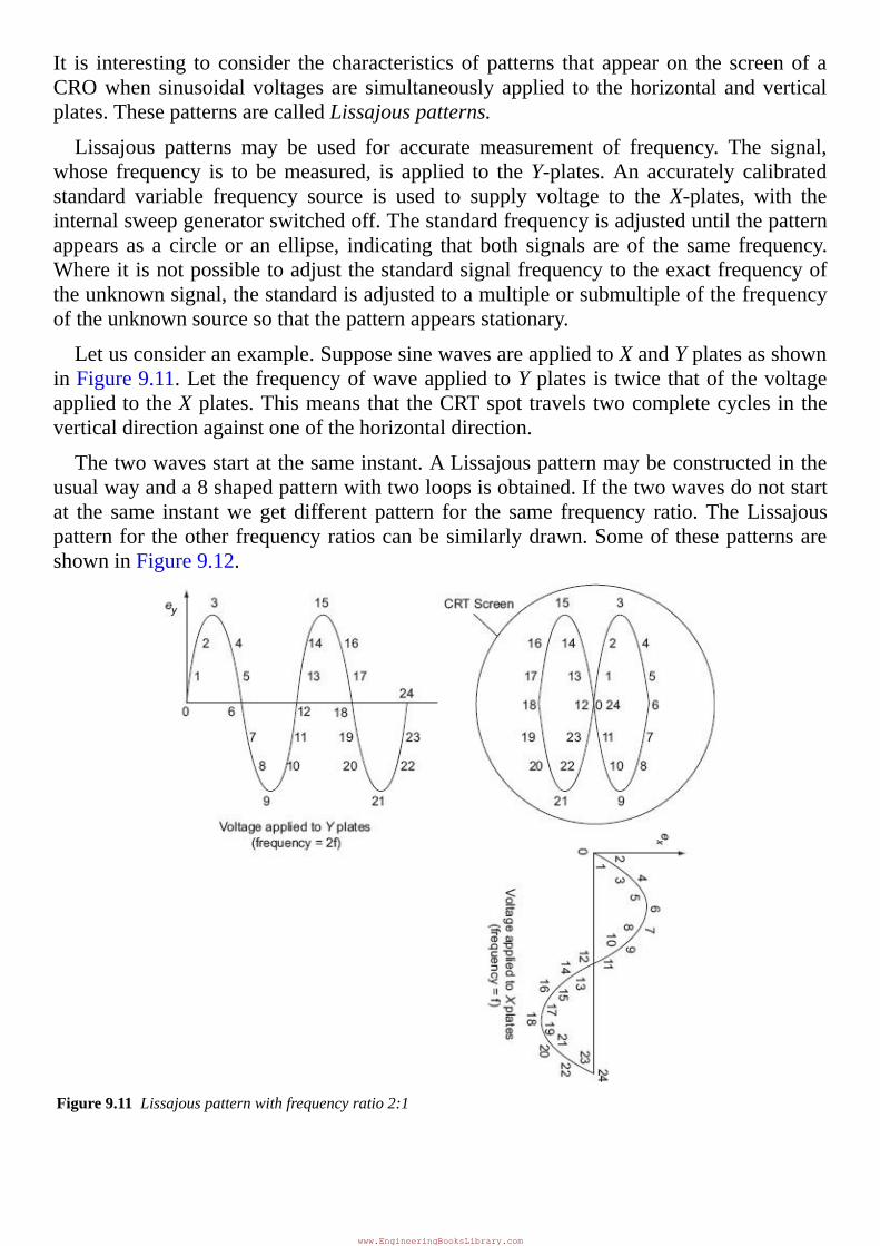
Letusconsideranexample.SupposesinewavesareappliedtoXandYplatesasshowninFigure9.11.LetthefrequencyofwaveappliedtoYplatesistwicethatofthevoltageappliedtotheXplates.ThismeansthattheCRTspottravelstwocompletecyclesintheverticaldirectionagainstoneofthehorizontaldirection.
Thetwowavesstartatthesameinstant.ALissajouspatternmaybeconstructedintheusualwayanda8shapedpatternwithtwoloopsisobtained.Ifthetwowavesdonotstartat the same instantweget different pattern for the same frequency ratio.TheLissajouspatternfortheotherfrequencyratioscanbesimilarlydrawn.SomeofthesepatternsareshowninFigure9.12.
Figure9.11Lissajouspatternwithfrequencyratio2:1
www.EngineeringBooksLibrary.com
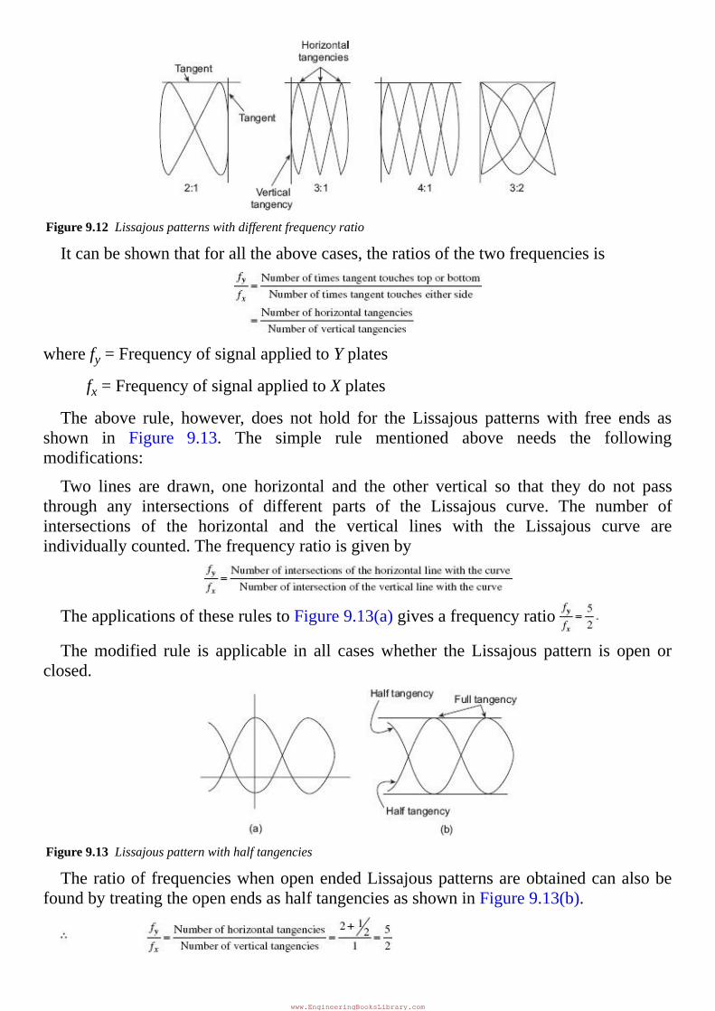
Figure9.12Lissajouspatternswithdifferentfrequencyratio
Itcanbeshownthatforalltheabovecases,theratiosofthetwofrequenciesis
wherefy=FrequencyofsignalappliedtoYplates
fx=FrequencyofsignalappliedtoXplates
The above rule, however, does not hold for the Lissajous patternswith free ends asshown in Figure 9.13. The simple rule mentioned above needs the followingmodifications:
Two lines are drawn, one horizontal and the other vertical so that they do not passthrough any intersections of different parts of the Lissajous curve. The number ofintersections of the horizontal and the vertical lines with the Lissajous curve areindividuallycounted.Thefrequencyratioisgivenby
TheapplicationsoftheserulestoFigure9.13(a)givesafrequencyratio
Themodified rule is applicable in all caseswhether the Lissajous pattern is open orclosed.
Figure9.13Lissajouspatternwithhalftangencies
TheratiooffrequencieswhenopenendedLissajouspatternsareobtainedcanalsobefoundbytreatingtheopenendsashalftangenciesasshowninFigure9.13(b).
www.EngineeringBooksLibrary.com
Thereare some restrictionson the frequencieswhichcanbeapplied to thedeflectionplates. One obviously, is that the CRO must have the bandwidth required for thesefrequencies. The other restriction is that the ratio of the two frequencies should not besuchastomakethepatterntoocomplicatedotherwisedeterminationoffrequencywouldbecomedifficult.Asarule,ratiosashighas10:1andaslowas10:9canbedeterminedcomfortably.
9.9 MEASUREMENTOFPHASEDIFFERENCE
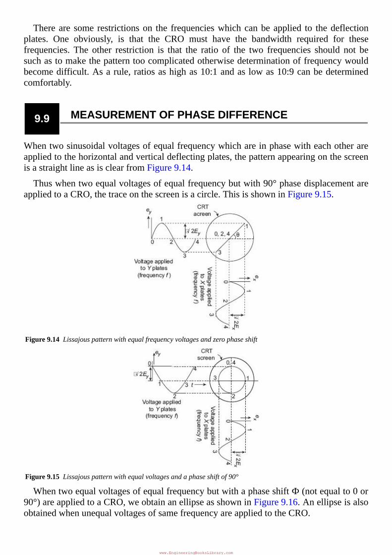
Whentwosinusoidalvoltagesofequalfrequencywhichareinphasewitheachotherareappliedtothehorizontalandverticaldeflectingplates,thepatternappearingonthescreenisastraightlineasisclearfromFigure9.14.
Thuswhentwoequalvoltagesofequalfrequencybutwith90°phasedisplacementareappliedtoaCRO,thetraceonthescreenisacircle.ThisisshowninFigure9.15.
Figure9.14Lissajouspatternwithequalfrequencyvoltagesandzerophaseshift
Figure9.15Lissajouspatternwithequalvoltagesandaphaseshiftof90°
WhentwoequalvoltagesofequalfrequencybutwithaphaseshiftФ(notequalto0or90°)areappliedtoaCRO,weobtainanellipseasshowninFigure9.16.AnellipseisalsoobtainedwhenunequalvoltagesofsamefrequencyareappliedtotheCRO.
www.EngineeringBooksLibrary.com
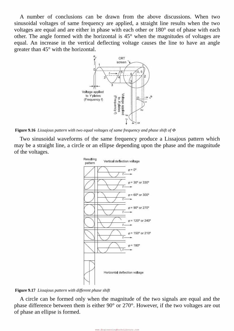
A number of conclusions can be drawn from the above discussions. When twosinusoidal voltages of same frequency are applied, a straight line resultswhen the twovoltagesareequalandareeitherinphasewitheachotheror180°outofphasewitheachother.Theangle formedwith thehorizontal is45°when themagnitudesofvoltagesareequal. An increase in the vertical deflecting voltage causes the line to have an anglegreaterthan45°withthehorizontal.
Figure9.16LissajouspatternwithtwoequalvoltagesofsamefrequencyandphaseshiftofФ
Two sinusoidalwaveforms of the same frequency produce a Lissajous patternwhichmaybeastraightline,acircleoranellipsedependinguponthephaseandthemagnitudeofthevoltages.
Figure9.17Lissajouspatternwithdifferentphaseshift
Acirclecanbeformedonlywhenthemagnitudeof thetwosignalsareequalandthephasedifferencebetweenthemiseither90°or270°.However,ifthetwovoltagesareoutofphaseanellipseisformed.
www.EngineeringBooksLibrary.com
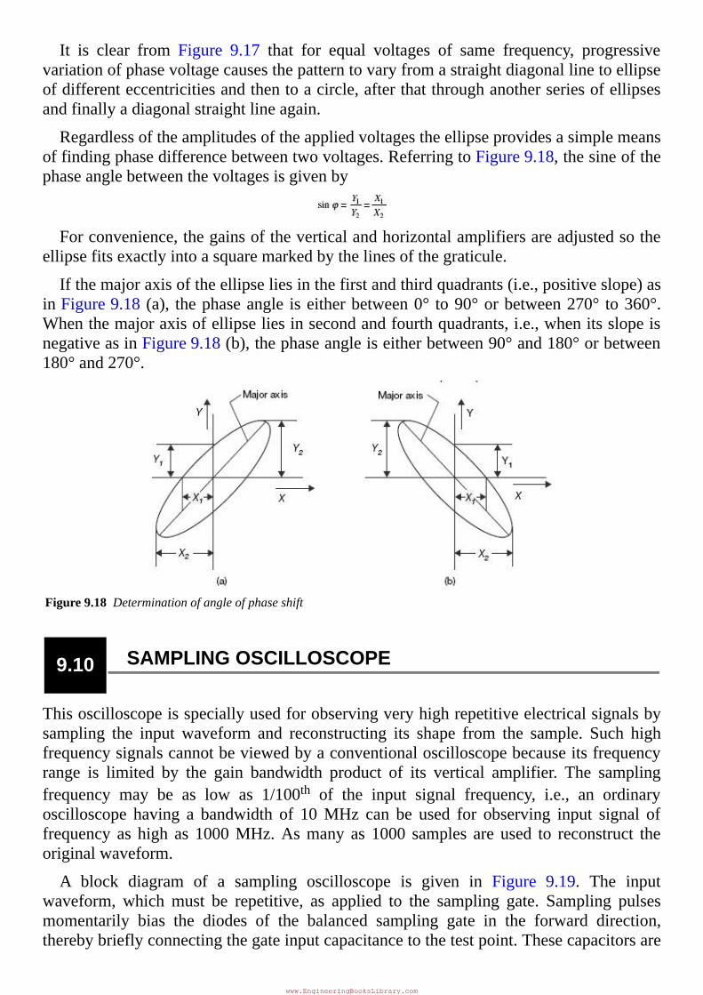
It is clear from Figure 9.17 that for equal voltages of same frequency, progressivevariationofphasevoltagecausesthepatterntovaryfromastraightdiagonallinetoellipseofdifferenteccentricitiesandthentoacircle,afterthatthroughanotherseriesofellipsesandfinallyadiagonalstraightlineagain.
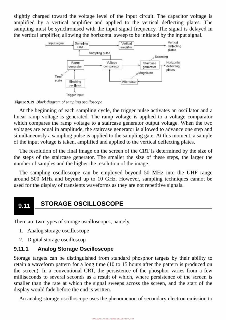
Regardlessoftheamplitudesoftheappliedvoltagestheellipseprovidesasimplemeansoffindingphasedifferencebetweentwovoltages.ReferringtoFigure9.18,thesineofthephaseanglebetweenthevoltagesisgivenby
Forconvenience,thegainsoftheverticalandhorizontalamplifiersareadjustedsotheellipsefitsexactlyintoasquaremarkedbythelinesofthegraticule.
Ifthemajoraxisoftheellipseliesinthefirstandthirdquadrants(i.e.,positiveslope)asinFigure9.18(a), thephaseangle iseitherbetween0° to90°orbetween270° to360°.Whenthemajoraxisofellipseliesinsecondandfourthquadrants,i.e.,whenitsslopeisnegativeasinFigure9.18(b),thephaseangleiseitherbetween90°and180°orbetween180°and270°.
Figure9.18Determinationofangleofphaseshift
9.10 SAMPLINGOSCILLOSCOPE
Thisoscilloscopeisspeciallyusedforobservingveryhighrepetitiveelectricalsignalsbysampling the input waveform and reconstructing its shape from the sample. Such highfrequencysignalscannotbeviewedbyaconventionaloscilloscopebecauseitsfrequencyrange is limited by the gain bandwidth product of its vertical amplifier. The samplingfrequency may be as low as 1/100th of the input signal frequency, i.e., an ordinaryoscilloscope having a bandwidth of 10MHz can be used for observing input signal offrequency as high as 1000MHz.Asmany as 1000 samples are used to reconstruct theoriginalwaveform.
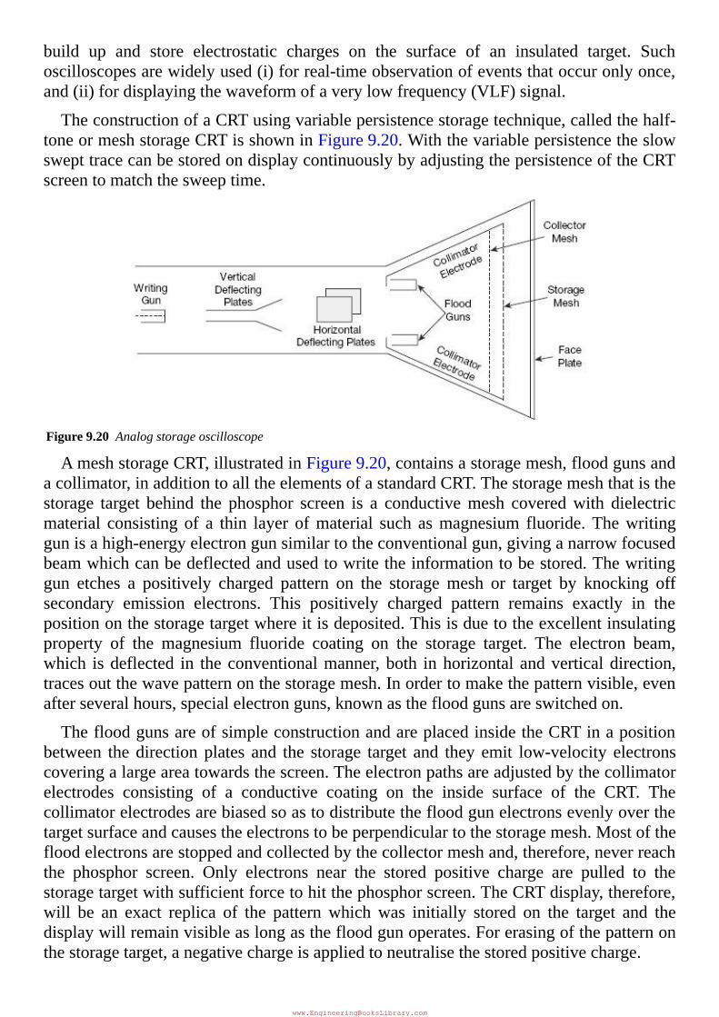
A block diagram of a sampling oscilloscope is given in Figure 9.19. The inputwaveform, whichmust be repetitive, as applied to the sampling gate. Sampling pulsesmomentarily bias the diodes of the balanced sampling gate in the forward direction,therebybrieflyconnectingthegateinputcapacitancetothetestpoint.Thesecapacitorsare
www.EngineeringBooksLibrary.com
slightly charged toward the voltage level of the input circuit. The capacitor voltage isamplified by a vertical amplifier and applied to the vertical deflecting plates. Thesamplingmustbesynchronisedwiththeinputsignalfrequency.Thesignal isdelayedintheverticalamplifier,allowingthehorizontalsweeptobeinitiatedbytheinputsignal.
Figure9.19Blockdiagramofsamplingoscilloscope
Atthebeginningofeachsamplingcycle,thetriggerpulseactivatesanoscillatorandalinear ramp voltage is generated. The ramp voltage is applied to a voltage comparatorwhichcompares therampvoltage toastaircasegeneratoroutputvoltage.When the twovoltagesareequalinamplitude,thestaircasegeneratorisallowedtoadvanceonestepandsimultaneouslyasamplingpulseisappliedtothesamplinggate.Atthismoment,asampleoftheinputvoltageistaken,amplifiedandappliedtotheverticaldeflectingplates.
TheresolutionofthefinalimageonthescreenoftheCRTisdeterminedbythesizeofthe steps of the staircase generator. The smaller the size of these steps, the larger thenumberofsamplesandthehighertheresolutionoftheimage.
The sampling oscilloscope can be employed beyond 50 MHz into the UHF rangearound 500MHz and beyond up to 10GHz.However, sampling techniques cannot beusedforthedisplayoftransientswaveformsastheyarenotrepetitivesignals.
9.11 STORAGEOSCILLOSCOPE
Therearetwotypesofstorageoscilloscopes,namely,
1.Analogstorageoscilloscope
2.Digitalstorageoscilloscop
9.11.1AnalogStorageOscilloscopeStorage targets can be distinguished from standard phosphor targets by their ability toretainawaveformpatternforalongtime(10to15hoursafterthepatternisproducedonthe screen). In a conventional CRT, the persistence of the phosphor varies from a fewmilliseconds to several seconds as a result ofwhich,where persistence of the screen issmaller than the rate atwhich the signal sweeps across the screen, and the start of thedisplaywouldfadebeforetheendiswritten.
Ananalogstorageoscilloscopeusesthephenomenonofsecondaryelectronemissionto
www.EngineeringBooksLibrary.com
build up and store electrostatic charges on the surface of an insulated target. Suchoscilloscopesarewidelyused(i)forreal-timeobservationofeventsthatoccuronlyonce,and(ii)fordisplayingthewaveformofaverylowfrequency(VLF)signal.
TheconstructionofaCRTusingvariablepersistencestoragetechnique,calledthehalf-toneormeshstorageCRTisshowninFigure9.20.WiththevariablepersistencetheslowswepttracecanbestoredondisplaycontinuouslybyadjustingthepersistenceoftheCRTscreentomatchthesweeptime.
Figure9.20Analogstorageoscilloscope
AmeshstorageCRT,illustratedinFigure9.20,containsastoragemesh,floodgunsandacollimator,inadditiontoalltheelementsofastandardCRT.Thestoragemeshthatisthestorage target behind the phosphor screen is a conductivemesh coveredwith dielectricmaterial consisting of a thin layer ofmaterial such asmagnesium fluoride.Thewritinggunisahigh-energyelectrongunsimilartotheconventionalgun,givinganarrowfocusedbeamwhichcanbedeflectedandusedtowritetheinformationtobestored.Thewritinggun etches a positively charged pattern on the storagemesh or target by knocking offsecondary emission electrons. This positively charged pattern remains exactly in thepositiononthestoragetargetwhereitisdeposited.Thisisduetotheexcellentinsulatingproperty of the magnesium fluoride coating on the storage target. The electron beam,which isdeflected in theconventionalmanner,both inhorizontal andverticaldirection,tracesoutthewavepatternonthestoragemesh.Inordertomakethepatternvisible,evenafterseveralhours,specialelectronguns,knownasthefloodgunsareswitchedon.
ThefloodgunsareofsimpleconstructionandareplacedinsidetheCRTinapositionbetween thedirectionplates and the storage target and they emit low-velocity electronscoveringalargeareatowardsthescreen.Theelectronpathsareadjustedbythecollimatorelectrodes consisting of a conductive coating on the inside surface of the CRT. Thecollimatorelectrodesarebiasedsoastodistributethefloodgunelectronsevenlyoverthetargetsurfaceandcausestheelectronstobeperpendiculartothestoragemesh.Mostofthefloodelectronsarestoppedandcollectedbythecollectormeshand,therefore,neverreachthe phosphor screen. Only electrons near the stored positive charge are pulled to thestoragetargetwithsufficientforcetohitthephosphorscreen.TheCRTdisplay,therefore,will be an exact replica of the pattern whichwas initially stored on the target and thedisplaywillremainvisibleaslongasthefloodgunoperates.Forerasingofthepatternonthestoragetarget,anegativechargeisappliedtoneutralisethestoredpositivecharge.
www.EngineeringBooksLibrary.com
For achieving variable persistence, the erase voltage is applied in the form of pulsesinsteadof a steadydcvoltage; byvarying thewidthof thesepulses the rateof erase iscontrolled.
9.11.2DigitalStorageOscilloscopeThere are a number of distinct disadvantages of the analog storage oscilloscope. Thesedisadvantagesarelistedbelow:
1. There is a finite amount of time that the storage tube can preserve a storedwaveform.Eventually,thewaveformwillbelost.Thepowertothestoragetubemustbepresentaslongastheimageistobestored.
2. Thetraceofastoragetubeis,generally,notasfineasanormalcathoderaytube.Thus,thestoredtraceisnotascrispasaconventionaloscilloscopetrace.
3. Thewriting rateof the storage tube is less thanaconventionalcathode ray tube,whichlimitsthespeedofthestorageoscilloscope.
4. Thestoragecathoderay tube isconsiderablymoreexpensive thanaconventionaltubeandrequiresadditionalpowersupplies.
5. Only one image can be stored. If two traces are to be compared, theymust besuperimposedonthesamescreenanddisplayedtogether.
A superior method if trace storage is the digital storage oscilloscope (DSO). In thistechnique,thewaveformtobestoredisdigitised,storedinadigitalmemoryandretrievedfordisplayonthestorageoscilloscope.Thestoredwaveformiscontinuallydisplayedbyrepeatedly scanning the stored waveform and, therefore, a conventional CRT can beemployedforthedisplayandthussomeofthecostoftheadditionalcircuitryfordigitizingandstoringtheinputwaveformisoffset.Thestoreddisplaycanbedisplayedindefinitelyaslongasthepowerisappliedtothememory,whichcanbesuppliedwithasmallbattery.Thedigitisedwaveformcanbefurtheranalysedbyeither theoscilloscopeorbyloadingthecontentof thememoryintoacomputer.Someofthedigitalstorageoscilloscopeuse12-bit converter, giving 0.025% resolution and 0.1% accuracy on voltage and timereadings, which are better than the 2.5% of analog storage oscilloscopes. Split screencapabilities(simultaneouslydisplayingliveanalogtracesandreplayedstoredones)enableeasycomparisonofthetwosignals.Pre-triggercapabilityisalsoanimportantadvantage.Thedisplayofstoreddata ispossible inbothamplitudeversus time,andX-Ymodes. InadditiontothefastmemoryreadoutemployedforCRTdisplay,aslowreadoutispossiblefordevelopinghardcopywithexternalplotters.
Theonlydrawbackofdigitalstorageoscilloscopesislimitedbandwidthbythespeedoftheiranalog-to-digitalconverters(ADCs).However,20MHzdigitisingratesavailableonsome oscilloscopes yield a bandwidth of 5 MHz, which is adequate for most of theapplications.
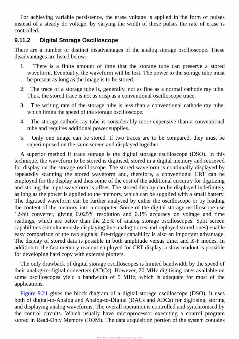
Figure 9.21 gives the block diagram of a digital storage oscilloscope (DSO). It usesbothofdigital-to-AnalogandAnalog-to-Digital(DACsandADCs)fordigitising,storinganddisplayinganalogwaveforms.Theoveralloperationiscontrolledandsynchronisedbythe control circuits. Which usually have microprocessor executing a control programstoredinRead-OnlyMemory(ROM).Thedataacquisitionportionofthesystemcontains
www.EngineeringBooksLibrary.com
a sample-and-hold (S/H) and a analog-to-digital converter that repetitively samples anddigitized the input signal at a rate determined by the sample clock, and transmits thedigitiseddatatomemoryforstorage.Thecontrolcircuitmakessurethatsuccessivedatapoints are stored in successivememory locationsbycontinuallyupdating thememory’saddresscounter.
Figure9.21BlockdiagramofDigitalStorageOscilloscope(DSO)
Whenmemoryisfull,thenextdatapointfromtheADCisstoredinthefirstmemorylocation writing over the old data, and so on for successive data points. This dataacquisition and the storage process continue until the control circuit receives a triggersignal from either the input waveform (internal trigger) or an external trigger source.Whenthetriggeringoccurs,thesystemstopsacquiringdatafurtherandentersthedisplaymodeofoperation,inwhichallorpartofthememorydataisrepetitivelydisplayedontheCathodeRayTube(CRT).
IndisplayoperationtwoDACsareemployedforprovidingtheverticalandhorizontaldeflecting voltages for the cathode ray tube. Data from memory produce the verticaldeflection of the electron beam, while the time base counter provides the horizontaldeflection in the form of a staircase sweep signal. The control circuits synchronize thedisplayoperationbyincrementingthememoryaddresscounterandthetimebasecounterat the same time so that eachhorizontal stepof theelectronbeam is accompaniedbyanew data value from the memory to the vertical DAC. The counters are continuouslyrecycledsothatthestoreddatapointsarerepetitivelyre-plottedonthescreenoftheCRT.The screendisplay consists of discrete dots representing thevariousdatapoints but thenumberofdotsisusuallysolarge(typically1000ormore)thattheytendtoblendtogetherandappeartobeacontinuouswaveform.
Thedisplayoperationistransmittedwhentheoperatorpressesafrontpanelbuttonthatcommendsthedigitalstorageoscilloscopetobeginanewdataacquisitioncycle.
9.12 MULTI-INPUTOSCILLOSCOPES
Modem oscilloscopes have the multi-input facility. They display the multi input
www.EngineeringBooksLibrary.com
simultaneously. Two inputs is most generally used, although four and eight inputs areavailable for special applications. There are two primary types: single beam and dualbeam.Asinglebeamcanbeconvertedintoseveraltraces.Adualbeam,ontheotherhandmay also subsequently be converted into a further number of traces. Two inputoscilloscopesaredescribed in thischapter, although theprinciplesareapplicable toanynumberofinputs.
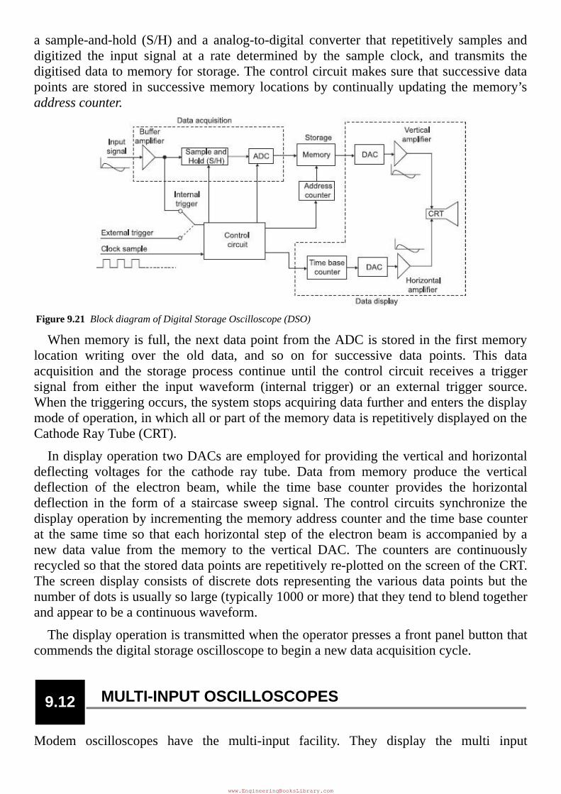
9.12.1DualTraceOscilloscopesTheblockdiagramof a dual trace oscilloscope is shown inFigure9.22. There are twoseparate vertical input channels, A and B, and these use separate attenuator andpreamplifierstages.Thereforetheamplitudeofeachinput,asviewedontheoscilloscope,can be individually controlled. After preamplification, the two channels meet at theelectronic switch. This has the ability to pass one channel at a time into the verticalamplifier,viathedelayline.
Figure9.22Blockdiagramofadualtraceoscilloscope
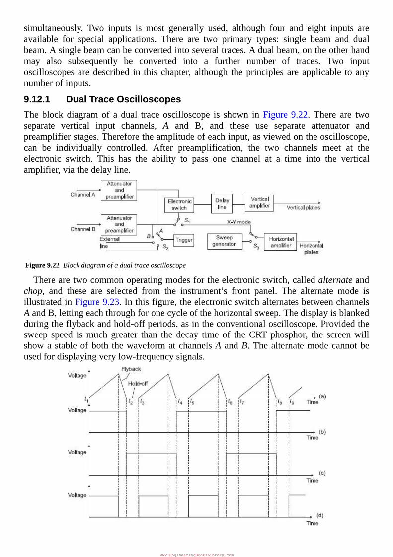
Therearetwocommonoperatingmodesfortheelectronicswitch,calledalternateandchop, and these are selected from the instrument’s front panel. The alternate mode isillustratedinFigure9.23.Inthisfigure,theelectronicswitchalternatesbetweenchannelsAandB,lettingeachthroughforonecycleofthehorizontalsweep.Thedisplayisblankedduringtheflybackandhold-offperiods,asintheconventionaloscilloscope.Providedthesweep speed ismuchgreater than the decay timeof theCRTphosphor, the screenwillshowastableofboth thewaveformatchannelsAandB.Thealternatemodecannotbeusedfordisplayingverylow-frequencysignals.
www.EngineeringBooksLibrary.com
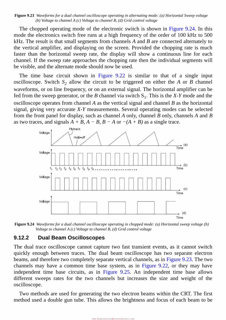
Figure9.23Waveformsforadualchanneloscilloscopeoperatinginalternatingmode:(a)HorizontalSweepvoltage(b)VoltagetochannelA(c)VoltagetochannelB,(d)Gridcontrolvoltage
Thechoppedoperatingmodeof theelectronicswitch isshowninFigure9.24. In thismodetheelectronicsswitchfreerunsatahighfrequencyoftheorderof100kHzto500kHz.TheresultisthatsmallsegmentsfromchannelsAandBareconnectedalternatelytotheverticalamplifier,anddisplayingon thescreen.Provided thechopping rate ismuchfaster than the horizontal sweep rate, the displaywill show a continuous line for eachchannel.Ifthesweeprateapproachesthechoppingratethentheindividualsegmentswillbevisible,andthealternatemodeshouldnowbeused.
The time base circuit shown in Figure 9.22 is similar to that of a single inputoscilloscope. Switch S2 allow the circuit to be triggered on either the A orB channelwaveforms,oronlinefrequency,oronanexternalsignal.Thehorizontalamplifiercanbefedfromthesweepgenerator,ortheBchannelviaswitchS1.ThisistheX-YmodeandtheoscilloscopeoperatesfromchannelAastheverticalsignalandchannelBasthehorizontalsignal,givingveryaccurateX-Ymeasurements.Severaloperatingmodescanbeselectedfromthefrontpanelfordisplay,suchaschannelAonly,channelBonly,channelsAandBastwotraces,andsignalsA+B,A−B,B−Aor−(A+B)asasingletrace.
Figure9.24Waveformsforadualchanneloscilloscopeoperatinginchoppedmode:(a)Horizontalsweepvoltage(b)VoltagetochannelA(c)VoltagetochannelB,(d)Gridcontrolvoltage
9.12.2DualBeamOscilloscopesThedual traceoscilloscopecannotcapture two fast transientevents, as it cannot switchquickly enough between traces. The dual beam oscilloscope has two separate electronbeams,andthereforetwocompletelyseparateverticalchannels,asinFigure9.23.Thetwochannels may have a common time base system, as in Figure 9.22, or they may haveindependent time base circuits, as in Figure 9.25. An independent time base allowsdifferent sweeps rates for the two channels but increases the size and weight of theoscilloscope.
TwomethodsareusedforgeneratingthetwoelectronbeamswithintheCRT.Thefirstmethodusedadoubleguntube.Thisallowsthebrightnessandfocusofeachbeamtobe
www.EngineeringBooksLibrary.com
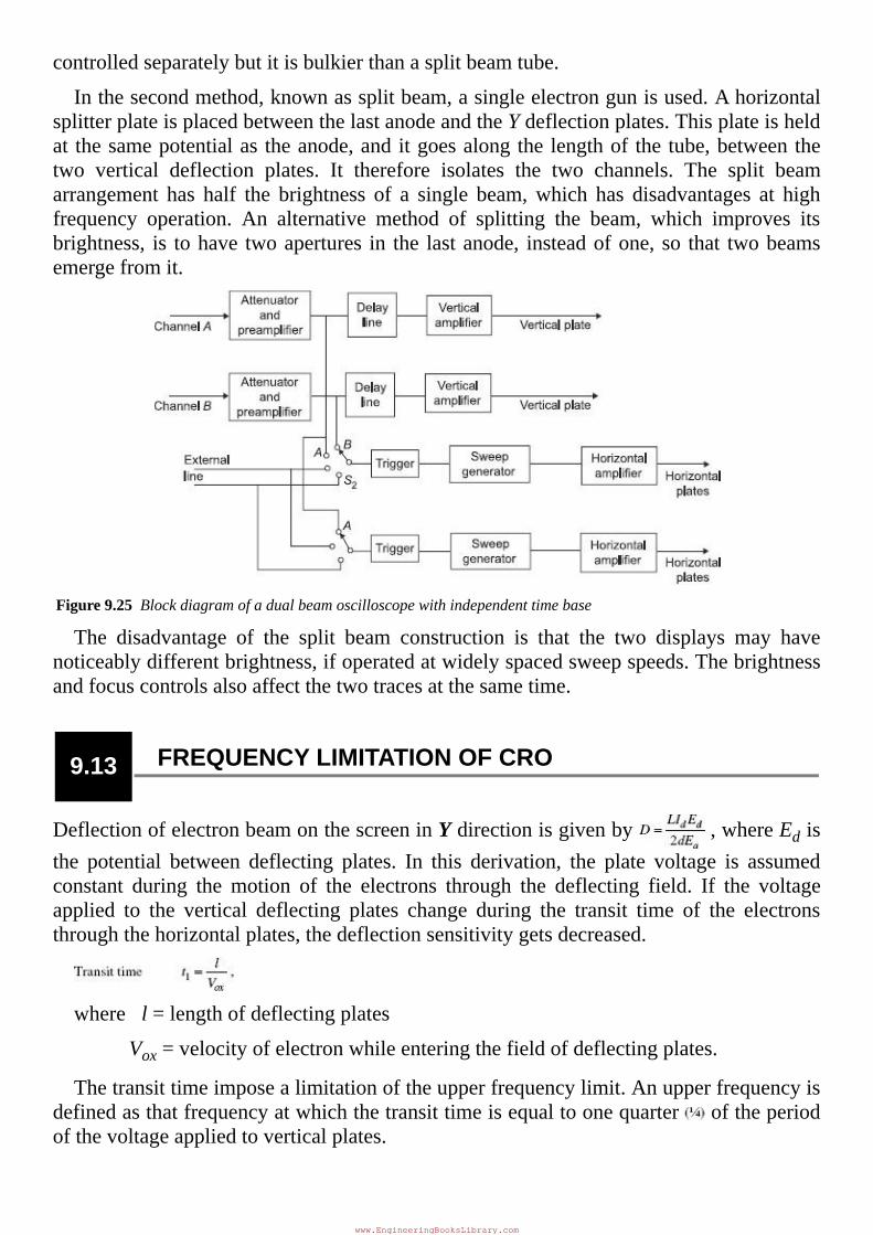
controlledseparatelybutitisbulkierthanasplitbeamtube.
Inthesecondmethod,knownassplitbeam,asingleelectrongunisused.AhorizontalsplitterplateisplacedbetweenthelastanodeandtheYdeflectionplates.Thisplateisheldat thesamepotentialas theanode,anditgoesalongthelengthof thetube,betweenthetwo vertical deflection plates. It therefore isolates the two channels. The split beamarrangement has half the brightness of a single beam,which has disadvantages at highfrequency operation. An alternative method of splitting the beam, which improves itsbrightness, is tohave twoapertures in the lastanode, insteadofone,so that twobeamsemergefromit.
Figure9.25Blockdiagramofadualbeamoscilloscopewithindependenttimebase
The disadvantage of the split beam construction is that the two displays may havenoticeablydifferentbrightness,ifoperatedatwidelyspacedsweepspeeds.Thebrightnessandfocuscontrolsalsoaffectthetwotracesatthesametime.
9.13 FREQUENCYLIMITATIONOFCRO
DeflectionofelectronbeamonthescreeninYdirectionisgivenby ,whereEdisthe potential between deflecting plates. In this derivation, the plate voltage is assumedconstant during the motion of the electrons through the deflecting field. If the voltageapplied to the vertical deflecting plates change during the transit time of the electronsthroughthehorizontalplates,thedeflectionsensitivitygetsdecreased.
wherel=lengthofdeflectingplates
Vox=velocityofelectronwhileenteringthefieldofdeflectingplates.
Thetransittimeimposealimitationoftheupperfrequencylimit.Anupperfrequencyisdefinedasthatfrequencyatwhichthetransittimeisequaltoonequarter oftheperiodofthevoltageappliedtoverticalplates.
www.EngineeringBooksLibrary.com
Thefrequencyrangeoftheoscilloscopecanbeincreasedbysub-dividingthedeflectingplatesinanumberofsectionsinthepathofelectronbeam.Thevoltagebeingmeasuredisapplied to the vertical plates through an iterative network, whose propagation timecorrespondstothevelocityofelectron;therebythevoltageappliedtotheverticalplatesismadetosynchronisewiththevelocityofthebeam.TheuseofthistechniqueallowstheCROtobeuseduptofrequenciesof500MHzandabove.
EXERCISE
Objective-typeQuestions1.ThetimebasesignalinaCROis
(a)asinusoidalsignal
(b)asawtoothsignal
(c)asquarewavesignal
(d)atriangularwavesignal
2.InCRTaquadagcarries
(a)secondaryemissionelectrons
(b)sweepvoltage
(c)aqueoussolutionofgraphite
(d)noneofthese
3.InaCRO,thesawtoothvoltageisappliedatthe
(a)cathode
(b)acceleratinganode
(c)verticaldeflectingplates
(d)horizontaldeflectingplates
4.ThepurposeofthesynchronisingcontrolinaCROisto
(a)adjusttheamplitudeofdisplay
(b)controltheintensityofthespot
(c)focusthespotonthescreen
(d)lockthedisplayofsignal
5.Retraceperiodforanidealsawtoothwaveformis
(a)0second
(b)equaltotracingperiod
(c)infinite
(d)noneofthese
6.InaCRT,thehighestpositivepotentialisgivento
(a)cathode
(b)focusingelectrodes
(c)verticaldeflectingplates
(d)post-deflectionaccelerationanode
www.EngineeringBooksLibrary.com
7.TheXandYinputsofaCROarerespectivelyVsinωtand−Vsinωt.TheresultingLissajouspatternwillbe
(a)astraightline
(b)acircle
(c)theshapeof8
(d)anellipse
8.Thepatternsusedtomeasurephaseandfrequencywithacathoderayoscilloscopearecalled
(a)Faraday’spattern
(b)Ohm’spatterns
(c)Lissajouspattern
(d)Phillipspattern
9. Thevoltage10 cosωtandV cos (ωt +α) are applied to theX andY plates of aCRO.TheLissajous figureobservedonthescreenisastraightlineof60°tothepositiveaxis.Then
(a)V=10,α=60°
(b)V=10,α=0°
(c)V=10 ,α=60°
(d)V=10 ,α=0°
10.Samplingoscilloscopesarespeciallydesignedtomeasure
(a)veryhighfrequency
(b)verylowfrequency
(c)microwavefrequency
(d)noneofthese
11.Whichofthefollowingstatementsisnotcorrectforastorage-typeoscilloscope?
(a)Secondaryemissionelectronsetchapositivelychargedpattern.
(b)Thefloodgunsusedfordisplay,emithighvelocityelectrons.
(c)Thefloodgunsareplacedbetweenthedeflectionplatesandstoragetarget.
(d)Thestoragetargetisaconductivemeshcoveredwithmagnesiumfluoride.
12.Inadigitaloscilloscope,theA/Dconvertersareusually
(a)ramptype
(b)flashtype
(c)integratingtype
(d)successiveapproximatetype
13.Adoublebeamoscilloscopehas
(a)twoscreens
(b)twoelectronguns
(c)twodifferentphosphorcoatings
(d)onewaveformdividedintotwoparts
14.TwoequalvoltagesofsamefrequencyappliedtotheXandYplatesofaCRO,produceacircleonthescreen.Thephasedifferencebetweenthetwovoltagesis
(a)150°
(b)90°
(c)60°
(d)30°
www.EngineeringBooksLibrary.com
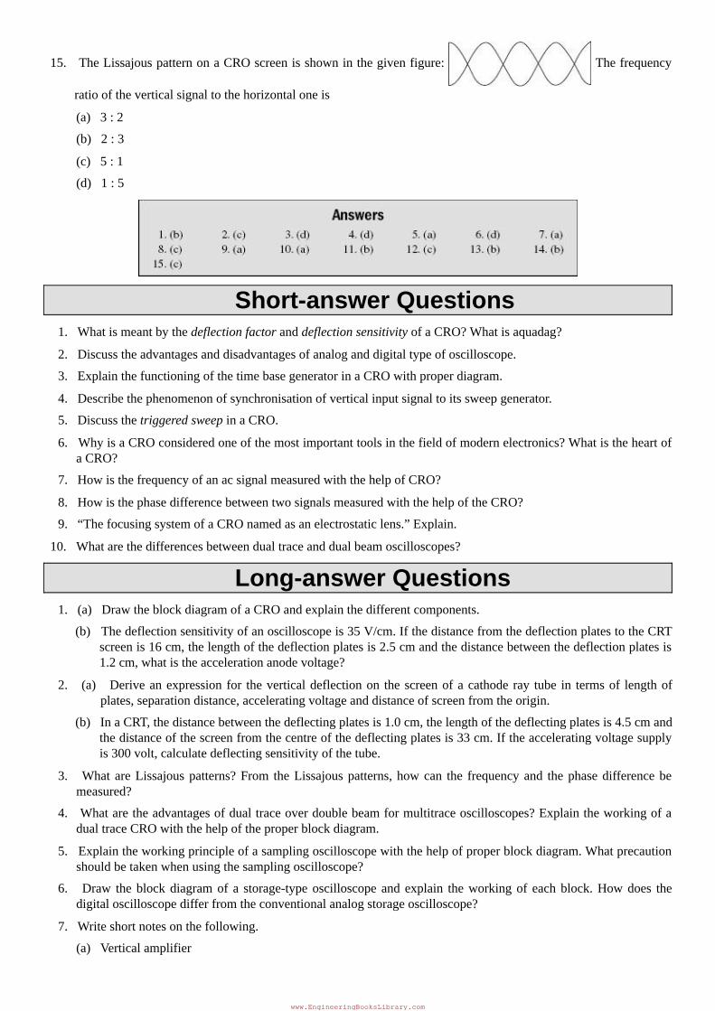
15.TheLissajouspatternonaCROscreenisshowninthegivenfigure: Thefrequency
ratiooftheverticalsignaltothehorizontaloneis
(a)3:2
(b)2:3
(c)5:1
(d)1:5
Short-answerQuestions1.WhatismeantbythedeflectionfactoranddeflectionsensitivityofaCRO?Whatisaquadag?
2.Discusstheadvantagesanddisadvantagesofanaloganddigitaltypeofoscilloscope.
3.ExplainthefunctioningofthetimebasegeneratorinaCROwithproperdiagram.
4.Describethephenomenonofsynchronisationofverticalinputsignaltoitssweepgenerator.
5.DiscussthetriggeredsweepinaCRO.
6.WhyisaCROconsideredoneofthemostimportanttoolsinthefieldofmodernelectronics?WhatistheheartofaCRO?
7.HowisthefrequencyofanacsignalmeasuredwiththehelpofCRO?
8.HowisthephasedifferencebetweentwosignalsmeasuredwiththehelpoftheCRO?
9.“ThefocusingsystemofaCROnamedasanelectrostaticlens.”Explain.
10.Whatarethedifferencesbetweendualtraceanddualbeamoscilloscopes?
Long-answerQuestions1.(a)DrawtheblockdiagramofaCROandexplainthedifferentcomponents.
(b)Thedeflectionsensitivityofanoscilloscopeis35V/cm.IfthedistancefromthedeflectionplatestotheCRTscreenis16cm,thelengthofthedeflectionplatesis2.5cmandthedistancebetweenthedeflectionplatesis1.2cm,whatistheaccelerationanodevoltage?
2. (a) Deriveanexpression for theverticaldeflectionon thescreenofacathoderay tube in termsof lengthofplates,separationdistance,acceleratingvoltageanddistanceofscreenfromtheorigin.
(b)InaCRT,thedistancebetweenthedeflectingplatesis1.0cm,thelengthofthedeflectingplatesis4.5cmandthedistanceofthescreenfromthecentreofthedeflectingplatesis33cm.Iftheacceleratingvoltagesupplyis300volt,calculatedeflectingsensitivityofthetube.
3. What areLissajouspatterns?From theLissajouspatterns,howcan the frequencyand thephasedifferencebemeasured?
4.Whataretheadvantagesofdualtraceoverdoublebeamformultitraceoscilloscopes?ExplaintheworkingofadualtraceCROwiththehelpoftheproperblockdiagram.
5.Explaintheworkingprincipleofasamplingoscilloscopewiththehelpofproperblockdiagram.Whatprecautionshouldbetakenwhenusingthesamplingoscilloscope?
6. Draw theblockdiagramof a storage-typeoscilloscopeandexplain theworkingof eachblock.Howdoes thedigitaloscilloscopedifferfromtheconventionalanalogstorageoscilloscope?
7.Writeshortnotesonthefollowing.
(a)Verticalamplifier
www.EngineeringBooksLibrary.com
(b)Electromagneticfocusing
(c)Delayline
(d)FrequencyandphasemeasurementbyCRO
(e)Highfrequencyoscilloscope
(f)Freerunningsweep
(g)Oscilloscopelimitations
www.EngineeringBooksLibrary.com
Related Documents