DEDICATED TO ELECTRICAL PROGRESS 1,1,13113 VEIV ELECTRIC LI BRARY YO z.1Y FOR ENGINEERS, ELECTRICIANS ALL ELECTRICAL WORKERS MECHANICS AND STUDENTS Presenting in simplest, concise form the fundamental principles, rules and applications of applied electricity. Fully illustrated with diagrams and sketches. Including calculations and tables for ready reference. Helpful Questions and answers. Trial tests for practice. study and review. Design, construction, operation and maintenance of modern electrical machines and appliances. Based on the best knowledge and experience of applied electricity. .óry FRANK D. GRAHAM, B.S., M.S.,M.E.,E.E. THEO.AUDEI. S. CO., PUBLISHERS 6S WEST 23rd STREET, NEW YORK,II.S.A.

Welcome message from author
This document is posted to help you gain knowledge. Please leave a comment to let me know what you think about it! Share it to your friends and learn new things together.
Transcript
DEDICATED TO ELECTRICAL PROGRESS
1,1,13113
VEIV ELECTRIC LI BRARY
YO z.1Y FOR ENGINEERS, ELECTRICIANS ALL ELECTRICAL WORKERS MECHANICS AND STUDENTS
Presenting in simplest, concise form the fundamental principles, rules and applications of applied electricity. Fully illustrated with diagrams and sketches. Including calculations and tables for ready reference. Helpful Questions and answers. Trial tests for practice. study and review. Design, construction, operation and maintenance of modern electrical machines and appliances. Based on the best knowledge and experience of applied electricity.
.óry FRANK D. GRAHAM, B.S., M.S.,M.E.,E.E.
THEO.AUDEI. S. CO., PUBLISHERS 6S WEST 23rd STREET, NEW YORK,II.S.A.
Copyrighted 1929
Theo. Audel & Co.
Printed 1935
Printed in the United Stote's of Americo
Audel's New Electric Library
LEG TRW '
Rf FRI6ERATIOII Hf ATIN6 X-RAY PI ATIEN6 WEEDING-RVpS COMPRESSORS DOMESTIC -EARN A171 IAIECES X
RADIO TELEPHONE TELEGRAPH BELLS -SIGNALS MOTION PICTURE TALKIES LIGHTING &LU1IWQW1I
ELECTRIC RAILWAYS
SIGNALS ELEVATORS U0USTS-CfA11ES 6As En61NE AUTO AE RO I6NIT ION STARTERSVI
Note
ELECTRIC CALCULATOR IIRENNINEERS AMICI4 TAGS PRACTICAL I. I( MATHEMATICS
REFERENCE
WIRING I10115EL I6HT
PcWER CIRCUITS HIGH TE1N51011 TAAELSMIS5ION
PLANS CALCULATIONS
CODE VII
NEW ELECTRIC
DUCT I OVARY CYCLtPE DIA OF WORDS TEMAS FWASES
LIBRARY INDEx XII
FUrC IMf NTAL PRINCIPLES pro RUIES°' ELECTRICITY MAGNETISM ARMATURE VVInDMRRSS
1
V
DYNAMOS D CMOTDRS CON`TRUGTION INSTALLATION MARIE MANGE
TROUBLE SIKXPrIN6II
-r
4
IV ' As` G M
OTORS
....1...r ~Dines REGOITECTlN6 FHINTEIwwGE CONVE RTERS S1YINtESfU5E5
CIRCUIT BREAKERS V
Mt AYS CONDENSERS REGULATORS RECTIFIERS METERS swii IR CIARRS
POWER STATK
PRACTICE VI
ELECTRICAL TESTING INSTRULtmS
TESTS STOR E BATT
CIN
«REPAIRSnl
ALTERNATING CURRENT PRINCIPLES
DIAGRAMS PFACTOR
ALTERNATORS TRAKYORNERSIV
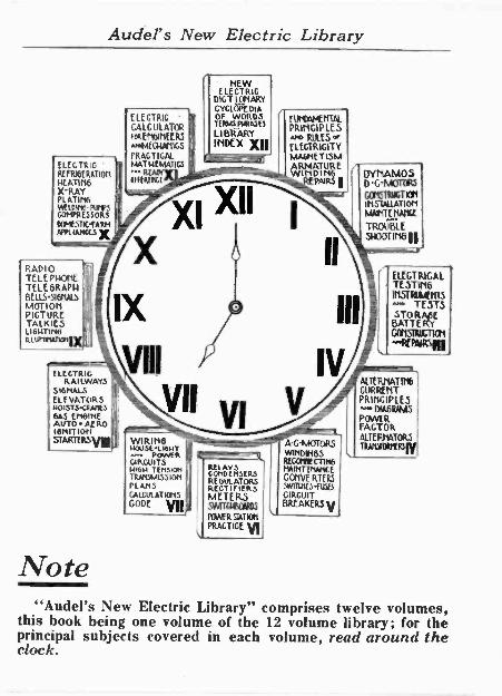
"Audel's New Electric Library" comprises twelve volumes, this book being one volume of the 12 volume library; for the principal subjects covered in each volume, read around the clock.
TO SEPARATELY EXCITED
WINDING
*EXCITER
SEPARATELY -EXCITED WINDING
COMPENSATING WINDING .
COLLECTOR RINGS BRUSH
RECTIFIER
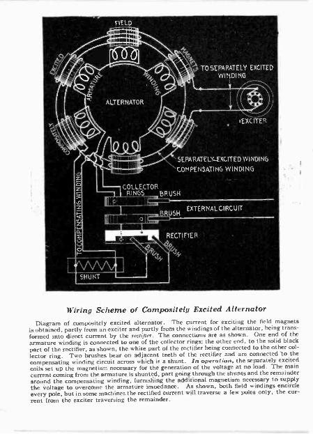
Wiring Scheme of Compositely Excited Alternator
Diagram of compositely excited alternator. The current (or exciting the field magnets is obtained, partly from an exciter and partly from the windings of the alternator, being trans- formed into direct current by the rectifier. The connections are as shown. One end of the armature winding is connected to one of the collector rings; the other end, to the solid black part of the rectifier, as shown, the white part of the rectifier being connected to the other col-
lector ring. Two brushes bear on adjacent teeth of the rectifier and are connected to the compensating winding circuit across which it a shunt. In operation, the separately excited coils set up the magnetism necessary for the generation of the voltage at no load. The main current coming from the armature.is shunted, part going through the shunts and the remainder around the compensating winding, furnishing the additional magnetism necessary to supply the voltage to overcome the armature impedance. As shown, both field windings encircle every pole, but in some machines the rectified current will traverse a few poles only, the cur- rent from the exciter traversing the remainder.

Foreword This series is dedicated to Electrical
Progress-to all who have helped and those who may in the coming years help to bring further under human control and service to humanity this mighty force of the Creator.
The Electrical Age has opened new problems to all connected with modern industry, making a thorough working knowledge of the fundamental princi- ples of applied electricity necessary.
The author, following the popular appeal for practical knowledge, has prepared this progressive series for the electrical worker and student; for all who are seeking electrical knowledge as a life profession; and for those who find that there is a gap in their training and knowledge of Electricity.
Simplicity is the keynote throughout this series. From this progressive step-by-step method of instruction and explanation, the reader can easily gain a thorough knowledge of modern electrical practice in line with the best information and experi- ence.
The author and publishers here gratefully acknowledge the hearty and generous help and co-operation of all those who have aided in developing this helpful series of Educators.
The series will speak for itself and "those who run may read."
The Publishers.

Readers' Information Finder
How to Use This Book
Finder
IMPORTANT
To quickly and easily find information on any subject, read over the general chapter headings as shown in the large type- this brings the reader's attention to the general classification of information in this book.
Each chapter is progressive, so that if the reader will use the outline following each general chapter heading, he will readily come to the information desired and the page on which to find it.
Get the habit of using this Index-it will quickly reveal a vast mine of valuable information.
"An hour with a book would have brought to your mind, Tice secret that look the whole year to find;
The facts that you learned al enormous expense, Were all on a library shelf to commence."

Readers' Information Finder. Vol. IV
FINDER Pages
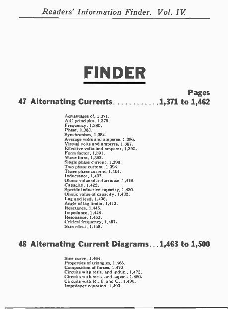
47 Alternating Currents. .......1,371 to 1,462
Advantages of, 1,371. A.C.principles, 1,375. Frequency, 1.380. Phase, 1,383. Synchronism, 1.384. Average volts and amperes. 1,386. Virtual volts and amperes. 1,387. Effective volts and amperes, 1,390. Form factor, 1,391. Wave form, 1,392. Single phase current, 1,398. Two phase current, 1.398. Three phase current, 1,404. Inductance, 1,407. Ohmic value of inductance, 1,419. Capacity, 1,422. Specific inductive capacity, 1,430. Ohmic value of capacity, 1,432. Lag and lead. 1,436. Angle of lag limits, 1,443. Reactance, 1,445. Impedance, 1,448. Resonance, 1,453. Critical frequency, 1.457. Skin effect, 1.458.
48 Alternating Current Diagrams... 1,463 to 1,500
Sine curve, 1,464. Properties of triangles, 1,465. Composition of forces. 1.470. Circuits with resis. and induc., 1,472. Circuits with resis. and capac., 1.480. Circuits with R., I. and C., 1.490. Impedance equation, 1,493.
Readers' Information Finder. Vol. IV
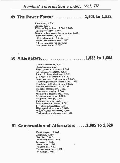
49 The Power Factor 1,501 to 1,532 Definition, 1,504. Range, 1,504. Effect of lag or lead.. 1,504, 1,508. The power curve, 1,505. Synchromism; power factor unity, 1,506. Wattless current, 1,510. Effect of capacity, 1.519. Power loss in condenser, 1,520. Kilovolt ampere rating, 1,522. Low power factor, 1,527.
50 Alternators ....1,533 to 1,604 Use of alternators, 1,533. Classification, 1,534. Single phase alternators, 1,535. Polyphase alternators, 1,538. 6 and 12 phase windings, 1,542. Belt driven alternators, 1,543. Direct connected alternators, 1,547. Revolving armature alternators. 1,551. Revolving field alternators, 1.555. Motion; relative matter, 1,556. Inductor alternators, 1,559. Hunting or singing. 1,564. Monocyclic alternators, 1.565. Armature reactance, 1,569. Magnetic leakage, 1,575. Field excitation, 1,576. Slow speed alternators, 1,582. Fly wheel alternators. 1,584. High speed alternators, 1.585. Water wheel alternators, 1,586. Turbine driven alternators, 1,592.
51 Construction of Alternators 1,605 to 1,626 Field magnets, 1,605. Magneto. 1,610. Rectifier, 1,610. Revolving field, 1,613. Slip ring, 1,614. Armatures, 1,619. Punchings, 1,620. Exciter armature, 1,622. Windings, 1,625.
Readers' Information Finder. Vol. IV
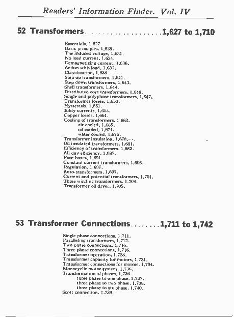
52 Transformers 1,627 to 1,710 Essentials, 1,627. Basic principles, 1,628. The induced voltage, 1,631. No load current, 1,634. Demagnetizing current, 1,636. Action with load, 1,637. Classi ficat ion. 1,638. Step up transformers, 1,641. Step down transformers, 1,643. Shell transformers, 1,644. Distributed core transformers. 1,646. Single and po'yphase transformers, 1,647. Transformer losses, 1,650. Hysteresis, 1,651. Eddy currents, 1,654. Copper losses. 1,661. Cooling of transformers, 1,663.
air cooled, 1.665. oil cooled. 1,674. water cooled, 1,675.
Transformer insulation, 1.678r...., Oil insulated transformers, 1,681. Efficiency of transformers. 1,682. All day efficiency, 1.687. Fuse boxes, 1,691. Constant current transformers, 1,693. Regulation, 1,697. Auto -transformers, 1,697. Current and potential transformers, 1,701. Three winding transformers. 1,704. Transformer oil dryer. 1,705.
53 Transformer Connections ...1,711 to 1,742 Single phase connections, 1,711. Paralleling transformers, 1,712. Two phase connections, 1,716. Three phase connections, 1,716. Transformer operation. 1,728. Transformer capacity for motors, 1.731. Transformer connections for motors, 1,734. Nlonocyclic motor system. 1,736. Transformation of phases, 1,736.
three phase to one phase, 1,737. three phase to two phase, 1,738. three phase to six phase, 1,740.
Scott connection. 1.739.
Readers' Information Finder. Vol. IV
54 Alternating Current Motors (Classification) 1,743 and 1,744
55 Synchronous Motors ...1,745 to 1,776 The term "synchronous," 1,745. Principles. 1,746. Musical analogy, 1,745. Operation, 1,761. Disadvantages, 1,762. Advantages. 1,763. Adapt at ion, 1,764. Hunting, 1,765. Magnetic clutch type, 1,767. Characteristics, 1,771. Super -synchronous motors, 1,773.
56 Squirrel Cage Motors 1,777 to 1,854 Operation, 1,779. The term "asynchronous." 1.783. Slip, 1,783. Polyphase induction motors, 1,791. Notating magnetic field, 1,794. Two phase rotating field, 1,797. Three phase rotating field, 1;804. Magnetic poles in armature, 1,807. How induction motor works, 1,811. '
Starting conditions, 1,822. Evolution of squirrel cage arm, 1,825. Operation of squirrel cage, 1,828. Field magnets, 1,838. Field windings, 1,839. Coil grouping, 1.842. Starting induction motors, 1,844. Power factor of induction motors, 1,848. Speed and torque. 1,849. Efficiency and power factor, 1,851.
-
Alternating Currents 1,371
CHAPTER 47
Alternating Currents The word "Alternating" is used with a large number of
electrical and magnetic quantities to denote that their magni- tudes vary continuously , passing repeatedly through a definite cycle of values in a definite interval of time.
As applied to the flow of electricity, an alternating current may be defined as: A current which reverses its direction in a periodic manner, rising from zero to maximum strength, returning to zero, and then going through similar variations in strength in the opposite direction; these changes comprise the cycle which is repeated with great rapidity.
The properties of alternating currents are more complex than those of continuous currents, and their behavior more difficult to predict. This arises from the fact that the magnetic effects are of far more importance than those of steady currents. With the latter the magnetic effect is constant, and has no reactive influence on the current when the latter is once established. The lines of force, however, produced by alternating currents are changing as rapidly as the current itself, and they thus induce electric pressures in neighboring circuits, and even in adjacent parts of the same circuit. This inductive influence in alternating currents renders their action very different from that of continuous current.
Ques. What are the advantages of alternating current over direct current?
Ans. The reduced cost of transmission by use of high voltage transformers, greater simplicity of generators and
DY
NA
MO
INC
. LA
MP
A
RC
C
OO
KIN
G
ELE
CT
RO
P
LAT
ING
MA
GN
ET
WIR
E
IRO
N
CO
RE
t
ST
OR
AG
E
BA
TT
ER
Y
+
-
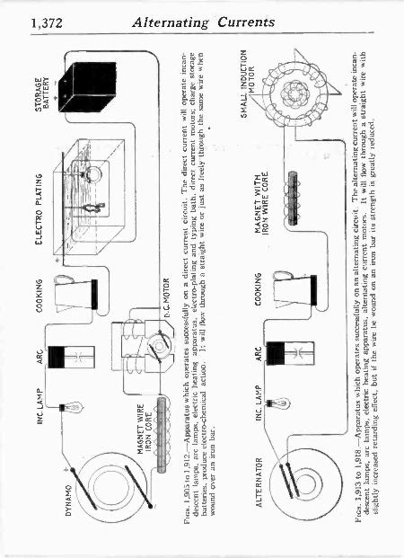
Fin
s. 1
,905
to 1
,912
.-A
ppar
atus
whi
ch
oper
ates
suc
cess
fully
on
a cu
rren
t ci
rcui
t. T
he d
irect
cur
rent
w
ill o
pera
te i
ncan
-
desc
ent
lam
ps,
arc
lam
ps,
elec
tric
hea
ting
appa
ratu
s, e
lect
ro -p
latin
g an
d ty
ping
bat
h, d
irect
cur
rent
mot
ors;
cha
rge
stor
age
batte
ries,
pro
duce
ele
ctro
-che
mic
al a
ctio
n.
It w
ill f
low
th
roug
h a
stra
ight
wire
or
just
as
free
lyth
roug
h th
e sa
me
wire
whe
n
wou
nd o
ver
an i
ron
bar.
ALT
ER
NA
TO
R
AR
C
CO
OK
ING
M
AG
NE
T W
ITH
IR
ON
WIR
E C
OR
E
.111
1,i1
1111
.
SM
ALL
IN
DU
CT
ION
M
OT
OR
Ftc
s. 1
,913
to
1,91
8.-A
ppar
atus
whi
ch o
pera
tes
succ
essf
ully
on
an a
ltern
atin
g ci
rcui
t. T
he a
ltern
atin
g cu
rren
t will
ope
rate
inc
an-
desc
ent
lam
ps,
arc
lam
ps,
eléc
tric
hea
ting
appa
ratu
s, a
ltern
atin
g cu
rren
t m
otor
s.
It w
ill f
low
th
roug
h a
stra
ight
w
ire w
ith
slig
htly
inc
reas
ed r
etar
ding
effe
ct,
but
if th
e w
ire b
e w
ound
on
iro
n ba
r its
str
engt
h is
gre
atly
red
uced
.
Alternating Currents 1,373
motors, facility of transforming from one voltage to another (either higher or lower) for different purposes.
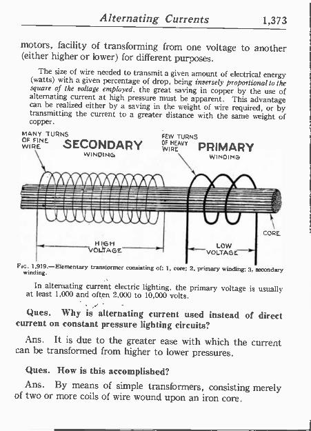
The size of wire needed to transmit a given amount of electrical energy (watts) with a given percentage of drop, being inversely proportional to the square of the voltage employed, the great saving in copper by the use of alternating current at high pressure must be apparent. This advantage can be realized either by a saving in the weight of wire required, or by transmitting the current to a greater distance with the same weight of copper.
MANY TURNS OF FINREE SECONDARY WI
FEW TURNS OF
WIREAVY PRIMARY
WINOING \ WINOIN3
omfoo
.M.,11=1r--
HIGH VOLICAGE
FIG. 1,919.-Elementary transformer consisting of: 1, core; 2, primary winding: 3, secondary winding.
CORE
LOW VOLTAGE-
In alternating current electric lighting, the primary voltage is usually at least -1,000 and often 2,000 to 10,000 volts.
Ques. Why is alternating current used instead of direct current on constant pressure lighting circuits?
Ans. It is due to the greater ease with which the current can be transformed from higher to lower pressures.
Ques. How is this accomplished? Ans. By means of simple transformers, consisting merely
of two or more coils of wire wound upon an iron core.
1,374 Alternating Currents
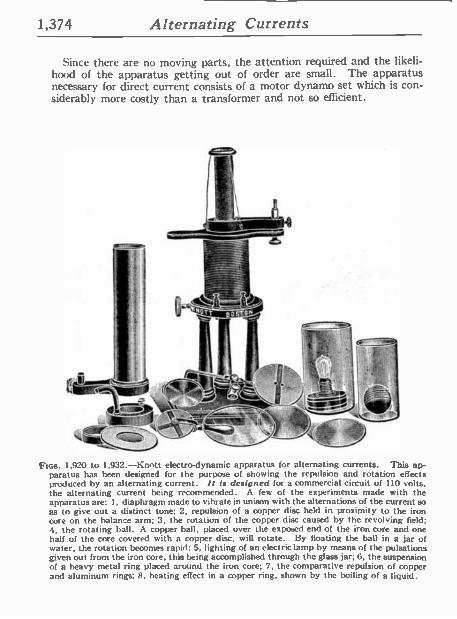
Since there are no moving parts, the attention required and the likeli- hood of the apparatus getting out of order are small. The apparatus necessary for direct current consists of a motor dynamo set which is con- siderably more costly than a transformer and not so efficient.
'11,
1 .., /é1~0 r ` ' + - ; . -=
5"l -_ .
FIGS. 1,920 to 1.932.-Knott electrodynamic apparatus for alternating currents. This ap- paratus has been designed for the purpose of showing the repulsion and rotation effects produced by an alternating current. It is designed for a commercial circuit of 110 volts, the alternating current being recommended. A few of the experiments made with the apparatus are: 1, diaphragm made to vibrate in unison with the alternations of the current so as to give out a distinct tone; 2, repulsion of a copper disc held in proximity to the iron core on the balance arm; 3, the rotation of the copper disc caused by the revolving field; 4, the rotating ball. A copper ball, placed over the exposed end of the iron core and one half of the core covered with a copper disc, will rotate. By floating the ball in a jar of water, the rotation becomes rapid; 5. lighting of an electric lamp by means of the pulsations given out from the iron core, this being accomplished through the glass jar; 6, the suspension of a heavy metal ring placed around the iron core; 7, the comparative repulsion of copper and aluminum rings; 8, heating effect in a copper ring, shown by the boiling of a liquid.
Alternating Currents 1,375
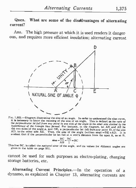
Ques. What are some of the dis *lvantages of alternating current?
Ans. The high pressure at which it is used renders it danger. ous, and requires more efficient insulation; alternating current
D
A C NATURAL SINE OF ANGLE 4
\ FIG. 1,933.-Diagram illustrating the sine of an angle. In order to understand the sine curve. it is necessary to know the meaning of the sine of an angle. This is defined as the ratio of the perpendicular let fall from any point in one side of the angle to the other side divided by the
hypothenuse of the triangle thus formed. For instance, in the diagram, let AD and AE he the two sides of the angle 0, and DE, a perpendicular let fall from any point D, of the side AD, to the other side AE. Then, the sine of the angle (written sings) =DE=AD. It is
evident that if the perpendicular be let (all at a unit's distance from the apex A. as at B, i3C BC
Wings= =13C All 1
This line BC, is called the natural sine of the angle, and its values for different angles are given in the table on page 921.
cannot be used for such purposes as electro -plating, charging storage batteries, etc.
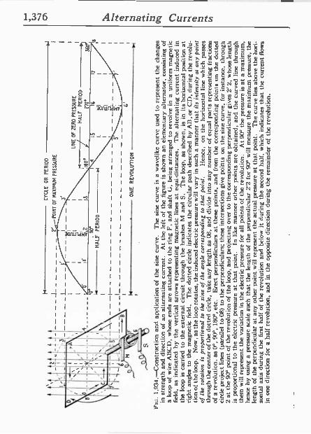
Alternating Current Principles.-In the operation of a dynamo, as explained in Chapter 13, alternating currents are
1,376 Alternating Currents
Y I I
I I
I I
1 I
I I
I I
I I
I I
I I
_ I_Y_ T-1
I I
Alternating Currents 1,377
generated in the armature winding and are changed into direct current by the action of the commutator. It was therefore necessary in that chapter, in presenting the basic principles of the dynamo, to explain the generation of alternating currents at length, and the graphic method of representing the alternat- ing current cycle by the sine curve. In ordzr to avoid unneces- sary repetition, the reader should carefully review the above mentioned chapter before continuing further. The diagram fig. 399, showing the construction and application of the sine
o'
ORDINATE
I Iso.
r 4
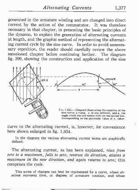
Ftc. 1,935.-Diagram illustrating the equation of the sine curve: y =sino. y, is any ordinate, and 4,, the angle which the cod makes with the horizontal line, corresponding to the particular value of y, taken.
curve to the alternating current, is, however, for convenience here shown enlarged in fig. 1,934.
In the diagram the various alternating current terms are graphically defined.
The alternating current, as has been explained, rises from zero to a maximum, falls to zero, reverses its direction, attains a maximum in the new direction, and again returns to zero; this comprises the cycle.
This series of changes can best be represented by a curve, whose ab- scissae represent time, or degrees of armature rotation, and whose
1,378 Alternating Currents
tt tt \,
- .
RtGÑT SWING I
.¡
,
C t LEFTSWIN6
ss : -. A ,
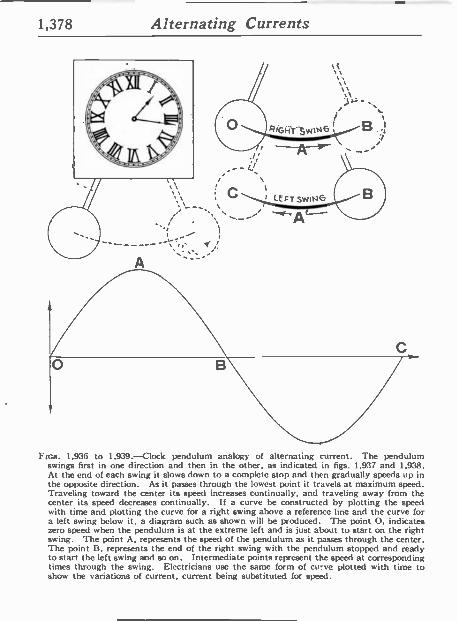
FIGS. 1,936 to 1,939.-Clock pendulum analogy of alternating current. The pendulum swings first in one direction and then in the other, as indicated in figs. 1,937 and 1,938. At the end of each swing it slows down to a complete stop and then gradually speeds up in the opposite direction. As it passes through the lowest point it travels at maximum speed. Traveling toward the center its speed increases continually, and traveling away from the center its speed decreases continually. If a curve be constructed by plotting the speed with time and plotting the curve for a right swing above a reference line and the curve for a left swing below it, a diagram such as shown will be produced. The point O. indicates zero speed when the pendulum is at the extreme left and is just about to start on the right swing. The point A, represents the speed of the pendulum as it passes through the center. The point B. represents the end of the right swing with the pendulum stopped and ready to start the left swing and so on. Intermediate points represent the speed at corresponding times through the swing. Electricians use the same form of curve plotted with time to show the variations of current, current being substituted for speed.
Alternating Currents 1,379
ordinates, either current or pressure. The curve usually chosen for this purpose is the sine curve, as shown in fig. 1,934, because it closely agrees with that given by most alternators.
The equation of the sine curve is y= sin k
in which y, is any ordinate, and 4,, the angle of the corresponding position of the coil in which the current is being generated as illustrated in fig. 1,935.
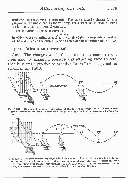
Ques. What is an alternation?
Ans. The changes which the current undergoes in rising from zero to maximum pressure and returning back to zero; that is, a single positive or negative "wave" or half periad, as shown in fig. 1,940.
i}1
ll/ iso° 360'
rt--ONE ALTERNATION N\
Fw. 1,940-Diagram showing one alternation of the current in which the latter varies from zero to maximum and hack to zero while the generating loop ABCD, makes one half revolu- tion.
'AMPLITUDE
N t80° 270° 360° a i
FIG. 1,941.-Diagram illustrating amplitude of the current. The current reaches its amplitude or maximum value in one quarter period from its point of zero value, as, for instance, while the generating loop moves from position ABCD, to A'B'C'D'. At three-quarter revolu- tion, the current reaches its maximum value in the opposite direction.
1,380 Alternating Currents
Ques. What is the amplitude of the current?
Ans. The greatest value of the current strength attained during the cycle.
The foregoing definitions are also illustrated in fig. 1,934.
Ques. Define the term "period."
Ans. This is the time of one cycle of the alternating current.
ISO REVOLUTION; PER MINUTE
FREQUENCY f50x4m6 60 - . 60
S CYCLES PER REV. OF ARMATURE -NUM9E11 OF POLES _ Q_
11111 11>jh
900 REVOLUTIONS PER MINUTE
EI6HT POLE ALTERNATOR =REQUENCY 60
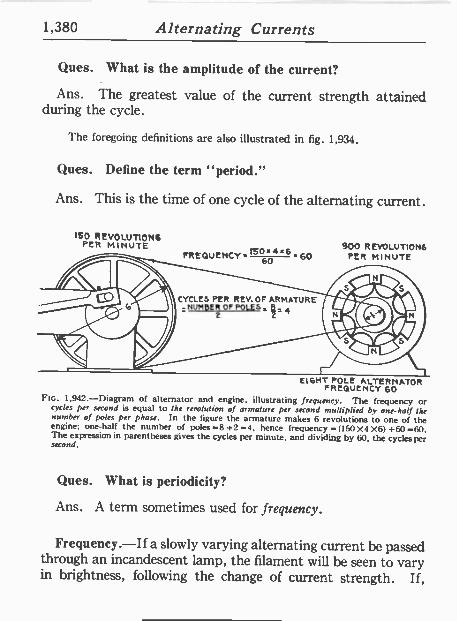
Fib. 1,942.-Diagram of alternator and engine, illustrating frequency. The frequency or cycles per second is equal to the revolution of armature per second multiplied by one-half the number of poles per phase. In the figure the armature makes 6 revolutions to one of the engine; one-half the number of poles =8 +2 =4, hence frequency = (150 X4 X6) +60 =60. The expression in parentheses gives the cycles per minute, and dividing by 60, the cycles per second.
Ques. What is periodicity?
Ans. A term sometimes used for frequency.
Frequency.-If a slowly varying alternating current be passed through an incandescent lamp, the filament will be seen to vary in brightness, following the change of current strength. If,
Alternating Currents 1,381
however, the alternations take place more rapidly than about 50 to 60 per second, the eye cannot follow the variations and the lamp appears to burn steadily. Hence it is important to con- sider the rate at which the alternations take place, or as it is called, the frequency, which is defined as: the number of cycles per second.
In a two pole machine, the frequency is the same as the number of revolutions per second, but in multipolar machines, it is greater in propor- tion to the number of pairs of poles per phase.
ISO REVOLUTIONS PER MINUTE
900 REVOLUTIONS PER MINUTE
3600 REvOLUTlOMS PER MINUTE
TWO -POLE ALTERNATOR FREQUENCY 60
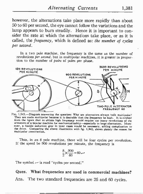
Fin. 1,943.-Diagram answering the question: Why are alternators always built multipolar? They are made multipolar because it is desirable that the frequency be high. It is evident from the figure that to obtain high frequency would require too many revolutions of the armature of a bipolar machine for mechanical safety-especially in large alternators. More- over, a double reduction gear in most cases would be necessary, adding complication to the drive. Comparing the above illustration with fig. 1.942, shows plainly the reason for multipolar construction.
Thus, in an 8 pole machine, there will be four cycles per revolution. If the speed he 900 revolutions per minute, the frequency is
8 ZX
900 60r
The symbol is read "cycles per second."
Ques. What frequencies are used in commercial machines?
Ans. The two standard frequencies are 25 and 60 cycles.
1,382 Alternating Currents
Ques. For what service are these frequencies adapted?
Ans. The 25 cycle frequency is used for conversion to direct current, for alternating current railways, and for machines of large size; the 60 cycle frequency is used for general distribution for lighting and power.
The frequency of 40 cycles, which once was introduced as a compromise
KNOTT BOSTON
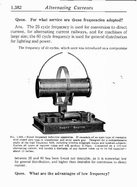
FIG. 1,944.-Knott frequency inductive apparatus. It consists of an open type of resonator with closed core type of transformer and silver spark gap. Designed for a comprehensive study of the high frequency field, including wireless telegraph waves and kindred subjects. Excites all types of vacuum tubes and will produce X -Rays. Connected on a 110 -volt alternating current, will furnish a discharge of any desired value up to its full capacity- about 12 inches.
between 25 and 60 has been found not desirable, as it is somewhat low for general distribution, and higher than desirable for conversion to direct current.
Ques. What are the advantages of low frequency?

Alternating Currents 1,383
Ans. The number of rev- olutions of the rotor is cor- respondingly low; arc lamps can be more readily op- erated; better pressure regu-
É lation; small motors such as fan motors can be operated
1 more easily from the circuit.
Phase.-As applied to an e
° alternating current, phase
E0.5 denotes the angle turned
r through by the generating ele -
á men! reckoned from a given E instant.* Phase is usually c ° measured in degrees from
the initial position of zero generation.
- If in the diagram fig. 1,945, the elementary armature or
s ó loop be the generating element, c and the curve at the right be
the sine curve representing the a current, then the phase of any ó point p, will be the angle0 or
angle moved through from the b, horizontal line, the starting 71 i point. wá
_'- Ques. What is phase dif- ,E,? ference? 1,1 z - .NOTE.-Phase. Another definition:
l ° Any positron on an a.c. or pressure curve ui ° as indicated by sorne reference position. 1 é Usually the phase position is defined by
specifying the number of electrical de - p grees between the phase and the reference
tZ position.
1,384 Alternating Currents
Ans. The angle between the phases of two or more alternat- ing current quantities as measured in degrees.
Ques. What is phase displacement?
Ans. A change of phase of an alternating pressure or current.
Synchronism.-This term may be defined as: the simul- taneous occurrence of any two events. Thus two alternating cur -
ALTERNATOR NO.2
0 180°
qRNATOR N . TO ENGINE
ALTERNATOR NO.I
CHAIN DRIVE
SYNCHRONOUS OPERTION
0o' FOR EQUAL REACTANCES
ALTERNATOR NO.2
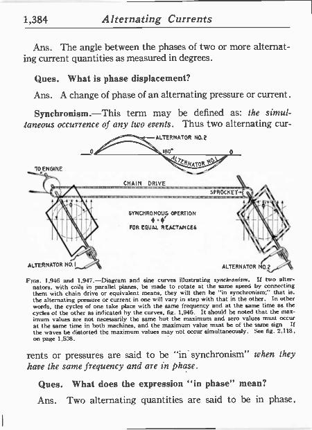
Ftcs. 1,916 and 1,947.-Diagram and sine curves illustrating synchronism. If two alter- nators, with coils in parallel planes, be made to rotate at the same speed by connecting them with chain drive or equivalent means, they will then he "in synchronism;" that is.
the alternating pressure or current in one will vary in step with that in the other. In other words, the cycles of one take place with the same frequency and at the same time as the cycles of the other as indicated by the curves, fig. 1,946. It should be noted that the max- imum values are not necessarily the same but the maximum and zero values must occur at the same time in both machines, and the maximum value must be of the same sign If the waves be distorted the maximum values may not occur simultaneously. See fig. 2,118. on page 1,538.
rents or pressures are said to be "in synchronism" when they have the same frequency and are in phase.
Ques. What does the expression "in phase" mean?
Ans. Two alternating quantities are said to be in phase,
Alternating Currents 1,385
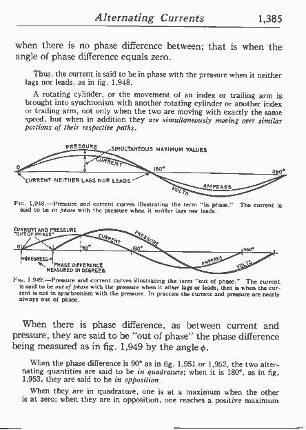
when there is no phase difference between; that is when the angle of phase difference equals zero.
0
Thus, the current is said to he in phase with the pressure when it neither lags nor leads, as in fig. 1,948.
A rotating cylinder, or the movement of an index or trailing arm is brought into synchronism with another rotating cylinder or another index or trailing arm, not only when the two are moving with exactly the same speed, but when in addition they are simultaneously moving over similar portions of their respective paths.
PRESSURE SIMULTANEOUS MAXIMUM VALUES
CURRENT NEITHER LAGS NOR LEADS
180°
T AM PERES
360.
FIG. 1,948.-Pressure and current curves illustrating the term "in phase." The current is said to be in phase with the pressure when it neither lags nor leads.
CURRENT AND PRESSURE -OUT OF PSI ASE'
44 DEGREES
PRASE DIFFERENCE MEASURED IN DEGREES
FIG. 1,949.-Pressure and current curves illustrating the term "out of phase." The current is said to be out of phase with the pressure when it either lags or leads, that is when the cur- rent is not in synchronism with the pressure. In practice the current and pressure are nearly always out of phase.
When there is phase difference, as between current and pressure, they are said to he "out of phase" the phase difference being measured as in fig. 1,949 by the angle 0.
When the phase difference is 90° as in fig. 1,951 or 1,952, the two alter- nating quantities are said to be in quadrature; when it is 180°, as in fig. 1,953, they are said to be in opposition.
When they are in .quadrature, one is at a maximum when the other is at zero; when they are in opposition, one reaches a positive maximum
1,386 Alternating Currents
hJ/4'7 `\\001.4'r IÑDUCTANCE CAUSED BY
,/ aT' \ SYNCHRONISM OF A,y/ iQ \ CURRENT QPRESSURE 01.,
VJ
when the other reaches a negative maximum, being at each instant op- posite in sign.
Ques. What is a departure from synchronism called?
Ans. Loss of synchronism.
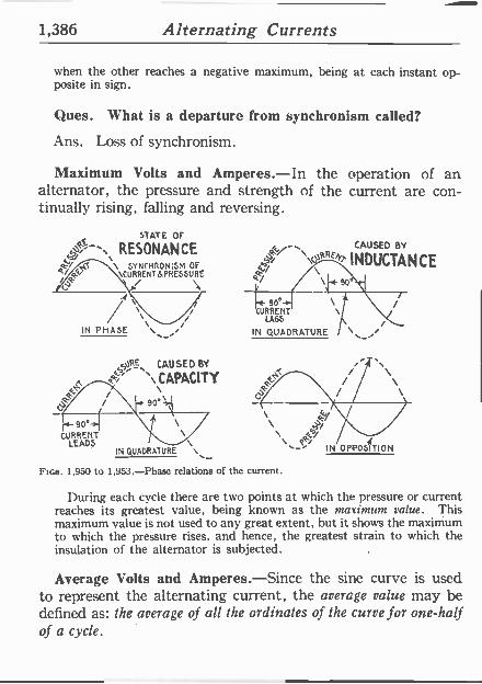
Maximum Volts and Amperes.-In the operation of an alternator, the pressure and strength of the current are con- tinually rising, falling and reversing.
STATE OF
hhJSRESONANCE 4,
ORE, CAUSED BY
\ CAPACITY
Je / I 90°
re -90° CURRENT
LEADS \ IN QUADRATURE \
90°- \ CURRENT \
LAGS
IN QUADRATURE
P
\ J t(,`/
% IN OPPOSITION
Fins. 1,950 to 1,953.-Phase relations of the current.
/'I'\ \ \ \
During each cycle there are two points at which the pressure or current reaches its greatest value, being known as the mari,num value. This maximum value is not used to any great extent, but it shows the maximum to which the pressure rises, and hence, the greatest strain to which the insulation of the alternator is subjected.
Average Volts and Amperes.-Since the sine curve is used to represent the alternating current, the average value may be defined as: the average of all the ordinates of the curve for one-half of a cycle.
Alternating Currents 1,387
Ques. Of what use is the average value?
Ans. It is used in some calculations but, like the maximum value, not very often. The relation between the average and virtual value is of importance as it gives the form factor.
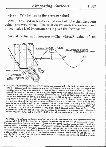
Virtual Volts and Amperes.-The virtual* value of an
1,000,000 LINES OF FORCE
MAXIMUM PRESS U' E. 157 VOLTS
ONE 26 REV, PER SECANTS'A ERASE _ VOLT
AVERAGE PRESSURE
4s 164000.000f
VOLTS
90
RTUAL PRESSURE 1.11 VOLTS AVERAGE ARESSUREI VOLT
360"
FIG. 1,954.-Elementary alternator developing one average volt. If the loop make one revolu- tion per second, and the maximum number of lines of force embraced by the loop in the position shown (the zero position) be denoted by N, then each limb will cut 2N lines per second, because it cuts every line during the right sweep and again during the left sweep. Hence each limb develops an average pressure of 2N units (C.C.S. units), and as both limbs are connected in series, the total pressure is 4N units per revolution. Nos, if the loop make f, revolutions per second instead of only one, then f, times as many lines will be cut per second, and the average pressure will he 4N f units. Since the C.G.S. unit of pres- sure is so extremely small, a much greater practical unit called the volt is used, which is equal to 100 000,000, or 109 C.G.S. units arc employed. I fence average voltage =4Nf =10+. The value of N, in actual machines is very high, being several million lines of force. The illustration shows one set of conditions necessary to generate one average volt. The max- imum pressure developed is 1 _.637 =1.57 volts; virtual pressure =1.57 X.707=1.11 colts.
*NOTE.-"/ adhere to the term virtual, as it was in use before the term efficace which was recommended in 1889 by the Paris Congress to denote the square Toot of mean square value. The corresponding English adjective is efficacious; but some engineers mistranslate it with the word effective. I adhere to the term virtual mainly because the adjective effective is required in its usual meaning in kinematics to represent the resolved part of a force which acts obliquely to the line of motion, the effective force being the whole force multiplied by the cosine of the angle at which it acts with respect to the direction of motion. Some authors use the expres- sion 'R. M. S value' (meaning 'root mean square') to denote the virtual or quadratic mean value."-S. P. Thompson.
1,388 Alternating Currents
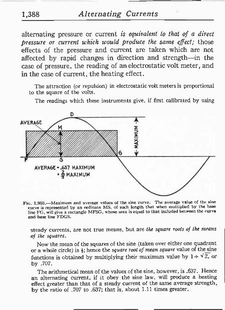
alternating pressure or current is equivalent to that of a direct pressure or current which would produce the same effect; those effects of the pressure and current are taken which are not affected by rapid changes in direction and strength-in the case of pressure, the reading of an electrostatic volt meter, and in the case of current, the heating effect.
The attraction (or repulsion) ín electrostatic volt meters is proportional to the square of the volts.
The readings which these instruments give, if first calibrated by using
AVERAGE s I'ii//i X
5 AVERAGE .637 MAXIMUM
MAXIMUM
FIG. 1,955.-Maximum and average values of the sine curve. The average value of the sine
curve is represented by an ordinate MS, of such length that when multiplied by the base
line FG, will give a rectangle MFSG, whose area is equal to that included between the curve and base line FDGS.
steady currents, are not true means, but are the square roots of the means of the squares.
Now the mean of the squares of the sine (taken over either one quadrant or a whole circle) is 1j; hence the square root of mean square value of the sine
functions is obtained by multiplying their maximt:m value by 1= V 2, or by .707.
The arithmetical mean of the values of the sine, however, is .637. Hence an alternating current, if it obey the sine law, will produce a heating effect greater than that of a steady current of the same average strength, by the ratio of .707 to .637; that is, about 1.11 times greater.
Alternating Currents 1,389
I>lé
1= a< Is
fi -F p
.yvr ü p 151E5'1G@
V r c)
1tl_ áóó - O o
V r! y V
vi
N y 4 r 13 3 C :1 4 C: m N
ú.J ir n
C C N
ó B ñ á+"
r0 tV v C
vió21En N N .ñó
4.531 eu,P:<óVú G7
O 4
O c
C.-?. 0. cc .ºro
., O
1:-da C ` ú 1111É1
V
.`11;1'1 '
C
bcAáUu 3 ñ
Ea:ro3 á 11.-0
¿ 5 q
Ú...ú>iz . f:
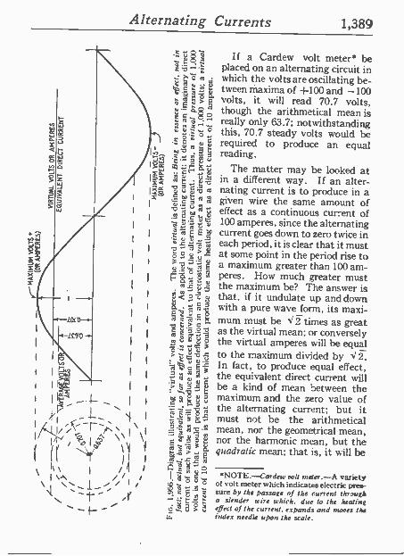
If a Cardew volt meter* be placed on an alternating circuit in which the volts are oscillating be- tween maxima of -1-100 and -100 volts, it will read 70.7 volts, though the arithmetical mean is really only 63.7; notwithstanding this, 70.7 steady volts would be required to produce an equal reading.
The matter may be locked at in a different way. If an alter- nating current is to produce in a given wire the same amount of effect as a continuous current of 100 amperes, since the alternating current goes down to zero twice in each period, it is clear that it must at some point in the period rise to a maximum greater than 100 am- peres. How much greater must the maximum be? The answer is that, if it undulate up and down with a pure wave form, its maxi- mum must be < .1 times as great as the virtual mean; or conversely the virtual amperes will be equal to the maximum divided by J2_ In fact, to produce equal effect, the equivalent direct current will he a kind of mean between the maximum and the zero value of the alternating current; but it must not be the arithmetical mean, nor the geometrical mean, nor the harmonic mean, but the quadratic mean; that is, it will be
*NOTE.--Cardew roll rnster.-A variety of volt meter which indicates electric pres- sure by the passage of the current Eh -rough a slender wire which, due to the heating effect of the current, expands and mores the index needle upon the scale.
1,390 Alternating Currents
the square root of the mean of the squares of all the instantaneous values between zero and maximum.
Effective Volts and Amperes.-Virtual pressure, although already explained, may he further defined as the pressure impressed on a circuit. Now, in nearly all circuits the im- pressed or virtual pressure meets with an opposing pressure due to inductance and hence the effective pressure is something less than the virtual, being defined as that pressure which is
ALTERNATOR
SWITCH
11
4I'
ÍID IÍ, Í'
II II i+
Wlli WII!'
INDUCTANCE COIL
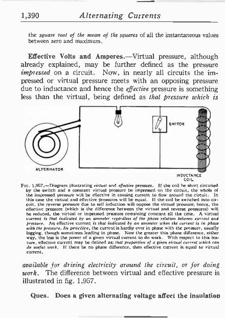
FIG. 1,957.-Diagram illustrating virtual and effective pressure. If the coil he short circuited by the switch and a constant virtual pressure be impressed on the circuit, the whole of the impressed pressure will be effective in causing current to flow around the circuit. In this case the virtual and effective pressures will be equal. If the coil be switched into cir- cuit, the reverse pressure due to self induction will oppose the virtual pressure: hence, the effective pressure (which is the difference between the virtual and reverse pressures) will be reduced, the virtual or impressed pressure remaining constant all the time. A virtual current is that indicated by an ammeter regardless of the phase relation between current and pressure. An effective current is that indicated by an ammeter when the current is in phase with the pressure. /n practice, the current is hardly ever in phase with the pressure, usually lagging, though sometimes leading in phase. Now the greater this phase difference, either way, the less is the power of a given virtual current to do work. With respect to this fea- ture, effective current may be defined as: that proportion of a given virtual current which can do useful work. If there be no phase difference, then effective current is equal to virtual current.
available for driving electricity around the circuit, or for doing work. The difference between virtual and effective pressure is illustrated in fig. 1,957.
Ques. Does a given alternating voltage affect the insulation
Alternating Currents 1,391
of the circuit differently from a direct pressure of the same value?
Ans. It puts more strain on the insulation in the same proportion as the maximum pressure exceeds the virtual pres- sure.
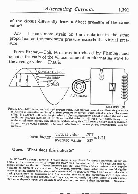
Form Factor.-This term was introduced by Fleming, and denotes the ratio of the virtual value of an alternating wave to the average value. That is
EQUIVALENT D.0
MAXIMUM
VIRTUAL AVERAGE
ALTERNATOR
INDUCTANCE COIL Ftc. 1,958.-Maximum, virtual and average volts. The virtual value of an alternating pressure or current is equivalent to Mai of a direct pressure or current which would produce the same effect. if a Cardew volt meter be placed on an alternating current circuit in which the volts are oscillating between maxima of +100 and -100 volts, it will read 70.7 volts, though the arithmetical mean is really only 63.7; not withstanding this. 70.7 steady volts would be required to produce an equal reading. The word effective is commonly, yet erroneously used for virtual.
form factor = virtual value .707=1.11 average value .637
Ques. What does this indicate?
NOTE-The form factor of a wave shape is significant for certain purposes, as for ex- ample in the determination of hysteresis losses in a transformer, in which case the loss be- comes greater as the form factor becomes less and vice versa under constant r.m.s. supply voltages of different wave shapes. In general. however, form factor has no useful signifi- cance as an indication of the shape of a wave or of its departure from a sine wave. An alter- nating wave may be composed of a fundamental sine wave and harmonics with frequencies that are multiples of the fundamental frequency, consequently the form factor of such a com- plex wave depends upon the amplitude and relative positions of these harmonics.- Hausman.
1,392 Alternating Currents
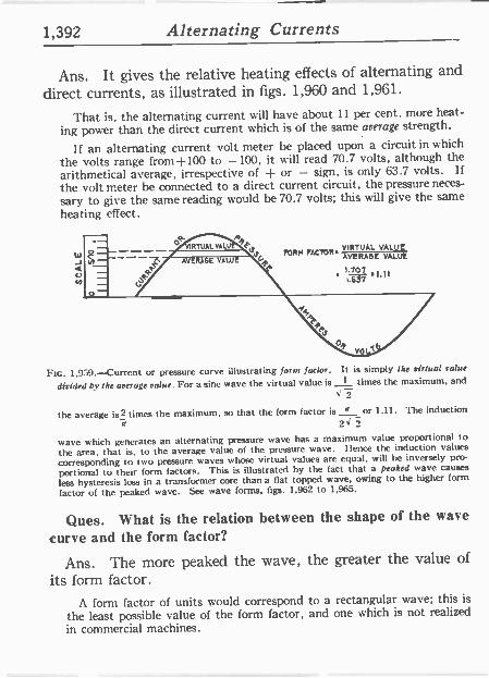
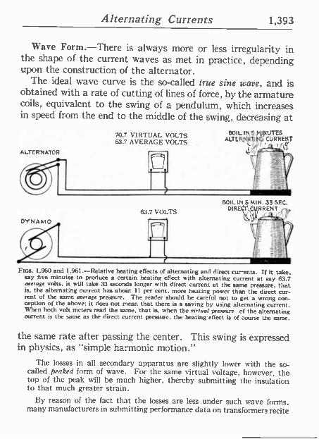
Ans. It gives the relative heating effects of alternating and
direct currents, as illustrated in figs. 1,960 and 1,961.
That is, the alternating current will have about 11 per cent. more heat-
ing power than the direct current which is of the same average strength.
If an alternating current volt meter he placed upon a circuit in which
the volts range from+100 to -100, it will read 70.7 volts, although the arithmetical average, irrespective of + or - sign, is only 63.7 volts. If
the volt meter he connected to a direct current circuit, the pressure neces-
sary to give the same reading would be 70.7 volts; this will give the same heating effect.
FORM FCfbR. VIRTUAL VALUE AVERAGE VALVE
).707 ' 1'.637 ' I.11
Ftc. 1,959.-Current or pressure curve illustrating form factor. It is simply the virtual value
divided by the average value. For a sine wave the virtual value is t times the maximum, and J
the average is times the maximum, so that the form factor is = or 1.11. The induction it 2I
wave which generates an alternating pressure wave has a maximum value proportional to
the area, that is, to the average value of the pressure wave. I fence the induction values
corresponding to two pressure waves whose virtual values are equal. will be inversely pro-
portional to their form factors. This is illustrated by the fact that a peaked wave causes
less hysteresis loss in a transformer core than a flat topped wave, owing to the higher form
factor of the peaked wave. See wave forms, figs. 1,962 to 1,965.
Ques. What is the relation between the shape of the wave
curve and the form factor?
Ans. The more peaked the wave, the greater the value of
its form factor.
A form factor of units would correspond to a rectangular wave; this is
the least possible value of the form factor, and one which is not realized
in commercial machines.
Alternating Currents 1,393
Wave Form.-There is always more or less irregularity in the shape of the current waves as met in practice, depending upon the construction of the alternator.
The ideal wave curve is the so-called true sine wave, and is obtained with a rate of cutting of lines of force, by the armature coils, equivalent to the swing of a pendulum, which increases in speed from the end to the middle of the swing, decreasing at
ALTERNATOR
DYNAMO
70.7 VIRTUAL VOLTS BOIL IN JJJJJJ¡¡¡¡¡¡111111MUTES
ALTER121f(i CURRENT 63.7 AVERAGE VOLTS
63.7 VOLTS
BOIL INS MIN. 33 SEC. DIRE T\CyRRENT e,
Fics. 1,960 and 1,961.-Relative heating effects of alternating and direct cur-ents. If it take, say five minutes to produce a certain heating effect with alternating current at say 63.7 average volts, it will take 33 seconds longer with direct current at the same pressure, that is, the alternating current has about II per cent. more heating power than the direct cur- rent of the same average pressure. The reader should he careful not to get a wrong con- ception of the above: it does not mean that there is a saving by using alternating current. When both volt meters read the same, that is, when the virtual pressure of the alternating current is the same as the direct current pressure, the heating effect is of course the same.
the same rate after passing the center. This swing is expressed in physics, as "simple harmonic motion."
The losses in all secondary apparatus are slightly lower with the so- called peaked form of wave. For the same virtual voltage, however, the top of the peak will be much higher, thereby submitting the insulation to that much greater strain.
By reason of the fact that the losses are less under such wave forms, many manufacturers in submitting performance data on transformers recite
1,394 Alternating Currents
that the figures are for sine wave conditions, stating further that if the
transformers are to be operated in a circuit more peaked than the sine
wave, the losses will be less than shown.
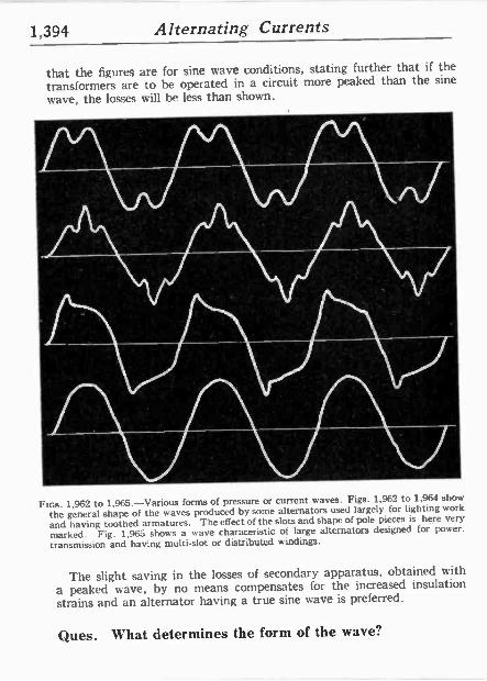
FIGs. 1,962 to 1,965.-Various forms of pressure or current waves. Figs. 1,962 to 1.964 show
the general shape of the waves produced by some alternators used largely for lighting work
and having toothed armatures. The effect of the slots and shape of pole pieces is here very
marked. Fig. 1,965 shows a wave characeristic of large alternators designed for power.
transmission and having multi -slot or distributed windings.
The slight saving in the losses of secondary apparatus, obtained with
a peaked wave, by no means compensates for the increased insulation
strains and an alternator having a true sine wave is preferred.
Ques. What determines the form of the wave?
Alternating Currents 1,395
Ans. 1. The number of coils per phase per pole, 2, shape of pole faces, 3, eddy currents in the pole pieces, and 4, the air gap.
Ques. What are the requirements for proper rate of cutting of the lines of force?
NO.I
NO.2
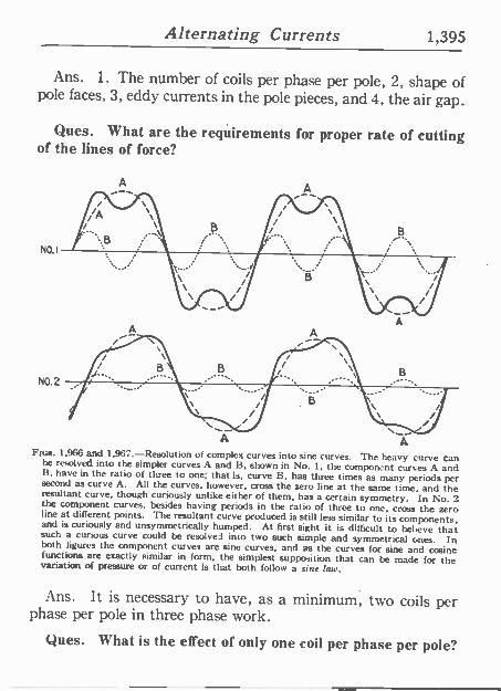
FIGS. 1.966 and 1,967.-Resolution of complex curves into sine curves. The heavy curve can be resolved into the simpler curves A and B. shown in No. 1, the component curves A and B, have in the ratio of three to one; that is, curve B. has three times as many periods per second as curve A. All the curves, however, cross the zero line at the same time, and the resultant curve, though curiously unlike either of them, has a certain symmetry. In No. 2 the component curves, besides having periods in the ratio of three to one, cross the zero line at different points. The resultant curve produced is still less similar to its components. and is curiously and unsymmetrically humped. At first sight it is difficult to believe that such a curious curve could be resolved into two such simple and symmetrical ones. In both figures the component curves are sine curves, and as the curves for sine and cosine functions are exactly similar in form, the simplest supposition that can be made for the variation of pressure or of current is that both follow a sine law.
Ans. It is necessary to have, as a minimum, two coils per phase per pole in three phase work.
Ques. M hat is the effect of only one coil per phase per pole?
1,396 Alternating Currents
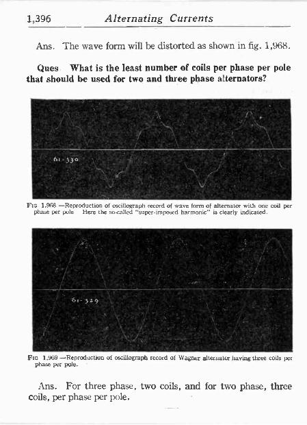
Ans. The wave form will be distorted as shown in fig. 1,968.
Ques: What is the least number of coils per phase per pole that should be used for two and three phase alternators?
Ftc. 1.968 -Reproduction of oscillograph record of wave form of alternator with one coil per phase per pole Here the so-called "super imposed harmonic" is clearly indicated.
9'
ocy..
mt Jl °'&! ' \.
'ym
_ ¢
,X FIG 1.969 -Reproduction of oscillograph record of Wagner alternator having three coils per
phase per pole.
Ans. For three phase, two coils, and for two phase, three coils, per phase per pole.
Alternating Currents 1,397
G °
20 ,44 G0 80 ' R0 140 160 180 200 220 240 260 280 300 323 340
a : ;. . : ..
'VOLTAGE CURVE OF Z000 Kw; 25 CYCLE, 3 PHASE, A0 POLE,_ ALTERNATOR, FULLY LOADED.
º , I
' 3b0
0 20 40 (A 80 100 2 140 1601
NO LOAD VOLTAGE CURVE OF i' Kw, 125 CYCLE , S POLE .
-SINGLE PHASE ALTERNATOR.
"360 t 1 l 1
204 220 240 260 2PC 300 32,0 340 ,
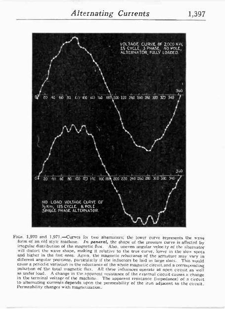
FIGS. 1.970 and 1,971.-Curves for two alternators; the lower curve represents the wave form of an old style machine. In general, the shape of the pressure curve is affected by irregular distribution of the magnetic flux. Also, uneven angular velocity of the alternator will distort the wave shape, making it relative to the true curve, lower in the slow spots and higher in the fast ones. Again, the magnetic reluctance of the armature may vary in different angular positions, particularly if the inductors be laid in large slots. This would cause a periodic variation in the reluctance of the whole magnetic circuit. and a corresponding pulsation of the total magnetic flux. All these influences operate at open circuit as well as under load. A change in the apparent resistance of the external circuit causes a change in the terminal voltage of the machine. The apparent resistance (impedance) of a circuit to alternating currents depends upon the permeability of the iron adjacent to the circuit. Permeability changes with magnetization.
1,398 Alternating Currents
ó
fa" _ _;ce
o-
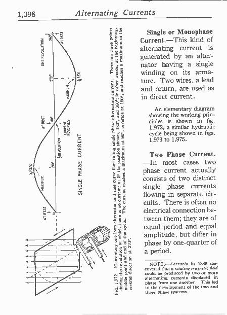
Single or Monophase Current.-This kind of alternating current is generated by an alter- nator having a single winding on its arma- ture. Two wires, a lead and return, are used as in direct current.
An elementary diagram showing the working prin- ciples is shown in fig. 1,972, a similar hydraulic cycle being shown in figs. 1,973 to 1,975.
Two Phase Current. -In most cases two phase current actually consists of two distinct single phase currents flowing in separate cir- cuits. There is often no electrical connection be- tween them; they are of equal period and equal amplitude, but differ in phase by one -quarter of a period.
NOTE.-Ferraris in 1888 dis- covered that a rotaltng magnetic field could be produced by two or more alternating currents displaced in phase from one another. This led to the development of the two and three phase systems.
Alternating Currents 1,399
MAXIMUM VELOCITY
Al REST
CENTRIFU3AL PVMP
STROKE
900
STCM
REVOLUTION
+
I/REVERSES
IB0°
AT REST
SINGLE PHASE ALTERNATING CURRENT
ONE REVOWTIO
AT REST
270°
270°
STRo KE
MAXIMUM VELOCITY REVERSE DIRECTION
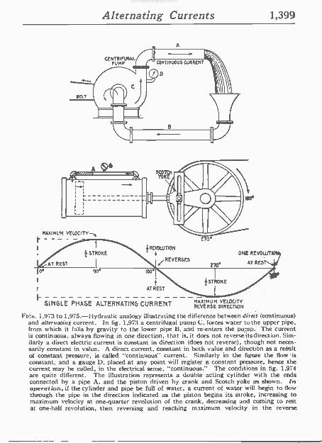
FIGS. 1,973 to 1,975.-Hydraulic analogy illustrating the difference between direct (continuous) and alternating current. In fig. 1,973 a centrifugal pump C, forces water to the upper pipe. from which it falls by gravity to the lower pipe B, and re-enters the pump. The current is continuous, always flowing in one direction, that is, it does not reverseitsdirection. Sim- ilarly a direct electric current is constant in direction (does not reverse), though not neces- sarily constant in value. A direct current, constant in both value and direction as a result of constant pressure, is called "continuous" current. Similarly in the figure the flow -is constant, and a gauge D. placed at any point will register a constant pressures hence the current may be called, in the electrical sense, "continuous." The conditions in fig. 1,974 are quite different. The illustration represents a double acting cylinder with the ends connected by a pipe A, and the piston driven by crank and Scotch yoke as shown. In operation, if the cylinder and pipe be full of water, a current of water will begin to flow through the pipe in the direction indicated as the piston begins its stroke, increasing to maximum velocity at one -quarter revolution of the crank, decreasing and coming to rest at one-half revolution, then reversing and reaching maximum velocity in the reverse
1,400 Alternating Currents
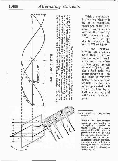
With this phase re- lation one of them will be at a maximum when the other is at zero. Two phase cur- rent is illustrated by sine curves in fig. 1,976, and by hy- draulic analogy in figs. 1,977 to 1,979.
If two identical simple alternators have their armature shafts coupled in such a manner, that when a given armature coil on one is directly un- der a field pole, the corresponding coil on the other is midway between two poles of its field, the two cur- rents generated will differ in phase by a half alternation, and will he two phase cur- rent.
FIGS. 1,973 to 1,975.-Test continued.
direction at three-quarter revolution, and coming to rest again at the end of the return stroke. A pressure gauge at G, will register a pressure which varies with the current. Since the al- ternating electric current undergoes similar changes, the sine curve will apply equally as well to the pump cycle as to the alternating current cycle.
Alternating Currents 1,401
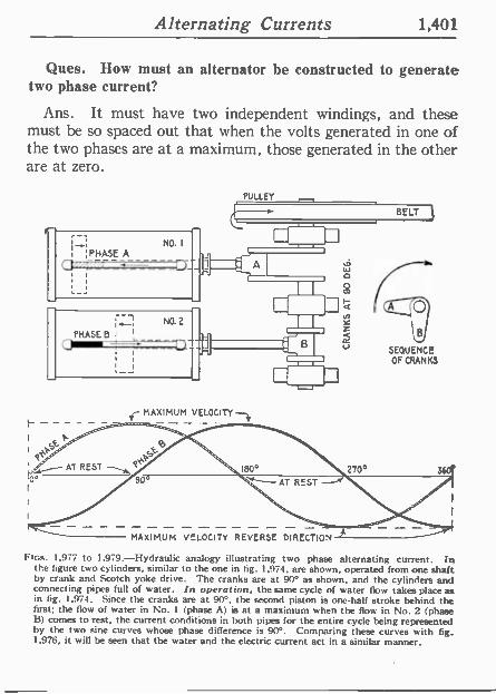
Ques. How must an alternator be constructed to generate two phase current?
Ans. It must have two independent windings, and these must be so spaced out that when the volts generated in one of the two phases are at a maximum, those generated in the other are at zero.
NO. I
I~:PHASE A
(3_7
:
NO.2 ¡I PHASE CPMW-D- 1
i I
L
PULLEY
BELT
1--
] '
ce
MAXIMUM VELOCITY
MAXIMUM VELOCITY REVERSE DIRECTION
SEQUENCE OF CRANKS
FIGS. 1,977 to 1.979.-Hydraulic analogy illustrating two phase alternating current. In the figure two cylinders, similar to the one in fig. 1,974. are shown, operated from one shaft by crank and Scotch yoke drive. The cranks are at 90° as shown, and the cylinders and connecting pipes full of water. In operation. the same cycle of water flow takes place as in fig. 1,974. Since the cranks are at 90°. the second piston is one-half etroke behind the first; the flow of water in No. 1 (phase A) is at a maximum when the flow in No. 2 (phase B) comes to rest, the current conditions in both pipes for the entire cycle being represented by the two sine curves whose phase difference is 90°. Comparing these curves with fig. 1,976, it will be seen that the water and the electric current act in a similar manner.
1,402 Alternating Currents
In other words, the windings, which must be alike, of an equal number of turns, must be displaced along the armature by an angle corresponding to one -quarter of a period, that is, to half the pole pitch.
The windings of the two phases' must, of course, be kept separate, hence the armature will have four terminals, or if it he a revolving arma- ture it will have four collector rings.
As must be evident the phase difference may be of any value between 0° and 360°, but in practice it is almost always made 90°.
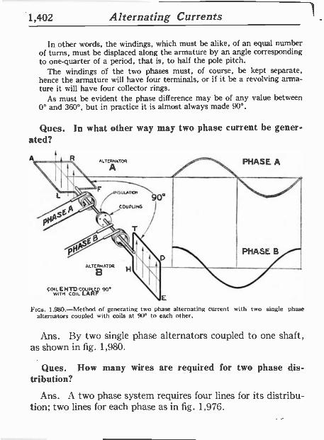
Ques. In what other way may two phase current be gener- ated?
COIL
FIGS. 1.980.-Method of generating two phase alternating current with two single phase alternators coupled with coils at 90° to each other.
Ans. By two single phase alternators coupled to one shaft, as shown in fig. 1,980.
Ques. How many wires are required for two phase dis- tribution?
Ans. A two phase system requires four lines for its distribu- tion; two lines for each phase as in fig. 1,976.
Alternating Currents 1,403
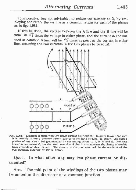
It is possible, but not advisable, to reduce the number to 3, by em- ploying one rather thicker line as a common return for each of the phases as in fig. 1,981.
If this be done, the voltage between the A line and the B line will be equal to <2 times the voltage in either phase, and the current in the line used as common return will be <1 -times as great as the current in either line. assuming the two currents in the two phases to be equal.
Ftc. 1,981.-Diagram of three wire two phase current distribution. In order to save one wire it is possible to use a common return conductor for both circuits, as shown, the dotted portion of one wire 4. being eliminated by connecting across to 1, at M and S. For long lines this is economical, but the interconnection of the circuits increases the chance of trouble from grounds or short circuit. The current in the conductor will be the resultant of the two currents, differing by 90° in phase.
Ques. In what other way may two phase current be dis- tributed?
Ans. The mid point of the windings of the two phases may be united in the alternator at a common junction.
1,404 Alternating Currents
This is equivalent to making the machine into a four phase alternator with half the voltage in each of the four phases, which will then he in successive quadrature with each other.
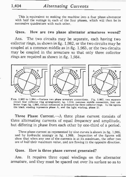
Ques. How are two phase alternator armatures wound?
Ans. The two circuits may be separate, each having two collector rings, as shown in fig. 1,982, or the two circuits may be coupled at a common middle as in fig. 1,983, or the two circuits may be coupled in the armature so that only three collector rings are required as shown in fig. 1,984.
FIGS. 1,982 to 1,984.-Various two phase armature connections. Fig. 1,982, two separate circuit four collector ring arrangement; fig. 1,933, common middle connection, four col- lector rings; fig. 1,984. circuit connected in armature for three collector rings. In the figures the black winding represents phase A, and the light winding, phase B.
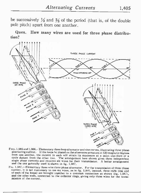
Three Phase Current.-A three phase current consists of three alternating currents of equal frequency and amplitude, but differing in phase from each other by one-third of a period.
Three phase current as represented by sine curves is shown in fig. 1,986, and by hydraulic analogy in fig. 1,988. Inspection of the figures will show that when any one of the currents is at its maximum, the other two are of half their maximum value, and are flowing in the opposite direction.
Ques. How is three phase current generated?
Ans. It requires three equal windings on the alternator armature, and they must he spaced out over its surface so as to
Alternating Currents 1,405
be successively % and % of the period (that is, of the double pole pitch) apart from one another.
Ques. How many wires are used for three phase distribu- tion?
THREE PHASE Six WIRE
THREE PHASE CVRRENT
y^F vF 'flt
THREE PHASE THREE WIRE
Fins. 1.985 and 1,986.- Elementary three loop alternator and sine curves, illustrating three phase alternating current. If the loops be placed on the alternator armature at 120 magnetic degrees from one another, the current in each will attain its maximum at a point one-third of a cycle distant from the other two. The arrangement here shown gives three independent single phase currents and requires six wires for their transmission. A better arrangement and the one generally used is shown in fig. 1,987.
Ftc. 1,987.-Elementary three wire three phase alternator. For the transmission of three phase current, it is not customary to use six wires, as in fig. 1,995, instead, three ends (one end of each of the loops) are brought together to a common connection as shown (fig. 1,987). and the other ends, connected to the collector rings, giving only three wires for the trans- mission of the current.
1,406 Alternating Currents
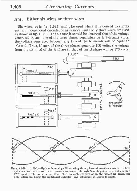
Ans. Either six wires or three wires.
Six wires, as in fig. 1,985, might be used where it is desired to supply entirely independent circuits, or as is more usual only three wires are used as shown in fig. 1,987. In this case it should he observed that if the voltage generated in each one of the three phases separately be E (virtual) volts, the voltage generated between any two of the terminals will be equal to <3XE. Thus, if each of the three phases generate 100 volts, the voltage from the terminal of the A phase to that of the B phase will he 173 volts.
PULLEY
--' N0.1
;PHASE A ,, - _ _-,_zyi- 'G.2,-
,_J
i Trio. 2 [ PHASE B ~'
O1~11 ~J ' 1
l_i
i-'iN0.3 PHASE C , 'l a- 1 4 '
i
i
_ iJ
BELT
--11]
B
w
tÑ
1-- z cr
SEQUENCE OF CRANKS
FIGS. 1,988 to 1,990.-Hydraulic analogy illustrating three phase alternating current. Three cylinders are here shown with pistons connected through Scotch yokes to cranks placed 120° apart. The same action, takes place in each cylinder as in the preceding cases, the only difference being the additional cylinder, and difference in phase relation.
Alternating Currents 1,407
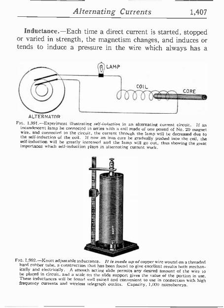
Inductance.-Each time a direct current is started, stopped or varied in strength, the magnetism changes, and induces or tends to induce a pressure in the wire which always has a
QLAMP
COIL
1111-T- CORE
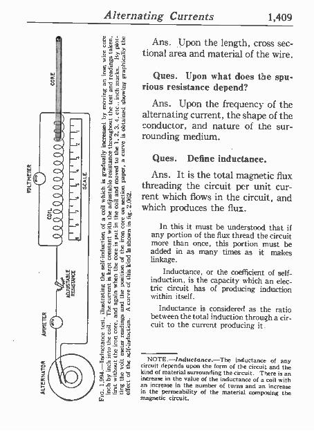
ALTERNATOR FIG. 1.991.-Experiment illustrating self-induction in an alternating current circuit. If an
incandescent lamp he connected in series with a coil made of one pound of No. 20 magnet wire, and connected to the circuit, the current through the lamp will be decreased due to the self-induction of the coil. If now an iron core be gradually pushed into the coil, the self-induction will be greatly increased and the lamp will go out, thus showing the great importance which self-induction plays in alternating current work.
FIG. 1,992-Knott adjustable inductance. It is made up of copper wire wound on a threaded hard rubber tube, a construction that has been found to give excellent results both mechan- ically and electrically. A smooth acting slide permits arty desired amount of the wire to be placed in circuit, and a scale on the slide support gives the value of the portion in use. These inductances will he found well suited and convenient to use in connection with high frequency currents and wireless telegraph outfits. Capacity, 1,000 microhenrys.
1,408 Alternating Currents
direction opposing the pressure which originally produced the current. This self-induced pressure tends to weaken the main cur- rent at the start and prolong it when the circuit is opened.
The expression inductance is frequently used in the same sense as co-
efficient of self-induction, which is a quantity pertaining to an electric cir- cuit depending on its geometrical form and the nature of the surrounding medium.
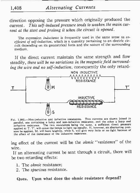
If the direct current maintain the same strength and flow
steadily, there will be no variations in the magnetic field surround- ing the wire and no self-induction, consequently the only retard -
NON INDUCTIVE
T
S
V V
RESISTANCE
I N DUCTI VÉ
RESISTANCE
T'
Ftc. 1,993.-Non-inductive and inductive resistances. Two currents are shown joined in
parallel, one containing a lamp and non -inductive resistance, and the other a lamp and inductive resistance. The two resistances being the same, a sufficient direct pressure applied at T, T', will cause the lamps to light up equally. if, however, an alternating pres-
sure he applied, Al, will burn brightly, while S, will give very little or no light because of
the effect of the inductance of the inductive resistance.
ing effect of the current will be the ohmic "resistance" of the wire. If an alternating current be sent through a circuit, there will
be two retarding effects:
1. The ohmic resistance; 2. The spurious resistance.
Ques. Upon what does the ohmic resistance depend?
Alternating Currents 1,409
Ans. Upon the length, cross sec- tional area and material of the wire.
Ques. Upon what does the spu- rious resistance depend?
Ans. Upon the frequency of the alternating current, the shape of the conductor, and nature of the sur- rounding medium.
Ques. Define inductance.
Ans. It is the total magnetic flux threading the circuit per unit cur- rent which flows in the circuit, and which produces the flux.
In this it must be understood that if any portion of the flux thread the circuit more than once, this portion must be added in as many times as it makes linkage.
Inductance, or the coefficient of self- induction, is the capacity which an elec- tric circuit has of producing induction within itself.
Inductance is considered as the ratio between the total induction through a cir- cuit to the current producing it.
NOTE. Inductance.-The inductance of any circuit depends upon the form of the circuit and the kind of material surrounding the circuit. There is an increase in the value of the inductance of a coil with an increase in the number of turns and an increase in the permeability of the material composing the magnetic circuit.
1,410 Alternating Currents
Ques. What is the unit of inductance?
Ans. The henry.
Ques. Define the henry.
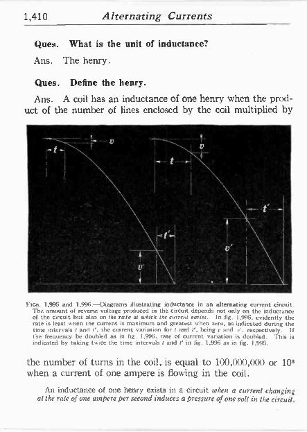
Ans. A coil has an inductance of one henry when the prod- uct of the number of lines enclosed by the coil multiplied by
FIGS. 1,995 and 1,996.-Diagrams illustrating inductance in an alternating current circuit. The amount of reverse voltage produced in the circuit depends not only on the inductance of the circuit but also on the rate al which the current varies. In fig. 1,995, evidently the rate is least when the current is maximum and greatest when zero. as indicated during the time intervals f and f'. the current variation for and t', being a and e'. respectively. If the frequency be doubled as in fig. 1,996. rate of current variation is doubled. This is indicated by taking twice the time intervals t and t' in fig. 1.996 as in fig. 1,995.
the number of turns in the coil, is equal to 100,000,000 or 108 when a current of one ampere is flowing in the coil.
An inductance of one henry exists in a circuit when a current changing at the rate of one ampere per second induces a pressure of one volt in the circuit.
Alternating Currents 1,411
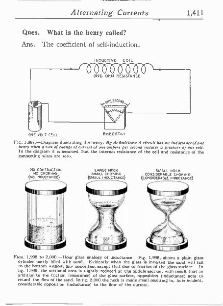
Ques. What is the henry called?
Ans. The coefficient of self-induction.
ONE VOLT CELL
INDUCTIVE COIL
RMEOSTAT
Fro. 1,997.-Diagram illustrating the henry. fly definition: A circuit has an inductanceof one henry when a rate of change of Current of one ampere per second induces a pressure of one roll. In the diagram it is assumed that the internal resistance of the cell and resistance of the connecting wires are zero.
NO CONTRACTION NO CHOKING
(No INDUCTANCE),
LARGE NECH SMALL CHOKING
(SMALL INDUCTANCE)
SMALL NECK CONSIDERABLE CHOKING
(CONSIDERABLE INDUCTANCE)
FtGs. 1,998 to 2,000.-Hour glass analogy of inductance. Fig. 1,998, shows a plain glass cylinder partly filled with sand. Evidently when the glass is inverted the sand will fall to the bottom without any opposition except that due to friction of the glass surface. In fig. 1.999, the sectional area is slightly reduced at the middle section. with result that in addition to the friction (resistance) of the glass surface, opposition (inductance) acts to retard the flow of the sand. In fig. 2,000 the neck is made small resulting in, as is evident. considerable opposition (inductance) to the flow of the current.
1,412 Alternating Currents
or
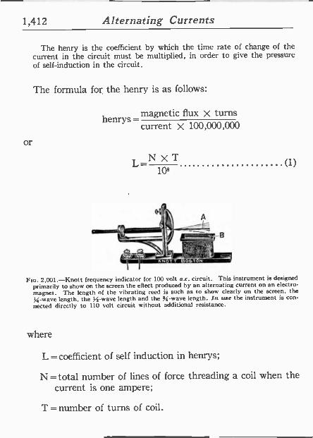
The henry is the coefficient by which the time rate of change of the current in the circuit must be multiplied, in order to give the pressure of self-induction in the circuit.
The formula for the henry is as follows:
henrys-magnetic flux x turns current X 100,000,000
L_N X T 108
41:?. `u<r-
(1)
FIG. 2,001.-Knott frequency indicator for 100 volt a.c. circuit. This instrument is designed primarily to show on the screen the effect produced by an alternating current on an electro- magnet. The length of the vibrating reed is such as to show clearly on the screen, the
.4 wave length, the 1 -1 -wave length and the 35 -wave length. In uae the instrument is con- nected directly to 110 volt circuit without additional resistance.
where
L =coefficient of self induction in henrys;
N = total number of lines of force threading a coil when the current is one ampere;
T = number of turns of coil.
Alternating Currents 1,413
If a coil had a coefficient of self-induction of one henry, it would mean that if the coil had one turn, one ampere would set up 100,000,000, or 108, lines through it.
INDUCTIVE COIL WITH AIR CORE
Imormi ail-- isr
INDUCTIVE COIL WITH IRON CORE
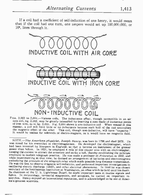
NON- INDUCTIVE COIL Fws. 2,002 to 2,004.-Various coils. The inductance effect, though perceptible in an air
core coil, fig. 2,012, may be greatly intensified by inserting a core made of numerous pieces of iron wire, as in fig. 2.003. Fig. 2,001 shows a non -inductive coil When wound in this manner, a coil will have little or no inductance because each half of the coil neutralizes the magnetic effect of the other This coil, though non -inductive, will have "capacity." It would be useless for solenoids or electro -magnets, as it would have no magnetic field.
NOTE.-The American physicist, Joseph Henry, was born in 1798 and died 1878. He was noted for his researches in electromagnetism. He developed the electromagnet, which had been invented by Sturgeon in England, so that it became an instrument of fat greater power than before. In 1831, he employed a mile of fine copper wire with an electromagnet, causing the current to attract the armature and strike a bell, thereby establishing the principle employed in modern telegraph practice. 1 -le was made a professor at Princeton in 1832, and while experimenting at that time, he devised an arrangement of batteries and electromagnets embodying the principle of the telegraph relay which made possible long distance transmission. He was the first to observe magnetic self-induction, and performed important investigations in oscillating electric discharge (1842), and other electrical phenomena. In 1846 he was chosen secretary of the Smithsonian Institution at Washington, an office which he held until his death. As chairman of the U. S. Lighthouse Board, he made important tests in marine signals and lights. In meteorology, terrestrial magnetism, and acoustics, he carried on important re- searches. Henry enjoyed an international reputation, and is acknowledged to be one of Amer- ica's greatest scientists.
1,414 Alternating Currents
The henry is too large a unit for use in practical computa- tions, which involves that the millihenry, or henry, is the accepted unit.
In pole suspended lines the inductance varies as the metallic resistance,
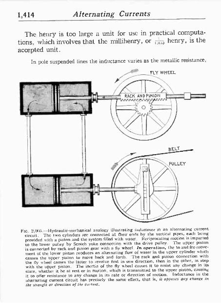
FIG. 2.005.-Hydraulic-mechanical analogy illustrating inductance in an alternating current circuit. The two cylinders are connected at their ends by the vertical pipes, each being
provided with a piston and the system filled with water. Reciprocating motion is imparted
to the lower pulley by Scotch yoke connection with the drive pulley. The upper piston
is connected by rack and pinion gear with a fly wheel. In operation, the to and fro move-
ment of the lower piston produces an alternating flow of water in the upper cylinder which
causes the upper piston to move back and forth. The rack and pinion connection with the fly wheel causes the latter to revolve first in one direction, then in the other, in step with the upper piston. The inertia of the fly wheel causes it to resist any change in its state, whether it be at rest or in motion, which is transmitted to the upper piston, causing
it to offer resistance to any change in its rate or direction of motion. Inductance in the
alternating current circuit has precisely the same effect, that is, it opposes any change in the strength or direction of the current.
Alternating Currents 1,415
the distance between the wires on the cross arm and the number of cycles per second, as indicated by accepted tables. Thus, for one mile of No. 8 B. & S. copper wire, with a resistance of 3,406 ohms, the coefficient of self-induction with 6 inches between centers is .00153, and, with 12 inches, .00175.
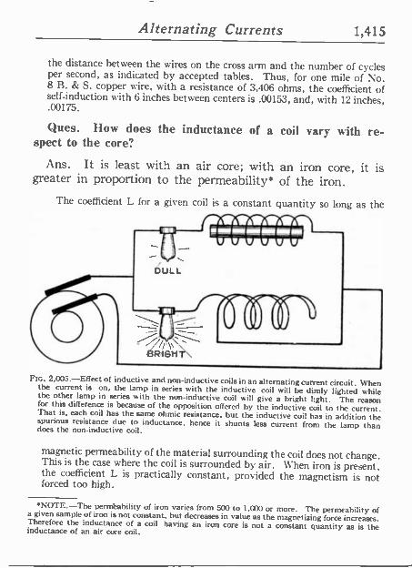
Ques. How does the inductance of a coil vary with re- spect to the core?
Ans. It is least with an air core; with an iron core, it is greater in proportion to the permeability* of the iron.
The coefficient L for a given coil is a constant quantity so long as the
FIG. 2,003.-Effect of inductive and non -inductive coils in an alternating current circuit. When the current is on, the lamp in series with the inductive coil will be dimly lighted while the other lamp in series with the non -inductive coil will give a bright light. The reason for this difference is because of the opposition offered by the inductive coil to the current. That is, each coil has the same ohmic resistance, but the inductive coil has in addition the spurious resistance due to inductance, hence it shunts less current from the lamp than does the non -inductive coil.
magnetic permeability of the material surrounding the coil does not change. This is the case where the coil is surrounded by air. When iron is present, the coefficient L is practically constant, provided the magnetism is not forced too high.
4NOTE.-The permeability of iron varies from 500 to 1,000 or more. The permeability of a given sample of iron is not constant. but decreases in value as the magnetizing force increases. Therefore the inductance of a coil having an iron core is not a constant quantity as is the inductance of an air core coil.
1,416 Alternating Currents
In most cases arising in practice, the coefficient L, may be considered
to be a constant quantity, just as the resistance R, is usually considered
constant. The coefficient L, of a coil or circuit is often spoken of as its
inductance.
Ques. Why is the iron core of an inductive coil made
with a number of small wires instead of one large rod?
Ans. It is laminated in order to reduce eddy currents and
consequent loss of energy, and to prevent excessive heating of
the core.
.3 TURNS 1
A =~ INDUCTANCE I v O.
I HENRY o `
i' SQUARE OF TURNS = 3X3=9 , .
6 TURNS >3;i;i;i; B- ===_ z
.
SQUARE OF TURNS =6X6=36
-
I RATIO OF INCREASE' B TURNSZ=A`TURNS2 =36=9 =4, INDUCTANCE COIL B = iNDUCTA14CE COIL A X RATIO = I X 4 = 4 HENRYS
'
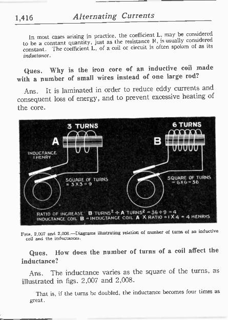
Fos. 2,007 and 2,008.-Diagrams illustrating relation of number of turns of an inductive
coil and the inductances.
Ques. How does the number of turns of a coil affect the
inductance?
Ans. The inductance varies as the square of the turns, as
illustrated ín figs. 2,007 and 2,008.
That is, if the turns he doubled, the inductance becomes four times as
great.
Alternating Currents 1,417
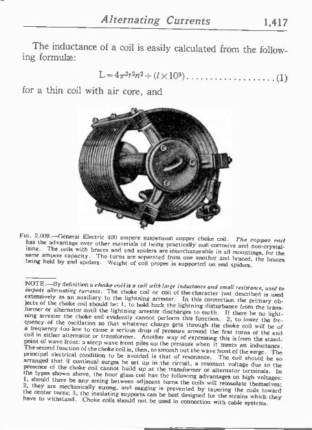
The inductance of a coil is easily calculated from the follow- ing formulae:
L=47r2r2n2_ (1X 10⁹)
for a thin coil with air core, and
as.. FIG. 2.009. --General Electric 400 ampere suspension copper choke coil. The copper coil has the advantage over other materials of being practically non -corrosive and non -crystal- izing. The coils with braces and end spiders are interchangeable in all mountings, for the same ampere capacity. The turns are separated from one another and braced; the braces being held by end spiders. Weight of coil proper is supported on end spiders.
(1)
NOTE.-By definition a choke colt is a coil with large inductance and small resistance, used to impede alternating currents. The choke coil or coil of the character just described is used extensively as an auxiliary to the lightning arrester. In this connection the pri-nary ob- jects of the choke coil should be: 1, to hold back the lightning disturbance from the trans- former or alternator until the lightning arrester discharges to earth. If there be no light- ning arrester the choke coil evidently cannot perform this function. 2, to lower the fre- quency of the oscillation so that whatever charge gets through the choke coil will be of a frequency too low to cause a serious drop of pressure around the first turns of the end coil in either alternator or transformer. Another way of expressing this is from the stand- point of wave front: a steep wave front piles up the pressure when it meets an inductance. The second function of the choke coil is. then, to smooth out the wave front of the surge. The principal electrical condition to be avoided is that of resonance. The coil should be so arranged that if continual surges be set up in the circuit, a resonant voltage due to the presence of the choke coil cannot build up at the transformer or alternator terminals. In the types shown above, the hour glass coil has the following advantages on high voltages: 1. should there he any arcing between adjacent turns the coils will reinsulate themselves; 2, they are mechanically strong, and sagging is prevented by tapering the coils toward the center turns; 3, the insulating supports can be best designed for the strains which they have to withstand. Choke coils should not be used in connection with cable systems.
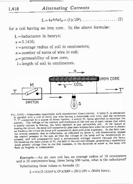
1,418 Alternating Currents
L=47.2721/21,± (1 X 10⁹) (2)
for a coil having an iron core. In the above formulae:
L = inductance in henrys;
,r =3.1416; r = average radius of coil in centimeters;
n= number of turns of wire in coil;
12= permeability of iron core;
1=length of coil in centimeters. ª aoaQo = - IRON CORE
M b COIL
SWITCH S
FIG. 2,010.-Inductance experiment with intermittent direct current. A lamp S, is connected
in parallel with a coil of fairly fine wire having a removable iron core, and the terminals
T, T', connected to a source of direct current, a switch M, being provided to interrupt the
current. The voltage of the current and resistance of the coil are of such values that when
a steady current is flowing, the lamp filament is just perceptibly red. At the instant of
making the circuit, the lamp will momentarily glow more brightlythan when the current is steady;
on breaking the circuit the lamp will momentarily flash with great brightness. In the first case,
the reverse pressure, due to inductance, as indicated by arrow b, will momentarily oppose
the normal pressure in the coil, so that the voltage at the lamp will be momentarily in-
creased, and will consequently send a momentarily stronger current through the lamp.
On breaking the main circuit at NI, the field of the coil will collapse. generating a momentary
much greater voltage than in the first instance, in the direction of arrow a, the lamp will
flash up brightly in consequence.
Example.-An air core coil has an average radius of 10 centimeters
and is 20 centimeters long, there being 500 turns, what is the inductance.'
Substituting these values in formula (1)
L=4X(3.1416)22X10"-X5002=(20X10º) =.00494 henry.
Alternating Currents 1,419
Ques. Is the answer in the above example in the cus- tomary form?
Ans. No; the henry being a very large unit, it is usual to express inductance in thousandths of a henry, that is, in milli - henrys. The answer then would be .04935 x1,000 =49.35 milli -henrys.
Example.-An air core coil has an inductance of 50 milli -henrys; if an iron core, having a permeability of 600 be inserted, what is the inductance."
The inductance of the air core coil will be multiplied by the permeability of the iron; the inductance then is increased to
50X600=30,000 milli -henrys, or 30 henrys.
Ohmic Value of Inductance.-The rate of change of an al- ternating current at any point expressed in degrees is equal to the product of 2 7r multiplied by the frequency, the maximum current, and the cosine of the angle of position O; that is (using symbols)
rate of change =2 7r f I m.x cos O.
The numerical value of the rate of change is independent of its positive or negative sign, so that the sign of the cos is disregarded.
The period of greatest rate of change is that at which cos has the greatest value, and the maximum value of a cosine is when the arc has a value of zero degrees or of 180 degrees, its value corresponding, being 1. (See fig. 2,074, page 1,464.)
The pressure due to inductance is equal to the product of the rate of change by the inductance; that is, calling the inductance L, the pressure due to it at the point of maximum value or
Em.=2 7rf Im<XL (1)
Now by Ohm's law
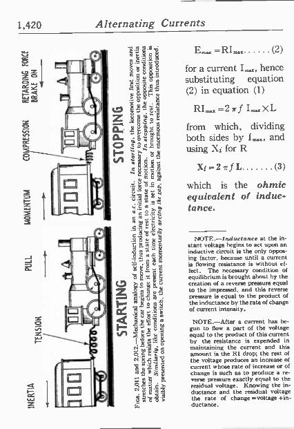
1,420 Alternating Currents
Em,x =RI- (2)
for a current hence substituting equation (2) in equation (1)
RI- =2 it f from which, dividing both sides by I 5, and using Xi for R
Xi=211fL (3)
which is the ohmic equivalent of induc- tance.
NOTE.-Inductance at the in- stant voltage begins to act upon an inductive circuit is the only oppos- ing factor, because until a current is flowing resistance is without ef- fect. The necessary condition of equilibrium is brought about by the creation of a reverse pressure equal to the impressed, and this reverse pressure is equal to the product of the inductance by the rate of change of current intensity.
NOTE.-After a current has be- gun to flow a part of the voltage equal to the product of this current by the resistance is expended in maintaining the current and this amount is the RI drop; the rest of the voltage produces an increase of current whose rate of increase or of change is such as to produce a re- verse pressure exactly equal to the residual voltage. Knowing the in- ductance and the residual voltage the rate of change =voltage +in- ductance.
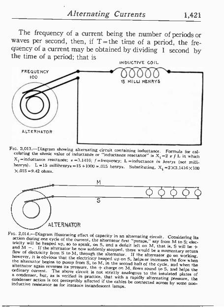
Alternating Currents 1,421
The frequency of a current being the number of periods or waves per second, then, if T=the time of a period, the fre- quency of a current may be obtained by dividing 1 second by the time of a period; that is
FREQUENCY 100
ALTERNATOR
INDUCTIVE COIL
FIG. 2,013.-Diagram showing alternating circuit containing inductance. Formula for cal- culating the ohmic value of inductance or "inductance reactance" is Xt =2 x f L in which Xt =inductance reactance; x =3.1416; f= frequency; L =inductance in henrys (not milli - henrys). L-15 millihenrys=15=1000=.015 henrys. Substituting, Xf=2X3.1416X100 X.015 =9.42 ohms.
M
S
ALTERNATOR
FIG. 2,014.-Diagram illustrating effect of capacity in an alternating circuit. Considering its action during one cycle of the current, the alternator first "pumps." say from M to S; elec- tricity will be heaped up, so to speak, on S. and a deficit left on M, that is, S will be -}- and M - If the alternator be now suddenly stopped, there would be a momentary return flow of electricity from S to M, through the alternator. If the alternator go on working, however, it is obvious that the electricity heaped up on S. helps or increases the flow when the alternator begins to pump from S, to M. in the second halt of the cycle, and when the alternator again reverses its pressure, the 4- charge on M. flows round to S, and helps the ordinary current. The above circuit is not strictly analogous to the insulated plates of a condenser, but, as is verified in practice, that with a rapidly alternating pressure, the condenser action is not perceptibly affected if the cables be connected across by some non - inductive resistance as for instance incandescent lamps.
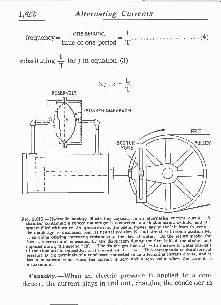
1,422 Alternating Currents
frequency one second 1
time of one period T
substituting 1 - for f in equation (3)
RESERVOIR
r-r
S 4N
II
M
Xi = 2 r T
-RUBBER DIAPHRAGM
r-1
- ----- I
I f
i
.._J
SCOTCH YOKE.
(111 o O
BELT
(4)
PULLEY
FIG. 2,015.-Hydraulic analogy illustrating capacity in an alternating current circuit. A
chamber containing a rubber diaphragm is connected to a double acting cylinder and the system filled with water. In opera( ion, as the piston moves, say to the left from the center, the diaphragm is displaced from its neutral position N, and stretched to some position M, in so doing offering increasing resistance to the flow of water. On the return stroke the flow is reversed and is assisted by the diaphragm during the first half of the stroke, and opposed during the second half. The diaphragm thus acts with the flow of water one-half of the time and in opposition to it one-half of the time. This corresponds to the electrical pressure at the terminals of a condenser connected in an alternating current circuit, and it has a maximum value when the current is zero and a zero value when the current is
a maximum.
Capacity.-When an electric pressure is applied to a con- denser, the current plays in and out, charging the condenser in
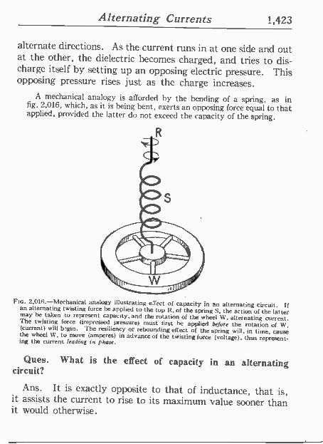
Alternating Currents 1,423
alternate directions. As the current runs in at one side and out at the other, the dielectric becomes charged, and tries to dis- charge itself by setting up an opposing electric pressure. This opposing pressure rises just as the charge increases.
A mechanical analogy is afforded by the bending of a spring, as in fig. 2,016, which, as it is being bent, exerts an opposing force equal to that applied, provided the latter do not exceed the capacity of the spring.
FiG. 2,016.-Mechanical analogy illustrating erect of capacity in an alternating circuit. if an alternating twisting force be applied to the top tt, of the spring S, the action of the latter may be taken to represent capacity, and the rotation of the wheel W, alternating current. The twisting force (impressed pressure) must first be applied before the rotation of W, (current) will b.gin. The resiliency or rebounding effect of the spring will, in time, cause the wheel W, to move (amperes) in advance of the twisting force (voltage), thus represent- ing the current leading in phase.
Ques. What is the effect of capacity in an alternating circuit?
Ans. It is exactly opposite to that of inductance, that is, it assists the current to rise to its maximum value sooner than it would otherwise.
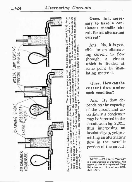
1,424 Alternating Currents
a
Ques. Is it neces- sary to have a con- tinuous metallic cir- cuit for an alternating current?
Ans. No, it ís pos- sible for an alternat- ing current to flow through a circuit which is divided at some point by insu- lating material.
Ques. How can the current flow under such condition?
Ans. Its flow de- pends on the capacity of the circuit and ac- cordingly a condenser may he inserted in the circuit as in fig. 2,021, thus interposing an insulated gap, yet per- mitting an alternating flow in the metallic portion of the circuit.
NOTE.-The terns "farad" is a contraction of Faraday. the name of the distinguished Eng- lish scientist. He was born 1791, died 1867.
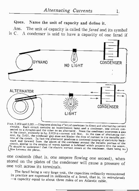
Alternating Currents 1.
Ques. Name the unit of capacity and define it. Ans. The unit of capacity is called the farad and its symbol
is C. A condenser is said to have a capacity of one farad -if
DYNAMO
i'Th CONDENSER
NO LIGHT
ALTER N ATO R
i LIGHT
.__
CONDENSER
l l FIGS. 2,020 and 2,021.-Diagrams showing a^ect of condenser in direct and alternating current circuits. Each circuit contains an incandescent lamp and a condenser, one circuit con- nected to a dynamo and the other to an alternator. Since the condenser interposes a gap in the circuit, evidently in fig. 2,020 no current will flow. In the case of alternating cur- rent, fig. 2,021, the condenser gap does not hinder the flow of current in the metallic por- tion of the circuit. In fact the alternator produces a continual surging of electricity back- ward and forward from the plates of the condenser around the metallic portion of the circuit, similar to the surging of waves against a bulkhead which projects into the ocean. Ct should be understao l that the e.ectric current ceases at the 'condenser, there being nol low between the plates. JJ
one coulomb (that is, one ampere flowing one second), when stored on the plates of the condenser will cause a pressure of one volt across its terminals.
The farad being a very large unit, the capacities ordinarily encountered in practice are expressed in millionths of a farad, that is, in microfarads -a capacity equal to about three miles of an Atlantic cable.
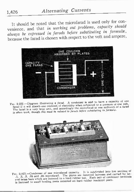
1,426 Alternating Currents
It should be noted that the microfarad is used only for con-
venience, and that in working out problems, capacity should
always be expressed in farads before substituting in formula.,
because the farad ís chosen with respect to the volt and ampere,
ONE COULOMB ABSORBED BY PLATES
CÁPAGI7Y °
i ONE .FARAD -------Y.
Fic. 2,022.-Diagram illustrating a farad. A condenser is said to have a capacity of one
farad if it will absorb one coulomb of electricity when subjected to a pressure of one volt.
The farad is a very large unit, and accordingly the microfarad or one millionth of a farad
is often used, though this must be reduced to farads before substituting in Jonnutw.
- - -.-r . ..----' _' Tp` -__.-. -,
li.EQ9"b MOR r1TmiRY,p
, iSN' A44ER3 YY'VN
V,Mil.nd
LIO Fte. 2,023.-Condenser of one microfarad capacity. It is subdivided into five sections of
.5, .2, .2, .05 and .05 microfarad. The plates are mounted between and carried by lat-
eral brass bars which are fastened to a hard rubber top. Each pair of condenser terminals
is fastened to sruall binding posts mounted on hard rubber insulated posts.
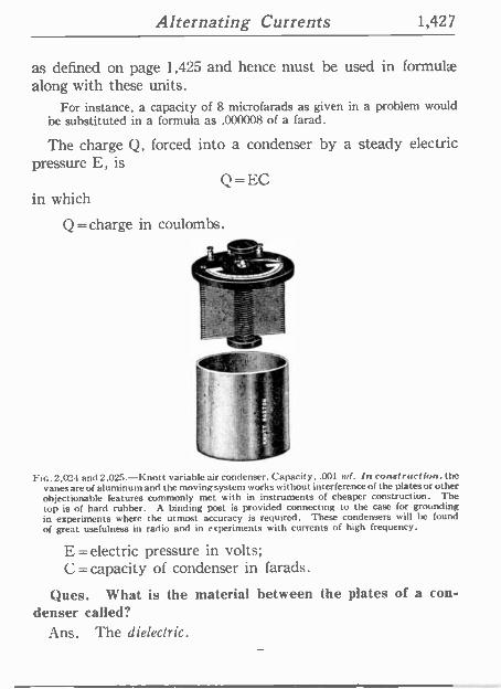
Alternating Currents 1,427
as defined on page 1,425 and hence must be used in formulae along with these units.
For instance, a capacity of 8 microfarads as given in a problem would be substituted in a formula as .000008 of a farad.
The charge Q, forced into a condenser by a steady electric pressure E, is
Q=EC in which
Q = charge in coulombs.
. `f
FIG. 2,024 and 2,025.-Knott variable air condenser. Capacity, .001 mf. In construction. the vanes are of aluminum and the moving system works without interference of the plates or other objectionable features commonly met with in instruments of cheaper construction. The top is of hard rubber. A binding post is provided connecting to the case for grounding in experiments where the utmost accuracy is required. These condensers will be found of great usefulness in radio and in experiments with currents of high frequency.
E =electric pressure in volts; C = capacity of condenser in farads.
flues. What is the material between the plates of a con- denser called?
Ans. The dielectric.
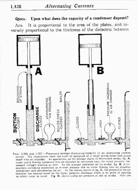
1,428 Alternating Currents
Ques. Upon what does the capacity of a condenser depend?
Ans. It is proportional to the area of the plates, and in- versely proportional to the thickness of the dielectric between
nos. 2,026 and 2,027.-Pneumatic analogy illustrating capacity in an alternating current circuit. The illustrations show the cycle of operation of a single acting boiler feed pump fitted with air chamber. In operation, as the plunger starts its downward stroke. fig. A, water starts flowing (amperes) into air chamber at maximum rate, the water pressure (im- pressed voltage) starting at zero. As the plunger continues on its stroke, fig. B, it en-
counters increasing opposition or reverse pressure due to water flowing into air chamber (condenser) and compressing the air. At the instant shown in fig. C, the pressure in the air chamber has become equal to the boiler pressure; discharge check is on point of opening to admit water to boiler. Fig. D, shows excess air pressure at end of stroke. Here the
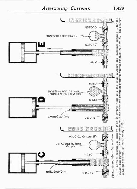
Alternating Currents 1,429
W 3anSS3ad a31109 iv alV
'1 !I'I¡I'lllll'1111 11111'111.11¡It11i11111' i I,iII
« ó II
o c 11'0 `A
1¡ aF ¡,I
II: d W
o3So10 r ," -o
035010-
1 11 n
ii; Inilplk ;
IJ3d0
1, 1IIIiIIlÍl1'I illÍlÍllIl'IIIIIIIiI4il11111j ¡Ijll!I1¡II I .
.3t1nSS3ad a31109 NVHl 133H91H 3a11S53ad tin/
3NOa15 3o OW
N3á0
lilil, II
{ N3d0
111I
Ili
I.
.0141.111.1.11.1111~1...5111.1./...
In¡IIllylyl II
035010
I Ihllll'I 11;111 IIIIIII;Iq9il 1,1111.1Í I I I lI!,I1
hr,
N3d0 OL 9NIlaV15
32inss3ad a311o9 LV t31/
N3d0 . ^
N0I1150d QIIN
- .
.IdI'I LILII
IIIII lip h11,1' III Illlnll4d
035010 lllll' 1
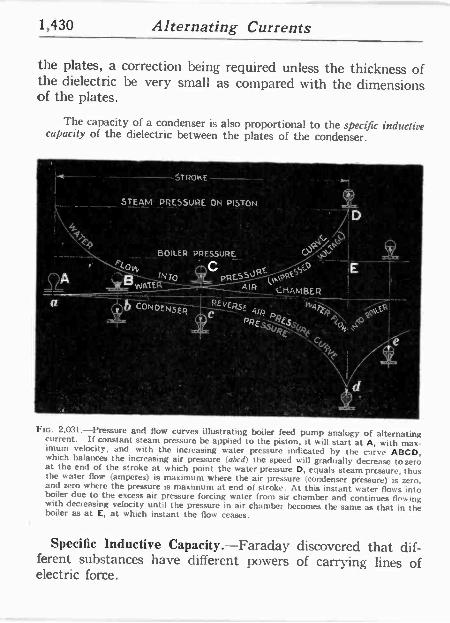
1,430 Alternating Currents
D t. LJP, BOILER PRESSURE atip 2?.
t0`" fNTO pRESSUaEkttiEyScO
!E WATER AIR CHAMBER
the plates, a correction being required unless the thickness of the dielectric be very small as compared with the dimensions of the plates.
The capacity of a condenser is also proportional to the specific inductive capacity of the dielectric between the plates of the condenser.
STROKE
i STEAM PRESSURE ON PISTON
sz.A
a 10 CONDENSE FEvCRsF 4t . wgrfi ! 14u R C R p':. t pREsó qÉ sVqF
(V , .
. C<, 4G f,
Ptc. 2,031.-Pressure and flow curves illustrating boiler feed pump analogy of alternating current. If constant steam pressure be applied to the piston, it will start at A, with max- imum velocity, and with the increasing water pressure indicated by the curve ABCD, which balances the increasing air pressure (abed) the speed will gradually decrease tozero at the end of the stroke at which point the water pressure D, equals steam pressure, thus the water flow (amperes) is maximum where the air pressure (condenser pressure) is zero. and zero where the pressure is maximum at end of stroke. At this instant water flows into boiler due to the excess air pressure forcing water from air chamber and continues fle'wing with decreasing velocity until the pressure in air chamber becomes the same as that in the boiler as at E, at which instant the flow ceases.
Specific Inductive Capacity.-Faraday discovered that dif- ferent substances have different powers of carrying lines of electric force.
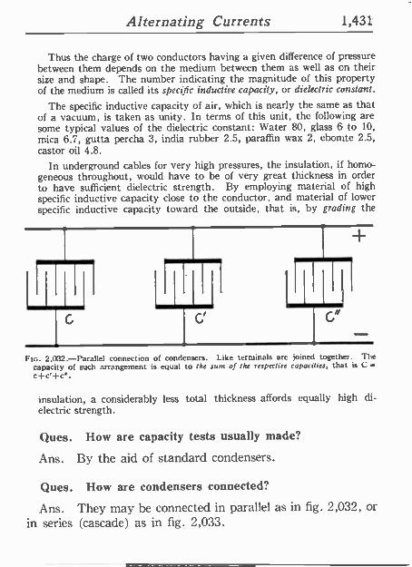
Alternating Currents 1,431
Thus the charge of two conductors having a given difference of pressure between them depends on the medium between them as well as on their size and shape. The number indicating the magnitude of this property of the medium is called its specific inductive capacity, or dielectric constant.
The specific inductive capacity of air, which is nearly the same as that of a vacuum, is taken as unity. In terms of this unit, the following are some typical values of the dielectric constant: Water 80, glass 6 to 10, mica 6.7, gutta percha 3, india rubber 2.5, paraffin wax 2, ebon:te 2.5, castor oil 4.8.
In underground cables for very high pressures, the insulation, if homo- geneous throughout, would have to be of very great thickness in order to have sufficient dielectric strength. By employing material of high specific inductive capacity close to the conductor, and material of lower specific inductive capacity toward the outside, that is, by grading the
Ci
FIG. 2,032.-Parallel connection of condensers. Like terminals are joined together. The capacity of such arrangement is equal to the sum of the respective capacities, that is C =
etc'+c".
insulation, a considerably less total thickness affords equally high di- electric strength.
Ques. How are capacity tests usually made?
Ans. By the aid of standard condensers.
Ques. How are condensers connected?
Ans. They may be connected in parallel as in fig. 2,032, or in series (cascade) as in fig. 2,033.
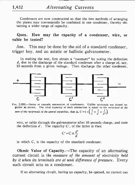
1,432 Alternating Currents
Condensers are now constructed so that the two methods of arranging the plates may conveniently be combined in one condenser, thereby ob- taining a wider range of capacity.
Ques. How may the capacity of a condenser, wire, or cable be tested?
Ans. This may be done by the aid of a standard condenser, trigger key, and an astatic or ballistic galvanometer.
In making the test, first obtain a "constant" by noting the deflection d, due to the discharge of the standard condenser after a chargé of, say, 10 seconds from a given voltage. Then discharge the other condenser,
G
Fte. 2,033.-Series or cascade connection of condensers. Unlike terminals are joined to- gether as shown. The total capacity of such connection is equal to the reciprocal of the
1 1 l sure of the reciprocals of the several capacities, that is, C =1÷( -+ -+ -
c c' c"
wire, or cable through the galvanometer after 10 seconds charge, and note the deflection d'. The capacity C', of the latter is then
C'=CX- d
in which C, is the capacity of the standard condenser.
Ohmic Value of Capacity.-The capacity of an alternating current circuit is the measure of the amount of electricity held by it when its terminals are at unit difference of pressure. Every such circuit acts as a condenser.
If an alternating circuit, having no capacity, he opened, no current can
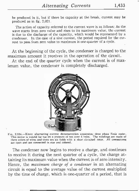
Alternating Currents 1,433
be produced in it, but if there he capacity at the break, current may be produced as in fig. 2,021.
The action of capacity referred to the current wave is as follows: As the wave starts from zero value and rises to its maximum value, the current is due to the discharge of the capacity, which would be represented by a condenser. In the case of a sine current, the period required for the cur- rent to pass from zero value to maximum is one -quarter of a cycle.
At the beginning of the cycle, the condenser is charged to the maximum amount it receives in the operation of the circuit.
At the end of the quarter cycle when the current is of max- imum value, the condenser is completely discharged.
Fio. 2,034.-Knott alternating current demonstration apparatus; three phase Testa maim. This motor is wound for use on a pressure of not over 4 volts. The windings are made of three colors of wires and there are six fields with a short circuited rotor. All connections are open and are connected in star and colored.
The condenser now begins to receive a charge, and continues to receive it during the next quarter of a cycle, the charge at- taining its maximum value when the current is of zero intensity. Hence, the maximum charge of a condenser in an alternating circuit is equal to the average value of the current multiplied by the time of charge, which is one -quarter of a period, that is
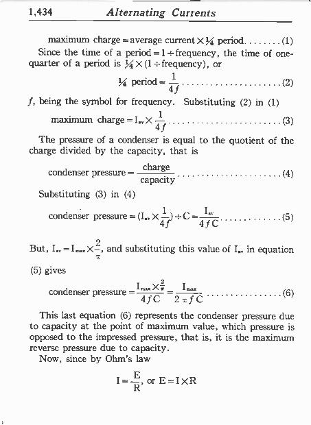
1,434 Alternating Currents
maximum charge =average current X % period (1) Since the time of a period =1= frequency, the time of one -
quarter of a period is % x (1+ frequency), or
Period = (2)
f, being the symbol for frequency. Substituting (2) in (1)
maximum charge =I., x (3)
The pressure of a condenser is equal to the quotient of the charge divided by the capacity, that is
condenser pressure - charge capacity
Substituting (3) in (4)
condenser pressure = (I, X ) : C - f C (5)
But, I..= I-. X , and substituting this value of Ia in equation
(5) gives
mX I,,,. condenser pressure = (6) 4 f C 271fC
This last equation (6) represents the condenser pressure due to capacity at the point of maximum value, which pressure is opposed to the impressed pressure, that is, it is the maximum reverse pressure due to capacity.
Now, since by Ohm's law
I= ?, or E=IXR
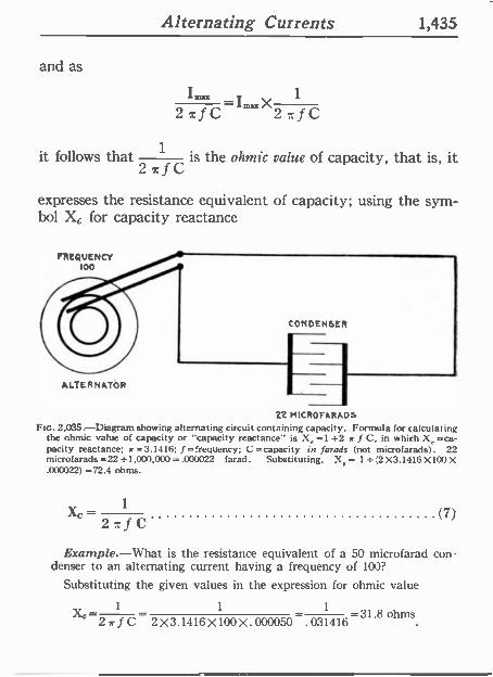
Alternating Currents 1,435
and as
1 2afC 27:fC
it follows that 1 is the ohmic value of capacity, that is, it 2,rfC
expresses the resistance equivalent of capacity; using the sym- bol X, for capacity reactance
CONDENSER
ALTERNATOR
22 MICROFARADS
Ftc. 2,035.-Diagram showing alternating circuit containing capacity. Formula for calculating the ohmic value of capacity or "capacity reactance" is X, =1 +2 c f C, in which X, =ca- pacity reactance; c =3.1416; f =frequency; C =capacity in farads (not microfarads). 22 microfarads =22+1,000,000=.000022 farad. Substituting. X,= 1_(2X3.1416X100X .000022) =72.4 ohms.
1 XC
2 w f C (7)
Example.-What is the resistance equivalent of a 50 microfarad con denser to an alternating current having a frequency of 100?
Substituting the given values in the expression for ohmic value
1 1 1
X` 2 sr f C 2 X 3.1416 X 100 X .000050 .031416 -31.8 ohms
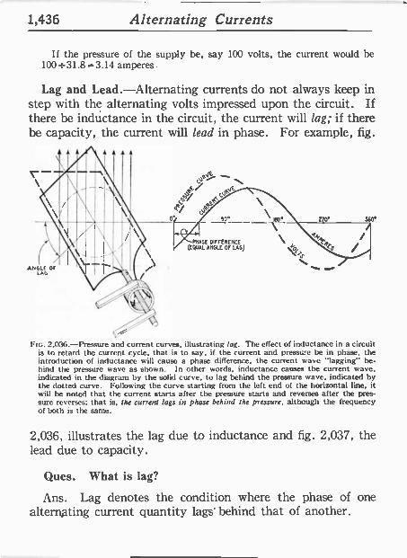
1,436 Alternating Currents
If the pressure of the supply be, say 100 volts, the current would be 100=31.8=3.14 amperes.
Lag and Lead.-Alternating currents do not always keep in step with the alternating volts impressed upon the circuit. If there be inductance in the circuit, the current will lag; if there be capacity, the current will lead in phase. For example, fig.
,P - 1/
c,yhJ Q \ 4 f elks -
0° ___12°\ IBD° \ PMnSE DIFFERENCE \
(EQUAL ANGLE OF LAG) .12:i.
N.. ANGLE Or
LaG
o'
FIG. 2,036.-Pressure and current curves, illustrating lag. The effect of inductance in a circuit is to retard the current cycle, that is to say, if the current and pressure be in phase, the introduction of inductance will cause a phase difference, the current wave "lagging" be- hind the pressure wave as shown. In other words, inductance causes the current wave, indicated in the diagram by the solid curve, to lag behind the pressure wave. indicated by the dotted curve. Following the curve starting from the left end of the horizontal line, it will be noted that the current starts after the pressure starts and reverses after the pres- sure reverses; that is, the current lags in phase behind the pressure, although the frequency of both is the same.
2,036, illustrates the lag due to inductance and fig. 2,037, the lead due to capacity.
Ques. What is lag?
Ans. Lag denotes the condition where the phase of one alternating current quantity lags' behind that of another.
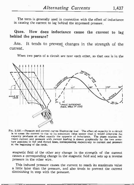
Alternating Currents 1,437
The term is generally used in connection with the effect of inductance in causing the current to lag behind the impressed pressure.
Ques. How does inductance cause the current to lag behind the pressure?
Ans. It tends to prevent changes in the strength of the current.
\Vhen two parts of a circuit are near each other, so that one is in the
_ t i , . J
ANGLE Or LEAD
- \ I /
rid PNARE DIFFERENCE (EQUAL ANGLE Or LEAD)
FIG. 2,037.-Pressure and current curves illustrating lead. The effect of capacity in a circuit is to cause the current to rise to its maximum value sooner than it would otherwise do; capacity produces an effect exactly the opposite of inductance. The phase relation be- tween current and pressure with current leading is shown graphically by the two arma- ture positions in full and dotted lines, corresponding respectively to current and pressure at the beginning of the cycle.
magnetic field of the other any change in the strength of the current causes a corresponding change in the magnetic field and sets up a reverse pressure in the other wire.
This induced pressure causes the current to reach its maximum value a little later than the pressure, and also tends to prevent the current diminishing in step with the pressure.
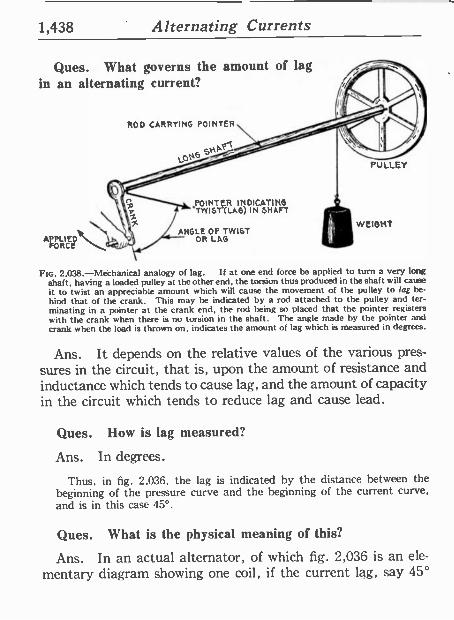
1,438 Alternating Currents
Ques. What governs the amount of lag in an alternating current?
FORCE
ROD CARRYING POINTER
POINTER INDICATING TWIST'CLAG) IN SHAFT
ANGLE OF TWIST OR LAG
PULLEY
WEIGHT
FIG. 2,038.-Mechanical analogy of lag. If at one end force be applied to turn a very long shaft, having a loaded pulley at the other end, the torsion thus produced in the shaft will cause ít to twist an appreciab.e amount which will cause the movement of the pulley to lag be- hind that of the crank. This may be indicated by a rod attached to the pulley and ter- minating in a pointer at the crank end, the rod being so placed that the pointer registers with the crank when there is no torsion in the shaft. The angle made by the pointer and crank when the load is thrown on, indicates the amount of lag which is measured in degrees.
Ans. It depends on the relative values of the various pres- sures in the circuit, that is, upon the amount of resistance and inductance which tends to cause lag, and the amount of capacity in the circuit which tends to reduce lag and cause lead.
Ques. How is lag measured?
Ans. In degrees.
Thus, in fig. 2,036, the lag is indicated by the distance between the beginning of the pressure curve and the beginning of the current curve, and is in this case 45°.
Ques. What is the physical meaning of this?
Ans. In an actual alternator, of which fig. 2,036 is an ele-
mentary diagram showing one coil, if the current lag, say 45°
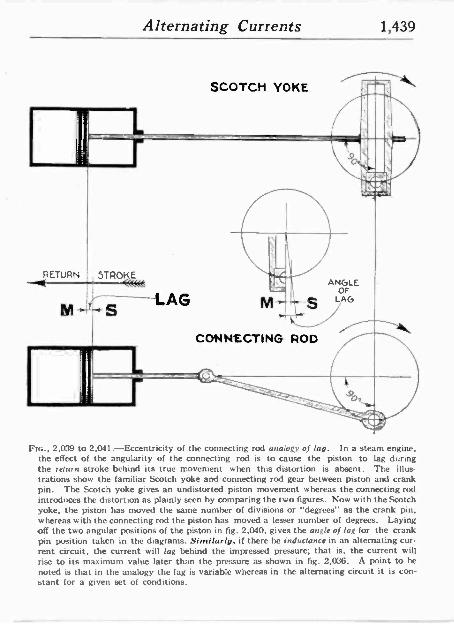
Alternating Currents 1,439
RETURN
M
SCOTCH YOKE
STROKE K«« S LAG
arlik Ivy
ANGLE OF
S LAG
CONNECTING ROD
FIG., 2,039 to 2.041.-Eccentricity of the connecting rod analogy of lag. In a steam engine, the effect of the angularity of the connecting rod is to cause the piston to lag during the return stroke behind its true movement when this distortion is absent. The illus- trations show the familiar Scotch yoke andconnecting rod gear between piston and crank pin. The Scotch yoke gives an undistorted piston movement whereas the connecting rod introduces the distortion as plainly seen by comparing the two figures. Now with the Scotch yoke, the piston has moved the same number of divisions or "degrees" as the crank pin, whereas with the connecting rod the piston has moved a lesser number of degrees. Laying off the two angular positions of the piston in fig. 2,040, gives the angle of lag for the crank pin position taken in the diagrams. Similarly, if there be inductance in an alternating cur- rent circuit, the current will lag behind the impressed pressure; that is, the current will rise to its maximum value later than the pressure as shown in fig. 2,036. A point to he noted is that in the analogy the lag is variable whereas ín the alternating circuit it is con- stant for a given set of conditions.
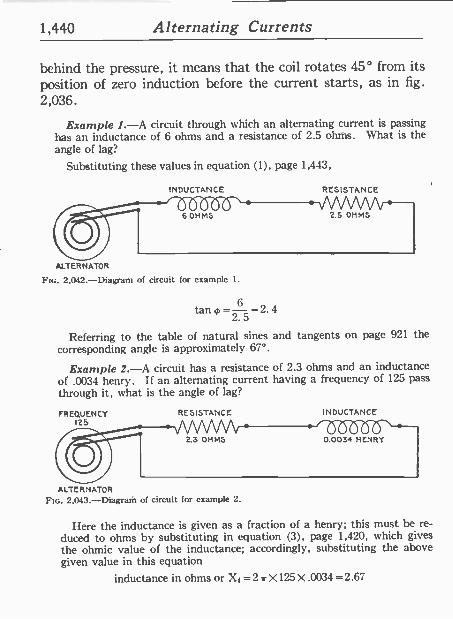
1,440 Alternating Currents
behind the pressure, it means that the coil rotates 45° from its position of zero induction before the current starts, as in fig. 2,036.
Example 1.-A circuit through which an alternating current is passing has an inductance of 6 ohms and a resistance of 2.5 ohms. What is the angle of lag?
Substituting these values in equation (1), page 1,443,
INDUCTANCE
6 OHMS
RESISTANCE
2.5 OHMS
ALTERNATOR
Frc. 2,042.-Diagram of circuit for example I.
tan 0=-6 25 ='2. 4
Referring to the table of natural sines and tangents on page 921 the corresponding angle is approximately 67°.
Example 2.-A circuit has a resistance of 2.3 ohms and an inductance of .0034 henry. If an alternating current having a frequency of 125 pass through it, what is the angle of lag?
FREQUENCY 125
RESISTANCE INDUCTANCE
075b(5(5'.-- 23 OHMS 0.0034 HENRY
ALTERNATOR
FIG. 2,043 -Diagram of circuit for example 2.
Here the inductance is given as a fraction of a henry; this must he re- duced to ohms by substituting in equation (3), page 1,420, which gives the ohmic value of the inductance; accordingly, substituting the above given value in this equation
inductance in ohms or Xi =2a X125 X .0034 =2.67
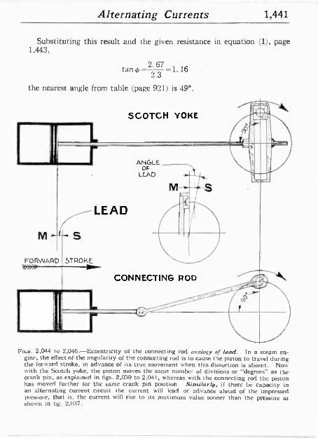
Alternating Currents 1,441
Substituting this result and the given resistance in equation (1), page 1.443,
tan 2.67 1.16 = 2.3
the nearest angle from table (page 921) is 49°.
LEAD
M ,ir S
FORWARD STROKE
SCOTCH YOKE
ANGLE OF
LEAD
CONNECTING ROD
Fins. 2,044 to 2,046.-Eccentricity of the connecting rod analogy of lead. In a steam en- gine, the effect of the angularity of the connecting rod is to cause the piston to travel during the forward stroke, in advance of its true movement when this distortion is absent. Now with the Scotch yoke, the piston moves the same number of divisions or "degrees" as the crank pin, as explained in figs. 2,039 to 2.041, whereas with the connecting rod the piston has moved further for the same crank pin position. Similarly, if there be capacity in an alternating current circuit the current will lead or advance ahead of the impressed pressure, that is, the current will rise to its maximum value sooner than the pressure as shown in fig. 2,037.
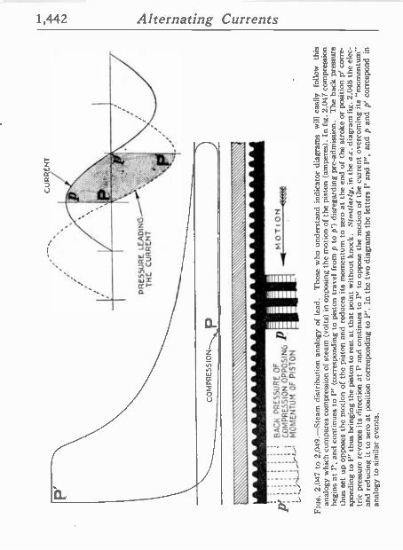
1,442 Alternating Currents
íí/
o
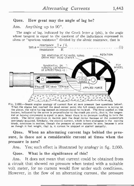
Alternating Currents 1,443
Ques. How great may the angle of lag be?
Ans. Anything up to 90°. The angle of lag, indicated by the Greek letter ¢ (phi), is the angle
whose tangent is equal to the quotient of the inductance expressed in ohms or "spurious resistance" divided by the ohmic resistance, that is
tan 4, -reactance _2 it f L (1)
resistance R
THE MOMENTUM OF FLY WHEEL TURNS CRANK PAST DEAD CENTER a
TANGENTIAL OR TURNING CDMPONENT OF APPLIED FORCE -0
ROTATION
40 _ FLY
WHEEL
Pte. 2,050.-Steam engine analogy of current flow at zero pressure (see questions below). When the engine has reached the dead center point the full steam pressure is acting on the piston, the valve having opened an amount equal to its lead. The force applied at this instant, indicated by the arrow is perpendicular to the crank pin circle, that is, the tangen- tial or turning component is equal -o zero, hence there is no pressure tending to turn the crank. The latter continues in motion past the dead cer.ter because of the momentum previously acquired. Similarly, the electric current, which is here analogous to the moving crank, continues in motion, though the pressure at some instants be zero, because it acts as though it had weight, that is, it cannot he stopped or started instantly.
Ques. When an alternating current lags behind the pres- sure, is there not a considerable current at times when the pressure is zero?
Ans. Yes; such effect is illustrated by analogy in fig. 2,050.
Ques. What is the significance of this? Ans. It does not mean that current could be obtained from
a circuit that showed no pressure when tested with a suitable volt meter, for no current would flow under such conditions. However, in the flow of an alternating current, the pressure
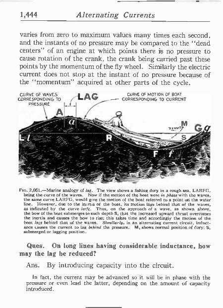
1,444 Alternating Currents
varies from zero to maximum values many times each second, and the instants of no pressure may be compared to the "dead centers" of an engine at which points there is no pressure to cause rotation of the crank, the crank being carried past these points by the momentum of the fly wheel. Similarly the electric current does not stop at the instant of no pressure because of the "momentum" acquired at other parts of the cycle.
CURVE OF WAVES CORRESPONDING TO
A
LAG
i---- '` ' - %,.
j¡, -
CURVE OF MOTION OF BOAT
CORRESPONDING TO CURRENT
".;; j.55 . ` -
M t,1r,
FIG. 2,051.-Marine analogy of lag. The view shows a fishing dory in a rough sea, LARFG, being the curve of the waves. Now if the motion of the boat were in phase with the waves. the same curve LARFG, would give the motion of the boat referred to a point on the water line. However, due to the inertia of the boat, its motion lags behind that of the waves, as indicated by the curve larfg. Thus, on the approach of a wave, as shown above, the bow of the boat submerges to such depth S, that the increased upward thrust overcomes the inertia and causes the bow to rise; this takes time and accordingly the motion of the boat lags behind that of the waves. Similarly. in an alternating current circuit, induct- ance causes the current to lag behind the pressure. M, shows normal position of dory; S, submerged or lagging position.
Ques. On long lines having considerable inductance, how may the lag be reduced?
Ans. By introducing capacity into the circuit.
In fact, the current may he advanced so it will be in phase with the pressure or even lead the latter, depending on the amount of capacity introduced.
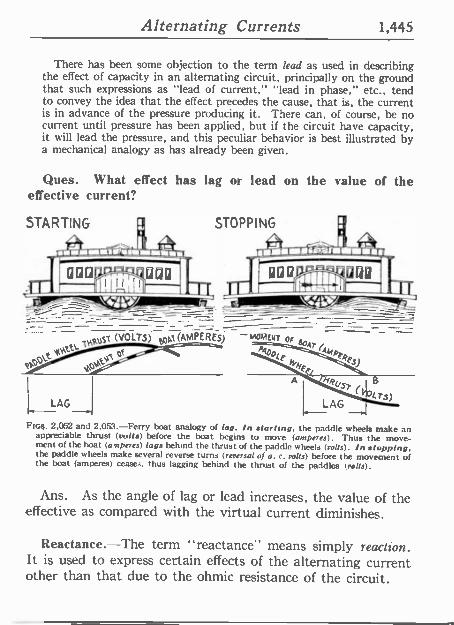
Alternating Currents 1,445
There has been some objection to the term lead as used in describing the effect of capacity in an alternating circuit, principally on the ground that such expressions as "lead of current," "lead in phase," etc., tend to convey the idea that the effect precedes the cause, that is, the current is in advance of the pressure producing it. There can, of course, be no current until pressure has been applied, but if the circuit have capacity, it will lead the pressure, and this peculiar behavior is best illustrated by a mechanical analogy as has already been given.
Ques. What effect has lag or lead on the value of the effective current?
STARTING :, STOPPING
Haust (VOLTS) ppt(AMPERE-) -MQMEUT oa a
p0
L LAG
Figs. 2,052 and 2,053.-Ferry boat analogy of lag. In starting, the paddle wheels make an appreciable thrust (volts) before the boat begins to move (amperes). Thus the move- ment of the boat (amperes) lags behind the thrust of the paddle wheels (volts). In stopping, the paddle wheels make several reverse turns (reversal of a. c. volts) before the movement of the boat (amperes) ceases, thus lagging behind the thrust of the paddles trolls).
Ans. As the angle of lag or lead increases, the value of the effective as compared with the virtual current diminishes.
Reactance.-The term "reactance" means simply reaction. It is used to express certain effects of the alternating current other than that due to the ohmic resistance of the circuit.
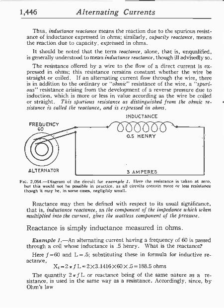
1,446 Alternating Currents
Thus, inductance reactance means the reaction due to the spurious resist- ance of inductance expressed in ohms; similarly, capacity reactance, means the reaction due to capacity, expressed in ohms.
It should be noted that the term reactance, alone, that is, unqualified, is generally understood to mean inductance reactance, though ill advisedly so.
The resistance offered by a wire to the flow of a direct current is ex- pressed in ohms; this resistance remains constant whether the wire be straight or coiled. If an alternating current flow through the wire, there is in addition to the ordinary or "ohmic" resistance of the wire, a "spuri- ous" resistance arising fromthe development of a reverse pressure due to induction, which is more or less in value according as the wire be coiled or straight. This spurious resistance as distinguished from the ohmic re- sistance is called the reactance, and is expressed in ohms.
FREQUENCY 60
ALTERNATOR
INDUCTANCE
0.5 HENRY
3 AMPERES
FIG. 2,054.-Diagram of the circuit for example 1. here the resistance is -taken at zero. hut this would not he possible in practice. as all circuits contain more or less resistance though it may be, in some cases, negligibly small.
Reactance may then he defined with respect to its usual significance, that is, inductance reactance, as the component of the impedance which when multiplied into the current, gives the u'attless component of the pressure.
Reactance is simply inductance measured in ohms.
Example 1.-An alternating current having a frequency of 60 is passed through a coil whose inductance is .5 henry. What is the reactance?
Here f=60 and L=.5; substituting these in formula for inductive re- actance,
X1=2 71 f L=2 X3.1416X60X .5=188.5 ohms
The quantity 2 >r f L or reactance being of the same nature as "a re- sistance, is used in the same way as a resistance. Accordingly, since, by Ohm's law
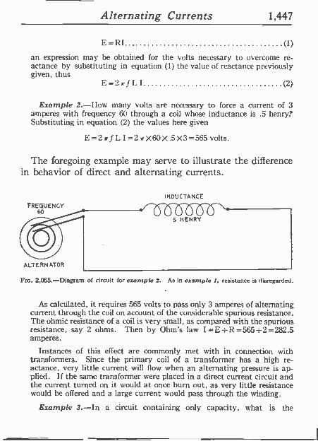
Alternating Currents 1,447
E=RI (1)
an expression may he obtained for the volts necessary to overcome re- actance by substituting in equation (1) the value of reactance previously given, thus
E=2 I (2)
Example 2.-I low many volts are necessary to force a current of 3 amperes with frequency 60 through a coil whose inductance is .5 henry? Substituting in equation (2) the values here given
E=27r f L I =27rX60X.5X3=565 volts.
The foregoing example may serve to illustrate the difference in behavior of direct and alternating currents.
INDUCTANCE
FREQUENCY 60
5 HENRY
ALTERNATOR
2,055.-Diagram of circuit for example 2. As in example 1. resistance is disregarded.
As calculated, it requires 565 volts to pass only 3 amperes of alternating current through the coil on account of the considerable spurious resistance. The ohmic resistance of a coil is very small, as compared with the spurious resistance, say 2 ohms. Then by Ohm's law I=E=R=565=2=282.5 amperes.
Instances of this effect are commonly met with in connection with transformers. Since the primary coil of a transformer has a high re- actance, very little current will Ilow when an alternating pressure is ap- plied. If the same transformer were placed in a direct current circuit and the current turned on it would at once burn out, as very little resistance would be offered and a large current would pass through the winding.
Example 3.-In a circuit containing only capacity, what is the
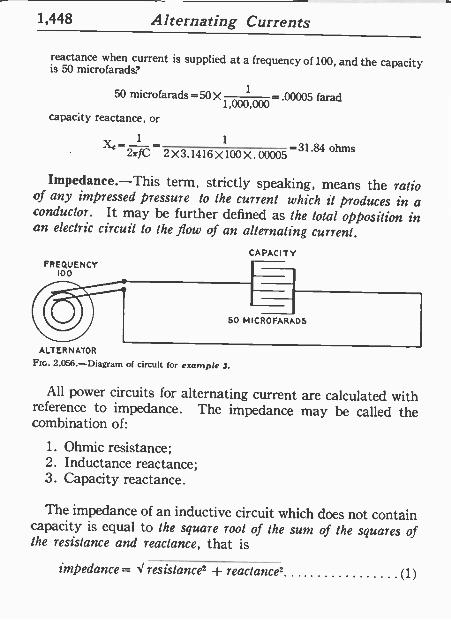
1,448 Alternating Currents
reactance when current is supplied at a frequency of 100, and the capacity is 50 microfarads.
50 microfarads =50 X 1 = .00005 farad 1,000,000
capacity reactance, or
l",_ 1 1
2TrfC -
2X3.1416X 100X.00005 -31.84 ohms
Impedance.-This term, strictly speaking, means the ratio of any impressed pressure to the current which it produces in a conductor. It may be further defined as the total opposition in an electric circuit to the flow of an alternating current.
FREQUENCY 100
CAPACITY
50 MICROFARAD5
ALTERNATOR Ftc. 2,056.-Diagram of circuit for example .1.
All power circuits for alternating current are calculated with reference to impedance. The impedance may be called the combination of:
1. Ohmic resistance; 2. Inductance reactance; 3. Capacity reactance.
The impedance of an inductive circuit which does not contain capacity is equal to the square root of the sum of the squares of the resistance and reactance, that is
impedance = resistance2 reactance= (1)
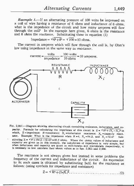
Alternating Currents 1,449
Example 1.-If an alternating pressure of 100 volts be impressed on a coil of wire having a resistance of 6 ohms and inductance of 8 ohms, what is the impedance of the circuit and how many amperes will flow through the coil? In the example here given, 6 ohms is the resistance and 8 ohms the reactance. Substituting these in equation (1)
Impedance = d6=+82 = < 100 =10 ohms. The current in amperes which will flow through the coil is, by Ohm's
law using impedance in the same way as resistance.
volts 100 volts -10 amperes. currentimpedance 10 ohms
ALTERNATOR-
RESISTANCE
R
I N DUCTANCE
'ÓÓSÓÓ-` X
CAPACITY
xc FIG. 2,057.-Diagram showing alternating circuit containing resistance, inductance, and ca-
pacity. Formula for calculating the impedance of this circuit is Z= R'+ -(X; -X,)' in which, Z =impedance; R =resistance; Xi =inductance reactance; X, =capacity react- ance. Example: What is the impedance when R =4, X, =94.2, and X, =72.4? Sub- stituting Z= <4'}(94.2-72.4)'=22 =22.2 ohms. where the ohmic values of inductance and capacity are given as in this example, the calculation of impedance is very simple, but when inductance and capacity are given in milli -henrys and microfarads respectively, it is necessary to first calculate their ohmic values as in figs. 2,055 and 2,056.
The reactance is not always given but instead in some problems the frequency of the current and inductance of the circuit. An expression to fit such cases is obtained by substituting 27rfL for the reactance as follows: (using symbols for impedance and resistance)
Z= <R2+(Z,rfL), (2)
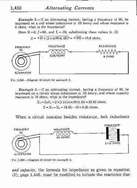
1,450 Alternating Currents
Example 2.-If an alternating current, having a frequency of 60, he impressed on a coil whose inductance is .05 henry and whose resistance is 6 ohms, what is the impedance?
I Iere R =6; f =60, and L = .05; substituting these values in (2)
Z='62+(2 a X60X.05)2= <393=19.8 ohms.
FREQUENCY 60
ALTERNATOR
INDUCTANCE
Plc. 2,058.-Diagram of circuit for example 2.
RESISTANCE
Example 3.-If an alternating current, having a frequency of 60, be impressed on a circuit whose inductance is .05 henry, and whose capacity reactance is 10 ohrr.s, what is the impedance.'
X1=2irfL=2 X3.1416X60X.05=18.85 ohms.
Z=X1-X,=18.85-10=8.85 ohms.
When a circuit contains besides resistance, both inductance
FREQUENCY 60
ALTERNATOR
INDUCTANCE
.05 HENRY
CONDENSER'
C.10 OHMS
FIG. 2,059.-Diagram of circuit for example 3.
and capacity, the formula for impedance as given in equation (1), page 1,448, must he modified to include the reactance due
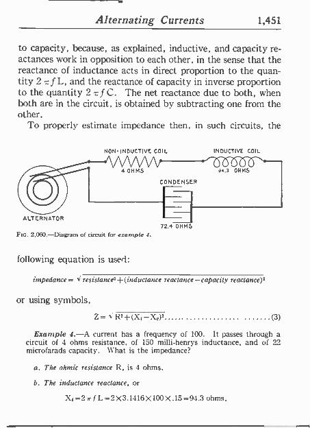
Alternating Currents 1,451
to capacity, because, as explained, inductive, and capacity re- actances work in opposition to each other, in the sense that the reactance of inductance acts in direct proportion to the quan- tity 2 7f L, and the reactance of capacity in inverse proportion to the quantity 2 -f C. The net reactance due to both, when both are in the circuit, is obtained by subtracting one from the other.
To properly estimate impedance then, in such circuits, the
NON -INDUCTIVE COIL
ALTERNATOR 72.4 OHMS
FIG. 2.060.-Diagram of circuit for example J.
following equation is used:
INDUCTIVE COIL
impedance = < resistance2+(inductance reactance -capacity reaclance)2
or using symbols,
Z= R2+ (XI -\t)2 (3)
Example 4.-A current has a frequency of 100. It passes through a circuit of 4 ohms resistance, of 150 milli -henrys inductance, and of 22 microfarads capacity. Chat is the impedance?
a. The ohmic resistance 12, is 4 ohms.
b. The inductance reactance, or
Xi=2rf L=2X3.1416X100X.15=94.3 ohms.
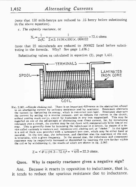
1,452 Alternating Currents
(note that 150 milli -henrys are reduced to .15 henry before substituting in the above equation).
c. The capacity reactance, or
1 1
X` -72'4 ohms 2 JC 2X3. 1416 X100 X. 000022
(note that 22 microfarads are reduced to .000022 farad before substi- tuting in the formula. Why? See page 1,426.)
Substituting values as calculated in equation (3), page 1,451.
SPOOL
TERMINALSy
it__-__==", 1111111111!P
LAMINATED IRON CORE
iiiii : COIL
FIG. 2,061.-Simple choking coil. There is an important difference in the obstruction offered
to an alternating current by ordinary resistance and by reactance. Resistance obstructs the current by dissipating its energy, which is converted into heat. Reactance obstructs the current by setting up a reverse pressure, and so reduces the current in the circuit, without wasting much energy, except by hysteresis in any iron magnetized. This may be regarded as one of the advantages of alternating over direct current, for, by introducing reactance into a circuit, the current may be cut clown with comparatively little loss of en-
ergy. This is generally done by increasing the inductance in a circuit, by means of a de-
vice called variously a reactance coil, impedance coil, choking coil, or "choker." In the figure
is a coil of thick wire provided with a laminated iron core, which may be either fixed or
movable. In the first case, the inductance. and therefore also the reactance of the coil, is invariable, with a given frequency. In the second case, the inductance and consequent
reactance may be respectively increased or diminished by inserting the core farther within the coil or by withdrawing it, the results of which arc shown in fig. 2,062.
Z= X42+(94.3-72.4)2= X495=22.3 ohms.
Ques. Why is capacity reactance given a negative sign?
Ans. Because it reacts in opposition to inductance, that is,
it tends to reduce the spurious resistance due to inductance.
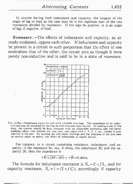
Alternating Currents 1,453
In circuits having both inductance and capacity, the tangent of the angle of lag or lead as the case may be is the algebraic sum of the two reactances divided by resistance. If the sign he positive, it is an angle of lag; if negative, of lead.
Resonance.-The effects of inductance and capacity, as al- ready explained, oppose each other. If inductance and capacity be present in a circuit in such porportion that the effect of one neutralizes that of the other, the circuit acts as though it were purely non -inductive and is said to be in a state of resonance.
25
n 20
ZIS
Z
i lo
o
Rl51STANCE.1.601M5
CURRENT 4 A.
IMPEDANCE VOLT[
-.1 OHM
0 0 3 4 5 6 7 $ 9 10 1710115 01 IRON CORE
Ftc. 2.062.-Impedance curve for coil with variable iron core. The impedance of an induc- tive coil may be increased by moving an iron wire core into the coil. In making a test of this kind, the current should be kept constant with an adjustable resistance, and volt meter readings taken. first without the iron core, and again with 1, 2, 3, 4. etc., inches of core inserted in the coil. By plotting the volt meter readings and the positions of the iron core on section paper as above, the effect of inductance is clearly shown.
For instance, in a circuit containing resistance, inductance, and ca- pacity, if the resistance he, say, 8 ohms, the inductance 30, and the ca- pacity 30, then the impedance is
82 + (302-302) = d I= 8 ohms.
The formula for inductance reactance is Xi =2 7. f L, and for capacity reactance, X, =1= (2 r, f C); accordingly if capacity
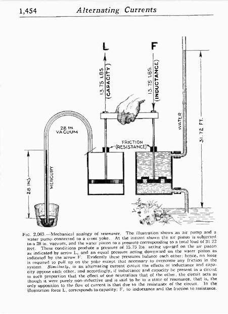
1,454 Alternating Currents
FIG. 2,063.-Mechanical analogy of resonance. The illustration shows an air pump and a
water pump connected to a crass yoke. At the instant shown the air piston is subjected
to a 28 in. vacuum, and the water piston to a pressure corresponding to a total load of 31.72
feet. These conditions produce a pressure of 13.75 lbs. acting upward on the air piston
as indicated by arrow L, and an equal pressure acting downward on the water piston as
indicated by the arrow F. Evidently these pressures balance each other; hence, no force
is required to pull up on the yoke except that necessary to overcome any friction in the
system. Similarly. in an alternating current circuit the effects of inductance and capa-
city oppose each other, and accordingly, if inductance and capacity be present in a circuit in such proportion that the effect of one neutralizes that of the other, the circuit acts as
though it were purely non -inductive and is said to be in a state of resonance, that is, the
only opposition to the flow of current is that due to the resistance of the circuit. In the
illustration force L, corresponds to capacity; F', to inductance and the friction to resistance.
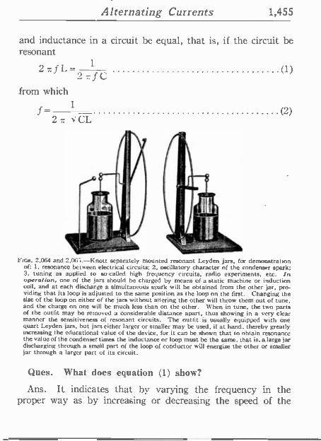
Alternating Currents 1,455
and inductance in a circuit be equal, that is, if the circuit be resonant
2afL- 1 (1) 2 r f C
from which 1 f-
2 z JCL
Fros. 2,064 and 2.065.-Knott separately mounted resonant Leyden jars, for demonstration of: 1, resonance between electrical circuits; 2, oscillatory character of the condenser spark; 3, tuning as applied to so called high frequency circuits, radio experiments, etc. In operation, one of the jars should be charged by means of a static machine or induction coil, and at each discharge a simultaneous spark will be obtained from the other jar, pro- viding that its loop is adjusted to the same position as the loop on the first. Changing the size of the loop on either of the jars without altering the other will throw them out of tune, and the charge on one will be much less than on the other. When in tune, the two parts of the outfit may be removed a considerable distance apart, thus showing in a very clear manner the sensitiveness of resonant circuits. The outfit is usually equipped with one quart Leyden jars, but jars either larger or smaller may be used, if at hand. thereby greatly increasing the educational value of the device, for it can be shown that to obtain resonance the value of the condenser times the inductance or loop must be the same, that is, a large jar discharging through a small part of the loop of conductor will energize the other or smaller jar through a larger part of its circuit.
(2)
Ques. What does equation (1) show?
Ans. It indicates that by varying the frequency in the proper way as by increasing or decreasing the speed of the
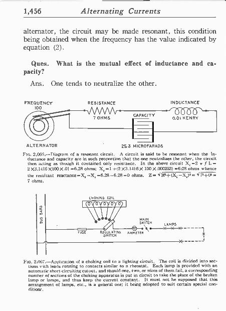
1,456 Alternating Currents
alternator, the circuit may be made resonant, this condition being obtained when the frequency has the value indicated by equation (2).
Ques. What is the mutual effect of inductance and ca- pacity?
Ans. One tends to neutralize the other.
FREQUENCY 100
ALTERNATOR
RESISTANCE INDUCTANCE
7 OHMS CAPACITY
253 MICROFARADS
0.01 HENRY
FIG. 2,065.-lliagram of a resonant circuit. A circuit is said to be resonant when the in- ductance and capacity are in such proportion that the one neutralizes the other, the circuit then acting as though it contained only resistance. In the above circuit X, =2 ,r f L = 2 X3.1416 X100 X.01 =6.28 ohms; Xr =1 = (2 X3.1416 X 100 X.1253) =6:28 ohms whence
the resultant reactance ---X, -X, =6.28 -6.28 =0 ohms. Z = J R=+ (X, -XX _ < 7++02 = 7 ohms.
CHOKING COIL
MAIN SWITCH LAMPS
USE REGULATING AMMETER \
$W ITCR
FIG. 2 067.-Application of a choking coil to a lighting circuit. The coil is divided into sec- tions with leads running to contacts similar to a rheostat. Each lamp is provided with an automatic short-circuiting cutout, and should one, two, or more of them fail, a corresponding number of sections of the choking apparatus is put in circuit to take the place of the broken lamp or lamps, and thus keep the current constant. It must not be supposed that this arrangement of lamps, etc., is a general one; it being adopted to suit certain special con- dit Tone.
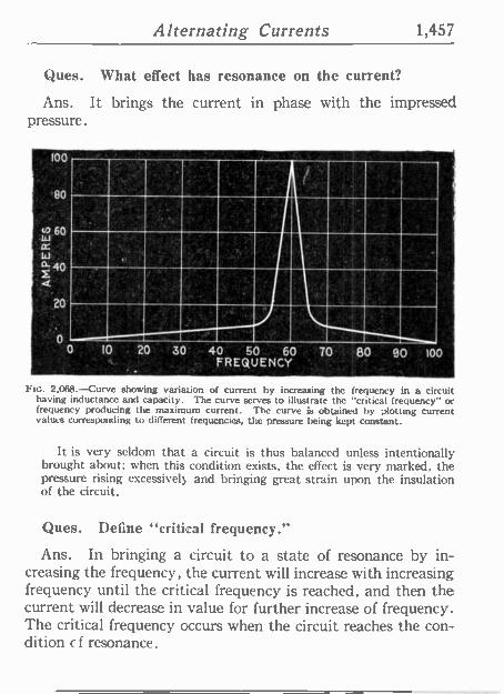
Alternating Currents 1,457
Ques. What effect has resonance on the current?
Ans. It brings the current in phase with the impressed pressure.
v 100
' '80
60 w cc W '
F 40
.,.. I
hr ®® 111 V.
® - 40 - 50 -60 - 70 80 90 '100
FREQUENCY ' : °
U
0 10 . 20 30' a.' . FIG. 2.068. --Curve showing variation of current by increasing the frequency in a circuit
having inductance and capacity. The curve serves to illustrate the "critical frequency" or frequency producing the maximum current. The curves obtained by plotting current values corresponding to different frequencies, the pressure being kept constant.
It is very seldom that a circuit is thus balanced unless intentionally brought about; when this condition exists, the effect is very marked, the pressure rising excessively and bringing great strain upon the insulation of the circuit.
Ques. Define "critical frequency."
Ans. In bringing a circuit to a state of resonance by in- creasing the frequency, the current will increase with increasing frequency until the critical frequency is reached, and then the current will decrease in value for further increase of frequency. The critical frequency occurs when the circuit reaches the con- dition c f resonance.
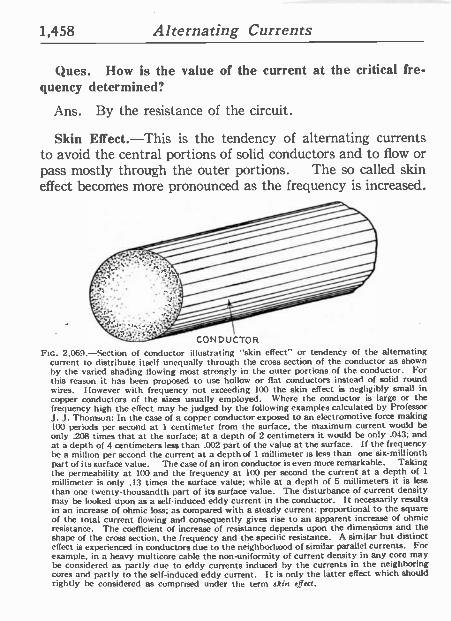
1,458 Alternating Currents
Ques. How is the value of the current at the critical fre- quency determined?
Ans. By the resistance of the circuit.
Skin Effect.-This is the tendency of alternating currents to avoid the central portions of solid conductors and to flow or pass mostly through the outer portions. The so called skin effect becomes more pronounced as the frequency is increased.
FIG. 2.069.-Section of conductor illustrating "skin effect" or tendency of the alternating current to distribute itself unequally through the cross section of the conductor as shown by the varied shading flowing most strongly in the outer portions of the conductor. For this reason it has been proposed to use hollow or flat conductors instead of solid round wires. However with frequency not exceeding 100 the skin effect is negligibly small in copper conductors of the sizes usually employed. Where the conductor is large or the frequency high the effect may be judged by the following examples calculated by Professor J. J. Thomson: In the case of a copper conductor exposed to an electromotive force making 100 periods per second at 1 centimeter from the surface, the maximum current would be only .208 times that at the surface; at a depth of 2 centimeters it would be only .043; and at a depth of 4 centimeters less than .002 part of the value at the surface. If the frequency be a million per second the current at a depth of 1 millimeter is less than one six -millionth part of its surface value. The case of an iron conductor is even more remarkable. Taking the permeability at 100 and the frequency at 100 per second the current at a depth of 1
millimeter is only .13 times the surface value; while at a depth of 5 millimeters it is less than one twenty -thousandth part of its surface value. The disturbance of current density may be looked upon as a self-induced eddy current in the conductor. It necessarily results in an increase of ohmic loss; as compared with a steady current: proportional to the square of the total current flowing and consequently gives rise to an apparent increase of ohmic resistance. The coefficient of increase of resistance depends upon the dimensions and the shape of the cross section. the frequency and the specific resistance. A similar but distinct effect is experienced ín conductors due to the neighborhood of similar parallel currents. For example, in a heavy multicore cable the non -uniformity of current density in any core may be considered as partly due to eddy currents induced by the currents in the neighboring cores and partly to the self-induced eddy current. It is only the latter effect which should rightly be considered as comprised under the term skin effect.
Alternating Currents 1,459
Ques. What is the explanation of skin effect?
Ans. It is due to eddy currents induced in the conductor.
Consider the wire as being composed of several small insulated wires
placed closely together. Now when a current is started along these sep-
arate wires, mutual induction will take place between them, giving rise
to momentary reverse pressures. Those wires which are nearer the center, since they are completely surrounded by neighboring wires, will clearly have stronger reverse pressures set up in them than those on or near the outer surface, so that the current will meet less opposition near the sur- face than at the center, and consequently the flow will be greater in the outer portions.
Ques. What is the result of skin effect?
Ans. It results in an apparent increase of resistance.
The coefficient of increase of resistance depends upon the dimensions and the shape of the cross section, the frequency, and the specific re-
sistance. Hughes, about 1883, called attention to the fact that the resistance of
an iron telegraph wire was greater for rapid periodic currents than for steady currents.
In 1888 Kelvin showed that when alternating currents at moderately high frequency flow through massive conductors, the current is prac- tically confined to the skin, the interior portions being largely useless for the purpose of conduction. The mathematical theory of the subject has
been developed by Kelvin, I leaviside, Rayleigh, and others.
TEST QUESTIONS
1. Define alternating currents. 2. What are the advantages and disadvantages of al-
ternating currents? 3. State alternating current principles. 4. What is the application of the sine curve?
5. What is the meaning of the equation y=sino ?
6. What is an alternation?
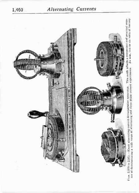
0
^- ' .
3 I
R
I
---.
-1
,r _
- .-
.;.
' . .1.1
-,:. _:
--
.
- -
--/
11_
-
, :
TI
kn
nos.
2,0
70 t
o 2.
073.
-Kno
tt al
tern
atin
g cu
rren
t de
mon
stra
tion
appa
ratu
s.
Thi
s ou
tfit
affo
rds
a co
nven
ient
'and
pr
actic
al m
an-
ner
of d
emon
stra
ting
a w
ide
rang
e of
alte
rnat
ing
and
thre
e ph
ase
curr
ent
expe
rim
ents
. In
use
, tw
o to
six
vol
ts o
f ba
ttery
_,
.C -y
'
-' -
Alternating Currents 1,461
7. What is the amplitude of the current? 8. Define the terms period and frequency. 9. What frequencies are used in com-
mercial machines? 10. What is the advantage of low frequency? 11. What is phase? 12. Explain the terms in phase and out of
phase. 13. What is synchronism? 14. What is the difference between maxi-
mum, average and virtual volts? 15. What are effective volts and amperes? 16. What is the expression for form factor
and what does it indicate? 17. What is the relation between the shape
of the wave curve and the form factor? 18. What determines the form of the wave? 19. What is single phase current? 20. Describe two phase and three phase
current. 21. Give hydraulic analogy illustrating the
difference between direct (contin- uous) and alternating current.
22. How must an alternator be constructed to generate two phase current?
23. How many wires are required for two phase and three phase distribution?
24. How is three phase current generated? 25. What is induction? 26. Describe an experiment illustrating self
induction in an alternating current circuit.
1,462 Alternating Currents
27. What is the difference between ohmic and spurious resistance?
28. What is the unit of induction? 29. What other name is given to the henry? 30. What is the formula for the henry? 31. Give hydraulic and mechanical analogy of induction. 32. Describe a choke coil. 33. What is the ohmic value of inductance? 34. Define capacity. 35. Give hydraulic analogy illustrating capacity. 36. What is the effect of capacity? 37. Name the unit of capacity and define it.
38. Explain the effect of a condenser in direct and alter- nating current circuits.
39. What is specific inductive capacity? 40. How are capacity tests usually made? 41. What is the ohmic value of capacity? 42. What is the difference between lag and lead? Define
each. 43. How does inductance cause the current to lag behind
the pressure? 44. How is lag measured? 45. Give analogies of lag and lead. 46. How great may the angle of lag be?
47. Can there be current flow at zero pressure? 48. Define reactance. 49. What is impedance? 50. What is resonance? 51. Give mechanical analogy of resonance. 52. What is the mutual effect of inductance and capacity? 53. Explain the terms critical frequency and skin effect.
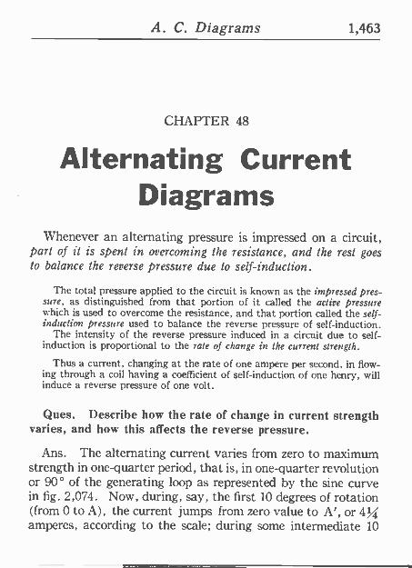
A. C. Diagrams 1,463
CHAPTER 48
Alternating Current Diagrams
Whenever an alternating pressure is impressed on a circuit, part of it is spent in overcoming the resistance, and the rest goes to balance the reverse pressure due to self-induction.
The total pressure applied to the circuit is known as the impressed pres- sure, as distinguished from that portion of it called the active pressure which is used to overcome the resistance, and that portion called the self- induction pressure used to balance the reverse pressure of self-induction.
The intensity of the reverse pressure induced in a circuit due to self- induction is proportional to the rate of change in the current strength.
Thus a current, changing at the rate of one ampere per second, in flow- ing through a coil having a coefficient of self-induction of one henry, will induce a reverse pressure of one volt.
Ques. Describe how the rate of change in current strength varies, and how this affects the reverse pressure.
Ans. The alternating current varies from zero to maximum strength in one -quarter period, that is, in one -quarter revolution or 90° of the generating loop as represented by the sine curve in fig. 2,074. Now, during, say, the first 10 degrees of rotation (from 0 to A), the current jumps from zero value to A', or 4% amperes, according to the scale; during some intermediate 10
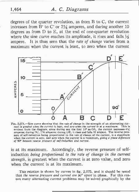
1,464 A. C. Diagrams
degrees of the quarter revolution, as from B to C, the current increases from B' to C' or 2% amperes, and during another 10 degrees as from D to E, at the end of one -quarter revolution where the sine curve reaches its amplitude, it rises and falls ampere. It is thus seen that the rate of change varies from a maximum when the current is least, to zero when the current
15.
10
5
D'I É I `
o A BC 90°
DIE Fin. 2,074.-Sine curve showing that the rate of change in the strength of an alternating cur-
rent is greatest when the current is least, and zero when the current is at a maximum. This is evident from the diagram, since during say the first 10° as OA, the current increases 4.4 amperes; during BC, 2% amperes; during DE, it rises and falls Ys ampere. The reverse pres- sure of self-induction being proportional to the rate of change of the current, is a maximum when the current is zero, and zero when the current is a maximum, giving a phase difference of 90° between reverse pressure of self-induction and current.
is at its maximum. Accordingly, the reverse pressure of self- induction being proportional to the rale of change in the current strength, is greatest when the current is at zero value, and zero when the current is at its maximum.
This relation is shown by curves in fig. 2,075, and it should be noted that the reverse pressure and current are 90° apart in phase. For this rea- son many alternating current problems may be solved graphically by the
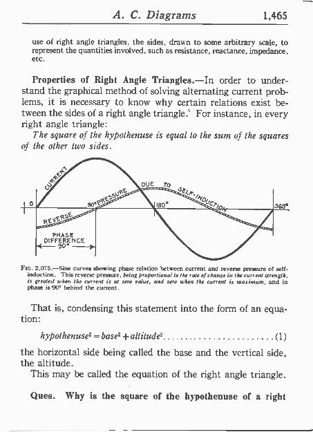
A. C. Diagrams 1,465
use of right angle triangles, the sides, drawn to some arbitrary scale, to represent the quantities involved, such as resistance, reactance, impedance, etc.
Properties of Right Angle Triangles.-In order to under- stand the graphical method of solving alternating current prob- lems, it is necessary to know why certain relations exist be- tween the sides of a right angle triangle.' For instance, in every right angle triangle:
The square of the hypothenuse is equal to the sum of the squares of the other two sides.
PHASE DIFFERENCE go'
Frc. 2,075.-Sine curves showing phase relation between current and reverse pressure of self- induction. This reverse pressure, being proportional to the rate of change in the current strength, is greatest when the current is at zero value, and zero when the current is maximum, and in phase is 900 behind the current.
That is, condensing this statement into the form of an equa- tion:
hypothenuse2 = base' +altitude' (1)
the horizontal side being called the base and the vertical side, the altitude.
This may be called the equation of the right angle triangle.
Ques. Why is the square of the hypothenuse of a right
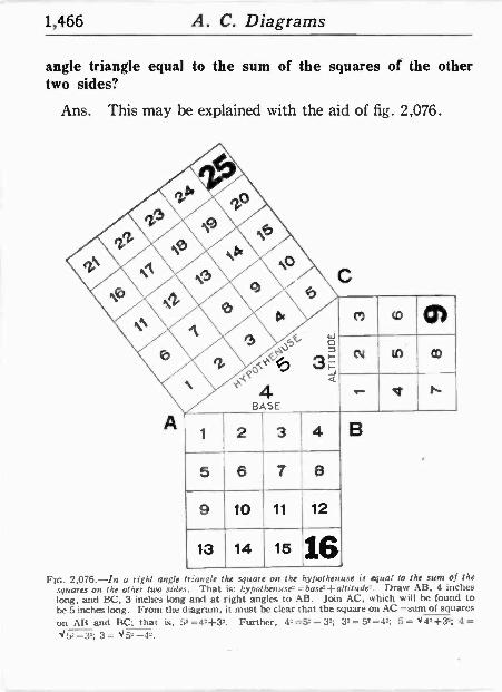
1,466 A. C. Diagrams
angle triangle equal to the sum of the squares of the other two sides?
Ans. This may be explained with the aid of fig. 2,076.
c
5 6 7 8
9 10 11 12
13 14 15 16
co
N
nt
m
ti
FIG. 2,076.-In a right angle riangle the square on the hypothen :se is equal to the sum of the squares on the other two sides. That is: hypathenuse2 =base2+altitude. Draw AB, 4 inches long, and BC, 3 inches long and at right angles to AB. Join AC, which will be found to he 5 inches long. From the diagram, it must be clear that the square on AC =sum of squares
on AB and BC: that is, 52 =42+32. Further, 42 =52 - 32; 32 = 52-42; 5= '1 42+32; 4 = Jy-32; 3= <52 -42.
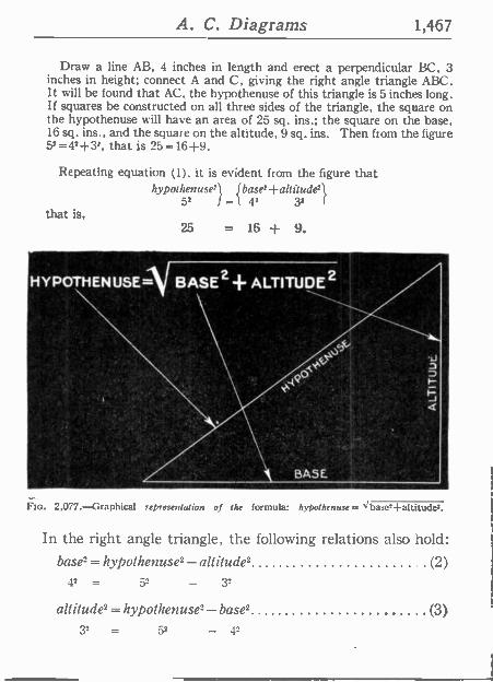
A. C. Diagrams 1,467
Draw a line AB, 4 inches in length and erect a perpendicular BC, 3 inches in height; connect A and C, giving the right angle triangle ABC. It will be found that AC, the hypothenuse of this triangle is 5 inches long. If squares be constructed on all three sides of the triangle, the square on the hypothenuse will have an area of 25 sq. ins.; the square on the base, 16 sq. ins., and the square on the altitude, 9 sq. ins. Then from the figure 52=42+31, that is 25=16+9.
Repeating equation (1). it is evident from the figure that hyposhe useal Ibase'+all3u"` de
52 I 42
that is, 25 = 16 + 9.
HYPOTHENUSE= BASE2-- ALTITUDE2
Flu. 2,077.-Graphical representation of the formula: hypothenuse = abase- altitude
In the right angle triangle, the following relations also hold: base2 = hypothenuse, - alt itude2 (2)
42 = 52 - 32
altitude2 = hypothenuse"- base' (3) 32 = 5" - 4"
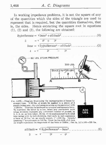
1,468 A. C. Diagrams
3'
In working impedance problems, it is not the square of any of the quantities which the sides of the triangle are used to represent that is required, but the quantities themselves, that is, the sides. Hence extracting the square root in equations (1), (2) and (3), the following are obtained:
h}polheuuse= < base, +altilude' (4)
5 = 4' + 3'
base = hypothenuse2-altitude' (5)
4 = \' 5'
-80 IBS STEAM PRESSURE
Fin. 2,078.-Diagram illustrating the representation of forces by straight lines. If 80 lbs. of steam be applied to a piston of 4
square inches area, the total pressure acting on the piston is 4 X80 =320 lbs. This may be balanced by an equal and opposite force. 7 `' To represent the latter by a line, select any convenient scale ' 320' whose divisions represent any convenient number of pounds, as
` LBS, 1, 3, 5, or, as here taken, 25 lbs. 1 f the scale selected be divided into inches with 3 -inch divisions, then each 5 inch represents a force of 25 lbs.: or, as usually stated, 1" =100 lbs. Strictly 1 ' speaking 1"isequivalent 10100 lbs. Draw the line A B =3.2 then its length represents the magnitude of the force or 320lbs., that is, 3.2 X100 =320 lbs.
altitude = <hypothenuse2-base, (6)
3 = 5' - 4'
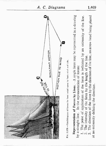
uotlaaaip aril 2utugap Áltutauxa uc
panic' pen M
ot.re un 'au!' am Jo uotra.ttp
aa.to; alp jo uoma.np atiZ
£
-auq jo tiO
uai ato. Ág aa.roj alp jo Á
itsualut au, 17
auq aql jo Áltrua.tpca
uc pajcatput
sr aa.toj agl jo uotletidde jo lutod au T
:satoj jo uojlcw
asaida.t ato ui auui iqpc.rjs e Á
Sutmu.rp u ut pa;uasaida.r ag ,icui aa.toj ailuts d-saurj Á
q saa.rod jo uoilejuasaadag
a
-apr, pue plum gtog dq uodn page leoq
saaJoj jo weaeofalreled-61A
Z 0i3
c. - w
_- _
_ _,.,... g -3
NO
1101"1 1Nt/11f153tJ
-
QN
I at.
3110 N011ol.y
0l 1aV
i 1
--2._ 1_-.
'114 3
\ _
-IO
ª1 1
3 %
i
(' r
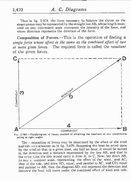
1,470 A. C. Diagrams
Thus in fig. 2,078, the force necessary to balance the thrust on the steam piston may be represented by the straight line AB, whose length meas- ured on any convenient scale represents the intensity of the force, and whose direction represents the direction of the force.
Composition of Forces.-This is the operation of finding a single force whose effect is the same as the combined effect of two
or more given forces. The required force is called the resultant of the given forces.
C
4 COMPONENT
D
Fte. 2.080.-Parallelogram of forces; method of obtaining the resultant of two components acting at right angles.
The composition of forces may he illustrated by the effect of the wind and tide on a schooner as in fig. 2.079. Supposing the boat be acted upon by the wind so that in a given time, say half an hour, it would be moved in the direction and a distance represented by the line AB, and that in
the same time the tide would carry it from A, to C. Now, lay down AB, to any c:-ivenient scale, representing the effect of the wind, and AC, that of the tide, and draw BD, equal, and parallel to AC, and CD, equal and parallel to AB, then the diagonal AD, will represent the direction and distance the boat will move under the combined effect of wind and tide.
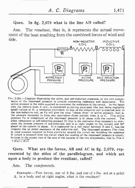
A. C. Diagrams 1,471
Ques. In fig. 2,079 what is the line AD called?
Ans. The resultant, that is, it represents the actual move- ment of the boat resulting from the combined forces of wind and tide. NON -INDUCTIVE INDUCTIVE
COIL B
Colt.
t
ACTIVE SELF INDUCTION PRESSURE. PRESSURE
Ftc. 2,081.-Diagram illustrating the active, and self-induction pressures, or the two compo- nents of the impressed pressure in circuits containing resistance and inductance. The active pressure is the volts required to overcome the resistance of the circuit. In the figure only the portion from A toC, is considered as having resistance (the rest being negligibly small) except at R. a resistance equivalent to that of the inductive coil is inserted next to the non -inductive coil, so Pa will give the total "ohmic drop" or active pressure. that is, the pressure necessary to force any equivalent direct current from A to C. This active pressure Pa or component of the impressed pressure is in phase with the current. The other component.or self-induction pressure Pi that is the reactance drop necessary to over- come the reverse pressure of self-induction and is at right angles to the current and 90° ahead of the current in phase. It is registered by a volt meter between B and C. less the pressure due to ohmic resistance of the inductive coil. The impressed pressure Pins then or total pressure required to force electricity around the circuit not inciuding the tesistance 12 (which is removed from the circuit when the reading of the impressed pressure is taken), is equal to the square root of the sum of the squares of the two component:;, that is, Pint=
(Pa) 2+ (P02.
Ques. What are the forces, AB and AC in fig. 2,079, rep- resented by the sides of the parallelogram, and which act upon a body to produce the resultant, called?
Ans. The components.
Example.-Two forces, one of 3 1hs. and one of 4 lbs. act at a point A, in a body and at right angles, what is the resultant?
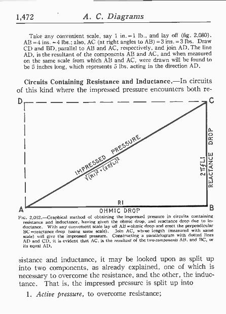
1,472 A. C. Diagrams
Take any convenient scale, say 1 in. =1 lb., and lay off (fig. 2,080). AB =4 ins. =4 lbs.; also, AC (at right angles to AB) =3 ins. =3 lbs. Draw CD and BD, parallel to AB and AC, respectively, and join AD. The line AD, is the resultant of the components AB and AC, and when measured on the same scale from which AB and AC, were drawn will be found to be 5 inches long, which represents 5 lbs. acting in the direction AD.
Circuits Containing Resistance and Inductance.-In circuits of this kind where the impressed pressure encounters both re-
Dr-- - - C
A OHMIC DROP Flo. 2,032.-Graphical method of obtaining the impressed pressure in circuits containing
resistance and inductance, having given the ohmic drop, and reactance drop due to in- ductance. With any convenient scale lay off AB ohmic drop and erect the perpendicular BC =reactance drop (using same scale). Join AC, whose length (measured with same
scale) will give the impressed pressure. Constructing a parallelogram with dotted lines
AD and Cl). it is evident that AC, is the resultant of the two combonents AB, and BC, or its equal AD.
sistance and inductance, it may be looked upon as split up into two components, as already explained, one of which is necessary to overcome the resistance, and the other, the induc- tance. That is, the impressed pressure is split up into
1. Active pressure, to overcome resistance;
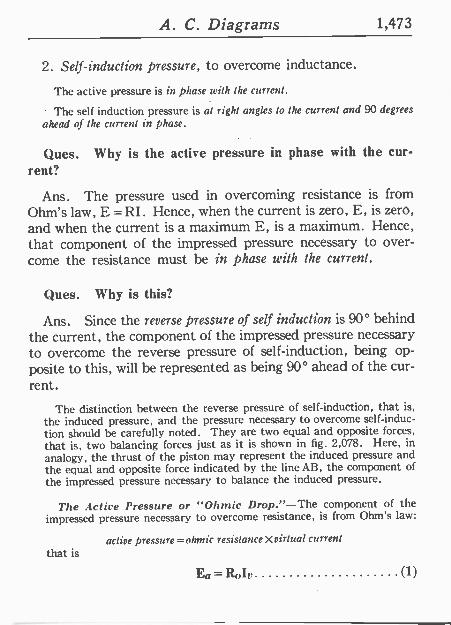
A. C. Diagrams 1,473
2. Self-induction pressure, to overcome inductance.
The active pressure is in phase with the current.
The self induction pressure is al right angles lo the current and 90 degrees
ahead of the current in phase.
Ques. Why is the active pressure in phase with the cur- rent?
Ans. The pressure used in overcoming resistance is from Ohm's law, E =RI. Hence, when the current is zero, E, is zero, and when the current is a maximum E, is a maximum. Hence, that component of the impressed pressure necessary to over- come the resistance must be in phase with the current.
Ques. Why is this?
Ans. Since the reverse pressure of self induction is 90° behind the current, the component of the impressed pressure necessary to overcome the reverse pressure of self-induction, being op- posite to this, will be rep-esented as being 90° ahead of the cur- rent.
The distinction between the reverse pressure of self-induction, that ís, the induced pressure, and the pressure necessary to overcome self-induc- tion should be carefully noted. They are two equal and opposite forces, that is, two balancing forces just as ít is shown ín fig. 2,078. Here, ín
analogy, the thrust of the piston may represent the induced pressure and the equal and opposite force indicated by the line AB, the component of the impressed pressure necessary to balance the induced pressure.
The Active Pressure or "Ohmic Drop/'-The component of the impressed pressure necessary to overcome resistance, ís from Ohm's law:
that is active pressure=ohmic resistanceXvirtual current
Ea = Roly (1)
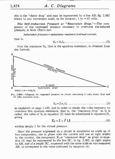
1,474 A. C. Diagrams
this is the "ohmic drop" and may be represented by a line AB, fig. 2,082 drawn to any convenient scale, as for instance, 1 in. =10 volts.
The Self -Induction Pressure or "Reactance Drop."-The com- ponent of the impressed pressure necessary to overcome the induced pressure, is from Ohm's law:
inductance pressure=inductance reactance Xvirtual current;
that is, Et = X1I, (2)
Now the reactance Xi, that is the spurious resistance, is obtained from the formula
A
ao /4/PA,
u
0
B REACTANCE SCALES L IN 4 VOLTS
DROP
FIG. 2,083.-Diagram for impressed pressure on circuit containing 5 volts ohmic drop and 15 volts reactance drop.
SL=27rf L (3)
as explained on page 1,420, and in order to obtain the volts necessary to overcome this spurious resistance, that is, the "reactance drop" as it is called, the value of Xi in equation (3) must be substituted in equation(2), giving
Ei =2 , f LI (4)
writing simply I for the virtual pressure.
Since the pressure impressed on a circuit is considered as made up of two components, one in phase with the current and one at right angles to the current, the component Et or "reactance drop" as given in equa- tion (4) may he represented by the line BC. in fig. 2.082, at right angles to AB, and of a length BC, measured with the same scale as was measured AB, to correspond to the value indicated by equation (4).
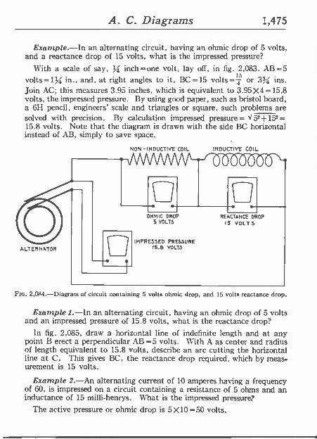
A. C. Diagrams 1,475
Example.-In an alternating circuit, having an ohmic drop of 5 volts, and a reactance drop of 15 volts, what is the impressed pressure?
With a scale of say, % inch=one volt, lay off, in fig. 2,083. AB=5 volts =1 Vi, in., and, at right angles to it, 13C =15 volts =11 or 3,1.< ins. Join AC; this measures 3.95 inches, which is equivalent to 3.95 X4 =15.8 volts, the impressed pressure. By using good paper, such as bristol board, a 6H pencil, engineers' scale and triangles or square, such problems are solved with precision. By calculation impressed pressure= X52+152= 15.8 volts. Note that the diagram is drawn with the side BC horizontal instead of AB, simply to save space.
ALTERNATOR
NON -INDUCTIVE COIL
OHMIC DROP 5 VOLTS
IMPRESSED PRESSURE 15.9 VOLTS
INDUCTIVE COIL
REACTANCE DROP I5 VOLTS
FIG. 2,O84.-Diagram of circuit containing 5 volts ohmic drop, and 15 volts reactance drop.
Example 1.-In an alternating circuit, having an ohmic drop of 5 volts and an impressed pressure of 15.8 volts, what is the reactance drop'
In fig. 2,085, draw a horizontal line of indefinite length and at any point B erect a perpendicular AB =5 volts. W-ith A as center and radius of length equivalent to 15.8 volts, describe an arc cutting the horizontal line at C. This gives BC, the reactance drop required, which by meas- urement is 15 volts.
Example 2.-An alternating current of 10 amperes having a frequency of 60, is impressed on a circuit containing a resistance of 5 ohms and an inductance of 15 milli -henrys. What is the impressed pressure?
The active pressure or ohmic drop is 5X10=50 X10 volts.
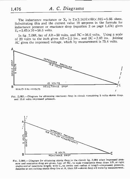
1,476 A. C. Diagrams
The inductance reactance or Xi is 2X3.1416X60X.015=5.66 ohms. Substituting this and the current value 10 amperes in the formula for
inductance pressure or reactance drop (equation 2 on page 1,474) gives Et =5.65X 10=56.5 volts.
In fig. 2,088, lap of AB=50 volts, and BC=56.6 volts. Using a scale
of 20 volts to the inch gives AB=2.5 ins., and BC=2.83 ins. Joining AC gives the impressed voltage, which by measurement is 75.4 volts.
A
a o ¢ o V
L o
B REACTANCE DROP SCALE: 1 IN. 4 VOLTS
/
I
C
Ftc. 2,085.-Diagram for obtaining reactance drop in circuit containing 5 volts ohmic drop.
and 15.8 volts impressed pressure.
C
FIG. 2,086.-Diagram for obtaining ohmic drop in the circuit fig. 2,084 when impressed pres-
sure and reactance drop are given. Lay off BC, to scale =reactance drop; draw AB, at right angles and of indefinite length; with C, as center and radius of length =impressed pressure,
describe an arc cutting ohmic drop line at A, then AB =ohmic drop =5 volts by measurement.
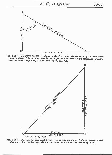
A. C. Diagrams 1,477
REACTANCE DROP c
Flo. 2,087.-Graphical method of finding angle of lag when the ohmic drop and reactance drop are given. The angle of lag 4,, is that angle included between the impressed pressure and the ohmic drop lines, that is, between AC and AB.
A OHMIC DROP B SCALE 1 IN.. 20 VOLTS
Fro. 2,088.-Diagram for impressed pressure on circuit containing 5 ohms resistance and inductance of 15 milli -henrys, the current being 10 amperes with frequency of 60.
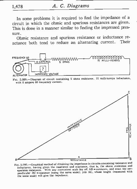
1,478 A. C. Diagrams
In some problems it is required to find the impedance of a circuit in which the ohmic and spurious resistances are given. This is done in a manner similar to finding the impressed pres-
sure. Ohmic resistance and spurious resistance or inductance re-
actance both tend to reduce an alternating current. Their
fREQUENCY CO
10 AMPERES
ALTERNATOR I IMPRESSED VOLTAGE
5 OIiMS I5 MILLI-IIENRYS
FIG. 2,089.-Diagram of circuit containing 5 ohms resistance, 15 milli -henrys inductance,
with 8 ampere 60 frequency current.
W
A RESISTANCE B
FIG. 2.090. --Graphical method of obtaining the impedance in circuits containing resistance and
inductance, having given the resistance and reactance, that is, the ohmic resistance and
spurious resistance. \Vith any convenient scale lay off All --resistance, and erect the per-
pendicular BC =reactance (using the same scale); join AC, whose length (measured with
the same scale) will give the impedance.
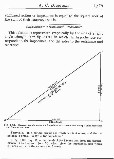
A. C. Diagrams 1,479
combined action or impedance is equal to the square root of the sum of their squares, that is,
impedance = J resistance' +reactance2
This relation is represented graphically by the side of a right angle triangle as in fig. 2,090, in which the hypothenuse cor- responds to the impedance, and the sides to the resistance and reactance.
A RESISTANCE FIG. 2,031.-Diagram for obtaining the impedance of a circuit containing 4 ohms resistance
and 3 ohms reactance.
Example.-In a certain circuit the resistance is 4 ohms, and the re- actance 3 ohms. What is the impedance'
In fig. 2,091, lay off, on any scale AB=4 ohms and erect the perpen- dicular BC =3 ohms. Join AC, which gives the impedance, and which is, measured with the same scale. 5 ohms.
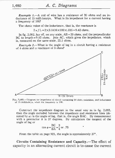
1,480 A. C. Diagrams
Example 1.-A coil of wire has a resistance of 20 ohms and an in- ductance of 15 milli -henrys. What is its impedance for a current having a frequency of 100?
The ohmic value of the inductance, that is, the reactance is
2irfL=2X3.1416X100X.015=9.42 ohms.
In fig. 2.092, lay off, on any scale, AB =20 ohms, and the perpendicular BC to length=9.42 ohms. Join AC, which gives the impedance, which is, measured on the same scale, 22.1 ohms.
Example 2.-What is the angle of lag in a circuit having a resistance of 4 ohms and a reactance of 3 ohms?
22.
A R-20 OHMS B
FIG. 2 092.-Diagram for impedance of circuit containing 20 ohms resistance, and inductance of 15 millihenrys, when the frequency is 100.
Construct the impedance diagram in the usual way as in fig. 2,093, then the angle included between the impedance and resistance lines (de- noted by 66) is the angle of lag, that is. the angle BAC. By measurement with a protractor it is 37 degrees. By calculation the tangent of the angle of lag or
tan 4._ =-4
or .75
From the table on page 921, the angle is approximately 37°.
Circuits Containing Resistance and Capacity.-The effect of capacity in an alternating current circuit is to cause the current
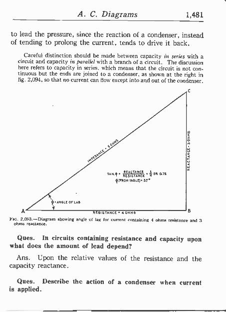
A. C. Diagrams 1,481
to lead the pressure, since the reaction of a condenser, instead of tending to prolong the current, tends to drive it back.
Careful distinction should he made between capacity in series with a circuit and capacity in parallel with a branch of a circuit. The discussion here refers to capacity in series, which means that the circuit is not con- tinuous but the ends are joined to a condenser, as shown at the right in fig. 2,094, so that no current can flow except into and out of the condenser.
c
PEACTANCE S TAN.q
RESISTANCE 4 OR 0.75
4(rROM TABLE) 37°
A RESISTANCE 4OHMS B
2,093.-Diagram showing angle of lag for current containing 4 ohms resistance and 3 ohms reactance.
Ques. In circuits containing resistance and capacity upon what does the amount of lead depend?
Ans. Upon the relative values of the resistance and the capacity reactance.
Ques. Describe the action of a condenser when current is applied.
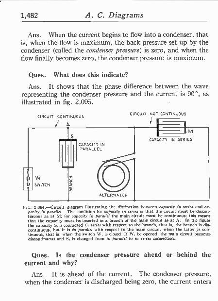
1,482 A. C. Diagrams
Ans. When the current begins to flow into a condenser, that is, when the flow is maximum, the back pressure set up by the condenser (called the condenser pressure) is zero, and when the flow finally becomes zero, the condenser pressure is maximum.
Ques. What does this indicate?
Ans. It shows that the phase difference between the wave representing the condenser pressure and the current is 90°, as illustrated in fig. 2,095.
o
i
CIRCUIT CONTINUOUS
W SWITCH
_ u
CAPACITY IN PARALLEL
ALTERNATOR
CIRCUIT NOT CONTINUOUS
1
M CAPACITY IN SERIES
FIG. 2,094.-Circuit diagram illustrating the distinction between capacity in series and ca pacify in parallel. The condition for capacity in series is that the circuit must be discon tinuous as at M; for capacity in parallel the main circuit must he continuous; this means that the capacity must be inserted in a branch of the main circuit as at A. In the figure the capacity S, is connected in series with respect to the branch, that is, the branch is dis- continuous, but it is of parallel with respect to the main circuit, when the latter is con- tinuous, that is, when the switch W, is closed. If W. be opened, the main circuit becomes discontinuous and S. is changed from in parallel to in series connection.
Ques. Is the condenser pressure ahead or behind the current and why?
Ans. It is ahead of the current. The condenser pressure, when the condenser is discharged being zero, the current enters
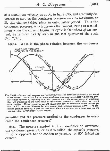
A. C. Diagrams 1,483
at a maximum velocity as at A, in fig. 2,095, and gradually de- creases to zero as the condenser pressure rises to maximum at B, this change taking place in one -quarter period. Thus the condenser pressure, which opposes the current, being at a maxi- mum when the current begins its cycle is 90° ahead of the cur- rent, as is more clearly seen in the last quarter of the cycle (fig. 2,095) .
Ques. What is the phase relation between the condenser
CONDENSER PRESSURE 90°AHEAD OF THE CURRENT
CUD tit
.. CON
Flo. 2,095.-Current and pressure curves showing that the condenser pressure is 90° ahead of the current. A current flowing into a condenser encounters a gradually increasing pres- sure which opposes it, beginning from zero pressure when the current enters at maximum flow and increasing to the same value as the current pressure, at which time the current ceases to flow. Hence, since the current varies from zero to maximum in one quarter pe- riod, or 90°, the phase difference between current and condenser pressure is 90°. The con- denser pressure reaching a positive maximum when the current starts from zero on the positive wave, is 90° ahead of the current.
pressure and the pressure applied to the condenser to over- come the condenser pressure?
Ans. The pressure applied to the condenser to overcome the condenser pressure, or as it is called, the capacity pressure, must be opposite to the condenser pressure, or 90° behind the
current.
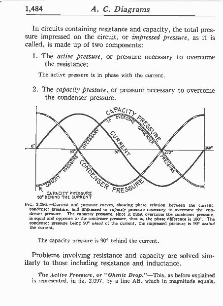
1,484 A. C. Diagrams
In circuits containing resistance and capacity, the total pres- sure impressed on the circuit, or impressed pressure, as it is called, is made up of two components:
1. The active pressure, or pressure necessary to overcome the resistance;
The active pressure is in phase with the current.
2. The capacity pressure, or pressure necessary to overcome the condenser pressure.
p,PAC/
CAPACITY PRESSURE 90° BEHIND THE CURRENT
Ftc. 2,096.-Current and pressure curves, showing phase relation between the current, condenser pressure, and impressed or rapacity pressure necessary to overcome the con- denser pressure. The capacity pressure, since it must overcome the condenser pressure, is equal and opposite to the condenser pressure, that is, the phase difference is 180°. The condenser pressure being 90° ahead of the current, the impressed pressure is 90° behind the current.
A
360°
/1/45,FR
PRESS.
The capacity pressure is 90° behind the current.
Problems involving resistance and capacity are solved sim- ilarly to those including resistance and inductance.
The Active Pressure, or "Ohmic Drop."-This, as before explained is represented, in fig. 2,097, by a line AB, which in magnitude equals,
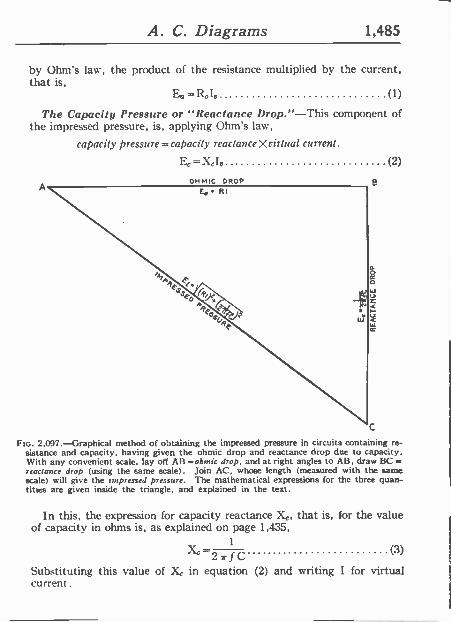
A. C. Diagrams 1,485
by Ohm's law, the product of the resistance multiplied by the current, that is,
Ea=1tIo (1)
The Capacity Pressure or "Reactance Drop."-This component of the impressed pressure, is, applying Ohm's law,
capacity pressure =capacity reactanceXrirtnal current.
E,=410 (2)
C
FIG. 2,097.-Graphical method of obtaining the impressed pressure in circuits containing re- sistance and capacity, having given the ohmic drop and reactance drop due to capacity. With any convenient scale, lay off AB =ohrnic drop, and at right angles to AB, draw BC =-
reactance drop (using the same scale). Join AC, whose length (measured with the same scale) will give the tmpressed pressure. The mathematical expressions for the three quan- tities are given inside the triangle, and explained in the text.
In this, the expression for capacity reactance Xe, that is, for the value of capacity in ohms is, as explained on page 1,435,
1
` 2rrfC Substituting this value of Xe in equation (2) and writing I for virtual current.
(3)
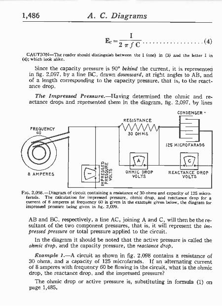
1,486 A. C. Diagrams
I Ec
2 7- f C (4)
CAUTION-The reader should distinguish between the 1 (one) in (3) and the letter I in (4); which look alike.
Since the capacity pressure is 90° behind the current, it is represented in fig. 2,097, by a line BC, drawn downward, at right angles to AB, and of a length corresponding to the capacity pressure, that is, to the react- ance drop.
The Impressed Pressure.-Having determined the ohmic and re- actance drops and represented them in the diagram, fig. 2,097, by lines
CONDENSER
FREQUENCY 60
8 AMPERES
RESISTANCE
30 OHMS
125 MICRO FARADS
OHMIC DROP REACTANCE DROP VOLTS VOLTS
FIG. 2,098.-Diagram of circuit containing a resistance of 30 ohms and capacity of 125 micro - farads. The calculation for impressed pressure, ohmic drop, and reactance drop for a current of 8 amperes at frequency 60 is given in the example given below, the diagram for impressed pressure being given in fig. 2,099.
AB and BC, respectively, a line AC, joining A and C, will then he the re- sultant of the two component pressures, that is, it will represent the im- pressed pressure or total pressure applied to the circuit.
In the diagram it should be noted that the active pressure is called the ohmic drop, and the capacity pressure, the reactance drop.
Example 1.-A circuit as shown in fig. 2,098 contains a resistance of 30 ohms, and a capacity of 125 microfarads. If an alternating current of 8 amperes with frequency 60 be flowing in the circuit, what is the ohmic drop, the reactance drop, and the impressed pressure?
The ohmic drop or active pressure is, substituting in formula (1) on page 1,485,

A. C. Diagrams 1,487
Ea = 30 X 8 = 240 volts
which is the reading of voltmeter A in fig. 2,098.
The reactance drop or
8
E` 2 r J C 2 x3 .1416 X 60x .000125 -170 volts
in substituting, note that the capacity C of 125 microfarads is reduced to .000125 farad.
Using a scale of say 1 inch=80 volts, lay off in fig. 2,099, AB, equal to the ohmic drop of 240 volts; on this scale AB=3 inches. Lay off at
OHMIC DROP 240 VOLTS
240=80.a"
cFLfqO
`3Sio
MA>, Ae} 6,F 'ea .44, RF
29v Mt.
bGALE : l"= 80 VOLTS 1-s(7. ,4 l
B
C
Flo. 2,099.-Diagram for obtaining the impressed pressure of the circuit shown in fig. 2,098.
right angles, BC = reactance drop =170 volts = 2.125 inches. Join AC, which gives the impressed voltage (that is the reading of volt meter I in fig. 2,098), which measures 294 volts.
By calculation, impressed pressure= 2402+1702=294 volts.
Example 2.-In the circuit shown in fig. 2,098, what is the angle of lead?
The tangent of the angle of lead is given by the quotient of the reactance divided by the resistance of the circuit. That is,
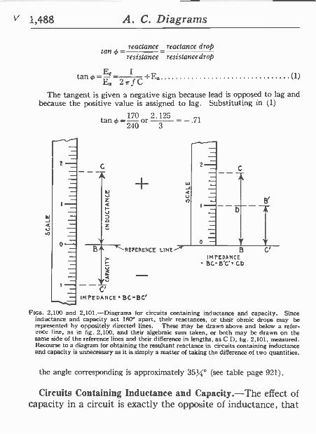
V 1,488 A. C. Diagrams
reactance reactance drop tan4,_ -
resistance resistance drop
tan -E`- 1 : Ea (1) Ea 2 r f C
The tangent is given a negative sign because lead is opposed to lag and because the positive value is assigned to lag. Substituting in (1)
tan 4.=70 2.125 240 3
2 -
o
C -- 1 -J
ItJ Q V
á I- V
Z
v BA ..1-*" REFERENCE LINE-"e'r
vú C'
IMPEDANCE BC -BC'
B'
B C'
IMPEDANCE BC-B'C CD
FIGS. 2,100 and 2,101.-Diagrams for circuits containing inductance and capacity. Since inductance and capacity act 1800 apart, their reactances, or their ohmic drops may be represented by oppositely directed lines. These may be drawn above and below a refer- ence line, as in fig. 2,100, and their algebraic sum taken, or both may be drawn on the same side of the reference lines and their difference in lengths, as C D, fig. 2,101, measured. Recourse to a diagram for obtaining the resultant reactance in circuits containing inductance and capacity is unnecessary as it is simply a matter of taking the difference of two quantities.
the angle corresponding is approximately 35%° (see table page 921).
Circuits Containing Inductance and Capacity.-The effect of capacity in a circuit is exactly the opposite of inductance, that
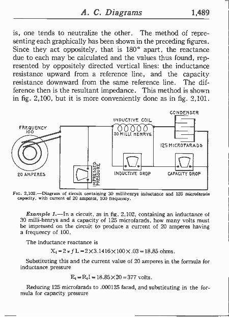
A. C. Diagrams 1,489
is, one tends to neutralize the other. The method of repre- senting each graphically has been shown in the preceding figures. Since they act oppositely, that is 180° apart, the reactance due to each may be calculated and the values thus found, rep- resented by oppositely directed vertical lines: the inductance resistance upward from a reference line, and the capacity resistance downward from the same reference line. The dif- ference then is the resultant impedance. This method is shown in fig. 2,100, but it is more conveniently done as in fig. 2,101.
FREQUENCY 100
20 AMPERES
INDUCTIVE COIL
30 MILLI HENRYS
CONDENSER
125 MICROFAP,ADS 0. INDUCTIVE DROP CAPACITY DROP
FIG. 2,102.-Diagram of circuit containing 30 millihenrys inductance and 125 microfarads capacity, with current of 20 amperes, 100 frequency.
Example 1.-In a circuit, as in fig. 2,102, containing an inductance of 30 milli -henrys and a capacity of 125 microfarads, how many volts must be impressed on the circuit to produce a current of 20 amperes having a frequency of 100.
The inductance reactance. is
X,=2irfL=2X3.1416X100X.03=18.85ohms.
Substituting this and the current value of 20 amperes in the formula for inductance pressure
Et = R,I =18.85 X 20 = 377 volts.
Reducing 125 microfarads to .000125 farad, and substituting in the for- mula for capacity pressure
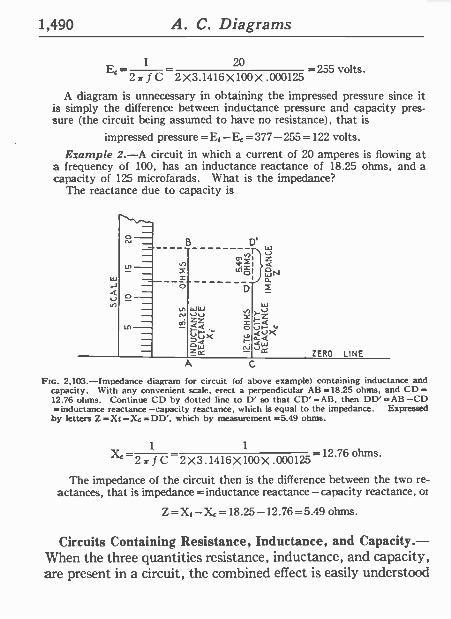
1,490 A. C. Diagrams
20 E` 27r f C 2 X3.1416 X100 X .000125
-255 volts.
A diagram is unnecessary in obtaining the impressed pressure since it is simply the difference between inductance pressure and capacity pres- sure (the circuit being assumed to have no resistance), that is
impressed pressure =E1-Ec =377-255 =122 volts.
Example 2.-A circuit in which a current of 20 amperes is flowing at a frequency of 100, has an inductance reactance of 18.25 ohms, and a capacity of 125 microfarads. What is the impedance?
The reactance due to capacity is
.._ B
m =i `nl D
w
á WN
tn
w -J 4
v
CC;
ww VV á¿ jQX
f w
Fz
Zrt N V ZERO LINE
A C
Ftc. 2,103.-1mpedance diagram for circuit (of above example) containing inductance and capacity. With any convenient scale, erect a perpendicular AB =18.25 ohms, and CD =-
12.76 ohms. Continue CD by dotted line to D' so that CD' =All, then DD' =AB-CD =inductance reactance-capacity reactance, which is equal to the impedance. Expressed
by letters Z=Xt-Xc=DD', which by measurement =5.49 ohms.
1 1 X` -27r f C 2X3 .1416 X 100 X .000125 -12.76 ohms.
The impedance of the circuit then is the difference between the two re- actances, that is impedance =inductance reactance-capacity reactance, or
Z=Xt-X,=18.25-12.76=5.49 ohms.
Circuits Containing Resistance, Inductance, and Capacity.- When the three quantities resistance, inductance, and capacity, are present in a circuit, the combined effect is easily understood
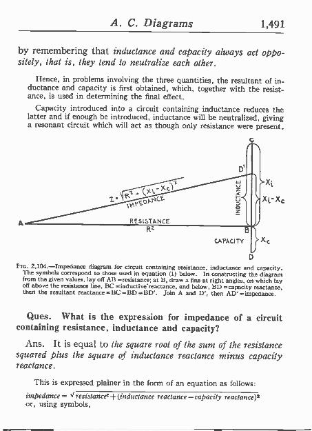
A. C. Diagrams 1,491
by remembering that inductance and capacity always act oppo- sitely, that is, they tend to neutralize each other.
Hence, in problems involving the three quantities, the resultant of in- ductance and capacity is first obtained, which, together with the resist- ance, is used in determining the final effect.
Capacity introduced into a circuit containing inductance reduces the latter and if enough be introduced, inductance will be neutralized, giving a resonant circuit which will act as though only resistance were present.
G
D
FIG. 2,I04.-Impedance diagram for circuit containing resistance, inductance and capacity.. The symbols correspond to those used in equation (1) below. In constructing the diagram from the given values, lay off AB =resistance; at B, draw a line at right angles, on which lay off above the resistance line, BC =inductive reactance, and below, BD =capacity reactance. then the resultant reactance =BC -BD =BD'. Join A and D', then AD' =impedance.
Ques. What is the expression for impedance of a circuit containing resistance, inductance and capacity?
Ans. It is equal to the square root of the sum of the resistance squared plus the square of inductance reactance minus capacity reactance.
This is expressed plainer in the form of an equation as follows:
impedance= Vresistance2+(inductance reactance-capacity reactance)2 or, using symbols,
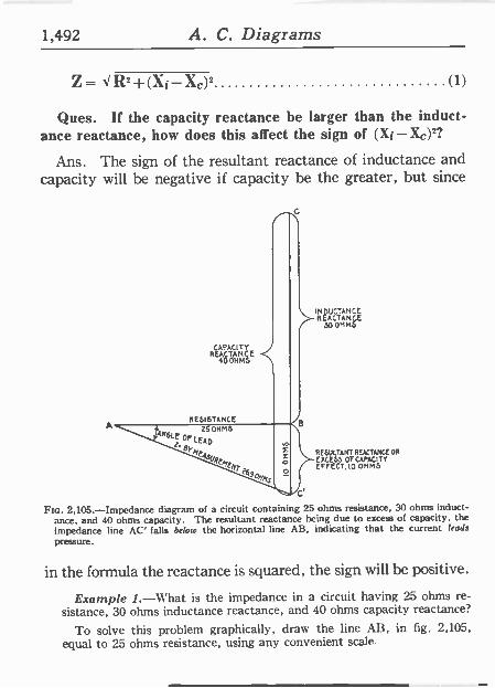
1,492 A. C. Diagrams
Z- dR2+ (Xi -XC)2 (1)
Ques. If the capacity reactance be larger than the induct- ance reactance, how does this affect the sign of (Xi- Xá)2?
Ans. The sign of the resultant reactance of inductance and capacity will be negative if capacity be the greater, but since
CAPACITY REACT
4 HMCSE
RESISTANCE
INDUCTANCE REA
30 OHMCTANSL
RESULTANT REACTANCE OR
EXCESS Or CAPACITY EFFECT, 1O OHMS
Fte. 2,105.-Impedance diagram of a circuit containing 25 ohms resistance, 30 ohms induct- ance, and 40 ohms capacity. The resultant reactance being due to excess of capacity, the impedance line AC' falls below the horizontal line AB, indicating that the current leads
pressure.
in the formula the reactance is squared, the sign will be positive.
Example 1.-What is the impedance in a circuit having 25 ohms re- sistance, 30 ohms inductance reactance, and 40 ohms capacity reactance?
To solve this problem graphically, draw the line AB, in fig. 2,105, equal to 25 ohms resistance, using any convenient scale.
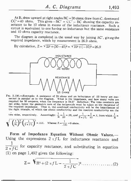
A. C. Diagrams 1,493
At B, draw upward at right angles BC = 30 ohms; draw from C, downward CC' =40 ohms. This gives-BC' = CC' - BC showing the capacity re- actance to he 10 ohms in excess of the inductance reactance. Such a circuit is equivalent to one having no inductance but the same resistance and 10 ohms capacity reactance.
The diagram is completed in the usual way by joining AC', giving the required impedance, which by measurement is 26.9 ohms.
By calculation, Z= X252+(30-40)2= X252+(-10)2=26.9
INDUCTANCE
$O. .02 %ENR7
RESISTANCE
20 0NM5 Fro. 2,106.-Example: A resistance of 20 ohms and an inductance of .02 henry are con-
nected in parallel as in the diagram. 11 hat is the impedance, and how many volts are required for 50 amperes, when the frequency is 78.6? Solution: The time constants are not alike, hence the geometric sum of the reciprocals must be taken as the reciprocal of the required impedance. That is, the combined conductivity will he the hypothenuse of the right triangle, of which the ohmic conductivity and the reactive conductivity are the
two sides, respectively. Accordingly: -t 20 =.05, and
2 !-_ 10 .1, from which- =
.11 i +(2 IJL/ -.111. Whence Z
3.111 =9 ohms.
Form of Impedance Equation Without Ohmic Values.- Using the expressions 2 =f L for inductance reactance and
1
2 for capacity reactance, and substituting in equation
(1) on page 1,492 gives the following:
Z= 1/R2+(2 f L fC )2 (2)
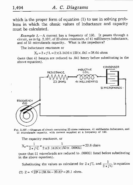
1,494 A. C. Diagrams
CONDENSER
which is the proper form of equation (1) to use in solving prob- lems in which the ohmic values of inductance and capacity must be calculated.
Example 1.-A current has a frequency of 150. It passes through a circuit, as in fig. 2,107, of 23 ohms resistance, of 41 millihenrys inductance, and of 51 microfarads capacity. What is the impedance?
The inductance reactance or
Xt=2trfL=2 X3.1416 X150 X.041=38.64 ohms
(note that 41 henrys are reduced to .041 henry before substituting in the above equation).
RESISTANCE. INDUCTIVE
COIL
rte. 2,107.-Diagram of circuit containing 23 ohms resistance, 41 millihenrys inductance, and
51 microfarads capacity, with current supplied at a frequency of 150.
The capacity reactance, or
1 1 -20.8 ohms Xe 2 r f C 2 X3 .1416 X 150 X. 000051
(note that 51 microfarads are reduced to .000051 farad before substituting in the above equation).
Substituting the values as calculated for 2 f L and 1
i an equation
(2) Z= X232 -F(38.64-20.8)2=29.1 ohms.
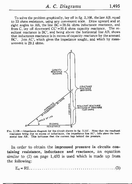
A. C. Diagrams 1,495
To solve the problem graphically, lay off in fig. 2,108, the line AB, equal to 23 ohms resistance, using any convenient scale. Draw upward and at right angles to AB, the line BC =38.64 ohms inductance reactance, and from C, lay off downward CC' = 20.8 ohms capacity reactance. The re- sultant reactance is BC', and being above the horizontal line AB, shows that inductance reactance is in excess of capacity reactance by the amount BC'. Join AC', which gives the impedance sought, and which by meas- urement is 29.1 ohms.
4.9'
A RESISTANCE
Ftc. 2,108.-Impedance diagram for the circuit shown in fig. 2,107. Note that the resultant reactance being due to excess of inductance, the impedance line AC', falls above the hori- zontal line AB. This indicates that the current lags behind the pressure.
CAPACITY REACTANCE
?OP OHMS
INDUCTANCE REACTANCE 3864 OHMS
RESJLTANT REACTANCE OR EXCESS OF INDUCTANCE
r7.84 OHMS
In order to obtain the impressed pressure in circuits con- taining resistance, inductance and reactance, an equation similar to (2) on page 1,493 is used which is made up from the following:
Eo =RI (3)
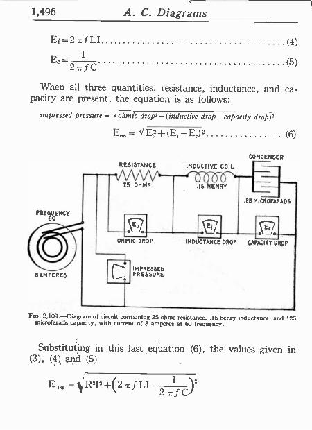
1,496 A. C. Diagrams
Ei = 2 7c f LI (4)
E,- I (5) 2 C
When all three quantities, resistance, inductance, and ca- pacity are present, the equation is as follows:
impressed pressure= < ohmic drop2+(inductive drop-capacity drop),
FREQ6UOENCY
8 AMPERES
E,,,, _ < El +(E,-E,) 2 (6)
AMRESIIS/TAN/CE/
V V 25 OHMS
IMPRESSED PRESSURE
CONDENSER
INDUCTIVE COIL
IS HENRY
I25.MICROFARAD6
Ec . INDUCTANCE DROP CAPACITY DROP
FIG. 2,109.-Diagram of circuit containing 25 ohms resistance, .15 henry inductance, *and 125 microfarads capacity, with current of 8 amperes at 60 frequency.
Substituting in this last equation (6), the values given in (3)9 (4) and (5)
E = R2I2
+(2 f LI I )2
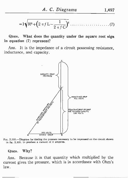
A. C. Diagrams 1,497
= IRZ +(2 z f L I lZ 2-fC (7)
Ques. What does the quantity under the square root sign in equation (7) represent?
Ans. It is the impedance of a circuit possessing resistance, inductance, and capacity.
CAPACITY DROP 170 VOLTS
Q
A OHMIC DROP B
\.,_IUDUCIANCE DROP 952 VOLTS
RESULTANT DROP OR DROP DUE TO EXCESS CAPACITY.
282 VOLTS
FIG. 2,110.-Diagram for finding the pressure necessary to he impressed on the circuit shown in fig. 2,109, to produce a current of 8 amperes.
Ques. Why? -
Ans. Because it is that quantity which multiplied by the current gives the pressure, which is in accordance with Ohm's law.
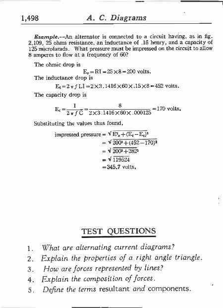
1,498 A. C. Diagrams
Example.-An alternator is connected to a circuit having, as in fig. 2,109, 25 ohms resistance, an inductance of .15 henry, and a capacity of 125 microfarads. What pressure must be impressed on the circuit to allow 8 amperes to flow at a frequency of 60?
The ohmic drop is Eo = RI =25X8=200 volts.
The inductance drop is
Et=2TfLI=2X3.1416X60X.15X8=452 volts.
The capacity drop is
I 8
E` 2 Ir f C 2X3.1416 x 60 X .000125
Substituting the values thus found,
impressed pressure = v Ego + (E, - E,)2
-170 volts.
= <2002+(452-170)2
= r 2002+2822
= < 119524 =345.7 volts.
TEST QUESTIONS
1. What are alternating current diagrams?
2. Explain the properties of a right angle triangle.
3. How are forces represented by lines?
4. Explain the composition of forces.
5. Define the terms resultant and components.
A. C. Diagrams 1,499
6. In circuits containing resistance and inductance what two components make up the impressed pres- sure?
7. Why is the active pressure in phase with the current? 8. In circuits containing resistance and capacity upon
what does the amount of lead depend? 9. Describe the action of a condenser when current is
applied. 10. Is the condenser pressure ahead or behind the cur-
rent, and why? 11. What is the phase relation between the condenser
pressure and the pressure applied to the condenser to overcome the condenser pressure?
12. Name the two components which make up the im- pressed pressure in circuits containing resistance and capacity.
13. How is the inductance reactance found in circuits containing inductance and capacity?
14. Is a diagram necessary to obtain the impressed pres- sure?
15. What is the expression for impedance of a circuit containing resistance, inductance and capacity?
16. If the capacity reactance be larger than the induct- ance reactance, how does this affect the sign of (Xi -X,)2?
17. Give the form of impedance equation without ohmic values.
18. When all three quantities, resistance, inductance and capacity, are present, what is the equation for the impressed pressure?
1,500 A. C. Diagrams
19. What does the quantity under the square root sign in the equation for impressed pressure, represent?
20. Give the examples, for the various circuits.
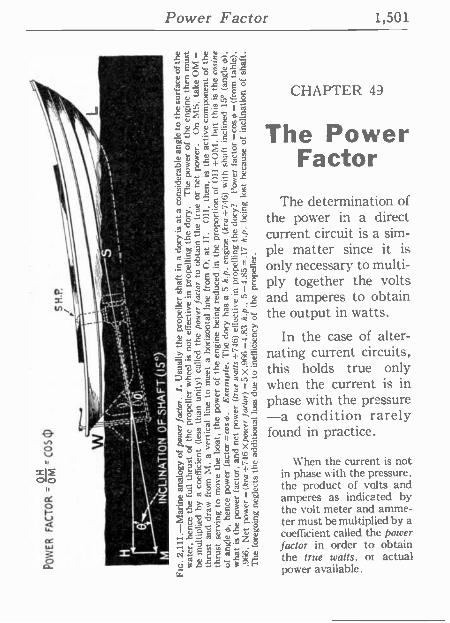
Power Factor 1,501
1q os °: 7 fi" .^e^y..
°I CD O m
u m m°csE`o .. »..ip
CCp
^ N . C
ló C 0. .r up^Vi E
m., till -52.28-51-0..2.
1.011'11111 The Power er r> ig1°H2 Factor
. 2v'^tú, :O u u .Q = 3
C C Y O .+
$FO,,,OtOS h . m The determination of '1 _ .i".. - a 1.` ,.c
a , ° Ü c g ó the power in a direct ; ' L= __tv
current circuit is a sim- 1
0 ". O C.., -2111°' _ ple matter since it is A -a c_
.__ 1 ó .e ó only necessary to multi-
s ; 1 Qe 1 ply together the volts 11 _ ' - ' ' J-9.1.11., C N a _ ,1,:,2. ,u _ and amperes to obtain
r .
g 1F = r = the output in watts. otC_-a= gI c c' ú r . = -5:±:°q v In the case of alter- O- ó.éo II u é ...t..11 -:5r---`7.$ v nating current clrcults, u n c o- ra .
,,; ]^ ª X 2 this holds true only " ,..13;211 = ',..¡Z1 v when the current is in . :i Q k
--1. 8
l g phase with the pressure 412 $, -a condition rarely
6 11 ., o
ñ
8 3 found in practice.
ó 3. ó X.
V . `p c $ ó.oI ñ
z L A º When the current is not =IF ` ° ° ó o in phase with the pressure. o
: -3 - 1 ó °
a ? : the product of volts and U a_g Im ó °¡:? 11.É121111 v amperes as indicated by the volt meter and amme-
á o z ; s á c ter must be multiplied by a
r ª Á d ñ z d coefficient called the power 4+ ° -9... H " factor in order to obtain ó _ O7 ro
E ' 2 1° r g x the true watts, or actual d 61.1-5. Ó i .E. power available.
CHAPTER 49
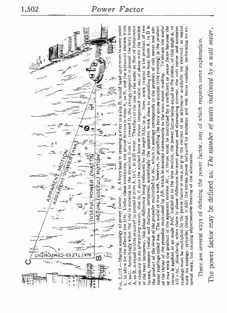
u i
, (
nl
I ?.
A
.
. ;
I, 11
1!
, ,,1
PI
,,
l,
yi
II
1 a
u
um,
l I
/' I
I
( \
I
4
43,:,
glF
n 1
td
I
; N
T i
MpT
I I
W
t,Í: ,
i ¡pw
FR
1
'
.,11,
11
, h lk
l'gf'
\k\,
r \
, sy
/¡
k` \
1 \\
It!
t 10
'1
11
`\ I\\
`I
I U
SE
FU
I: O
WE
R
WA
7y
I t
ryrl
Z
B
I Q
A
TU
AL
USE
U
L M
pTIO
N _
II
If:1
)1
.',
,, (
t
,. ,.
, ,,.
,
.! . ,n.
! U
UA
If
Fla
. 2,
112.
-Mar
ine
anal
ogy
of p
ower
fac
tor.
2.
A
fer
ry b
oat i
n cr
ossi
ng a
riv
er t
o a
slip
B,
wou
ld h
ead
up s
trea
m t
o so
me
poin
t C
, to
allo
w f
or th
e ef
fect
of
the
tide.
U
nder
the
se c
ondi
tions
, th
e ac
tual
mot
ion
is f
rom
A.
to 1
3, an
d th
e ap
pare
nt
mot
ion
from
A
, to
C.
Acc
ordi
ngly
whe
n th
e tid
e is
ru
nnin
g in
the
dire
ctio
n fr
om C
, to
war
d B
, th
e en
ergy
req
uire
d to
pro
pel
the
ferr
y fr
om
A,
to B
, is
equ
al t
o th
at re
quire
d to
pro
pel it
from
A,
to C
, in
stil
l w
ater
. T
he e
ffect
of t
he t
ide
is t
he s
ame
as t
hat o
f in
duct
ance
or
cap
acity
in
an a
ltern
atin
g ci
rcui
t, th
at is
, it
puts
the
app
lied
forc
e or
thr
ust
(impr
esse
d vo
lts)
out
of p
hase
with
the
mot
ion
of t
he b
oat
(am
pere
s),
this
pha
se d
iffer
ence
bei
ng in
dica
ted
by t
he a
ngle
BA
C o
r st
t. N
ow,
wor
k (w
atts
) is
the
pro
duct
of
two
fact
ors,
pr
essu
re
(vol
ts)
and
dist
ance
(am
pere
s);
acco
rdin
gly
the
appa
rent
wor
k do
ne in
pro
pelli
ng t
he
boat
fro
m A
, to
B i
s
the
prod
uct
of t
he th
rust
of
the
prop
elle
r m
ultip
lied
by A
C,
whi
ch in
ana
logy
cor
resp
onds
to th
e pr
oduc
t of
volt
met
er a
nd a
m-
met
er r
eadi
ngs
calle
d ke
a.
The
use
ful o
r tr
ue w
ork,
how
ever
, in
pro
pelli
ng t
he f
erry
acr
oss
stre
am (
tide
runn
ing)
is
the
prod
uct
of t
he th
rust
of
the
prop
elle
r m
ultip
lied
by A
B,
whi
ch i
n an
alog
y co
rres
pond
s to
the
wat
t met
er r
eadi
ng.
To
obta
in t
he u
sefu
l or
tru
e w
ork
the
prod
uct
of t
he a
ppar
ent
mot
ion
AC
, X
thr
ust
mus
t be
m
ultip
lied
by a
co
effic
ient
or
pow
er f
acto
r be
caus
e th
e th
rust
is
appl
ied
at a
n an
gle
BA
C (
calle
d 45
) to
the
tru
e m
otio
n, t
he p
ower
fac
tor
bein
g eq
ual
to t
he c
osin
e, o
f th
is a
ngle
0,
or
AB
-A
C.
Sim
ilarly
, w
hen
ther
e is
ph
ase
diffe
renc
e be
twee
n pr
essu
re a
nd a
ltern
atin
g cu
rren
t, th
e vo
lt m
eter
an
d am
met
er
read
ings
mus
t be
mul
tiplie
d by
the
pow
er f
acto
r or
cos
0, t
o gi
ve t
he
outp
ut o
f an
alte
rnat
or a
vaila
ble
for
exte
rnal
, or
use
ful
wor
k (i
n an
alog
y, p
rope
ller
thru
st
X A
B)
the
exce
ss p
ower
indi
cate
d by
am
met
er a
nd v
olt
met
er r
eadi
ngs,
per
form
ing
no e
x-
tern
al w
ork,
but
cau
sing
obj
ectio
nabl
e he
atin
g of
the
alte
rnat
or.
The
re a
re s
ever
al w
ays
of d
efin
ing
the
pow
er f
acto
r, a
ny o
f w
hich
re
quir
es s
ome
expl
anat
ion.
The
pow
er f
acto
r m
ay b
e de
fine
d as
: T
he n
umbe
r of
wat
ts i
ndic
ated
by
a w
att
met
er,
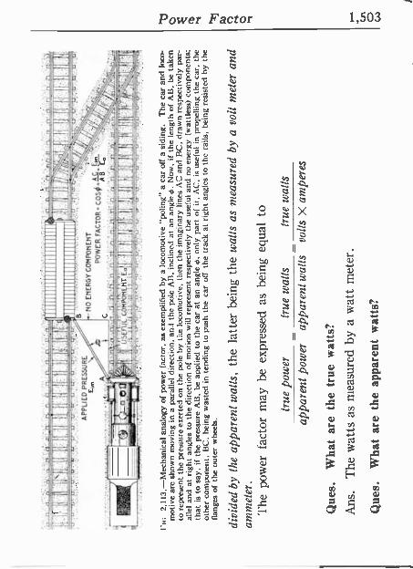
- "
' "
IIII
IIII
IIII
IIII
IIII
IIIE
1
1111
1111
1111
1111
1111
1111
1111
1111
111
~~~1
111_
111/
Wn
116I
IÍi
JI11
1111
1111
1111
1111
1111
1 .
, .
.
AP
PLI
ED
P
RE
SS
UR
E
EN
ER
GY
CO
MP
ON
EN
T
411,
C,
PO
WE
R
PIP
-1:IP
l
;nut
& c
ompo
nEnT
M
illi_
M
atti:
Mt
, ,
fi
i In
2,
113.
-Mec
hani
cal a
nalo
gy o
f po
wer
fact
or,
as e
xem
plifi
ed b
y a
loco
mot
ive
"pol
ing"
a c
ar o
ff a
sidi
ng.
The
car
and
loc
o-
mot
ive
are
show
n m
ovin
g in
a p
aral
lel di
rect
ion,
and
th
e po
le A
B,
incl
ined
at
an a
ngle
0.
Now
, if
the
leng
th o
f AB
, be
tak
en
to r
epre
sent
the
pre
ssur
e ex
erte
d on
the
pol
e by
the
loc
omot
ive,
the
n th
e im
agin
ary
lines
AC
and
BC
, dr
awn
resp
ectiv
ely
par-
al
lel
and
at r
ight
ang
les
to th
e di
rect
ion
of m
otio
n w
ill r
epre
sent
res
pect
ivel
y th
e us
eful
and
no
ener
gy
(wat
tless
) co
mpo
nent
s;
that
is
to s
ay,
if th
e pr
essu
re A
B,
be ap
plie
d to
the
car
at
an a
ngle
0,
only
pa
rt o
f it.
AC
, is
use
ful
in
prop
ellin
g th
e ca
r, t
he
othe
r co
mpo
nent
, BC
, be
ing
was
ted
in t
endi
ng t
o pu
sh t
he
car
off
the
trac
k at
rig
ht a
ngle
s to
the
rai
ls,
bein
g re
sist
ed b
y th
e
flang
es o
f th
e ou
ter
whe
els.
divi
ded
by t
he a
ppar
ent w
alls
, th
e la
tter
bein
g th
e w
alls
as
mea
sure
d by
a v
olt
met
er a
nd
amm
eter
. T
he p
ower
fac
tor
may
be
ex
pres
sed
as b
eing
eq
ual
to
true
pow
er
true
wal
ls
true
wat
ts
appa
rent
pow
er
appa
rent
wal
ls
volts
X a
mpe
res
Que
s.
Wha
t ar
e th
e tr
ue
wat
ts?
Ans
. T
he w
atts
as
mea
sure
d by
a w
att
met
er.
Que
s.
Wha
t ar
e th
e ap
pare
nt w
atts
?
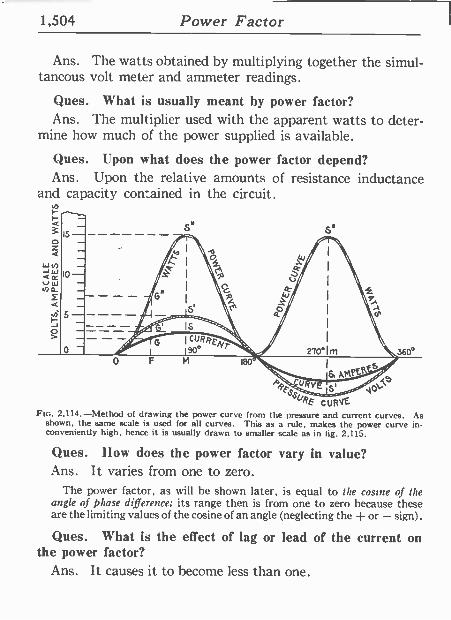
1,504 Power Factor
Ans. The watts obtained by multiplying together the simul- taneous volt meter and ammeter readings.
Ques. What is usually meant by power factor? Ans. The multiplier used with the apparent watts to deter-
mine how much of the power supplied is available.
Ques. Upon what does the power factor depend? Ans. Upon the relative amounts of resistance inductance
and capacity contained in the circuit.
o Z b \N Q
< 3 c; kJ ill 10 n-^
C. L `` 9
J
160
O
A
SURE CURE FIG. 2,114.-Method of drawing the power curve from the pressure and current curves. As
shown, the same scale is used for all curves. This as a rule, makes the power curve in- conveniently high, hence it is usually drawn to smaller scale as in 1ig. 2,115.
360°
Ques. Ilow does the power factor vary in value? Ans. It varies from one to zero.
The power factor, as will he shown later, is equal to the cosine of the angle of phase difference; its range then is from one to zero because these are the limiting values of the cosine of an angle (neglecting the + or - sign) .
Ques. What is the effect of lag or lead of the current on the power factor?
Ans. It causes it to become less than one.
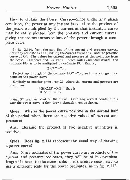
Power Factor 1,505
How to Obtain the Power Curve.-Since under any phase condition, the power at any instant is equal to the product of the pressure multiplied by the current at that instant, a curve may be easily plotted from the pressure and current curves, giving the instantaneous values of the power through a com- plete cycle.
In fig. 2,114, from the zero line of the current and pressure curves, draw any ordinate as at F, cutting the current curve at G, and the pressure curve at G'. The values for current and pressure at this point are from the scale, 2 amperes and 3.7 volts. Since watts =amperesXvolts, the ordinate FG, is to be multiplied by ordinate FG', that is,
2X3.7=7.4. Project up through F, the ordinate FG" = 7.4, and this mill give one
point on the power curve.
Similarly at another point, say M, where the current and pressure are maximum
MSXMS'=MS", that is 3 X 5 = 15
giving S", another point on the curve. Obtaining several points in this way the power curve is then drawn through them as shown.
Ques. Why is the power curve positive in the second half of the period when there are negative values of current and pressure?
Ans. Because the product of two negative quantities is positive.
Ques. Does fig. 2,114 represent the usual way of drawing a power curve?
Ans. Since ordinates of the power curve are products of the current and pressure ordinates, they will be of inconvenient length if drawn to the same scale; it is therefore customary to use a different scale for the power ordinates, as in fig. 2,115.
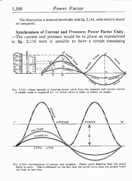
1,506 Pówer Factor
The illustration is lettered identically with fig. 2,114, with which it should be compared.
Synchronism of Current and Pressure; Power Factor Unity. -The current and pressure would be in phase as represented in fig. 2,116 were it possible to have a circuit containing
Ftc. 2,115.-Usual method of drawing power curve from the pressure and current curves. A smaller scale is employed for the power curve in order to reduce its height.
FIG. 2,116-Synchronism of current and pressure. Power curve showing that the power factor is unity. This is indicated by the fact that the power curve does not project below the base or zero line.
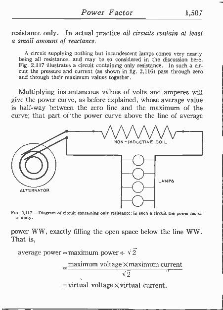
Power Factor 1,501
resistance only. In actual practice all circuits contain at least a small amount of reactance.
A circuit supplying nothing but incandescent lamps comes very nearly being all resistance, and may be so considered in the discussion here. Fig. 2.117 illustrates a circuit containing only resistance. In such a cir- cuit the pressure and current (as shown in fig. 2,116) pass through zero and through their maximum values together.
Multiplying instantaneous values of volts and amperes will give the power curve, as before explained, whose average value is half -way between the zero line and the maximum of the curve; that part of the power curve above the line of average
ALTERNATOR
NON-INDLCTIVE COIL
LAMPS
FIG. 2,117.-Diagram of circuit containing only resistance; in such a circuit the power factor is unity.
power WW, exactly filling the open space below the line WW. That is,
average power = maximum power - J2 maximum voltage X maximum current
J2 = virtual voltage X virtual current.
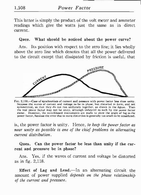
1,508 Power Factor
This latter is simply the product of the volt meter and ammeter readings which give the watts just the same as in direct current.
Ques. What should be noticed about the power curve?
Ans. Its position with respect to the zero line; it lies wholly above the zero line which denotes that all the power delivered
. to the circuit except that dissipated by friction is useful, that
FIG. 2,118.-Case of synchronism of current and pressure with power factor less than unity. Suppose the waves of current and voltage to he in phase, but distorted in form, and not symmetrical, so that they do not rún uniformly together, as shown in the figure. Then the real power factor may not he unity, although indicated as such by the power factor meter. However, the switchboard instruments are made to show the angle of lag as the power factor, because the error due to wave distortion is generally too small to be considered.
is, the power factor is unity. Hence, to keep the power factor as near unity as possible is one of the chief problenzs in alternating current distribution.
Ques. Can the power factor be less than unity if the cur- rent and pressure be in phase?
Ans. Yes, if the waves of current and voltage be distorted as in fig. 2,118.
Effect of Lag and Lead.-In an alternating circuit the amount of power supplied depends on the phase relationship of the current and pressure.
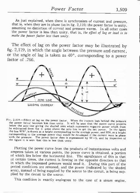
Power Factor 1,509
As just explained, when there is synchronism of current and pressure, that is, when they are in phase (as in fig. 2,116) the power factor is unity, assuming no distortion of current and pressure waves. In all other cases the power factor is less than unity, that is, the effect of lag or lead is to make the power factor less than unity.
The effect of lag on the power factor may be illustrated by fig. 2,119, in which the angle between the pressure and current, or the angle of lag is taken as 40°, corresponding to a power factor of .766.
LAGGING CURRENT
Fic. 2,119.-Effect of lag on the power factor. When the current lags behind the pressure the power factor becomes less than unity. It will be seen that the power curve projects below the zero line giving the shaded area which represents negative power which must le subtracted from the + areas above the zero line to get the net power. In the figure the line WW', is drawn at a height corresponding to the average power, and I IN, at a height corresponding to the average power that would be developed if the current were is phase with the pressure. The power factor then is represented by M =S, and by inspection of the figure it is seen that this is less than unity.
Plotting the power curve from the products of instantaneous volts and amperes taken at various points, the power curve is obtained, a portion of which lies below the horizontal line. The significance of this is that at certain times, the current is flowing in the opposite direction to that in which the impressed pressure would send it. During this part of the period conditions are reversed, and the power (indicated by the shaded area), instead of being supplied by the source to the circuit, is being sup- plied by the circuit to the source.
This condition is exactly analogous to the case of a steam engine,
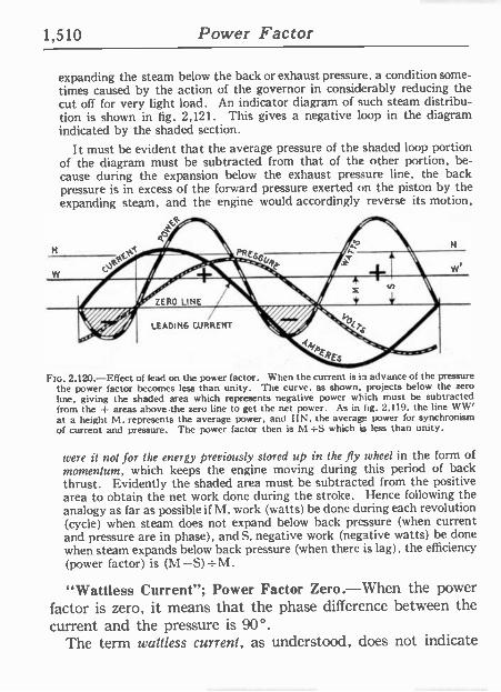
1,510 Power Factor
expanding the steam below the back or exhaust pressure, a condition some- times caused by the action of the governor in considerably reducing the cut off for very light load. An indicator diagram of such steam distribu- tion is shown in fig. 2,121. This gives a negative loop in the diagram indicated by the shaded section.
It must be evident that the average pressure of the shaded loop portion of the diagram must be subtracted from that of the other portion, be- cause during the expansion below the exhaust pressure line, the back pressure is in excess of the forward pressure exerted on the piston by the expanding steam, and the engine would accordingly reverse its motion,
N
w
LEADING CURRENT
ah PRE, 7
Fte. 2,120.-Effect of lead on the power factor. When the current is in advance of the pressure the power factor becomes less than unity. The curve, as shown, projects below the zero line, giving the shaded area which represents negative power which must be subtracted from the -I- areas above the zero line to get the net power. As in fig. 2,119, the line WW' at a height M, represents the average power, and IAN, the average power for synchronism
. of current and pressure. The power factor then is M =S .which L, less than unity.
were it not for the energy previously stored up in the fly wheel in the form of momentum, which keeps the engine moving during this period of back thrust. Evidently the shaded area must he subtracted from the positive area to obtain the net work done during the stroke. Hence following the analogy as far as possible if M, work (watts) be done during each revolution (cycle) when steam does not expand below back pressure (when current and pressure are in phase), and S, negative work (negative watts) be done when steam expands below back pressure (when there is lag), the efficiency (power factor) is (M
"Wattless Current"; Power Factor Zero.-When the power factor is zero, it means that the phase difference between the current and the pressure is 90°.
The term witness current, as understood, does not indicate
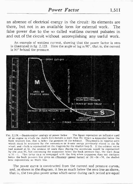
Power Factor 1,511
'
an absence of electrical energy in the circuit: its elements are there, but not in an available form for external work. The false power due to the so called wattless current pulsates in and out of the circuit without accomplishing any useful work.
An example of wattless current, showing that the power factor is zero is illustrated in fig. 2,123. Here the angle of lag is 90°, that is, the current is 90° behind the pressure.
r."--. _1
45 --1
40,__
óI
:0=
f5=
20 _
ál EXHAUST OR BACK PRESSURE LINE
SHORT CUT-OFF
u :
1EAME%PAKDiHE ¡BELOW BACK PRESSURE
14
PERICDOF BACK 'MUST-!
' . . 1/4 REA (L00P) 0- NE6ATIVE WORK .
-2- - - ROHE -- I
N'tc. 2,125.-Steam engine analogy of power factor. The figure represents an indicator card of an engine in which the steam distribution is such that the steam is expanded below the back pressure line, that is below the pressure of the exhaust. This, results in negatrre work which must be overcome by the momentum or k,nelu energy previously stored in the fly wheel, and which is represented on the diagram by the shaded loop S. if the exhaust valve had opened at G, the amount of work done during the revolution would he represented by the area M, but continuing the expansion below the back pressure line, the work done is M -S. This latter case as compared with the first when expansion does not continue below the back pressure line gives art efficiency (power factor) of (M -Si =M, the shaded area representing so much loss.
The power curve is constructed from the current and pressure curves, and, as shown in the diagram, it lies as much below the zero line as above, that is, the two plus power areas which occur during each period are equal
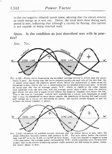
1.512 Power Factor
to the two negative (shaded) power areas, showing that the circuit returns as much energy as is sent out. Hence, the total work done during each period is zero, indicating that although a current be flowing, this current is not capable of doing external work.
Ques. Is the condition as just described met with in prac- tice?
Ans. No.
W ZERO LINE ////////////// ZERO LINE
FIG. 2,122.-Power curve illustrating the so-called wattless current in which case the power lactor is zero. By noting that the curve projects equally on each side of the zero line, the -I- power areas equal the negative power areas, hence the summation of these areas for the period is zero. that is, the two + areas minus the two shaded areas equal zero. It should be noted that the line of average power Vt W', which is visible in the other figures here coincides with the zero line, and the average power then is zero, since the positive part above the zero line is equal to and offsets the negative 'shaded) part below the line. This is the case o1 "wattless" current and (considering a circuit with resistance so small that it may he considered as zero) shows plainly the possibility of having full load current and voltage on a circuit yet delivering no power. the current simply surging to and fro without an actual transfer tf power.
FIG. 2,123.-Example of wattless current showing that the power factor is zero when the phase difference between current and pressure is 90°. For zero power factor the current may lead 90° as in fig. 2,122, or lag 90° as here shown Since the shaded or negative areas =the plus areas, the average power (indicated by WW'. which coincides with the zero line) is zero, that is the circuit is carrying current under pressure yet delivering no power, hence, the power factor is zero.
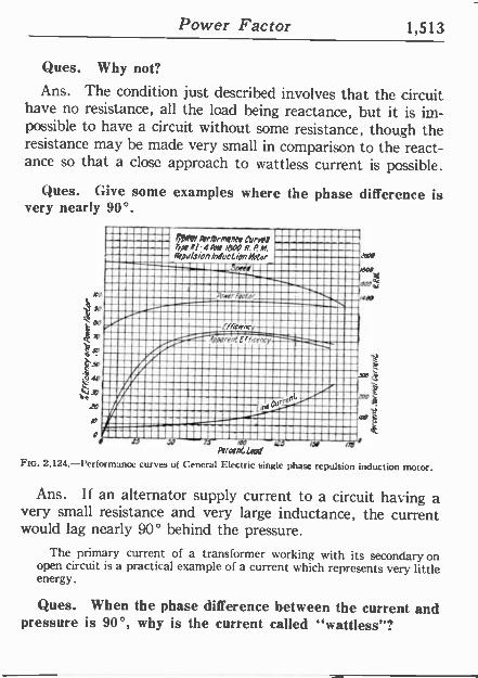
Power Factor 1,513
Ques. Why not?
Ans. The condition just described involves that the circuit have no resistance, all the load being reactance, but it is im- possible to have a circuit without some resistance, though the resistance may be made very small in comparison to the react- ance so that a close approach to wattless current is possible.
Ques. Give some examples where the phase difference is very nearly 90°.
-l-
>7' r
0001 Ar/DnMl7N CLrrrl 4Pok/B00R.PM
Nip/Sio/7 Induction Odor
er peor
MIME: fhrKnrr :i¡
pqerrrkClfre
1
n<a re
zl IAD
Ív sepC Lad FIG. 2,124.-Performance curves of General Electric single phase repulsion induction motor.
Ans. If an alternator supply current to a circuit having a very small resistance and very large inductance, the current would lag nearly 90° behind the pressure.
The primary current of a transformer working with its secondary on open circuit is a practical example of a current which represents very little energy.
Ques. When the phase difference between the current and pressure is 90°, why is the current called "wattless"?
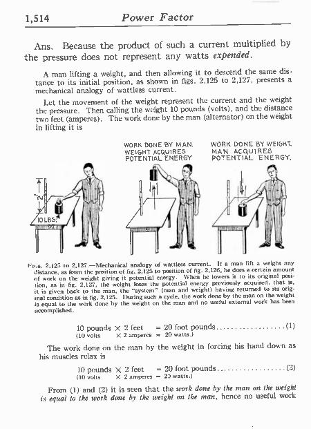
1,514 Power Factor
Ans. Because the product of such a current multiplied by
the pressure does not represent any watts expended.
A man lifting a weight, and then allowing it to descend the same dis-
tance to its initial position, as shown in figs. 2,125 to 2,127, presents a
mechanical analogy of wattless current.
Let the movement of the weight represent the current and the weight
the pressure. "Then calling the weight 10 pounds (volts), and the distance two feet (amperes). The work done by the man (alternator) on the weight
in lifting it is
WORK DONE BY MAN. WEIGHT ACQUIRES POTENTIAL ENERGY
WORK DONE BY WEIGHT. MAN ACQUIRES POTENTIAL ENERGY.
Fins. 2,125 to 2,127.-Mechanical analogy of wattless current, a man lift a weight any
distance, as from the position of fig. 2,125 to position of fig. 2,126 he does a certain amount of work on the weight giving it potential energy. When he lowers it to its original posi-
tion, as in fig. 2,127. the weight loses the potential energy previously acquired, that is,
it is given hack to the man, the "system" (man and weight) having returned to its orig-
inal condition as in fig. 2,125. During such a cycle, the work done by the man on the weight is equal to the work done by the weight on the man and no useful external work has been
accomplished.
10 pounds X 2 feet = 20 foot pounds.. (1) (10 volts X 2 amperes = 20 watts.)
The work done on the man by the weight in forcing his hand down as
his muscles relax is
10 pounds X 2 feet = 20 foot pounds. - (2) (10 volts X 2 amperes = 23 watts.)
' From (1) and (2) it is seen that the work done by the man on the weight
is equal to the work done by the weight o)f the man, hence no useful work
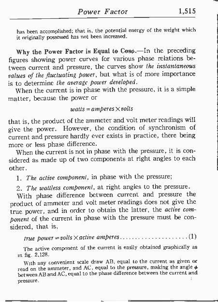
Power Factor 1,515
has been accomplished; that is, the potential energy of the weight which
it originally possessed has not been increased.
Why the Power Factor is Equal to Coso.-In the preceding figures showing power curves for various phase relations be-
tween current and pressure, the curves show the instantaneous values of the fluctuating power, but what is of more importance is to determine the average power developed.
When the current is in phase with the pressure, it is a simple matter, because the power or
watts =amperes X volts
that is, the product of the ammeter and volt meter readings will
give the power. However, the condition of synchronism of current and pressure hardly ever exists in practice, there being more or less phase difference.
When the current is not in phase with the pressure, it is con-
sidered as made up of two components at right angles to each
other. 1. The active component, in phase with the pressure;
2. The wattless component, at right angles to the pressure. With phase difference between current and pressure the
product of ammeter and volt meter readings does not give the true power, and in order to obtain the latter, the active com-
ponent of the current in phase with the pressure must be con-
sidered, that is,
true power = volts X active amperes (1)
The active component of the current is easily obtained graphically as
in fig. 2,128.
With any convenient scale draw AB, equal to the current as given or
read on the ammeter, and AC, equal to the pressure, making the angle
between AB and AC, equal to the phase difference between the current and
pressure.
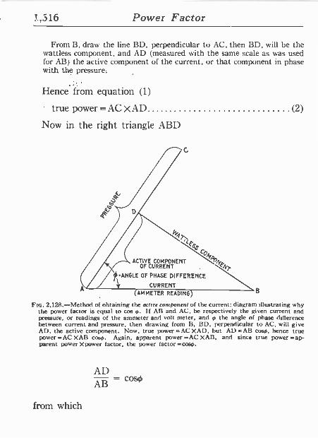
1,516 Power Factor
' From B, draw the- line I3D, perpendicular to AC, then BI), will be the wattless component, and \I) (measured with the same scale as was used for AB) the active component of the current, or that component in phase
. with the pressure:
-
Hence from equation (1)
true power =AC XAD (2)
.Now in the right triangle ABD
A
\FS o
ACTIVE COMPONENT OF CURRENT
ANCLE OF PHASE DIFFERENCE
CURRENT
FN
(AMMETER READING B
FIG. 2,128.-Method of obtaining the acure component of the current; diagram illustrating why the power factor is equal to cos o. If AB and AC, be respectively the given current and pressure, or readings of the ammeter and volt meter, and 0 the angle of phase difference between current and pressure, then drawing from B, HI), perpendicular to AC, will give Al), the active component. Now, true power =AC XAD, hut. AD =AI3 coso, hence true power =AC XAB corn. Again, apparent power =AC XAI3, and since true power =ap- parent power Xpower factor, the power factor =coso.
AD AB = coso
from which
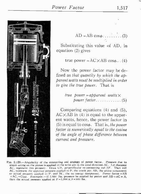
Power Factor 1,517
Ij
AD =AB cow) (3)
Substituting this value of AD, in equation (2) gives
true power =AC XAB coso... (4)
Now the power factor may be de- fined as that quantity by which the ap- parent watts must be multiplied in order to give the true power. That is
true power =apparent walls X power factor (5)
íq
1811
Comparing equations (4) and (5), AC 1B in (4) is equal to the appar- ent watts, hence, the power factor in (5) is equal to cow). That is, the power factor is numerically equal to the cosine of the angle of phase difference between current and pressure.
FIG. 2.129.-Angularity of the connecting rod analogy of power factor. Pressure due to steam acting on the piston is applied to the wrist pin in the axial direction AC. Let distance AC. represent this pressure. Draw CB. perpendicular to connecting rod AP. Then wit: AC. represent the apparent pressure applied to P. the crank pin: AB, the active component or actual pressure applied to 1', and BC. the no energy component. Power factor=AB SAC, =Cosm. Example.-If I,txx) lbs. pressure be applied by piston and AB=AC=.9,
then the actual pressure applied at P -I,000 X.9 =90t) lbs.
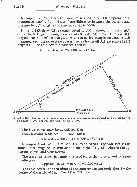
1,518 Power Factor
Example 1.-An alternator supplies a current of 200 amperes at a pressure of 1,000 volts. If the phase difference between the current and pressure be 30°, what is the true power developed?
In fig. 2,130, draw AB, to scale, equal to 200 amperes, and draw AC, of indefinite length making an angle of 30° with AB. From B, draw BD, perpendicular to AC, which gives AD, the active component, and which measured with the same scale as was used in laying off AB, measures 173.2 amperes. The true power developed then is
true watts=173.2X1,000=173.2 kw.
9F,S
\1S
200 AMPERES CURRENT
Fio. 2,130.-Diagram for obtaining the active component of the current in a circuit having a current of 200 amperes and angle of lag of 30°.
The true power may he calculated thus: From a cosine table cos 30° = .866, hence
true watts = 200 x1,000 X .866 =173.2 kw.
Example 2.-If in an alternating current circuit, the volt meter and ammeter readings be 110 and 20 and the angle of lag 45°, what is thé ap- parent power and true power?
The apparent power is simply the product of the current and pressure readings or
apparent power=20X110=2,200 watts The true power is the product of the apparent power multiplied by the
cosine of the angle of lag. Cos 45° = .707, hence
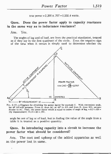
Power Factor 1,519
true power =2,200 X .707 =1,555.4 watts.
Ques. Does the power factor apply to capacity reactance in the same way as to inductance reactance?
Ans. Yes.
The angles of lag and of lead, are from the practical standpoint, treated as if they lay in the first quadrant of the circle. Even the negative sign of the tano when it occurs is simply used to determine whether the
C
C
-14
OAO \r POWER FACTOR
cos CAE p :0.707
AMPERES E -- BY MEASUREMENT 10
B
Ftc. 2,131.-Diagram for obtaining the power factor for example 2. With convenient scale. lay of! AB =20 amperes. From A, draw AC. at 45° to AB. and from B, draw BD, perpen- dicular to AC. Then, the power (actor which is equal to cosine of angle of lag, =AD .-AB = (by measurement) 14.15 =20 =.707.
angle he one of lag or of lead, but in finding the value of the angle from a table it is treated as a positive quantity.
Ques. In introducing capacity into a circuit to increase the power factor what should be considered?
Ans. The cost and upkeep of the added apparatus as well as the power lost in same.
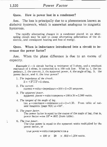
1,520 Power Factor
Ques. flow is power lost in a condenser?
Ans. The loss is principally due to a phenomenon known as dielectric hysteresis, which is somewhat analogous to magnetic hysteresis.
The rapidly alternating charges in a condenser placed in an alter- nating circuit may he said to cause alternating polarization of the di- electric, and consequent heating and loss of energ} .
Ques. When is inductance introduced into a circuit to in- crease the power factor?
Ans. When the phase difference is due to an excess of capacity.
Example 1.-A circuit having a resistance of 3 ohms, and a resultant reactance of 4 ohms, is connected to a 100 volt line. What is: 1, the im- pedance, 2. the current, 3, the apparent power, 4, the angle of lag, 5, the power factor, and 6, the true power?
1. The impedance of the circuit. Z= I32+4' =5 ohms.
2. The current. current = volts _impedance =100 = 5 = 20 amperes.
3. The apparent power. apparent power = volts X amperes =100 X 20 =2,000 watts.
4. The tangent of the angle of lag. tan 4. =reactance -resistance =4 -3 =1.33. From table of nat- ural tangents (page 921) =53°.
5. The power factor. The power factor is equal to the cosine of the angle of lag, that is, power factor = cos 53° = .602 (from table) .
6. The true power. The true power is equal to the apparent watts multiplied by the power !actor, or
true power = volts X amperes X cos
= 100 X 20 X .602 =1,204 watts.
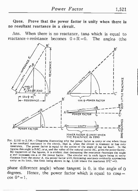
Power Factor 1,521
Ques. Prove that the power factor is unity when there is no resultant reactance in a circuit.
Ans. When there is no reactance, tang, which is equal to reactance _resistance becomes 0 +R =0. The angled (the
B' ,
I
I
I / I / / á I á // I
I
RLEADJ_
1 RESISTANCE C
I
.t
POWER FACTOR
POWER FACTOR
J C'
Cos 'POWER FACTOR
B,> _ W t)NIT-- C C'
POWER FACTOR 15 UNITY WHEN
J B'á
o x THE REACTANCE 15 ZERO
FIG. 2,132 to 2,136.-Diagrams illustrating why the power factor is unity or one when there is no resultant reactance in the circuit, that is, when the circuit is resonant or has only resistance. The power factor is equal to the cosine of the angle of lag (or lead). In the figures this angle is BAC, or 0, and the value of the natural cosine AC. gives the power factor. By inspection of the figures, it. is evident that decreasing the reactance decreases the angle 0 and increases cos e, or the power factor. The circular arc in each figure being at unity distance from the center A. the power factor with decreasing reactance evidently approaches unity as its limit, this limit being shown in fig. 2,136 where the reactance WC' =0.
phase difference angle) whose tangent is 0, is the angle of O degrees. Hence, the power factor which is equal to caso = cos 00=1.
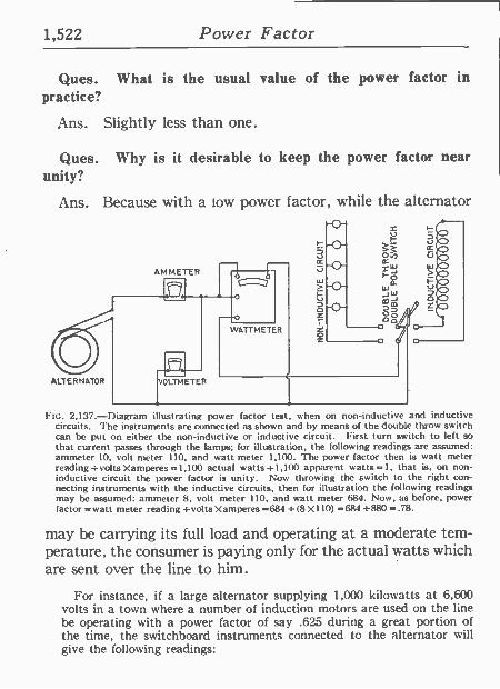
1,522 Power Factor
Ques. What is the usual value of the power factor in practice?
Ans. Slightly less than one.
Ques. Why is it desirable to keep the power factor near unity?
Ans. Because with a low power factor, while the alternator
AMMETER
ALTERNATOR
Ftc. 2,137.-Diagram illustrating power factor test, when on non -inductive and inductive circuits. The instruments arc connected as shown and by means of the double throw switch can he put on either the non -inductive or inductive circuit. First turn switch to left so that current passes through the lamps; for illustration, the following readings are assumed: ammeter 10, volt meter 110, and watt meter 1,100. The power factor then is watt meter reading =volts Xamperes =1,100 actual watts =1,100 apparent watts =1, that is, on non - inductive circuit the power factor is unity. Now throwing the switch to the right con- necting instruments with the inductive circuits, then for illustration the following readings may be assumed: ammeter 8, volt meter 110, and watt meter 684. Now, as before, power factor =watt meter reading =volts Xamperes =684 _ (8 X110) =684 4-880 =.78.
may be carrying its full load and operating at a moderate tem- perature, the consumer is paying only for the actual watts which are sent over the line to him.
For instance, if a large alternator supplying 1,000 kilowatts at 6,600 volts in a town where a number of induction motors are used on the line be operating with a power factor of say .625 during a great portion of the time, the switchboard instruments connected to the alternator will give the following readings:
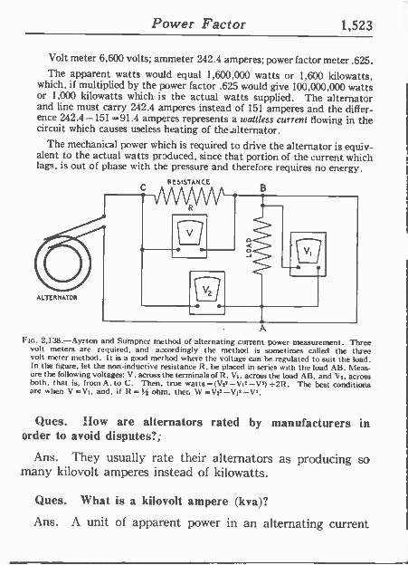
Power Factor 1,523
Volt meter 6,600 volts; ammeter 242.4 amperes; power factor meter .625. The apparent watts would equal 1,600,000 watts or 1,600 kilowatts,
which, if multiplied by the power factor .625 would give 100,000,000 watts or 1,000 kilowatts which is the actual watts supplied. The alternator and line must carry 242.4 amperes instead of 151 amperes and the differ- ence 242.4-151 =91.4 amperes represents a watttess current flowing in the circuit which causes useless heating of the alternator.
The mechanical power which is required to drive the alternator is equiv- alent to the actual watts produced, since that portion of the current which lags, is out of phase with the pressure and therefore requires no energy.
A
Fm. 2,138.-Ayrton and Sumpner method of alternating curren power measurement. Three volt meters are required, and a.cordingly the method is sometimes called the three volt meter method. It is a good method where the voltage can be regulated to suit the load. In the figure, let the non -inductive resistance R. he placed in series with the load AB. Meas- ure the following voltages: V, across the terminals of R. Vt, across the load AB, and V,. across both, that is, from A, to C. Then, true watts = (V;* -Vt' -V') =2R. The best conditions are when V=Vt, and, if R ohm, ther. \V=V:'-Vt'-V2.
Ques. How are alternators rated by manufacturers in order to avoid disputes?;
Ans. They usually rate their alternators as producing so many kilovolt amperes instead of kilowatts.
Ques. What is a kilovolt ampere (kva)?
Ans. A unit of apparent power in an alternating current
1,524 Power Factor
circuit which is equal to one kilowatt when the power factor is equal to. one.
The machine mentioned on page 1,522 would he designed to carry 151
amperes without overheating and also carry slight overloads for short periods. It would he rated as 6.6 kilovolts and 151 amperes which would equal approximately 1,000 kilowatts when the power factor is 1 or unity, and it should operate without undue heating. Now the lower the power factor becomes, the greater the heating trouble will be in trying to produce the 1,000 actual kilowatts.
Ques. How can the power factor be kept high?
Ans. By carefully designing the motors and other apparatus and even making changes in the field current of motors which are already installed.
Ques. Ilow is the power factor determined in station op- eration?
Ans. Not by calculation, but by reading a meter which forms one of the switchboard instruments.
Ques. When is the power factor meter of importance in station operation, and why?
Ans. When rotary converters are used on a.c. lines for sup- plying direct currents and the sub -station operators are kept busy adjusting the field rheostat of the rotary to maintain a high power factor and prevent overheating of the alternators during the time of day when there is the maximum demand for current or the peak of the load.
Example.-An alternator delivers current at 800 volts pressure at a frequency of 60, to a circuit of which the resistance is 75 ohms and .25 henry.
Determine: a, the value of the current; b, angle of lag; c, apparent watts; d, power factor; e. true power.
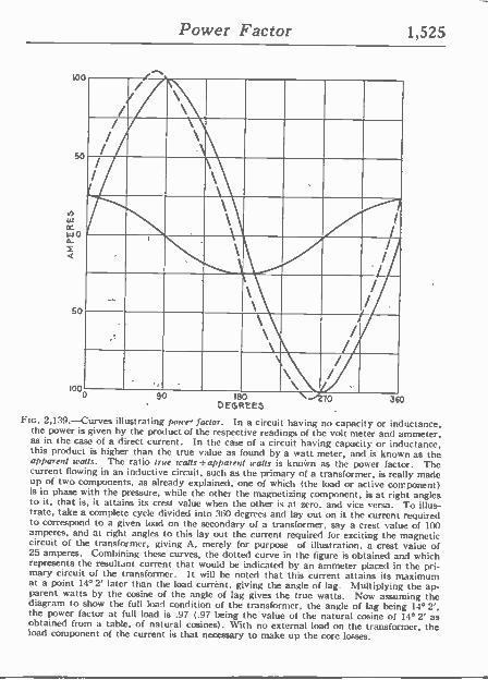
Power Factor 1,525
loo
50
wo
50
10o
// / `\ /
I I
\\ \ /
I \ 1
\ \
1
,
\ / /
I \ \
1
I
\\ I
/ \ \ \ / /
90 180 X1270 DEGREES
360
Ftc. 2,139.-Curves illustrating pourer factor. In a circuit having no capacity or inductance. the power is given by the product of the respective readings of the volt meter and ammeter, as in the case of a direct current. In the case of a circuit having capacity or inductance. this product is higher than the true value as found by a watt metér, and is known as the apparent watts. The ratio true watts _apparent watts is known as the power factor. The current flowing in an inductive circuit, such as the primary of a transformer, is really made up of two components, as already explained, one of which (the load or active component) is in phase with the pressure, while the other the magnetizing component, is at right angles to it, that is, it attains its crest value when the other is at zero, and vice versa. To illus- trate, take a complete cycle divided into 360 degrees and lay out on it the current required to correspond to a given load on the secondary of a transformer, say a crest value of 100 amperes, and at right angles to this lay out the current required for exciting the magnetic circuit of the transformer, giving A, merely for purpose of illustration, a crest value of 25 amperes. Combining these curves, the dotted curve in the figure is obtained and which represents the resultant current that would be indicated by an ammeter placed in the pri- mary circuit of the transformer. It will be noted that this current attains its maximum at a point 14° 2' later than the load currént, giving the angle of lag. Multiplying the ap- parent watts by the cosine of the angle of lag gives the true watts. Now assuming the diagram to show the full load condition of the transformer, the angle of lag being 14°2', the power factor at full load is .97 (.97 being the value of the natural cosine of 14° 2' as obtained from a table, of natural cosines). 1Vith no external load on the transformer, the load component of the current is that necessary to make up the core losses.
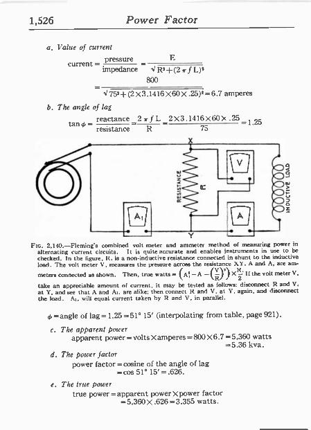
1,526 Power Factor
a. Value of current
current = pressure E
impedance V R2+(2,r fL)2 800
4752+-(2 X3.1416 X60 X .25)2=6.7 amperes
b. The angle of lag
tangy_ reactance 2 rf L2X3.1416X60X.25-1.25 resistance R 75
Y
FIG. 2,140.-Fleming's combined volt meter and ammeter method of measuring power in alternating current circuits. It is quite accurate and enables instruments in use to be
checked. In the figure, R. is a non -inductive resistance connected in shunt to the inductive load. The volt meter V, measures the pressure across the resistance X. . A and A, are am-
meters connected as shown. Then, true watts = (A -A -(V>r Xt.' If the volt meter V. R 2
take an appreciable amount of current, it may be tested as follows: disconnect R and V, at Y, and see that A and Ai. are alike; then connect R and V, at Y, again, and disconnect the load. At, will equal current taken by It and V, in parallel.
=angle of lag=1.25 =51° 15' (interpolating from table, page 921).
c. The apparent power apparent power = volts X amperes = 800 X 6.7 =5,360 watts
=5.36 kva. d. The power factor
power factor =cosine of the angle of lag =cos 51° 15'=.626.
e. The true power true power =apparent power Xpower factor
=5,360 X .626 =3.355 watts.
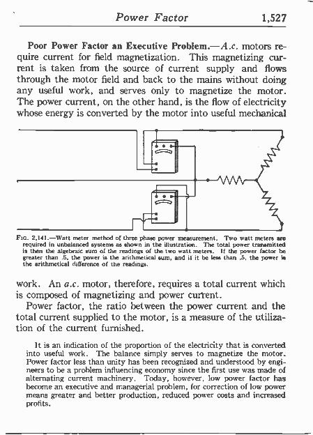
Power Factor 1,527
Poor Power Factor an Executive Problem.-A.c. motors re- quire current for field magnetization. This magnetizing cur- rent is taken from the source of current supply and flows through the motor field and back to the mains without doing any useful work, and serves only to magnetize the motor. The power current, on the other hand, is the flow of electricity whose energy is converted by the motor into useful mechanical
FIG. 2,141.-Watt meter method of three phase power measurement. Two watt meters are required in unbalanced systems as shown in the illustration. The total power transmitted is then the algebraic sum of the readings of the two watt meters. If the power factor be greater than .5, the power is the arithmetical sum, and it it be less than .5, the power is the arithmetical difference of the readings.
work. An a.c. motor, therefore, requires a total current which is composed of magnetizing and power current.
Power factor, the ratio between the power current and the total current supplied to the motor, is a measure of the utiliza- tion of the current furnished.
It is an indication of the proportion of the electricity that is converted into useful work. The balance simply serves to magnetize the motor. Power factor less than unity has been recognized and understood by engi- neers to be a problem influencing economy since the first use was made of alternating current machinery. Today, however, low power factor has become an executive and managerial problem, for correction of low power means greater and better production, reduced power costs and increased profits.
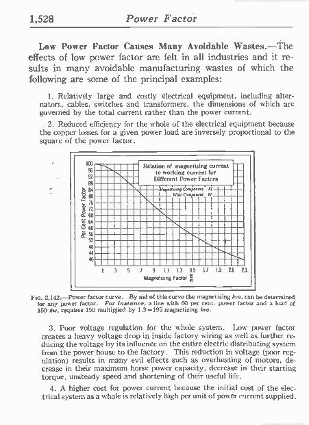
1,528 Power Factor
Low Power Factor Causes Many Avoidable Wastes.-The effects of low power factor are felt in all industries and it re- sults in many avoidable manufacturing wastes of which the following are some of the principal examples:
1. Relatively large and costly electrical equipment, including alter- nators, cables, switches and transformers, the dimensions of which are governed by the total current rather than the power current.
. 2. Reduced efficiency for the whole of the electrical equipment because the copper losses for a given power load are inversely proportional to the square of the power factor.
100
96
92
88
ó 84
Á 80 r 76
3 72
ti 68
cl64
60
g` 56
52
48
44
40
Relation of magnetizing current to working current for
Different Toner Factors
,Napnd, ,np Con point t
Walt Comronrnt W
I 3 5 / 9 11 13 15 II 19 21 23
Magnetizmg Facto
Ftc. 2,142.-Power factor curve. By aid of this curve the magnetizing kva. can be determined for any power factor. For instance. a line with 6O per cent. power factor and a load of 150 kw. requires 150 multiplied by 1.3 =195 magnetizing kva.
3. Poor voltage regulation for the whole system. Low power factor creates a heavy voltage drop in inside factory wiring as well as further re- ducing the voltage by its influence on the entire electric distributing system from the power house to the factory. This reduction in voltage (poor reg- ulation) results in many evil effects such as overheating of motors, de- crease in their maximum horse power capacity, decrease in their starting torque, unsteady speed and shortening of their useful life.
4. A higher cost for power current because the initial cost of the elec- trical system as a whole is relatively high per unit of power r'lrrent supplied.
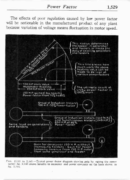
Power Factor 1,529
The effects of poor regulation caused by low power factor will be noticeable in the manufactured product of any plant because variation of voltage means fluctuation in motor speed.
700 H.P. Work Value L
Wattmeter Reading 850 H.P. Work Value
150 M.P. gained by raising Power -factor from 7o%tci85%
This .radius determines the copper ,n generator and feeders or limits the duty of exis:inq generators and feeders
ThisI-ihe shows how much work the above heating value can 'be made to de'iver at various power -factors
The- ultirr a result at unity power -factor is 100% work
Group of Induction Motors 700 H.P.-70%Power-factor }
Group of lnduction,Motors (610'H.P)\ and 5 nchron .'\ 850 M.P.at 85°/, Same load on generators Power -factor
and.feeders a
Gain for consumer 150 H.P. without increasing feeders - Gain for Roweril Company revenue from 150 M. P. motor( from same generator and feeder J
FIGS. 2,143 to 2,145.-Typical power factor diagram showing gain by raising the power factor; fig. 2,145 shows benefits to consumer and power company on Use basis shown in fig. 2,144.
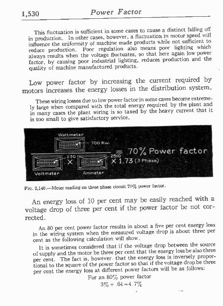
1,530 Power Factor
This fluctuation is sufficient in some cases to cause a distinct falling off
in production. In other cases, however, a fluctuation in motor speed will
influence the uniformity of machine made products while not sufficient to
reduce production. Poor regulation also means poor lighting which
always results when the voltage fluctuates, so that here again low power
factor, by causing poor industrial lighting, reduces production and the
quality of machine manufactured products.
Low power factor by increasing the current required by
motors increases the energy losses in the distribution system.
These wiring losses due to low power factor in some cases become extreme-
ly large when compared with the total energy required by the plant and
in many cases the plant wiring is so taxed by the heavy current that it
is too small to give satisfactory service.
'Wattmeter '
t . ' ' ,....,1- - , ; ..700 Kw.. , , . o r ~ '70% Powerfactor 23C 251Ó'
)`,-;-,1 X. X' 1.73 (3 Pháse) . '
Vóltmetier /ammeter
Ftc. 2,146.-Meter reading on three phase circuit 70% power factor.
An energy loss of 10 per cent may be easily reached with a
voltage drop of three per cent if the power factor be not cor-
rected. An 80 per cent power factor results in about a five per cent energy loss
in the wiring system when the measured voltage drop is about three per
cent as the following calculation will show.
It is sometimes considered that if the voltage drop between the source
of supply and the motor be three per cent that the energy loss be also three
per cent. The fact is, however. that the energy loss is inversely propor-
tional to the square of the power factor so that if the voltage drop be three
per cent the energy loss at different power factors will be as follows:
For an 80% power factor 3%_.64=4.7%
Power Factor 1,531
For a 55% power factor 3%±.3=10%
Low Power Factor Increases Operating Cost.-Manufactur- ers who operate their own generating plants suffer a large in- vestment loss through low power factor. Excess capacity of alternators, lines, transformers, feeders, and switching equip- ment is necessary to take care of magnetizing current.
Electrical investment cost varies inversely (approximately) as the power factor so that a system designed for 70 per cent power factor costs about 40 per cent more than one designed for unity power factor.
In the case of a manufacturer who purchases current his power rate must contain all of the generating cost as well as a profit on these costs so that if the power factor of the generating system be low, the manufacturer in his power rate pays the interest charges upon the extra investment caused by low power factor.
TEST QUESTIONS
1. Define the term power factor. 2. Give two marine analogies illustrating power factor. 3. What is the difference between the true power and the
apparent power? 4. What is usually meant by power factor? 5. Upon what does the power factor depend?
6. How does the power factor vary in value?
7. What is the effect of lag or lead of the current on the power factor?
8. Give method of obtaining the power curve.
9. Under what condition is the power factor unity?
1,532 Power Factor
10. What should be noticed about the power curve? 11. Can the power factor be less than unity if the current
and pressure he in phase? 12. What is the effect of lag and lead on power factor? 13. Can the power factor be zero? 14. What does the term wattless current mean? 15. Give steam engine analogy of power factor. 16. Give some examples where the phase difference is
very nearly 90°. 17. Why is the power factor equal to cos¢? 18. Does the power factor apply to capacity reactance in
the same way as to inductance reactance? 19. How is power lost in a condenser? 20. When is inductance introduced into a circuit to
increase the power factor? 21. Prove that the power factor is unity when there is no
resultant reactance in a circuit. 22. What is the usual value of the power factor in prac-
tice? 23. Why is it desirable to keep the power factor near
unity? 24. How are alternators rated by manufacturers in order
to avoid disputes? 25. What is a kilovolt ampere (kva)? 26. flow can the power factor be kept high? 27. How is the power factor determined in station opera-
tion?
Alternators 1,533
CHAPTER 50
Alternators Use of Alternators.*-The great increase in the application
of electricity for supplying power and for lighting purposes in industry, commerce, and in the home, is due chiefly to the economy of distribution of alternating current.
Direct current may he used to advantage in densely populated districts, but where the load is scattered, it requires, on account of its low voltage, too great an investment in distributing lines. In such cases the alternator is used to advantage, for while commutators can be built for cdlecting direct current up to 1,000 volts, alternators can be built up to 12,000 volts or more, and this voltage increased, by step up transformers of high economy, up to 100,000 volts or more. Since the copper cost is inversely as the square of the voltage, the great advantage of alternating current systems is clearly apparent.
The use of alternating current thus permits a large amount of energy to be economically distributed over a wide area from a single station, not only reducing the cost of the wiring, but securing greater economy by the use of one large station, instead of several small stations.
The higher voltages generated by alternators enables the transmission of electrical energy to vastly greater distances than possible by a direct current system, so that the energy from many waterfalls that otherwise would go to waste may be utilized.
Classes of Alternator.-There are various ways of classifying alternators. They may be divided into groups, according to
*NOTE.-The author objects to the ridiculous terms alternating current generator for alter- nator and direct current generator for dynamo. Why use three words in place of one?
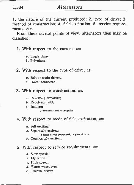
1,534 Alternators
1, the nature of the current produced; 2, type of drive; 3, method of construction; 4, field excitation; 5, service require- ments, etc.
From these several points of view, alternators then may be classified:
1. With respect to the current, as:
a. Single phase; b. Polyphase.
2. With respect to the type of drive, as:
a. Belt or chain driven; b. Direct connected.
3. With respect to construction, as:
a. Revolving armature; b. Revolving field; c. Inductor.
Homopolar and heteropolar.
4. With respect to mode of field excitation, as:
a. Self -exciting; b. Separately excited;
Exciter direct connected, or bear drivan.
e. Compositely excited.
5. With respect to service requirements, as:
a. Slow speed; b. Fly wheel; e. High speed; d. \\ ater wheel type; e. Turbine driven.
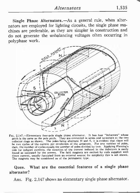
Alternators 1,535
Single Phase Alternators.-As a general rule, when alter- nators are employed for lighting circuits, the single phase ma-
chines are preferable, as they are simpler in construction and do not generate the unbalancing voltages often occurring in polyphase work.
Fi T' (.11
I
E.5 i Ny
1<"
I
J ---'
FIG. 2,147.-Elementary four -pole single phase alternator. It has four "inductors' whose pitch is the same as the pole pitch. They are connected in series and terminate at the two collector rings as shown. The poles being alternate N and S. it is evident that there will be two cycles of the current per revolution of the armature. For any number of poles.
then, the number of cycles equals the number of poles divided by two. Applying Fleming's rule for induced currents, the direction of the current induced in the inductors is easily found as indicated by the arrows. The field magnets are excited by coils supplied with direct current, usually furnished front an external source; for simplicity this is not shown. The magnets may be considered as of the permanent type.
Ques. What are the essential features of a single phase alternator?
Ans. Fig. 2,147 shows an elementary single phase alternator.
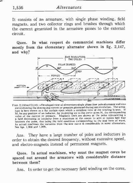
1,536 Alternators
IB0° 360°
R
PERIOD --7
It consists of an armature, with single phase winding, field magnets, and two collector rings and brushes through which the current generated in the armature passes to the external circuit.
Ques. In what respect do commercial machines differ mostly from the elementary alternator shown in fig. 2,147, and why?
LONE REVOLUTIONI l TWO CYCLES I I
POLAR DEGREES
180°
FIGS. 2,148 and 2,149.-Developed view of elementary single phase four pole alternator and sine
curve showing the alternating current of pressure generated during one revolutioh. The arma-
ture is here shown as a flat surface upon which a complete view of the winding is seen. If M, be any position of an inductor, by projecting up to the curve gives N, the corresponding value of the current or pressure. Magnetic lines are shown at the poles representing a
a field decreasing in intensity from a maximum at the center to zero at points half way
between the poles, this being the field condition corresponding to the sine form of wave.
In actual machines the variation from the sine curve is considerable in some alternators. See figs. 1,968 and 1,969.
Ans. They have a large number of poles and inductors in
order to obtain the desired frequency, without excessive speed, and electro -magnets instead of permanent magnets.
Ques. In actual machines, why must the magnet cores be spaced out around the armature with considerable distance between them?
Ans. In order to get the necessary field winding on the cores,
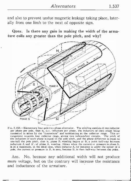
Alternators 1,537
and also to prevent undue magnetic leakage taking place, later- ally from one limb to the next of opposite sign.
Ques. Is there any gain in making the width of the arma- ture coils any greater than the pole pitch, and why?
-------y FIG. 2,150.-Elementary four pole two phase alternator. The winding consists of one inductor
per phase per pole, that is, iov, inductors per phase, the inductors of each phase being connected in series by the "connectors" and terminating at the collector rings. This ar- rangement requires four collector rings, giving two independent circuits. The Fitch of the inductors of each phase is equal to the pole pitch, and the phase difference is equal to one-half the pole pitch, that is, phase B, winding begins at B, a point half -way 'between inductors A and A', of phase A, winding. Hence when the current or pressure in phase A, is at a maximum, in the ideal case, when inductor A, for instance is under the center of a pole, the current or pressure in B, is zero, because B, is then half -way between the poles.
Ans. No, because any additional width will not produce more voltage, but on the contrary will increase the resistance and inductance of the armature.
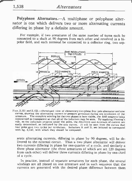
1,538 Alternators
Polyphase Alternators.-A multiphase or polyphase alter- nator is one which delivers two or more alternating currents differing in phase by a definite amount.
For example, if two armatures of the same number of turns each be connected to a shaft at 90 degrees from each other and revolved in a bi- polar field, and each terminal be connected to a collector ring, two sep-
ONE REVOLUTION¿¿ TWO CYCLES f 1
Fics.2,151 and 2,152.-Developed view of elementary two phase four pole alternator and sine curves, showing the alternating current or pressure generated during one revolution of the armature. The complete winding for the two phases is here visible, the field magnets being represented as transparent so that all of the inductors may be seen. By applying Fleming's rule, as the inductors progress under the poles, the directions and reversals of current arc easily determined, as indicated by the sine curves. It will he seen from the curves that four poles give two cycles per revolution. Inductors A and B, are lettered to correspond with lig. 2,150, with which they should be compared.
arate alternating currents, differing in phase by 90 degrees, will be de- livered to the external circuit. Thus a two phase alternator will deliver two currents differing in phase by one -quarter of a cycle, and similarly a three phase alternator (the three armatures of which are set 120 degrees from each other) will deliver three currents differing in phase by one-third of a cycle.
In practice, instead of separate armatures for each phase, the several windings are all placed on one armature and in such sequence that the currents are generated with the desired phase difference between them
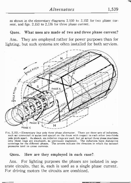
Alternators 1,539
as shown in the elementary diagrams 2,150 to 2,152 for two phase cur- rent, and figs. 2,153 to 2,155 for three phase current.
(hues. What uses are made of two and three phase current?
Ans. They are employed rather for power purposes than for lighting, but such systems are often installed for both services.
/ I
/----/ r -r--- /
PHASE C
_ 1
N
Fro. 2,153.-Elementary four pole three phase alternator. There are three sets of inductors, each set connected in series and spaced on the drum with respect to each other two-thirds pole pitch apart. As shown, six collector rings are used, hut on actual three phase machines only three rings are employed, as previously explained. The inductors have distinctive coverings for the different phases. The arrows indicate the direction in which the induced pressules tend to cause currents.
(hues. How are they employed in each case?.
Ans. For lighting purposes the phases are isolated in sep- arate circuits, that is, each is used as a single phase current. For driving motors the circuits are combined.
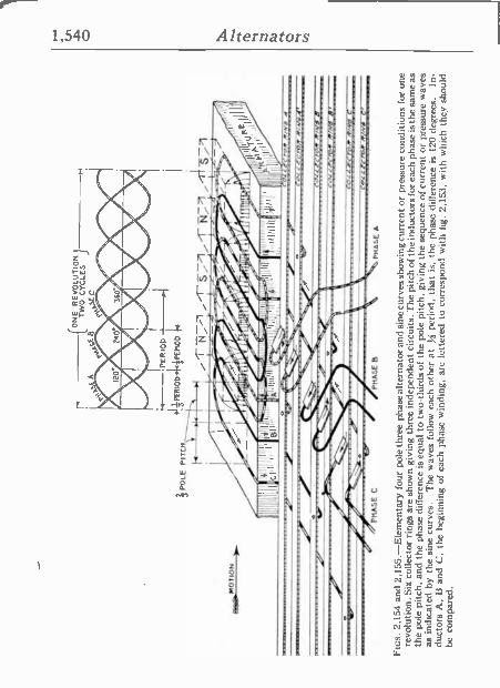
r - (O
NE
R
EV
OLU
TIO
N
TW
O C
YC
LES
}
a .e
'IPE
RIO
D
IOD
Í+3P
EP
IOD
4f
P
OLE
P
ITC
H
Í'"¡
171-
71
/rf
.i71
t t -,
. =
{r.s
.o.
. `i ili
li'.i7
I tE
>
>
_ 'P
HA
SE
C
'
. P
HA
SE
B
PHA
SE
A
Ftc
s. 2
,154
an
d 2,
155.
-Ele
men
tary
fou
r po
le th
ree
phas
e al
tern
ator
and
sin
e cu
rves
sho
win
g cu
rren
t or
pres
sure
con
ditio
ns f
or o
ne
revo
lutio
n. S
ix c
olle
ctor
rin
gs a
re s
how
n gi
ving
thr
ee i
ndep
ende
nt c
ircui
ts.
The
pitc
h of
the
indu
ctor
s fo
r ea
ch p
hase
is
the
sam
e as
th
e po
le p
itch,
and
the
pha
se d
iffer
ence
is e
qual
to
two-
third
s of
the
pol
e pi
tch,
giv
ing
the
sequ
ence
of
curr
ent
or p
ress
ure
wav
es
as in
dica
ted
by t
he s
ine
curv
es.
The
wav
es f
ollo
w e
ach
othe
r at
;f
per
iod,
tha
t is
, th
e ph
ase
diffe
renc
e is
12
0 de
gree
s.
In-
duct
ors
A,
II an
d C
, th
e be
ginn
ing
of e
ach
phas
e w
indi
ng,
arc
lette
red
to c
orre
spon
d w
ith f
ig.
2,15
3, w
ith w
hich
th
ey s
houl
d be
com
pare
d.
0
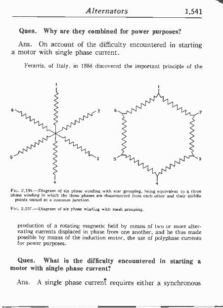
Alternators 1,541
Ques. Why are they combined for power purposes?
Ans. On account of the difficulty encountered in starting a motor with single phase current.
Ferarris, of Italy, in 1888 discovered the important principle of the
4 4
FIG. 2,156.-Diagram of six phase winding with star grouping, being equivalent to a three phase winding in which the three phases are disconnected from each other and their middle
points united at a common junction.
Ftc. 2,157.-Diagram of six phase winding with mesh grouping.
production of a rotating magnetic field by means of two or more alter- nating currents displaced in phase from one another, and he thus made possible by means of the induction motor, the use of polyphase currents for power purposes.
Ques. What is the difficulty encountered in starting a motor with single phase current?
Ans. A single phase current requires either a synchronous
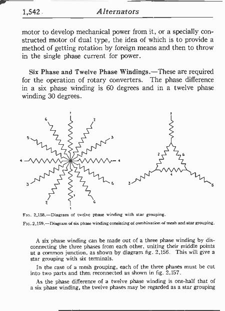
1,542 . Alternators
motor to develop mechanical power from it, or a specially con- structed motor of dual type, the idea of which is to provide a method of getting rotation by foreign means and then to throw in the single phase current for power.
Six Phase and Twelve Phase Windings.-These are required for the operation of rotary converters. The phase difference in a six phase winding is 60 degrees and in a twelve phase winding 30 degrees.
FIG. 2,158.-Diagram of twelve phase winding with star grouping.
Ftc. 2,159.-Diagram of six phase a inding consisting of combination of mesh and star grouping.
A six phase winding can be made out of a three phase winding by dis- connecting the three phases from each other, uniting their middle points at a common junction, as shown by diagram fig. 2,156. This will give a star grouping with six terminals.
In the case of a mesh grouping, each of the three phases must be cut into two parts and then reconnected as shown in fig. 2,157.
As the phase difference of a twelve phase winding is one-half that of a six phase winding, the twelve phases may be regarded as a star grouping
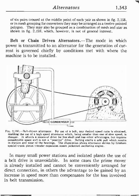
Alternators 1,543
of six pairs crossed at the middle point of each pair as shown in fig. 2,158, or in mesh grouping for converters they may be arranged as a twelve pointed polygon. They may also be grouped as a combination of mesh and star as shown in fig. 2,159, which, however, is not of general interest.
Belt or Chain Driven Alternators.-The mode in which power is transmitted to an alternator for the generation of cur- rent is governed chiefly by conditions met with where the machine is to be installed.
Ftc. 2,160.-Belt-driven alternator. By use of a belt, any desired speed ratio is obtained, enabling the use of a high speed alternator which, being smaller than one of slow speed, is cheaper. It affords a means of drive for line shaft and has other advantages, but requires considerable space and is not a "positive" drive. Belting exerts a side pull which results in friction and wear of the bearings. The illustration shows alternator driven by Graham special trunk piston transfer expansion steam jacketted oscillating engine.
In many small power stations and isolated plants the use of a belt drive is unavoidable. In some cases the prime mover is already installed and cannot be conveniently arranged for direct connection, in others the advantage to he gained by an increase in speed more than compensates for the loss involved in belt transmission.
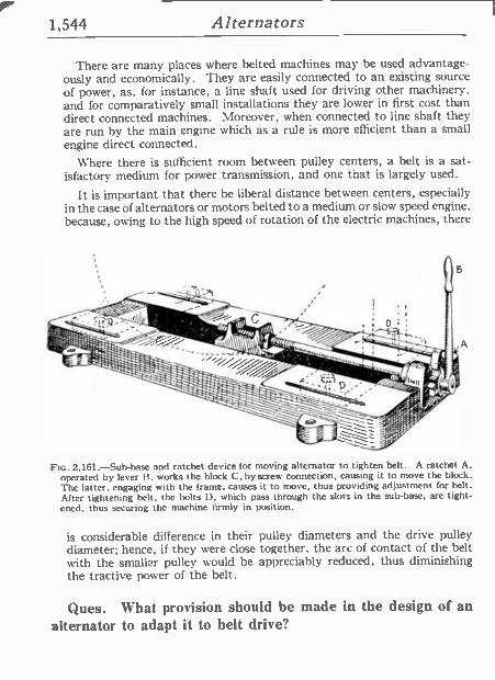
1,544 Alternators
There are many places where belted machines may be used advantage- ously and economically. They are easily connected to an existing source of power, as, for instance, a line shaft used for driving other machinery, and for comparatively small installations they are lower in first cost than direct connected machines. Moreover, when connected to line shaft they are run by the main engine which as a rule is more efficient than a small engine direct connected.
Where there is sufficient room between pulley centers, a belt is a sat- isfactory medium for power transmission, and one tnat is largely used.
It is important that there be liberal distance between centers, especially in the case of alternators or motors belted to a medium or slow speed engine, because, owing to the high speed of rotation of the electric machines, there
FIG. 2,161.-Sub-base and ratchet device (or moving alternator to tighten belt. A ratchet A, operated by lever 13, works the block C, by screw connection, causing it to move the block. The latter, engaging with the frame, causes it to move, thus providing adjustment for belt. After tightening belt. the bolts ll, which pass through the slots in the sub -base, are tight- ened, thus securing the machine firmly in position.
is considerable difference in their pulley diameters and the drive pulley diameter; hence, if they were close together, the arc of contact of the belt with the smaller pulley would be appreciably reduced, thus diminishing the tractive power of the belt.
Ques. What provision should be made in the design of an alternator to adapt it to belt drive?
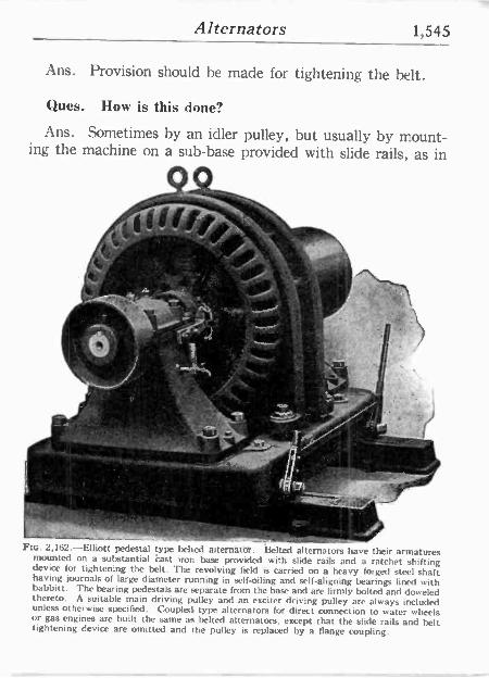
Alternators 1,545
Ans. Provision should be made for tightening the belt.
Ques. How is this done?
Ans. Sometimes by an idler pulley, but usually by mount- ing the machine on a sub -base provided with slide rails, as in
rs
.
r Ftc. 2,162.-Elliott pedestal type belied aiternater. Belted alternators have their armatures mounted on a substantial east iron base provided with slide rails and a ratchet shifting device for tightening the belt. The revolving field is carried on a heavy forged steel shaft having journals of large diameter running in self -oiling and self -aligning bearings lined with babbitt. The bearing pedestals are separate from the base and are firmly bolted and doweled thereto. A suitable main driving pulley and an exciter driving pulley are always included unless otherwise specified. Coupled type alternators for direct connection to water wheels or gas engines are built the same as belted alternators, except that the slide rails and belt tightening device are omitted and the pulley is replaced by a flange coupling.
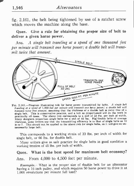
1,546 Alternators
fig. 2,161, the belt being tightened by use of a ratchet screw which moves the machine along the base.
Ques. Give a rule for obtaining the proper size of belt to deliver a given horse power.
Ans. A single belt traveling at a speed of one thousand feel per minute will transmit one horse power; a double bell will trans- mit twice that amount.
FIG. 2,1113.-Diagram illustrating rule for horse power transmitted by belts. A single bell
traveling al a speed of 1,000 feet per minute will transmit one hors.. power; a double bell will tiansmit twice that amount, assuming that the thickness of a double belt is twice that of a
single belt. This is conservative practice. and a belt so proportioned will do the work in practically all cases. The above rule corresponds to a pull of .4 lbs. per inch of width. Many designers proportion single belts for a pill! of 45 lbs. Fa¡'double belts of average thickness, some writers say that the transmitting efficiency is tothat of single belts as 10
is to 7. This should not be applied to the above rule for single belts, as it will give an un- necessarily large belt.
This corresponds to a working strain of 33 lbs. per inch of width for
single belt, or 66 lbs. for double belt. Many writers give as safe practice for single belts in good condition a
working tension of 45 lbs. per inch of width.
Ques. What is the best speed for maximum belt economy?
Ans. From 4,000 to 4,500 feet per minute.
Example.-What is the proper size of double belt for an alternator having a 16 inch pulley, and which requires 50 horse power to drive it at 1,000 revolutions per minute full load?
Alternators 1,547
The velocity of the belt is
circumference in feet Xrevolutions = feet per minute
12X3.1416 X 1,000 = 4,188.
Horse power transmitted per inch width of double belt at 4,188 feet speed
2X4.188_8.38. 1,000
Width of double belt for 50 horse power
50=8.38=5.97, say 6 inch.
Ques. What are the advantages of chain drive?
Ans. The space required is much less than with belt drive, as the distance between centers may be reduced to a minimum. It is a positive drive, that is, there can be no slip. Less liability of becoming detached, and, because it is not dependent on frictional contact, the diameters of the sprockets may be much less than pulley diameter for belt drive.
Ques. What are some objections?
Ans. A lubricant is required for satisfactory operation, which causes more or less dirt to collect on the chain, requiring frequent cleaning; climbing of teeth when links and teeth be- come worn; noise and friction.
Direct Connected Alternators.-There are a large number of cases where economy of space is of prime importance, and to meet this condition the alternator and engine are direct con- nected, meaning, that there is no intermediate gearing such as belt, chain, etc., between engine and alternator.
One difficulty encountered in the direct connection of engine and alter- nator is the fact that the most desirable rotative speed of the engine is
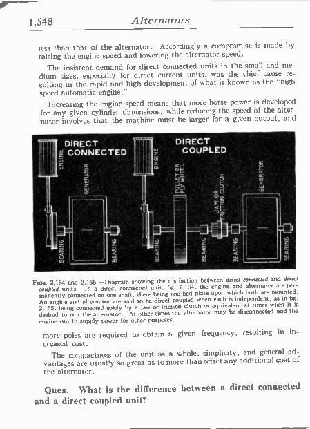
1,548 Alternators
O
z
less than that of the alternator. Accordingly a compromise is made by
raising the engine speed and lowering the alternator speed.
The insistent demand for direct connected units in the small and me-
dium sizes, especially for direct current units, was the chief cause re-
sulting in the rapid and high development of what is known as the "high speed automatic engine."
Increasing the engine speed means that more horse power is developed
for any given cylinder dimensions, while reducing the speed of the alter-
nator involves that the machine must be larger for a given output, and
DIRECT - a
; DIRECT P
CONNECTED ;, ¡ ° - COUPLED z II z W
"
W óW
.fY ' _ ____ . J; .
-
W j '
0 ' ' 11-L. - trd OZ
1.2 QV i-. K Il '
FIGS. 2,164 and 2,165.-Diagram showing the distinction between direct connected and direct
coupled units. In a direct connected unit, fig. 2,164, the engine and alternator are per-
manently connected on one shaft, there being one bed plate upon which both are mounted.
An engine and alternator are said to he direct coupled when each is independent, as in fig.
2,165, being connected solely by a jaw or friction clutch or equivalent at.times when it' is
desired to run the alternator. At other times the alternator may be disconnected and the
engine run to supply power for other purposes.
more poles are required to obtain a given frequency, resulting ín In-
creased cost.
The compactness of the unit as a whole, simplicity, and general ad-
vantages are usually so great as to more than offset any additional cost of
the alternator.
Ques. What is the difference between a direct connected
and a direct coupled unit?
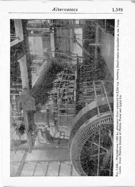
Alternators 1,549
- N.
1/, r4 " - 1 - 1-7~
-. .,..a... Sfa. y^;r'=.^
. ' ,
.......4.:...
1
`!- . . .yi!' ,,jC.t '
k144./
111, ' S I? S,:: :is _
- + - ..
_ °~ -
-
Gr ,
_.+.Q
`-
. .'11.-----11, . _
° ',...?1 -
c¢.i, . ñ.0
4;,
,!
, dl ;t:411."J'=4? t. ¢, ; 6_. ', i,-
yK,-
/.19.- .'- Er r ;,/d "'''.
ai, hg 7... '/ , , u_ 'e
I _ , o ." * r 1
,1-,,
""-- ._'; 1_ry
-;; .
.. t`c
144
J.
u
A
^ . 5
-
11.'1 .w
d úm 1.2
gm + H
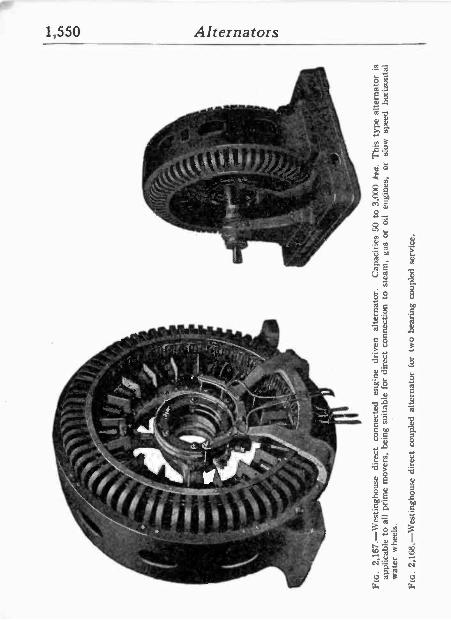
oya
; , !
2,16
7.-W
estin
ghou
se d
irect
co
nnec
ted
engi
ne
driv
en
alte
rnat
or.
Cap
aciti
es 5
0 to
3,0
00 k
oa.
Thi
s ty
pe a
ltern
ator
is
appl
icab
le t
o al
l pr
ime
mov
ers,
bei
ng s
uita
ble
for
dire
ct c
onne
ctio
n to
st
eam
, ga
s or
oil
engi
nes,
or
sl
ow
spee
d ho
rizon
tal
wat
er w
heel
s.
Fc. 2
,168
.-W
estin
ghou
se d
irect
cou
pled
alte
rnat
or f
or
two
bear
ing
coup
led
serv
ice.
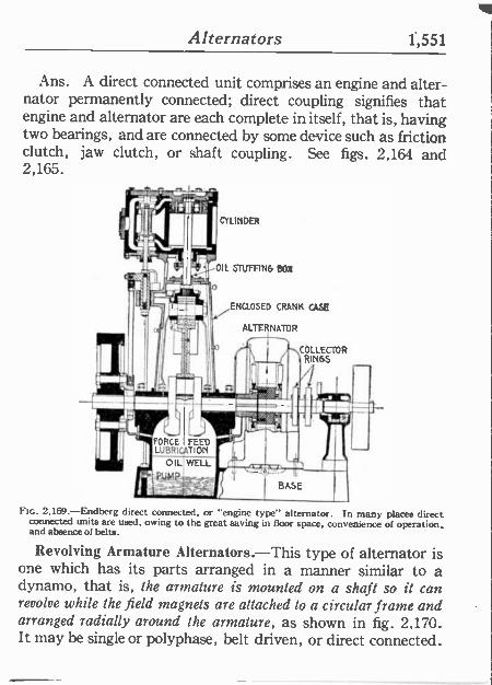
Alternators 1,551
Ans. A direct connected unit comprises an engine and alter- nator permanently connected; direct coupling signifies that engine and alternator are each complete in itself, that is, having two bearings, and are connected by some device such as friction clutch, jaw clutch, or shaft coupling. See figs. 2,164 and 2,165.
CYLINDER
OIL STUFFING 80X
ENCLOSED CRANK CASE
ALTERNATOR
n RINSSTOR
1-
BASE
Fuc. 2,169 -Endberg direct connected, or "engine type" alternator. In many places direct connected units are used, owing to the great saving in floor space, convenience of operation. and absence of belts.
Revolving Armature Alternators.-This type of alternator is one which has its parts arranged in a manner similar to a dynamo, that is, the armature is mounted on a shaft so it can revolve while the field magnets are attached to a circular frame and arranged radially around the armature, as shown in fig. 2,170. It may be single or polyphase, belt driven, or direct connected.
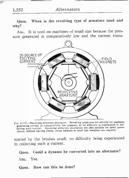
1,552 Alternators
Ques. When is the revolving type of armature used and why? .
Ans. It is uFed on machines of small size because the pres-
sure generated is comparatively low and the current trans -
TO SOURCE OF EXCITING CURRENT
FIELD MAGNETS
Ftc. 2,170.-Revolving armature alternator. Revolving armatures are suitable for machines
generating current at comparatively low pressure, as no difficulty is experienced in col-
lecting such current. Revolving armature alternators are also suitable for small power
plants, isolated lighting plants, where medium or small size machines are required.
mated by the brushes small, no difficulty being experienced
in collecting such a current.
Ques. Could a dynamo be converted into an alternator?
Ans. Yes.
Ques. How can this be done?
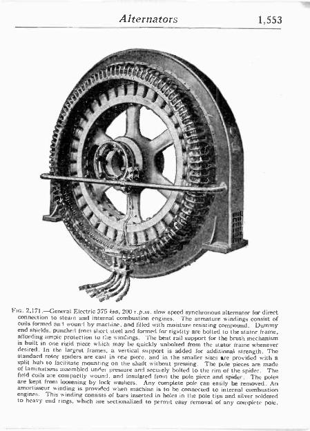
Alternators 1,553
. .
ti
HG:ea.-,, ., "
,1L
Ftc. 2,171.-General Electric 375 kva, 200 r.p.m. slow speed synchronous alternator for direct connection to steam and internal combustion engines. The armature windings consist of coils formed ani sound by machine, and filled with moisture resisting compound. Dummy end shields, punched from sheet steel and formed for rigidity are bolted to the stator frame, affording ample protection to the windings. The bent rail support for the brush mechanism is built in one rigid piece which may be quickly unbolted from the stator frame whenever desired. In the largest frames, a vertical support is added for additional strength. The standard rotor spiders are cast in one piece, and in the smaller sizes are provided with a split huh to facilitate mounting on the shaft without pressing. The pole pieces are made of laminations assembled unrter pressure and securely bolted to the rim of the spider. The field coils are compactly wound, and insulated from the pole piece and spider. The poles are kept from loosening by lock washers. Any complete pole can easily be removed. An amortisseur winding is provided when machine is to be connected to internal combustion engines. This winding consists of bars inserted in holes in the pole tips and silver soldered to heavy end rings, which are sectionalized to permit easy removal of any complete pole.
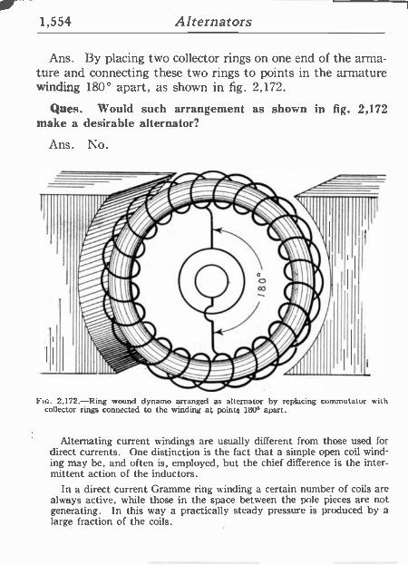
1,554 Alternators
Ans. By placing two collector rings on one end of the arma- ture and connecting these two rings to points in the armature winding 180° apart, as shown in fig. 2,172.
Ques. Would such arrangement as shown make a desirable alternator?
Ans. No.
in fig. 2,172
Fic. 2,172.-Ring wound dynamo arranged as alternator by replacing commutator with collector rings connected to the winding at points 1800 apart.
Alternating current windings are usually different from those used for direct currents. One distinction is the fact that a simple open coil wind- ing may be, and often is, employed, but the chief difference is the inter- mittent action of the inductors.
In a direct current Gramme ring winding a certain number of coils are always active, while those in the space between the pole pieces are not generating. In this way a practically steady pressure is produced by a large fraction of the coils.
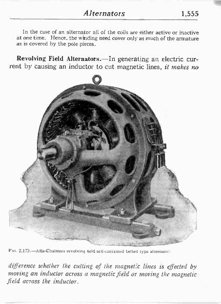
Alternators 1,555
In the case of an alternator all of the coils are either active or inactive at one time. Hence, the winding need cover only as much of the armature as is covered by the pole pieces.
Revolving Field Alternators.-In generating an electric cur- rent by causing an inductor to cut magnetic lines, it makes no
%;, . S , . . r 1_
.Á
[11
_-...m..-..-.:. Fin. 2,173.-Allis-Chalmers revolving geld sell -contained belted type alternato-.
difference whether the cutting of the magnet'c lines is effected by moving an inductor across a magnetic field or moving the magnetic field across the inductor.
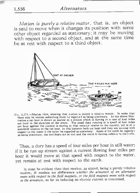
1,556 Alternators
11'lotion is purely a relative matter, that is, an object is said to move when it changes its position with some other object regarded as stationary; it may he moving with respect to a second object, and at the same time be at rest with respect to a third object.
BOAT AT ANCHOR
1; TIDE 4 MILES PER MOOR ____>, :,--_-_
-9--,
R1 '- -- TC.` -,.-_--SPEEDOF DORY ----- __-
-
- MttEzPER HOUR.- -,,,z__-
Ftc. 2,174.-Marine view, showing that notion is purely a re:ative matter. In order that there may be motion something must I e regarcel as being stationary. In the above illus-
tration a cat boat is shown at anchor in a stream which is flowing at a rate of four miles
per hour in the direction of the arrow. The small dory running at a speed of four miles
per hour against the current is mooing at that velocity relative to the current, yet is at a
standstill relative to the cat boat. In this instance both cat boat and gory are moving with respect to the water if the latter be regarded as stationary. Again if the earth be regarde 1
as being stationary, the two boats are at rest and the water is moving relative to the earth.
Thus, a dory has a speed of four miles per hour in still water; if it be run up stream against a current [lowing four miles per
hour it would move at that speed with respect to the water, yet remain at rest with respect to the earth.
It must be evident then that motion, as stated, being a purely relative matter, it rakes no difference whether the armature of an alternator
move with respect lo the field magnets, or the field magnets move with respect
lo the armature, so far as inducing an electric current is concerned.
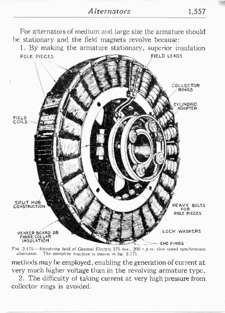
Alternators 1,557
For alternators of medium and large size the armature should be stationary and the field magnets revolve because:
1. By making the armature stationary, superior insulation POLE PIECES rafts +
...1");.
.; ` ,
FIELD LEADS
ZOLLECTOR RINGS
CYLINDRIC
1 ADAPTER
e COILS"---..,./ iv!~ M 1 r 1 111"
i,
SPLIT HUB CONSTRUCTION
VENEER BÓARD OR s` LOCK WASHERS
FIBRE COLLAR INSULATION
END SINGS FIG. 2,175.-Revolving field of General Electric 375 kva., 200 r.p.m.slow speed synchronous
alternator. The complete machine is shown in fig. 2,171.
methods may be employed, enabling the generation of current at very much higher voltage than in the revolving armature type.
2. The difficulty of taking current at very high pressure from collector rings is avoided.
m
HEAVOYR BOLTS
DOLE PIECES
FIELD XII it
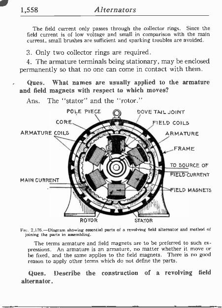
1,558 Alternators
The field current only passes through the collector rings. Since the field current is of low voltage and small in comparison with the main current, small brushes are sufficient and sparking troubles are avoided.
3. Only two collector rings are required. 4. The armature terminals being stationary, may be enclosed
permanently so that no one can come in contact with them.
Ques. What names are usually applied to the armature and field magnets with respect to which moves?
Ans. The "stator" and the "rotor." POLE PIECE
CORE\ ARMATURE COILS
MAIN CURRENT
\e/ DOVE TML JOINT jr Fl ELD IELD COILS
ARMATURE
ROTOR STATOR
IELD MAGNETS
FIG. 2.176.-Diagram showing essential parts of a revolving field alternator and method of joining the parts in assembling.
The terms armature and field magnets are to he preferred to such ex- pressions. An armature is an armature, no matter whether it move or be fixed, and the same applies to the field magnets. There is no good reason to apply other terms which do not define the parts.
Ques. Describe the construction of a revolving field alternator.
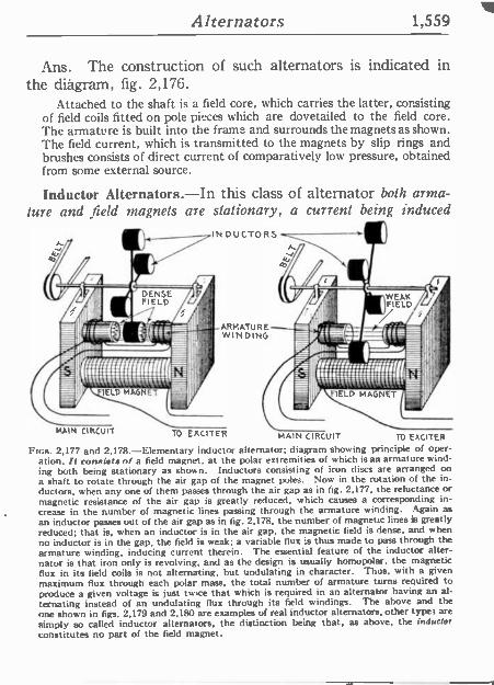
Alternators 1,559
Ans. The construction of such alternators is indicated in the diagram, fig. 2,176.
Attached to the shaft is a field core, which carries the latter, consisting of field coils fitted on pole pieces which are dovetailed to the field core. The armature is built into the frame and surrounds the magnets as shown. The field current, which is transmitted to the magnets by slip rings and brushes consists of direct current of comparatively low pressure, obtained from some external source.
Inductor Alternators.-In this class of alternator both arma- ture and field magnets are stationary, a current being induced
.ARMATURE WINDING
MAIN CIRCUIT TO EXCITER MAIN CIRCUIT To EXCITER
FIGS. 2,177 and 2,178.-Elementary inductor alternator; diagram showing principle of oper- ation. It consists of a field magnet, at the polar extremities of which is au armature wind- ing both being stationary as shown. Inductors consisting of iron discs are arranged on a shaft to rotate through the air gap of the magnet poles. Now in the rotation of the in- ductors, when any one of them passes through the air gap as in fig. 2,177, the reluctance or magnetic resistance of the air gap is greatly reduced, which causes a corresponding in- crease in the number of magnetic lines passing through the armature winding. Again as
an inductor passes out of the air gap as in fig. 2,178, the number of magnetic lines is greatly reduced; that is, when an inductor is in the air gap, the magnetic field is dense, and when no inductor is in the gap, the field is weak; a variable flux 's thus made to pass through the
armature winding, inducing current therein. The essential feature of the inductor alter- nator is that iron only is revolving, and as the design is usually homopolar, the magnetic flux in its field coils is not alternating, but undulating in character. Thus, with a given maximum flux through each polar mass, the total number of armature turns required to produce a given voltage is just twice that which is required in an alternator having an al- ternating instead of an undulating flux through its field windings. The above and the one shown in figs. 2,179 and 2,180 are examples of real inductor alternators, other types are
simply so called inductor alternators, the distinction being that, as above, the inductor constitutes no part of the field magnet.
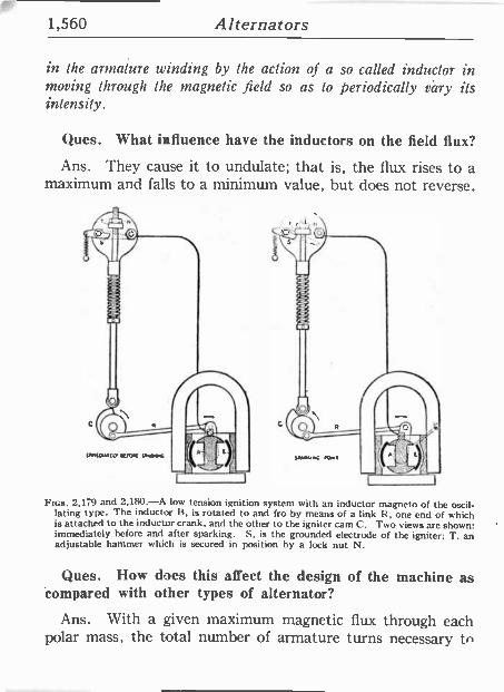
1,560 Alternators
in the armature winding by the action of a so called inductor in moving through the magnetic field so as to periodically vary its intensity.
Ques. What influence have the inductors on the field flux?
Ans. They cause it to undulate; that is, the flux rises to a maximum and falls to a minimum value, but does not reverse.
FIGS. 2,179 and 2,180.-A low tension ignition system with an inductor magneto of the oscil- lating type. The inductor B, is rotated to and fro by means of a link it, one end of which is attached to the inductor crank, and the other to the igniter cam C. Two views are shown: immediately before and after sparking. S, is the grounded electrode of the igniter; T. an adjustable hammer which is secured in position by a lock nut N.
Ques. How does this affect the design of the machine as 'compared with other types of alternator?
Ans. With a given maximum magnetic flux through each polar mass, the total number of armature turns necessary VI
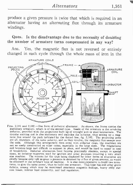
Alternators 1,561
produce a given pressure is twice that which is required in an alternator having an alternating flux through its armature windings.
Ques. Is the disadvantage due to the necessity of doubling the number of armature turns compensated in any way?
Ans. Yes, the magnetic flux is not reversed or ertirely changed in each cycle through the whole mass of iron in the
PROJECTI POLES
ARMATURE COILS
FRAME -a N6 4/0\IICr 1" kl~POLE
Í tl
II S,:IIIIIII IIIII
; u;n nrearr';I
ARMATURE COIL
INDUCTOR
SHAFT
Floe. 2,181 and 2,182.-One form of inductor alternator. As shown, the frame carries the stationary armature, which is of the slotted type. Inside of the armature is the revolving inductor, provided with the projections built up of wrought iron or steel laminations. The circular exciting coil is also stationary and encircles the inductor, thus setting up a mag- netic flux around the path indicated by the dotted line, fig. 2,182. The projecting poles are all, therefore, of the same polacty, and as they revolve, the magnetic flux sweeps over the coils. Although this arrangement does away with collector rings, the machines are not so easily constructed as other types, especially in the large sizes. The magnetizing coil becomes large and difficult to support in place, and would be hard to repair in case of breakdown. Inductor alternators have become practically obsolete, except in special cases, as inductor magnetos used for ignition and other purposes requiring a very small size machine. The reasons for the type being displaced by other forms of alternator are chiefly because only half as great a pressure is obtained by a flux of given amount, as would he obtained in the ordinary type of machine. It is also more expensive to build two arma- tures, to give the same power, than to build one armature. This type has still other grave defects, among which may be mentioned enormous magnetic leakage, heavy eddy cur- rent losses, inferior heat emissivity, and bad regulation.
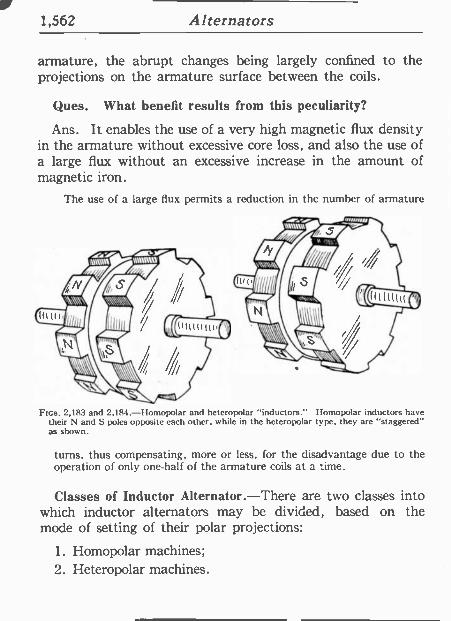
1,562 Alternators
armature, the abrupt changes being largely confined to the projections on the armature surface between the coils.
Ques. What benefit results from this peculiarity?
Ans. It enables the use of a very high magnetic flux density in the armature without excessive core loss, and also the use of a large flux without an excessive increase in the amount of magnetic iron.
The use of a large flux permits a reduction in the number of armature
aNIPZ0r ataittt ®
calif (0awartr n
i
Fins. 2,183 and 2,184.-Homopolar and heteropolar "inductors." Homopolar inductors have their N and S poles opposite each other, while in the heteropolar type, they arc "staggered" as shown.
turns, thus compensating, more or less, for the disadvantage due to the operation of only one-half of the armature coils at a time.
Classes of Inductor Alternator.-There are two classes into which inductor alternators may be divided, based on the mode of setting of their polar projections:
1. Homopolar machines; 2. Heteropolar machines.
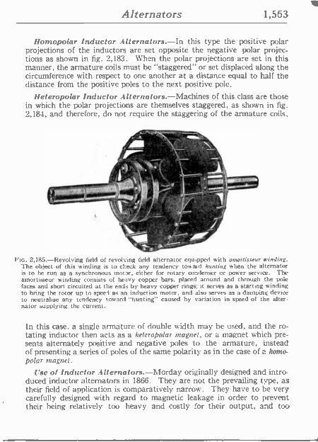
Alternators 1,563
Ilomopolar Inductor Alternators.-In this type the positive polar projections of the inductors are set opposite the negative polar projec- tions as shown in fig. 2,183. When the polar projections a -e set in this manner, the armature coils must be "staggered" or set displaced along the circumference with respect to one another at a distance equal to half the distance from the positive poles to the next positive pole.
Ileteropolar Inductor Alternators.-Machines of this class are those in which the polar projections are themselves staggered, as shown in fig. 2,184, and therefore, do not require the staggering of the armature coils.
A l l 17
NEW El
T,..1.% ----.T,..1.%----.
FIG. 2,185.-Revolving field of revolving field alternator equipped with amortisseur winding. The object of this winding is to check any tendency toward hunting when the alternator is to be run as a synchronous motor, either for rotary condenser or power service. The amortisseur winding consists of heavy copper bars, placed around and through the pole faces and short circuited at the ends by heavy copper rings; it serves as a starting winding to bring the rotor up to speed as an induction motor, and also serves as a damping device to neutralize any tendency toward "hunting" caused by variation in speed of the alter- nator supplying the current.
In this case, a single armature of double width may be used, and the ro- tating inductor then acts as a iteteropolar magnet, or a magnet which pre- sents alternately positive and negative poles to the armature, instead of presenting a series of poles of the same polarity as in the case of a home - polar magnet.
Use of Inductor Alternators.-Morday originally designed and intro- duced inductor alternators in 1866. They are not the prevailing type, as their field of application is comparatively narrow. They have to be very carefully designed with regard to magnetic leakage in order to prevent their being relatively too heavy and costly for their output, and too
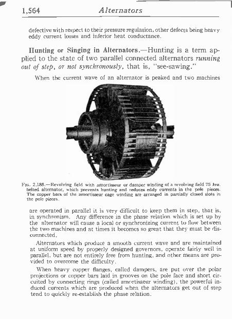
1,564 Alternators
defective with respect to their pressure regulation, other defects being heavy eddy current losses and inferior heat conductance.
Hunting or Singing in Alternators.-Hunting is a term ap- plied to the state of two parallel connected alternators running out of step, or not synchronously, that is, "see -sawing."
When the current wave of an alternator is peaked and two machines
ii.o
_ 1,10
ft .f, - _-o_w ,
1
-A
irOf - - z
FIG. 2.186.-Revolving field with amortisseur or damper winding of a revolving field 75 kou. belted alternator, which prevents hunting and reduces eddy currents in the pole pieces. The copper bars of the amortisseur cage winding are arranged in partially closed slots in the pole pieces.
are operated in parallel it is very difficult to keep them in step, that is, in synchronism. Any difference in the phase relation which is set up by the alternator will cause a local or synchronizing current to flow between the two machines and at times it becomes so great that they must be dis- connected.
Alternators which produce a smooth current wave and are maintained at uniform speed by properly designed governors, operate fairly well in parallel, but are not entirely free from hunting, and other means are pro- vided to overcome the difficulty.
When heavy copper flanges, called dampers, are put over the polar projections or copper bars laid in grooves on the pole face and short cir- cuited by connecting rings (called amortisseur winding), the powerful in- duced currents which are produced when the alternators get out of step tend to quickly re-establish the phase relation.
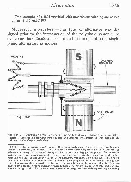
Alternators 1,565
Two examples of a field provided with amortisseur winding are shown in figs. 2,185 and 2,186.
Monocyclic Alternators.-This type of alternator was de- signed prior to the introduction of the polyphase systems, to overcome the difficulties encountered in the operation of single phase alternators as motors.
RHEOSTAT
REVOLVING ARMATURE
STATIONARY FIELD
3 4t LINE
FIG. 2,187. -Connection diagram of General Electric belt driven revolving armature alter- nator. Illustrations showing construction and general appearance of this machine are shown in the chapter following.
NOTE. Antorlixaeur findings are often erroneously called "squirrel cage" windings on account of similarity of construction. The latter term should he reserved for its proper sig- nificance as being the name of the type of armature winding generally used for induction motors, the name being suggested by the resemblance of the finished armature to the wheel of a squirrel cage. A comparison of figs. 2,186 and 2.632 a ill show the distinct ion. In a s'iuirrel cage winding there is a large number of bars uniformly spaced; an amortisseur winding con- sists of a comparatively small number of bars, usually unevenly spaced; that is, they are divided into groups with considerable space between the grou ]s. as in fig. 2,186, and less pro- nounced in fig. 2,185. The bars are short circuited by rings the same as in squirrel cage winding.
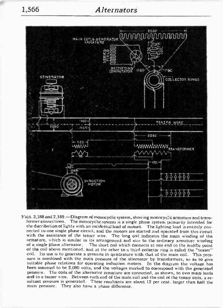
1,566 Alternators.
2080 ---- - MA,N CO'LS GENERATOR
ARMA1URE
A w W
Wy ) - a
REC COMMTUTÁTOR . If60
.-- `116C.
COdLECTOR RINGS
,_¢ f L _. . I60. '-_12A60___,'J " i
1,
". I
' 520
V INDUCTION
MOTOR
TEAZER WIRE
-/k-.¡+v " """'IMAIM1'RANSFORMER.
FIGS. 2,188 and 2,189.-Diagram of monocyclic system, showing monocyclc armature and trans- former connections. The monocyclic system is a single phase system primarily intended for the distribution of lights with an incidental load of motors. The lighting load is entirely con- nected to one single phase circuit, and the motors are started and operated from this circuit with the assistance of the teazer wire. The long coil indicates the main winding of the armature, which is similar in its arrangement and size to the ordinary armature winding of a single phase alternator. The short coil which connects at one end to the middle point of the coil above mentioned, and at the other to a third collector ring is called the "teazer" coil. Its use is to generate a pressure in quadrature with that of the main coil. This pres- sure is combined with the main pressure of the alternator by transformers, so as to give suitable phase relations for operating induction motors. In the diagram the voltage has been assumed to be 2,080 volts, and the voltages marked to correspond with the generated pressure. The coils of the alternator armature are connected, as shown, to two main leads and to a teazer wire. Between each end of the main coil and the end of the teazer coils, a re- sultant pressure is generated. These resultants are about 12 per cent. larger than half the main pressure. They also have a phase difference.
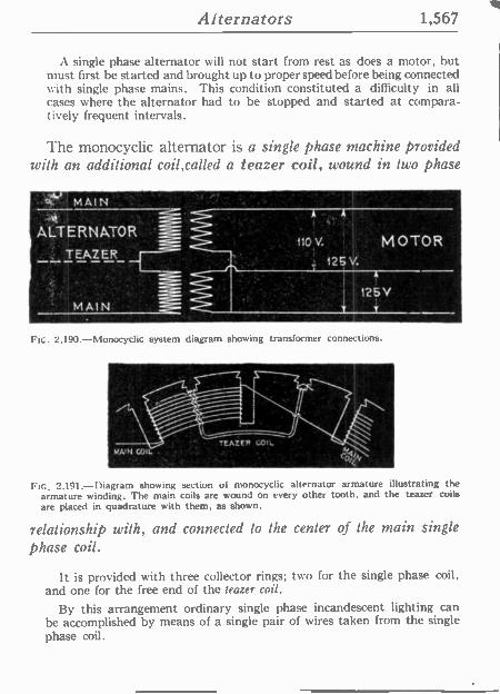
Alternators 1,567
A single phase alternator will not start from rest as does a motor, but must first be started and brought up to proper speed before being connected with single phase mains. This condition constituted a difficulty in all cases where the alternator had to be stopped and started at compara- tively frequent intervals.
The monocyclic alternator is a single phase machine provided with an additional coil,called a teazer coil, wound in two phase
7 MAIN
'ALTERNATOR : o MOTOR
:; , TEAZER_ +. 121V.
A
125V ¡MAIN - o. . ,
Fle. 1,190 -Monocyclic system diagram showing transformer connections.
FiG. 2,191.-Diagram showing section of monocyclic alternator armature illustrating the armature winding. The main coils are wound on every other tooth, and the teazer coils are placed in quadrature with them, as shown.
relationship with, and connected to the center of the main single phase coil.
It is provided with three collector rings; two for the single phase coil, and one for the free end of the teazer coil.
By this arrangement ordinary single phase incandescent lighting can be accomplished by means of.a single pair of wires taken from the single phase coil.
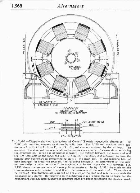
1,568 Alternators
SEPARATELY EXCITED FIELD
VsNW/VV` STATIONARY SHUNT
OR COMPOUNDING RHEOSTAT
31 G5 -COLLECTOR RINGS
LINE
p COM MUTATOR
Fin. 2,192.-Diagram showing connections of General Electric monocyclic alternator. ror 2,300 volt machine, connect as shown by solid lines. For 1,150 volt machine, omit con- nections A to 13, C to D. E to F, and G to H, and connect as shown by dotted lines. The armature of a stanc'ard monocyclic alternator rotates in a counter clockwise direction facing the commutator. When the alternator is loaded, the voltage between the teazer coil and the two terminals of the main coil may he different; therefore, it is necessary to have the commutator connected in corresponding ends of the main roil. If the machine has not been arranged for clockwise rotation, the following change in the connections on the com- mutator -collector must be made if the machine is to be run in parallel with another. Fig. 2,193 shows the connections of monocyclic alternators. In fig. 2.192, the studs on the commutator -collector marked I and ti are the terminals of the main coil. These should he reversed. The numbers are stamped on the ends of the stud and may be seen with the assistance of a mirror. By referring to this diagram it is a simple matter to trace out the connections with a magneto, after the armature leads are disconnected and the brushes raised.
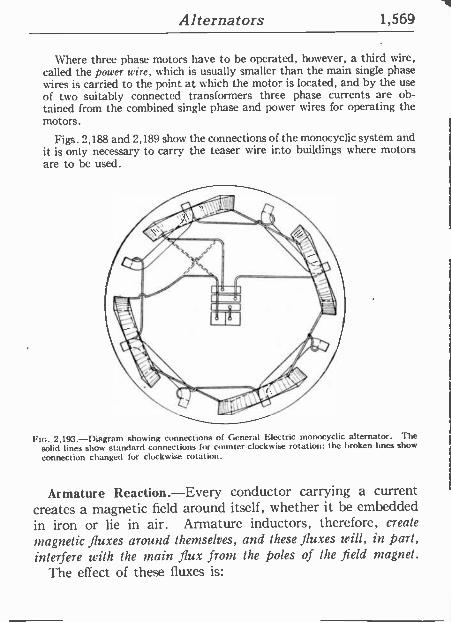
Alternators 1,569
Where three phase motors have to be operated, however, a third wire, called the power wire, which is usually smaller than the main single phase wires is carried to the point at which the motor is located, and by the use
of two suitably connected transformers three phase currents are ob- tained from the combined single phase and power wires for operating the motors.
Figs. 2,188 and 2,189 show the connections of the monocyclic system and it is only necessary to carry the teaser wire into buildings where motors are to be used.
Fw. 2,193.-Diagram showing connections of General Electric monocyclic alternator. The solid lines show standard connections for counter -clockwise rotation; the broken lines show
connection changed for clockwise rotation.
Armature Reaction.-Every conductor carrying a current creates a magnetic field around itself, whether it be embedded in iron or lie in air. Armature inductors, therefore, create
magnetic fluxes around themselves, and these fluxes will, in part, interfere with the grain flux from the poles of the field magnet.
The effect of these fluxes is:
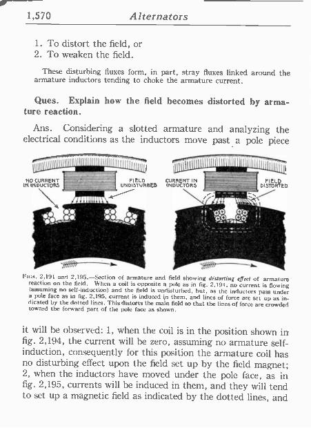
1,570 Alternators
1. To distort the field, or 2. To weaken the field.
These disturbing fluxes form, in part, stray fluxes linked around the armature inductors tending to choke the armature current.
Ques. Explain how the field becomes distorted by arma- ture reaction.
Ans. Considering a slotted armature and analyzing the electrical conditions as the inductors move past a pole piece
ro,"""""""--77"11771777'.7 wIllnnuiplll
I Iil I I
I
NO CURRENT IN INDUCTORS
FIELD CURRENT IN UNDISTURBED INDUCTORS
FIELD DISTORTED
Fies. 2,191 and 2,195.-Section of armature and field showing distorting effect of armature reaction on the field. When a coil is opposite a pole as in fig. 2,194, no current is flowing (assuming no self-induction) and the field is undisturbed, but, as the inductors pass under a pole face as in fig. 2,195, current is induced in them, and lines of force arc set up as in- dicated by the dotted lines. This distorts the main field so that the lines of force are crowded toward the forward part of the pole face as shown.
it will be observed: 1, when the coil is in the position shown in fig. 2,194, the current will be zero, assuming no armature self- induction, consequently for this position the armature coil has. no disturbing effect upon the field set up by the field magnet;. 2, when the inductors have moved under the pole face, as in fig. 2,195, currents will be induced in them, and they will tend to set up a magnetic field as indicated by the dotted lines, and
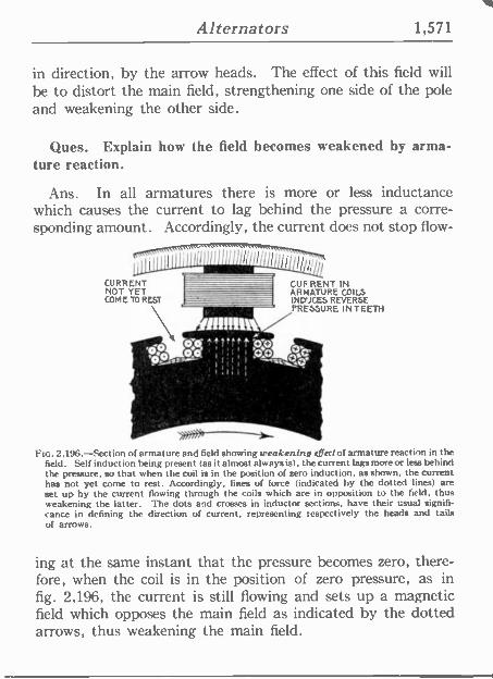
Alternators 1,571
in direction, by the arrow heads. The effect of this field will be to distort the main field, strengthening one side of the pole and weakening the other side.
Ques. Explain how the field becomes weakened by arma- ture reaction.
Ans. In all armatures there is more or less inductance which causes the current to lag behind the pressure a corre- sponding amount. Accordingly, the current does not stop flow -
CURRENT NOT YET COME TO REST
1l
CUF RENT IN ARMATURE COILS INDUCES REVERSE PRESSURE IN TEETH
fii!!!e R -
I I :sÓ iIiI 1.1,.I
no. 2,196.-Section of armature and field showing weakening effect of armature reaction in the field. Self induction being present (as it almost always is), the current lags more or less behind the pressure, so that when the coil is in the position of zero induction, as shown, the current has not yet come to rest. Accordingly, lines of force (indicated by the dotted lines) are set up by the current flowing through the coils which are in opposition to the field, thus weakening the latter. The dots and crosses in inductor sections, have their usual signifi- cance in defining the direction of current, representing respectively the heads and tails of arrows.
ing at the same instant that the pressure becomes zero, there- fore, when the coil is in the position of zero pressure, as in fig. 2,196, the current is still flowing and sets up a magnetic field which opposes the main field as indicated by the dotted arrows, thus weakening the main field.
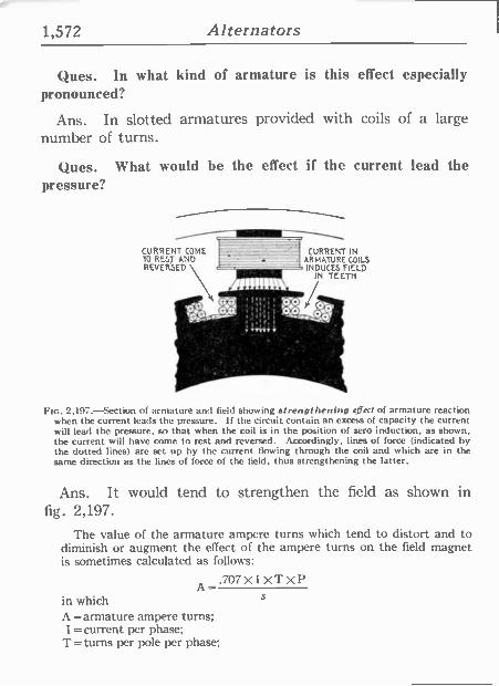
1,572 Alternators
Ques. In what kind of armature is this effect especially pronounced?
Ans. In slotted armatures provided with coils of a large number of turns.
Ques. What would he the effect if the current lead the pressure?
CURRENT COME CURRENT IN TO REST AND ARMATURE COILS REVERSED \ INDUCES FIELD
IN TEETH
FIG. 2,197.-Section of armature and field showing strengthening effect of armature reaction when the current leads the pressure. If the circuit contain an excess of capacity the current will lead the pressure, so that when the coil is in the position of zero induction, as shown, the current will have come to rest and reversed. Accordingly, lines of force (indicated by the dotted lines) are set up by the current flowing through the coil and which are in the same direction as the lines of force of the field, thus strengthening the latter.
Ans. It would tend to strengthen the field as shown in fig. 2,197.
The value of the armature ampere turns which tend to distort and to diminish or augment the effect of the ampere turns on the field magnet is sometimes calculated as follows:
A_.707XIXTXP in which $
A=armature ampere turns; I =current per phase;
T=turns per pole per phase;
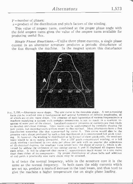
Alternators 1,573
P = number of phases; s=product of the distribution and pitch factors of the winding.
This value of ampere turns, combined at the proper phase angle with the field ampere turns gives the value of the ampere turns available for producing useful flux.
Single Phase Reactions.-Unlike three phase currents, a single phase current in an alternator armature produces a periodic disturbance of the flux through the machine. In the magnet system this disturbance
o=1
225°
2,198.-Alternator wave shape. The sine curve is the desirable shape. A non -sinusoidal form can be resolved into a fundamental and several harmonics of definite amplitudes, all of which are of sine wave shape. The presence of such harmonics of various frequencies in a machine supplying a system with complex connections is apt to result in a resonant re- sponse of some part of the circuit. Localized excessive pressures or currents are then likely to develop and cause damage. Since waves can be approximated by carefully shaping the pole pieces, but manufacturers seldom resort to this method. Most alternators have a flux distribution somewhat like that represented by curve A. This curve would also he the pressure wave shape produced by such a Ilux distribution in a concentrated full pitch wind- ing. If, however. the winding be distributed or he formed of short pitch coils, the resultant wave would be m re nearly sinusoidal. For a 135° pitch concentrated winding, or a full pitch winding c istributed in two slots per phase per pole with an angular slot separation of 45 electrical degrees, the resultant wave would have the shape of curve C. which is ob- tained by adding the ordinates of two similar curves A and ft displaced 45 degrees from each other. It will be observed that curve C. approximates much nearer to a sine curve than does either of its components. fly proper distribution of phase belts and selection of coil pitch a practically sine wave shape may be attained.
is of twice the normal frequency, while in the armature core it is the same as the normal frequency. In both cases the eddy currents which are set up, produce a marked increase in the load losses, and thus tend to give the machine a higher temperature rise on single phase loading.
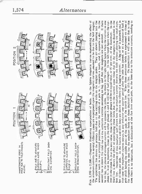
MA
INE
TO
MO
TIV
E
FO
RC
E
IN
FIE
LD
DU
E T
O
FIE
LD
MA
GN
ET
S
ALO
NE
.
FIE
LD D
IJE
T
O
AR
MA
TU
RE
o
CU
RR
EN
TS
A
LON
E
WH
EN
C
OS5
Jt.
RE
SU
LTA
NT
F
IELD
S
HO
W.
INS
D
IST
OR
TIO
N
ó F
IELD
DU
E
TO
AR
MA
TU
RE
°,
C
UR
RE
NT
S
ALO
NE
W
HE
N
t,.>
O
S,' 0
RE
SU
LTA
NT
F
IELD
S
HO
W-
ING
D
EM
AG
NE
TIZ
AT
ION
.
POSI
TIO
N
I
r
POSI
TIO
N
2
Em
s. 2
,199
to
2,2
08.-
Dia
gram
s ill
ustr
atin
g su
perp
ositi
on o
f fi
elds
. In
th
e fi
gure
s m
agne
tic c
urve
s re
pres
entin
g th
e ef
fect
of
the
arm
atur
e cu
rren
ts i
n se
vera
l dif
fere
nt c
ases
are
sup
erpo
sed
upon
the
mag
netic
cur
ves
:ssu
nted
to
be d
ue t
o th
e fi
eld
mag
net.
'fhe
uppe
rmos
t lin
e sh
ows
the
prim
ary
fiel
d du
e to
the
exc
iting
coi
ls
on t
he m
agne
t po
les.
T
hey
are
show
n pa
ssin
g in
to t
he
arm
atur
e te
eth
in
two
prin
cipa
l po
sitio
ns,
whe
re t
he
mid
dle
of a
pol
e is
: 1,
op
posi
te a
too
th,
and
2. o
ppos
ite a
slo
t. In
the
se
cond
lin
e is
sho
wn
the
fiel
d du
e to
the
arm
atur
e cu
rren
ts a
ssum
ing
no l
ag,
and
that
the
mag
nets
are
not
exc
ited.
If
the
re
be n
o la
g, t
he p
lace
s of
str
onge
st c
urre
nt w
ill h
e op
posi
te t
he p
oles
. A
s sh
own
in t
he r
ight
han
d fi
gure
whe
n th
e cu
rren
t in
one
ph
ase
C,
is a
t its
max
imum
, tho
se i
n th
e ot
her
phas
es A
and
B w
ill b
e of
hal
f st
reng
th.
In t
he l
eft
hand
fig
ure
whe
n th
e cu
r-
rent
in o
ne p
hase
B,
is a
t its
zer
o va
lue,
tho
se i
n th
e ot
her
phas
es w
ill h
e of
equ
al v
alue
, or
87
per
cent
. of
the
max
imum
. In
the
th
ird
line
is s
how
n th
e ef
fect
of
supe
rpos
ing
thes
e fi
elds
due
to
the
curr
ent
upon
tho
se d
ue t
o th
e m
agne
ts a
s de
pict
ed i
n th
e fi
rst
line.
In
spec
tion
of t
his
resu
ltant
fie
ld s
how
s ho
w t
he a
rmat
ure
curr
ent
dist
orts
the
fie
ld
with
out
alte
ring
the
tot
al n
um-
ber
of l
ines
per
pol
e.
In t
he f
ourt
h an
d fi
fth
lines
are
sho
wn
the
effe
cts
of a
lag
ging
cur
rent
. A
lag
of
900
is a
ssum
ed;
and
in
that
cas
e th
e m
axim
um c
urre
nt o
ccur
s in
any
in
duct
or o
ne q
uart
er p
erio
d af
ter
the
pole
has
pas
sed,
or
at a
dis
tanc
e of
hal
f a
pole
pitc
h be
hind
the
m
iddl
e po
int
of t
he p
ole,
as
in
the
four
th l
ine.
W
hen
thes
e ar
mat
ure
fiel
ds a
re s
uper
pose
d on
tho
se o
f th
e m
agne
ts i
n th
e fi
rst
line
the
resu
ltant
fie
lds
are
thos
e de
pict
ed i
n th
e fi
fth
line.
O
n in
spec
tion
it w
ill
he s
een
that
in
this
ca
se t
here
is
no
dist
ortio
n, h
ut a
dim
inut
ion
of t
he
flux
fro
m e
ach
pole
, as
the
lin
es d
ue t
o th
e ar
mat
ure
curr
ents
, te
ndin
g to
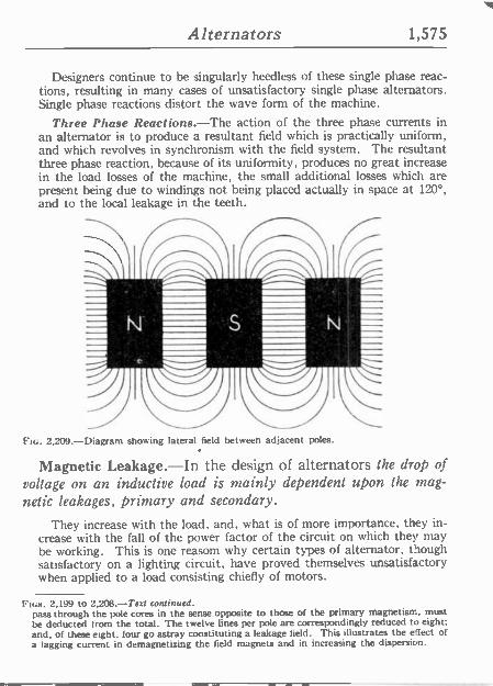
Alternators 1,575
Designers continue to be singularly heedless of these single phase reac- tions, resulting in many cases of unsatisfactory single phase alternators. Single phase reactions distort the wave form of the machine.
Three Phase Reactions.-The action of the three phase currents in an alternator is to produce a resultant field which is practically uniform, and which revolves in synchronism with the field system. The resultant three phase reaction, because of its uniformity, produces no great increase in the load losses of the machine, the small additional losses which are present being due to windings not being placed actually in space at 120°, and to the local leakage in the teeth.
FIG. 2,209.-Diagram showing lateral field between adjacent poles.
Magnetic Leakage.-In the design of alternators the drop of voltage on an inductive load is mainly dependent upon the mag- netic leakages, primary and secondary.
They increase with the load, and, what is of more importance, they in- crease with the fall of the power factor of the circuit on which they may be working. This is one reasom why certain types of alternator, though satisfactory on a lighting circuit, have proved themselves unsatisfactory when applied to a load consisting chiefly of motors.
FIGS. 2.199 to 2.208.-Text continued. pass through the pole cores in the sense opposite to those of the primary magnetism, must be deducted from the total. The twelve lines per pole are correspondingly reduced to eight; and, of these eight, four go astray constituting a leakage field. This illustrates the effect of a lagging current in demagnetizing the field magnets and in increasing the dispersion.
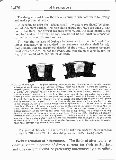
1,576 Alternators
The designer must know the various causes which contribute to leakage and make proper allowance.
In general, to keep the leakage small, the pole cores should be short, and of minimum surface, the pole shoes should not have too wide a span nor be too thick, nor present needless corners, and the axial length of the pole face and of the armature core should not be too great in proportion to the diameter of the working face.
To keep the increase of leakage between no load and full load from undue magnitude. it is required that armature reactions shall be rela- tively small, that the peripheral density of the armature current (ampere - conductors per inch) be not too great, and that the pole cores be not too highly saturated when excited for no load.
I'Ics. 2,210 and 2.211.-Diagram showing respectively the character of stray field between adjacent straight poles, and between adjacent poles with shoes. Across the slightly V- shaped spaces the stray field passes in lines that, save near the outer part. are nearly straight. Quite straight they would not be, even were the sides parallel, because the differ- ence of magnetic pressure increases from the roots toward the pole ends. At the roots. where the cores are attached to the yoke, the magnetic pressure difference is almost zero. It would be exactly zero if there were not a perceptible reluctance offered by the joints and by the metal of the yoke. The reluctance of the joint causes a few of the lines to take paths through the air by a leakage which adds to tike useful flux. At the tops of the core there is a difference of magnetic pressure equal tote sum of the ampere -turns on the two cores, tending to drive magnetic lines across. This difference of magnetic pressure in- creases regularly all the way up the cores from root to top; hence, the average value may be taken as equal to the ampere turns on one core. The stray field, therefore, will steadily increase in density from the bottom upward. In addition to this stray field between the pole cores there is also a stray field between the projecting tips or edges of the pole shoes. as shown in fig. 2,211. In some machines the dispersion due to the pole shoes is greater than that between the flanks of the cores.
The general character of the stray field between adjacent poles is shown in figs. 2,210 and 2,211 for straight poles and those having shoes.
Field Excitation of Alternators.-The fields of alternators re- quire a separate source of direct current for their excitation, and this current should be preferably automatically controlled.
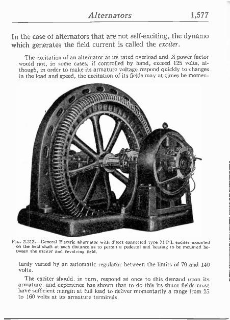
Alternators 1,577
In the case of alternators that are not self -exciting, the dynamo which generates the field current is called the exciter.
The excitation of an alternator at its rated overload and .8 power factor would not, in some cases, if controlled by hand, exceed 125 volts, al- though, in order to make its armature voltage respond quickly to changes in the load and speed, the excitation of its fields may at times be momen-
z41 I®>, f^6
."'.,.. 1!41.
cíJ
FIG. 2.212.-General Electric alternator with direct connected type M P L exciter mounted on the field shaft at such distance as to permit a pedestal and bearing to be mounted be- tween the exciter and revolving field.
tarily varied by an automatic regulator between the limits of 70 and 140 volts.
The exciter should, in turn, respond at once to this demand upon its armature, and experience has shown that to do this its shunt fields must have sufficient margin at full load to deliver momentarily a range from 25 to 160 volts at its armature terminals.
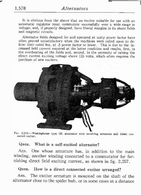
1,578 Alternators
It is obvious from the above that an exciter suitable for use with an automatic regulator must commutate successfully over a wide range in voltage, and, if properly designed, have liberal margins in its shunt fields and magnetic circuits.
Alternator fields designed for and operated at unity power factor have often proved unsatisfactory when the machines were called upon to de- liver their rated kva. at .8 power factor or lower. This is due to the in- creased field current required at the latter condition and results, first, in the overheating of the fields and, second, in the necessity of raising the direct current exciting voltage above 125 volts, which often requires the purchase of new exciters.
f.
. .e
no. 2,213.-Westinghouse type SK alternator with revolving armature and direct con- nected exciter.
Ques. What is a self-excited alternator? Ans. One whose armature has, in addition to the main
winding, another winding connected to a commutator for fur- nishing direct field exciting current, as shown in fig. 2,257.
Ques. How is a direct connected exciter arranged? Ans. The exciter armature is mounted on the shaft of the
alternator close to the spider hub, or in some cases at a distance
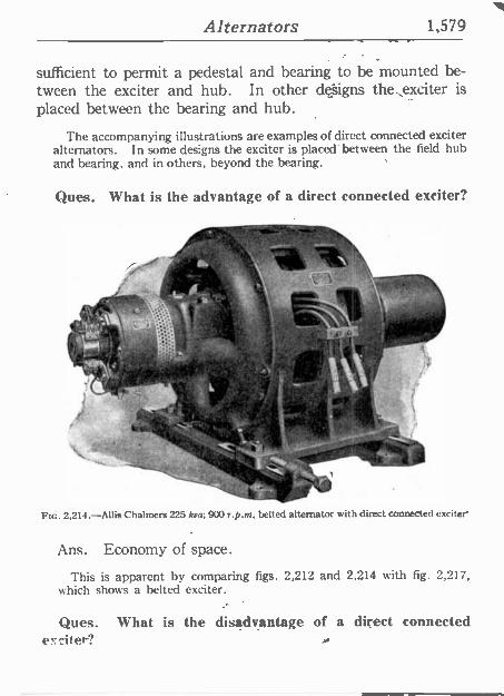
Alternators 1,579
sufficient to permit a pedestal and bearing to be mounted be- tween the exciter and hub. In other designs the,exciter is placed between the bearing and hub.
The accompanying illustrations are examples of direct connected exciter alternators. In some designs the exciter is placed' between the field hub and bearing, and in others, beyond the bearing.
Ques. What is the advantage of a direct connected exciter?
." Ni...
le
¿n%
tr
.4"§ , ' ti 1
i
F[c. 2,214.-Allis Chalmers 225 kva; 900 r.p.at. belted alternator with direct connected exciter
Ans. Economy of space.
This is apparent by comparing figs. 2,212 and 2,214 with fig. 2,217, which shows a belted exciter.
Ques. What is the disadvantage of a direct connected e'; ci l er?
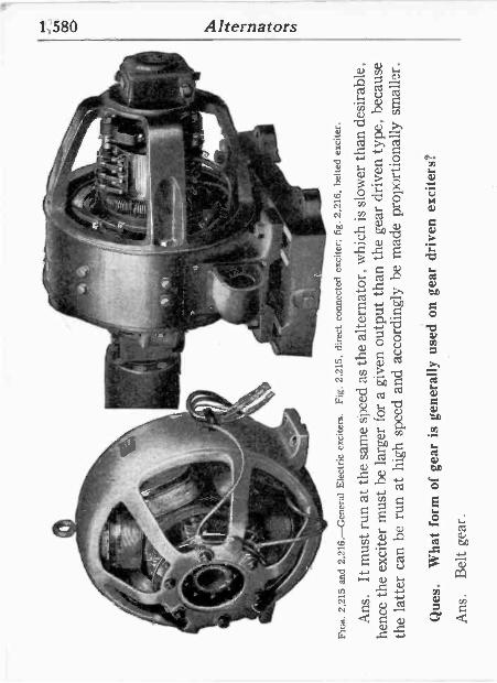
Iif
r, i
. ...
.
', .
.
}
--.
u .
C.!
,!s
7,
'r a
r .
l uIn
.
o
Fin
s. 2
,215
and
2.2
16. -
-Gen
eral
Ele
ctric
exc
iters
. F
ig.
2.21
5,
dire
ct c
onne
cted
exc
iter;
fig
. 2,
216,
bel
ted
exci
ter.
Ans
. It
mus
t run
at
the
sam
e sj
)eed
as
the
alte
rnat
or,
whi
ch is
slo
wer
than
des
irab
le,
henc
e th
e ex
cite
r m
ust
be l
arge
r fo
r a
give
n ou
tput
tha
n th
e ge
ar d
rive
n ty
pe,
beca
use
the
latte
r ca
n be
run
at
high
spe
ed a
nd a
ccor
ding
ly b
e m
ade
prop
ortio
nally
sm
alle
r.
Que
s.
Wha
t fo
rm o
f ge
ar i
s ge
nera
lly u
sed
on g
ear
driv
en e
xcite
rs?
Ans
. B
elt
gear
.
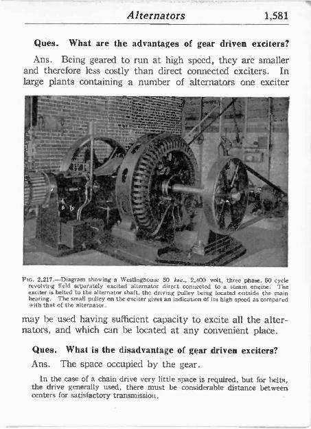
Alternators 1,581
Ques. What are the advantages of gear driven exciters?
Ans. Being geared to run at high speed, they are smaller and therefore less costly than direct connected exciters. In large plants containing a number of alternators one exciter
.1. i - " 1-..'41..
- wurw,. w...:.¡,Á ¡ !x#'
á .. r =..r.: Á, q . - - ;11/ t;
_ 4 i/ , I
' lWreec.~ ,' I
i; FY -
moo 1, a__yrd'l1 ,
Ftc. 2,217.-Diagram showing a Westinghouse 50 kva., 2,400 volt, three phase, 60 cycle revolving field separately excited áltemator direct connected to a steam engine. The exciter is belted to the alternator shaft, the driving pulley being located outside the main hearing. The small pulley on the exciter gives an indication of its high speed as compared with that of the alternator.
may be used having sufficient capacity to excite all the alter- nators, and which can be located at any convenient place.
Ques. What is the disadvantage of gear driven exciters? Ans. The space occupied by the gear.
In the case of a chain drive very little space is required, but for belts, the drive generally used, there must be considerable distance between centers for satisfactory transmission.
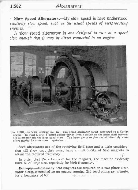
1;582 Alternators
Slow. Speed Alternators.-By slow speed is here understood relatively slow speed, such as the usual speeds of reciprocating engines. '
A slow speed alternator is one designed to run at a speed slow enough that it may be direct connected to an engine.
75
, r, o
ltif f
f
1;,
"é".. r , irs
.e ''
r
FIG. 2.218:-Crocker-Wheeler 350 kva., slow speed alternator direct connected to a Corliss engine. In front is seen a belted exciter driven from a pulley on the main shaft between the alternator and the large band wheel. The latter serves to give tlx additional fly wheel effect needed for close speed regulation.
Such alternators are of the revolving field type and a little considera- tion will show that they must have a multiplicity of field magnets to attain the required frequency.
In order that there be room fór the magnets, the machine evidently must be of large size, especially for high frequency.
.Example;=How.many field magnets, -are required on a two phase alter- nator diregt,eonnected ,to an engine running 240 revolutions per minute, for a frequency of 60?
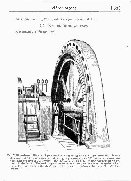
Alternators 1,583
An engine running 240 revolutions per minute will turn
240=60 =4 revolutions prr second.
A frequency of 60 requires
FIG. 2,219.-General Electric 48 pole 750 k, a., three phase fly wheel type alternator. It runs at a speed of 150/revolutions per minute, giving a frequency of 60 cycles per second and a full load pressure of 2,300 volts. The slip rings and leads to the field winding are clearly shown in the figure. The field magnets are mounted directly on the rim of the spider, which resembles very closely a fly wheel, and which in fact it is-hence the name "fly wheel al- ternator."
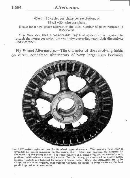
1,584 Alternators
60+4 =15 cycles per phase per revolution, or 15X2=30 poles per phase.
I lence for a two phase alternator the total number of poles required is 30 X2 = 60.
It is thus seen that a considerable length of spider rim is required to attach the numerous poles, the exact size depending upon their dimensions and clearance.
Fly Wheel Alternators.-The diameter of the revolving fields on direct connected alternators of very large sizes becomes
. 3 s
.
o .
- , r . ,
.
..^'-3...__ -- '- e
2,220.-Westinghouse rotor for fly wheel type alternator. The revolving field rotor is arranged for direct mounting on the engine shaft. Shaft and bearings are supplied by the maker of the prime mover. The rotor consists of a single steel casting carefully pro- portioned with reference to cooling strains. To this casting, punched steel laminated poles. securely riveted, are fastened by means of heavy bolts. When the alternators are to be driven by gas or oil engines, cage damper windings are added in order to secure the best parallel operation between units.
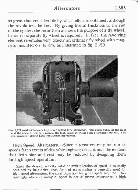
Alternators 1,585
so great that considerable fly wheel effect is obtained, although the revolutions be low. By giving liberal thickness to the rim of the spider, the rotor then answers the purpose of a fly wheel, hence no separate fly wheel is required. In fact, the revolving element resembles very closely an ordinary fly wheel with mag- nets mounted on its rim, as illustrated in fig. 2,219.
_J'
1 tc. 2,221.-Allis-Chalmers high speed belted type alternator. The small pulley at the right and the angle of the belt suggest the high speed at which such alternators are run, a 50 kva. machine turning 1,200 revolutions per minute.
High Speed Alternators.-Since alternators may be run at speeds far in excess of desirable engine speeds, it must be evident that both size and cost may be reduced by designing them for high speed operation.
Since the desired velocity ratio or multiplication of speed is so easily obtained by belt drive, that form of transmission is generally used for high speed alternators, the chief objection being the space required. Ac- cordingly where economy of space is not of prime importance, a high
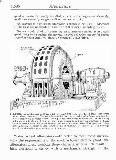
1,586 Alternators
speed alternator is usually installed, except in the large sizes where the conditions naturally suggest a direct connected unit.
An example of high speed alternator is shown in fig. 2,221. Machines of this class run at speeds of 1,200 to 1,800 or more, according to size.
No one would think of connecting an alternator running at any such speed direct to an engine, the necessary speed reduction proper for engine operation being easily obtained by means of a belt drive.
HOLES FOR VENTILATION
FLANGE FOR CONNECTION TO WATER WHEEL
gio feel l///I/gPol/,L
IIII II'il11IIInÍ{lii¡¡I llu unulllm Iluu nntyllllllllll IIIIIIIII Inulnlllllluu,
'IIIi4l!I¡,Illn¡tItUnluultlulllllll'IIIIIIII.! Illlllp,
IIII!I
SHIELD
mitllllllÍli(Illlill
PIG. 2,222.-Allis-Chalmers 5.000 kra., 450 r. p. m., 6,600 volt, 60 cycle, 3 phase, horizontal water wheel alternator. The shaft is extended for the reception of a flange coupling for direct connection to water wheel. Owing to the wide range in output of the generating units and also in the speed at which they must operate to suit varying conditions of head. types of wheels user, and other features pertaining to water power developments, it has been necessary to design a very complete line of machines for this work. The bearings are of the ring oiling type with large oil reservoirs.
Water Wheel Alternators.-In order to meet most success- fully the requirements of the modern hydro -electric plant, the alternators must combine those characteristics which result in high electrical efficiency with a mechanical ,strength of the
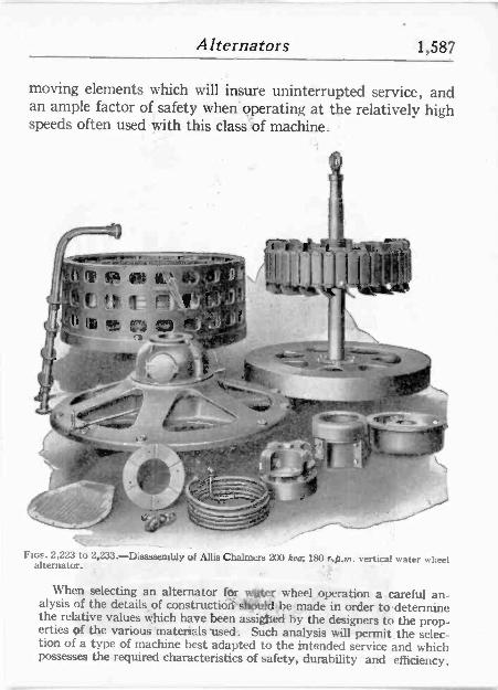
Alternators 1,587
moving elements which will insure uninterrupted service, and an ample factor of safety when operating at the relatively high speeds often used with this class 'of machine.
` .
l_^' ' '----'1'-' Y =b,y M
'ix Z iá91,
,4t® r 11°
r °llti "dr _ -0 , 197,
i
r `! 1?
-p - n'
^ ..
Fins. 2,223 to 2,233: D; i embly of Allis Chalmers 200 kna, 180 r,p.m. vertical water wheel alternator.
When selecting an alternator for Later wheel,operation a.careful an- alysis of the details of constructióit slípuld be;made in order todetermine the relative values which have been assigned by the designers to the prop- erties of .the various' materials used-. Such analysis will permit the selec- tion of a type of machine best adapted to the intended service and which possesses thé required characteristics of safety, durability and efficiency.
S
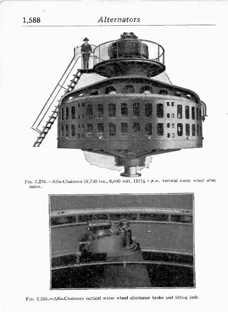
1,588 Alternators .
1 _-p
' 1 Í 9
I
1 "
LIZ
-110,Fo- 1,4
o
. 1 111
Y- GUY O >.
1:0
as .
Ftc. 2,234.-Allis-Chalmers 18,750 koa., 6,600 volt, 11214 r.p.m. vertical water wheel alter. nator.
n - . Í ~l --s ,-'-_ ` t
.. . , i ^.4 ly jt y
, P
+t:
..--- . ¡F'I ^ w
C
Ftc. 2,235.-Allis-Chalmers vertical water wheel alternator brake and lifting jack.
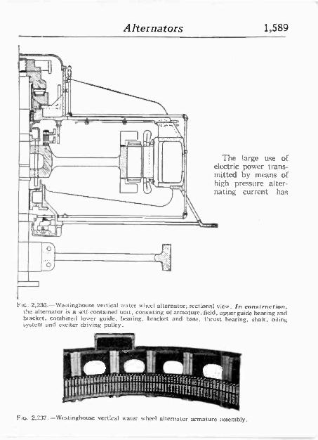
Alternators 1,589
The large use of electric power trans- mitted by means of high pressure alter- nating current has
Ftc. 2,236.-Westinghouse vertical water wheel alternator; sectional view. In coma ruction. the alternator is a sell contained unit, consisting of armature, field, upper guide hearing and bracket, combined lower guide, bearing, bracket and base, thrust bearing, shalt, oiling system and exciter driving pulley.
111111,
!ill ji ii, !!!1'!ilstig 9l t ' A144'
FIG,. 2,237. --Westinghouse vertical water wheel alternator armature assembly.
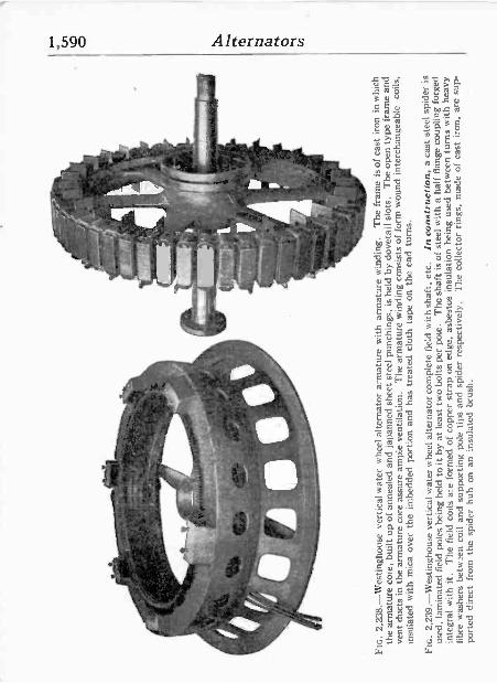
kiD
o t"
--.,
_---
-; ..
.
;- ó
°á
:s
.°,
=_
l¡ _
,rn'
' t
1 f
., , . .
--
-C
f, ,
_ ~
; ,_
q-.,,
. +
- J
; i.`
{*
N
t t '
1'°
t.,`
I.
Q"r
-`_
1i
``-
`" r
'
` ,iD
SI
\1
----
--
a Ó
`
.1
` -
- ..z
.-:..
...._
:.1
1.
.r .
rte+
,
FIG
. 2,
238.
-Wes
tingh
ouse
ver
tical
wat
er w
heel
alte
rnat
or a
rmat
ure
with
ar
mat
ure
win
ding
. T
he f
ram
e is
of
cast
iron
in
whi
ch
the
arm
atur
e co
re,
built
up
of a
nnea
led
and
japa
nned
she
et s
teel
pun
chin
gs,
is h
eld
by d
ovet
ail
slot
s.
The
ope
n ty
pe f
ram
e an
d ve
nt d
ucts
in
the
arm
atur
e co
re a
ssur
e am
ple
vent
ilatio
n.
The
arm
atur
e w
indi
ng c
onsi
sts
of f
orm
wou
nd
inte
rcha
ngea
ble
coils
, in
sula
ted
with
mic
a ov
er t
he
imbe
dded
por
tion
and
has
trea
ted
clot
h ta
pe o
n th
e en
d tu
rns.
FIG
. 2.
239.
-Wes
tingh
ouse
ver
tical
wat
er w
heel
alte
rnat
or c
ompl
ete
fiel
d w
ith s
haft
, et
c.
In c
onst
ruct
ion,
a c
ast
stee
l sp
ider
is
used
, la
min
ated
fie
ld p
oles
bei
ng h
eld
to i
t by
at l
east
tw
o bo
lts p
er p
ole.
T
he sh
aft
is o
f st
eel
with
a h
alf
flan
ge c
oupl
ing
forg
ed
inte
gral
w
ith i
t. T
he f
ield
coi
ls a
re f
orm
ed o
f co
pper
str
ap o
n ed
ge,
asbe
stos
ins
ulat
ion
bein
g us
ed b
etw
een
turn
s w
ith h
eavy
fi
bre
was
hers
bet
wee
n co
il an
d su
ppor
ting
pole
tip
s an
d sp
ider
res
pect
ivel
y.
The
col
lect
or r
ings
, m
ade
of c
ast
iron
, ar
e su
p-
port
ed d
irec
t fr
om t
he s
pide
r hu
b on
an
in
sula
ted
brus
h.
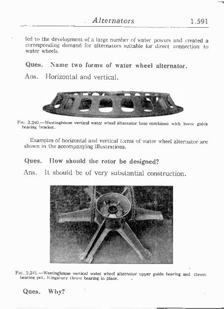
. Alternators 1.591
led to the development of a large number of water powers and created a corresponding demand for alternators suitable for direct connection to water wheels.
Ques. Name two forms of water wheel alternator.
Ans. Horizontal and vertical.
- {tL]V'LJ-S, !v._+y.,JFCs P
` r ' (tad ,. o I
FIG. 2.240.-Westinghouse vertical water wheel alternator base combined with loner guide bearing bracket.
Examples of horizontal and vertical forms of water wheel alternator are shown in the accompanying illustrations.
Ques. Ilow should the rotor he designed?
Ans. It should be of very substantial construction.
f , ' , FIG. 2,241 -Westinghouse vertical water wheel alternator upper guide bearing and thrust
bearing pot. Kingsbury thrust bearing in place.
Ques. Why?
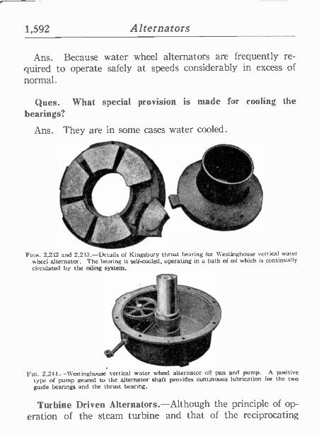
1,592 Alternators
Ans. Because water wheel alternators are frequently re- quired to operate safely at speeds considerably in excess of normal.
Ques. What special provision is made for cooling the bearings?
Ans. They are in some cases water cooled.
Fins. 2,212 and 2,243.-Details of Kingsbury thrust bearing for Westinghouse vertical water wheel alternator. The bearing is self -cooled, operating in a bath of oil which is continually circulated by the oiling system.
f ---i. .
.uV y ir
..
. .
Fin. 2,244.-Westinghouse vertical water wheel alternator oil pan and pump. A positive type of pump geared to the alternator shaft provides continuous lubrication for the two guide bearings and the thrust bearing.
Turbine Driven Alternators.-Although the principle of op- eration of the steam turbine and that of the reciprocating
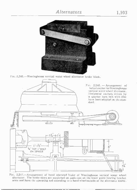
FIc. 2.246. - Arrangement of belted exciter forWestinghouse vertical water wheel alternator. Horizontal exciters driven by a quarter turn belt with idler have been adopted as the stan- dard.
Alternators 1,593
FIG. 2,245.-Westinghouse vertical water wheel alternator brake block.
2 213"
'k" TOP I' DEEP ON SPIDER'
-
FIG. 2,247.-Arrangement of hand oderated brake of Westinghouse vertical water wheel alternator. The brake shoes are supported on pads cast on the lower guide bearing bracket arms and have the operating rod extending to a hand wheel outside of the alternator frame.
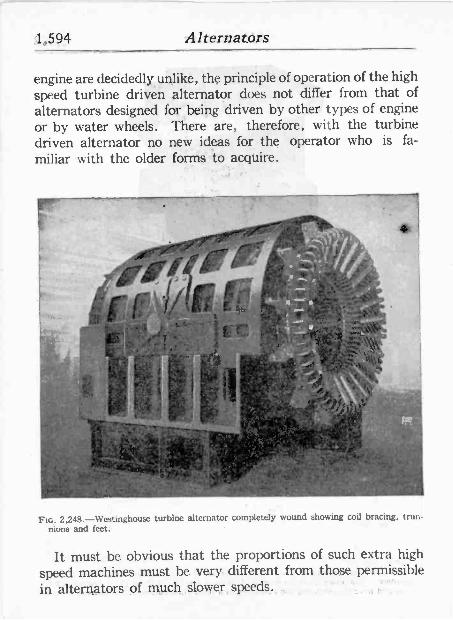
;1,594 Alternazórs
engine are decidedly uñlike, the principle of operation of the high speed turbine driven alternator does not differ from that of alternators designed for" being driven by other types of engine or by water wheels. There are, therefore, with the turbine driven alternator no new .ideas for the operator who is fa- miliar with the older forms to acquire.
ir, _,,;111
.., { " i. ° ! 0
,:
tl., b .11,......'..,
'"..- _.
>-'
1 / liL.ip k 'r.:' g .i,. . =1 ' " .4 ,, ; , ; ...4.;_ '. .,o .. ' g;,- .. . ^ y4.., o
- '`,-`
\1.\' .
4
r'. . _` t I 't E:1{yx ti .á +t.k}; , A. 't, ` 7^.a
r,:r_ . +
+ '{ '', trap x :.:11
i.h r. p o !I. t+'.
:lf`yi i '4 . l .,-;4.-..
'} ' - 1
.
;.vl' . ' 4
` ' '
{ '
.
r ;f/ .. . e: aI% . r o!i' . ..
`111,,,,:°.°'7";' <' r e`:I
- a.: i" ;:,,M:, 43.... _
:Y . J .
1":,1 i } arM.ry.
w - 7 11.11v `9
42:4' },g.
FIG. 2,248.-Westinghouse turbine alternator completely wound showing coil bracing, trun- nions and feet. -
It must be obvious that the proportions of such extra high speed machines must be very different from those permissible in alternators of much slower, speed's.
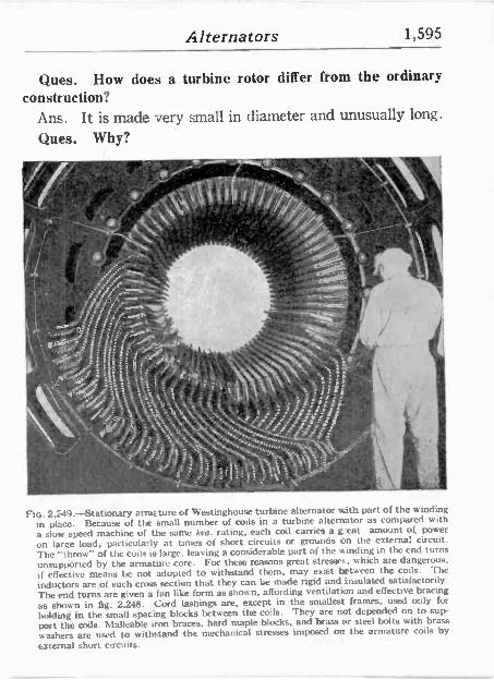
Alternators 1,595
Ques. How does a turbine rotor, differ from the ordinary construction?
Ans. It is made very small in diameter and unusually long.
Ques. Why?
e :,-... . '' ót. S
vy \'_` b,:
:,.1' 65)º _ .
r /f: : 'r .re..
j. "..:7"..~.'
i //amt. ` ji= ti(j! tG
o,;r."';;:,f ... F, ,C)
.`_,,.'i:' i * . ~.. L 9 /^ , '..W,:'c \ ̀ ':: 'u ' .3C _ -, r,u-r
S,a. í ; =*ss r `\`t.%;"... g '='o':!' . :
s" ; 0 3`- s j -i:: i- .
4
44Siyy. ; .' ` i .'{i i : q '' S ,T'yOf f% S'f` S ¡ . - ',_ .: .; ,', .:;;"`:::`áVw.......,;.
- -' Qil. .. 4,N I t y
:'s fo/ rj j y t. Sry/ r ia.. tI _^^o Fin. 2, 49.-Stationary armature of Westinghouse turbine alternator with part of the winding
in place. Because of the small number of coils in a turbine alternator as compared with
a slow speed machine of the same kra. rating, each coil carries a eat amount of power
on large load, particularly at times of short circuits or grounds on the external circuit. The "throw" of the coils is large. leaving a considerable part of the winding in the end turns unsupported by the armature core. For these reasons great stresses, which are dangerous, if effective means he not adopted to withstand them, may exist between the coils. The
inductors are of such cross section that they can be made rigid and insulated satisfactorily. The end turns are given a fan like form as shown, affording ventilation and effective bracing
as shown in fig. 2,248. Cord lashings are, except in the smallest frames, used only for
holding in the small spacing blocks between the coils. They are not depended on to sup-
port the coils. Malleable iron braces, hard maple blocks, and brass or steel bolts with brass washers are used to withstand the mechanical stresses imposed on the armature coils by
external short circuits.
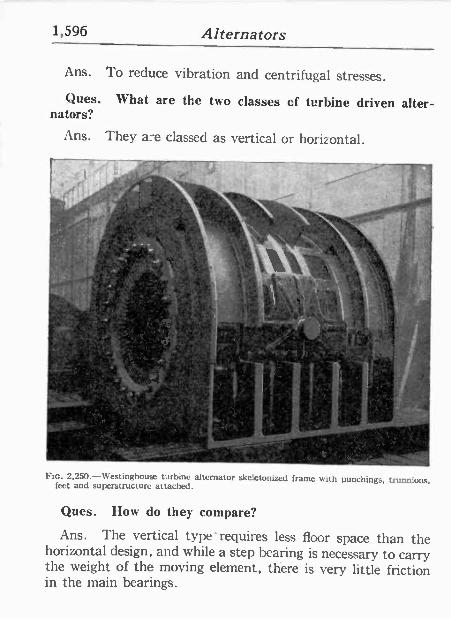
1,596 Alternators
Ans. To reduce vibration and centrifugal stresses.
Ques. What are the two classes cf turbine driven alter- nators?
Ans. They a:e classed as vertical or horizontal.
-
.--
o ' t \ . ~\ 4`Z1
, 'N .. ry'; ` ̀ , `
l . w.
.
Í`
.
. .
. FIG. 2,250.-Westinghouse turbine alternator skeletonized frame with punchings, trunnions, feet and superstructure attached.
Ques. How do they compare?
Ans. The vertical type' requires less floor space than the horizontal design, and while a step bearing is necessary to carry the weight of the moving element, there is very little friction in the main bearings.
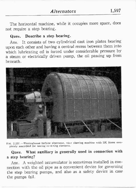
Alternators 1,597
The horizontal machine, while it occupies more space, does not require a step bearing.
Ques. Describe a step bearing.
Ans. It consists of two cylindrical cast iron plates bearing upon each other and having a central recess between them into which lubricating oil is forced under considerable pressure by a steam or electrically driven pump, the oil passing up from beneath.
1111~
,é
t
1 -Iv..
_,
,,` FIG. 2,251 -Westinghouse turbine alternator, view showing machine with SK frame com-
pletely assembled for testing revolving elements.
Ques. What auxiliary is generally used in connection with
a step bearing? Ans. A weighted accumulator is sometimes installed in con-
nection with the oil pipe as a convenient device for governing the step bearing pumps, and also as a safety device in case the pumps fail.
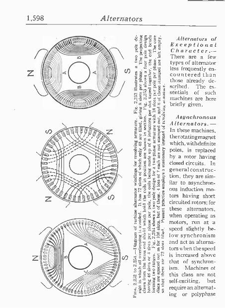
1,598 Alternators
.1.1.11g¿, :flternators of w19216 Exceptional $ó a,eH Character.- o
a $ v There are a few types of alternator
i0 ° ra less frequently en - N q cs countered than ° ís 3 ú a o d those already de-
scribed. The es- , 5 á á seirtials of such 0004.c: ;.c, s = machines are here
mti ó y co x briefly given. 00 Yry upp9 11j 6 l
íu..
a 3 0 L
= ti 7 5 °-'o ? ci
Da O C a0 E N N c G R 0 O
> Q TNac d°1
ro ct ó Ó u A 3 r E w
O
12.-8;11 m v. 579,:11141 u u
CL.rC ph . ái o °
ó'gt 51 o y6 _>a-ryó O m G,lSOt
i= FmL ct[lNó C w
GtiaGi°`s"N. Ó+° N .
C 9,- a A Ó na O
íu. i°uNML'ro N C u
u Ñ C 4 tE,oN c"mcrom
. >E- m . $- V m u.C.- 9
Asynchronous Alternators. - In these machines, therotatingmagnet which, withdefinite poles, is replaced by a rotor having closed circuits. In general construc- tion, they are sim- ilar to asynchron- ous induction mo- tors having short circuited rotors; for these alternators, when operating as motors, run at a speed slightly be- low synchronism and act as alterna- tors when the speed is increased above that of synchron- ism. Machines of this class are not self -exciting, but require an alternat- ing or polyphase
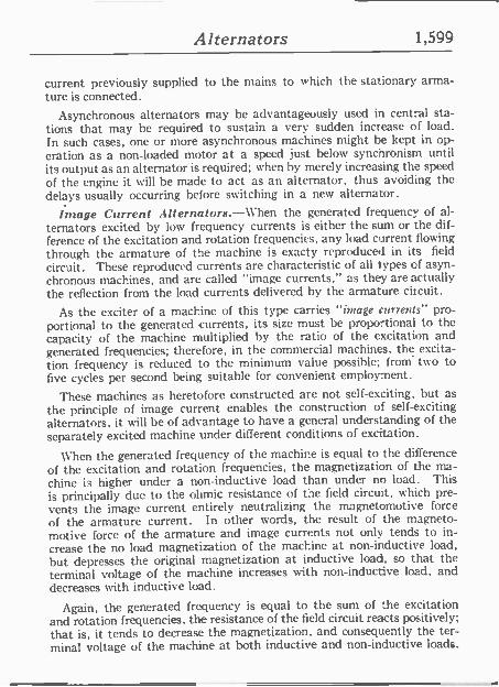
Alternators 1,599
current previously supplied to the mains to which the stationary arma- ture is connected.
Asynchronous alternators may be advantageously used in central sta- tions that may be required to sustain a very sudden increase of load. In such cases, one or more asynchronous machines might be kept in op- eration as a non -loaded motor at a speed just below synchronism until its output as an alternator is required; when by merely increasing the speed of the engine it. will be made to act as an alternator, thus avoiding the delays usually occurring before switching ín a new alternator.
Image Current Alternators.-When the generated frequency of al- ternators excited by low frequency currents is either the sum or the dif- ference of the excitation and rotation frequencies, any load current flowing through the armature of the machine is exacty reproduced in its field
circuit. These reproduced currents are characteristic of all types of asyn- chronous machines, and arc called "image currents," as they are actually the reflection from the load currents delivered by the armature citcuit.
As the exciter of a machine of this type carries "image currents" pro- portional to the generated currents, its size must be proportional to the capacity of the machine multiplied by the ratio of the excitation and generated frequencies; therefore, in the commercial machines, the excita- tion frequency is reduced to the minimum value possible; from' two to five cycles per second being suitable for convenient employment.
These machines as heretofore constructed are not self -exciting, but as
the principle of image current enables the construction of self -exciting alternators, it will be of advantage to have a general understanding of the separately excited machine under different conditions of excitation.
When the generated frequency of the machine is equal to the difference of the excitation and rotation frequencies, the magnetization of the ma- chine is higher under a non -inductive load than under no load. This is principally due to the ohmic resistance of the field circuit, which pre- vents the image current entirely neutralizing the magnetomotive force of the armature current. In other words, the result of the magneto - motive force of the armature and image currents not only tends to in-
crease the no load magnetization of the machine at non -inductive load, but depresses the original magnetization at inductive load, so that the terminal voltage of the machine increases with non -inductive load, and decreases with inductive load.
Again, the generated frequency is equal to the sum of the excitation and rotation frequencies, the resistance of the field circuit reacts positively; that is, it tends to decrease the magnetization, and consequently the ter- minal voltage of the machine at both inductive and non -inductive loads.
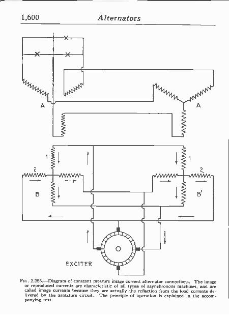
1,600 Alternators
Bt
Ftc. 2,255 -Diagram of constant pressure image current alternator connections. The image or reproduced currents are characteristic of all types of asynchronous machines, and are called image currents because they arc actually the reflection from the load currents de- livered by the armature circuit. The principle of operation is explained in the accom- panying text.
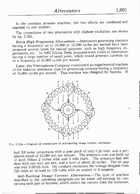
Alternators 1,601
In the constant pressure machine, the two effects are combined and opposed to one another.
The connections of two alternators with diphase excitation are shown
by fig. 2,255.
Extra high Frequency .4iternafors.-Alternators generating currents having a frequency up to 10,000 or 15,000 cycles per second have been
proposed several times for special purposes, such as high frequency ex-
periments, etc. In 1902 Nil:ola Tesla proposed.some forms of alternators having a large number of small poles, which would generate currents up to a frequency of 15,000 cycles per second.
Later, the Westinghouse Company constructed an experimental machine of the inductor alternator type for generating currents having a frequency
of 10,000 cycles per second. This machine was designed by Samms. It
2,256.-Diagram of connections of self -exciting image current alternator.
had 200 polar projections with a pole pitch of only 0.25 inch, and a per-
ipheral speed of 25.000 feet per minute. The armature core was built up
of steel ribbon 2 inches wide and 3 mils thick. The armature had 400
slots with one wire per slot, and a bore of about 25 inches. The air gap
was only 0.03125 inch. On constant excitation the voltage dropped from
150 volts at no-load to 123 volts with an output of 8 amperes.
Self -Exciting Image Current Alternators.-The type of machine
described in the preceding paragraph can he made self -exciting by con-
necting each pair of brushes, which collect the current from the armature,

1,602 Alternators
with a field coil so located that the flux it produces will be displaced by a pre -determined angle depending on the number of phases required, as shown by fig. 2,256. The direction of the residual magnetism of the machine is shown by the arrows A, A.
When the armature is rotated, a pressure will be generated between the brushes 2 and 4, and a current will flow from C, through the coils XX, to B, producing a flux through the armature at right angles to the residual magnetism and establishing a resultant magnetic field between I), B, and D, C. This field will generate a pressure between the brushes 1 and 3, and a current will flow D, through XX, to E, in such a direction that it will at first be opposed to the residual magnetism, and afterward reverse the direction of the latter. At the moment the residual magnet- ism becomes zero, the only magnetism left in the machine will be due to the currents from the brushes 2 and 4, and their field combining with the vertical reversed field will produce a resultant polar line between B and E. As these operations are cyclic, they will recur at periodic inter- vals, and the phenomena will become continuous. The negative field thus set up in the air gap of the machine will cut the conductors of the stator and will be cut by the conductors of the rotor in such a manner that the voltages generated between the brushes of the armature will be equal and opposite to those between the terminals of the stator.
TEST QUESTIONS
1. For what service are alternators adapted? 2. Give a classification of alternators. 3. \V71at are the essential features of a single phase
alternator? 4. In actual machines, why must the magnet cores be
spaced out around the armature with considerable distance between them?
5. Is there any gain in making the width of the arma- ture coils any greater than the pole pitch, and why?
6. Define a polyphase alternator and what is its use? 7. What is the difficulty encountered in starting a motor
with single phase current?
Alternators 1,603
8. In what type machine are six phase and twelve phase windings used?
9. Upon what does the choice of belt driven or direct connected alternators depend?
10. What provision should be made in the design of an alternator to adapt it to belt drive?
11. Give a rule for obtaining the proper size of belt to deliver a given horse power.
12. What are some of the objections to chain drive? 13. What is the difference between a direct connected
and a direct coupled unit? 14. When is the revolving type of armature used, and
why? 15. Could a dynamo be converted into an alternator? 16. What is the nature of motion? 17. What are the advantages of revolving field alter-
nators? 18. Explain the essential features of a revolving field
alternator. 19. \'(hat is an inductor alternator? 20. What influence have the inductors on the field flux? 21. Name two classes of inductor alternators. 22. State a disadvantage of inductor alternators. 23. For what service are inductor alternators adapted? 24. Define the term hunting or singing in alternators. 25. What is a monocyclic alternator? 26. What is an amortisseur winding used for? 27. What is a teaser coil? 28. Define armature reaction.
1,604 Alternators
29. Explain how the field becomes distorted by armature reaction.
30. Explain how the field becomes weakened by armature react ion .
31. In what kind of armature is the weakening by arma- ture reaction especially pronounced?
32. What would be the effect if the current lead the pres- sure?
33. Describe single phase, and three phase reaction. 34. Draw diagrams illustrating super -position of fields. 35. Define magnetic leakage and what causes it. 36. In what ways are the fields of alternators excited? 37. What is a self-excited alternator? 38. What are the advantages of gear driven exciters? 39. How is a fly wheel alternator constructed? 40. What are the features of water wheel alternators? 41. Ilow does a turbine armature differ from the ordin-
ary construction, and why? 42. Name two classes of turbine alternators. 43. Describe a step bearing. 44. Describe some alternators of exceptional character.
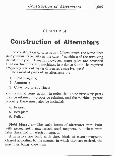
Construction of Alternators 1,605
CIIAPTCIZ 51
Construction of Alternators The construction of alternators follows much the same lines
as dynamos, especially in the case of machines of the revolving armature type. Usually, however, more poles are provided than on direct current machines, in order to obtain the required frequency without being driven at excessive speed.
The essential parts of an alternator are:
1. Field magnets; 2. Armature; 3. Collector, or slip rings;
and in actual construction, in order that these necessary parts may be retained in proper co -relation, and the machine operate properly there must also be included:
4. Frame; 5. Bed plate; 6. Pulley.
Field Magnets.-The early forms of alternator were built with permanently magnetized steel magnets, but these were later discarded for electro -magnets.
Alternators are built with three kinds of electro -magnets, classed according to the manner in which they are excited, the machines being known as:
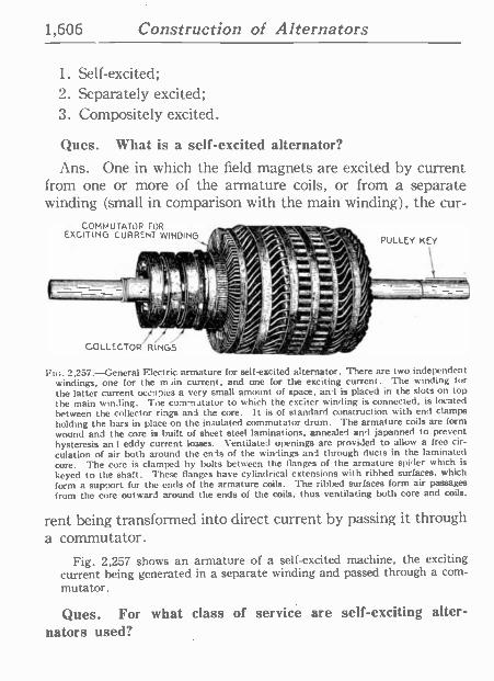
1,606 Construction of Alternators
1. Self-excited; 2. Separately excited; 3. Compositely excited.
Ques. What is a self-excited alternator?
Ans. One in which the field magnets are excited by current from one or more of the armature coils, or from a separate winding (small in comparison with the main winding), the cur -
COMMUTATOR FOR EXCITING CURRENT WINOING
COLLECTOR RINGS
Fig. 2,257.-General Electric armature for self-excited alternator. There are two independent windings, one for the main current, and one for the exciting current. The winding for the latter current occn7ies a very small amount of space, and is placed in the slots on top the main winding. Toe commutator to which the exciter winding is connected, is located between the collector rings and the core. It is of standard construction with end clamps holding the bars in place on the insulated commutator drum. The armature coils are form wound and the core is built of sheet steel laminations, annealed and japanned to prevent hysteresis and eddy current losses. Ventilated openings are provided to allow a free cir- culation of air both around the ends of the windings and through ducts in the laminated core. The core is clamped by bolts between the flanges of the armature spider which is keyed to the shaft. These flanges have cylindrical extensions with ribbed surfaces, which form a support for the ends of the armature coils. The ribbed surfaces form air passages from the core outward around the ends of the coils, thus ventilating both core and coils.
rent being transformed into direct current by passing it through a commutator.
Fig. 2,257 shows an armature of a self-excited machine, the exciting current being generated in a separate winding and passed through a com- mutator.
Ques. For what class of service are self -exciting alter- nators used?
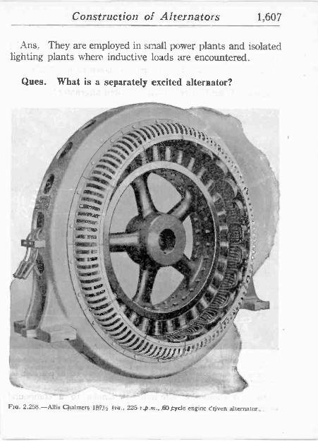
Construction of Alternators 1,607
Ans. They are employed in small power plants and isolated lighting plants where inductive loads are encountered.
Ques. What is a separately excited alternator?
...-
1! :.:.
, , ,.? .' y y !s. ah
r ! t6
yy
-
x 't. w,o É
sux.
C s `\' -ir''.-1" í.
r ° r / - ;.s _ . ' , fi r
-:--_-._
--- -.Y.:
Fia. 2,258.-Allis Chalmers' 187y
-..%_
i
kv,., 225 r.p.tn.. 60 cycle engine ¿riven alternator..
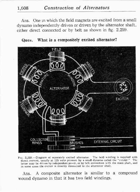
1,608 Construction of Alternators
Ans. One in which the field magnets are excited from a small dynamo independently driven or driven by the alternator shaft, either direct connected or by belt as shown in fig. 2,259.
Ques. What is a compositely excited alternator?
° FIE_LD °
°
COLLECTO RINGS BRUSHES
EXCITER
EXTERNAL CIRCUIT '
FIG. 2,259.-Diagram of separately excited alternator. The field winding is supplied with direct current, usually at 125 volts pressure by a small dynamo called the "exciter." The latter may be driven by independent power, or by belt connection with the main shaft, and in some cases the exciter is directly connected to the alternator shaft.
Ans. A composite alternator is similar to a compound wound dynamo in that it has two field windings.
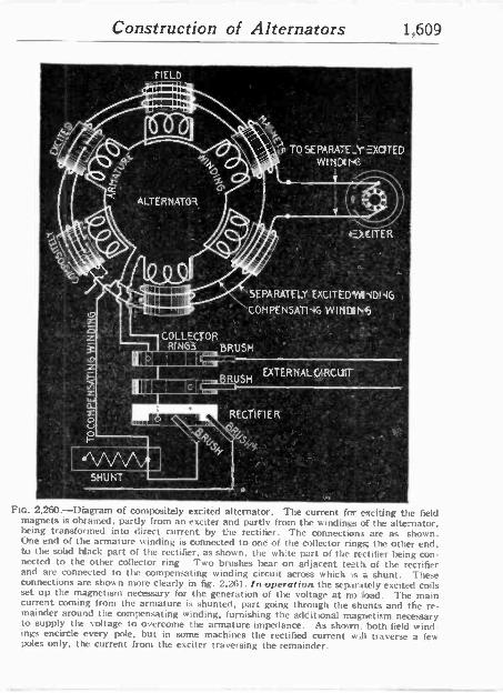
Construction of Alternators 1,609
Y)
.FIELD
auu 4m~1on,r
ALTERNATOR
TO SEPARATE_Y -)(dTED WINCING'
, .+tJITER '
°^ :
SEPARATELY EXCITEDYN9DI16- .
COMPENSATIyG WII1p1.5" ' - ó 411
COLLECTOR ' ^ .
RINGS BRUSH = '
ulNh ! I^ .
( ]
i sBRUSH
EXTERNALIftCUIT
I!p II V RECYÍFIER" ` 'r v o
- 9GS ' i.,o..
GS b
SHUNT
Ftc. 2,260.-Diagram of compositely excitéd alternator. The current far exciting the field magnets is obtained, partly from an exciter and partly from the windings of the alternator, being transformed into direct current by the rectifier. The connections are as shown. One end of the armature winding is connected to one of the collector rings; the other end. to the sold black part of the rectifier, as shown, the white part of the rectifier being con- nected to the other collector ring Two brushes bear on adjacent to th of the rectifier and are connected to the compensating winding circuit across which is a shunt. These connections are shown more clearly in fig. 2,261. /n operation the separately excited coils set up the magnetism necessary for the generation of the voltage at rm load. The main current coming from the armature is shunted, part going through the shunts and the re- mainder around the compensating winding, furnishing the additional magnetism necessary to supply the voltage to overcome the armature impedance. As shown. both field wind- ings encircle every pole, but in some machines the rectified current will traverse a few poles only, the current from the exciter traversing the remainder.
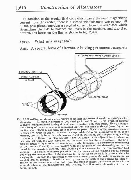
1,610 Construction of Alternators
In addition to the regular field coils which carry the main magnetizing current from the exciter, there is a second winding upon two or upon all
of the pole pieces, carrying a rectified current from the alternator which strengthens the field to balance the losses in the machine, and also if so
desired, the losses on the line as shown in fig. 2,260.
Ques. What is a magneto?
Ans. A special form of alternator having permanent magnets
EXTERNAL ALTERNATING CURRENT CIRCUIT
EXTERNAL RECTIFIED
DIRECT CURRENT
CIRCUIT
INSULATED TEETH
4100° CULLECT O. R RINGS
RECTIFIER
Ftc. 2.261.-Diagram showing construction of rectifier and connections of compositely excited
alternator. The rectifier consists of two castings M and S. with teeth which fit together as shown, being insulated so they do not come in contact with each other. Every alternate tooth being of the same casting is connected together, the same as though joined by a con-
ducting wire. There are as many teeth as there are poles. One end of the armature winding
is connected direct to one of the collector rings, while the other is connected to hl, of the
rectifier, the circuit being through brushes P and Q, the shunt, and compensating winding
to the other collector ring. The brushes P and Q. contact with adjacent teeth, when one
is in contact with the solid black casting the other touches the light casting. The prin-
ciple of action is the same as a commutator, briefly: to reverse the connections terminating at the brushes P and Q. in synchronism with the reversals of the alternating current in-
duced in the armature Binding, thus obtaining direct current for the compensating field
winding. The shunt resistance placed across the compensating winding circuit permits adjusting the compounding of the machine to the circuit on which it is to work, since by varying the resistance the percentage of the total current passing through the compensating winding can be changed. It will he seen by tracing the path of the current for each di-
rection in the armature winding that while the rectifier causes the current to flow in the same direction in the compensating field winding, it still remains alternating in the ex-
ternal circuit.
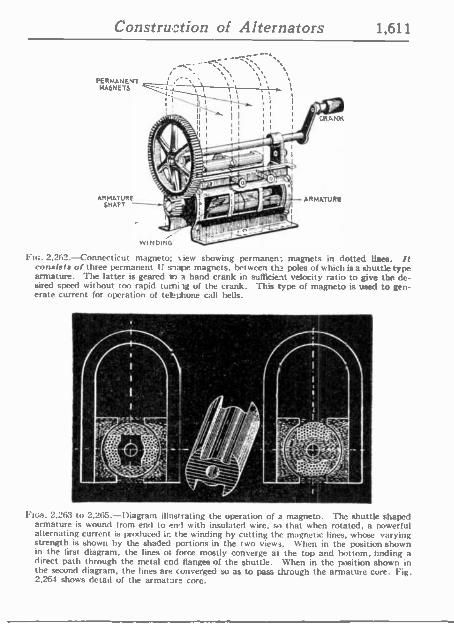
Construction of Alternators 1,611
PERMANENT MA6N ETS
ARMATURE SHAFT
; ~ ':,, ,
f i "-' 1 I ; i 1 \, 1 I 1
I II 1
I
I
II I I I
I I
WINDING
CRANK
ARMATiJR!
FIG. 2,262.-Connecticut magneto: view showing permanen: magnets in dotted lines. It consists of three permanent U site magnets, between the poles of which is a shuttle type armature. The latter is geared t) a hand crank in sufficient velocity ratio to give the de- sired speed without too rapid tumhg of the crank. This type of magneto is used to gen- erate current for operation of teépfione call bells.
Fios. 2,263 to 2,265.-Diagram illustrating the operation of a magneto. The shuttle shaped armature is wound from end to end with insulated wire, so that when rotated, a powerful alternating current is produced ir. the winding by cutting the magnetic lines, whose varying strength is shown by the shaded portions in the two views. When in the position shown in the first diagram, the lines of force mostly converge at the top and bottom, finding a direct path through the metal end flanges of the shuttle. When in the position shown in the second diagram, the lines are converged so as to pass through the armature core. Fig. 2,264 shows detail of the armature core.
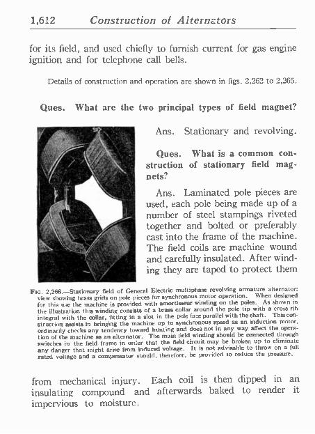
1,612 Construction of Alternators
for its field, and used chiefly to furnish current for gas engine ignition and for telephone call bells.
Details of construction and operation are shown in figs. 2,262 to 2,265.
Ques. What are the two principal types of field magnet?
Ans. Stationary and revolving.
Ques. What is a common con- struction of stationary field mag- nets?
Ans. Laminated pole pieces are used, each pole being made up of a number of steel stampings riveted together and bolted or preferably cast into the frame of the machine. The field coils are machine wound and carefully insulated. After wind- ing they are taped to protect them
FIG. 2,268.-Stationary field of General Electric multiphase revolving armature alternator; view showing brass grids on pole pieces for synchronous motor operation. When designed
for this use the machine is provided with amortisseur winding on the poles. As shown in
the illustration this winding consists of a brass collar around the pole tip with a cross rib integral with the collar, fitting in a slot in the pole face parallel with the shaft. This con-
struction assists in bringing the machine up to synchronous speed as an induction motor,
ordinarily checks any tendency toward hunting and does not in any way affect the opera-
tion of the machine as an alternator. The main field winding should be connected through
switches in the field frame in order that the field circuit may be broken up to eliminate
any danger that might arise from induced voltage. It is not advisable to throw on a full
rated voltage and a compensator should, therefore, be provided to reduce the pressure.
from mechanical injury. Each coil is then dipped in an insulating compound and afterwards baked to render it impervious to moisture.
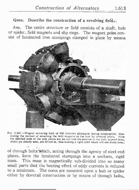
Construction of Alternators 1,613
Ques. Describe the construction of a revolving fields:
Ans. The entire structure or field consists of á sháft, hub or spider, field magnets and slip rings. The magnet poles con- sist of laminated iron stampings clamped in place by means
#
I.
b :, V _ + o `y'"i, ; i : ¡ +i
i4 :, i. ,^^.a.
.
'f
,
;Srs
6..Lr {}
I Afnt .Y]Yl.T
w I n y / u
F.. g -. . ..
r t 41a .pr 0,f, ' =+/ , - d- .
..tiMl i:%.I FIG. 2.267. --Wagner revolving field of 300 kilowatt alternator during construction; illus-
trating the method of attaching the field, magnets to the hub by dovetail joints. After the notched ends of the pole pieces are pu ;hed into the grooves in the huh, tapered keys, which are plainly seen, are driven in, thus making a tight joint which will not shake loose,
of through bolts lvhich, acting through the agency of steel end plates, force the laminated stampings into a uniform, rigid mass. This mass is magnetically sub -divided into so many small parts that the heating effect of eddy currents is reduced to a minimum. The cores are mounted upon a hub. or spider either by dovetail construction or by means of through bolts,
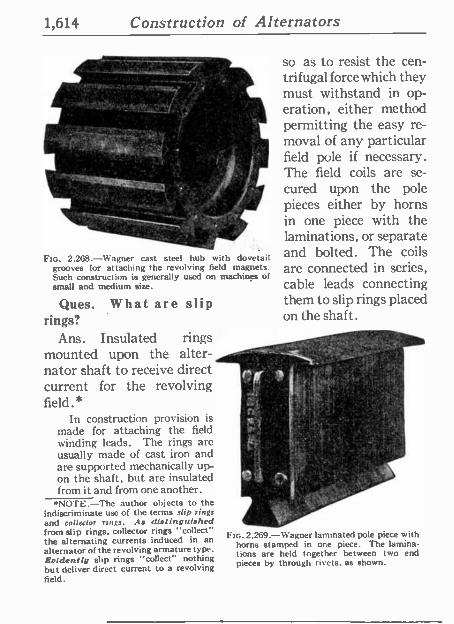
1,614 Construction of Alternators
FIG. 2,268.-Wagner cast steel huh with dovetail grooves for attaching the revolving field magnets. Such construction is generally used on machines of small and medium size.
Ques. What are slip rings?
Ans. Insulated rings mounted upon the alter- nator shaft to receive direct current for the revolving field.*
In construction provision is made for attaching the field winding leads. The rings are usually made of cast iron and are supported mechanically up- on the shaft, but are insulated from it and from one another.
*NOTE.-The author objects to the indiscriminate use of the terms .dip rings and collector rings. As distinguished from slip rings, collector rings "collect" the alternating currents induced in an alternator of the revolving armature type. Evidently slip rings "collect" nothing but deliver direct current to a revolving field.
e
so as to resist the cen- trifugal force which they must withstand in op- eration, either method permitting the easy re- moval of any particular field pole if necessary. The field coils are se- cured upon the pole pieces either by horns in one piece with the laminations, or separate and bolted. The coils are connected in series, cable leads connecting them to slip rings placed on the shaft.
-
.,
Fro. 2,269.-Wagner laminated pole piece with horns stamped in one piece. The lamina- tions are held together between two end pieces by through rivets, as shown.
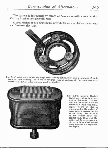
Construction of Alternators 1,615
The current is introduced by means of brushes as with a commutator. Carbon brushes are generally used.
A good design of slip ring should provide for air circulation underneath and between the rings.
Ftc. 2.270.-General Electric slip rings; view showing construction and attachment of cable leads to field winding. They are ao designed that all surfaces of the rings have easy access to the air, in order to obtain good ventilation.
Ftc. 2,271.-General Electric field coil showing one method of winding. The field coils on the larger machines consist of a single strip of flat copper, wound on edge as shown, so that the surface of every turn is exposed to the aír for cooling. The flat sides of the copper strip rest against each other and the entire coil forms a structure of great solidity which can be easily removed for inspection and repair.
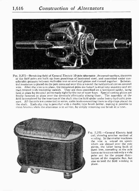
1,616 Construction of Alternators
FIG. 2,272-Revolving field of General Electric 10 pole alternator. In construction, the cores of the field poles are built up from punchings of laminated steel, and assembled under con- siderable pressure between malleable iron or steel end plates and riveted together. Substan- tial insulation is placed on the pole cores and over this is wound the field coils of cot ton covered wire. After the wire is in place, the completed poles are baked to expel any moisture and are then treated with insulating varnish. They are then assembled on a laminated spider, being held in place by dovetail joints made tight by the use of taper keys. Special casting plates are finally fastened in place over the dovetails effectually closing them. The assembly of the field is completed by the insertion of the shaft into the field spider under heavy hydraulic pres- sure. All the coils are connected in series, cable leads connecting them to slip rings placed on the shaft. Each slip ring is provided with a double type brush holder, making it possible to clean brushes while the alternator is in service, by simply removing one brush at a time.
-r"'"":<'8119
I//// 11//I/y»/I 1`I/1//
,N. III il llllllll %n .
lAl
FIG. 2,273.-General Electric field coil, showing another method of winding. In the smaller machines the wire is wound on spools which are slipped over the pole pieces, the latter being built of sheet iron, spreading at the pole face so as to secure not only a wide polar arc for the proper distri- bution of the magnetic flux, but also to hold the field winding in place.
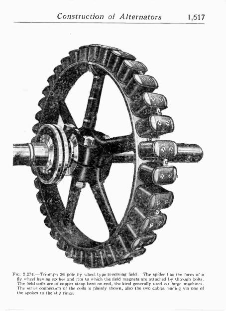
Construction of Alternators 1,617
-
,1
'-74Zt'-, - 15
t
Y, ' .11 ,
1".
'
y
5
t
.:. . ' 1
, , II 11..._". . '45 '13iiirt t" ..07, ' l'' 1 211 '
.1t. . ; '.
. 'V '.1.1.11 I.:. 14 re
1' 3. I ',' , i! Ls, 9 ' ' I. li '..,__.
-....... I. j . -,.. 1 il
411,- -. .....
1, ,...r.-.-:, :-..,-
it,1-,-,,, l''' m ,
k 1
\
N..I1 ',' El f t , J- ^ , ' 'tC", 1
" '' '-' " 9Yi - ' C .1 g: It,- `4. -' ' 11141 '
, -tt r 1, °;,
;5. \ 4,115,121
7.1 k 411
-
1 ,
*
/TO
Ftc. 2,274.-Triumph 36 pole fly wheel type revolving field. The spider has the form of a fly wheel having spokes and rim to which the field magnets are attached by through bolts. The field coils are of copper strap bent on end, the kind generally used ot large machines. The series connection of the coils is plainly shown, also the two cables lear'ing via one of the spokes to the !.lip rings.
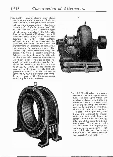
1,618 Construction of Alternators
Flo. 2275.-General Electric multi -phase revolving armature alternator, designed for use in small power plants and isolated lighting plants where inductive loads are encountered. Built for pressures of 120, 240, 480, and 600 volts. These voltages have been recommended by the American Institute of Electrical Engineers, and will cover the needs of any set of conditions , "' ordinarily met with. These standard qe voltages not only permit economical dis- , ' '
tribution, hut they are such that no E
transformers are necessary to reduce the " line pressure for ordinary cases. For .
transmitting power relatively long dis- { tances, 600 volts is usually employed. `v I Where there is a demand for 480 volt service, a 480 volt alternator should be se- lected and if lower voltages be also de- 711 F: sired, an auto -transformer may he fur- nished by means of which 240 volts can be obtained. When 120 volt circuits are ;,s - -j4,1 necessary for lighting, etc., the 240 volt pressure can be still further reduced to 120 volts by means of another auto -trans- former. l lowever, this double reduction will rarely be found necessary.
o, F 3 °'']iJ ','
1 , 0
3i i c+ . S
4- "
Y ó 1 ,
Fio. 2,276.-Graybar stationary armature. In this type of arma- ture, the core upon which the winding is placed, is built into the frame as shown, the core teeth projecting inwardly like internal gear teeth, forming a cylindrical chamber for the revolving field. The core is built up of iron, lam- inated and japanned to prevent eddy currents and hysteresis losses. The laminations are rig- idly bolted between two heavy end plates. The armature coils are of copper bar impregnated with insulating compound. They are held in the slots by wedges which allow their ready removal for inspection or repairs.
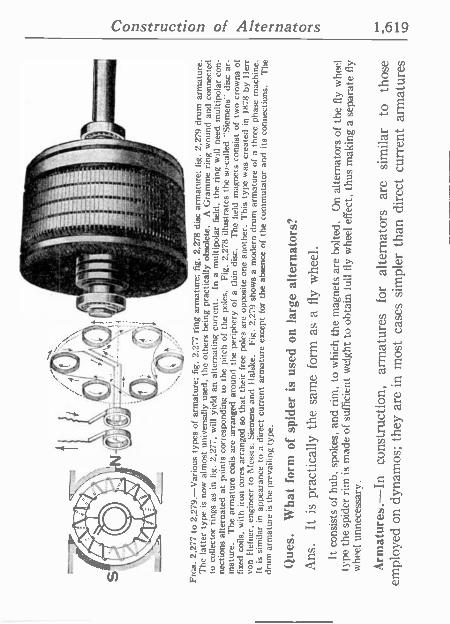
. -
-'+
'' 1
; ;.-
. .
_ ó
o-. --
, FI
GS.
2,2
77 t
o 2,
279.
-Var
ious
type
s of
arm
atur
e; f
ig,
2,27
7 ri
ng a
rmat
ure;
fig
. 2,
278
disc
arm
atur
e; f
ig.
2,27
9 dr
um a
rmat
ure.
T
he l
atte
r ty
pe i
s no
w a
lmos
t un
iver
sally
use
d, t
he o
ther
s be
ing
prac
tical
ly o
bsol
ete.
A
G
ram
me
ring
wou
nd a
nd c
onne
cted
to
col
lect
or r
ings
as
in f
ig.
2,27
7, w
ill
yiel
d an
alte
rnat
ing
curr
ent.
In a
mul
tipol
ar f
ield
, th
e ri
ng w
ill
need
mul
tipol
ar c
on-
nect
ions
alte
rnat
ed a
t po
ints
cor
resp
ondi
ng to
the
pitc
h of
the
pol
es.
Fig.
2,2
78 i
llust
rate
s th
e so
-cal
led
"Sie
men
s" d
isc
ar-
mat
ure.
T
he a
rmat
ure
coils
are
ar
rang
ed a
roun
d th
e pe
riph
ery
of a
thi
n di
sc.
The
fie
ld
mag
nets
con
sist
of
two
crow
ns o
f fi
xed
coils
, w
ith i
ron
core
s ar
rang
ed s
o th
at t
heir
fre
e po
les
are
oppo
site
one
ano
ther
. T
his
type
was
cre
ated
in
1878
by
Iler
r vo
n H
efne
r, e
ngin
eer
to M
essr
s. S
iem
ens
and
I la
lske
. Fi
g. 2
.279
sho
ws
a m
oder
n dr
um a
rmat
ure
of a
thr
ee p
hase
mac
hine
. It
is
sim
ilar
in a
ppea
ranc
e to
a d
irec
t cu
rren
t ar
mat
ure
exce
pt f
or t
he a
bsen
ce o
f th
e co
mm
utat
or a
nd i
ts c
onne
ctio
ns.
The
dr
um a
rmat
ure
is t
he p
reva
iling
typ
e.
Que
s.
Wha
t fo
rm o
f sp
ider
is
used
on
larg
e al
tern
ator
s?
Ans
. It
is
prac
tical
ly t
he s
ame
form
as
a fl
y w
heel
. It
con
sist
s of
hub
, sp
okes
, an
d ri
m,
to w
hich
the
mag
nets
are
bol
ted.
O
n al
tern
ator
s of
the
fly
whe
el
type
the
spi
der
rim
is
mad
e of
suf
fici
ent
wei
ght
to o
btai
n lu
ll fl
y w
heel
eff
ect,
thus
mak
ing
a se
para
te fl
y w
heel
unn
eces
sary
.
Arm
atur
es.-
In
cons
truc
tion,
ar
mat
ures
fo
r al
tern
ator
s ar
e si
mila
r to
th
ose
empl
oyed
on
dyna
mos
; th
ey a
re i
n m
ost
case
s si
mpl
er t
han
dire
ct c
urre
nt a
rmat
ures
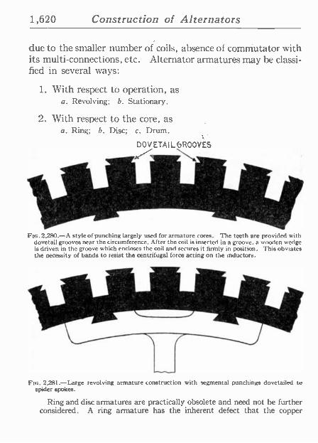
1,620 Construction of Alternators
due to the smaller number of coils, absence of commutator with its multi -connections, etc. Alternator armatures may be classi- fied in several ways:
1. With respect to operation, as a. Revolving; b. Stationary.
2. With respect to the core, as a. Ring; b. Disc; c. Drum.
DOVETAIL bROOVES
Fin. 2280.-A style of punching largely used for armature cores. The teeth are provided with dovetail grooves near the circumference. After the coil is inserted in a groove, a wooden wedge is driven in the groove which encloses the coil and secures it firmly in position. This obviates the necessity of bands to resist the centrifugal force acting on the inductors.
FIG. 2,281.-Large revolving armature construction with segmental punchings dovetailed to spider spokes.
Ring and disc armatures are practically obsolete and need not he further considered. A ring armature has the inherent defect that the copper
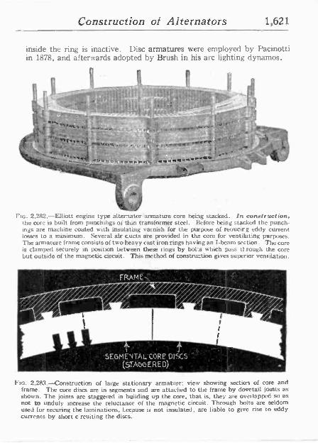
Construction of Alternators 1,621
inside the ring is inactive. Disc armatures were employed by Pacinotti in 1878, and afterwards adopted by Brush in his arc lighting dynamos.
Il l' _.- 1 I
t+ _ _ ' ,f7,:'t rl- .i r F . . 1
,s ^''
.:
"' +,
' ",_ -
o . R 2
;.,::t . I. - " _ ,r .. ,w.nf\.-;`
_4 14 lFibti7rwe^o,w6.1'.. . .
iwVRi II .fYRI0 RAr , :4
1
.0-. .,
I ' t á,.ii i . fAJ `,r -°.iA ' i " -+.
it
t IG. 2.282.-Elliott engine type alternator armature core being stacked. In construction, the core is built from punchings of thin transformer steel. Before being stacked the punch- ings are machine coated with insulating varnish for the ptrpoee of reoucirg eddy current losses to a minimum. Several air cucts are provided in thy core for ventilating purposes. The armature frame consists of two heavy cast iron rings havitg an I-beam section. The core is clamped securely in position between these rings by bol -s which pass tt.rough the core but outside of the magnetic circuit. This method of constru_tion gives superior ventilation.
SEGMEvTACCORE DISCS ..'' - ''.' ° (STAGGERED)," .
FIG. 2,283.-Construction of large stationary armature; view showing section of core and frame. The core discs are in segments and are attached to the frame by dovetail joints as shown. The joints are staggered in building up the core, that is, they are overlapped so as not to unduly increase the reluctance of the magnetic circuit. Through bolts are seldom used for securing the laminations, tecause ii not insulated, are liable to give rise to eddy currents by short c'rcuiting the discs.
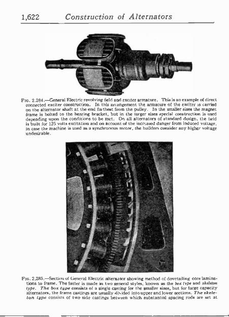
1,622 Construction of Alternators
- +,-r- ' p
..9.4171a4e"
_. - l . . . , r'.
FIG. 2.284.-General Electric revolving field and exciter armature. This is an example of direct connected exciter construction. In this anangement the armature of the exciter is carried on the alternator shaft at the end farthest from the pulley. In the smaller sizes the magnet frame is bolted to the bearing bracket, but in the larger sizes special construction is used depending upon the conditions to be met. On all alternators of standard design, the field is built for 125 volts excitation and on account of the incrtased danger from induced voltage. in case the machine is used as a synchronous motor, the builders consider any higher voltage undesirable.
lú r.J . , ' .
+v S "5".o.
,.
FIG. 2,285.-Section of General Electric alternasor showing method of dovetailing core lamina- tions to frame. The latter is made in two general styles, known as the box type and skeleton type. The box type consists of a single casting for the smaller sizes, but for large capacity alternators, the frame castings are usually divided into upper and lower sections. The skele- ton type consists of two side castings between which substantial spacing rods are set at
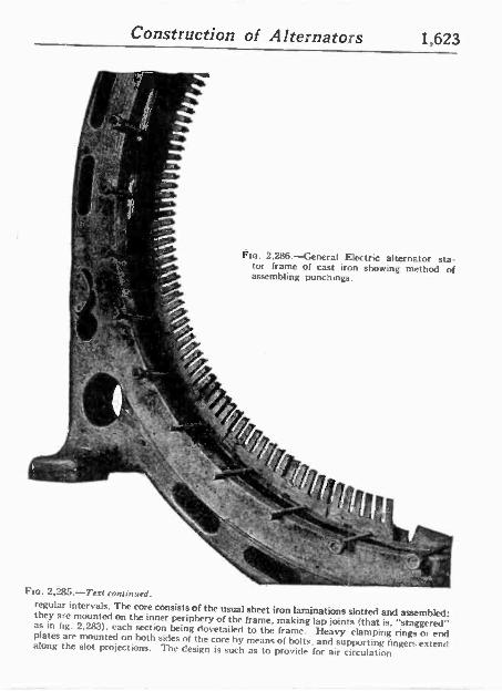
Construction of Alternators 1,623
Fro. 2,286.-General Electric alternator sta- tor frame of cast iron showing method of assembling punchings.
G o}4(/ Cr? .\ ''oile
. 4 a ,
o ' 1E1 Fro. 2,j85.-Text continued.
regular intervals. The core consists of the usual sheet iron laminations slotted and assembled: they are mounted on the inner periphery of the frame, making lap joints (that is, "staggered" as in fig. 2283), each section being dovetailed to the frame. Heavy clamping rings or end plates are mounted on both sides of the core by means of bolts. and supporting fingers extend along the slot projections. The design is such as to provide for air circulation
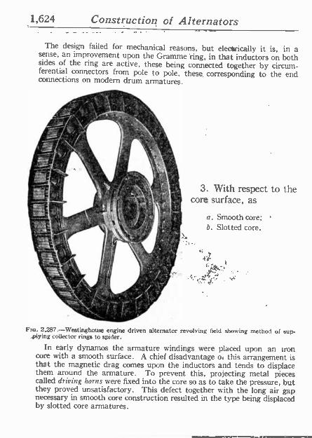
1,624 Construction of Alternators
The design failed for mechanical reasons; but electrically it is, in a sense, an improvement upon the Gramme.'ring, in that inductors on both sides of the ring are active, these being connected together by circum- ferential connectors from pole to pole, these, corresponding to the end connections on modern drum armatures.
.j r h .
1y
3. With respect to the core surface, as
a. Smooth core; b. Slotted core.
Fro. 2,287.-Westinghouse engine driven alternator revolving field showing method of sup- . plying collector rings to spider.
In early dynamos the armature windings were placed upon an iron core with a smooth surface. A chief disadvantage or this arrangement is that the magnetic drag comes upon the inductors and tends to displace them around the armature. To prevent this, projecting metal pieces called driving horns were fixed into the core so as to take the pressure, but they proved unsatisfactory. This defect together with the long air gap necessary in smooth core construction resulted in the type being displaced by slotted core armatures.
Construction of Alternators 1,625
A slotted core is one whose surface is provided with slots or teeth which carry the inductors, as shown in the accompanying illustrations, and is the type almost universally used. The inductors are laid in the slots, the sides and bottoms of which are first carefully insulated by troughs of mica - canvas, micánite or other suitable insulating material.
Ques. What are the advantages of slotted core armatures?
Ans. The teeth protect the inductors, retain them in place against the electrical drag and centrifugal force, and the con- struction permits a reduction of air gap to a minimum, thus reducing the amount of copper required for the field.
Windings.-Owing tó the amount of space required to pro- perly present this subject, it is thought best to devote a separate chapter to it.
TEST QUESTIONS
1. What are the three essential parts of an alternator? 2. What three ways are the field magnets excited? 3. What is a self-excited alternator? 4. For what class of service are self -exciting alternators
used? 5. What is a separately excited alternator? 6. What is a compositely excited alternator? 7. What is a magneto? 8. What are the two principal types of field magnet? 9. What is the usual construction of stationary field
magnets?
1,626 Construction of Alternators
10. Describe the construction of a revolving field: 11. What are slip rings? 12. What form of spider is used on large alternators? 13. How are armatures classified; 1, with respect to
operation; 2, with respect to the core; 3, with re- spect to the core surface?
14. Which is the prevailing type of armature? 15. What are the advantages of slotted core armatures?
Transformers 1,627
CHAPTER 52
Transformers The developments in the field of electrical engineering which
have rendered feasible the transmission of high pressure cur- rents over long distances, together with the reliability and effi- ciency of modern generating units, have resulted in notable economies in the generation and distribution of electric current.
This has been accomplished largely by the use of distant water power or the centralization of the generating plants of a large territory in a single power station.
The transformer is one of the essential factors in effecting the economical distribution of electric energy, and may be defined as an apparatus used for changing the voltage and current of an alternating circuit. A transformer consists essentially of:
1. A primary winding; 2. A secondary winding; 3. An iron core.
NOTE.-Michael Faraday in 1831 announced the discovery of the theory of electric mag- netic induction. Many experiments were made in the following years by Henry Masson.. Wright and others. Varley in 1856 described his induction coil with a closed magnetic circuit consisting of a bundle of wires with ends bent back on the outside of the copper coil. This was the nearest approach to the laminated core of the modern transformers. A little later Zipernowski, Deri and lilafely did some very important work on transformers and alter- nating current distribution which was of a practical and commercial value. During this period American engineers entered the field and contributed much of practical value, but space will not permit a detailed description. Then followed a period of rapid development. The use of oil as an insulating and cooling medium was adopted and core and copper losses were reduced. Other details such as improved construction, methods of dissipating heat, and increased efficiency and regulation have resulted in the construction of unusually large and high voltage units.
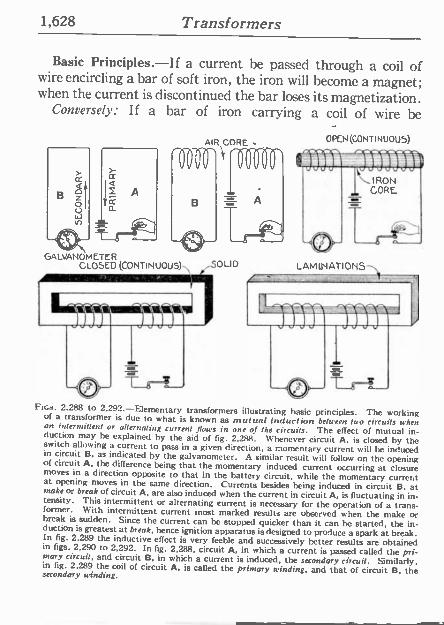
1,628 Transformers
Basic Principles.-If a current be passed through a coil of wire encircling a bar of soft iron, the iron will become a magnet; when the current is discontinued the bar loses its magnetization.
Conversely: If a bar of iron carrying a coil of wire be
OPEN (CONTINUOUS)
GALVANÓMETER OLID CLOSED (CONTINUOUS)
Fins. 2.288 to 2.292.-Elementary transformers illustrating basic principles. The working of a transformer is due to what is known as mutual induction between Sao circuits when an intermittent or alternating current flows in one of the circuits. The effect of mutual in- duction may be explained by the aid of fig. 2.288. Whenever circuit A, is closed by the switch allowing a current to pass in a given direction, a momentary current will be induced in circuit B. as indicated by the galvanometer. A similar result will follow on the opening of circuit A. the difference being that the momentary induced cut rent occurring at closure moves in a direction opposite to that in the battery circuit, while the momentary current at opening moves in the same direction. Currents besides being induced in circuit B. at make or break of circuit A. are also induced when the current in circuit A, is fluctuating in in- tensity. This intermittent or alternating current is necessary for the operation of a trans- former. With intermittent current most marked results are observed when the make or break is sudden. Since the current can be stopped quicker than it can be started, the in- duction is greatest at break, hence ignition apparatus is designed to produce a spark at break. In fig. 2,289 the inductive effect is very feeble and successively better results are obtained in figs. 2.290 to 2,292. In fig. 2,288, circuit A, in which a current is passed called the pri- mary circuit, and circuit B, in which a current is induced, the secondary circuit. Similarly, in fig. 2,289 the coil of circuit A, is called the primary winding, and that of circuit B, the secondary winding.
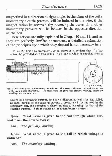
Transformers 1,629
magnetized in a direction at right angles to the plane of the coil a momentary electric pressure will be induced in the wire; if the magnetization be reversed (by reversing the current), another momentary pressure will he induced in the. opposite direction in the coil.
These actions are fully explained in Chaps. 10 and 11, and as they are perfectly familiar phenomena, a detailed explanation of the principles upon which they depend is not necessary here.
From the first two statements given above it is evident that if a bar of iron be provided with two coils of wire, one of which is supplied from a
A_TERNATOR FIG. 2,293.-Diagram of elementary transformer with non -continuous core and connection
with single phase alternator. TI e three essential parts are: primary winding, secondary winding, and an iron core.
source of alternating current, as shown diagrammatically by fig. 2,293, at each impulse of the exciting current a pressure will be induced in the secondary coil, the direction of these impulses alternating like that of the exciting current. This is known as the transformer action.
Ques. What name is given to the coil through which cur- rent from the source flows?
Ans. The primary winding.
Ques. What name is given to the coil in which voltage is induced?
Ans. The secondary winding.
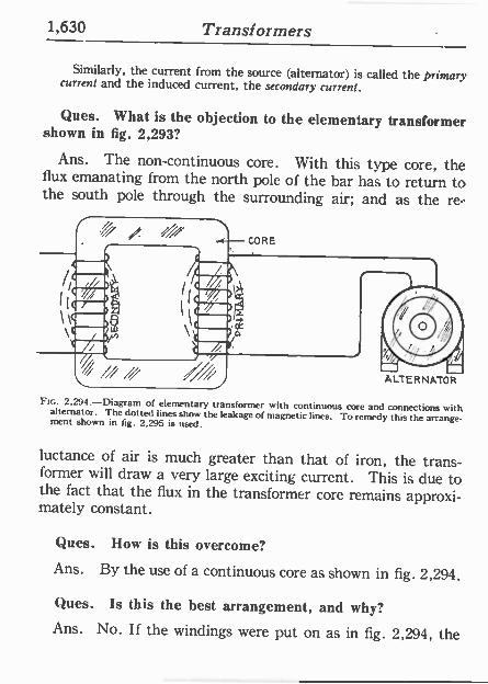
1,630 Transformers
Similarly, the current from the source (alternator) is called the primary current and the induced current, the secondary current.
Ques. What is the objection to the elementary transformer shown in fig. 2,293?
Ans. The non -continuous core. With this type core, the flux emanating from the north pole of the bar has to return to the south pole through the surrounding air; and as the re-
2.294.-Diagram of elementary transformer with continuous core and connections with alternator. The dotted lines show the leakage of magnetic lines. To remedy this the arrange- ment shown in fig. 2.295 is used.
luctance of air is much greater than that of iron, the trans- former will draw a very large exciting current. This is due to the fact that the flux in the transformer core remains approxi- mately constant.
Ques. How is this overcome?
Ans. By the use of a continuous core as shown in fig. 2,294.
Ques. Is this the best arrangement, and why?
Ans. No. If the windings were put on as in fig. 2,294, the
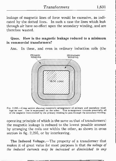
Transformers 1,631
leakage of magnetic lines of force would be excessive, as indi- cated by the dotted lines. In such a case the lines which leak through air have no effect upon the secondary winding, and are therefore wasted.
Ques. How is the magnetic leakage reduced to a minimum in commercial transformers?
Ans. In these, and even in ordinary induction coils (the
PRIMARY WINDING
SECONDARY WINDING
FIG. 2,295.-Cross section showing concentric arrangement of primary and secondary wind- ings on core. One is superposed on the other. This arrangement compels practically all of the magnetic lines created by the primary winding to pass through the secondary winding.
operating principle of which is the same as that of transformers) the magnetic leakage is reduced to the lowest possible amount by arranging the coils one within the other, as shown in cross section in fig. 2,295, or by interleaving.
The Induced Voltage.-The property of a transformer that makes it of great value for most purposes is that the voltage of the induced currents may be increased or diminished to any
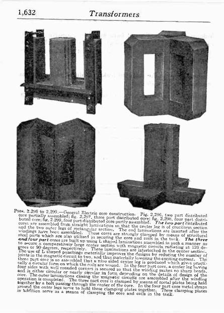
1,632 Transformers
.In .l
!p,Y_ ' "-ti .,_ _ i
t'
7
r r I '`a n, Vi
E_
µ g
,,,.,._ _-,.-_
f
. ;
Ír
,y io
t' ,r -r`- , ` -° r ó . _ _
TI J
F..,; .s.
Inn;. 2.296 to 2,299.-General Electric core construction. Fig. 2,296, two part distributed core partially assembled; fig. 2,297, three part distributed core; fig, 2,298, four part distri- buted core; fig, 2.299, four part distributed core partly assembled. The two part distributed cores are assembled from straight laminations so that the center leg is of cruciform section and the two outer legs of rectangular section. The end laminations are inserted after the windings have been assembled. These cores are strongly clamped by means of structural steel parts which are also utilized in securing the core and coils in the tank. The three and tour part cores are built up using L shaped lamination; assembled in such a manner as to secure a comparatively large center section with magnetic circuits radiating at 120 de- ihrces or 90 degrees, respectively. These laminations are interlocked in the center section. e use of L shaped punching; rneterially improves the designs by reducing the number of joints in the magnetic circuit to two, and thus materially lowering the exciting current. The three part core is so assembled that a nine sided center leg is produced which gives practi- cally a circular form on which the coils are wound. In the four part core, a center leg having four sides with well rounded corners is secured so that the winding makes no sharp bends, and is either circular or nearly circular in form depending on the details of design of the core. The outer laminations closing the magnetic circuits are assembled after the winding operation is completed. The three part core is clamped by means of metal plates being held together by a bolt passing through the center of the core. In the four part core metal straps around the outer legs serve to hold these clamping plates together. 'These clamping plates in addition serve as a means of clamping the core and coils in the tank.
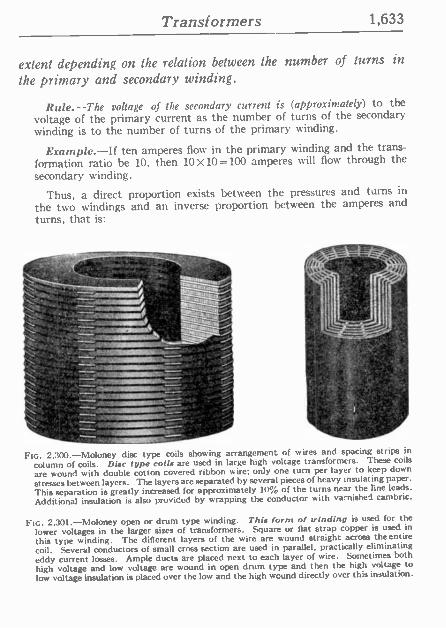
Transformers 1,633
extent depending on the relation between the number of turns in
the primary and secondary winding.
Rule.-The voltage of the secondary current is (approximately) to the voltage of the primary current as the number of turns of the secondary winding is to the number of turns of the primary winding.
Example.-If ten amperes flow in the primary winding and the trans- formation ratio be 10, then 10X10=100 amperes will flow through the
secondary winding.
Thus, a direct proportion exists between the pressures and turns in
the two windings and an inverse proportion between the amperes and
turns, that is:
r x.`, s -T. °
.f=
_ : t=a
_ 4e=Zi z=,
o s
FIG. 2,300.-Moloney disc type coils showing arrangement of wires and spacing strips in
column of coils. Disc type coils are used in large high voltage transformers. These coils
are wound with double cotton covered ribbon wire; only one turn per layer to keep down
stresses between layers. The layers are separated by several pieces of heavy insulating paper.
This separation is greatly increased for approximately 10% of the turns near the line leads.
Additional insulation is also provided by wrapping the conductor with varnished cambric.
Fio. 2,301.-Moloney open or drum type winding. This form of winding is used for the
lower voltages in the larger sizes of transformers. Square or flat strap copper is used in
this type winding. The different layers of the wire are wound straight across the entire
coil. Several conductors of small cross section are used in parallel, practically eliminating eddy current losses. Ample ducts are placed next to each layer of wire. Sometimes both
high voltage and low voltage are wound in open drum type and then the high voltage to low voltage insulation is placed over the low and the high wound directly over this insulation.
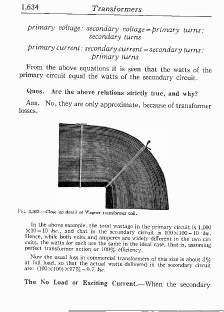
1,634 Transformers
primary voltage: secondary voltage= primary turns: secondary turns
primary current : secondary current = secondary turns :
primary turns From the above equations it is seen that the watts of the
primary circuit equal the watts of the secondary circuit.
Ques. Are the above relations strictly true, and why? Ans. No, they are only approximate, because of transformer
losses.
Fin. 2,302.-Close up detail of Wagner transformer coil.
In the above example, the total wattage in the primary circuit is 1,000 X10 =10 kw., and that in the secondary circuit is 100 X100 =10 kw. Hence, while both volts and amperes are widely different in the two cir- cuits, the watts for each are the same in the ideal case, that is, assuming perfect transformer action or 100% efficiency. Now the usual loss in commercial transformers of this size is about 3% at full load, so that the actual watts delivered in the secondary circuit are: (100X100)X97%=9.7 kw.
The No Load or Exciting Current.-When the secondary
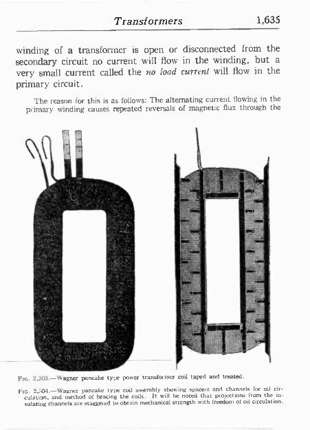
Transformers 1,635
winding of a transformer is open or disconnected from the secondary circuit no current will flow in the winding, but a very small current called the no load current will flow in the primary circuit.
The reason for this is as follows: The alternating current flowing in the primary winding causes repeated reversals of magnetic flux through the
` ' . tF c. o a ' '-+
", l - Yr
. ., - 'ts. ,
4^
.
FIG. 2,503.-Wagner pancake type power transformer coil taped and treated.
2.:O4.-Wagner pancake type coil assembly showing spacers and channels for oil cir- culation, and method of bracing the coils. It will be noted that projections from the in-
sulating channels are staggered tw obtain mechanical strength with freedom of oil circulation.
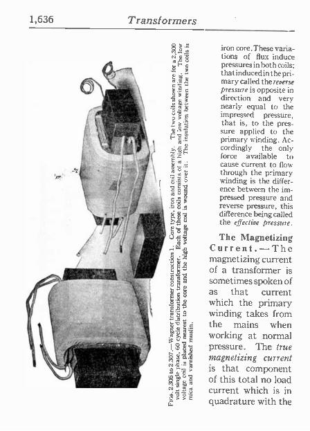
1,636 Transformers
iron core. These varia- tions of flux induce pressures in both coils; that induced in the pri- mary called the reverse pressure is opposite in direction and very nearly equal to the impressed pressure, that is, to the pres- sure applied to the primary winding. Ac- cordingly the only force available to cause current to flow through the primary winding is the differ- ence between the im- pressed pressure and reverse pressure, this difference being called the effective pressure.
The Magnetizing Current.-The magnetizing current of a transformer is sometimes spoken of as that current which the primary winding takes from the mains when working at normal pressure. The true magnetizing current is that component of this total no load current which is in quadrature with the
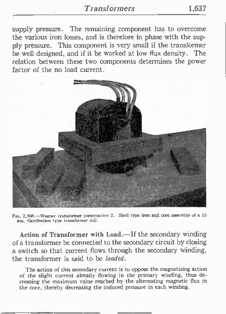
Transformers 1,637
supply pressure. The remaining component has to overcome the various iron losses, and is therefore in phase with the sup- ply pressure. This component is very small if the transformer be well designed, and if it be worked at low flux density. The relation between these two components determines the power factor of the no load current.
nt
Ftc. 2,308.-Wagner transformer construction 2. Shell type iron and core assembly of a 15
kva. distribution type transformer coil.
Action of Transformer with Load.-If the secondary winding of a transformer be connected to the secondary circuit by closing a switch so that current flows through the secondary winding, the transformer is said to be loaded.
The action of this secondary current is to oppose the magnetizing action of the slight current already flowing in the primary winding, thus de- creasing the maximum value reached by the alternating magnetic flux in the core, thereby decreasing the induced pressure in each winding.
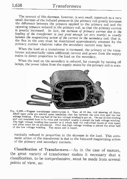
1,638 Transformers
The amount of this decrease, however, is very small, inasmuch as a very small decrease of the induced pressure in the primary coil greatly increases the difference between the pressure applied to the primary coil and the opposing pressure induced in the primary coil, so that the primary current is greatly increased. In fact, the increase of primary current due to the loading of the transformer is just great enough (or very nearly) to exactly balance the magnetizing action of the current in the secondary coil; that is, the flux in the core must be maintained approximately constant by the primary current whatever value the secondary current may have.
When the load on a transformer is increased, the primary of the trans- former automatically takes additional current and power from the supply mains in direct proportion to the load on the secondary. When the load on the secondary is reduced, for example by turning off lamps, the power taken from the supply mains by the primary coil is auto-
'~ --ter
FIG. 2,309-Wagner transformer construction 3. View of 15 kra. coil showing oil ducts. Shell type coils are started upon insulation that lies between the core iron and the low voltage winding. First one half of the low voltage winding is put on. On top of this winding and sell insulated from it by mica and varnished muslin is placed the high voltage winding. The high voltage winding has spacers in it which hold the individual layers of wire apart and allow room for oil circulation. Over this high voltage winding is placed the other half of the low voltage winding. The entire coil is taped.
matically reduced in proportion to the decrease in the load. This auto- matic action of the transformer is due to the balanced magnetizing action of the primary and secondary currents.
Classification of Transformers.-As in the case of motors, the great variety of transformer makes it necessary that a classification, to be comprehensive, must be made from several points of view, as:
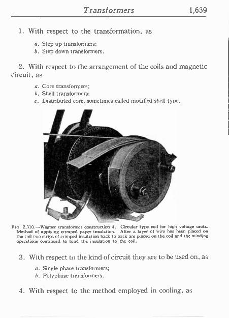
Transformers 1,639
1. With respect to the transformation, as
a. Step up transformers; b. Step down transformers.
2. With respect to the arrangement of the coils and magnetic circuit, as
a. Core transformers; b. Shell transformers; c. Distributed core, sometimes called modified shell type.
2.310.-Wagner transformer construction 4. Circular type coil for high .voltage units. Method of applying crimped paper insulation. After a layer of wire has been placed on the coil two strips of crimped insulation back to back are placed on the coil and the winding operations continued to bind the insulation to the coil.
3. With respect to the kind of circuit they are to be used on, as
a. Single phase transformers; b. Polyphase transformers.
4. With respect to the method employed in cooling, as
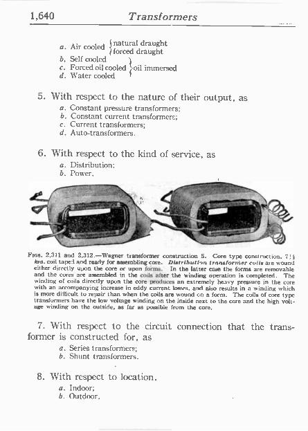
1,640 Transformers
a. Air cooled natural draught forced draught
b, Self cooled c. Forced oil cooled t oil immersed d. Water cooled
5. With respect to the nature of their output, as a. Constant pressure transformers; b. Constant current transformers; c. Current transformers; d. Auto -transformers.
6. With respect to the kind of service, as a. Distribution: b. Power.
/ 1.. i`-n.l. ,'
FIGS. 2,311 and 2,312.-Wagner transformer construction 5. Core type construction. 714 kva. coil taped and ready for assembling core. Distribution transformer coils are wound either directly upon the core or upon forms. In the latter case the forms are removable and the cores are assembled in the coils after the winding operation is completed. The winding of coils directly upon the core produces an extremely heavy pressure in the core with an accompanying increase in eddy current losses, and also results in a winding which is more difficult to repair than when the coils are wound on a form. The coils of core type transformers have the low voltage winding on the inside next to the core and the high volt- age winding on the outside, as far as possible from the core.
7. With respect to the circuit connection that the trans- former is constructed for, as
a. Series transformers; b. Shunt transformers.
8. With respect to location. a. Indoor; b. Outdoor.
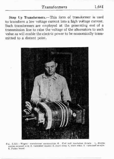
Transformers 1,641
Step Up Transformers.-This form of transformer is used to transform a low voltage current into a high voltage current. Such transformers are employed at the generating end of a transmission line to raise the voltage of the alternators to such value as will enable the electric power to be economically trans- mitted to a distant point.
,!t:v
L' \
t 2 !i 6`
.... _ ft
°
3
i':1'~NF' `.;,'e. _ lé 94!_ . vp'` °' '5,1,-1
rt Yp lt:
oc: ... . , o . [] : .. i1: 'iY \ t r+'Y i,n.-s&j.: tL 1
Ftc. 2,313.-Wagner transformer construction 6. Coil and insulation details. 1, double cotton covered wire; 2, varnished muslin; 3, sheet mica; 4, sheet mica; 5, varnished muslim 6, Fuller board.
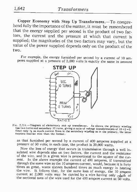
1,642 Transformers
Copper Economy with Step Up Transformers.-To compre- hend fully the importance of the matter, it must be remembered that the energy supplied per second is the product of two fac- tors, the current and the pressure at which that current is supplied; the magnitudes of the two factors may vary, but the value of the power supplied depends only on the product of the two.
For example, the energy furnished per second by a current of 10 am- peres supplied at a pressure of 2,000 volts is exactly the same in amount
STEP UP
RAT10.5
FIG. 2,314 -Diagram of elementary step up transformer. As shown the primary winding has two turns and secondary 10 turns, giving a ratio of voltage transformation of 10+2=-5. Since only '; as much current flows in the secondary winding as in the primary, the latter requires heavier wire than the former,
as that furnished per second by a current of 400 amperes supplied at a pressure of 50 volts; in each case, the product is 20,000 watts.
Now the loss of energy that occurs in transmission through a well in- sulated wire depends also on two factors, the current and the resistance of the wire, and in a given wire is proportional to the square of the cur- rent. In the above example the current of 400 amperes, if transmitted through the same wire as the 10 amperes current, would, because it is forty times as great, waste sixteen hundred times as much energy in heating the wire. It follows that, for the same loss of energy, the 10 ampere current at 2,000 volts may be carried by a wire having only 1715th of the sectional area of the wire used for the 400 ampere current at 50 volts.
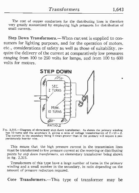
Transformers 1,643
The cost of copper conductors for the distributing lines is therefore very greatly economized by employing high pressures for distribution of small currents.
Step Down Transformers.-When current is supplied to con- sumers for lighting purposes, and for the operation of motors, etc., considerations of safety as well as those of suitability, re- quire the delivery of the current at comparatively low pressures ranging from 100 to 250 volts for lamps, and from 100 to 600 volts for motors.
RATIO.2 Flo. 2,315.-Diagram of elementary step down transformer. As shown the primary winding
has 10 turns and the secondary 2, giving a ratio of voltage transformation of 2 =10 =.2. The current in the secondary being 5 times greater than in the primary will require a pro- portionately heavier wire.
This means that the high pressure current in the transmission lines must be transformed to low pressure current at the receiving or distributing points by step down transformers, an elementary transformer being shown in 1ig. 2,315.
Transformers of this type have a large number of turns in the primary winding and a small number in the secondary, in ratio depending on the amount of pressure reduction required.
Core Transformers.-This type of transformer may be
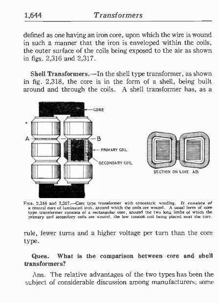
1,644 Transformers
defined as one having an iron core, upon which the wire is wound in such a manner that the iron is enveloped within the coils, the outer surface of the coils being exposed to the air as shown in figs. 2,316 and 2,317.
Shell Transformers.-In the shell type transformer, as shown in fig. 2,318, the core is in the form of a shell, being built around and through the coils. A shell transformer has, as a
SECONDARY COIL
tl finuIIIIIN
SECTION ON LINE AB
FIGS. 2,316 and 2,317.-Core type transformer with concentric winding. It consists of a central core of laminated iron, around which the coils are wound. A usual form of core type transformer consists of a rectangular core, around the two long limbs of which the primary and secondary coils are wound, the low tension coil being placed next the core.
rule, fewer turns and a higher voltage per turn than the core type.
Ques. What is the comparison between core and shell transformers?
Ans. The relative advantages of the two types has been the subject of considerable discussion among manufacturers; some
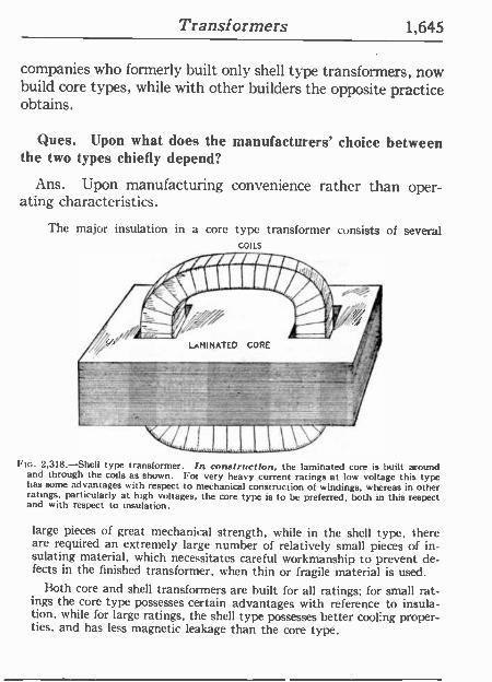
Transformers 1,645
companies who formerly built only shell type transformers, now build core types, while with other builders the opposite practice obtains.
Ques. Upon what does the manufacturers' choice between the two types chiefly depend?
Ans. Upon manufacturing convenience rather than oper- ating characteristics.
The major insulation in a core type transformer consists of several COILS
FIG. 2,318.-Shell type transformer. In construction, the laminated core is built around and through the coils as shown. For very heavy current ratings at low voltage this type has some advantages with respect to mechanical construction of windings, whereas in other ratings, particularly at high voltages, the core type is to be preferred, both in this respect and with respect to insulation.
large pieces of great mechanical strength, while in the shell type, there are required an extremely large number of relatively small pieces of in- sulating material, which necessitates careful workmanship to prevent de- fects in the finished transformer, when thin or fragile material is used.
Both core and shell transformers are built for all ratings; for small rat- ings the core type possesses certain advantages with reference to insula- tion, while for large ratings, the shell type possesses better cooling proper- ties, and has less magnetic leakage than the core type.
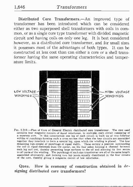
1,646 Transformers
Distributed Core Transformers.-An improved type of transformer has been introduced which can be considered either as two superposed shell transformers with coils in com- mon, or as a single core type transformer with divided magnetic circuit and having coils on only one leg. It is best considered however, as a distributed core transformer, and for small sizes it possesses most of the advantages of both types. It can be constructed at less cost than can either a core or a shell trans- former having the same operating characteristics and temper- ature limits.
LOw VOLTAGE NrC#-i VOLTAGE WINDING'S
FIG. 2,319.-Plan of Core of General Electric distributed core transformer. The core used contains four magnetic circuits of equal reluctance, in multiple; each circuit consisting of a separate core. In this construction one leg of each circuit is built up of two different widths of punchings forming such a cross section that when the four circuits are assembled together they interlock to form a central leg, upon which the winding is placed. The four remaining legs consist of punchings of equal width. These occupy a position surrounding the coil at equal distances from the center, on the four sides; forming a channel between each leg and coil, thereby presenting large surfaces to the oil and allowing its free access to all parts of the winding. The punchings of each size transformer are all of the same length assembled alternately, and forming two lap joints equally distributed in the four corners of the core, thereby giving a magnetic circuit of low reluctance.
Ques. How is economy of construction obtained in de- signing distributed core transformers?
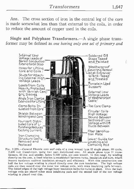
Transformers 1,647
Ans. The cross section of iron in the central leg of the core is made somewhat less than that external to the coils, in order to reduce the amount of copper used in the coils.
Single and Polyphase Transformers.-A single phase trans- former may be defined as one having only one set of primary and
Leads from Coils, Porcelain Lgad
Heavily Protected - Support( with Varnish Cam -_ 4 brie Sleeves. - Angle iron Clarr ps- ExtendedforLiftinq' fps U' +( I ááv Clamp Bolts In- It sulated from Cor¢
Shields Between Windingand Core
Four-part Distri buted Core of L- Punchings Reduces Exciting Current.
Iron Clamping Structure Easily Removed and ,Replaced
Internál' Law - Soldered Da Voltage Leads of - ' Stops Taped Bared Conductor(- j r, ;and Painted; Extend to Oil Stop t" 1, i ' I
t Holes for Lifting .!
A j Weatherproof
Core and Coils q Coveriflq Remov"
,,,,m_ 4 .;] 'fed at Entrance' Studs for Attach r to -rank -Taped' ing External High it and Treated' Voltage Leads ' f
External Lows .Voltage Leads
of Weatherproof ' Cable(
Top Core Clamp,
Circular Coi I's -
High Voltage( Wound Between, Sections of Low Voltage with 011 Ducts Between
Fiber Identifica- tion Plate
Lower Guide for Locating and Clamping Rod
FIG. 2.320.-General Electric core and coils of a core wound type H single phase, 60 cycle. 2.300 volt transformer. using (our part distributed core. All single phase type It trans- formers. 50 koa. and smaller, below 6,000 volts, are core wound. In this range, by winding directly on the core, a fixed relation is established between turns, insulation and core, which insures maximum uniform insulation strength and efficiency. With this construction one half the low voltage winding is placed directly over the core insulation. The high voltage coils are then wound over the inner low voltage coils, with mica insulating pads between. The folded edges of the high voltage layer insulation locks the turns in place. Over the high voltage coils are placed other mica insulating pads and the second half of the low voltage winding is placed over this.
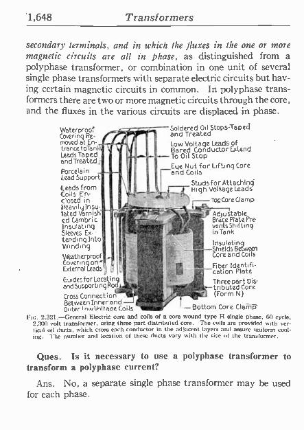
1,648 Transformers
secondary terminals, and in which the fluxes in the one or more magnetic circuits are all in phase, as distinguished from a polyphase transformer, or combination in one unit of several single phase transformers with separate electric circuits but hav- ing certain magnetic circuits in common. In polyphase trans- formers there are two or more magnetic circuits through the core, and the fluxes in the various circuits are displaced in phase.
Waterproof Covering Re- moved at En trance toTank Leads Taped and Treated:
Porcelain Lead Support
Leads from Coils En dosed in Heavily Insu.. fated Varnish ed Cambri C
Insulating Sleeves Ex- tending Into Winding Weatherproof Covering
pj}
Covering o Leads External j t,
Guides for Locating and Supporting Rode
ü' . tir434~-7
Cross Connectionf Between Inner and -I " Oi itor I rivtinttaoe Coils
Soldered Oil Stops -Taped and Treated Low Voltage Leads of Bared Conductor Extend - To Oil Stop Eye Nut for Lifting Core and Coils -
StudsforAttaching High Voltage Leads
Top Core Clamp
Adjustable Brace Plate Pre- vents Shifting in Tank
Insulating Shields Between Core and Coils
Fiber Identifi- cation Plate
Three part Dis- tributed Core Worm N)
au ,;r Bottom Core Clamp
Ftc. 2.321.-General Electric core and coils of a core wound type I -I single phase, 60 cycle, 2,300 volt transformer, using three part distributed core. The coils are provided with ver- tical oil ducts, which crass each conductor in the adjacent layers and assure uniform cool- ing. The number and location of these ducts vary with the size of the transformer.
Ques. Is it necessary to use a polyphase transformer to transform a polyphase current?
Ans. No, a separate single phase transformer may be used for each phase.
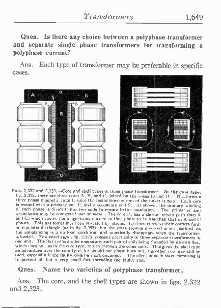
Transformers 1,649
Ques. Is there any choice between a polyphase transformer and separate single phase transformers for transforming a polyphase current?
Ans. Each type of transformer may be preferable in specific cases.
lg>_, e .
L . ./! .
p
Al
q, .},11.
l
/ i¡F. 1 .
N. -:.- f I
.- . ..,...... '
i , l .
,
0'4'1 'i:iu.. 1r otl..._.T , ,_a ',_
--,24 \ ..o . i -.' .. ;s ---.",.:< L ,
FIGS. 2.322 and 2,323.-Core and shell types of three phase transformer. In the core type. fig. 2,322, there are three cores A, B. and C, joined by the yokes D and D'. This forms a three phase magnetic circuit. since the instantaneous sum of the fluxes is zero. Each core is wound with a primary coil Y. and a secondary coil S. As shown. the primary winding of each phase is divide'l into two coils to ensure better insulation. The primar es and secondaries may he connected star or n,rsi,. The core R, has a shorter return path than A and C, which causes the magnetizing current in that phase to he less than that in A and C phases. This has sometimes been obviated by placing the three cores so their corners form an equilateral triangle (as in fig. 2,297), but the extra trouble involved is not justified, as the unbalancing is a no load condition, and practically disappears when the transformer is loaded. The shell type. fig. 2.323, consists practically of three separate transformers in one unit. The flux paths are here separate, each pair of coils being threaded by its own flux. which does not, as in the core type, return through the other coils. This gives the shell type an advantage over the core type. for should one phase burn out, the other two may still be used, especially if the faulty coils he short circuited. The effect of such short circuiting is to prevent all but a very small flux threading the faulty coil.
Ques. Name two varieties of polyphase transformer.
Ans. The core, and the shell types are shown in rigs. 2,322 and 2,323.
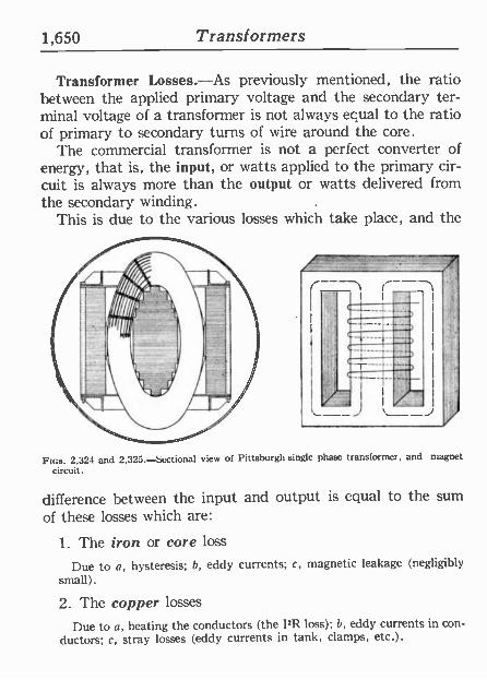
1,650 Transformers
Transformer Losses.-As previously mentioned, the ratio between the applied primary voltage and the secondary ter- minal voltage of a transformer is not always equal to the ratio of primary to secondary turns of wire around the core.
The commercial transformer is not a perfect converter of energy, that is, the input, or watts applied to the primary cir- cuit is always more than the output or watts delivered from the secondary winding.
This is due to the various losses which take place, and the
FIGS. 2,321 and 2,325.-Sectional view of Pittsburgh single phase transformer, and magnet
circuit.
difference between the input and output is equal to the sum
of these losses which are:
1. The iron or core loss
Due to a, hysteresis; b, eddy currents; c, magnetic leakage (negligibly small).
2. The copper losses
Due to a, heating the conductors (the hR loss); h, eddy currents in con- ductors; c, stray losses (eddy currents in tank, clamps, etc.).
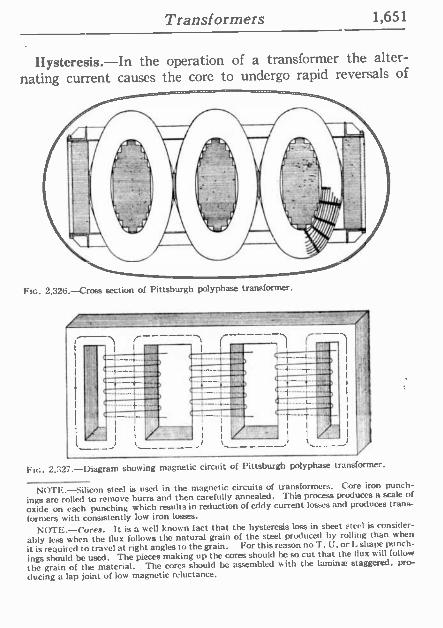
Transformers 1,651
Hysteresis.-In the operation of a transformer the alter- nating current causes the core to undergo rapid reversals of
Ftc. 2,326. --Cross section of Pittsburgh polyphase transformer.
FIG. 2,327.-Diagram showing magnetic circuit of Pittsburgh polyphase transformer.
NOTE.-Silicon steel is used in the magnetic circuits of transformers. Core iron punch-
ings are rolled to remove burrs and then carefully annealed. This process produces a scale of
oxide on each punching which results in reduction of eddy current losses and produces trans-
formers with consistently low iron losses.
NOTE.-cores. It is a well known fact that the hysteresis loss in sheet steel is consider-
ably less when the flux follows the natural grain of the steel produced by rolling than when
it is required to travel at right angles to the grain. For this reason no T, U. or L shape punch-
ings should be used. The pieces making up the cores should be so cut that the flux mill follow
the grain of the material. The cores should be assembled aith the lamina: staggered, pro-
ducing a lap joint of low magnetic reluctance.
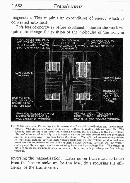
1,652 Transformers
magnetism. This requires an expenditure of energy which is converted into heat.
This loss of energy as before explained is due to the work re- quired to change the position of the molecules of the iron, in
ü MICA INSULATING PADS ....HIGH VOLTAGE 'H'GH VOLTAGE. TO'. '. " BETWEEN HIGH AND LOW LEADSIN : LOW VOLTAGE VOLTAGE AND BETWEEN .. ADJACENT --. CREEPAGE DISTANCE
. SECTIONS OF HIGH VOLTAGE QUADRANTS ' cq
LI
' LOW VOLTAGE WINDING
HIGH VOLTAGE END TURNS ARE REMOTE FROM LOW VOLTAGE
HIGH VOLTAGE. LEADS WELL ANCHORED IN PLACE BY FULLLENGTH OF WINDING
HIGH' VOLTAGE' "W INDING
INSULATION BETWEEN
WINDINGS '. ANO THE
CORE
HEAVILY INSI»..ATED CROSS CONNECTIONS BETWEEN HALVEScOFHIGH VOLTAGE WINDING
Ftc. 2,328.-General Electric split coil construction for small distribution and power trans formers. The diagram shows the improved method of winding high voltage coils. The incoming high voltage leads enter the winding between the two halves of the high voltage coils, and what would normally be the outside leads of the high voltage coils are connected together as a cross over, thus completing the circuit. The split coil construction provides the maximum distance between high voltage leads and the low voltage winding and also introduces the impedance of one half the high voltage winding between the low voltage winding and the voltage disturbance entering from the high voltage line. The object of this is to secure the maximum insulation strength between the high voltage and low voltage windings.
reversing the magnetization. Extra power then must be taken from the line to make up for this loss, thus reducing the effi- ciency of the transformer.
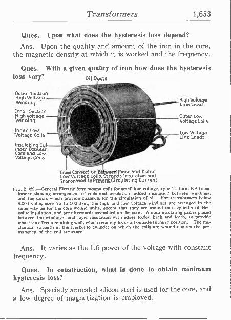
Transformers 1,653
Ques. Upon what does the hysteresis loss depend?
Ans. Upon the quality and amount of the iron in the core; the magnetic density at which it is worked and the frequency:
Ques. With a given quality of iron how does the hysteresis loss vary? Oil Ducts
Outer Section High Voltage Winding
Inner Section High Voltage Winding
inner Low Voltage Coils
Insulating Cyr under Between' Core and Low Voltage Coils
' High Voltage : Line Lead
Cross Connection B eranner and Outer Low -Voltage Coils. Strands Insulated and Transposed to PrgygfttCi rcu latinq Current
Flc. 2,329.-General Electric form wound coils for small low voltage, type H. form KS trans- former showing arrangement of coils and insulation, added insulation between windings. and the ducts which provide channels for the circulation of oil. For transformers below 6.000 volts, sizes 75 to 500 kva., the high and low voltage windings are arranged in the same way as for the core wound units, except that they are wound on a cylinder of Her- kolite insulation, and are afterwards assembled on the core. A mica insulating pad is placed between the windings, and layer insulation with edges folded back and forth, to provide what is in effect a retaining wall, which securely locks all outside turns in position. The me- chanical strength of the Herkolite cylinder on which the coils are wound assures the per- manency of the coil structure.
Outer Low Voltage Coils
Low Voltage' Line ,.eads,
Ans. It varies as the 1.6 power of the voltage with constant frequency.
Ques. In construction, what is done to obtain minimum hysteresis loss?
Ans. Specially annealed silicon steel is used for the core, and a low degree of magnetization is employed.
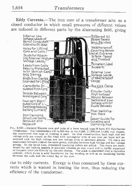
1,654 Transformers
Eddy Currents.-The iron core of a transformer acts as a closed conductor in which small pressures of different values are induced in different parts by the alternating field, giving
Internal Low Voltage Leads of Is , - r Stops Taped Bared Conduetoñ -y Ina Painted Extend to Oil Stop '
t ¡ e W therproof Holes for Lift inq f'', i 1 Covering Remov- Core and Coils i :e Ved et Entrance Studs for Attach= '' ''''.'dtoTank-Taped'
inq External High=-, ' and Treated' Voltage Leads Leádsfrom Coils _Porcelain Lgad
Heavily Protected -- _ .vw. Support( With Varnish Cam t. External LoW bra Sleeved
1 I . IVoltage Leada,_ ` of Weatherproof
Cable(
-sf , -/- -Top Core Clamp t High Voltage(
f
CircularCoils-
111 Wound Between Sections of Low Voltage with Oi 1
Ducts Between
'Fiber Ides tifica tion Plate
Angle iron Clarñps. Extended for Lifting Clamp Bolts Irt sulated from Core
Shields Between..., Winding and Core I'
tour --part Distri-' buted Core of L- PunchingsReduce5 Exciting Current! Iron Clamping .
Structure Eaily' Removedend Replaced
o
---,SoTdered Oil
Lower Guidé for ----,'Locating and
Clamping Rod 2,330. -General Electric core and coils of a form wound type H form KS distribution
transformer. For transformers 150 to 500 kra. in the 6,006, 11,000 and 13,200 volt classes, The interleaved disc type of winding is used. In this construction both high and low voltage coils are wound as flat discs with rectangular wire of one turn per layer and as- sembled with the high voltage and low voltage coils in alternate groups. Oil ducts are maintained between coils of the same group, and also between high voltage and low voltage groups. In the latter case, pressboard insulating collars are added. The ducts are main- tained by self locking spacers in accurate columns so that every coil is rigidly supported at frequent intervals directly by the end clamps. The stack is assembled over a Herkolite cylinder, which forms a solid foundation for the winding as well as an insulating barrier between the coils and the center leg of the core.
rise to eddy currents. Energy is thus consumed by these cur- rents which is wasted in heating the iron, thus reducing the efficiency of the transformer.
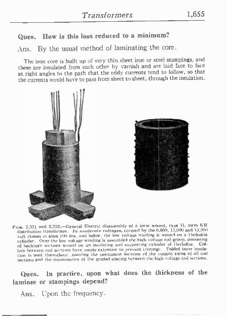
Transformers 1,655
Ques. How is this loss reduced to a minimum?
Ans. By the usual method of laminating the core.
The iron core is built up of very thin sheet iron or steel stampings, and these are insulated from each other by varnish and are laid face to face
at right angles to the path that the eddy currents tend to follow, so that the currents would have to pass from sheet to sheet, through the insulation.
T.
r2s . - .y R't° -r,
FIGS. 2,331 and 2,332.-General Electric disassembly of a form wound, type 1-1. form KR distribution transformer. In moderate voltages, covered by the 6,600. 11,000 and 13,200
volt classes in sizes 100 Aro. and below, the low voltage winding is wound on a Herkolite cylinder. Over the low voltage winding is assembled the high voltage coil group, consisting
of backturn sections wound on an insulating and supporting cylinder of Herkolite. Col- lars between coil sections have ample extension to prevent creepage. Folded layer insula-
lion is used throughout, assuring the permanent location of the outside turns of all coil
sections and the maintenance of the graded spacing between the high voltage coil sections.
Ques. In practice, upon what does the thickness of the laminae or stampings depend?
Ans. Upon the frequency.
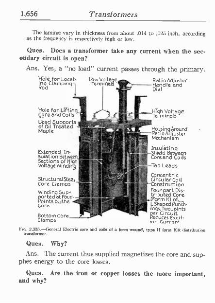
1,656 Transformers
The laminae vary in thickness from about .014 to .025 inch, according as the frequency is respectively high or low.
Ques. Does a transformer take any current when the sec- ondary circuit is open?
Ans. Yes, a "no load" current passes through the primary. Halé for Locat- Low Voltage - iriq Clamping 1 Terminals,' ?, Rod
n
Hole for Lifting- '., ..-High Volta9C Core and Coils 1!`' . x Te-minals Lead Supports -
- y of Oil Treated -11-,,,.5";-. f#,° HosingAround Maple
R-atio Adjuster Hendle and Dial
Extended In sulationBetween, Sections of High
,-Ra=ioAdjuster 4« t.; aj'o- Mechanism
,1.. VoltageVVindin 1 ̀
:' Insulating It ` Shield Betwe¢ñ N,p a Core and Coils
+I' ;. Tao Lads - Concentric
Structural St¢2t ,. _ ' 'lI CircularCoil Core Clamps - -7-Construction
ó
Winding Sup-,,'. '
ported at Four- -';= Points by the -'' e
Core
.11--.°10 Bottom Core_ .
Clamps
Four part Dis- tri outed Core
- .1..(Form K) of L Shaped Punch-
' '
incs.TwoJoints per Circuit Reduces Excit- ing Current
FIG. 2.333.-General Electric core and coils of a form wound, type H form KR distribution transformer.
Ques. Why?
Ans. The current thus supplied magnetizes the core and sup- plies energy to the core losses.
Ques. Are the iron or copper losses the more important, and why?
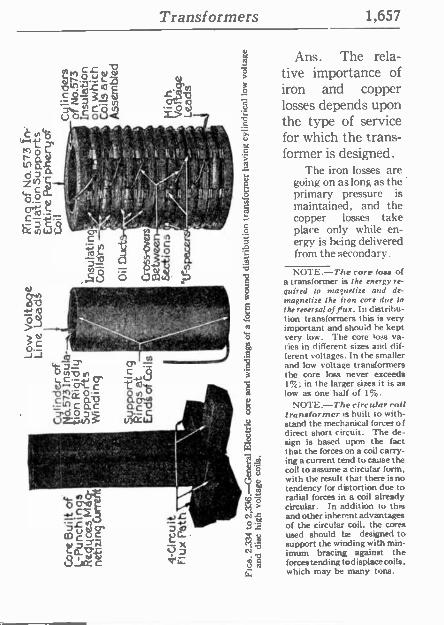
Transformers 1,657
OJ / d - h
-J -I y
Y - _
... Y .
OT .
.....r.........<
Er. O- iY r tn c ñc
1>'"=n.::
Ans. The rela- tive importance of iron and copper losses depends upon the type of service for which the trans- former is designed.
The iron losses are going on as long as the primary pressure is maintained, and the copper losses take place only while en- ergy is being delivered from the secondary.
NOTE.-The core loss of a transformer is the energy re- quired to magnetize and de- magnetize the iron con due to the reversal of flux. In distribu- tion transformers this is very important and should he kept very low. The core loss va- ries in different sizes and dif- ferent voltages. In the smaller and low voltage transformers the core loss never exceeds 1%; in the larger sizes it is as low as one half of 1%.
NOTE.-The circular coil transformer is built to with- stand the mechanical forces of direct short circuit. The de- sign is based upon the fact that the forces on a coil carry- ing a current tend to cause the coil to assume a circular form, with the result that there is no tendency for distortion due to radial forces in a coil already circular. In addition to this and other inherent advantages of the circular coil, the cores used should he designed to support the winding with min- imum bracing against the forces tending tod isplace coils, which may be many tons.
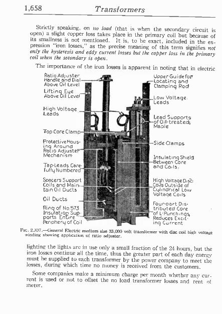
1,658 Transformers
Strictly speaking, on no load (that is when the secondary circuit is open) a slight copper loss takes place in the primary coil but because of its smallness is not mentioned. It is, to be exact, included in the ex- pression "iron losses," as the precise meaning of this term signifies not only the hysteresis and eddy current losses but the copper loss in the primary coil when the secondary is open.
The importance of the iron losses is apparent in noting that in electric Ratio Adjuster Upper Guidefot Handle and Dial !+ -Locating and Above Oil Level
rt ' Clamping Rod Lifting Eye Above Oil Level
High Voltage Leads
Top Core Clamp
ProtectiveHous- ,. -
ing Around It'
Ratio Adjuster'% Mechanism
Tap -Leads Care- fully Numbered
Spacers Support I Coils and Main-
tain OilDucts
Oil Ducts _F _:ur - I
i
Ring of No.573 !
lnsulatioD Sup- ports Entire yid Periphery of Coil
_Low Voltage, Leads
Leed Supports M1 ofOiltreetedi
Maple,
Side Clamps
Insulating Shield -Between Core
and Coils,
High Voltage Disc: Coils Outside of
T1' Low Voltage Coils
Four-part Dis- tributed Core of LPunchingqsi
3 ' a Reduces Exist- u ing Current
Ftc. 2.337.-General Electric medium size 33,000 volt transformer with disc coil high voltage winding showing application of ratio adjuster.
lighting the lights are in use only a small fraction of the 24 hours, but the iron losses continue all the time, thus the greater part of each day energy must he supplied to each transformer by the power company to meet the losses, during which time no money is received from the customers.
Some companies make a minimum charge per month whether any cur- rent is used or not to offset the no load transformer losses and rent of meter.
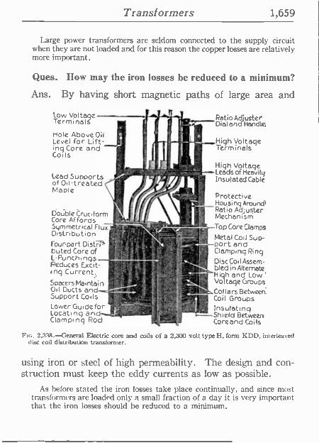
Transformers 1,659
Large power transformers are seldom connected to the supply circuit when they are not loaded and for this reason the copper losses are relatively more important.
Ques. How may the iron losses be reduced to a minimum?
Ans. By having short magnetic paths of large area and
Low Voltage Terminals
Hole Above Oil Level for Lift- ing Core and Coils
Lead Supports of Oil treated Maple
Double Cruciform Core Affords ,
Symmetrical Flux.: Distribution Four-part Distrh buted Core of 1-Punchings Reduces Excit- ing Current, Spacers Maintain Oil Ducts and-- - Support Coils Lower Guide for Locating Clamping ROd
Patio Adjuster l < DialendJHandlé
11-. High voltage !Terminals
High Voltage Leads of Heavily Insulated Cable
Protective Housing Around' Ratio Adjuster Mechanism Top Core Clamas
Metal Coil Sup - 4 Port and Clamping Ring.
DiscCoilAssem- bled in Alternate
' "Hi h and Low `
Voltage Groups Collars Between.
Ir Coil Groups Insulating
=.Shield Between Core and Coils
Fic. 2,3.38.-General Electric core and coils of a 2,300 volt type II, form KDD, imerleaved disc coil distribution transformer.
using iron or steel of high permeability. The design and con- struction must keep the eddy currents as low as possible.
As before stated the iron losses take place continually, and since most transformers are loaded only a small fraction of a day it is very important that the iron losses should be reduced to a minimum.
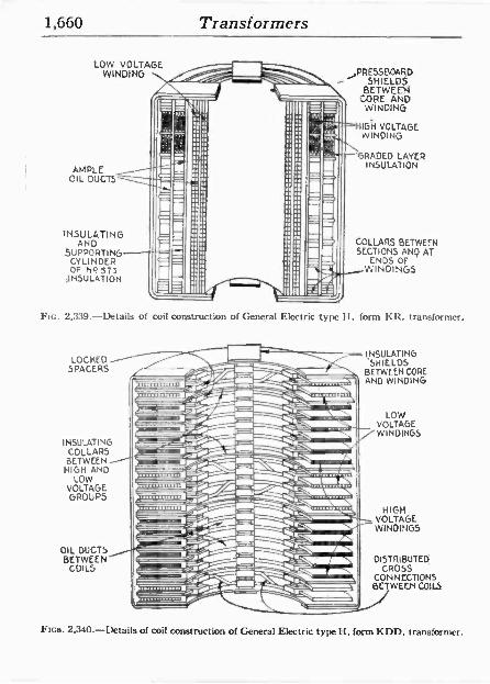
.1
.-
` «~~',--=~`- /i -i- . - t _ !! - \-' r\M i 1f3
='-_i II e
I.
I II
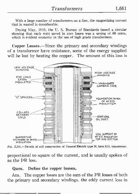
Transformers 1,661
With a large number of -ransformers on a line, the magnetizing current that is wasted is considerable.
During May, 1910, the U. S. Bureau of Standards issued a circular showing that each watt saved in core losses was a saving of 88 cents, which is evident economy in the use of high grade transformers.
Copper Losses.-Since the primary and secondary windings of a transformer have resistance, some of the energy supplied will he lost by heating the copper. The amount of this loss is
LOW WINDING
END COILS®[ EXTRA- INSULATED
"U" SPACERS
LI
ul
1 D
COLLARS, -- BETWEEN
COILS
SUPPORTING
I Il)1
It
CYLINDERS OFNo S7 r--- INSULATION
let
HIGH VOLTAGE WINDING
"---VARNISHED CAMBRIC TAPE
FOUNDATION RINGS OF HQ 573
INSULATION
VERTICAL OIL DUCT
COIL SUPPORT OF No 573 INSULATION
STOP AND BOTTOM
FIG. 2,341.-Details of coil construction of General E ectric type H, form KD, transformer.
proportional to square of the current, and is usually spoken of as the I2R loss.
Ques. Define the copper losses.
Ans. The copper losses are the sum of the I2R losses of both the primary and secondary windings, the eddy current loss in
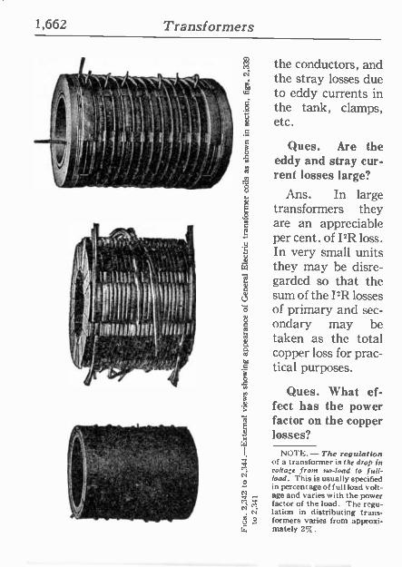
1,662 Transformers
',"1"-f11190 n.\ . \.. . the conductors, and the stray losses due to eddy currents in
s the tank, clamps, etc.
C
Ques. Are the Ñ eddy and stray cur-
rent losses large?
Ans. In large transformers they are an appreciable per cent. of I2R loss. In very small units
w they may be disre- garded so that the sum of the I2R losses of primary and sec- ondary may be
r. taken as the total copper loss for prac- tical purposes.
Ques. What ef- fect has the power
É factor on the copper x losses? w
NOTE.-The regulation of a transformer is the drop in
r? voltage from no-load to full - load. This is usually specified ó in percentage of full load volt- age and varies with the power
g factor of the load. The regu- lation in distributing trans -
2 formers varies from approxi- mately 2%.
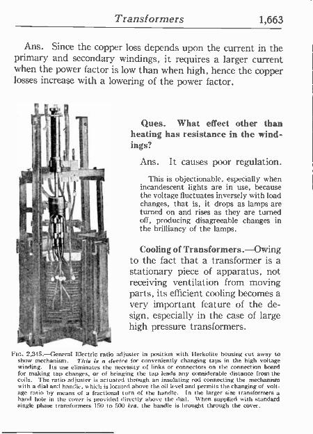
Transformers 1,663
Ans. Since the copper loss depends upon the current in the primary and secondary windings, it requires a larger current when the power factor is low than when high, hence the copper losses increase with a lowering of the power factor.
Ques. What effect other than heating has resistance in the wind- ings?
Ans. It causes poor regulation.
This is objectionable, especially when incandescent lights are in use, because the voltage fluctuates inversely with load changes, that is, it drops as lamps are turned on and rises as they are turned off, producing disagreeable changes in the brilliancy of the lamps.
Cooling of Transformers. Owing to the fact that a transformer is a stationary piece of apparatus, not receiving ventilation from moving parts, its efficient cooling becomes a very important feature of the de- sign, especially in the case of large high pressure transformers.
Ftc. 2,345. ---General Electric ratio adjuster in position with I lerkolite housing cut away to show mechanism. This is a derive for conveniently changing taps in the high voltage winding. Its use eliminates the necessity of links or connectors on the connection board (or making tap changes, or of bringing the tap leads any considerable distance from the coils. The ratio adjuster is actuated through an insulating rod connecting the mechanism with a dial and handle. which is located above the oil level and permits the changing of volt- age ratio by means of a fractional turn of the handle. In the larger size transformers a hand hole in the cover is provided directly above the dial. When supplied with standard single phase transformers 150 to 500 kra. the handle is brought through the cover.
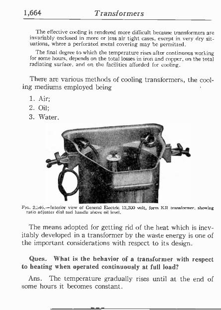
1,664 Transformers
The effective cooling is rendered more difficult because transformers are invariably enclosed in more or less air tight cases, except in very dry sit- uations, where a perforated metal covering may be permitted.
The final degree to which the temperature rises after continuous working for some hours, depends on the total losses in iron and copper, on the total radiating surface, and on the facilities afforded for cooling.
There are various methods of cooling transformers, the. cool- ing mediums employed being
1. Air; 2. Oil;
3. Water.
t Tt k.y o v,. .. .l
h ifJi%_.. .=+'1.
--_.UU
i-. - ._f . . . ,a fr f: i
FIG. 2,:146.-Interior view of General Electric 13,200 volt, form KR transformer, showing ratio adjuster dial and handle above oil level.
The means adopted for getting rid of the heat which is inev- itably developed in a transformer by the waste energy is one of the important considerations with respect to its design.
Ques. What is the behavior of a transformer with respect to heating when operated continuously at full load?
Ans. The temperature gradually rises until at the end of some hours it becomes constant.
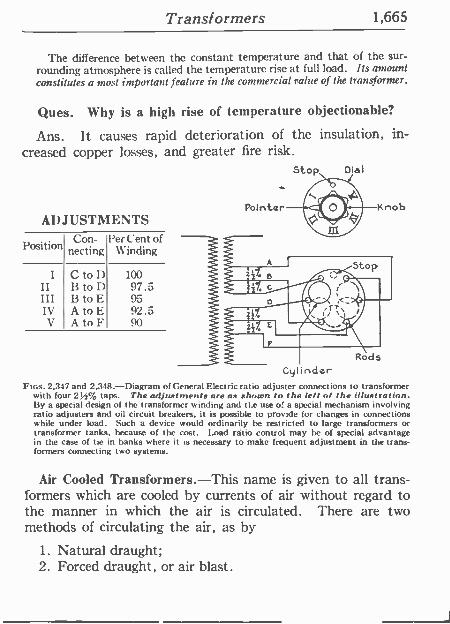
Transformers 1,665
The difference between the constant temperature and that of the sur- rounding atmosphere is called the temperature rise at full load. Its amount constitutes a most important feature in the commercial value of the transformer.
Ques. Why is a high rise of temperature objectionable?
Ans. It causes rapid deterioration of the insulation, in- creased copper losses, and greater fire risk.
Stop
ADJUSTMENTS
Position Con-
necting Per Cent of
Winding
I C to D 100 II 13 to D 97.5 I I I 13 to E 95 IV A to E 92.5 V A to F 90
Cylinder FIGS. 2,347 and 2,348.-Diagram of General Electric ratio adjuster connections to transformer
with four 21.z% taps. The adjustments are as shown to the left of the illustration. By a special design of the transformer si inding and the use of a special mechanism involving ratio adjusters and oil circuit breakers, it is possible to provide for changes in connections while under load. Such a device would ordinarily be restricted to large transformers or transformer tanks, because of the cost. Load ratio control may be of special advantage in the case of tie in banks where it is necessary to make frequent adjustment in the trans- formers connecting two systems.
Dial
Air Cooled Transformers.-This name is given to all trans- formers which are cooled by currents of air without regard to the manner in which the air is circulated. There are two methods of circulating the air, as by
1. Natural draught; 2. Forced draught, or air blast.
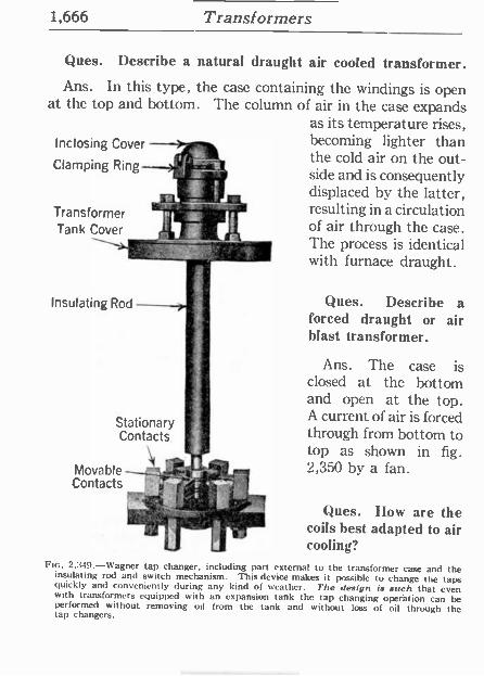
1,666 Transformers
Ques. Describe a natural draught air cooled transformer. Ans. In this type, the case containing the windings is open
at the top and bottom. The column of air in the case expands as its temperature rises,
Inclosing Cover --fir becoming lighter than
Clamping Ring / _ the cold air on the out - Clamping side and is consequently displaced by the latter, resulting in a circulation Transformer
I
Tank Cover ? of air through the case. The process is identical with furnace draught.
Insulating Rod - Stationary Contacts.
Movable Contacts
Ques. Describe a forced draught or air blast transformer.
Ans. The case is closed at the bottom and open at the top. A current of air is forced through from bottom to top as shown in fig. 2,350 by a fan.
Ques. Row are the coils best adapted to air cooling?
FIG. 2.349.-Wagner tap changer. including part external to the transformer case and the insulating rod and switch mechanism. This device makes it possible to change the taps quickly and conveniently during any kind of weather. The design is such that even with transformers equipped with an expansion tank the tap changing operation can be performed without removing oil from the tank and without loss of oil through the tap changers.
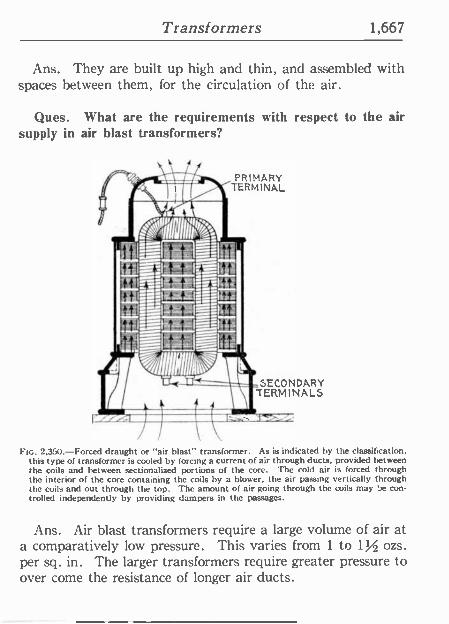
Transformers 1,667
Ans. They are built up high and thin, and assembled with spaces between them, for the circulation of the air.
Ques. What are the requirements with respect to the air supply in air blast transformers?
PRIMARY TERMINAL
SECONDARY TERMINALS
FIG. 2.350.-Forced draught or "air blast" transformer. As is indicated by the classification. this type of transformer is cooled by forcing a current of air through ducts. provided between the coils and between sectionalized portions of the core. The cold air is forced through the interior of the core containing the coils by a blower. the air passing vertically through the coils and out through the top. The amount of aír going through the coils may he con- trolled independently by providing dampers in the passages.
Ans. Air blast transformers require a large volume of air at a comparatively low pressure. This varies from 1 to 1V2 ozs. per sq. in. The larger transformers require greater pressure to over come the resistance of longer air ducts.
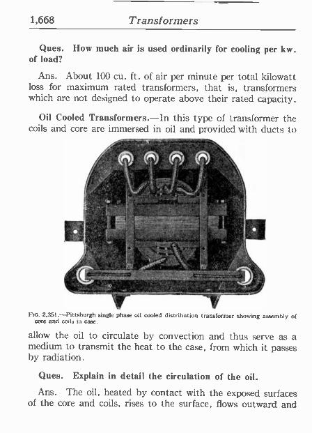
1,668 Transformers
Ques. How much air is used ordinarily for cooling per kw. of load?
Ans. About 100 cu. ft. of air per minute per total kilowatt loss for maximum rated transformers, that is, transformers which are not designed to operate above their rated capacity.
Oil Cooled Transformers.-In this type of transformer the coils and core are immersed in oil and provided with ducts to
=
t t '1
í
c..t-_ :
Ftc. 2.351.-Pittsburgh single phase oil cooled distribution transformer showing assembly of core and coils in case.
allow the oil to circulate by convection and thus serve as a medium to transmit the heat to the case, from which it passes by radiation.
Ques. Explain in detail the circulation of the oil.
Ans. The oil, heated by contact with the exposed surfaces of the core and coils, rises to the surface, flows outward and
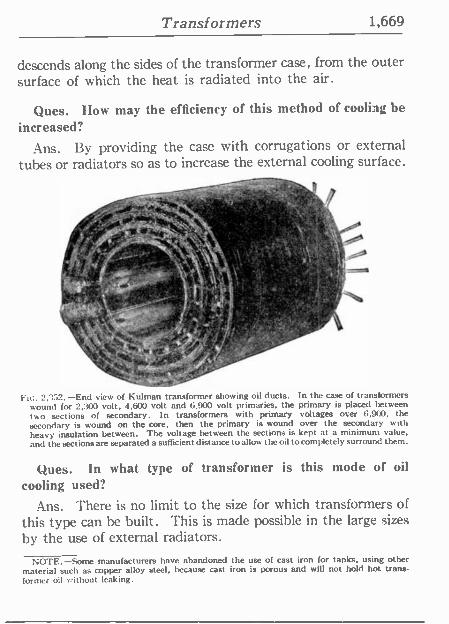
Transformers 1,669
descends along the sides of the transformer case, from the outer surface of which the heat is radiated into the air.
Ques. How may the efficiency of this method of cooling be increased?
Ans. By providing the case with corrugations or external tubes or radiators so as to increase the external cooling surface.
c-- AC, 4a.' 1Rif 3` ̀ =*' ' R 441'
;F 9-.'
J,{7. ;io :
, r .¡.%111...
2,352.-End view of Kulman transformer showing oil ducts. In the case of transformers wound for 2,300 volt, 4,600 volt and 6,900 volt primaries, the primary is placed between bits sections of secondary. In transformers with primary voltages over 6,900, the
secondary is wound on the core, then the primary is wound over the secondary with heavy insulation between. The voltage between the sections is kept at a minimum value, and the sections are separated a sufficient distancé to allow the oil to completely surround them.
Ques. In what type of transformer is this mode of oil
cooling used?
Ans. There is no limit to the size for which transformers of this type can he built. This is made possible in the large sizes by the use of external radiators.
NOTE.-Some manufacturers have abandoned the use of cast iron for tanks, using other material such as copper alloy steel, because cast iron is porous and will not hold hot trans- former oil without leaking.
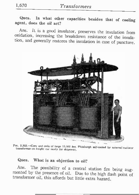
1,670 Transformers
Ques. In what other capacities besides that of cooling agent, does the oil act?
Ans. It is a good insulator, preserves the insulation from oxidation, increasing the breakdown resistance of the insula- tion, and generally restores the insulation in case of puncture.
o.
' , g, ' t. / . '( ) I" I!/' ata,./I'01 ii Il/11.
_ i ,; . a
,., . - ,
M ̂* " I
FIG. 2,353.-Core and coils of large 15,000 kva. Pittsburgh self -cooled by external radiator transformer on freight car ready for shipment.
Ques. What is an objection to oil?
Ans. The possibility of a central station fire being aug- mented by the presence of oil. Due to the high flash point of transformer oil, this affords but little extra hazard.
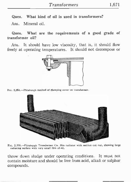
Transformers 1,671
Ques. What kind of oil is used in transformers?
Ans. Mineral oil.
Ques. What are the requirements of a good grade of transformer oil?
Ans. It should have low viscosity, that is, it should flow freely at operating temperatures. It should not decompose or
Fte. 2,354.-Pittsburgh method of clamping cover on transformer.
o`' _,__+..
FIG. 2,355.-Pittsburgh Transformer Co. film radiator with section cut out, showing large radiating surface with very small film of oil.
throw down sludge under operating conditions. It must not contain moisture and should be free from acid, alkali or sulphur compounds.
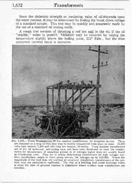
1,672 Transformer's
Since ;the dielectric strength or, insulating value of oil+depends 'upon the water content, it may be determined by finding the break down voltage of a standard sample. This test may be quickly' and accurately made by the use of a standard oil testing outfit.
A rough ,test consists of thrusting a red hot nail in the oil; if the oil "crackle," water is present. ' Moisture may' be removed by raising' the temperature slightly above the boiling point, 212° Fahr., but' the time consumed (several days) is excessive.
gy . . .
- r -, ,!4 ,. s1; --:rr !t R. ,,,._; 1
r
4
sex,
...- _.
Ftc. 2,356.-Three Westinghouse 20 kra. outdoor transformers, for irrigation service. These are mounted on a drag so that they may be readily transported from place to place. 33,000 volts high tension; 2,200 and 440 volts low tension, 50 cycles. These outdoor transformers are of the oil immersed, self -cooling type and have been developed to meet the require- ments for transformers of capacities greater or of voltages higher than are usually found in distribution work. They are in reality distributing transformers for high voltage, out- door installations, single or three phase service, dor voltages up to 110,000. Where the magnitude of the load does not warrant an expensive installation, transformers of the out- door type are particularly applicable. The cost 'of a building and outlet bushings which is often the item of greatest expense Is eliminated where outdoor type transformers, are installed.
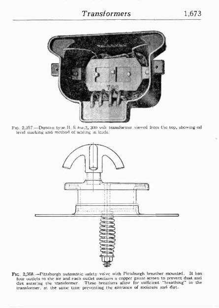
Transformers 1,673
Q2.1: ' 0
le l . _I.3
Fre. 2,357.-Duncan type II, 5 k=a,2, 300 volt transformer viewed from the top, showing oil level marking and method of sealing in leads.
FIG. 2,358.-Pittsburgh automatic safety valve with Pittsburgh breather mounted. It has four outlets to the air and each outlet contains a copper gauze screen to prevent dust and dirt entering the transformer. These breathers allow for sufficient "breathing" in the transformer, at the same time preventing the entrance of moisture and dirt.
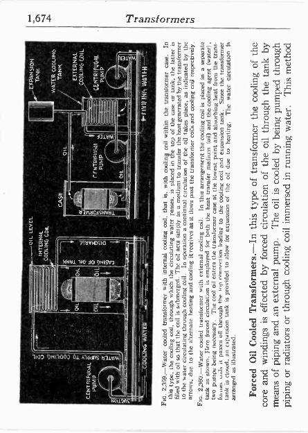
V
: . Z
-
o
INT
ER
NA
L
CO
OL
ING
CO
IL
Y
H
J
CE
NT
RIF
UG
AL
n
NU
MV
9
`b
OIL
tilL
OIL
OIL
a Ó
I -J
....1
.....i
. -L.
,.... .. ' ...
1
1
-CO
OL
ING
. W
AT
ER
. r%
' -4
11"
OIL
L
EV
EL
¡'
'EX
PAN
SIO
N
' u
TA
NK
Yá.
5°: CA
SE
WA
TE
R C
OO
LIN
G
' T
AN
K
EX
TE
RN
AL
-
CO
OL
ING
CO
IL
CE
NT
RIF
UG
AL
PU
MP
' Ik
11
I1.4
1,
I410
11H
Ftc.
2,3
59.-
Wat
er
cool
ed t
rans
form
er w
ith i
nter
nal
cool
ing
coil,
th
at i
s,
with
coo
ling
coil
with
in
the
tran
sfor
mer
eas
e.
In
this
typ
e, t
he c
oolin
g co
il,
thro
ugh
whi
ch
the
circ
ulat
ing
wat
er p
asse
s,
is
plac
ed i
n th
e to
p of
the
cas
e or
tan
k, t
he
latte
r is
fi
lled
with
oil
so t
hat
the
coil
is s
ubm
erge
d.
The
oil
acts
sim
ply
as a
med
ium
to
tran
sfer
the
hea
t gen
erat
ed b
y th
e tr
ansf
orm
er
to t
he w
ater
cir
cula
ting
thro
ugh
cool
ing
coil.
In
ope
ratio
n a
cont
inua
l ci
rcul
atio
n of
the
oil
take
s pl
ace,
as
indi
cate
d by
the
ar
row
s, d
ue t
o th
e al
tern
ate
heat
ing
and
cool
ing
it re
ceiv
es a
s it
flow
s pa
st t
he t
rans
form
er c
oils
and
coo
ling
coil
resp
ectiv
ely.
Ft
c. 2
,360
.-W
ater
coo
led
tran
sfor
mer
with
ext
erna
l co
olin
g co
il.
In t
his
arra
ngem
ent
the
cool
ing
coil
is p
lace
d in
a
sepa
rate
ta
nk a
s sh
own.
H
ere
forc
ed c
ircu
latio
n is
em
ploy
ed f
or b
oth
the
heat
tra
nsfe
r m
ediu
m
(oil)
and
the
coo
ling
agen
t (w
ater
).
two
pum
ps b
eing
nec
essa
ry.
The
coo
l oi
l en
ters
the
tra
nsfo
rmer
cas
e at
the
low
est
poin
t an
d ab
sorb
ing
heat
fro
m
the
tran
s-
fuuu
it
pnax
a of
f th
roug
h th
e to
p en
nnec
tion
lead
ing
to t
he C
oolin
g co
il an
d ex
pans
ion
tank
. Si
nce
the
tran
sfor
mer
ta
nk i
s cl
osed
, an
exp
ansi
on
tank
is
prov
ided
to
allo
w f
or e
xpan
sion
of
the
oil
due
to
heat
ing.
T
he
wat
er
circ
ulat
ion
is
arra
nged
as
illus
trat
ed.
Forc
ed O
il C
oole
d T
rans
form
ers.
-In
this
typ
e of
tra
nsfo
rmer
the
coo
ling
of t
he
core
and
win
ding
s is
eff
ecte
d by
for
ced
circ
ulat
ion
of t
he o
il th
roug
h th
e ta
nk b
y m
eans
of
pipi
ng a
nd a
n ex
tern
al p
ump.
T
he o
il is
coo
led
by b
eing
pum
ped
thro
ugh
pipi
ng o
r ra
diat
ors
or t
hrou
gh c
oolin
g co
il im
mer
sed
in r
unni
ng w
ater
. T
his
met
hod
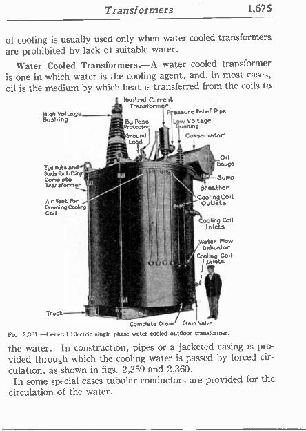
Transformers 1,675
of cooling is usually used only when water cooled transformers are prohibited by lack of suitable water.
Water Cooled Transformers.-A water cooled transformer is one in which water is the cooling agent, and, in most cases,
oil is the medium by which heat is transferred from the coils to
'High .Voltage Búehing
rye Nuts and, Studs for Lifting Complete Transformer
Air Vent for Drawling Cool .% Coil
d
Current Transform r
P essure Relief Pipe
By Pass Low Voltage Protector Bushing
Ground .dill I Coi servator" Lead
-n
--r""" , _oil
se
ice\ VSump Breather
L'CoolingCoil Outlets,
Cooling Coil Inlet's
Water Flow Indicator
a.y` Cooling Colt :. a Inlets.
G Y .
Truck
Complete Dram/ Drain Valve
FIG. 2,361.-General Electric single phase water cooled outdoor transformer.
the water. In construction, pipes or a jacketed casing is pro- vided through which the cooling water is passed by forced cir- culation, as shown in figs. 2,359 and 2,360.
In some special cases tubular conductors are provided for the circulation of the water.
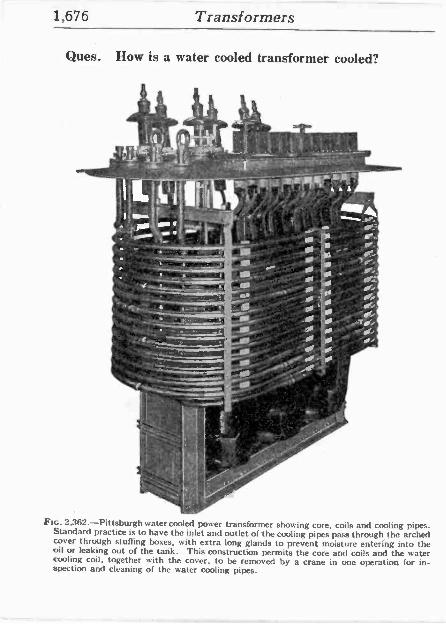
1,676 Transformers
Ques. How is a water cooled transformer cooled?
=~ E -'-'-'...r-.- -.r.
- --- E 4.,f11~1/1:".
E , o
" h
,. 110. F
! -I ' ?if" . ./.
._ / , " d f. '/ ./,. ./ 551 ^fOf/ +/. t.:,,..110-4e r .- Ó -! I s ¿ . - Ir ,
0 -,,: :s "
iC% a
Fin. 2,362.-Pittsburgh water cooled power transformer showing core, coils and cooling pipes. Standard practice is to have the inlet and outlet of the cooling pipes pass through the arched cover through stuffing boxes, with extra long glands to prevent moisture entering into.the oil or leaking out of the tank. This construction permits the core and coils and the water cooling coil, together with the cover, to be removed by a crane in one operation for in- spection and cleaning of the water cooling pipes.
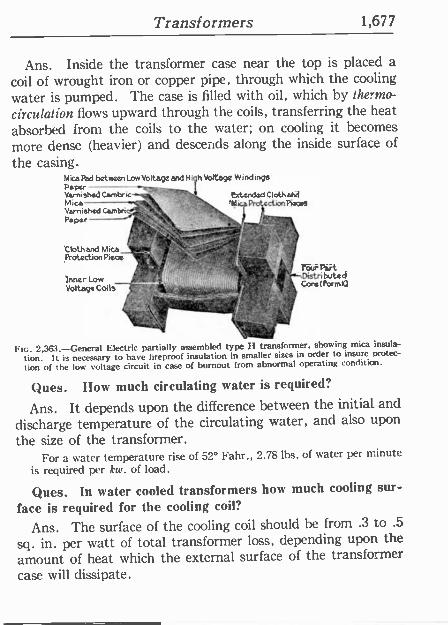
Transformers 1,677
Ans. Inside the transformer case near the top is placed a
coil of wrought iron or copper pipe, through which the cooling
water is pumped. The case is filled with oil, which by the~nto-
circulation flows upward through the coils, transferring the heat absorbed from the coils to the water; on cooling it becomes more dense (heavier) and descends along the inside surface of
the casing. Mica Pad between Low Voltage and High Voltage Windirx,7s Paper Varnished Cambric' extended ClothaM Mice PectionPieces Varnished CamDn . r Paper V
rl tTz,
Cloth and Mica Protection Piece
- (n rr
Inner Low Voltage Coils'
FIG. 2,363. General Electric partially assembled H transformer, showing mica insula-
tion. It is necessary to have fireproof insulation in smaller sizes in order to insure protec-
lion of the low voltage circuit in case of burnout from abnormal operating condition.
Ques. Ilow much circulating water is required?
Ans. It depends upon the difference between the initial and
discharge temperature of the circulating water, and also upon
the size of the transformer. For a water temperature rise of 52° Fahr., 2.78 lbs. of water per minute
is required per kw. of load.
Ques. In water cooled transformers how much cooling sur-
face is required for the cooling coil?
Ans. The surface of the cooling coil should be from .3 to .5
sq. in. per watt of total transformer loss, depending upon the
amount of heat which the external surface of the transformer case will dissipate.
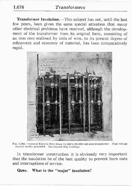
1,678 Transformers
Transformer Insulation.-This subject has not, until the last few years, been given the same special attention that many other electrical problems have received, although the develop- ment of the transformer from its original form, consisting of an iron core enclosed by coils of wire, to its present degree of refinement and economy of material, has been comparatively rapid.
r . ihenriometer Bulb Support
, T`1 Eye -Nutter - , ,- lndto Is
111 Barrier
Core Clomp- ing5tsd
bkfén,t r..9 ' - *IBnGg Locking Pin^ - _
Fm. 2,364.-General Electric three phase 13,200 to 66,000 volt auto transformer. High voltage neutral solidly grounded. Interleaved disc windings.
In transformer construction it is obviously very important that the insulation he of the best quality to prevent burn outs and interruptions of service.
Ques. What is the "major" insulation?
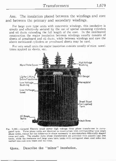
Transformers 1,679
Ans. The insulation placed between the windings and core and between the primary and secondary windings.
For large core type units ith concentric windings, this insulation is simply and effectively secured by the use of special insulating cylinders and oil ducts extending the full length of the core. In the interleaved construction the major insulation between windings usually consists of sheets of pressboard and oil ducts, while between windings and core the above mentioned cylinders or pressboard sheets may be used.
For very small units the major insulation consists usually of mica. some= times applied as sheets, etc.
r gZ: Hi hVolt ' e Hándifol¢Cover - - ;~Bushing,
"7r, , -1'.7c"rs7,Z^"4-^^' t
rp o 3 . h t
Lugfbr Lifting . .á+..c I- .. ` Oil Gauge`
tetire.Transform¢r.' t ,~ Low Voltage
s
1-NAmspata. Bushing >
Low Voltage a
Lead
Fáí
Sheet tteel 'corrugátoQ I Tarik
r .4-I I r..' I MQln'ilf
Valve Cff w " - 111 'Jack Boss,
Ftc. 2,365. -General Electric small power high voltage three phase transformer in corru- gated tank. Three phase tanks are identical in construction with corresponding type single phase tanks, except for the difference in shape necessary to accommodate differently shaped cores and coils. The smaller three phase transformers are provided with smooth cast iron tanks, while the moderate and large sizes have tanks with corrugated sheet steel sides cast welded into cast iron bases and to? rims.
Ques. Describe the "minor" insulation.
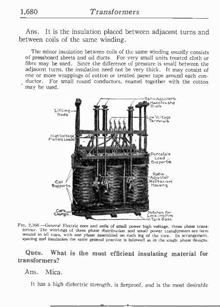
1,680 Transformers
Ans. It is the insulation placed between adjacent turns and between coils of the same winding.
The minor insulation between coils of the same winding usually consists of pressboard sheets and oil ducts. For very small units treated cloth or fibre may be used. Since the difference of pressure is small between the adjacent turns, the insulation need not be very thick. It may consist of one or more wrappings of cotton or treated paper tape around each con- ductor. For small round conductors, enamel together with the cotton may be used.
Ratio Adjusters. r Handles and
Dime Lifting' --'
Rods
í i . Ai 1-19hVoltage _'i.'i, p
a "
Flexible LeadS , r ,
il k
- 1^7'-r .Porceláin . . Lead
9':i..".. , .
l 1 , SuFportyl
r
Oil / :'- ` ,+:-' 8vpports ,=9.;'. ',' "_."y
-'~,
t l Ratio :' Adjuster M :Mechanisrn
lio,smq
t , L ` ;.,. ` p o`'`
Low Ve I tape Terminals
Core_ §u0 ^ t`IOtGhe3 í'Or Cramps.. _ Loca:mgyPins "m Tank lase
Fee. 2,366.-General Electric core and coils of small power high voltage, three phase trans- former. The windings of three phase distribution and small power transformers are form wound in all sizes, with one phase assembled on each leg of the core. In arrangement, spacing and insulation the same general practice is followed as in the single phase designs.
Ques. What is the most efficient insulating material for transformers?
Ans. Mica.
It has a high dielectric strength, is fireproof, and is the most desirable

Transformers 1,681
insulator where there are no sharp corners. Its use, however, is limited to small units, where it can be easily applied.
Oil Insulated Transformers.-High voltage transformers are insulated with oil, as it is very important to maintain careful insulation not only between the coils, but also between the coils and the core. In the case of high voltage transformers, any accidental static discharge, such as that due to lighting, which might destroy one of the air insulated type, might be success- fully withstood by one insulated . oil, for if the oil insulation be damaged
will mend itself at once. }. :5
:.
a '+:rr.. . 'E. P
M ''P' .'' 12-
' _ _ - *0.. -- -- .. _ . á' i J,K3 .
o - a --,+a0 -
-
'="41,1'. i em'-.,
4' °?;.
Fins. 2,367 and 2,368.-General Electric bushing construc- tion for distribution and small power transformers. Method of clamping porcelain bushings in transformer tank; fig. 2,363, cover bushing for moderately high volt- age distribution transformer.
By providing good circulation for the oil, the transformer can get rid of the heat produced in it readily and operate at a low temperature, which not only increases its life but cuts down the electric resistance of the copper conductors and therefore the I2R loss.
An important development in the construction of oil insulated trans- formers is the oil conservator, as shown in fig. 2,369. In this construction
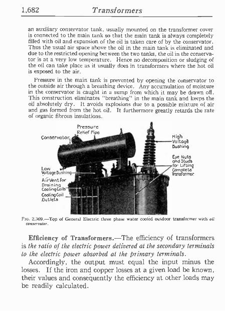
1,682 Transformers
an auxiliary conservator tank, usually mounted on the transformer cover is connected to the main tank so that the main tank is always completely filled with oil and expansion of the oil is taken care of by the conservator. Thus the usual air space above the oil in the main tank is eliminated and due to the restricted opening between the two tanks, the oil in the conserva- tor is at a very low temperature. Hence no decomposition or sludging of the oil can take place as it usually does in transformers where the hot oil is exposed to the air.
Pressure in the main tank is prevented by opening the conservator to the outside air through a breathing device. Any accumulation of moisture in the conservator is caught in a sump from which it may be drawn off. This construction eliminates "breathing" in the main tank and keeps the oil absolutely dry. It avoids explosions due to a possible mixture of air and gas formed from the hot oil. It furthermore greatly retards the rate of organic fibrous insulations.
Pressure Relief Pipe,,
Conservator
LOW .{f o }. BUShing-1. a.
AirVentfor Draining Cool inq Coils` Cooling Coil Outlets
i
E-
nigh Voltaga Bushing
Eye Nuts and Studs for Lifting Complete Transformer
-- 1 - '} FIG. 2,369.-Top of General Electric three phase water cooled outdoor transformer with oil
conservator.
Efficiency of Transformers.-The efficiency of transformers is the ratio of the electric power delivered at the secondary terminals to the electric power absorbed at the primary terminals.
Accordingly, the output must equal the input minus the losses. If the iron and copper losses at a given load be known, their values and consequently the efficiency at other loads may he readily calculated.
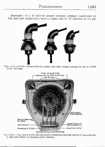
Transformers 1,683
Example.-If a 10 kilovolt ampere constant pressure transformer at full load and temperature have a copper loss of .21 kilowatt or 2.1 per
RP .
Fics. 2.370 to 2,372.-General Electric pocket type high voltage bushings for use on 19,250 to 551 volt lines.
'High Voltage Side Mechanically Held eushingS -
Set Screws
o{. `+i
.C2:vf , , :
yk
1
a;kat C¢artn urfac¢!
e P lace
Sit Screws }at
e ed IInto&Mu 7 Presaboard Collar ` Bushing Clamp
Mich6nicalitJ peid 8u1hIngo Flc. 2,373.-Top view of 2,300 volt distribution transformer showing location of core and coils
in tank and method of clamping pocket bushing.
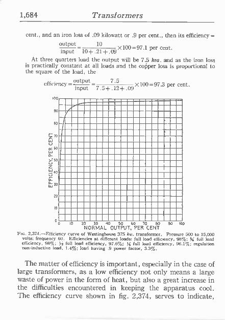
1,684 Transformers
cent., and an iron loss of .09 kilowatt or .9 per cent., then its efficiency =
output_ 10
input 10 --.21-x.09 X100 =97.1 per cent.
At three quarters load the output will he 7.5 kva. and as the iron loss is practically constant at all loads and the copper loss is proportional to the square of the load, the
efficiency =output 7.5 X100=97.3 per cent. input 7.5+.12+.09 100
90
80
Z 70
lil U 0= 60
20
t0
0 10 20 30 90 50 60 70 80 90 100 NORMAL OUTPUT, PER CENT
Ftc. 2,374.-Efficiency curve of Westinghouse 375 kw. transformer. Pressure 500 to 15,000 volts; frequency 60. Efficiencies at different loads: full load efficiency, 98%: 8já full load efficiency. 98%; 14 full load efficiency, 97.6%; to full load efficiency. 96.1%; regulation non -inductive load, 1.4%; load having .9 power factor. 3.3%.
The matter of efficiency is important, especially in the case of large transformers, as a low efficiency not only means a large waste of power in the form of heat, but also a great increase in the difficulties encountered in keeping the apparatus cool. The efficiency curve shown in fig. 2,374, serves to indicate,
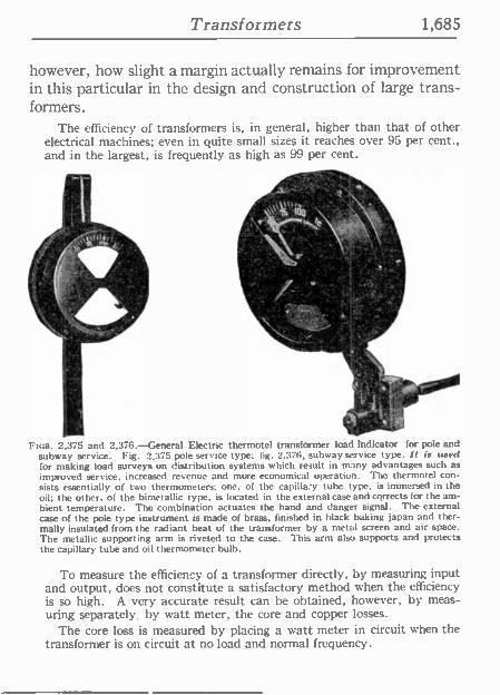
Transformers 1,685
however, how slight a margin actually remains for improvement in this particular in the design and construction of large trans- formers.
The efficiency of transformers is, in general, higher than that of other electrical machines; even in quite small sizes it reaches over 95 per cent., and in the largest, is frequently as high as 99 per cent.
I.
""'S11 .
.
FIGS. 2 375 and 2,376. -General Electric thermotel transformer load indicator for pole and subway service. Fig. 2,375 pole service type; fig. 2.376, subway service type. It is used for making load surveys on distribution systems which result in many advantages such as
improved service, increased revenue and more economical operation. The thermotel con- sists essentially of two thermometers; one, of the capillary tube type, is immersed in the oil; the other, of the bimetallic type, is located in the external case and corrects for the am- bient temperature. The combination actuates the hand and danger signal. The external case of the pole type instrument is made of brass, finished in black baking japan and ther- mally insulated from the radiant heat of the transformer by a metal screen and air space. The metallic supporting arm is riveted to the case. This arm also supborts and protects the capillary tube and oil thermometer bulb.
To measure the efficiency of a transformer directly, by measuring input and output, does not constitute a satisfactory method when the efficiency is so high. A very accurate result can be obtained, however, by meas- uring separately, by watt meter, the core and copper losses.
The core loss is measured by placing a watt meter in circuit when the transformer is on circuit at no load and normal frequency.
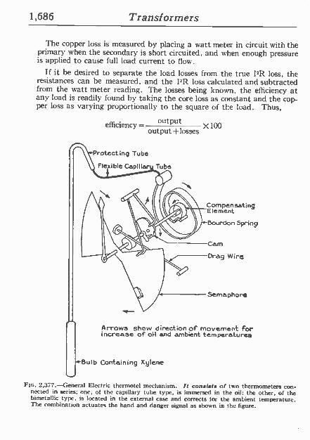
1,686 Transformers
The copper loss is measured by placing a watt meter in circuit with the primary when the secondary is short circuited, and when enough pressure is applied to cause full load current to flow.
If it he desired to separate the load losses from the true I2R loss, the resistances can be measured, and the I"R loss calculated and subtracted from the watt meter reading. The losses being known, the efficiency at any load is readily found by taking the core loss as constant and the cop- per loss as varying proportionally to the square of the load. Thus,
efficiency - output X 100 output +losses
Protecting Tube
Flexible Capiller Tube
Compensating Element
j-Dourdon Spring
Cam
Drag Wire
Semaphore
Arrows show direction of movement for increase of oil and ambient temperatures
+Bulb Containing Xylene
F[c. 2,377.-General Electric thermotel mechanism. /t consists of two thermometers con- nected in series; one, of the capillary tube type, is immersed in the oil; the other, of the bimetallic type, is located in the external case and corrects for the ambient temperature. The combination actuates the hand and danger signal as shown in the figure.
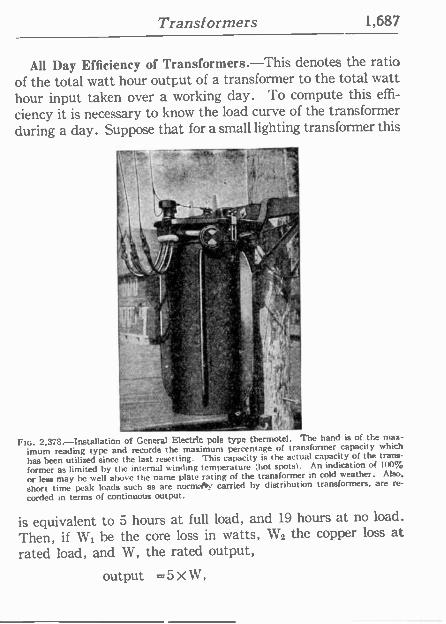
Transformers 1,687
All Day Efficiency of Transformers.-This denotes the ratio of the total watt hour output of a transformer to the total watt hour input taken over a working day. To compute this effi-
ciency it is necessary to know the load curve of the transformer during a day. Suppose that for a small lighting transformer this
a.K,--.- 4, t¡: t- 1
V .
l,, '' n
r
FIG. 2.378.-Installation of General Electric pole type thermotel. The hand is of the max-
imum reading type and records the maximum percentage of transformer capacity which
has been utilized since the last resetting. This capacity is the actual capacity of the trans-
former as limited by the internal winding temperature (hot spots). An indication of 100%
or less may be well above the name plate rating of the transformer in cold weather. Also.
short tinte peak loads such as are norm:hy carried by distribution transformers, are re-
corded in terms of continuous output.
is equivalent to 5 hours at full load, and 19 hours at no load.
Then, if W1 be the core loss in watts, W2 the copper loss at rated load, and W, the rated output,
output =5 X W,
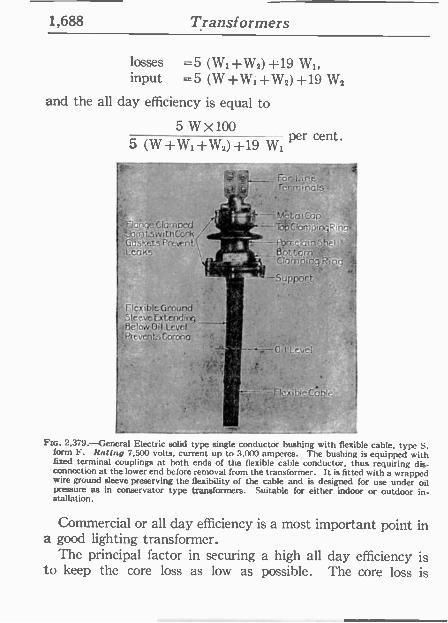
1,688 Transformers
losses =5 (WI +W2)+19 WI, input =5 (W+Wi+W2)+19 W2
and the all day efficiency is equal to
5 W X 100 per cent. 5 (W+W1+W2)+19 Wt
--- WO Liné Terminals
Flóhqe Clamped 'JaintswrthCork s ti tsnt5-f ,Porcelain5fiell'eoRsf3pttom
Ctarnpjng i2incj ; . N
Support
Flexible Ground ,.1.1."
Sleeve Extending Below Oil Level PreventsCorona ' ' .
---=0i12L'cve
Métal p Top lam ina
F[t:. 2.379. --General Electric solid type single conductor bushing with flexible cable, type S, form F. Rating 7,500 volts, current up to 3,000 amperes. The bushing is equipped with fixed terminal couplings at both ends of the flexible cable conductor, thus requiring dis- connection at the lower end before removal from the transformer. It is fitted with a wrapped wire ground sleeve preserving the flexibility of the cable and is designed for use under oil pressure as in conservator type transformers. Suitable for either indoor or outdoor in- stallation.
Commercial or all day efficiency is a most important point in a good lighting transformer.
The principal factor in securing a high all day efficiency is to keep the core loss as low as possible. The core loss is
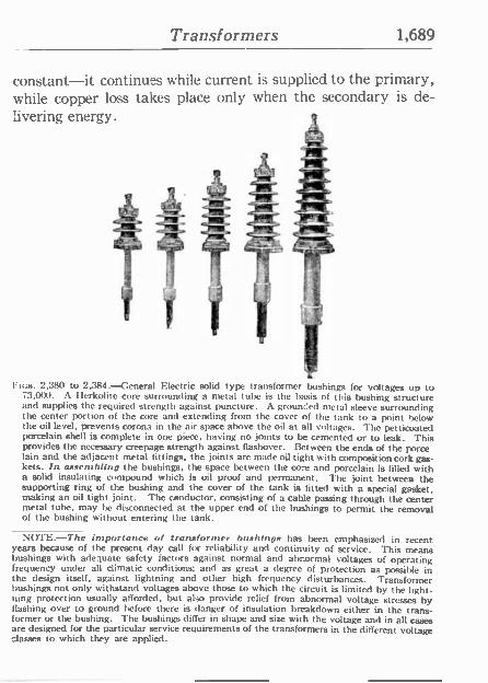
Transformers 1,689
constant-it continues while current is supplied to the primary, while copper loss takes place only when the secondary is de- livering energy.
o
Rtes. 2,380 to 2,384. -general Electric solid type transformer bushings for voltages up to 73,000. A Flerkolite core surrounding a metal tube is the basis of this hushing structure and supplies the required strength against puncture. A grounced metal sleeve surrounding the center portion of the core and extending from the cover of the tank to a point below the oil level, prevents corona in the air space above the oil at all voltages. Tie petticoated porcelain shell is complete in one piece, having no joints to be cemented or to leak. This provides the necessary creepage strength against flashover. Between the ends of the porce lain and the adjacent metal fittings, the joints are made oil tight with composition cork gas- kets. In assembling the bushings, the space between the co -e and porcelain is filled with a solid insulating compound which is oil proof and permanent. The joint between the supporting ring of the bushing and the cover of the tank is fitted with a special gasket, making an oil tight joint. The conductor, consisting of a cable passing through the center metal tube, may be disconnected at the upper end of the bushings to permit the removal of the bushing without entering the tank.
NOTE-The impurlance of traneformer bushings has been emphasized in recent years because of the present day call for reliability and continuity of service. This means bushings with adequate safety factors against normal and abnormal voltages of operating frequency under all climatic conditions; and as great a degree of protection as possible in the design itself, against lightning and other high frequency disturbances. Transformer bushings not only withstand voltages above those to which the circuit is limited by the light- ning protection usually afforded, but also provide relief from abnormal voltage stresses by flashing over to ground before there is danger of insulation breakdown either in the trans- former or the bushing. The bushings differ in shape and size with the voltage and in all cases are designed for the particular service requirements of the transformers in the different voltage classes to which they are applied.
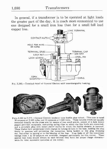
1,690 Transformers
In general, if a transformer is to be operated at light loads the greater part of the day, it is much more economical to use one designed for a small iron loss than for a small full load copper loss. _ ,LINE TERMINAL
-
CONTACT NUTS
HOLE FOR WIRE OR CORD
TERMINAL STUD LOCK NUT
LOCK SCREW
CORK GASKETS-
TERMINAL CAP 250 AMP.
STEEL PIN
Ftc. 2,385.-Terminal detail of General Electric solid interchangeable bushing.
~ EW - p >
1., £._'1 L 1 \ '" ; 00;,~t, 1
5
.ri
, 1 -
,/` ''yy ,"--.
M% /_ . o' _.4 y. .
nos. 2.386 to 2,338.-General Electric insulator type fusible plug cutout. This type is rated 30 amperes at 2,500 volts; and 15 amperes at 3.500 volts. These cutouts which are usually mounted directly on the cross arm by means of two wood screws, consist of a dark brown glazed porcelain receptacle, containing spring clips to which the line leads are connected, and a porcelain plug with nickel plated blades on which the fusible element is fastened. These blades have projections which engage in locking devices in the base, holding the plug firmly in position and preventing the connection being broken or the plug dropping out, due either to jarring or to the blowing of the fuse. Fuse links of all the convenient ratings from 1 to 30 amperes are available, designed particularly for this cutout. These special (use links should always be used because they have the proper design character- istics for most successful operation of the cutout.
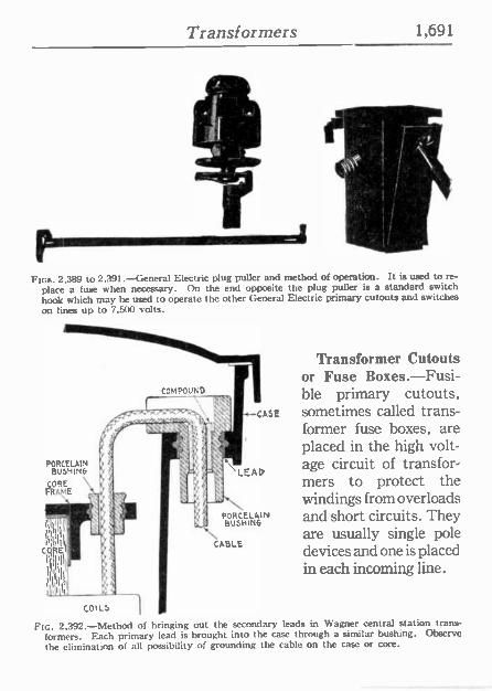
Transformers 1,691
t
FIGS. 2,389 to 2,391. --General Electric plug puller and method of operation. It is used to re-
place a fuse when necessary. On the end opposite the plug puller is a standard switch hook which may he used to operate the other General Electric primary cutouts and switches on lines up to 7.500 volts.
COMPOUND
PORCELAIN BUSHINfi
COILS
CABLE
Transformer Cutouts or Fuse Boxes.-Fusi- ble primary cutouts,
-case sometimes called trans- former fuse boxes, are placed in the high volt -
LEAD age circuit of transfor- mers to protect the windings from overloads
OR i AIN and short circuits. They BUNIG are usually single pole devices and one is placed. in each incoming line.
FIG. 2,392.-Method of bringing out the secondary leads in Wagner central station trans- formers. Each primary lead is brought into the case through a similar bushing. Observe
the elimination of all possibility of grounding the cable on the case or core.
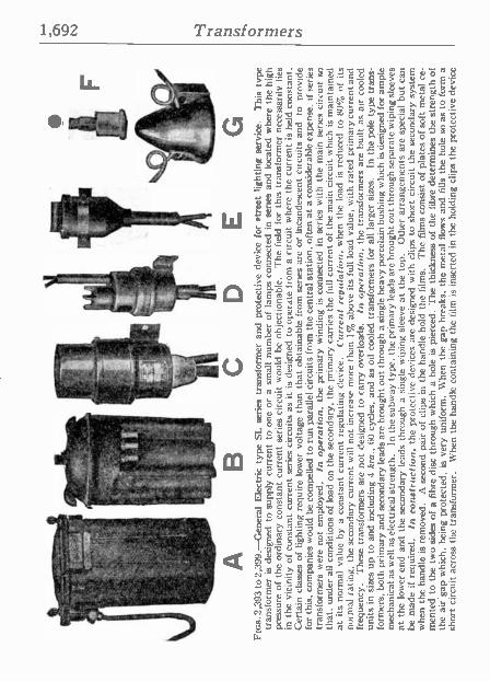
.
5 1,
rL
.
r
11
' -
J,
2-
'
L
1 1 .
. .
.'-
A
B
E
Fic
s.2,
393t
o2,3
99.-
Gen
eral
Ele
ctric
typ
e S
L se
ries
tran
sfor
mer
and
pr
otec
tive
devi
ce f
or
stre
et l
ight
ing
serv
ice.
T
his
type
tr
ansf
orm
er i
s de
sign
ed t
o su
pply
cur
rent
to
one
or
a sm
all
num
ber
of
lam
ps c
onne
cted
in
ser
ies
and
loca
ted
whe
re t
he h
igh
pres
sure
of
the
ordi
nary
con
stan
t cu
rren
t se
ries
circ
uit
wou
ld b
e ob
ject
iona
ble.
T
he f
ield
for
thi
s tr
ansf
orm
er n
eces
saril
y lie
s in
the
vi
cini
ty o
f co
nsta
nt c
urre
nt s
erie
s ci
rcui
ts a
s it
is d
esig
ned
to o
pera
te f
rom
a ci
rcui
t w
here
th
e cu
rren
t is
hel
d co
nsta
nt.
Cer
tain
cla
sses
of
light
ing
requ
ire
low
er v
olta
ge
than
th
at o
btai
nabl
e fr
om s
erie
s ar
c or
inc
ande
scen
t ci
rcui
ts a
nd
to
prov
ide
for
this
, co
mpa
nies
wou
ld b
e co
mpe
lled
to r
un p
aral
lel c
ircui
ts fr
om t
he c
entr
al s
tatio
n, o
ften
at a
con
side
rabl
e ex
pens
e. i
f se
ries
tran
sfor
mer
s w
ere
not
empl
oyed
. In
ope
ratio
n. t
he p
rimar
y w
indi
ng
is c
onne
cted
in
serie
s w
ith t
he
mai
n se
ries
circ
uit
so
that
, un
der
all
cond
ition
s of
load
on
the
seco
ndar
y, th
e pr
imar
y ca
rrie
s th
e fu
ll cu
rren
t of
the
mai
n ci
rcui
t w
hich
is
mai
ntai
ned
at it
s no
rmal
val
ue b
y a
cons
tant
cur
rent
reg
ulat
ing
devi
ce.
Cur
rent
reg
ulat
ion,
whe
n th
e lo
ad
is r
educ
ed
to 8
0% o
f its
no
rmal
rat
ing,
the
sec
onda
ry c
urre
nt w
ill n
ot in
crea
se m
ore
than
1%
abo
ve i
ts f
ull
load
val
ue,
with
rat
ed p
rimar
y cu
rren
t and
fr
eque
ncy.
T
hese
tra
nsfo
rmer
s ar
e no
t de
sign
ed t
o ca
rry
over
load
s.
In o
pera
tion,
the
tra
nsfo
rmer
s ar
e bu
ilt a
s ai
r co
oled
un
its i
n si
zes
up t
o an
d in
clud
ing
4 kr
a.,
60 c
ycle
s, a
nd a
s oi
l co
oled
tra
nsfo
rmer
s fo
r al
l la
rger
siz
es.
In t
he p
ole
type
tra
ns-
form
ers,
bot
h pr
imar
y an
d se
cond
ary
lead
s ar
e br
ough
t ou
t th
roug
h a
sing
le h
eavy
por
cela
in b
ushi
ng w
hich
is
desi
gned
for
am
ple
mec
hani
cal a
s w
ell
as e
lect
rical
str
engt
h.
In th
e su
bway
typ
e. t
he p
rimar
y le
ads
are
brou
ght
out
thro
ugh
sepa
rate
wip
ing
slee
ves
at t
he l
ower
end
and
the
sec
onda
ry l
eads
thr
ough
a
sing
le w
ipin
g sl
eeve
at
the
top.
O
ther
arr
ange
men
ts a
re s
peci
al b
ut c
an
be m
ade
if re
quire
d.
In c
onst
ruct
ion,
the
pr
otec
tive
devi
ces
are
desi
gned
with
clip
s to
sho
rt c
ircui
t th
e se
cond
ary
syst
em
whe
n th
e ha
ndle
is
rem
oved
. A
sec
ond
pair
of c
lips
in t
he h
andl
e ho
ld t
he f
ilms.
T
he f
ilms
cons
ist
of p
late
s of
sof
t m
etal
ce-
m
ente
d to
the
two
side
s of
a f
ibre
dis
c th
roug
h w
hich
a
hole
is
pier
ced.
T
he t
hick
ness
of
the
fibre
det
erm
ines
the
str
engt
h of
th
e ai
rgap
whi
ch,
bein
g pr
otec
ted,
is
very
uni
form
. W
hen
the
gap
brea
ks,
the
met
al f
low
s an
d fil
ls t
he h
ole
so
as to
for
m a
sh
ort
circ
uit
acro
ss t
he t
rans
form
er.
Whe
n th
e ha
ndle
con
tain
ing
the
film
is
inse
rted
in
the
hold
ing
clip
s th
e pr
otec
tive
devi
ce
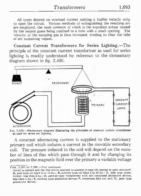
Transformers 1,693
All types depend on overload current melting a fusible metallic strip to open the circuit. Various methods of extinguishing the resulting arc arc employed, the most common of which is the expulsion action caused by the heated gases being confined in a tube with a small opening. The velocity of the escaping gas is thus increased, tending to clear the tube of arc sustaining vapors.
Constant Current Transformers for Series Lighting.-The principle of the constant current transformer as used for series lighting is readily understood by reference to the elementary diagram shown in fig. 2,400.
WEIGHT SECONDARY
X X CONSTANT
X CURRENT X LAMPS
X X
X,
FIG. 2,400.-Elementary diagram illustrating the principles of constant current transformer as used for series arc lighting.
A constant alternating current is supplied to the stationary primary coil which induces a current in the movable secondary coil. The pressure induced in the coil will depend on the num- ber of lines of flux which pass through it and by changing its position in the magnetic field over the primary a variable voltage
Ems. 2,393 to 2,399.-Text continued. circuit is opened and the film left in position to operate in case the system is open circuited. A, pole type oil filled 5 to 10 kw.; B, subway type oil filled 5 to 10 kw.; C, pole type trans- former. less than 5 kw.; D, subway type transformer with self contained protective device, less than 5 kw.; E, subway type protective device; F, automatic film cut out; G, pole type protective device.
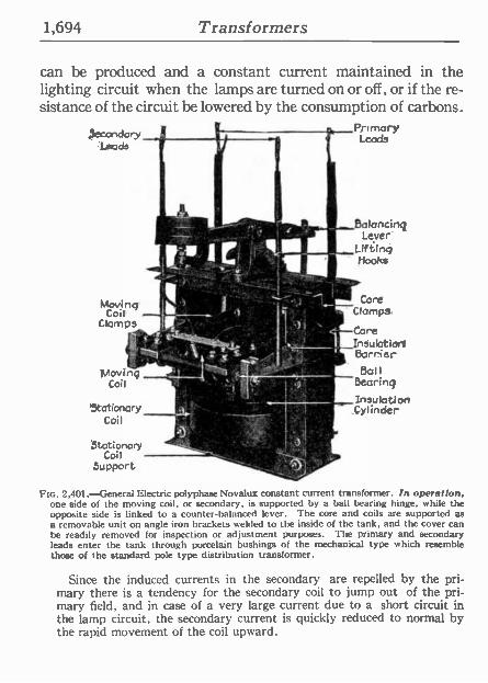
1,694 Transformers
can be produced and a constant current maintained in the lighting circuit when the lamps are turned on or off, or if the re- sistance of the circuit be lowered by the consumption of carbons.
da pnmary dsry
leads
; ;: 1q -`i°.p,..
Moving 9
Coil - Clomps
t _
: 1Novinq
Coil \
stationary Coil
Stationary Coil
Support
] fi: í r.
1
Balancing Lever
_Lifting - Hooka
:' Core ' - f Lo Clampl.
Core I a
' I. Insulotiorl ... ?,y - ' Barrer it.,- Bol l
Bearing __t_-__ Insulation
' _Cylinder
Ftc. 2,401.-General Electric polyphase Novalux constant current transformer. In operation, one side of the moving coil, or secondary, is supported by a ball bearing hinge, while the opposite side is linked to a counter -balanced lever. The core and coils are supported as a removable unit on angle iron brackets welded to the inside of the tank, and the cover can be readily removed for inspection or adjustment purposes. The primary and secondary leads enter the tank through porcelain bushings of the mechanical type which resemble those of the standard pole type distribution transformer.
Since the induced currents in the secondary are repelled by the pri- mary there is a tendency for the secondary coil to jump out of the pri- mary field, and in case of a very large current due to a short circuit in the lamp circuit, the secondary current is quickly reduced to normal by the rapid movement of the coil upward.
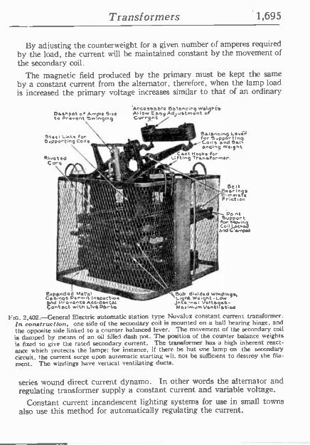
Transformers 1,695
By adjusting the counterweight for a given number of amperes required by the load, the current will be maintained constant by the movement of the secondary coil.
The magnetic field produced by the primary must be kept the same by a constant current from the alternator, therefore, when the lamp load is increased the primary voltage increases similar to that of an ordinary
Dashpot o Am la 5.eº to orovent wñ 9ing
Steal Links for Eopporting Cells
Riveted Cora
.'pond ed Metal " Casings Permit lnspect.o and Prevents Accidental Contact with Livp Parts
"ACCO»able ealaneinq woloQnts Allow Easy Adjustment of Crrr5nt i
' o . Balancing Lavºr, 5auppencd
Brtinelg
; fCe,l- ancing waignt Cast Hooks for
Li tln9 Transformar,
Ban oarin a
El.mnsfe Friction
Po nt pMving
Cooil t.oOckad
nd Vamped
/ lSlt$
»c ..
' óub divided wMdings, L ,jnte-nai Voltagqas-.ghR
Weight -Low
Maaimum Vantltatioa
Fic. 2,402.-General Electric automatic station type Novalux constant current transformer. In construction, one side of the secondary coil is mounted on a ball bearing hinge, and the opposite side linked to a counter balanced lever. The movement of the secondary coil is damped by means of an oil filled dash pot. The position of the counter balance weights is fixed to give the rated secondary current. The transformer has a high inherent react- ance which protects the lampe: for instance, if there be but one lamp on the secondary circuit, the current surge upon automatic starting wit. not be sufficient to destroy the fila- ment. The windings have vertical ventilating ducts.
series wound direct current dynamo. In other words the alternator and regulating transformer supply a constant current and variable voltage.
Constant current incandescent lighting systems for use in small towns also use this method for automatically regulating the current.
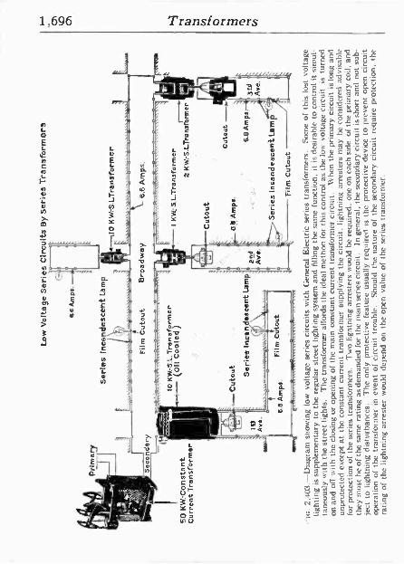
1,696 Transformers
Y N
Ú
u
n. »
m E E
iii1 .
o o « E o.. 3
u :11",:\= g m ' e. V u E o c
0 N I I _..0" ó
I I N0 ; .
m I I;" p N
Y) Y j
u
77,-
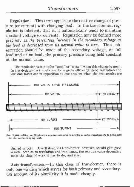
Transformers 1,697
Regulation.-This term applies to the relative change of pres- sure (or current) with changing load. In the transformer, reg- ulation is inherent, that is, it automatically tends to maintain constant voltage (or current) . Regulation may be defined more precisely as the percentage increase in the secondary voltage as the load is decreased from its normal value to zero. Thus, ob- servation should be made of the secondary voltage, at full load and at no load, the primary pressure being held constant at the normal value.
The regulation is said to be "good" or "close," when this change is small. In the design of a transformer for a given efficiency, good regulation and low iron losses are in opposition to one another when the best results are
t t00 VOLTS LINE PRESSURE
< 80 VOLTS 20 VOLTS->
_
-
BO TURNS
100 TURNS
14 2OTURNS--
Fm. 2,404.-Diagram illustrating connections and principles of auto -transformers as explained in the accompanying text.
desired in both. A well designed transformer, however, should gi-:e good results, both as to regulation and iron losses, the relative value depending upon the class of work it has to do, and size.
Auto-transformers.-In this class of transformer, there is
only one winding which serves for both primary and secondary. On account of its simplicity it is made cheaply.
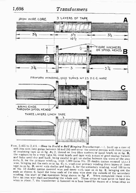
1,698 Transformers
ARON WIRE CORE 3 LAYERS OF TAPE
16RE WASHERS 3- = OR SPOOL HEADS B
PRIMARY WINDING, 1,000 TURNS N4 23 D.C.C. WIRE \ 111111%,
£'.. di' , !my 7i 11 N s I - . -_
BRING ENDS THROUGH SPOOL HEADS
THREE LAYERS LINEN TAPE
Fras. 2,405 to 2,411.-//nro to Re i d o hell Ringing Tr.'. stop -mgr. -1. build up a core of soft iron wire (any gauge between 16 and 24) and cover the central portion with three layers of insulating tape as in fig. A; 2, thread on two fibre washers a' spool heads as in fig. B, the washers to be a very tight fit; treat heads and tape with a coat of good shellac varnish and bake until dry and hard, being careful to get no shellac between the wires of the core ends; 3, for the primary winding, wind 1,000 turns No. 23 double cotton covered (d.c.c.) wire, bringing out the ends as in fig. C; 4. wind over primary winding three layers of linen tape as in fig. D, corer with shellac and bake; 5. for the secondary winding, wind 100 turns of No. 13 double cotton covered wire and cover with tape as in fig. E, bringing out the ends as shown; 6, bend the loose ends of the core wire over the outside of the secondary winding, the start of this operation being shown in fig. F. When completed these wires form an iron wire shell surrounding the whole coil. Three strips of tape serve to bind the wires in place; 7, the transformer is fastened to a base board by means of a brass strap as
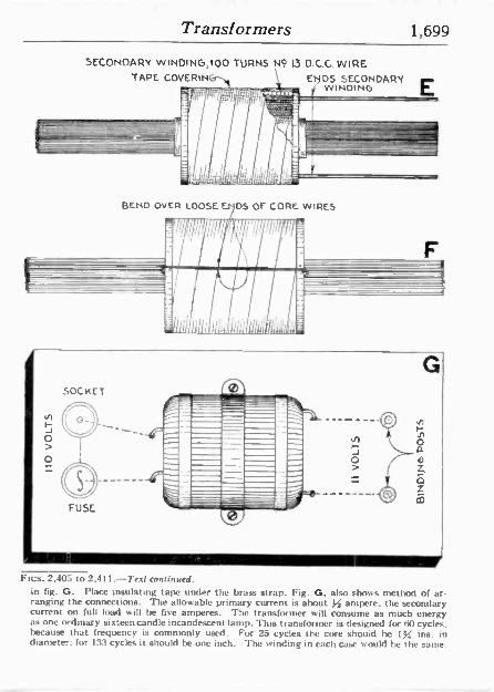
Transformers 1,699
SECONDARY WINOING,100 TURNS N4 13 D.G.G. WIRE TAPE COVERIN \ ENDS SECONDARY
WINDING
BEND OVER LOOSE E. DS OF CORE. WIRES
1111111.
J o >
G
Fics. 2,405 to 2,411.-Text continued. in fig. G. Place Insulating tape under the brass strap. Fig. G, also shows method of ar- ranging the connections. The allowable primary current is about ampere, the secondary current on full load will be five amperes. The transformer will consume as much energy as one ordinary si xteen candle incandescent lamp. This transformer is designed for 60 cycles. because that frequency is commonly used. For 25 cycles the core shouid he ljZ ins. in diameter: for 133 cycles it should be one inch. The winding in each case would he the same.
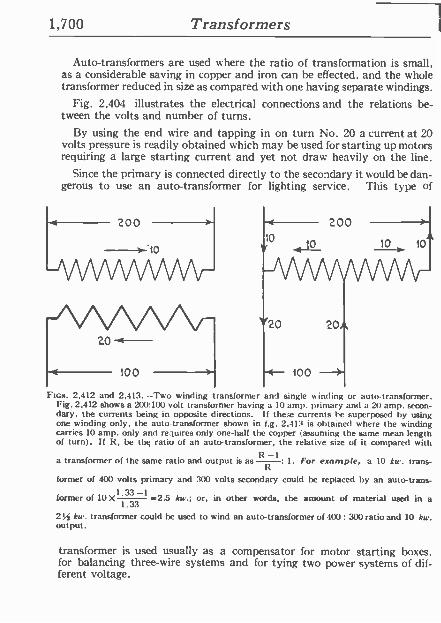
1,700 Transformers
Auto -transformers are used where the ratio of transformation is small, as a considerable saving in copper and iron can be effected, and the whole transformer reduced in size as compared with one having separate windings.
Fig. 2,404 illustrates the electrical connections and the relations be- tween the volts and number of turns.
By using the end wire and tapping in on turn No. 20 a current at 20 volts pressure is readily obtained which may be used for starting up motors requiring a large starting current and yet not draw heavily on the line.
Since the primary is connected directly to the secondary it would bedan- gerous to use an auto -transformer for lighting service. This type of
200
0 10 10 10
FIGS. 2,412 and 2,413.-Two winding ransformer and single winding or auto -transformer. Fig. 2,412 shows a 200:1(X) volt transformer having a 10 amp. primary and a 20 amp. secon- dary, the currents being in opposite directions. If these currents be superposed by using one winding only, the auto -transformer shown in t.g. 2,41:4 is obtained where the winding carries 10 amp. only and requires only one-half the copper(assuming the same mean length of turn). If It, be thq ratio of an auto -transformer, the relative size of it compared with
a transformer of the same ratio and output is as Ií1 1 : 1. For example, a 10 kw. trans-
former of 400 volts primary and 300 volts secondary could be replaced by an auto trans-
former of 10X1.33 -1 -2.5 kw.; or, in other words, the amount of material used in a 1.33
2 34 kw. transformer could be used to wind an auto -transformer of 400: 300 ratio and 10 kw. output.
transformer is used usually as a compensator for motor starting boxes, for balancing three -wire systems and for tying two power systems of dif- ferent voltage.
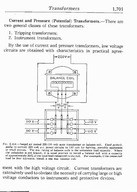
Transformers 1,701
Current and Pressure (Potential) Transformers.-There are two general classes of these transformers:
1. Tripping transformers; 2. Instrument transformers.
By the use of current and pressure transformers, low voltage circuits are obtained with characteristics in practical agree-
zz0 - -j
BALANCE. COIL
o
HO V 10
110 V 110
v
V
2,414 -Sorgel air cooled 220-110 volt auto transformer or balance coil. Used princi- pally to convert 220 volt a.c. power circuits to 110 volt for lighting, portable appliances or small motors. The kva. rating of balance coils is the unbalance load capacity. Where the unbalance is not known, it is usual practice to install a balance coil with a capacity of approximately 25% of the total load connected to the coil. For example, if the connected load be four kilowatts, install a one koa. balance coil.
ment with the high voltage circuit. Current transformers are extensively used to obviate the necessity of carrying large or high voltage conductors to instruments and protective devices.
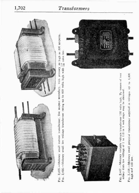
1,702 Transformers
i . r-: .... . r
-
I;
_ ot A ^.t--: t
' -iP: esi
f`1.p}q
V U L w` w
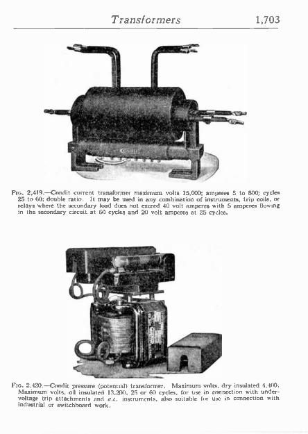
Transformers 1,703
111:
tit
;,1',.' - p f;'
,
.
.. ' R
''''.«.:.._, `;u- -J
Ftc. 2,419.-Condit current transformer maximum volts 15,000; amperes 5 to 800; cycles 25 to 60; double ratio. It may be used in any combination of instruments, trip coils, or relays where the secondary load does not exceed 40 volt amperes with 5 amperes flowing in the secondary circuit at 60 cycles and 20 volt amperes at 25 cycles.
It'. .7.1.1
c' r1.
. - gyp
M _IYi `i ' ., -may
y,`l " 1.. 1 ,,``' -
FIG. 2,420.-Condit pressure (potential) transformer. Maximum volts, dry insulated 4,400. Maximum volts, oil insulated 13.2;00. 25 or 60 cycles, for use in connection with under - voltage trip attachments and a.c. instruments. also suitable for use in connection with industrial or switchboard work.
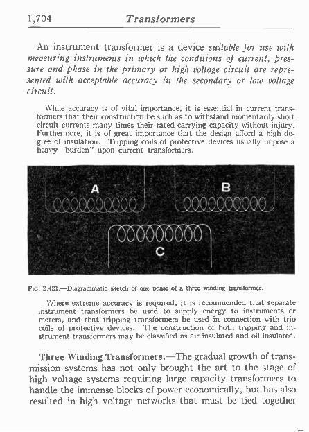
1,704 Transformers
An instrument transformer is a device suitable for use with measuring instruments in which the conditions of current, pres- sure and phase in the primary or high voltage circuit are repre- sented with acceptable accuracy in the secondary or low voltage circuit.
While accuracy is of vital importance, it is essential in current trans- formers that their construction be such as to withstand momentarily short circuit currents many times their rated carrying capacity without injury. Furthermore, it is of great importance that the design afford a high de- gree of insulation. Tripping coils of protective devices usually impose a heavy "burden" upon current transformers.
2,421.-Diagrammatic sketch of one phase of a three winding transformer.
Where extreme accuracy is required, it is recommended that separate instrument transformers be used to supply energy to instruments or meters, and that tripping transformers be used in connection with trip coils of protective devices. The construction of both tripping and in- strument transformers may be classified as air insulated and oil insulated.
Three Winding Transformers.-The gradual growth of trans- mission systems has not only brought the art to the stage of high voltage systems requiring large capacity transformers to handle the immense blocks of power economically, but has also resulted in high voltage networks that must be tied together
Transformers 1,705
in order that power may be interchanged between them. In some cases three sections, operating at different voltages, are tied together by means of one bank of transformers. This re- quires three winding transformers so designed that power may flow in any combination of ways between the three sections and not suffer prohibitive voltage regulation.
In practically all extensive high voltage systems of to -day, regulation of voltage at certain points is provided by means of synchronous con- densers. These condensers are connected to the high voltage system through transformers and in order to produce maximum economy in ap- paratus, in many cases the condenser connection is made through a third winding in the transformers, tying two sections of the system together.
The requirements of a transformer for this service are somewhat different from those where power may flow in various directions. hiere the react- ance between the condenser winding and the winding which feeds the sys- tem section from which the condenser draws its wattless power should be moderately low, so as to throw an excessive burden on the excitation range of the condenser. At the same time the reactance between it and the other two windings should be high enough to prevent excessively large short circuit currents in case of fault between the transformer and the condenser.
Another application of three winding transformers is where two sys- tems, or two sections of a system are to be tied together in such a manner that the phase positions of the two sections are identical and at the same time provide a neutral connection for the system, thus requiring star connection on both power windings. The third windings, in such cases, are connected in delta and are generally referred to as tertiaries.
Transformer Oil Dryer and Filter.-The deleterious effect of small amounts of moisture on the dielectric strength of oil is now well understood, and it appears to be even more serious than is generally supposed. In fig. 2,422, the curve shows clearly the great reduction in dielectric strength produced by the presence of water in very small amounts. As shown, the moisture content must not exceed .0008 per cent. (eight parts in 1,000,000) in order to obtain a dielectric strength of 22,000 volts in the standard test (.1 in. between the terminals) as required for all high tension work.
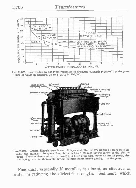
1,706 Transformers
35
ó 30 > O
25
20 W IS
Ñ U 10 ¢ w - 5 J W b
0
OIL IN GOOD COND TION
IL IN FAIR CONDITION
105K.V
I 0.1'GAP BETWEEN I"DISCS
I i i i
OIL IN THIS CLASS SHOULD BE IMMEDIATELY FILTERED OR REPLaCED (NE IA RULING)
2 3 4 5 6 7 8
WATER PARTS IN 100,000 BY VOLUME 9
FIG. 2,422.-Curve showing the great reduction in dielectric strength produced by the pres-
ence of water in amounts up to 8 parts in 100,000.
ótationery 3,,¡ Outlet r mho 8
Clempmg mita UnlOn \ i1p{;lYÍ;tA1a. 7ll}p° Moveblº Climpinq Praaaurn Gauge - - ' : JRN#N11It171¡(milll', .Plica
rlttlHn[nNlNpnt-) y _`+-ClOndqaemppnq
0
r.
llornon oks .1 U
Air B:N- '' ' 1 lld J ' 1 -Pulley F or 1í1 .' 'i ¡^
''',/''... L 5tit.arnat drive
istreinar. 14.1: i1 "' ' f .Gr 1
Pump_s.,.t P
ó yti (t r oo jj
,u.
FIG. 2,423. --General Electric transformer oil dryer and filter for freeing the oil from moisture,
slime and sediment. In operation, the oil is forced. through several layers of dry blotting paper. The complete equipment consists of a filter press with motor driven oil pump, elec-
tric drying oven for thoroughly drying the filter paper before placing it in the press.
rii
g., - ,Drip pin
.End FramQ
Fine dust, especially if metallic, is almost as effective as water in reducing the dielectric strength. Sediment, which
Transformers 1,707
may result from long continued heating, should also be re- moved in order to preserve the normal viscosity of the oil and to prevent accumulations on interior parts of the transformer and possible clogging of the oil channels.
An efficient method frees the oil from moisture, slime and sediment by forcing it under pressure through several layers of dry blotting paper in a specially designed filter press. The paper is free from chemicals, foreign substances and coloring matter, and is furnished cut to exact size to fit the filter. The solid matter in the oil is caught by the paper, while the water is retained by capillary action. The capillary attraction between the paper and water is greater than that between the paper and the oil and effective- ness of the method is mainly due to this fact. One treatment is generally sufficient to produce a dielectric strength of 28,000 volts, corresponding to a water content of only one part in about 250,000. A purity greater than this ís of no practical benefit as it cannot be maintained with the oil in regular use.
Effects of Operating Conditions on Transformer Perform- ance.-The effects due to changes in operating conditions as here given should he noted.
Effects of Change in Voltage Iron Loss. The iron loss varies approximately as the square of the voltage.
Copper Loss. The copper loss also varies as the square of the voltage, but decreases with an increase in voltage: assuming a constant kilovolt ampere output.
Efficiency. The efficiencies of distribution type transformers at fractional loads will de-
crease with an increase in voltage, whsle the efficiencies at full load or overloads will increase with an increase in voltage and vice versa.
Regulation. The regulation will vary as the square of the voltage, but will decrease with an increase in voltage, assuming a constant kilovolt ampere output.
The following table shows approximate variations in the performance of distributing trans- formers with variations in voltage assuming a constant output.
Iron Loss Copper Loss Regulation Voltage per cent. per cent. per cent.
2.200 91 109 109
2.300 100 100 100
2,400 109 91 91
Heating. Iron temperatures increase and copper temperatures decrease with an increase in voltage, and vice versa, for a constant kilovolt ampere output.
1,708 Transformers
Effects of Changes in Frequency Iron Loss. The iron loss will increase with a decrease in frequency. A 60 cycle trans-
former will have approximately 11% higher iron loss when operated at 50 cycles than at 60 cycles., The iron loss of a 60 cycle transformer operated on 25 cycles is so high as to make such a practice impossible. It is, however, possible to operate a 25 cycle unit on 60 cycles and in this case the iron loss will be decreased 25%.
Copper Loss. In distribution transformers the copper loss is practically independent of the frequency': .
Efficiency. Since the copper loss is not affected by a decrease in frequency, a given trans- former efficiency will be less at a low frequency than at a high one.
Regulation. The regulation at 100% power factor is not affected appreciably by a change in frequency since ohmic drop is independent of frequency. The reactance drop is so af- fected. however, and the regulation at low power factors will decrease with a decrease in frequency and vice versa. Thus the regulation of a 25 cycle transformer, when operated on 60 cycles and at low power factors, will be very much poorer than when operated at 25 cycles.
Heating. As the total loss is greater at a low frequency than at a high one, the temperature will be correspondingly increased
Effect of Changes in Wave Form Performance data is based upon operation on circuits having a pressure sine wave. A peaked wave will give lower values of iron loss, while a flat top wave will give higher values of
iron loss than those given in the tables, with corresponding Increase and decrease in efficiency. Copper loss and regulation are practically independent of wave form, while the heating is slightly less on circuits having a peaked wave and slightly greater on circuits having a flat wave than on those with a sine wave.
TEST QUESTIONS
1. What is a transformer? 2. State the basic principle on which transformers op-
erate. 3. What is the difference between a primary and sec-
ondary winding? 4. Upon what does the induced voltage depend? 5. When there is no load on the transformer, does any
current Jlow? 6. What is the difference between the magnetizing cur-
rent and the no load current?
Transformers 1,709
7. Describe the action of the transformer with. load.
8. Give a classification of transformers. 9. What is the difference between a step up and a step-
down transformer? 10. What is the difference between a core and snell trans-
former? 11. Describe a distributed core transformer. I2. Is it necessary to use a polyphase transformer to
transform a polyphase current? 13. Name two varieties of polyphase transformer. 14. What are the various transformer losses?
15. Define hysteresis. 16. On what does hysteresis depend? 17. What mode of construction is adapted to avoid eddy
ct rrents? 18. Why does a transformer take current when the sec-
ondary circuit is open?
19. Which are the more important, the iron or copper losses, and why?
20. How may the iron losses be reduced to a minimum?
21. Name some methods of cooling transformers.
22. What is the behavior of a transformer with respect to heating when operated continuously at full load?
23. Why is a high rise of temperature objectionable?
24. Describe a natural draught air cooled transformer.
25. How much air is ordinarily used for cooling per kw, of load?
26. Explain the circulation of oil in an oil cooled transformer.
1,710 Transformers
27. In what other capacities besides that of cooling agent, does the oil act?
28. What is an objection to oil? 29. How is a water cooled transformer cooled? 30. How much circulating water is required? 31. In water cooled transformers how much cooling sur-
face is required for the cooling coil? 32. What is the major and minor insulation? 33. What is the most efficient insulating material for
transformers? 34. Define the term -efficiency of transformers- and give
example. 35. How is a transformer efficiency curve constructed? 36. What is the all day efficiency of a transformer? 37. What are transformer bushings used for? 38. Describe a constant current transformer. 39. Define the term regulation. 40. What is an auto -transformer? 41. What is the difference between current and pressure
(potential) transformers? 42. Describe a three winding transformer. 43. How is oil treated for transformers?
Transformer Connections 1,711
CHAPTER 53
Transformer Connections Transformer Connections.-The alternating current has the
advantage over direct current, in the ease with which the pressure and current can be changed by different connections of transformers.
On single phase circuits the transformer connections can be varied to change current and pressure. and in addition on polyphase circuits the phases can also be changed to almost any form.
Single Phase Connections.-The method of connecting or- dinary distribution transformers to constant pressure mains is shown by the elementary diagram, fig. 2,426, where a transfor- mer of 10 to 1 ratio is indicated with its primary winding con- nected to a 1,000 volt main, and a secondary winding to deliver 100 volts.
Fig. 2,424 shows a transformer with each winding divided into two sections. Each primary section is wound for 1.000 volts, and each sec- ondary section for 50 volts. By connecting the entire primary winding in series, the transformer may be supplied from a 2,000 volt main, as indicated, and if the secondary winding he also connected all in series, as shown, the no load voltage will be 100 between the secondary terminals.
The sections of the primary winding may be connected in parallel to a 1,000 volt main, and 100 volts obtained from the secondary, or the primary and secondary windings may be connected each with its two sections in parallel, and transformations made from 1.000 to 50 volts as represented in fig. 2,425.
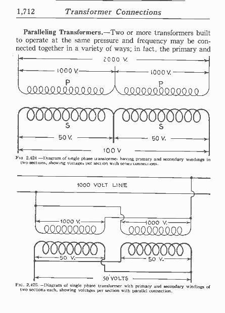
1,712 Transformer Connections
Paralleling Transformers.-Two or more transformers built to operate at the same pressure and frequency may he con- nected together in a variety of ways; in fact, the primary and
2000 v.
Too Flo. 2,424 -Diagram of single phase uansiorme, having primary and secondary windings in
two sections, showing voltages per section with series connections.
1000V.
1000 VOLT LINE
1000V.
Q9LO_CI4D4 Y =00 5o Y.
50 VOLTS >'
FIG. 2,425.-Diagram of single phase transformer with primary and secondary windings of two sections each, showing voltages per section with parallel connection.
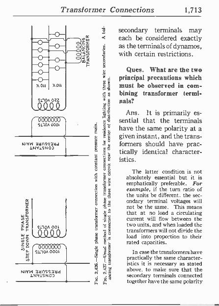
Transformer Connections 1,713
A 011 .A011
S11OA OZ2.
S110 0001
NIVW 311115S3ad 1NV1SN0)
ñ secondary terminals may W < each be considered exactly Z£
Z w as the terminals of dynamos, -JZ with certain restrictions. mI-
1 s Ques. What are the two
á principal precautions which
I. r must be observed in com- bining transformer termi-
g nals?
Ans. It is primarily es - 9 sential that the terminals
. have the same polarity at a 1
t given instant, and the trans - 1 ° t formers should have prac- É. 9..- tically identical character - í 1 = istics. ó O
The latter condition is not 3 g ` absolutely essential but it is
emphatically preferable. For º ro t example, if the turn ratio of 1 s the units be different. the sec -
1 r ondary terminal voltages will not be the same. This means
É º that at no load a circulating ° 1 current will flow between the
R5 c two units, and when loaded the
- E 5 transformers will not divide the load into proportion to their
É rated capacities.
y `$ In case the transformers have I I Á practically the same character-
istics it is necessary as stated c above. to make sure that the
N ,i.1
S11OA 001
NNW 3anss3dd 1NV1SN0D secondary terminals connected
w w together have the same polarity
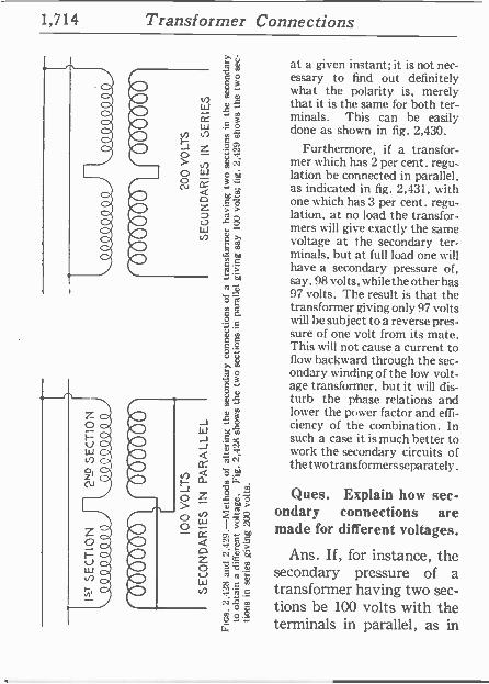
1,714 Transformer Connections
at a given instant; it is not nec- essary to find out definitely what the polarity is, merely that it is the same for both ter- minals. This can he easily done as shown in fig. 2,430.
Furthermore, if a transfor- mer which has 2 per cent. regu- lation be connected in parallel, as indicated in fig. 2,431, u ith one which has 3 per cent. regu- lation, at no load the transfor- mers will give exactly the same voltage at the secondary ter- minals, but at full load one will have a secondary pressure of, say, 98 volts, while the other has 97 volts. The result is that the transformer giving only 97 volts will he subject to a reverse pres- sure of one volt from its mate. This will not cause a current to flow backward through the sec- ondary winding of the low volt- age transformer, but it will dis- turb the phase relations and lower the power factor and effi- ciency of the combination. In such a case it is much better to work the secondary circuits of thetwotransformers separately.
Ques. Explain how sec- ondary connections are made for different voltages.
Ans. If, for instance, the secondary pressure of a transformer having two sec- tions be 100 volts with the terminals in parallel, as in

Transformer Connections 1,715
fig. 2,428, then connecting them in series will give 200 volts at the free secondary terminals, as indicated in fig. 2,429.
I'm. 2 430.-Method of comparing instantaneous polarities. Two of the terminals are con- nected as shown by a small strip of fuse wire, and then touching the other two terminals together. If the fuse blow, then the connections must be reversed; if ít do not, then they may be made permanent.
PRIMARY MAIN 1000 VOLTS
440044 "90009
$$##$$$ 100 VOLTS NO LOAD 98 " FULL
000000000001
O,,,,, IOC VOLTS NO LOAD 91 FULL "
SECONDARY MAIN
FIG. 2,431.-Diagram showing unlike single phase transformers in parallel.
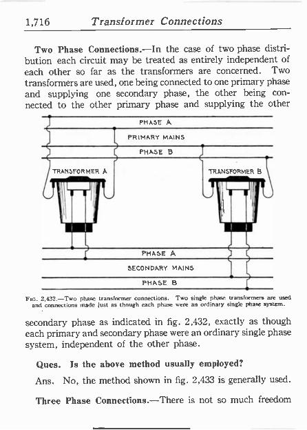
1,716 Transformer Connections
Two Phase Connections.-In the case of two phase distri- bution each circuit may be treated as entirely independent of each other so far as the transformers are concerned. Two transformers are used, one being connected to one primary phase and supplying one secondary phase, the other being con- nected to the other primary phase and supplying the other
PHASE A
PRIMARY MAINS
PHASE B
TRANSFORMER A
1
TRANSFORMER B
J 111
¡I
i
PHASE A
SECONDARY MAINS
PHASE B
FIG. 2,432.-Two phase transformer connections. Two single phase transformers are used and connections made just as though each phase were an ordinary single phase system.
secondary phase as indicated in fig. 2,432, exactly as though each primary and secondary phase were an ordinary single phase system, independent of the other phase.
Ques. Is the above method usually employed?
Ans. No, the method shown in fig. 2,433 is generally used.
Three Phase Connections.-There is not so much freedom
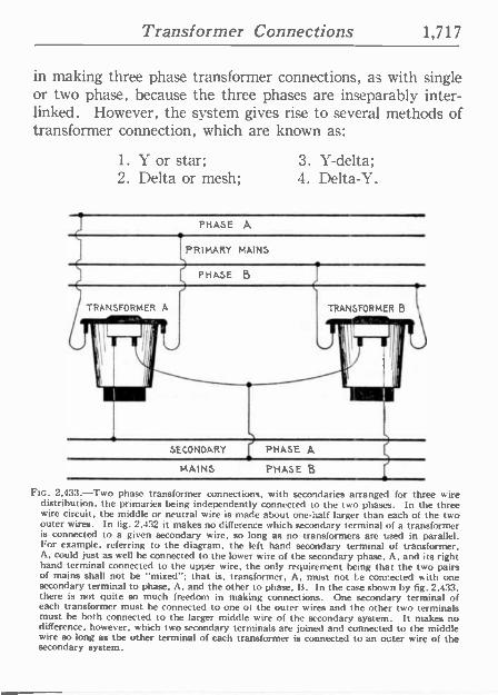
Transformer Connections 1,717
in making three phase transformer connections, as with single or two phase, because the three phases are inseparably inter - linked. However, the system gives rise to several methods of transformer connection, which are known as:
1. Y or star; 2. Delta or mesh;
3. Y -delta; 4. Delta -Y.
PHASE A
PRIMARY MAINS
PHASE B
TRANSFORMER A
J_ TRANSFORMER B
,
SECONDARY PHASE A
MAINS PHASE B
FIG. 2,433.-Two phase transformer connections, with secondaries arranged for three wire distribution, the primaries being independently connected to the two phases. In the three wire circuit, the middle or neutral wire is made about one-half larger than each of the two outer wires. In fig. 2,432 it makes no difference which secondary terminal of a transformer is connected to a given secondary wire, so long as no transformers are used in parallel. For example, referring to the diagram, the left hand secondary terminal of transformer, A, could just as well be connected to the lower wire of the secondary phase. A, and its right hand terminal connected to the upper wire, the only requirement being that the two pairs of mains shall not be "mixed"; that is, transformer, A, must not le connected with one secondary terminal to phase, A. and the other to phase, B. In the case shown by fig. 2.433. there is not quite so much freedom in making connections. One secondary terminal of each transformer must be connected to one of the outer wires and the other two terminals must be both connected to the larger middle wire of the secondary system. It makes no difference, however, which two secondary terminals are joined and connected to the middle wire so long as the other terminal of each transformer is connected to an outer wire of the secondary system.
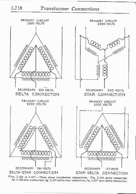
1,718 Transformer Connections
PRIMARY CIRCUIT 2200 VOLTS
SECONDARY 220 VOLTS
DELTA CON INECTION
PRIMARY CIRCUIT 2200 VOLTS
SECONDARY 381 VOLTS
DELTA -STAR CONNECTION
PRIMARY CIRCUIT 2200 VOLTS
SECONDARY 220 VOLTS
STAR CONNECTION
PRIMARY CIRCUIT 2200 VOLTS
0000
SECONDARY
STAR- DELTA 127 VOLTS
CONNECTION FIGS. 2,434 to 2,437.-Three phase transformer connections. Fig. 2.434 delta connection: fig. 2,435 star connection; tig. 2,436 delta -star connection; fig. 2,437 star -delta connection.

Transformer Connections 1,719
Delta Connection.-In the delta connection both primaries and sec- ondaries are connected in delta grouping, as in fig. 2,434.
Y Connect ion.-This method consists in connecting both the primaries and secondaries in star grouping, as in fig. 2,435.
Delta Y Connection.-In this method the primaries are connected in delta grouping and the secondaries in star grouping, as in fig. 2,436.
Ftc. 2.438.-Three wire connections for transformer having two secondary sections on different legs of the core. If the secondary terminals be connected up to a three wire distribution, as here shown diagrammatically, it is advisable to make the fuse 2, in the middle wire. considerably smaller than necessary to pass the normal load in either side of the circuit, because, should the fuse 1, be blown, the secondary circuit through the section Sa, will be open, and the corresponding half of the primary winding Pa. will have a much higher impedance than the half of the primary winding Ph. the inductance of which is so nearly neutralized by the load on the secondary winding St>. The result will be that the voltage of the primary section Pa, will be very much greater than that of the section Pb, and as
the sections are in series the current must he the same through both halves of the winding; the drop or difference of pressure, therefore, between the terminals of Pa, will be much higher than that between the terminals of Ph. consequently, the secondary voltage of Sh, will be greatly lowered and the service impaired. As the primary winding Pa, is designed
to take only one-half of the total voltage, the unbalancing referred to will subject it to a considerably higher pressure than the normal value; consequently, the magnetic density in that leg of the transformer core will be much higher than normal, and the transformer will heat disastrously. If the fuse 2. in the middle wire be made, say, one-half the capacity of each of the other fuses, this condition will be relieved by the blowing of this fuse, and as the lamps in the live circuit would not be anywhere near candle power if the circuit re- mained intact, the blowing of the middle fuse will not be any disadvantage to the user
of the lamps. Some makers avoid the contingency just described by dividing each sec-
ondary coil into two sections and connecting a section on one leg in series with a section on the other leg of the core, so that current applied to either pair of the secondary terminals will circulate about both legs of the core.
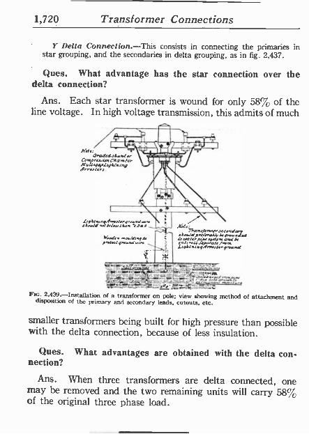
1,720 Transformer Connections
Y Delta Connection.-This consists in connecting the primaries in star grouping, and the secondaries in delta grouping, as in fig. 2,437.
Ques. What advantage has the star connection over the delta connection?
Ans. Each star transformer is wound for only 58% of the line voltage. In high voltage transmission, this admits of much
=a'i~11111 ~Nor Le7FiZ% ̀r3 Xa: J-. R - ~fed Ar s: o. Comp**. CAanler A r.l[rgap4yAln CoA
iny Arueera.
( 9Alnrnga of q.erd...e JeWd+.tdsl.u[Aun :p:a
Ned., w.osd.,qv pncst gror..0 ...
ó
Xr. h sAo../a
n p>.a+ e`cndy p.r aa/y 07.046,4'410 rnete>pays[em and d ( ents ^ ;e /.v .qA! wqA [.qro.nd
Fin. 2,439.-Installation of a transformer on pole; view showing method of attachment and disposition of the primary and secondary leads, cutouts, etc.
smaller transformers being built for high pressure than possible with the delta connection, because of less insulation.
Ques. What advantages are obtained with the delta con- nection?
Ans. When three transformers are delta connected, one may be removed and the two remaining units will carry 58% of the original three phase load.
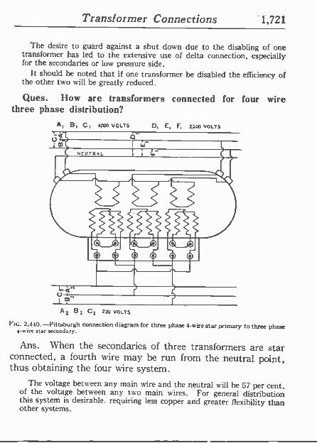
Transformer Connections 1,721
The desire to guard against a shut down due to the disabling of one transformer has led to the extensive use of delta connection, especially for the secondaries or low pressure side.
It should be noted that if one transformer be disabled the efficiency of the other two will be greatly reduced.
Ques. How are transformers connected for four wire three phase distribution?
A, B, C, 4poo vot.rs D, E, F, 230o VOLTS
c
U -4V
A 2 B Z C2 230 VOLTS
FIG. 2,440.-Pittsburgh connection diagram for three phase 4 -wire star primary to three phase 4 -wire star secondary.
Ans. When the secondaries of three transformers are star connected, a fourth wire may he run from the neutral point, thus obtaining the four wire system.
The voltage between any main wire and the neutral will be 57 per cent. of the voltage between any two main wires. For general distribution this system is desirable. requiring less copper and greater flexibility than other systems.
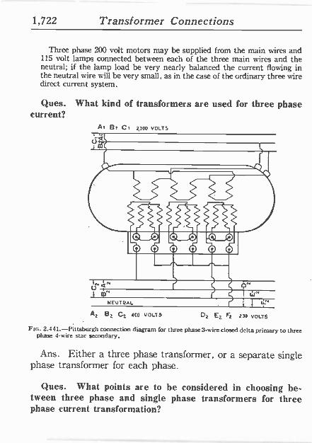
1,722 Transformer Connections
Three phase 200 volt motors may be supplied from the main wires and 115 volt lamps connected between each of the three main wires and the neutral; if the lamp load be very nearly balanced the current flowing in the neutral wire will be very small, as in the case of the ordinary three wire direct current system.
Ques. What kind of transformers are used for three phase current?
Ai Bt C, 2,aoo VOLTS
NEUTRAL
A¿ B1 CZ 4C0 VOLTS OZ E1 F5 230 VOLTS
Ftc. 2.441.-Pittsburgh connection diagram for three phase 3 -wire closed delta primary to three phase 4 -wire star secondary.
Ans. Either a three phase transformer, or a separate single phase transformer for each phase.
Ques. What points are to be considered in choosing be- tw een three phase and single phase transformers for three phase current transformation?
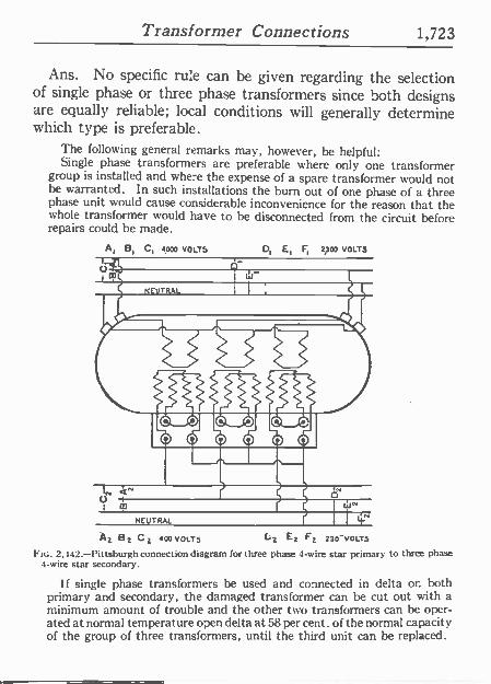
Transformer Connections 1,723
Ans. No specific rule can be given regarding the selection of single phase or three phase transformers since both designs are equally reliable; local conditions will generally determine which type is preferable.
The following general remarks may, however, be helpful: Single phase transformers are preferable where only one transformer
group is installed and where the expense of a spare transformer would not be warranted. In such installations the burn out of one phase of a three phase unit would cause considerable inconvenience for the reason that the whole transformer would have to be disconnected from the circuit before repairs could be made.
A, B, C, 4000 VOLTS D, E, F, 2300 VOLTS
O3
NEUTRAL 11_ A2 B2 C2 400 VOLTS 1.2 E2 F2 230 -VOLTS
FIG. 2,442.-Pittsburgh connection diagram for three phase 4 -wire star primary to three phase 4 -wire star secondary.
If single phase transformers be used and connected in delta or. both primary and secondary, the damaged transformer can be cut out with a minimum amount of trouble and the other two transformers can be oper- ated at normal temperature open delta at 58 per cent. of the normal capacity of the group of three transformers, until the third unit can be replaced.
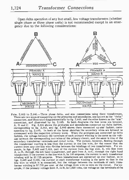
1,724 Transformer Connections
Open delta operation of any but small, low voltage transformers (whether single phase or three phase units) is not recommended except in an emer- gency due to the following considerations:
B
PRIMARY A
MAINS B
It V + ` IF n.a L[I
I 1 1 I!! SECONDARY
MAINS
1000
PRIMARY A
MAINS B
MAINS
C C
Fins. 2,443 to 2,446.-Three phase delta, and star connections using three transformers. There are two ways of connecting up the primaries and secondaries, one known as the "delta" connection, and illustrated diagrammatically by fig. 2,443. and the other known as the "star" connection, and illustrated by lig. 2,445. In both diagrams the line wires are lettered, A, B and C. Fig. 2,444 shows the primaries and secondaries connected up delta fashion, corresponding to fig. 2,443, and fig. 2,446 shows them connected up star fashion, corre- sponding to fig. 2,445. In both of the latter sketches the secondary wires are lettered to correspond with the respective primary wires. When the primaries are connected up delta fashion, the voltage between the terminals of each primary winding is the same as the volt- age between the corresponding two wires of the primary circuit, and the same is true of the secondary transformer terminals and circuit a ires. The current, however, flowing through the transformer winding is less than the current in the line wire, for the reason that the current from any one line wire divides between the windings of two transformers. For ex- ample, in figs. 2,443 and 2,444. part of the current from the line wire, A, will flow from A, to B. through the left hand transformer, and part from A, to C, through the right hand transformer; if the current in the line wire A, be 100 amperes, the current in each transformer winding will be 57.735 amperes. When transformers are connected up star fashion, as in figs. 2.445 and 2,446, the current in each transformer winding is the same as that in the line wire to which it is connected, but the voltage between the terminals of each trans- former winding is 57.735 per cent. of the voltage from w ire to wire on the circuit. For ex- ample, if the primary voltage from A, to B, be 1,000 volts, the voltage at the terminals of the
Transformer Connections 1,725
1. The internal power factor of the hank being only 86.6%, the active units or coils can deliver only 86.6% of their rated kva.;
2. An open delta bank is somewhat more liable to damage under ab- normal voltage disturbances than a closed delta bank;
Shell type. When necessary to operate a three phase shell type trans- former open delta, due to a damaged winding, care should be taken to see that both primary and secondary windings of the damaged phase are not only disconnected but also short circuited upon themselves, otherwise greater damage may result. By short circuiting the winnings the mag- netic flux in that section of the core is neutralized.
Core type. Three phase core type transformers can not be operated with two phases in open delta, unless the entire damaged phase be re- moved from the core or else every turn of the damaged coil is open cir- cuited and the series connection between the other coils broken. This is necessary because the damaged phase is subject to very high voltages and high frequencies and unless sectionalized so that lew turns are in series, serious damage may result. This is especially important when the voltage is greater than 44,000.
FIGS. 2,443 to 2,446.-Text continued.
left hand transformer (from A, to star point,) will be only 577.35 volts, an.l same is true of each of the other transformers if system be balanced. These statements apply, of course. to both primary and secondary windings, from which it will become evident that if the three transformers of a three phase circuit be connected up star fashion at the primaries, and delta fashion at the secondaries, the secondary voltage will he lower than if both sides be connected up star fashion. For example, if the transformers be wound for a ratio of 10 to 1, and be connected up with both primaries and secondaries alike, no matter whether it be delta fashion or star fashion, the secondary voltage will be one -tenth of the primary voltage; but if the primaries be connected up star fashion on a 1.000 volt circuit, and the secondaries be connected up delta fashion, the secondary voltage will be only 57.735 volts. instead of 100 volts. The explanation of the difference between the voltage per coil in a delta system and that in a star system is that in the former each winding is connected di- rectly across from wire to wire; whereas in the star system, two windings are in series be- tween each pair of line wires. The voltage of each winding is not reduced to one-half, how- ever, because the pressures are out of phase with each other, being 120°, or one-third of a cycle, apart; consequently, instead of having 500 volts at the terminals of each coil in fig. 2,445 the voltage is 577.35. The same explanation applies to the current values in a delta system. The current phase between A and B. in fig. 2,443, is 120° removed from that in the winding between A and C; consequently, the sum of the two curretts, in the wire. A, is 1.732 times the current in each wire; or, to state it the opposite way, the current in each winding is 57.735% of the current in the wire, A. It will be well for the read« to re- member that in all cases pressures differing in phase when connected in series. combine accord- ing to the well-known law of the parallelogram of forces; currents differing in phase, and connected in parallel, combine according to the same law.
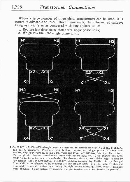
1,726 Transformer Connections
Where a large number of three phase transformers can be used, it is generally advisable to install three phase units, the following advantages being in their favor as compared with single phase units:
1. Require less floor space than three single phase units; 2. Weigh less than the single phase units;
Ftcs. 2,447 to 2,450.-Pittsburgh polarity diagrams. In accordance with A.I.E.E., N .E.L.A. and E.P.0 standards. Pittsburgh distribution transformers, single phase. 200 koa. and smaller, with high voltage, rating 7,500 volts and lower, are additive polarity. Heretofore. Pittsburgh distribution transformers were subtractive polarity. This change has been made to conform to present standards. To change polarity, cross either high tension or low tension leads as here shown. Fig. 2,447, additive polarity; fig. 2,448, polarity changed from additive to subtractive by crossing the low tension leads; fig. 2,449, polarity changed from additive to subtractive, by crossing the high tension leads; fig. 2450, polarity changed from additive to subtractive by crossing the low tension leads; low tension in parallel.
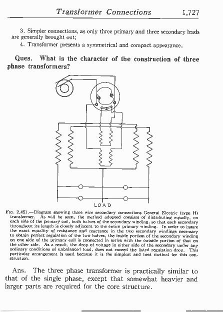
Transformer Connections 1,727
3. Simpler connections, as only three primary and three secondary leads are generally brought out;
4. Transformer presents a symmetrical and compact appearance.
Ques. What is the character of the construction of three phase transformers?
LOAD FIG. 2,451 -Diagram showing three wire secondary connections General Electric (type I-1)
transformer. As w ill be seen, the method adopted consists of distributing equally, on each side of the primary coil, both halves of the secondary winding, so that each secondary throughout its length is closely adjacent to the entire primary winding. In order to insure the exact equality of resistance and reactance in the two secondary windings necessary to obtain perfect regulation of the two halves, the inside portion of the secondary winding on one side of the primary coil is connected in series with the outside portion of that on the other side. As a result, the drop of voltage in either side of the secondary under any ordinary conditions of unbalanced load, does not exceed the listed regulation drop. This particular arrangement is used because it is the simplest and best method for this con- struction.
Ans. The three phase transformer is practically similar to that of the single phase, except that somewhat heavier and larger parts are required for the core structure.
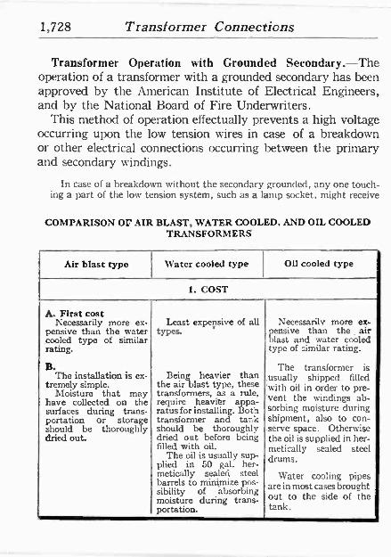
1,728 Transformer Connections
Transformer Operation with Grounded Secondary.-The operation of a transformer with a grounded secondary has been approved by the American Institute of Electrical Engineers, and by the National Board of Fire Underwriters.
This method of operation effectually prevents a high voltage occurring upon the low tension wires in case of a breakdown or other electrical connections occurring between the primary and secondary windings.
In case of a breakdown without the secondary grounded, any one touch- ing a part of the low tension system, such as a lamp socket, might receive
COMPARISON Or AIR BLAST, WATER COOLED. AND OIL COOLED TRANSFORMERS
Air blast type Water cooled type Oil cooled type
1. COST
A. First cost Necessarily more ex- Least expensive of all Necessarily more ex-
pensive than the water types. pensive than the air cooled type of similar blast and water cooled rating. type of similar rating.
B. The transformer is The installation is ex- Being heavier than .usually shipped . filled
tremely simple. Moisture that may
the air blast type, these transformers, as a rule, ,with oil in order to pre -
have collected on the require heavier appa- vent the windings ab - surfaces during trans- ratusforinstalling. Both 'sorbing moisture during portation or storage transformer and tank shipment, also to con - should be thoroughly should be thoroughly serve space. Otherwise dried out. dried out before being the oil is supplied in her -
filled with oil. metically sealed steel The oil is usually sup-
plied in 50 gal. her- drums. metically sealed steel Water cooling pipes barrels to minimize pos- are in most cases brought sibility of absorbing moisture during trans- out to the side of the portation. tank.
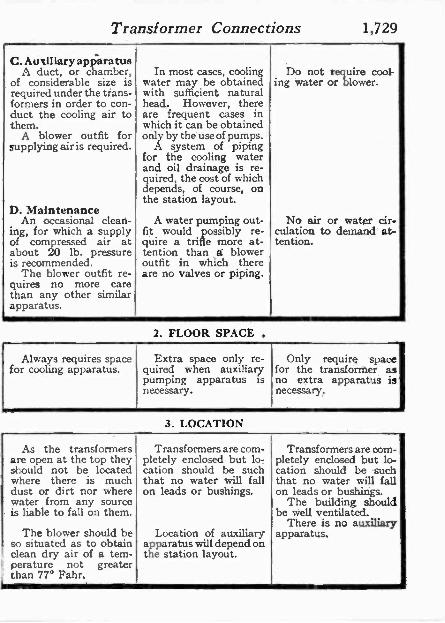
Transformer Connections 1,729
C. Auxiliary apparatus A duct, or chamber,
of considerable size is required under the trans- formers in order to con- duct the cooling air to them.
A blower outfit for supplying air is required.
D. Maintenance An occasional clean-
ing, for which a supply of compressed air at about 20 lb. pressure is recommended.
The blower outfit re- quires no more care than any other similar apparatus.
In most cases, cooling water may be obtained with sufficient natural head. However, there are frequent cases in which it can be obtained only by the use of pumps.
A system of piping for the cooling water and oil drainage is re- quired, the cost of which depends, of course, on the station layout.
A water pumping out- fit would possibly re- quire a trifle more at- tention than á blower outfit in which there are no valves or piping.
2. FLOOR SPACE .
Do not require cool- ing water or blower.
No air or water cir- culation to demand at- tention.
Always requires space Extra space only re- Only require space for cooling apparatus. quired when auxiliary for the transformer as
pumping apparatus is no extra apparatus is necessary. necessary.
3. LOCATION
As the transformers Transformers are com- Transformers are oom- are open at the top they pletely enclosed but lo- pletely enclosed but lo - should not be located cation should be such cation should be such where there is much that no water will fall that no water will fall dust or dirt nor where on leads or bushings. on leads or bushings. water from any source The building should is liable to fall on them. be well ventilated.
There is no auxiliary The blower should be Location of auxiliary apparatus.
so situated as to obtain apparatus will depend on clean dry air of a tem- perature not greater
the station layout.
1 than 77° Fahr.
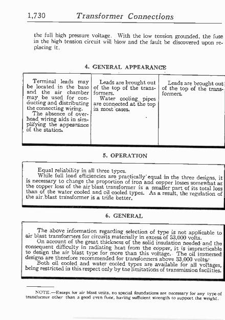
1,730 Transformer Connections
the full high pressure voltage. With the low tension grounded, the fuse in the high tension circuit will blow and the fault he discovered upon re- placing it.
4. GENERAL APPEARANCE
Terminal leads may be located in the base and the air chamber may be used for con- ducting and distributing the connecting wiring.
The absence of over- head wiring aids in sim- plifying the appearance of the station,
Leads are brought out of the top of the trans- formers.
Water cooling, pipes are connected at the top in most cases.
Leads are brought out of the top of the trans- formers.
5. OPERATION
Equal reliability in all three types. While full load efficiencies are practically' equal in the three designs, it is necessary to change the proportion of iron and copper losses somewhat as' the copper loss of the air blast transformer is a smaller part of its total loss l than of the water cooled and oil cooled types. As a result, the regulation of the air.blast transformer is a trifle better.
6. GENERAL
The above information regarding selection of type is not applicable to air blast transformers for circuits materially in excess of 33,000 volts. On account of the great thickness of the solid insulation needed and the consequent difficulty in radiating heat from the copper, it is impracticable to design the air blast type for more than this voltáge. The oil immersed designs are therefore recommended for transformers above 33,000 volts,' Both oil cooled and water cooled types are available for all voltages, being restricted in this respect only by the limitations of transmission facilities.
NOTE.-Except for air blast units, no special foundations are necessary for any type of transformer other than a good even floor, having sufficient strength to support the weight.
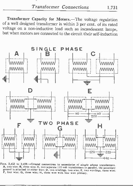
Transformer Connections 1,731
Transformer Capacity for Motors.-The voltage regulation of a well designed transformer is within 3 per cent. of its rated voltage on a non -inductive load such as incandescent lamps, but when motors are connected to the circuit their self-induction
SINGLE PHASE B
- TWO PHASE G
C
V\nNwv
H
kAAMA,ti
Fins. 2.452 to 2,459.-Ground connections to secondaries of single phase transformers. A, two wire; B, three wire; C, two separate 110 volt transformers in parallel, the secondary ground is attached to either wire; D, two windings, two wire; E, two windings, three wire; F, four wire; G, three wire; H, three wire with four wire primary.
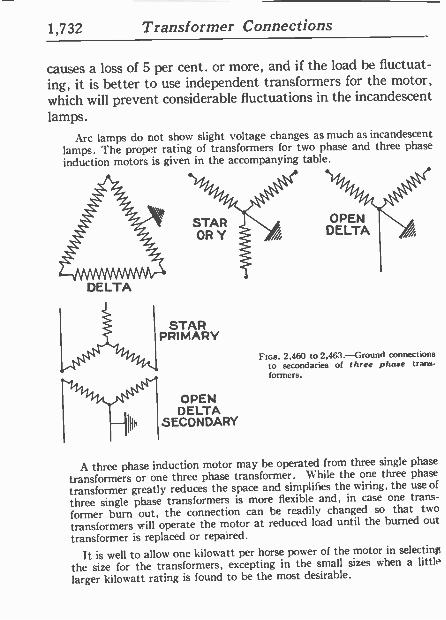
1,732 Transformer Connections
causes a loss of 5 per cent. or more, and if the load be fluctuat- ing, it is better to use independent transformers for the motor, which will prevent considerable fluctuations in the incandescent lamps.
Arc lamps do not show slight voltage changes as much as incandescent lamps. The proper rating of transformers for two phase and three phase
induction motors is given in the accompanying table.
DELTA
STAR PRIMARY
OPEN DELTA
SECONDARY
Fins. 2,460 to 2,463.-Ground connect ions to secondaries of three phase trans- formers.
A three phase induction motor may be operated from three single phase
transformers or one three phase transformer. While the one three phase
transformer greatly reduces the space and simplifies the wiring, the use of
three single phase transformers is more flexible and, ín case one trans-
former burn out, the connection can be readily changed so that two
transformers will operate the motor at reduced load until the burned out
transformer is replaced or repaired.
It is well to allow one kilowatt per horse power of the motor in selecting
the size for the transformers, excepting in the small sizes when a little,
larger kilowatt rating is found to be the most desirable.

Transformer Connections 1,733
Transformers for Two and Three Phase Motors..
Delivered voltage of
circuit
Single phase transformer voltages
110 volt motor 220 volt motor
Primary Secondary Primary Secondary
1,100 2,200
1,100 2,200
122 12
1,100 2,200
244 244
Very small transformers should not be used, even when the motor is large compared to the work it has to do, as the heavy starting current may burn them out.
The following tables give the proper sizes of transformer for three types of induction motor and the approximate current taken by three phase induction motors at 220 volts.
Capacities of Transformers for Induction Motors
Size of motor horse power
Kilowatts per transformer
Two single phase
transformers
Three single phase
Transformers
One three phase
ransformer
1 0.6 0.6 2 1.5 1.0 2.0 3 2.0 1.5 3.0 5 3.0 2.0 5.0 7 4.0 3.0 7.5
10 5.0 .4.0 10.0 15 7.5 5:0 15.0 20 10.0 7.5 20.0 30 15.0 10.0 30.0 50 25.0 15.0 50.0 75 40.0 25.0 75.0
100 50.0 30.0 100.0
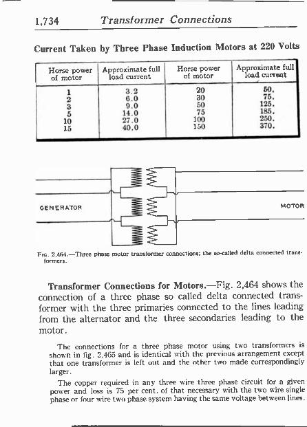
1,734 Transformer Connections
Current Taken by Three Phase Induction Motors at 220 Volts
Horse power of motor
Approximate full load current
Horse power of motor
Approximate full load current
1 3.2 20 50. 2 6.0 30 75. 3 9.0 50 125. 5 14.0 75 185.
10 27.0 100 250. 15 40.0 150 370.
GENERATOR MOTOR
Ftc. 2.464 -Three phase motor transformer connections; the so-called delta connected trans- formers.
Transformer Connections for Motors.-Fíg. 2,464 shows the connection of a three phase so called delta connected trans- former with the three primaries connected to the lines leading from the alternator and the three secondaries leading to the motor.
The connections for a three phase motor using two transformers is
shown in fig. 2.465 and is identical with the previous arrangement except that one transformer is left out and the other two made correspondingly larger.
The copper required in any three wire three phase circuit for a given power and loss is 75 per cent. of that necessary with the two wire single phase or four wire two phase system having the same voltage between lines.
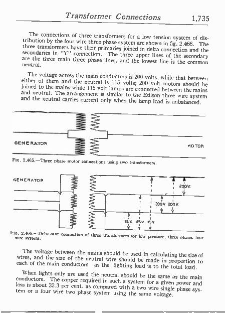
Transformer Connections 1,735
The connections of three transformers for a low tension system of dis- tribution by the four wire three phase system are shown in fig. 2.466. The three transformers have their primaries joined in delta connection and the secondaries in "Y" connection. The three upper lines of the secondary are the three main three phase lines, and the lowest line is the common neutral.
The voltage across the main conductors is 200 volts, while that between either of them and the neutral is 115 volts; 200 volt motors should be joined to the mains while 115 volt lamps are connected between the mains and neutral. The arrangement is similar to the Edison three wire system and the neutral carries current only when the lamp load is unbalanced.
GENERATOR
Fte. 2,465.-Three phase motor connections using t'ao transformers.
A A r3
MOTOR
2dO V ,
i 4, Á
i
20ov 2obV.
Ntc. 2.466.-Delta-star connection of three transformers for low pressure, three phase, four wire system.
The voltage between the mains should he used in calculating the size of wires, and the size of the neutral wire should he made in proportion to each of the main conductors as the lighting load is to the total load. When lights only are used the neutral should be the same as the main conductors. The copper required in such a system for a given power and loss is about 33.3 per cent. as compared with a two wire single phase sys- tem or a four wire two phase system using the same voltage.
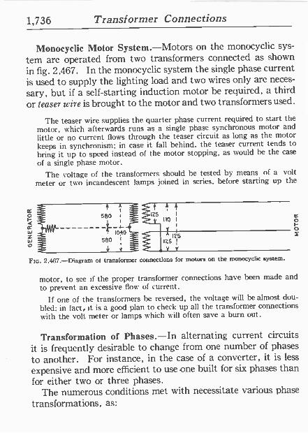
1,736 Transformer Connections
Monocyclic Motor System.-Motors on the monocyclic sys-
tem are operated from two transformers connected as shown
in fig. 2,467. In the monocyclic system the single phase current is used to supply the lighting load and two wires only are neces-
sary, but if a self-starting induction motor be required, a third or leaser wire is brought to the motor and two transformers used.
The teaser wire supplies the quarter phase current required to start the motor, which afterwards runs as a single phase synchronous motor and little or no current flows through the teaser circuit as long as the motor keeps in synchronism; in case it fall behind, the teaser current tends to bring it up to speed instead of the motor stopping, as would be the case
of a single phase motor.
The voltage of the transformers should he tested by means of a volt meter or two incandescent lamps joined in series, before starting up the
o F o
Ftc. 2,467.-Diagram of transformer connections for motors on the monocyclic system.
motor, to see if the proper transformer connections have been made and to prevent an excessive flow of current.
If one of the transformers be reversed, the voltage will be almost dou- bled; in fact. it is a good plan to check up all the transformer connections with the volt meter or lamps which will often save a burn out.
Transformation of Phases.-In alternating current circuits it is frequently desirable to change from one number of phases
to another. For instance, in the case of a converter, it is less
expensive and more efficient to use one built for six phases than for either two or three phases.
The numerous conditions met with necessitate various phase transformations, as:
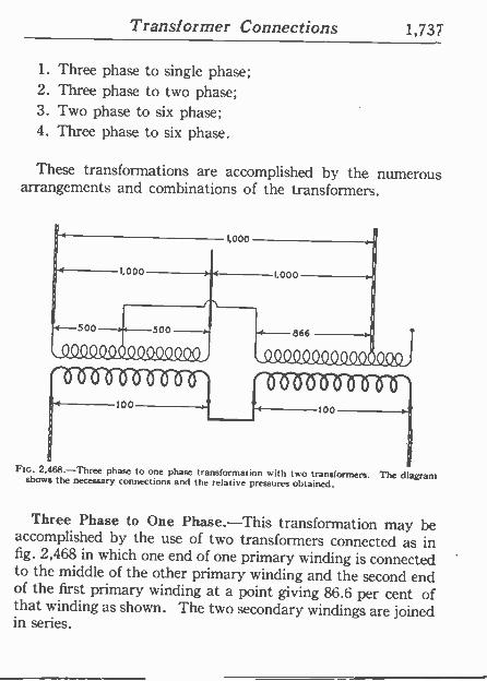
Transformer Connections 1,737
1. Three phase to single phase; 2. Three phase to two phase; 3. Two phase to six phase; 4. Three phase to six phase.
These transformations are accomplished by the numerous arrangements and combinations of the transformers.
FIG. 2,468.-Three phase to one phase transformation with two transformers. The diagram shows the necessary connections and the relative pressures obtained.
Three Phase to One Phase.-This transformation may be accomplished by the use of two transformers connected as in fig. 2,468 in which one end of one primary winding is connected to the middle of the other primary winding and the second end of the first primary winding at a point giving 86.6 per cent of that winding as shown. The two secondary windings are joined in series.
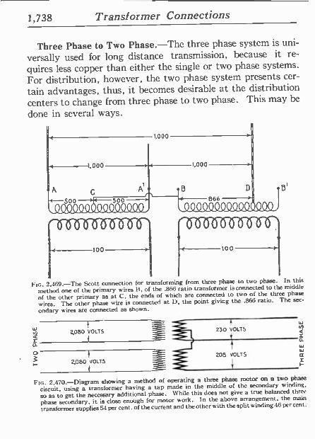
1,738 Transformer Connections
2080 VOLTS
Three Phase to Two Phase.-The three phase system is uni-
versally used for long distance transmission, because it re-
quires less copper than either the single or two phase systems.
For distribution, however, the two phase system presents cer-
tain advantages, thus, it becomes desirable at the distribution centers to change from three phase to two phase. This may be
done in several ways.
1
500
000
111111, 500
11111161
11111/1111
100
1,000
4 1,000
866 1111111 1111111
1111111111
100
FIG. 2,469.-The Scott connection for transforming from three phase to two phase. In this
method one of the primary wires It, of the .866 ratio transformer is connected to the middle
of the other primary as at C. the ends of which are connected to two of the three phase
wires. The other phase wire is connected at D, the point givicg the .866 ratio. The sec-
ondary wires arc connected as shown.
_ a
230 VOLTS
o $
}
2,080{vOLT3 209 VOLTS
FIG. 2,470.-Diagram showing a method of operating a three phase motor on a two phase
circuit. using a transformer having a tap made in the middle of the secondary winding.
so as to get the necessary additional phase. While this dues not give a true balanced three
phase secondary, it is close enough for motor work. In the above arrangement, the main
transformer supplies 54 per cent. of the current and the other with the split winding 46 per cent.
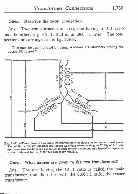
Transformer Connections 1,739
Ques. Describe the Scott connection.
Ans. Two transformers are used, one having a 10:1 ratio and the other, a Z J3 : 1, that is, an .866 : 1 ratio. The con- nections are arranged as in fig. 2,469.
This may be accomplished by using standard transformers having the ratios 10: 1, and 9: 1.
N
Ftc. 2.471.-Three phase to two phase transformation with three star connected transformers. Two of the secondary windings are tapped at points corresponding to 57.7% of full volt- age; these two windings are connected in series to form one secondary phase of voltage equal to that obtained by the other full secondary winding.
Ques. What names are given to the two transformers?
Ans. The one having the 10 : 1 ratio is called the main transformer, and the other with the 8.66: 1 ratio, the teaser transformer.
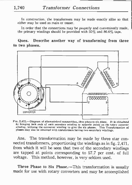
1,740 Transformer Connections
In construction, the transformers may be made exactly alike so that either may be used as main or teaser.
In order that the connections may be properly and conveniently made, the primary windings should be provided with 50% and 86.6% taps.
Ques. Describe another way of transforming from three to two phases.
FIG. 2,472.-Diagram of diametrical connection, three phase to six phase. It is obtained by bringing both ends of each secondary winding to opposite points on the rotary converter winding, utilizing the converter winding to give the six phases. This Transformation of phases may also be obtained with transformers having two secondary windings.
Ans. The transformation may be made by three star con- nected transformers, proportioning the windings as in fig. 2,471, from which it will be seen that two of the secondary windings are tapped at points corresponding to 57.7 per cent. of full voltage. This method, however, is very seldom used.
Three Phase to Six Phase.-This transformation is usually made for use with rotary converters and may be accomplished
Transformer Connections 1,741
in several ways. As these methods have been illustrated in the chapter on Converters, it is unnecessary to again discuss them here. Fig. 2,472, shows the diametrical connection for transforming three phase to six phase.
TEST QUESTIONS
1. How are single phase connections made? 2. Give directions for paralleling transformers. 3. What is the method of comparing instantaneous
polarities? 4. Draw a sketch showing two phase transformer con-
nect ions. 5. Give four methods of three phase connections. 6. What is the difference between the star and delta
connections? 7. What advantage has the star connection over the delta
connect ion? 8. What advantages are obtained with the delta connec-
tion? . 9. /low are transformers connected for four wire three
phase distribution? 10. What kind of transformers are used for three
phase current? 11. What points are to be considered in choosing between
three phase and single phase transformers Pr three phase current transformation?
12. What is the character of the construction of three phase transformers?
1,742 Transformer Connections
13. Should a transformer be operated with a grounded secondary?
14. Give a comparison of air blast, water cooled, and oil cooled transformers.
15. What may be said about transformer capacity for motors?
16. Draw some diagrams showing transformer connec- tions for motors.
17. What is a monocyclic motor system? 18. In what ways may transformation of phases be
made? 19. Describe the Scott connection. 20. What names are given to the two transformers used
in the Scott connection?
1
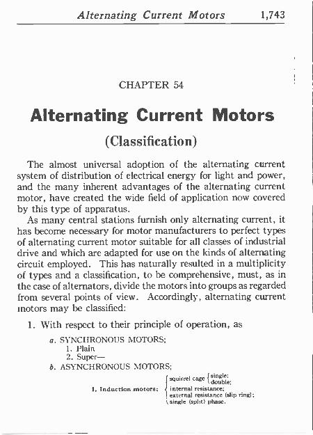
Alternating Current Motors 1,743
CHAPTER 54
Alternating Current Motors (Classification)
The almost universal adoption of the alternating current system of distribution of electrical energy for light and power, and the many inherent advantages of the alternating current motor, have created the wide field of application now covered by this type of apparatus.
As many central stations furnish only alternating current, it has become necessary for motor manufacturers to perfect types of alternating current motor suitable for all classes of industrial drive and which are adapted for use on the kinds of alternating circuit employed. This has naturally resulted in a multiplicity of types and a classification, to be comprehensive, must, as in the case of alternators, divide the motors into groups as regarded from several points of view. Accordingly, alternating current motors may be classified:
1. With respect to their principle of operation, as
a. SYNCHRONOUS MOTORS; 1. Plain 2. Super-
b. ASYNCHRONOUS MOTORS; squirrel cage {single;
double; 1. Induction motors; internal resistance;
external resistance (slip ring); single (split) phase.
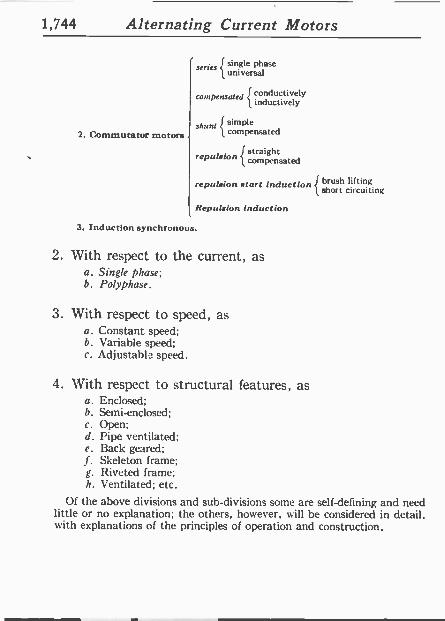
1,744 Alternating Current Motors
2. Commutator motors
series {
single phase universal
compensated conductively inductively -
shunt simple compensated
repulsion straight compensated
repulsion start induction brush liking short circuiting
Repulsion induction
3. Induction synchronous.
2. With respect to the current, as a. Single phase; b. Polyphase.
3. With respect to speed, as a. Constant speed; b. Variable speed; c. Adjustable speed.
4. With respect to structural features, as a. Enclosed; b. Semi -enclosed; c. Open; d. Pipe ventilated; e. Back geared; f. Skeleton frame; g. Riveted frame; h. Ventilated; etc.
Of the above divisions and sub -divisions some are self -defining and need little or no explanation; the others, however, will be considered in detail. with explanations of the principles of operation and construction.
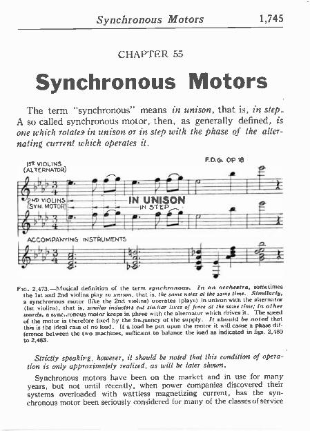
Synchronous Motors 1,745
CHAPTER 55
Synchronous Motors The term "synchronous" means in unison, that is, in step..
A so called synchronous motor, then, as generally defined, is one which rotate, in unison or in step with the phase of the alter- nating current which operates it.
Is. VIOLINS (ALTERNATOR)
3 1717(117-1
ND VIOLINS; SYN. MOTOR);
., rill e
IN UNISON
ACCOMPANYING INSTRUMENTS
b
F.D.G. OP 18
9
r í
IN STEP ! C } 10, i U
el
b -g j
FIG. 2,473.-Musical definition of the term synchronous. In an orchestra, sometimes
the 1st and 2nd violins play in unison, that is, the same 'roles al the same time. Similarly, a synchronous motor (like the 2nd violins) operates (plays) in unison with the alternator (1st violins), that is, similar inductors cut similar lines of force al the sane time; in other words, a sync,.ronous motor keeps in phase with the alternator which drives it. The speed
of the motor is therefore fixed by the frequency of the supply. It should be noted that this is the ideal case of no load. If a load he put upon the motor it will cause a phase dir. ference between the two machines, sufficient to balance the load as indicated in figs. 2,480
to 2,483.
Strictly speaking, however, it should be noted that this condition of opera- tion is only approximately realized, as will be later shown.
Synchronous motors have been on the market and in use for many years, but not until recently, when power companies discovered their systems overloaded with wattless magnetizing current, has the syn- chronous motor been seriously considered for many of the classes of service
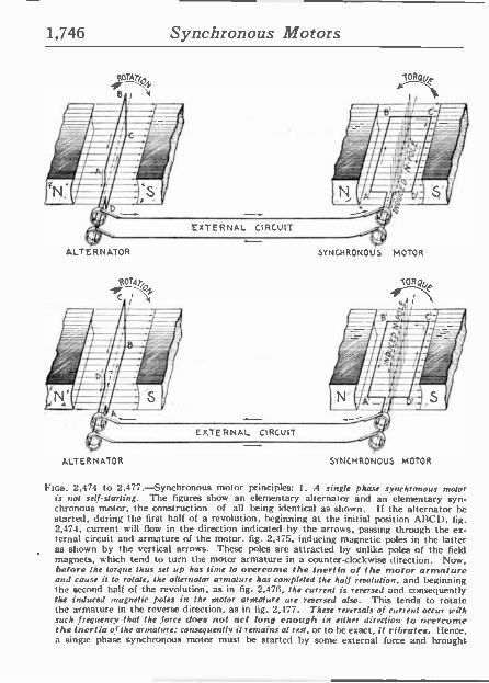
1,746 Synchronous Motors
ALTERNATOR
ALTERNATOR
SYNCHRONOUS MOTOR
SYNCHRONOUS MOTOR
Ftcs. 2,474 to 2,477.-Synchronous motor principles: I. A single phase synchronous motor is not self-starting. The figures show an elementary alternator and an elementary syn- chronous motor, the construction of all being identical as shown. If the alternator be started, during the first half of a revolution, beginning at the initial position ABC!), fig. 2,474, current will flow in the direction indicated by the arrows, passing through the ex- ternal circuit and armature of the motor. fig. 2,475, inducing magnetic poles in the latter as shown by the vertical arrows. These poles are attracted by unlike poles of the field magnets, which tend to turn the motor armature in a counter -clockwise direction. Now, before the torque thus set up has time to overcome the inertia of the motor armature and cause it to rotate, the alternator armature has completed the half revolution, and beginning the second half of the revolution, as in fig. 2,476, the current is reversed and consequently the induced magnetic poles in the motor armature are reversed also. This tends to rotate the armature in the reverse direction, as in fig. 2,477. These reversals of current occur u ith such frequency that the force does not act long enough in either direction to overcome the inertia of the armature; consequently it remains al rest, or to he exact , it vibrates. I lence, a single phase synchronous motor must be started by some external force and brought
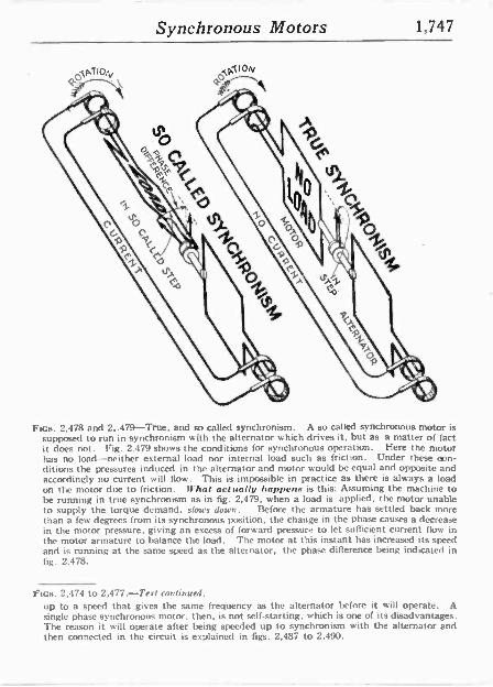
Synchronous Motors 1,747
FIGs. 2,478 and 2..479-True, and so called synchronism. A so called synchronous motor is supposed to run in synchronism with the alternator which drives it, but as a matter of fact it does not. Fig. 2.479 shows the conditions for synchronous operation. Here the motor has no load-neither external load nor internal load such as friction. Under these con- ditions the pressures induced in the alternator and motor would be equal and opposite and accordingly no current will flow. This is impossible in practice as there is always a load on the motor due to friction. What actually happens is this: Assuming the machine to be running in true synchronism as in fig. 2,479, when a load is applied, the motor unable to supply the torque demand, slows down. Before the armature has settled back more than a few degrees from its synchronous position, the change in the phase causes a decrease in the motor pressure, giving an excess of forward pressure to let sufficient current flow in the motor armature to bala
ahe s the alternator, the phase differencead. The motor at this instant has
uncreased its
being indicated in and is running at the same speed fig. 2,478.
ftcs. 2,474 to 2,477.-Text continued. up to a speed that gives the same frequency as the alternator before it will operate. A single phase synchronous motor, then, is riot self-starting. which is one of its disadvantages. The reason it will operate after being speeded up to synchronism with the alternator and then connected in the circuit is explained in figs. 2,487 to 2.490.
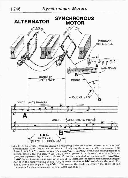
1,748 Synchronous Motors
A SYNCHRONOUS
ALTERNATOR MOTOR
PH(R)ASE DIFFERENCE
VIOLINS (SYNCHRONOUS MOTOR) >_.
LAG INTERVAL -.
TWEEN PH(R)ASES
FIGS. 2,480 to 2,483.-Musical analogy illustrating phase difference between alternator and synchronous motor due to load on motor. Analyzing the music, which is a passage from Scene 2, Act 3 of Bruno Oscar Klein's opera "Kenilworth," even those having little or no musical knowledge will clearly see that a vocal phrase A, is followed at a time interval (ph(r)ase difference) by a similar phrase. B, in the orchestral accompaniment. Similarly, if AA', be an instantaneous position of one of the alternator inductors, the corresponding in- ductor in the motor will lag behind AA', at some position as BB', to balance the load. Fig. 2.482, shows the angle of lag AOB. The greater the load, the greater the angle of lag; the reason for this is explained in figs. 2,493 and 2,494.
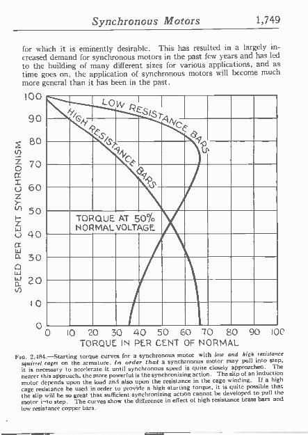
Synchronous Motors 1,749
for which it is eminently desirable. This has resulted in a largely in- creased demand for synchronous motors in the past few years and has led
to the building of many different sizes for various applications, and as time goes on, the application of synchronous motors will become much more general than it has been in the past.
!00
90
80
70
60
50
40
30
20
10
O
ti iGy LOW REST T
/STyti
C
cF 6.45
r
TORQUE AT 50% NORMAL VOLTAGE
0 10 20 30 40 50 GO 70 80 90 IOC
TORQUE IN PER CENT OF NORMAL
Fw. 2.484.-Starting torque curves for a synchronous motor with low and high resistance
squirrel cages on the armature. /n order that a synchronous motor may pull into step,
it is necessary to accelerate it until synchronous speed is quite closely approaches. The
nearer this approach, the more powerful is the synchronizing action. The slip of an induction
motor depends upon the load and also upon the resistance in the cage winding. If a high
cage resistance he used in order to provide a high starting torque, it is quite possible that the slip will be so great that sufficient synchronizing action cannot be developed to pull the
motor i"to step. The curves show the difference in effect of high resistance brass bars and
low resistance copper bars.
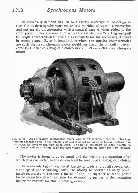
1,750 Synchronous Motors
The increasing demand has led to a careful investigation of design so that the modern synchronous motor is a machine of special construction and not merely an alternator with a squirrel cage winding added to the rotor poles. They are now built with very satisfactory "starting and pull in torque characteristics" which also accounts for the increasing demand in recent years. Even in installations where the starting characteristics are such that a synchronous motor would not start, the difficulty is over- come by the use of a magnetic clutch in conjunction with the synchronous motor.
.t*
.4.74.1111: n; ',
- .3 .
1r
F[c. 2,485.-Allis Chalmers synchronous motor with direct connected exciter. This type machine is made only in the smaller sizes and is of self-contained or bracket bearing con- struction for more or less high speed work. The feet of the stator yoke rest directly on the base or slide rails, a base being provided where three bearing belted parts are required.
The motor is brought up to speed and thrown into synchronism after which it is connected to the driven load by means of the magnetic clutch.
The uniformly high efficiency at fractional loads and at all speeds, con- stant speed under varying loads, the ability to operate at unity power factor regardless of the power factor of the line together with the power factor corrective effect that may be obtained by increasing the excitation are prime reasons for this increasing demand.
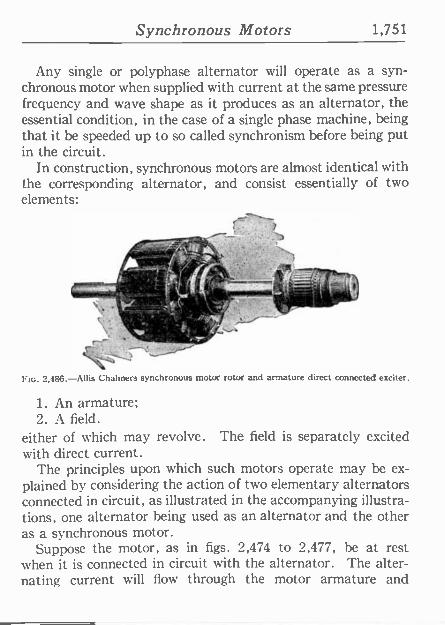
Synchronous Motors 1,751
Any single or polyphase alternator will operate as a syn- chronous motor when supplied with current at the same pressure frequency and wave shape as it produces as an alternator, the essential condition, in the case of a single phase machine, being that it be speeded up to so called synchronism before being put in the circuit.
In construction, synchronous motors are almost identical with the corresponding alternator, and consist essentially of two elements:
A
/3lc º.rr
- - -., .. ,
. T.
FIG. 2,486.-Allis Chalmers synchronous motor rotor and armature direct connected exciter.
1. An armature; 2. A field.
either of hich may revolve. The field is separately excited with direct current.
The principles upon which such motors operate may be ex- plained by considering the action of two elementary alternators connected in circuit, as illustrated in the accompanying illustra- tions, one alternator being used as an alternator and the other as a synchronous motor.
Suppose the motor, as in figs. 2,474 to 2,477, be at rest when it is connected in circuit with the alternator. The alter- nating current will flow through the motor armature and
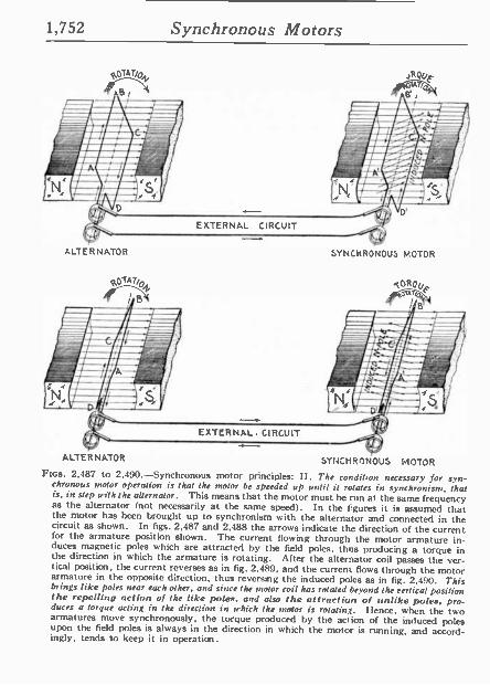
1,752 Synchronous Motors
ALTERNATOR
01A7/0
! B
EXTERNAL CIRCUIT
EXTERNAL. CIRCUIT
,,RQuF U7/O
SYNCHRONOUS MOTOR
.tOROU purr F
i B
ALTERNATOR SYNCNRMNOUS t'IOTOR Fins. 2,487 to 2,490.-Synchronous motor principles: II. The condition necessary for syn-
chronous motor operation is that the motor be speeded up until it rotates in synchronism, that is, in step with the alternator. This means that the motor must be run at the same frequency as the alternator (not necessarily at the same speed). In the figures it is assumed that the motor has been brought up to synchronism with the alternator and connected in the circuit as shown. In figs. 2,487 and 2,488 the arrows indicate the direction of the current for the armature position shown. The current flowing through the motor armature in- duces magnetic poles which are attracted by the field poles, thus producing a torque in the direction in which the armature is rotating. After the alternator coil passes the ver- tical position, the current reverses as in fig. 2,489, and the current flows through the motor armature in the opposite direction, thus reversing the induced poles as in fig. 2,490. This brings like poles near each other, and since the motor coil has rotated beyond the vertical position the repelling action of the like poles, and also the attraction of unlike poles, pro- duces a torque acting in the direction in which the motor is rotating. I ence, uu hen the two armatures move synchronously, the torque produced by the action of the induced poles upon the field poles is always in the direction in which the motor is running, and accord- ingly, tends to keep it in operation.
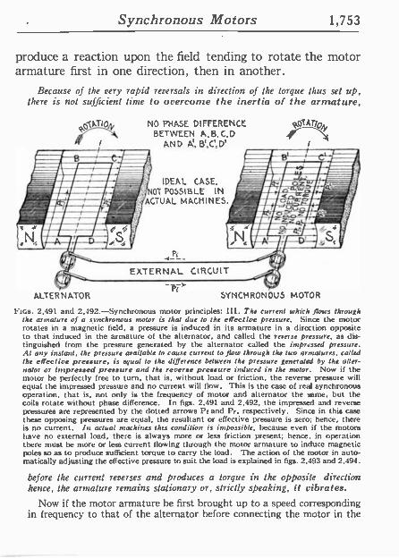
Synchronous Motors 1,753
produce a reaction upon the field tending to rotate the motor armature first in one direction, then in another.
Because of the very rapid reversals in direction of the torque thus set up, there is not sufficient time to overcome the inertia of the armature,
pZATfO NO PHASE DIFFERENCE BETWEEN A, B,C,D
t AND A, B',C',D'
IDEAL CASE, OT POSSIBLE IN
ACTUAL MACHINES.
EXTERNAL CIRCUIT
ALTERNATOR SYNCHRONOUS MOTOR
Fins. 2.491 and 2,492-Synchronous motor principles: Ill. The current which flows through the armature of a synchronous motor is that due to the effect lve pressure. Since the motor rotates in a magnetic field, a pressure is induced in its armature in a direction opposite to that induced in the armature of the alternator, and called the reverse pressure, as dis- tinguished from the pressure generated by the alternator called the impressed pressure. At any instant, the pressure available to cause current to flow through the two armatures, called the effective pressure, is equal to the difference between the pressure generated by the alter- nator or Impressed pressure and the reverse pressure induced in the motor. Now if the motor be perfectly free to turn, that is, without load or friction, the reverse pressure will equal the impressed pressure and no current will flow. This is the case of real synchronous operation, that is, not only is the frequency of motor and alternator the lime, but the coils rotate without phase difference. In figs. 2,491 and 2,492, the impressed and reverse pressures are represented by the dotted arrows Pr and Pr, respectively. Since in this case these opposing pressures are equal, the resultant or effective pressure is zero; hence, there is no current. In actual machines this condition is impossible, because even if the motors have no external load, there is always more or less friction present; hence, in operation there must be more or less current flowing through the motor armature to induce magnetic poles so as to produce sufficient torque to carry the load. The action of the motor in auto- matically adjusting the effective pressure to suit the load is explained in figs. 2,493 and 2,494.
before the current reverses and produces a torque in the opposite direction hence, the armature remains stationary or, strictly speaking, it vibrates.
Now if the motor armature he first brought up to a speed corresponding in frequency to that of the alternator before connecting the motor in the
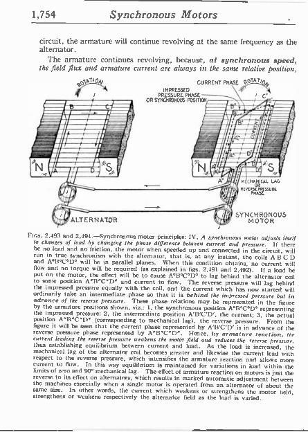
1,754 Synchronous Motors
circuit, the armature will continue revolving at the same frequency as the alternator.
The armature continues revolving, because, at synchronous speed, the field flux and armature current are always in the same relative position,
CURRENT PHASE R0T ,y IMPRESSED
PRESSURE PHASE t t;' OR SYNCHRONOUS POSITION _ ulRfitlNl,
Q yl t~nli Hl- fil r,vlrs Nfl rttl tiMdIMI,
ALTERNATOR
M CHANICAL LAG
REVERSE OR
PHASE
SYNCHRONOUS MOTOR
Ftcs. 2,493 and 2,494.-Synchronous motor principles: IV. A synchronous motor adjusts itself to changes of load by changing the phase difference between current and pressure. If there be no load and no friction, the motor when speeded up and connected in the circuit, will run in true synchronism with the alternator, that is. at any instant, the coils A B C D and A°13°C°D° will be in parallel planes. When this condition obtains, no current will flow and no torque will be required (as explained in figs. 2,491 and 2,492). If a load be put on the motor, the effect will he to cause A°B°C°D° to lag behind the alternator coil to some position A"13"C"D" and current to flow. The reverse pressure will lag behind the impressed pressure equally with the coil, and the current which has now started will ordinarily take an intermediate phase so that it is behind the impressed pressure but in advance of the reverse pressure. These phase relations may be represented in the figure by the armature positions shown, viz.: 1, the synchronous position A°B°C°D° representing the impressed pressure; 2. the intermediate position A'B'C'D', the current; 3. the actual position A"13"C"D" (corresponding to mechanical lag), the reverse pressure. From the figure it will be seen that the current phase represented by A'B'C'D' is in advance of the reverse pressure phase represented by A"B"C"D". Hence, by armature reaction. the current leading the reverse pressure weakens the motor field and reduces the reverse pressure, thus establishing equilibrium between current and load. As the load is increased, the mechanical lag of the alternator coil becomes greater and likewise the current lead with respect to the reverse pressure, which intensifies the armature reaction and allows more current to flow. In this way equilibrium is maintained for variations in load within the limits of zero and 90° mechanical lag. The effect of armature reaction on motors is just the reverse to its effect on alternators, which results in marked automatic adjustment between the machines especially when a single motor is operated from an alternator of about the same size. In other words, the current which weakens or strengthens the motor field, strengthens or weakens respectively the alternator field as the load is varied.
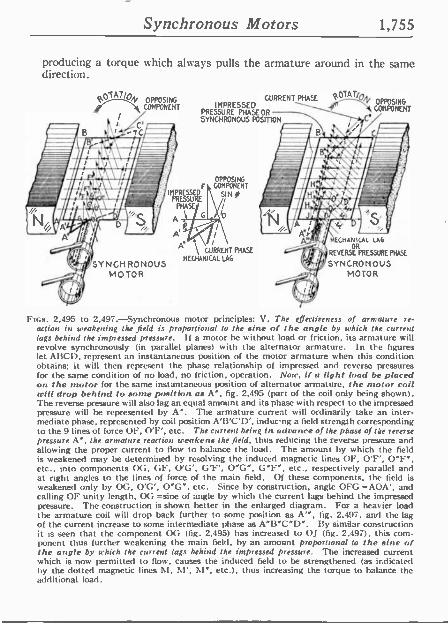
Synchronous Motors 1,755
producing a torque which always pulls the armature around in the same direction.
pTA7/pN OPPOSING COMPONENT
SYNCHRONOUS MOTOR
CURRENT PHASE .OT cA,, OPPOSING
SYNCHRONOUS POSITION PRESSURE PHASES OR
IMPRESS COMPONENT _.
IMPRESSED PRESSURE
PRASE
A D
OPPOSING COMPONENT
SIN 0
io
A del t CURRENT PHASE
MECHANICAL LAG
k MECHANICAL LAG
REVERSE PRESSURE PHASE
SYNCRONOUS MOTOR
FIGS. 2,495 to 2,497.-Synchronous motor principles: V. The eiectineness of armature re- action in weakening the field is proportional to the sine of the angle by which the current lags behind the impressed pressure. if a motor be without load or friction, its armature will revolve synchronously (in parallel planes) with the alternator armature. In the figures let ABCD, represent an instantaneous position of the motor armature when this condition obtains; it will then represent the phase relationship of impressed and reverse pressures for the same condition of no load, no friction, operation. Now, if a light ',rod be placed on the motor for the same instantaneous position of alternator armature, the motor coil will drop behind to some position as A", fig. 2,495 (part of the coil only being shown). The reverse pressure will also lag an equal amount and its phase with respect to the impressed pressure will be represented by A". The armature current will ordinarily take an inter- mediate phase, represented by coil position A'B'C'D', inducng a field strength corresponding to the 9 lines of force OF. O'F', etc. The current being in advance of the phase of the reverse pressure A", the armature reaction weakens the field, thus reducing the reverse pressure and allowing the proper current to flow to balance the load. The amount by which the field is weakened may be determined by resolving the induced magnetic lines OF, O'F', O"F", etc.. into components OG, GF, O'G', G'F', O"G", G"F", etc., respectively parallel and at right angles to the lines of force of the main field. Of these components, the field is weakened only by OG, O'G', O"G", etc. Since by construction, angle OFG =AOA', and calling OF unity length, OG =sine of angle by which the current lags behind the impressed pressure. The construction is shown better in the enlarged diagram. For a heavier load the armature coil will drop back further to some position as A'", fig. 2.497, and the lag of the current increase to some intermediate phase as A"B"C"D". Ily similar construction it is seen that the component OG (fig. 2,495) has increased to 0.1 (fig. 2.497), this com- ponent thus further weakening the main field, by an amount proportional to the sine of the angle by which the current lags behind the impressed pressure. The increased current which is now permitted to flow, causes the induced field to be strengthened (as indicated by the dotted magnetic lines M, M', M", etc.), thus increasing the torque to balance the additional load.
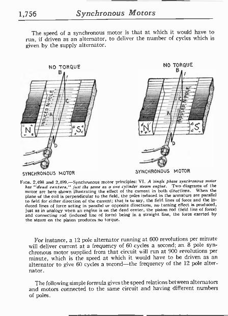
1,756 Synchronous Motors
The speed of a synchronous motor ís that at which it would have to run, if driven as an alternator, to deliver the number of cycles which is
given by the supply alternator.
NO TORQUE B -
SYNCHRONOUS MOTOR SYNCHRONOUS MOTOR
Ftos. 2,498 and 2,499.-Synchronous motor principles: VI. A 'sing([ phase synchronous motor has "dead centers." just the same as a one cylinder steam engine. Two diagrams of the motor are here shown illustrating the effect of the current in both directions. When the plane of the coil is perpendicular to the field, the poles induced in the armature are parallel to field for either direction of the current; that is to say, the field lines of force and the in- duced lines of force acting in parallel or opposite directions, no turning effect is produced, just as in analogy when an engine is on the dead center, the piston rod (field line of force) and connecting rod (induced line of force) being in a straight line, the force exerted by the steam on the piston produces no torque.
For instance, a 12 pole alternator running at 600 revolutions per minute will deliver current at a frequency of 60 cycles a second; an 8 pole syn- chronous motor supplied from that circuit will run at 900 revolutions per minute, which is the speed at which it would have to he driven as an alternator to give 60 cycles a second-the frequency of the 12 pole alter- nator.
The following simple formula gives the speed relations between alternators and motors connected to the same circuit and having different numbers of poles.
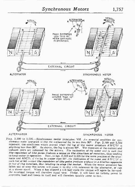
Synchronous Motors 1,757
ROTA
ALTERNATOR
ROTAl,y y
I
EXTERNAL CIRCUIT
ALTERNATORM
e 2 Ao
PHASE DIFFERENCE S LESS TM +.N 90° MOTOR CONTINUES
IN OPERATION
ALTERNATOR b.,1
p ¡ ó
PHASE DIFFERENCE GP.EATER THAN 90°
MOTOR STOPS
SYNCHRONOUS SOTOR
ROTA
\1
ALTERNATOR SYNCHRONOUS MOTOR
FIGS. 2.500 to 2,505.-Synchronous motor principles: VII. An essential condition for syn- chronous motor operation is that the mechanical lag he less than 90°. Figs. 2,500 and 2,502 represent the conditions which prevail when the lag of the motor armature AB'C'D' is anything less than 90°. As shown, the lag is almost 90°. The direction of the current and induced poles are indicated by the arrows. The inclination of the motor coil is such that the repulsion of like poles produces a torque in the direction of rotation, thus tending to keep motor in operation. Now, in figs. 2,503 and 2.505 for the same position of the alter- nator coil AI3C1), if t.':e lag be greater than 90°, the inclination of the motor coil A'I3'C'D' is such that at this instant the repulsion of like poles produces a torque in a direction opposite to that of the rotation, thus lending to stop the motor. When the motor armature has fallen out of step this action will cause it to slip with reference to the alternator, or run at a slower speed. When it has slipped a full half cycle the torque will again be forward; the resultant torque will therefore equal ..ero. Hence. it will have no turning power to overcome load and losses in itself and will therefore quickly come to rest.
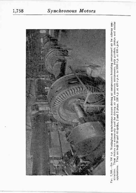
I t.n
00
' .
.. 1
4 ..'
,' 1-
IY
:.
6 1
I
` u
r. 4_
1'9
° "f
,°
T
. ,
_ .
l''11
-->
` :rt'
1
i ...
I
' '
FZ
':/".
.:11.
-:'
( ,.
'J
y o
i':7,
c`'Í
' Í
IT
or
r,rw
'i .
`'I.
-
- .
101.
:'-o
e .
l fy ,
'l:
ep .N
Y
n
" 1
41t!
.4
"'he
*4
NiR
w
,
.
:15
5-
! J. _ .
s"
...
I ¡F
f`.
FIG
. 2,
506.
-Six
300
h.p
. W
estin
ghou
se s
ynch
rono
us m
otor
s dr
ivin
g ai
r co
mpr
esso
rs f
urni
shin
g co
mpr
esse
d ai
r fo
r su
bway
con
- st
ruct
ion.
T
hese
m
otor
s ar
e ex
tens
ivel
y us
ed
for
driv
ing
air
and
amm
onia
com
pres
sors
, pu
lp g
rinde
rs,
pum
ps a
nd
sim
ilar
appl
icat
ions
. T
hey
are
built
50
and
60 c
ycle
s, 2
an
d 3
phas
e,
100
h.p.
at
400
r.p.
m.
to 5
000
h.p.
at
100
r.p.
is.
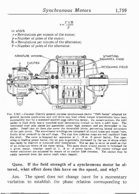
Synchronous Motors 1,759
r= 1'XR p
in which r = Revolutions per minute of the motor; p=Number of poles of the motor; R = Revolutions per minute of the alternator; P = Number of poles of the alternator.
STARTInG SQUIRREL CAGE
REVOLVING FIELD
il)
FIG. 2,507.-General Electric general purpose synchronous motor "7500 Series" adapted for general purpose application and will drive any load whose torque requirements have been successfully met by a standard squirrel cage induction motor. In construe! ion, the field spider is built from heavy punched steel laminations riveted to form a solid mass. The laminated steel pole pieces are assembler) under high pressure and are dovetailed to the spider. Small cast air fans also cover the dovetailed joints, preventing lateral movement of the pole pieces. The amortisseur windings are composed of round brass and copper bars, firmly silver soldered to the end rings. The cast iron collector rings are well insulated from the shaft. The rotor is designed for operation at 1, .9 or .8 power factor. For oper- ating at leading power factor, the air gap is generally decreased by the use of shims which can easily be inserted or removed after installation. The air gap is never as small as that of an induction motor of the same rating. The same shunt wound exciter is furnished for a given motor, whether rated at 1, .9 or .8 power factor. The exciter voltage and motor excitation are adjusted by means of an exciter field rheostat. The exciter may he easily removed from the motor shaft when desired.
Ques. If the field strength of a synchronous motor be al- tered, what effect does this have on the speed, and why?
Ans. The speed does not change (save for a momentary variation to establish the phase relation corresponding to
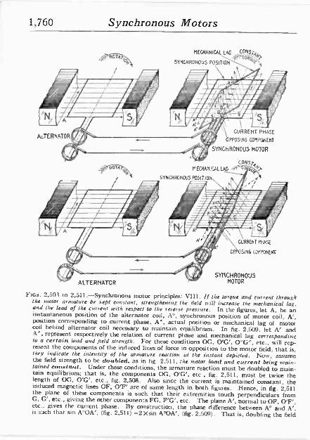
1,760 Synchronous Motors
ALTERNATOR
pOTAT'o s
ALTERNATOR
MECHANICAL LAG CONSTAN
SYNCHRONOUS POSITION YOrj
CURRENT PHASE
OPPOSING COMPONENT
SYNCHRONOUS MOTOR
CONSTA
MECHAIIICALIAG t'j0'OLP
SYNCHRONOUS POSITION
CURRENT PHASE
OPPOSING CONPOTIENT
SYNCHRONOUS MOTOR
FIGS. 2,501 to 2,511 -Synchronous motor principles: VIiI. If the torque and current through the nrotor armature be kept constant, strengthening the field will increase the mechanical lag, and the lead of the current with respect to the reverse pressure. In the figures, let A. be an instantaneous position of the alternator coil. A°, synchronous position of motor coil, A', position corresponding to current phase. A', actual position or mechanical lag of motor coil behind alternator coil necessary to maintain equilibrium. In fig. 2,509, let A' and A', represent. respectively the relation of current phase and mechanical lag corresponding to a certain load and field strength. For these conditions OG. O'G', O"G", etc., will rep- resent the components of the induced lines of force in opposition to the motor field, that is, they indicate the intensity of the armature reaction al the instant depicted. Now, assume the field strength to he doubled, as in fig. 2,511, the motor load and current being main- tained constant. Under these conditions, the armature reaction must be doubled to main- tain equilibrium; that is, the components OG, O'G', etc., fig. 2,511, must be twice the length of OG, O'G', etc., fig. 2,508. Also since the current is maintained constant, the induced magnetic lines OF, O'F' are of same length in both figures. Hence, in fig. 2,511 the plane of these components is such that their extremities touch perpendiculars from G, G', etc., giving the other components FG, F'G', etc. The plane A'. normal to OF, O'F', etc.. gives the current phase. By construction, the phase difference between A° and A'. is such that sin A°OA'. (fig. 2,511) =2 Xsin A°OA'. (fig. 2,509). That is, doubling the field
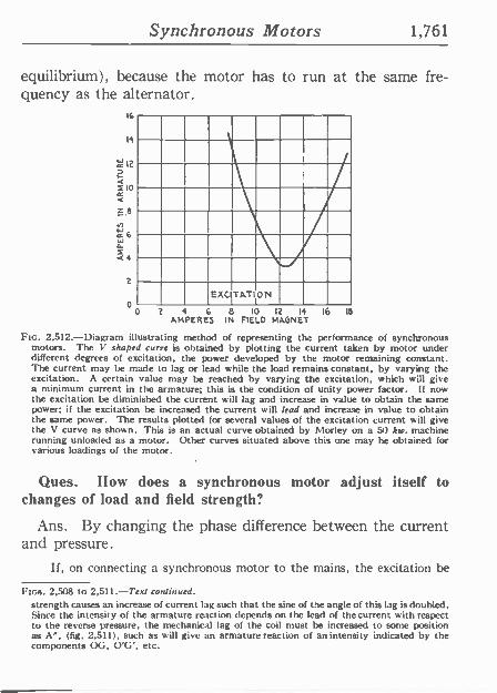
Synchronous Motors 1,761
equilibrium), because the motor has to run at the same fre- quency as the alternator.
16
EXCITATI ON
0 2 4 6 8 10 12 14 16 18
AMPERES IN FIELD MAGNET
Ftc. 2.512.-Diagram illustrating method of representing the performance of synchronous motors. The V shaped curve is obtained by plotting the current taken by motor under different degrees of excitation, the power developed by the motor remaining constant. The current may be made to lag or lead while the load remains constant, by varying the excitation. A certain value may he reached by varying the excitation, which will give a minimum current in the armature; this is the condition of unity power factor. 11 now the excitation be diminished the current will lag and increase in value to obtain the same power; if the excitation be increased the current will lead and increase in value to obtain the same power. The results plotted for several values of the excitation current will give the V curve as shown. This is an actual curve obtained by Morley on a 50 kw. machine running unloaded as a motor. Other curves situated above this one may be obtained for various loadings of the motor.
Ques. How does a synchronous motor adjust itself to changes of load and field strength?
Ans. By changing the phase difference between the current and pressure.
If, on connecting a synchronous motor to the mains, the excitation be
FIGS. 2,508 to 2,511.-Text continued. strength causes an increase of current lag such that the sine of the angle of this lag is doubled. Since the intensity of the armature reaction depends on the lead of the current with respect to the reverse pressure, the mechanicd lag of the coil must be increased to some position as A", (fig. 2,511), such as will give an armature reaction of an intensity indicated by the components OG, O'G', etc.
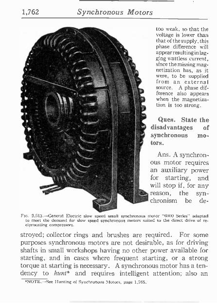
1,762 Synchronous Motors
,/-- 1
": R _ r:C
' r . Í . ..
*' . /!,.,_ 1*
fl
l1 1
1 `'
too weak, so that the voltage is lower than that of the supply, this phase difference will appear resulting in lag- ging wattless current, since the missing mag- netization has, as it were, to be supplied from an external source. A phase dif- ference also appears
2* when the magnetiza- tion is too strong.
v'
Ques. State the disadvantages of synchronous mo- tors.
Ans. A synchron- ous motor requires an auxiliary power for starting, and will stop if, for any reason, the syn- chronism be de -
FIG. 2,513.-General Electric slow speed small synchronous motor "6000 Series" adapted to meet the demand for slow speed synchronous motors suited to the direct drive of re- ciprocating compressors.
stroyed; collector rings and brushes are required. For some purposes synchronous motors are not desirable, as for driving shafts in small workshops having no other power available for starting, and in cases where frequent starting, or a strong torque at starting is necessary. A synchronous motor has a ten- dency to hunt* and requires intelligent attention; also an
*NOTE.-Sec Hunting of Synchronous Motors, page 1,765.
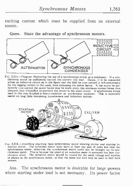
Synchronous Motors 1,763
exciting current which must be supplied from an external source.
Ques. State the advantage of synchronous motors.
ALTERNATOR SYNCHRONOUS CONDENSER
INDUGTIVEd CIRCUIT o
A0111(11___,
FIG. 2,514.-Diagram illustrating the use of a synchronous motor as a condenser. If a syn- chronous motor t e sufficiently excited the current will lead. Hence, if it be connected across an inductive circuit as in the figure and the field be over excited it willcompensa.e for the lagging current in the main, thus increasing the power factor. If the motor be suf- ficiently over excited the power factor may be made unity, the minimum current being thus obtained that will7suftice to transmit the power in the main circuit. A synchronous motor used in this way,is-called a rotary condenser or synchronous condenser. This is especially useful on long lines containing transformers and induction motors.
Fro. 2.515.-Auxiliary starting type synchronous motor showing exciter and starting in- duction motor. The induction motor must have at least one pair of poles less than the synchronous motor, otherwise the synchronous motor could not be brought up to syn- chronous speed. This is because the speed of an induction motor is somewhat less than syn- chronous speed. The induction motor should be wound for the same voltage and number of phases as the synchronous motor. so that the same bus bars may be used to feed both motors.
Ans. The synchronous motor is desirable for large powers where starting under load is not necessary. Its power factor
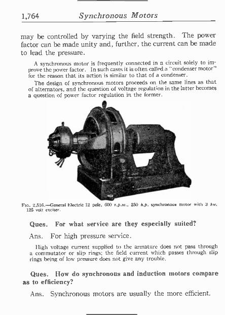
1,764 Synchronous Motors
may be controlled by varying the field strength. The power factor can be made unity and, further, the current can be made to lead the pressure.
A synchronous motor is frequently connected in a circuit solely to im- prove the power factor. In such cases it is often called a "condenser motor" for the reason that its action is similar to that of a condenser.
The design of synchronous motors proceeds on the same lines as that of alternators, and the question of voltage regulation in the latter becomes
a question of power factor regulation in the former.
k{ q .
.
111
it .
. GP .} ,:4 w .Y l $ .
6r. 7{{
1. .
FIG. 2,516.-General Electric 12 pole, 600 r.p.m., 250 h.p. synchronous motor with 3 kw. 125 volt exciter.
Ques. For what service are they especially suited?
Ans. For high pressure service.
High voltage current supplied to the armature does not pass through a commutator or slip rings; the field current which passes through slip rings being of low pressure does not give any trouble.
Ques. How do synchronous and induction motors compare as to efficiency?
Ans. Synchronous motors are usually the more efficient.
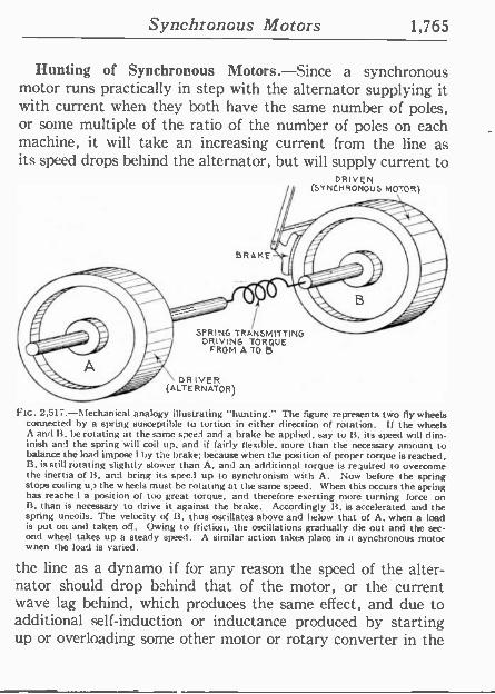
Synchronous Motors 1,765
Hunting of Synchronous Motors.-Since a synchronous motor runs practically in step with the alternator supplying it with current when they both have the same number of poles, or some multiple of the ratio of the number of poles on each machine, it will take an increasing current from the line as its speed drops behind the alternator, but will supply current to
DRIVEN (SYNCHRONOUS MOTOR}
BRAISE
SPRING TRANSMITTING DRIVING TORQUE
FROM A TO B
DRIVER (ALTERNATOR)
Fte. 2,517.-Mechanical analogy illustrating "hunting." The figure represents two fly wheels connected by a spring susceptible o tortion in either direction of rotation. If the wheels A and B. be rotating at the same speed and a brake he applied, say to B. its speed will dim- inish and the spring will coil tip, and if fairly flexible, more than the necessary amount to balance the load impose1 by the brake: because when the position of proper torque is reached, B, is still rotating slightly slower than A, and an additional torque is required to overcome the inertia of 14, and bring its spee I up to synchronism with A. Now before the spring stops coiling u? the wheels must be rotating at the same speed. When this occurs the spring has reache I a position of too great torque, and therefore exerting more turning force on B, than is necessary to drive it against the brake. Accordingly 13, is accelerated and the spring uncoils. The velocity of 13, thus oscillates above and below that of A, when a load is put on and taken off. Owing to friction, the oscillations gradually die out and the sec- ond wheel takes up a steady speed. A similar action takes place in a synchronous motor when the load is varied.
the line as a dynamo if for any reason the speed of the alter- nator should drop behind that of the motor, or the current wave lag behind, which produces the same effect, and due to additional self-induction or inductance produced by starting up or overloading some other motor or rotary converter in the
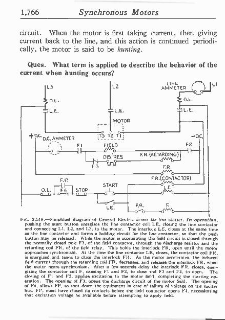
1,766 Synchronous Motors
circuit. When the motor is first taking current, then giving current back to the line, and this action is continued periodi- cally, the motor is said to be hunting.
Ques. What term is applied to describe the behavior of the current when hunting occurs?
L3 L2
0
L.E. L.E.
+ D'C'O.C. AMMETER
MOTOR
LINt AMMETER
O.L.
L. E.
;T3 T2 T lj
FI FIELD
-D.0 F2
DIS. RES.
F3
F. R.(RETAR DIN G
F.P.
F. P.
START O.L. F.4 STOP
L.E. F.R.
s^^"a- F. R. (CONTACTO R)
L.E
LI
FIG. 2,518.-Simplified diagram of General Electric across the line starter. In operation, pushing the start button energizes the line contactor coil LE. closing the line contactor and connecting LI, L2, and 1,3, to the motor. The interlock LE, closes at the same time as the line contactor and forms a holding circuit for the line contactor. so that the push button may be released. While the motor is accelerating the field circuit is closed through the normally closed pole F3, of the field contactor, through the discharge resistor and the retarding coil FR, of the field relay. This holds the interlock FR, open until the motor approaches synchronism. At the time the line contactor LE, closes, the contactor coil FR, is energized and tends to clase the interlock FR. As the motor accelerates, the induced field current through the retarding coil FR, decreases, and releases the interlock FR, when the motor nears synchronism. After a few seconds delay the interlock FR, closes, ener- gizing the contactor coil F, causing Fl and F2, to close and F3 and F4, to open. The closing of Fl and F2, applies excitation to the motor field, completing the starting op- eration. The opening of F3, opens the discharge circuit of the motor field. The opening of F4. allows FI', to shut down the equipment in case of failure of voltage on the exciter bus. FI', must have closed its contacts before the field contactor opens 1.4, necessitating that excitation voltage be available before attempting to apply field.
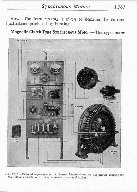
Synchronous Motors 1,767
Ans. The term surging is given to describe the current fluctuations produced by hunting.
Magnetic Clutch Type Synchronous Motor.-This type motor
FIG. 2.519.-Pictured representation of General Electric across (he line starter showing its connections and relations to a synchronous motor an exciter.
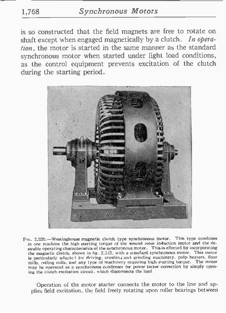
1,768 Synchronous Motors
is so constructed that the field magnets are free to rotate on shaft except when engaged magnetically by a clutch. In opera- tion, the motor is started in the same manner as the standard synchronous motor when started under light load conditions, as the control equipment prevents excitation of the clutch during the starting period.
Ftc. 2.520.-Westinghouse magnetic clutch type synchronous motor. This type combines in one machine the high starting torque of the wound rotor induction motor and the de- sirable operas ing characteristics of the synchronous motor. This is effected by incorporating the magnetic' dutch. shown in fig. 2,522, with a standard synchronous motor. This motor is particularly adapted for driving. crushin, and grinding machinery, pulp beaters, flour mills, rolling mills, and any type of machinery requiring high starting torque. The motor may he operated as a synchronous condenser for power factor correction by simply open- ing the clutch excitation circuit, which disconnects the load
Operation of the motor starter connects the motor to the line and ap- plies field excitation, the field freely rotating upon roller bearings between
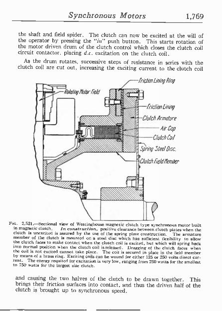
Synchronous Motors 1,769
the shaft and field spider. The clutch can now be excited at the will of the operator by pressing the "in" push button. This starts rotation of the motor driven drum of the clutch control which closes the clutch coil circuit contactor, placing d.c. excitation on the clutch coil.
As the drum rotates, successive steps of resistance in series with the clutch coil are cut out, increasing the exciting current to the clutch coil
friction Lining Ring
SPA Motor field 174 \\`tt.
{t
f %..
11I
so
friction Lining
Clutch Armature
Air Cop
Clutch Coil
Spring Steel Disc.
Clutch fie/d/temder
-,.,.........
II Frc. 2,521.-Sectional view of Westinghouse magnetic clutch type s; nchronous motor built
in magnetic clutch. In construction, positive clearance between clutch plates when the clutch is unexcited is assured by the use of the spring plate construction. The armature member of the clutch is mounted on a steel disc which has sufficient flexibility to allow the clutch faces to make contact when the clutch coil is excited, but which will spring back into normal position when the clutch coil is released. Dragging of the clutch faces when the coil is not excited cannot take place. The coil is secured in place in the field member by means of a brass ring. Exciting coils can he wound for either 125 or 250 volts direct cur- rent. The energy requited for excitation is very low, ranging from 250 watts for the smallest to 750 watts for the largest size clutch.
and causing the two halves of the clutch to he drawn together. This brings their friction surfaces into contact, and thus the driven half of the clutch is brought up to synchronous speed.
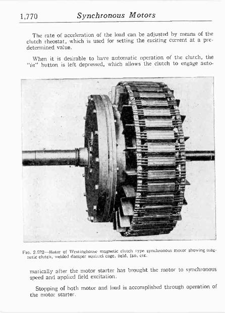
1,770 Synchronous Motors
The rate of acceleration of the load can be adjusted by means of the clutch rheostat, which is used for setting the exciting current at a pre- determined value.
When it is desirable to have automatic operation of the clutch, the "in" button is left depressed, which allows the clutch to engage auto-
er : 3 jl
.
~
%tr.",- ,
1,t1L,
.t,. - ír.4. -
Flo. 2.522-Rotor of Westinghouse magnetic clutch type synchronous motor showing mag-
netic clutch, welded damper squirrel cage, field, fan, etc.
matically after the motor starter has brought the motor to synchronous speed and applied field excitation.
Stopping of both motor and load is accomplished through operation of
the motor starter.
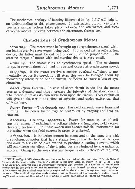
Synchronous Motors 1,771
The mechanical analogy of hunting illustrated in fig. 2,517 will help to an understanding of this phenomenon. In alternating current. circuits a precisely similar action takes place between the alternators and syn- chronous motors, or even between the alternators themselves.
Characteristics of Synchronous Motors
*Star t ing.-The motor must he brought up to synchronous speed with- out load, a starling compensalorbeing used. If provided with a self-starting device, the latter must be cut out of circuit at the proper time. The starting torque of motor with self-starting device is very small.
Running.-The motor runs at synchronous speed. The maximum torque is several times full load torque and occurs at synchronous speed.
Stopping.-If the motor receive a sudden overload sufficient to mo- mentarily reduce its speed, it w ill stop; this may be brought about by momentary interruption of the current, sufficient to cause a loss of syn- chronism.
Effect Upon Circuit.-In case of short circuit in the line the motor acts as a dynamo and thus increases the intensity of the short circuit. The motor impresses its own wave form upon the circuit. Over excitation will' give to the circuit the effect of capacity, and under excitation, that of inductance.
Power Factor.-This depends upon the field current, wave form and. hunting. The power factor may he controlled by varying the field ex- citation.
Necessary Auxiliary Apparatus.-Power for starting, or if self- starting, means of reducing the voltage while starting; also, fieki exciter, rheostat, friction clutch, main switch and exciter switch, instruments for indicating when the field current is properly adjusted.
Adaptation.-If induction motors he connected to the same line with a synchronous motor that has a steady load, then the field of the syn- chronous motor can be over excited to produce a leading current, which will counteract the effect of the lagging currents induced by the induction motors. Owing to the weak starting torque, skilled attendance required,
*NOTE.-Fig. 2,515 shows the auxiliary motor method of starting. Another method is to provide the motor with a starting winding in the pole faces as shown in fig. 2,486. This is an auxiliary squirrel cage or amortisseur winding and consists of a number of metal rods embedded in the pole faces and interconnected with and brazed to short circuiting rings. The action of the squirrel cage is fully explained in the chapter on squirrel cage induction motors. The squirrel cage also tends to damp out oscillations of the armature (called "hunt- ;ng") and because of this action the wind.ng is sometimes called a "damping winding."
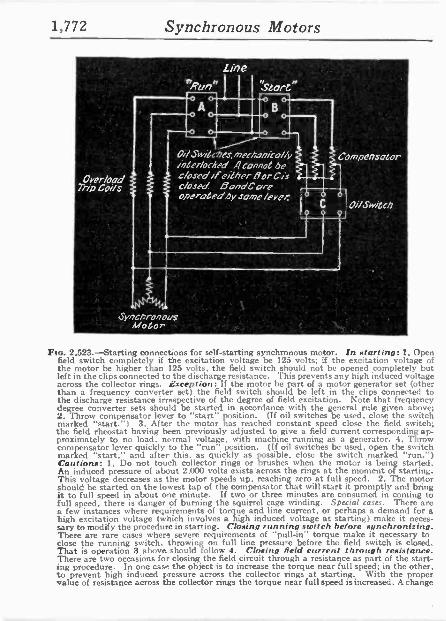
1,772 Synchronous Motors
.
LLinee "Runn ` Slart"
SwiGces,mettanico//y inóer/onYed Atonnot be t/osPdileilhenBorCis closed BondCare operaLedby same/eye/:
Fta. 2,523.-Starting connections for self-starting synchronous motor. In starting: 1, Open field switch completely if the excitation voltage be 125 volts; if the excitation voltage of the motor be higher than 125 vo ts, the field switch should not be opened completely but left in the clips connected to the discharge resistance. This prevents any high induced voltage across the collector rings. Exception: If the motor be part of a motor generator set (other than a frequency converter set) the field switch should be left in the clips connected to the discharge resistance irrespective of the degree of field excitation. Note that frequency degree converter sets should be started in accordance with the general rule given above; 2, Throw compensator lever to "start" position. (If oil switches be used, close the switch marked "start.") 3. After the motor has reached constant speed close the field switch; the field rheostat having been previously adjusted to give a field current corresponding ap- proximately to no load, normal voltage, with machine running as a generator. 4, Throw compensator lever quickly to the "run position. (If oil switches be used, open the snitch marked "start," and after this, as quickly as possible. close the switch marked "run.") Cautions: 1, Do not touch collector rings or brushes when the motor is being started. An induced pressure of about 2,000 volts exists 'across the rings at the moment of starting. This voltage decreases as the motor speeds up, reaching zero at full speed. 2, The motor should be started on the lowest tap of the compensator that will start it promptly and bring it to full speed in about one minute. If two or three minutes are consumed in coming to full speed, there is danger of burning the squirrel cage winding. Special cases. There are a few instances where requirements of torque and line current, or perhaps a demand for a high excitation voltage (which involves a high induced voltage at starting) make it neces- sary to modify the procedure in starting. Closing running switch before synchronizing. There are rare cases where severe requirements of "pull -in" torque make it necessary to close the running switch. throwing on full line pressure before the field switch is closed. That is operation 3 above should follow 4. Closing field current through resistance. There are two occasions for closing the field circuit through a resistance as part of the start- ing procedure. In one case the object is to increase the torque near full speed; in the other, to prevent high induced pressure across the collector rings at starting. With the proper value of resistance across the collector rings the torque near full speed is increased. A change
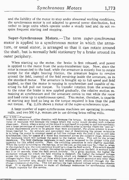
Synchronous Motors 1,773
and the liability of the motor to stop under abnormal working conditions, the synchronous motor is not adapted to general power distribution, but rather to large units which operate under a steady load and do not re- quire frequent starting and stopping.
Super -Synchronous Motors.-The term super -synchronous motor is applied to a synchronous motor in which the arma- ture, or usual stator, is arranged so that it can rotate around the shaft, but is normally held stationary by a brake around its outer periphery.
When starting up the motor, the brake is first released, and power is applied to the motor from the auto -transformer taps. Now, since the rotor is connected to the load, while the armature is entirely free to rotate except for the slight hearing friction, the armature begins to revolve around the field, instead of the field revolving inside the armature, as in the standard motor. The armature is brought up to full speed and field applied, so that the motor is running in synchronism and capable of ex- erting its full pull out torque. To transfer rotation from the armature to the rotor the brake is now applied gradually, the relative motion re- maining at synchronism and the armature comes to rest while the rotor and load come up to synchronous speed. This motor, therefore, is capable of starting any load so long as the torque required is less than the pull out torque. Fig. 2,524 shows a motor of the super -synchronous type.
A large number of super -synchronous machines are operating in cement mills, and two 500 h.p. motors are in use driving brass rolling mills.
FIG. 2.523.-Conf i n n ed from this resistance in either direction will decrease the torque. At starting, however, any value of resistance will decrease the torque which the motor would develop with collector rings open. Hence, when a motor at the time it is purchased is required to pull into synchron- ism a large percentage of normal load, or when conditions arise in service where the "pull -in" torque requirements prove to be greater than were anticipated, the above scheme is some- times resorted to. An accurate and convenient way of determining the proper resistance is to bring the motor to constant speed at full line voltage with the load it has to pull into synchronism; then by means of a water box connected across the collector rings, determine the resistance which will increase the speed to the highest value. This will be the proper resistance. The field discharge resistance in such case is increased to the proper value and capacity for this added service. Here, the switching procedure is only slightly modified. When the motor is running on the last tap, or on the line, as the case may be,-that is, when in the standard case. the next operation would be to close the field switch. This switch should be closed on the first point, thereby throwing the resistance across the field. A moment later say 5 or 10 seconds, close the field switch entirely. On a given machine, the higher the excitation voltage for which the field winding is designed, the higher the induced voltage across the collector rings at starting. Motors which are designed for normal excitation voltages higher than 125 volts, or those which form part of motor generator sets other than frequency converter sets, should have the field winding short circuited through the dis- charge resistance at starting. This will prevent the high induced voltage across the collector rings. It is standard practice to make all discharge resistances for synchronous motors of ample capacity for this service.
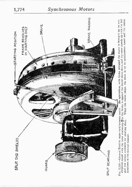
1,774 Synchronous Motors
4 cc m
- _-_-_._-.-;.-,-----s R! f-¡:._ G R
m
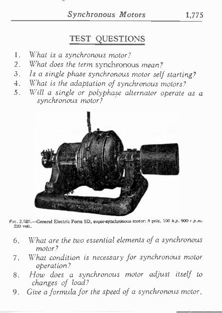
Synchronous Motors 1,775
TEST QUESTIONS
1. What is a synchronous motor? 2. What does the term synchronous mean? 3. Is a single phase synchronous motor self starting? 4. What is the adaptation of synchronous motors? 5. Will a single or polyphase alternator operate as a
synchronous motor?
IL' ' w
w¡
R¡ -.r: ., .l
` , '", LtN . .'. ,.1 T MCo
I o .../M1 /o f,.v :. :.,^.";r.C. ._ ,' "y'
7., .+.:
- a, FIG. 2,525. ---General Electric Form SD, super -synchronous motor: 8 pole, 100 h.p. 900 r.p.m.
220 volt.
6. What are the two essential elements of a synchronous motor?
7. What condition is necessary for synchronous motor operation?
8. How does a synchronous motor adjust itself to changes of load?
9. Give a formula for the speed of a synchronous motor.
1,776 Synchronous Motors
10. If the field strength of a synchronous motor be al- tered, what effect does this have on the speed, and why?
11. State the advantages and disadvantages of synchron- ous motors.
12. For what service are synchronous motors especially suited?
13. Define the term hunting. 14. What term is applied to describe the behavior of the
current when hunting occurs? 15. Give the characteristics of synchronous motors. 16. What is a super -synchronous motor?
Squirrel Cage Motors 1,777
CHAPTER 56
Polyphase Induction Motors 1. Squirrel Cage Type
By definition a squirrel cage motor is an asynchronous* motor, in which the currents supplied are led through the field coils only, and the armature, not being connected to the ex- ternal circuit, is rotated by currents induced by the varying field set up through the field coils.
The operation of a polyphase induction motor depends on the production of a rotating magnetic field by passing alter- nating currents through the field magnets. This means that the poles produced by the alternating currents are constantly changing their positions relative to the field winding, the latter being stationary; hence, the term rotating magnetic field.
An optical analogy of a rotating magnetic field may be ob- tained by watching a flasher sign having a rotating border.
The polyphase squirrel cage type induction motor possesses many inherent advantages which have made it one of the most extensively used types of electrical apparatus.
Extremely simple in construction and reliable in operation, it may he built so rugged as to he used under the most -rying conditions, and in exposed locations. The squirrel cage type, having no wearing parts except the bearings, assures freedom from sparking so that it may he placed with safety where, on account of the fire hazard, a direct current machine would be dangerous.
NOTE.-The term asynchronous means not coinciding with respect to time, not occurring simultaneously, hence, briefly, not in step. Accordingly, an asynchronous motor is a motor which does not run in step with the alternations of the current.
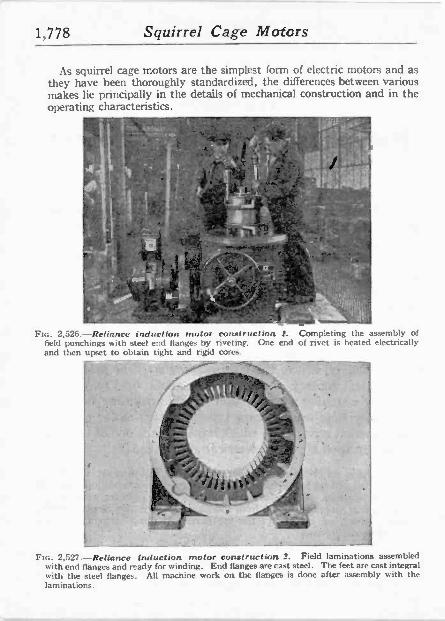
1,778 Squirrel Cage Motors
As squirrel cage motors are the simplest form of electric motors and as they have been thoroughly standardized, the differences between various makes lie principally in the details of mechanical construction and in the operating characteristics.
- rJ
!;9y{l ''''''''''ppp
o
FIG. 2,526.-Relinnce induction motor construction 2. Completing the assembly of field punchings with steel end flanges by riveting. One end of rivet is heated electrically and then upset to obtain tight and rigid cores.
termer
Flo. 2,527 -Reliance induction motor construction 2. Field laminations assembled with end flanges and ready for winding. End flanges are cast steel. The feet are cast integral with the steel flanges. All machine work on the flanges is done after assembly with the laminations.
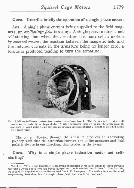
Squirrel Cage Motors 1,779
Ques. Describe briefly the operation of a single phase motor.
Ans. A single phase current being supplied to the field mag- nets, an oscillating* field is set up. A single phase motor is not self-starting; but when the armature has been set in motion by external paeans, the reaction between the magnetic field and the induced currents in the armature being no longer zero, a torque is produced tending to turn the armature.
Ftc. 2,528. Reliance induction motor construction 2. The details are: 1, slot cell insulation extends 3. in. beyond slot; 2, fibre separator inserted in slot between coils; 3. slot stick; 4. oiled muslin used for insulating coils between phases; 5, heads of coils are taped
ith linen tape.
The current flowing through the armature produces an alternating polarity such that the attraction between the unlike armature and field poles is always in one direction, thus producing the torque.
Ques. Why is a single phase induction motor not self- starting?
*NOTE.-"The word oscillating is becoming specialized in its application to those currents and fields whose oscillations are being damped out, as in electric 'oscillations.' But for this, we should have spoken of an oscillating field."-S. P. Thompson. The author believes the word reciprocating, best describes the single phase field, and should be here used.
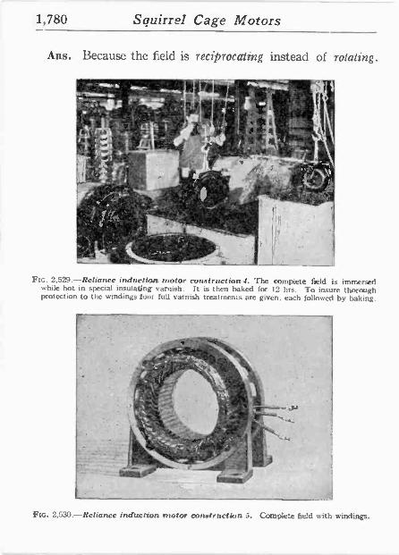
1,780 Squirrel Cage Motors
Ans. Because the fe1d is reciprocating instead of rotating.
_ T . f '' -. Ill =rti - r'`j 11 °t 1-, ,k 6
f" _Q i"1 , ° 3 .,S I :
'AO 41 kr.- ., ,
L113."..1 .14 o ' ¢ y (",' i ^ ..2.' -
i 7 S <
.
° ,
'
l .' _
` _
__._ ..
_ I 1
:,zó ' * _,:id ._ 'ic,. ` 191'
yk_. 'Mo-1. G o
'-'1":":1,,,j, d..., .
b
.i 11 .
, rr
'G....,"J .-.L o-'i--ti"1
' ` P 111
Q ---
`l'''" fil
Yí, ... f igÁ o 1
4 n
I
Fin. 2.529.-Reliance induction motor construction 4. The complete field is immersed while hot in special insulating varnish. It is then baked (or 12 hrs. To insure thorough protection to the windings lour lull varnish treatments are given, each followed by baking.
Fin. 2,530.-Reliance induction motor construction 5. Complete field with windings.
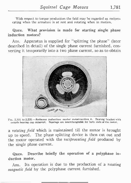
Squirrel Cage Motors 1,781
With respect to torque production the field may be regarded as recipro- cating when the armature is at rest and rotating when in motion.
Ques. What provision is made for starting single phase induction motors?
Ans. Apparatus is supplied for "splitting the phase" (later described in detail) of the single phase current furnished, con- verting it temporarily into a two phase current, so as to obtain
FIG. 2.531 o 2,535.-Reliance induction motor construction 6. Bearing bracket with outside bearing cap removed. Bearings are interchangeable for both ends of the motor.
a rotating field which is maintained till the motor is brought up to speed. The phase splitting device is then cut out and the motor operated with the reciprocating field produced by the single phase current.
Ques. Describe briefly the operation of a polyphase in- duction motor.
Ans. Its operation is due to the production of a rotating magnetic field by the polyphase current furnished.
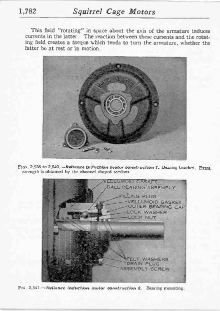
1,782 Squirrel Cage Motors
This field "rotating" in space about the axis of the armature induces currents in the latter. The reaction between these currents and the rotat- ing field creates a torque which tends to turn the armature, whether the latter be at rest or in motion.
FIGS. 2,536 to 2.510.-Reliance h iduction motor construction 7. Bearing bracket. Extra strength is obtained by the channel shaped sections.
I .---- - . .V ASKET
;BALL'BEARINGASSEMBLY -
' :. : - FILLING PLUG . = .
. . eVELLUMQID"GASKET -yjOUTER BEARING CAP I
LOCK WASHER 1191911úRr LOCK NUT.' 1 * '
-R ` 1
F'i.._
\\ ,' y . ---,---,........_____FELT. WASHERS
y. ^, IN '..:,,-1--, DRAIN PLUG - ,r.'-." _ ASSEMBLY SCREW f;
r'.-.. FIG. 2.541.-Reliance inductlors motor construction 8. Bearing mounting.
J
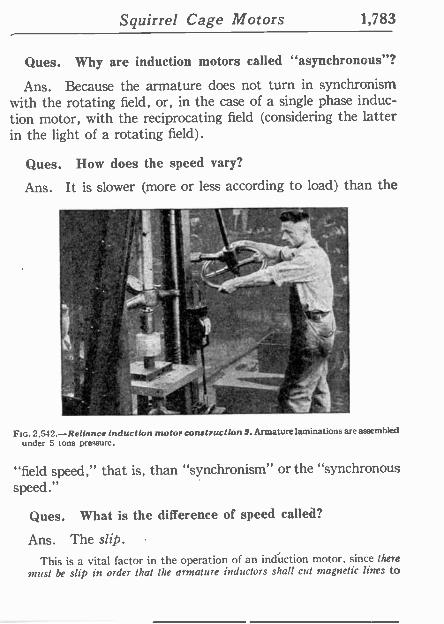
Squirrel Cage Motors 1,783
Ques. Why are induction motors called "asynchronous"?
Ans. Because the armature does not turn in synchronism with the rotating field, or, in the case of a single phase induc- tion motor, with the reciprocating field (considering the latter in the light of a rotating field).
Ques. How does the speed vary?
Ans. It is slower (more or less according to load) than the
Fin. 2,542.-Reliance induction motor construction 9. Armature laminations are assembled under S tons pressure.
"field speed," that is, than "synchronism" or the "synchronous speed."
Ques. What is the difference of speed called?
Ans. The slip.
This is a vital factor in the operation of an induction motor, since there most be slip in order that the armature inductors shalt cut magnetic lines to
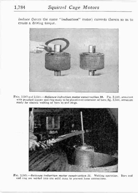
1,784 Squirrel Cage Motors
induce (hence the name "induction" motor) currents therein so as to create a driving torque.
-
Fins. 2,543 and 2,544.-Reliance induction motor construction I0. Fig. 2.543, armature with punched copper end ring ready to be placed over extension of bars; fig. 2,544, armature ready for electric welding of bars to end rings.
Fin. 2,545-Reliance induction motor construction II. Welding operation. Bars and end ring are welded into one solid mass to prevent loose connections.
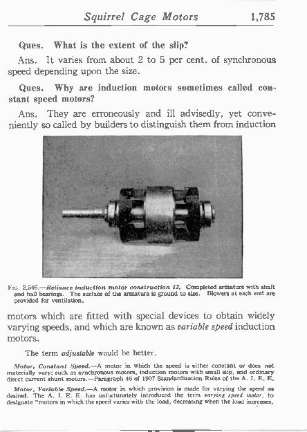
Squirrel Cage Motors 1,785
Ques. What is the extent of the slip?
Ans. It varies from about 2 to 5 per cent. of synchronous speed depending upon the size.
Ques. Why are induction motors sometimes called con- stant speed motors?
Ans. They are erroneously and ill advisedly, yet conve- niently so called by builders to distinguish them from induction
2,546.-Reliance induction motor construction 72. Completed armature with shaft and ball bearings. The surface of the armature is ground to size. Blowers at each end are provided for ventilation.
motors which are fitted with special devices to obtain widely varying speeds, and which are known as variable speed induction motors.
The term adjustable would be better.
Motor, Constant Speed.-A motor in which the speed is either constant or does not materially vary; such as synchronous motors, induction motors with small slip, and ordinary direct current shunt motors.-Paragraph 46 of 1907 Standardization Rules of the A. I. E. E.
Motor, Variable Speed.-A motor in which provision is made for varying the speed as desired. The A. I. E. E. has unfortunately introduced the term varying speed ,rotor, to designate "motors in which the speed varies with the load, decreasing when the load increases,
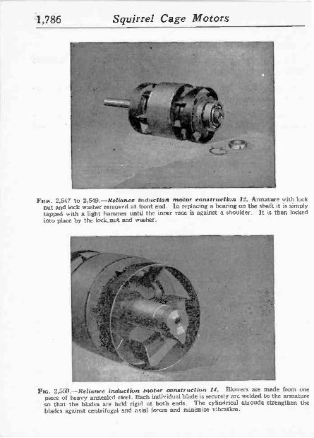
1,786 Squirrel Cage Motors
FIGS. 2,547 to 2,549.-Reliance induction motor construction Ii. Armature with lock nut and lock washer removed at front end. In replacing a bearing on the shaft it is simply tapped with a light hammer until the inner race is against a shoulder. It is then locked into place by the lock nut and washer.
tlfrfb.7
A.
p_ .
er+ rfx
y; ' lc`a : t` yº c
Etc. 2,550.-Reliance induction motor construction 14. Blowers are made from one piece of heavy annealed steel. Each individual blade is securely arc welded to the armature so that the blades are held rigid at both ends. The cylindrical shrouds strengthen the blades against centrifugal and axial forces and minimize vibration.
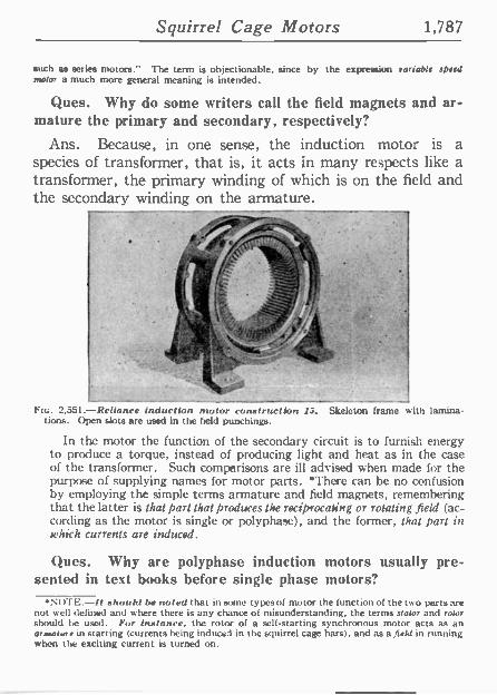
Squirrel Cage Motors 1,787
such as series motors." The term is objectionable, since by the expression variable speed motor a much more general meaning is intended.
Ques. Why do some writers call the field magnets and ar- mature the primary and secondary, respectively?
Ans. Because, in one sense, the induction motor is a species of transformer, that is, it acts in many respects like a transformer, the primary winding of which is on the field and the secondary winding on the armature.
Fta. 2,551.-Relianee induction motor construction 1.. Skeleton frame with lamina- tions. Open slots are used in the field punchings.
In the motor the function of the secondary circuit is to furnish energy to produce a torque, instead of producing light and heat as in the case of the transformer. Such comparisons are ill advised when made for the purpose of supplying names for motor parts. 'There can be no confusion by employing the simple terms armature and field magnets, remembering that the latter is that part that produces the reciprocating or rotating field (ac- cording as the motor is single or polyphase), and the former, that part in which currents are induced.
Ques. Why are polyphase induction motors usually pre- sented in text hooks before single phase motors?
*NOTE.-!t shook! be noted that in some types of motor the function of the two parts are not well defined and where there is any chance of misunderstanding, the terms stator and rotor should be used. For instance, the rotor of a self-starting synchronous motor acts as an ar..atine in starting (currents being induced in the squirrel cage bars), and as a field in running when the exciting current is turned on.
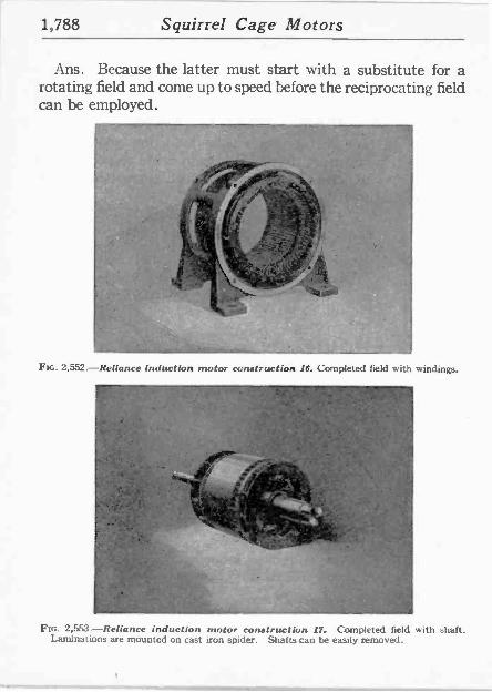
1,788 Squirrel Cage Motors
Ans. Because the latter must start with a substitute for a rotating field and come up to speed before the reciprocating field can be employed.
Fuc. 2,552.-Reliance induction motor construction 16. Completed field with windings.
Ftc. 2,553.-Reliance induction motor construction 17.. Completed field with shaft. Laminations are mounted on cast iron spider. Shafts can be easily removed.
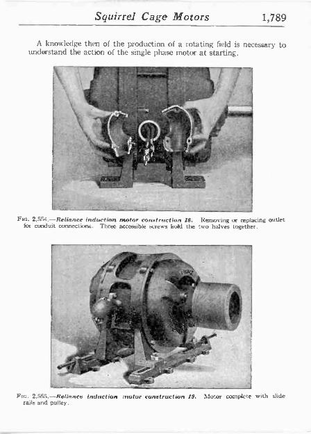
Squirrel Cage Motors 1,789
A knowledge then of the production of a rotating field is necessary to understand the action of the single phase motor at starting.
Fm. 2,S5l.-Reliance induction motor construction 18. Removing or replacing outlet for conduit connections. Three accessible screws hold the two halves together.
rrl ,,o
- , , . '`' '{ p,;:`S.
LL rI ?4-
rrrp, .-.y. / ' -r . - . . -- `_rr .` m"i
'3' .
2.555.-Reliance induction :motor construction 19. Motor complete with slide rails and pulley.
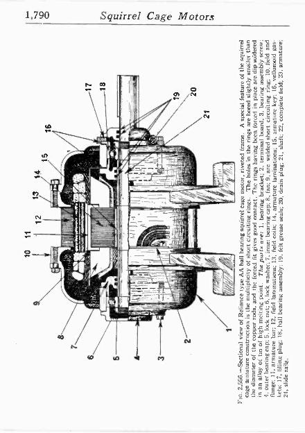
FIG
. 2,
556.
-Sec
tiona
l vi
ew o
f R
elia
nce
type
AA
bal
l be
arin
g sq
uirr
el c
age
mot
or,
rivet
ed f
ram
e.
A s
peci
al f
eatu
re o
f th
e sq
uirr
el
cage
arm
atur
e co
nstr
uctio
n is
th
e m
ultip
licity
of
shor
t ci
rcui
ting
rings
. T
he h
oles
in
the
rings
are
bor
ed s
light
ly s
mal
ler
than
th
e di
amet
er o
f th
e co
pper
rod
s, a
nd
the
forc
ed f
it gi
ves
good
con
tact
. T
he r
ings
hav
ing
been
fo
rced
in
plac
e ar
e di
p so
lder
ed
in a
n al
loy
of t
in o
f hi
gh m
eltin
g po
int.
The
par
ts a
re:
1, b
earin
g br
acke
t; 2,
ter
min
al b
oard
; 3,
bea
ring
asse
mbl
y sc
rew
; 4,
out
er b
earin
g ca
p; 5
, lo
ck n
ut;
6. l
ock
was
her;
7,
inne
r be
arin
g ca
p; 8
. fa
n; 9
, ar
c w
elde
d sh
ort
circ
uitin
g rin
g;
10,
field
an
d fla
nge;
11.
arm
atur
e ba
r; 1
2, f
ield
la
min
atio
ns;
13,
field
coi
ls;
14.
arm
atur
e la
min
atio
ns; 1
5.
arm
atur
e ke
y; 1
6, v
ellu
moi
d ga
s-
kets
; 17
, fil
ling
plug
; 18
, ba
ll be
arin
g as
sem
bly;
19
, fe
lt gr
ease
sea
ls;
20,
drai
n pl
ug;
21,
shaf
t; 22
. co
mpl
ete
field
; 23,
arm
atur
e;
24,
slid
e ra
ils.
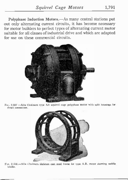
Squirrel Cage Motors 1,791
Polyphase Induction Motors.-As many central stations put out only alternating current circuits, it has become necessary for motor builders to perfect types of alternating current motor suitable for all classes of industrial drive and which are adapted for use on these commercial circuits.
lrtf Y ,
rr \ 11 ,
o
---w,.. ,,11
. . .Sr..
ps tili- .-.&.r L oYr.o, ,ee .o
1 `r. :..,' ±,.
.,t . l l',."' .-¡r ...¡...--,-;4, . i<, . 1 .
:.
` .
.yt :. ,t._, ;w :: ' >''.t"J, ..'..
ee
. ' . j
^°. f ' 1 _ \
Fic. 2.557 -Allis Chalmers type AR squirrel cage polyphase motor with split housings for direct connection.
o::'. -
Fro. 2,558.-Allis Chalmers skeleton cast steel frame for type A.R. motor showing saddle blocks.
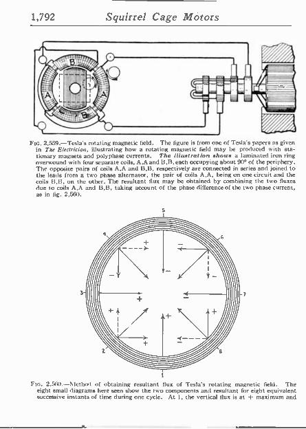
1,792 Squirrel Cage Motors
FIG. 2,559.-Tesla's rotating magnetic field. The figure is from one of Teslá s papers as given in The Electrician, illustrating how a rotating magnetic field may be produced with sta- tionary magnets and polyphase currents. The illustration shows a laminated iron ring overwound with four separate coils, A,A and 13,B, each occupying about 90° of the periphery. The opposite pairs of coils A,A and B,B.-respectively are connected in series and joined to the leads from a two phase alternator, the pair of coils A,A, being on one circuit and the coils 13.13, on the other. The resultant flux may be obtained by combining the two fluxes due to coils A,A and B,B, taking account of the phase difference of the two phase current, as in fig. 2,560.
FIG. 2,560-Method of obtaining resultant flux of Testa's rotating magnetic field. The eight small diagrams here seen show the two components and resultant for eight equivalent successive instants of time during one cycle. At 1, the vertical flux is at -r maximum and
Squirrel Cage Motors 1,793
In regard to polyphase motors it should be noted that for given requirements of load and voltage, the amount of copper required in the distributing system is less. On account of the saving in copper three phase motors are preferal le to two phase wherever service conditions will permit.
The construction of an induction motor is very simple, and since there are no sliding contacts as with commutator motors, there can he no sparks during operation-a feature which adapts the motor for use in places where fire hazards are prominent.
The motor consists, as already mentioned, simply of two parts: an armature and Meld magnets, without any electrical con- nection between these parts. Its operation depends upon:
1. The production of a rotating magnetic field;
2. Induction of eddy currents in the armature;
3. Reaction between the rotating magnetic field and the eddy currents.
Fta. 2,560.-Text continued.
the horizontal is zero. At 2, the vertical flux is still + but decreasing, and the hor¢ontal is + and increasing, the resultant is the thick line sloping at 45° upward to the right. At 3, the vertical flux is zero, and the horizontal is at its + maximum, and similarly for the other diagrams. Thus at 8, the vertical flux is + and increasing, while the horizontal is - and decreasing, the resultant is the thick line sloping at 45° upward to the left. At points 2, 4, 6, and 8 the increasing (luxes are denoted by full, and the decreasing by dotted lines. The laminated iron of the ring is indicated by the circles, and the result is that at the instants chosen the flux across the plane of the ring is directed inward from the points 1, 2, 3, 4, etc., on the inner periphery of the iron. There will, therefore, appear successively at these points effective north poles, the corresponding south poles being simul- taneously developed at the points diametrically opposite. These poles travel continu- ously from one position to the next, and thus the magnetic flux across the plane of the ring swings round and round, completing a revolution without change of intensity during the cycle time of the current.
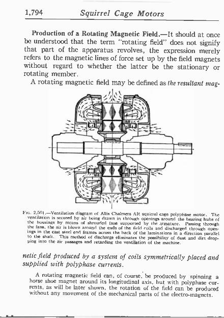
1,794 Squirrel Cage Motors
Production of a Rotating Magnetic Field.-It should at once be understood that the term "rotating field" does not signify that part of the apparatus revolves, the expression merely refers to the magnetic lines of force set up by the field magnets without regard to whether the latter be the stationary or rotating member.
A rotating magnetic field may be defined as the resultant mag-
h
FIG. 2.561.-Ventilation diagram of Allis Chalmers AR squirrel cage polyphase motor. The ventilation is secured by air being drawn in through openings around the hearing hubs of the housings by means of shrouded fans supported by the armature. Passing through the fans. the air is blown around the ends of the field coils and discharged through open- ings in the cast steel end frames across the back of the laminations in a direction parallel to the shaft. This method of discharge eliminates the possibility of dust and dirt drop- ping into the air passages and retarding the ventilation of the machine.
nelic field produced by a system of coils symmetrically placed and supplied with polyphase currents.
A rotating magnetic field can, of course, be produced by spinning a horse shoe magnet around its longitudinal axis, but with polyphase cur- rents, as will be later shown, the rotation of the field can be produced without any movement of the mechanical parts of the electro -magnets.
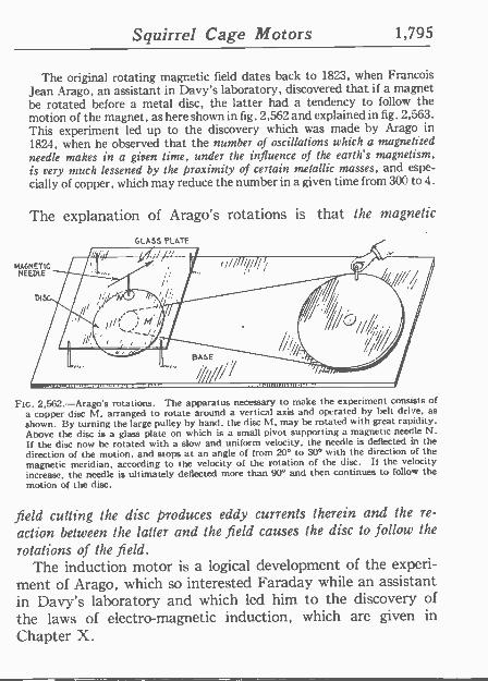
Squirrel Cage Motors 1,795
The original rotating magnetic field dates back to 1823, when Francois Jean Arago, an assistant in Davy's laboratory, discovered that if a magnet he rotated before a metal disc, the latter had a tendency to follow the motion of the magnet, as here shown in fig. 2,562 and explained in fig. 2,563. This experiment led up to the discovery which was made by Arago in 1824, when he observed that the number of oscillations which a magnetized needle makes in a given lime, under the influence of the earth's magnetism, is very much lessened by the proximity of certain metallic masses, and espe- cially of copper, which may reduce the number in a given time from 300 to 4.
The explanation of Arago's rotations is that the magnetic
MAGNETIC NEEDLE
GLASS PLATE
//,
FIG. 2,562.-Arago's rotations. The apparatus necessary to make the experiment consists of a copper disc M, arranged to rotate around a vertical axis and operated by belt drive, as
shown. By turning the large pulley by hand, the disc M. may be rotated with great rapidity. Above the disc is a glass plate on which is a small pivot supporting a magnetic needle N. If the disc now be rotated with a slow and uniform velocity, the needle is deflected 'm the direction of the motion, and stops at an angle of from 20° to 30° with the direction of the magnetic meridian, according to the velocity of the rotation of the disc. If the velocity increase, the needle is ultimately deflected more than 900 and then continues to follow the
motion of the disc.
field cutting the disc produces eddy currents therein and the re-
action between the latter and the field causes the disc to follow the
rotations of the field. The induction motor is a logical development of the experi-
ment of Arago, which so interested Faraday while an assistant in Davy's laboratory and which led him to the discovery of the laws of electro -magnetic induction, which are given in
Chapter X.
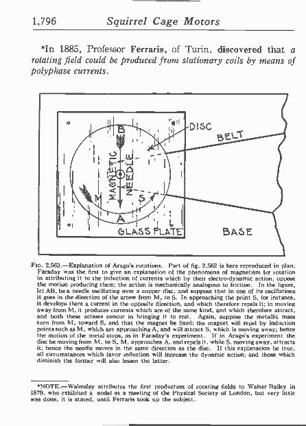
1,796 Squirrel Cage Motors
*In 1885, Professor Ferraris, of Turin, discovered that a rotating field could be produced from stationary coils by means of polyphase currents.
Ftc. 2.563.-Explanation of Arago's rotations. Part of fig. 2,562 is here reproduced in plan. Faraday was the first to give an explanation of the phenomena of magnetism by rotation in attributing it to the induction of currents which by their electro -dynamic action, oppose the motion producing them; the action is mechanically analogous to friction. In the figure, let AB, be a needle oscillating over a copper disc, and suppose that in one of its oscillations it goes in the direction of the arrow from M, to S. In approaching the point S, for instance. it develops there a current in the opposite direction, and which therefore repels it; in moving away from M. it produces currents which are of the same kind, and which therefore attract, and both these actions concur in bringing it to rest. Again, suppose the metallic mass turn from M, toward S, and that the magnet be fixed; the magnet will repel by induction points such as M, which are approaching A, and will attract S, which is moving away; hence the motion of the metal stops, as in Faraday's experiment. If in Arago's experiment the disc be moving from hl, to S, M, approaches A, and repels it, while S, moving away, attracts it; hence the needle moves in the same direction as the disc. If this explanation be true, all circumstances which favor induction will increase the dynamic action; and those which diminish the former will also lessen the latter.
'NOTE.-Walmsley attributes the first production of rotating fields to Walter Bailey in 1879. who exhibited a nodel at a meeting of the Physical Society of London, but very little was done, it is stated, until Ferraris took up the subject.
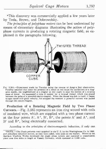
Squirrel Cage Motors 1,797
*This discovery was commercially applied a few years later by Tesla, Brown, and Dobrowolsky.
The principles of polyphase motors can be best understood by means of elementary diagrams illustrating the action of poly- phase currents in producing a rotating magnetic field, as ex- plained. in the paragraphs following.
COPPER CUBE
TWISTED THREAD
19) FIG. 2,564.-Experiment made by Faraday being the reverse of Arago's first observation.
Faraday assumed that since the presence of a metal at rest stops the oscillations of a mag- netic needle, the neighborhood of a magnet at rest ought to stop the motion of a ro'ating mass of metal. He suspended a cube of copper by a twisted thread, which was placed between the poles of a powerful electro -magnet. When the thread was left to itself, it began to spin round with great velocity, but stopped the moment a powerful current was passed through the electro -magnet.
Production of a Rotating Magnetic Field by Two Phase Currents.-Fig. 2,565 represents an iron ring wound with coils of insulated wire, which are supplied with a two phase current at the four points A', A", B', B", the points A' and A", and B' and B", being electrically connected.
According to the principles of electro -magnetic induction, if only one
*NOTE.-The Testa patents were acquired in the U. S. by the Westinghouse Co. in 1888, and polyphase induction motors, as they were called, were soon on the market. Brown of the Derlikon Machine Works developed the single phase system and operated a transmission plant over five miles in length at Kassel, Germany, which operated at 2,000 volts.
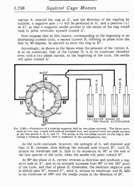
1,798 Squirrel Cage Motors
current A, entered the ring at A', and the direction of the winding be suitable, a negative pole (-) will be produced at A', and a positive (-I-) at A", so that a magnetic needle pivoted in the center of the ring would tend to point vertically upward toward A'.
Now suppose that at this instant, corresponding to the beginning of an alternating current cycle, a second current B, differing in phase from the first by 90 degrees, be allowed to enter the ring at B".
Accordingly, as shown in the figure when the pressure of the current A, is at its maximum, that of the current B, is at its minimum; therefore even with a two phase current, at the beginning of the cycle, the needle will point toward A'.
360'-0°
W 11)
4 _ a
e
M COLLECTOR RINGS OF
TWO PHASE ALTERNATOR 180°
FIG. 2.565.-Production of a rotating magnetic field by two phase currents. The figure repre- sents an iron ring, wound with coils of insulated wire, and supplied with two phase currents at the four points A. B, C, and D. The action of the two phase current on the ring in pro- ducing a rotating magnetic field is explained in the accompanying text.
As the cycle continues, however, the strength of A, will diminish and that of B, increase, thus shifting the induced pole toward B", until B, attains its maximum and A, falls to its minimum at 90° or the end of the first quarter of the cycle, when the needle will point toward W.
At 90° the phase of A, current reverses in direction and produces a neg- ative pole at A", and as its strength increases from 90° to the 180° point of the cycle, and that of phase B, diminishes, the resultant negative pole is shifted past B", toward A", until A, attains its maximum and B, falls to its minimum at 180° and the needle points in the direction of B".
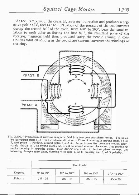
Squirrel Cage Motors 1,799
At the 180° point of the cycle, B, reverses in direction and produces a neg- ative pole at B', and as the fluctuation of the pressure of the two currents during the second half of the cycle, from 180° to 360°, bear the same re- lation to each other as during the first half, the resultant poles of the rotating magnetic field thus produced carry the needle around in con- tinuous rotation so long as the two phase current traverses the windings of the ring.
Ftc. 2,566.-Production of rotating magnetic field in a two pole two phase motor. The poles are numbered from 1 to 4 in a clockwise direction. Phase A winding is around poles 1 and 3, and phase 11 winding, around poles 2 and 4. In each case the poles are wound alter- nately, that is, if 1 be wound clockwise, 3 will be wound counter clockwise, thus producing unlike polarity in opposite poles. Now during one cycle of the two phase current, the following changes take place, starting with pole 1, of N polarity and 3, of S polarity.
One Cycle
Degrees 0° to 90° 90° to 180° 180 to 270° 270° to 360°
Polarity IN - 3S 2N -4S 3N -IS 4N -2S
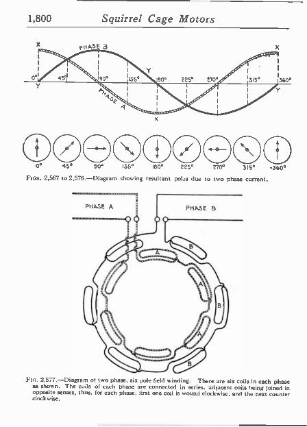
1,800 Squirrel Cage Motors
x
0° 45° 50° 135° 150° 225° 270° 315° -360°
FI:GS. 2,567 to 2,576.-Diagram showing resultant pops due to two phase current.
FIG. 2.577.-Diagram of two phase, six pole field winding. There are six coils in each phase as shown. The coils of each phase are connected in series, adjacent coils tieing joined in opposite senses, thus, for each phase, first one coil is wound clockwise, and the next counter clockwise.
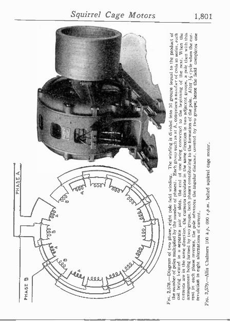
PH
AS
E
B
PH
AS
E A
1
°',
e `{
I
a: t
fiFt
, r`
p i
: ,1
-
1
t /I
J.
. Y
k' ,
, J
¡,i
1 .. .
+ lJ
J
Ftc.
2,5
78.-
Dia
gram
of
two
phas
e, e
ight
po
le f
ield
w
indi
ng.
The
win
ding
is
divi
ded
into
16
grou
ps
(equ
al to
the
pro
duct
of
th
e nu
mbe
r of
pol
es m
ultip
lied
by t
he n
umbe
r of
pha
ses)
. E
ach
grou
p su
ch a
s at
A,
com
pris
es a
nu
mbe
r of
coi
ls i
n se
ries,
eac
h co
il be
ing
loca
ted
in a
se
para
te
)air
of s
lots
, th
e en
d of
on
e be
ing
conn
ecte
d to
th
e be
ginn
ing
of t
he
next
. W
hen
the
curr
ents
arc
in
the
sam
e di
rect
ion,
the
cur
rent
s ci
rcul
ate
in t
he s
ame
dire
ctio
n in
tw
o ad
jace
nt g
roup
s, a
pol
e th
en w
ith t
his
arra
ngem
ent
bein
g fo
rmed
by
tw
o gr
oups
, bo
th p
hase
s co
ntrib
utin
g to
the
form
atio
n of
the
pol
e.
Afte
r }I
cyc
le w
hen
the
cur-
re
nt in
ea
ch p
hase
rev
erse
s, t
he p
ole
adva
nces
the
ang
ular
dis
tanc
e, c
over
ed b
y tw
o gr
oups
; he
nce
the
field
co
mpl
etes
on
e re
volu
tion
in
eigh
t al
tern
atio
ns o
f cu
rren
t.
FIG
. 2,
579.
-Alli
s C
halm
ers
100
h.p.
69
0 r.
p.m
. be
lted
squi
rrel
cag
e m
otor
.
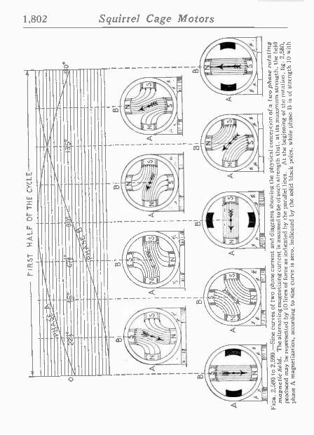
- t
-46°
67
I
+-
FIR
ST
H
ALF
O
F T
HE
CY
CLE
- B
I
A
B
n11l
llf
llpll(
I f
B!
FIG
S.
2,58
0 to
2,5
99.-
Sin
e cu
rves
of
two
phas
e cu
rren
t an
d di
agra
ms
show
ing
the
phys
ical
con
cept
ion
of a
t t
oo p
hase
rot
atin
g m
agne
tic fi
eld.
T
he a
ltern
atin
g m
agne
tizin
g cu
rren
t is
ass
umed
to
be o
f suc
h st
reng
th t
hat,
at it
s m
axim
um s
tren
gth,
the
fie
ld
prod
uced
may
be
repr
esen
ted
by 1
0 lin
es o
f fo
rce
as in
dica
ted
by t
he p
aral
lel
lines
. A
t th
e be
ginn
ing
of t
he r
otat
ion,
fig
. 2.
580.
phas
e A
mag
netiz
atio
n, a
ccor
ding
to s
ine
curv
e is
zer
o, i
ndic
ated
by
the
solid
bl
ack
pole
s, w
hile
pha
se
B i
s of
str
engt
h 10
with

SE
CO
ND
H
ALF
OF
TH
E
CY
CLE
-1
FIII
r II
IfII
I
IA
1111
1111
11
11
3G0°
FIG
S.
2,58
0 to
2,5
99.-
Tex
t co
ntin
ued.
cu
rren
t in
the
dire
ctio
n to
pro
duce
a s
outh
pol
e at
B.
Sim
ilarl
y, i
n fi
g. 2
,531
, th
e st
reng
th o
f A
is
4 In
es,
and
of B
. 9
Tin
es.
the
resu
ltant
mag
netiz
atio
n ha
ving
rota
ted
2255
°.
The
dir
ectio
n of
the
res
ulta
nt m
agne
tizat
ion
is in
dica
ted
by t
he a
rrow
in
each
fi
gure
. It
sho
uld
be n
oted
in
fig.
2,5
86, th
at t
he p
olar
ity o
f B
is
reve
rsed
, the
cur
rent
cur
ve n
ow b
eing
abo
ve t
he z
ero
line.
B
y fo
llow
ing
the
arro
w t
hrou
gh t
he s
ucce
ssiv
e po
sitio
ns t
he r
otat
ion
of t
he r
esul
tant
mag
netiz
atio
n is
cle
arly
see
n.
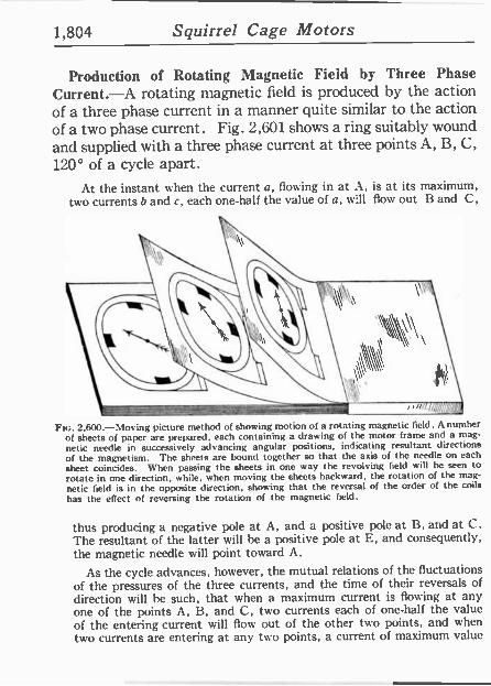
1,804 Squirrel Cage Motors
Production of Rotating Magnetic Field by Three Phase Current.-A rotating magnetic field is produced by the action of a three phase current in a manner quite similar to the action of a two phase current. Fig. 2,601 shows a ring suitably wound and supplied with a three phase current at three points A, B, C, 120° of a cycle apart.
At the instant when the current a, flowing in at A, is at its maximum, two currents b and c, each one-half the value of a, will flow out B and C,
FIG. 2,600.-Moving picture method of showing motion of a rotating magnetic field. A number of sheets of paper are prepared, each containing a drawing of the motor frame and a mag-
netic needle in successively advancing angular positions, indicating resultant directions of the magnetism. The sheets are bound together so that the axis of the needle on each
sheet coincides. when passing the sheets in one way the revolving field will he seen to
rotate in one direction, while, when moving the sheets backward, the rotation of the mag-
netic field is in the opposite direction, showing that the reversal of the order of the coils
has the effect of reversing the rotation of the magnetic field.
thus producing a negative pole at A, and a positive pole at B, and at C. The resultant of the latter will be a positive pole at E, and consequently, the magnetic needle will point toward A.
As the cycle advances, however, the mutual relations of the fluctuations of the pressures of the three currents, and the time of their reversals of direction will he such, that when a maximum current is flowing at any one of the points A, B, and C, two currents each of one-half the value of the entering current will flow out of the other two points, and when two currents are entering at any two points, a current of maximum value
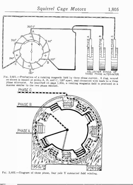
Squirrel Cage Motors 1,805
E COLLECTOR RINGS OF 180° THREE PHASE ALTERNATOR FIG. 2,601.-Production of a rotating magnetic field by three phase current. A ring, wound
as shown is tapped at points A. B. and C, 120° apart, and connected with leads to a three phase alternator. As described on page 1,804, a rotating magnetic field is produced in a manner similar to the two phase method.
PHASE C
FIG. 2,602.-Diagram of three phase, four pole Y connected field winding.
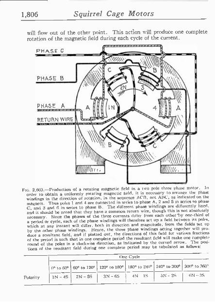
1,806 Squirrel Cage Motors
will flow out of the other point. This action will produce one complete rotation of the magnetic field during each cycle of the current.
PHASE C
PHASE B
PHASE A
RETURN WIRE
Ftc. 2,603.-Production of a rotating magnetic field in a two pole three phase motor. In
order to obtain a uniformly rotating magnetic field, it is necessary to arrange the phase
windings in the direction of rotation, in the sequence ACB, not ABC, as indicated on the magnets. Thus poles 1 and 4 are connected in series to phase A, 2 and 5 in series to phase
C. and 3 and 6 in series to phase B. The different phase windings are differently lined.
and it should be noted that they have a common return wire, though this is not absolutely necessary. Since the phases of the three currents differ from each other 'by one-third of
a period or cycle, each of the phase windings will therefore set up a field between its pokes,
which at any instant will differ, both in direction and magnitude, from the fields set up
by the other phase windings. Hence, the three phase windings acting together will pro-
duce a resultant field, and if plotted out, the directions of this field for various fractions
of the period is such that in one complete period the resultant field will make one complete
round of the poles in a clockwise direction, as indicated by the curved arrow. The posi-
tions of the resultant field during one complete period may be tabulated as follows:
Polarity
One Cycle
0° to 60° 60° to 120° 120° to 180° 180° to 240° 240° to 300° 300° to 360°
1N -4S 2N -5S 3N -6S 4N - IS 5N - 2S 6N -3S
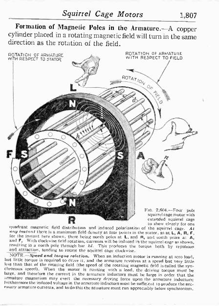
Squirrel Cage Motors 1,807
Formation of Magnetic Poles in the Armature.-A copper cylinder placed in a rotating magnetic field will turn in the same direction as the rotation of the field.
ROTATION OF ARMATURE WITH RESPECT TO STATOR
ROTATION OF ARMATURE WITH RESPECT TO FIELD
wy r,. FIG. 2,604.-Four pole 0` -?`"¡1°..- "'' ̂r i ' squirrel cage motor with 1:' t
ª extended squirrel cage to show clearly for one
quadrant magnetic field distribution and induced polarization of the squirrel cage. At any instant there is a maximum field density at four points in the stator, as at L, A, R, F, for the instant here shown, there being north poles at L, and R, and south poles at A, and F, With clockwise field rotation. currents will be induced in the squirrel cage as shown, resulting in a north pole through bar hd. This produces the torque both by repulsion and attraction, tending to rotate the squirrel cage clockwise. NOTE.-Speed and torque relation. When an induction motor is running at zero load, but little torque is required to drive it, and the armature revolves at a speed but very little
less than that of the rotating field (the speed of the rotating magnetic field is called the syn- chronous speed). When the motor is running with a load, the driving torque must be luge, and therefore the current in the armature inductors must be large in order that the armature magnetism may exert the necessary driving force upon the armature inductors; furthermore the induced voltage in the armature inductors must he sufficient to produce the nec- essary armature currents, and to do this the armature must run appreciably below synchronism.
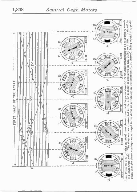
FIR
ST
H
ALF
O
F
TH
E
CY
CLE
B
II tif
f ` tr
uilt
nos.
2,6
05
to 2
,62.
1.-S
ine
curv
es o
f th
ree
phas
e cu
rren
t an
d di
agra
ms
show
ing
the
phys
ical
con
cept
ion
of a
th
ree
phas
e ro
tat-
ing
mag
netic
fie
ld.
The
dia
gram
s ar
e co
nstr
ucte
d in
the
sam
e m
anne
r as
exp
lain
ed i
n fig
s. 2
,580
to
2,59
9.
It sh
ould
be
note
d th
at t
he p
hase
win
ding
s ar
e ar
rang
ed i
n th
e di
rect
ion
of r
otat
ion
in t
he s
eque
nce
AC
B,
phas
e C
, be
ing
wou
nd i
n op
posi
te
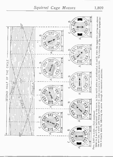
SE
CO
ND
H
ALF
O
F
TH
E
CY
CLE
A
3 0°
FIG
S.
2,60
5 to
2.6
24 .-
Tes
t co
ntin
ued.
se
nse
to A
and
It,
as
indi
cate
d by
the
cur
ve,
in t
hat
nort
h po
les
arc
prod
uced
at
A a
nd B
. w
hen
the
resp
ectiv
e cu
rves
are
abo
ve
the
zero
lin
e, a
sou
th
pole
bei
ng p
rodu
ced
at C
. w
hen
its c
urve
is
abov
e th
e ze
ro l
ine.
T
he r
otat
ion
o( t
he re
sulta
nt m
agne
tiza-
tio
n is
cle
arly
see
n by
fol
low
ing
the
arro
w
thro
ugh
its s
ucce
ssiv
e po
sitio
ns.
-00
CD
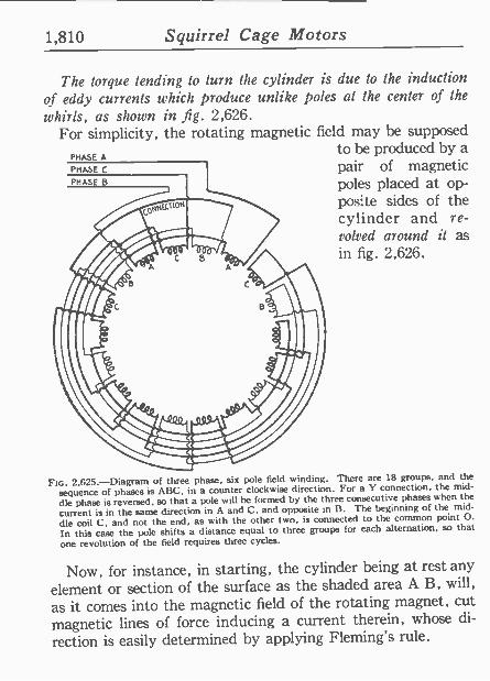
1,810 Squirrel Cage Motors
The torque tending to turn the cylinder is due to the induction of eddy currents which, produce unlike poles al the center of the
whirls, as shown in fig. 2,626. For simplicity, the rotating magnetic field may be supposed
to be produced by a pair of magnetic poles placed at op- posite sides of the cylinder and re- volved around it as in fig. 2,626.
PHASE A
Ftc. 2,625.-Diagram of three phase, six pole field winding. There are 18 groups, and the
sequence of phases is ABC, in a counter clockwise direction. For a Y connection, the mid-
dle phase is reversed, so that a pole will he formed by the three consecutive phases when the
current is in the same direction in A and C. and opposite in B. The beginning of the mid-
dle coil C, and not the end, as ssith the other two, ís connected to the common point O.
In this case the pole shifts a distance equal to three groups for each alternation, so that
one revolution of the field requires three cycles.
Now, for instance, in starting, the cylinder being at rest any
element or section of the surface as the shaded area A B, will,
as ít comes into the magnetic field of the rotating magnet, cut
magnetic lines of force inducing a current therein, whose di-
rection is easily determined by applying Fleming's rule.
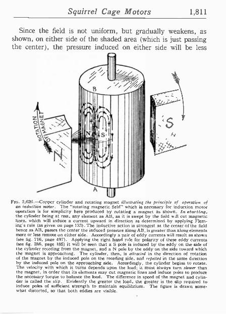
Squirrel Cage Motors 1,811
Since the field is not uniform, but gradually weakens, as shown, on either side of the shaded area (which is just passing the center), the pressure induced on either side will be less
Ftm. 2,626.-Copper cylinder and rotating magnet illustrating the principle of operation of an induction ,rotor. The "rotating magnetic field" which is necessary for induction motor operation is for simplicity here produced by rotating a magnet as shown. In starting, the cylinder being at rest, any element as AB. as it is swept by the field will cut magnetic lines, which will induce a current upward in direction as determined by applying Flem- ing's rule (as given on page 133). The inductive action is strongest at the center of the field hence as AB, passes the center the induced pressure along AB, is greater than along elements more or less remote on either side. Accordingly a pair of eddy currents will result as shown (see fig. 716. page 497). Applying the right hand rule for polarity of these eddy currents (see fig. 286, page 185) it will be seen that a S pole is induced by the eddy on the side of the cylinder receding from the magnet, and a N pole by the eddy on the side toward which the magnet is approaching. The cylinder, then, is attracted in the direction of rotation of the magnet by the induced pole on the receding side, and repelled in the same direction by the induced pole on the approaching side. Accordingly, the cylinder begins to rotate. The velocity with which it turns depends upon the load; it must always turn slower than the magnet, in order that its elements may cut magnetic lines and induce poles to produce the necessary torque to balance the load. The difference in speed of the magnet and cylin- der is called the slip. Evidently the greater the load, the greater is the slip required to induce poles of sufficient strength to maintain equilibrium. The figure is drawn some- what distorted, so that both eddies are visible.
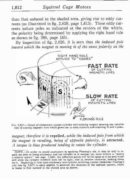
1,812 Squirrel Cage Motors
than that induced in the shaded area, giving rise to eddy cur- rents (as illustrated in fig. 2,628, page 1,813). These eddy cur- rents induce poles as indicated at the centers of the whirls, the polarity being determined by applying the right hand rule as shown in fig. 286, page 185).
By inspection of fig. 2,626, it is seen that the induced pole toward which the magnet is moving is of the saute polarity as the
RIGHT HAND RULE APPLIED TO ''EDDIES"
FAST RATE OF CUTTING
MAGNETIC LINES
SLOW RATE OF CUTTING
MAGNETIC LINES
- r
FLEMINGS RULE
FIG. 2,627.-Detail of elementary copper cylinder and rotating magnet showing the variable rate of cutting magnetic lines which gives rise to eddy currents and resulting N and S poles.
magnet; therefore it is repelled, while the induced pole from which
the magnet is receding, being of opposite polarity, is attracted. A torque is thus produced tending to rotate the cylinder.
NOTE.-In order to ovoid confusion in applying Fleming's rule, it may he well to re- gard the pole as being stationary and the cylinder as in motion; for, since motion is "purely a relative matter" (see page. 1,556), the inductive action will be the same as if the pole stood still while the cylinder revolved from left to right, that is, counter clockwise, looking down on it. Regarding it thus (pole stationary and cylinder revolving counter clockwise) Fleming's rule (see fig. 2,627) is easily applied to ascertain the direction of the induced current, which is found to flow upward in the shaded area as shown.
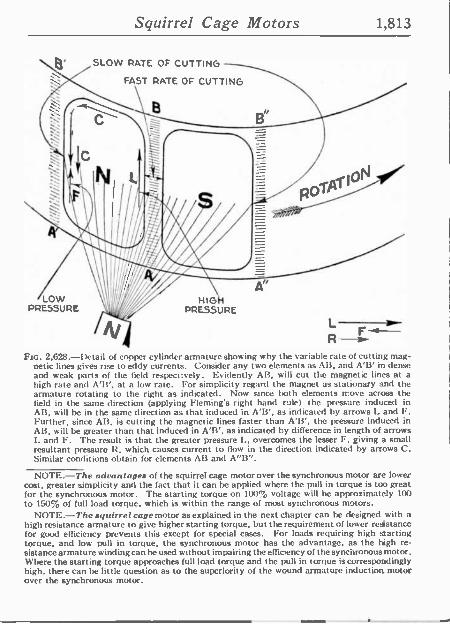
Squirrel Cage Motors 1,813
SLOW RATE OF CUTTING
FAST RATE OF CUTTING
6
LOW PRESSURE
HIG PRESSURE
Ftc. 2,628.-I)etail of copper cylinder armature shoeing why the variable rate of cutting mag- netic lines gives rise to eddy currents. Consider any two elements as AB, and A'B' in dense and weak parts of the field respectively. Evidently AB, will cut the magnetic lines at a high rate and A'B', at a low rate. For simplicity regard the magnet as stationary and the armature rotating to the right as indicated. Now since both elements move across the field in the same direction (applying Fleming s right hand rule) the pressure induced in AB, will be in the same direction as that induced in A'B', as indicated by arrows L and F. Further, since AB, is cutting the magnetic lines faster than A'B', the pressure induced in AB, will be greater than that induced in A'B', as indicated by difference in length of arrows L and F. The result is that the greater pressure L, overcomes the lesser F, giving a small resultant pressure R, which causes current to flow in the direction indicates by arrows C. Similar conditions obtain for elements AB and A"B".
NOTE.-The advantages of the squirrel cage motor over the synchronous motor are lower cost, greater simplicity and the fact that it can be applied where the pull in torque is too great for the synchronous motor. The starting torque on 100% voltage will be approximately 100 to 150% of full load torque, which is within the range of most synchronous motors.
NOTE.-The squirrel cage motor as explained in the next chapter can be designed with a high resistance armature to give higher starting torque, but the requirement of lower resistance for good efficiency prevents this except for special cases. For loads requiring high starting torque, and low pull in torque, the synchronous motor has the advantage, as the high re- sistance armature winding can he used without impairing the efficiency of the synchronous motor. Where the starting torque approaches full load torque and the pull in torque is correspondingly high, there can be little question as to the superiority of the wound armature induction motor over the synchronous motor.
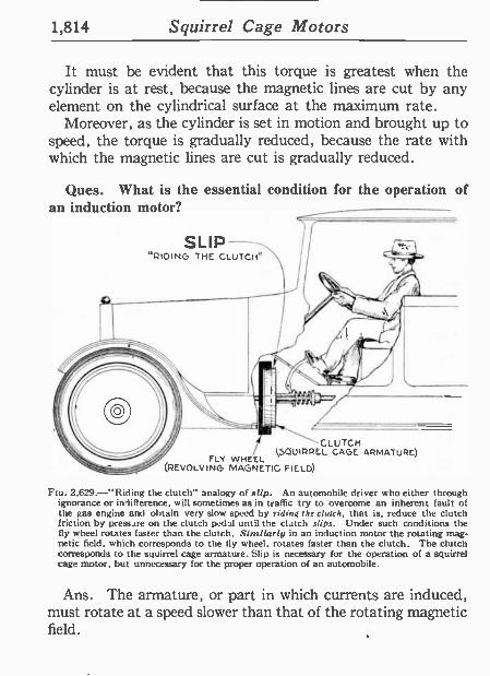
1,814 Squirrel Cage Motors
It must be evident that this torque is greatest when the cylinder is at rest, because the magnetic lines are cut by any element on the cylindrical surface at the maximum rate.
Moreover, as the cylinder is set in motion and brought up to speed, the torque is gradually reduced, because the rate with which the magnetic lines are cut is gradually reduced.
Ques. What is the essential condition for the operation of an induction motor?
SLIP "RIDING THE CLUTCH"
4 CLUTCH .1,5QUIRREL CAGE ARMATURE)
FLY WHEEL (REVOLVING MAGNETIC FIELD)
Fto. 2,629.-"Riding the clutch" analogy of slip. An automobile driver who either through ignorance or inliflerence, will sometimes as in traffic try to overcome an inherent fault of the gas engine and obtain very slow speed by riding the clutch, that is, reduce the clutch friction by pressure on the clutch pedal until the clutch slips. Under such conditions the fly wheel rotates faster than the clutch. Simi/aril/ in an induction motor the rotating mag- netic field, which corresponds to the fly wheel, rotates faster than the clutch. The clutch corresponds to the squirrel cage armature. Slip is necessary for the operation of a squirrel cage motor, but unnecessary for the proper operation of an automobile.
Ans. The armature, or part in which currents are induced, must rotate at a speed slower than that of the rotating magnetic field.
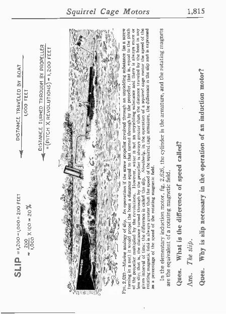
y-
; e
--,!
._.,,
:t.,''
'---,
.."-_
____
.,.__
____
. ,^
!% t
_ -
iS
-.--
- #
t .
-1 S í
- r _
_ T
Z-3
. --
.7-.
. 1W
-:=
, ^ fit
'/ }_
_ :\
-s,.
FIG
. 2,
630.
-Mar
ine
anal
ogy
of s
lip.
In o
pera
tion
if th
e sc
rew
pro
pelle
r re
volv
ed t
hrou
gh a
n un
yiel
ding
sub
stan
ce (
as a
scr
ew
turn
ing
in a
nut
) it
wou
ld p
rope
l th
e bo
at a
di
stan
ce e
qual
to
that
tur
ned
thro
ugh
by
the
prop
elle
r, t
hat
is, eq
ual
to t
he p
itch
of t
he
prop
elle
r m
ultip
lied
by t
he r
evol
utio
ns.
Ilow
ever
, w
ater
is
not
an
unyi
eldi
ng s
ubst
ance
and
the
re
is
alw
ays
mor
e or
le
ss s
lip;
that
is,
the
dis
tanc
e tu
rned
thr
ough
by
the
prop
elle
r is
alw
ays
grea
ter
than
th
e di
stan
ce t
rave
led
by t
he b
oat
in
any
give
n in
terv
al o
f tim
e; t
he d
iffer
ence
is
cal
led
the
slip
. S
' 'ta
rty,
in
the
oper
atio
n of
a s
quirr
el c
age
mot
or t
he
spee
d of
the
rota
ting
mag
netic
fie
ld i
s al
way
s gr
eate
r th
an t
he s
peed
of
the
squi
rrel
cag
e ar
mat
ure,
the
diff
eren
ce is
the
slip
and
is
expr
esse
d as
a
perc
enta
ge o
f th
e sp
eed
of t
he r
otat
ing
mag
netic
fie
ld.
In t
he e
lem
enta
ry i
nduc
tion
mot
or,
fig,
2,6
26,
the
cylin
der
is t
he a
rmat
ure,
and
the
rot
atin
g m
agne
ts
are
the
equi
vale
nt o
f a
rota
ting
mag
netic
fie
ld.
Que
s.
Wha
t is
the
dif
fere
nce
of s
peed
cal
led?
Ans
. T
he s
lip.
Que
s.
Why
is
slip
nec
essa
ry i
n th
e op
erat
ion
of a
n in
duct
ion
mot
or?
SLIP
= 4
,200
-1,0
00=
200
FE
ET
200
I 00
0 X
10
0 =
20
%
=
MC
RW
O
" ,(
71^z
ofi
.
DIS
TA
NC
E T
RA
VE
LED
B
Y
BO
AT
1,
000
FE
ET
DISTANCE TURNED THROUGH BY PROPELLER
={P
ITC
H
X R
EV
OLU
TIO
NS
) =
1,2
00 F
EE
T
3=
, ->
-.,
_ - .
_
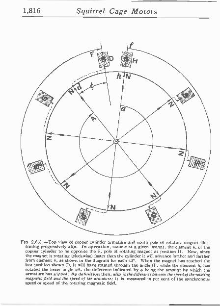
1,816 Squirrel Cage Motors
Fro 2.631.-Top view of copper cylinder armature and south pole of rotating magnet illus- trating progressively slip. In operation, assume at a given instant, the element h, of the copper cylinder to be opposite the ti, pole of rotating magnet at position H. Now, since the magnet is rotating (clockwise) faster than the cylinder it will advance farther and farther from element h, as shown in the diagram for each 45°. When the magnet has reached the last position shown D, it will have rotated through the angle fr, while the element h, has rotated the lesser angle aA, the difference indicated by 4, being the amount by which the armature has slipped. lly definition then, slip is the difference between the speed of the rotating magnetic field and the speed of the armature; it is measured in per cent of the synchronous speed or speed of the rotating magnetic field.
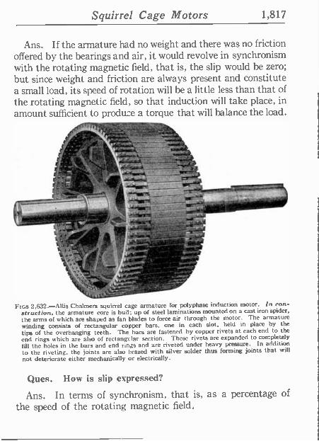
Squirrel Cage Motors 1,817
Ans. If the armature had no weight and there was no friction offered by the bearings and air, it would revolve in synchronism with the rotating magnetic field, that is, the slip would be zero; but since weight and friction are always present and constitute a small load, its speed of rotation will be a little less than that of the rotating magnetic field, so that induction will take place, in amount sufficient to produce a torque that will balance the load.
lvvsr r
r
S. ,` ,
FIGS 2,(132.-Allis Chalmers squirrel cage armature for polyphase induction motor. In con- struction, the armature core is buil: up of steel laminations mounted on a cast iron spider,
the arms of which are shaped as fan blades to force air through the motor. The armature winding consists of rectangular copper bars, one in each slot, held in place by the tips of the overhanging teeth. The bars are fastened by copper rivets at each end to the
end rings which are also of rectangtlar section. These rivets are expanded to completely
fill the holes in the bars and end rings and are riveted under heavy pressure. In addition to the riveting, the joints are also brazed with silver solder thus forming joints that will not deteriorate either mechanically or electrically.
Ques. How is slip expressed?
Ans. In terms of synchronism, that is, as a percentage of the speed of the rotating magnetic field.
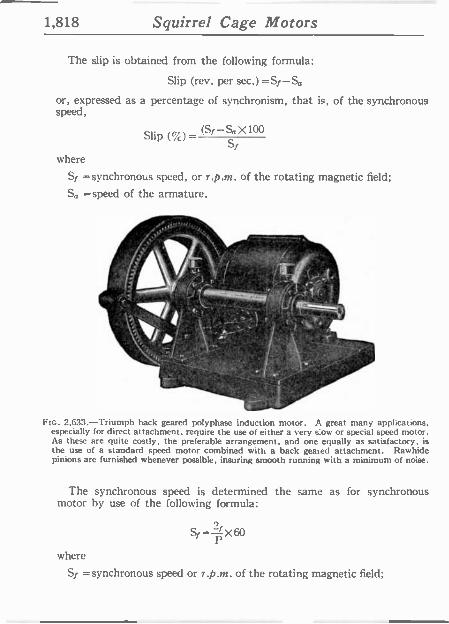
1,818 Squirrel Cage Motors
The slip is obtained from the following formula:
Slip (rev. per sec.) =Si-Sa
or, expressed as a percentage of synchronism, that is, of the synchronous speed,
Slip (%) - (Si-So x100
where
Si =synchronous speed, or r.p.m. of the rotating magnetic field;
So =speed of the armature.
t l ' - " r
o L= FIG. 2,633.-Triumph hack geared polyphase induction motor. A great many applications,
especially for direct attachment, require the use of either a very s:ow or special speed motor. As these are quite costly, the preferable arrangement, and one equally as satisfactory, is the use of a standard speed motor combined with a back geared attachment. Rawhide pinions are furnished whenever possible, insuring smooth running with a minimum of noise.
I ..
The synchronous speed is determined the same as for synchronous motor by use of the following formula:
=- ADO
where
Si =synchronous speed or r.p.m. of the rotating magnetic field;
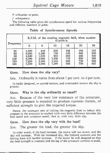
Squirrel Cage Motors 1,819
P =Number of poles; f = frequency. The following table gives the synchronous speed for various frequencies
and different numbers of poles:
Table of Synchronous Speeds
Frequency
R.P.M. of the rotating magnetic field, when number of poles ís
2 6 10 16 20 24
25 1,500 500 300 188 150 125 60 3,600 1,200 720 450 360 300 80 4,800 1,600 960 600 480 400
100 6,000 2,000 1,200 750 600 500 120 7,200 2,400 1,44Q 900 720 600 125 7,500 2,500 1,500 938 750 625
Ques. How does the slip vary?
Ans. Ordinarily it varies from about 1 per cent. to 4 per cent.
In badly designed, or special motors, and overloaded motors the slip is greater.
Ques. Why is the slip ordinarily so small?
Ans. Because of the very low resistance of the armature, very little pressure is required to produce currents therein, of sufficient strength to give the required torque.
Hence, the necessary rate of cutting the magnetic lines to induce this pressure in the armature is reached with very little difference between the field speed and armature speed, that is, with very little slip.
Ques. How does the slip vary with the load?
Ans. The greater the load, the greater the slip.
In other words, if the load increase, the motor will run slower, and the slip will increase. With the increased slip, the induced currents and the driving force will further increase. If the motor be well designed so that the field strength is constant and the lag of the armature currents is small,
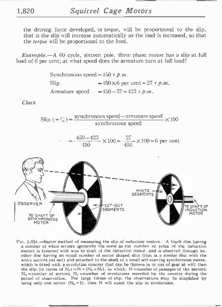
1,820 Squirrel Cage Motors
the driving force developed, or torque, will be proportional to the slip, that is the slip will increase automatically as the load is increased, so that the torque will be proportional to the load.
Example.-A 60 cycle, sixteen pole, three phase motor has a slip at full load of 6 per cent; at what speed does the armature turn at full load?
Check
Synchronous speed=450 r.p.m. Slip =450X6 per cent=27 r.p.m. Armature speed =450-27=423 r.p.m.
Slip (_ %) - synchronous speed -armature speed X100
synchronous speed
OBSERVER
l TO SHAFT OF SY MOTOR OUS
454500-423 X 27 100 = X100 =6 per cent
450
CUT-OUT SEGMENTS
WHITE -=. SEGMENTS
t /
TO SHAFT OF INDUCTION
MOTOR
Fis. 2,634. --Sector method of measuring the slip of induction motors. A black disc having a number of white sectors (generally the same as the number of poles of the induction motor) is fastened with wax to shaft of the induction motor, and is observed through an- other disc having an equal number of sector shaped slits (that is a similar disc with the white sectors cut out) and attached to the shaft of a small self-starting synchronous motor. which is fitted with a revolution counter that can be thrown in or out of gear at will; then the slip (in terms of N,) =N =(Ns =N,). in which: N =number of passages of the sectors; Ns =number of sectors; N, =number of revolutions recorded by the counter during the period of observation. For large values of slip, the observations may be simplified by using only one sector (N8 =1), then N will equal the slip in revolutions.
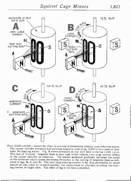
Squirrel Cage Motors 1,821
ARMATURE AT REST 100% SLIP
A VERY LARGE
CURRENT
VERY HIGH CUTTING RATE-
50 % SLIP'
MODERATE CURRENT
MODERATE--'.'' CUTTING RATE
BN LARGE
CURRENT
D 0 0 SMALL
CURRENT
CA:
-- 7S% SLIP
10:/ SLIP
Figs. 2,635 to 2,638.-Induction effect in starting of elementary cylinder type induction motor. The copper cylinder armature and rotating magnetic field of fig. 2,626 is here used to illus- trate the starting action. Fig. A shows armature at rest with field revolving 1,000 r.p.M. The rate of "cutting" magnetic lines is very high which induces very large current eddies in the copper cylinder as indicated. The torque produced gradually increases the speed of the armature which causes decreasing frequency in the cutting of magnetic lines as indi- cated in figs. B, C, and D. The very large starting current in fig. A is permissible for small motors as they come up to speed quickly, but means must be provided to reduce the start- ing current in larger sizes. The effect of lag is not here considered.
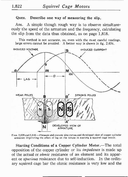
1,822 Squirrel Cage Motors
Ques. Describe one way of measuring the slip.
Ans. A simple though rough way is to observe simultane- ously the speed of the armature and the frequency, calculating the slip from the data thus obtained, as on page 1,818.
This method is not accurate, as, even with the most careful readings, large errors cannot be avoided. A better way is shown in fig. 2,634.
INDUCED VOLTAGE
- LAG - WEAK POLES 8
e
A'
DEVELOPED VIEW OF ARMATURE
INDUCED CURRENT
STRONG POLES
Fins. 2,639and 2,610.-Pressure and current sine curves and developed view of copper cylinder armature illustrating the etTect of lag on the torque in starting a squirrel cage motor.
Starting Conditions of a Copper Cylinder Motor.-The total opposition of the copper cylinder or its impedance is made up of the actual or ohmic resistance of an element and its appar- ent or spurious resistance due to self-induction. In the ordin- ary squirrel cage bar the ohmic resistance is very low and the
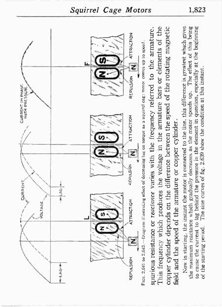
RE
PUL
SIO
N
CU
RR
EN
T
VO
LTA
GE
AT
TR
AC
TIO
N
RE
PU
LSIO
N
CU
RR
EN
T I
N P
HA
SE
W
ITH
P
RE
SS
UR
E
AT
TR
AC
TIO
N
RE
PU
LSIO
N
AT
TR
AC
TIO
N
FIG
S.
2,64
1 to
2,6
13.-
Dia
gram
illu
stra
ting
effe
ct o
f de
crea
sing
lag
on
torq
ue a
s a
squi
rrel
cag
: m
otor
co
mes
up
to s
peed
.
spur
ious
res
ista
nce
or r
eact
ance
va
ries
with
the
fr
eque
ncy
refe
rred
to
th
e ar
mat
ure.
T
his
freq
uenc
y w
hich
pr
oduc
es t
he v
olta
ge i
n th
e ar
mat
ure
bars
or
elem
ents
of
the
copp
er c
ylin
der
depe
nds
on t
he d
iffe
renc
e be
twee
n th
e sp
eed
of t
he r
otat
ing
mag
netic
fi
eld
and
the
spee
d of
the
arm
atur
e or
cop
per
cylin
der.
N
ow i
n st
artin
g, t
he i
nsta
nt t
he m
otor
is
conn
ecte
d to
the
lin
e, t
his
diff
eren
ce i
s gr
eate
st w
hich
giv
es
the
max
imum
rea
ctan
ce w
hich
gra
dual
ly d
ecre
ases
as
the
mot
or s
peed
s up
. T
he e
ffec
t of
th
is b
eing
to
cau
se th
e cu
rren
t to
lag
beh
ind
the
pres
sure
in
the
elem
ent
in q
uest
ion,
esp
ecia
lly a
t th
e be
ginn
ing
of t
he s
tart
ing
peri
od.
The
sin
e cu
rves
of
fig.
2,
639
show
the
con
ditio
n at
thi
s in
stan
t.
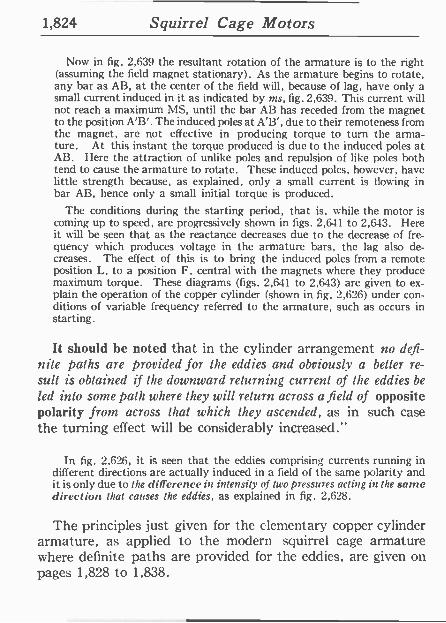
1,824 Squirrel Cage Motors
Now in fig. 2,639 the resultant rotation of the armature is to the right (assuming the field magnet stationary). As the armature begins to rotate, any bar as AB, at the center of the field will, because of lag, have only a small current induced in it as indicated by ins, fig. 2,639. This current will not reach a maximum MS, until the bar AB has receded from the magnet to the position A'B'. The induced poles at A'B', due to their remoteness from the magnet, are not effective in producing torque to turn the arma- ture. At this instant the torque produced is due to the induced poles at AB. I Iere the attraction of unlike poles and repulsion of like poles both tend to cause the armature to rotate. These induced poles, however, have little strength because, as explained, only a small current is flowing in bar AB, hence only a small initial torque is produced.
The conditions during the starting period, that is, while the motor is coming up to speed, are progressively shown in figs. 2,641 to 2,643. here it will he seen that as the reactance decreases due to the decrease of fre- quency which produces voltage in the armature bars, the lag also de- creases. The effect of this is to bring the induced poles from a remote position L, to a position F, central with the magnets where they produce maximum torque. These diagrams (figs. 2,641 to 2,643) are given to ex- plain the operation of the copper cylinder (shown in fig. 2,626) under con- ditions of variable frequency referred to the armature, such as occurs in starting.
It should be noted that in the cylinder arrangement no defi- nite paths are provided for the eddies and obviously a better re- sult is obtained if the downward returning current of the eddies be
led into some path where they will return across a field of opposite polarity from across that which they ascended, as in such case the turning effect will be considerably increased."
In fig. 2,626, it is seen that the eddies comprising currents running in different directions are actually induced in a field of the same polarity and it is only due to the di 'Terence in intensity of Iwo pressures acting in the same direction 11ral causes the eddies, as explained in fig. 2,628.
The principles just given for the elementary copper cylinder armature, as applied to the modern squirrel cage armature where definite paths are provided for the eddies, are given on pages 1,828 to 1,838.
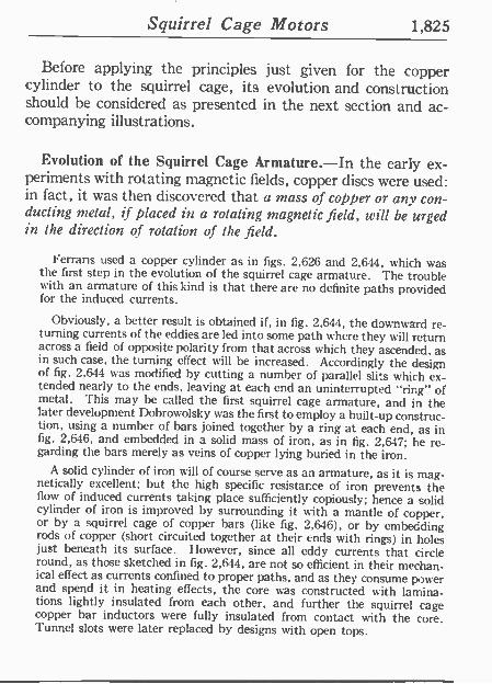
Squirrel Cage Motors 1,825
Before applying the principles just given for the copper cylinder to the squirrel cage, its evolution and construction should be considered as presented in the next section and ac- companying illustrations.
Evolution of the Squirrel Cage Armature.-In the early ex- periments with rotating magnetic fields, copper discs were used: in fact, it was then discovered that a mass of copper or any con- ducting metal, if placed in a rotating magnetic field, will be urged in the direction of rotation of the field.
Ferrans used a copper cylinder as in figs. 2,626 and 2,644, which was the first step in the evolution of the squirrel cage armature. The trouble with an armature of this kind is that there are no definite paths provided for the induced currents.
Obviously, a better result is obtained if, in fig. 2,644, the downward re- turning currents of the eddies are led into some path where they will return across a field of opposite polarity from that across which they ascended, as in such case, the turning effect will be increased. Accordingly the design of fig. 2.644 was modified by cutting a number of parallel slits which ex- tended nearly to the ends, leaving at each end an uninterrupted "ring" of metal. This may be called the first squirrel cage armature, and in the later development Dobrowolsky was the first to employ a built-up construc- tion, using a number of bars joined together by a ring at each end, as in fig. 2,646, and embedded in a solid mass of iron, as in fig. 2,647; he re- garding the bars merely as veins of copper lying buried in the iron.
A solid cylinder of iron u ill of course serve as an armature, as it is mag- netically excellent; but the high specific resistance of iron prevents the flow of induced currents taking place sufficiently copiously; hence a solid cylinder of iron is improved by surrounding it with a mantle of copper, or by a squirrel cage of copper bars (like fig. 2,646), or by embedding rods of copper (short circuited together at their ends with rings) in holes just beneath its surface. However, since all eddy currents that circle round, as those sketched in fig. 2,644, are not so efficient in their mechan- ical effect as currents confined to proper paths, and as they consume power and spend it in heating effects, the core was constructed with lamina- tions lightly insulated from each other, and further the squirrel cage copper bar inductors were fully insulated from contact with the core. Tunnel slots were later replaced by designs with open tops.
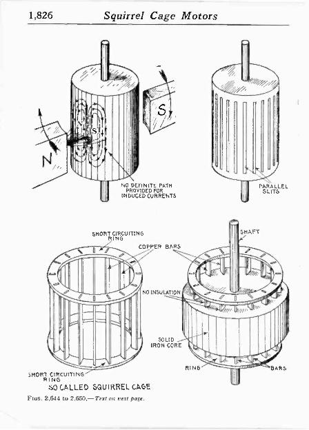
1,826 Squirrel Cage Motors
NO DEFINITE PATH PROVIDED FOR
INDUCED CURRENTS
SHORT CIRCUITING RING
COPPER BARS
NO INSULATION
SOLID IRON CORE
SHORT CIRCUITING RING
SO CALLED SQUIRREL CAGE
Fios. 2,644 to 2,650,-Text on next page.
PARALLEL SLITS
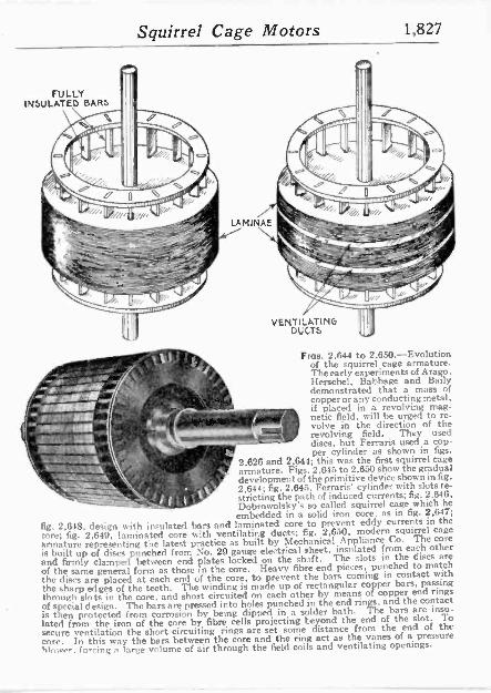
Squirrel Cage Motors 1,827
FULLY INSULATED BARS
VENTILATING DUCTS
From. 2,644 to 2,650.-Evolution of the squirrel cage armature. The early experiments of Arago, Herschel, Babbage and Bally demonstrated that a mass of copperor any conducting metal. if placed in a revolving mag- netic field, will be urged to re- volve in the direction of the
h w+. revolving field. They used discs, but Ferraris used a cop- per cylinder as shown in figs.
all 2,626 and 2,644; this was the first squirrel cage
n armature. Figs. 2,615 to 2.650 show the gradual development 4.of the primitive ylinder shown in fig.
fig. 2,645. Ferraris' cylinder with slots re -
II 1, _t.1 stricting the path of induced currents; fig. 2.646. Dobrowolsky's so called squirrel cage which he
embedded in a solid iron core, as in fig. 2,647;
fig. 2,61S, design with insulated bars and laminated core to prevent eddy currents in the core; fig. 2,649, laminated core with ventilating ducts; fig. 2,630, modern squirrel cace
armature representing the latest practice as built by Mechanical Appliance Co. The core
is built up of discs punched from No. 29 gauge electrical sheet. insulated from each other and firmly clamped between end plates locked on the shaft. The slots in the discs are
of the same general form as those in the core. Heavy fibre end pieces, punched to match the discs are placed at each end of the core, to prevent the bars coming in contact with the sharp edges of the teeth. The winding is made up of rectangular copper bars, passing
through slots in the core, and short circuited on each other by means of copper end rings
of special design. The bars are pressed into holes punched ín the end rings. and the contact is then protected from corrosion by being dipped in a solder bath. The bars are insu-
lated from the iron of the core by fibre cells projecting beyond the end of the slot. To
secure ventilation the short circuiting rings are set some distance from the end of the
core. In this way the bars between the core and the ring act as the vanes of a pressure
blower. forcing e large volume of air through the field coils and ventilating openings.
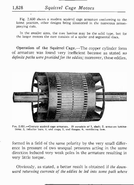
1,828 Squirrel Cage Motors
Fig. 2,650 shows a modern squirrel cage armature conforming to the latest practice, other designs being illustrated in the numerous accom- panying cuts.
In the smaller sizes, the core lamina' may be the solid type, but for the larger motors the core consists of a spider and segmental discs.
Operation of the Squirrel Cage.-The copper cylinder form of armature was found very inefficient because as stated no definite paths were provided for the eddies; moreover, these eddies,
- . -- / =-
r 42
-"_=2
2.651.-Century squirrel cage armature. It consists of 1, shaft; 2, armature lamina- tions; 3, inductor bars; 4, end rings; 5, end flanges; 6, ventilating fans.
formed in a field of the same polarity by the very small differ- ence in pressure of two unequal pressures acting in the same direction Induced very weak poles in the armature resulting in very little torque.
Obviously, as stated, a better result is obtained if the down- ward returning currents of the eddies be led into some path where
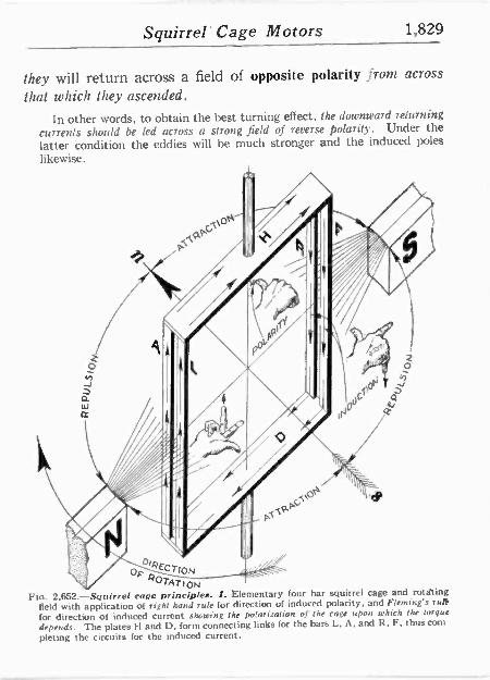
Squirrel' Cage Motors 1,829
they will return across a field of opposite polarity from across
that which they ascended.
In other words, to obtain the best turning effect, the downward returning
currents should be led across a strong field of reverse polarity. Under the latter condition the eddies will be much stronger and the induced poles
likewise.
OTATION
Fta. 2.652.-Squirrel cage principles. I. Elementary four bar squirrel cage and rotating field with application of right hand rule for direction of induced polarity, and Fleming's rut*
for direction of induced current showing the polarization of the cage upon which the torque
depends. The plates H and D, form connecting links for the bars L. A. and R. F, thus corn
pleting the circuits for the induced current.
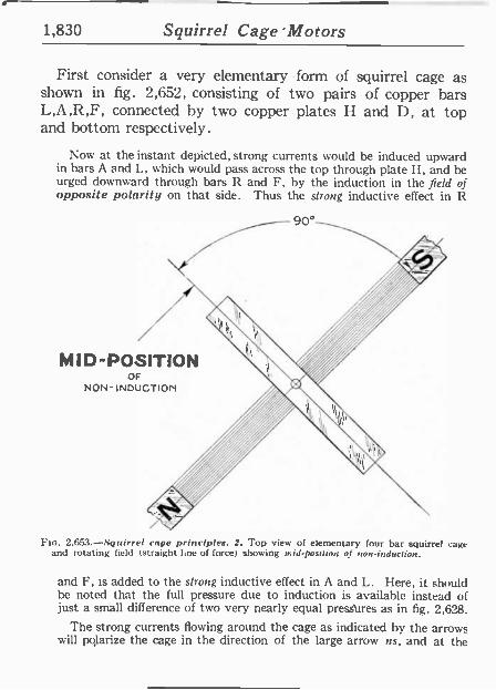
1,830 Squirrel Cage 'Motors
First consider a very elementary form of squirrel cage as shown in fig. 2,652, consisting of two pairs of copper bars L,A,R,F, connected by two copper plates H and D, at top and bottom respectively.
Now at the instant depicted, strong currents would be induced upward in bars A and L, which would pass across the top through plate I I, and he urged downward through bars R and F, by the induction in the field of opposite polarity on that side. Thus the strong inductive effect in R
MID -POSITION OF
NON - INDUCTION
Fit). 2.653.-Squirrel cage principles. 2. Top view of elementary four bar squirrel cage and rotating field (straight line of force) showing arid-pos:Iion of non -induction.
and F, is added to the strong inductive effect in A and L. Isere, it should be noted that the full pressure due to induction is available instead of just a small difference of two very nearly equal pressures as in fig. 2,628.
The strong currents flowing around the cage as indicated by the arrows will pqlarize the cage in the direction of the large arrow us, and at the
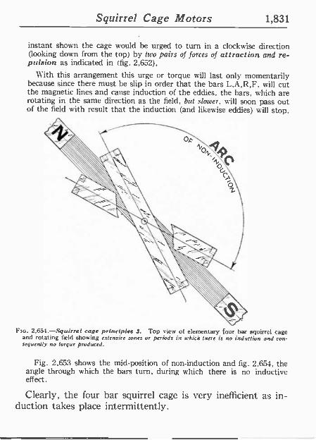
Squirrel Cage Motors 1,831
instant shown the cage would he urged to turn in a clockwise direction (looking down from the top) by two pairs of forces of attraction and re- pulsion as indicated in (fig. 2,652),
With this arrangement this urge or torque will last only momentarily because since there must he slip in order that the bars L,A,R,F, will cut the magnetic lines and cause induction of the eddies, the bars, which are rotating in the same direction as the field, but slower, will soon pass out of the field with result that the induction (and likewise eddies) will stop.
FIG. 2,653.-Squirrel cage principles 3. Top view of elementary four bar squirrel cage and rotating field showing extensive zones or periods in which Inert is no induction and con- sequently no torque produced.
Fig. 2,653 shows the mid -position of non -induction and fig. 2,651, the angle through which the bars turn, during which there is no inductive effect.
Clearly, the four bar squirrel cage is very inefficient as in- duction takes place intermittently.
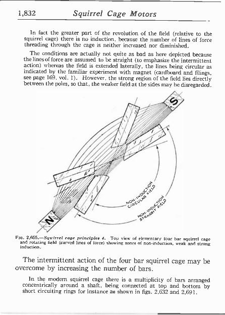
1,832 Squirrel Cage Motors
In fact the greater part of the revolution of the field (relative to the squirrel cage) there is no induction, because the number of lines of force threading through the cage is neither increased nor diminished.
The conditions are actually not quite as bad as here depicted because the lines of force are assumed to be straight (to emphasize the intermittent action) whereas the field is extended laterally, the lines being circular as indicated by the familiar experiment with magnet (cardboard and filings, see page 169, vol. 1). However, the strong region of the field lies directly between the poles, so that, the weaker field at the sides may be disregarded.
Flu. 2,655.-Squirrel cage principles 4. Top view of elementary four bar squirrel cage and rotating field (curved lines of force) showing zones of non -induction, weak and strong induction.
The intermittent action of the four bar squirrel cage may be overcome by increasing the number of bars.
In the modern squirrel cage there is a multiplicity of bars arranged concentrically around a shaft, being connected at top and bottom by short circuiting rings for instance as shown in figs. 2,632 and 2,691.
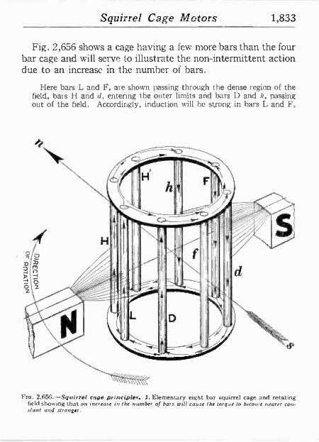
Squirrel Cage Motors 1,833
Fig. 2,656 shows a cage having a few more bars than the four bar cage and will serve to illustrate the non -intermittent action due to an increase in the number of bars.
Here bars L and F, are shown passing through the dense region of the field, bars I I and d, entering the outer limits and bars D and h, passing out of the field. Accordingly, induction will he strong in bars L and F,
Fro. 2,656. Squirrel cage principles. J. Elementary eight bar squirrel cage and rotating field showing that an increase in the number of bars will cause the torque to become nearer con- stant and stronger.
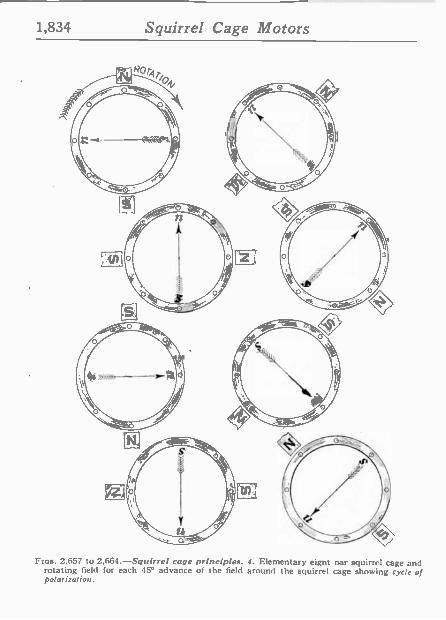
1,834 Squirrel Cage Motors
Ftas. 2.657 to 2,664.-Squirrel cage principles. J. Elementary eignt nar squirrel cage and rotating field for each 450 advance of the field around the squirrel cage showing cycle of polarization.
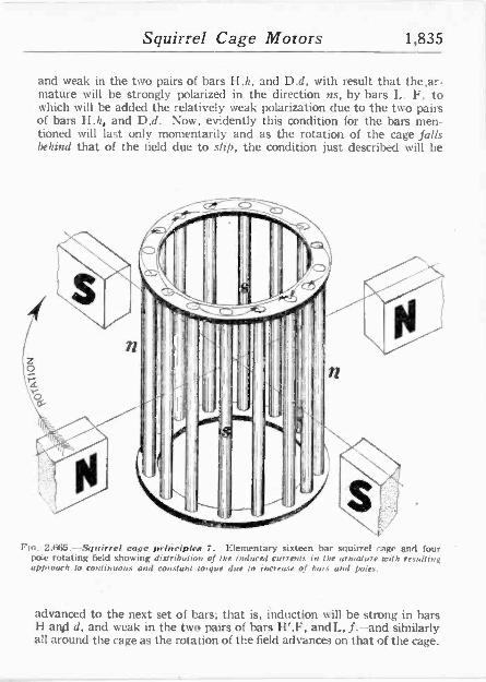
Squirrel Cage Motors 1,835
and weak in the two pairs of bars II,h, and D.d, with result that the,ar- mature will he strongly polarized in the direction ns, by bars L F, to which will be added the relatively weak polarization due to the two pairs of bars H.h, and D,d. Now, evidently this condition for the bars men- tioned will last only momentarily and as the rotation of the cage falls behind that of the field due to slip, the condition just described will be
Pm. 2,665.-Squirrel cage principles 7. Elementary sixteen bar squirrel cage and four '
pole rotating field showing distribution of the induced currents in the armature with resulting approach to continuous and constant torque due to increase of bars and poles.
advanced to the next set of bars; that is, induct'on will be strong in bars H and d, and weak in the two pairs of bars Il',F, and L, f.-and similarly all around the cage as the rotation of the field advances on that of the cage.
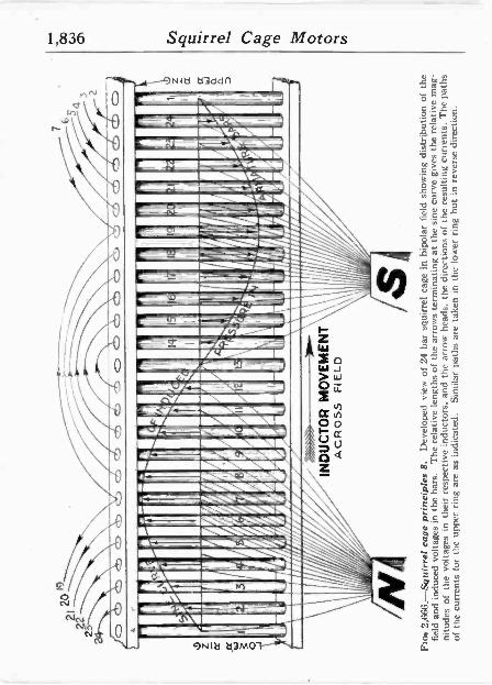
1,836 Squirrel Cage Motors
Nla a3ddn
mia.~ F==_ r
NIa a3M01---`,..-
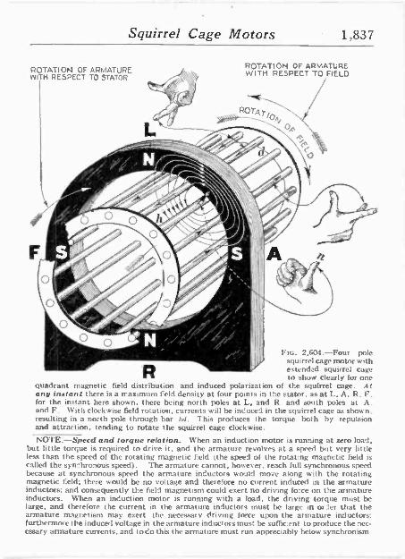
Squirrel Cage Motors 1,837
ROTATION OF ARMATURE WITH RESPECT TO STATOR
ROTATION OF ARMATURE WITH RESPECT TO FIELD
ii ¡. vv. Fie. 2,504.-Four pole squirrel cage motor with extended squirrel cage to show clearly for one
quadrant magnetic field distribution and induced polarization of the squirrel cage. At any instant there is a maximum Feld density at four points in the stator. as at L. A. R, F. for the instant here shown, there being north poles at L, and R. and south poles at A. and F. With clockwise field rotation, currents will he induced in the squirrel cage as shown. resulting in a north role through bar lid. This produces the torque both by repulsion and attraction, tending to rotate the squirrel cage clockwise.
NOTE -Speed and torque relation. When an induction motor is running at zero load, but little torque is required to drive it, and the armature revolves at a speed but very little less than the speed of the rotating magnetic field (the speed of the rotating magnetic field is called the synchronous speed). The armature cannot, however, reach full synchronous speed because at synchronous speed the armature inductors would move along with the rotating magnetic field; there would be no voltage and therefore no current induced in the armature inductors; and consequently the field magnetism could exert no driving force on the armature inductors. When an induction motor is running with a toad, the driving torque must be large, and therefore the current in the armature inductors must he large in order that the armature magnetism may exert the necessary driving force upon the armature inductors: furthermore the induced voltage in the armature inductors must be sufhc.enl to produce the nec- essary armature currents, and todo this the armature must run appreciably below synchronism
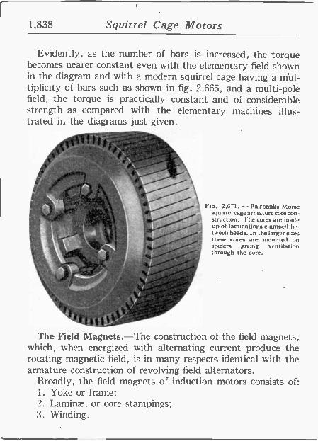
1,838 Squirrel Cage Motors
Evidently, as the number of bars is increased, the torque becomes nearer constant even with the elementary field shown in the diagram and with a modern squirrel cage having a mul- tiplicity of bars such as shown in fig. 2,665, and a multi -pole field, the torque is practically constant and of considerable strength as compared with the elementary machines illus- trated in the diagrams just given.
.1316 - `.
"4. dr o Y .\\
...
s
. ,i .-'` á- ^' .. , - ./'
t,), p
3:1 - .
The Field Magnets.-The construction of the field magnets, which, when energized with alternating current produce the rotating magnetic field, is in many respects identical with the armature construction of revolving field alternators.
Broadly, the field magnets of induction motors consists of: 1. Yoke or frame; 2. Laminae, or core stampings; 3. Winding.
Flo. 2,471. - Fairbanks -Worse squirrel cage arms ture core con- struction. The cores are made up of laminations clamped be- tween heads. In the larger sizes these cores are mounted on spiders giving ventilation through the core.
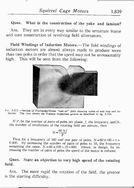
Squirrel Cage Motors 1,839
Ques. What is the construction of the yoke and laminae?
Ans. They are in every way similar to the armature frame and core construction of revolving field alternators.
Field Windings of Induction Motors.-The field windings of induction motors are almost always made to produce more than two poles in order that the speed may not be unreasonably high. This will be seen from the following:
i Fa;. 2,672.-Section of Fairbanks -N orse "cast -on" joint showing union of end ring and in-
ductor. The view shows the V-shape inspection groove as described in fig. 2,700.
If P, he the number of pairs of poles per phase, f, the frequency, and N, the number of revolutions of the rotating field per minute, then
N=60Xf p
Thus for a frequency of 100 and one pair of poles, N =60 X10041 = 6,000. By increasing the number of pairs of poles to 10, the frequency remaining the same, N=60X100=10=600. Hence, in design, by in- creasing the number of pairs of poles the speed of the motor is reduced.
Ques. State an objection to very high speed of the rotating field.
Ans. The more rapid the rotation of the field, the g eater is the starting difficulty.'
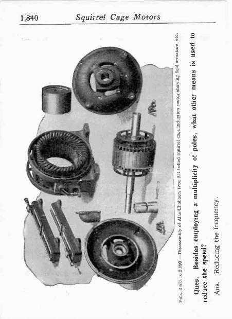
.--,
..,no
lo --
.'
...:,i
,
'_ y ' víti
Í r
' ,
,
,- "
,...,.
.--,
1---
^":.-
-.
l,,` k'
-
.
. , r,
-
` ' d
:,
..((
. `
,
t' .
.1
g.
- .
- ,
t o
,i,,-
e.
r to
, ' S
-,-'-
-':--
'.7,5
:7->
l«>
: 41
41.
r r'
1
i¡á,
;. -
ep
R
$ t
}asi
-
Fin
n. 2
,673
to
2.69
0.-D
isas
sem
bly
of A
llis-
Cha
lmer
s ty
pe A
R b
elte
d sq
uirr
el c
age
indu
ctio
n m
otor
sho
win
g fie
ld a
rmat
ure,
etc
.
Que
s.
Bes
ides
em
ploy
ing
a m
ultip
licity
of
pole
s,
wha
t ot
her
mea
ns
is
used
to
redu
ce t
he
spee
d?
Ans
. R
educ
ing
-the
fre
quen
cy.
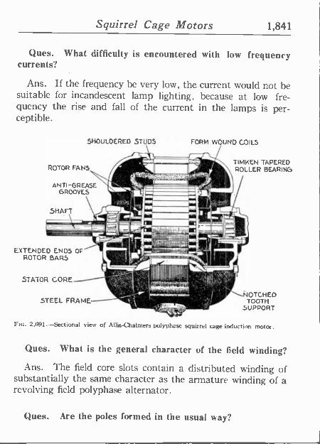
Squirrel Cage Motors 1,841
Ques.- What difficulty is encountered with low frequency currents? _
Ans. If the frequency be very low, the current would not be suitable for incandescent lamp lighting, because at low fre- quency the rise and fall of the current in the lamps is per- ceptible.
SHOULDERED STUDS FORM WOUND COILS
TIMKEN TAPERED ROTOR FANS ROLLER BEARING
ANTI -GREASE GROOVES
SHAFT
EXTENDED ENDS OF ROTOR BARS
STATOR CORE
STEEL FRAME o lzu.
Ftc. 2,691.-Sectional view of Allis-Qalmers polyphase squirrel cage induction motor.
Ques. What is the general character of the field winding?
Ans. The field core slots contain a distributed winding of substantially the same character as the armature winding of a revolving field polyphase alternator.
I,"\ÑOTCHED TOOTH
SUPPORT
Ques. Are the poles formed in the usual way?
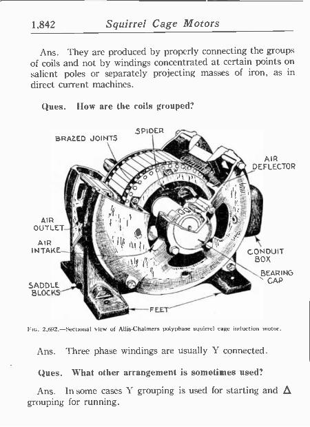
1,842 Squirrel Cage Motors
Ans. They are produced by properly connecting the groups of coils and not by windings concentrated at certain points on salient poles or separately projecting masses of iron, as in direct current machines.
Ques. How are the coils grouped?
SPIDER BRAZED JOINTS
AIR OUTLET
AIR INTAKE --
SADDLE BLOCKS -
AIR DEFLECTOR
CONDUIT BOX
BEARING CAP
2,692.-Sectional view of Allis-Chalmers polyphase squirrel cage induction motor.
Ans. Three phase windings are usually Y connected.
Ques. What other arrangement is sometimes used?
Ans. In some cases Y grouping is used for starting and á grouping for running.
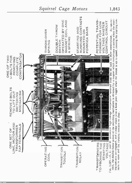
ON
E S
ET
OF
LI
NE
, M
OT
OR
AN
D
TR
AN
SF
OR
ME
R
TA
P T
ER
MIN
ALS
OP
ER
AT
ING
C
OIL
TR
AN
SIT
ION
T
OG
GLE
TR
AN
SIT
ION
R
ELA
Y
TR
AN
SF
OO
RM
ER
S
TO
PR
OV
IDE
TH
E
ST
AR
TIN
G
VO
LTA
GE
TH
RO
W -O
VE
R
SP
RIN
G
DO
UB
LE T
HR
OW
S
WIT
CH
O
PE
RA
TE
D B
Y O
NE
M
AG
NE
T C
OIL
AN
D
A S
PR
ING
RE
MO
VE
3 B
OLT
S
TO
LIF
T O
UT
S
WIT
CH
ING
M
EC
HA
N IS
M
ON
E O
F T
WO
U
-B
OLT
S F
OR
R
EM
OV
ING
C
OM
PLE
TE
C
OM
PE
NS
AT
OR
-4N
,ytO
L
ELf
r A
,i_ %
iii
M S
TA
RT
ING
AN
D
RU
NN
ING
CO
NT
AC
TS
M
OU
NT
ED
ON
fi
, F
OR
MIC
A B
AR
S
,°
I d
PO
TE
NT
IAL
TR
AN
S-
FO
RM
ER
FO
R L
OW
V
OLT
AG
E M
AS
TE
R
I cs
C
ON
TR
OL
CIR
CU
IT
PIG
. 2.
693.
-E.
C.
and
M
antn
mat
ir h
igh
...Ita
ga r
nmpw
niat
or r
vmW
wi
from
tho
oi
l to
nic
to o
how
co
nstr
uctio
n.
In o
pera
- tio
n, t
he d
oubl
e th
row
act
ion
of t
he s
witc
hing
mec
hani
sm i
s ob
tain
ed b
y a
mag
net
whi
ch c
ompr
esse
s a
sprin
g w
hen
the
star
t-
ing
cont
acts
ar
e en
gage
d, a
nd
a re
lay
whi
ch t
rips
a kn
ee j
oint
tog
gle
whe
n th
e m
otor
is
up t
o sp
eed,
cau
sing
the
sta
rtin
g co
n-
tact
s to
ope
n an
d th
e ru
nnin
g co
ntac
ts t
o cl
ose.
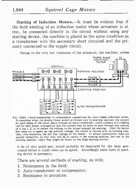
1,844 Squirrel Cage Motors
Starting of Induction Motors.-It must be evident that if
the field winding of an induction motor whose armature is at rest, be connected directly in the circuit without using any starting device, the machine is placed in the same condition as a transformer with the secondary short circuited and the pri- mary connected to the supply circuit.
Owing to the very low resistance of the armature, the machine, unless
THREE PHASE (E.) INt.
N' OTOR
5wíTGH
PHASE A ag=03 0=01) E3=11 PHASE B PHASE C
.... ~ iI'I ni ¡fi n 1'i'Í RUNNING POSirION
PHASE C
PHASE B
PHASE A
STARTING POSITION
AUTO -TRANSFORMER
FIG. 2,694.-Auto-transformer or compensator connections for three phase induction motor. In operation when the double throw switch is t frown over to starting position, the current for each phase of the motor flows through an auto -transformer, which consists of a choking coil for each Phase, arranged so that the current may be made to pass through any portion of it (as 1, 2, 3) to reduce the voltage to the p oper amount for starting. After the motor has come up to speed on the reduced voltage. the switch is thrown over to running posi- tion, thus supplying the full line voltage to the motor. In actual construction fuses are usually connected, so that they will be in circuit in the running position, but not in the starting position, where they might be blown by the large starting current.
it he of very small size, would probably be destroyed by the heat gen- erated before it could come up to speed. Accordingly some form of start- ing device is necessary.
There are'several methods of starting, as with:
1. Resistances in the field; 2. Auto -transformer or compensator; 3. Resistance in armature.
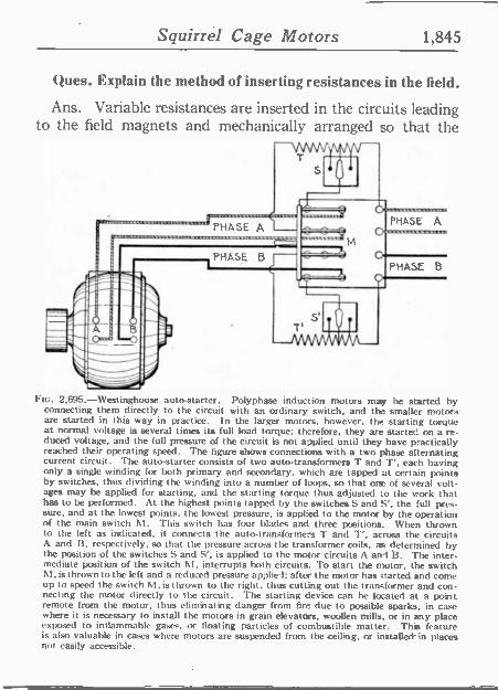
Squirrel Cage Motors 1,845
Ques. Explain the method of inserting resistances in the field.
Ans. Variable resistances are inserted in the circuits leading to the field magnets and mechanically arranged so that..the
FIG. 2,695.-Westinghouse auto -starter. Polyphase induction motors may be started by connecting them directly to the circuit with an ordinary switch, and the smaller motors are started in this way in practice. In the larger motors, however. the starting torque at normal voltage is several times its full load torque: therefore, they are started on a re- duced voltage, and the full pressure of the circuit is not applied until they have practically reached their pperating speed. The figure shows connections with a two phase alternating current circuit. The auto -starter consists of -two auto -transformers T and T'. each having only a single winding for both primary and secondary, which are tapped at certain points by switches, thus dividing the winding into a number of loops, so that one of several volt- ages may be applied for starting, and the starting torque thus adjusted to the work that has to be performed. At the highest points tapped by the switches S and S', the full pres- sure, and at the lowest points. the lowest pressure. is applied to the motor by the operation of the main switch M. This switch has four blades and three positions. When thrown to the left as indicated, it connects the auto -transformers T and T', across the circuits A and 13. respectively, so that the pressure across the transformer coils, as determined by the position of the switches S and S', is applied to the motor circuits A and ». The inter- mediate position of the switch 1\1, interrupts both circuits. To start the motor, the switch M. is thrown to the left and a reduced pressure applied; after the motor has started and come up to speed the switch M. is thrown to the right, thus cutting out the transformer and con- necting the motor directly to the circuit. The starting device can be located at a point remote from the motor, thus eliminating danger from fire due to possible sparks, in case where it is necessary to install the motors in grain elevators, woollen mills, or in any place
exposed to inflammable gases. or floating particles of combustible matter. This. feature is also valuable in cases.where motors are suspended from the ceiling. or installed -in places not easily accessible.
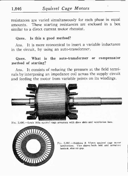
1,846 Squirrel Cage Motors
resistances are varied simultaneously for each phase in equal amounts. These starting resistances are enclosed in a box
similar to a direct current motor rheostat.
(hues. Is this a good method?
Ans. It is more economical to insert a variable inductance in the circuit, by using an auto -transformer.
Ques. What is the auto -transformer or compensator method of starting?
Ans. It consists of reducing the pressure at the field termi- nals by interposing an impedance coil across the supply circuit and feeding the motor from variable points on its windings.
Fin. 2.696.-Louis Allis squirrel cage armature with skew slots and ventilation fans.
FIG. 2,697.-Robbins & Myers squirrel cage motor laminations. View shows both field and armature lamina, also air gap.
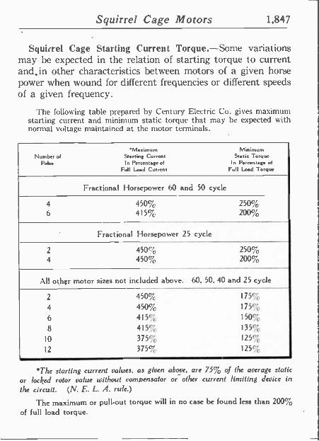
Squirrel Cage Motors 1,847
Squirrel Cage Starting Current Torque.-Some variations may be expected in the relation of starting torque to current and, in other characteristics between motors of a given horse power when wound for different frequencies or different speeds of a given frequency.
The following table prepared by Century Electric Co. gives maximum starting current and minimum static torque that may he expected with normal voltage maintained at the motor terminals.
Maz mum Min' Nmberof Starting Current StegigtTorque
Pole. In Percentage of In Percentage of Full Load Current Full Load Torque
Fractional Horsepower 60 and 50 cycle
4 450% 250% 6 415% 200%
Fractional Horsepower 25 cycle
2 450% 250% 4 450% 200%
All other motor sizes not included above. 60, 50. 40 and 25 cycle
2 450% 175%
4 450% 175%
6 415% 150%
8 415% 135%
10 375% 125%
12 375% 125%
*The starting current values, as given above, are 75% of the average static
or locked rotor value without cornoensºtor or- other current limiting device in
the circuit. (N. E. L. A. rule.)
The maximum or pull-out torque will in no case be found less than 200%
of full load torque.
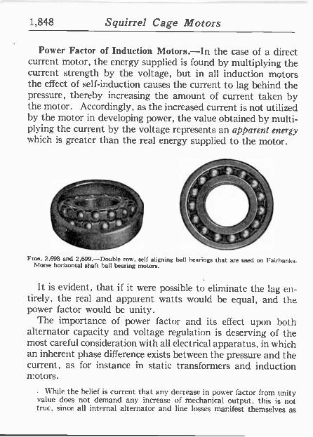
1,848 Squirrel Cage Motors
Power Factor of Induction Motors.-In the case of a direct current motor, the energy supplied is found by multiplying the current strength by the voltage, but in all induction motors the effect of self-induction causes the current to lag behind the pressure, thereby increasing the amount of current taken by the motor. Accordingly, as the increased current is not utilized by the motor in developing power, the value obtained by multi- plying the current by the voltage represents an apparent energy which is greater than the real energy supplied to the motor.
^
,
L )71.
, ,11\1
., ` ; _- Fins. 2.698 and 2,699.-Double row, self aligning ball bearings that are used on Fairbanks.
Morse horizontal shaft ball bearing motors.
It is evident, that if it were possible to eliminate the lag en- tirely, the real and apparent watts would be equal, and the power factor would be unity.
The importance of power factor and its effect upon both alternator capacity and voltage regulation is deserving of the most careful consideration with all electrical apparatus, in which an inherent phase difference exists between the pressure and the current, as for instance in static transformers and induction motors.
. While the belief is current that any decrease in power factor from unity value does not demand any increase of mechanical output, this is not true, since all internal alternator and line losses manifest themselves as
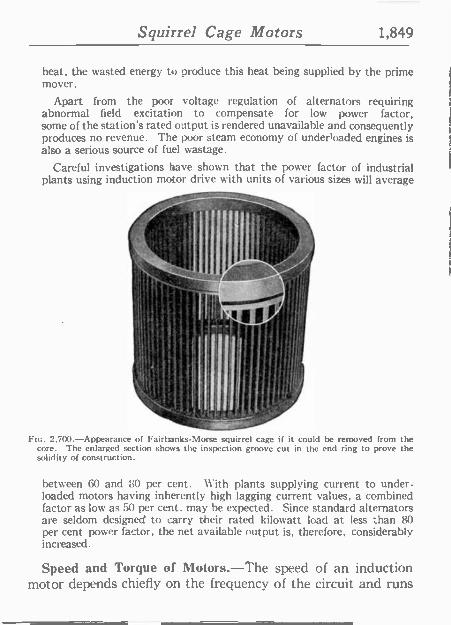
Squirrel Cage Motors 1,849
heat, the wasted energy to produce this heat being supplied by the prime mover.
Apart from the poor voltage regulation of alternators requiring abnormal field excitation to compensate for low power factor, some of the station's rated output is rendered unavailable and consequently produces no revenue. The poor steam economy of under!oaded engines is also a serious source of fuel wastage.
Careful investigations have shown that the power factor of industrial plants using induction motor drive with units of various sizes will average
.S:
lI
y,J Fio. 2.700.-Appearance of Fairtunks-Morse squirrel cage if it could he removed from the
core. The enlarged section shows the inspection groove cut in the end ring to prove the solidity of construction.
between 60 and 80 per cent. With plants supplying current to under - loaded motors having inherently high lagging current values, a combined factor as low as 50 per cent. may he expected. Since standard alternators are seldom designed to carry their rated kilowatt load at less than 80 per cent power factor, the net available output is, therefore, considerably increased.
Speed and Torque of Motors,-The speed of an induction motor depends chiefly on the frequency of the circuit and runs
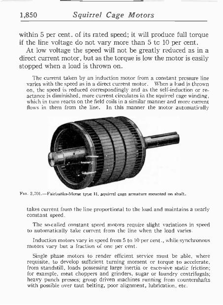
1,850 Squirrel Cage Motors
within 5 per cent. of its rated speed; it will produce full torque if the line voltage do not vary more than 5 to 10 per cent.
At low voltage the speed will not be greatly reduced as in a direct current motor, but as the torque is low the motor is easily stopped when a load is thrown on.
The current taken by an induction motor from a constant pressure line varies with the speed as in a direct current motor. When a load is thrown on, the speed is reduced correspondingly and as the self-induction or re- actance is diminished, more current circulates in the squirrel cage winding, which in turn reacts on the field coils in a similar manner and more current flows in them from the line. In this manner the motor automatically
2.701 -Fairbanks -Morse type H, squirrel cage armature mounted on shaft.
takes current from the line proportional to the load and maintains a nearly constant speed.
The so-called constant speed motors require slight variations in speed to automatically take current from the line when the load varies.
Induction motors vary in speed from 5 to 10 per cent., while synchronous motors vary but a fraction of one per cent.
Single phase motors to render efficient service must be able, where requisite, to develop sufficient turning moment or torque to accelerate, from standstill, loads possessing large inertia or excessive static friction; for example. meat choppers and grinders, sugar or laundry centrifugals; heavy punch presses; group driven machines running from countershafts with possible over taut belting, poor alignment, lubrication, etc.
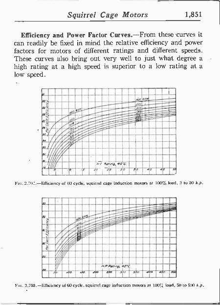
. e ' o . . ' . -
: . . ' . I ...
' ' . S . .
. i.. .....s.. .
Immg"::::22--
1i :Aj . . . _- --__ .59-511-Ti aa .%.r//iC : Ié0i%%áAi..
%%.r i" .... MUR .... . ,,..a.... . 9, ._. : a...,°9,
.,o .
. . .inr . ,° .MM...Er 11'. . . 1
s .._...mog_ -- --- i=.. .m_-----_- » - - lm. /w+piiw~% .I%pdamí%. I///.% . . uíi i...i.. ~// guisamos
I%/!% ... MIMES11111~ iEii .~ iíMiMiM7h .1 . 11 . . . 1
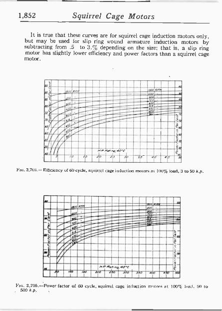
1,852 Squirrel Cage Motors
It is true that these curves are for squirrel cage induction motors only, but may he used for slip ring wound armature induction motors by subtracting from .5 to 3.% depending on the size; that is, a slip ring motor has slightly lower efficiency and power factors than a squirrel cage motor.
. 1 St '
r 900R/t't ' ̀ -,dr -at - I[A
úM
V C
h. & t
ID, _
NP Rpnnp, 00'C ' -Y `io e x iJ tO . Fla. 2,703.-Efficiency of 60 cycle, squirrel cage induction motors a 100% load, 3 to 50 h.p.
Flo. 2,705.-Power factor of 60 cycle, squirrel cage induction motors at 100% load. 50 to 500 h.p.
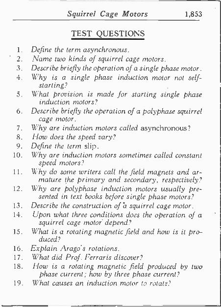
Squirrel Cage Motors 1,853
TEST QUESTIONS
1. Define the term asynchronous. 2. Name two kinds of squirrel cage motors. 3. Describe briefly the operation of a single phase motor. 4. Why is a single phase induction motor not self-
. starting? 5. What provision is made for starting single phase
induct ion motors? 6. Describe briefly the operation of a polyphase squirrel
cage motor. 7. Why are induction motors called asynchronous? 8. How does the speed vary? 9. Define the term slip.
10. Why are induction motors sometimes called constant speed motors?
11. \V'hy do some writers call the field magnets and ar- mature the primary and secondary, respectively?
12. Why are polyphase induction motors usually pre- sented in text books before single phase motors?
13. Describe the construction of h squirrel cage motor. 14. Upon what three conditions does the operation of a
squirrel cage motor depend? 15. What is a rotating magnetic field and how is it pro-
duced? 16. Explain Arago's rotations. 17. What did Prof. Ferraris discover? 18. How is a rotating magnetic field produced by two
phase current; how by three phase current? 19. What causes an induction motor to rotate?
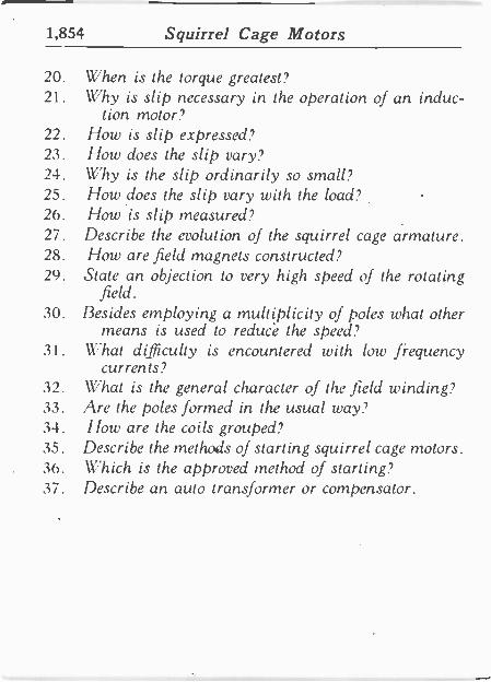
1,854 Squirrel Cage Motors
20. When is the torque greatest? 91. Why is slip necessary in the operation of an induc-
tion motor? 22. How is slip expressed? 23. How does the slip vary? 24. Why is the slip ordinarily so small? 25. flow does the slip vary with the load? 26. //ow. is slip measured? 27. Describe the evolution of the squirrel cage armature. 28. l low are field magnets constructed? 29. State an objection to very high speed of the rotating
field. 30. 13esides employing a multiplicity of poles what other
means is used to reduce the speed 31. What difficulty is encountered with low frequency
currents? 32. What is the general character of the field winding? 33. Are the poles formed in the usual way? 34. How are the coils grouped? 35. Describe the methods of starting squirrel cage motors. 36. Which is the approved method of starting? 37. Describe an auto transformer or compensator.
Related Documents