Energy Procedia 48 (2014) 453 – 463 Available online at www.sciencedirect.com ScienceDirect 1876-6102 © 2014 The Authors. Published by Elsevier Ltd. Selection and peer review by the scientific conference committee of SHC 2013 under responsibility of PSE AG doi:10.1016/j.egypro.2014.02.054 SHC 2013, International Conference on Solar Heating and Cooling for Buildings and Industry September 23-25, 2013, Freiburg, Germany Electric power generation from solar pond using combination of thermosyphon and thermoelectric modules Sura Tundee a *, Narong Srihajong a , Suparerk Charmongkolpradit a a Department of Mechanical Engineering, Faculty of Engineering, Rajamangala University of Technology Isan Khon Kaen Campus,Khon Kaen 40000, Thailand Abstract Salinity-gradient solar pond is one type of solar collector with the ability to store thermal energy for long period of time and lower cost of construction compared with the other type of solar collector. It can collect and store solar heat at temperatures up to 80 o C. A system in which heat from the lower zone is transferred to the hot surface of the thermoelectric modules using gravity- assisted heat pipes as thermosyphons has been investigated experimentally.The temperature difference between the lower convective zone and the upper convective zone is applied across the hot and cold surfaces of the thermoelectric modules. In the salinity gradient solar pond, a insulated solar pond with a surface area of 7 m 2 and a depth of 1.3 m was built at Rajamangala University of Technology Isan Khon Kaen Campus,Thailand to conduct performance experiments. From the results of experiment by using water as working fluid, the temperature of the solar pond in lower convective zone is at 50 o C.It can be seen that the thermoelectric is able to generate electricity at 36.25 mV. Using R134a as a working fluid, the temperature of heat pond in lower convective zone is at 41 o C.Due to this, thermoelectric generates electricity at 234.25 mV. . Research results in the present work indicate that there is a significant potential for electric power generation from small solar ponds through a simple and passive device incorporating thermosyphons and thermoelectric cells. Keywords: Solar pond;Thermosyphon;Thermoelectric * Corresponding author. Tel.: +66-43-336371 Fax. +66-43-237483 E-mail address: [email protected] © 2014 The Authors. Published by Elsevier Ltd. Selection and peer review by the scientific conference committee of SHC 2013 under responsibility of PSE AG

Welcome message from author
This document is posted to help you gain knowledge. Please leave a comment to let me know what you think about it! Share it to your friends and learn new things together.
Transcript
Energy Procedia 48 ( 2014 ) 453 – 463
Available online at www.sciencedirect.com
ScienceDirect
1876-6102 © 2014 The Authors. Published by Elsevier Ltd. Selection and peer review by the scientifi c conference committee of SHC 2013 under responsibility of PSE AGdoi: 10.1016/j.egypro.2014.02.054
SHC 2013, International Conference on Solar Heating and Cooling for Buildings and Industry September 23-25, 2013, Freiburg, Germany
Electric power generation from solar pond using combination of thermosyphon and thermoelectric modules
Sura Tundeea*, Narong Srihajonga , Suparerk Charmongkolpradita a Department of Mechanical Engineering, Faculty of Engineering, Rajamangala University of Technology Isan Khon Kaen Campus,Khon
Kaen 40000, Thailand
Abstract
Salinity-gradient solar pond is one type of solar collector with the ability to store thermal energy for long period of time and lower cost of construction compared with the other type of solar collector. It can collect and store solar heat at temperatures up to 80oC. A system in which heat from the lower zone is transferred to the hot surface of the thermoelectric modules using gravity-assisted heat pipes as thermosyphons has been investigated experimentally.The temperature difference between the lower convective zone and the upper convective zone is applied across the hot and cold surfaces of the thermoelectric modules. In the salinity gradient solar pond, a insulated solar pond with a surface area of 7 m2 and a depth of 1.3 m was built at Rajamangala University of Technology Isan Khon Kaen Campus,Thailand to conduct performance experiments. From the results of experiment by using water as working fluid, the temperature of the solar pond in lower convective zone is at 50 oC.It can be seen that the thermoelectric is able to generate electricity at 36.25 mV. Using R134a as a working fluid, the temperature of heat pond in lower convective zone is at 41 oC.Due to this, thermoelectric generates electricity at 234.25 mV. . Research results in the present work indicate that there is a significant potential for electric power generation from small solar ponds through a simple and passive device incorporating thermosyphons and thermoelectric cells. © 2014 The Authors. Published by Elsevier Ltd. Selection and peer review by the scientific conference committee of SHC 2013 under responsibility of PSE AG.
Keywords: Solar pond;Thermosyphon;Thermoelectric
* Corresponding author. Tel.: +66-43-336371 Fax. +66-43-237483
E-mail address: [email protected]
© 2014 The Authors. Published by Elsevier Ltd. Selection and peer review by the scientific conference committee of SHC 2013 under responsibility of PSE AG
454 Sura Tundee et al. / Energy Procedia 48 ( 2014 ) 453 – 463
1. Introduction
Energy is one of the factors necessary for everyone. We use energy in various forms over the year, which causes a number of significant power sources in the World to decline by the amount of time spent. As a result, many countries start to realize and have already began to look for alternative renewable energy to replace those that are vanishing. There are many types of renewable energy such as wind power, hydro power, and biomass. There is also another type of renewable energy that is always available, inexhaustible, and not adversely affecting the environment. It is solar energy. To use such energy; however, there must be a device that can store heat energy from the sun so that the stored energy can be utilized later for various usages.
Solar pond is another option that can be used to collect heat from the sun due to its lower cost per square meter than other types of solar energy equipment. This research has therefore used the solar pond as a storing source of thermal energy from the sun and uses the thermosyphon heat pipe to transfer heat energy to the thermoelectric cells where electricity is generated from the temperature difference between the hot and the cold sides.
1.1 Solar pond
Solar pond is a device to collect and store energy. It can operate continuously all year long. Solar ponds collect energy from solar radiation. The radiant heat is collected at the bottom side of the pond and this amount of heat would be used later.
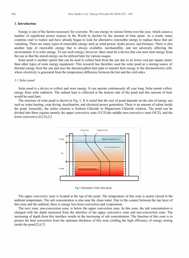
The structure of solar pond is shown in Fig. 1. It is noted that the size of pond depends on the aim of energy use such as water heating, crop drying, desalination, and electrical power generation. There is an amount of saline inside the pond. Generally, the saline solution is Sodium Chloride or Magnesium Chloride solution. The pond can be divided into three regions namely the upper convective zone (UCZ),the middle non-convective zone (NCZ), and the lower convective (LCZ).[1]
Fig.1.Schematic of the solar pond
The upper convective zone is located at the top of the pond. The temperature of this zone is nearly closed to the ambient temperature. The salt concentration is also near the clean water. Due to the contact between the top layer of this zone and the ambient, there is energy loss from convection and evaporation.
The next zone, non-convection zone, is below the upper convection zone. In this zone, the salt concentration is changed with the depth measured from the interface of the upper convective zone and non-convection zone. The increasing of depth from this interface results in the increasing of salt concentration. The function of this zone is to protect the heat convection from the optimum thickness of this zone yielding the high efficiency of energy storing inside the pond.[2,6,7]
Sura Tundee et al. / Energy Procedia 48 ( 2014 ) 453 – 463 455
The last zone, lower convection zone, is the most salt-concentrated zone. The concentration in this zone is uniform. When the pond receives heat from solar radiation, the heat penetrates through the upper and non-convection zone to be stored at the bottom side.
1.2. Thermosyphon
The gravity assisted thermosyphon is an effective heat transfer device that utilizes latent heat of the working fluid, flowing under the influence of gravity, to transport heat from the source to the sink.[3] As the latent heat of vaporization is relatively high, the thermosyphons can transfer large quantity of heat with very small end to end temperature differential and thus low thermal resistance. In the thermal analysis of the gravity assisted thermosyphon corrections from ESDU [4] were used. The total thermal resistance – Zt [K/W] from heat source to the heat sink for thermosyphon is related to the actual overall heat transfer - oaQ [W] as below:
t
effoa Z
TQ (1)
Where, effT [K] is effective temperature difference between heat source and heat sink and defined by:
hsisoeff TTTT (2)
In Equation (2), Tso [K] is heat source temperature; siT [K] is heat sink temperature
and hT [K] is mean temperature difference due to hydrostatic head which is given as:
2FTT
T vph (3)
Where, F is the filling ratio and defined by:
ets
l
LAV
F (4)
Vl [m3] is volume of working fluid, Ats[m2] is internal cross section area of thermosyphon pipe and Le [m] is evaporator length. Tp [K] the saturation temperature at the bottom of the pool is given by
dHdT
FLTT sevp (5)
In Equation (5), Tv [K] is the temperature of the vapour in the adiabatic and condenser section Ts [K] is the saturation temperature of the boiling liquid and H [m] is the hydrostatic height of the liquid in the evaporator.
1
v
lss
LgT
dHdT
(6)
Where, g [m/s2] is acceleration due to gravity Tv [K] is determined from
sisot
siv TTZ
ZZZTT 987 (7)
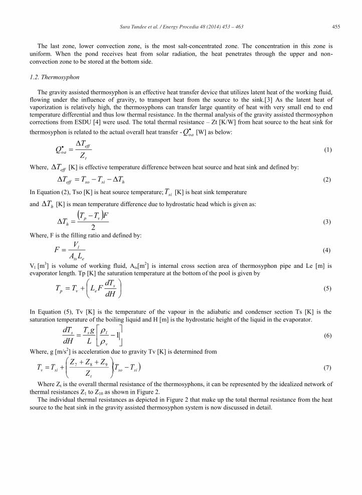
Where Zt is the overall thermal resistance of the thermosyphons, it can be represented by the idealized network of thermal resistances Z1 to Z10 as shown in Figure 2.
The individual thermal resistances as depicted in Figure 2 that make up the total thermal resistance from the heat source to the heat sink in the gravity assisted thermosyphon system is now discussed in detail.
456 Sura Tundee et al. / Energy Procedia 48 ( 2014 ) 453 – 463
Fig.2.Thermal resistance and their locations
Z1 and Z9 are thermal resistance between “heat source and the evaporator external surface” and “heat sink and condenser external surface” respectively. These can be expressed as:
eoeoshZ 1
1 (8)
coco shZ 1
9 (9)
heo, hco[W/m2.K] are evaporator and condenser outside heat transfer coefficient, and seo, sco [m2] are evaporator and condenser external surface area respectively.
Z2 and Z8 are the thermal resistances across the thickness of the thermosyphon tube wall in the “evaporative section” and “condenser section” respectively, which can be determined as
pe
io
kLDD
Z2
/ln2 (10)
pc
io
kLDD
Z2
/ln8 (11)
Where, Do, Di [m] are the internal and external diameter of thermosyphon tube, Le, Lc [m] are evaporator and condenser length and kp [W/m.K] is thermal conductivity of thermosyphon pipe material.
Z3 and Z7 are the internal resistances due to pool and film boiling of the working fluid which is explained as follows:
Z3p [K/W] is resistance offered by pool boiling inside the evaporator:
6.04.02.0
33
1LeDQg
Zi
p (12)
Where, 3 [K-1] is the figure of merit for the case of pool boiling
23.0
1.04.025.0
7.03.05.0
325.03a
v
lvlv
plll
pp
hCk (13)
Z3f [K/W] is resistance from film boiling at the evaporator section:
3/42
3/13/4
3/1
3 LegDCQ
Zi
of (14)

Sura Tundee et al. / Energy Procedia 48 ( 2014 ) 453 – 463 457
Where C is constant of cylinder tube
235.03
41 3
4
C (15)
Where, 2 [K-1] is the figure of merit for the case of film boiling case:
4/123
2l
llLk (16)
Where, hvl [W/kg] is latent heat of evaporation for working fluid, kl [W/m.K] is thermal conductivity of working fluid in liquid phase, l [kg/m3] is liquid density, v [kg/m3] is vapour density, l [Pa.s] is liquid dynamic
viscosity, lpC [J/kg.K] is liquid specific heat capacity at constant pressure, Pv [Pa] is vapour pressure and Pa [Pa] is
atmospheric pressure In this case, condition for using Z3p and Z3f to calculate the value of Z3 is as follow:
IfZ3p > Z3f then Z3 = Z3p (17)
If Z3p < Z3f then Z3 = (Z3p)F+(Z3f)(1-F) (18)
Z7 is the resistance from film condensation of working fluid at the condenser section:
3/4
23/13/4
3/1
7ci
o
LgDCQZ (19)
Z4 and Z6 are the thermal resistances that occur at the vapor liquid interface in the evaporator and the condenser respectively.
Z5 is the effective thermal resistance due to the pressure drop of the vapor as it flows from the evaporative to the condenser. The value for Z5 is quite small as compared to Z3 and Z7.
As the magnitude of Z4, Z6, Z5 and Z10 is negligible therefore these are generally neglected in the analysis. Thus the overall thermal resistance is given by:
987321 ZZZZZZZt (20)
1.3 Thermoelectric Generator
In remote areas, where the electric grid is not available and the sun shines year round, combined power generation modules based on the small scale solar pond, thermosyphon and Thermo Electric
Generator (TEG) is one of the viable candidates for providing daily electricity demand in such areas. A TEG has the advantage that it can operate from a low grade heat source such as waste heat energy. It is also attractive as a means of converting solar energy into electricity. The schematic diagram of the TEG is shown in Figure 3. It consists of two dissimilar materials, n-type and p-type semiconductors, connected electrically in series and thermally in parallel.
Heat is supplied at hot side at temperature Ths while the other end is maintained at a lower temperature Tcs by a heat sink. As a result of the temperature difference, current I flow through an external load resistance Rex. The power output depends on the temperature difference, the properties of the semiconductor materials and the external load resistance.

458 Sura Tundee et al. / Energy Procedia 48 ( 2014 ) 453 – 463
Fig.3.Schematic diagram of the Thermo Electric Cells
Each thermoelectric element is assumed to be insulated, both electrically and thermally, from its surroundings,
except at the junction to hot/cold reservoir contacts. The internal irreversibility for the TEG is caused by Joule electrical resistive loss and heat conduction loss through the semiconductors between the hot and cold junctions. The Joule losses generate internal heat equal to I2Ri where I [A] is electric current generated by thermoelectric generator, Ri [Ώ]is total internal electrical resistance of the thermoelectric generator. Conduction heat loss is kteg(Ths - Tcs) where, kteg [W/m.K] is thermal conductivity of thermoelectric generator. The external irreversibility is caused by finite rate heat transfers at the source and the sink.[8,10]
For a TEG composed of n thermoelectric generating elements as shown by block diagram in Figure 3, the following parameters can be calculated:
Rate of heat supply
cshstegihshs TTkRIITQ 25.0 (21)
Rate of heat removal
cshstegicscs TTkRIITQ 25.0 (22)
Output voltage
icshs RITTV 2 (23)
Useful output power
icshs RITTIP 2 (24) In above equations, α [V/K] is Seebeck coefficient for the thermocouple elements.
Sura Tundee et al. / Energy Procedia 48 ( 2014 ) 453 – 463 459
2. Experimental setup
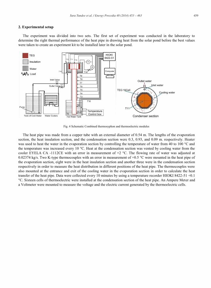
The experiment was divided into two sets. The first set of experiment was conducted in the laboratory to determine the right thermal performance of the heat pipe in drawing heat from the solar pond before the best values were taken to create an experiment kit to be installed later in the solar pond.
Fig. 4 Schematic Combined thermosyphon and thermoelectric modules
The heat pipe was made from a copper tube with an external diameter of 0.54 m. The lengths of the evaporation section, the heat insulation section, and the condensation section were 0.3, 0.93, and 0.09 m. respectively. Heater was used to heat the water in the evaporation section by controlling the temperature of water from 40 to 100 °C and the temperature was increased every 10 °C. Heat at the condensation section was vented by cooling water from the cooler EYELA CA -1112CE with an error in measurement of +2 °C. The flowing rate of water was adjusted at 0.02374 kg/s. Two K-type thermocouples with an error in measurement of +0.5 °C were mounted in the heat pipe of the evaporation section, eight were in the heat insulation section and another three were in the condensation section respectively in order to measure the heat distribution in different positions of the heat pipe. The thermocouples were also mounted at the entrance and exit of the cooling water in the evaporation section in order to calculate the heat transfer of the heat pipe. Data were collected every 10 minutes by using a temperature recorder HIOKI 8422-51 +0.1 °C. Sixteen cells of thermoelectric were installed at the condensation section of the heat pipe. An Ampere Meter and a Voltmeter were mounted to measure the voltage and the electric current generated by the thermoelectric cells.

460 Sura Tundee et al. / Energy Procedia 48 ( 2014 ) 453 – 463
Fig.5.Combined thermosyphon and thermoelectric modules test rig.
The heat pipe was installed into the solar pond (Fig.5). The pipe was made from a copper tube with an external diameter of 0.54 m. The lengths of the evaporation section, the heat insulation section, and the condensation section were 0.5, 0.73, and 0.09 m. respectively. The heat receiving part of the heat pipe was installed in the section where there was no heat convection in the solar pond. The heat insulation section was installed in the layer where there was also no heat convection and the section itself was insulated in order to prevent heat convection from the heat pipe. The condensation section was mounted in the upper heat convection by using R134a as the working fluid. The K-type thermocouples with an error in measurement of +0.5 °C were mounted on the heat pipe at an interval of 0.125 m. from the evaporation section to the condensation section. The thermocouples were also installed in the solar pond at an interval of 0.1 m. from the bottom ground to the upper heat convection layer in order to measure the heat accumulated within the solar pond. Data were collected every 10 minutes by using a temperature recorder HIOKI 8422-51 +0.1 °C. with 32 channels. Sixteen thermoelectric cells were installed in the solar pond at the condensation section. An Ampere Meter and a Voltmeter were also in place to measure the voltage and the eclectic current generated by the thermoelectric. 3. Results and discussions
3.1 Laboratory testing and results
Fig.6.The distribution of temperature on the length of the heat pipe
Sura Tundee et al. / Energy Procedia 48 ( 2014 ) 453 – 463 461
Fig. 6 showed the distribution of temperature on the length of the heat pipe. To study its performance in transferring the heat, the pipe was divided into three parts; the evaporation section, the heat insulation section, and the condensation section with 0.30, 0.93, and 0.09 m. in diameter respectively. In the experiment, the flowing rate of cooling water was controlled at 0.02374 Kg/s. The temperature of cooling water at the condensation section was 10 °C. The results showed that when the temperature at the evaporation section increased, heat transfer of the heat pipe increased accordingly as the evaporation section received much heat hence making the working fluid inside the heat pipe change its status into steam moving to transfer more heat at the condensation section. This could be noticed that when the temperature at the evaporation section increased, the temperature at the condensation section was similar to that of the evaporation section. When the temperature at the evaporation section was over 70 °C, the rate of heat transfer decreased when compared to the increased temperature in the evaporation section. This was due to the insufficiency of working fluid moving to fill the evaporation section but was blocked by the vapor bubbles that were moving to cool the condensation section. In the experiment, the right temperature at the evaporation section had a good rate of heat exchange at 70 °C.
(a) (b)
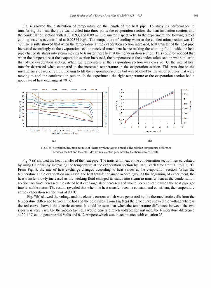
Fig.7.(a)The relation heat transfer rate of thermosyphon versus time;(b) The relation temperature difference between the hot and the cold sides versus electric generated by the thermoelectric cells.
Fig. 7 (a) showed the heat transfer of the heat pipe. The transfer of heat at the condensation section was calculated
by using Calorific by increasing the temperature at the evaporation section by 10 °C each time from 40 to 100 °C. From Fig. 8, the rate of heat exchange changed according to heat values at the evaporation section. When the temperature at the evaporation increased, the heat transfer changed accordingly. At the beginning of experiment, the heat transfer slowly increased as the working fluid changed its status into steam to transfer heat at the condensation section. As time increased, the rate of heat exchange also increased and would become stable when the heat pipe got into its stable status. The results revealed that when the heat transfer became constant and consistent, the temperature at the evaporation section was at 90 °C.
Fig. 7(b) showed the voltage and the electric current which were generated by the thermoelectric cells from the temperature difference between the hot and the cold sides. From Fig.8 (a) the blue curve showed the voltage whereas the red curve showed the electric current. It could be seen that when the temperature difference between the two sides was very vary, the thermoelectric cells would generate much voltage; for instance, the temperature difference at 20.1 °C could generate 4.6 Volts and 0.12 Ampere which was in accordance with equation 23.

462 Sura Tundee et al. / Energy Procedia 48 ( 2014 ) 453 – 463
3.2 Experimental testing and results
(a) (b)
Fig.8 (a)The relation the temperature versus the length of thermosyphon; (b)The relation between electric generated by the thermoelectric cells versus time.
Fig. 8 (a) showed the relation between the temperature of the thermosyphon pipe and the length of the heat pipe.
The experiment was conducted three times. The first experiment was carried out with the temperature of under heat convection at 35.9 °C, the green curve, the temperature for evaporation at 33 °C, the temperature for condensation at 30.9 °C, and the temperature difference between the two sides at 2.1 °C. The second experiment was conducted by using the temperature of under heat convection at 38.7°C, the temperature for evaporation at 36.6 °C, the temperature for condensation at 31.6 °C, and the temperature difference between the two sides at 5 °C. Finally, the third experiment showed that the temperature difference between the two sides was 3.38 °C. It could be seen from the figures that the heat pipe could draw heat from the evaporation section to transfer heat at the condensation section without the change of temperature at the heat insulation section.
Fig. 8 (b) showed the relation between the voltage and the time. From this figure, it could be seen that the voltage generated by the thermoelectric cells changed according to the time and the temperature difference of the two sides of the heat pipe. The temperature on the hot side of the thermoelectric cells was dependent on the temperature of the under heat convection layer of the solar pond whereas the temperature on the cold side was dependent on the temperature of the upper heat convection layer of the solar pond. From the red and blue curves, it could be seen that at 07:00 hr., the voltage generated increased and would decrease when the temperature in the upper heat convection layer increased and the voltage would increase when the temperature in the under heat convection layer increased at 15:00 hr.
4. Conclusions
This article suggests that installing the thermosyphon heat pipe in the solar pond to draw heat from the heat convection layer and transfer it to the thermoelectric cells is appropriate. The voltage generated by the thermoelectric cells is dependent on the temperature difference between the hot and the cold sides of the thermoelectric cells. When the difference very varies, the thermoelectric cells can generate much voltage. The temperature difference of the two sides is also dependent on the temperature of the under heat convection layer which acts as a heat source for the thermosyphon heat pipe. And the temperature at the upper heat convection acts also as a heat transfer for the thermoelectric cells (as demonstrated in the experiment at 07:00 hr. where the highest voltage of 234.25 millivolts was generated and was slowly decreasing later as the temperature at the upper heat convection layer increased from 30 to 34 °C resulting in less temperature difference between the two sides and hence making the thermoelectric cells generate less voltage accordingly.
Sura Tundee et al. / Energy Procedia 48 ( 2014 ) 453 – 463 463
Acknowledgments
The authors would like to express Their appreciation to the Rajamangala University of Technology Isan and Research& Development Institute, Faculty of engineering Rajamangala Rajamangala University of Technology Isan Khon Kaen Campus for providing financial support for attending International Conference on Solar Heating and Cooling for Building and industry (SHC 2013)
References
[1] Akbarzadeh, A, Andrews, J, and Golding, P. Solar Pond Technologies: A Review and Future Directions, Chapter 7, Advances in Solar Energy, EARTHSCAN.2005.
[2] Andrew, j., Akbarzadeh, A.,Enhancing the thermal efficiency of solar pond by extracting heat from the gradien layer,Solar Energy,2005;78:704 -716.
[3] Dunn, P. D, and Reay, D. A. 1994. Heat Pipes, Pergamon, Fourth Edition [4] ESDU, Engineering Sciences Data 81038.Heat Pipe-performance of Two-Phas Closed Thermosyphon.1981. [5] Faghri, A. Heat Pipe Science and Technology, DC, Taylor & Francis.1985. [6] Ha, B. 1984. Ormat Turbines, Arava Solar Pond Inaugurated, Sunworld.1984;8(1) 18 [7] Tabor, H and Doron, B. Solar Ponds- Lessons learned from the 150 kW(e) power plant at Ein Boqek, Proc. of the ASME Solar Energy
Div.,Anaheim, California.1986. [8] Randeep Singh, Sura Tundee, Aliakba Akbarzadeh,2010.Electric power generation from solar pond using combined thermosyphon and
thermoelectric modules.Mechanical and Manufacturing Engineering, RMIT University, Solar Energy,2011;85:371 -378. [9] Rowe, D. M.CRC Handbook of Thermoelectrics, CRC Press.1995. [10] KRYOTHERM, 6 Aerodromnaya Street, Saint-Petersburg, 197348, Russia, Tel.: (812) 394-1310, Email: [email protected]
http;//www.kryotherm.ru
Related Documents


![Modeling Of A Solar Pond For Different Insulation ... · Sakhrieh and Al-Salaymeh [3] studied both experimental and numerical parts of solar pond performance under Jordanian climate](https://static.cupdf.com/doc/110x72/6073569726559227a83396ae/modeling-of-a-solar-pond-for-different-insulation-sakhrieh-and-al-salaymeh-3.jpg)
