Page | 1 Electric Circuits Vocabulary Term Definition Electric Current The flow of electric charge. Electric Circuit Any complete path through which electricity travels. Closed Circuit A circuit in which there is a complete path for electricity to flow. Open Circuit A circuit in which there is a break so current can not flow. Conductors A material that easily carries electrical current. Insulators A material that poorly conducts electrical current or heat. Ohm’s Law • Current • Voltage • Resistance A formula that says the current flowing in a circuit is the voltage divided by the resistance. V = IR Series Circuit A circuit that has only one path for current to flow through. Parallel Circuit A circuit that has multiple paths for the current to flow through.

Welcome message from author
This document is posted to help you gain knowledge. Please leave a comment to let me know what you think about it! Share it to your friends and learn new things together.
Transcript
Page | 1
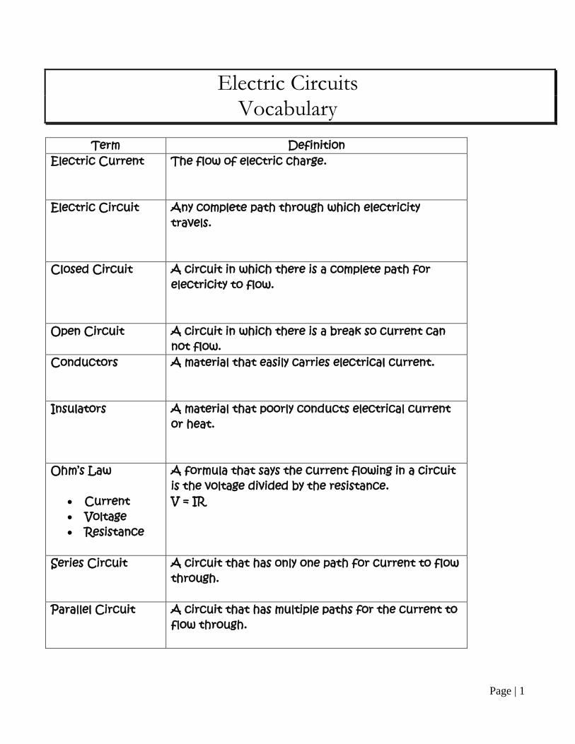
Electric Circuits Vocabulary
Term Definition
Electric Current The flow of electric charge.
Electric Circuit Any complete path through which electricity travels.
Closed Circuit A circuit in which there is a complete path for electricity to flow.
Open Circuit
A circuit in which there is a break so current can not flow.
Conductors
A material that easily carries electrical current.
Insulators A material that poorly conducts electrical current or heat.
Ohm’s Law
• Current • Voltage • Resistance
A formula that says the current flowing in a circuit is the voltage divided by the resistance. V = IR
Series Circuit
A circuit that has only one path for current to flow through.
Parallel Circuit
A circuit that has multiple paths for the current to flow through.
Page | 2
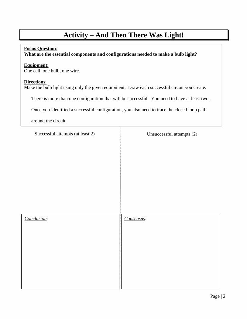
Activity – And Then There Was Light!
Focus Question: What are the essential components and configurations needed to make a bulb light? Equipment: One cell, one bulb, one wire. Directions: Make the bulb light using only the given equipment. Draw each successful circuit you create.
There is more than one configuration that will be successful. You need to have at least two.
Once you identified a successful configuration, you also need to trace the closed loop path
around the circuit.
Unsuccessful attempts (2) Successful attempts (at least 2)
Conclusion: Consensus:

Page | 3
Symbols Used in Basic Circuits
Sketch a circuit with 2 resistors, a light bulb and a single cell battery. Sketch a circuit with 3 light bulbs, an open switch, and a single cell battery.
Page | 4
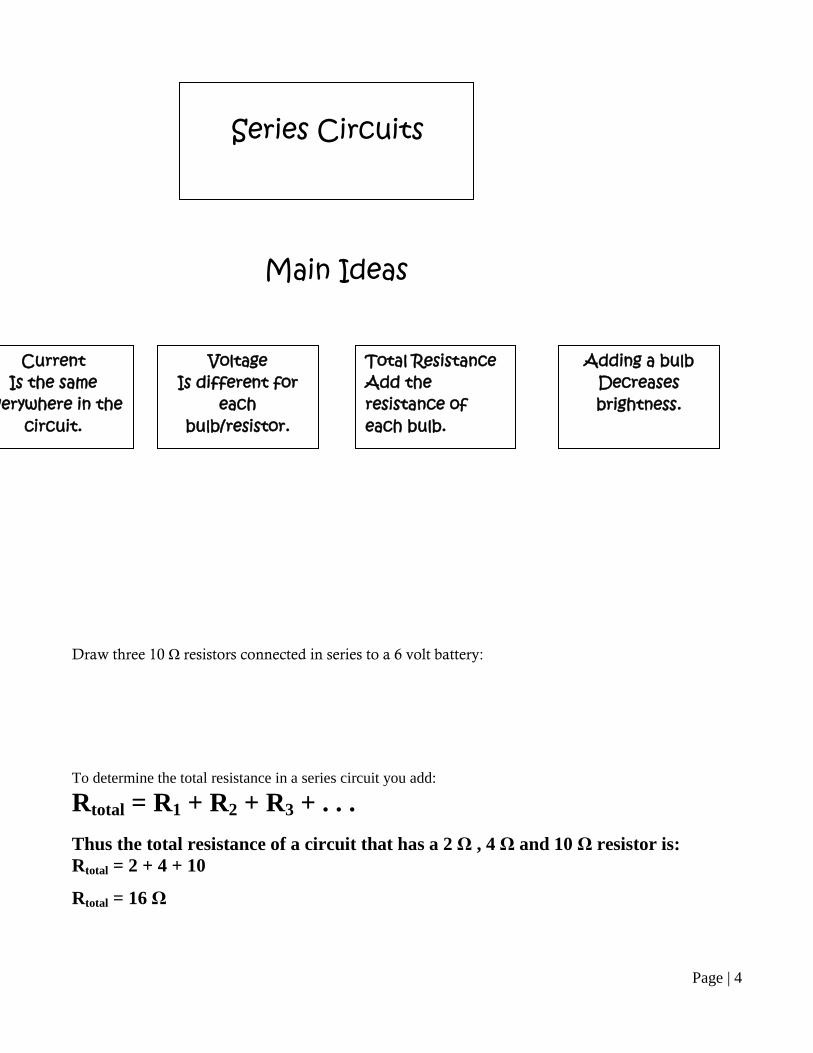
Draw three 10 Ω resistors connected in series to a 6 volt battery: To determine the total resistance in a series circuit you add:
Rtotal = R1 + R2 + R3 + . . . Thus the total resistance of a circuit that has a 2 Ω , 4 Ω and 10 Ω resistor is: Rtotal = 2 + 4 + 10
Rtotal = 16 Ω
Series Circuits
Main Ideas
Current Is the same
verywhere in the circuit.
Voltage Is different for
each bulb/resistor.
Total Resistance Add the resistance of each bulb.
Adding a bulb Decreases brightness.
Page | 5
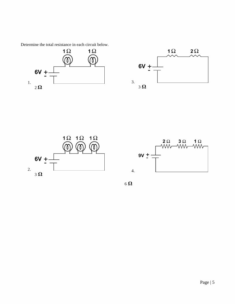
Determine the total resistance in each circuit below.
1. 2 Ω
2. 3 Ω
3. 3 Ω
4. 6 Ω
Page | 6
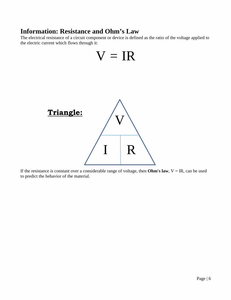
Information: Resistance and Ohm’s Law The electrical resistance of a circuit component or device is defined as the ratio of the voltage applied to the electric current which flows through it:
V = IR Triangle:
If the resistance is constant over a considerable range of voltage, then Ohm's law, V = IR, can be used to predict the behavior of the material.
V
I R
Page | 7
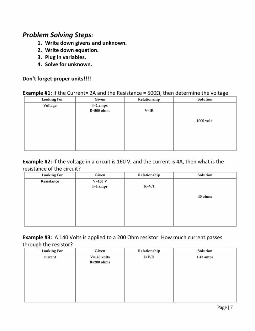
Problem Solving Steps: 1. Write down givens and unknown. 2. Write down equation. 3. Plug in variables. 4. Solve for unknown.
Don’t forget proper units!!!! Example #1: If the Current= 2A and the Resistance = 500Ω, then determine the voltage.
Looking For Given Relationship Solution Voltage I=2 amps
R=500 ohms
V=IR
1000 volts
Example #2: If the voltage in a circuit is 160 V, and the current is 4A, then what is the resistance of the circuit?
Looking For Given Relationship Solution Resistance V=160 V
I=4 amps
R=V/I
40 ohms
Example #3: A 140 Volts is applied to a 200 Ohm resistor. How much current passes through the resistor?
Looking For Given Relationship Solution current V=140 volts
R=200 ohms I=V/R
1.43 amps
Page | 8
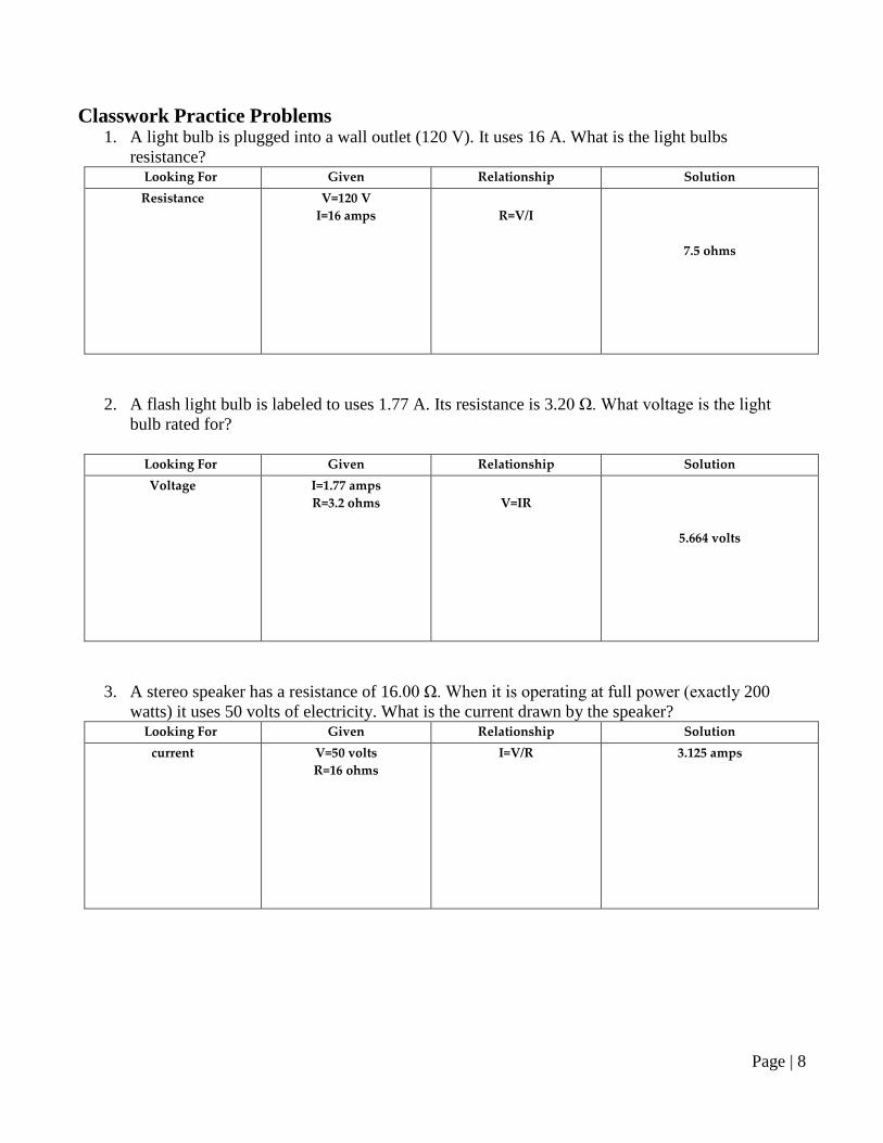
Classwork Practice Problems 1. A light bulb is plugged into a wall outlet (120 V). It uses 16 A. What is the light bulbs
resistance? Looking For Given Relationship Solution Resistance V=120 V
I=16 amps
R=V/I
7.5 ohms
2. A flash light bulb is labeled to uses 1.77 A. Its resistance is 3.20 Ω. What voltage is the light bulb rated for?
Looking For Given Relationship Solution Voltage I=1.77 amps
R=3.2 ohms
V=IR
5.664 volts
3. A stereo speaker has a resistance of 16.00 Ω. When it is operating at full power (exactly 200 watts) it uses 50 volts of electricity. What is the current drawn by the speaker?
Looking For Given Relationship Solution current V=50 volts
R=16 ohms I=V/R
3.125 amps
Page | 9
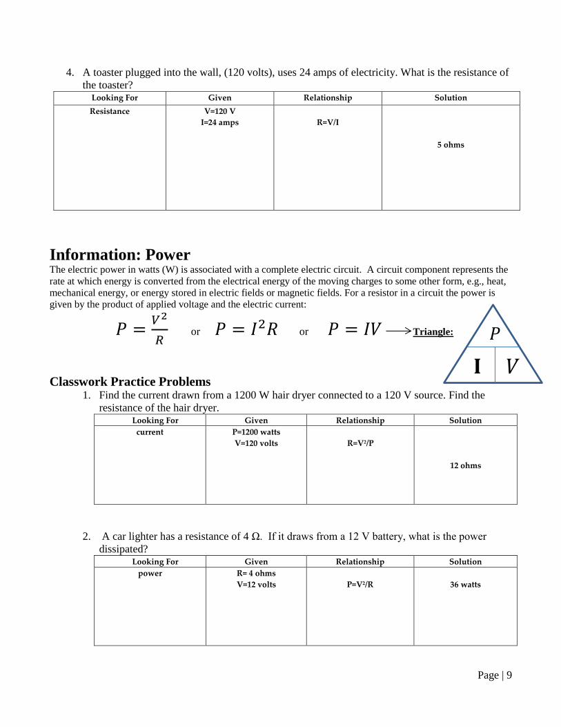
4. A toaster plugged into the wall, (120 volts), uses 24 amps of electricity. What is the resistance of the toaster?
Looking For Given Relationship Solution Resistance V=120 V
I=24 amps
R=V/I
5 ohms
Information: Power The electric power in watts (W) is associated with a complete electric circuit. A circuit component represents the rate at which energy is converted from the electrical energy of the moving charges to some other form, e.g., heat, mechanical energy, or energy stored in electric fields or magnetic fields. For a resistor in a circuit the power is given by the product of applied voltage and the electric current:
𝑃 = 𝑉2
𝑅 or 𝑃 = 𝐼2𝑅 or 𝑃 = 𝐼𝑉 Triangle:
Classwork Practice Problems
1. Find the current drawn from a 1200 W hair dryer connected to a 120 V source. Find the resistance of the hair dryer.
Looking For Given Relationship Solution current P=1200 watts
V=120 volts
R=V2/P
12 ohms
2. A car lighter has a resistance of 4 Ω. If it draws from a 12 V battery, what is the power dissipated?
Looking For Given Relationship Solution power R= 4 ohms
V=12 volts
P=V2/R
36 watts
𝑃
𝐈 𝑉
Page | 10
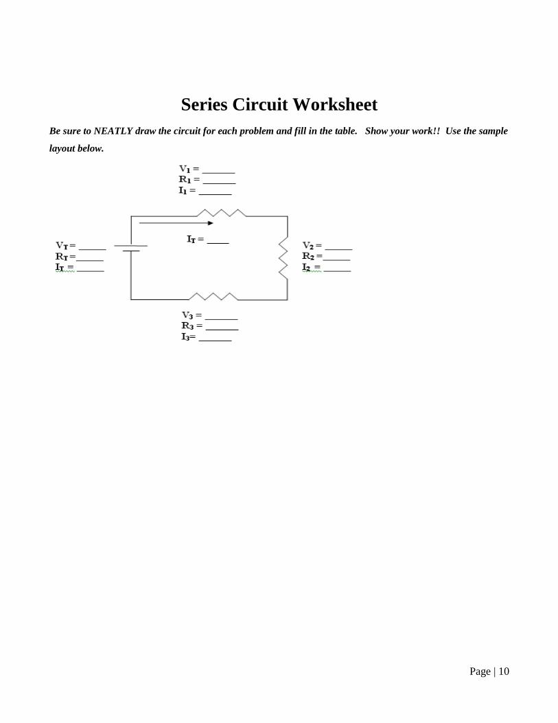
Series Circuit Worksheet
Be sure to NEATLY draw the circuit for each problem and fill in the table. Show your work!! Use the sample
layout below.
Page | 11
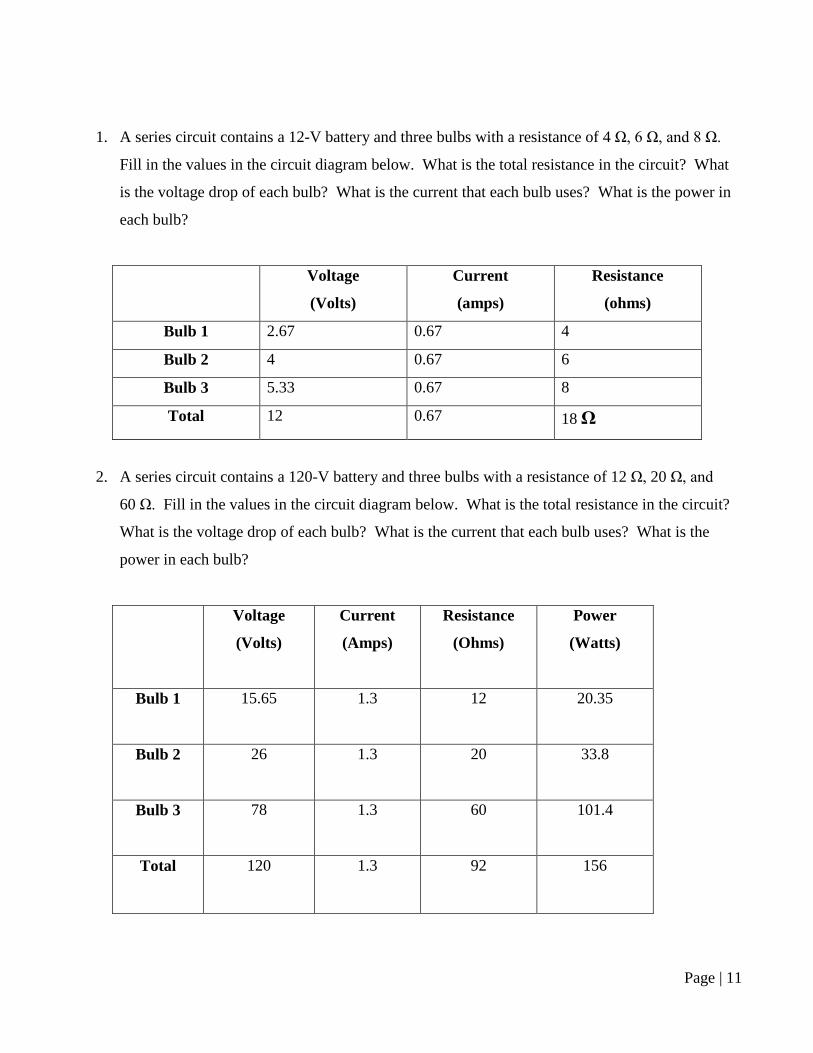
1. A series circuit contains a 12-V battery and three bulbs with a resistance of 4 Ω, 6 Ω, and 8 Ω.
Fill in the values in the circuit diagram below. What is the total resistance in the circuit? What
is the voltage drop of each bulb? What is the current that each bulb uses? What is the power in
each bulb?
Voltage
(Volts)
Current
(amps)
Resistance
(ohms)
Bulb 1 2.67 0.67 4
Bulb 2 4 0.67 6
Bulb 3 5.33 0.67 8
Total 12 0.67 18 Ω
2. A series circuit contains a 120-V battery and three bulbs with a resistance of 12 Ω, 20 Ω, and
60 Ω. Fill in the values in the circuit diagram below. What is the total resistance in the circuit?
What is the voltage drop of each bulb? What is the current that each bulb uses? What is the
power in each bulb?
Voltage
(Volts)
Current
(Amps)
Resistance
(Ohms)
Power
(Watts)
Bulb 1 15.65 1.3 12 20.35
Bulb 2 26 1.3 20 33.8
Bulb 3 78 1.3 60 101.4
Total 120 1.3 92 156
Page | 12
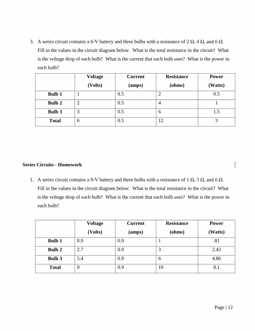
3. A series circuit contains a 6-V battery and three bulbs with a resistance of 2 Ω, 4 Ω, and 6 Ω.
Fill in the values in the circuit diagram below. What is the total resistance in the circuit? What
is the voltage drop of each bulb? What is the current that each bulb uses? What is the power in
each bulb?
Voltage
(Volts)
Current
(amps)
Resistance
(ohms)
Power
(Watts)
Bulb 1 1 0.5 2 0.5
Bulb 2 2 0.5 4 1
Bulb 3 3 0.5 6 1.5
Total 6 0.5 12 3
Series Circuits - Homework
1. A series circuit contains a 9-V battery and three bulbs with a resistance of 1 Ω, 3 Ω, and 6 Ω.
Fill in the values in the circuit diagram below. What is the total resistance in the circuit? What
is the voltage drop of each bulb? What is the current that each bulb uses? What is the power in
each bulb?
Voltage
(Volts)
Current
(amps)
Resistance
(ohms)
Power
(Watts)
Bulb 1 0.9 0.9 1 .81
Bulb 2 2.7 0.9 3 2.43
Bulb 3 5.4 0.9 6 4.86
Total 9 0.9 10 8.1

Page | 13
2. A series circuit contains a 60-V battery and three bulbs with a resistance of 5 Ω, 10 Ω, and 15 Ω.
Fill in the values in the circuit diagram below. What is the total resistance in the circuit? What
is the voltage drop of each bulb? What is the current that each bulb uses? What is the power in
each bulb?
Voltage
(Volts)
Current
(amps)
Resistance
(ohms)
Power
(Watts)
Bulb 1 10 2 5 20
Bulb 2 20 2 10 40
Bulb 3 30 2 15 60
Total 60 2 30 120
Page | 14
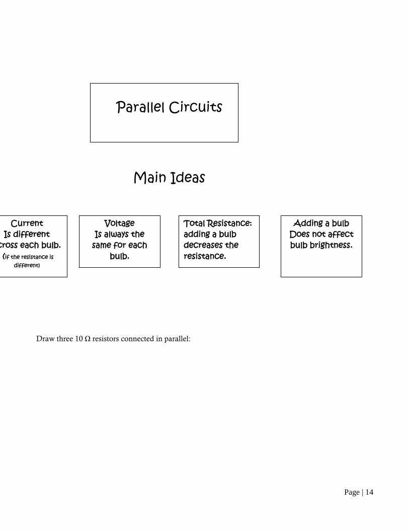
Draw three 10 Ω resistors connected in parallel:
Parallel Circuits
Main Ideas
Current Is different
cross each bulb. (if the resistance is
different)
Voltage Is always the
same for each bulb.
Total Resistance: adding a bulb decreases the resistance.
Adding a bulb Does not affect bulb brightness.
Page | 15
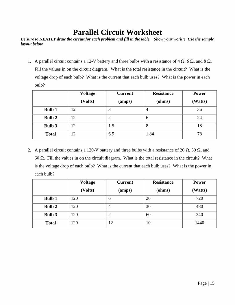
Parallel Circuit Worksheet Be sure to NEATLY draw the circuit for each problem and fill in the table. Show your work!! Use the sample layout below.
1. A parallel circuit contains a 12-V battery and three bulbs with a resistance of 4 Ω, 6 Ω, and 8 Ω.
Fill the values in on the circuit diagram. What is the total resistance in the circuit? What is the
voltage drop of each bulb? What is the current that each bulb uses? What is the power in each
bulb?
Voltage
(Volts)
Current
(amps)
Resistance
(ohms)
Power
(Watts)
Bulb 1 12 3 4 36
Bulb 2 12 2 6 24
Bulb 3 12 1.5 8 18
Total 12 6.5 1.84 78
2. A parallel circuit contains a 120-V battery and three bulbs with a resistance of 20 Ω, 30 Ω, and
60 Ω. Fill the values in on the circuit diagram. What is the total resistance in the circuit? What
is the voltage drop of each bulb? What is the current that each bulb uses? What is the power in
each bulb?
Voltage
(Volts)
Current
(amps)
Resistance
(ohms)
Power
(Watts)
Bulb 1 120 6 20 720
Bulb 2 120 4 30 480
Bulb 3 120 2 60 240
Total 120 12 10 1440
Page | 16
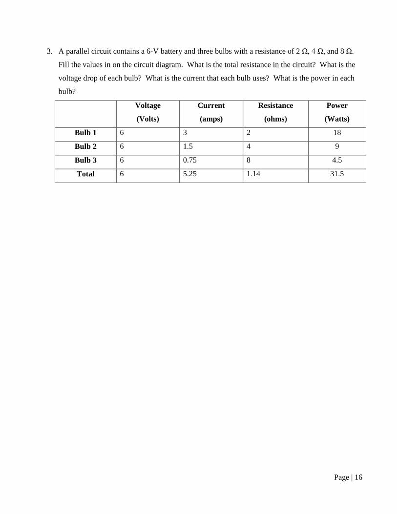
3. A parallel circuit contains a 6-V battery and three bulbs with a resistance of 2 Ω, 4 Ω, and 8 Ω.
Fill the values in on the circuit diagram. What is the total resistance in the circuit? What is the
voltage drop of each bulb? What is the current that each bulb uses? What is the power in each
bulb?
Voltage
(Volts)
Current
(amps)
Resistance
(ohms)
Power
(Watts)
Bulb 1 6 3 2 18
Bulb 2 6 1.5 4 9
Bulb 3 6 0.75 8 4.5
Total 6 5.25 1.14 31.5

Page | 17
Parallel Circuit Homework
1. A parallel circuit contains a 20-V battery and three bulbs with a resistance of 2 Ω, 4 Ω, and 6 Ω.
Fill the values in on the circuit diagram. What is the total resistance in the circuit? What is the
voltage drop of each bulb? What is the current that each bulb uses? What is the power in each
bulb?
Voltage
(Volts)
Current
(amps)
Resistance
(ohms)
Power
(Watts)
Bulb 1 20 10 2 200
Bulb 2 20 5 4 100
Bulb 3 20 3.33 6 66.7
Total 20 18.33 1.09 366.7
2. A parallel circuit contains a 60-V battery and three bulbs with a resistance of 5 Ω, 10 Ω, and
15 Ω. Fill the values in on the circuit diagram. What is the total resistance in the circuit? What
is the voltage drop of each bulb? What is the current that each bulb uses? What is the power in
each bulb?
Voltage
(Volts)
Current
(amps)
Resistance
(ohms)
Power
(Watts)
Bulb 1 60 12 5 720
Bulb 2 60 6 10 360
Bulb 3 60 4 15 240
Total 60 22 2.72 1320
Page | 18
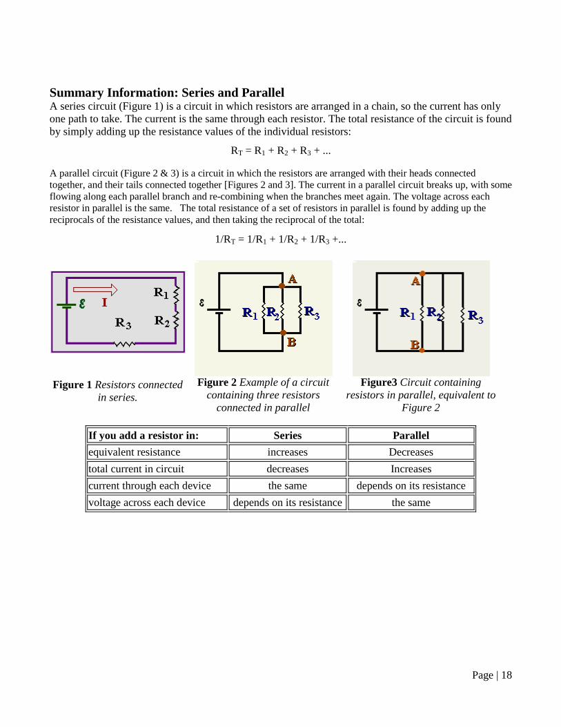
Summary Information: Series and Parallel A series circuit (Figure 1) is a circuit in which resistors are arranged in a chain, so the current has only one path to take. The current is the same through each resistor. The total resistance of the circuit is found by simply adding up the resistance values of the individual resistors:
RT = R1 + R2 + R3 + ... A parallel circuit (Figure 2 & 3) is a circuit in which the resistors are arranged with their heads connected together, and their tails connected together [Figures 2 and 3]. The current in a parallel circuit breaks up, with some flowing along each parallel branch and re-combining when the branches meet again. The voltage across each resistor in parallel is the same. The total resistance of a set of resistors in parallel is found by adding up the reciprocals of the resistance values, and then taking the reciprocal of the total:
1/RT = 1/R1 + 1/R2 + 1/R3 +...
Figure 1 Resistors connected in series.
Figure 2 Example of a circuit
containing three resistors connected in parallel
Figure3 Circuit containing
resistors in parallel, equivalent to Figure 2
If you add a resistor in: Series Parallel equivalent resistance increases Decreases total current in circuit decreases Increases current through each device the same depends on its resistance voltage across each device depends on its resistance the same
Related Documents


