Babrauskas, V., Electric Arc Explosions, pp. 1283-1296 in Interflam 2010—Proc. 12 th Intl. Conf., Interscience Communications Ltd, London (2010). 1283 ELECTRIC ARC EXPLOSIONS Vytenis Babrauskas, Ph.D. Fire Science and Technology Inc. 9000 – 300 th Place S.E., Issaquah WA 98027, USA Abstract When an electric arc is created, a pressure event occurs. There can be two aspects to this: the shock and sound waves propagated from the expanding arc channel, and the bulk pressurization of the en- closure, if arcing is taking place within a closed volume. The present paper is the first systematic re- view of the research on both these pressure phenomena. Quantitative studies on electrical arc explo- sion pressures date back to the 1920s, although arc pressures generated by lightning, which is a type of electric arc discharge, have been studied since the 1700s, but understanding of the phenomena is still not complete or exhaustive. Experimental data are compared to theoretical predictions. It is shown that in an enclosed volume some extremely high pressures can be generated, if the arc current is sufficient. Such pressures can destroy buildings and mechanical equipment and cause injuries or death to nearby individuals. Even without enclosures, the shock waves produced from high energy arcs can cause injuries, although arc flash injury may be of greater concern. Injury potential generally requires that high currents be available, and serious damages or injuries are not associated with low- energy arcing occurrences. Keywords: arc pressure, electric arcs, electrical accidents, explosions, shock waves, switchgear. Introduction Electric arcing in circuits with sizable maximum short-circuit current capacity can be a highly ener- getic effect. In fact, buildings have collapsed due to arc pressure, since in an enclosed space some surprisingly large pressures can be built up. ‘Arc flash’ is the thermal radiation component associated with energetic electric arcs, and it has received a great deal of study in recent years since thermal ra- diation has been a cause of serious burn injuries to electricians 1 . Consequently, computational meth- ods and research have focused on the design of appropriate protective clothing. For arc pressures, however, no comparable activity has taken place. In fact, the literature is sparse and not systematic on this topic. It is the purpose of this paper to provide the first-ever review of electric arc explosions. The emphasis is placed on pressures developed and on the calculational methods available for these, along with experimental data that have been published. Some of the results are strikingly high. For instance, in one test explosion overpressures of 83 atm were obtained. The magnitude of this can best be appre- ciated by considering that a fuel-air deflagration will typically attain only around 7 – 8 atm, barring pressure-piling effects or other turbulence enhancements. During normal operation of a circuit break- er, arc pressures of roughly 3 atm magnitude can be expected 2 , but these devices are designed to sus- tain the pressures generated by the normal arcing associated with circuit opening. With regards to the energy supplying the arc, arcs can be of three types: (1) discharge of a fixed amount of stored energy (e.g., a capacitor; a current transformer); (2) DC power sources; or (3) AC power sources. Lightning strikes are the most important form of stored energy discharge, since ca- pacitive discharge tends to be confined to specialized situations and is uncommon as a source of in- dustrial accidents. Since most of the power transmission and distribution networks are AC, the bulk of the research available has focused on AC arcs. But heavy-power DC systems also exist and are im- portant in certain industries (e.g., electric train propulsion). DC arc explosions are fundamentally dif- ferent since there is no ‘zero-crossing’ in DC. In AC circuits, an arc will extinguish at 2× the power frequency (e.g., at 100 or 120 Hz), although it may reignite very shortly afterwards. In DC circuits, this extinguishing characteristic does not exist, and arcs will generally extinguish only due to external circuit interruption or due to excessive electrode consumption. Most aspects of arc behavior only de- pend on arc current and arc power, and not on the type of power supply, but where the type of power supply does matter, this will be considered. The discharge of a fixed amount of energy is termed a

Welcome message from author
This document is posted to help you gain knowledge. Please leave a comment to let me know what you think about it! Share it to your friends and learn new things together.
Transcript

Babrauskas, V., Electric Arc Explosions, pp. 1283-1296 in Interflam 2010—Proc. 12th Intl. Conf., Interscience Communications Ltd, London (2010).
1283
ELECTRIC ARC EXPLOSIONS Vytenis Babrauskas, Ph.D.
Fire Science and Technology Inc. 9000 – 300th Place S.E., Issaquah WA 98027, USA
Abstract When an electric arc is created, a pressure event occurs. There can be two aspects to this: the shock and sound waves propagated from the expanding arc channel, and the bulk pressurization of the en-closure, if arcing is taking place within a closed volume. The present paper is the first systematic re-view of the research on both these pressure phenomena. Quantitative studies on electrical arc explo-sion pressures date back to the 1920s, although arc pressures generated by lightning, which is a type of electric arc discharge, have been studied since the 1700s, but understanding of the phenomena is still not complete or exhaustive. Experimental data are compared to theoretical predictions. It is shown that in an enclosed volume some extremely high pressures can be generated, if the arc current is sufficient. Such pressures can destroy buildings and mechanical equipment and cause injuries or death to nearby individuals. Even without enclosures, the shock waves produced from high energy arcs can cause injuries, although arc flash injury may be of greater concern. Injury potential generally requires that high currents be available, and serious damages or injuries are not associated with low-energy arcing occurrences.
Keywords: arc pressure, electric arcs, electrical accidents, explosions, shock waves, switchgear.
Introduction Electric arcing in circuits with sizable maximum short-circuit current capacity can be a highly ener-getic effect. In fact, buildings have collapsed due to arc pressure, since in an enclosed space some surprisingly large pressures can be built up. ‘Arc flash’ is the thermal radiation component associated with energetic electric arcs, and it has received a great deal of study in recent years since thermal ra-diation has been a cause of serious burn injuries to electricians1. Consequently, computational meth-ods and research have focused on the design of appropriate protective clothing. For arc pressures, however, no comparable activity has taken place. In fact, the literature is sparse and not systematic on this topic. It is the purpose of this paper to provide the first-ever review of electric arc explosions. The emphasis is placed on pressures developed and on the calculational methods available for these, along with experimental data that have been published. Some of the results are strikingly high. For instance, in one test explosion overpressures of 83 atm were obtained. The magnitude of this can best be appre-ciated by considering that a fuel-air deflagration will typically attain only around 7 – 8 atm, barring pressure-piling effects or other turbulence enhancements. During normal operation of a circuit break-er, arc pressures of roughly 3 atm magnitude can be expected2, but these devices are designed to sus-tain the pressures generated by the normal arcing associated with circuit opening. With regards to the energy supplying the arc, arcs can be of three types: (1) discharge of a fixed amount of stored energy (e.g., a capacitor; a current transformer); (2) DC power sources; or (3) AC power sources. Lightning strikes are the most important form of stored energy discharge, since ca-pacitive discharge tends to be confined to specialized situations and is uncommon as a source of in-dustrial accidents. Since most of the power transmission and distribution networks are AC, the bulk of the research available has focused on AC arcs. But heavy-power DC systems also exist and are im-portant in certain industries (e.g., electric train propulsion). DC arc explosions are fundamentally dif-ferent since there is no ‘zero-crossing’ in DC. In AC circuits, an arc will extinguish at 2× the power frequency (e.g., at 100 or 120 Hz), although it may reignite very shortly afterwards. In DC circuits, this extinguishing characteristic does not exist, and arcs will generally extinguish only due to external circuit interruption or due to excessive electrode consumption. Most aspects of arc behavior only de-pend on arc current and arc power, and not on the type of power supply, but where the type of power supply does matter, this will be considered. The discharge of a fixed amount of energy is termed a

1284
spark, while a sustained discharge is an arc, but again this distinction will generally be seen not to affect the analysis of results. Arc explosions are not rare in industry, and in other situations where 480 volt, or higher, voltages are utilized, but published case histories are scarce. Neither of the two large electrical accident compila-tions3,4 mentions the subject. Lee5 published four brief case histories, Crawford et al.6 documented seven case histories of arc explosions inside motor terminal boxes, include one fatality, while Heber-lein et al.7 described two non-fatal explosions inside motor control centers. The best-known incident was in an Atlanta high-rise building that took place on 30 June 1989. The fumbling of an electrician replacing a fuse caused a 480 VAC bus duct explosion8 and the explosion and subsequent fire led to five fatalities. Lightning strikes can lead to arc explosions in any type of premises. In 1773, Lind demonstrated that if a conductor from a lightning arrester is run down through a house, but with a small gap in this conductor, this can form a spark gap and a strike to the arrester can result in an arc explosion capable of destroying the house9. Individuals have been bodily knocked over when in prox-imity both to electrical fault arcs and lightning strikes, although interestingly often there have been negligible injuries to the individual knocked over10. But in cases where roofs collapse, the outcome may be traumatic if persons are present underneath. Eardrum rupture can be expected at explosion overpressures of 19 kPa (10% probability) or 45 kPa (50% probability), while death due to lung damage is 120 kPa (10% probability) or 141 kPa (50% probability). The above values come from an extensive statistical study by Eisenberg et al.11; older data are somewhat different, but not greatly. In any case, they indicate that it does not take large over-pressures for injury or death to result from explosion pressures. Only arc explosions in gases will be reviewed here, even though arc explosions in electrical insulating liquids can be of importance and arc explosions underwater are of some specialized interest. Apart from true arc explosions, conventional fuel-air explosions can also arise due to electrical causes. Per-haps the most common type of explosion associated with electricity is where an electric spark ignites a flammable gas mixture or dust cloud. These explosions can be severe and destructive, but are not covered here, because the electric power does not provide the energy for the explosion, instead, it is the chemical oxidation reaction which serves as the energy source. Also excluded are explosions in manholes, underground ducts, and similar installations which may entail both fuel-air explosion and arc explosion components. Transformer explosions12 also involve some arc explosions aspects, but they are typically complicated and will likewise not be covered here. An arc explosion arises due a very rapid heating of air or other medium. In the process, electrical en-ergy is converted into other forms of energy: dissociation (breaking up of molecules, e.g., separating O2 into 2O), ionization, and heating of the gas, including its compression; thermal radiation; and con-duction losses into adjacent solids such as electrodes. In addition, some electrode metal is vaporized and this contributes to the total volume which is being explosively heated, yet, the role of chemical reactions has only recently been explored. Thunder is an acoustic manifestation of an electric arc ex-plosion and has been studied for centuries (the currents involved in a lightning discharge are typically 20 – 200 kA, which is in the same range as for serious industrial electric arc accidents). Yet only in the last decade has there been some understanding achieved of the relative importance of the mecha-nisms involved, primarily due to Graneau and coworkers13. They demonstrated that thunder could not be adequately explained by thermal or electrodynamic effects, and this conclusion would pertain to arc explosions in general. In one experiment, they used an 8 µs duration capacitive discharge and showed that the energy measured from the arc was 124% of the energy stored in the capacitor. The 24% gain was not a measurement error, but represented chemical energy liberated by breaking chemi-cal bonds. Specific pathways were found to include dissociating N2 and O2 molecules into atoms, then forming products such as O3 and NOX. Researchers have generally ignored the need to account for stored chemical energy, thus published heat balance calculations are likely to be subject to error, es-pecially for short-duration arcs. Graneau et al. also noted that in the lightning community, high-current, short-duration discharges are termed ‘cold lightning.’ This is not hyperbole and they found that while discharges mechanically tore a piece of paper inserted into the path of the arc, they did not

1285
ignite the paper nor even char it. The paper could be ignited, however, if placed in contact with the electrodes. They also observed that lightning hitting water did not generate steam.
Shock waves generated from electric arcs If in a gaseous medium there is an abrupt change in pressure, temperature, or volume created at some location, a wave will be generated which will propagate through the medium. The wave can be a sound wave, a shock wave, or both, depending on the characteristics of the source. In the case of an electric arc, while a shock wave will be generated and it is audibly perceived as an explosion (unless of very small scale), the shock wave does not constitute a detonation, which would require that the shock wave be supported by an exothermic reaction occurring behind the shock front. For subsonic sound waves in air, the decay in pressure with distance from the source goes as
�
1/ r for the infinite-cylinder geometry and 1/r for the sphere. But for shock waves, these simple wave-equation relation-ships are not applicable. A reasonably short arc will be represented by a short cylinder, but this is not a geometry that lends itself to simple theoretical solutions. Baker presented calculated data on a point sources14, along with experimental data on bursting explosions of short cylindrical vessels15 and spherical vessels15. The curvature in these results (Figure 1) show that, unless only examined over small intervals, the actual relationship is not of a power-law type. In this figure, the non-dimensional scaling variables used are
�
P = Δp / po and
�
R = r / E / po3 , where po = ambient pressure (Pa), r = radi-
us (m), and E = energy (J). But, in addition, it should be noted that the actual shape of the curve will depend on the rate at which the energy is delivered, and this can have a range of variations. Turning now specifically to the electric arc, when breakdown is initiated, a narrow conducting fila-ment first bridges the gap, and then it grows rapidly in diameter until it reaches an ultimate value and the ‘arc channel’ is fully established. In 1936, Suits16 measured pressures and sound waves emitted from the expanding arc channel and determined that there are two components: a sound wave propa-gating at the speed of sound and a shock wave propagating at 2 or 3 times that. He also documented the interesting phenomenon that a shock wave traveling through the air can often extinguish an ongo-ing arc, if it traverses its path. This work was extended by Flowers17, who in 1943 made more detailed measurements and found velocities of 1000 – 2000 m s-1 for the radial expansion of the arc channel. His slowest measured rate of expansion was 460 m s-1, which is still above the 340 m s-1 of sound speed, indicating that shock waves are being generated in all cases. The arc channel eventually reach-es a steady-state diameter and no longer expands, and Flowers found that a time of 3 – 35 µs was re-quired for the final diameter to be attained in his experiments, but the actual value is dependent on external circuit parameters which limit the current growth rate. When the final diameter is achieved, Flowers found that the arc channel cross-sectional area is linearly proportional to the cur-rent, with the proportionality be-ing 11 A mm-2. Later Vanyukov et al. showed that the expanding shock front and the channel are initially of the same diameter, but subsequently the channel typically approaches a maximum diameter, while the shock front continues expanding outwards18 (Figure 2). Intermediate between these is the ‘envelope,’ which is the boundary between compressed gas (outside the boundary) and rarefied gas (inside). In some cases, however, arc channel diameter growth con-
0.001
0.01
0.1
1
10
100
1000
10000
0.01 0.1 1 10 100
P
R
Point source
Cylindrical vessels
Spherical vessels
Figure 1 Shock wave overpressure scaling for several geometries

1286
tinues for a protracted period, especially at higher current values19. Shock wave modeling was not yet existent when Flowers did his study, and it was not until 1951 that Drabkina20 presented results of shock wave modeling of an arc and showed that, for arcs supplied with a small current, the shock wave may only propagate for 25 mm, or so, before the shock magnitude becomes insignificant (Figure 3). Eventually with sufficient dis-tance, any shock wave dissipates into a sound wave. Later, Hill21 modeled the shock wave de-velopment of a 30 kA arc with hydrody-namic calculations. Data were not availa-ble for validation of pressures, but Hill successfully validated the temperature profiles he computed against experi-mental data. Freeman and Craggs22 further continued modeling the shock front development by con-sidering various rates of energy delivery, as a function of time. Graneau9 studied high-current arcs discharged across a small (3.2 mm) gap and found that the shock-front region was wedge-shaped and would not be well modeled as a spherical or a cylindrical source. Thus, a spherical representation cannot be assumed to be well suited under all conditions.
Pressure from arcs in the open Two different conditions have to be considered with regards to pressures produced from arcs. If the arcing is in the open air, or in a large space (e.g., an open factory area), then there will not be a signif-icant pressure rise in the whole volume, but there will be local pressure effects in the vicinity of the arc. Conversely, if arcing is an a switchgear cabinet, a small substation, or a similarly enclosed locale, then significant pressure rise can be experienced throughout the entire volume of this limited space. The main research focus has been on closed volumes and information on arc pressures in the open is limited. Baker14 proposed that arc explosions in large enclosures or in the open can be treated using some re-sults from acoustical theory. The pressure rise
�
Δp = p1 − po( ) is as-sumed to be due to the arc effec-tively generating a certain volume V of air at the ambient density ρo. Then from acoustical theory, the pressure rise at any particular dis-tance r (m) from the arc is:
( )rtVp o
πρ4
=Δ
where )(tV = second derivative of the volume occupied by the arc (m3 s-2). If the pressure rise is small, then the Ideal Gas Law can be used in the form
�
po V1 −Vo( ) = nR T1 −To( ) where R = universal gas constant = 8.314 J
-10
-8
-6
-4
-2
0
2
4
6
8
10
0 2 4 6 8 10 Rad
ius
(mm
) Time (µs)
Shock front
Arc channel
Envelope
Figure 2 Results of Vanyukov et al. on the expansion
of the arc channel and growth of the shock wave
0
1
2
3
0 5 10 15 20 25
!/!
o (
--)
Distance from center of arc channel (mm)
t = 1.0 µs
t = 1.6 µs
t = 3.5 µs t = 14 µs
t = 35 µs
Shock front
Envelope
Figure 3 Modeling result of Drabkina on development of the arc channel

1287
mol-1 K-1. At constant pressure, the energy increase ΔE is given by
�
ΔE = ncp (T1 −To) , where n = number of moles, and cp = constant-pressure heat capacity (J mol-1 K-1). But
�
cp = cv + R , where cv = constant-volume heat capacity (J mol-1 K-1). It becomes convenient to eliminate cp and to use the adi-abatic coefficient γ defined as:
�
γ = cp /cv . Air can assumed to be an ideal diatomic gas, giving γ = 7/5 = 1.4; while for sulfur hexafluoride, SF6, which is often used in high-voltage switchgear applications, γ = 1.122. Eliminating (T1 – To) from the above two expressions and solving for the volume change
gives:
�
V1 −Vo( ) = γ −1γ
ΔEpo
Taking the second derivative with respect to time gives:
( )opEtV
Δ−=γ
γ 1
and the pressure rise is:
orp
Epπγ
γ41 −=Δ
but, since EP = , the expression can be given in terms of the rate of rise of power:
orp
Ppπγ
γ41 −=Δ
This equation predicts that the pressure rise will vary linearly with P and decrease with distance pro-portionally to 1/r. In 1969, Uman et al.23 studied the shock waves produced from 3 MV impulse sparks discharging 20 kJ across a 4 m spark gap and showing a peak current of 10 kA. At the measurement station closest to the spark channel, 0.35 m, a maximum overpressure of 0.1 atm was measured, while at 4 m distance, the maximum was only 0.01 atm. An exceedingly long arc of this kind could be expected to be rea-sonably represented as an infinite cylinder. Plooster24 modeled the infinitely-long cylindrical geome-try and showed that, in the far field, pressure decays as 1/r3/4, but Uman’s measurements did not bear this out. The basic problem is that long spark gaps tend to yield sparks which are sinuous or branched, so they are more appropriately treated as a series of shorter-segment sources, but applying theory to this type of geometry is difficult. In a branched spark, each segment should be treated as a separate source of a shock wave, and Uman found that the composite action of these multiple segments is much more closely approximated by Brode’s theory of spherical explosions25, with an effective sphere diameter of 0.5 m best rep-resenting their experimental data at all distances > ¼ of the actual 4 m gap length. Figure 4 shows the experimental results along with predictions according to Brode’s theory; the values reported are the overpressure (Δp) divided by the ambient pressure (po). Since in most cases of interest the pertinent gap distances will be << 4 m, this suggests that practical cases should generally be treated as having a spherical source geome-try. Uman also found that, to fit the theory, an effective energy of 1/6 of the actual supplied energy needed to assumed, but did not
0.001
0.01
0.1
1
0.1 1 10 100
!p/p
o (
--)
Distance (m)
Measured values
Theory (Brode)
Figure 4 Pressures measured by Uman on a 4 m spark,
along with Brode’s theoretical model results

1288
endeavor to perform heat bal-ance calculations to determine where the remaining 5/6 was expended. Drouet and Nadeau26 meas-ured the overpressures from a 60 Hz AC arc using horizon-tal arc gaps of 1.5 – 6 m, with voltages up to 18 kV and cur-rents of 1 – 80 kA. The arc did not significantly change its shape during any single cycle of the waveform, but due to convective heating of the air, it progressively grew in length to 15 m after 0.5 s of arcing. They also conducted experiments with very short arcs, 8 mm long, using a 100 V power supply. In analyzing their data, the authors as-sumed that the pres-sure×distance product was invariant with distance, in other words, that the pressure shows a 1/r dependence. They also found that p×r was related to the time derivative of the arc power,
�
dPadt
or aP , where Pa denotes the electrical arc power. They then ex-
pressed this as: rmsrmsa IVfP π2= , where f = frequency (Hz). For AC arcs, the effective frequency for power is twice that of the voltage or current waveform; thus, for a 60 Hz supply, f = 120 Hz. This ex-pression for P is mathematically correct only if the phase angle is 0, but is further misleading since it would imply that the pressure created by a DC arc is nil, whereas this is clearly untrue. Their experi-mental results showed two regimes. The high power arcs could be represented as:
9.06100.1
aPrp
−×=Δ
where p = arc pressure (Pa), and r = radial distance from arc (m). For low power arcs, a relation that varies exactly linearly with P fits the data:
aPrp
6103.1 −×=Δ
Note that, using γ = 1.4 and po = 101.3×10³ Pa, Baker’s theoretical expression would give
aPrp
610224.0 −×=Δ
Figure 5 show a comparison of these relationships. Baker’s theoretical solution is a reasonably good fit to the long arc results, except for the fact that some (expected) losses are seen and the power law is slightly below 1.0. The reason why the short arc results should be substantially above the theoretical prediction is not clear, but possibly this is due to measurement errors in the determination of P . Lee5 referred to the work of Drouet and Nadeau and provided graphs which express the equation:
�
p = kIrmsr 0.9
Lee’s paper has been widely referenced, but the above relationship (Lee provided only the graphs and not an equation) is not a correct version for either regime in Drouet and Nadeau’s data. Both voltage
0.1
1
10
100
1000
10000
100000
1.0E+5 1.0E+7 1.0E+9 1.0E+11
Pres
sure
x d
ista
nce
(Pa
-m)
dP/dt (W s-1)
Short arcs
Long arcs
0.9 power-law fit
Baker's theory
Figure 5 The results of Drouet and Nadeau for short (8 mm) and
long (many meters) arcs
1289
and the time derivative are missing from Lee’s formulation, and the power-law for distance is also incorrect.
Pressure from arcs in an enclosure If an arc discharge occurs within an enclosure which is of modest size, then the whole enclosure will get measurably pressurized. In addition, of course, there will be local shock wave propagation, and also reflections of shock waves from compartment walls. Modeling such details in the system would require numerical calculations. But, for many practical purposes, what is of most interest is the peak, quasi-steady overpressure that is achieved, and this can be approximated in a simple way. Neglecting all transient and hydrodynamic effects, the discharge of an arc in a single, closed compartment can be treated as an ideal gas within a isolated, isochoric (constant volume) system. If an amount of heat or energy ΔQ is injected into the volume, the change in pressure Δp is25,27,28,29:
�
Δp = RMcv
ΔQV
where M = molar mass, and cv here has the units J kg-1 K-1. Using the relations between cv, cp, and γ, the relation is more usefully written as:
�
Δp = γ −1( ) ΔQV A number of investigators have conducted tests in enclosures of various sizes and reported their find-ings. Consistent with the theoretical prediction, when using very small enclosures and large arc cur-rents, some exceedingly large pressures can be obtained. Graneau9 conducted experiments in a tiny cubical cavity, 12.7 mm on a side (2×10⁻⁶ m3), with the electrode gap also being 12.7 mm. For a spark discharge of 40 kV and a peak current of 38 kA, he measured an average pressure of 409 atm in the cavity, with even higher pressures during the peak of the discharge. Slightly larger enclosures were employed by Allsop and Wheeler30, who conducted the first systemat-ic study of arc pressures in 1927. With their original test enclosures (0.1×10⁻³ – 0.9×10⁻³ m3), they found that as the size of the enclosure decreased, the pressure decreased. This obviously suggests that simple application of the Ideal Gas Law is not sufficient to describe the physics involved. For modest DC arcs (up to 3 kJ) in a small enclosure, the authors concluded that a major effect was heat loss due to condensing of vaporized copper on the enclosure walls—the smaller the enclosure, the higher the fraction of energy lost by this mechanism. In this test environment, they also did not get a linear arc energy vs. pressure relationship. Instead, for increasing arc energies, the pressure rose less than linear-ly. Again, this is suggestive of a dominant effect of enclosure walls, with progressively greater loss of heat at higher arc energies. For an enclosure of 0.9×10⁻³ m3 and an arc energy of 1 kJ, the authors ob-tained an overpressure of 130 kPa, while for a 3 kJ arc, they obtained a overpressure of 200 kPa. To evaluate significantly lossy systems, in the above theoretical relationship it is appropriate to replace ∆Q with kp∆Q, where kp = fraction of energy going into raising the gas pressure. Then for the 1 kJ arc used, kp = 0.29, while for the 3 kJ arc kp = 0.15. This indeed indicates that small enclosures are highly lossy. The authors also endeavored to repeat their results with AC arcs, but found that, with compara-ble circuit parameters, the arc energies and pressures were so much lower than with DC that they could not get reliable data. In their next paper, Allsop and Wheeler31 reported on further experiments with DC arcs, giving arc current, voltage, and power data, but these would not have general applicability since, in these exper-iments, they used an arrangement where the electrodes were continuously moving apart. For a 125 kW arc with a 527 V power supply, they obtained a peak overpressure of 8.9 atm. In the third paper32, Allsop tested copper fuse links in a 6.6×10⁻³ m3 enclosure. At 8 kJ, a pressure of 170 kPa was regis-tered, and for lower arc energies there appeared to be a linear relationship. But at higher arc energies, the pressure increase was proportionally less. At an energy of 14 kJ, an overpressure of 230 kPa was found, while at 120 kJ energy 680 kPa resulted. In terms of the kp factor, this gives kp = 0.35, kp = 0.27, and kp = 0.08. Between 120 and 320 kJ arc energy, there was essentially no increase in arc pres-sure. These arcs were self-clearing, since the fuse link that melted created a gap longer than could sus-

1290
tain the arc. In the third study, medium-small enclosures (2.5×10⁻³ to 6.7×10⁻³ m3) were used, and for these sizes the pressure did not show a dependence on the volume, suggesting that the Ideal Gas Law effect and the wall heat loss effects essentially canceled out. In the final study, Allsop33 found out that in oxygen, lower arc pressures get developed than in air. This was determined to be a chemical effect, in that an oxygen atmosphere promotes reacting copper vapors to nonconductive copper oxide and helping to reduce potentially conductive copper paths being established on nearby surfaces. This ef-fect would presumably be smaller for enclosures more sizable than the tiny ones (0.7×10⁻³ m3) studied by Allsop. Hennecke and Horn34 conducted arc pressure tests in a 0.63 m3 cylindrical steel vessel using a 400 VAC, 50 Hz power source. They found that the overpressure increased nearly linearly with duration of the arc up to ca. 150 ms. The pressures obtained were 10 – 20% higher when aluminum electrodes were used instead of copper. They performed a rough heat balance and concluded that for copper electrodes around 50% of the arc power went into heating and pressurizing the gas, while with alumi-num electrodes this rose to 65%. About 10% represented losses to heating and vaporizing electrode material, while the remaining comprised radiation, conduction, and convection losses. Baldrey and Hudson29 conducted tests within a small pressure vessel using a 3800 Vrms power source, a 50 mm electrode spacing, and an available AC short-circuit current Isc = 8000 A. The pressure ves-sel was protected by using burst discs of various ratings, and it proved readily feasible to destroy discs rated at 7 atm. They then conducted large-scale tests where fault currents up to 45 kA were available. Much greater overpressures were recorded, being 83 atm in the worst case. Heberlein et al.7 conducted arcing tests inside 600 VAC motor control center boxes of unspecified volume and attempted to correlate the measured overpressures to the I2t of the arc. In 9 of 10 tests the doors were not blown open, but no correlation emerged. The peak overpressure found was 0.75 atm, for an arc with 4.5×10⁶ A2-s, but an arc with an I2t some 6.9 times greater showed an overpressure of only 0.31 atm. The largest body of research on arc pressures in enclosures has been that of Pietsch and coworkers at the RWTH Aachen University. In one study28, they used capacitive discharges between copper, alu-minum, or steel electrodes in an 0.8 m3 en-closure. These tests showed a linear relation-ship between arc energy and pressure rise in a closed compartment (Figure 6). The meas-urements showed that 40% of the arc energy was recovered as a pressure rise within the gas when using aluminum or copper elec-trodes. Other tests, details of which were not published, indicated that when using steel electrodes only 25% of the arc energy was recovered as a pressure rise. The Aachen researchers analyzed most of their data using a steady-state heat balance35:
�
PEI +Pchem = Pp +Pr +Pm where PEI = electric power of the arc, Pchem = power generated due to chemical or ioniza-tion reactions, Pp = power going into heating and raising the pressure of the gas volume, Pr = power radiated away, and Pm = power delivered into heating/melting/vaporizing the electrode metal. The same heat balance can also be applied to energy or heat (Q), as to power (P). It can also be seen that kp =
0
2
4
6
8
10
12
0 10 20 30 40 50 60
Ove
rpre
ssure
(kP
a)
Arc energy (kJ)
Aluminum
Copper
Figure 6 Relation between arc energy and pressure, as found by RWTH Aachen University for a 1000 V
capacitive discharge in an 0.8 m3 enclosure using 120 – 150 mm arc gaps
1291
Pp/PEI. In accompanying experiments, the radiated fraction of energy was found to vary with the elec-trode type. After the initial transient, about 60% of the energy appeared as radiation in the case of steel electrodes, 45% for aluminum, and 30% for copper. The authors considered that, with the copper electrodes, the low radiant fraction was a measurement error, since only a finite spectral window of radiation could be measured, and that the true value would be around 50%, in which case a 100% heat balance would achieved. Using some approximate calculations35, the Aachen researchers concluded that about 10 – 12% of the energy went into heating, melting, or vaporizing the electrodes. The authors also did some measure-ments on open arcs, not within enclosures, and obtained essentially identical values for the thermal radiation fraction. From this, they concluded that for partially-vented enclosures, it would be possible to estimate the expected pressure rise by a subtraction process, i.e., subtracting the radiation loss and the electrode loss from 100%. Comparable data published by Thai researchers36 indicate that 16% of the electrical arc energy went into heating Cu electrodes, in the case of a phase-to-phase fault. But in the case of a fault from phase to cabinet, 17% of the energy went into electrode heating, with an addi-tional 12% going into heating the steel of the cabinet. Such results would not be applicable to high-current short arcs, where the vaporization of the metal becomes more important37. A theoretical treat-ment was provided by Binendijk et al.38 (Table 1), but such theoretical numbers would not be achieved in practice, since only a fraction of the metal can possibly get oxidized. Nonetheless this indicates that aluminum electrodes are likely to behave differently from copper or steel, in that heat gains from oxidation will offset some of the heat extracted due to gasification.
Table 1 Theoretical heat losses into electrodes
Metal Heat required to gasify (MJ kg-1)
Heat required to oxidize (MJ kg-1)
Net heat absorbed by metal (MJ kg-1)
Cu 6.18 –1.1 5.0 Al 13.73 –30.0 –16.3 Fe 8.04 –4.9 3.7
In some other experiments35, the Aachen group found that with 2.8 MJ of arc energy, a peak overpres-sure of 2 atm was obtained. These measurements, however, were in a test rig where a pressure relief valve opened after the initial part of the pulse, thus a quasi-steady-state result was not obtained. In further experiments39, also using relief-vented compartments, they showed that, unlike for energy, there is no specific relationship between peak arc power and the overpressure. Raising the arc power from 2.6 MW to 7.8 MW only changed the overpressure in these tests from 111 kPa to 129 kPa. The Aachen treatment is simple, but explicitly ignores time effects, which can be major. Baldrey and Hudson29 ran some time-resolved tests, where they found that, at the inception of arcing, nearly 100% of the arc energy went into heating the air (and thereby raising the pressure), but after three cycles (60 ms), the value dropped to 12% and was still trending downwards. Conversely, the fraction of energy going into heating or vaporizing electrodes steadily rose. Aachen researchers also found later that the factor kp is not a constant of a particular experiment, but varies with the current level40. For copper electrodes, the current-dependence was insignificant, but with aluminum and steel electrodes kp rose monotonically with current, although not linearly. Concerning the time effect in general, most of the published results for enclosures have involved some form of pressure relief. In such cases, the pres-sure drops rapidly after the vent opens and both the peak pressure and the time to the peak are largely controlled by the vent characteristics. There is so little information on unvented, unruptured enclo-sures that it is difficult to make any generalizations concerning the time characteristics of the pressure envelope. When experiments comparing SF6 to air atmospheres were run35, it was found that a higher fraction of the arc energy was recovered as a pressure rise in the gas, typically 80%, but ranging from 60 to 90%. The heat balance here is not clear, since, with as much as 90% of the arc energy going into raising the gas pressure, it would leave only trivial amounts for thermal radiation and for electrode heating. Inter-estingly, a French research group41 did a combination of modeling and experiments with SF6 and con-

1292
cluded that only 10% of the arc energy will go into raising the gas pressure. They did not do any ex-periments with air, but in comparing arcs in N2 and in SF6, found that, for the same arc current, the pressure rise in SF6 is very close to 50% of what it is with N2. Further work at Aachen42 produced the relationship:
�
kp = 0.6 cvcv(SF6 )
where kp = fraction of energy going into raising the pressure and the temperature of the gas, cv = heat capacity for gas of interest, and
�
cv(SF6 )= heat capacity of SF6. This is based on assuming that kp = 0.60 for SF6. Thus, if cv = 88.97 J mol-1 K-1 for SF6 and cv = 20.88 J mol-1 K-1 for air, then for air kp = 0.14. For N2, cv = 20.81 J mol-1 K-1, giving kp = 0.14 also. But according to the French research kp for SF6 is closer to 0.10 than to 0.60. Thus, the proposed estimating rule should be viewed with caution. It also needs to be pointed out that the Aachen researchers ignored all other heat effects and assumed that all of the arc power is partitioned solely between radiation and heating/pressurizing the gas. For air, this would then indicate that 86% of the energy gets radiated away. Thus, this does not even agree with the earlier Aachen results, where for tests in air, 45 – 60% of the energy went into radiation, depend-ing on the electrode type. Also, the proposed relationship has no electrode-material dependence, while their experimental results showed a significant effect. The Aachen group also ran tests43 to explore the effect of enclosure volume and electrode material on kp using two enclosures, of 0.07 and 0.14 m3 volume. Using both air and SF6, aluminum electrodes gave higher kp values overall, but additionally, in the case of aluminum electrodes, kp was higher for the smaller enclosure, while for copper electrodes kp was higher for the larger enclosure. For copper electrodes, there was relatively little change in the enclosure pressure due to vaporization of copper, but for aluminum electrodes, this factor became sizable. In air, there is a compensating factor in that substantial oxidation of Al vapors occurred, lowering the pressure due to formation of condensed-phase products, while the SF6 atmosphere is inert and oxidation does not take place. With aluminum electrodes and the 0.07 m3 enclosure, the pressure rise was actually greater than for the larger enclo-sure, since there was insufficient oxygen available to react with enough of the Al vapors in order to lower the pressure. These results are consistent with the theoretical calculations in Table 1 but raise the question as to why copper and aluminum results are essentially indistinguishable in Figure 6. It would appear possibly this is due to a fortuitous choice of enclosure size in those tests. Efforts have been made to use commercial CFD codes for design purposes51, but the validity of doing this is an unsettled matter. The Aachen researchers39 compared several 1-d and 2-d models for pre-dicting arc pressure and found modest agreement, except from flow through openings. The models did not encompass acoustic waves and could not predict the actual heat balance from first principles, so the researchers had to provide a value of kp as input data. In a later study44, they used 3-d CFD model-ing which included temperature-dependent gas properties; this gave excellent predictions, with both experiment and calculation showing a peak overpressure of 3 atm. They also developed a simplified CFD ‘ray-tracing’ procedure45, but this was seen to be more limited than standard 3-d CFD modeling. Other efforts have not met with much success. Capelli-Schellpfeffer et al. published two CFD model-ing studies intended to simulate an experimental arc fault in 480 VAC switchgear in which an arc en-ergy of 20 kJ was delivered and a peak overpressure of 2.6 atm was measured46. In the first study46, a peak of 0.2 atm was computed, while in the second47 a peak of 16,000 atm was predicted. Interesting-ly, the same 20 kJ value of arc energy was used by Caillard et al.48 but in a capacitive discharge cir-cuit and they predicted a peak overpressure of 1700 atm while measuring a peak of 0.26 atm. In case of a switchgear enclosure which vents into a limited-size outer room, a two-compartment model must be considered. Pietsch et al.35 performed such calculations and reported some experi-mental results. Even et al.49 reported some modeling studies on a 3-compartment arrangement done with a CFD code, where the middle compartment readily sustained overpressures of 22 kPa. Schamale and Pietsch50 also reported similar calculations and obtained up to 0.9 atm overpressures in the com-partment of origin.
1293
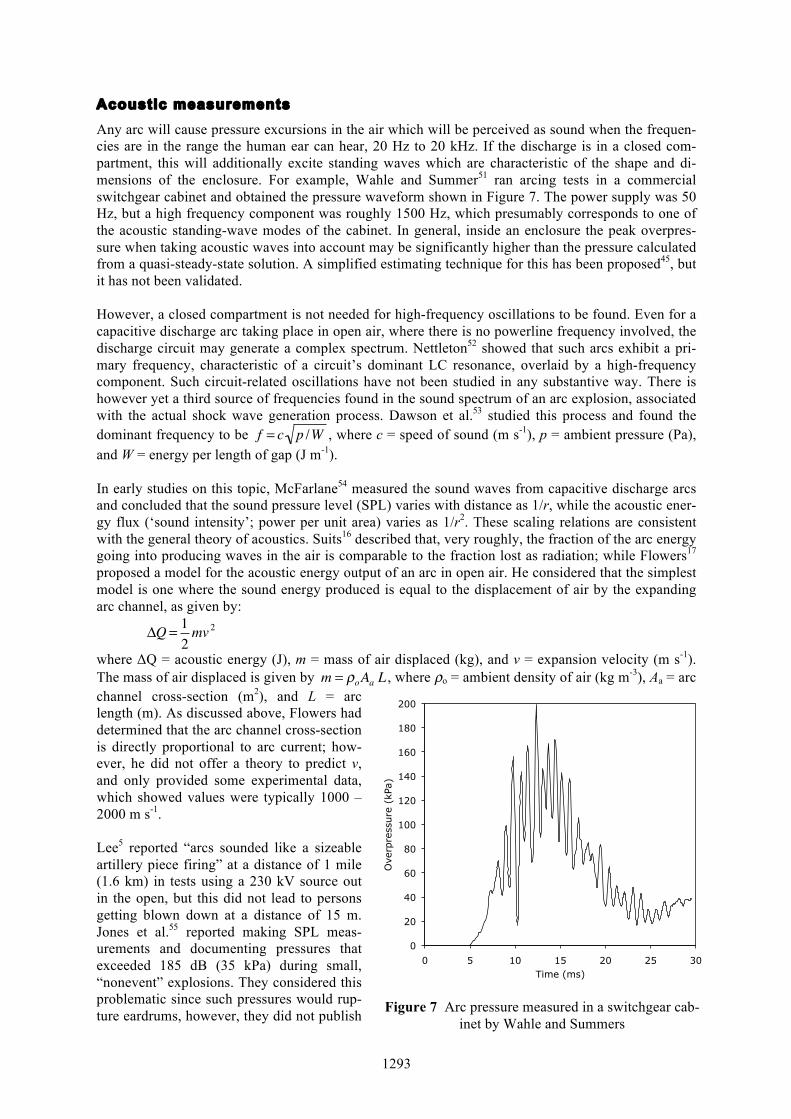
Acoustic measurements Any arc will cause pressure excursions in the air which will be perceived as sound when the frequen-cies are in the range the human ear can hear, 20 Hz to 20 kHz. If the discharge is in a closed com-partment, this will additionally excite standing waves which are characteristic of the shape and di-mensions of the enclosure. For example, Wahle and Summer51 ran arcing tests in a commercial switchgear cabinet and obtained the pressure waveform shown in Figure 7. The power supply was 50 Hz, but a high frequency component was roughly 1500 Hz, which presumably corresponds to one of the acoustic standing-wave modes of the cabinet. In general, inside an enclosure the peak overpres-sure when taking acoustic waves into account may be significantly higher than the pressure calculated from a quasi-steady-state solution. A simplified estimating technique for this has been proposed45, but it has not been validated. However, a closed compartment is not needed for high-frequency oscillations to be found. Even for a capacitive discharge arc taking place in open air, where there is no powerline frequency involved, the discharge circuit may generate a complex spectrum. Nettleton52 showed that such arcs exhibit a pri-mary frequency, characteristic of a circuit’s dominant LC resonance, overlaid by a high-frequency component. Such circuit-related oscillations have not been studied in any substantive way. There is however yet a third source of frequencies found in the sound spectrum of an arc explosion, associated with the actual shock wave generation process. Dawson et al.53 studied this process and found the dominant frequency to be
�
f = c p /W , where c = speed of sound (m s-1), p = ambient pressure (Pa), and W = energy per length of gap (J m-1). In early studies on this topic, McFarlane54 measured the sound waves from capacitive discharge arcs and concluded that the sound pressure level (SPL) varies with distance as 1/r, while the acoustic ener-gy flux (‘sound intensity’; power per unit area) varies as 1/r2. These scaling relations are consistent with the general theory of acoustics. Suits16 described that, very roughly, the fraction of the arc energy going into producing waves in the air is comparable to the fraction lost as radiation; while Flowers17 proposed a model for the acoustic energy output of an arc in open air. He considered that the simplest model is one where the sound energy produced is equal to the displacement of air by the expanding arc channel, as given by:
�
ΔQ = 12mv 2
where ΔQ = acoustic energy (J), m = mass of air displaced (kg), and v = expansion velocity (m s-1). The mass of air displaced is given by
�
m = ρoAa L , where ρo = ambient density of air (kg m-3), Aa = arc channel cross-section (m2), and L = arc length (m). As discussed above, Flowers had determined that the arc channel cross-section is directly proportional to arc current; how-ever, he did not offer a theory to predict v, and only provided some experimental data, which showed values were typically 1000 – 2000 m s-1. Lee5 reported “arcs sounded like a sizeable artillery piece firing” at a distance of 1 mile (1.6 km) in tests using a 230 kV source out in the open, but this did not lead to persons getting blown down at a distance of 15 m. Jones et al.55 reported making SPL meas-urements and documenting pressures that exceeded 185 dB (35 kPa) during small, “nonevent” explosions. They considered this problematic since such pressures would rup-ture eardrums, however, they did not publish
0
20
40
60
80
100
120
140
160
180
200
0 5 10 15 20 25 30
Ove
rpre
ssure
(kP
a)
Time (ms)
Figure 7 Arc pressure measured in a switchgear cab-inet by Wahle and Summers

1294
details of their work. Doughty et al.56 measured 3-phase arc explosions where the arc currents ranged up to 29 kA; they recorded a peak SPL of 163 dB (2.8 kPa). In general, it can be concluded that acoustic phenomena have been studied only to a limited extent, SPL measurements of arc explosions are rare, and available guidance is scant.
Summary and conclusions When an arc breakdown is initiated, energy gets deposited into the arc channel at a rate much greater than can be removed from the area by the shock wave that is created. This causes a rapid pressure rise and, if the arc energy is sufficiently high, this will be perceived as an explosion. For a low-energy arc, the perceived sound may simple be a ‘snap,’ ‘crackle,’ or ‘pop.’ But within the scientific community there is not an agreed-upon, quantitative definition12 of the term ‘explosion,’ nor are there studies to quantify the fraction of the arc energy that gets delivered as sound energy, i.e., vibrations in the 20 Hz – 20 kHz range. Electric arc explosions are not combustion phenomena—they are predominantly physical explosions, due to very rapid conversion of electrical energy into heat. Chemical reactions play a role, but only a supporting role, in such explosions. Recent studies suggest that chemical reactions are mainly ones which convert air to species such as O3 and NOx. While these may comprise oxidation, they are very different from a fuel-air explosion of a normal sort. Some of the electrode metal is also vaporized in an arc explosion, and arc temperatures are high enough so that presumably much of this metal vapor may get oxidized. However, the electrode oxidation effect is quantitatively only a small part of the heat balance in an arc explosion. Thus, first-order estimates of arc explosions treat the process solely as converting electrical energy to heat and ignore chemical reaction contributions. In an open environment, arc pressures will rarely be highly destructive. Theoretical modeling suggests that very high pressures may be created, but experimental studies do not bear this out. Using a 4 MV discharge, Uman did not measure any overpressures above 10 kPa, while Drouet and Nadeau’s work indicates that at 0.3 m from an 480 Vrms, 80 kArms arc, an overpressure of only 8.7 kPa will result. But on the other hand, if a high fault current is available and arcing takes place in a small enclosure, ex-tremely high overpressures can be reached, measured in one case at 409 atm. Arc flash, which is not considered in this paper, comprises the main injury potential in open arcing, instead of high pressures. For arcing in small enclosures, the initial hazard may be destruction of equipment. But serious injuries may occur as consequential damages, e.g., trauma to persons from airborne cabinet parts. In addition, arcing may continue after a cabinet failure and injuries from arc flash may then ensue. Most accidents involve AC power. However, for arcing within small enclosures, DC arcs are more hazardous than capacitive discharge or AC arcs. With DC arcs, arcing can continue for a long time, and during this time the enclosure pressure will progressively rise. With capacitive discharge arcs, the event is intrinsically short-lived. With AC arcs, continued re-ignitions of the arc may take place, nonetheless peak overpressures will tend to be much lower than for DC conditions. A direct, quantita-tive comparison between DC and AC arcs is not possible, however, since AC arcs do not have a unique waveform and will depend on circuit characteristics. While many accidents involving AC arcs take place where voltages are 480 VAC, or higher, destructive arcing can also occur with 120 – 240 VAC sources, provided sufficient current capacity, e.g., kiloamps, is available. Very little test or modeling data exist on arcing in closed, unvented, unruptured enclosures. This would be especially germane to arcs where the power source is sustained, i.e., DC or AC arcs, as op-posed to capacitive discharges. These conditions may not necessarily represent a direct injury poten-tial, but the analysis is simpler and reliable data would useful for validating of theories. Apart from some very early studies, there has not been significant experimental work on DC arcs. A number of industries use DC and studies specific to DC power supplies would be valuable. In line with other fields of engineering, in recent years it has become common to conduct research studies based on CFD modeling. Unfortunately such studies only rarely lead to phenomenological

1295
insights or conclusions having general applicability. In addition, unless accompanied by a careful and successful validation, the numerical results may be in serious error.
References 1. Short, T. A., Arc Flash Analysis Approaches for Medium-Voltage Distribution, Rural Electric Power Conf.
(REPC '09), IEEE (2009). 2. Lindmayer, M., and Paulke, J., Arc Motion and Pressure Formation in Low Voltage Switchgear, IEEE
Trans. on Components, Packaging, and Manufacturing Technology A21, 33-39 (1998). 3. Nabours, Robert E., Fish, R. M., and Hill, P. F., Electrical Injuries: Engineering, Medical and Legal
Aspects, 2nd ed., Lawyers & Judges Publishing Co. (2004). 4. Mazer, W. M., Electrical Accident Investigation Handbook, 3 vols., Electrodata, Inc., Glen Echo MD
(var. dates). 5. Lee, R. H., Pressures Developed by Arcs, IEEE Trans. on Industry Applications IA-23, 760-764 (1987). 6. Crawford, K. S., Clark, D. G., and Doughty, R. L., Motor Terminal Box Explosions due to Faults, IEEE
Trans. on Industry Applications 29, 257-267 (1993). 7. Heberlein, G. E. jr., Higgins, J. A., and Epperly, R.A., Report on Enclosure Internal Arcing Tests, IEEE
Industry Applications Magazine 2:3, 35-42 (May/June 1996). 8. Jennings, C., Fire-Fatality High-Rise Office Building Fire, Atlanta, Georgia (June 30, 1989), US Fire Ad-
min., [Emmitsburg MD], (1989). 9. Graneau, P., The Cause of Thunder, J. Physics D: Applied Physics 22, 1083-1094 (1989). 10. Lee, R. H., The Shattering Effect of Lightning—Pressure from Heating of Air by Stroke Current, IEEE
Transactions on Industry Applications 22, 416-419 (1986). 11. Eisenberg, N. A., Lynch, C. J., and Breeding, R. J., Vulnerability Model: Assessing Damage from Maritime
Spills by Computer Simulation (CG-D-136-75), US Coast Guard, Washington (1975). 12. Babrauskas, V., Ignition Handbook, Fire Science Publishers/Society of Fire Protection Engineers, Is-
saquah WA (2003). 13. Graneau, P., Graneau, N., and Hathaway, G., Evidence of Thunder Being a Chemical Explosion of Air, J.
Plasma Physics 69 part 3, 187-197 (2003). 14. Baker, W. E. et al., Explosion Hazards and Evaluation, Elsevier, Amsterdam (1983). 15. Baker, W. E., and Tang, M. J., Gas, Dust and Hybrid Explosions, Elsevier, Amsterdam (1991). 16. Suits, C. G., Notes on High-intensity Sound Waves, General Electric Review 39, 430-434 (1936). 17. Flowers, J. W., The Channel of the Spark Discharge, Physical Review 64:7/8, 225-235 (1943). 18. Vanyukov, M. P., Isaenko, V. I., and Khazov, L. D., Investigation of Light Phenomena Related to the De-
velopment of the Spark-Discharge Channel, Zhurnal tekhnicheskoĭ fiziki 25, 1248 (1955). 19. Higham, J. B., and Meek, J. M., The Expansion of Gaseous Spark Channels, Proc. Physical Society B 63,
649-661 (1950). 20. Drabkina, S. I., Theory of the Development of a Spark Discharge Channel, Zhurnal ėksperimentalʹnoĭ i
teoreticheskoĭ fiziki 21:4, 473-493 (1951). 21. Hill, R. D., Channel Heating in Return-Stroke Lightning, J. Geophysics Research 76, 637-645 (1971). 22. Freeman, R. A., and Craggs, J. D., Shock Waves from Spark Discharges, British J. Applied Physics (J.
Physics D), series 2, 2, 421-427 (1969). 23. Uman, M. A., Cookson, A. H., and Moreland, J. B., Shock Wave from a Four-Meter Spark, J. Applied
Physics 41, 3148-3155 (1970). 24. Plooster, M. N., Shock Waves from Line Sources: Numerical Solutions and Experimental Measurements,
Physics of Fluids 13, 2665-2675 (1970). 25. Brode, H. L., Blast Wave from Spherical Charges, Physics of Fluids 2, 217-229 (1959). 26. Drouet, M. G., and Nadeau, F., Pressure Waves due to Arcing Faults in a Substation, IEEE Trans. on Pow-
er Apparatus and. Systems PAS-98, 1632-1635 (1979). 27. Thorén, B., Ljusbågar på kraftlinjer och i högspänningsställverk [Arcs on Power Lines and in High Voltage
Switchgear], Elteknik 5, 139-143 (1962). 28. Dasbach, A., and Pietsch, G., Investigation of the Power Balance of High Current Faults, pp. 15-18 in Proc.
9th Intl. Conf. on Gas Discharges and Their Applications (GD88), Venice (1988). 29. Baldrey, H. W., and Hudson, A. A., Pressures Generated by Fault Arcs in Small Enclosures (Ref. Z/T134),
The British Electrical and Allied Industries Research Assn., Leatherhead, Surrey, England (1961). 30. Allsop, G., and Wheeler, R. V., The Pressures Produced on Blowing Electric Fuse Links (Paper No. 38),
Safety in Mines Research Board, [n.p.] (1927). 31. Allsop, G., and Wheeler, R. V., The Pressures Produced by Electric Arcs in Closed Vessels (Paper No. 39,
Safety in Mines Research Board, [n.p.] (1927).

1296
32. Allsop, G., The Pressure Produced on Blowing Electric Fuse Links and Striking Electric Arcs in Closed
Vessels (Paper No. 52), Safety in Mines Research Board, [n.p.] (1929). 33. Allsop, G., and Smith, P. B., The Pressures Produced on Blowing Electric Fuse Links: The Effect of the
Surrounding Atmosphere (Paper No. 67), Safety in Mines Research Board, [n.p.] (1931). 34. Hennecke, G., and Horn, W., About Development and Radiation Pressure in Arcing Short Circuits in Sub-
stations, Conti Elektro Berichte 6:3, 119-128 (July/Sept. 1960). 35. Friberg, G., Pietsch, G., and Schumacher, M., On the Description of Pressure Rise in the Surroundings of
High Current Arcs in Metal-Enclosed Compartments with Pressure Relief, pp. I-18 to I-21 in Proc. 11th Intl. Conf. on Gas Discharges and Their Applications (GD95), Chuo University, Tokyo (1995).
36. Teera-achariyakul, N., and Hokierti, J., Internal Arc Pressure Assessment of Outdoor Compact Substation, IPEC 2005: 7th Intl. Power Engineering Conf., IEEE, New York (2005).
37. Cobine, J. D., and Burger, E. E., Analysis of Electrode Phenomena in the High-Current Arc, J. Applied Physics 26, 895-900 (1955).
38. Binnendijk, M., Schoonenberg, G. C., and Lammers, A. J. W., The Prevention and Control of Internal Arcs in Medium-Voltage Switchgear, CIRED - 14th Intl. Conf. and Exhibition on Electricity Distribution (IEE Conf. Publ. No. 438), IEE, Rugby, England (1997).
39. Lutz, F., and Pietsch, G., The Calculation of Overpressure in Metal-Enclosed Switchgear due to Internal Arcing, IEEE Trans. on Power Apparatus & Systems PAS101, 4230-4236 (1982).
40. Iwata, M., Anantavanich, K., and Pietsch, G. J., Influence of Arc Current on Fraction Kp of Electric Arc Energy Leading to Pressure Rise in a Closed Container, pp. 189-192 in Proc. 17th Intl. Conf. on Gas Dis-charges and Their Applications, Cardiff, UK (2008).
41. Rahal, A. M., et al., Pressure Transients in a Self-Blown Circuit Breaker, pp. 95-98 in Proc. 8th Intl. Conf. on Gas Discharges and Their Applications (GD85), Leeds Univ. Press, Leeds (1985).
42. Zhang, X., Zhang., J., and Pietsch, G., Estimation of the Arc Power During a Three-Phase Arc Fault in MV Electrical Installations, IEEE Transactions on Plasma Science 35, 724-730 (2007).
43. Zhang, X., Pietsch, G., and Gockenbach, E., Investigation of the Thermal Transfer Coefficient by the Ener-gy Balance of Fault Arcs in Electrical Installations, IEEE Trans. on Power Delivery 21, 425-431 (2006).
44. Friberg, G., and Pietsch, G. J., Calculation of Pressure Rise due to Arcing Faults, IEEE Trans. on Power Delivery 14, 365-370 (1999).
45. Dasbach, A., and Pietsch, G. J., The Calculation of Pressure Waves in Substation Buildings due to Arcing Faults, IEEE Trans. Power Delivery 5, 1760-1765 (1990).
46. Capelli-Schellpfeffer, M.,, Miller, G. H., and Humilier, M., Thermoacoustic Energy Effects in Electrical Arcs, pp. 19-32 in Occupational Electrical Injury: An Intl. Symp., / Annals of the New York Academy of Sciences, Vol. 888, New York Academy of Sciences, New York (1999).
47. Bowen, J. E., Wactor, M. W., Miller, G. H., and Capelli-Schellpfeffer, M., Catch the Wave: Modeling the Pressure Wave Associated with Arc Fault, IEEE Industry Applications Magazine 10:4, 59-67 (Aug. 2004).
48. Caillard, J., de Izarra C., Brunet, L, Vallée, O., and Gillard, P., Assessment of the Blast Wave Generated by a Low-Energy Plasma Igniter and Spectroscopic Measurements, IEEE Trans. on Magnetics 39, 212-217 (2003).
49. Even, A., et al., Design of Distribution Cabins to Withstand Internal Arcing, CIRED - 16th Intl. Conf. and Exhibition on Electricity Distribution (IEE Conf. Publ No. 482), IEE, Rugby, England (2001).
50. Schmale, M., and Pietsch, G. J., Influence of Buffer Volumes on Pressure Rise in Switchgear Installations due to Internal Arcing, pp. 201-204 in Proc. 17th Intl. Conf. on Gas Discharges and their Applications, Cardiff, UK (2008).
51. Wahle, A. B., and Summer, R. F., Internal Arc Testing of Medium Voltage Switchgear—Experiences with IEC 62271-200, CIRED 2007 – 19th Intl. Conf. on Electricity Distribution (2007).
52. Nettleton, M. A., discussion to paper of Drouet and Nadeau, op cit. 53. Dawson, G. A., Richards, C. N., Krider, E. P., and Uman, M. A., The Acoustic Output of a Long Spark, J.
Geophysical Research 73, 815-816 (1968). 54. McFarlane, W., The Sound Radiation from a Condenser Discharge, Philosophical Magazine 18:117, 24-36
(1934). 55. Jones, R. A., et al., Staged Tests Increase Awareness of Arc-Flash Hazards in Electrical Equipment, IEEE
Trans. on Industry Applications 36, 659-667 (2000). 56. Doughty, R. L., Neal, T. E., Dear, T. A., and Bingham, A. H., Testing Update on Protective Clothing and
Equipment for Electric Arc Exposure, IEEE Industry Applications Magazine 5:1, 37-49 (Jan./Feb. 1999).
Related Documents