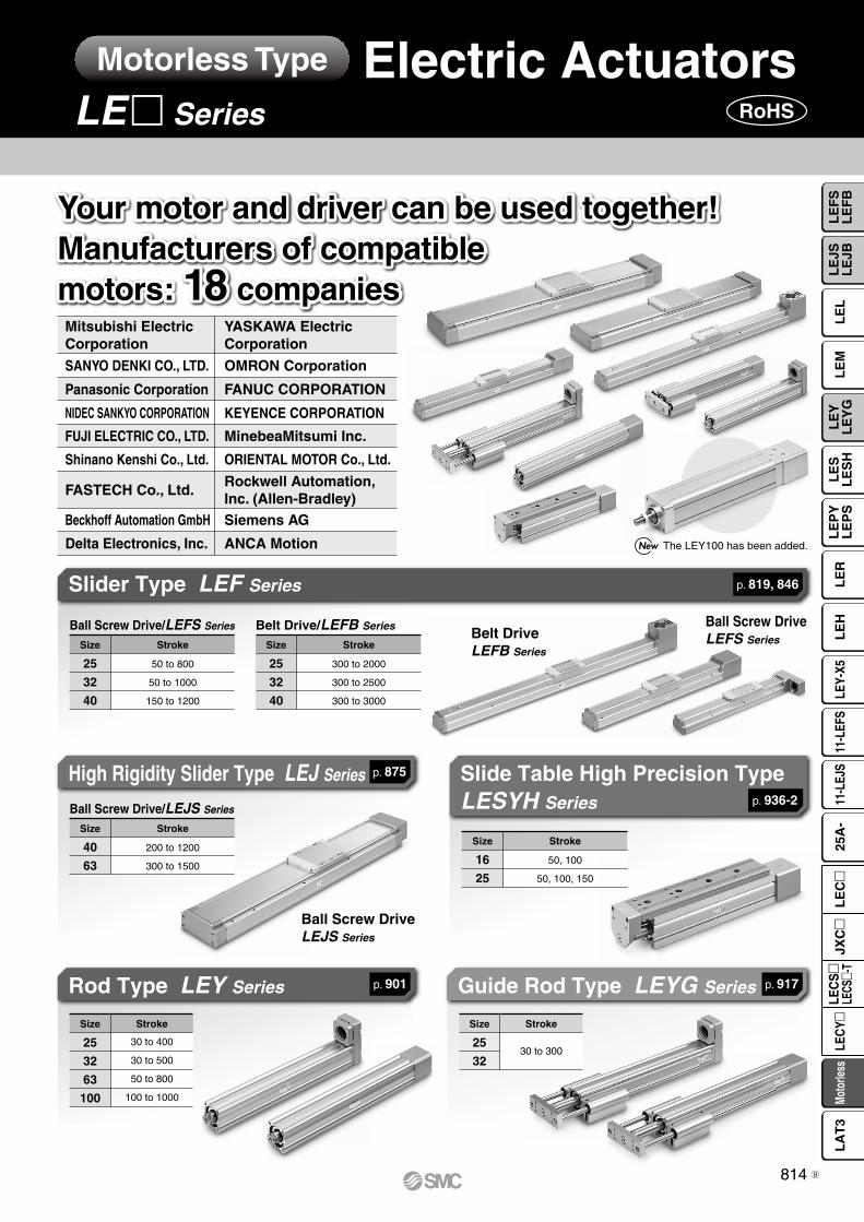
SANYO DENKI CO., LTD. Panasonic Corporation NIDEC SANKYO CORPORATION Mitsubishi Electric Corporation OMRON Corporation FANUC CORPORATION KEYENCE CORPORATION YASKAWA Electric Corporation Rockwell Automation, Inc. (Allen-Bradley) Beckhoff Automation GmbH Siemens AG FUJI ELECTRIC CO., LTD. MinebeaMitsumi Inc. Shinano Kenshi Co., Ltd. ORIENTAL MOTOR Co., Ltd. FASTECH Co., Ltd. Delta Electronics, Inc. ANCA Motion Your motor and driver can be used together! Manufacturers of compatible motors: 18 companies Your motor and driver can be used together! Manufacturers of compatible motors: 18 companies Belt Drive LEFB Series Ball Screw Drive LEFS Series Ball Screw Drive LEJS Series Slider Type LEF Series High Rigidity Slider Type LEJ Series Rod Type LEY Series Guide Rod Type LEYG Series Ball Screw Drive/LEFS Series Stroke 50 to 800 50 to 1000 150 to 1200 Size 25 32 40 Belt Drive/LEFB Series Stroke 300 to 2000 300 to 2500 300 to 3000 Size 25 32 40 Ball Screw Drive/LEJS Series Stroke 200 to 1200 300 to 1500 Size 40 63 Stroke 30 to 400 30 to 500 50 to 800 100 to 1000 Size 25 32 63 100 Stroke 30 to 300 Size 25 32 p. 819, 846 p. 875 p. 901 p. 917 Slide Table High Precision Type LESYH Series Stroke 50, 100 50, 100, 150 Size 16 25 p. 936-2 The LEY100 has been added. Electric Actuators LE m Series RoHS Motorless Type 814 LEFS LEFB LEL LEJS LEJB LEM LEY LEYG LES LESH LEPY LEPS LER LEH LEY-X5 11-LEFS 11-LEJS 25A- Motorless LECY LECS LECS-T JXC LEC LAT3 B

Welcome message from author
This document is posted to help you gain knowledge. Please leave a comment to let me know what you think about it! Share it to your friends and learn new things together.
Transcript
SANYO DENKI CO., LTD.
Panasonic Corporation
NIDEC SANKYO CORPORATION
Mitsubishi Electric Corporation
OMRON Corporation
FANUC CORPORATION
KEYENCE CORPORATION
YASKAWA Electric Corporation
Rockwell Automation,Inc. (Allen-Bradley)
Beckhoff Automation GmbH Siemens AG
FUJI ELECTRIC CO., LTD. MinebeaMitsumi Inc.
Shinano Kenshi Co., Ltd. ORIENTAL MOTOR Co., Ltd.
FASTECH Co., Ltd.
Delta Electronics, Inc. ANCA Motion
Your motor and driver can be used together!Manufacturers of compatiblemotors: 18 companies
Your motor and driver can be used together!Manufacturers of compatiblemotors: 18 companies
Belt DriveLEFB Series
Ball Screw DriveLEFS Series
Ball Screw DriveLEJS Series
Slider Type LEF Series
High Rigidity Slider Type LEJ Series
Rod Type LEY Series Guide Rod Type LEYG Series
Ball Screw Drive/LEFS Series
Stroke
50 to 800
50 to 1000
150 to 1200
Size
25
32
40
Belt Drive/LEFB Series
Stroke
300 to 2000
300 to 2500
300 to 3000
Size
25
32
40
Ball Screw Drive/LEJS Series
Stroke
200 to 1200
300 to 1500
Size
40
63
Stroke
30 to 400
30 to 500
50 to 800
100 to 1000
Size
25
32
63
100
Stroke
30 to 300
Size
25
32
p. 819, 846
p. 875
p. 901 p. 917
Slide Table High Precision TypeLESYH Series
Stroke
50, 100
50, 100, 150
Size
16
25
p. 936-2
The LEY100 has been added.
Electric ActuatorsLEm Series RoHS
Motorless Type
814
LE
FS
LE
FB
LE
LL
EJS
LE
JBL
EM
LE
YL
EY
GL
ES
LE
SH
LE
PY
LE
PS
LE
RL
EH
LEY-
X511
-LEF
S11
-LEJ
S25
A-
Moto
rless
LEC
Y�LE
CS
�LE
CS�-
TJX
C�
LE
C�
LA
T3
B
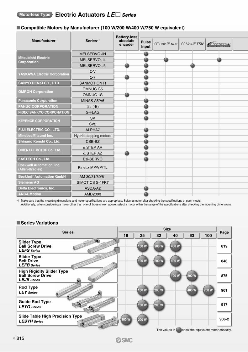
�Compatible Motors by Manufacturer (100 W/200 W/400 W/750 W equivalent)
∗1 Make sure that the mounting dimensions and motor specifications are appropriate. Select a motor after checking the specifications of each model.Additionally, when considering a motor other than one of those shown above, select a motor within the range of the specifications after checking the mounting dimensions.
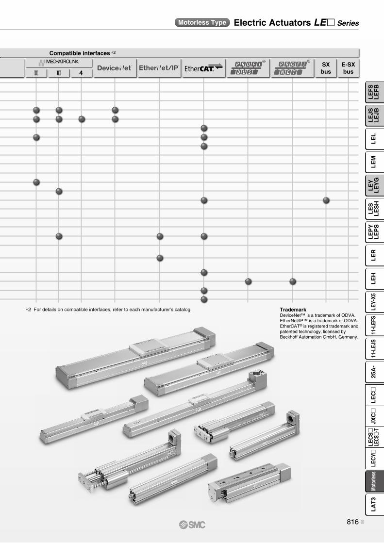
∗2 For details on compatible interfaces, refer to each manufacturer’s catalog.
�Series Variations
Electric Actuators LE� SeriesMotorless Type Electric Actuators LE� SeriesMotorless Type
Series
Slider TypeBall Screw DriveLEFS Series
Slider TypeBelt DriveLEFB Series
High Rigidity Slider TypeBall Screw DriveLEJS Series
Rod TypeLEY Series
Guide Rod TypeLEYG Series
Slide Table High Precision TypeLESYH Series
Size
2516 32 40 63 100
819
846
875
901
917
936-2
Page
Manufacturer Series∗1
Compatible interfaces ∗2
Pulseinput
Battery-lessabsoluteencoder
@ # 4SXbus
E-SXbus
TrademarkDeviceNet™ is a trademark of ODVA.EtherNet/IP™ is a trademark of ODVA.EtherCAT® is registered trademark and patented technology, licensed by Beckhoff Automation GmbH, Germany.
The values in show the equivalent motor capacity.
100 W 200 W 400 W
100 W 200 W 400 W
100 W 200 W
100 W 200 W 400 W 750 W
100 W
200 W100 W
200 W
MELSERVO JN
MELSERVO J4
MELSERVO J5
Σ-V
Σ-7
SANMOTION R
OMNUC G5
OMNUC 1S
MINAS A5/A6
βis (-B)
S-FLAG
SV
SV2
ALPHA7
Hybrid stepping motors
CSB-BZ
α STEP AR
α STEP AZ
Ezi-SERVO
Kinetix MP/VP/TL
AM 30/31/80/81
SIMOTICS S-1FK7
ASDA-A2
AMD2000
Rockwell Automation, Inc.(Allen-Bradley)
Beckhoff Automation GmbH
Siemens AG
Delta Electronics, Inc.
ANCA Motion
Mitsubishi ElectricCorporation
YASKAWA Electric Corporation
SANYO DENKI CO., LTD.
OMRON Corporation
KEYENCE CORPORATION
ORIENTAL MOTOR Co., Ltd.
FASTECH Co., Ltd.
FUJI ELECTRIC CO., LTD.
MinebeaMitsumi Inc.
Shinano Kenshi Co., Ltd.
Panasonic Corporation
FANUC CORPORATION
NIDEC SANKYO CORPORATION
815C
�Compatible Motors by Manufacturer (100 W/200 W/400 W/750 W equivalent)
∗1 Make sure that the mounting dimensions and motor specifications are appropriate. Select a motor after checking the specifications of each model.Additionally, when considering a motor other than one of those shown above, select a motor within the range of the specifications after checking the mounting dimensions.
∗2 For details on compatible interfaces, refer to each manufacturer’s catalog.
�Series Variations
Electric Actuators LE� SeriesMotorless Type Electric Actuators LE� SeriesMotorless Type
Series
Slider TypeBall Screw DriveLEFS Series
Slider TypeBelt DriveLEFB Series
High Rigidity Slider TypeBall Screw DriveLEJS Series
Rod TypeLEY Series
Guide Rod TypeLEYG Series
Slide Table High Precision TypeLESYH Series
Size
2516 32 40 63 100
819
846
875
901
917
936-2
Page
Manufacturer Series∗1
Compatible interfaces ∗2
Pulseinput
Battery-lessabsoluteencoder
@ # 4SXbus
E-SXbus
TrademarkDeviceNet™ is a trademark of ODVA.EtherNet/IP™ is a trademark of ODVA.EtherCAT® is registered trademark and patented technology, licensed by Beckhoff Automation GmbH, Germany.
The values in show the equivalent motor capacity.
100 W 200 W 400 W
100 W 200 W 400 W
100 W 200 W
100 W 200 W 400 W 750 W
100 W
200 W100 W
200 W
MELSERVO JN
MELSERVO J4
MELSERVO J5
Σ-V
Σ-7
SANMOTION R
OMNUC G5
OMNUC 1S
MINAS A5/A6
βis (-B)
S-FLAG
SV
SV2
ALPHA7
Hybrid stepping motors
CSB-BZ
α STEP AR
α STEP AZ
Ezi-SERVO
Kinetix MP/VP/TL
AM 30/31/80/81
SIMOTICS S-1FK7
ASDA-A2
AMD2000
Rockwell Automation, Inc.(Allen-Bradley)
Beckhoff Automation GmbH
Siemens AG
Delta Electronics, Inc.
ANCA Motion
Mitsubishi ElectricCorporation
YASKAWA Electric Corporation
SANYO DENKI CO., LTD.
OMRON Corporation
KEYENCE CORPORATION
ORIENTAL MOTOR Co., Ltd.
FASTECH Co., Ltd.
FUJI ELECTRIC CO., LTD.
MinebeaMitsumi Inc.
Shinano Kenshi Co., Ltd.
Panasonic Corporation
FANUC CORPORATION
NIDEC SANKYO CORPORATION
816
LE
FS
LE
FB
LE
LL
EJS
LE
JBL
EM
LE
YL
EY
GL
ES
LE
SH
LE
PY
LE
PS
LE
RL
EH
LEY-
X511
-LEF
S11
-LEJ
S25
A-
Moto
rless
LEC
Y�LE
CS
�LE
CS�-
TJX
C�
LE
C�
LA
T3
B
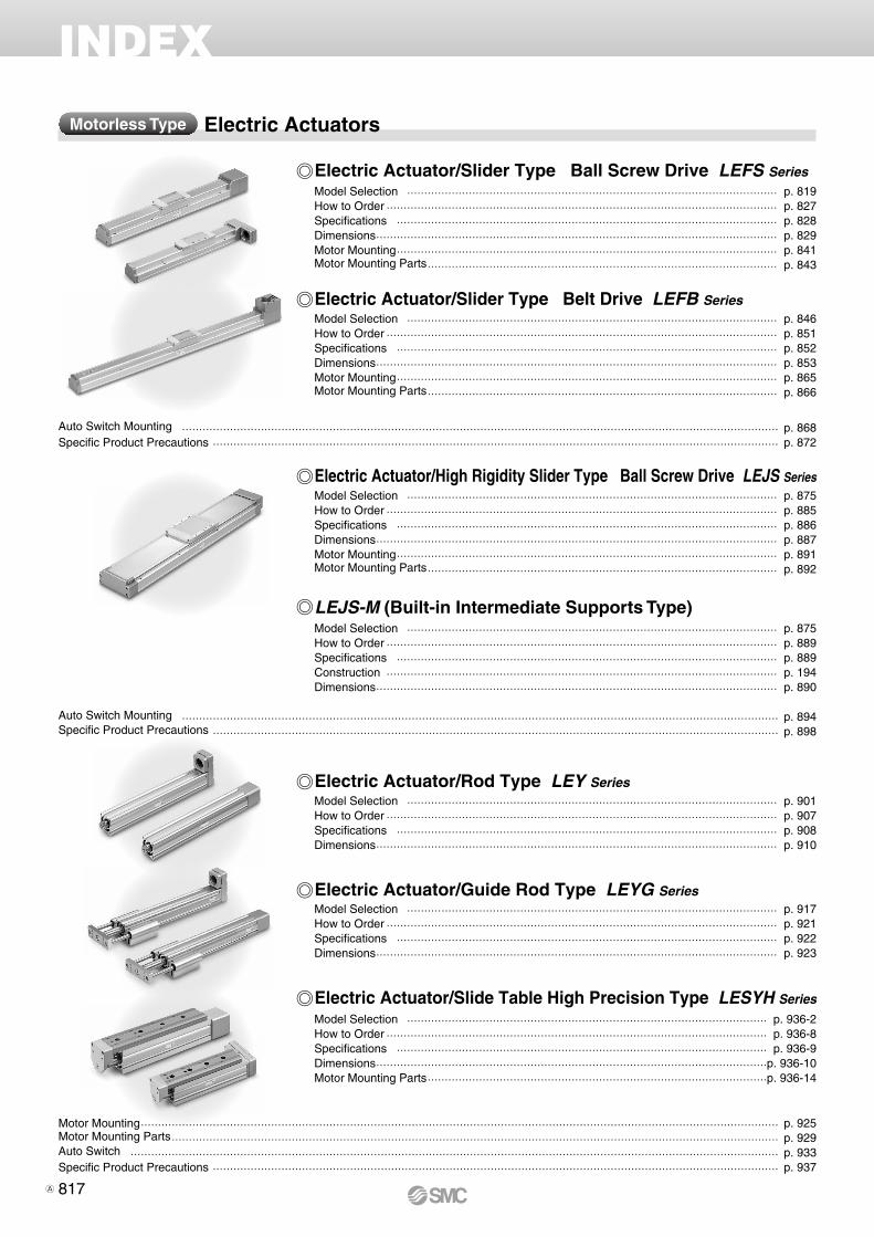
INDEX
Electric ActuatorsMotorless Type
Electric Actuator/Slider Type Ball Screw Drive LEFS SeriesModel Selection ������������������������������������ p. 819How to Order �������������������������������������� p. 827Specifications ������������������������������������� p. 828Dimensions ��������������������������������������� p. 829Motor Mounting ������������������������������������� p. 841Motor Mounting Parts ���������������������������������� p. 843
Electric Actuator/Rod Type LEY SeriesModel Selection ������������������������������������ p. 901How to Order �������������������������������������� p. 907Specifications ������������������������������������� p. 908Dimensions ��������������������������������������� p. 910
Electric Actuator/High Rigidity Slider Type Ball Screw Drive LEJS SeriesModel Selection ������������������������������������ p. 875How to Order �������������������������������������� p. 885Specifications ������������������������������������� p. 886Dimensions ��������������������������������������� p. 887Motor Mounting ������������������������������������� p. 891Motor Mounting Parts ���������������������������������� p. 892
Electric Actuator/Guide Rod Type LEYG SeriesModel Selection ������������������������������������ p. 917How to Order �������������������������������������� p. 921Specifications ������������������������������������� p. 922Dimensions ��������������������������������������� p. 923
Electric Actuator/Slider Type Belt Drive LEFB SeriesModel Selection ������������������������������������ p. 846How to Order �������������������������������������� p. 851Specifications ������������������������������������� p. 852Dimensions ��������������������������������������� p. 853Motor Mounting ������������������������������������� p. 865Motor Mounting Parts ���������������������������������� p. 866
LEJS-M (Built-in Intermediate Supports Type)Model Selection ������������������������������������ p. 875How to Order �������������������������������������� p. 889Specifications ������������������������������������� p. 889Construction �������������������������������������� p. 194Dimensions ��������������������������������������� p. 890
Auto Switch Mounting ���������������������������������������������������������� p. 894Specific Product Precautions ������������������������������������������������������� p. 898
Motor Mounting �������������������������������������������������������������� p. 925Motor Mounting Parts ����������������������������������������������������������� p. 929Auto Switch ��������������������������������������������������������������� p. 933Specific Product Precautions ������������������������������������������������������� p. 937
Auto Switch Mounting ���������������������������������������������������������� p. 868Specific Product Precautions ������������������������������������������������������� p. 872
Electric Actuator/Slide Table High Precision Type LESYH SeriesModel Selection ����������������������������������� p. 936-2How to Order ������������������������������������� p. 936-8Specifications ������������������������������������ p. 936-9Dimensions ��������������������������������������p. 936-10Motor Mounting Parts ���������������������������������p. 936-14
817A
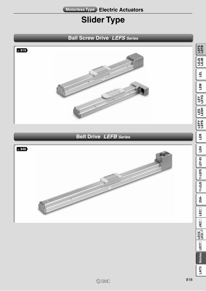
Slider TypeMotorless Type Electric Actuators
Ball Screw Drive LEFS Series
Belt Drive LEFB Series
p. 846
p. 819
818
LE
FS
LE
FB
LE
LL
EJS
LE
JBL
EM
LE
YL
EY
GL
ES
LE
SH
LE
PY
LE
PS
LE
RL
EH
LEY-
X511
-LEF
S11
-LEJ
S25
A-
Moto
rless
LEC
Y�LE
CS
�LE
CS�-
TJX
C�
LE
C�
LA
T3
Work load [kg]
Ove
rhan
g: L
3 [m
m] 1000 mm/s2
3000 mm/s2
5000 mm/s2
0 10 20 30 40 50 60
1500
1000
500
0
L3
Mep
m
100
W
0
10
20
30
40
50
60
70
0 200 400 600 800 1000 1200 1400 1600
Wor
k lo
ad: W
[kg]
Speed: V [mm/s]
Lead 20: LEFS�40�A
Lead 10: LEFS�40�B
Lead 30: LEFS�40�H
T1
a1 a2
L
Spe
ed: V
[mm
/s]
Time[s]
T2 T3 T4
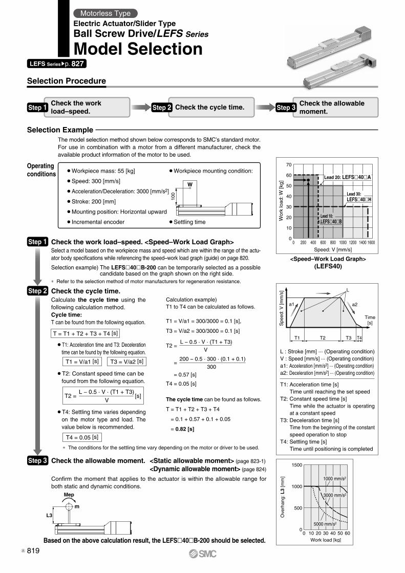
Selection Procedure
<Speed–Work Load Graph>(LEFS40)
L : Stroke [mm] ··· (Operating condition)V : Speed [mm/s] ··· (Operating condition)a1: Acceleration [mm/s2] ··· (Operating condition)a2: Deceleration [mm/s2] ··· (Operating condition)
T1: Acceleration time [s]Time until reaching the set speed
T2: Constant speed time [s]Time while the actuator is operating at a constant speed
T3: Deceleration time [s]Time from the beginning of the constant speed operation to stop
T4: Settling time [s]Time until positioning is completed
¡Workpiece mass: 55 [kg]
¡Speed: 300 [mm/s]
¡Acceleration/Deceleration: 3000 [mm/s2]
¡Stroke: 200 [mm]
¡Mounting position: Horizontal upward
¡Incremental encoder
¡Workpiece mounting condition:
¡Settling time
Check the work load–speed. <Speed–Work Load Graph>Select a model based on the workpiece mass and speed which are within the range of the actu-ator body specifications while referencing the speed–work load graph (guide) on page 820.
Selection example) The LEFSl40lB-200 can be temporarily selected as a possible candidate based on the graph shown on the right side.
Check the cycle time.Calculate the cycle time using the following calculation method.Cycle time: T can be found from the following equation.
¡T4: Settling time varies depending on the motor type and load. The value below is recommended.
¡T2: Constant speed time can befound from the following equation.
¡T1: Acceleration time and T3: Deceleration time can be found by the following equation.
Calculation example)T1 to T4 can be calculated as follows.
T1 = V/a1 = 300/3000 = 0.1 [s],
T3 = V/a2 = 300/3000 = 0.1 [s]
T4 = 0.05 [s]
The cycle time can be found as follows.
T = T1 + T2 + T3 + T4
= 0.1 + 0.57 + 0.1 + 0.05
= 0.82 [s]
T2 =
=
= 0.57 [s]
* The conditions for the settling time vary depending on the motor or driver to be used.
Selection Example
Operating conditions
T = T1 + T2 + T3 + T4 [s]
T4 = 0.05 [s]
T1 = V/a1 [s] T3 = V/a2 [s]
T2 = [s]L − 0.5 · V · (T1 + T3)
V
Step 1
Step 2
Step 3
Based on the above calculation result, the LEFSl40lB-200 should be selected.
L − 0.5 · V · (T1 + T3)
V
200 − 0.5 · 300 · (0.1 + 0.1)
300
Step 1 Check the work load–speed. Step 2 Check the cycle time. Step 3 Check the allowable
moment.
* Refer to the selection method of motor manufacturers for regeneration resistance.
LEFS Seriessp. 827
Motorless TypeElectric Actuator/Slider TypeBall Screw Drive/LEFS Series
Model Selection
The model selection method shown below corresponds to SMC’s standard motor.For use in combination with a motor from a different manufacturer, check the available product information of the motor to be used.
Check the allowable moment. <Static allowable moment> (page 823-1)
<Dynamic allowable moment> (page 824)
Confirm the moment that applies to the actuator is within the allowable range for both static and dynamic conditions.
819A
0
5
10
15
20
25
30
0 200 400 600 800 1000 1200 1400 1600
Wor
k lo
ad [k
g]
Speed [mm/s]
Lead 6: LEFS�25�B Lead 12: LEFS�25�A
Lead 20: LEFS�25�H
0
5
10
15
20
0 200 400 600 800 1000 1200 1400 1600
Wor
k lo
ad [k
g]
Speed [mm/s]
Lead 6: LEFS�25�B
Lead 12: LEFS�25�A
Lead 20: LEFS�25�H
0
10
20
30
40
50
60
70
0 200 400 600 800 1000 1200 1400 1600
Wor
k lo
ad [k
g]
Speed [mm/s]
Lead 20: LEFS�40�A
Lead 10: LEFS�40�B
Lead 30: LEFS�40�H
0
5
10
15
20
25
30
35
40
0 200 400 600 800 1000 1200 1400 1600
Wor
k lo
ad [k
g]
Speed [mm/s]
Lead 20: LEFS�40�A
Lead 10: LEFS�40�B
Lead 30: LEFS�40�H
0
10
20
30
40
50
60
0 200 400 600 800 1000 1200 1400 1600
Wor
k lo
ad [k
g]
Speed [mm/s]
Lead 8: LEFS�32�B Lead 16: LEFS�32�A
Lead 24: LEFS�32�H
0
5
10
15
20
25
30
0 200 400 600 800 1000 1200 1400 1600
Wor
k lo
ad [k
g]
Speed [mm/s]
Lead 8: LEFS�32�B
Lead 16: LEFS�32�A
Lead 24: LEFS�32�H
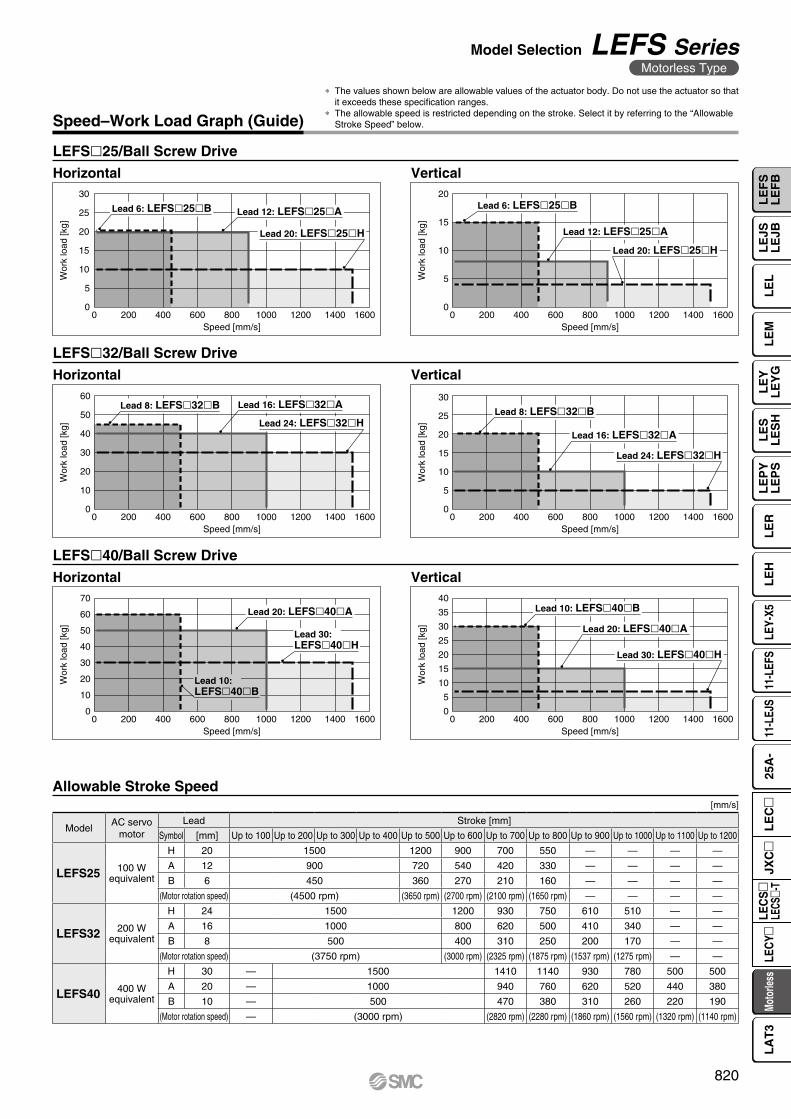
Speed–Work Load Graph (Guide)
LEFSl25/Ball Screw Drive
LEFSl40/Ball Screw Drive
LEFSl32/Ball Screw Drive
Horizontal Vertical
Horizontal Vertical
Horizontal Vertical
Allowable Stroke Speed[mm/s]
ModelAC servo
motorLead Stroke [mm]
Symbol [mm] Up to 100 Up to 200 Up to 300 Up to 400 Up to 500 Up to 600 Up to 700 Up to 800 Up to 900 Up to 1000 Up to 1100 Up to 1200
LEFS25 100 Wequivalent
H 20 1500 1200 900 700 550 — — — —
A 12 900 720 540 420 330 — — — —
B 6 450 360 270 210 160 — — — —
(Motor rotation speed) (4500 rpm) (3650 rpm) (2700 rpm) (2100 rpm) (1650 rpm) — — — —
LEFS32 200 Wequivalent
H 24 1500 1200 930 750 610 510 — —
A 16 1000 800 620 500 410 340 — —
B 8 500 400 310 250 200 170 — —
(Motor rotation speed) (3750 rpm) (3000 rpm) (2325 rpm) (1875 rpm) (1537 rpm) (1275 rpm) — —
LEFS40 400 Wequivalent
H 30 — 1500 1410 1140 930 780 500 500
A 20 — 1000 940 760 620 520 440 380
B 10 — 500 470 380 310 260 220 190
(Motor rotation speed) — (3000 rpm) (2820 rpm) (2280 rpm) (1860 rpm) (1560 rpm) (1320 rpm) (1140 rpm)
* The values shown below are allowable values of the actuator body. Do not use the actuator so that it exceeds these specification ranges.
* The allowable speed is restricted depending on the stroke. Select it by referring to the “Allowable Stroke Speed” below.
820
Model Selection LEFS SeriesMotorless Type
LE
FS
LE
FB
LE
LL
EJS
LE
JBL
EM
LE
YL
EY
GL
ES
LE
SH
LE
PY
LE
PS
LE
RL
EH
LEY-
X511
-LEF
S11
-LEJ
S25
A-
Moto
rless
LEC
Y�LE
CS
�LE
CS�-
TJX
C�
LE
C�
LA
T3
0
2500
5000
7500
10000
12500
15000
17500
20000
0 2 4 6 8 10
Work load [kg]
Acc
eler
atio
n/D
ecel
erat
ion
[mm
/s2] Duty ratio: 50%
Duty ratio: 75%
Duty ratio: 100%
Work load [kg]A
ccel
erat
ion/
Dec
eler
atio
n [m
m/s
2]
0
2500
5000
7500
10000
12500
15000
17500
20000
22500
0 1 2 3 4
Duty ratio: 50%
Duty ratio: 75%
Duty ratio: 100%
Work load [kg]
Acc
eler
atio
n/D
ecel
erat
ion
[mm
/s2]
0
2500
5000
7500
10000
12500
15000
17500
20000
0 5 10 15 20
Duty ratio: 50%
Duty ratio: 75%
Duty ratio: 100%
Work load [kg]
Acc
eler
atio
n/D
ecel
erat
ion
[mm
/s2]
0
2500
5000
7500
10000
12500
15000
17500
20000
0 5 10 15
Duty ratio: 50%
Duty ratio: 75%
Duty ratio: 100%
Work load [kg]
Acc
eler
atio
n/D
ecel
erat
ion
[mm
/s2]
0
2500
5000
7500
10000
12500
15000
17500
20000
0 5 10 15 20
Duty ratio: 50%
Duty ratio: 75%
Duty ratio: 100%
Work load [kg]
Acc
eler
atio
n/D
ecel
erat
ion
[mm
/s2]
0
2500
5000
7500
10000
12500
15000
17500
20000
0 2 4 6 8
Duty ratio: 50%
Duty ratio: 75%
Duty ratio: 100%
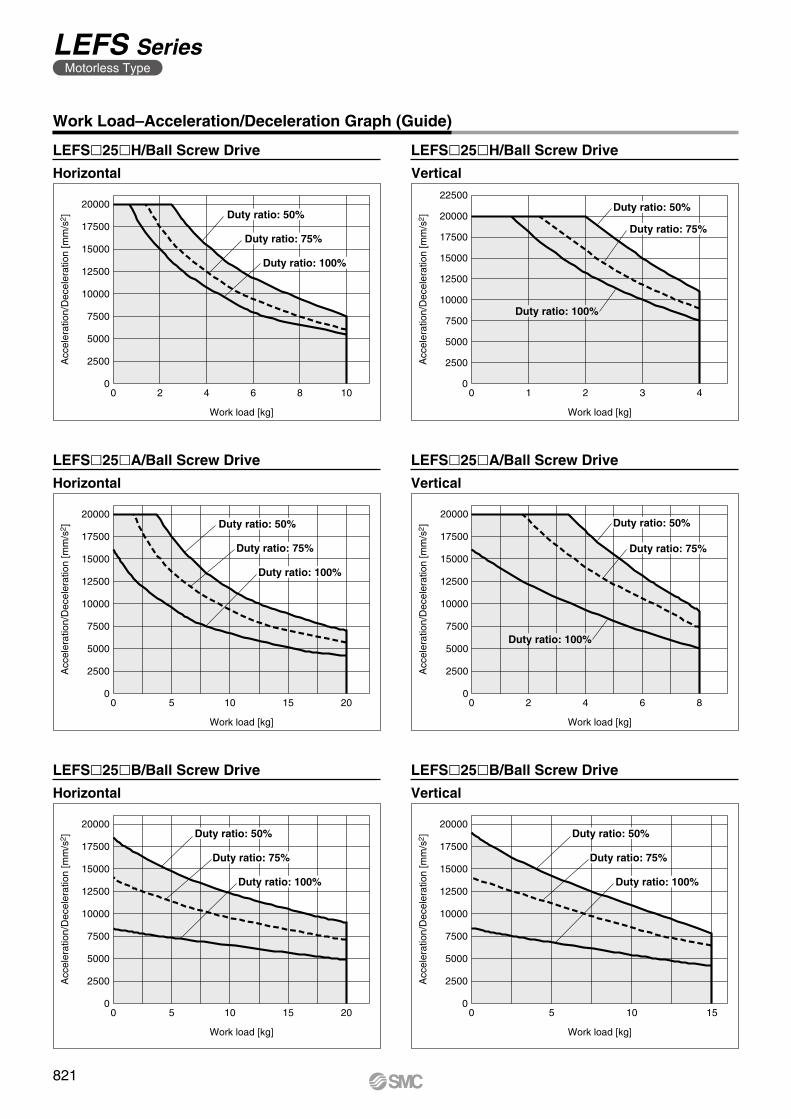
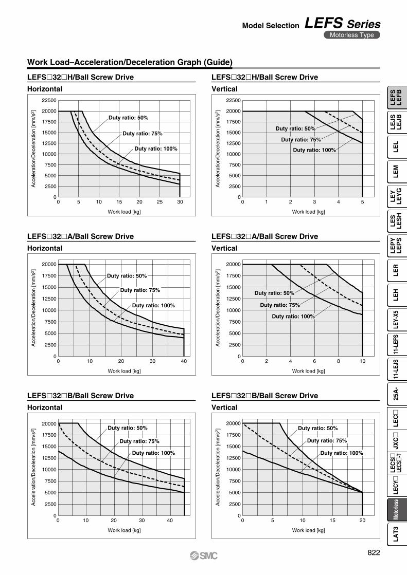
Work Load–Acceleration/Deceleration Graph (Guide)
Horizontal
Horizontal Vertical
LEFSl25lH/Ball Screw Drive
Horizontal Vertical
LEFSl25lA/Ball Screw Drive LEFSl25lA/Ball Screw Drive
LEFSl25lB/Ball Screw Drive LEFSl25lB/Ball Screw Drive
LEFSl25lH/Ball Screw Drive
Vertical
821
LEFS SeriesMotorless Type
Work load [kg]
Acc
eler
atio
n/D
ecel
erat
ion
[mm
/s2]
2500
5000
7500
10000
12500
15000
17500
20000
22500
5 10 15 20 25 300
0
Duty ratio: 50%
Duty ratio: 75%
Duty ratio: 100%
Work load [kg]A
ccel
erat
ion/
Dec
eler
atio
n [m
m/s
2]
0
2500
5000
7500
10000
12500
15000
17500
20000
22500
1 2 3 4 50
Duty ratio: 50%
Duty ratio: 75%
Duty ratio: 100%
0
2500
5000
7500
10000
12500
15000
17500
20000
0 10 20 30 40
Work load [kg]
Acc
eler
atio
n/D
ecel
erat
ion
[mm
/s2 ] Duty ratio: 50%
Duty ratio: 75%
Duty ratio: 100%
Work load [kg]
Acc
eler
atio
n/D
ecel
erat
ion
[mm
/s2]
0
2500
5000
7500
10000
12500
15000
17500
20000
0 5 10 15 20
Duty ratio: 50%
Duty ratio: 75%
Duty ratio: 100%
Work load [kg]
Acc
eler
atio
n/D
ecel
erat
ion
[mm
/s2]
0
2500
5000
7500
10000
12500
15000
17500
20000
0 10 20 30 40
Duty ratio: 50%
Duty ratio: 75%
Duty ratio: 100%
Work load [kg]
Acc
eler
atio
n/D
ecel
erat
ion
[mm
/s2]
0
2500
5000
7500
10000
12500
15000
17500
20000
0 2 4 6 8 10
Duty ratio: 50%
Duty ratio: 75%
Duty ratio: 100%
Work Load–Acceleration/Deceleration Graph (Guide)
Horizontal
Horizontal Vertical
LEFSl32lH/Ball Screw Drive
Horizontal Vertical
LEFSl32lA/Ball Screw Drive LEFSl32lA/Ball Screw Drive
LEFSl32lB/Ball Screw Drive LEFSl32lB/Ball Screw Drive
LEFSl32lH/Ball Screw Drive
Vertical
822
Model Selection LEFS SeriesMotorless Type
LE
FS
LE
FB
LE
LL
EJS
LE
JBL
EM
LE
YL
EY
GL
ES
LE
SH
LE
PY
LE
PS
LE
RL
EH
LEY-
X511
-LEF
S11
-LEJ
S25
A-
Moto
rless
LEC
Y�LE
CS
�LE
CS�-
TJX
C�
LE
C�
LA
T3
Work load [kg]
Acc
eler
atio
n/D
ecel
erat
ion
[mm
/s2]
2500
5000
7500
10000
12500
15000
17500
20000
22500
0 5 10 15 20 25 300
Duty ratio: 50%
Duty ratio: 75%
Duty ratio: 100%
Work load [kg]A
ccel
erat
ion/
Dec
eler
atio
n [m
m/s
2]
0
2500
5000
7500
10000
12500
15000
17500
20000
22500
0 1 2 3 4 5 6 7
Duty ratio: 50%
Duty ratio: 75%
Duty ratio: 100%
Work load [kg]
Acc
eler
atio
n/D
ecel
erat
ion
[mm
/s2]
0
2500
5000
7500
10000
12500
15000
17500
20000
22500
0 10 20 30 40 50 60
Duty ratio: 50%
Duty ratio: 75%
Duty ratio: 100%
Work load [kg]
Acc
eler
atio
n/D
ecel
erat
ion
[mm
/s2]
0
2500
5000
7500
10000
12500
15000
17500
20000
22500
0 10 20 30
Duty ratio: 50%
Duty ratio: 75%
Duty ratio: 100%
Work load [kg]
Acc
eler
atio
n/D
ecel
erat
ion
[mm
/s2]
0
7500
10000
12500
15000
17500
20000
22500
0 10 20 30 40 50
2500
5000
Duty ratio: 50%
Duty ratio: 75%
Duty ratio: 100%
Work load [kg]
Acc
eler
atio
n/D
ecel
erat
ion
[mm
/s2]
0
2500
5000
7500
10000
12500
15000
17500
20000
22500
0 5 10 15
Duty ratio: 50%
Duty ratio: 75%
Duty ratio: 100%
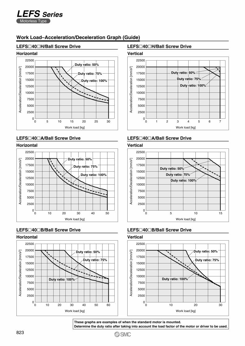
Work Load–Acceleration/Deceleration Graph (Guide)
Horizontal
Horizontal Vertical
LEFSl40lH/Ball Screw Drive
Horizontal Vertical
LEFSl40lA/Ball Screw Drive LEFSl40lA/Ball Screw Drive
LEFSl40lB/Ball Screw Drive LEFSl40lB/Ball Screw Drive
LEFSl40lH/Ball Screw Drive
Vertical
These graphs are examples of when the standard motor is mounted.Determine the duty ratio after taking into account the load factor of the motor or driver to be used.
823
LEFS SeriesMotorless Type
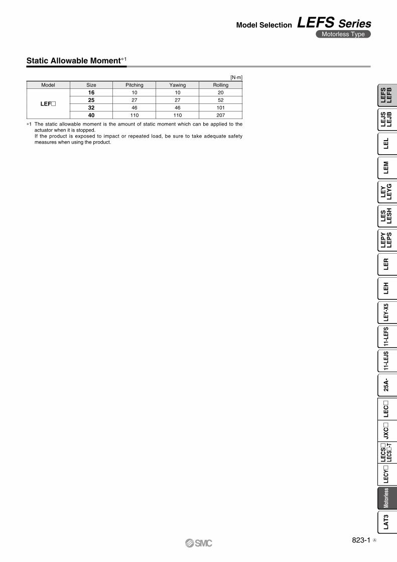
Static Allowable Moment∗1
[N·m]
Model Size Pitching Yawing Rolling
LEFm
16 10 10 20
25 27 27 52
32 46 46 101
40 110 110 207
∗1 The static allowable moment is the amount of static moment which can be applied to the actuator when it is stopped.If the product is exposed to impact or repeated load, be sure to take adequate safety measures when using the product.
823-1
Model Selection LEFS SeriesMotorless Type
LE
FS
LE
FB
LE
LL
EJS
LE
JBL
EM
LE
YL
EY
GL
ES
LE
SH
LE
PY
LE
PS
LE
RL
EH
LEY-
X511
-LEF
S11
-LEJ
S25
A-
Moto
rless
LEC
Y�LE
CS
�LE
CS�-
TJX
C�
LE
C�
LA
T3
A

L1
L3
Mep
m
L5
Mey
m
L4
Merm
L2
L6
0 10 20 30 40 50 60Work load [kg]
L1
[mm
]
0
500
1500
1000
0 10 20 30 40Work load [kg]
L1
[mm
]
0
500
1500
1000
0 5 10 15 20Work load [kg]
L1
[mm
]
0
500
1500
1000
0 10 20 30 40 50 60Work load [kg]
L3
[mm
]
0
500
1500
1000
0 10 20 30 40Work load [kg]
L3
[mm
]
0
500
1500
1000
0 5 10 15 20Work load [kg]
L3
[mm
]
0
500
1500
1000
0 10 20 30 40 50 60Work load [kg]
L4
[mm
]
0
500
1500
1000
0 10 20 30 40Work load [kg]
L4
[mm
]
0
500
1500
1000
0 5 10 15 20Work load [kg]
L4
[mm
]
0
500
1500
1000
0 10 20 30 40 50 60Work load [kg]
L5
[mm
]
0
500
1500
1000
0 10 20 30 40Work load [kg]
L5
[mm
]
0
500
1500
1000
0 5 10 15 20Work load [kg]
L5
[mm
]
0
500
1500
1000
0 10 20 30 40 50 60Work load [kg]
L2
[mm
]
0 10 20 30 40Work load [kg]
L2
[mm
]
0 5 10 15 20Work load [kg]
L2
[mm
]
0
600
400
200
1000
800
0
600
400
200
1000
800
0
600
400
200
1000
800
0 10 20 30 40 50 60Work load [kg]
L6
[mm
]
0 10 20 30 40Work load [kg]
L6
[mm
]
0 5 10 15 20Work load [kg]
L6
[mm
]
0
600
400
200
1000
800
0
600
400
200
1000
800
0
600
400
200
1000
800
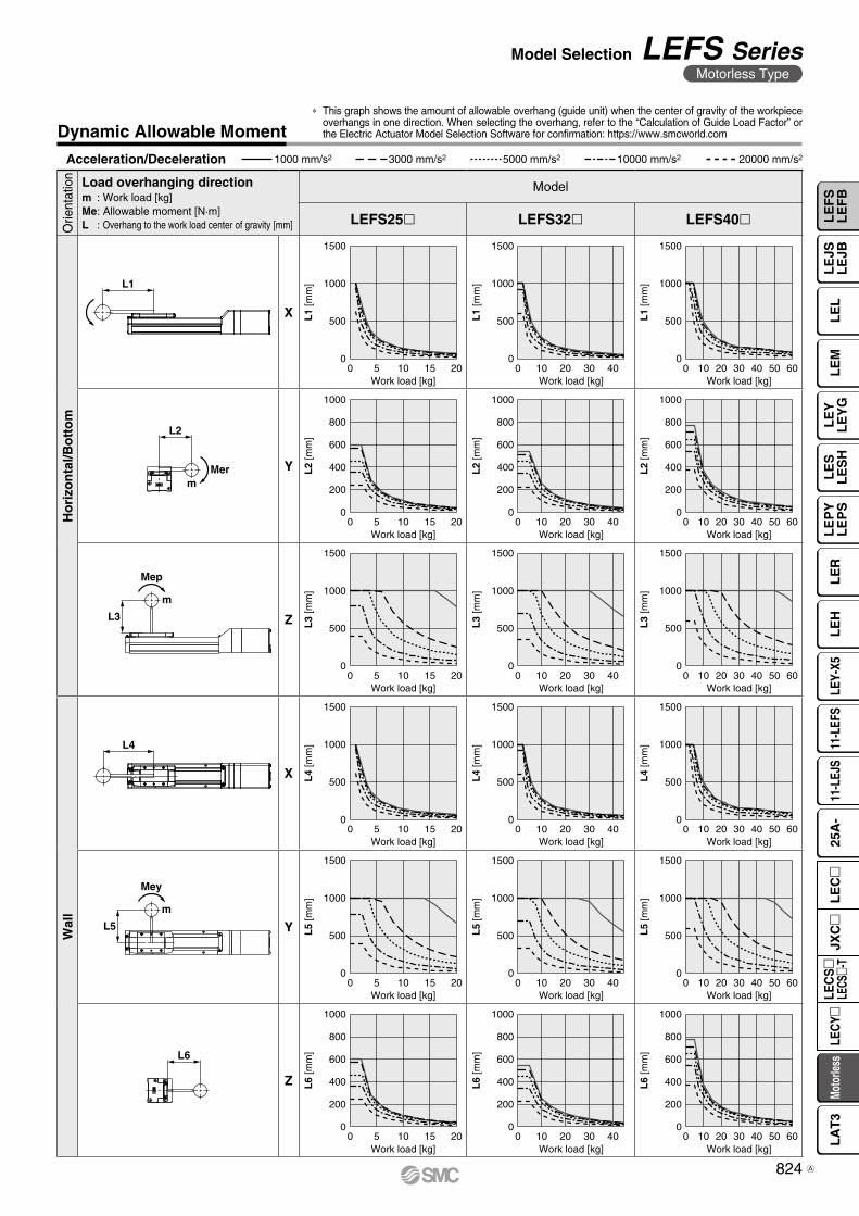
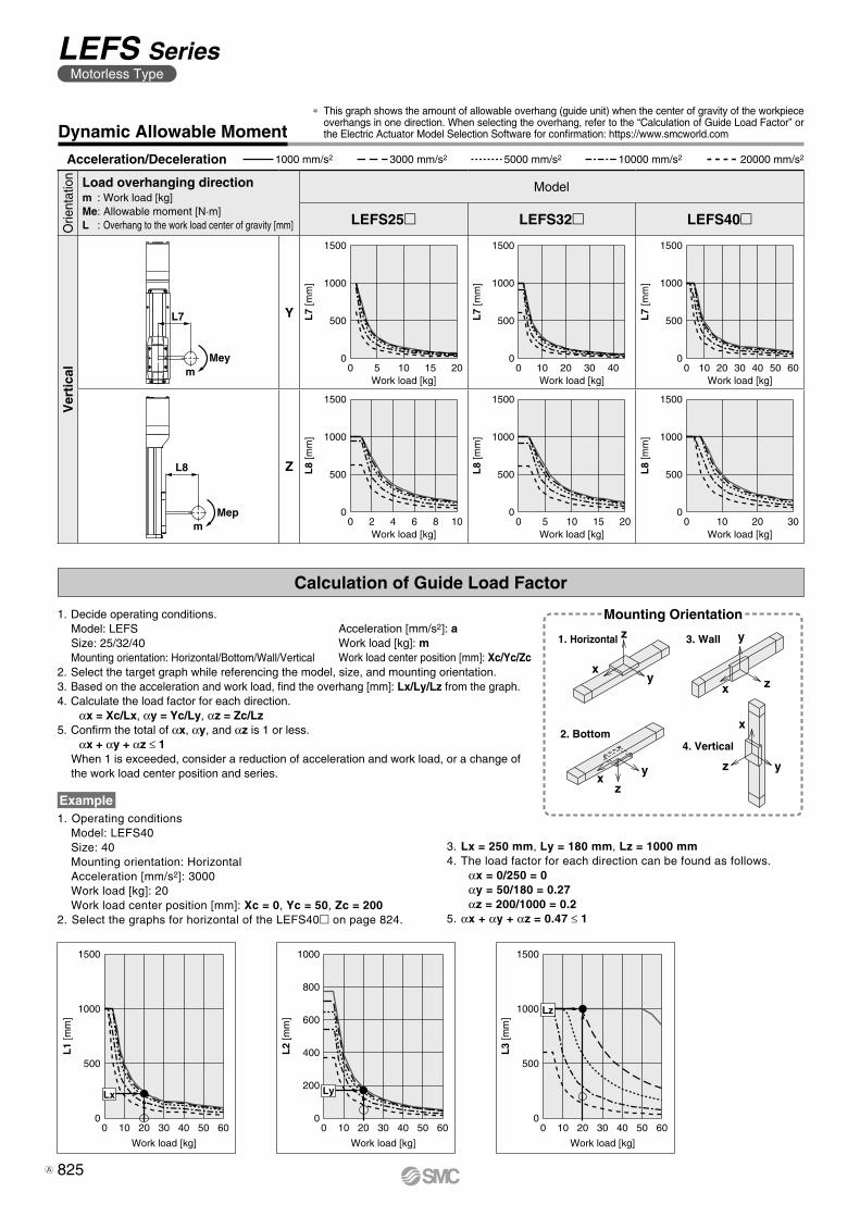
Dynamic Allowable Moment* This graph shows the amount of allowable overhang (guide unit) when the center of gravity of the workpiece
overhangs in one direction. When selecting the overhang, refer to the “Calculation of Guide Load Factor” or the Electric Actuator Model Selection Software for confirmation: https://www.smcworld.com
Acceleration/Deceleration 1000 mm/s2 3000 mm/s2 5000 mm/s2 10000 mm/s2 20000 mm/s2
Orie
ntat
ion Load overhanging direction
m : Work load [kg]Me: Allowable moment [N·m]L : Overhang to the work load center of gravity [mm]
Model
LEFS25 LEFS32 LEFS40
Ho
rizo
nta
l/Bo
tto
m
X
Y
Z
Wal
l
X
Y
Z
824
Model Selection LEFS SeriesMotorless Type
LE
FS
LE
FB
LE
LL
EJS
LE
JBL
EM
LE
YL
EY
GL
ES
LE
SH
LE
PY
LE
PS
LE
RL
EH
LEY-
X511
-LEF
S11
-LEJ
S25
A-
Moto
rless
LEC
Y�LE
CS
�LE
CS�-
TJX
C�
LE
C�
LA
T3
A
L8
Mepm
L7
Meym
xy
z
x z
y
xy
z
x
z y
0 10 20 30 40 50 60Work load [kg]
L7
[mm
]
500
1500
1000
0 10 20 30 40Work load [kg]
L7
[mm
]
500
1500
1000
0 5 10 2015Work load [kg]
L7
[mm
]
0
500
1500
1000
0 10 20 30Work load [kg]
L8
[mm
]
500
1500
1000
0 5 10 15 20Work load [kg]
L8
[mm
]500
1500
1000
0 4 62 8 10Work load [kg]
L8
[mm
]
500
1500
1000
0 0
0 0 0
0 10 20 30 40 50 600
500
1500
1000
Lx
L1
[mm
]
Work load [kg]
0 10 20 30 40 50 600
600
400
200
1000
800
L2
[mm
]
Work load [kg]
Ly
0 10 20 30 40 50 600
500
1500
1000
L3
[mm
]
Work load [kg]
Lz
Orie
ntat
ion Load overhanging direction
m : Work load [kg]Me: Allowable moment [N·m]L : Overhang to the work load center of gravity [mm]
Model
LEFS25m LEFS32m LEFS40m
Ver
tica
l
Y
Z
Acceleration/Deceleration 1000 mm/s2 3000 mm/s2 5000 mm/s2 10000 mm/s2 20000 mm/s2
Dynamic Allowable Moment* This graph shows the amount of allowable overhang (guide unit) when the center of gravity of the workpiece
overhangs in one direction. When selecting the overhang, refer to the “Calculation of Guide Load Factor” or the Electric Actuator Model Selection Software for confirmation: https://www.smcworld.com
Acceleration [mm/s2]: aWork load [kg]: mWork load center position [mm]: Xc/Yc/Zc
1. Decide operating conditions.Model: LEFSSize: 25/32/40Mounting orientation: Horizontal/Bottom/Wall/Vertical
2. Select the target graph while referencing the model, size, and mounting orientation.3. Based on the acceleration and work load, find the overhang [mm]: Lx/Ly/Lz from the graph.4. Calculate the load factor for each direction.
αx = Xc/Lx, αy = Yc/Ly, αz = Zc/Lz5. Confirm the total of αx, αy, and αz is 1 or less.
αx + αy + αz ≤ 1When 1 is exceeded, consider a reduction of acceleration and work load, or a change of the work load center position and series.
Mounting Orientation
1. Horizontal 3. Wall
2. Bottom4. Vertical
1. Operating conditionsModel: LEFS40Size: 40Mounting orientation: HorizontalAcceleration [mm/s2]: 3000Work load [kg]: 20Work load center position [mm]: Xc = 0, Yc = 50, Zc = 200
2. Select the graphs for horizontal of the LEFS40m on page 824.
3. Lx = 250 mm, Ly = 180 mm, Lz = 1000 mm4. The load factor for each direction can be found as follows.
αx = 0/250 = 0αy = 50/180 = 0.27αz = 200/1000 = 0.2
5. αx + αy + αz = 0.47 ≤ 1
Calculation of Guide Load Factor
Example
825
LEFS SeriesMotorless Type
A
w
q
A side
C side
B side
D side
WL
LEFS25 (L = 25 mm)
LEFS40 (L = 37 mm)
LEFS32 (L = 30 mm)
0.08
0.06
0.04
0.02
00 100 200 300 400 500
Dis
plac
emen
t [m
m]
Load W [N]
LEF25
LEF32
LEF40
0
0.05
0.1
0.15
0.2
0.25
0 100 200 300
Dis
plac
emen
t [m
m]
Overhang distance [mm]
Dis
plac
emen
t [m
m]
0
0.02
0.04
0.06
0.08
0.1
0.12
0 100 200 300
Overhang distance [mm]
LEF25
LEF32
LEF40
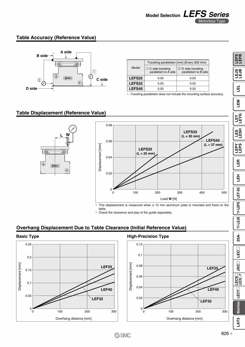
∗ This displacement is measured when a 15 mm aluminum plate is mounted and fixed on the table.
∗ Check the clearance and play of the guide separately.
Table Accuracy (Reference Value)
∗ Traveling parallelism does not include the mounting surface accuracy.
Table Displacement (Reference Value)
Model
Traveling parallelism [mm] (Every 300 mm)
q C side travelingparallelism to A side
w D side travelingparallelism to B side
LEFS25 0.05 0.03
LEFS32 0.05 0.03
LEFS40 0.05 0.03
Overhang Displacement Due to Table Clearance (Initial Reference Value)
Basic Type High-Precision Type
826
Model Selection LEFS SeriesMotorless Type
LE
FS
LE
FB
LE
LL
EJS
LE
JBL
EM
LE
YL
EY
GL
ES
LE
SH
LE
PY
LE
PS
LE
RL
EH
LEY-
X511
-LEF
S11
-LEJ
S25
A-
Moto
rless
LEC
Y�LE
CS
�LE
CS�-
TJX
C�
LE
C�
LA
T3
A
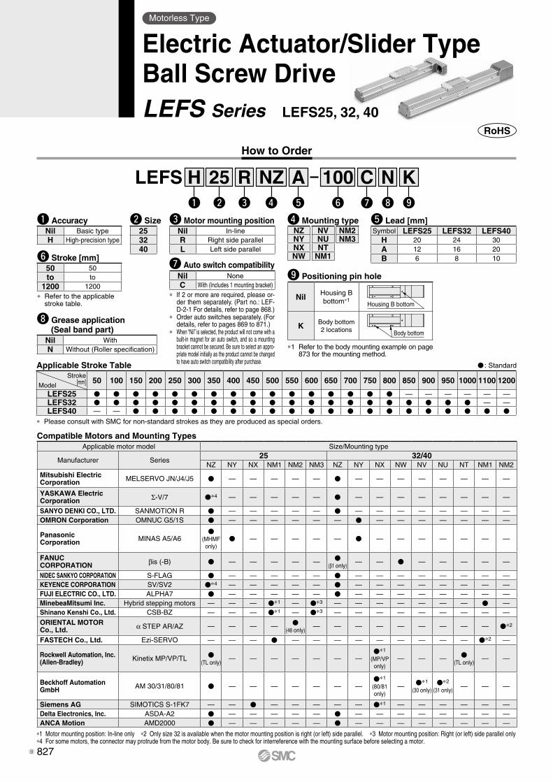
How to Order
Motorless Type
Electric Actuator/Slider TypeBall Screw DriveLEFS Series LEFS25, 32, 40
Compatible Motors and Mounting Types
*1 Motor mounting position: In-line only *2 Only size 32 is available when the motor mounting position is right (or left) side parallel. *3 Motor mounting position: Right (or left) side parallel only*4 For some motors, the connector may protrude from the motor body. Be sure to check for interreference with the mounting surface before selecting a motor.
t Lead [mm]Symbol LEFS25 LEFS32 LEFS40
H 20 24 30A 12 16 20B 6 8 10
q AccuracyNil Basic typeH High-precision type
y Stroke [mm]
* Refer to the applicable stroke table.
50 50to to
1200 1200
e Motor mounting positionNil In-lineR Right side parallelL Left side parallel
w Size253240
i Grease application (Seal band part)
Nil WithN Without (Roller specification)
o Positioning pin hole
Nil Housing B bottom*1
Housing B bottom
K Body bottom2 locations Body bottom
*1 Refer to the body mounting example on page 873 for the mounting method.
u Auto switch compatibilityNil NoneC With (Includes 1 mounting bracket)
* If 2 or more are required, please or-der them separately. (Part no.: LEF-D-2-1 For details, refer to page 868.)
* Order auto switches separately. (For details, refer to pages 869 to 871.)
* When “Nil” is selected, the product will not come with a built-in magnet for an auto switch, and so a mounting bracket cannot be secured. Be sure to select an appro-priate model initially as the product cannot be changed to have auto switch compatibility after purchase.
LEFS 100A25w r t
H Rq e y
NZ Ni
Cu
Ko
Applicable Stroke TableStroke
[mm]Model50 100 150 200 250 300 350 400 450 500 550 600 650 700 750 800 850 900 950 1000 1100 1200
LEFS25 — — — — — —LEFS32 — —LEFS40 — —
* Please consult with SMC for non-standard strokes as they are produced as special orders.
: Standard
r Mounting typeNZ NV NM2NY NU NM3NX NTNW NM1
Applicable motor model Size/Mounting type
Manufacturer Series25 32/40
NZ NY NX NM1 NM2 NM3 NZ NY NX NW NV NU NT NM1 NM2
Mitsubishi ElectricCorporation MELSERVO JN/J4/J5 — — — — — — — — — — — — —
YASKAWA Electric Corporation Σ-V/7 *4 — — — — — — — — — — — — —
SANYO DENKI CO., LTD. SANMOTION R — — — — — — — — — — — — —OMRON Corporation OMNUC G5/1S — — — — — — — — — — — — —
PanasonicCorporation MINAS A5/A6
(MHMF
only) — — — — — — — — — — — —
FANUCCORPORATION βis (-B) — — — — —
(β1 only)— — — — — — —
NIDEC SANKYO CORPORATION S-FLAG — — — — — — — — — — — — —KEYENCE CORPORATION SV/SV2 *4 — — — — — — — — — — — — —FUJI ELECTRIC CO., LTD. ALPHA7 — — — — — — — — — — — — —MinebeaMitsumi Inc. Hybrid stepping motors — — — *1 — *3 — — — — — — — —Shinano Kenshi Co., Ltd. CSB-BZ — — — *1 — *3 — — — — — — — — —
ORIENTAL MOTOR Co., Ltd. α STEP AR/AZ — — — —
(46 only)— — — — — — — — — *2
FASTECH Co., Ltd. Ezi-SERVO — — — — — — — — — — — — *2 —
Rockwell Automation, Inc.(Allen-Bradley) Kinetix MP/VP/TL
(TL only)— — — — — — —
*1
(MP/VPonly)
— — — (TL only)
— —
Beckhoff AutomationGmbH AM 30/31/80/81 — — — — — — —
*1
(80/81only)
— *1
(30 only)*2
(31 only)— — —
Siemens AG SIMOTICS S-1FK7 — — — — — — — *1 — — — — — —Delta Electronics, Inc. ASDA-A2 — — — — — — — — — — — — —ANCA Motion AMD2000 — — — — — — — — — — — — —
827B
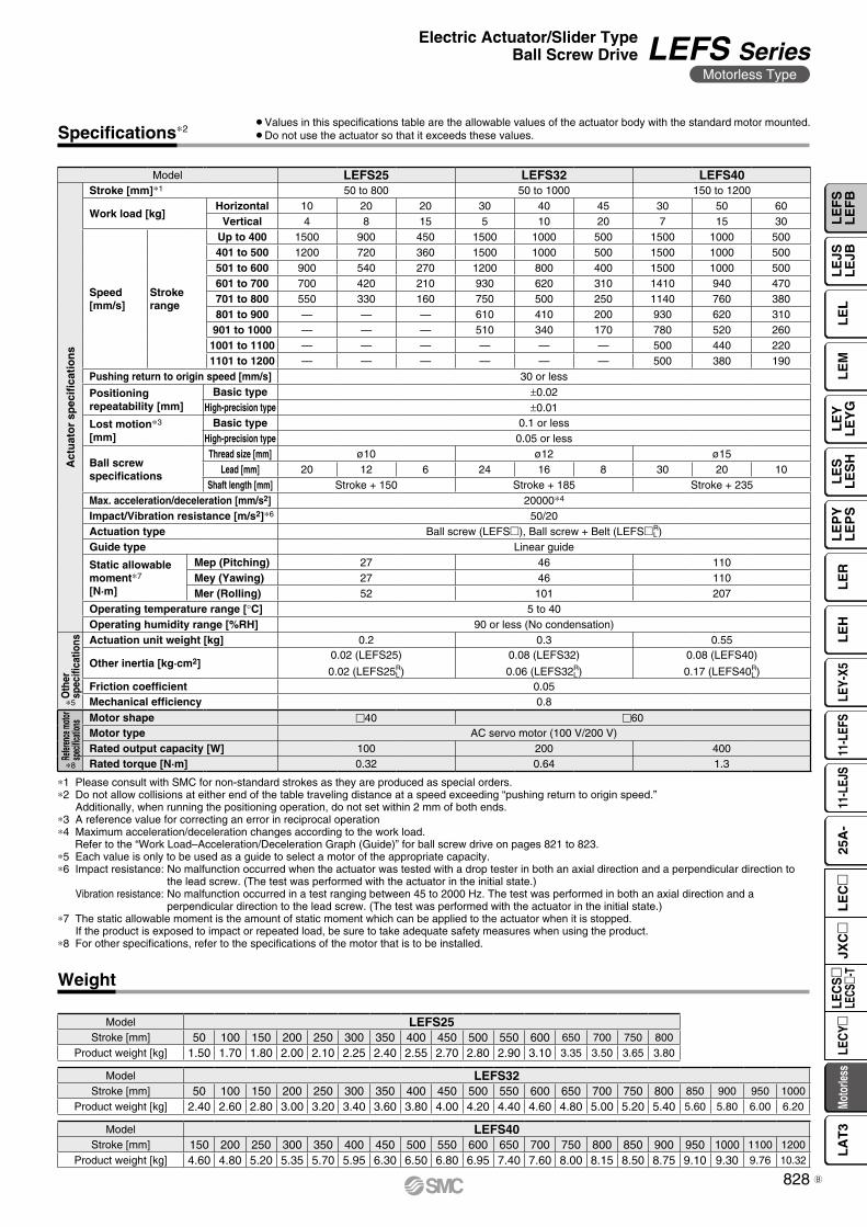
Specifications∗2
Weight
∗1 Please consult with SMC for non-standard strokes as they are produced as special orders.∗2 Do not allow collisions at either end of the table traveling distance at a speed exceeding “pushing return to origin speed.”
Additionally, when running the positioning operation, do not set within 2 mm of both ends.∗3 A reference value for correcting an error in reciprocal operation∗4 Maximum acceleration/deceleration changes according to the work load.
Refer to the “Work Load–Acceleration/Deceleration Graph (Guide)” for ball screw drive on pages 821 to 823.∗5 Each value is only to be used as a guide to select a motor of the appropriate capacity.∗6 Impact resistance: No malfunction occurred when the actuator was tested with a drop tester in both an axial direction and a perpendicular direction to
the lead screw. (The test was performed with the actuator in the initial state.)Vibration resistance: No malfunction occurred in a test ranging between 45 to 2000 Hz. The test was performed in both an axial direction and a
perpendicular direction to the lead screw. (The test was performed with the actuator in the initial state.)∗7 The static allowable moment is the amount of static moment which can be applied to the actuator when it is stopped.
If the product is exposed to impact or repeated load, be sure to take adequate safety measures when using the product.∗8 For other specifications, refer to the specifications of the motor that is to be installed.
Model LEFS25 LEFS32 LEFS40
Act
uat
or
spec
ifica
tio
ns
Stroke [mm]∗1 50 to 800 50 to 1000 150 to 1200
Work load [kg]Horizontal 10 20 20 30 40 45 30 50 60
Vertical 4 8 15 5 10 20 7 15 30
Speed[mm/s]
Strokerange
Up to 400 1500 900 450 1500 1000 500 1500 1000 500401 to 500 1200 720 360 1500 1000 500 1500 1000 500501 to 600 900 540 270 1200 800 400 1500 1000 500601 to 700 700 420 210 930 620 310 1410 940 470701 to 800 550 330 160 750 500 250 1140 760 380801 to 900 — — — 610 410 200 930 620 310
901 to 1000 — — — 510 340 170 780 520 2601001 to 1100 — — — — — — 500 440 2201101 to 1200 — — — — — — 500 380 190
Pushing return to origin speed [mm/s] 30 or less
Positioning repeatability [mm]
Basic type ±0.02High-precision type ±0.01
Lost motion∗3
[mm]Basic type 0.1 or less
High-precision type 0.05 or less
Ball screw specifications
Thread size [mm] ø10 ø12 ø15Lead [mm] 20 12 6 24 16 8 30 20 10
Shaft length [mm] Stroke + 150 Stroke + 185 Stroke + 235Max. acceleration/deceleration [mm/s2] 20000∗4
Impact/Vibration resistance [m/s2]∗6 50/20Actuation type Ball screw (LEFS), Ball screw + Belt (LEFSR
L)Guide type Linear guide
Static allowable moment∗7
[N·m]
Mep (Pitching) 27 46 110Mey (Yawing) 27 46 110Mer (Rolling) 52 101 207
Operating temperature range [°C] 5 to 40Operating humidity range [%RH] 90 or less (No condensation)
Oth
ersp
ecifi
catio
ns Actuation unit weight [kg] 0.2 0.3 0.55
Other inertia [kg·cm2]0.02 (LEFS25)
0.02 (LEFS25R L)
0.08 (LEFS32)
0.06 (LEFS32R L)
0.08 (LEFS40)
0.17 (LEFS40R L)
Friction coefficient 0.05Mechanical efficiency 0.8
Refer
ence
moto
rsp
ecific
ation
s Motor shape 40 60Motor type AC servo motor (100 V/200 V)Rated output capacity [W] 100 200 400Rated torque [N·m] 0.32 0.64 1.3
Model LEFS25Stroke [mm] 50 100 150 200 250 300 350 400 450 500 550 600 650 700 750 800
Product weight [kg] 1.50 1.70 1.80 2.00 2.10 2.25 2.40 2.55 2.70 2.80 2.90 3.10 3.35 3.50 3.65 3.80
Model LEFS40Stroke [mm] 150 200 250 300 350 400 450 500 550 600 650 700 750 800 850 900 950 1000 1100 1200
Product weight [kg] 4.60 4.80 5.20 5.35 5.70 5.95 6.30 6.50 6.80 6.95 7.40 7.60 8.00 8.15 8.50 8.75 9.10 9.30 9.76 10.32
Model LEFS32Stroke [mm] 50 100 150 200 250 300 350 400 450 500 550 600 650 700 750 800 850 900 950 1000
Product weight [kg] 2.40 2.60 2.80 3.00 3.20 3.40 3.60 3.80 4.00 4.20 4.40 4.60 4.80 5.00 5.20 5.40 5.60 5.80 6.00 6.20
¡Values in this specifications table are the allowable values of the actuator body with the standard motor mounted.¡Do not use the actuator so that it exceeds these values.
∗5
∗8
828
Electric Actuator/Slider TypeBall Screw Drive LEFS Series
Motorless Type
LE
FS
LE
FB
LE
LL
EJS
LE
JBL
EM
LE
YL
EY
GL
ES
LE
SH
LE
PY
LE
PS
LE
RL
EH
LEY-
X511
-LEF
S11
-LEJ
S25
A-
Moto
rless
LEC
Y�LE
CS
�LE
CS�-
TJX
C�
LE
C�
LA
T3
B
(102)
64
45
38
3H9 ( )depth 3
3.5
4 x M5 x 0.8thread depth 8.5
Body mountingreference plane(B dimension range)∗1
LA (Table traveling distance) 52 31.5 FF
4748
38.5 Motor
Motor flange
10 (52)
(48)
24
58
38
6.5
6M4 x 0.7thread depth 8(F.G. terminal)
3H9 ( )depth 34
n x ø4.5
10F120
D x 120 (= E)
B
48
4 x FAthread depth FB45°
50
Motor mating part:øFD, depth FE
Mounting pitch: FC
Motor mating part:øFD, depth FE
4 x FAFG depth of counterbore FH∗ Spot facing is on the reverse side.
Mounting pitch: FC
ø3H9 ( )depth 3
+0.0250
+0.0250
+0.0250
Applicable motor dimensionsø
FD
FC
FA(FC)FK
FEøF
J
Dimensions: Ball Screw Drive
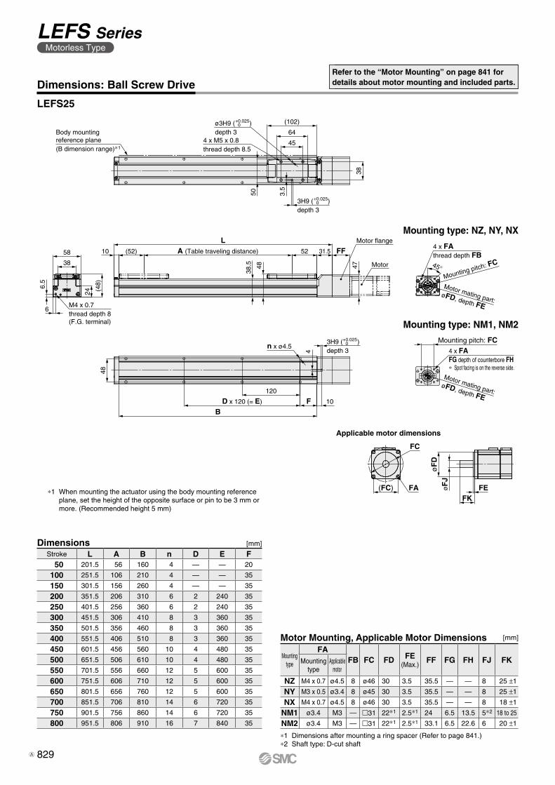
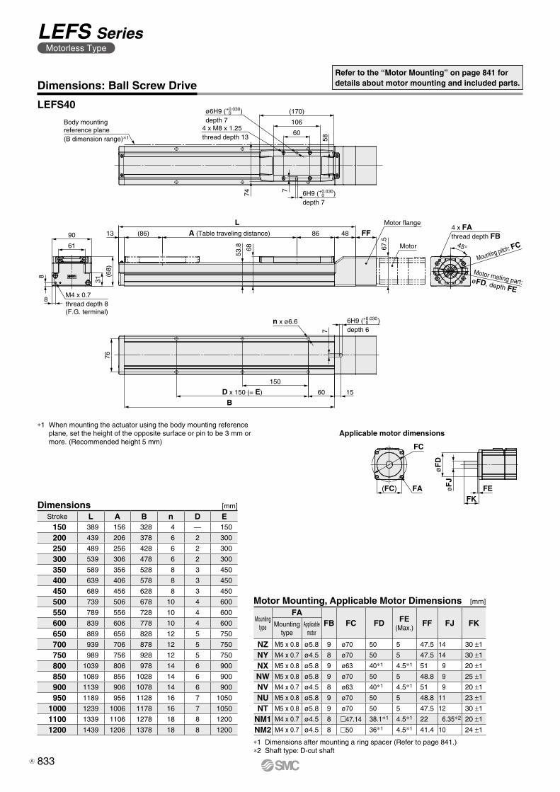
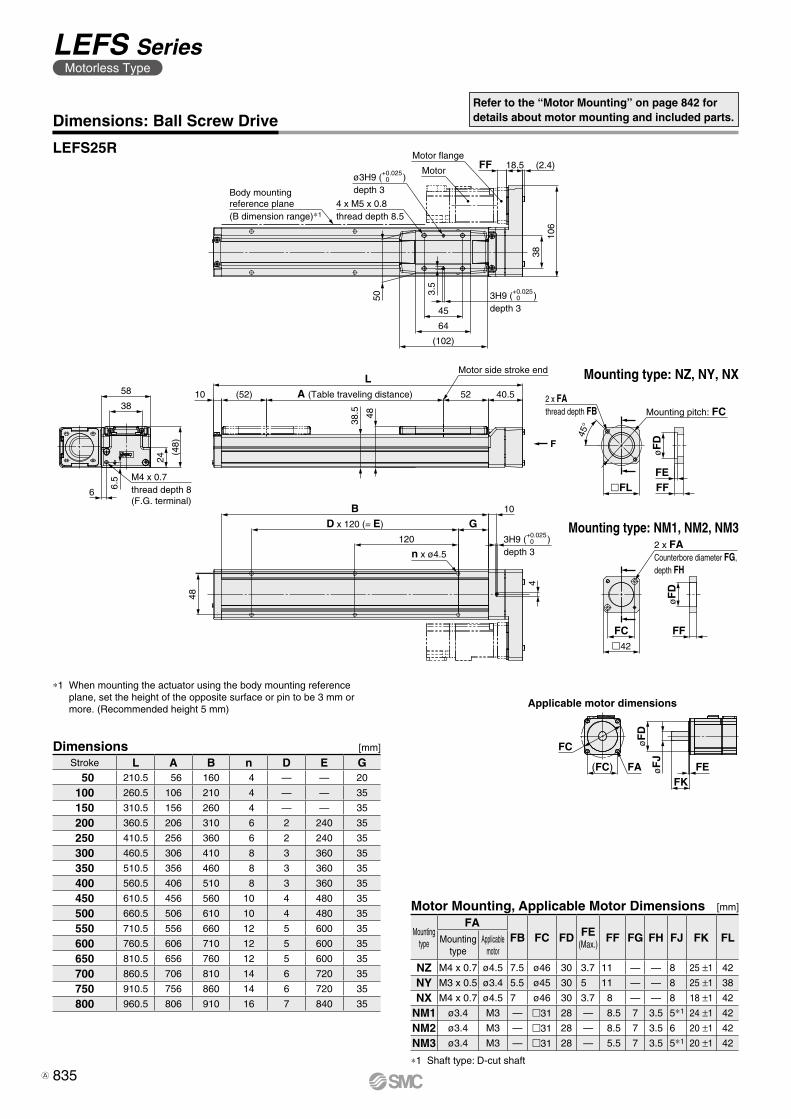
LEFS25
Refer to the “Motor Mounting” on page 841 for details about motor mounting and included parts.
Mounting type: NM1, NM2
Mounting type: NZ, NY, NX
Dimensions [mm]
Stroke L A B n D E F50 201.5 56 160 4 — — 20
100 251.5 106 210 4 — — 35
150 301.5 156 260 4 — — 35
200 351.5 206 310 6 2 240 35
250 401.5 256 360 6 2 240 35
300 451.5 306 410 8 3 360 35
350 501.5 356 460 8 3 360 35
400 551.5 406 510 8 3 360 35
450 601.5 456 560 10 4 480 35
500 651.5 506 610 10 4 480 35
550 701.5 556 660 12 5 600 35
600 751.5 606 710 12 5 600 35
650 801.5 656 760 12 5 600 35
700 851.5 706 810 14 6 720 35
750 901.5 756 860 14 6 720 35
800 951.5 806 910 16 7 840 35
∗1 When mounting the actuator using the body mounting reference plane, set the height of the opposite surface or pin to be 3 mm or more. (Recommended height 5 mm)
Motor Mounting, Applicable Motor Dimensions [mm]
Mounting type
FAFB FC FD FE
(Max.)FF FG FH FJ FKMounting
typeApplicable
motor
NZ M4 x 0.7 ø4.5 8 ø46 30 3.5 35.5 — — 8 25 ±1
NY M3 x 0.5 ø3.4 8 ø45 30 3.5 35.5 — — 8 25 ±1
NX M4 x 0.7 ø4.5 8 ø46 30 3.5 35.5 — — 8 18 ±1
NM1 ø3.4 M3 — m31 22∗1 2.5∗1 24 6.5 13.5 5∗2 18 to 25
NM2 ø3.4 M3 — m31 22∗1 2.5∗1 33.1 6.5 22.6 6 20 ±1
∗1 Dimensions after mounting a ring spacer (Refer to page 841.)∗2 Shaft type: D-cut shaft
829
LEFS SeriesMotorless Type
A
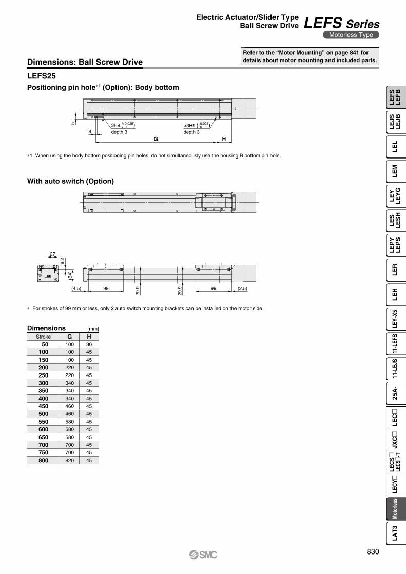
5
8
G H
+0.0250
+0.02503H9 ( )
depth 3ø3H9 ( )depth 3
27
8.2
(34)
(4.5) 99
29.9
29.9 99 (2.5)
Dimensions: Ball Screw DriveRefer to the “Motor Mounting” on page 841 for details about motor mounting and included parts.
Dimensions [mm]
LEFS25
∗1 When using the body bottom positioning pin holes, do not simultaneously use the housing B bottom pin hole.
Stroke G H50 100 30
100 100 45
150 100 45
200 220 45
250 220 45
300 340 45
350 340 45
400 340 45
450 460 45
500 460 45
550 580 45
600 580 45
650 580 45
700 700 45
750 700 45
800 820 45
Positioning pin hole∗1 (Option): Body bottom
With auto switch (Option)
∗ For strokes of 99 mm or less, only 2 auto switch mounting brackets can be installed on the motor side.
830
Electric Actuator/Slider TypeBall Screw Drive LEFS Series
Motorless Type
LE
FS
LE
FB
LE
LL
EJS
LE
JBL
EM
LE
YL
EY
GL
ES
LE
SH
LE
PY
LE
PS
LE
RL
EH
LEY-
X511
-LEF
S11
-LEJ
S25
A-
Moto
rless
LEC
Y�LE
CS
�LE
CS�-
TJX
C�
LE
C�
LA
T3
Motor mating part:øFD, depth FE
Mounting pitch: FCMotor
Motor flange
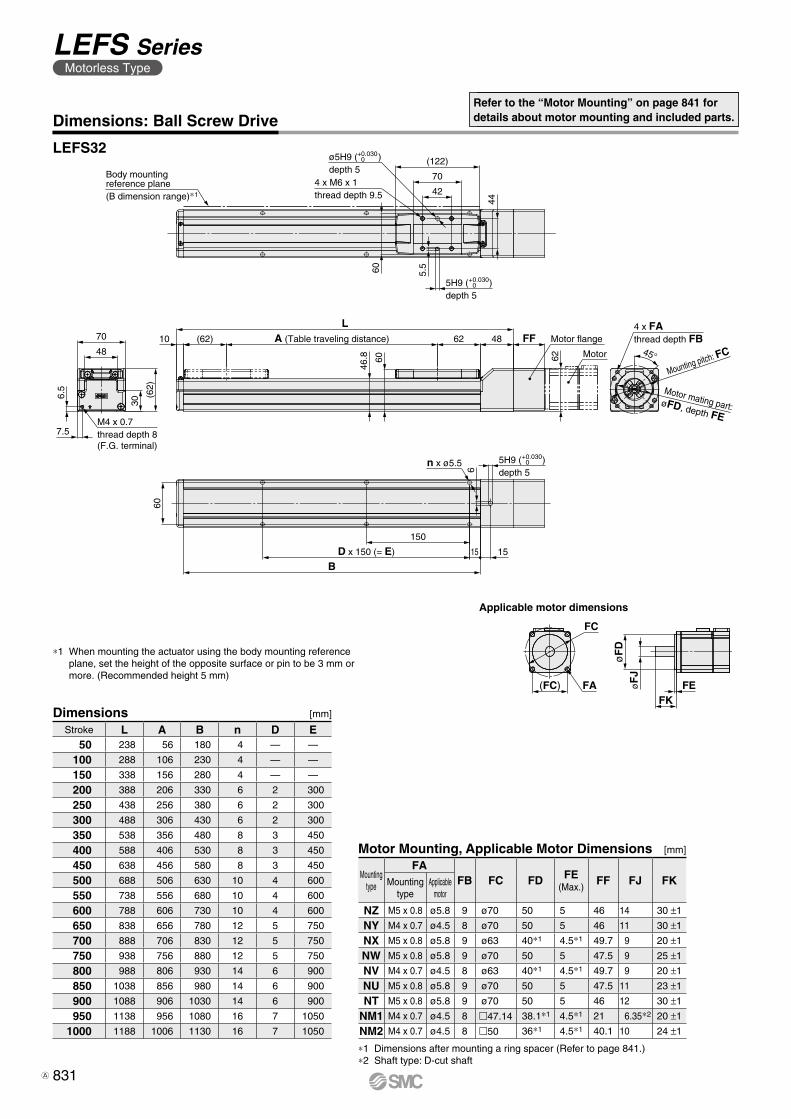
(122)
44
70
424 x M6 x 1thread depth 9.5
5H9 ( )depth 5
5.560
62
FF4862A (Table traveling distance)
L10 (62)
46.8 60
BD x 150 (= E)
150
1515
n x ø5.56
5H9 ( )depth 5
60(6
2)
30
70
48
6.5
7.5M4 x 0.7thread depth 8(F.G. terminal)
45°
4 x FA thread depth FB
+0.0300
+0.0300
ø5H9 ( )depth 5
+0.0300
Body mountingreference plane(B dimension range)∗1
Applicable motor dimensionsø
FD
FC
FA(FC)FK
FEøF
J
Dimensions: Ball Screw DriveRefer to the “Motor Mounting” on page 841 for details about motor mounting and included parts.
LEFS32
∗1 When mounting the actuator using the body mounting reference plane, set the height of the opposite surface or pin to be 3 mm or more. (Recommended height 5 mm)
Dimensions [mm]
Stroke L A B n D E50 238 56 180 4 — —
100 288 106 230 4 — —
150 338 156 280 4 — —
200 388 206 330 6 2 300
250 438 256 380 6 2 300
300 488 306 430 6 2 300
350 538 356 480 8 3 450
400 588 406 530 8 3 450
450 638 456 580 8 3 450
500 688 506 630 10 4 600
550 738 556 680 10 4 600
600 788 606 730 10 4 600
650 838 656 780 12 5 750
700 888 706 830 12 5 750
750 938 756 880 12 5 750
800 988 806 930 14 6 900
850 1038 856 980 14 6 900
900 1088 906 1030 14 6 900
950 1138 956 1080 16 7 1050
1000 1188 1006 1130 16 7 1050
Motor Mounting, Applicable Motor Dimensions [mm]
Mounting type
FAFB FC FD FE
(Max.)FF FJ FKMounting
typeApplicable
motor
NZ M5 x 0.8 ø5.8 9 ø70 50 5 46 14 30 ±1
NY M4 x 0.7 ø4.5 8 ø70 50 5 46 11 30 ±1
NX M5 x 0.8 ø5.8 9 ø63 40∗1 4.5∗1 49.7 9 20 ±1
NW M5 x 0.8 ø5.8 9 ø70 50 5 47.5 9 25 ±1
NV M4 x 0.7 ø4.5 8 ø63 40∗1 4.5∗1 49.7 9 20 ±1
NU M5 x 0.8 ø5.8 9 ø70 50 5 47.5 11 23 ±1
NT M5 x 0.8 ø5.8 9 ø70 50 5 46 12 30 ±1
NM1 M4 x 0.7 ø4.5 8 m47.14 38.1∗1 4.5∗1 21 6.35∗2 20 ±1
NM2 M4 x 0.7 ø4.5 8 m50 36∗1 4.5∗1 40.1 10 24 ±1
∗1 Dimensions after mounting a ring spacer (Refer to page 841.)∗2 Shaft type: D-cut shaft
831
LEFS SeriesMotorless Type
A
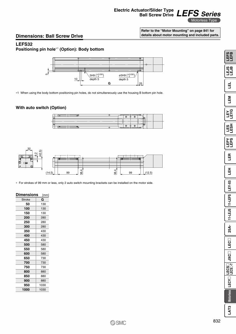
5
10
G 25
+0.03005H9 ( )
depth 5ø5H9 ( )depth 5
+0.0300
32
(42.
5)
8.2
(14.5) 99 38.4
38.4
99 (12.5)
Dimensions: Ball Screw DriveRefer to the “Motor Mounting” on page 841 for details about motor mounting and included parts.
LEFS32
Dimensions [mm]
Stroke G50 130
100 130
150 130
200 280
250 280
300 280
350 430
400 430
450 430
500 580
550 580
600 580
650 730
700 730
750 730
800 880
850 880
900 880
950 1030
1000 1030
∗1 When using the body bottom positioning pin holes, do not simultaneously use the housing B bottom pin hole.
Positioning pin hole∗1 (Option): Body bottom
With auto switch (Option)
∗ For strokes of 99 mm or less, only 2 auto switch mounting brackets can be installed on the motor side.
832
Electric Actuator/Slider TypeBall Screw Drive LEFS Series
Motorless Type
LE
FS
LE
FB
LE
LL
EJS
LE
JBL
EM
LE
YL
EY
GL
ES
LE
SH
LE
PY
LE
PS
LE
RL
EH
LEY-
X511
-LEF
S11
-LEJ
S25
A-
Moto
rless
LEC
Y�LE
CS
�LE
CS�-
TJX
C�
LE
C�
LA
T3
106
58
(170)
4 x M8 x 1.25thread depth 13
60
7
90
61
(68)
31
8
8M4 x 0.7thread depth 8(F.G. terminal)
13 (86)53
.8 68
A (Table traveling distance) 86 48 FFL
67.5
Motor
76
BD x 150 (= E) 60 15
150
7
6H9 ( )depth 7
6H9 ( )depth 6
n x ø6.6
4 x FA thread depth FB
Motor mating part:øFD, depth FE
45°
Mounting pitch: FC74
Motor flange
+0.0300
ø6H9 ( )depth 7
+0.0300
+0.0300
Body mountingreference plane(B dimension range)∗1
Applicable motor dimensionsø
FD
FC
FA(FC)FK
FEøF
J
Dimensions: Ball Screw Drive
LEFS40
Refer to the “Motor Mounting” on page 841 for details about motor mounting and included parts.
∗1 When mounting the actuator using the body mounting reference plane, set the height of the opposite surface or pin to be 3 mm or more. (Recommended height 5 mm)
Dimensions [mm]
Stroke L A B n D E150 389 156 328 4 — 150
200 439 206 378 6 2 300
250 489 256 428 6 2 300
300 539 306 478 6 2 300
350 589 356 528 8 3 450
400 639 406 578 8 3 450
450 689 456 628 8 3 450
500 739 506 678 10 4 600
550 789 556 728 10 4 600
600 839 606 778 10 4 600
650 889 656 828 12 5 750
700 939 706 878 12 5 750
750 989 756 928 12 5 750
800 1039 806 978 14 6 900
850 1089 856 1028 14 6 900
900 1139 906 1078 14 6 900
950 1189 956 1128 16 7 1050
1000 1239 1006 1178 16 7 1050
1100 1339 1106 1278 18 8 1200
1200 1439 1206 1378 18 8 1200
Motor Mounting, Applicable Motor Dimensions [mm]
Mounting type
FAFB FC FD FE
(Max.)FF FJ FKMounting
typeApplicable
motor
NZ M5 x 0.8 ø5.8 9 ø70 50 5 47.5 14 30 ±1
NY M4 x 0.7 ø4.5 8 ø70 50 5 47.5 14 30 ±1
NX M5 x 0.8 ø5.8 9 ø63 40∗1 4.5∗1 51 9 20 ±1
NW M5 x 0.8 ø5.8 9 ø70 50 5 48.8 9 25 ±1
NV M4 x 0.7 ø4.5 8 ø63 40∗1 4.5∗1 51 9 20 ±1
NU M5 x 0.8 ø5.8 9 ø70 50 5 48.8 11 23 ±1
NT M5 x 0.8 ø5.8 9 ø70 50 5 47.5 12 30 ±1
NM1 M4 x 0.7 ø4.5 8 m47.14 38.1∗1 4.5∗1 22 6.35∗2 20 ±1
NM2 M4 x 0.7 ø4.5 8 m50 36∗1 4.5∗1 41.4 10 24 ±1
∗1 Dimensions after mounting a ring spacer (Refer to page 841.)∗2 Shaft type: D-cut shaft
833
LEFS SeriesMotorless Type
A
7
11
G 70
+0.03006H9 ( )
depth 6ø6H9 ( )depth 6
+0.0300
(48)
8.2
38.5
(38.5) 99
43.9
43.9 99 (36.5)
Dimensions: Ball Screw DriveRefer to the “Motor Mounting” on page 841 for details about motor mounting and included parts.
LEFS40
∗1 When using the body bottom positioning pin holes, do not simultaneously use the housing B bottom pin hole.
Positioning pin hole∗1 (Option): Body bottom
With auto switch (Option)
Dimensions [mm]
Stroke G150 130
200 280
250 280
300 280
350 430
400 430
450 430
500 580
550 580
600 580
650 730
700 730
750 730
800 880
850 880
900 880
950 1030
1000 1030
1100 1180
1200 1180
834
Electric Actuator/Slider TypeBall Screw Drive LEFS Series
Motorless Type
LE
FS
LE
FB
LE
LL
EJS
LE
JBL
EM
LE
YL
EY
GL
ES
LE
SH
LE
PY
LE
PS
LE
RL
EH
LEY-
X511
-LEF
S11
-LEJ
S25
A-
Moto
rless
LEC
Y�LE
CS
�LE
CS�-
TJX
C�
LE
C�
LA
T3
3.5
6.5 M4 x 0.7
thread depth 8(F.G. terminal)
6
38.5 48
4
FF 18.5 (2.4)
106
38
Motor flange
Motor
3H9 (+0.025 +0 )
depth 3
4 x M5 x 0.8thread depth 8.5
Body mounting reference plane(B dimension range)∗1
(102)
64
45
50
(52) A (Table traveling distance)
L10 52 40.5
Motor side stroke end
2 x FAthread depth FB
FFFE
øF
D
�FL
FF
øF
D
�42
FC
2 x FACounterbore diameter FG, depth FH
n x ø4.5
120
D x 120 (= E)
BG
10
48
(48)
24
38
58
F
3H9 (+0.025 +0 )
depth 3
45°
Mounting pitch: FC
ø3H9 (+0.025 +0 )
depth 3
Applicable motor dimensions
FKFEø
FJ
øF
D
(FC) FA
FC
Dimensions: Ball Screw Drive
LEFS25R
Refer to the “Motor Mounting” on page 842 fordetails about motor mounting and included parts.
Dimensions [mm]
∗1 When mounting the actuator using the body mounting reference plane, set the height of the opposite surface or pin to be 3 mm or more. (Recommended height 5 mm)
Mounting type: NM1, NM2, NM3
Mounting type: NZ, NY, NX
Stroke L A B n D E G50 210.5 56 160 4 — — 20
100 260.5 106 210 4 — — 35
150 310.5 156 260 4 — — 35
200 360.5 206 310 6 2 240 35
250 410.5 256 360 6 2 240 35
300 460.5 306 410 8 3 360 35
350 510.5 356 460 8 3 360 35
400 560.5 406 510 8 3 360 35
450 610.5 456 560 10 4 480 35
500 660.5 506 610 10 4 480 35
550 710.5 556 660 12 5 600 35
600 760.5 606 710 12 5 600 35
650 810.5 656 760 12 5 600 35
700 860.5 706 810 14 6 720 35
750 910.5 756 860 14 6 720 35
800 960.5 806 910 16 7 840 35
Motor Mounting, Applicable Motor Dimensions [mm]
Mounting type
FAFB FC FD FE
(Max.)FF FG FH FJ FK FLMounting
typeApplicable
motor
NZ M4 x 0.7 ø4.5 7.5 ø46 30 3.7 11 — — 8 25 ±1 42
NY M3 x 0.5 ø3.4 5.5 ø45 30 5 11 — — 8 25 ±1 38
NX M4 x 0.7 ø4.5 7 ø46 30 3.7 8 — — 8 18 ±1 42
NM1 ø3.4 M3 — m31 28 — 8.5 7 3.5 5∗1 24 ±1 42
NM2 ø3.4 M3 — m31 28 — 8.5 7 3.5 6 20 ±1 42
NM3 ø3.4 M3 — m31 28 — 5.5 7 3.5 5∗1 20 ±1 42
∗1 Shaft type: D-cut shaft
835
LEFS SeriesMotorless Type
A
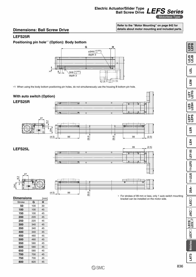
27
(34)
8.2
99(4.5)
29.9
29.9 99 (2.5)
27
8.2
(34)
29.999(4.5)
(2.5)99
5 8
G H
+0.02503H9 ( )
depth 3
+0.0250ø3H9 ( )
depth 3
Dimensions: Ball Screw DriveRefer to the “Motor Mounting” on page 842 fordetails about motor mounting and included parts.
LEFS25R
LEFS25R
LEFS25L
∗1 When using the body bottom positioning pin holes, do not simultaneously use the housing B bottom pin hole.
Positioning pin hole∗1 (Option): Body bottom
Dimensions [mm]
Stroke G H50 100 30
100 100 45
150 100 45
200 220 45
250 220 45
300 340 45
350 340 45
400 340 45
450 460 45
500 460 45
550 580 45
600 580 45
650 580 45
700 700 45
750 700 45
800 820 45
With auto switch (Option)
∗ For strokes of 99 mm or less, only 1 auto switch mounting bracket can be installed on the motor side.
836
Electric Actuator/Slider TypeBall Screw Drive LEFS Series
Motorless Type
LE
FS
LE
FB
LE
LL
EJS
LE
JBL
EM
LE
YL
EY
GL
ES
LE
SH
LE
PY
LE
PS
LE
RL
EH
LEY-
X511
-LEF
S11
-LEJ
S25
A-
Moto
rless
LEC
Y�LE
CS
�LE
CS�-
TJX
C�
LE
C�
LA
T3
46.8 63 3
6.5
7.5
M4 x 0.7thread depth 8(F.G. terminal)
5.5
ø5H9 (+0.030 +0 )
depth 8 (depth of counterbore 3)
5H9 (+0.030 +0 )
depth 8 (depth of counterbore 3)
5H9 (+0.030 +0 )
depth 5
Motor flange(2.4)22.5FFMotor
4 x M6 x 1thread depth 12.5 (depth of counterbore 3)
132.
5
44
(122)
70
42
Body mounting reference plane(B dimension range)∗1
60
CC
48
70
(63)
30
A (Table traveling distance) 62 55(62)10
LMotor side stroke end
2 x FAthread depth FB
øF
D
FEFF�FL
60
D x 150 (= E)
B
150
n x ø5.5
6
15
15
Mounting pitch: FC
45°
F
FF
øF
D
�FLFC
2 x FAthread depth FB
2 x (M4 x 0.7)(thread depth FH)
Applicable motor dimensions
FEFK
øF
JøF
D
(FC) FA
FC
Dimensions: Ball Screw Drive
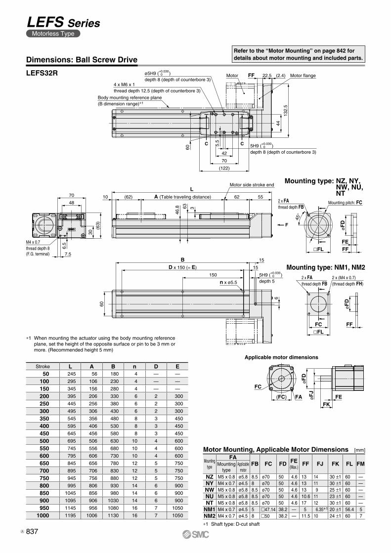
LEFS32R
Refer to the “Motor Mounting” on page 842 fordetails about motor mounting and included parts.
Dimensions [mm]
Mounting type: NM1, NM2
Mounting type: NZ, NY, NW, NU, NT
∗1 When mounting the actuator using the body mounting reference plane, set the height of the opposite surface or pin to be 3 mm or more. (Recommended height 5 mm)
Stroke L A B n D E50 245 56 180 4 — —
100 295 106 230 4 — —
150 345 156 280 4 — —
200 395 206 330 6 2 300
250 445 256 380 6 2 300
300 495 306 430 6 2 300
350 545 356 480 8 3 450
400 595 406 530 8 3 450
450 645 456 580 8 3 450
500 695 506 630 10 4 600
550 745 556 680 10 4 600
600 795 606 730 10 4 600
650 845 656 780 12 5 750
700 895 706 830 12 5 750
750 945 756 880 12 5 750
800 995 806 930 14 6 900
850 1045 856 980 14 6 900
900 1095 906 1030 14 6 900
950 1145 956 1080 16 7 1050
1000 1195 1006 1130 16 7 1050
Motor Mounting, Applicable Motor Dimensions [mm]
Mounting type
FAFB FC FD FE
(Max.)FF FJ FK FL FMMounting
typeApplicable
motorNZ M5 x 0.8 ø5.8 8.5 ø70 50 4.6 13 14 30 ±1 60 —NY M4 x 0.7 ø4.5 8 ø70 50 4.6 13 11 30 ±1 60 —NW M5 x 0.8 ø5.8 8.5 ø70 50 4.6 13 9 25 ±1 60 —NU M5 x 0.8 ø5.8 8.5 ø70 50 4.6 10.6 11 23 ±1 60 —NT M5 x 0.8 ø5.8 8.5 ø70 50 4.6 17 12 30 ±1 60 —
NM1 M4 x 0.7 ø4.5 5 m47.14 38.2 — 5 6.35∗1 20 ±1 56.4 5NM2 M4 x 0.7 ø4.5 8 m50 38.2 — 11.5 10 24 ±1 60 7
∗1 Shaft type: D-cut shaft
837
LEFS SeriesMotorless Type
A
5
10
G 25
ø5H9 ( )depth 5
+0.030ø5H9 ( )
depth 5
+0.030
32
8.2
(42.
5)
(14.5) 99
38.4
38.4 99 (12.5)
32
8.2
(42.
5)
(14.5) 99
38.4
99 (12.5)
Dimensions: Ball Screw DriveRefer to the “Motor Mounting” on page 842 fordetails about motor mounting and included parts.
LEFS32R
LEFS32R
LEFS32L
∗1 When using the body bottom positioning pin holes, do not simultaneously use the housing B bottom pin hole.
Positioning pin hole∗1 (Option): Body bottom
Stroke G50 130
100 130
150 130
200 280
250 280
300 280
350 430
400 430
450 430
500 580
Stroke G550 580
600 580
650 730
700 730
750 730
800 880
850 880
900 880
950 1030
1000 1030
Dimensions Dimensions[mm] [mm]
With auto switch (Option)
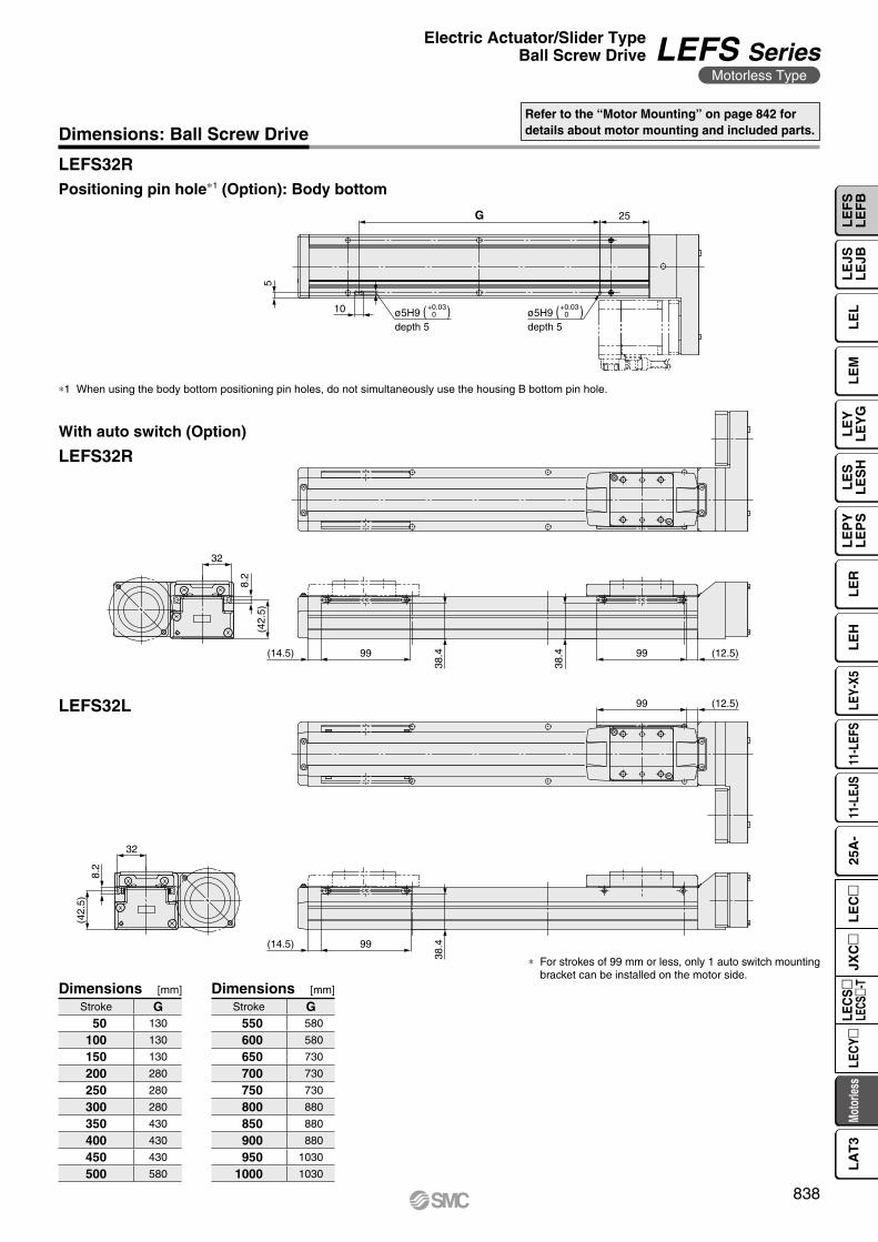
∗ For strokes of 99 mm or less, only 1 auto switch mounting bracket can be installed on the motor side.
838
Electric Actuator/Slider TypeBall Screw Drive LEFS Series
Motorless Type
LE
FS
LE
FB
LE
LL
EJS
LE
JBL
EM
LE
YL
EY
GL
ES
LE
SH
LE
PY
LE
PS
LE
RL
EH
LEY-
X511
-LEF
S11
-LEJ
S25
A-
Moto
rless
LEC
Y�LE
CS
�LE
CS�-
TJX
C�
LE
C�
LA
T3
F
153
58
(2.4)28FFMotor flange
Motorø6H9 (+0.030 +0 )
depth 7
4 x M8 x 1.25thread depth 13
Body mounting reference plane(B dimension range)∗1
(170)
106
60
7
74
6H9 (+0.030 +0 )
depth 7
M4 x 0.7thread depth 8(F.G. terminal)
8
8
68
31
61
90 13
Motor side stroke end
(86) A (Table traveling distance)
L86 62.4
6853.8
6H9 (+0.030 +0 )
depth 6n x ø6.67
BD x 150 (= E) 60
150
15
76
Mounting pitch: FC
4 x FAthread depth FB
�FL
øF
D
FEFF
45°
Applicable motor dimensions
øF
DøF
J
FKFEFA
FC
Dimensions: Ball Screw Drive
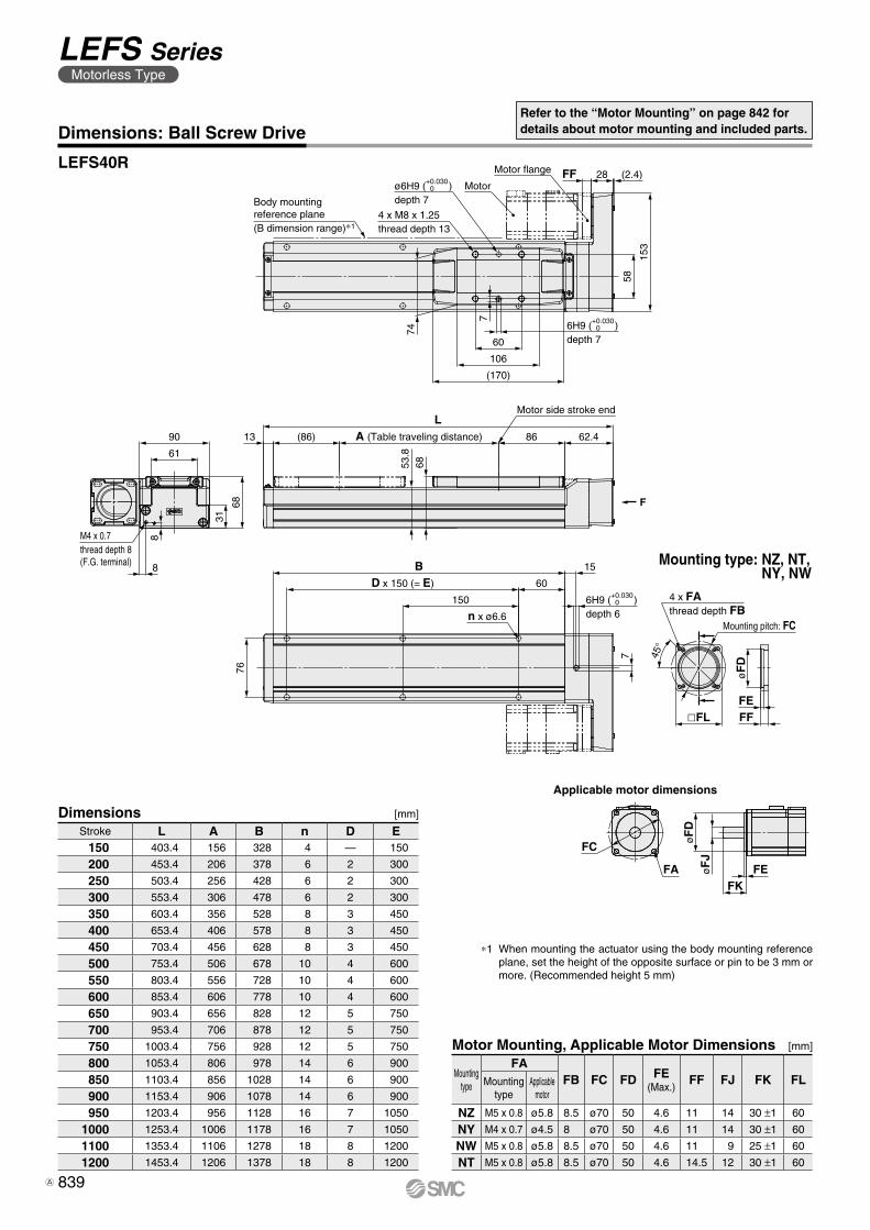
LEFS40R
Refer to the “Motor Mounting” on page 842 fordetails about motor mounting and included parts.
Dimensions [mm]
∗1 When mounting the actuator using the body mounting reference plane, set the height of the opposite surface or pin to be 3 mm or more. (Recommended height 5 mm)
Stroke L A B n D E150 403.4 156 328 4 — 150
200 453.4 206 378 6 2 300
250 503.4 256 428 6 2 300
300 553.4 306 478 6 2 300
350 603.4 356 528 8 3 450
400 653.4 406 578 8 3 450
450 703.4 456 628 8 3 450
500 753.4 506 678 10 4 600
550 803.4 556 728 10 4 600
600 853.4 606 778 10 4 600
650 903.4 656 828 12 5 750
700 953.4 706 878 12 5 750
750 1003.4 756 928 12 5 750
800 1053.4 806 978 14 6 900
850 1103.4 856 1028 14 6 900
900 1153.4 906 1078 14 6 900
950 1203.4 956 1128 16 7 1050
1000 1253.4 1006 1178 16 7 1050
1100 1353.4 1106 1278 18 8 1200
1200 1453.4 1206 1378 18 8 1200
Mounting type: NZ, NT, NY, NW
Motor Mounting, Applicable Motor Dimensions [mm]
Mounting type
FAFB FC FD FE
(Max.)FF FJ FK FLMounting
typeApplicable
motor
NZ M5 x 0.8 ø5.8 8.5 ø70 50 4.6 11 14 30 ±1 60
NY M4 x 0.7 ø4.5 8 ø70 50 4.6 11 14 30 ±1 60
NW M5 x 0.8 ø5.8 8.5 ø70 50 4.6 11 9 25 ±1 60
NT M5 x 0.8 ø5.8 8.5 ø70 50 4.6 14.5 12 30 ±1 60
839
LEFS SeriesMotorless Type
A
70G7 11 ø6H9 ( )
depth 6
+0.03006H9 ( )
depth 6
+0.0300
38.5
8.2
(48)
(38.5) 99
43.9
43.9 99 (36.5)
99 (36.5)
(48)
8.2
38.5
(38.5) 99
43.9
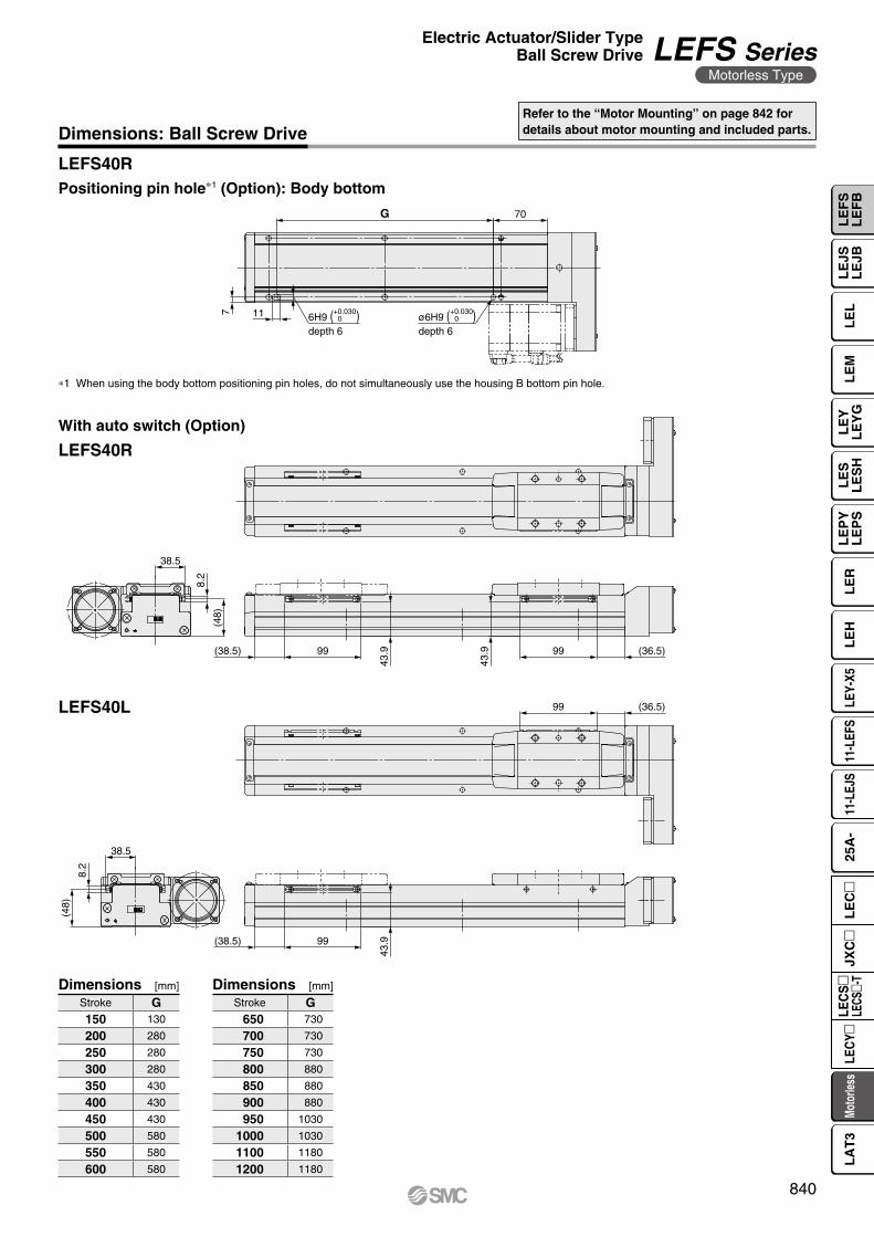
Dimensions: Ball Screw DriveRefer to the “Motor Mounting” on page 842 fordetails about motor mounting and included parts.
LEFS40R
LEFS40R
LEFS40L
∗1 When using the body bottom positioning pin holes, do not simultaneously use the housing B bottom pin hole.
Positioning pin hole∗1 (Option): Body bottom
Dimensions Dimensions[mm] [mm]
Stroke G150 130
200 280
250 280
300 280
350 430
400 430
450 430
500 580
550 580
600 580
Stroke G650 730
700 730
750 730
800 880
850 880
900 880
950 1030
1000 1030
1100 1180
1200 1180
With auto switch (Option)
840
Electric Actuator/Slider TypeBall Screw Drive LEFS Series
Motorless Type
LE
FS
LE
FB
LE
LL
EJS
LE
JBL
EM
LE
YL
EY
GL
ES
LE
SH
LE
PY
LE
PS
LE
RL
EH
LEY-
X511
-LEF
S11
-LEJ
S25
A-
Moto
rless
LEC
Y�LE
CS
�LE
CS�-
TJX
C�
LE
C�
LA
T3
Motor flange
[Included parts] Hexagon socket head cap screw/MM(Tightening torque: TT [N·m])
[Included parts] Motor side hub
øP
D
Mounting dimension: FPMotor mounting screw[Provided by the customer]
Motor[Provided by the customer]
[Included parts] Motor side hub
Motor flange
[Included parts] Hexagon socket head set screw/MM(Tightening torque: TT [N·m])
Motor mounting screw[Provided by the customer]
øP
D
Mounting dimension: FP
Motor[Provided by the customer]
Motor shaft
Hub
Hexagon socket head set screw
D-cut of the motor shaft
Motor flange
Motor side hub
Motor mounting screw
Motor
Body side hub[Built-in parts]
Spider[Built-in parts]
Motor
Motor mounting screw
[Included parts] Ring spacer
Body side hub[Built-in parts]
Motor flange
Spider[Built-in parts]
Match the convex part of the motor hub to the concavepart of the spider that is mounted on the body side hub.
Motor side hub
*1 For screw sizes, refer to the hub mounting dimensions.
*1 For screw sizes, refer to the hub mounting dimensions.
DescriptionQuantity
Mounting typeNZ NY NX NW NV NU NT NM1 NM2
Motor side hub 1 1 1 1 1 1 1 1 1Hexagon socket head cap screw/set screw
(to secure the hub)*1 1 1 1 1 1 1 1 1 1
Ring spacer — — 1 — 1 — — 1 1
DescriptionQuantity
Mounting typeNZ NY NX NM1 NM2
Motor side hub 1 1 1 1 1Hexagon socket head cap screw/set screw
(to secure the hub)*1 1 1 1 1 1
Hexagon socket head cap screw(to secure the motor flange)*1 — — — 2 2
Ring spacer — — — 1 1
Motor Mounting Diagram
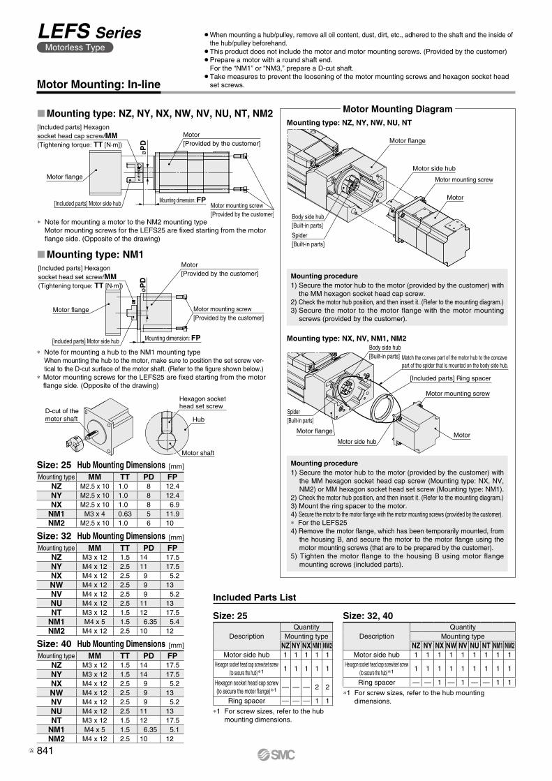
Motor Mounting: In-line
¡ When mounting a hub/pulley, remove all oil content, dust, dirt, etc., adhered to the shaft and the inside of the hub/pulley beforehand.
¡This product does not include the motor and motor mounting screws. (Provided by the customer)¡�Prepare a motor with a round shaft end.
For the “NM1” or “NM3,” prepare a D-cut shaft. ¡�Take measures to prevent the loosening of the motor mounting screws and hexagon socket head
set screws.
Mounting type: NX, NV, NM1, NM2
Mounting type: NM1
Mounting type: NZ, NY, NX, NW, NV, NU, NT, NM2Mounting type: NZ, NY, NW, NU, NT
* Note for mounting a hub to the NM1 mounting type When mounting the hub to the motor, make sure to position the set screw ver-tical to the D-cut surface of the motor shaft. (Refer to the figure shown below.)
* Motor mounting screws for the LEFS25 are fixed starting from the motor flange side. (Opposite of the drawing)
Included Parts List
[mm]
Mounting type MM TT PD FPNZ M2.5 x 10 1.0 8 12.4NY M2.5 x 10 1.0 8 12.4NX M2.5 x 10 1.0 8 6.9
NM1 M3 x 4 0.63 5 11.9NM2 M2.5 x 10 1.0 6 10
Size: 25 Hub Mounting Dimensions
[mm]
Mounting type MM TT PD FPNZ M3 x 12 1.5 14 17.5NY M4 x 12 2.5 11 17.5NX M4 x 12 2.5 9 5.2NW M4 x 12 2.5 9 13NV M4 x 12 2.5 9 5.2NU M4 x 12 2.5 11 13NT M3 x 12 1.5 12 17.5
NM1 M4 x 5 1.5 6.35 5.4NM2 M4 x 12 2.5 10 12
Size: 32 Hub Mounting Dimensions
[mm]
Mounting type MM TT PD FPNZ M3 x 12 1.5 14 17.5NY M3 x 12 1.5 14 17.5NX M4 x 12 2.5 9 5.2NW M4 x 12 2.5 9 13NV M4 x 12 2.5 9 5.2NU M4 x 12 2.5 11 13NT M3 x 12 1.5 12 17.5
NM1 M4 x 5 1.5 6.35 5.1NM2 M4 x 12 2.5 10 12
Size: 40 Hub Mounting Dimensions
Size: 25 Size: 32, 40
Mounting procedure1) Secure the motor hub to the motor (provided by the customer) with
the MM hexagon socket head cap screw.2) Check the motor hub position, and then insert it. (Refer to the mounting diagram.)3) Secure the motor to the motor flange with the motor mounting
screws (provided by the customer).
Mounting procedure1) Secure the motor hub to the motor (provided by the customer) with
the MM hexagon socket head cap screw (Mounting type: NX, NV, NM2) or MM hexagon socket head set screw (Mounting type: NM1).
2) Check the motor hub position, and then insert it. (Refer to the mounting diagram.)3) Mount the ring spacer to the motor.4) Secure the motor to the motor flange with the motor mounting screws (provided by the customer).* For the LEFS254) Remove the motor flange, which has been temporarily mounted, from
the housing B, and secure the motor to the motor flange using the motor mounting screws (that are to be prepared by the customer).
5) Tighten the motor flange to the housing B using motor flange mounting screws (included parts).
* Note for mounting a motor to the NM2 mounting type Motor mounting screws for the LEFS25 are fixed starting from the motor flange side. (Opposite of the drawing)
841
LEFS SeriesMotorless Type
A
øP
D Mounting dimension: FP
[Included parts] Timing belt(Belt tension/tensile force: BT [N])
[Included parts] Cover plate
[Included parts]Round head combination screw/M3 x 6(Tightening torque: 0.63 [N·m])
[Included parts] Hexagon socket head cap screw(Tightening torque: 0.63 [N·m])
[Included parts] Motor flange
[Included parts] Motor side pulley[Included parts] Hexagon socket head cap screw/MM(Tightening torque: TT [N·m])
Motor[Provided by the customer]
[Included parts] Return plate
[Included parts] Timing belt(Belt tension/tensile force: BT [N])
[Included parts] Cover plate
[Included parts]Round head combination screw/M3 x 6(Tightening torque: 0.63 [N·m])
[Included parts] Hexagon socket head cap screw(Tightening torque: 0.63 [N·m])
[Included parts] Motor flange
[Included parts] Hexagon socket head set screw/MM(Tightening torque: TT [N·m])
Motor[Provided by the customer]
øP
D
Mounting dimension: FP
[Included parts] Motor side pulley
[Included parts] Return plate
Hexagon sockethead set screw
Pulley
Motor shaft
D-cut of the motor shaft
Motor mounting screw[Provided by the customer]
Motor mounting screw[Provided by the customer]
Motor flange
Motor side pulley
Cover plateTiming belt
Body side pulley
Return plate
* Note for mounting a motor to the NM2 mounting type Motor mounting screws for the LEFS25 are fixed starting from the motor flange side. (Opposite of the drawing)
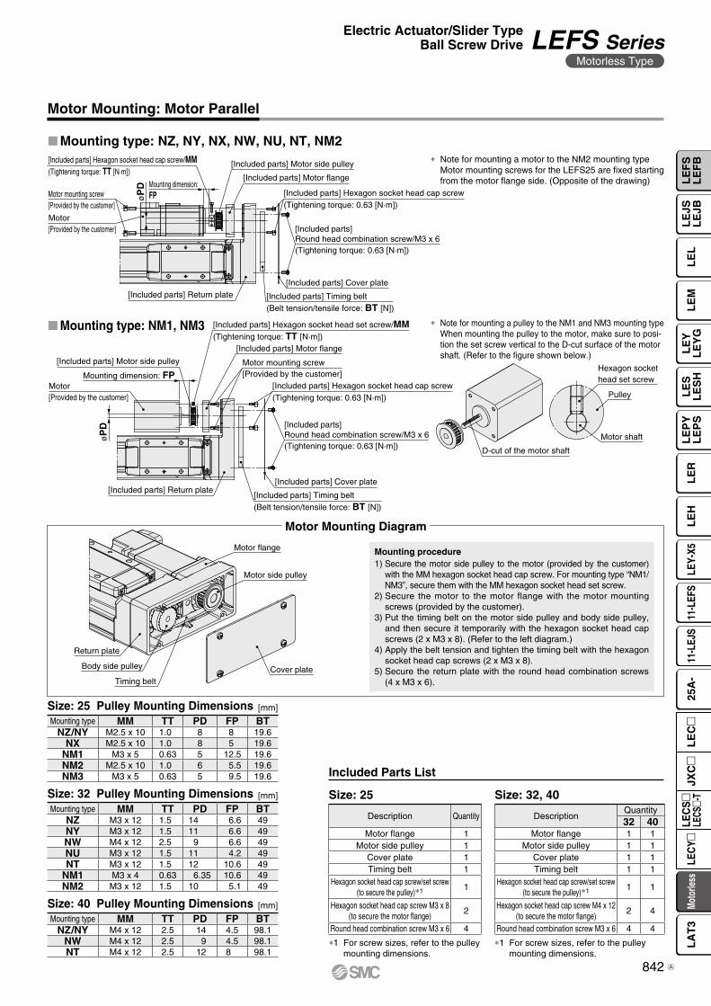
Motor Mounting: Motor Parallel
*1 For screw sizes, refer to the pulley mounting dimensions.
*1 For screw sizes, refer to the pulley mounting dimensions.
Description Quantity
Motor flange 1Motor side pulley 1
Cover plate 1Timing belt 1
Hexagon socket head cap screw/set screw (to secure the pulley)*1 1
Hexagon socket head cap screw M3 x 8(to secure the motor flange)
2
Round head combination screw M3 x 6 4
DescriptionQuantity32 40
Motor flange 1 1Motor side pulley 1 1
Cover plate 1 1Timing belt 1 1
Hexagon socket head cap screw/set screw(to secure the pulley)*1 1 1
Hexagon socket head cap screw M4 x 12(to secure the motor flange)
2 4
Round head combination screw M3 x 6 4 4
[mm]
Mounting type MM TT PD FP BTNZ/NY M2.5 x 10 1.0 8 8 19.6
NX M2.5 x 10 1.0 8 5 19.6NM1 M3 x 5 0.63 5 12.5 19.6NM2 M2.5 x 10 1.0 6 5.5 19.6NM3 M3 x 5 0.63 5 9.5 19.6
�Mounting type: NM1, NM3
Mounting type: NZ, NY, NX, NW, NU, NT, NM2
* Note for mounting a pulley to the NM1 and NM3 mounting type When mounting the pulley to the motor, make sure to posi-tion the set screw vertical to the D-cut surface of the motor shaft. (Refer to the figure shown below.)
Mounting procedure1) Secure the motor side pulley to the motor (provided by the customer)
with the MM hexagon socket head cap screw. For mounting type “NM1/NM3”, secure them with the MM hexagon socket head set screw.
2) Secure the motor to the motor flange with the motor mounting screws (provided by the customer).
3) Put the timing belt on the motor side pulley and body side pulley, and then secure it temporarily with the hexagon socket head cap screws (2 x M3 x 8). (Refer to the left diagram.)
4) Apply the belt tension and tighten the timing belt with the hexagon socket head cap screws (2 x M3 x 8).
5) Secure the return plate with the round head combination screws (4 x M3 x 6).
Motor Mounting Diagram
Included Parts List
Size: 25 Pulley Mounting Dimensions
[mm]
Mounting type MM TT PD FP BTNZ M3 x 12 1.5 14 6.6 49NY M3 x 12 1.5 11 6.6 49NW M4 x 12 2.5 9 6.6 49NU M3 x 12 1.5 11 4.2 49NT M3 x 12 1.5 12 10.6 49
NM1 M3 x 4 0.63 6.35 10.6 49NM2 M3 x 12 1.5 10 5.1 49
Size: 32 Pulley Mounting Dimensions
[mm]
Mounting type MM TT PD FP BTNZ/NY M4 x 12 2.5 14 4.5 98.1
NW M4 x 12 2.5 9 4.5 98.1NT M4 x 12 2.5 12 8 98.1
Size: 40 Pulley Mounting Dimensions
Size: 25 Size: 32, 40
842
Electric Actuator/Slider TypeBall Screw Drive LEFS Series
Motorless Type
LE
FS
LE
FB
LE
LL
EJS
LE
JBL
EM
LE
YL
EY
GL
ES
LE
SH
LE
PY
LE
PS
LE
RL
EH
LEY-
X511
-LEF
S11
-LEJ
S25
A-
Moto
rless
LEC
Y�LE
CS
�LE
CS�-
TJX
C�
LE
C�
LA
T3
A
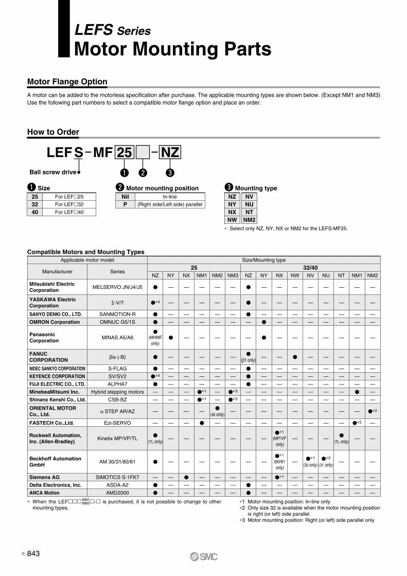
Motor Flange Option
NZMF 25SLEFBall screw drive
How to Order
LEFS Series
Motor Mounting Parts
q Size w Motor mounting position
q ew
25 For LEFl25
32 For LEFl32
40 For LEFl40
Nil In-line
P (Right side/Left side) parallel
* Select only NZ, NY, NX or NM2 for the LEFS-MF25.
e Mounting type
A motor can be added to the motorless specification after purchase. The applicable mounting types are shown below. (Except NM1 and NM3)Use the following part numbers to select a compatible motor flange option and place an order.
*1 Motor mounting position: In-line only*2 Only size 32 is available when the motor mounting position
is right (or left) side parallel.*3 Motor mounting position: Right (or left) side parallel only
* When the LEFmmm NM1NM3m-m is purchased, it is not possible to change to other
mounting types.
NZNYNXNW
NVNUNT
NM2
Compatible Motors and Mounting TypesApplicable motor model Size/Mounting type
Manufacturer Series25 32/40
NZ NY NX NM1 NM2 NM3 NZ NY NX NW NV NU NT NM1 NM2
Mitsubishi ElectricCorporation
MELSERVO JN/J4/J5 V — — — — — V — — — — — — — —
YASKAWA Electric Corporation Σ-V/7 V*4 — — — — — V — — — — — — — —
SANYO DENKI CO., LTD. SANMOTION R V — — — — — V — — — — — — — —
OMRON Corporation OMNUC G5/1S V — — — — — — V — — — — — — —
Panasonic Corporation
MINAS A5/A6V
(MHMFonly)
V — — — — — V — — — — — — —
FANUC CORPORATION βis (-B) V — — — — —
V(β1 only)
— — V — — — — —
NIDEC SANKYO CORPORATION S-FLAG V — — — — — V — — — — — — — —
KEYENCE CORPORATION SV/SV2 V*4 — — — — — V — — — — — — — —
FUJI ELECTRIC CO., LTD. ALPHA7 V — — — — — V — — — — — — — —
MinebeaMitsumi Inc. Hybrid stepping motors — — — V*1 — V*3 — — — — — — — V —
Shinano Kenshi Co., Ltd. CSB-BZ — — — V*1 — V*3 — — — — — — — — —
ORIENTAL MOTOR Co., Ltd. α STEP AR/AZ — — — —
V(46 only)
— — — — — — — — — V*2
FASTECH Co.,Ltd. Ezi-SERVO — — — V — — — — — — — — — V*2 —
Rockwell Automation, Inc. (Allen-Bradley)
Kinetix MP/VP/TLV
(TL only)— — — — — — —
V*1
(MP/VP only)
— — —V
(TL only)— —
Beckhoff AutomationGmbH
AM 30/31/80/81 V — — — — — — —V*1
(80/81 only)
—V*1
(30 only)V*2
(31 only)— — —
Siemens AG SIMOTICS S-1FK7 — — V — — — — — V*1 — — — — — —
Delta Electronics, Inc. ASDA-A2 V — — — — — V — — — — — — — —
ANCA Motion AMD2000 V — — — — — V — — — — — — — —
843A
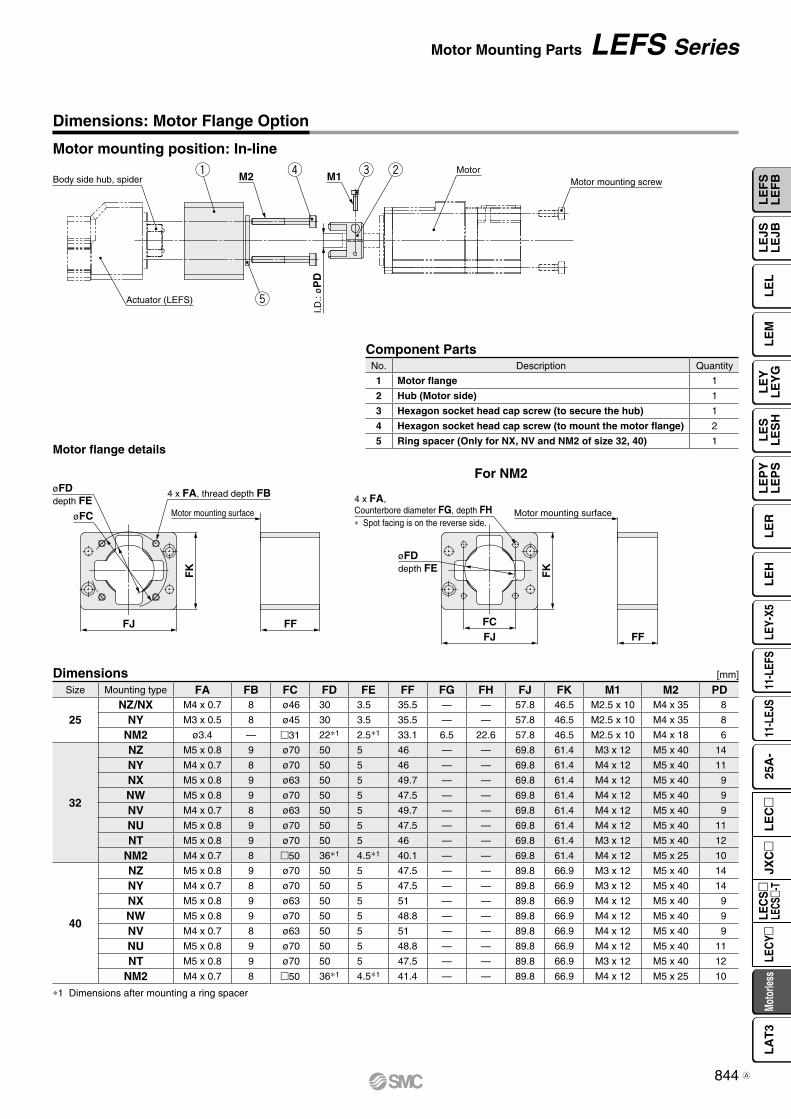
FFFJFC
4 x FA,Counterbore diameter FG, depth FH∗ Spot facing is on the reverse side.
øFDdepth FE F
K
Motor mounting surface
øFDdepth FE
øFC
4 x FA, thread depth FB
Motor mounting surface
FFFJ
FK
q werBody side hub, spider
Actuator (LEFS)
I.D.:
øP
D
M2 M1Motor
Motor mounting screw
t
Size Mounting type FA FB FC FD FE FF FG FH FJ FK M1 M2 PD
25NZ/NX M4 x 0.7 8 ø46 30 3.5 35.5 — — 57.8 46.5 M2.5 x 10 M4 x 35 8
NY M3 x 0.5 8 ø45 30 3.5 35.5 — — 57.8 46.5 M2.5 x 10 M4 x 35 8
NM2 ø3.4 — m31 22*1 2.5*1 33.1 6.5 22.6 57.8 46.5 M2.5 x 10 M4 x 18 6
32
NZ M5 x 0.8 9 ø70 50 5 46 — — 69.8 61.4 M3 x 12 M5 x 40 14
NY M4 x 0.7 8 ø70 50 5 46 — — 69.8 61.4 M4 x 12 M5 x 40 11
NX M5 x 0.8 9 ø63 50 5 49.7 — — 69.8 61.4 M4 x 12 M5 x 40 9
NW M5 x 0.8 9 ø70 50 5 47.5 — — 69.8 61.4 M4 x 12 M5 x 40 9
NV M4 x 0.7 8 ø63 50 5 49.7 — — 69.8 61.4 M4 x 12 M5 x 40 9
NU M5 x 0.8 9 ø70 50 5 47.5 — — 69.8 61.4 M4 x 12 M5 x 40 11
NT M5 x 0.8 9 ø70 50 5 46 — — 69.8 61.4 M3 x 12 M5 x 40 12
NM2 M4 x 0.7 8 m50 36*1 4.5*1 40.1 — — 69.8 61.4 M4 x 12 M5 x 25 10
40
NZ M5 x 0.8 9 ø70 50 5 47.5 — — 89.8 66.9 M3 x 12 M5 x 40 14
NY M4 x 0.7 8 ø70 50 5 47.5 — — 89.8 66.9 M3 x 12 M5 x 40 14
NX M5 x 0.8 9 ø63 50 5 51 — — 89.8 66.9 M4 x 12 M5 x 40 9
NW M5 x 0.8 9 ø70 50 5 48.8 — — 89.8 66.9 M4 x 12 M5 x 40 9
NV M4 x 0.7 8 ø63 50 5 51 — — 89.8 66.9 M4 x 12 M5 x 40 9
NU M5 x 0.8 9 ø70 50 5 48.8 — — 89.8 66.9 M4 x 12 M5 x 40 11
NT M5 x 0.8 9 ø70 50 5 47.5 — — 89.8 66.9 M3 x 12 M5 x 40 12
NM2 M4 x 0.7 8 m50 36*1 4.5*1 41.4 — — 89.8 66.9 M4 x 12 M5 x 25 10
For NM2
Motor flange details
Dimensions: Motor Flange Option
Dimensions [mm]
Component PartsNo. Description Quantity
1 Motor flange 1
2 Hub (Motor side) 1
3 Hexagon socket head cap screw (to secure the hub) 1
4 Hexagon socket head cap screw (to mount the motor flange) 2
5 Ring spacer (Only for NX, NV and NM2 of size 32, 40) 1
*1 Dimensions after mounting a ring spacer
Motor mounting position: In-line
844
Motor Mounting Parts LEFS Series
LE
FS
LE
FB
LE
LL
EJS
LE
JBL
EM
LE
YL
EY
GL
ES
LE
SH
LE
PY
LE
PS
LE
RL
EH
LEY-
X511
-LEF
S11
-LEJ
S25
A-
Moto
rless
LEC
Y�LE
CS
�LE
CS�-
TJX
C�
LE
C�
LA
T3
A
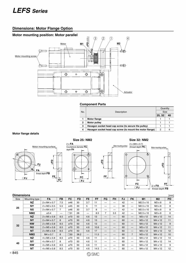
�FJ
FC
FAthread depth FB
Motor mounting surface
øF
D
FFFE
�FJFC
2 x FACounterbore diameter FG,depth FH
øF
D
FF
Motor mounting surface2 x (M4 x 0.7)(thread depth FK) Motor mounting surface
øF
D
FF2 x FAthread depth FB�FJ
FC
e w q r
Motor mounting screw
Motor M1
øP
D (
I.D.)
M2
Actuator
Size Mounting type FA FB FC FD FE FF FG FH FJ FK M1 M2 PD
25
NZ 2 x M4 x 0.7 7.5 ø46 30 3.7 11 — — 42 — M2.5 x 10 M3 x 8 8
NY 2 x M3 x 0.5 5.5 ø45 30 5 11 — — 38 — M2.5 x 10 M3 x 8 8
NX 2 x M4 x 0.7 7 ø46 30 3.7 8 — — 42 — M2.5 x 10 M3 x 8 8
NM2 ø3.4 — m31 28 — 8.5 7 3.5 42 — M2.5 x 10 M3 x 8 6
32
NZ 2 x M5 x 0.8 8.5 ø70 50 4.6 13 — — 60 — M3 x 12 M4 x 12 14
NY 2 x M4 x 0.7 8 ø70 50 4.6 13 — — 60 — M3 x 12 M4 x 12 11
NW 2 x M5 x 0.8 8.5 ø70 50 4.6 13 — — 60 — M4 x 12 M4 x 12 9
NU 2 x M5 x 0.8 8.5 ø70 50 4.6 10.6 — — 60 — M3 x 12 M4 x 12 11
NT 2 x M5 x 0.8 8.5 ø70 50 4.6 17 — — 60 — M3 x 12 M4 x 12 12
NM2 M4 x 0.7 8 m50 38.2 — 11.5 — — 60 7 M3 x 12 M4 x 12 10
40
NZ 4 x M5 x 0.8 8.5 ø70 50 4.6 11 — — 60 — M4 x 12 M4 x 12 14
NY 4 x M4 x 0.7 8 ø70 50 4.6 11 — — 60 — M4 x 12 M4 x 12 14
NW 4 x M5 x 0.8 8.5 ø70 50 4.6 11 — — 60 — M4 x 12 M4 x 12 9
NT 4 x M5 x 0.8 8.5 ø70 50 4.6 14.5 — — 60 — M4 x 12 M4 x 12 12
Size 25: NM2 Size 32: NM2
Dimensions: Motor Flange Option
Motor mounting position: Motor parallel
Dimensions [mm]
Motor flange details
Component Parts
No. Description
Quantity
Size
25, 32 401 Motor flange 1 1
2 Motor pulley 1 1
3 Hexagon socket head cap screw (to secure the pulley) 1 1
4 Hexagon socket head cap screw (to mount the motor flange) 2 4
845
LEFS Series
A
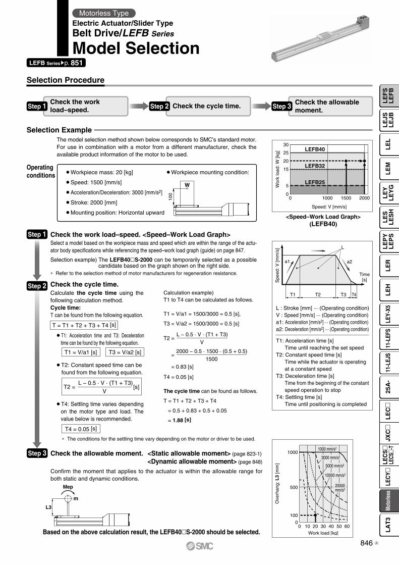
T1
a1 a2
L
Spe
ed: V
[mm
/s]
Time[s]
T2 T3 T4
L3
Mep
m
100
W
Speed: V [mm/s]
Wor
k lo
ad: W
[kg]
0 1000 200015000
15
5
20
25
30LEFB40
LEFB25
LEFB32
0
500
1000
0 10 20 30 40 50 60Work load [kg]
Ove
rhan
g: L
3 [m
m]
100
1000 mm/s2
3000 mm/s2
5000 mm/s2
10000 mm/s2
20000mm/s2
¡Workpiece mass: 20 [kg]
¡Speed: 1500 [mm/s]
¡Acceleration/Deceleration: 3000 [mm/s2]
¡Stroke: 2000 [mm]
¡Mounting position: Horizontal upward
¡Workpiece mounting condition:
Check the work load–speed. <Speed–Work Load Graph>Select a model based on the workpiece mass and speed which are within the range of the actu-ator body specifications while referencing the speed–work load graph (guide) on page 847.
Selection example) The LEFB40lS-2000 can be temporarily selected as a possible candidate based on the graph shown on the right side.
Check the cycle time.Calculate the cycle time using the following calculation method.Cycle time:T can be found from the following equation.
¡T4: Settling time varies depending on the motor type and load. The value below is recommended.
¡T2: Constant speed time can befound from the following equation.
¡T1: Acceleration time and T3: Deceleration time can be found by the following equation.
Based on the above calculation result, the LEFB40lS-2000 should be selected.
Calculation example)T1 to T4 can be calculated as follows.
T1 = V/a1 = 1500/3000 = 0.5 [s],
T3 = V/a2 = 1500/3000 = 0.5 [s]
T4 = 0.05 [s]
The cycle time can be found as follows.
T = T1 + T2 + T3 + T4
= 0.5 + 0.83 + 0.5 + 0.05
= 1.88 [s]
* The conditions for the settling time vary depending on the motor or driver to be used.
Selection Procedure
Selection Example
Step 1Check the work load–speed. Step 2 Check the cycle time. Step 3 Check the allowable
moment.
Operating conditions
Step 1
Step 2
T = T1 + T2 + T3 + T4 [s]
T1 = V/a1 [s] T3 = V/a2 [s]
T2 = [s] L − 0.5 · V · (T1 + T3)
V
T4 = 0.05 [s]
L : Stroke [mm] ··· (Operating condition)V : Speed [mm/s] ··· (Operating condition)a1: Acceleration [mm/s2] ··· (Operating condition)a2: Deceleration [mm/s2] ··· (Operating condition)
T1: Acceleration time [s]Time until reaching the set speed
T2: Constant speed time [s]Time while the actuator is operating at a constant speed
T3: Deceleration time [s]Time from the beginning of the constant speed operation to stop
T4: Settling time [s]Time until positioning is completed
T2 =
=
= 0.83 [s]
L − 0.5 · V · (T1 + T3)
V
2000 − 0.5 · 1500 · (0.5 + 0.5)
1500
* Refer to the selection method of motor manufacturers for regeneration resistance.
<Speed–Work Load Graph>(LEFB40)
LEFB Seriessp. 851
Motorless TypeElectric Actuator/Slider TypeBelt Drive/LEFB Series
Model Selection
The model selection method shown below corresponds to SMC’s standard motor.For use in combination with a motor from a different manufacturer, check the available product information of the motor to be used.
Step 3 Check the allowable moment. <Static allowable moment> (page 823-1)
<Dynamic allowable moment> (page 848)
Confirm the moment that applies to the actuator is within the allowable range for both static and dynamic conditions.
846
LE
FS
LE
FB
LE
LL
EJS
LE
JBL
EM
LE
YL
EY
GL
ES
LE
SH
LE
PY
LE
PS
LE
RL
EH
LEY-
X511
-LEF
S11
-LEJ
S25
A-
Moto
rless
LEC
Y�LE
CS
�LE
CS�-
TJX
C�
LE
C�
LA
T3
A
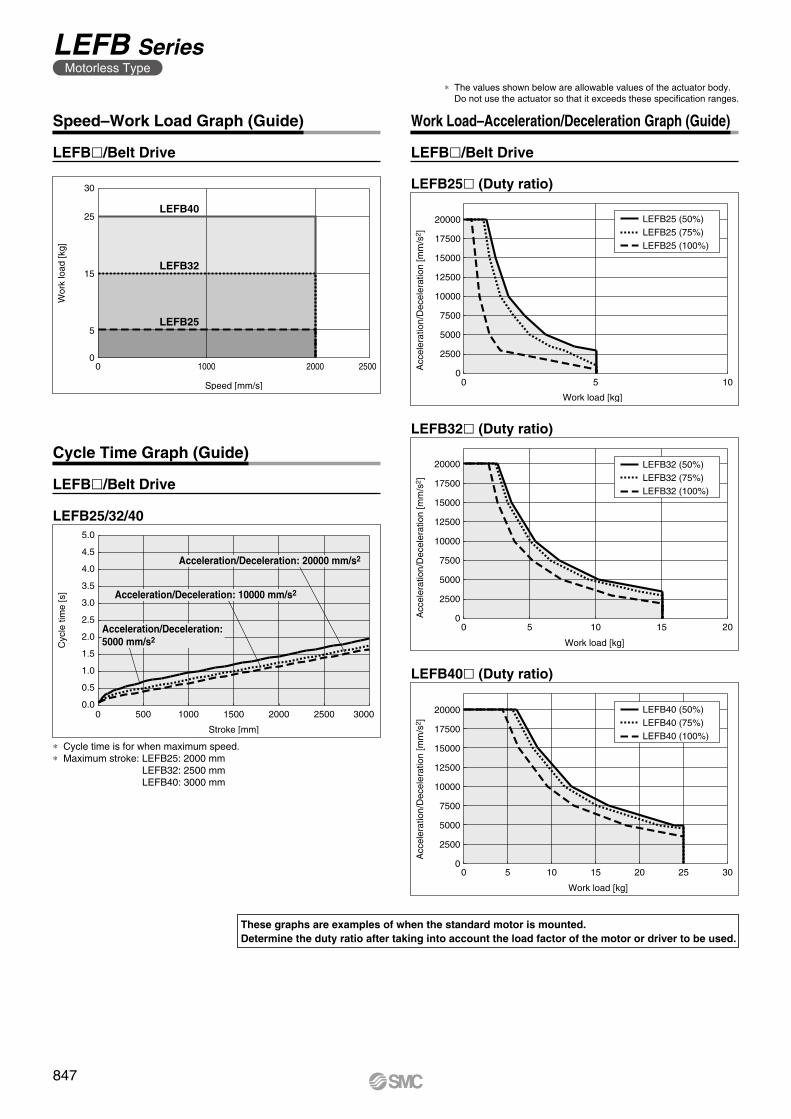
LEFB40
LEFB25
LEFB32
0 1000 2000 2500
Speed [mm/s]
0
5
15
25
30
Wor
k lo
ad [k
g]
0.0
0.5
1.0
1.5
2.0
2.5
3.0
3.5
4.0
4.5
5.0
Cyc
le ti
me
[s]
0 500 1000 1500 2000 2500 3000
Stroke [mm]
Acceleration/Deceleration: 10000 mm/s2
Acceleration/Deceleration: 20000 mm/s2
Acceleration/Deceleration: 5000 mm/s2
LEFB25 (50%)LEFB25 (75%)LEFB25 (100%)
Acc
eler
atio
n/D
ecel
erat
ion
[mm
/s2 ]
Work load [kg]
0 5 100
2500
5000
7500
10000
12500
15000
17500
20000
LEFB32 (50%)LEFB32 (75%)LEFB32 (100%)
2500
5000
7500
10000
12500
15000
17500
20000
Acc
eler
atio
n/D
ecel
erat
ion
[mm
/s2 ]
0 5 10 15 20
Work load [kg]
0
LEFB40 (50%)LEFB40 (75%)LEFB40 (100%)
Acc
eler
atio
n/D
ecel
erat
ion
[mm
/s2 ]
Work load [kg]
0
2500
5000
7500
10000
12500
15000
17500
20000
0 5 10 15 20 25 30
Speed–Work Load Graph (Guide) Work Load–Acceleration/Deceleration Graph (Guide)
LEFBl/Belt Drive
Cycle Time Graph (Guide)
LEFBl/Belt Drive
LEFBl/Belt Drive
LEFB32l (Duty ratio)
LEFB25l (Duty ratio)
LEFB40l (Duty ratio)
LEFB25/32/40
* The values shown below are allowable values of the actuator body. Do not use the actuator so that it exceeds these specification ranges.
These graphs are examples of when the standard motor is mounted.Determine the duty ratio after taking into account the load factor of the motor or driver to be used.
* Cycle time is for when maximum speed.* Maximum stroke: LEFB25: 2000 mm
LEFB32: 2500 mmLEFB40: 3000 mm
847
LEFB SeriesMotorless Type
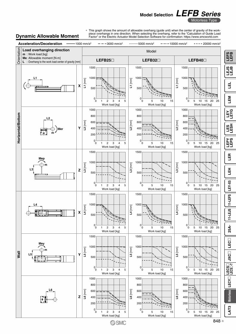
Work load [kg]
L1
[mm
]
Work load [kg]
L1
[mm
]
Work load [kg]
L1
[mm
]
Work load [kg]
L3
[mm
]
Work load [kg]
L3
[mm
]
Work load [kg]
L3
[mm
]
Work load [kg]
L4
[mm
]
Work load [kg]
L4
[mm
]
Work load [kg]
L4
[mm
]
Work load [kg]
L5
[mm
]
Work load [kg]
L5
[mm
]
Work load [kg]
L5
[mm
]
Work load [kg]
L2
[mm
]
Work load [kg]Work load [kg]
L2
[mm
]
L2
[mm
]
Work load [kg]
L6
[mm
]
Work load [kg]
L6
[mm
]
Work load [kg]
L6
[mm
]
0
200
400
600
800
1000
0
200
400
600
800
1000
0
200
400
600
800
1000
0
500
1000
1500
0
500
1000
1500
0
500
1000
1500
0 1 2 3 4 5
0 1 2 3 4 5
0 5 10 15
0 5 10 15
0 5 10 15 20 25
0 5 10 15 20 25
0
200
400
600
800
1000
0
200
400
600
800
1000
0
200
400
600
800
1000
0
500
1000
1500
0
500
1000
1500
0
500
1000
1500
0
500
1000
1500
0
500
1000
1500
0
500
1000
1500
0
500
1000
1500
0
500
1000
1500
0
500
1000
1500
0 1 2 3 4 5
0 1 2 3 4 5
0 1 2 3 4 5
0 5 10 15
0 5 10 15
0 5 10 15
0 5 10 15
0 5 10 15 20 25
0 5 10 15 20 25
0 5 10 15 20 25
0 5 10 15 20 250 1 2 3 4 5
L1
L3
Mep
m
L5
Mey
m
L4
Merm
L2
L6
Acceleration/Deceleration 1000 mm/s2 3000 mm/s2 5000 mm/s2 10000 mm/s2 20000 mm/s2
Dynamic Allowable Moment
Orie
ntat
ion Load overhanging direction
m : Work load [kg]Me: Allowable moment [N·m]L : Overhang to the work load center of gravity [mm]
Model
LEFB25l LEFB32l LEFB40l
Ho
rizo
nta
l/Bo
tto
m
X
Y
Z
Wal
l
X
Y
Z
* This graph shows the amount of allowable overhang (guide unit) when the center of gravity of the work-piece overhangs in one direction. When selecting the overhang, refer to the “Calculation of Guide Load Factor” or the Electric Actuator Model Selection Software for confirmation: https://www.smcworld.com
848
Model Selection LEFB SeriesMotorless Type
LE
FS
LE
FB
LE
LL
EJS
LE
JBL
EM
LE
YL
EY
GL
ES
LE
SH
LE
PY
LE
PS
LE
RL
EH
LEY-
X511
-LEF
S11
-LEJ
S25
A-
Moto
rless
LEC
Y�LE
CS
�LE
CS�-
TJX
C�
LE
C�
LA
T3
A
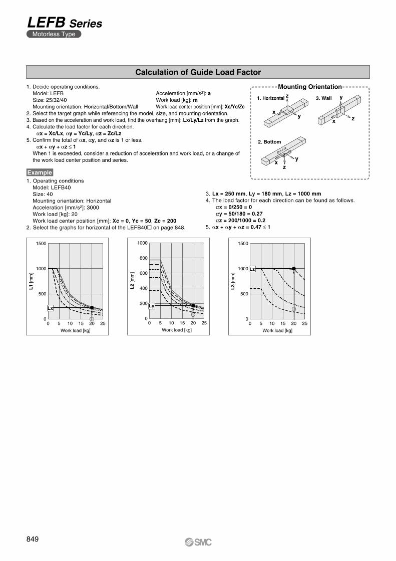
xy
z
x z
y
xy
z
0 5 10 15 20 250
500
1500
1000
Lx
L1
[mm
]
Work load [kg]
0 5 10 15 20 250
600
400
200
1000
800
L2
[mm
]
Work load [kg]
Ly
0 5 10 15 20 250
500
1500
1000
L3
[mm
]
Work load [kg]
Lz
Calculation of Guide Load Factor
Acceleration [mm/s2]: aWork load [kg]: mWork load center position [mm]: Xc/Yc/Zc
1. Decide operating conditions.Model: LEFBSize: 25/32/40Mounting orientation: Horizontal/Bottom/Wall
2. Select the target graph while referencing the model, size, and mounting orientation.3. Based on the acceleration and work load, find the overhang [mm]: Lx/Ly/Lz from the graph.4. Calculate the load factor for each direction.
αx = Xc/Lx, αy = Yc/Ly, αz = Zc/Lz5. Confirm the total of αx, αy, and αz is 1 or less.
αx + αy + αz ≤ 1When 1 is exceeded, consider a reduction of acceleration and work load, or a change of the work load center position and series.
Mounting Orientation
1. Horizontal 3. Wall
2. Bottom
Example1. Operating conditions
Model: LEFB40Size: 40Mounting orientation: HorizontalAcceleration [mm/s2]: 3000Work load [kg]: 20Work load center position [mm]: Xc = 0, Yc = 50, Zc = 200
2. Select the graphs for horizontal of the LEFB40m on page 848.
3. Lx = 250 mm, Ly = 180 mm, Lz = 1000 mm4. The load factor for each direction can be found as follows.
αx = 0/250 = 0αy = 50/180 = 0.27αz = 200/1000 = 0.2
5. αx + αy + αz = 0.47 ≤ 1
849
LEFB SeriesMotorless Type
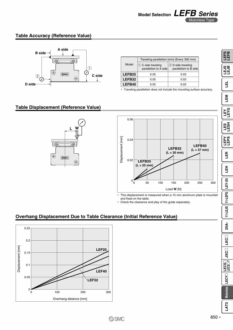
w
q
A side
C side
B side
D side
WL
LEFB25(L = 25 mm)
LEFB32(L = 30 mm)
LEFB40(L = 37 mm)
0.06
0.04
0.02
0
Dis
plac
emen
t [m
m]
0 10050 150 250200 300
Load W [N]
0
0.05
0.1
0.15
0.2
0.25
Dis
plac
emen
t [m
m]
0 100 200 300
Overhang distance [mm]
LEF25
LEF32
LEF40
Table Accuracy (Reference Value)
Table Displacement (Reference Value)
∗ Traveling parallelism does not include the mounting surface accuracy.
∗ This displacement is measured when a 15 mm aluminum plate is mounted and fixed on the table.
∗ Check the clearance and play of the guide separately.
Model
Traveling parallelism [mm] (Every 300 mm)
q C side travelingparallelism to A side
w D side travelingparallelism to B side
LEFB25 0.05 0.03
LEFB32 0.05 0.03
LEFB40 0.05 0.03
Overhang Displacement Due to Table Clearance (Initial Reference Value)
850
Model Selection LEFB SeriesMotorless Type
LE
FS
LE
FB
LE
LL
EJS
LE
JBL
EM
LE
YL
EY
GL
ES
LE
SH
LE
PY
LE
PS
LE
RL
EH
LEY-
X511
-LEF
S11
-LEJ
S25
A-
Moto
rless
LEC
Y�LE
CS
�LE
CS�-
TJX
C�
LE
C�
LA
T3
A
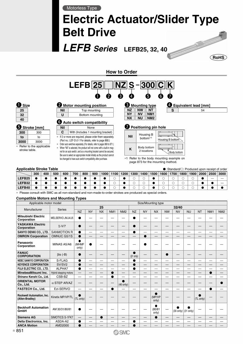
Compatible Motors and Mounting Types
How to Order
∗ Refer to the applicable stroke table.
t Stroke [mm]300 300
to to
3000 3000
w Motor mounting positionNil Top mounting
U Bottom mounting
r Equivalent lead [mm]S 54
q Size253240
V: Standard/v: Produced upon receipt of order
∗ Please consult with SMC as all non-standard and non-made-to-order strokes are produced as special orders.
Applicable Stroke Table300 400 500 600 700 800 900 1000 1100 1200 1300 1400 1500 1600 1700 1800 1900 2000 2500 3000
LEFB25 V V V V V V V V v V v v V v v v v V — —
LEFB32 V V V V V V V V v V v v V v v v v V V —
LEFB40 V V V V V V V V v V v v V v v v v V V V
Motorless Type
Electric Actuator/Slider TypeBelt DriveLEFB Series LEFB25, 32, 40
LEFB 25 300Sq w e r t
NZ Cy
Ku
u Positioning pin hole
Nil Housing B bottom∗1
Housing B bottom
K Body bottom2 locations Body bottom
∗1 Refer to the body mounting example on page 873 for the mounting method.
y Auto switch compatibilityNil None
C With (Includes 1 mounting bracket)
∗ If 2 or more are required, please order them separately. (Part no.: LEF-D-2-1 For details, refer to page 868.)
∗ Order auto switches separately. (For details, refer to pages 869 to 871.)∗ When “Nil” is selected, the product will not come with a built-in mag-
net for an auto switch, and so a mounting bracket cannot be secured. Be sure to select an appropriate model initially as the product cannot be changed to have auto switch compatibility after purchase.
e Mounting typeNZ NW NTNY NV NM1NX NU NM2
Applicable motor model Size/Mounting type
Manufacturer Series25 32/40
NZ NY NX NM1 NM2 NZ NY NX NW NV NU NT NM1 NM2
Mitsubishi ElectricCorporation MELSERVO JN/J4/J5 V — — — — V — — — — — — — —
YASKAWA Electric Corporation Σ-V/7 V — — — — V — — — — — — — —
SANYO DENKI CO., LTD. SANMOTION R V — — — — V — — — — — — — —OMRON Corporation OMNUC G5/1S V — — — — — V — — — — — — —
Panasonic Corporation MINAS A5/A6
V(MHMF
only)V — — — — V — — — — — — —
FANUC CORPORATION βis (-B) V — — — — V
(β1 only) — — V — — — — —
NIDEC SANKYO CORPORATION S-FLAG V — — — — V — — — — — — — —KEYENCE CORPORATION SV/SV2 V — — — — V — — — — — — — —FUJI ELECTRIC CO., LTD. ALPHA7 V — — — — V — — — — — — — —MinebeaMitsumi Inc. Hybrid stepping motors — — — V — — — — — — — — V —Shinano Kenshi Co., Ltd. CSB-BZ — — — V — — — — — — — — — —
ORIENTAL MOTOR Co., Ltd. α STEP AR/AZ — — — — V
(46 only) — — — — — — — — V
FASTECH Co., Ltd. Ezi-SERVO — — — V — — — — — — — — V —
Rockwell Automation, Inc.(Allen-Bradley) Kinetix MP/VP/TL V
(TL only) — — — — — —V
(MP/VPonly)
— — — V(TL only) — —
Beckhoff AutomationGmbH AM 30/31/80/81 V — — — — — —
V(80/81 only)
— V(30 only)
V(31 only) — — —
Siemens AG SIMOTICS S-1FK7 — — V — — — — V — — — — — —Delta Electronics, Inc. ASDA-A2 V — — — — V — — — — — — — —ANCA Motion AMD2000 V — — — — V — — — — — — — —
851A
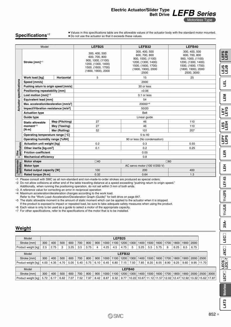
∗1 Please consult with SMC as all non-standard and non-made-to-order strokes are produced as special orders.∗2 Do not allow collisions at either end of the table traveling distance at a speed exceeding “pushing return to origin speed.”
Additionally, when running the positioning operation, do not set within 3 mm of both ends.∗3 A reference value for correcting an error in reciprocal operation∗4 Maximum acceleration/deceleration changes according to the work load.
Refer to the “Work Load–Acceleration/Deceleration Graph (Guide)” for belt drive on page 847.∗5 The static allowable moment is the amount of static moment which can be applied to the actuator when it is stopped.
If the product is exposed to impact or repeated load, be sure to take adequate safety measures when using the product.∗6 Each value is only to be used as a guide to select a motor of the appropriate capacity.∗7 For other specifications, refer to the specifications of the motor that is to be installed.
Specifications∗2¡Values in this specifications table are the allowable values of the actuator body with the standard motor mounted.¡Do not use the actuator so that it exceeds these values.
Model LEFB25 LEFB32 LEFB40
Act
uat
or
spec
ifica
tio
ns
Stroke [mm]∗1
300, 400, 500600, 700, 800
900, 1000, (1100)1200, (1300, 1400)1500, (1600, 1700)(1800, 1900), 2000
300, 400, 500600, 700, 800
900, 1000, (1100)1200, (1300, 1400)1500, (1600, 1700)(1800, 1900), 2000
2500
300, 400, 500600, 700, 800
900, 1000, (1100)1200, (1300, 1400)1500, (1600, 1700)(1800, 1900), 2000
2500, 3000
Work load [kg] Horizontal 5 15 25
Speed [mm/s] 2000
Pushing return to origin speed [mm/s] 30 or less
Positioning repeatability [mm] ±0.06
Lost motion [mm]∗3 0.1 or less
Equivalent lead [mm] 54
Max. acceleration/deceleration [mm/s2] 20000∗4
Impact/Vibration resistance [m/s2] 50/20
Actuation type Belt
Guide type Linear guide
Static allowable moment∗5
[N·m]
Mep (Pitching) 27 46 110
Mey (Yawing) 27 46 110
Mer (Rolling) 52 101 207
Operating temperature range [°C] 5 to 40
Operating humidity range [%RH] 90 or less (No condensation)
Othe
r sp
ecifi
catio
ns Actuation unit weight [kg] 0.2 0.3 0.55
Other inertia [kg·cm2] 0.1 0.2 0.25
Friction coefficient 0.05
Mechanical efficiency 0.8
Refer
ence
moto
rsp
ecific
ation
s Motor shape l40 l60
Motor type AC servo motor (100 V/200 V)
Rated output capacity [W] 100 200 400
Rated torque [N·m] 0.32 0.64 1.3
∗6
∗7
Weight
Model LEFB40Stroke [mm] 300 400 500 600 700 800 900 1000 1100 1200 1300 1400 1500 1600 1700 1800 1900 2000 2500 3000
Product weight [kg] 5.72 6.17 6.62 7.07 7.52 7.97 8.42 8.87 9.32 9.77 10.22 10.67 11.12 11.57 12.02 12.47 12.92 13.32 15.62 17.87
Model LEFB32Stroke [mm] 300 400 500 600 700 800 900 1000 1100 1200 1300 1400 1500 1600 1700 1800 1900 2000 2500
Product weight [kg] 4.00 4.35 4.70 5.05 5.40 5.75 6.10 6.45 6.80 7.15 7.50 7.85 8.20 8.55 8.90 9.25 9.60 9.95 11.70
Model LEFB25Stroke [mm] 300 400 500 600 700 800 900 1000 1100 1200 1300 1400 1500 1600 1700 1800 1900 2000
Product weight [kg] 2.5 2.75 3 3.25 3.5 3.75 4 4.25 4.5 4.75 5 5.25 5.5 5.75 6 6.25 6.5 6.75
852
Electric Actuator/Slider TypeBelt Drive LEFB Series
Motorless Type
LE
FS
LE
FB
LE
LL
EJS
LE
JBL
EM
LE
YL
EY
GL
ES
LE
SH
LE
PY
LE
PS
LE
RL
EH
LEY-
X511
-LEF
S11
-LEJ
S25
A-
Moto
rless
LEC
Y�LE
CS
�LE
CS�-
TJX
C�
LE
C�
LA
T3
B
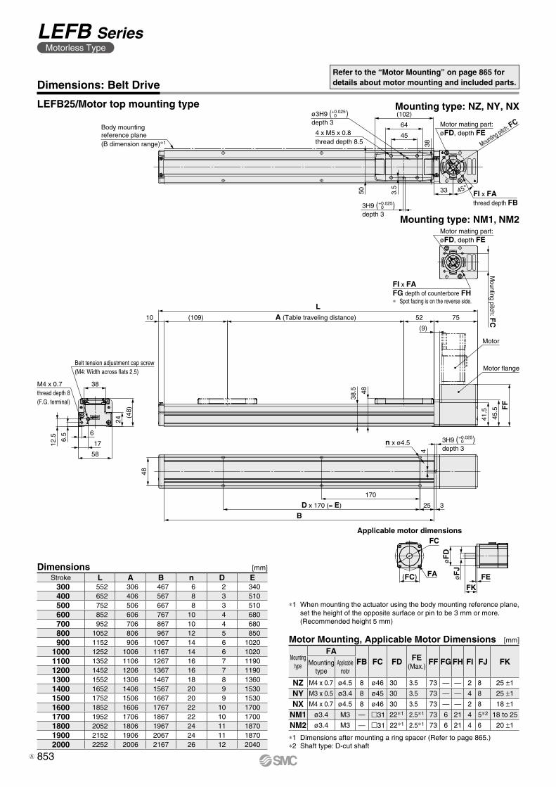
4 x M5 x 0.8thread depth 8.5
(102)
64
45Body mountingreference plane(B dimension range)∗1
33
38
45°FI x FAthread depth FB
3.5
50
Mounting pitch: FCMotor mating part:øFD, depth FE
ø3H9 ( )depth 3
+0.0250
3H9 ( )depth 3
+0.0250
M4 x 0.7thread depth 8(F.G. terminal)
Belt tension adjustment cap screw(M4: Width across flats 2.5)
38
(48)
24
58
17
6
6.5
12.5 3H9 ( )
depth 3
L(109)10 A (Table traveling distance) 52 75
(9)
FF
45.5
41.5
48
38.5
Motor
48
BD x 170 (= E)
170
25 3
n x ø4.5
4
Motor flange
FI x FAFG depth of counterbore FH∗ Spot facing is on the reverse side.
Motor mating part:øFD, depth FE
Mounting pitch: F
C
+0.0250
Applicable motor dimensions
FEøF
JøF
D
FC
FA(FC)FK
Dimensions: Belt DriveRefer to the “Motor Mounting” on page 865 for details about motor mounting and included parts.
Mounting type: NM1, NM2
Mounting type: NZ, NY, NXLEFB25/Motor top mounting type
Dimensions [mm]Stroke L A B n D E 300 552 306 467 6 2 340 400 652 406 567 8 3 510 500 752 506 667 8 3 510 600 852 606 767 10 4 680 700 952 706 867 10 4 680 800 1052 806 967 12 5 850 900 1152 906 1067 14 6 10201000 1252 1006 1167 14 6 10201100 1352 1106 1267 16 7 11901200 1452 1206 1367 16 7 11901300 1552 1306 1467 18 8 13601400 1652 1406 1567 20 9 15301500 1752 1506 1667 20 9 15301600 1852 1606 1767 22 10 17001700 1952 1706 1867 22 10 17001800 2052 1806 1967 24 11 18701900 2152 1906 2067 24 11 18702000 2252 2006 2167 26 12 2040
Motor Mounting, Applicable Motor Dimensions [mm]
Mounting type
FAFB FC FD FE
(Max.)FF FG FH FI FJ FKMounting
typeApplicable
motor
NZ M4 x 0.7 ø4.5 8 ø46 30 3.5 73 — — 2 8 25 ±1
NY M3 x 0.5 ø3.4 8 ø45 30 3.5 73 — — 4 8 25 ±1
NX M4 x 0.7 ø4.5 8 ø46 30 3.5 73 — — 2 8 18 ±1
NM1 ø3.4 M3 — m31 22∗1 2.5∗1 73 6 21 4 5∗2 18 to 25
NM2 ø3.4 M3 — m31 22∗1 2.5∗1 73 6 21 4 6 20 ±1
∗1 Dimensions after mounting a ring spacer (Refer to page 865.)∗2 Shaft type: D-cut shaft
∗1 When mounting the actuator using the body mounting reference plane, set the height of the opposite surface or pin to be 3 mm or more. (Recommended height 5 mm)
853
LEFB SeriesMotorless Type
A
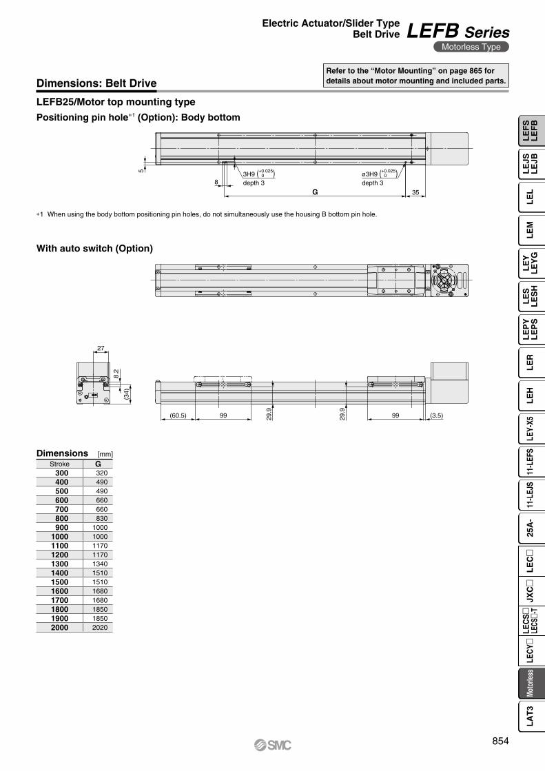
5
8
G 35
3H9 ( )depth 3
ø3H9 ( )depth 3
+0.0250
+0.0250
27
8.2
(34)
(60.5) 99 29.9
(3.5)9929.9
Dimensions: Belt DriveRefer to the “Motor Mounting” on page 865 for details about motor mounting and included parts.
LEFB25/Motor top mounting type
∗1 When using the body bottom positioning pin holes, do not simultaneously use the housing B bottom pin hole.
Positioning pin hole∗1 (Option): Body bottom
Dimensions [mm]Stroke G 300 320 400 490 500 490 600 660 700 660 800 830 900 10001000 10001100 11701200 11701300 13401400 15101500 15101600 16801700 16801800 18501900 18502000 2020
With auto switch (Option)
854
Electric Actuator/Slider TypeBelt Drive LEFB Series
Motorless Type
LE
FS
LE
FB
LE
LL
EJS
LE
JBL
EM
LE
YL
EY
GL
ES
LE
SH
LE
PY
LE
PS
LE
RL
EH
LEY-
X511
-LEF
S11
-LEJ
S25
A-
Moto
rless
LEC
Y�LE
CS
�LE
CS�-
TJX
C�
LE
C�
LA
T3
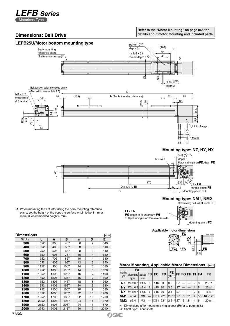
Body mountingreference plane(B dimension range)∗1
ø3H9 ( )depth 3
3H9 ( )depth 3
3H9 ( )depth 3
4 x M5 x 0.8thread depth 8.5
(102)
64
45
38
3.550
Belt tension adjustment cap screw(M4: Width across flats 2.5)
38
M4 x 0.7thread depth 8(F.G. terminal)
(48)
24
58
1712.5 6.5 6
LA (Table traveling distance) 52 75(109)10
38.5 48
(9)
45.5
FF
Motor flange
n x ø4.5
48
4
45°FI x FAthread depth FB
BD x 170 (= E)
170
25
33
3
Motor
Mounting pitch: FC
Motor mating part: øFD, depth FE
Mounting pitch: FC
Motor mating part: øFD, depth FE
+0.0250
+0.0250
+0.0250
FI x FAFG depth of counterbore FH∗ Spot facing is on the reverse side.
Applicable motor dimensions
FEFK
øF
JøF
D
FC
FA(FC)
LEFB25U/Motor bottom mounting type
Dimensions: Belt Drive
Mounting type: NM1, NM2
Mounting type: NZ, NY, NX
Refer to the “Motor Mounting” on page 865 for details about motor mounting and included parts.
Dimensions [mm]Stroke L A B n D E 300 552 306 467 6 2 340 400 652 406 567 8 3 510 500 752 506 667 8 3 510 600 852 606 767 10 4 680 700 952 706 867 10 4 680 800 1052 806 967 12 5 850 900 1152 906 1067 14 6 10201000 1252 1006 1167 14 6 10201100 1352 1106 1267 16 7 11901200 1452 1206 1367 16 7 11901300 1552 1306 1467 18 8 13601400 1652 1406 1567 20 9 15301500 1752 1506 1667 20 9 15301600 1852 1606 1767 22 10 17001700 1952 1706 1867 22 10 17001800 2052 1806 1967 24 11 18701900 2152 1906 2067 24 11 18702000 2252 2006 2167 26 12 2040
∗1 When mounting the actuator using the body mounting reference plane, set the height of the opposite surface or pin to be 3 mm or more. (Recommended height 5 mm)
Motor Mounting, Applicable Motor Dimensions [mm]
Mounting type
FAFB FC FD FE
(Max.)FF FG FH FI FJ FKMounting
typeApplicable
motor
NZ M4 x 0.7 ø4.5 8 ø46 30 3.5 27 — — 2 8 25 ±1
NY M3 x 0.5 ø3.4 8 ø45 30 3.5 27 — — 4 8 25 ±1
NX M4 x 0.7 ø4.5 8 ø46 30 3.5 27 — — 2 8 18 ±1
NM1 ø3.4 M3 — m31 22∗1 2.5∗1 27 6 21 4 5∗2 18 to 25
NM2 ø3.4 M3 — m31 22∗1 2.5∗1 27 6 21 4 6 20 ±1
∗1 Dimensions after mounting a ring spacer (Refer to page 865.)∗2 Shaft type: D-cut shaft
855
LEFB SeriesMotorless Type
A
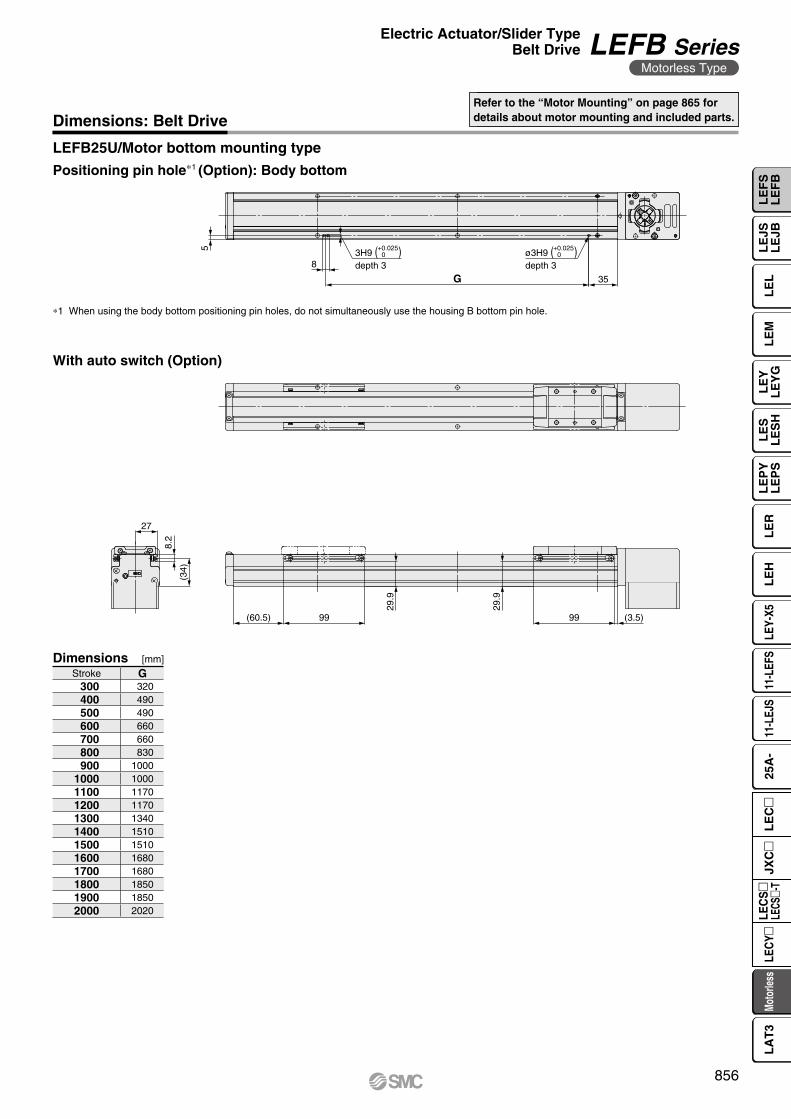
5
8
G 35
3H9 ( )depth 3
ø3H9 ( )depth 3
+0.0250
+0.0250
27
8.2
(34)
(60.5) 99
29.9
(3.5)99
29.9
LEFB25U/Motor bottom mounting type
Dimensions: Belt DriveRefer to the “Motor Mounting” on page 865 for details about motor mounting and included parts.
∗1 When using the body bottom positioning pin holes, do not simultaneously use the housing B bottom pin hole.
Positioning pin hole∗1 (Option): Body bottom
Dimensions [mm]Stroke G 300 320 400 490 500 490 600 660 700 660 800 830 900 10001000 10001100 11701200 11701300 13401400 15101500 15101600 16801700 16801800 18501900 18502000 2020
With auto switch (Option)
856
Electric Actuator/Slider TypeBelt Drive LEFB Series
Motorless Type
LE
FS
LE
FB
LE
LL
EJS
LE
JBL
EM
LE
YL
EY
GL
ES
LE
SH
LE
PY
LE
PS
LE
RL
EH
LEY-
X511
-LEF
S11
-LEJ
S25
A-
Moto
rless
LEC
Y�LE
CS
�LE
CS�-
TJX
C�
LE
C�
LA
T3
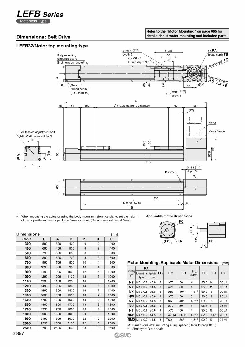
M4 x 0.7thread depth 8(F.G. terminal)
8
6Body mountingreference plane(B dimension range)∗1
4 x M6 x 1thread depth 9.5
(122)
70
42
44 45°
4 x FAthread depth FB
Mounting pitch: FC
Motor mating part:øFD, depth FE5.
5
4460
LA (Table traveling distance)(62)64(5)
55
62 96
(12)
Motor
FF
57.5
48
31.5
30
70
(60)
60
5H9 ( )depth 5n x ø5.5
200
D x 200 (= E)
B515
6
46.8 60
Motor flangeBelt tension adjustment bolt(M4: Width across flats 7)
ø5H9 ( )depth 5
+0.0300
5H9 ( )depth 5
+0.0300
+0.0300
Applicable motor dimensions
FEFK
øF
JøF
D
(FC) FA
FC
Dimensions: Belt DriveRefer to the “Motor Mounting” on page 865 for details about motor mounting and included parts.
LEFB32/Motor top mounting type
Dimensions [mm]
Stroke L A B n D E 300 590 306 430 6 2 400
400 690 406 530 6 2 400
500 790 506 630 8 3 600
600 890 606 730 8 3 600
700 990 706 830 10 4 800
800 1090 806 930 10 4 800
900 1190 906 1030 12 5 1000
1000 1290 1006 1130 12 5 1000
1100 1390 1106 1230 14 6 1200
1200 1490 1206 1330 14 6 1200
1300 1590 1306 1430 16 7 1400
1400 1690 1406 1530 16 7 1400
1500 1790 1506 1630 18 8 1600
1600 1890 1606 1730 18 8 1600
1700 1990 1706 1830 20 9 1800
1800 2090 1806 1930 20 9 1800
1900 2190 1906 2030 22 10 2000
2000 2290 2006 2130 22 10 2000
2500 2790 2506 2630 28 13 2600
∗1 When mounting the actuator using the body mounting reference plane, set the height of the opposite surface or pin to be 3 mm or more. (Recommended height 5 mm)
Motor Mounting, Applicable Motor Dimensions [mm]
Mounting type
FAFB FC FD FE
(Max.)FF FJ FKMounting
typeApplicable
motor
NZ M5 x 0.8 ø5.8 9 ø70 50 4 95.5 14 30 ±1
NY M4 x 0.7 ø4.5 8 ø70 50 4 95.5 11 30 ±1
NX M5 x 0.8 ø5.8 9 ø63 40∗1 4.5∗1 99.2 9 20 ±1
NW M5 x 0.8 ø5.8 9 ø70 50 5 96.5 9 25 ±1
NV M4 x 0.7 ø4.5 8 ø63 40∗1 4.5∗1 99.2 9 20 ±1
NU M5 x 0.8 ø5.8 9 ø70 50 5 96.5 11 23 ±1
NT M5 x 0.8 ø5.8 9 ø70 50 4 95.5 12 30 ±1
NM1 M4 x 0.7 ø4.5 8 m47.14 38.1∗1 4.5∗1 82.5 6.35∗2 20 ±1
NM2 M4 x 0.7 ø4.5 8 m50 36∗1 4.5∗1 90.0 10 24 ±1
∗1 Dimensions after mounting a ring spacer (Refer to page 865.)∗2 Shaft type: D-cut shaft
857
LEFB SeriesMotorless Type
A
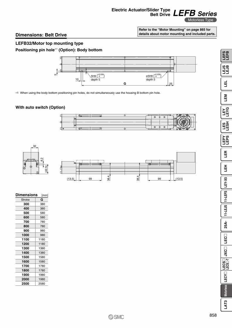
5
10
G 25
ø5H9 ( )depth 5
5H9 ( )depth 5
+0.0300
+0.0300
32
8.2
(42.
5)
(13.5)9938.4
38.4
99(13.5)
Dimensions: Belt DriveRefer to the “Motor Mounting” on page 865 for details about motor mounting and included parts.
LEFB32/Motor top mounting type
∗1 When using the body bottom positioning pin holes, do not simultaneously use the housing B bottom pin hole.
Positioning pin hole∗1 (Option): Body bottom
Dimensions [mm]
Stroke G 300 380
400 380
500 580
600 580
700 780
800 780
900 980
1000 980
1100 1180
1200 1180
1300 1380
1400 1380
1500 1580
1600 1580
1700 1780
1800 1780
1900 1980
2000 1980
2500 2580
With auto switch (Option)
858
Electric Actuator/Slider TypeBelt Drive LEFB Series
Motorless Type
LE
FS
LE
FB
LE
LL
EJS
LE
JBL
EM
LE
YL
EY
GL
ES
LE
SH
LE
PY
LE
PS
LE
RL
EH
LEY-
X511
-LEF
S11
-LEJ
S25
A-
Moto
rless
LEC
Y�LE
CS
�LE
CS�-
TJX
C�
LE
C�
LA
T3
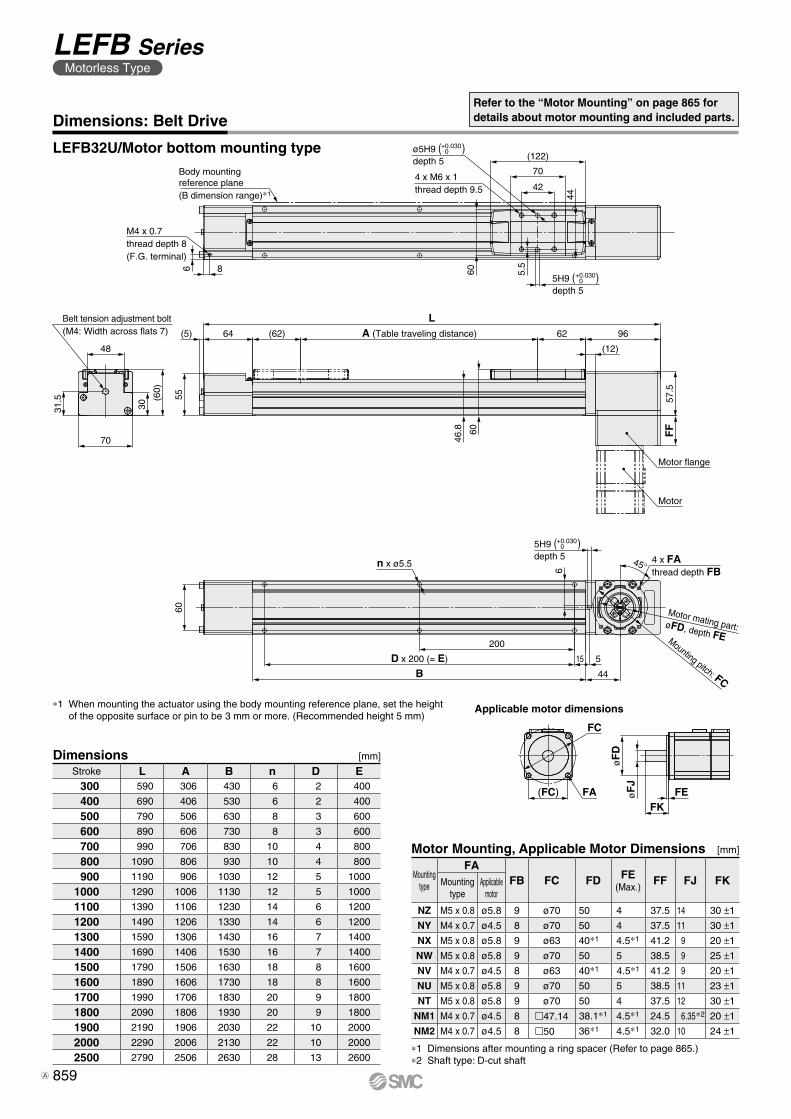
M4 x 0.7thread depth 8(F.G. terminal)
Body mountingreference plane(B dimension range)∗1
(122)
70
424 x M6 x 1thread depth 9.5
60
44
31.5
48
30
(60)
70
Belt tension adjustment bolt(M4: Width across flats 7)
55
LA (Table traveling distance)(62)64(5) 62 96
(12)
57.5
FF
Motor
46.8 60
60
n x ø5.5
D x 200 (= E)
B
200
44
6
15 5
4 x FAthread depth FB
45°
5.5
Motor mating part: øFD, depth FEMounting pitch: FC
Motor flange
ø5H9 ( )depth 5
+0.0300
5H9 ( )depth 5
+0.0300
5H9 ( )depth 5
+0.0300
86
Applicable motor dimensions
FEFK
øF
DøF
J
FC
(FC) FA
LEFB32U/Motor bottom mounting type
Dimensions: Belt DriveRefer to the “Motor Mounting” on page 865 for details about motor mounting and included parts.
Dimensions [mm]
Stroke L A B n D E 300 590 306 430 6 2 400
400 690 406 530 6 2 400
500 790 506 630 8 3 600
600 890 606 730 8 3 600
700 990 706 830 10 4 800
800 1090 806 930 10 4 800
900 1190 906 1030 12 5 1000
1000 1290 1006 1130 12 5 1000
1100 1390 1106 1230 14 6 1200
1200 1490 1206 1330 14 6 1200
1300 1590 1306 1430 16 7 1400
1400 1690 1406 1530 16 7 1400
1500 1790 1506 1630 18 8 1600
1600 1890 1606 1730 18 8 1600
1700 1990 1706 1830 20 9 1800
1800 2090 1806 1930 20 9 1800
1900 2190 1906 2030 22 10 2000
2000 2290 2006 2130 22 10 2000
2500 2790 2506 2630 28 13 2600
∗1 When mounting the actuator using the body mounting reference plane, set the height of the opposite surface or pin to be 3 mm or more. (Recommended height 5 mm)
Motor Mounting, Applicable Motor Dimensions [mm]
Mounting type
FAFB FC FD FE
(Max.)FF FJ FKMounting
typeApplicable
motor
NZ M5 x 0.8 ø5.8 9 ø70 50 4 37.5 14 30 ±1
NY M4 x 0.7 ø4.5 8 ø70 50 4 37.5 11 30 ±1
NX M5 x 0.8 ø5.8 9 ø63 40∗1 4.5∗1 41.2 9 20 ±1
NW M5 x 0.8 ø5.8 9 ø70 50 5 38.5 9 25 ±1
NV M4 x 0.7 ø4.5 8 ø63 40∗1 4.5∗1 41.2 9 20 ±1
NU M5 x 0.8 ø5.8 9 ø70 50 5 38.5 11 23 ±1
NT M5 x 0.8 ø5.8 9 ø70 50 4 37.5 12 30 ±1
NM1 M4 x 0.7 ø4.5 8 m47.14 38.1∗1 4.5∗1 24.5 6.35∗2 20 ±1
NM2 M4 x 0.7 ø4.5 8 m50 36∗1 4.5∗1 32.0 10 24 ±1
∗1 Dimensions after mounting a ring spacer (Refer to page 865.)∗2 Shaft type: D-cut shaft
859
LEFB SeriesMotorless Type
A
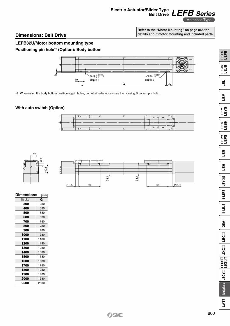
5
10
G 25
ø5H9 ( )depth 5
5H9 ( )depth 5
+0.0300
+0.0300
32
8.2
(42.
5)
(13.5)99
38.4
38.4
99(13.5)
LEFB32U/Motor bottom mounting type
Dimensions: Belt DriveRefer to the “Motor Mounting” on page 865 for details about motor mounting and included parts.
∗1 When using the body bottom positioning pin holes, do not simultaneously use the housing B bottom pin hole.
Positioning pin hole∗1 (Option): Body bottom
Dimensions [mm]
Stroke G 300 380
400 380
500 580
600 580
700 780
800 780
900 980
1000 980
1100 1180
1200 1180
1300 1380
1400 1380
1500 1580
1600 1580
1700 1780
1800 1780
1900 1980
2000 1980
2500 2580
With auto switch (Option)
860
Electric Actuator/Slider TypeBelt Drive LEFB Series
Motorless Type
LE
FS
LE
FB
LE
LL
EJS
LE
JBL
EM
LE
YL
EY
GL
ES
LE
SH
LE
PY
LE
PS
LE
RL
EH
LEY-
X511
-LEF
S11
-LEJ
S25
A-
Moto
rless
LEC
Y�LE
CS
�LE
CS�-
TJX
C�
LE
C�
LA
T3
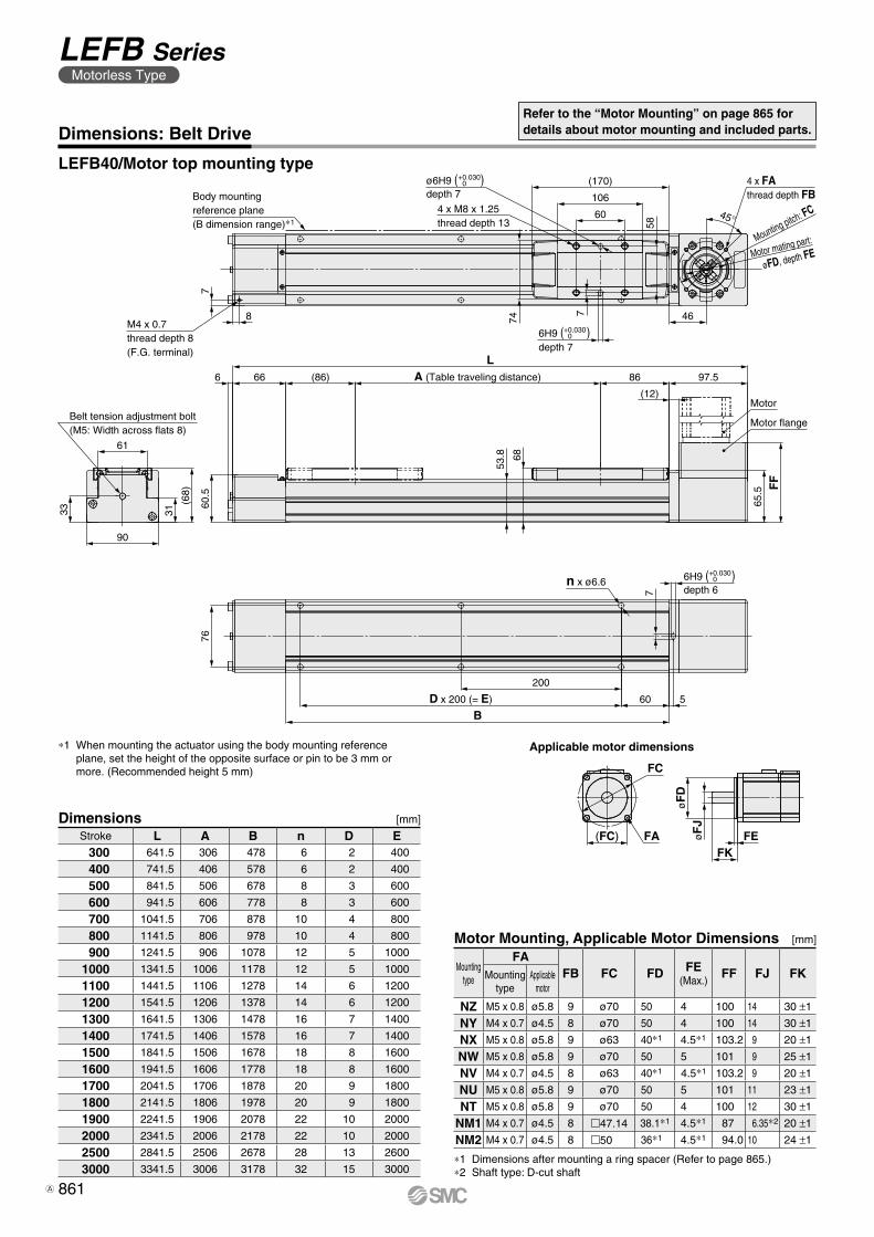
4 x FAthread depth FB
46
45°
Motor mating part:
øFD, depth FEMounting pitch: FC
(170)
106
60
ø6H9 ( )depth 7
4 x M8 x 1.25thread depth 13
Body mountingreference plane(B dimension range)∗1
M4 x 0.7thread depth 8(F.G. terminal)
7
8
58
7
74
LA (Table traveling distance)(86)666 86 97.5
(12)
60.5
65.5 F
F
61
33 31
(68)
90
Belt tension adjustment bolt(M5: Width across flats 8)
Motor
Motor flange
53.8 68
76
n x ø6.6
7
6H9 ( )depth 6
200
D x 200 (= E)
B60 5
+0.0300
6H9 ( )depth 7
+0.0300
+0.0300
Applicable motor dimensions
øF
DøF
J
FKFE(FC)
FC
FA
LEFB40/Motor top mounting type
Dimensions: Belt DriveRefer to the “Motor Mounting” on page 865 for details about motor mounting and included parts.
Dimensions [mm]
Stroke L A B n D E 300 641.5 306 478 6 2 400
400 741.5 406 578 6 2 400
500 841.5 506 678 8 3 600
600 941.5 606 778 8 3 600
700 1041.5 706 878 10 4 800
800 1141.5 806 978 10 4 800
900 1241.5 906 1078 12 5 1000
1000 1341.5 1006 1178 12 5 1000
1100 1441.5 1106 1278 14 6 1200
1200 1541.5 1206 1378 14 6 1200
1300 1641.5 1306 1478 16 7 1400
1400 1741.5 1406 1578 16 7 1400
1500 1841.5 1506 1678 18 8 1600
1600 1941.5 1606 1778 18 8 1600
1700 2041.5 1706 1878 20 9 1800
1800 2141.5 1806 1978 20 9 1800
1900 2241.5 1906 2078 22 10 2000
2000 2341.5 2006 2178 22 10 2000
2500 2841.5 2506 2678 28 13 2600
3000 3341.5 3006 3178 32 15 3000
∗1 When mounting the actuator using the body mounting reference plane, set the height of the opposite surface or pin to be 3 mm or more. (Recommended height 5 mm)
Motor Mounting, Applicable Motor Dimensions [mm]
Mounting type
FAFB FC FD FE
(Max.)FF FJ FKMounting
typeApplicable
motor
NZ M5 x 0.8 ø5.8 9 ø70 50 4 100 14 30 ±1
NY M4 x 0.7 ø4.5 8 ø70 50 4 100 14 30 ±1
NX M5 x 0.8 ø5.8 9 ø63 40∗1 4.5∗1 103.2 9 20 ±1
NW M5 x 0.8 ø5.8 9 ø70 50 5 101 9 25 ±1
NV M4 x 0.7 ø4.5 8 ø63 40∗1 4.5∗1 103.2 9 20 ±1
NU M5 x 0.8 ø5.8 9 ø70 50 5 101 11 23 ±1
NT M5 x 0.8 ø5.8 9 ø70 50 4 100 12 30 ±1
NM1 M4 x 0.7 ø4.5 8 m47.14 38.1∗1 4.5∗1 87 6.35∗2 20 ±1
NM2 M4 x 0.7 ø4.5 8 m50 36∗1 4.5∗1 94.0 10 24 ±1
∗1 Dimensions after mounting a ring spacer (Refer to page 865.)∗2 Shaft type: D-cut shaft
861
LEFB SeriesMotorless Type
A
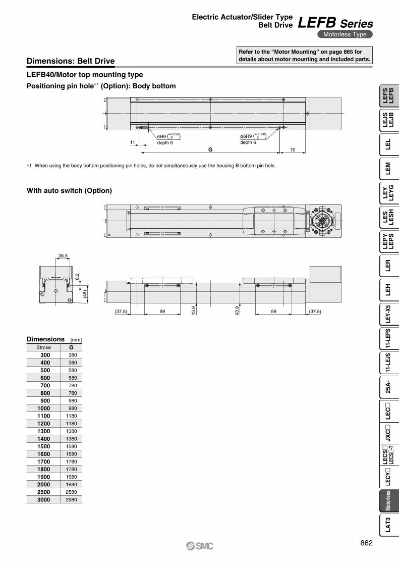
11
G 70
ø6H9 ( )depth 6
6H9 ( )depth 6
+0.0300
+0.0300
(48)
8.2
38.5
99 43.9
(37.5) 43.9
99 (37.5)
LEFB40/Motor top mounting type
Dimensions: Belt DriveRefer to the “Motor Mounting” on page 865 for details about motor mounting and included parts.
∗1 When using the body bottom positioning pin holes, do not simultaneously use the housing B bottom pin hole.
Positioning pin hole∗1 (Option): Body bottom
Dimensions [mm]
Stroke G 300 380
400 380
500 580
600 580
700 780
800 780
900 980
1000 980
1100 1180
1200 1180
1300 1380
1400 1380
1500 1580
1600 1580
1700 1780
1800 1780
1900 1980
2000 1980
2500 2580
3000 2980
With auto switch (Option)
862
Electric Actuator/Slider TypeBelt Drive LEFB Series
Motorless Type
LE
FS
LE
FB
LE
LL
EJS
LE
JBL
EM
LE
YL
EY
GL
ES
LE
SH
LE
PY
LE
PS
LE
RL
EH
LEY-
X511
-LEF
S11
-LEJ
S25
A-
Moto
rless
LEC
Y�LE
CS
�LE
CS�-
TJX
C�
LE
C�
LA
T3
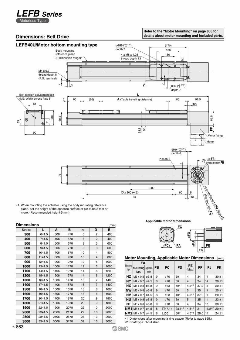
33
90
31
61
(68)
Belt tension adjustment bolt(M5: Width across flats 8)
76
BD x 200 (= E)
200
60
46
5
6H9 ( )depth 6
6H9 ( )depth 7
ø6H9 ( )depth 7
Motor m
ating part: øFD, depth FE
Mounting pitch: FC
45°
7
n x ø6.6 4 x FAthread depth FB
Motor
Motor flange
65.5
FF
60.5
A (Table traveling distance)66 (86)
L86 97.56
(12)
Body mountingreference plane(B dimension range)∗1
60
106
(170)
4 x M8 x 1.25thread depth 13
7 8
M4 x 0.7thread depth 8(F.G. terminal)
7
74
53.8 68
58
+0.0300
+0.0300
+0.0300
Applicable motor dimensions
FEFK
øF
JøF
D
FC
(FC) FA
LEFB40U/Motor bottom mounting type
Dimensions: Belt DriveRefer to the “Motor Mounting” on page 865 for details about motor mounting and included parts.
Dimensions [mm]
Stroke L A B n D E 300 641.5 306 478 6 2 400
400 741.5 406 578 6 2 400
500 841.5 506 678 8 3 600
600 941.5 606 778 8 3 600
700 1041.5 706 878 10 4 800
800 1141.5 806 978 10 4 800
900 1241.5 906 1078 12 5 1000
1000 1341.5 1006 1178 12 5 1000
1100 1441.5 1106 1278 14 6 1200
1200 1541.5 1206 1378 14 6 1200
1300 1641.5 1306 1478 16 7 1400
1400 1741.5 1406 1578 16 7 1400
1500 1841.5 1506 1678 18 8 1600
1600 1941.5 1606 1778 18 8 1600
1700 2041.5 1706 1878 20 9 1800
1800 2141.5 1806 1978 20 9 1800
1900 2241.5 1906 2078 22 10 2000
2000 2341.5 2006 2178 22 10 2000
2500 2841.5 2506 2678 28 13 2600
3000 3341.5 3006 3178 32 15 3000
∗1 When mounting the actuator using the body mounting reference plane, set the height of the opposite surface or pin to be 3 mm or more. (Recommended height 5 mm)
Motor Mounting, Applicable Motor Dimensions [mm]
Mounting type
FAFB FC FD FE
(Max.)FF FJ FKMounting
typeApplicable
motor
NZ M5 x 0.8 ø5.8 9 ø70 50 4 34 14 30 ±1
NY M4 x 0.7 ø4.5 8 ø70 50 4 34 14 30 ±1
NX M5 x 0.8 ø5.8 9 ø63 40∗1 4.5∗1 37.2 9 20 ±1
NW M5 x 0.8 ø5.8 9 ø70 50 5 35 9 25 ±1
NV M4 x 0.7 ø4.5 8 ø63 40∗1 4.5∗1 37.2 9 20 ±1
NU M5 x 0.8 ø5.8 9 ø70 50 5 35 11 23 ±1
NT M5 x 0.8 ø5.8 9 ø70 50 4 34 12 30 ±1
NM1 M4 x 0.7 ø4.5 8 m47.14 38.1∗1 4.5∗1 21 6.35∗2 20 ±1
NM2 M4 x 0.7 ø4.5 8 m50 36∗1 4.5∗1 28.0 10 24 ±1
∗1 Dimensions after mounting a ring spacer (Refer to page 865.)∗2 Shaft type: D-cut shaft
863
LEFB SeriesMotorless Type
A

11
G 70
ø6H9 ( )depth 6
6H9 ( )depth 6
+0.0300
+0.0300
(48)
8.2
38.5
99
43.9
(37.5)
43.9
99 (37.5)
LEFB40U/Motor bottom mounting type
Dimensions: Belt DriveRefer to the “Motor Mounting” on page 865 for details about motor mounting and included parts.
∗1 When using the body bottom positioning pin holes, do not simultaneously use the housing B bottom pin hole.
Positioning pin hole ∗1 (Option): Body bottom
Dimensions [mm]
Stroke G 300 380
400 380
500 580
600 580
700 780
800 780
900 980
1000 980
1100 1180
1200 1180
1300 1380
1400 1380
1500 1580
1600 1580
1700 1780
1800 1780
1900 1980
2000 1980
2500 2580
3000 2980
With auto switch (Option)
864
Electric Actuator/Slider TypeBelt Drive LEFB Series
Motorless Type
LE
FS
LE
FB
LE
LL
EJS
LE
JBL
EM
LE
YL
EY
GL
ES
LE
SH
LE
PY
LE
PS
LE
RL
EH
LEY-
X511
-LEF
S11
-LEJ
S25
A-
Moto
rless
LEC
Y�LE
CS
�LE
CS�-
TJX
C�
LE
C�
LA
T3
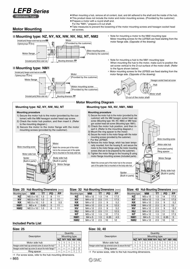
Motor[Provided by the customer]
Motor mounting screw[Provided by the customer]
Mounting dimension: FP
[Included parts] Hexagon socket head cap screw/MM(Tightening torque: TT [N·m])
Motor flange
[Included parts] Motor side hub
øP
D
[Included parts] Hexagon socket head set screw/MM(Tightening torque: TT [N·m])
Motor flange
Motor[Provided by the customer]
Motor mounting screw[Provided by the customer]
[Included parts] Motor side hub Mounting dimension: FP
øP
D
Hexagon socket head set screw
Hub
Motor shaft
D-cut of the motor shaft
Motor mounting screw
Motor side hub
Spider[Built-in parts]
Motor
Motor flange
Body side hub[Built-in parts]
Match the convex part of the motor hub to the concave part of the spider that is mounted on the body side hub.
Motor mounting screw
Motor side hub
[Included parts]Ring spacer
Motor flange
Body side hub[Built-in parts]Spider
[Built-in parts]
Match the convex part of the motor hub to the concave part of the spider that is mounted on the body side hub.
* Note for mounting a motor to the NM2 mounting type Motor mounting screws for the LEFB25 are fixed starting from the motor flange side. (Opposite of the drawing)
Size: 25 Size: 32, 40
*1 For screw sizes, refer to the hub mounting dimensions.*1 For screw sizes, refer to the hub mounting dimensions.
Mounting type MM TT PD FPNZ M3 x 12 1.5 14 17.5NY M4 x 12 2.5 11 17.5NX M4 x 12 2.5 9 5.2NW M4 x 12 2.5 9 12.5NV M4 x 12 2.5 9 5.2NU M4 x 12 2.5 11 12.5NT M3 x 12 1.5 12 17.5
NM1 M4 x 5 1.5 6.35 4.5NM2 M4 x 12 2.5 10 12
Mounting type MM TT PD FPNZ M2.5 x 10 1.0 8 11NY M2.5 x 10 1.0 8 11NX M2.5 x 10 1.0 8 5.5
NM1 M3 x 4 0.63 5 11NM2 M2.5 x 10 1.0 6 11
DescriptionQuantity
Mounting typeNZ NY NX NW NV NU NT NM1 NM2
Motor side hub 1 1 1 1 1 1 1 1 1Hexagon socket head cap screw/set screw (to secure the hub)*1 1 1 1 1 1 1 1 1 1
Ring spacer — — 1 — 1 — — 1 1
DescriptionQuantity
Mounting typeNZ NY NX NM1 NM2
Motor side hub 1 1 1 1 1Hexagon socket head cap screw/set screw (to secure the hub)*1 1 1 1 1 1Hexagon socket head cap screw (to secure the motor flange)*1 — — — 2 2
Ring spacer — — — 1 1
Mounting type MM TT PD FPNZ M3 x 12 1.5 14 17.5NY M3 x 12 1.5 14 17.5NX M4 x 12 2.5 9 5.2NW M4 x 12 2.5 9 13NV M4 x 12 2.5 9 5.2NU M4 x 12 2.5 11 13NT M3 x 12 1.5 12 17.5
NM1 M4 x 5 1.5 6.35 5NM2 M4 x 12 2.5 10 12
Motor Mounting
Included Parts List
Size: 25 Hub Mounting Dimensions [mm] Size: 32 Hub Mounting Dimensions [mm] Size: 40 Hub Mounting Dimensions [mm]
LMounting type: NM1
LMounting type: NZ, NY, NX, NW, NV, NU, NT, NM2
Mounting type: NZ, NY, NW, NU, NT Mounting type: NX, NV, NM1, NM2
* Note for mounting a hub to the NM1 mounting type When mounting the hub to the motor, make sure to position the set screw vertical to the D-cut surface of the motor shaft. (Refer to the figure shown below)
* Motor mounting screws for the LEFB25 are fixed starting from the motor flange side. (Opposite of the drawing)
Mounting procedure1) Secure the motor hub to the motor (provided by the
customer) with the MM hexagon socket head cap screw (Mounting type: NX, NV, NM2) or MM hexa-gon socket head set screw (Mounting type: NM1).
2) Check the motor hub position, and then in-sert it. (Refer to the mounting diagram.)
3) Mount the ring spacer to the motor.4) Secure the motor to the motor flange with the motor
mounting screws (provided by the customer).* For the LEFB254) Remove the motor flange, which has been tempo-
rarily mounted, from the housing B, and secure the motor to the motor flange using the motor mounting screws (that are to be prepared by the customer).
5) Tighten the motor flange to the housing B using motor flange mounting screws (included parts).
Mounting procedure1) Secure the motor hub to the motor (provided by the cus-
tomer) with the MM hexagon socket head cap screw.2) Check the motor hub position, and then insert it. (Refer
to the mounting diagram.)3) Secure the motor to the motor flange with the motor
mounting screws (provided by the customer).
Motor Mounting Diagram
¡When mounting a hub, remove all oil content, dust, and dirt adhered to the shaft and the inside of the hub.¡This product does not include the motor and motor mounting screws. (Provided by the customer)¡Prepare a motor with a round shaft end.
For the “NM1,” prepare a D-cut shaft.¡Take measures to prevent the loosening of the motor mounting screws and hexagon socket head
set screws.
865
LEFB SeriesMotorless Type
A
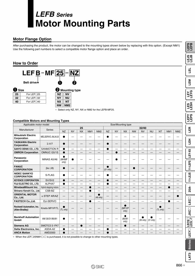
Motor Flange Option
NZMF 25BLEFBelt drive
* Select only NZ, NY, NX or NM2 for the LEFB-MF25.
How to Order
LEFB Series
Motor Mounting Parts
q Size w Mounting type
q w
25 For LEFl25
32 For LEFl32
40 For LEFl40
Compatible Motors and Mounting Types
After purchasing the product, the motor can be changed to the mounting types shown below by replacing with this option. (Except NM1) Use the following part numbers to select a compatible motor flange option and place an order.
* When the LEFm25NM1m-m is purchased, it is not possible to change to other mounting types.
NZNYNXNW
NVNUNT
NM2
Applicable motor model Size/Mounting type
Manufacturer Series25 32/40
NZ NY NX NM1 NM2 NZ NY NX NW NV NU NT NM1 NM2
Mitsubishi ElectricCorporation
MELSERVO JN/J4/J5 V — — — — V — — — — — — — —
YASKAWA Electric Corporation Σ-V/7 V — — — — V — — — — — — — —
SANYO DENKI CO., LTD. SANMOTION R V — — — — V — — — — — — — —OMRON Corporation OMNUC G5/1S V — — — — — V — — — — — — —
Panasonic Corporation
MINAS A5/A6V
(MHMF only)
V — — — — V — — — — — — —
FANUC CORPORATION βis (-B) V — — — — V
(β1 only) — — V — — — — —
NIDEC SANKYO CORPORATION
S-FLAG V — — — — V — — — — — — — —
KEYENCE CORPORATION SV/SV2 V — — — — V — — — — — — — —FUJI ELECTRIC CO., LTD. ALPHA7 V — — — — V — — — — — — — —MinebeaMitsumi Inc. Hybrid stepping motors — — — V — — — — — — — — V —Shinano Kenshi Co., Ltd. CSB-BZ — — — V — — — — — — — — — —
ORIENTAL MOTOR Co., Ltd. α STEP AR/AZ — — — — V
(46 only) — — — — — — — — V
FASTECH Co.,Ltd. Ezi-SERVO — — — V — — — — — — — — V —
Rockwell Automation, Inc.(Allen-Bradley)
Kinetix MP/VP/TL V(TL only) — — — — — —
V(MP/VP
only)— — — V
(TL only) — —
Beckhoff AutomationGmbH
AM 30/31/80/81 V — — — — — —V
(80/81 only)
— V(30 only)
V(31 only) — — —
Siemens AG SIMOTICS S-1FK7 — — V — — — — V — — — — — —Delta Electronics, Inc. ASDA-A2 V — — — — V — — — — — — — —ANCA Motion AMD2000 V — — — — V — — — — — — — —
866
LE
FS
LE
FB
LE
LL
EJS
LE
JBL
EM
LE
YL
EY
GL
ES
LE
SH
LE
PY
LE
PS
LE
RL
EH
LEY-
X511
-LEF
S11
-LEJ
S25
A-
Moto
rless
LEC
Y�LE
CS
�LE
CS�-
TJX
C�
LE
C�
LA
T3
A
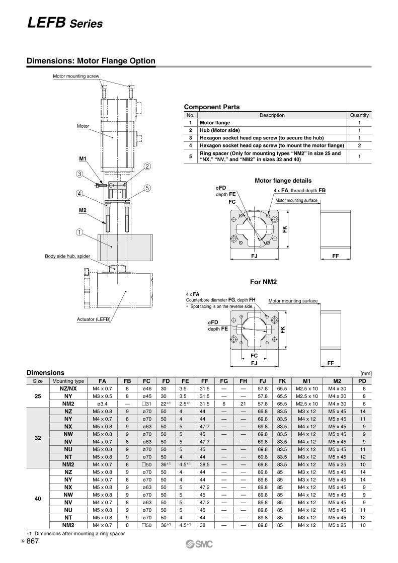
øFDdepth FE
FC
4 x FA, thread depth FB
Motor mounting surface
FFFJ
FK
FFFJFC
4 x FA, Counterbore diameter FG, depth FH∗ Spot facing is on the reverse side.
øFDdepth FE F
K
Motor mounting surface
q
r
ew
t
Motor mounting screw
Motor
M1
M2
Body side hub, spider
Actuator (LEFB)
For NM2
Motor flange details
Dimensions: Motor Flange Option
Size Mounting type FA FB FC FD FE FF FG FH FJ FK M1 M2 PD
25NZ/NX M4 x 0.7 8 ø46 30 3.5 31.5 — — 57.8 65.5 M2.5 x 10 M4 x 30 8
NY M3 x 0.5 8 ø45 30 3.5 31.5 — — 57.8 65.5 M2.5 x 10 M4 x 30 8
NM2 ø3.4 — m31 22*1 2.5*1 31.5 6 21 57.8 65.5 M2.5 x 10 M4 x 30 6
32
NZ M5 x 0.8 9 ø70 50 4 44 — — 69.8 83.5 M3 x 12 M5 x 45 14
NY M4 x 0.7 8 ø70 50 4 44 — — 69.8 83.5 M4 x 12 M5 x 45 11
NX M5 x 0.8 9 ø63 50 5 47.7 — — 69.8 83.5 M4 x 12 M5 x 45 9
NW M5 x 0.8 9 ø70 50 5 45 — — 69.8 83.5 M4 x 12 M5 x 45 9
NV M4 x 0.7 8 ø63 50 5 47.7 — — 69.8 83.5 M4 x 12 M5 x 45 9
NU M5 x 0.8 9 ø70 50 5 45 — — 69.8 83.5 M4 x 12 M5 x 45 11
NT M5 x 0.8 9 ø70 50 4 44 — — 69.8 83.5 M3 x 12 M5 x 45 12
NM2 M4 x 0.7 8 m50 36*1 4.5*1 38.5 — — 69.8 83.5 M4 x 12 M5 x 25 10
40
NZ M5 x 0.8 9 ø70 50 4 44 — — 89.8 85 M3 x 12 M5 x 45 14
NY M4 x 0.7 8 ø70 50 4 44 — — 89.8 85 M3 x 12 M5 x 45 14
NX M5 x 0.8 9 ø63 50 5 47.2 — — 89.8 85 M4 x 12 M5 x 45 9
NW M5 x 0.8 9 ø70 50 5 45 — — 89.8 85 M4 x 12 M5 x 45 9
NV M4 x 0.7 8 ø63 50 5 47.2 — — 89.8 85 M4 x 12 M5 x 45 9
NU M5 x 0.8 9 ø70 50 5 45 — — 89.8 85 M4 x 12 M5 x 45 11
NT M5 x 0.8 9 ø70 50 4 44 — — 89.8 85 M3 x 12 M5 x 45 12
NM2 M4 x 0.7 8 m50 36*1 4.5*1 38 — — 89.8 85 M4 x 12 M5 x 25 10
Dimensions [mm]
Component PartsNo. Description Quantity
1 Motor flange 1
2 Hub (Motor side) 1
3 Hexagon socket head cap screw (to secure the hub) 1
4 Hexagon socket head cap screw (to mount the motor flange) 2
5Ring spacer (Only for mounting types “NM2” in size 25 and “NX,” “NV,” and “NM2” in sizes 32 and 40)
1
*1 Dimensions after mounting a ring spacer
867
LEFB Series
A
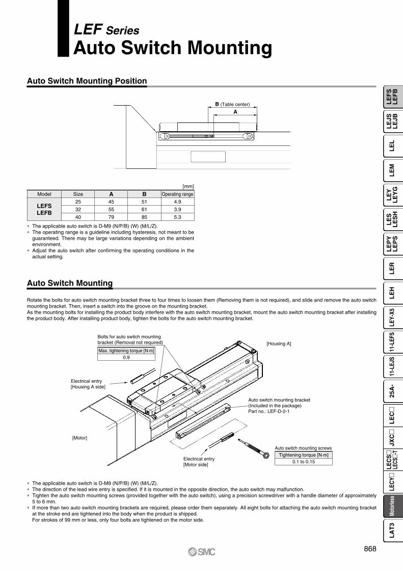
Rotate the bolts for auto switch mounting bracket three to four times to loosen them (Removing them is not required), and slide and remove the auto switch mounting bracket. Then, insert a switch into the groove on the mounting bracket.As the mounting bolts for installing the product body interfere with the auto switch mounting bracket, mount the auto switch mounting bracket after installing the product body. After installing product body, tighten the bolts for the auto switch mounting bracket.
LEF Series
Auto Switch Mounting
Auto Switch Mounting Position
Auto Switch Mounting
[mm]
Model Size A B Operating range
LEFSLEFB
25 45 51 4.9
32 55 61 3.9
40 79 85 5.3
∗ The applicable auto switch is D-M9 (N/P/B) (W) (M/L/Z).∗ The operating range is a guideline including hysteresis, not meant to be
guaranteed. There may be large variations depending on the ambient environment.
∗ Adjust the auto switch after confirming the operating conditions in the actual setting.
∗ The applicable auto switch is D-M9 (N/P/B) (W) (M/L/Z).∗ The direction of the lead wire entry is specified. If it is mounted in the opposite direction, the auto switch may malfunction.∗ Tighten the auto switch mounting screws (provided together with the auto switch), using a precision screwdriver with a handle diameter of approximately
5 to 6 mm.∗ If more than two auto switch mounting brackets are required, please order them separately. All eight bolts for attaching the auto switch mounting bracket
at the stroke end are tightened into the body when the product is shipped.For strokes of 99 mm or less, only four bolts are tightened on the motor side.
B (Table center)
A
Bolts for auto switch mounting bracket (Removal not required)
Auto switch mounting bracket (Included in the package)Part no.: LEF-D-2-1
Electrical entry [Motor side]
[Motor]
Auto switch mounting screws
Electrical entry [Housing A side]
[Housing A]
Max. tightening torque [N·m]0.9
Tightening torque [N·m]0.1 to 0.15
868
LE
FS
LE
FB
LE
LL
EJS
LE
JBL
EM
LE
YL
EY
GL
ES
LE
SH
LE
PY
LE
PS
LE
RL
EH
LEY-
X511
-LEF
S11
-LEJ
S25
A-
Moto
rless
LEC
Y�LE
CS
�LE
CS�-
TJX
C�
LE
C�
LA
T3
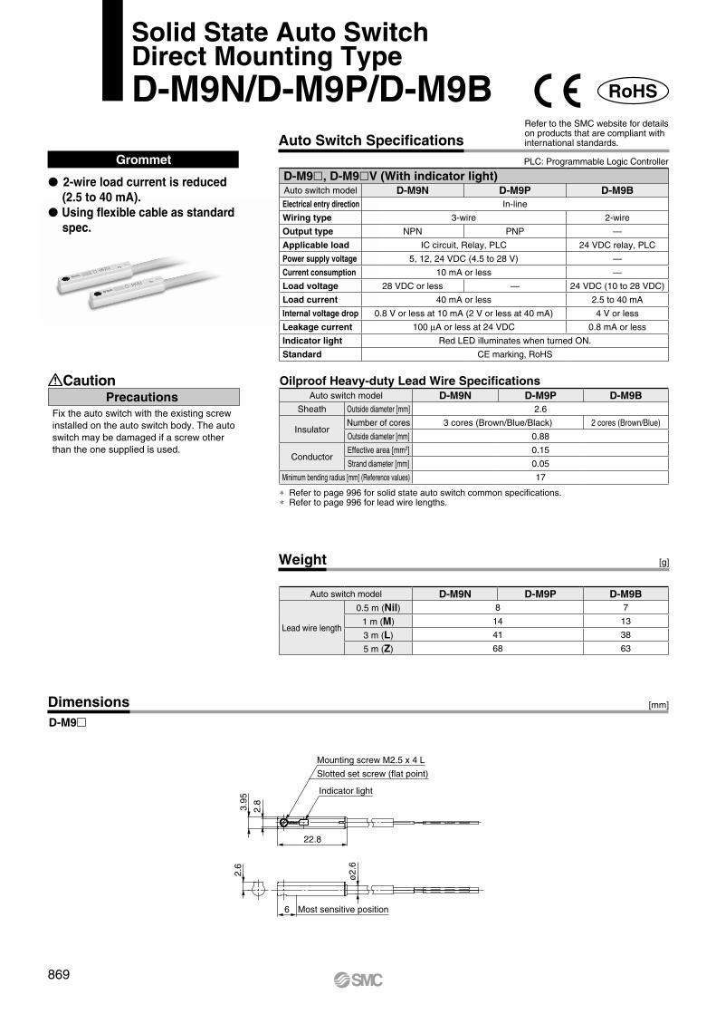
PrecautionsCaution
Fix the auto switch with the existing screw installed on the auto switch body. The auto switch may be damaged if a screw other than the one supplied is used.
Weight [g]
Grommet
∗ Refer to page 996 for solid state auto switch common specifications.∗ Refer to page 996 for lead wire lengths.
DimensionsD-M9m
P 2-wire load current is reduced (2.5 to 40 mA).
P Using flexible cable as standard spec.
[mm]
Oilproof Heavy-duty Lead Wire Specifications
Solid State Auto SwitchDirect Mounting TypeD-M9N/D-M9P/D-M9B
Auto Switch SpecificationsPLC: Programmable Logic Controller
Refer to the SMC website for details on products that are compliant with international standards.
RoHS
Most sensitive position
ø2.
6
2.6
3.95
2.8
6
22.8
Mounting screw M2.5 x 4 L
Slotted set screw (flat point)
Indicator light
D-M9l, D-M9lV (With indicator light)Auto switch model D-M9N D-M9P D-M9BElectrical entry direction In-line
Wiring type 3-wire 2-wire
Output type NPN PNP —
Applicable load IC circuit, Relay, PLC 24 VDC relay, PLC
Power supply voltage 5, 12, 24 VDC (4.5 to 28 V) —
Current consumption 10 mA or less —
Load voltage 28 VDC or less — 24 VDC (10 to 28 VDC)
Load current 40 mA or less 2.5 to 40 mA
Internal voltage drop 0.8 V or less at 10 mA (2 V or less at 40 mA) 4 V or less
Leakage current 100 mA or less at 24 VDC 0.8 mA or less
Indicator light Red LED illuminates when turned ON.
Standard CE marking, RoHS
Auto switch model D-M9N D-M9P D-M9BSheath Outside diameter [mm] 2.6
InsulatorNumber of cores 3 cores (Brown/Blue/Black) 2 cores (Brown/Blue)
Outside diameter [mm] 0.88
ConductorEffective area [mm2] 0.15
Strand diameter [mm] 0.05
Minimum bending radius [mm] (Reference values) 17
Auto switch model D-M9N D-M9P D-M9B
Lead wire length
0.5 m (Nil) 8 7
1 m (M) 14 13
3 m (L) 41 38
5 m (Z) 68 63
869
PrecautionsCaution
Fix the auto switch with the existing screw installed on the auto switch body. The auto switch may be damaged if a screw other than the one supplied is used.
Weight [g]
∗ Refer to page 996 for solid state auto switch common specifications.∗ Refer to page 996 for lead wire lengths.
DimensionsD-M9mE D-M9mEV
[mm]
Oilproof Heavy-duty Lead Wire Specifications
Normally Closed Solid State Auto SwitchDirect Mounting TypeD-M9NE(V)/D-M9PE(V)/D-M9BE(V)
Auto Switch SpecificationsPLC: Programmable Logic Controller
Refer to the SMC website for details on products that are compliant with international standards.
∗1 The 1 m and 5 m options are produced upon receipt of order.
Grommet
P Output signal turns on when no magnetic force is detected.
P Can be used for the actuator adopted by the solid state auto switch D-M9 series (excluding special order products)
RoHS
Most sensitive position
ø2.
6
2.6
3.95
2.8
6
22.8
Mounting screw M2.5 x 4 L
Slotted set screw (flat point)
Indicator light
19.5
15.9
7.5
9.5
4
2.6
0.3
ø2.6
Indicator light
Slotted set screw2
Most sensitive position6
2.8
4.6
500
(100
0) (
3000
) (5
000)
Mounting screw M2.5 x 4 L
D-M9lE, D-M9lEV (With indicator light)Auto switch model D-M9NE D-M9NEV D-M9PE D-M9PEV D-M9BE D-M9BEVElectrical entry direction In-line Perpendicular In-line Perpendicular In-line Perpendicular
Wiring type 3-wire 2-wire
Output type NPN PNP —
Applicable load IC circuit, Relay, PLC 24 VDC relay, PLC
Power supply voltage 5, 12, 24 VDC (4.5 to 28 V) —
Current consumption 10 mA or less —
Load voltage 28 VDC or less — 24 VDC (10 to 28 VDC)
Load current 40 mA or less 2.5 to 40 mA
Internal voltage drop 0.8 V or less at 10 mA (2 V or less at 40 mA) 4 V or less
Leakage current 100 mA or less at 24 VDC 0.8 mA or less
Indicator light Red LED illuminates when turned ON.
Standard CE marking, RoHS
Auto switch model D-M9NE(V) D-M9PE(V) D-M9BE(V)Sheath Outside diameter [mm] 2.6
InsulatorNumber of cores 3 cores (Brown/Blue/Black) 2 cores (Brown/Blue)
Outside diameter [mm] 0.88
ConductorEffective area [mm2] 0.15
Strand diameter [mm] 0.05
Minimum bending radius [mm] (Reference values) 17
Auto switch model D-M9NE(V) D-M9PE(V) D-M9BE(V)
Lead wire length
0.5 m (Nil) 8 7
1 m (M)∗1 14 13
3 m (L) 41 38
5 m (Z)∗1 68 63
870
LE
FS
LE
FB
LE
LL
EJS
LE
JBL
EM
LE
YL
EY
GL
ES
LE
SH
LE
PY
LE
PS
LE
RL
EH
LEY-
X511
-LEF
S11
-LEJ
S25
A-
Moto
rless
LEC
Y�LE
CS
�LE
CS�-
TJX
C�
LE
C�
LA
T3
Weight [g]
[mm]Dimensions
Grommet
∗ Refer to page 996 for solid state auto switch common specifications.∗ Refer to page 996 for lead wire lengths.
P 2-wire load current is reduced (2.5 to 40 mA).
P Using flexible cable as standard spec.
P The proper operating range can be determined by the color of the light. (Red → Green ← Red)
D-M9mW
Oilproof Flexible Heavy-duty Lead Wire Specifications
2-Color Indicator Solid State Auto SwitchDirect Mounting TypeD-M9NW/D-M9PW/D-M9BW
PrecautionsCaution
Fix the auto switch with the existing screw installed on the auto switch body. The auto switch may be damaged if a screw other than the one supplied is used.
Auto Switch SpecificationsRefer to the SMC website for details on products that are compliant with international standards.
PLC: Programmable Logic Controller
RoHS
6 Most sensitive position
2.6
ø2.
6
22.8
Indicator light
3.95
2.8
Slotted set screw (flat point)
Mounting screw M2.5 x 4 L
D-M9lW, D-M9lWV (With indicator light)Auto switch model D-M9NW D-M9PW D-M9BWElectrical entry direction In-line
Wiring type 3-wire 2-wire
Output type NPN PNP —
Applicable load IC circuit, Relay, PLC 24 VDC relay, PLC
Power supply voltage 5, 12, 24 VDC (4.5 to 28 V) —
Current consumption 10 mA or less —
Load voltage 28 VDC or less — 24 VDC (10 to 28 VDC)
Load current 40 mA or less 2.5 to 40 mA
Internal voltage drop 0.8 V or less at 10 mA (2 V or less at 40 mA) 4 V or less
Leakage current 100 mA or less at 24 VDC 0.8 mA or less
Indicator lightOperating range .......... Red LED illuminates.Proper operating range .......... Green LED illuminates.
Standard CE marking, RoHS
Auto switch model D-M9NW D-M9PW D-M9BWSheath Outside diameter [mm] 2.6
InsulatorNumber of cores 3 cores (Brown/Blue/Black) 2 cores (Brown/Blue)
Outside diameter [mm] 0.88
ConductorEffective area [mm2] 0.15
Strand diameter [mm] 0.05
Minimum bending radius [mm] (Reference values) 17
Auto switch model D-M9NW D-M9PW D-M9BW
Lead wire length
0.5 m (Nil) 8 7
1 m (M) 14 13
3 m (L) 41 38
5 m (Z) 68 63
871
Design
Caution1. Do not apply a load in excess of the specification limits.
Select a suitable actuator by work load and allowable moment. If a load in excess of the specification limits is applied to the guide, adverse effects such as the generation of play in the guide, reduced accuracy, or reduced service life of the product may occur.
2. Do not use the product in applications where exces-sive external force or impact force is applied to it.This can cause a malfunction.
Handling
Caution
Selection
Warning1. Do not increase the speed in excess of the specifi-
cation limits.Select a suitable actuator by the relationship of the allowable work load and speed, and the allowable speed of each stroke. If the product is used outside of the specification limits, ad-verse effects such as the generation of noise, reduced accura-cy, or reduced service life of the product may occur.
2. Do not use the product in applications where exces-sive external force or impact force is applied to it. This can cause a malfunction.
3. When the product repeatedly cycles with partial strokes (see the table below), operate it at a full stroke at least once every few dozens of cycles.Failure to do so may result in the product running out of lubrication.
4. When external force is to be applied to the table, it is necessary to add the external force to the work load as the total carried load when selecting a size.When a cable duct or flexible moving tube is attached to the ac-tuator, the sliding resistance of the table will increase, which may lead to the malfunction of the product.
5. Depending on the shape of the motor to be mount-ed, some of the product’s interior parts (hub, spi-der, etc.) may be visible from the motor mounting surface. If this is undesirable, please contact your nearest sales office for details on options such as covers.
1. Never allow the table to collide with the stroke end.When the driver parameters, origin or programs are set incor-rectly, the table may collide with the stroke end of the actuator during operation. Be sure to check these points before use. If the table collides with the stroke end of the actuator, the guide, ball screw, belt, or internal stopper may break. This can result in abnormal operation.
Handle the actuator with care when it is used in the vertical di-rection as the workpiece will fall freely from its own weight.
2. The actual speed of this actuator is affected by the work load and stroke.Check the model selection section of the catalog.
3. Do not apply a load, impact, or resistance in addi-tion to the transferred load during return to origin.
4. Do not dent, scratch, or cause other damage to the body or table mounting surfaces.Doing so may cause unevenness in the mounting surface, play in the guide, or an increase in the sliding resistance.
5. Do not apply strong impact or an excessive moment while mounting a workpiece.If an external force over the allowable moment is applied, it may cause play in the guide or an increase in the sliding resistance.
6. Keep the flatness of the mounting surface within 0.1 mm/500 mm.If a workpiece or base does not sit evenly on the body of the product, play in the guide or an increase in the sliding resist-ance may occur.
7. Do not allow a workpiece to collide with the table during the positioning operation or within the posi-tioning range.
8. Grease is applied to the dust seal band for sliding. When wiping off the grease to remove foreign matter, etc., be sure to apply it again.
9. When bottom mounted, the dust seal band may be-come warped.
LEF SeriesSpecific Product Precautions 1Be sure to read this before handling the products. Refer to page 984 for safety instructions, pages 985 to 990 for electric actuator precautions, and pages 991 to 1000 for auto switch precautions.
Model Partial stroke
LEFl25 65 mm or less
LEFl32 70 mm or less
LEFl40 105 mm or less
872
LE
FS
LE
FB
LE
LL
EJS
LE
JBL
EM
LE
YL
EY
GL
ES
LE
SH
LE
PY
LE
PS
LE
RL
EH
LEY-
X511
-LEF
S11
-LEJ
S25
A-
Moto
rless
LEC
Y�LE
CS
�LE
CS�-
TJX
C�
LE
C�
LA
T3
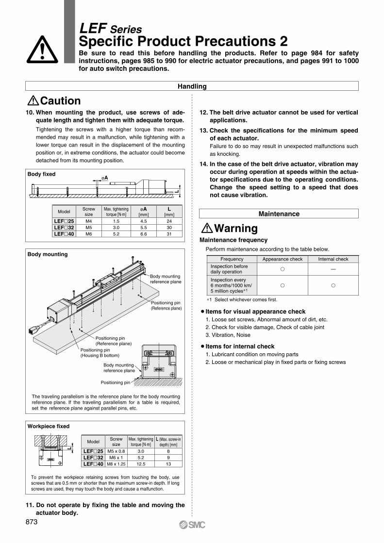
øAL
Body mounting reference plane
Positioning pin (Reference plane)
Positioning pin(Reference plane)
Positioning pin (Housing B bottom)
Positioning pin
Body mounting reference plane
L
To prevent the workpiece retaining screws from touching the body, use screws that are 0.5 mm or shorter than the maximum screw-in depth. If long screws are used, they may touch the body and cause a malfunction.
Workpiece fixed
Body fixed
Body mounting
The traveling parallelism is the reference plane for the body mounting reference plane. If the traveling parallelism for a table is required, set the reference plane against parallel pins, etc.
Maintenance
WarningMaintenance frequency
Perform maintenance according to the table below.
¡Items for visual appearance check1. Loose set screws, Abnormal amount of dirt, etc.2. Check for visible damage, Check of cable joint3. Vibration, Noise
¡Items for internal check1. Lubricant condition on moving parts2. Loose or mechanical play in fixed parts or fixing screws
∗1 Select whichever comes first.
Handling
Caution10. When mounting the product, use screws of ade-
quate length and tighten them with adequate torque.Tightening the screws with a higher torque than recom-mended may result in a malfunction, while tightening with a lower torque can result in the displacement of the mounting position or, in extreme conditions, the actuator could become detached from its mounting position.
12. The belt drive actuator cannot be used for vertical applications.
13. Check the specifications for the minimum speed of each actuator.Failure to do so may result in unexpected malfunctions such as knocking.
14. In the case of the belt drive actuator, vibration may occur during operation at speeds within the actua-tor specifications due to the operating conditions. Change the speed setting to a speed that does not cause vibration.
11. Do not operate by fixing the table and moving the actuator body.
LEF SeriesSpecific Product Precautions 2
Frequency Appearance check Internal check
Inspection beforedaily operation v —
Inspection every6 months/1000 km/5 million cycles∗1
v v
ModelScrewsize
Max. tighteningtorque [N·m]
øA[mm]
L[mm]
LEFl25 M4 1.5 4.5 24
LEFl32 M5 3.0 5.5 30
LEFl40 M6 5.2 6.6 31
ModelScrewsize
Max. tighteningtorque [N·m]
L (Max. screw-indepth) [mm]
LEFl25 M5 x 0.8 3.0 8
LEFl32 M6 x 1 5.2 9
LEFl40 M8 x 1.25 12.5 13
Be sure to read this before handling the products. Refer to page 984 for safety instructions, pages 985 to 990 for electric actuator precautions, and pages 991 to 1000 for auto switch precautions.
873
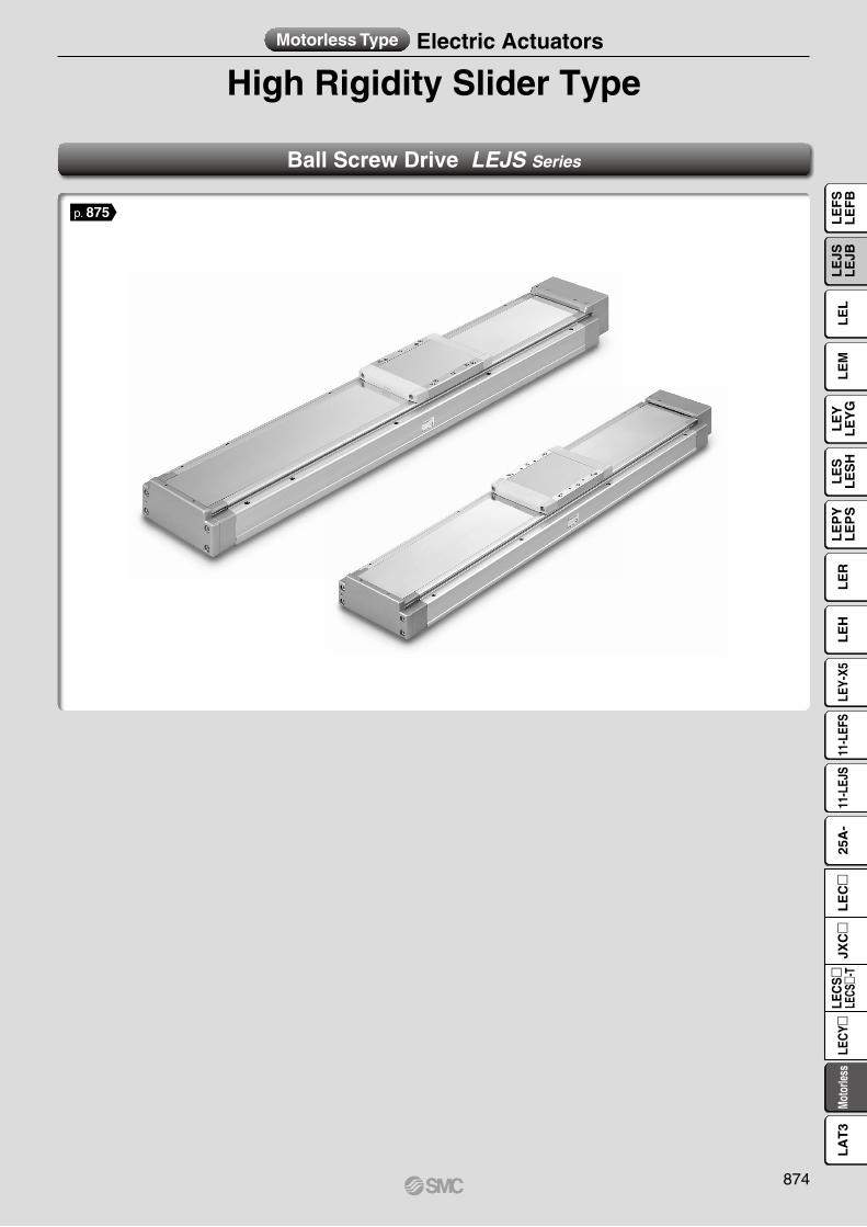
High Rigidity Slider TypeMotorless Type Electric Actuators
Ball Screw Drive LEJS Series
p. 875
874
LE
FS
LE
FB
LE
LL
EJS
LE
JBL
EM
LE
YL
EY
GL
ES
LE
SH
LE
PY
LE
PS
LE
RL
EH
LEY-
X511
-LEF
S11
-LEJ
S25
A-
Moto
rless
LEC
Y�LE
CS
�LE
CS�-
TJX
C�
LE
C�
LA
T3
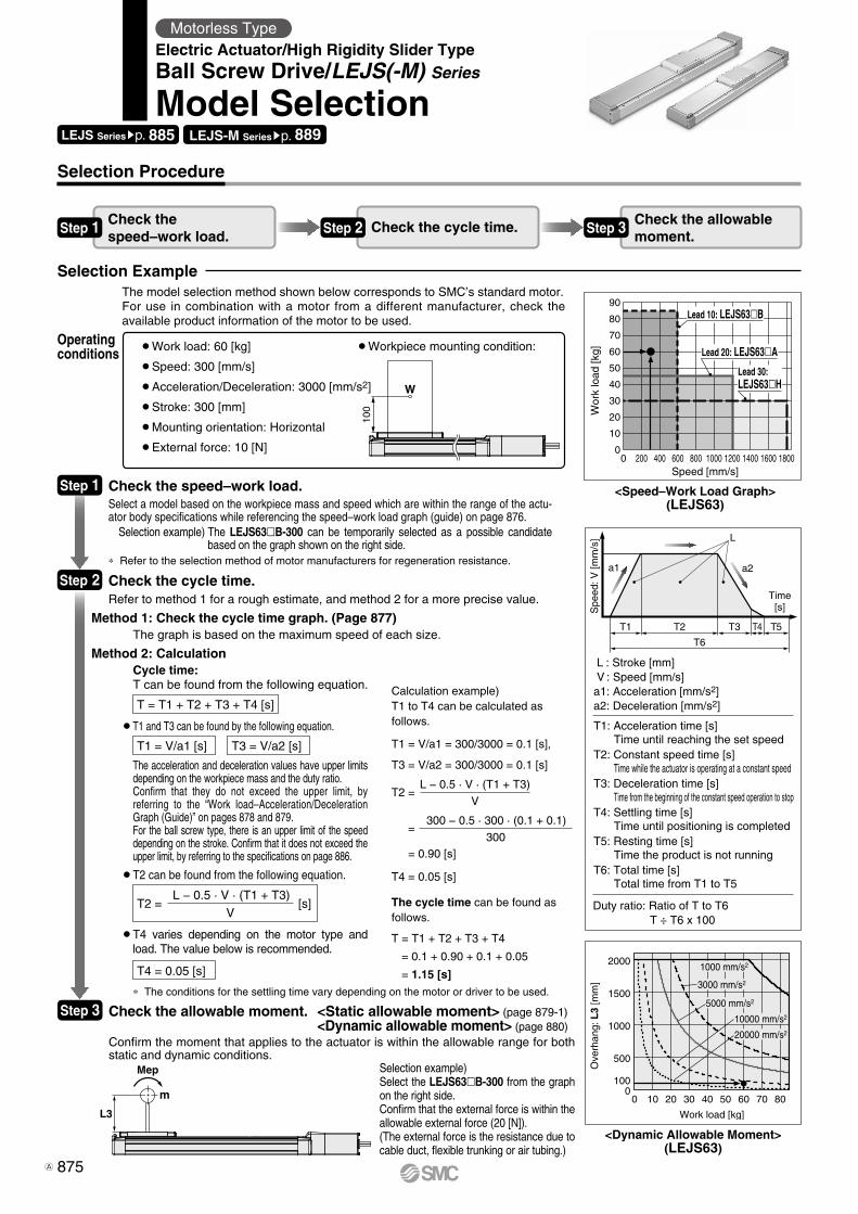
0
10
20
30
40
50
60
70
80
90
0 200 400 600 800 1000 1200 1400 1600 1800
Wor
k lo
ad [k
g]
Speed [mm/s]
Lead 20: LEJS63�A
Lead 10: LEJS63�B
Lead 30: LEJS63�H
T1
a1 a2
L
Spe
ed: V
[mm
/s]
Time[s]
T2
T6
T3 T4 T5
L3
Mep
m
100
W
20000 mm/s2
10000 mm/s2
5000 mm/s2
3000 mm/s2
1000 mm/s2
Ove
rhan
g: L
3 [m
m]
Work load [kg]
0
500
1000
1500
2000
0 10 20 30 40 50 60 70 80
100
Selection Procedure
Selection Example
Step 1 Check the speed–work load. Step 2 Check the cycle time. Step 3 Check the allowable
moment.
¡Work load: 60 [kg]
¡Speed: 300 [mm/s]
¡Acceleration/Deceleration: 3000 [mm/s2]
¡Stroke: 300 [mm]
¡Mounting orientation: Horizontal
¡External force: 10 [N]
¡Workpiece mounting condition:Operating conditions
<Speed–Work Load Graph>(LEJS63)
Step 1 Check the speed–work load.Select a model based on the workpiece mass and speed which are within the range of the actu-ator body specifications while referencing the speed–work load graph (guide) on page 876. Selection example) The LEJS63lB-300 can be temporarily selected as a possible candidate
based on the graph shown on the right side.
Step 2 Check the cycle time.
Method 2: Calculation
Refer to method 1 for a rough estimate, and method 2 for a more precise value.
Cycle time: T can be found from the following equation.
Method 1: Check the cycle time graph. (Page 877)The graph is based on the maximum speed of each size.
T = T1 + T2 + T3 + T4 [s]
T4 = 0.05 [s]
T1 = V/a1 [s] T3 = V/a2 [s]
T2 = [s]L − 0.5 · V · (T1 + T3)
V
¡T4 varies depending on the motor type and load. The value below is recommended.
¡T2 can be found from the following equation.
¡T1 and T3 can be found by the following equation.
The acceleration and deceleration values have upper limits depending on the workpiece mass and the duty ratio.Confirm that they do not exceed the upper limit, by referring to the “Work load–Acceleration/Deceleration Graph (Guide)” on pages 878 and 879.For the ball screw type, there is an upper limit of the speed depending on the stroke. Confirm that it does not exceed the upper limit, by referring to the specifications on page 886.
Step 3
<Dynamic Allowable Moment>(LEJS63)
L : Stroke [mm]V : Speed [mm/s]
a1: Acceleration [mm/s2]a2: Deceleration [mm/s2]
Duty ratio: Ratio of T to T6T ÷ T6 x 100
T1: Acceleration time [s]Time until reaching the set speed
T2: Constant speed time [s]Time while the actuator is operating at a constant speed
T3: Deceleration time [s]Time from the beginning of the constant speed operation to stop
T4: Settling time [s]Time until positioning is completed
T5: Resting time [s]Time the product is not running
T6: Total time [s]Total time from T1 to T5
Calculation example)T1 to T4 can be calculated as follows.
T1 = V/a1 = 300/3000 = 0.1 [s],
T3 = V/a2 = 300/3000 = 0.1 [s]
T4 = 0.05 [s]
The cycle time can be found as follows.
T = T1 + T2 + T3 + T4
= 0.1 + 0.90 + 0.1 + 0.05
= 1.15 [s]
T2 =
=
= 0.90 [s]
L − 0.5 · V · (T1 + T3)
V
300 − 0.5 · 300 · (0.1 + 0.1)
300
Selection example) Select the LEJS63lB-300 from the graph on the right side.Confirm that the external force is within the allowable external force (20 [N]).(The external force is the resistance due to cable duct, flexible trunking or air tubing.)
* The conditions for the settling time vary depending on the motor or driver to be used.
* Refer to the selection method of motor manufacturers for regeneration resistance.
LEJS Seriessp. 885 LEJS-M Seriessp. 889
Motorless TypeElectric Actuator/High Rigidity Slider TypeBall Screw Drive/LEJS(-M) Series
Model Selection
The model selection method shown below corresponds to SMC’s standard motor.For use in combination with a motor from a different manufacturer, check the available product information of the motor to be used.
Check the allowable moment. <Static allowable moment> (page 879-1) <Dynamic allowable moment> (page 880)Confirm the moment that applies to the actuator is within the allowable range for both static and dynamic conditions.
875A
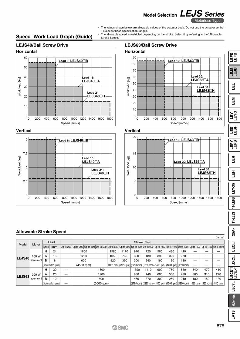
Wor
k lo
ad [k
g]
Speed [mm/s]
0
10
20
30
40
50
60
0 200 400 600 800 1000 1200 1400 1600 1800
Lead 16: LEJS40�A
Lead 8: LEJS40�B
Lead 24: LEJS40�H
10
20
30
40
50
60
70
80
90
0 200 400 600 800 1000 1200 1400 1600 1800
Wor
k lo
ad [k
g]Speed [mm/s]
0
Lead 20: LEJS63�A
Lead 10: LEJS63�B
Lead 30: LEJS63�H
0 200 400 600 800 1000 1200 1400 1600 18000
5
10
7.5
2.5
Wor
k lo
ad [k
g]
Speed [mm/s]
Lead 16: LEJS40�A
Lead 8: LEJS40�B
Lead 24: LEJS40�H
5
10
15
20
0 200 400 600 800 1000 1200 1400 1600 1800
Wor
k lo
ad [k
g]
Speed [mm/s]
0
Lead 20: LEJS63�A
Lead 10: LEJS63�B
Lead 30: LEJS63�H
Speed−Work Load Graph (Guide)
* The values shown below are allowable values of the actuator body. Do not use the actuator so that it exceeds these specification ranges.
* The allowable speed is restricted depending on the stroke. Select it by referring to the “Allowable Stroke Speed.”
LEJS40/Ball Screw Drive LEJS63/Ball Screw DriveHorizontal Horizontal
Vertical Vertical
Allowable Stroke Speed[mm/s]
Model MotorLead Stroke [mm]
Symbol [mm] Up to 200 Up to 300 Up to 400 Up to 500 Up to 600 Up to 700 Up to 800 Up to 900 Up to 1000 Up to 1100 Up to 1200 Up to 1300 Up to 1400 Up to 1500
LEJS40 100 Wequivalent
H 24 1800 1580 1170 910 720 580 480 410 — — —
A 16 1200 1050 780 600 480 390 320 270 — — —
B 8 600 520 390 300 240 190 160 130 — — —
(Motor rotation speed) (4500 rpm) (3938 rpm) (2925 rpm) (2250 rpm) (1800 rpm) (1463 rpm) (1200 rpm) (1013 rpm) — — —
LEJS63 200 Wequivalent
H 30 — 1800 1390 1110 900 750 630 540 470 410
A 20 — 1200 930 740 600 500 420 360 310 270
B 10 — 600 460 370 300 250 210 180 150 130
(Motor rotation speed) — (3600 rpm) (2790 rpm) (2220 rpm) (1800 rpm) (1500 rpm) (1260 rpm) (1080 rpm) (930 rpm) (810 rpm)
876
Model Selection LEJS SeriesMotorless Type
LE
FS
LE
FB
LE
LL
EJS
LE
JBL
EM
LE
YL
EY
GL
ES
LE
SH
LE
PY
LE
PS
LE
RL
EH
LEY-
X511
-LEF
S11
-LEJ
S25
A-
Moto
rless
LEC
Y�LE
CS
�LE
CS�-
TJX
C�
LE
C�
LA
T3
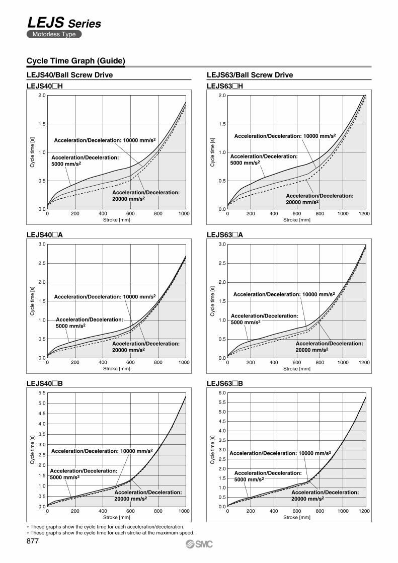
Acceleration/Deceleration: 10000 mm/s2
Acceleration/Deceleration: 20000 mm/s2
Acceleration/Deceleration: 5000 mm/s2
Cyc
le ti
me
[s]
Stroke [mm]0 1200200 400 600 800 1000
0.0
0.5
1.0
1.5
2.0
Cyc
le ti
me
[s]
Stroke [mm]0 12001000200 400 600 800
0.0
0.5
1.0
1.5
2.0
2.5
3.0
Acceleration/Deceleration: 5000 mm/s2
Acceleration/Deceleration: 10000 mm/s2
Acceleration/Deceleration: 20000 mm/s2
Cyc
le ti
me
[s]
Stroke [mm]0 1200200 400 600 800 1000
0.0
0.5
1.0
1.5
2.0
2.5
3.0
3.5
4.0
4.5
5.0
5.5
6.0
Acceleration/Deceleration: 5000 mm/s2
Acceleration/Deceleration: 10000 mm/s2
Acceleration/Deceleration: 20000 mm/s2
Acceleration/Deceleration: 10000 mm/s2
Acceleration/Deceleration: 20000 mm/s2
1000200 400 600 800
Acceleration/Deceleration: 5000 mm/s2
Cyc
le ti
me
[s]
Stroke [mm]0
0.0
0.5
1.0
1.5
2.0
Cyc
le ti
me
[s]
Stroke [mm]0 1000200 400 600 800
0.0
0.5
1.0
1.5
2.0
2.5
3.0
Acceleration/Deceleration: 5000 mm/s2
Acceleration/Deceleration: 10000 mm/s2
Acceleration/Deceleration: 20000 mm/s2
Cyc
le ti
me
[s]
Stroke [mm]0 1000200 400 600 800
0.0
0.5
1.0
1.5
2.0
2.5
3.0
3.5
4.0
4.5
5.0
5.5
Acceleration/Deceleration: 5000 mm/s2
Acceleration/Deceleration: 10000 mm/s2
Acceleration/Deceleration: 20000 mm/s2
Cycle Time Graph (Guide)
LEJS40/Ball Screw Drive LEJS63/Ball Screw Drive
LEJS40mH LEJS63mH
* These graphs show the cycle time for each acceleration/deceleration.* These graphs show the cycle time for each stroke at the maximum speed.
LEJS40mA
LEJS40mB
LEJS63mA
LEJS63mB
877
LEJS SeriesMotorless Type
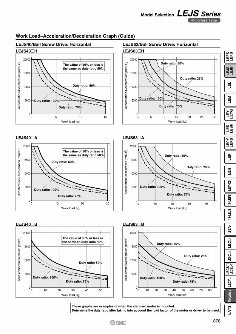
0
5000
10000
15000
20000
0 5 10 15
Work load [kg]
Acc
eler
atio
n/D
ecel
erat
ion
[mm
/s2 ]
Duty ratio: 100%
Duty ratio: 75%
Duty ratio: 50%
The value of 50% or less isthe same as duty ratio 50%
0
5000
10000
15000
20000
0 5 10 20 3015 25
Work load [kg]A
ccel
erat
ion/
Dec
eler
atio
n [m
m/s
2 ]
Duty ratio: 100%
Duty ratio: 75%
Duty ratio: 50%
Duty ratio: 25%
5000
10000
15000
20000
0 10 20 30
Work load [kg]
Acc
eler
atio
n/D
ecel
erat
ion
[mm
/s2 ]
Duty ratio: 100%
Duty ratio: 75%
Duty ratio: 50%
0
The value of 50% or less isthe same as duty ratio 50%
0
5000
10000
15000
20000
0 10 20 30 40
Work load [kg]
Acc
eler
atio
n/D
ecel
erat
ion
[mm
/s2 ]
Duty ratio: 100%
Duty ratio: 50%
Duty ratio: 25%
Duty ratio: 75%
0
5000
10000
15000
20000
0 10 20 30 40 50
Work load [kg]
Acc
eler
atio
n/D
ecel
erat
ion
[mm
/s2 ]
Duty ratio: 100%
Duty ratio: 50%
Duty ratio: 75%
The value of 50% or less isthe same as duty ratio 50%
0
5000
10000
15000
20000
0 10 20 30 40 50 60 70 80
Work load [kg]
Acc
eler
atio
n/D
ecel
erat
ion
[mm
/s2 ]
Duty ratio: 100%
Duty ratio: 50%
Duty ratio: 25%
Duty ratio: 75%
Work Load–Acceleration/Deceleration Graph (Guide)
LEJS40/Ball Screw Drive: Horizontal
LEJS40mH LEJS63mH
LEJS63/Ball Screw Drive: Horizontal
LEJS40mA LEJS63mA
LEJS40mB LEJS63mB
These graphs are examples of when the standard motor is mounted.Determine the duty ratio after taking into account the load factor of the motor or driver to be used.
878
Model Selection LEJS SeriesMotorless Type
LE
FS
LE
FB
LE
LL
EJS
LE
JBL
EM
LE
YL
EY
GL
ES
LE
SH
LE
PY
LE
PS
LE
RL
EH
LEY-
X511
-LEF
S11
-LEJ
S25
A-
Moto
rless
LEC
Y�LE
CS
�LE
CS�-
TJX
C�
LE
C�
LA
T3
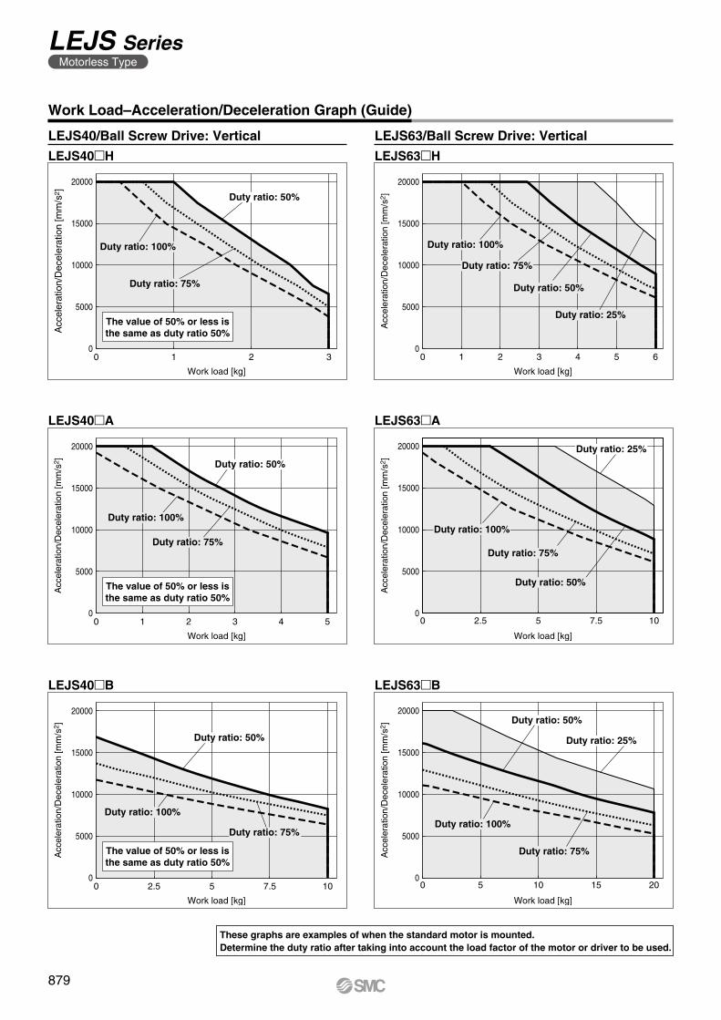
0
5000
10000
15000
20000
0 1 2 3
Work load [kg]
Acc
eler
atio
n/D
ecel
erat
ion
[mm
/s2 ]
Duty ratio: 100%
Duty ratio: 50%
Duty ratio: 75%
The value of 50% or less isthe same as duty ratio 50%
0
5000
10000
15000
20000
0 1 2 3 4 5 6
Work load [kg]A
ccel
erat
ion/
Dec
eler
atio
n [m
m/s
2 ]
Duty ratio: 100%
Duty ratio: 50%
Duty ratio: 25%
Duty ratio: 75%
0 1 2 3 4 50
5000
10000
15000
20000
Work load [kg]
Acc
eler
atio
n/D
ecel
erat
ion
[mm
/s2 ]
Duty ratio: 100%
Duty ratio: 50%
Duty ratio: 75%
The value of 50% or less isthe same as duty ratio 50%
0
5000
10000
15000
20000
0 2.5 5 7.5 10
Work load [kg]
Acc
eler
atio
n/D
ecel
erat
ion
[mm
/s2 ]
Duty ratio: 100%
Duty ratio: 25%
Duty ratio: 75%
Duty ratio: 50%
0
5000
10000
15000
20000
0 2.5 5 7.5 10
Work load [kg]
Acc
eler
atio
n/D
ecel
erat
ion
[mm
/s2 ]
Duty ratio: 100%
Duty ratio: 50%
Duty ratio: 75%
The value of 50% or less isthe same as duty ratio 50%
0
5000
10000
15000
20000
0 5 10 15 20
Work load [kg]
Acc
eler
atio
n/D
ecel
erat
ion
[mm
/s2 ]
Duty ratio: 50%
Duty ratio: 25%
Duty ratio: 75%
Duty ratio: 100%
Work Load–Acceleration/Deceleration Graph (Guide)
LEJS40mH LEJS63mH
LEJS40/Ball Screw Drive: Vertical LEJS63/Ball Screw Drive: Vertical
LEJS40mA LEJS63mA
LEJS40mB LEJS63mB
These graphs are examples of when the standard motor is mounted.Determine the duty ratio after taking into account the load factor of the motor or driver to be used.
879
LEJS SeriesMotorless Type
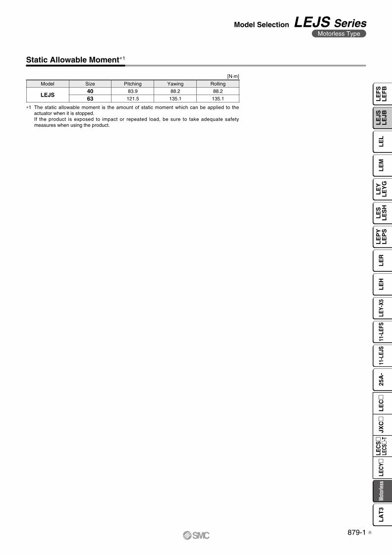
Static Allowable Moment∗1
[N·m]
Model Size Pitching Yawing Rolling
LEJS40 83.9 88.2 88.2
63 121.5 135.1 135.1
∗1 The static allowable moment is the amount of static moment which can be applied to the actuator when it is stopped.If the product is exposed to impact or repeated load, be sure to take adequate safety measures when using the product.
879-1
Model Selection LEJS SeriesMotorless Type
LE
FS
LE
FB
LE
LL
EJS
LE
JBL
EM
LE
YL
EY
GL
ES
LE
SH
LE
PY
LE
PS
LE
RL
EH
LEY-
X511
-LEF
S11
-LEJ
S25
A-
Moto
rless
LEC
Y�LE
CS
�LE
CS�-
TJX
C�
LE
C�
LA
T3
A

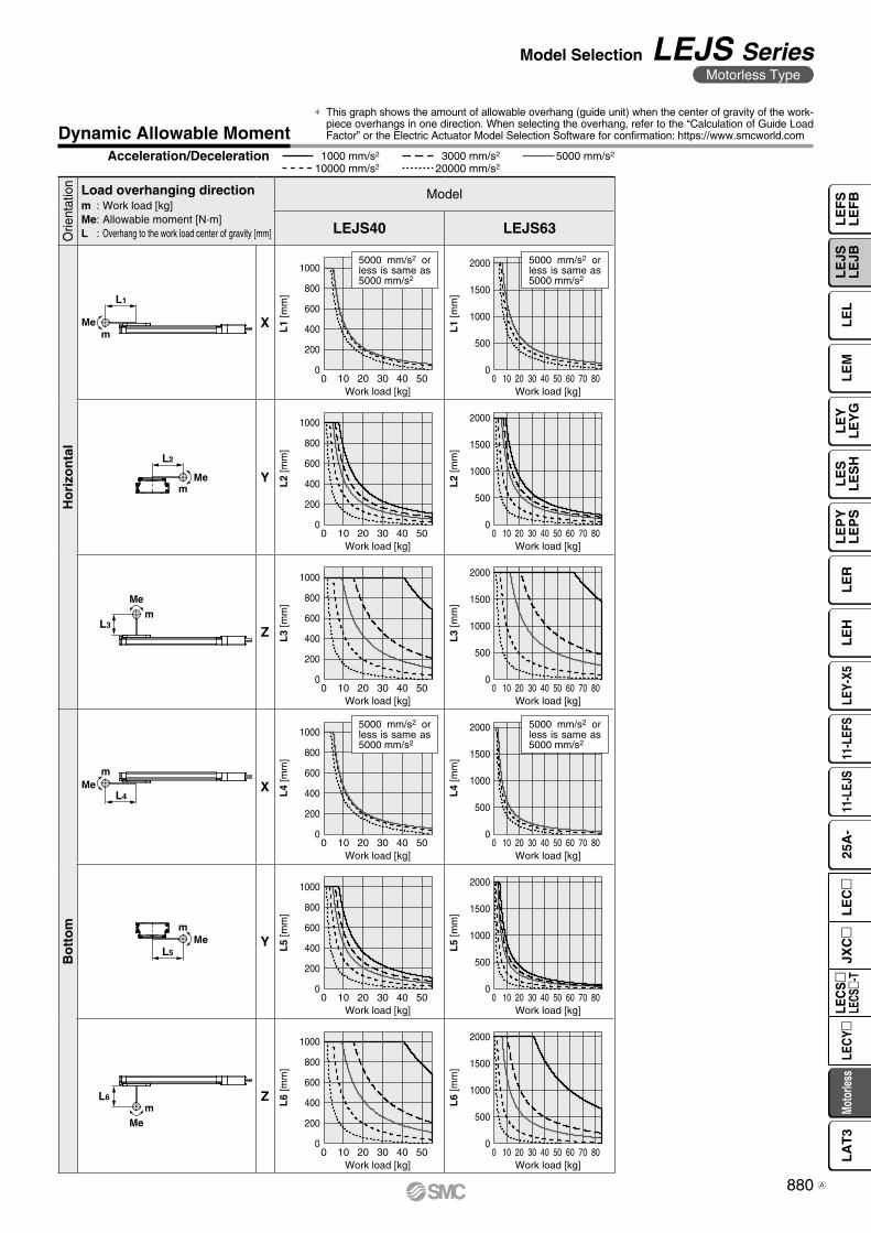
mMe
L1
L2
mMe
mMe
L3
0
200
400
600
800
1000
0
500
1000
1500
2000
L1
[mm
]
L1
[mm
]
0 10 40 5020 300 10 40 5020 30 60 70 80
0
200
400
600
800
1000
0
500
1000
1500
2000
L2
[mm
]
L2
[mm
]
0 10 40 5020 300 10 40 5020 30 60 70 80
0
200
400
600
800
1000
0
500
1000
1500
2000
L3
[mm
]
L3
[mm
]
0 10 40 5020 300 10 40 5020 30 60 70 80
0
200
400
600
800
1000
0
500
1000
1500
2000
L4
[mm
]
L4
[mm
]
0 10 40 5020 300 10 40 5020 30 60 70 80
0
200
400
600
800
1000
0
500
1000
1500
2000
L5
[mm
]
L5
[mm
]
0 10 40 5020 300 10 40 5020 30 60 70 80
0
200
400
600
800
1000
0
500
1000
1500
2000
Work load [kg]
L6
[mm
]
Work load [kg]
Work load [kg]Work load [kg]
Work load [kg]Work load [kg]
Work load [kg]Work load [kg]
Work load [kg]Work load [kg]
Work load [kg]Work load [kg]
L6
[mm
]
0 10 40 5020 300 10 40 5020 30 60 70 80
5000 mm/s2 or less is same as 5000 mm/s2
5000 mm/s2 or less is same as 5000 mm/s2
5000 mm/s2 or less is same as 5000 mm/s2
5000 mm/s2 or less is same as 5000 mm/s2
mMe
L4
L5
mMe
mMe
L6
Orie
ntat
ion Load overhanging direction
m : Work load [kg]Me: Allowable moment [N·m]L : Overhang to the work load center of gravity [mm]
Model
LEJS40 LEJS63
Ho
rizo
nta
l
X
Y
Z
Bo
tto
m
X
Y
Z
Acceleration/Deceleration 1000 mm/s2 5000 mm/s2
10000 mm/s23000 mm/s2
20000 mm/s2
Dynamic Allowable Moment* This graph shows the amount of allowable overhang (guide unit) when the center of gravity of the work-
piece overhangs in one direction. When selecting the overhang, refer to the “Calculation of Guide Load Factor” or the Electric Actuator Model Selection Software for confirmation: https://www.smcworld.com
880
Model Selection LEJS SeriesMotorless Type
LE
FS
LE
FB
LE
LL
EJS
LE
JBL
EM
LE
YL
EY
GL
ES
LE
SH
LE
PY
LE
PS
LE
RL
EH
LEY-
X511
-LEF
S11
-LEJ
S25
A-
Moto
rless
LEC
Y�LE
CS
�LE
CS�-
TJX
C�
LE
C�
LA
T3
A
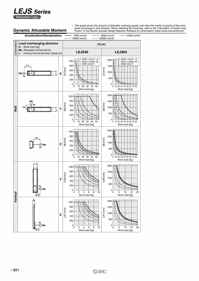
mMe
L10
mMe
L11
0
200
400
600
800
1000
0
500
1000
1500
2000
L7
[mm
]
L7
[mm
]
0 10 40 5020 300 10 40 5020 30 60 70 80
0
200
400
600
800
1000
0
500
1000
1500
2000
L8
[mm
]
L8
[mm
]
0 10 40 5020 300 10 40 5020 30 60 70 80
0
200
400
600
800
1000
0
500
1000
1500
2000
L9
[mm
]
L9
[mm
]
0 10 40 5020 300 10 40 5020 30 60 70 80
0
200
400
600
800
1000
0
500
1000
1500
2000
L10
[mm
]
L10
[mm
]
0 10 155 20
0 10 155 20
0 2 8 104 6
0 2 8 104 60
200
400
600
800
1000
0
500
1000
1500
2000
L11
[mm
]
L11
[mm
]
Work load [kg]Work load [kg]
Work load [kg]Work load [kg]
Work load [kg]Work load [kg]
Work load [kg]Work load [kg]
Work load [kg]Work load [kg]
5000 mm/s2 or less is same as 5000 mm/s2
5000 mm/s2 or less is same as 5000 mm/s2
L7
mMe
mMe
L8
L9
mMe
Orie
ntat
ion Load overhanging direction
m : Work load [kg]Me: Allowable moment [N·m]L : Overhang to the work load center of gravity [mm]
Model
LEJS40 LEJS63
Wal
l
X
Y
Z
Ver
tica
l
Y
Z
Dynamic Allowable Moment* This graph shows the amount of allowable overhang (guide unit) when the center of gravity of the work-
piece overhangs in one direction. When selecting the overhang, refer to the “Calculation of Guide Load Factor” or the Electric Actuator Model Selection Software for confirmation: https://www.smcworld.com
Acceleration/Deceleration 1000 mm/s2 5000 mm/s2
10000 mm/s23000 mm/s2
20000 mm/s2
881
LEJS SeriesMotorless Type
A
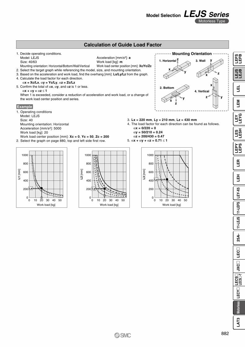
xy
z
x z
y
xy
z
x
z y
0
200
400
600
800
1000
L1
[mm
]
0 10 20 30 40 50
Work load [kg]
Lx
0
200
400
600
800
1000
L2
[mm
]
0 10 20 30 40 50
Work load [kg]
Ly
0
600
800
1000
L3
[mm
]
200
400
0 10 20 30 40 50
Work load [kg]
Lz
Calculation of Guide Load Factor
1. Decide operating conditions.Model: LEJSSize: 40/63Mounting orientation: Horizontal/Bottom/Wall/Vertical
2. Select the target graph while referencing the model, size, and mounting orientation.3. Based on the acceleration and work load, find the overhang [mm]: Lx/Ly/Lz from the graph.4. Calculate the load factor for each direction.
αx = Xc/Lx, αy = Yc/Ly, αz = Zc/Lz5. Confirm the total of αx, αy, and αz is 1 or less.
αx + αy + αz ≤ 1When 1 is exceeded, consider a reduction of acceleration and work load, or a change of the work load center position and series.
1. Operating conditionsModel: LEJSSize: 40Mounting orientation: HorizontalAcceleration [mm/s2]: 5000Work load [kg]: 20Work load center position [mm]: Xc = 0, Yc = 50, Zc = 200
2. Select the graph on page 880, top and left side first row.
Example
Acceleration [mm/s2]: aWork load [kg]: mWork load center position [mm]: Xc/Yc/Zc
Mounting Orientation
1. Horizontal 3. Wall
2. Bottom4. Vertical
3. Lx = 220 mm, Ly = 210 mm, Lz = 430 mm4. The load factor for each direction can be found as follows.
αx = 0/220 = 0αy = 50/210 = 0.24αz = 200/430 = 0.47
5. αx + αy + αz = 0.71 ≤ 1
882
Model Selection LEJS SeriesMotorless Type
LE
FS
LE
FB
LE
LL
EJS
LE
JBL
EM
LE
YL
EY
GL
ES
LE
SH
LE
PY
LE
PS
LE
RL
EH
LEY-
X511
-LEF
S11
-LEJ
S25
A-
Moto
rless
LEC
Y�LE
CS
�LE
CS�-
TJX
C�
LE
C�
LA
T3
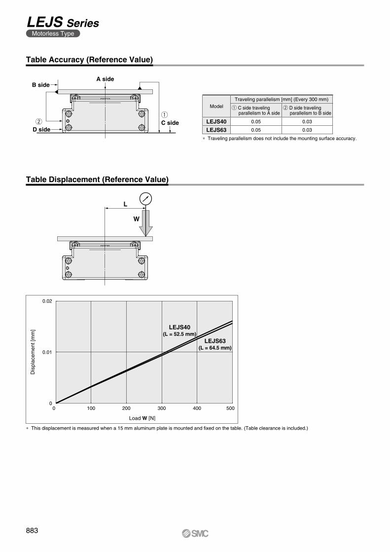
wq
A side
C sideD side
B side
W
L
0.02
0.01
00 100 200 300 400 500
Dis
plac
emen
t [m
m]
Load W [N]
LEJS40(L = 52.5 mm)
LEJS63(L = 64.5 mm)
Table Accuracy (Reference Value)
∗ Traveling parallelism does not include the mounting surface accuracy.
ModelTraveling parallelism [mm] (Every 300 mm)
q C side traveling parallelism to A side
w D side traveling parallelism to B side
LEJS40 0.05 0.03
LEJS63 0.05 0.03
Table Displacement (Reference Value)
∗ This displacement is measured when a 15 mm aluminum plate is mounted and fixed on the table. (Table clearance is included.)
883
LEJS SeriesMotorless Type
884
LE
FS
LE
FB
LE
LL
EJS
LE
JBL
EM
LE
YL
EY
GL
ES
LE
SH
LE
PY
LE
PS
LE
RL
EH
LEY-
X511
-LEF
S11
-LEJ
S25
A-
Moto
rless
LEC
Y�LE
CS
�LE
CS�-
TJX
C�
LE
C�
LA
T3
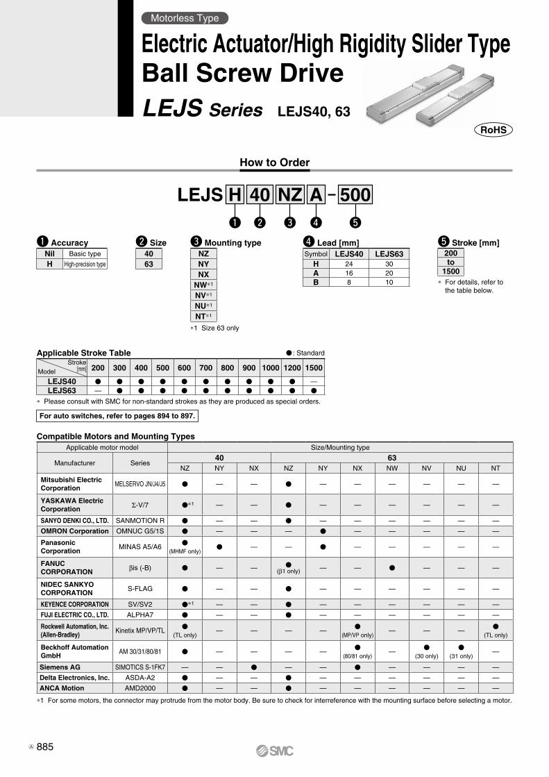
How to Order
t Stroke [mm]e Mounting type
*1 Size 63 only
q Accuracy
* For details, refer to the table below.
40 500w
LEJSe r t
Aq
H NZ
Nil Basic type
H High-precision type
V : Standard
* Please consult with SMC for non-standard strokes as they are produced as special orders.
Applicable Stroke TableStroke
[mm]Model 200 300 400 500 600 700 800 900 1000 1200 1500
LEJS40 V V V V V V V V V V —LEJS63 — V V V V V V V V V V
r Lead [mm]Symbol LEJS40 LEJS63
H 24 30A 16 20B 8 10
200to
1500
w Size4063
Motorless Type
Electric Actuator/High Rigidity Slider TypeBall Screw DriveLEJS Series LEJS40, 63
For auto switches, refer to pages 894 to 897.
NZNYNX
NW*1
NV*1
NU*1
NT*1
Compatible Motors and Mounting TypesApplicable motor model Size/Mounting type
Manufacturer Series40 63
NZ NY NX NZ NY NX NW NV NU NT
Mitsubishi ElectricCorporation
MELSERVO JN/J4/J5 V — — V — — — — — —
YASKAWA Electric Corporation Σ-V/7 V*1 — — V — — — — — —
SANYO DENKI CO., LTD. SANMOTION R V — — V — — — — — —
OMRON Corporation OMNUC G5/1S V — — — V — — — — —
PanasonicCorporation
MINAS A5/A6V
(MHMF only)V — — V — — — — —
FANUCCORPORATION βis (-B) V — — V
(β1 only) — — V — — —
NIDEC SANKYO CORPORATION
S-FLAG V — — V — — — — — —
KEYENCE CORPORATION SV/SV2 V*1 — — V — — — — — —
FUJI ELECTRIC CO., LTD. ALPHA7 V — — V — — — — — —
Rockwell Automation, Inc. (Allen-Bradley)
Kinetix MP/VP/TLV
(TL only)— — — —
V(MP/VP only)
— — —V
(TL only)
Beckhoff Automation GmbH
AM 30/31/80/81 V — — — —V
(80/81 only)—
V(30 only)
V(31 only)
—
Siemens AG SIMOTICS S-1FK7 — — V — — V — — — —
Delta Electronics, Inc. ASDA-A2 V — — V — — — — — —
ANCA Motion AMD2000 V — — V — — — — — —
*1 For some motors, the connector may protrude from the motor body. Be sure to check for interreference with the mounting surface before selecting a motor.
885A
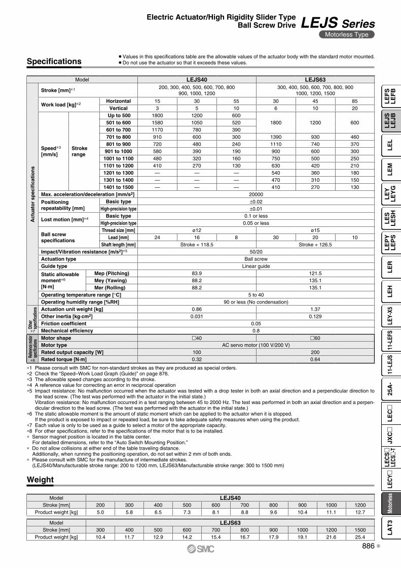
Specifications
Weight
∗1 Please consult with SMC for non-standard strokes as they are produced as special orders.∗2 Check the “Speed–Work Load Graph (Guide)” on page 876.∗3 The allowable speed changes according to the stroke.∗4 A reference value for correcting an error in reciprocal operation∗5 Impact resistance: No malfunction occurred when the actuator was tested with a drop tester in both an axial direction and a perpendicular direction to
the lead screw. (The test was performed with the actuator in the initial state.)Vibration resistance: No malfunction occurred in a test ranging between 45 to 2000 Hz. The test was performed in both an axial direction and a perpen-dicular direction to the lead screw. (The test was performed with the actuator in the initial state.)
∗6 The static allowable moment is the amount of static moment which can be applied to the actuator when it is stopped.If the product is exposed to impact or repeated load, be sure to take adequate safety measures when using the product.
∗7 Each value is only to be used as a guide to select a motor of the appropriate capacity.∗8 For other specifications, refer to the specifications of the motor that is to be installed.∗ Sensor magnet position is located in the table center.
For detailed dimensions, refer to the “Auto Switch Mounting Position.”∗ Do not allow collisions at either end of the table traveling distance.
Additionally, when running the positioning operation, do not set within 2 mm of both ends.∗ Please consult with SMC for the manufacture of intermediate strokes.
(LEJS40/Manufacturable stroke range: 200 to 1200 mm, LEJS63/Manufacturable stroke range: 300 to 1500 mm)
¡Values in this specifications table are the allowable values of the actuator body with the standard motor mounted.¡Do not use the actuator so that it exceeds these values.
Model LEJS40 LEJS63
Act
uat
or
spec
ifica
tio
ns
Stroke [mm]∗1 200, 300, 400, 500, 600, 700, 800900, 1000, 1200
300, 400, 500, 600, 700, 800, 9001000, 1200, 1500
Work load [kg]∗2Horizontal 15 30 55 30 45 85
Vertical 3 5 10 6 10 20
Speed∗3
[mm/s]Strokerange
Up to 500 1800 1200 6001800 1200 600501 to 600 1580 1050 520
601 to 700 1170 780 390701 to 800 910 600 300 1390 930 460801 to 900 720 480 240 1110 740 370901 to 1000 580 390 190 900 600 300
1001 to 1100 480 320 160 750 500 2501101 to 1200 410 270 130 630 420 2101201 to 1300 — — — 540 360 1801301 to 1400 — — — 470 310 1501401 to 1500 — — — 410 270 130
Max. acceleration/deceleration [mm/s2] 20000
Positioning repeatability [mm]
Basic type ±0.02High-precision type ±0.01
Lost motion [mm]∗4Basic type 0.1 or less
High-precision type 0.05 or less
Ball screw specifications
Thread size [mm] ø12 ø15Lead [mm] 24 16 8 30 20 10
Shaft length [mm] Stroke + 118.5 Stroke + 126.5Impact/Vibration resistance [m/s2]∗5 50/20Actuation type Ball screwGuide type Linear guide
Static allowable moment∗6
[N·m]
Mep (Pitching) 83.9 121.5Mey (Yawing) 88.2 135.1Mer (Rolling) 88.2 135.1
Operating temperature range [°C] 5 to 40Operating humidity range [%RH] 90 or less (No condensation)
Othe
r sp
ecific
ation
s Actuation unit weight [kg] 0.86 1.37Other inertia [kg·cm2] 0.031 0.129Friction coefficient 0.05Mechanical efficiency 0.8
Refer
ence
moto
rsp
ecific
ation
s Motor shape 40 60Motor type AC servo motor (100 V/200 V)Rated output capacity [W] 100 200Rated torque [N·m] 0.32 0.64
Model LEJS40Stroke [mm] 200 300 400 500 600 700 800 900 1000 1200
Product weight [kg] 5.0 5.8 6.5 7.3 8.1 8.8 9.6 10.4 11.1 12.7
Model LEJS63Stroke [mm] 300 400 500 600 700 800 900 1000 1200 1500
Product weight [kg] 10.4 11.7 12.9 14.2 15.4 16.7 17.9 19.1 21.6 25.4
∗7
∗8
886
Electric Actuator/High Rigidity Slider TypeBall Screw Drive LEJS Series
Motorless Type
LE
FS
LE
FB
LE
LL
EJS
LE
JBL
EM
LE
YL
EY
GL
ES
LE
SH
LE
PY
LE
PS
LE
RL
EH
LEY-
X511
-LEF
S11
-LEJ
S25
A-
Moto
rless
LEC
Y�LE
CS
�LE
CS�-
TJX
C�
LE
C�
LA
T3
B
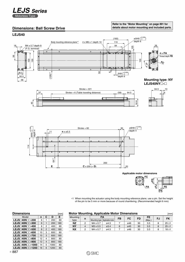
56
36.5
50.5
58
130
100
18
n x FAthread depth FB
26
100
45°
FC
(160)
110
84
94 6
105
45
(58) 64.537
50.8
114
30
11
20
200
E
64.5 10
6
(128
)∗1
Stroke + 6 (Table traveling distance)
Stroke + 221
M4 x 0.7 depth 8(F.G. terminal)
4 x M6 x 1 depth 10
ø5H9 ( )depth 6
+0.030 0
Body mounting reference plane∗1
ø6H9 ( )depth 4
+0.030 0Stroke + 60
n x ø5.5
64∗1
C x 200 (= D)
6H9
(
)
dept
h 4+0.
030
0
5H9 ( )depth 6
+0.030 0
Applicable motor dimensions
øF
DøF
J
FKFE
FC
FA
Refer to the “Motor Mounting” on page 891 for details about motor mounting and included parts.Dimensions: Ball Screw Drive
LEJS40
Dimensions [mm]
∗1 When mounting the actuator using the body mounting reference plane, use a pin. Set the height of the pin to be 5 mm or more because of round chamfering. (Recommended height 6 mm)
Model n C D ELEJS40N-200 6 1 200 80LEJS40N-300 6 1 200 180LEJS40N-400 8 2 400 80LEJS40N-500 8 2 400 180LEJS40N-600 10 3 600 80LEJS40N-700 10 3 600 180LEJS40N-800 12 4 800 80LEJS40N-900 12 4 800 180LEJS40N-1000 14 5 1000 80LEJS40N-1200 16 6 1200 80
Mounting type: NYLEJS40NYl-l
Motor Mounting, Applicable Motor Dimensions [mm]
Mounting type n FA FB FC FD FE
(Max.)FJ FK
Mounting type Applicable motorNZ 2 M4 x 0.7 ø4.5 7 ø46 30 3.5 8 25 ±1NY 4 M3 x 0.5 ø3.4 6 ø45 30 3.5 8 25 ±1NX 2 M4 x 0.7 ø4.5 7 ø46 30 3.5 8 18 ±1
887
LEJS SeriesMotorless Type
A
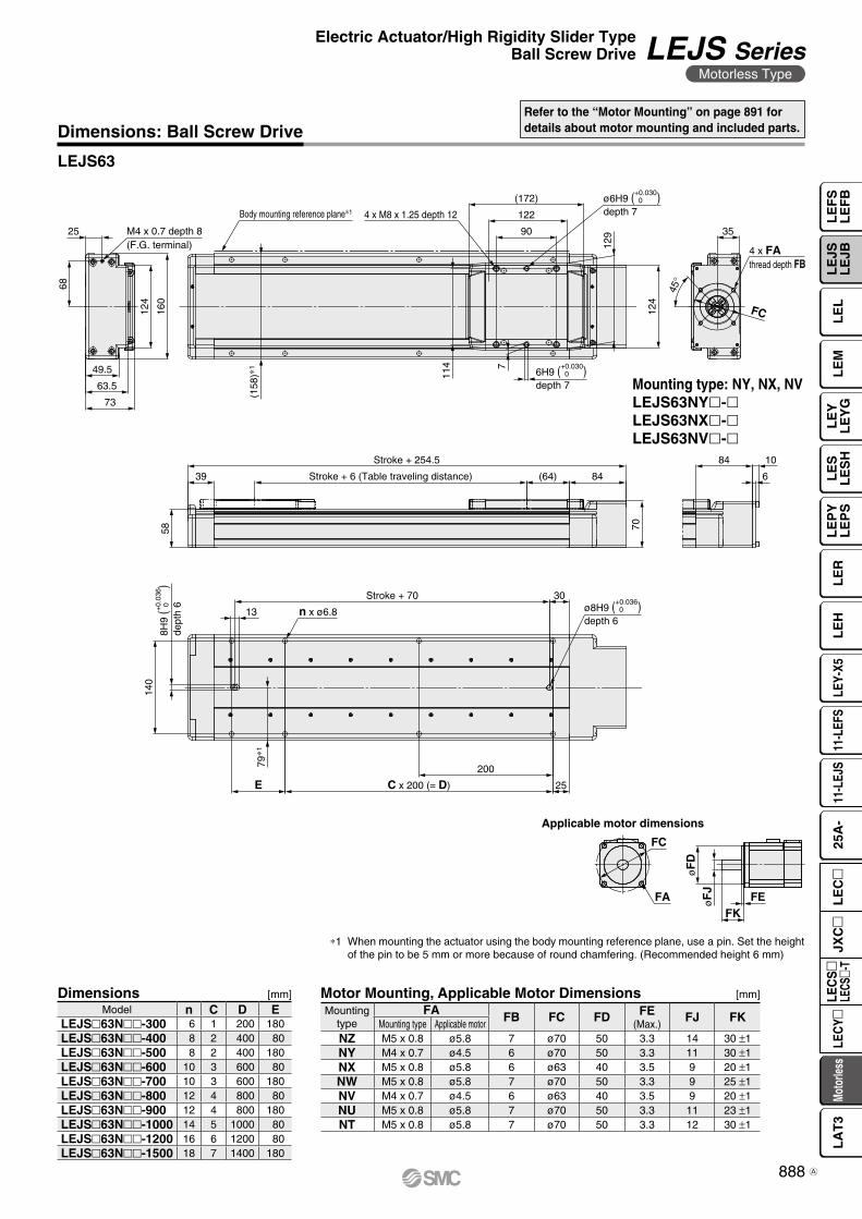
25
45°
FC160
124
68
49.5
63.5
73
(172)
122
90
124
35
129
114 7
(64) 8439
7058
84 10
6
140
13
30
200
E 25
n x ø6.8
Stroke + 70
C x 200 (= D)
79∗1
ø8H9 ( )depth 6
+0.036 0
8H9
(
)
dept
h 6+0.
036
0
Stroke + 254.5
Stroke + 6 (Table traveling distance)
M4 x 0.7 depth 8(F.G. terminal)
Body mounting reference plane∗1 4 x M8 x 1.25 depth 12
(158
)∗1
ø6H9 ( )depth 7
+0.030 0
6H9 ( )depth 7
+0.030 0
4 x FAthread depth FB
Applicable motor dimensions
øF
DøF
J
FKFE
FC
FA
Dimensions: Ball Screw Drive
LEJS63
Refer to the “Motor Mounting” on page 891 for details about motor mounting and included parts.
Mounting type: NY, NX, NVLEJS63NYl-lLEJS63NXl-lLEJS63NVl-l
Dimensions [mm]Model n C D E
LEJS63N-300 6 1 200 180LEJS63N-400 8 2 400 80LEJS63N-500 8 2 400 180LEJS63N-600 10 3 600 80LEJS63N-700 10 3 600 180LEJS63N-800 12 4 800 80LEJS63N-900 12 4 800 180LEJS63N-1000 14 5 1000 80LEJS63N-1200 16 6 1200 80LEJS63N-1500 18 7 1400 180
Motor Mounting, Applicable Motor Dimensions [mm]
Mounting type
FA FB FC FD FE(Max.)
FJ FKMounting type Applicable motor
NZ M5 x 0.8 ø5.8 7 ø70 50 3.3 14 30 ±1NY M4 x 0.7 ø4.5 6 ø70 50 3.3 11 30 ±1NX M5 x 0.8 ø5.8 6 ø63 40 3.5 9 20 ±1NW M5 x 0.8 ø5.8 7 ø70 50 3.3 9 25 ±1NV M4 x 0.7 ø4.5 6 ø63 40 3.5 9 20 ±1NU M5 x 0.8 ø5.8 7 ø70 50 3.3 11 23 ±1NT M5 x 0.8 ø5.8 7 ø70 50 3.3 12 30 ±1
∗1 When mounting the actuator using the body mounting reference plane, use a pin. Set the height of the pin to be 5 mm or more because of round chamfering. (Recommended height 6 mm)
888
Electric Actuator/High Rigidity Slider TypeBall Screw Drive LEJS Series
Motorless Type
LE
FS
LE
FB
LE
LL
EJS
LE
JBL
EM
LE
YL
EY
GL
ES
LE
SH
LE
PY
LE
PS
LE
RL
EH
LEY-
X511
-LEF
S11
-LEJ
S25
A-
Moto
rless
LEC
Y�LE
CS
�LE
CS�-
TJX
C�
LE
C�
LA
T3
A
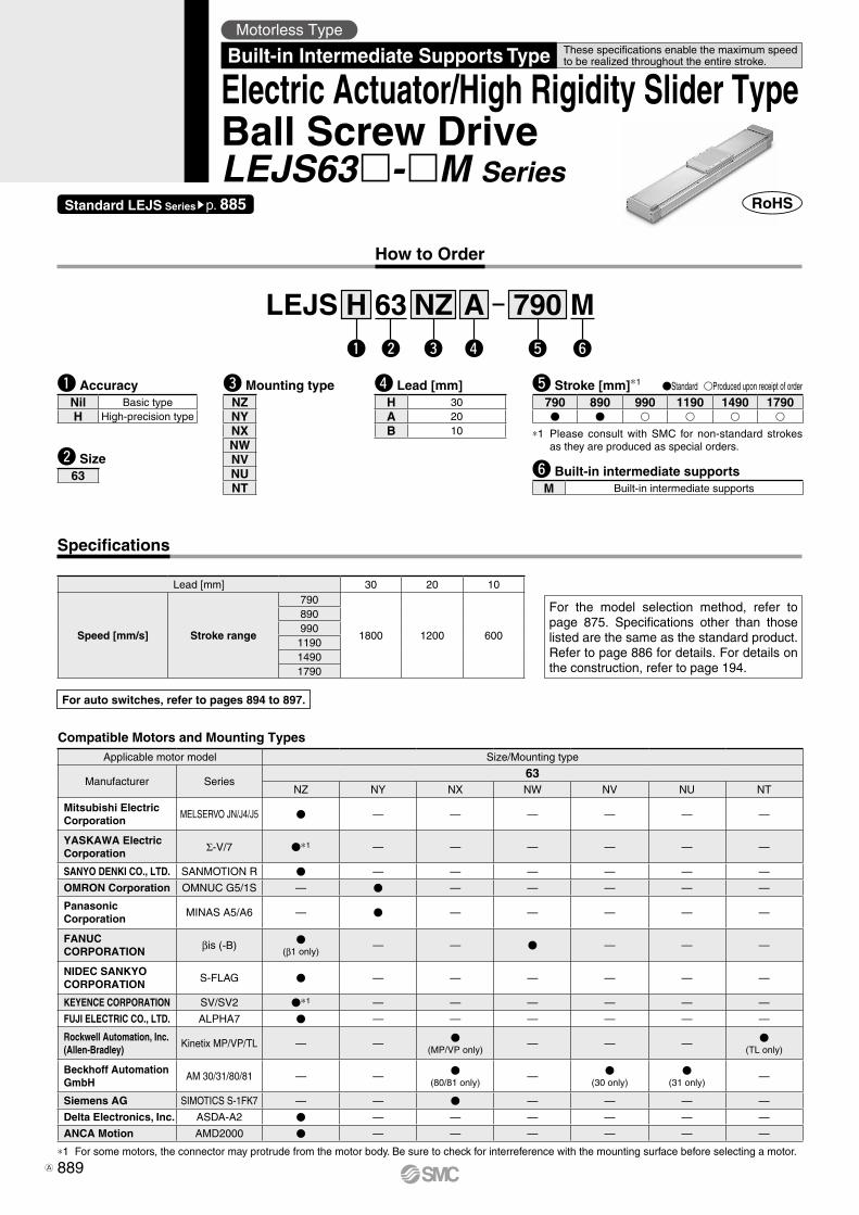
How to Order
For auto switches, refer to pages 894 to 897.
Motorless TypeThese specifications enable the maximum speed to be realized throughout the entire stroke.Built-in Intermediate Supports Type
Electric Actuator/High Rigidity Slider TypeBall Screw DriveLEJS63-M Series
Lead [mm] 30 20 10
Speed [mm/s] Stroke range
790
1800 1200 600
890990
119014901790
Specifications
For the model selection method, refer to page 875. Specifications other than those listed are the same as the standard product. Refer to page 886 for details. For details on the construction, refer to page 194.
w e r t yq
w Size63
q AccuracyNil Basic typeH High-precision type
y Built-in intermediate supportsM Built-in intermediate supports
r Lead [mm]H 30A 20B 10
t Stroke [mm]*1 Standard Produced upon receipt of order
790 890 990 1190 1490 1790
*1 Please consult with SMC for non-standard strokes as they are produced as special orders.
LEJS H 63 NZ A 790 M
Standard LEJS Seriessp. 885
e Mounting typeNZNYNXNWNVNUNT
Compatible Motors and Mounting TypesApplicable motor model Size/Mounting type
Manufacturer Series63
NZ NY NX NW NV NU NT
Mitsubishi ElectricCorporation
MELSERVO JN/J4/J5 — — — — — —
YASKAWA Electric Corporation Σ-V/7 *1 — — — — — —
SANYO DENKI CO., LTD. SANMOTION R — — — — — —
OMRON Corporation OMNUC G5/1S — — — — — —
Panasonic Corporation
MINAS A5/A6 — — — — — —
FANUC CORPORATION βis (-B)
(β1 only)— — — — —
NIDEC SANKYO CORPORATION
S-FLAG — — — — — —
KEYENCE CORPORATION SV/SV2 *1 — — — — — —
FUJI ELECTRIC CO., LTD. ALPHA7 — — — — — —
Rockwell Automation, Inc. (Allen-Bradley)
Kinetix MP/VP/TL — — (MP/VP only)
— — — (TL only)
Beckhoff Automation GmbH
AM 30/31/80/81 — — (80/81 only)
— (30 only)
(31 only)
—
Siemens AG SIMOTICS S-1FK7 — — — — — —
Delta Electronics, Inc. ASDA-A2 — — — — — —
ANCA Motion AMD2000 — — — — — —
*1 For some motors, the connector may protrude from the motor body. Be sure to check for interreference with the mounting surface before selecting a motor.
889A
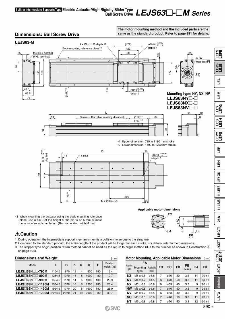
25 M4 x 0.7 depth 8(F.G. terminal) 4 x FA
thread depth FB
45°
FC
Body mounting reference plane∗3
4 x M8 x 1.25 depth 1216
0
124
68
49.5
63.5
73
(172)
122
90
124
35
129
114 7
LStroke + 10 (Table traveling distance) (117)∗1
(167)∗28439
7058
84 10
6
140
n x ø6.8
B13
30
200
C x 200 (= D)E 25
(158
)∗3
79∗3
+0.030 0ø6H9 ( )
depth 7
+0.036 0ø8H9 ( )
depth 6
+0.030 06H9 ( )
depth 7
+0.
036
08H
9 (
) de
pth
6
Applicable motor dimensions
øF
D
FC
FAFK
FEøF
J
Electric Actuator/High Rigidity Slider TypeBall Screw Drive
Built-in Intermediate Supports Type LEJS63-M Series
LEJS63-M
Dimensions: Ball Screw Drive
*3 When mounting the actuator using the body mounting reference plane, use a pin. Set the height of the pin to be 5 mm or more because of round chamfering. (Recommended height 6 mm)
Mounting type: NY, NX, NVLEJS63NY-LEJS63NX-LEJS63NV-
The motor mounting method and the included parts are the same as the standard product. Refer to page 891 for details.
Dimensions and Weight [mm]
Model L B n C D E Product weight [kg]
LEJS63N-790M 1154.5 970 12 4 800 180 18.4
LEJS63N-890M 1254.5 1070 14 5 1000 80 19.7
LEJS63N-990M 1354.5 1170 14 5 1000 180 20.9
LEJS63N-1190M 1554.5 1370 16 6 1200 180 23.4
LEJS63N-1490M 1954.5 1770 20 8 1600 180 28.9
LEJS63N-1790M 2254.5 2070 24 10 2000 80 32.7
*1 Upper dimension: 790 to 1190 mm stroke*2 Lower dimension: 1490 to 1790 mm stroke
1. During operation, the intermediate support mechanism emits a collision noise due to the structure.2. Compared to the standard product, the entire length of the product will be longer for each stroke. For details, refer to the dimensions.3. The stopper type origin position return method cannot be used as the return to origin method (due to the bumper as shown in Construction r
on page 194).
Caution
Motor Mounting, Applicable Motor Dimensions [mm]
Mounting type
FAFB FC FD FE
(Max.)FJ FKMounting
typeApplicable
motor
NZ M5 x 0.8 ø5.8 7 ø70 50 3.3 14 30 ±1
NY M4 x 0.7 ø4.5 6 ø70 50 3.3 11 30 ±1
NX M5 x 0.8 ø5.8 6 ø63 40 3.5 9 20 ±1
NW M5 x 0.8 ø5.8 7 ø70 50 3.3 9 25 ±1
NV M4 x 0.7 ø4.5 6 ø63 40 3.5 9 20 ±1
NU M5 x 0.8 ø5.8 7 ø70 50 3.3 11 23 ±1
NT M5 x 0.8 ø5.8 7 ø70 50 3.3 12 30 ±1
890
LE
FS
LE
FB
LE
LL
EJS
LE
JBL
EM
LE
YL
EY
GL
ES
LE
SH
LE
PY
LE
PS
LE
RL
EH
LEY-
X511
-LEF
S11
-LEJ
S25
A-
Moto
rless
LEC
Y�LE
CS
�LE
CS�-
TJX
C�
LE
C�
LA
T3
A
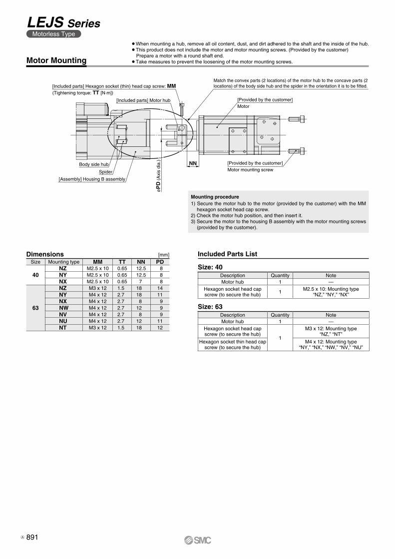
NN
[Included parts] Hexagon socket (thin) head cap screw: MM(Tightening torque: TT [N·m])
[Included parts] Motor hub
Body side hub
Spider
[Provided by the customer]Motor
[Assembly] Housing B assembly
øP
D (
Axi
s di
a.)
[Provided by the customer]Motor mounting screw
Match the convex parts (2 locations) of the motor hub to the concave parts (2 locations) of the body side hub and the spider in the orientation it is to be fitted.
¡When mounting a hub, remove all oil content, dust, and dirt adhered to the shaft and the inside of the hub.¡This product does not include the motor and motor mounting screws. (Provided by the customer)
Prepare a motor with a round shaft end.¡Take measures to prevent the loosening of the motor mounting screws.Motor Mounting
Dimensions [mm]
Size: 40
Size: 63
Included Parts List
Mounting procedure1) Secure the motor hub to the motor (provided by the customer) with the MM
hexagon socket head cap screw.2) Check the motor hub position, and then insert it.3) Secure the motor to the housing B assembly with the motor mounting screws
(provided by the customer).
Description Quantity NoteMotor hub 1 —
Hexagon socket head cap screw (to secure the hub)
1
M3 x 12: Mounting type “NZ,” “NT”
Hexagon socket thin head cap screw (to secure the hub)
M4 x 12: Mounting type“NY,” “NX,” “NW,” “NV,” “NU”
Size Mounting type MM TT NN PD
40NZ M2.5 x 10 0.65 12.5 8NY M2.5 x 10 0.65 12.5 8NX M2.5 x 10 0.65 7 8
63
NZ M3 x 12 1.5 18 14NY M4 x 12 2.7 18 11NX M4 x 12 2.7 8 9NW M4 x 12 2.7 12 9NV M4 x 12 2.7 8 9NU M4 x 12 2.7 12 11NT M3 x 12 1.5 18 12
Description Quantity NoteMotor hub 1 —
Hexagon socket head cap screw (to secure the hub) 1 M2.5 x 10: Mounting type
“NZ,” “NY,” “NX”
891
LEJS SeriesMotorless Type
A
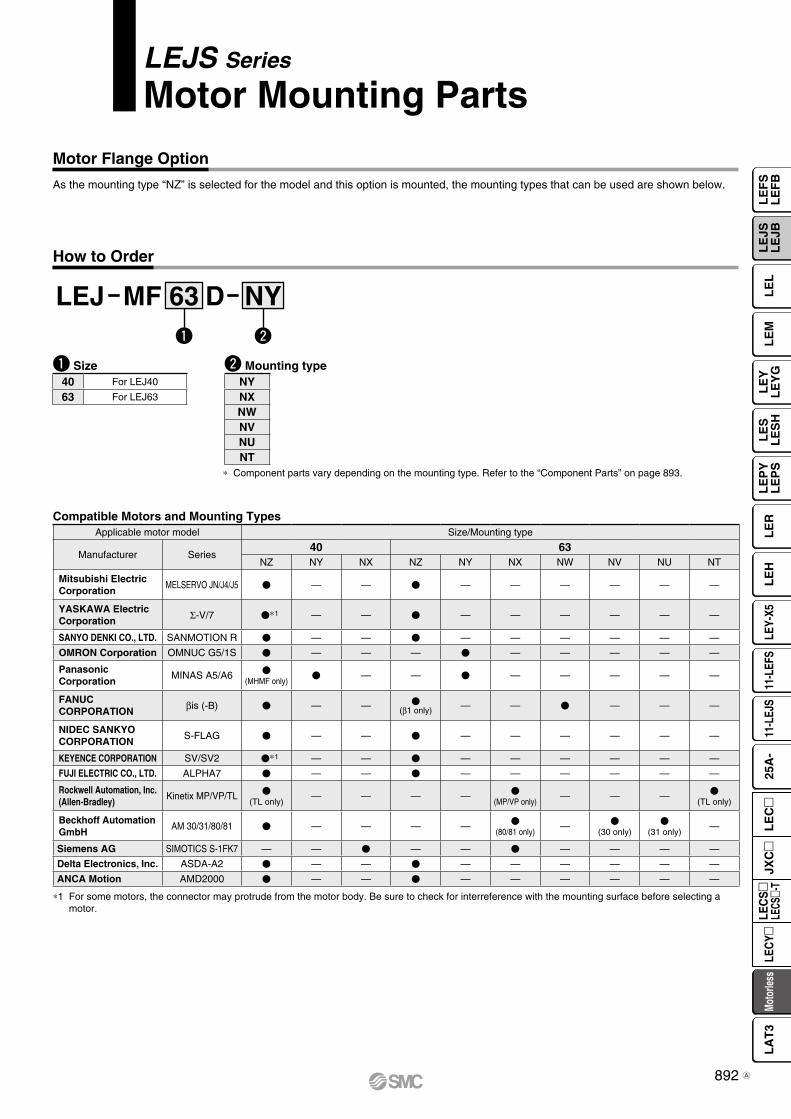
LEJS Series
Motor Mounting Parts
q Size
* Component parts vary depending on the mounting type. Refer to the “Component Parts” on page 893.
w Mounting type40 For LEJ40
63 For LEJ63
NYNXNWNVNUNT
Compatible Motors and Mounting Types
LEJ MF D NY63q w
Motor Flange Option
As the mounting type “NZ” is selected for the model and this option is mounted, the mounting types that can be used are shown below.
How to Order
Applicable motor model Size/Mounting type
Manufacturer Series40 63
NZ NY NX NZ NY NX NW NV NU NT
Mitsubishi ElectricCorporation
MELSERVO JN/J4/J5 V — — V — — — — — —
YASKAWA Electric Corporation Σ-V/7 V*1 — — V — — — — — —
SANYO DENKI CO., LTD. SANMOTION R V — — V — — — — — —
OMRON Corporation OMNUC G5/1S V — — — V — — — — —
PanasonicCorporation
MINAS A5/A6 V(MHMF only)
V — — V — — — — —
FANUCCORPORATION βis (-B) V — — V
(β1 only) — — V — — —
NIDEC SANKYO CORPORATION
S-FLAG V — — V — — — — — —
KEYENCE CORPORATION SV/SV2 V*1 — — V — — — — — —
FUJI ELECTRIC CO., LTD. ALPHA7 V — — V — — — — — —
Rockwell Automation, Inc. (Allen-Bradley)
Kinetix MP/VP/TL V(TL only)
— — — — V(MP/VP only)
— — — V(TL only)
Beckhoff Automation GmbH
AM 30/31/80/81 V — — — — V(80/81 only)
— V(30 only)
V(31 only)
—
Siemens AG SIMOTICS S-1FK7 — — V — — V — — — —
Delta Electronics, Inc. ASDA-A2 V — — V — — — — — —
ANCA Motion AMD2000 V — — V — — — — — —
*1 For some motors, the connector may protrude from the motor body. Be sure to check for interreference with the mounting surface before selecting a motor.
892
LE
FS
LE
FB
LE
LL
EJS
LE
JBL
EM
LE
YL
EY
GL
ES
LE
SH
LE
PY
LE
PS
LE
RL
EH
LEY-
X511
-LEF
S11
-LEJ
S25
A-
Moto
rless
LEC
Y�LE
CS
�LE
CS�-
TJX
C�
LE
C�
LA
T3
A
Actuator
Hexagon socket head cap screw: M1(Tightening torque: T1 [N·m])
FP (Mounting distance)øP
D (
I.D.)
Hexagon socket head cap screw: M2(Tightening torque: T2 [N·m])t re
Motor
FG4 x FA, thread depth FB
FC
FH
qw
Motor mounting surface
øF
D
FFFE
q w
Dimensions: Motor Flange Option
Motor plate details
Component PartsSize: 40
No. Description
Quantity
Mounting type
NY NX1 Motor plate 1 —
2 Ring 1 —
3 Hub (Motor side) 1 1
4 Hexagon socket thin head cap screw 1 1
5 Hexagon socket head cap screw 4 —
Size: 63
No. Description
Quantity
Mounting type
NY NX NW NV NU NT1 Motor plate 1 1 — 1 — —
2 Ring 1 1 — 1 — —
3 Hub (Motor side) 1 1 1 1 1 1
4 Hexagon socket thin head cap screw 1 1 1 1 1 1
5 Hexagon socket head cap screw 4 4 — 4 — —
Dimensions [mm]
Size Mounting type FA FB FC FD FE FF FG FH M1 T1 M2 T2 PD FP
40NY M3 x 0.5 6 ø45 30 3.5 6 99 49 M4 x 12 2.7 M2.5 x 10 0.65 8 12.5
NX — — — — — — — — — — M2.5 x 10 0.65 8 7
63
NY M4 x 0.7 6 ø70 50 3.5 6 123 68 M4 x 12 2.7 M4 x 12 2.7 11 18
NX M5 x 0.8 6 ø63 40 3.5 6 123 68 M4 x 12 2.7 M4 x 12 2.7 9 8
NW — — — — — — — — — — M4 x 12 2.7 9 12
NV M4 x 0.7 6 ø63 40 3.5 6 123 68 M4 x 12 2.7 M4 x 12 2.7 9 8
NU — — — — — — — — — — M4 x 12 2.7 11 12
NT — — — — — — — — — — M3 x 12 1.5 12 18
893
LEJS SeriesMotorless Type
A
ø5 to ø6
Flat head watchmaker's screwdriver(Not an accessory)
(C)
B (Table center)
A
LEJS Series
Auto Switch Mounting
Auto Switch Mounting Position
Auto Switch Mounting
Auto Switch Mounting ScrewTightening Torque [N·m]
When mounting the auto switches, they should be inserted into the actuator’s auto switch mounting groove as shown in the drawing below. After setting in the mounting position, use a flat head watchmaker’s screwdriver to tighten the auto switch mounting screw that is included.
∗ When tightening the auto switch mounting screw (included with auto switch), use a watchmaker’s screwdriver with a handle diameter of about 5 to 6 mm.
∗ Since the operating range is provided as a guideline including hysteresis, it cannot be guaranteed (assuming approximately ±30% dispersion). It may change substantially depending on the ambient environment.
[mm]
Model Size A B C Operating range
LEJS40 77 80 160 5.5
63 83 86 172 7.0
Auto switch model Tightening torqueD-M9l(V)D-M9lW(V)
0.10 to 0.15
894
LE
FS
LE
FB
LE
LL
EJS
LE
JBL
EM
LE
YL
EY
GL
ES
LE
SH
LE
PY
LE
PS
LE
RL
EH
LEY-
X511
-LEF
S11
-LEJ
S25
A-
Moto
rless
LEC
Y�LE
CS
�LE
CS�-
TJX
C�
LE
C�
LA
T3
PrecautionsCaution
Fix the auto switch with the existing screw installed on the auto switch body. The auto switch may be damaged if a screw other than the one supplied is used.
Weight [g]
Grommet
∗ Refer to page 996 for solid state auto switch common specifications.∗ Refer to page 996 for lead wire lengths.
DimensionsD-M9m D-M9mV
P 2-wire load current is reduced (2.5 to 40 mA).
P Using flexible cable as standard spec.
[mm]
Oilproof Heavy-duty Lead Wire Specifications
Solid State Auto SwitchDirect Mounting TypeD-M9N(V)/D-M9P(V)/D-M9B(V)
Auto Switch SpecificationsPLC: Programmable Logic Controller
Refer to the SMC website for details on products that are compliant with international standards.
RoHS
Most sensitive position
ø2.
6
2.6
3.95
2.8
6
22.8
Mounting screw M2.5 x 4 L
Slotted set screw (flat point)
Indicator light
19.5
15.9
7.5
9.5
4
2.6
0.3
ø2.6
Indicator light
Slotted set screw2
Most sensitive position6
2.8 4.6
500
(100
0) (
3000
) (5
000)
Mounting screw M2.5 x 4 L
D-M9l, D-M9lV (With indicator light)Auto switch model D-M9N D-M9NV D-M9P D-M9PV D-M9B D-M9BVElectrical entry direction In-line Perpendicular In-line Perpendicular In-line Perpendicular
Wiring type 3-wire 2-wire
Output type NPN PNP —
Applicable load IC circuit, Relay, PLC 24 VDC relay, PLC
Power supply voltage 5, 12, 24 VDC (4.5 to 28 V) —
Current consumption 10 mA or less —
Load voltage 28 VDC or less — 24 VDC (10 to 28 VDC)
Load current 40 mA or less 2.5 to 40 mA
Internal voltage drop 0.8 V or less at 10 mA (2 V or less at 40 mA) 4 V or less
Leakage current 100 mA or less at 24 VDC 0.8 mA or less
Indicator light Red LED illuminates when turned ON.
Standard CE marking, RoHS
Auto switch model D-M9N(V) D-M9P(V) D-M9B(V)Sheath Outside diameter [mm] 2.6
InsulatorNumber of cores 3 cores (Brown/Blue/Black) 2 cores (Brown/Blue)
Outside diameter [mm] 0.88
ConductorEffective area [mm2] 0.15
Strand diameter [mm] 0.05
Minimum bending radius [mm] (Reference values) 17
Auto switch model D-M9N(V) D-M9P(V) D-M9B(V)
Lead wire length
0.5 m (Nil) 8 7
1 m (M) 14 13
3 m (L) 41 38
5 m (Z) 68 63
895
PrecautionsCaution
Fix the auto switch with the existing screw installed on the auto switch body. The auto switch may be damaged if a screw other than the one supplied is used.
Weight [g]
∗ Refer to page 996 for solid state auto switch common specifications.∗ Refer to page 996 for lead wire lengths.
DimensionsD-M9mE D-M9mEV
[mm]
Oilproof Heavy-duty Lead Wire Specifications
Normally Closed Solid State Auto SwitchDirect Mounting TypeD-M9NE(V)/D-M9PE(V)/D-M9BE(V)
Auto Switch SpecificationsPLC: Programmable Logic Controller
Refer to the SMC website for details on products that are compliant with international standards.
∗1 The 1 m and 5 m options are produced upon receipt of order.
Grommet
P Output signal turns on when no magnetic force is detected.
P Can be used for the actuator adopted by the solid state auto switch D-M9 series (excluding special order products)
RoHS
Most sensitive position
ø2.
6
2.6
3.95
2.8
6
22.8
Mounting screw M2.5 x 4 L
Slotted set screw (flat point)
Indicator light
19.5
15.9
7.5
9.5
4
2.6
0.3
ø2.6
Indicator light
Slotted set screw2
Most sensitive position6
2.8
4.6
500
(100
0) (
3000
) (5
000)
Mounting screw M2.5 x 4 L
D-M9lE, D-M9lEV (With indicator light)Auto switch model D-M9NE D-M9NEV D-M9PE D-M9PEV D-M9BE D-M9BEVElectrical entry direction In-line Perpendicular In-line Perpendicular In-line Perpendicular
Wiring type 3-wire 2-wire
Output type NPN PNP —
Applicable load IC circuit, Relay, PLC 24 VDC relay, PLC
Power supply voltage 5, 12, 24 VDC (4.5 to 28 V) —
Current consumption 10 mA or less —
Load voltage 28 VDC or less — 24 VDC (10 to 28 VDC)
Load current 40 mA or less 2.5 to 40 mA
Internal voltage drop 0.8 V or less at 10 mA (2 V or less at 40 mA) 4 V or less
Leakage current 100 mA or less at 24 VDC 0.8 mA or less
Indicator light Red LED illuminates when turned ON.
Standard CE marking, RoHS
Auto switch model D-M9NE(V) D-M9PE(V) D-M9BE(V)Sheath Outside diameter [mm] 2.6
InsulatorNumber of cores 3 cores (Brown/Blue/Black) 2 cores (Brown/Blue)
Outside diameter [mm] 0.88
ConductorEffective area [mm2] 0.15
Strand diameter [mm] 0.05
Minimum bending radius [mm] (Reference values) 17
Auto switch model D-M9NE(V) D-M9PE(V) D-M9BE(V)
Lead wire length
0.5 m (Nil) 8 7
1 m (M)∗1 14 13
3 m (L) 41 38
5 m (Z)∗1 68 63
896
LE
FS
LE
FB
LE
LL
EJS
LE
JBL
EM
LE
YL
EY
GL
ES
LE
SH
LE
PY
LE
PS
LE
RL
EH
LEY-
X511
-LEF
S11
-LEJ
S25
A-
Moto
rless
LEC
Y�LE
CS
�LE
CS�-
TJX
C�
LE
C�
LA
T3
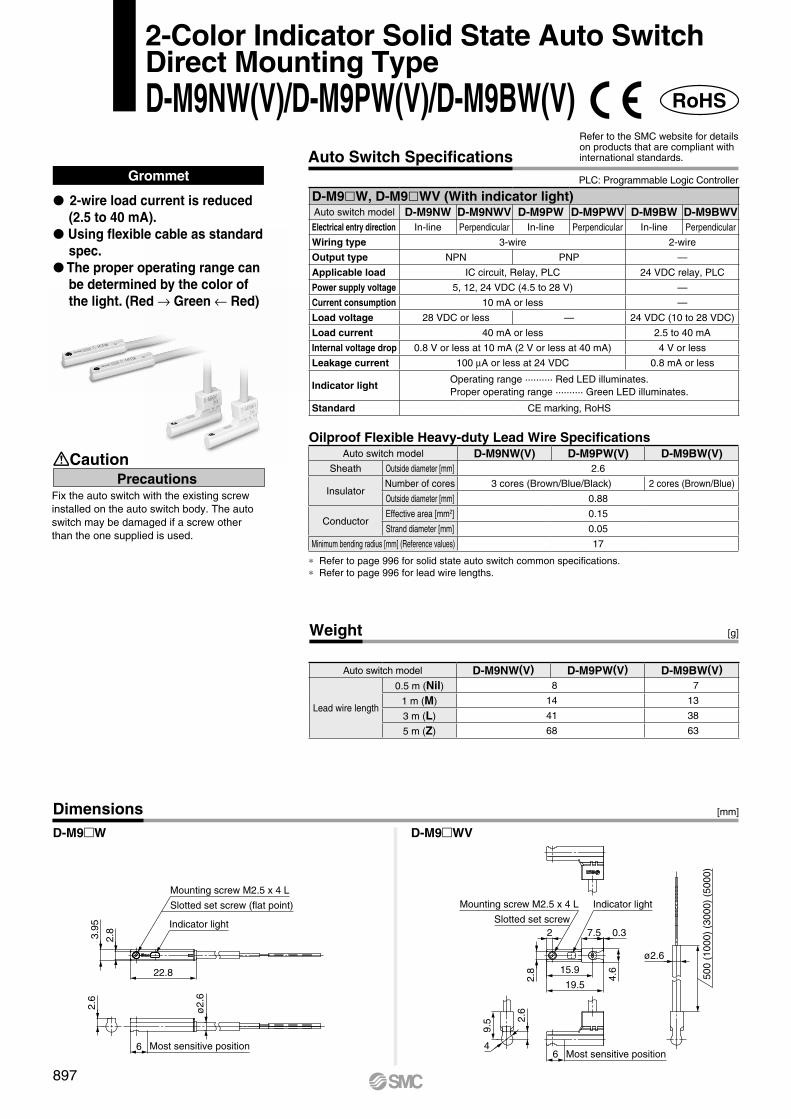
Weight [g]
[mm]Dimensions
Grommet
∗ Refer to page 996 for solid state auto switch common specifications.∗ Refer to page 996 for lead wire lengths.
P 2-wire load current is reduced (2.5 to 40 mA).
P Using flexible cable as standard spec.
P The proper operating range can be determined by the color of the light. (Red → Green ← Red)
D-M9mW D-M9mWV
Oilproof Flexible Heavy-duty Lead Wire Specifications
2-Color Indicator Solid State Auto SwitchDirect Mounting TypeD-M9NW(V)/D-M9PW(V)/D-M9BW(V)
PrecautionsCaution
Fix the auto switch with the existing screw installed on the auto switch body. The auto switch may be damaged if a screw other than the one supplied is used.
Auto Switch SpecificationsRefer to the SMC website for details on products that are compliant with international standards.
PLC: Programmable Logic Controller
RoHS
6 Most sensitive position
2.6
ø2.
6
22.8
Indicator light
3.95
2.8
Slotted set screw (flat point)
Mounting screw M2.5 x 4 L
500
(100
0) (
3000
) (5
000)
Indicator light
ø2.6
4.6
0.37.5
Mounting screw M2.5 x 4 L
Slotted set screw
2.8
9.5 2.
6
4Most sensitive position6
19.5
15.9
2
D-M9lW, D-M9lWV (With indicator light)Auto switch model D-M9NW D-M9NWV D-M9PW D-M9PWV D-M9BW D-M9BWVElectrical entry direction In-line Perpendicular In-line Perpendicular In-line Perpendicular
Wiring type 3-wire 2-wire
Output type NPN PNP —
Applicable load IC circuit, Relay, PLC 24 VDC relay, PLC
Power supply voltage 5, 12, 24 VDC (4.5 to 28 V) —
Current consumption 10 mA or less —
Load voltage 28 VDC or less — 24 VDC (10 to 28 VDC)
Load current 40 mA or less 2.5 to 40 mA
Internal voltage drop 0.8 V or less at 10 mA (2 V or less at 40 mA) 4 V or less
Leakage current 100 mA or less at 24 VDC 0.8 mA or less
Indicator lightOperating range .......... Red LED illuminates.Proper operating range .......... Green LED illuminates.
Standard CE marking, RoHS
Auto switch model D-M9NW(V) D-M9PW(V) D-M9BW(V)Sheath Outside diameter [mm] 2.6
InsulatorNumber of cores 3 cores (Brown/Blue/Black) 2 cores (Brown/Blue)
Outside diameter [mm] 0.88
ConductorEffective area [mm2] 0.15
Strand diameter [mm] 0.05
Minimum bending radius [mm] (Reference values) 17
Auto switch model D-M9NW(V) D-M9PW(V) D-M9BW(V)
Lead wire length
0.5 m (Nil) 8 7
1 m (M) 14 13
3 m (L) 41 38
5 m (Z) 68 63
897
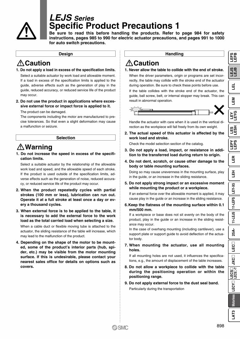
Design Handling
Caution Caution1. Do not apply a load in excess of the specification limits.
Select a suitable actuator by work load and allowable moment. If a load in excess of the specification limits is applied to the guide, adverse effects such as the generation of play in the guide, reduced accuracy, or reduced service life of the product may occur.
2. Do not use the product in applications where excessive external force or impact force is applied to it.The product can be damaged.The components including the motor are manufactured to pre-cise tolerances. So that even a slight deformation may cause a malfunction or seizure.
WarningSelection
1. Do not increase the speed in excess of the specification limits.Select a suitable actuator by the relationship of the allowable work load and speed, and the allowable speed of each stroke. If the product is used outside of the specification limits, ad-verse effects such as the generation of noise, reduced accura-cy, or reduced service life of the product may occur.
2. When the product repeatedly cycles with partial strokes (100 mm or less), lubrication can run out. Operate it at a full stroke at least once a day or every a thousand cycles.
3. When external force is to be applied to the table, it is necessary to add the external force to the work load as the total carried load when selecting a size.When a cable duct or flexible moving tube is attached to the actuator, the sliding resistance of the table will increase, which may lead to the malfunction of the product.
4. Depending on the shape of the motor to be mounted, some of the product’s interior parts (hub, spider, etc.) may be visible from the motor mounting surface. If this is undesirable, please contact your nearest sales office for details on options such as covers.
1. Never allow the table to collide with the end of stroke.When the driver parameters, origin or programs are set incor-rectly, the table may collide with the stroke end of the actuator during operation. Be sure to check these points before use.
If the table collides with the stroke end of the actuator, the guide, ball screw, belt, or internal stopper may break. This can result in abnormal operation.
Handle the actuator with care when it is used in the vertical di-rection as the workpiece will fall freely from its own weight.
2. The actual speed of this actuator is affected by the work load and stroke.Check the model selection section of the catalog.
3. Do not apply a load, impact, or resistance in addition to the transferred load during return to origin.
4. Do not dent, scratch, or cause other damage to the body or table mounting surfaces.Doing so may cause unevenness in the mounting surface, play in the guide, or an increase in the sliding resistance.
5. Do not apply strong impact or an excessive moment while mounting the product or a workpiece.If an external force over the allowable moment is applied, it may cause play in the guide or an increase in the sliding resis tance.
6. Keep the flatness of the mounting surface within 0.1 mm/500 mm.If a workpiece or base does not sit evenly on the body of the product, play in the guide or an increase in the sliding resist-ance may occur.In the case of overhang mounting (including cantilever), use a support plate or support guide to avoid deflection of the actua-tor body.
7. When mounting the actuator, use all mounting holes.If all mounting holes are not used, it influences the specifica-tions, e.g., the amount of displacement of the table increases.
8. Do not allow a workpiece to collide with the table during the positioning operation or within the positioning range.
9. Do not apply external force to the dust seal band.Particularly during the transportation
LEJS SeriesSpecific Product Precautions 1Be sure to read this before handling the products. Refer to page 984 for safety instructions, pages 985 to 990 for electric actuator precautions, and pages 991 to 1000 for auto switch precautions.
898
LE
FS
LE
FB
LE
LL
EJS
LE
JBL
EM
LE
YL
EY
GL
ES
LE
SH
LE
PY
LE
PS
LE
RL
EH
LEY-
X511
-LEF
S11
-LEJ
S25
A-
Moto
rless
LEC
Y�LE
CS
�LE
CS�-
TJX
C�
LE
C�
LA
T3
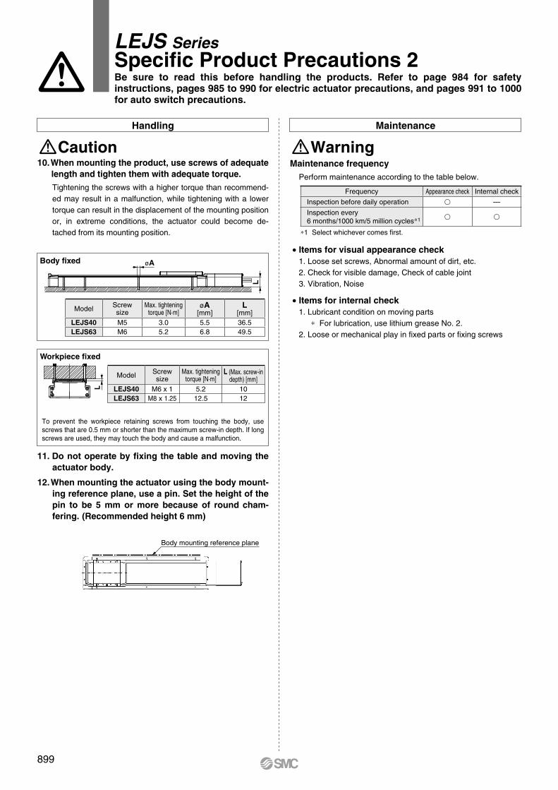
øAL
L
Body mounting reference plane
To prevent the workpiece retaining screws from touching the body, use screws that are 0.5 mm or shorter than the maximum screw-in depth. If long screws are used, they may touch the body and cause a malfunction.
Workpiece fixed
Body fixed
Handling Maintenance
CautionMaintenance frequency
Perform maintenance according to the table below.
∗1 Select whichever comes first.
Warning10. When mounting the product, use screws of adequate
length and tighten them with adequate torque.Tightening the screws with a higher torque than recommend-ed may result in a malfunction, while tightening with a lower torque can result in the displacement of the mounting position or, in extreme conditions, the actuator could become de-tached from its mounting position.
11. Do not operate by fixing the table and moving the actuator body.
12. When mounting the actuator using the body mount-ing reference plane, use a pin. Set the height of the pin to be 5 mm or more because of round cham-fering. (Recommended height 6 mm)
• Items for visual appearance check1. Loose set screws, Abnormal amount of dirt, etc.2. Check for visible damage, Check of cable joint3. Vibration, Noise
• Items for internal check1. Lubricant condition on moving parts
∗ For lubrication, use lithium grease No. 2.2. Loose or mechanical play in fixed parts or fixing screws
LEJS SeriesSpecific Product Precautions 2Be sure to read this before handling the products. Refer to page 984 for safety instructions, pages 985 to 990 for electric actuator precautions, and pages 991 to 1000 for auto switch precautions.
Model Screwsize
Max. tighteningtorque [N·m]
øA[mm]
L[mm]
LEJS40 M5 3.0 5.5 36.5LEJS63 M6 5.2 6.8 49.5
Model Screwsize
Max. tighteningtorque [N·m]
L (Max. screw-indepth) [mm]
LEJS40 M6 x 1 5.2 10LEJS63 M8 x 1.25 12.5 12
Frequency Appearance check Internal check
Inspection before daily operation v —
Inspection every6 months/1000 km/5 million cycles∗1 v v
899
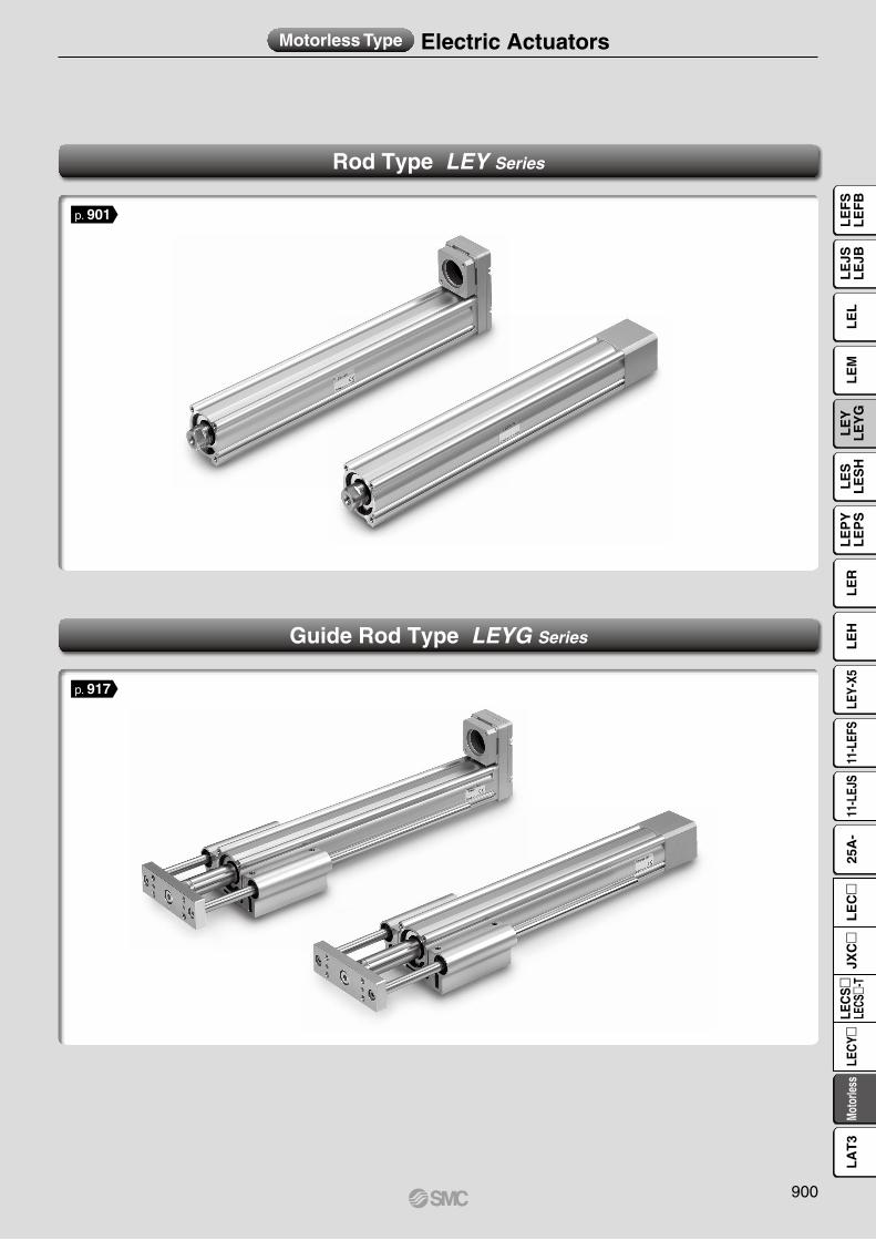
Motorless Type Electric Actuators
Rod Type LEY Series
Guide Rod Type LEYG Series
p. 917
p. 901
900
LE
FS
LE
FB
LE
LL
EJS
LE
JBL
EM
LE
YL
EY
GL
ES
LE
SH
LE
PY
LE
PS
LE
RL
EH
LEY-
X511
-LEF
S11
-LEJ
S25
A-
Moto
rless
LEC
Y�LE
CS
�LE
CS�-
TJX
C�
LE
C�
LA
T3
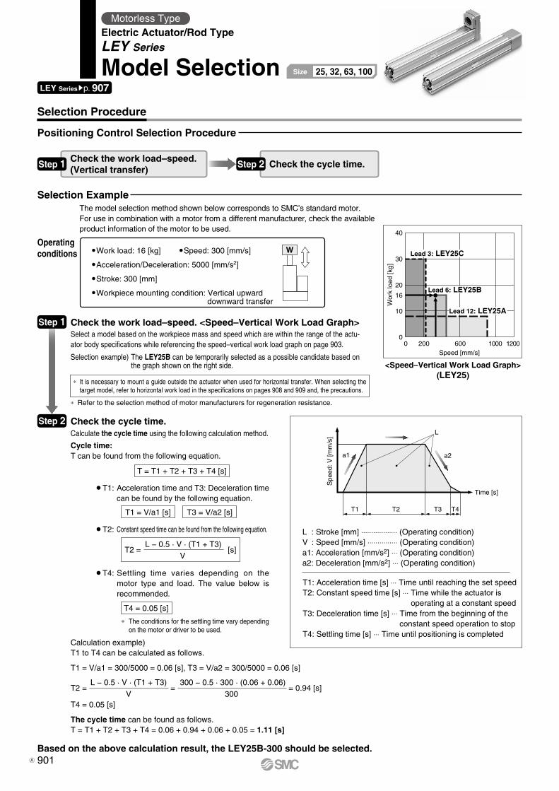
0
10
16
20
30
40
0 200 600 1000 1200Speed [mm/s]
Wor
k lo
ad [k
g]
Lead 12: LEY25A
Lead 6: LEY25B
Lead 3: LEY25C
T1
a1 a2
L
Spe
ed: V
[mm
/s]
Time [s]
T2 T3 T4
W
Check the work load–speed. <Speed–Vertical Work Load Graph>
Check the cycle time.
Work load: 16 [kg] Speed: 300 [mm/s]
Acceleration/Deceleration: 5000 [mm/s2]
Stroke: 300 [mm]
Workpiece mounting condition: Vertical upwarddownward transfer
Calculate the cycle time using the following calculation method.
Cycle time:T can be found from the following equation.
Select a model based on the workpiece mass and speed which are within the range of the actu-ator body specifications while referencing the speed–vertical work load graph on page 903.
Selection example) The LEY25B can be temporarily selected as a possible candidate based on the graph shown on the right side.
T4 = 0.05 [s]
¡T4: Settling time varies depending on the motor type and load. The value below is recommended.
¡T2: Constant speed time can be found from the following equation.
¡T1: Acceleration time and T3: Deceleration time can be found by the following equation.
* It is necessary to mount a guide outside the actuator when used for horizontal transfer. When selecting the target model, refer to horizontal work load in the specifications on pages 908 and 909 and, the precautions.
* Refer to the selection method of motor manufacturers for regeneration resistance.
* The conditions for the settling time vary depending on the motor or driver to be used.
<Speed–Vertical Work Load Graph>(LEY25)
Step 1
Step 2
Operatingconditions
Selection Procedure
Positioning Control Selection Procedure
Selection Example
Step 1 Check the work load–speed.(Vertical transfer) Step 2 Check the cycle time.
T = T1 + T2 + T3 + T4 [s]
T1 = V/a1 [s] T3 = V/a2 [s]
T2 = [s]L − 0.5 · V · (T1 + T3)
V
L : Stroke [mm] ⋅⋅⋅⋅⋅⋅⋅⋅⋅⋅⋅⋅⋅⋅⋅⋅⋅⋅ (Operating condition)V : Speed [mm/s] ⋅⋅⋅⋅⋅⋅⋅⋅⋅⋅⋅⋅⋅⋅⋅ (Operating condition)a1: Acceleration [mm/s2] ⋅⋅⋅ (Operating condition)a2: Deceleration [mm/s2] ⋅⋅⋅ (Operating condition)
T1: Acceleration time [s] ⋅⋅⋅ Time until reaching the set speedT2: Constant speed time [s] ⋅⋅⋅ Time while the actuator is
operating at a constant speedT3: Deceleration time [s] ⋅⋅⋅ Time from the beginning of the
constant speed operation to stopT4: Settling time [s] ⋅⋅⋅ Time until positioning is completed
Calculation example)T1 to T4 can be calculated as follows.
T1 = V/a1 = 300/5000 = 0.06 [s], T3 = V/a2 = 300/5000 = 0.06 [s]
T4 = 0.05 [s]
The cycle time can be found as follows.T = T1 + T2 + T3 + T4 = 0.06 + 0.94 + 0.06 + 0.05 = 1.11 [s]
T2 = = = 0.94 [s]L − 0.5 · V · (T1 + T3)
V
300 − 0.5 · 300 · (0.06 + 0.06)
300
Based on the above calculation result, the LEY25B-300 should be selected.
LEY Seriessp. 907
Motorless TypeElectric Actuator/Rod TypeLEY Series
Model Selection 25, 32, 63, 100Size
The model selection method shown below corresponds to SMC’s standard motor.For use in combination with a motor from a different manufacturer, check the available product information of the motor to be used.
901A
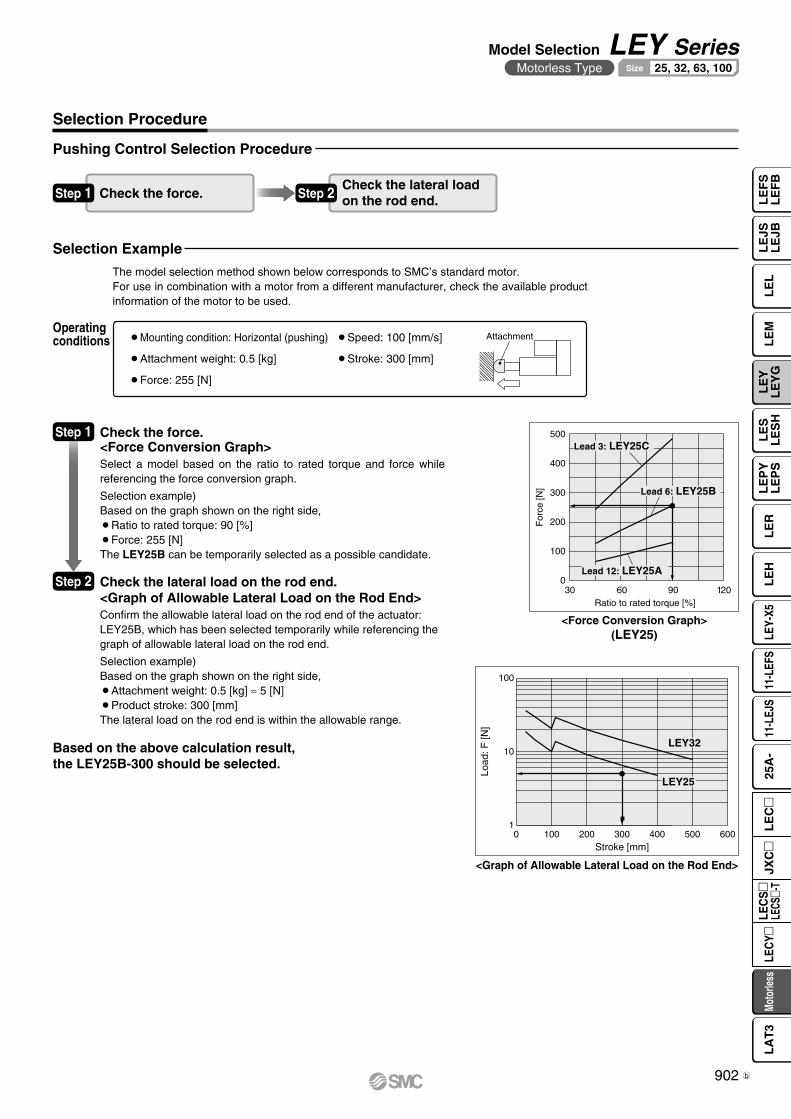
For
ce [N
]
Ratio to rated torque [%]
500
400
300
200
100
06030 12090
Lead 12: LEY25A
Lead 3: LEY25C
Lead 6: LEY25B
Attachment
Load
: F [N
]
Stroke [mm]0 100 200 300 400 500 600
100
10
1
LEY32
LEY25
<Force Conversion Graph>(LEY25)
<Graph of Allowable Lateral Load on the Rod End>
Step 1 Check the force.<Force Conversion Graph>
¡Mounting condition: Horizontal (pushing) ¡Speed: 100 [mm/s]
¡Attachment weight: 0.5 [kg] ¡Stroke: 300 [mm]
¡Force: 255 [N]
Operatingconditions
Pushing Control Selection Procedure
Selection Example
Check the lateral loadon the rod end.Step 1 Check the force.
Select a model based on the ratio to rated torque and force while referencing the force conversion graph.
Selection example)Based on the graph shown on the right side,¡Ratio to rated torque: 90 [%]¡Force: 255 [N]The LEY25B can be temporarily selected as a possible candidate.
Step 2 Check the lateral load on the rod end.<Graph of Allowable Lateral Load on the Rod End>Confirm the allowable lateral load on the rod end of the actuator:LEY25B, which has been selected temporarily while referencing the graph of allowable lateral load on the rod end.
Selection example)Based on the graph shown on the right side,¡Attachment weight: 0.5 [kg] ≈ 5 [N]¡Product stroke: 300 [mm]The lateral load on the rod end is within the allowable range.
Step 2
Based on the above calculation result,the LEY25B-300 should be selected.
Selection Procedure
The model selection method shown below corresponds to SMC’s standard motor.For use in combination with a motor from a different manufacturer, check the available product information of the motor to be used.
902
Model Selection LEY SeriesMotorless Type 25, 32, 63, 100Size
LE
FS
LE
FB
LE
LL
EJS
LE
JBL
EM
LE
YL
EY
GL
ES
LE
SH
LE
PY
LE
PS
LE
RL
EH
LEY-
X511
-LEF
S11
-LEJ
S25
A-
Moto
rless
LEC
Y�LE
CS
�LE
CS�-
TJX
C�
LE
C�
LA
T3
b
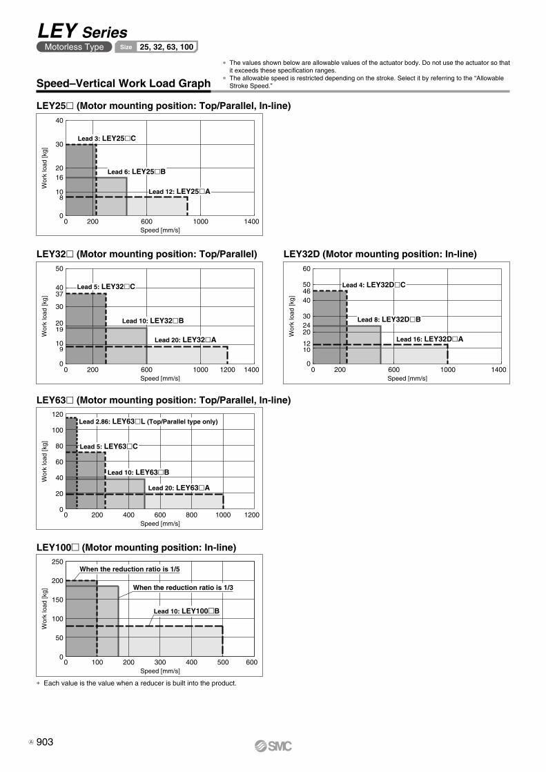
0
10
20
30
40
16
8
0 200 600 1000 1400Speed [mm/s]
Wor
k lo
ad [k
g]
Lead 6: LEY25�B
Lead 3: LEY25�C
Lead 12: LEY25�A
37
19
9
0 200 600 1000 14001200
50
40
30
20
10
0
Speed [mm/s]
Wor
k lo
ad [k
g]
Lead 20: LEY32�A
Lead 5: LEY32�C
Lead 10: LEY32�B
0 200 600 1000 1400
60
50
40
30
20
10
0
12
24
46
Speed [mm/s]
Wor
k lo
ad [k
g]Lead 4: LEY32D�C
Lead 8: LEY32D�B
Lead 16: LEY32D�A
Speed [mm/s]
Wor
k lo
ad [k
g]
0
20
40
60
80
120
100
0 200 400 600 800 1000 1200
Lead 5: LEY63�C
Lead 2.86: LEY63�L (Top/Parallel type only)
Lead 20: LEY63�A
Lead 10: LEY63�B
Speed [mm/s]
Wor
k lo
ad [k
g]
0
50
100
150
250
200
0 100 200 300 400 500 600
Lead 10: LEY100�B
When the reduction ratio is 1/5
When the reduction ratio is 1/3
Speed–Vertical Work Load Graph
* The values shown below are allowable values of the actuator body. Do not use the actuator so that it exceeds these specification ranges.
* The allowable speed is restricted depending on the stroke. Select it by referring to the “Allowable Stroke Speed.”
LEY25l (Motor mounting position: Top/Parallel, In-line)
LEY32l (Motor mounting position: Top/Parallel) LEY32D (Motor mounting position: In-line)
LEY63l (Motor mounting position: Top/Parallel, In-line)
LEY100m (Motor mounting position: In-line)
* Each value is the value when a reducer is built into the product.
903
LEY SeriesMotorless Type 25, 32, 63, 100Size
A
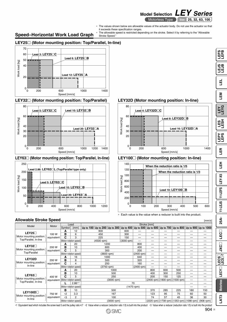
Speed [mm/s]
Wor
k lo
ad [k
g]
0 200 600 1000 14000
20
40
50
60
70
Lead 12: LEY25�A
Lead 3: LEY25�CLead 6: LEY25�B
Wor
k lo
ad [k
g]
Speed [mm/s]0 200 600 1000 14001200
0
20
30
40
60
80
Lead 20: LEY32�A
Lead 5: LEY32�C Lead 10: LEY32�B
Speed [mm/s]
Wor
k lo
ad [k
g]
0 200 600 1000 14000
20
30
40
60
80
Lead 16: LEY32D�A
Lead 4: LEY32D�C
Lead 8: LEY32D�B
Speed [mm/s]
Wor
k lo
ad [k
g]
0
50
100
150
200
250
0 200 400 600 800 12001000
Lead 2.86: LEY63�L (Top/Parallel type only)
Lead 20: LEY63�A
Lead 5: LEY63�C
Lead 10: LEY63�B
Speed [mm/s]
Wor
k lo
ad [k
g]
0
200
400
600
1200
800
1000
1400
0 100 200 300 400 600500
When the reduction ratio is 1/5
When the reduction ratio is 1/3
Lead 10: LEY100�B
* Each value is the value when a reducer is built into the product.
Speed–Horizontal Work Load Graph
* The values shown below are allowable values of the actuator body. Do not use the actuator so that it exceeds these specification ranges.
* The allowable speed is restricted depending on the stroke. Select it by referring to the “Allowable Stroke Speed.”
LEY25l (Motor mounting position: Top/Parallel, In-line)
LEY32l (Motor mounting position: Top/Parallel) LEY32D (Motor mounting position: In-line)
LEY63l (Motor mounting position: Top/Parallel, In-line) LEY100m (Motor mounting position: In-line)
Allowable Stroke Speed
*1 Equivalent lead which includes the screw lead 5 and the pulley ratio 4:7 *2 Value when a reducer (reduction ratio 1/3) is built into the product *3 Value when a reducer (reduction ratio 1/5) is built into the product
[mm/s]
Model MotorLead Stroke [mm]
Symbol [mm] Up to 100 Up to 200 Up to 300 Up to 400 Up to 500 Up to 600 Up to 700 Up to 800 Up to 900 Up to 1000
LEY25mMotor mounting position:
Top/Parallel, In-line
100 Wequivalent
A 12 900 600 — — — — — —B 6 450 300 — — — — — —C 3 225 150 — — — — — —
(Motor rotation speed) (4500 rpm) (3000 rpm) — — — — — —
LEY32mMotor mounting position:
Top/Parallel
200 Wequivalent
A 20 1200 800 — — — — —B 10 600 400 — — — — —C 5 300 200 — — — — —
(Motor rotation speed) (3600 rpm) (2400 rpm) — — — — —
LEY32DMotor mounting position:
In-line
200 Wequivalent
A 16 1000 640 — — — — —B 8 500 320 — — — — —C 4 250 160 — — — — —
(Motor rotation speed) (3750 rpm) (2400 rpm) — — — — —
LEY63mMotor mounting position:
Top/Parallel, In-line
400 Wequivalent
A 20 1000 800 600 500 — —B 10 500 400 300 250 — —C 5 250 200 150 125 — —
(Motor rotation speed) (3000 rpm) (2400 rpm) (1800 rpm) (1500 rpm) — —L 2.86*1 70 — —
(Motor rotation speed) (1470 rpm) — —
LEY100DmMotor mounting position:
In-line
750 Wequivalent
B 10 500 370 285 225 180 150*2 3.3 167 123 95 75 60 50*3 2 100 74 57 45 36 30
(Motor rotation speed) (3000 rpm) (2225 rpm) (1708 rpm) (1353 rpm) (1098 rpm) (908 rpm)
904
Model Selection LEY SeriesMotorless Type 25, 32, 63, 100Size
LE
FS
LE
FB
LE
LL
EJS
LE
JBL
EM
LE
YL
EY
GL
ES
LE
SH
LE
PY
LE
PS
LE
RL
EH
LEY-
X511
-LEF
S11
-LEJ
S25
A-
Moto
rless
LEC
Y�LE
CS
�LE
CS�-
TJX
C�
LE
C�
LA
T3
A
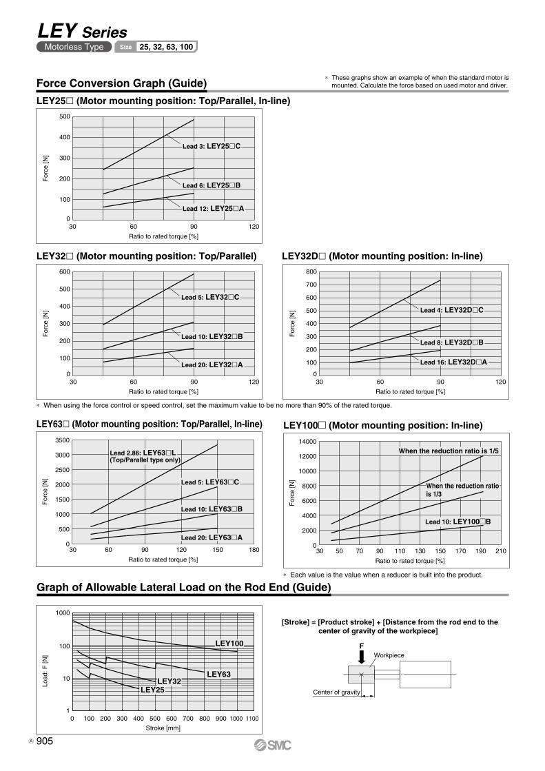
Ratio to rated torque [%]
For
ce [N
]
500
400
300
200
100
06030 12090
Lead 3: LEY25�C
Lead 6: LEY25�B
Lead 12: LEY25�A
Ratio to rated torque [%]
For
ce [N
]
600
500
400
300
200
100
06030 12090
Lead 5: LEY32�C
Lead 10: LEY32�B
Lead 20: LEY32�A
Ratio to rated torque [%]
For
ce [N
]
800
700
600
500
400
300
200
100
06030 12090
Lead 4: LEY32D�C
Lead 8: LEY32D�B
Lead 16: LEY32D�A
Ratio to rated torque [%]
For
ce [N
]
0
500
1000
1500
2000
2500
3000
3500
30 60 90 120 150 180
Lead 2.86: LEY63�L(Top/Parallel type only)
Lead 5: LEY63�C
Lead 10: LEY63�B
Lead 20: LEY63�A
FWorkpiece
Center of gravity
Ratio to rated torque [%]
For
ce [N
]
0
2000
4000
6000
8000
10000
12000
14000
30 7050 11090 130 170150 190 210
Lead 10: LEY100�B
When the reduction ratiois 1/3
When the reduction ratio is 1/5
1
100
10
1000
Stroke [mm]
Load
: F [N
]
0 100 200 300 400 500 600 700 800 900 11001000
LEY63LEY32
LEY25
LEY100
LEY63l (Motor mounting position: Top/Parallel, In-line)
LEY25l (Motor mounting position: Top/Parallel, In-line)
LEY32Dl (Motor mounting position: In-line)LEY32l (Motor mounting position: Top/Parallel)
* When using the force control or speed control, set the maximum value to be no more than 90% of the rated torque.
Graph of Allowable Lateral Load on the Rod End (Guide)
Force Conversion Graph (Guide)
[Stroke] = [Product stroke] + [Distance from the rod end to thecenter of gravity of the workpiece]
* These graphs show an example of when the standard motor is mounted. Calculate the force based on used motor and driver.
LEY100m (Motor mounting position: In-line)
* Each value is the value when a reducer is built into the product.
905
LEY SeriesMotorless Type 25, 32, 63, 100Size
A
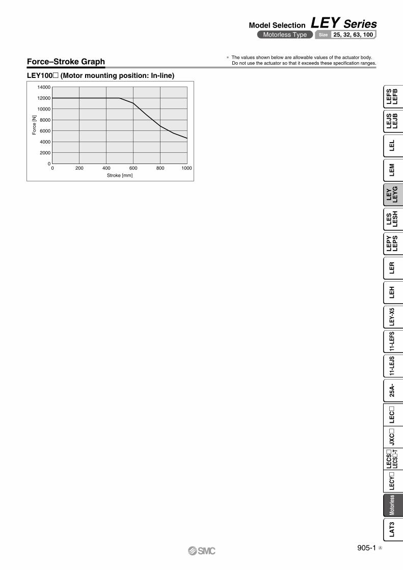
Stroke [mm]
For
ce [N
]
0
2000
4000
6000
8000
10000
12000
14000
0 200 400 600 800 1000
Force–Stroke Graph
LEY100m (Motor mounting position: In-line)
* The values shown below are allowable values of the actuator body.Do not use the actuator so that it exceeds these specification ranges.
905-1
Model Selection LEY SeriesMotorless Type 25, 32, 63, 100Size
LE
FS
LE
FB
LE
LL
EJS
LE
JBL
EM
LE
YL
EY
GL
ES
LE
SH
LE
PY
LE
PS
LE
RL
EH
LEY-
X511
-LEF
S11
-LEJ
S25
A-
Moto
rless
LEC
Y�LE
CS
�LE
CS�-
TJX
C�
LE
C�
LA
T3
A
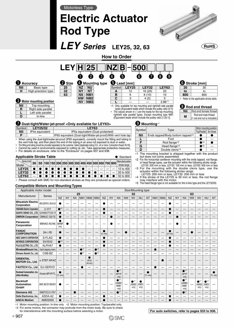
25 500Bw
LEYe r t
Hq y u i o
NZ
∗1 The mounting bracket is shipped together with the product but does not come assembled.
∗2 For the horizontal cantilever mounting with the ends tapped, rod flange, or head flange types, use the actuator within the following stroke range.· LEY25: 200 mm or less, LEY32: 100 mm or less, LEY63: 400 mm or less
∗3 For the mounting with the double clevis type, use the actuator within the following stroke range.· LEY25: 200 mm or less, LEY32: 200 mm or less
∗4 If the stroke of the LEY25 is 30 mm or less, the rod flange may interfere with the motor.
∗5 The head flange type is not available for the in-line type and the LEY32/63.
o Mounting∗1
Symbol TypeMotor mounting positionTop/Parallel In-line
Nil Ends tapped/Body bottom tapped∗2 V VL Foot V —F Rod flange∗2 V∗4 VG Head flange∗2 V∗5 —D Double clevis∗3 V —
i Rod end threadNil Rod end female thread
M Rod end male thread(1 rod end nut is included.)
∗ Refer to the applicable stroke table.
y Stroke [mm]30 30to to
800 800
∗1 Only available for top mounting and right/left side parallel types (Equivalent leads which include the pulley ratio [4:7])
∗ The values shown in ( ) are the leads for the top mounting, right/left side parallel types. Except mounting type NM1 (Equivalent leads which include the pulley ratio [1.25:1])
t Lead [mm]Symbol LEY25 LEY32 LEY63
A 12 16 (20) 20B 6 8 (10) 10C 3 4 (5) 5L — — 2.86∗1
How to Order
q AccuracyNil Basic typeH High-precision type
Applicable Stroke Table V: Standard
∗ Please consult with SMC for non-standard strokes as they are produced as special orders.
Stroke [mm]Model
30 50 100 150 200 250 300 350 400 450 500 600 700 800 Manufacturable stroke range
LEY25 V V V V V V V V V — — — — — 15 to 400LEY32 V V V V V V V V V V V — — — 20 to 500LEY63 — V V V V V V V V V V V V V 50 to 800
e Motor mounting positionNil Top mountingR Right side parallelL Left side parallelD In-line
w Size253263
Motorless Type
Electric ActuatorRod TypeLEY Series LEY25, 32, 63
u Dust-tight/Water-jet-proof <Only available for LEY63>Symbol LEY25/32 LEY63
Nil IP4x equivalent IP5x equivalent (Dust protected)P — IP65 equivalent (Dust-tight/Water-jet-proof)/With vent hole tap
∗ When using the dust-tight/water-jet-proof (lP65 equivalent), correctly mount the fitting and tubing to the vent hole tap, and then place the end of the tubing in an area not exposed to dust or water.
∗ The fitting and tubing should be provided separately by the customer. Select [Applicable tubing O.D.: ø4 or more, Connection thread: Rc1/8].∗ Cannot be used in environments exposed to cutting oil, etc. Take appropriate protective measures.∗ For details on enclosure, refer to the “Enclosure” on pages 937 and 938.
For auto switches, refer to pages 933 to 936.
r Mounting typeNZ NUNY NTNX NM1NW NM2NV NM3
Compatible Motors and Mounting TypesApplicable motor model Size/Mounting type
Manufacturer Series25 32 63
NZ NY NX NM1 NM2 NM3 NZ NY NX NW NV NU NT NM1 NM2 NZ NY NX NW NV NU NT
Mitsubishi ElectricCorporation MELSERVO JN/J4/J5 V — — — — — V — — — — — — — — V — — — — — —
YASKAWA Electric Corporation Σ-V/7 V∗3 — — — — — V — — — — — — — — V — — — — — —SANYO DENKI CO., LTD. SANMOTION R V — — — — — V — — — — — — — — V — — — — — —OMRON Corporation OMNUC G5/1S V — — — — — — V — — — — — — — — V — — — — —
PanasonicCorporation MINAS A5/A6
V(MHMF
only)V — — — — — V — — — — — — — — V — — — — —
FANUCCORPORATION βis (-B) V — — — — — V
(β1 only) — — V — — — — — V(β1 only) — — V — — —
NIDEC SANKYO CORPORATION S-FLAG V — — — — — V — — — — — — — — V — — — — — —KEYENCE CORPORATION SV/SV2 V∗3 — — — — — V — — — — — — — — V — — — — — —FUJI ELECTRIC CO., LTD. ALPHA7 V — — — — — V — — — — — — — — V — — — — — —MinebeaMitsumi Inc. Hybrid stepping motors — — — V∗1 — V∗2 — — — — — — — V — — — — — — — —Shinano Kenshi Co., Ltd. CSB-BZ — — — V∗1 — V∗2 — — — — — — — — — — — — — — — —
ORIENTAL MOTOR Co., Ltd. α STEP AR/AZ — — — —
VAR/AZ
(46 only)— — — — — — — — — V — — — — — — —
FASTECH Co., Ltd. Ezi-SERVO — — — V — — — — — — — — — V — — — — — — — —
Rockwell Automation, Inc.(Allen-Bradley) Kinetix MP/VP/TL V
(TL only)— — — — — — —
V∗1
(MP/VP only)
— — — V(TL only)
— — — —V∗1
(MPVP only)
— — — V(TL only)
BeckhoffAutomation GmbH
AM 30/31/80/81 V — — — — — — —
V∗1
(AM80/AM81 only)
—V∗1
(AM30 only)
V(AM31 only)
— — — — —
V∗1
(AM80/AM81 only)
—V∗1
(AM30 only)
V∗1
(AM31 only)
—
Siemens AG SIMOTICS S-1FK7 — — V — — — — — V∗1 — — — — — — — — V∗1 — — — —Delta Electronics, Inc. ASDA-A2 V — — — — — V — — — — — — — — V — — — — — —ANCA Motion AMD2000 V — — — — — V — — — — — — — — V — — — — — —
∗1 Motor mounting position: In-line only ∗2 Motor mounting position: Top/parallel only∗3 For some motors, the connector may protrude from the motor body. Be sure to check
for interreference with the mounting surface before selecting a motor.
907B
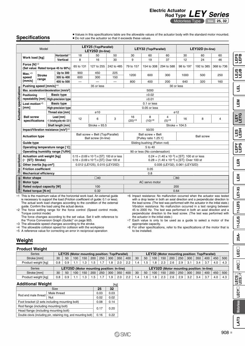
Specifications¡Values in this specifications table are the allowable values of the actuator body with the standard motor mounted.¡Do not use the actuator so that it exceeds these values.
∗1 This is the maximum value of the horizontal work load. An external guide is necessary to support the load (Friction coefficient of guide: 0.1 or less). The actual work load changes according to the condition of the external guide. Confirm the load using the actual device.
∗2 The force setting range for the force control (Speed control mode, Torque control mode)The force changes according to the set value. Set it with reference to the “Force Conversion Graph (Guide)” on page 905.
∗3 The allowable speed changes according to the stroke.∗4 The allowable collision speed for collision with the workpiece∗5 A reference value for correcting an error in reciprocal operation
∗6 Impact resistance: No malfunction occurred when the actuator was tested with a drop tester in both an axial direction and a perpendicular direction to the lead screw. (The test was performed with the actuator in the initial state.)Vibration resistance: No malfunction occurred in a test ranging between 45 to 2000 Hz. The test was performed in both an axial direction and a perpendicular direction to the lead screw. (The test was performed with the actuator in the initial state.)
∗7 Each value is only to be used as a guide to select a motor of the appropriate capacity.
∗8 For other specifications, refer to the specifications of the motor that is to be installed.
ModelLEY25 (Top/Parallel)
LEY25D (In-line)LEY32 (Top/Parallel) LEY32D (In-line)
Act
uat
or
spec
ifica
tio
ns
Work load [kg]Horizontal∗1 18 50 50 30 60 60 30 60 60
Vertical 8 16 30 9 19 37 12 24 46
Force [N]∗2
(Set value: Rated torque 45 to 90%)65 to 131 127 to 255 242 to 485 79 to 157 154 to 308 294 to 588 98 to 197 192 to 385 368 to 736
Max.∗3
speed[mm/s]
Strokerange
Up to 300 900 450 2251200 600 300 1000 500 250
305 to 400 600 300 150405 to 500 — — — 800 400 200 640 320 160
Pushing speed [mm/s]∗4 35 or less 30 or lessMax. acceleration/deceleration [mm/s2] 5000
Positioning repeatability [mm]
Basic type ±0.02High-precision type ±0.01
Lost motion∗5
[mm]Basic type 0.1 or less
High-precision type 0.05 or less
Ball screw specifications
Thread size [mm] ø10 ø12
Lead [mm]∗9 (including pulley ratio 1.25:1)
12 6 316
(20)∗98
(10)∗94
(5)∗9 16 8 4
Shaft length [mm] Stroke + 93.5 Stroke + 104.5Impact/Vibration resistance [m/s2]∗6 50/20
Actuation typeBall screw + Belt (Top/Parallel)
Ball screw (In-line)Ball screw + Belt
[Pulley ratio 1.25:1]Ball screw
Guide type Sliding bushing (Piston rod)Operating temperature range [°C] 5 to 40Operating humidity range [%RH] 90 or less (No condensation)
Othe
r spe
cifica
tions Actuation unit weight [kg]
(∗ [ST]: Stroke)0.15 + (0.69 x 10⁻³) x [ST]: 100 st or less0.16 + (0.69 x 10⁻³) x [ST]: Over 100 st
0.24 + (1.40 x 10⁻³) x [ST]: 100 st or less0.28 + (1.40 x 10⁻³) x [ST]: Over 100 st
Other inertia [kg·cm2] 0.012 (LEY25), 0.015 (LEY25D) 0.035 (LEY32), 0.061 (LEY32D)Friction coefficient 0.05Mechanical efficiency 0.8
Refere
nce mo
tor spe
c. Motor shape 40 60Motor type AC servo motorRated output capacity [W] 100 200Rated torque [N·m] 0.32 0.64
∗7
∗8
Weight
Product Weight
Series LEY25D (Motor mounting position: In-line) LEY32D (Motor mounting position: In-line)Stroke [mm] 30 50 100 150 200 250 300 350 400 30 50 100 150 200 250 300 350 400 450 500
Product weight [kg] 0.8 0.9 1.1 1.3 1.5 1.7 1.9 2.0 2.2 1.4 1.6 1.8 2.3 2.6 2.9 3.2 3.4 3.7 4.0 4.3
Series LEY25 (Motor mounting position: Top/Parallel) LEY32 (Motor mounting position: Top/Parallel)Stroke [mm] 30 50 100 150 200 250 300 350 400 30 50 100 150 200 250 300 350 400 450 500
Product weight [kg] 0.8 0.9 1.1 1.3 1.5 1.7 1.8 2.0 2.2 1.4 1.5 1.8 2.3 2.6 2.9 3.1 3.4 3.7 4.0 4.3
[kg]Additional WeightSize 25 32
Rod end male threadMale thread 0.03 0.03Nut 0.02 0.02
Foot bracket (2 sets including mounting bolt) 0.08 0.14Rod flange (including mounting bolt)
0.17 0.20Head flange (including mounting bolt)Double clevis (including pin, retaining ring, and mounting bolt) 0.16 0.22
908
Electric ActuatorRod Type LEY Series
Motorless Type 25, 32Size
LE
FS
LE
FB
LE
LL
EJS
LE
JBL
EM
LE
YL
EY
GL
ES
LE
SH
LE
PY
LE
PS
LE
RL
EH
LEY-
X511
-LEF
S11
-LEJ
S25
A-
Moto
rless
LEC
Y�LE
CS
�LE
CS�-
TJX
C�
LE
C�
LA
T3
B
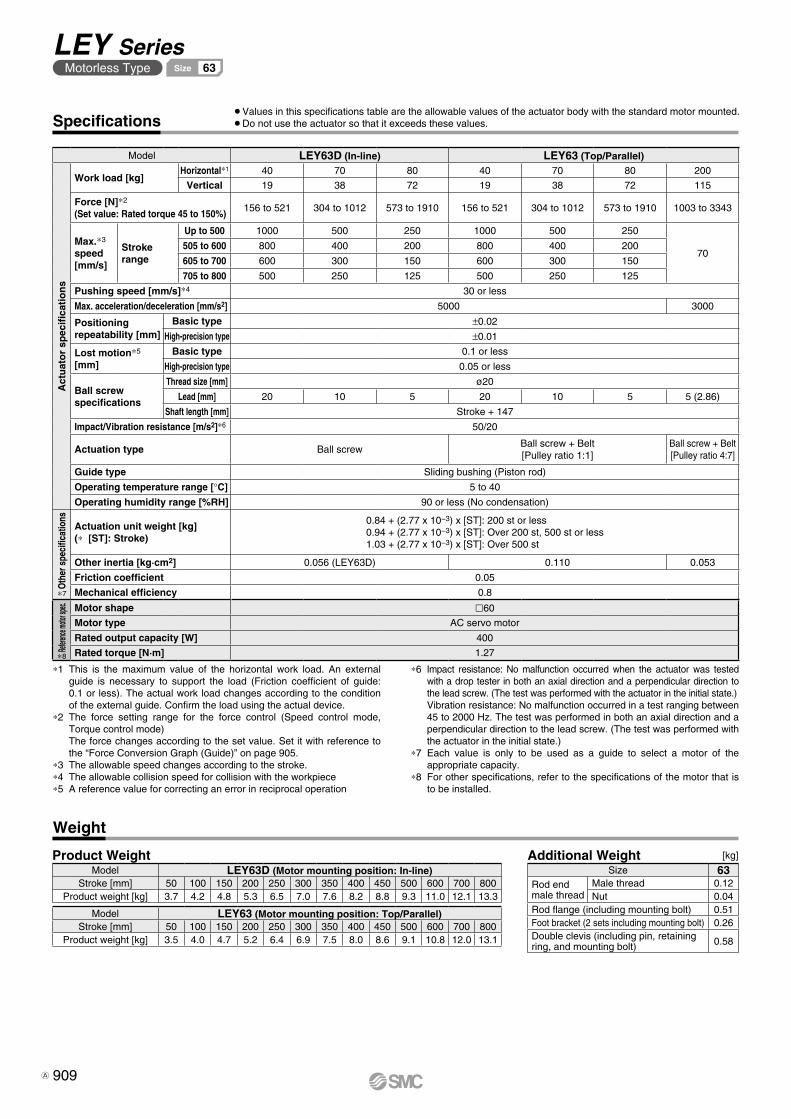
Model LEY63D (In-line) LEY63 (Top/Parallel)
Act
uat
or
spec
ifica
tio
ns
Work load [kg]Horizontal∗1 40 70 80 40 70 80 200
Vertical 19 38 72 19 38 72 115
Force [N]∗2
(Set value: Rated torque 45 to 150%)156 to 521 304 to 1012 573 to 1910 156 to 521 304 to 1012 573 to 1910 1003 to 3343
Max.∗3
speed[mm/s]
Strokerange
Up to 500 1000 500 250 1000 500 250
70505 to 600 800 400 200 800 400 200
605 to 700 600 300 150 600 300 150
705 to 800 500 250 125 500 250 125
Pushing speed [mm/s]∗4 30 or less
Max. acceleration/deceleration [mm/s2] 5000 3000
Positioning repeatability [mm]
Basic type ±0.02
High-precision type ±0.01
Lost motion∗5
[mm]Basic type 0.1 or less
High-precision type 0.05 or less
Ball screw specifications
Thread size [mm] ø20
Lead [mm] 20 10 5 20 10 5 5 (2.86)
Shaft length [mm] Stroke + 147
Impact/Vibration resistance [m/s2]∗6 50/20
Actuation type Ball screwBall screw + Belt[Pulley ratio 1:1]
Ball screw + Belt[Pulley ratio 4:7]
Guide type Sliding bushing (Piston rod)
Operating temperature range [°C] 5 to 40
Operating humidity range [%RH] 90 or less (No condensation)
Oth
er s
peci
ficat
ions
Actuation unit weight [kg](∗ [ST]: Stroke)
0.84 + (2.77 x 10⁻³) x [ST]: 200 st or less0.94 + (2.77 x 10⁻³) x [ST]: Over 200 st, 500 st or less1.03 + (2.77 x 10⁻³) x [ST]: Over 500 st
Other inertia [kg·cm2] 0.056 (LEY63D) 0.110 0.053
Friction coefficient 0.05
Mechanical efficiency 0.8
Refere
nce mo
tor sp
ec. Motor shape l60
Motor type AC servo motor
Rated output capacity [W] 400
Rated torque [N·m] 1.27
∗7
Specifications
Weight
¡Values in this specifications table are the allowable values of the actuator body with the standard motor mounted.¡Do not use the actuator so that it exceeds these values.
∗1 This is the maximum value of the horizontal work load. An external guide is necessary to support the load (Friction coefficient of guide: 0.1 or less). The actual work load changes according to the condition of the external guide. Confirm the load using the actual device.
∗2 The force setting range for the force control (Speed control mode, Torque control mode)The force changes according to the set value. Set it with reference to the “Force Conversion Graph (Guide)” on page 905.
∗3 The allowable speed changes according to the stroke.∗4 The allowable collision speed for collision with the workpiece∗5 A reference value for correcting an error in reciprocal operation
∗6 Impact resistance: No malfunction occurred when the actuator was tested with a drop tester in both an axial direction and a perpendicular direction to the lead screw. (The test was performed with the actuator in the initial state.)Vibration resistance: No malfunction occurred in a test ranging between 45 to 2000 Hz. The test was performed in both an axial direction and a perpendicular direction to the lead screw. (The test was performed with the actuator in the initial state.)
∗7 Each value is only to be used as a guide to select a motor of the appropriate capacity.
∗8 For other specifications, refer to the specifications of the motor that is to be installed.
Model LEY63D (Motor mounting position: In-line)Stroke [mm] 50 100 150 200 250 300 350 400 450 500 600 700 800
Product weight [kg] 3.7 4.2 4.8 5.3 6.5 7.0 7.6 8.2 8.8 9.3 11.0 12.1 13.3
Model LEY63 (Motor mounting position: Top/Parallel)Stroke [mm] 50 100 150 200 250 300 350 400 450 500 600 700 800
Product weight [kg] 3.5 4.0 4.7 5.2 6.4 6.9 7.5 8.0 8.6 9.1 10.8 12.0 13.1
Additional Weight [kg]
Size 63Rod end male thread
Male thread 0.12Nut 0.04
Rod flange (including mounting bolt) 0.51Foot bracket (2 sets including mounting bolt) 0.26Double clevis (including pin, retaining ring, and mounting bolt) 0.58
Product Weight
∗8
909
LEY SeriesMotorless Type 63Size
A

909-1 A
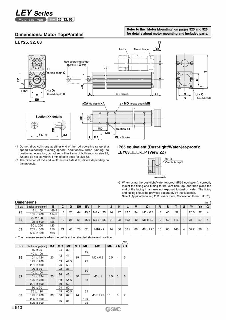
TU
M
SM 4 x O1
thread depth R
Y2
Y1B + StrokeL
øD
Rod operating range∗1
(Stroke + G mm)
Hthread depth C
4 x O1
thread depth R
EV
J
�K∗2
MEH
Motor flangeMotor
ZZ
øXA H9 depth XA 6 x MO thread depth MR
MH
L MA
MDMC
ML + Stroke
Section XX
XA H9
XB
XA
Rc1/8Vent hole tap∗3
18
Dimensions: Motor Top/Parallel
LEY25, 32, 63
∗1 Do not allow collisions at either end of the rod operating range at a speed exceeding “pushing speed.” Additionally, when running the positioning operation, do not set within 2 mm of both ends for size 25, 32, and do not set within 4 mm of both ends for size 63.
∗2 The direction of rod end width across flats (lK) differs depending on the products.
Dimensions [mm]
∗ The L measurement is when the unit is at the retracted stroke end position.
Size Stroke range [mm] B C D EH EV H J K L M O1 R S T U Y1 Y2 G
2515 to 100 89.5
13 20 44 45.5 M8 x 1.25 24 17 12.5 34 M5 x 0.8 8 46 92 1 26.5 22 4105 to 400 114.5
3220 to 100 96
13 25 51 56.5 M8 x 1.25 31 22 16.5 40 M6 x 1.0 10 60 118 1 34 27 4105 to 500 126
6350 to 200 123
21 40 76 82 M16 x 2 44 36 33.4 60 M8 x 1.25 16 80 146 4 32.2 29 8205 to 500 158505 to 800 193
Section XX details
[mm]
Size Stroke range [mm] MA MC MD MH ML MO MR XA XB
25
15 to 39
20
24 32
29
50
M5 x 0.8 6.5 4 540 to 100
42 41101 to 124
75125 to 200 59 49.5201 to 400 76 58
32
20 to 39
25
22 36
30
50
M6 x 1 8.5 5 640 to 100
36 43101 to 124
80125 to 200 53 51.5201 to 500 70 60
63
50 to 70
38
24 50
44 65
M8 x 1.25 10 6 775 to 120 45 60.5
125 to 200 58 67205 to 500
86 81100
505 to 800 135
IP65 equivalent (Dust-tight/Water-jet-proof): LEY63lll-lP (View ZZ)
∗3 When using the dust-tight/water-jet-proof (lP65 equivalent), correctly mount the fitting and tubing to the vent hole tap, and then place the end of the tubing in an area not exposed to dust or water. The fitting and tubing should be provided separately by the customer.Select [Applicable tubing O.D.: ø4 or more, Connection thread: Rc1/8].
Refer to the “Motor Mounting” on pages 925 and 926 for details about motor mounting and included parts.
910
LEY SeriesMotorless Type 25, 32, 63Size
A
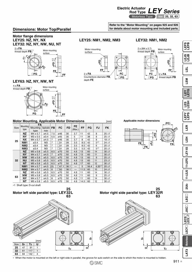
2 x FACounterbore diameter FB, depth FE
�FGFC
FF
øF
D
Motor mounting surface
�FGFC 2 x FA
thread depth FB
FF
øF
D
2 x (M4 x 0.7)thread depth FB
Motor mounting surface
FFFE
Motor mounting surface
FC øF
D +
0.3
+0.
145°
�FG
2 x FAthread depth FB
S1
T2 U T2
S1
U
4 x FAthread depth FB
Motor mounting surface
FG FFFE
FC øF
D +
0.3
+0.
1
FC
øF
D
FK
øF
JFE FA
(FC)
LEY25: NZ, NY, NXLEY32: NZ, NY, NW, NU, NT
Motor flange dimensions
LEY63: NZ, NY, NW, NT
LEY32: NM1, NM2
Applicable motor dimensions
LEY25: NM1, NM2, NM3
[mm]
∗ When the motor is mounted on the left or right side in parallel, the groove for auto switch on the side to which the motor is mounted is hidden.
Motor left side parallel type: LEY L253263
Motor right side parallel type: LEY R253263
Size S1 T2 U25 47 91 132 61 117 163 84 142 4
Dimensions: Motor Top/ParallelRefer to the “Motor Mounting” on pages 925 and 926 for details about motor mounting and included parts.
Motor Mounting, Applicable Motor Dimensions [mm]
SizeMounting
type
FAFB FC FD FE
(Max.)FF FG FJ FKMounting
typeApplicable
motor
25
NZ M4 x 0.7 ø4.5 7.5 ø46 30 3.7 11 42 8 25 ±1NY M3 x 0.5 ø3.4 5.5 ø45 30 5 11 38 8 25 ±1NX M4 x 0.7 ø4.5 7 ø46 30 3.7 8 42 8 18 ±1
NM1 ø3.4 M3 7 m31 28 3.5 8.5 42 5∗1 24 ±1NM2 ø3.4 M3 7 m31 28 3.5 8.5 42 6 20 ±1NM3 ø3.4 M3 7 m31 28 3.5 5.5 42 5∗1 20 ±1
32
NZ M5 x 0.8 ø5.5 8.5 ø70 50 4.6 13 60 14 30 ±1NY M4 x 0.7 ø4.5 7 ø70 50 4.6 13 60 11 30 ±1NW M5 x 0.8 ø5.5 8.5 ø70 50 4.6 13 60 9 25 ±1NU M5 x 0.8 ø5.5 8.5 ø70 50 4.6 13 60 11 23 ±1NT M5 x 0.8 ø5.5 8.5 ø70 50 4.6 17 60 12 30 ±1
NM1 M4 x 0.7 ø4.5 (5) m47.1 38.1 — 5 56.4 6.35∗1 20 ±1NM2 M4 x 0.7 ø4.5 8 m50 38.1 — 11.5 60 10 24 ±1
63
NZ M5 x 0.8 ø5.5 8.5 ø70 50 4.6 11 60 14 30 ±1NW M5 x 0.8 ø5.5 8.5 ø70 50 4.6 11 60 9 25 ±1NY M4 x 0.7 ø4.5 8 ø70 50 4.6 11 60 14 30 ±1NT M5 x 0.8 ø5.5 8.5 ø70 50 4.6 14.5 60 12 30 ±1
∗1 Shaft type: D-cut shaft
911
Electric ActuatorRod Type LEY Series
Motorless Type 25, 32, 63Size
LE
FS
LE
FB
LE
LL
EJS
LE
JBL
EM
LE
YL
EY
GL
ES
LE
SH
LE
PY
LE
PS
LE
RL
EH
LEY-
X511
-LEF
S11
-LEJ
S25
A-
Moto
rless
LEC
Y�LE
CS
�LE
CS�-
TJX
C�
LE
C�
LA
T3
A
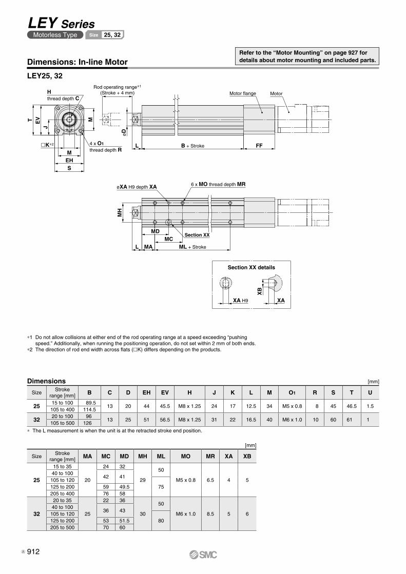
MotorMotor flange
FFB + StrokeL
Rod operating range∗1
(Stroke + 4 mm)Hthread depth C
M
SEHM
�K∗2 4 x O1
thread depth R
T EV
J
øD
6 x MO thread depth MRøXA H9 depth XA
MH
L MA
MDMC
ML + Stroke
Section XX
XA H9
XB
XA
LEY25, 32
Dimensions [mm]
* The L measurement is when the unit is at the retracted stroke end position.
SizeStroke
range [mm] B C D EH EV H J K L M O1 R S T U
2515 to 100 89.5
13 20 44 45.5 M8 x 1.25 24 17 12.5 34 M5 x 0.8 8 45 46.5 1.5105 to 400 114.5
3220 to 100 96
13 25 51 56.5 M8 x 1.25 31 22 16.5 40 M6 x 1.0 10 60 61 1105 to 500 126
Section XX details
[mm]
SizeStroke
range [mm] MA MC MD MH ML MO MR XA XB
25
15 to 35
20
24 32
29
50
M5 x 0.8 6.5 4 540 to 100
42 41105 to 120
75125 to 200 59 49.5205 to 400 76 58
32
20 to 35
25
22 36
30
50
M6 x 1.0 8.5 5 640 to 100
36 43105 to 120
80125 to 200 53 51.5205 to 500 70 60
Dimensions: In-line Motor
*1 Do not allow collisions at either end of the rod operating range at a speed exceeding “pushing speed.” Additionally, when running the positioning operation, do not set within 2 mm of both ends.
*2 The direction of rod end width across flats (lK) differs depending on the products.
Refer to the “Motor Mounting” on page 927 for details about motor mounting and included parts.
912
LEY SeriesMotorless Type 25, 32Size
A
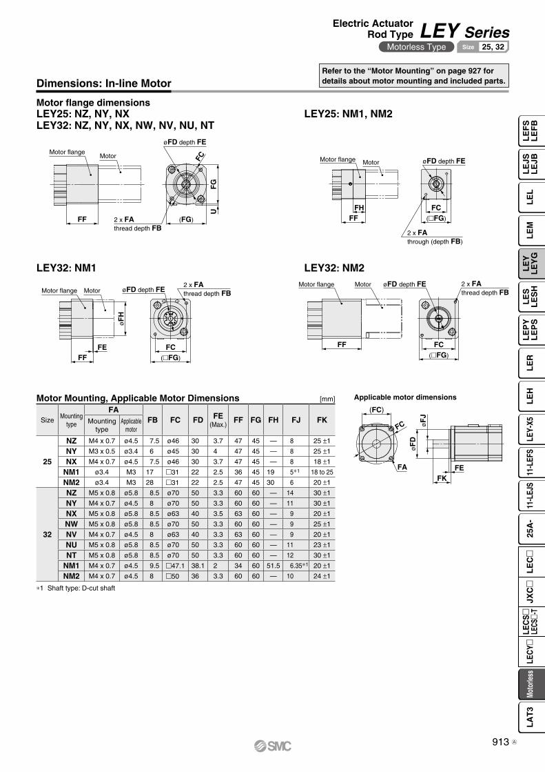
FFFH
Motor flange Motor
2 x FAthrough (depth FB)
(�FG)
FC
øFD depth FE
Motor flange Motor
FEFF (�FG)
FC
øF
H
2 x FAthread depth FBøFD depth FE
Motor flange Motor
FF
øFD depth FE 2 x FAthread depth FB
(�FG)
FC
FA
FC øF
J
FKFE
øF
D(FC)
Motor flangeMotor
øFD depth FE
(FG)
FC
2 x FAthread depth FB
UF
GFF
Dimensions: In-line Motor
LEY32: NM1
LEY25: NZ, NY, NXLEY32: NZ, NY, NX, NW, NV, NU, NT
LEY25: NM1, NM2
LEY32: NM2
Motor flange dimensions
Applicable motor dimensionsMotor Mounting, Applicable Motor Dimensions [mm]
SizeMounting
type
FAFB FC FD FE
(Max.)FF FG FH FJ FKMounting
typeApplicable
motor
25
NZ M4 x 0.7 ø4.5 7.5 ø46 30 3.7 47 45 — 8 25 ±1
NY M3 x 0.5 ø3.4 6 ø45 30 4 47 45 — 8 25 ±1
NX M4 x 0.7 ø4.5 7.5 ø46 30 3.7 47 45 — 8 18 ±1
NM1 ø3.4 M3 17 m31 22 2.5 36 45 19 5∗1 18 to 25
NM2 ø3.4 M3 28 m31 22 2.5 47 45 30 6 20 ±1
32
NZ M5 x 0.8 ø5.8 8.5 ø70 50 3.3 60 60 — 14 30 ±1
NY M4 x 0.7 ø4.5 8 ø70 50 3.3 60 60 — 11 30 ±1
NX M5 x 0.8 ø5.8 8.5 ø63 40 3.5 63 60 — 9 20 ±1
NW M5 x 0.8 ø5.8 8.5 ø70 50 3.3 60 60 — 9 25 ±1
NV M4 x 0.7 ø4.5 8 ø63 40 3.3 63 60 — 9 20 ±1
NU M5 x 0.8 ø5.8 8.5 ø70 50 3.3 60 60 — 11 23 ±1
NT M5 x 0.8 ø5.8 8.5 ø70 50 3.3 60 60 — 12 30 ±1
NM1 M4 x 0.7 ø4.5 9.5 m47.1 38.1 2 34 60 51.5 6.35∗1 20 ±1
NM2 M4 x 0.7 ø4.5 8 m50 36 3.3 60 60 — 10 24 ±1
∗1 Shaft type: D-cut shaft
Refer to the “Motor Mounting” on page 927 for details about motor mounting and included parts.
913
Electric ActuatorRod Type LEY Series
Motorless Type 25, 32Size
LE
FS
LE
FB
LE
LL
EJS
LE
JBL
EM
LE
YL
EY
GL
ES
LE
SH
LE
PY
LE
PS
LE
RL
EH
LEY-
X511
-LEF
S11
-LEJ
S25
A-
Moto
rless
LEC
Y�LE
CS
�LE
CS�-
TJX
C�
LE
C�
LA
T3
A

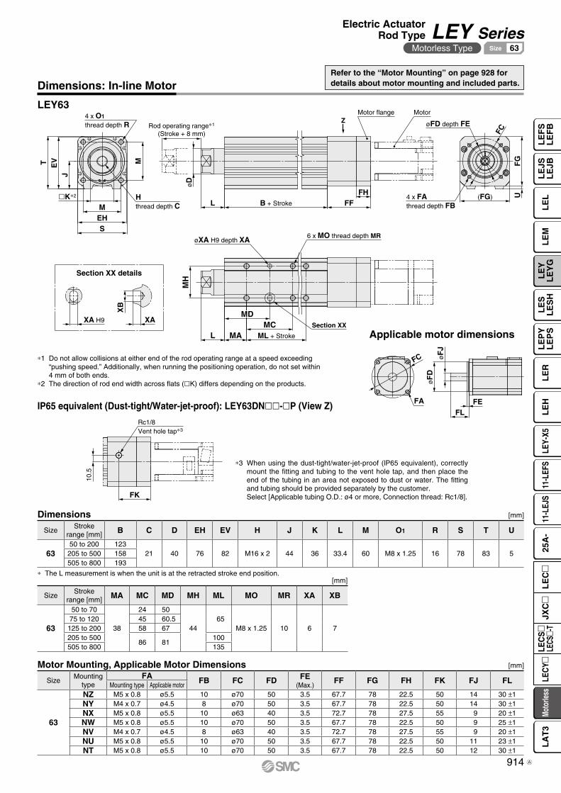
FK
10.5
Rc1/8Vent hole tap∗3
FC
FHFF
(FG)B + StrokeL
øD
Rod operating range∗1
(Stroke + 8 mm)M
SEHM
T EV
J
UF
G
Z
4 x FAthread depth FB
øFD depth FE
Motor flange Motor
Hthread depth C
4 x O1
thread depth R
�K∗2
6 x MO thread depth MR
Section XX
øXA H9 depth XA
MH
L MA
MDMC
ML + Stroke
XA H9
XB
XA
FC øF
J
FLFE
øF
D
FA
LEY63
Applicable motor dimensions
Section XX details
[mm]
SizeStroke
range [mm] MA MC MD MH ML MO MR XA XB
63
50 to 70
38
24 50
44 65
M8 x 1.25 10 6 775 to 120 45 60.5125 to 200 58 67205 to 500
86 81100
505 to 800 135
Dimensions: In-line Motor
∗3 When using the dust-tight/water-jet-proof (lP65 equivalent), correctly mount the fitting and tubing to the vent hole tap, and then place the end of the tubing in an area not exposed to dust or water. The fitting and tubing should be provided separately by the customer.Select [Applicable tubing O.D.: ø4 or more, Connection thread: Rc1/8].
IP65 equivalent (Dust-tight/Water-jet-proof): LEY63DNll-lP (View Z)
∗ The L measurement is when the unit is at the retracted stroke end position.
∗1 Do not allow collisions at either end of the rod operating range at a speed exceeding “pushing speed.” Additionally, when running the positioning operation, do not set within 4 mm of both ends.
∗2 The direction of rod end width across flats (lK) differs depending on the products.
Dimensions [mm]
SizeStroke
range [mm] B C D EH EV H J K L M O1 R S T U
6350 to 200 123
21 40 76 82 M16 x 2 44 36 33.4 60 M8 x 1.25 16 78 83 5205 to 500 158505 to 800 193
Refer to the “Motor Mounting” on page 928 for details about motor mounting and included parts.
Motor Mounting, Applicable Motor Dimensions [mm]
SizeMounting
typeFA FB FC FD FE
(Max.)FF FG FH FK FJ FL
Mounting type Applicable motor
63
NZ M5 x 0.8 ø5.5 10 ø70 50 3.5 67.7 78 22.5 50 14 30 ±1NY M4 x 0.7 ø4.5 8 ø70 50 3.5 67.7 78 22.5 50 14 30 ±1NX M5 x 0.8 ø5.5 10 ø63 40 3.5 72.7 78 27.5 55 9 20 ±1NW M5 x 0.8 ø5.5 10 ø70 50 3.5 67.7 78 22.5 50 9 25 ±1NV M4 x 0.7 ø4.5 8 ø63 40 3.5 72.7 78 27.5 55 9 20 ±1NU M5 x 0.8 ø5.5 10 ø70 50 3.5 67.7 78 22.5 50 11 23 ±1NT M5 x 0.8 ø5.5 10 ø70 50 3.5 67.7 78 22.5 50 12 30 ±1
914
Electric ActuatorRod Type LEY Series
Motorless Type 63Size
LE
FS
LE
FB
LE
LL
EJS
LE
JBL
EM
LE
YL
EY
GL
ES
LE
SH
LE
PY
LE
PS
LE
RL
EH
LEY-
X511
-LEF
S11
-LEJ
S25
A-
Moto
rless
LEC
Y�LE
CS
�LE
CS�-
TJX
C�
LE
C�
LA
T3
A
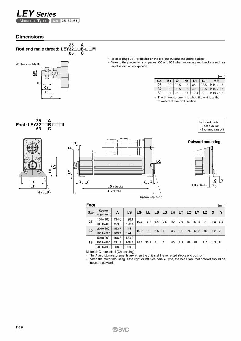
LY
LH
LXLZ
LTLL
LT
YX
A + Stroke
LS + Stroke
XY
LG
YXLS1
4 x øLDSpecial cap bolt
LS + Stroke
MM
L1
L2
C1
H1
Width across flats B1
[mm]Foot
Material: Carbon steel (Chromating)* The A and LL measurements are when the unit is at the retracted stroke end position.* When the motor mounting is the right or left side parallel type, the head side foot bracket should be
mounted outward.
Outward mounting
SizeStroke
range [mm] A LS LS1 LL LD LG LH LT LX LY LZ X Y
2515 to 100 134.6 98.8
19.8 6.4 6.6 3.5 30 2.6 57 51.5 71 11.2 5.8105 to 400 159.6 123.8
3220 to 100 153.7 114
19.2 9.3 6.6 4 36 3.2 76 61.5 90 11.2 7105 to 500 183.7 144
6350 to 200 196.8 133.2
25.2 25.2 9 5 50 3.2 95 88 110 14.2 8205 to 500 231.8 168.2
505 to 800 266.8 203.2
Dimensions
Included parts · Foot bracket · Body mounting bolt
* Refer to page 361 for details on the rod end nut and mounting bracket.* Refer to the precautions on pages 938 and 939 when mounting end brackets such as
knuckle joint or workpieces.
[mm]
* The L1 measurement is when the unit is at the retracted stroke end position.
Size B1 C1 H1 L1 L2 MM25 22 20.5 8 36 23.5 M14 x 1.532 22 20.5 8 40 23.5 M14 x 1.563 27 26 11 72.4 39 M18 x 1.5
Foot: LEY ll -lllL253263
ABC
Rod end male thread: LEY ll -llM253263
ABC
915
LEY SeriesMotorless Type 25, 32, 63Size
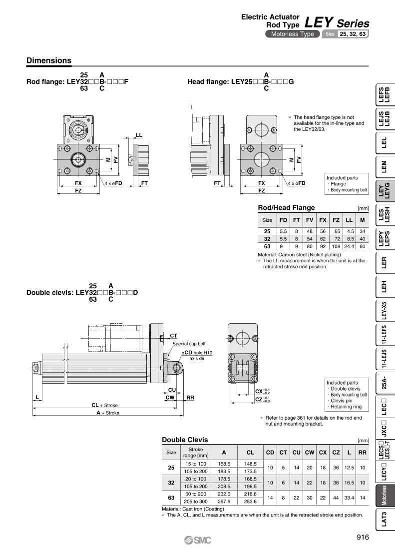
CX
CZ
CURRCWL
CL + Stroke
A + Stroke
CT
+0.4+0.2
−0.1−0.3
Special cap bolt
øCD hole H10axis d9
FZFX
FVM
FT
LL
FTFZFX
M FV
4 x øFD 4 x øFD
[mm]Double Clevis
Material: Cast iron (Coating)* The A, CL, and L measurements are when the unit is at the retracted stroke end position.
SizeStroke
range [mm] A CL CD CT CU CW CX CZ L RR
2515 to 100 158.5 148.5
10 5 14 20 18 36 12.5 10105 to 200 183.5 173.5
3220 to 100 178.5 168.5
10 6 14 22 18 36 16.5 10105 to 200 208.5 198.5
6350 to 200 232.6 218.6
14 8 22 30 22 44 33.4 14205 to 300 267.6 253.6
Included parts · Double clevis · Body mounting bolt · Clevis pin · Retaining ring
* Refer to page 361 for details on the rod end nut and mounting bracket.
Dimensions
Included parts · Flange · Body mounting bolt
[mm]
Material: Carbon steel (Nickel plating)* The LL measurement is when the unit is at the
retracted stroke end position.
Rod/Head Flange
* The head flange type is not available for the in-line type and the LEY32/63.
Size FD FT FV FX FZ LL M
25 5.5 8 48 56 65 4.5 34
32 5.5 8 54 62 72 8.5 40
63 9 9 80 92 108 24.4 60
Rod flange: LEY ll -lllF253263
ABC
Head flange: LEY25ll -lllGABC
Double clevis: LEY ll -lllD253263
ABC
916
Electric ActuatorRod Type LEY Series
Motorless Type 25, 32, 63Size
LE
FS
LE
FB
LE
LL
EJS
LE
JBL
EM
LE
YL
EY
GL
ES
LE
SH
LE
PY
LE
PS
LE
RL
EH
LEY-
X511
-LEF
S11
-LEJ
S25
A-
Moto
rless
LEC
Y�LE
CS
�LE
CS�-
TJX
C�
LE
C�
LA
T3
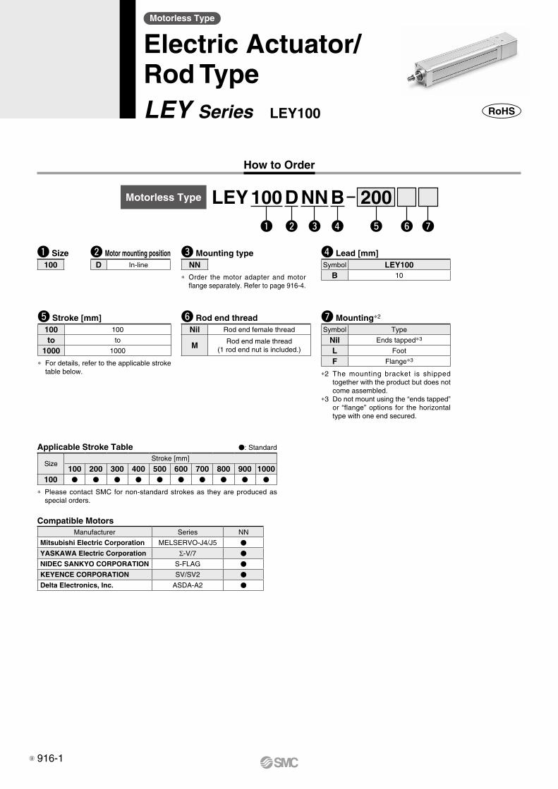
How to Order
Motorless Type
Electric Actuator/Rod TypeLEY Series LEY100
w ye r tq u
u Mounting*2
Symbol Type
Nil Ends tapped*3
L Foot
F Flange*3
*2 The mounting bracket is shipped together with the product but does not come assembled.
*3 Do not mount using the “ends tapped” or “flange” options for the horizontal type with one end secured.
t Stroke [mm]100 100
to to
1000 1000
* For details, refer to the applicable stroke table below.
r Lead [mm]Symbol LEY100
B 10
y Rod end threadNil Rod end female thread
M Rod end male thread(1 rod end nut is included.)
q Size100
w Motor mounting positionD In-line
Applicable Stroke Table V: Standard
SizeStroke [mm]
100 200 300 400 500 600 700 800 900 1000100 V V V V V V V V V V
* Please contact SMC for non-standard strokes as they are produced as special orders.
e Mounting typeNN
* Order the motor adapter and motor flange separately. Refer to page 916-4.
Motorless Type LEY 100 D NN B 200
Compatible MotorsManufacturer Series NN
Mitsubishi Electric Corporation MELSERVO-J4/J5 V
YASKAWA Electric Corporation Σ-V/7 V
NIDEC SANKYO CORPORATION S-FLAG V
KEYENCE CORPORATION SV/SV2 V
Delta Electronics, Inc. ASDA-A2 V
916-1B

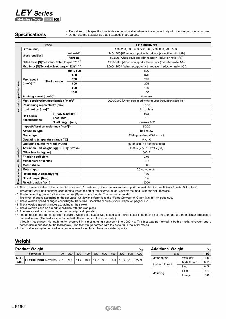
Specifications
Model LEY100DNNB
Act
uat
or
spec
ifica
tio
ns
Stroke [mm] 100, 200, 300, 400, 500, 600, 700, 800, 900, 1000
Work load [kg]Horizontal*1 240/1200 [When equipped with reducer (reduction ratio 1/5)]
Vertical 80/200 [When equipped with reducer (reduction ratio 1/5)]
Rated force [N]/Set value: Rated torque 87%*2 1100/5500 [When equipped with reducer (reduction ratio 1/5)]
Max. force [N]/Set value: Max. torque 192%*2 *3 2600/12000 [When equipped with reducer (reduction ratio 1/5)]
Max. speed[mm/s]*4 Stroke range
Up to 500 500
600 370
700 285
800 225
900 180
1000 150
Pushing speed [mm/s]*5 20 or less
Max. acceleration/deceleration [mm/s2] 3000/2000 [When equipped with reducer (reduction ratio 1/5)]
Positioning repeatability [mm] ±0.02
Lost motion [mm]*6 0.1 or less
Ball screw specifications
Thread size [mm] ø32
Lead [mm] 10
Shaft length [mm] Stroke + 202
Impact/Vibration resistance [m/s2]*7 50/20
Actuation type Ball screw
Guide type Sliding bushing (Piston rod)
Operating temperature range [°C] 5 to 40
Operating humidity range [%RH] 90 or less (No condensation)
Other
specifi
cation
s*8 Actuation unit weight [kg] (* [ST]: Stroke) 2.80 + (7.50 x 10⁻³) x [ST]
Other inertia [kg·cm] 0.047
Friction coefficient 0.05
Mechanical efficiency 0.9
Refer
ence
mot
or sp
ec.
Motor shape m80
Motor type AC servo motor
Rated output capacity [W] 750
Rated torque [N·m] 2.4
Rated rotation [rpm] 3000
*1 This is the max. value of the horizontal work load. An external guide is necessary to support the load (Friction coefficient of guide: 0.1 or less).The actual work load changes according to the condition of the external guide. Confirm the load using the actual device.
*2 The force setting range for the force control (Speed control mode, Torque control mode)The force changes according to the set value. Set it with reference to the “Force Conversion Graph (Guide)” on page 905.
*3 The allowable speed changes according to the stroke. Check the “Force–Stroke Graph” on page 905-1.*4 The allowable speed changes according to the stroke.*5 The allowable collision speed for collision with the workpiece*6 A reference value for correcting errors in reciprocal operation*7 Impact resistance: No malfunction occurred when the actuator was tested with a drop tester in both an axial direction and a perpendicular direction to
the lead screw. (The test was performed with the actuator in the initial state.)Vibration resistance: No malfunction occurred in a test ranging between 45 to 2000 Hz. The test was performed in both an axial direction and a perpendicular direction to the lead screw. (The test was performed with the actuator in the initial state.)
*8 Each value is only to be used as a guide to select a motor of the appropriate capacity.
* The values in this specifications table are the allowable values of the actuator body with the standard motor mounted.* Do not use the actuator so that it exceeds these values.
Weight
Product Weight [kg][kg] Additional WeightStroke [mm] 100 200 300 400 500 600 700 800 900 1000
Motor type LEY100DNNB Motorless 8.1 9.8 11.4 13.1 14.7 16.3 18.0 19.6 21.3 22.9
Size 100Motor option With lock 1.0
Rod end threadMale thread 0.11
Nut 0.05
MountingFoot 1.1
Flange 0.8
916-2
LEY SeriesMotorless Type 100Size
A
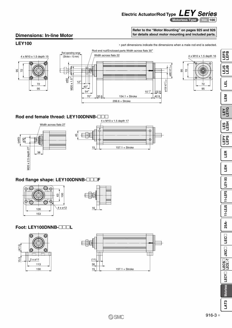
95
72
7295
Rod operating range(Stroke + 10 mm)
12∗
299.6 + Stroke
154.1 + Stroke32.670∗54∗
40∗
42.9
(32.9) ø19
h7 0
−
0.02
1
ø80
h7 0
−0
.030
7295
95
72
38
M20
x 2
.5 d
epth
27
ø30
(ø60
) 45
157.1 + Stroke
153
126
100
63
130
113
(47.
5)
157.1 + Stroke
4 x M10 x 1.5 depth 15
ø60
M20
x 1
.5∗
Rod end nut/Enclosed parts Width across flats 30∗
Width across flats 22
10 +0.2 0
4 x M10 x 1.5 depth 16
4 x M10 x 1.5 depth 17
15
Width across flats 27
4 x ø12 16
15.5 2 x ø11 (11)
30
15
Dimensions: In-line Motor
LEY100
Rod end female thread: LEY100DNNB-mmm
Rod flange shape: LEY100DNNB-mmmF
Foot: LEY100DNNB-mmmL
* part dimensions indicate the dimensions when a male rod end is selected.
Refer to the “Motor Mounting” on pages 925 and 926 for details about motor mounting and included parts.
916-3
Electric Actuator/Rod Type LEY SeriesMotorless Type 100Size
LE
FS
LE
FB
LE
LL
EJS
LE
JBL
EM
LE
YL
EY
GL
ES
LE
SH
LE
PY
LE
PS
LE
RL
EH
LEY-
X511
-LEF
S11
-LEJ
S25
A-
Moto
rless
LEC
Y�LE
CS
�LE
CS�-
TJX
C�
LE
C�
LA
T3
A
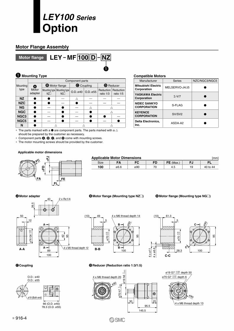
LEY100 Series
Option
Motor Flange Assembly
q
Motor flange LEY MF NZD100
Compatible MotorsManufacturer Series NZC/NGC3/NGC5
Mitsubishi Electric Corporation
MELSERVO-J4/J5 V
YASKAWA Electric Corporation Σ-V/7 V
NIDEC SANKYO CORPORATION
S-FLAG V
KEYENCE CORPORATION
SV/SV2 V
Delta Electronics,Inc.
ASDA-A2 V
CCoupling DReducer (Reduction ratio 1:3/1:5)
AMotor adapter BMotor flange (Mounting type NG�)BMotor flange (Mounting type NZ�)
O.D.: ø40O.D.: ø55
66 (O.D. ø40)78.3 (O.D. ø55)
4 x M6 thread depth 20
ø70
h7
0
−0.
030
ø19
h6
0
−0.
013
30
145.5
95.5
254 x M6 thread depth 13
ø70 G7 +0.040 +0.010 depth 6
ø19 G7 +0.028 +0.007 depth 50
ø90
ø90
ø19 (Both end)
A-AC
B-B
C-C
A
A
B
B C
100
95
ø90
5
ø70
+0.
06
+0.
03
28.3
61.3(10)
4 x
ø6.
6
4 x
ø11
95
100
ø90
4 x M6 thread depth 14
ø70
+0.
06
+0.
03
5
49(10)
2 x Rc1/440
26.5
12
50
ø76
G6
+0.0
29
+0.0
10
9542
4 x M5 thread depth 12
100
89
FC øF
J
FLFE
øF
D
FA
Applicable motor dimensions
Applicable Motor Dimensions [mm]
Size FA FC FD FE (Max.) FJ FL100 ø6.6 ø90 70 4.5 19 40 to 44
q Mounting Type
Mounting type
Component parts
A Motor
adapter
B Motor flange C Coupling D Reducer
Mounting type NZm
Mounting type NGm O.D. ø40 O.D. ø55
Reduction ratio 1/3
Reduction ratio 1/5
NZ V V — — — —
NZC V V — V — — —
NG V — V — NGC V — V — V NGC3 V — V — V V —
NGC5 V — V — V — V
N V
∗ The parts marked with a V are component parts. The parts marked with a should be prepared by the customer as necessary.
∗ Component parts A, B, C, and D come with mounting screws.∗ The motor mounting screws should be provided by the customer.
916-4B
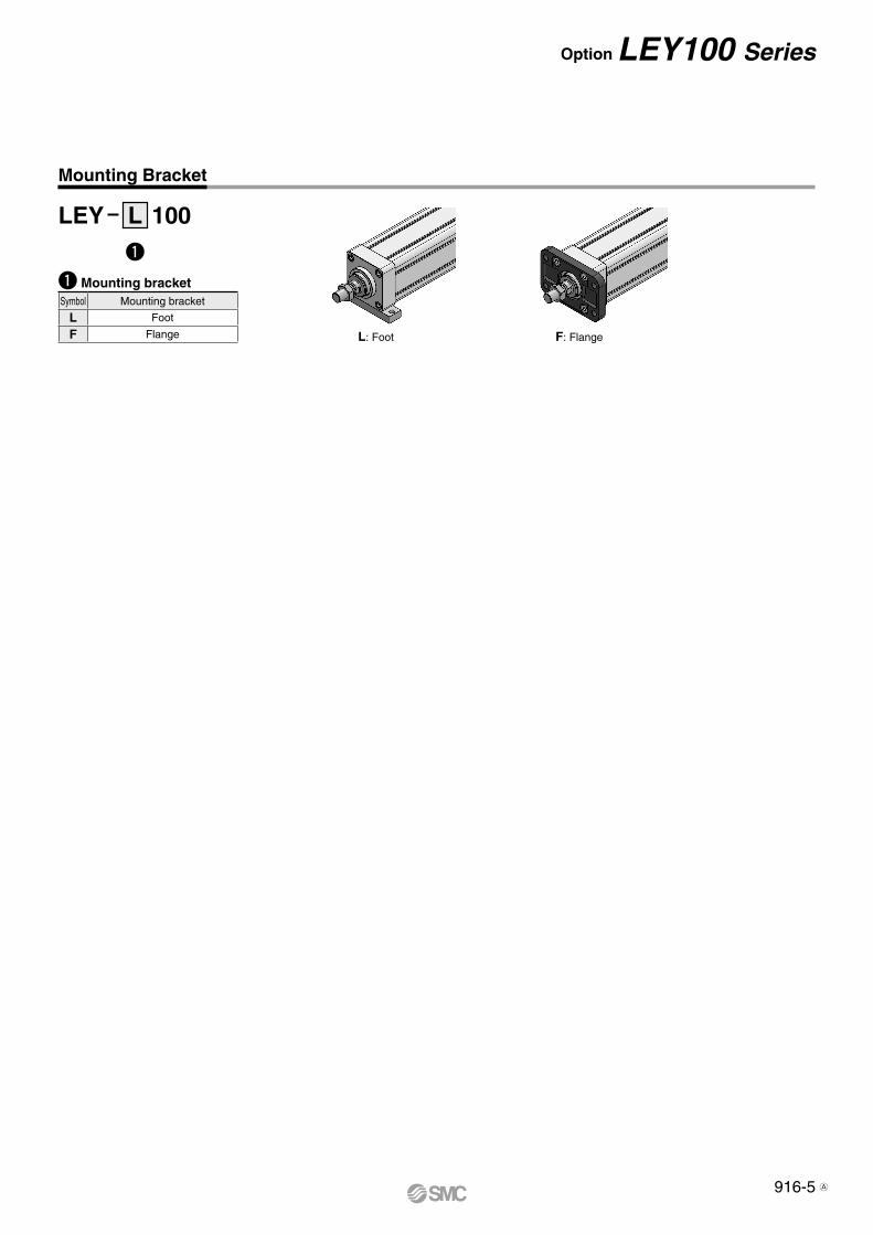
Option LEY100 Series
Mounting Bracket
q
q Mounting bracketSymbol Mounting bracket
L Foot
F Flange
LEY L 100
L: Foot F: Flange
916-5 A
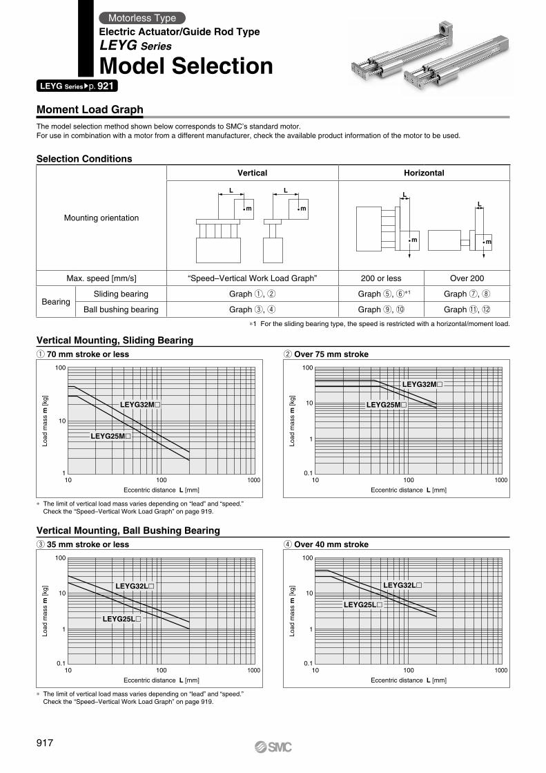
L L
m mL
m
L
m
Eccentric distance L [mm]
Load
mas
s m
[kg]
0.1
1
100
10
10 100
LEYG32M�
LEYG25M�
1000
Eccentric distance L [mm]
Load
mas
s m
[kg]
0.1
1
100
10
10 100
LEYG32L�
LEYG25L�
1000
Eccentric distance L [mm]
Load
mas
s m
[kg]
0.1
1
100
10
10 100
LEYG32L�
LEYG25L�
1000
Eccentric distance L [mm]
Load
mas
s m
[kg]
1
100
10
10 100
LEYG32M�
LEYG25M�
1000
Moment Load Graph
Selection Conditions
Vertical Mounting, Sliding Bearingq 70 mm stroke or less w Over 75 mm stroke
Vertical Mounting, Ball Bushing Bearinge 35 mm stroke or less r Over 40 mm stroke
∗ The limit of vertical load mass varies depending on “lead” and “speed.” Check the “Speed–Vertical Work Load Graph” on page 919.
∗ The limit of vertical load mass varies depending on “lead” and “speed.” Check the “Speed–Vertical Work Load Graph” on page 919.
∗1 For the sliding bearing type, the speed is restricted with a horizontal/moment load.
Mounting orientation
Vertical Horizontal
Max. speed [mm/s] “Speed–Vertical Work Load Graph” 200 or less Over 200
BearingSliding bearing Graph q, w Graph t, y∗1 Graph u, i
Ball bushing bearing Graph e, r Graph o, !0 Graph !1, !2
LEYG Seriessp. 921
Motorless TypeElectric Actuator/Guide Rod TypeLEYG Series
Model Selection
The model selection method shown below corresponds to SMC’s standard motor.For use in combination with a motor from a different manufacturer, check the available product information of the motor to be used.
917
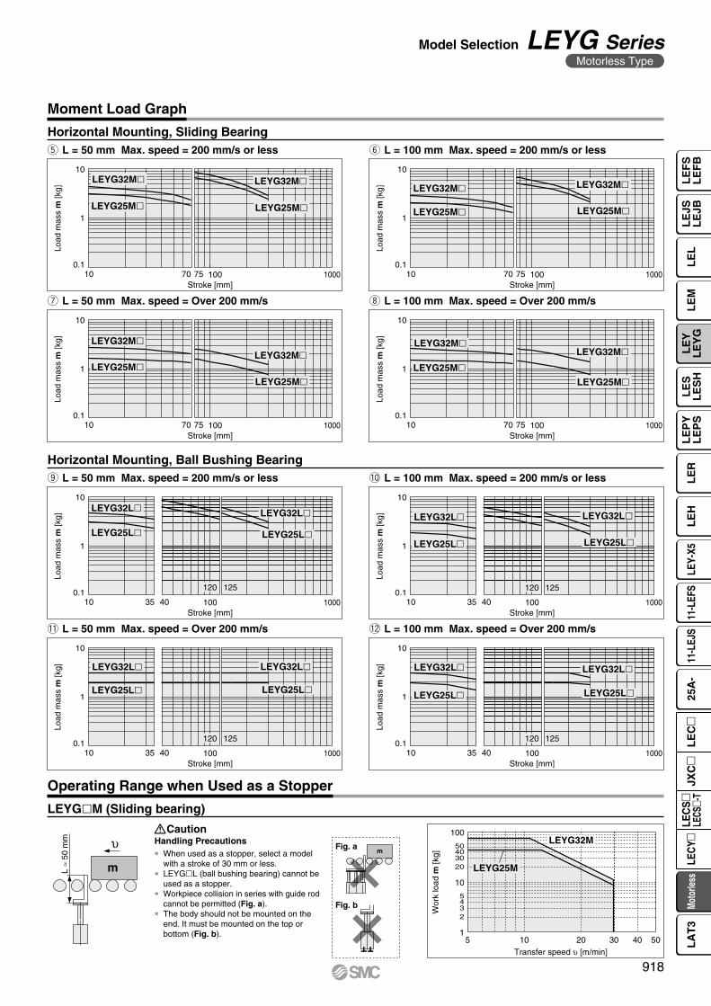
m
υ
L ≈
50 m
m
m
Transfer speed υ [m/min]
Wor
k lo
ad m
[kg]
504020 30105
100
50403020
10
5432
1
LEYG25M
LEYG32M
LEYG32M� LEYG32M�
LEYG25M� LEYG25M�
Load
mas
s m
[kg]
0.1
1
10
Stroke [mm]100 10007010 75
LEYG32M�
LEYG25M�LEYG32M�
LEYG25M�
Load
mas
s m
[kg]
0.1
1
10
Stroke [mm]100 10007010 75
LEYG32M�
LEYG25M�
LEYG32M�
LEYG25M�
Load
mas
s m
[kg]
0.1
1
10
Stroke [mm]100 10007010 75
LEYG32M�
LEYG25M�
LEYG32M�
LEYG25M�Lo
ad m
ass
m [k
g]
0.1
1
10
Stroke [mm]100 10007010 75
LEYG32L� LEYG32L�
LEYG25L� LEYG25L�
Load
mas
s m
[kg]
0.1
1
10
Stroke [mm]100 1000403510
120 125
LEYG32L� LEYG32L�
LEYG25L� LEYG25L�
Load
mas
s m
[kg]
0.1
1
10
Stroke [mm]100 1000403510
120 125
LEYG32L� LEYG32L�
LEYG25L� LEYG25L�
Load
mas
s m
[kg]
0.1
1
10
Stroke [mm]100 1000403510
120 125
LEYG32L� LEYG32L�
LEYG25L� LEYG25L�
Load
mas
s m
[kg]
0.1
1
10
Stroke [mm]100 1000403510
120 125
Fig. a
Fig. b
LEYGlM (Sliding bearing)
Caution
Operating Range when Used as a Stopper
Horizontal Mounting, Sliding Bearingt L = 50 mm Max. speed = 200 mm/s or less
u L = 50 mm Max. speed = Over 200 mm/s i L = 100 mm Max. speed = Over 200 mm/s
Handling Precautions∗ When used as a stopper, select a model
with a stroke of 30 mm or less.∗ LEYGlL (ball bushing bearing) cannot be
used as a stopper.∗ Workpiece collision in series with guide rod
cannot be permitted (Fig. a).∗ The body should not be mounted on the
end. It must be mounted on the top or bottom (Fig. b).
y L = 100 mm Max. speed = 200 mm/s or less
Horizontal Mounting, Ball Bushing Bearingo L = 50 mm Max. speed = 200 mm/s or less
!1 L = 50 mm Max. speed = Over 200 mm/s !2 L = 100 mm Max. speed = Over 200 mm/s
!0 L = 100 mm Max. speed = 200 mm/s or less
Moment Load Graph
918
Model Selection LEYG SeriesMotorless Type
LE
FS
LE
FB
LE
LL
EJS
LE
JBL
EM
LE
YL
EY
GL
ES
LE
SH
LE
PY
LE
PS
LE
RL
EH
LEY-
X511
-LEF
S11
-LEJ
S25
A-
Moto
rless
LEC
Y�LE
CS
�LE
CS�-
TJX
C�
LE
C�
LA
T3
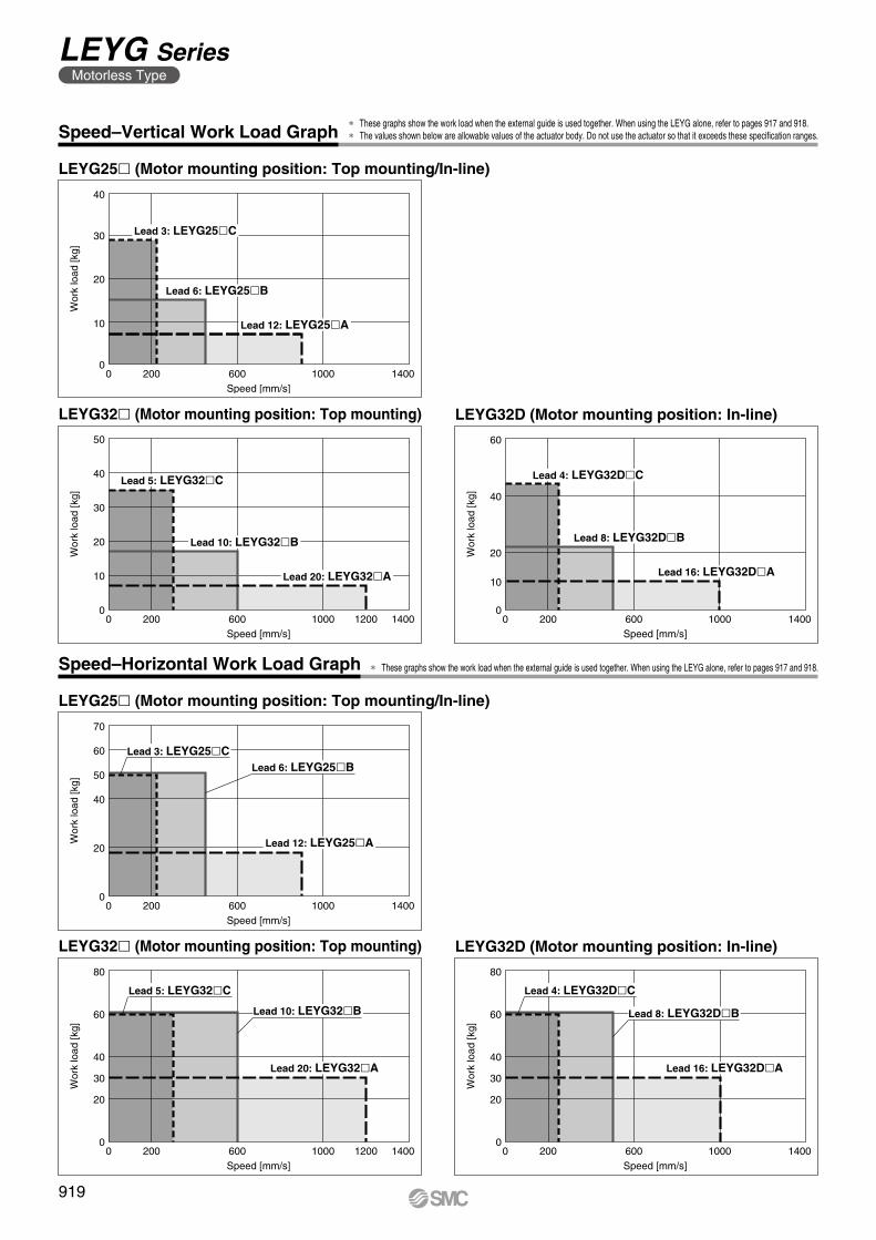
0 200 600 1000 1400Speed [mm/s]
Wor
k lo
ad [k
g]
0
10
40
30
20
Lead 3: LEYG25�C
Lead 6: LEYG25�B
Lead 12: LEYG25�A
Lead 5: LEYG32�C
Lead 10: LEYG32�B
Lead 20: LEYG32�A
0 200 600 1000 14001200Speed [mm/s]
Wor
k lo
ad [k
g]
0
10
50
30
40
20
0 200 600 1000 1400Speed [mm/s]
Wor
k lo
ad [k
g]
0
10
60
40
20
Lead 4: LEYG32D�C
Lead 8: LEYG32D�B
Lead 16: LEYG32D�A
0 200 600 1000 1400Speed [mm/s]
Wor
k lo
ad [k
g]
0
20
70
50
60
40
Lead 12: LEYG25�A
Lead 3: LEYG25�CLead 6: LEYG25�B
Lead 20: LEYG32�A
0 200 600 1000 14001200Speed [mm/s]
Wor
k lo
ad [k
g]
0
20
80
60
40
30
Lead 5: LEYG32�C
Lead 10: LEYG32�B
Lead 16: LEYG32D�A
0 200 600 1000 1400Speed [mm/s]
Wor
k lo
ad [k
g]
0
20
80
60
40
30
Lead 4: LEYG32D�C
Lead 8: LEYG32D�B
Speed–Vertical Work Load Graph
LEYG25l (Motor mounting position: Top mounting/In-line)
LEYG32l (Motor mounting position: Top mounting) LEYG32D (Motor mounting position: In-line)
Speed–Horizontal Work Load Graph
LEYG25l (Motor mounting position: Top mounting/In-line)
LEYG32l (Motor mounting position: Top mounting) LEYG32D (Motor mounting position: In-line)
* These graphs show the work load when the external guide is used together. When using the LEYG alone, refer to pages 917 and 918.* The values shown below are allowable values of the actuator body. Do not use the actuator so that it exceeds these specification ranges.
* These graphs show the work load when the external guide is used together. When using the LEYG alone, refer to pages 917 and 918.
919
LEYG SeriesMotorless Type
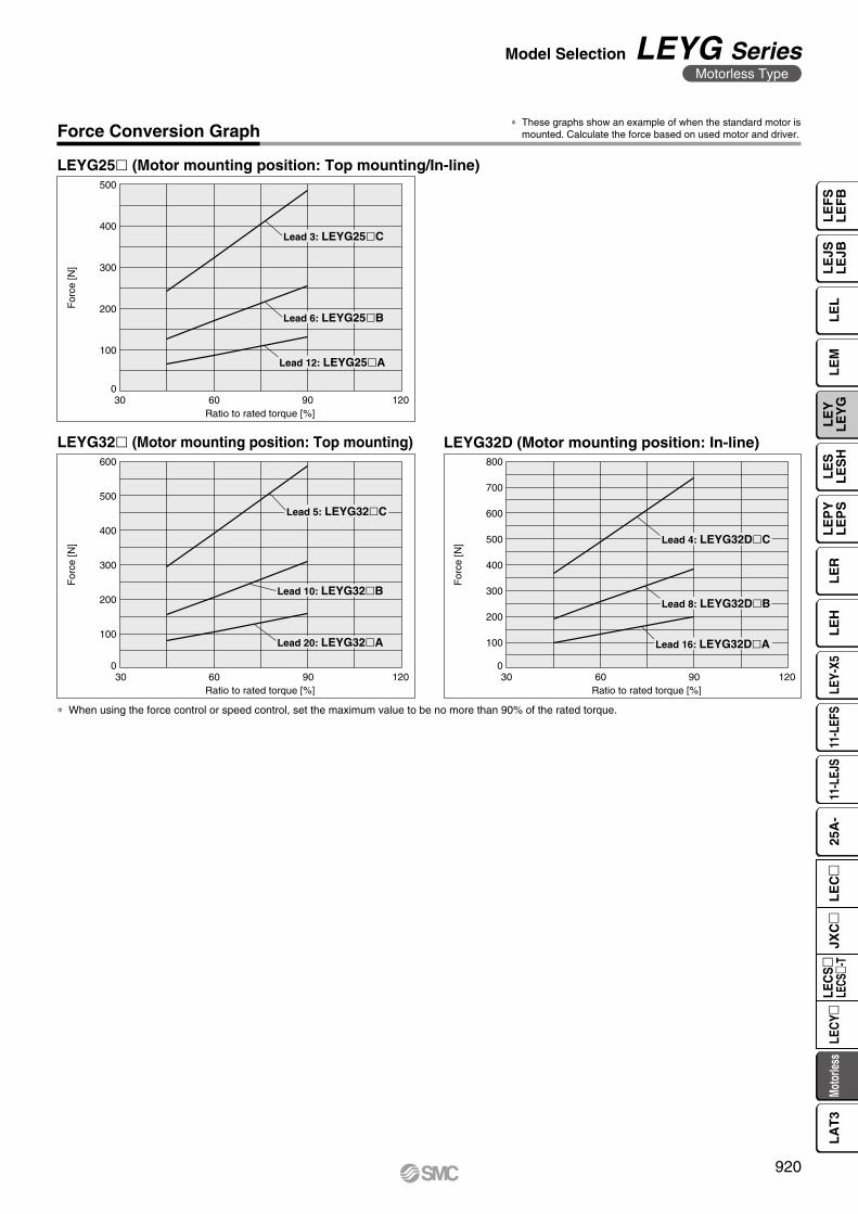
For
ce [N
]
Ratio to rated torque [%]
500
400
300
200
100
06030 12090
Lead 3: LEYG25�C
Lead 6: LEYG25�B
Lead 12: LEYG25�A
For
ce [N
]
Ratio to rated torque [%]
800
700
600
500
400
300
200
100
06030 12090
Lead 4: LEYG32D�C
Lead 8: LEYG32D�B
Lead 16: LEYG32D�A
For
ce [N
]
Ratio to rated torque [%]
600
500
400
300
200
100
06030 12090
Lead 5: LEYG32�C
Lead 10: LEYG32�B
Lead 20: LEYG32�A
Force Conversion Graph
LEYG25l (Motor mounting position: Top mounting/In-line)
LEYG32D (Motor mounting position: In-line)LEYG32l (Motor mounting position: Top mounting)
* When using the force control or speed control, set the maximum value to be no more than 90% of the rated torque.
* These graphs show an example of when the standard motor is mounted. Calculate the force based on used motor and driver.
920
Model Selection LEYG SeriesMotorless Type
LE
FS
LE
FB
LE
LL
EJS
LE
JBL
EM
LE
YL
EY
GL
ES
LE
SH
LE
PY
LE
PS
LE
RL
EH
LEY-
X511
-LEF
S11
-LEJ
S25
A-
Moto
rless
LEC
Y�LE
CS
�LE
CS�-
TJX
C�
LE
C�
LA
T3
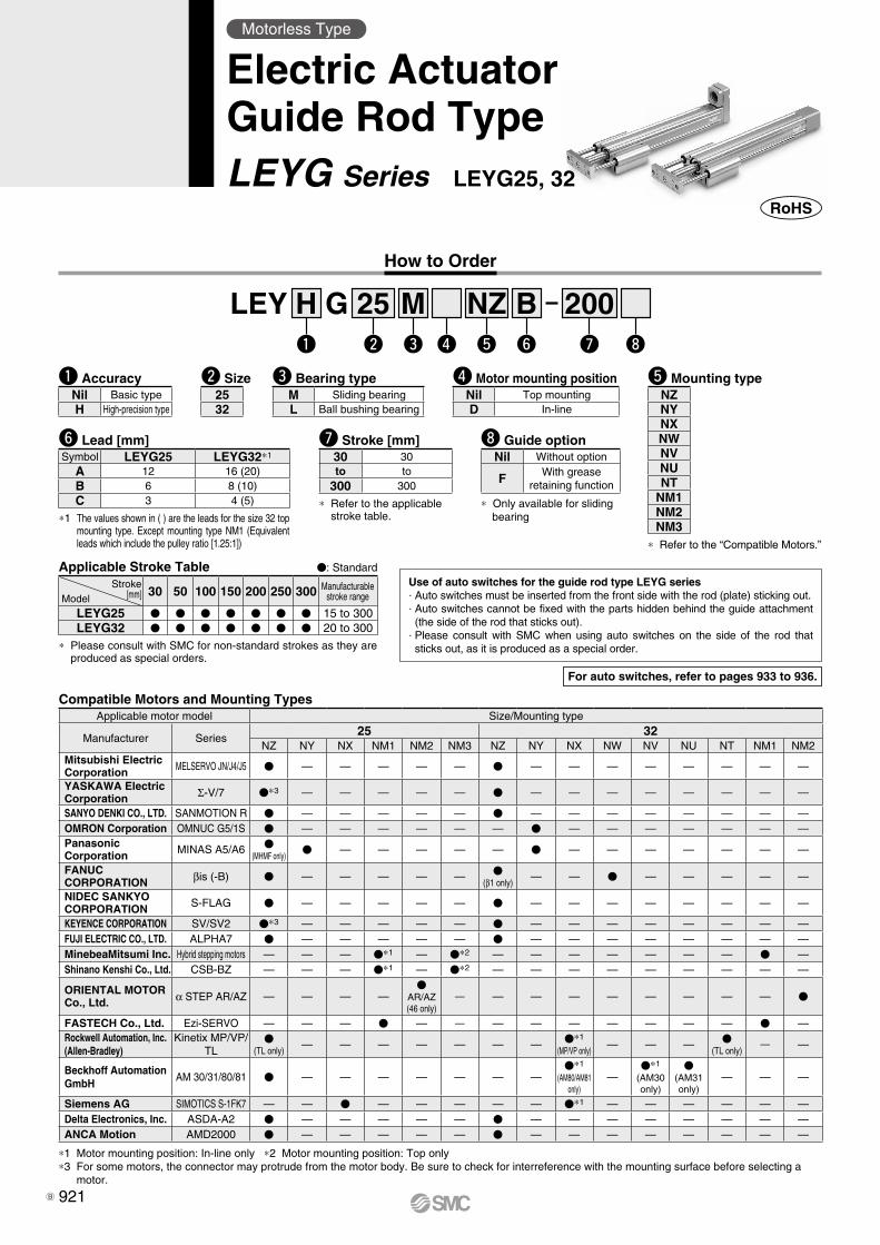
25 200Bw
LEY Gre t y u i
NZMq
H
i Guide option
* Only available for sliding bearing
Nil Without option
F With grease retaining function
y Lead [mm]
*1 The values shown in ( ) are the leads for the size 32 top mounting type. Except mounting type NM1 (Equivalent leads which include the pulley ratio [1.25:1])
Symbol LEYG25 LEYG32*1
A 12 16 (20)B 6 8 (10)C 3 4 (5) * Refer to the applicable
stroke table.
u Stroke [mm]30 30to to
300 300
Use of auto switches for the guide rod type LEYG series⋅ Auto switches must be inserted from the front side with the rod (plate) sticking out.⋅ Auto switches cannot be fixed with the parts hidden behind the guide attachment (the side of the rod that sticks out).
⋅ Please consult with SMC when using auto switches on the side of the rod that sticks out, as it is produced as a special order.
How to Order
Applicable Stroke Table V: Standard
* Please consult with SMC for non-standard strokes as they are produced as special orders.
Stroke[mm]Model
30 50 100 150 200 250 300 Manufacturable stroke range
LEYG25 V V V V V V V 15 to 300LEYG32 V V V V V V V 20 to 300
w Size r Motor mounting positione Bearing type t Mounting type
* Refer to the “Compatible Motors.”
q AccuracyNil Basic typeH High-precision type
M Sliding bearingL Ball bushing bearing
Nil Top mountingD In-line
2532
For auto switches, refer to pages 933 to 936.
Motorless Type
Electric ActuatorGuide Rod TypeLEYG Series LEYG25, 32
NZNYNXNWNVNUNT
NM1NM2NM3
Compatible Motors and Mounting TypesApplicable motor model Size/Mounting type
Manufacturer Series25 32
NZ NY NX NM1 NM2 NM3 NZ NY NX NW NV NU NT NM1 NM2Mitsubishi ElectricCorporation MELSERVO JN/J4/J5 V — — — — — V — — — — — — — —
YASKAWA Electric Corporation Σ-V/7 V*3 — — — — — V — — — — — — — —
SANYO DENKI CO., LTD. SANMOTION R V — — — — — V — — — — — — — —OMRON Corporation OMNUC G5/1S V — — — — — — V — — — — — — —PanasonicCorporation MINAS A5/A6 V
(MHMF only)V — — — — — V — — — — — — —
FANUC CORPORATION βis (-B) V — — — — — V
(β1 only)— — V — — — — —
NIDEC SANKYO CORPORATION S-FLAG V — — — — — V — — — — — — — —
KEYENCE CORPORATION SV/SV2 V*3 — — — — — V — — — — — — — —FUJI ELECTRIC CO., LTD. ALPHA7 V — — — — — V — — — — — — — —MinebeaMitsumi Inc. Hybrid stepping motors — — — V*1 — V*2 — — — — — — — V —Shinano Kenshi Co., Ltd. CSB-BZ — — — V*1 — V*2 — — — — — — — — —
ORIENTAL MOTOR Co., Ltd. α STEP AR/AZ — — — —
VAR/AZ(46 only)
— — — — — — — — — V
FASTECH Co., Ltd. Ezi-SERVO — — — V — — — — — — — — — V —Rockwell Automation, Inc.(Allen-Bradley)
Kinetix MP/VP/TL
V(TL only)
— — — — — — — V*1
(MP/VP only)— — — V
(TL only)— —
Beckhoff AutomationGmbH
AM 30/31/80/81 V — — — — — — —V*1
(AM80/AM81 only)
—V*1
(AM30 only)
V(AM31 only)
— — —
Siemens AG SIMOTICS S-1FK7 — — V — — — — — V*1 — — — — — —Delta Electronics, Inc. ASDA-A2 V — — — — — V — — — — — — — —ANCA Motion AMD2000 V — — — — — V — — — — — — — —
*1 Motor mounting position: In-line only *2 Motor mounting position: Top only*3 For some motors, the connector may protrude from the motor body. Be sure to check for interreference with the mounting surface before selecting a
motor.
921B
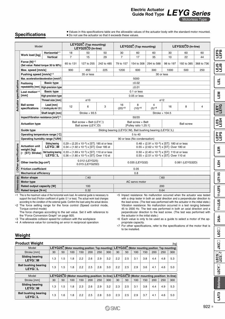
Specifications
Weight
[kg]Product Weight
∗1 This is the maximum value of the horizontal work load. An external guide is necessary to support the load (Friction coefficient of guide: 0.1 or less). The actual work load changes according to the condition of the external guide. Confirm the load using the actual device.
∗2 The force setting range for the force control (Speed control mode, Torque control mode)The force changes according to the set value. Set it with reference to the “Force Conversion Graph” on page 920.
∗3 The allowable collision speed for collision with the workpiece∗4 A reference value for correcting an error in reciprocal operation
¡Values in this specifications table are the allowable values of the actuator body with the standard motor mounted.¡Do not use the actuator so that it exceeds these values.
∗5 Impact resistance: No malfunction occurred when the actuator was tested with a drop tester in both an axial direction and a perpendicular direction to the lead screw. (The test was performed with the actuator in the initial state.)Vibration resistance: No malfunction occurred in a test ranging between 45 to 2000 Hz. The test was performed in both an axial direction and a perpendicular direction to the lead screw. (The test was performed with the actuator in the initial state.)
∗6 Each value is only to be used as a guide to select a motor of the ap-propriate capacity.
∗7 For other specifications, refer to the specifications of the motor that is to be installed.
ModelLEYG25M
L (Top mounting)LEYG25M
LD (In-line)LEYG32M
L (Top mounting) LEYG32M LD (In-line)
Act
uat
or
spec
ifica
tio
ns
Work load [kg]Horizontal∗1 18 50 50 30 60 60 30 60 60
Vertical 7 15 29 7 17 35 10 22 44
Force [N]∗2
(Set value: Rated torque 30 to 90%)65 to 131 127 to 255 242 to 485 79 to 157 154 to 308 294 to 588 98 to 197 192 to 385 368 to 736
Max. speed [mm/s] 900 450 225 1200 600 300 1000 500 250
Pushing speed [mm/s]∗3 35 or less 30 or less
Max. acceleration/deceleration [mm/s2] 5000
Positioning repeatability [mm]
Basic type ±0.02
High-precision type ±0.01
Lost motion∗4
[mm]Basic type 0.1 or less
High-precision type 0.05 or less
Ball screw specifications
Thread size [mm] ø10 ø12
Lead [mm]∗8 (including pulley ratio 1.25:1)
12 6 316
(20)∗88
(10)∗84
(5)∗8 16 8 4
Shaft length [mm] Stroke + 93.5 Stroke + 104.5
Impact/Vibration resistance [m/s2]∗5 50/20
Actuation typeBall screw + Belt (LEYl)
Ball screw (LEYlD)Ball screw + Belt
[Pulley ratio 1.25:1]Ball screw
Guide type Sliding bearing (LEYGlM), Ball bushing bearing (LEYGlL)
Operating temperature range [°C] 5 to 40
Operating humidity range [%RH] 90 or less (No condensation)
Oth
er s
pec
ifica
tio
ns
Actuation unit weight [kg](∗ [ST]: Stroke)
Sliding bearingLEYGlM
0.29 + (2.20 x 10⁻³) x [ST]: 185 st or less0.34 + (1.92 x 10⁻³) x [ST]: Over 185 st
0.48 + (2.91 x 10⁻³) x [ST]: 180 st or less0.55 + (2.62 x 10⁻³) x [ST]: Over 180 st
Ball bushing bearingLEYGlL
0.33 + (1.69 x 10⁻³) x [ST]: 110 st or less0.36 + (1.80 x 10⁻³) x [ST]: Over 110 st
0.50 + (2.40 x 10⁻³) x [ST]: 110 st or less0.55 + (2.51 x 10⁻³) x [ST]: Over 110 st
Other inertia [kg·cm2]0.012 (LEYG25)
0.015 (LEYG25D)0.035 (LEYG32) 0.061 (LEYG32D)
Friction coefficient 0.05
Mechanical efficiency 0.8
Refere
nce mo
tor sp
ec. Motor shape l40 l60
Motor type AC servo motor
Rated output capacity [W] 100 200
Rated torque [N·m] 0.32 0.64
Model LEYG25M LD (Motor mounting position: In-line) LEYG32M
LD (Motor mounting position: In-line)Stroke [mm] 30 50 100 150 200 250 300 30 50 100 150 200 250 300
Sliding bearingLEYGlM 1.3 1.5 1.8 2.3 2.6 2.9 3.2 2.3 2.5 3.1 3.8 4.4 4.9 5.3
Ball bushing bearingLEYGlL 1.3 1.6 1.8 2.2 2.5 2.8 3.0 2.3 2.5 2.9 3.7 4.1 4.6 5.0
Model LEYG25M L (Motor mounting position: Top mounting) LEYG32M
L (Motor mounting position: Top mounting)Stroke [mm] 30 50 100 150 200 250 300 30 50 100 150 200 250 300
Sliding bearingLEYGlM 1.3 1.5 1.8 2.2 2.6 2.9 3.2 2.2 2.5 3.1 3.8 4.4 4.8 5.3
Ball bushing bearingLEYGlL 1.3 1.5 1.8 2.2 2.5 2.8 3.0 2.2 2.5 2.9 3.6 4.1 4.6 5.0
∗6
∗7
922
Electric ActuatorGuide Rod Type LEYG Series
Motorless Type
LE
FS
LE
FB
LE
LL
EJS
LE
JBL
EM
LE
YL
EY
GL
ES
LE
SH
LE
PY
LE
PS
LE
RL
EH
LEY-
X511
-LEF
S11
-LEJ
S25
A-
Moto
rless
LEC
Y�LE
CS
�LE
CS�-
TJX
C�
LE
C�
LA
T3
B
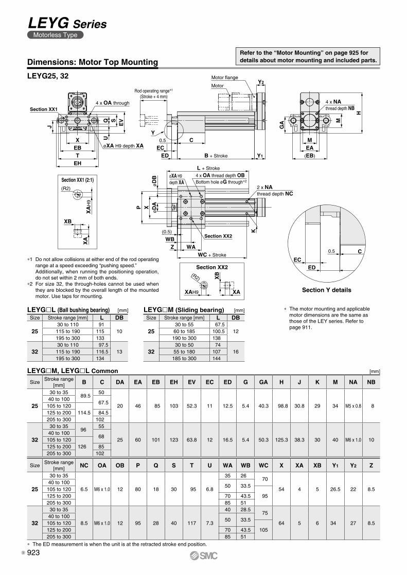
C
ECED
0.5
Motor flange
Motor
C
Y1
Y2
ECED
Rod operating range∗1
(Stroke + 4 mm)
0.5
B + Stroke
Y
K
H
4 x NAthread depth NB
M
(EB)
EAM
GAEVSQ
U
EHT
EBX
J
2 x NAthread depth NC
WC + Stroke
Section XX2
WAWB
(0.5)
Z
P
øD
BX
øD
A
L + Stroke
øXA H9depth XA
4 x OA thread depth OBBottom hole øG through∗2
Section XX14 x OA through
øXA H9 depth XA
XA
H9
(R2)
XB
XA
XA
XB(R2)
XAH9 Section Y details
Section XX1 (2:1)
[mm]LEYGlL (Ball bushing bearing)
LEYGlM, LEYGlL Common
[mm]LEYGlM (Sliding bearing)
* The ED measurement is when the unit is at the retracted stroke end position.
Section XX2
[mm]
SizeStroke range
[mm] NC OA OB P Q S T U WA WB WC X XA XB Y1 Y2 Z
25
30 to 35
6.5 M6 x 1.0 12 80 18 30 95 6.8
35 26 70
54 4 5 26.5 22 8.540 to 100
50 33.5105 to 120
95125 to 200 70 43.5205 to 300 85 51
32
30 to 35
8.5 M6 x 1.0 12 95 28 40 117 7.3
40 28.5 75
64 5 6 34 27 8.540 to 100
50 33.5105 to 120
105125 to 200 70 43.5205 to 300 85 51
Size Stroke range [mm] L DB
2530 to 55 67.5
1260 to 185 100.5190 to 300 138
3230 to 50 74
1655 to 180 107185 to 300 144
SizeStroke range
[mm] B C DA EA EB EH EV EC ED G GA H J K M NA NB
25
30 to 3589.5
50
20 46 85 103 52.3 11 12.5 5.4 40.3 98.8 30.8 29 34 M5 x 0.8 840 to 100
67.5105 to 120
114.5125 to 200 84.5205 to 300 102
32
30 to 3596
55
25 60 101 123 63.8 12 16.5 5.4 50.3 125.3 38.3 30 40 M6 x 1.0 1040 to 100
68105 to 120
126125 to 200 85205 to 300 102
Size Stroke range [mm] L DB
2530 to 110 91
10115 to 190 115195 to 300 133
3230 to 110 97.5
13115 to 190 116.5195 to 300 134
* The motor mounting and applicable motor dimensions are the same as those of the LEY series. Refer to page 911.
Dimensions: Motor Top Mounting
LEYG25, 32
Refer to the “Motor Mounting” on page 925 for details about motor mounting and included parts.
*1 Do not allow collisions at either end of the rod operating range at a speed exceeding “pushing speed.”Additionally, when running the positioning operation, do not set within 2 mm of both ends.
*2 For size 32, the through-holes cannot be used when they are blocked by the overall length of the mounted motor. Use taps for mounting.
923
LEYG SeriesMotorless Type
B
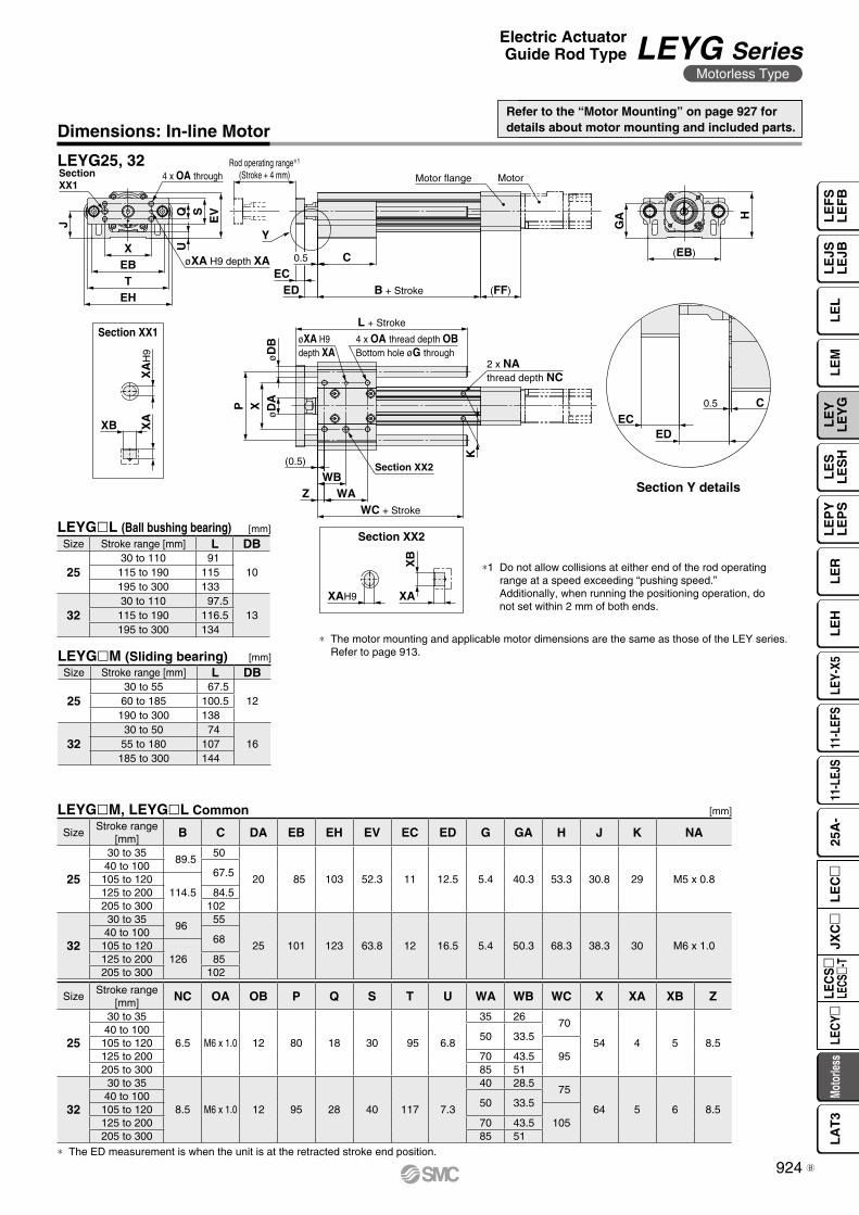
CEC
ED
0.5
MotorMotor flange
(FF)
CEC
ED
Rod operating range∗1
(Stroke + 4 mm)
0.5
B + Stroke
Y
EVSQ
U
J
EHT
EBX
L + Stroke
øD
B
P
øD
AX
WC + Stroke
WAZ
(0.5)K
SectionXX1
øXA H9 depth XA
4 x OA through
4 x OA thread depth OBBottom hole øG through
øXA H9depth XA
Section XX2
2 x NAthread depth NC
WB
H
(EB)
GA
XA
H9
XB XA
XA
XB
XAH9
Section Y details
Section XX2
Section XX1
[mm]LEYGlM (Sliding bearing)
* The ED measurement is when the unit is at the retracted stroke end position.
SizeStroke range
[mm] NC OA OB P Q S T U WA WB WC X XA XB Z
25
30 to 35
6.5 M6 x 1.0 12 80 18 30 95 6.8
35 26 70
54 4 5 8.540 to 100
50 33.5105 to 120
95125 to 200 70 43.5205 to 300 85 51
32
30 to 35
8.5 M6 x 1.0 12 95 28 40 117 7.3
40 28.5 75
64 5 6 8.540 to 100
50 33.5105 to 120
105125 to 200 70 43.5205 to 300 85 51
LEYGlM, LEYGlL Common [mm]
SizeStroke range
[mm] B C DA EB EH EV EC ED G GA H J K NA
25
30 to 3589.5
50
20 85 103 52.3 11 12.5 5.4 40.3 53.3 30.8 29 M5 x 0.840 to 100
67.5105 to 120
114.5125 to 200 84.5205 to 300 102
32
30 to 3596
55
25 101 123 63.8 12 16.5 5.4 50.3 68.3 38.3 30 M6 x 1.040 to 100
68105 to 120
126125 to 200 85205 to 300 102
Size Stroke range [mm] L DB
2530 to 55 67.5
1260 to 185 100.5190 to 300 138
3230 to 50 74
1655 to 180 107185 to 300 144
Refer to the “Motor Mounting” on page 927 for details about motor mounting and included parts.
*1 Do not allow collisions at either end of the rod operating range at a speed exceeding “pushing speed.”Additionally, when running the positioning operation, do not set within 2 mm of both ends.
Dimensions: In-line Motor
LEYG25, 32
[mm]LEYGlL (Ball bushing bearing)Size Stroke range [mm] L DB
2530 to 110 91
10115 to 190 115195 to 300 133
3230 to 110 97.5
13115 to 190 116.5195 to 300 134
* The motor mounting and applicable motor dimensions are the same as those of the LEY series. Refer to page 913.
924
Electric ActuatorGuide Rod Type LEYG Series
Motorless Type
LE
FS
LE
FB
LE
LL
EJS
LE
JBL
EM
LE
YL
EY
GL
ES
LE
SH
LE
PY
LE
PS
LE
RL
EH
LEY-
X511
-LEF
S11
-LEJ
S25
A-
Moto
rless
LEC
Y�LE
CS
�LE
CS�-
TJX
C�
LE
C�
LA
T3
B
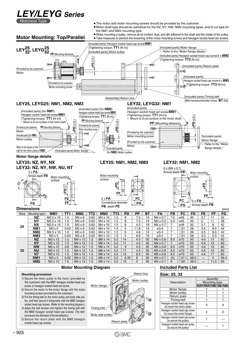
[Provided by the customer]Motor[Included parts] (for NM1)Motor pulley
Refer to the figure on the right for the motor pulley of NM2. [Included parts] Motor flange
[Included parts](for NM2) Motor pulley
øP
D (
I.D.)
PP (Mounting distance)
øP
D (
I.D.)PP (Mounting distance)
[Provided by the customer]Motor mounting screw
[Included parts] (for NM2)Hexagon socket head cap screw/MM1(Tightening torque: TT1 [N·m])
[Included parts] (for NM1)Hexagon socket head set screw/MM1(Tightening torque: TT1 [N·m])∗ Mount to D-cut surface of the motor shaft.
[Included parts] Motor flange∗ Refer to the “Motor
flange details.”
[Provided by the customer]Motor
øP
D (
I.D.)
[Included parts] Hexagon socket head set screw/MM1(Tightening torque: TT1 [N·m])∗ Mount to D-cut surface of the motor shaft.
[Provided by the customer]Motor mounting screw
PP (Mounting distance)
[Included parts] Return plate
[Provided by the customer]Motor mounting screw
[Provided by the customer]Motor
PP (Mounting distance)[Included parts] Motor pulley
[Included parts] Hexagon socket head cap screw/MM1(Tightening torque: TT1 [N·m])
øPD
(I.D
.) [Included parts] Hexagon socket head cap screw/2 x MM2(Tightening torque: TT2 [N·m])
[Included parts] Timing belt(Belt tension/tensile force: BT [N])
[Assembly] Return box
[Included parts] Hexagon socket head cap screw/4 x MM3 (Tightening torque: TT3 [N·m])
[Included parts] Motor flange∗ Refer to the “Motor flange details.”
Motor flange
Timing belt
Return box
Motor pulley
Body side pulley
Return plate
Motor flange details
[mm]�FGFC
FF
øF
D2 x FAthread depth FB
2 x (M4 x 0.7)thread depth FB Motor mounting
surface
LEY32: NM1, NM2
FF
øF
D
FC�FG
Motor mounting surface
2 x FACounterbore diameter FB, depth FE
LEY25: NM1, NM2, NM3
45°
FC
FG FFFE
øF
D+
0.3
+0.
1
2 x FAthread depth FB Motor mounting
surface
LEY25: NZ, NY, NXLEY32: NZ, NY, NW, NU, NT
LEY25, LEYG25: NM1, NM2, NM3 LEY32, LEYG32: NM1
Dimensions
Motor Mounting: Top/Parallel
Mounting procedure1) Secure the motor pulley to the motor (provided by
the customer) with the MM1 hexagon socket head cap screw or hexagon socket head set screw.
2) Secure the motor to the motor flange with the motor mounting screws (provided by the customer).
3) Put the timing belt on the motor pulley and body side pul-ley, and then secure it temporarily with the MM2 hexagon socket head cap screws. (Refer to the mounting diagram.)
4) Apply the belt tension and tighten the timing belt with the MM2 hexagon socket head cap screws. (The refer-ence level is the elimination of the belt deflection.)
5) Secure the return plate with the MM3 hexagon socket head cap screws.
¡The motor and motor mounting screws should be provided by the customer.¡Motor shaft type should be cylindrical for the NZ, NY, NW, NM2 mounting types, and D-cut type for
the NM1 and NM3 mounting type.¡When mounting a pulley, remove all oil content, dust, and dirt adhered to the shaft and the inside of the pulley.¡Take measures to prevent the loosening of the motor mounting screws and hexagon socket head set screws.
Size: 25, 32
Motor Mounting Diagram
DescriptionQuantity
Mounting typeNZ/NY/NW/NT/NM2 NM1/NM3
Motor flange 1 1Motor pulley 1 1Return plate 1 1Timing belt 1 1
Hexagon socket head cap screw(to mount the return plate) 4 4
Hexagon socket head cap screw(to mount the motor flange) 2 2
Hexagon socket head cap screw(to secure the pulley) 1 —
Hexagon socket head set screw(to secure the pulley) — 1
LEY , LEYG 2532
2532
Size Mounting type MM1 TT1 MM2 TT2 MM3 TT3 PD PP BT FA FB FC FD FE FF FG
25
NZ M2.5 x 10 1.0 M3 x 8 0.63 M4 x 10 1.5 8 7.5 19 M4 x 0.7 7.5 ø46 30 3.7 11 42NY M2.5 x 10 1.0 M3 x 8 0.63 M4 x 10 1.5 8 7.5 19 M3 x 0.5 5.5 ø45 30 5 11 38NX M2.5 x 10 1.0 M3 x 8 0.63 M4 x 10 1.5 8 4.5 19 M4 x 0.7 7 ø46 30 3.7 8 42
NM1 M3 x 5 0.63 M3 x 8 0.63 M4 x 10 1.5 5 11.8 19 ø3.4 7 m31 28 3.5 8.5 42NM2 M2.5 x 10 1.0 M3 x 8 0.63 M4 x 10 1.5 6 4.8 19 ø3.4 7 m31 28 3.5 8.5 42NM3 M3 x 5 0.63 M3 x 8 0.63 M4 x 10 1.5 5 8.8 19 ø3.4 7 m31 28 3.5 5.5 42
32
NZ M3 x 12 1.5 M4 x 12 1.5 M6 x 14 5.2 14 4.5 30 M5 x 0.8 8.5 ø70 50 4.6 13 60NY M3 x 12 1.5 M4 x 12 1.5 M6 x 14 5.2 11 4.5 30 M4 x 0.7 7 ø70 50 4.6 13 60NW M4 x 12 3.6 M4 x 12 1.5 M6 x 14 5.2 9 4.5 30 M5 x 0.8 8.5 ø70 50 4.6 13 60NU M3 x 12 1.5 M4 x 12 1.5 M6 x 14 5.2 11 4.5 30 M5 x 0.8 8.5 ø70 50 4.6 13 60NT M3 x 12 1.5 M4 x 12 1.5 M6 x 14 5.2 12 8.5 30 M5 x 0.8 8.5 ø70 50 4.6 17 60
NM1 M3 x 5 0.63 M4 x 12 1.5 M6 x 14 5.2 6.35 8 30 M4 x 0.7 (5) m47.1 38.2 — 5 56.4NM2 M3 x 12 1.5 M4 x 12 1.5 M6 x 14 5.2 10 3 30 M4 x 0.7 8 m50 38.2 — 11.5 60
Included Parts List
925
LEY/LEYG SeriesMotorless Type
A
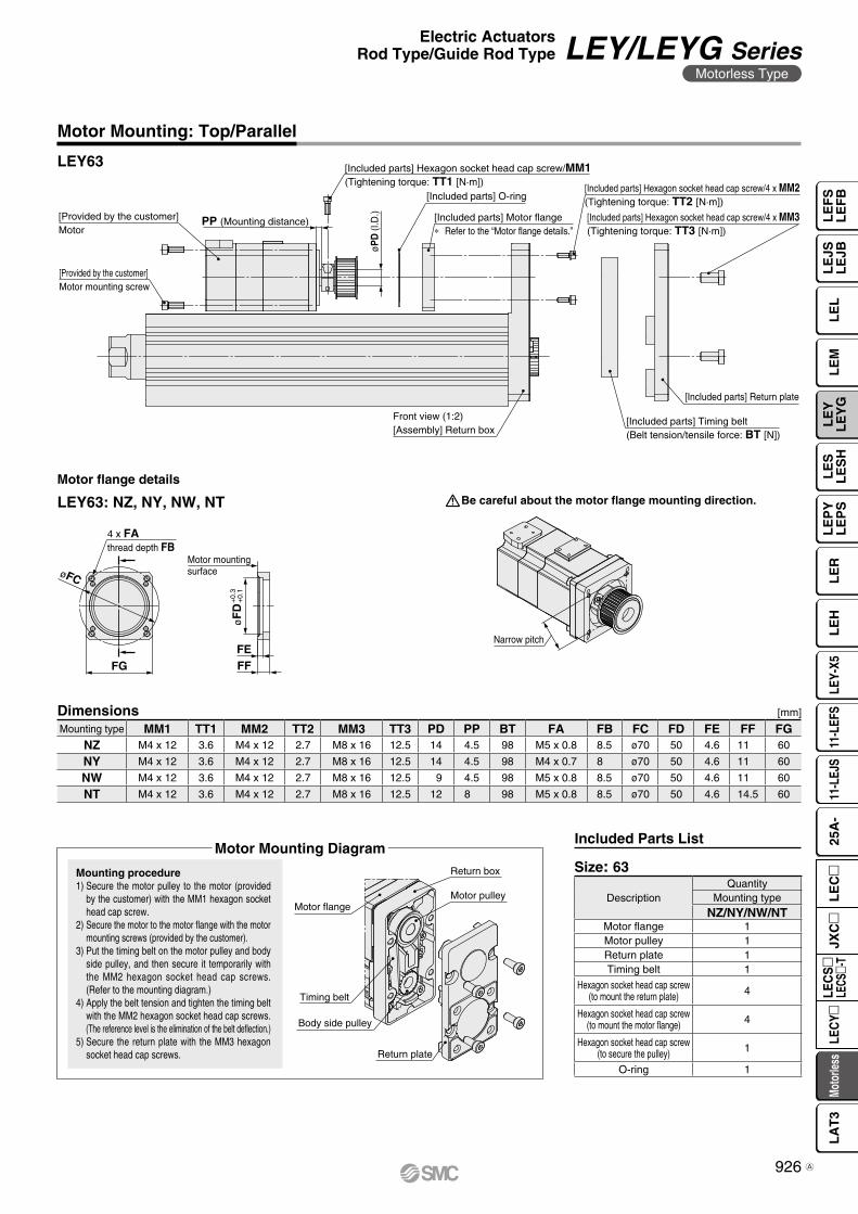
Motor flange
Timing belt
Return box
Motor pulley
Body side pulley
Return plate
[Provided by the customer]Motor
[Provided by the customer]Motor mounting screw
PP (Mounting distance)
øPD
(I.D
.)
[Included parts] Hexagon socket head cap screw/MM1(Tightening torque: TT1 [N·m])
[Included parts] Hexagon socket head cap screw/4 x MM2(Tightening torque: TT2 [N·m])
Front view (1:2)[Assembly] Return box
[Included parts] Timing belt(Belt tension/tensile force: BT [N])
[Included parts] Return plate
[Included parts] Hexagon socket head cap screw/4 x MM3(Tightening torque: TT3 [N·m])
[Included parts] Motor flange∗ Refer to the “Motor flange details.”
[Included parts] O-ring
4 x FAthread depth FB
FG FFFE
øF
D+
0.3
+0.
1
øFC
Motor mountingsurface
Narrow pitch
Motor Mounting: Top/Parallel
LEY63
Mounting type MM1 TT1 MM2 TT2 MM3 TT3 PD PP BT FA FB FC FD FE FF FGNZ M4 x 12 3.6 M4 x 12 2.7 M8 x 16 12.5 14 4.5 98 M5 x 0.8 8.5 ø70 50 4.6 11 60
NY M4 x 12 3.6 M4 x 12 2.7 M8 x 16 12.5 14 4.5 98 M4 x 0.7 8 ø70 50 4.6 11 60
NW M4 x 12 3.6 M4 x 12 2.7 M8 x 16 12.5 9 4.5 98 M5 x 0.8 8.5 ø70 50 4.6 11 60
NT M4 x 12 3.6 M4 x 12 2.7 M8 x 16 12.5 12 8 98 M5 x 0.8 8.5 ø70 50 4.6 14.5 60
DescriptionQuantity
Mounting typeNZ/NY/NW/NT
Motor flange 1Motor pulley 1Return plate 1Timing belt 1
Hexagon socket head cap screw(to mount the return plate) 4
Hexagon socket head cap screw(to mount the motor flange) 4
Hexagon socket head cap screw(to secure the pulley) 1
O-ring 1
Dimensions
Size: 63
[mm]
Mounting procedure1) Secure the motor pulley to the motor (provided
by the customer) with the MM1 hexagon socket head cap screw.
2) Secure the motor to the motor flange with the motor mounting screws (provided by the customer).
3) Put the timing belt on the motor pulley and body side pulley, and then secure it temporarily with the MM2 hexagon socket head cap screws. (Refer to the mounting diagram.)
4) Apply the belt tension and tighten the timing belt with the MM2 hexagon socket head cap screws. (The reference level is the elimination of the belt deflection.)
5) Secure the return plate with the MM3 hexagon socket head cap screws.
Motor flange details
LEY63: NZ, NY, NW, NT
Included Parts ListMotor Mounting Diagram
Be careful about the motor flange mounting direction.
926
Electric ActuatorsRod Type/Guide Rod Type LEY/LEYG Series
Motorless Type
LE
FS
LE
FB
LE
LL
EJS
LE
JBL
EM
LE
YL
EY
GL
ES
LE
SH
LE
PY
LE
PS
LE
RL
EH
LEY-
X511
-LEF
S11
-LEJ
S25
A-
Moto
rless
LEC
Y�LE
CS
�LE
CS�-
TJX
C�
LE
C�
LA
T3
A
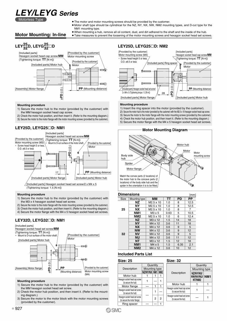
[Provided by the customer]Motor mounting screw (M4)∗ Screw head height 5 or less,
O.D. ø6.5 or less [Included parts] Ring spacer
[Included parts] Hexagon socket head cap screw/MM(Tightening torque: TT [N·m])
[Provided by the customer]Motor
PP (Mounting distance)
[Included parts] Motor hubøP
D (I
.D.)
28
[Included parts] Motor flange
[Included parts] Hexagon socket head set screw/2 x M4 x 5 (Tightening torque: 1.5 [N·m])
[Included parts] Hexagon socket head cap screw/MM(Tightening torque: TT [N·m])
[Included parts] Motor hub[Provided by the customer]Motor
[Provided by the customer]Motor mounting screw
PP (Mounting distance)
øP
D (
I.D.)[Assembly] Motor flange
Motor hub
MotorMotor mounting screwBody side
hub
Spider
Motor flange
Match the convex parts (2 locations) of the motor hub to the concave parts (2 locations) of the body side hub and the spider in the orientation it is to be fitted.
[Assembly] Motor flange
[Included parts] Hexagon socket head set screw/MM(Tightening torque: TT [N·m])∗ Mount to D-cut surface of the motor shaft.
[Included parts] Motor hub
[Provided by the customer]Motor
[Provided by the customer]Motor mounting screw(M4)
PP (Mounting distance)ø
PD
(I.D
.)
17
øP
D (
I.D.)
[Included parts] Motor flange
[Included parts] Hexagon socket head set screw/2 x M4 x 5(Tightening torque: 1.5 [N·m])
[Provided by the customer]Motor mounting screw (M3)∗ Screw head height 5 or less,
O.D. ø6.5 or less
[Included parts] Hexagon socket head set screw/MM(Tightening torque: TT [N·m])∗ Mount to D-cut surface of the motor shaft.
[Included parts] Motor hub
[Provided by the customer] Motor
PP (Mounting distance)
Mounting procedure1) Insert the ring spacer into the motor (provided by the customer).2) Secure the motor hub to the motor (provided by the customer) with the M2.5 x 10 hexagon socket head cap screw.3) Secure the motor to the motor flange with the motor mounting screws (provided by the customer).4) Check the motor hub position, and then insert it. (Refer to the mounting diagram.)5) Secure the motor flange with the M4 x 5 hexagon socket head set screws.
LEY25D, LEYG25lD: NM2
Size: 32
Description
QuantityMounting type
NZ/NY/NX/NW/NV/NU/
NT/NM2NM1
Motor hub 1 1Hexagon socket head cap screw
(to secure the hub) 1 —
Hexagon socket head set screw(to secure the hub) — 1
Size Mounting type MM TT PD PP
25
NZ M2.5 x 10 1.0 8 12.5NY M2.5 x 10 1.0 8 12.5NX M2.5 x 10 1.0 8 7
NM1 M3 x 5 0.63 5 10.5NM2 M2.5 x 10 1.0 6 12.4
32
NZ M3 x 12 1.5 14 18NY M4 x 12 3.6 11 18NX M4 x 12 3.6 9 5NW M4 x 12 3.6 9 12NV M4 x 12 3.6 9 5NU M4 x 12 3.6 11 12NT M3 x 12 1.5 12 18
NM1 M4 x 5 1.5 6.35 2.1NM2 M4 x 12 3.6 10 12
[mm]Dimensions
Motor Mounting: In-line
Mounting procedure1) Secure the motor hub to the motor (provided by the customer) with
the MM hexagon socket head cap screw.2) Check the motor hub position, and then insert it. (Refer to the mounting diagram.)3) Secure the motor to the motor flange with the motor mounting screws (provided by the customer).
LEY25D, LEYG25lD: NM1
Mounting procedure1) Secure the motor hub to the motor (provided by the customer) with
the M3 x 4 hexagon socket head set screw.2) Secure the motor to the motor flange with the motor mounting screws (provided by the customer).3) Check the motor hub position, and then insert it. (Refer to the mounting diagram.)4) Secure the motor flange with the M4 x 5 hexagon socket head set screws.
LEY32D, LEYG32lD: NM1
Mounting procedure1) Secure the motor hub to the motor (provided by the customer) with
the MM hexagon socket head set screw.2) Check the motor hub position, and then insert it. (Refer to the mount-
ing diagram.)3) Secure the motor to the motor block with the motor mounting screws
(provided by the customer).
DescriptionQuantity
Mounting typeNZ/NY/NX NM1 NM2
Motor hub 1 1 1Hexagon socket head cap screw
(to secure the hub) 1 — 1
Motor flange — 1 1Hexagon socket head set screw
(to secure the hub)—
1 —
Hexagon socket head set screw(to secure the motor flange) 2 2
Ring spacer — — 1
Size: 25
Included Parts List
¡The motor and motor mounting screws should be provided by the customer.¡Motor shaft type should be cylindrical for the NZ, NY, NX, NW, NM2 mounting types, and D-cut type for the
NM1 mounting type.¡When mounting a hub, remove all oil content, dust, and dirt adhered to the shaft and the inside of the hub.¡Take measures to prevent the loosening of the motor mounting screws and hexagon socket head set screws.
LEY D, LEYG lD2532
2532
Motor Mounting Diagram
927
LEY/LEYG SeriesMotorless Type
A
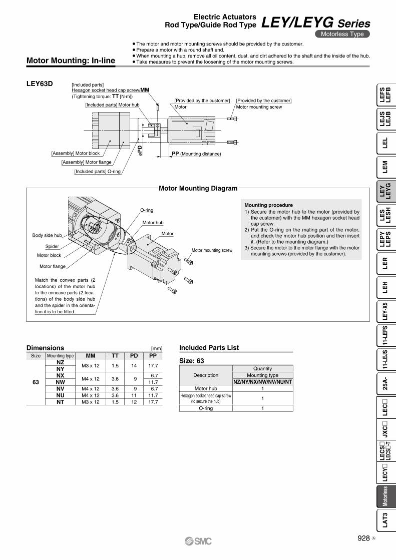
[Included parts] O-ring
[Assembly] Motor flange
[Included parts] Motor hub
[Included parts] Hexagon socket head cap screw/MM(Tightening torque: TT [N·m])
[Provided by the customer]Motor mounting screw
[Provided by the customer]Motor
PP (Mounting distance)øP
D
[Assembly] Motor block
Motor mounting screw
Motor
Motor hub
O-ring
Body side hub
Spider
Motor block
Motor flange
Match the convex parts (2 locations) of the motor hub to the concave parts (2 loca-tions) of the body side hub and the spider in the orienta-tion it is to be fitted.
DescriptionQuantity
Mounting typeNZ/NY/NX/NW/NV/NU/NT
Motor hub 1Hexagon socket head cap screw
(to secure the hub) 1
O-ring 1
Size Mounting type MM TT PD PP
63
NZM3 x 12 1.5 14 17.7
NYNX
M4 x 12 3.6 96.7
NW 11.7NV M4 x 12 3.6 9 6.7NU M4 x 12 3.6 11 11.7NT M3 x 12 1.5 12 17.7
Motor Mounting: In-line
LEY63D
Dimensions [mm]
Mounting procedure1) Secure the motor hub to the motor (provided by
the customer) with the MM hexagon socket head cap screw.
2) Put the O-ring on the mating part of the motor, and check the motor hub position and then insert it. (Refer to the mounting diagram.)
3) Secure the motor to the motor flange with the motor mounting screws (provided by the customer).
Size: 63
Included Parts List
Motor Mounting Diagram
¡The motor and motor mounting screws should be provided by the customer.¡Prepare a motor with a round shaft end.¡When mounting a hub, remove all oil content, dust, and dirt adhered to the shaft and the inside of the hub.¡Take measures to prevent the loosening of the motor mounting screws.
928
Electric ActuatorsRod Type/Guide Rod Type LEY/LEYG Series
Motorless Type
LE
FS
LE
FB
LE
LL
EJS
LE
JBL
EM
LE
YL
EY
GL
ES
LE
SH
LE
PY
LE
PS
LE
RL
EH
LEY-
X511
-LEF
S11
-LEJ
S25
A-
Moto
rless
LEC
Y�LE
CS
�LE
CS�-
TJX
C�
LE
C�
LA
T3
A
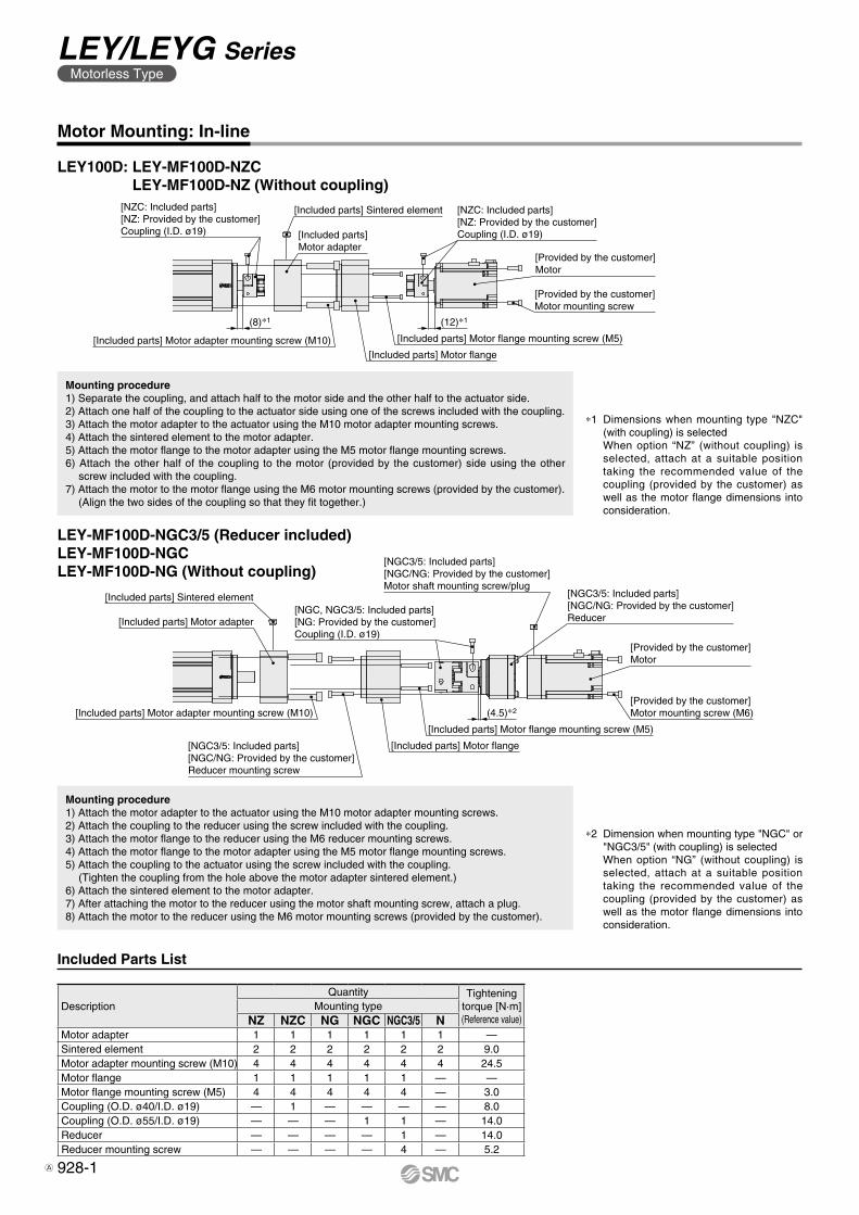
[NZC: Included parts][NZ: Provided by the customer]Coupling (I.D. ø19)
[NZC: Included parts][NZ: Provided by the customer]Coupling (I.D. ø19)
[Provided by the customer]Motor
[Provided by the customer]Motor mounting screw
[Included parts] Motor flange mounting screw (M5)
[Included parts] Motor flange
(8)∗1 (12)∗1
[Included parts] Motor adapter mounting screw (M10)
[Included parts] Sintered element
[Included parts] Sintered element
[Included parts] Motor adapter
[Included parts] Motor adapter mounting screw (M10)
[NGC3/5: Included parts][NGC/NG: Provided by the customer]Reducer mounting screw
[Included parts] Motor flange
[Included parts] Motor flange mounting screw (M5)
[Provided by the customer]Motor mounting screw (M6)
[Provided by the customer]Motor
[NGC3/5: Included parts][NGC/NG: Provided by the customer]Reducer
[NGC3/5: Included parts][NGC/NG: Provided by the customer]Motor shaft mounting screw/plug
[NGC, NGC3/5: Included parts][NG: Provided by the customer]Coupling (I.D. ø19)
(4.5)∗2
[Included parts]Motor adapter
Motor Mounting: In-line
Mounting procedure1) Separate the coupling, and attach half to the motor side and the other half to the actuator side.2) Attach one half of the coupling to the actuator side using one of the screws included with the coupling.3) Attach the motor adapter to the actuator using the M10 motor adapter mounting screws.4) Attach the sintered element to the motor adapter.5) Attach the motor flange to the motor adapter using the M5 motor flange mounting screws.6) Attach the other half of the coupling to the motor (provided by the customer) side using the other
screw included with the coupling.7) Attach the motor to the motor flange using the M6 motor mounting screws (provided by the customer).
(Align the two sides of the coupling so that they fit together.)
Mounting procedure1) Attach the motor adapter to the actuator using the M10 motor adapter mounting screws.2) Attach the coupling to the reducer using the screw included with the coupling.3) Attach the motor flange to the reducer using the M6 reducer mounting screws.4) Attach the motor flange to the motor adapter using the M5 motor flange mounting screws.5) Attach the coupling to the actuator using the screw included with the coupling.
(Tighten the coupling from the hole above the motor adapter sintered element.)6) Attach the sintered element to the motor adapter.7) After attaching the motor to the reducer using the motor shaft mounting screw, attach a plug.8) Attach the motor to the reducer using the M6 motor mounting screws (provided by the customer).
LEY100D: LEY-MF100D-NZC LEY-MF100D-NZ (Without coupling)
LEY-MF100D-NGC3/5 (Reducer included)LEY-MF100D-NGCLEY-MF100D-NG (Without coupling)
Included Parts List
DescriptionQuantity Tightening
torque [N·m](Reference value)
Mounting typeNZ NZC NG NGC NGC3/5 N
Motor adapter 1 1 1 1 1 1 —Sintered element 2 2 2 2 2 2 9.0Motor adapter mounting screw (M10) 4 4 4 4 4 4 24.5Motor flange 1 1 1 1 1 — —Motor flange mounting screw (M5) 4 4 4 4 4 — 3.0Coupling (O.D. ø40/I.D. ø19) — 1 — — — — 8.0Coupling (O.D. ø55/I.D. ø19) — — — 1 1 — 14.0Reducer — — — — 1 — 14.0Reducer mounting screw — — — — 4 — 5.2
*1 Dimensions when mounting type "NZC" (with coupling) is selectedWhen option “NZ” (without coupling) is selected, attach at a suitable position taking the recommended value of the coupling (provided by the customer) as well as the motor flange dimensions into consideration.
*2 Dimension when mounting type "NGC" or "NGC3/5" (with coupling) is selectedWhen option “NG” (without coupling) is selected, attach at a suitable position taking the recommended value of the coupling (provided by the customer) as well as the motor flange dimensions into consideration.
928-1
LEY/LEYG SeriesMotorless Type
A

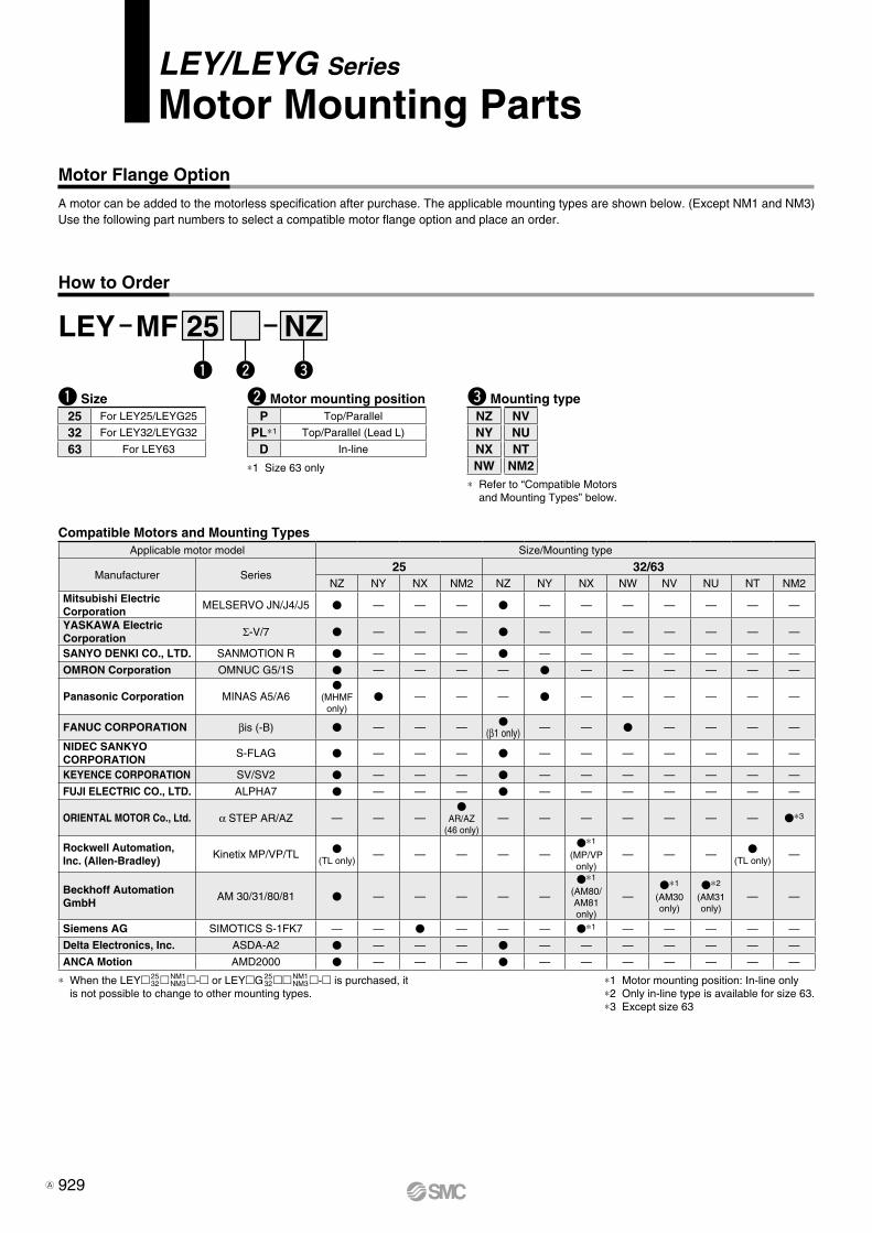
LEY/LEYG Series
Motor Mounting Parts
Motor Flange Option
A motor can be added to the motorless specification after purchase. The applicable mounting types are shown below. (Except NM1 and NM3) Use the following part numbers to select a compatible motor flange option and place an order.
How to Order
q Size
LEY MF NZ25
w Motor mounting position
q w e
25 For LEY25/LEYG25
32 For LEY32/LEYG32
63 For LEY63
P Top/Parallel
PL*1 Top/Parallel (Lead L)
D In-line
*1 Size 63 only
* Refer to “Compatible Motors and Mounting Types” below.
e Mounting type
* When the LEY25 32NM1
NM3- or LEYG25 32NM1
NM3- is purchased, it is not possible to change to other mounting types.
*1 Motor mounting position: In-line only*2 Only in-line type is available for size 63.*3 Except size 63
NZNYNXNW
NVNUNT
NM2
Compatible Motors and Mounting TypesApplicable motor model Size/Mounting type
Manufacturer Series25 32/63
NZ NY NX NM2 NZ NY NX NW NV NU NT NM2Mitsubishi ElectricCorporation
MELSERVO JN/J4/J5 V — — — V — — — — — — —
YASKAWA Electric Corporation Σ-V/7 V — — — V — — — — — — —
SANYO DENKI CO., LTD. SANMOTION R V — — — V — — — — — — —
OMRON Corporation OMNUC G5/1S V — — — — V — — — — — —
Panasonic Corporation MINAS A5/A6V
(MHMF only)
V — — — V — — — — — —
FANUC CORPORATION βis (-B) V — — — V(β1 only) — — V — — — —
NIDEC SANKYO CORPORATION
S-FLAG V — — — V — — — — — — —
KEYENCE CORPORATION SV/SV2 V — — — V — — — — — — —
FUJI ELECTRIC CO., LTD. ALPHA7 V — — — V — — — — — — —
ORIENTAL MOTOR Co., Ltd. α STEP AR/AZ — — —V
AR/AZ(46 only)
— — — — — — — V*3
Rockwell Automation, Inc. (Allen-Bradley)
Kinetix MP/VP/TL V(TL only)
— — — — —V*1
(MP/VP only)
— — — V(TL only)
—
Beckhoff AutomationGmbH
AM 30/31/80/81 V — — — — —
V*1
(AM80/AM81 only)
—V*1
(AM30 only)
V*2
(AM31 only)
— —
Siemens AG SIMOTICS S-1FK7 — — V — — — V*1 — — — — —
Delta Electronics, Inc. ASDA-A2 V — — — V — — — — — — —
ANCA Motion AMD2000 V — — — V — — — — — — —
929A
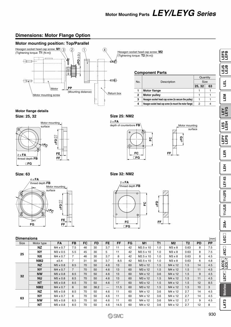
2 x FAdepth of counterbore FB Motor mounting
surface
øF
D
FC
FFFC�FG
øF
D
FF�FGFC
FC
2 x FAthread depth FB
Motor mounting screw
Motor
Hexagon socket head cap screw: M1(Tightening torque: T1 [N·m])
Return box
PP (Mounting distance)
øP
D (
I.D.)
qwe r Hexagon socket head cap screw: M2(Tightening torque: T2 [N·m])
2 x FAthread depth FB
øFC øF
D
FFFE
�FG
Motor mountingsurface
+0.
3+
0.1
øF
D+
0.3
+0.
1
4 x FAthread depth FB
Motor mountingsurface
FEFG FF
øFC
Size 25: NM2
Size 32: NM2
Dimensions: Motor Flange Option
Motor mounting position: Top/Parallel
Dimensions [mm]
Motor flange details
Size: 25, 32
Size: 63
Component Parts
No. Description
Quantity
Size
25, 32 631 Motor flange 1 1
2 Motor pulley 1 1
3 Hexagon socket head cap screw (to secure the pulley) 1 1
4 Hexagon socket head cap screw (to mount the motor flange) 2 4
Size Motor type FA FB FC FD FE FF FG M1 T1 M2 T2 PD PP
25
NZ M4 x 0.7 7.5 46 30 3.7 11 42 M2.5 x 10 1.0 M3 x 8 0.63 8 7.5
NY M3 x 0.5 5.5 45 30 5 11 42 M2.5 x 10 1.0 M3 x 8 0.63 8 7.5
NX M4 x 0.7 7 46 30 3.7 8 42 M2.5 x 10 1.0 M3 x 8 0.63 8 4.5
NM2 ø3.4 7 31 30 3.7 8.5 42 M2.5 x 10 1.0 M3 x 8 0.63 6 4.8
32
NZ M5 x 0.8 8.5 70 50 4.6 13 60 M3 x 12 1.5 M4 x 12 1.5 14 4.5
NY M4 x 0.7 7 70 50 4.6 13 60 M3 x 12 1.5 M4 x 12 1.5 11 4.5
NW M5 x 0.8 8.5 70 50 4.6 13 60 M4 x 12 3.6 M4 x 12 1.5 9 4.5
NU M5 x 0.8 8.5 70 50 4.6 13 60 M3 x 12 1.5 M4 x 12 1.5 11 4.5
NT M5 x 0.8 8.5 70 50 4.6 17 60 M3 x 12 1.5 M4 x 12 1.5 12 8.5
NM2 M4 x 0.7 8 50 38.2 — 11.5 60 M3 x 12 1.5 M4 x 12 1.5 10 3
63
NZ M5 x 0.8 8.5 70 50 4.6 11 60 M4 x 12 3.6 M4 x 12 2.7 14 4.5
NY M4 x 0.7 8 70 50 4.6 11 60 M4 x 12 3.6 M4 x 12 2.7 14 4.5
NW M5 x 0.8 8.5 70 50 4.6 11 60 M4 x 12 3.6 M4 x 12 2.7 9 4.5
NT M5 x 0.8 8.5 70 50 4.6 14.5 60 M4 x 12 3.6 M4 x 12 2.7 12 8
930
Motor Mounting Parts LEY/LEYG Series
LE
FS
LE
FB
LE
LL
EJS
LE
JBL
EM
LE
YL
EY
GL
ES
LE
SH
LE
PY
LE
PS
LE
RL
EH
LEY-
X511
-LEF
S11
-LEJ
S25
A-
Moto
rless
LEC
Y�LE
CS
�LE
CS�-
TJX
C�
LE
C�
LA
T3
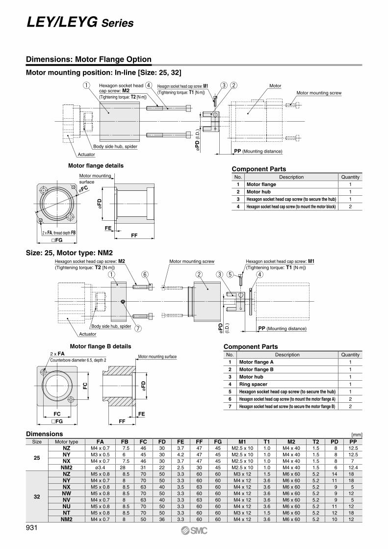
�FGFC
FC
2 x FACounterbore diameter 6.5, depth 2
Motor mounting surface
øF
D
FEFF
y w re tq
u
Hexagon socket head cap screw: M2(Tightening torque: T2 [N·m])
Motor mounting screw Hexagon socket head cap screw: M1(Tightening torque: T1 [N·m])
PP (Mounting distance)Actuator
Body side hub, spider
øP
D(I
.D.)
Hexagon socket head cap screw: M2(Tightening torque: T2 [N·m])
q r Hexagon socket head cap screw: M1(Tightening torque: T1 [N·m])
e w
øP
D (
I.D.)
PP (Mounting distance)Body side hub, spider
Actuator
Motor
Motor mounting screw
2 x FA, thread depth FB�FG
øFC
FF
øF
D
Motor mountingsurface
FE
Size: 25, Motor type: NM2
Motor flange B details Component PartsNo. Description Quantity
1 Motor flange A 1
2 Motor flange B 1
3 Motor hub 1
4 Ring spacer 1
5 Hexagon socket head cap screw (to secure the hub) 1
6 Hexagon socket head cap screw (to mount the motor flange A) 2
7 Hexagon socket head set screw (to secure the motor flange B) 2
Dimensions: Motor Flange Option
Motor mounting position: In-line [Size: 25, 32]
Motor flange details Component PartsNo. Description Quantity
1 Motor flange 1
2 Motor hub 1
3 Hexagon socket head cap screw (to secure the hub) 1
4 Hexagon socket head cap screw (to mount the motor block) 2
Dimensions [mm]Size Motor type FA FB FC FD FE FF FG M1 T1 M2 T2 PD PP
25
NZ M4 x 0.7 7.5 46 30 3.7 47 45 M2.5 x 10 1.0 M4 x 40 1.5 8 12.5NY M3 x 0.5 6 45 30 4.2 47 45 M2.5 x 10 1.0 M4 x 40 1.5 8 12.5NX M4 x 0.7 7.5 46 30 3.7 47 45 M2.5 x 10 1.0 M4 x 40 1.5 8 7
NM2 ø3.4 28 31 22 2.5 30 45 M2.5 x 10 1.0 M4 x 40 1.5 6 12.4
32
NZ M5 x 0.8 8.5 70 50 3.3 60 60 M3 x 12 1.5 M6 x 60 5.2 14 18NY M4 x 0.7 8 70 50 3.3 60 60 M4 x 12 3.6 M6 x 60 5.2 11 18NX M5 x 0.8 8.5 63 40 3.5 63 60 M4 x 12 3.6 M6 x 60 5.2 9 5NW M5 x 0.8 8.5 70 50 3.3 60 60 M4 x 12 3.6 M6 x 60 5.2 9 12NV M4 x 0.7 8 63 40 3.3 63 60 M4 x 12 3.6 M6 x 60 5.2 9 5NU M5 x 0.8 8.5 70 50 3.3 60 60 M4 x 12 3.6 M6 x 60 5.2 11 12NT M5 x 0.8 8.5 70 50 3.3 60 60 M3 x 12 1.5 M6 x 60 5.2 12 18
NM2 M4 x 0.7 8 50 36 3.3 60 60 M4 x 12 3.6 M6 x 60 5.2 10 12
931
LEY/LEYG Series
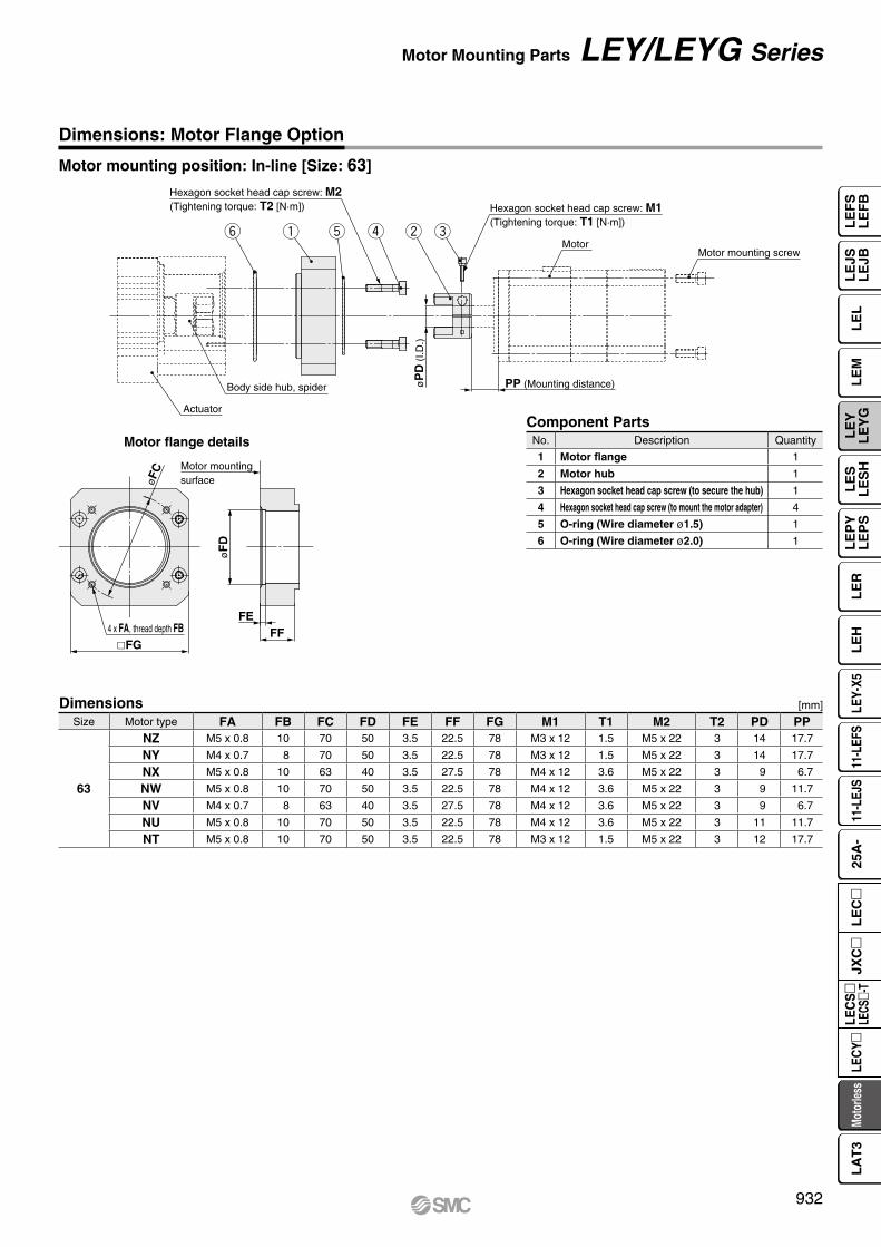
Hexagon socket head cap screw: M2(Tightening torque: T2 [N·m]) Hexagon socket head cap screw: M1
(Tightening torque: T1 [N·m])q w erty
Motor
Actuator
Body side hub, spider øP
D (
I.D.)
PP (Mounting distance)
Motor mounting screw
FE4 x FA, thread depth FB
�FG
øF
D
FF
øFC Motor mounting
surface
Dimensions: Motor Flange Option
Motor mounting position: In-line [Size: 63]
Motor flange detailsComponent PartsNo. Description Quantity
1 Motor flange 1
2 Motor hub 1
3 Hexagon socket head cap screw (to secure the hub) 1
4 Hexagon socket head cap screw (to mount the motor adapter) 4
5 O-ring (Wire diameter ø1.5) 1
6 O-ring (Wire diameter ø2.0) 1
Dimensions [mm]
Size Motor type FA FB FC FD FE FF FG M1 T1 M2 T2 PD PP
63
NZ M5 x 0.8 10 70 50 3.5 22.5 78 M3 x 12 1.5 M5 x 22 3 14 17.7
NY M4 x 0.7 8 70 50 3.5 22.5 78 M3 x 12 1.5 M5 x 22 3 14 17.7
NX M5 x 0.8 10 63 40 3.5 27.5 78 M4 x 12 3.6 M5 x 22 3 9 6.7
NW M5 x 0.8 10 70 50 3.5 22.5 78 M4 x 12 3.6 M5 x 22 3 9 11.7
NV M4 x 0.7 8 63 40 3.5 27.5 78 M4 x 12 3.6 M5 x 22 3 9 6.7
NU M5 x 0.8 10 70 50 3.5 22.5 78 M4 x 12 3.6 M5 x 22 3 11 11.7
NT M5 x 0.8 10 70 50 3.5 22.5 78 M3 x 12 1.5 M5 x 22 3 12 17.7
932
Motor Mounting Parts LEY/LEYG Series
LE
FS
LE
FB
LE
LL
EJS
LE
JBL
EM
LE
YL
EY
GL
ES
LE
SH
LE
PY
LE
PS
LE
RL
EH
LEY-
X511
-LEF
S11
-LEJ
S25
A-
Moto
rless
LEC
Y�LE
CS
�LE
CS�-
TJX
C�
LE
C�
LA
T3
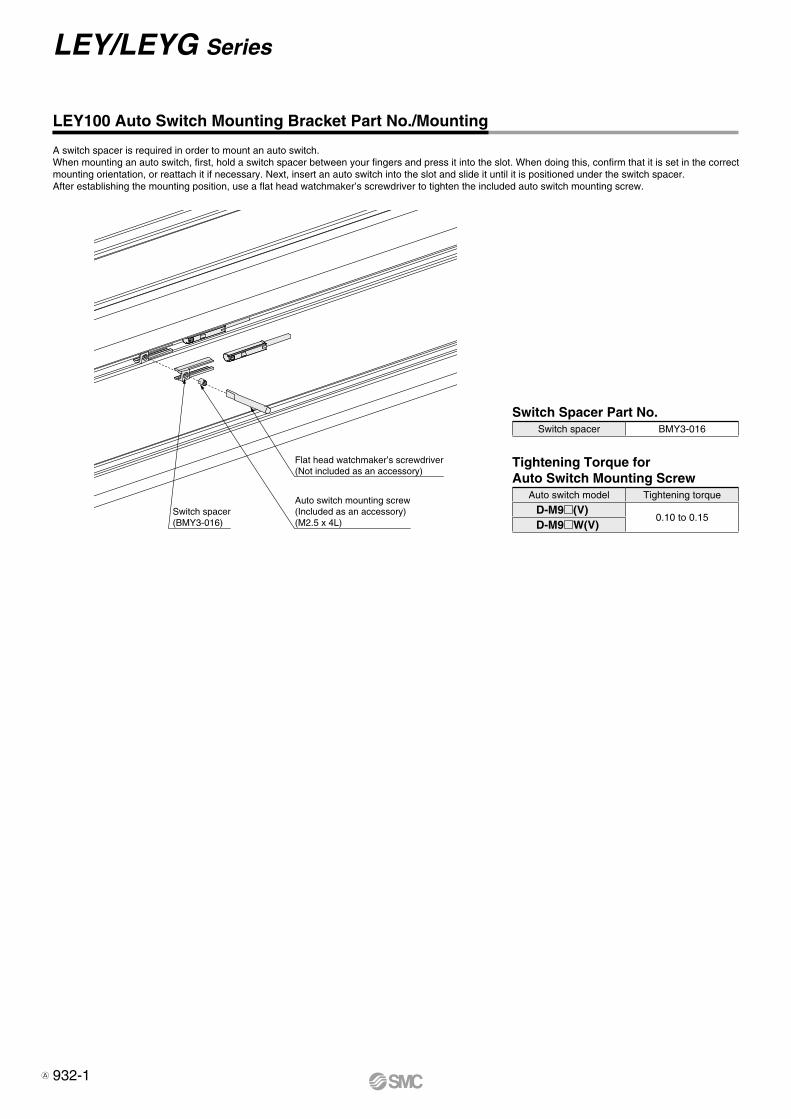
Flat head watchmaker’s screwdriver(Not included as an accessory)
Auto switch mounting screw(Included as an accessory)(M2.5 x 4L)
Switch spacer(BMY3-016)
LEY100 Auto Switch Mounting Bracket Part No./Mounting
A switch spacer is required in order to mount an auto switch.When mounting an auto switch, first, hold a switch spacer between your fingers and press it into the slot. When doing this, confirm that it is set in the correct mounting orientation, or reattach it if necessary. Next, insert an auto switch into the slot and slide it until it is positioned under the switch spacer.After establishing the mounting position, use a flat head watchmaker’s screwdriver to tighten the included auto switch mounting screw.
Switch Spacer Part No.Switch spacer BMY3-016
Tightening Torque for Auto Switch Mounting Screw
Auto switch model Tightening torque
D-M9m(V)0.10 to 0.15
D-M9mW(V)
932-1
LEY/LEYG Series
A


PrecautionsCaution
Fix the auto switch with the existing screw installed on the auto switch body. The auto switch may be damaged if a screw other than the one supplied is used.
Weight [g]
Grommet
∗ Refer to page 996 for solid state auto switch common specifications.∗ Refer to page 996 for lead wire lengths.
DimensionsD-M9m D-M9mV
P 2-wire load current is reduced (2.5 to 40 mA).
P Using flexible cable as standard spec.
[mm]
Oilproof Heavy-duty Lead Wire Specifications
Solid State Auto SwitchDirect Mounting TypeD-M9N(V)/D-M9P(V)/D-M9B(V)
Auto Switch SpecificationsPLC: Programmable Logic Controller
Refer to the SMC website for details on products that are compliant with international standards.
RoHS
Most sensitive position
ø2.
6
2.6
3.95
2.8
6
22.8
Mounting screw M2.5 x 4 L
Slotted set screw (flat point)
Indicator light
19.5
15.9
7.5
9.5
4
2.6
0.3
ø2.6
Indicator light
Slotted set screw2
Most sensitive position6
2.8 4.6
500
(100
0) (
3000
) (5
000)
Mounting screw M2.5 x 4 L
D-M9l, D-M9lV (With indicator light)Auto switch model D-M9N D-M9NV D-M9P D-M9PV D-M9B D-M9BVElectrical entry direction In-line Perpendicular In-line Perpendicular In-line Perpendicular
Wiring type 3-wire 2-wire
Output type NPN PNP —
Applicable load IC circuit, Relay, PLC 24 VDC relay, PLC
Power supply voltage 5, 12, 24 VDC (4.5 to 28 V) —
Current consumption 10 mA or less —
Load voltage 28 VDC or less — 24 VDC (10 to 28 VDC)
Load current 40 mA or less 2.5 to 40 mA
Internal voltage drop 0.8 V or less at 10 mA (2 V or less at 40 mA) 4 V or less
Leakage current 100 mA or less at 24 VDC 0.8 mA or less
Indicator light Red LED illuminates when turned ON.
Standard CE marking, RoHS
Auto switch model D-M9N(V) D-M9P(V) D-M9B(V)Sheath Outside diameter [mm] 2.6
InsulatorNumber of cores 3 cores (Brown/Blue/Black) 2 cores (Brown/Blue)
Outside diameter [mm] 0.88
ConductorEffective area [mm2] 0.15
Strand diameter [mm] 0.05
Minimum bending radius [mm] (Reference values) 17
Auto switch model D-M9N(V) D-M9P(V) D-M9B(V)
Lead wire length
0.5 m (Nil) 8 7
1 m (M) 14 13
3 m (L) 41 38
5 m (Z) 68 63
933
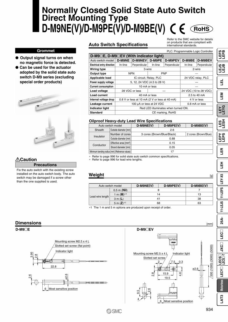
PrecautionsCaution
Fix the auto switch with the existing screw installed on the auto switch body. The auto switch may be damaged if a screw other than the one supplied is used.
Weight [g]
∗ Refer to page 996 for solid state auto switch common specifications.∗ Refer to page 996 for lead wire lengths.
DimensionsD-M9mE D-M9mEV
[mm]
Oilproof Heavy-duty Lead Wire Specifications
Normally Closed Solid State Auto SwitchDirect Mounting TypeD-M9NE(V)/D-M9PE(V)/D-M9BE(V)
Auto Switch SpecificationsPLC: Programmable Logic Controller
Refer to the SMC website for details on products that are compliant with international standards.
∗1 The 1 m and 5 m options are produced upon receipt of order.
Grommet
P Output signal turns on when no magnetic force is detected.
P Can be used for the actuator adopted by the solid state auto switch D-M9 series (excluding special order products)
RoHS
Most sensitive position
ø2.
6
2.6
3.95
2.8
6
22.8
Mounting screw M2.5 x 4 L
Slotted set screw (flat point)
Indicator light
19.5
15.9
7.5
9.5
4
2.6
0.3
ø2.6
Indicator light
Slotted set screw2
Most sensitive position6
2.8
4.6
500
(100
0) (
3000
) (5
000)
Mounting screw M2.5 x 4 L
D-M9lE, D-M9lEV (With indicator light)Auto switch model D-M9NE D-M9NEV D-M9PE D-M9PEV D-M9BE D-M9BEVElectrical entry direction In-line Perpendicular In-line Perpendicular In-line Perpendicular
Wiring type 3-wire 2-wire
Output type NPN PNP —
Applicable load IC circuit, Relay, PLC 24 VDC relay, PLC
Power supply voltage 5, 12, 24 VDC (4.5 to 28 V) —
Current consumption 10 mA or less —
Load voltage 28 VDC or less — 24 VDC (10 to 28 VDC)
Load current 40 mA or less 2.5 to 40 mA
Internal voltage drop 0.8 V or less at 10 mA (2 V or less at 40 mA) 4 V or less
Leakage current 100 mA or less at 24 VDC 0.8 mA or less
Indicator light Red LED illuminates when turned ON.
Standard CE marking, RoHS
Auto switch model D-M9NE(V) D-M9PE(V) D-M9BE(V)Sheath Outside diameter [mm] 2.6
InsulatorNumber of cores 3 cores (Brown/Blue/Black) 2 cores (Brown/Blue)
Outside diameter [mm] 0.88
ConductorEffective area [mm2] 0.15
Strand diameter [mm] 0.05
Minimum bending radius [mm] (Reference values) 17
Auto switch model D-M9NE(V) D-M9PE(V) D-M9BE(V)
Lead wire length
0.5 m (Nil) 8 7
1 m (M)∗1 14 13
3 m (L) 41 38
5 m (Z)∗1 68 63
934
LE
FS
LE
FB
LE
LL
EJS
LE
JBL
EM
LE
YL
EY
GL
ES
LE
SH
LE
PY
LE
PS
LE
RL
EH
LEY-
X511
-LEF
S11
-LEJ
S25
A-
Moto
rless
LEC
Y�LE
CS
�LE
CS�-
TJX
C�
LE
C�
LA
T3

Weight [g]
[mm]Dimensions
Grommet
∗ Refer to page 996 for solid state auto switch common specifications.∗ Refer to page 996 for lead wire lengths.
P 2-wire load current is reduced (2.5 to 40 mA).
P Using flexible cable as standard spec.
P The proper operating range can be determined by the color of the light. (Red → Green ← Red)
D-M9mW D-M9mWV
Oilproof Flexible Heavy-duty Lead Wire Specifications
2-Color Indicator Solid State Auto SwitchDirect Mounting TypeD-M9NW(V)/D-M9PW(V)/D-M9BW(V)
PrecautionsCaution
Fix the auto switch with the existing screw installed on the auto switch body. The auto switch may be damaged if a screw other than the one supplied is used.
Auto Switch SpecificationsRefer to the SMC website for details on products that are compliant with international standards.
PLC: Programmable Logic Controller
RoHS
6 Most sensitive position
2.6
ø2.
6
22.8
Indicator light
3.95
2.8
Slotted set screw (flat point)
Mounting screw M2.5 x 4 L
500
(100
0) (
3000
) (5
000)
Indicator light
ø2.6
4.6
0.37.5
Mounting screw M2.5 x 4 L
Slotted set screw
2.8
9.5 2.
6
4Most sensitive position6
19.5
15.9
2
D-M9lW, D-M9lWV (With indicator light)Auto switch model D-M9NW D-M9NWV D-M9PW D-M9PWV D-M9BW D-M9BWVElectrical entry direction In-line Perpendicular In-line Perpendicular In-line Perpendicular
Wiring type 3-wire 2-wire
Output type NPN PNP —
Applicable load IC circuit, Relay, PLC 24 VDC relay, PLC
Power supply voltage 5, 12, 24 VDC (4.5 to 28 V) —
Current consumption 10 mA or less —
Load voltage 28 VDC or less — 24 VDC (10 to 28 VDC)
Load current 40 mA or less 2.5 to 40 mA
Internal voltage drop 0.8 V or less at 10 mA (2 V or less at 40 mA) 4 V or less
Leakage current 100 mA or less at 24 VDC 0.8 mA or less
Indicator lightOperating range .......... Red LED illuminates.Proper operating range .......... Green LED illuminates.
Standard CE marking, RoHS
Auto switch model D-M9NW(V) D-M9PW(V) D-M9BW(V)Sheath Outside diameter [mm] 2.6
InsulatorNumber of cores 3 cores (Brown/Blue/Black) 2 cores (Brown/Blue)
Outside diameter [mm] 0.88
ConductorEffective area [mm2] 0.15
Strand diameter [mm] 0.05
Minimum bending radius [mm] (Reference values) 17
Auto switch model D-M9NW(V) D-M9PW(V) D-M9BW(V)
Lead wire length
0.5 m (Nil) 8 7
1 m (M) 14 13
3 m (L) 41 38
5 m (Z) 68 63
935
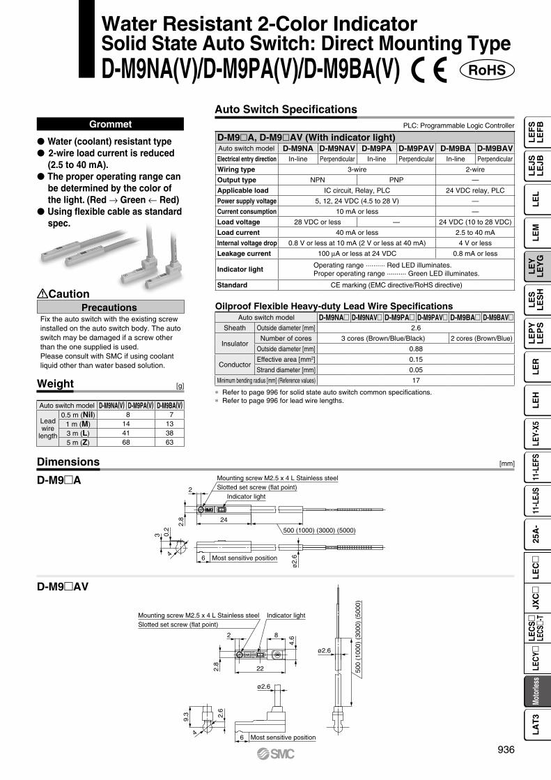
Indicator lightSlotted set screw (flat point)Mounting screw M2.5 x 4 L Stainless steel
2
2.8
0.2
3
24
500 (1000) (3000) (5000)
ø2.
66 Most sensitive position4
4
Indicator lightSlotted set screw (flat point)Mounting screw M2.5 x 4 L Stainless steel
2
2.8
22
8
4.6
ø2.6
9.3 2.
6
6 Most sensitive position
ø2.6
500
(100
0) (
3000
) (5
000)
SMC
∗ Refer to page 996 for solid state auto switch common specifications.∗ Refer to page 996 for lead wire lengths.
Grommet
P Water (coolant) resistant typeP 2-wire load current is reduced
(2.5 to 40 mA).P The proper operating range can
be determined by the color of the light. (Red → Green ← Red)
P Using flexible cable as standard spec.
Oilproof Flexible Heavy-duty Lead Wire Specifications
Water Resistant 2-Color IndicatorSolid State Auto Switch: Direct Mounting TypeD-M9NA(V)/D-M9PA(V)/D-M9BA(V)
PrecautionsCaution
Fix the auto switch with the existing screw installed on the auto switch body. The auto switch may be damaged if a screw other than the one supplied is used.Please consult with SMC if using coolantliquid other than water based solution.
Auto Switch SpecificationsPLC: Programmable Logic Controller
Weight [g]
Dimensions
D-M9A
D-M9AV
[mm]
RoHS
Auto switch model D-M9NA(V) D-M9PA(V) D-M9BA(V)
Leadwire
length
0.5 m (Nil) 8 71 m (M) 14 133 m (L) 41 385 m (Z) 68 63
D-M9lA, D-M9lAV (With indicator light)Auto switch model D-M9NA D-M9NAV D-M9PA D-M9PAV D-M9BA D-M9BAVElectrical entry direction In-line Perpendicular In-line Perpendicular In-line Perpendicular
Wiring type 3-wire 2-wire
Output type NPN PNP —
Applicable load IC circuit, Relay, PLC 24 VDC relay, PLC
Power supply voltage 5, 12, 24 VDC (4.5 to 28 V) —
Current consumption 10 mA or less —
Load voltage 28 VDC or less — 24 VDC (10 to 28 VDC)
Load current 40 mA or less 2.5 to 40 mA
Internal voltage drop 0.8 V or less at 10 mA (2 V or less at 40 mA) 4 V or less
Leakage current 100 mA or less at 24 VDC 0.8 mA or less
Indicator lightOperating range .......... Red LED illuminates.Proper operating range .......... Green LED illuminates.
Standard CE marking (EMC directive/RoHS directive)
Auto switch model D-M9NA D-M9NAV D-M9PA D-M9PAV D-M9BA D-M9BAVSheath Outside diameter [mm] 2.6
InsulatorNumber of cores 3 cores (Brown/Blue/Black) 2 cores (Brown/Blue)
Outside diameter [mm] 0.88
ConductorEffective area [mm2] 0.15
Strand diameter [mm] 0.05
Minimum bending radius [mm] (Reference values) 17
936
LE
FS
LE
FB
LE
LL
EJS
LE
JBL
EM
LE
YL
EY
GL
ES
LE
SH
LE
PY
LE
PS
LE
RL
EH
LEY-
X511
-LEF
S11
-LEJ
S25
A-
Moto
rless
LEC
Y�LE
CS
�LE
CS�-
TJX
C�
LE
C�
LA
T3
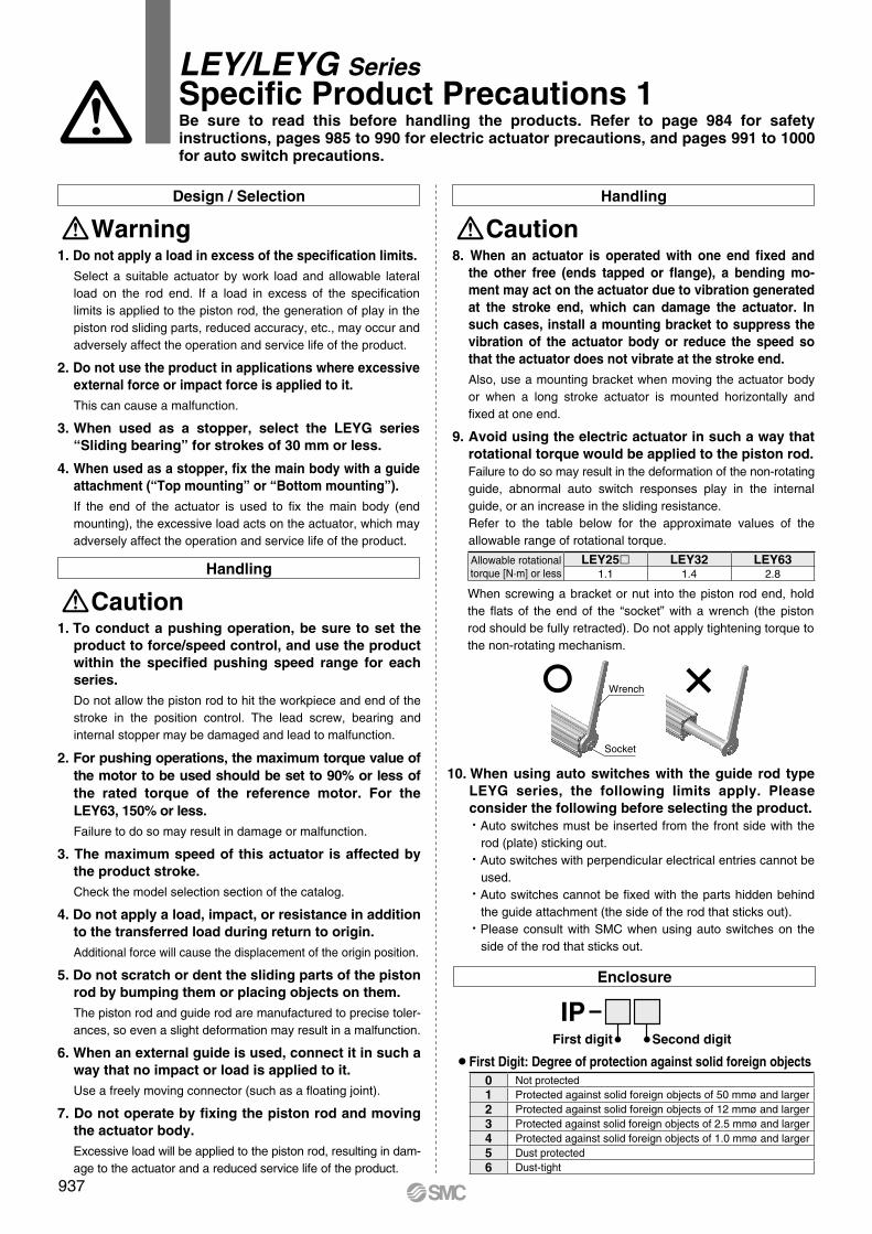
Wrench
Socket
Design / Selection
Warning1. Do not apply a load in excess of the specification limits.
Select a suitable actuator by work load and allowable lateral load on the rod end. If a load in excess of the specification limits is applied to the piston rod, the generation of play in the piston rod sliding parts, reduced accuracy, etc., may occur and adversely affect the operation and service life of the product.
2. Do not use the product in applications where excessive external force or impact force is applied to it.This can cause a malfunction.
3. When used as a stopper, select the LEYG series “Sliding bearing” for strokes of 30 mm or less.
4. When used as a stopper, fix the main body with a guide attachment (“Top mounting” or “Bottom mounting”).If the end of the actuator is used to fix the main body (end mounting), the excessive load acts on the actuator, which may adversely affect the operation and service life of the product.
Handling
Caution1. To conduct a pushing operation, be sure to set the
product to force/speed control, and use the product within the specified pushing speed range for each series.Do not allow the piston rod to hit the workpiece and end of the stroke in the position control. The lead screw, bearing and internal stopper may be damaged and lead to malfunction.
2. For pushing operations, the maximum torque value of the motor to be used should be set to 90% or less of the rated torque of the reference motor. For the LEY63, 150% or less.Failure to do so may result in damage or malfunction.
3. The maximum speed of this actuator is affected by the product stroke.Check the model selection section of the catalog.
4. Do not apply a load, impact, or resistance in addition to the transferred load during return to origin.Additional force will cause the displacement of the origin position.
5. Do not scratch or dent the sliding parts of the piston rod by bumping them or placing objects on them.The piston rod and guide rod are manufactured to precise toler-ances, so even a slight deformation may result in a malfunction.
6. When an external guide is used, connect it in such a way that no impact or load is applied to it.Use a freely moving connector (such as a floating joint).
7. Do not operate by fixing the piston rod and moving the actuator body.Excessive load will be applied to the piston rod, resulting in dam-age to the actuator and a reduced service life of the product.
Handling
Caution8. When an actuator is operated with one end fixed and
the other free (ends tapped or flange), a bending mo-ment may act on the actuator due to vibration generated at the stroke end, which can damage the actuator. In such cases, install a mounting bracket to suppress the vibration of the actuator body or reduce the speed so that the actuator does not vibrate at the stroke end.Also, use a mounting bracket when moving the actuator body or when a long stroke actuator is mounted horizontally and fixed at one end.
9. Avoid using the electric actuator in such a way that rotational torque would be applied to the piston rod.Failure to do so may result in the deformation of the non-rotating guide, abnormal auto switch responses play in the internal guide, or an increase in the sliding resistance.Refer to the table below for the approximate values of the allowable range of rotational torque.
When screwing a bracket or nut into the piston rod end, hold the flats of the end of the “socket” with a wrench (the piston rod should be fully retracted). Do not apply tightening torque to the non-rotating mechanism.
10. When using auto switches with the guide rod type LEYG series, the following limits apply. Please consider the following before selecting the product. Auto switches must be inserted from the front side with the
rod (plate) sticking out. Auto switches with perpendicular electrical entries cannot be
used. Auto switches cannot be fixed with the parts hidden behind
the guide attachment (the side of the rod that sticks out). Please consult with SMC when using auto switches on the
side of the rod that sticks out.
Enclosure
¡First Digit: Degree of protection against solid foreign objects
IPFirst digit Second digit
LEY/LEYG SeriesSpecific Product Precautions 1Be sure to read this before handling the products. Refer to page 984 for safety instructions, pages 985 to 990 for electric actuator precautions, and pages 991 to 1000 for auto switch precautions.
0 Not protected1 Protected against solid foreign objects of 50 mmø and larger2 Protected against solid foreign objects of 12 mmø and larger3 Protected against solid foreign objects of 2.5 mmø and larger4 Protected against solid foreign objects of 1.0 mmø and larger5 Dust protected6 Dust-tight
Allowable rotationaltorque [N·m] or less
LEY25l LEY32 LEY631.1 1.4 2.8
937
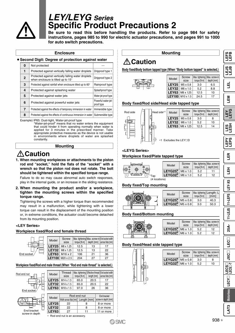
End socket
Rod end nut
End socket
End bracketscrew-in depth
Tap(4 locations)
L
Rod side Head side*1
Body fixed/Body bottom tapped type (When “Body bottom tapped” is selected.)
Body fixed/Rod side/Head side tapped type
Mounting
Caution
*1 Excludes the LEYlD
Workpiece fixed/Rod end male thread (When “Rod end male thread” is selected.)
* Rod end nut is an accessory.
Mounting
Caution1. When mounting workpieces or attachments to the piston
rod end “socket,” hold the flats of the “socket” with a wrench so that the piston rod does not rotate. The bolt should be tightened within the specified torque range.Failure to do so may cause abnormal auto switch responses, play in the internal guide, or an increase in the sliding resistance.
2. When mounting the product and/or a workpiece, tighten the mounting screws within the specified torque range.Tightening the screws with a higher torque than recommended may result in a malfunction, while tightening with a lower torque can result in the displacement of the mounting position or, in extreme conditions, the actuator could become detached from its mounting position.
Workpiece fixed/Rod end female thread
Enclosure
¡Second Digit: Degree of protection against water
Example) IP65: Dust-tight, Water-jet-proof type“Water-jet-proof” means that no water enters the equipment that could hinder it from operating normally when water is applied for 3 minutes in the prescribed manner. Take appropriate protective measures as the device is not usable in environments where droplets of water are splashed constantly.
Workpiece fixed/Plate tapped type
Body fixed/Top mounting
<LEYG Series>
Body fixed/Bottom mounting
Body fixed/Head side tapped type
<LEY Series>
LEY/LEYG SeriesSpecific Product Precautions 2Be sure to read this before handling the products. Refer to page 984 for safety instructions, pages 985 to 990 for electric actuator precautions, and pages 991 to 1000 for auto switch precautions.
Model Screwsize
Max. tighteningtorque [N·m]
Max. screw-indepth [mm]
LEYG25ML M5 x 0.8 3.0 8
LEYG32ML M6 x 1.0 5.2 10
Model Screwsize
Max. tighteningtorque [N·m]
Max. screw-indepth [mm]
LEYG25ML M6 x 1.0 5.2 12
LEYG32ML M6 x 1.0 5.2 12
Model Screwsize
Max. tighteningtorque [N·m]
Length: L[mm]
LEYG25ML M5 x 0.8 3.0 40.3
LEYG32ML M5 x 0.8 3.0 50.3
Model Screwsize
Max. tighteningtorque [N·m]
Max. screw-indepth [mm]
LEYG25ML M6 x 1.0 5.2 11
LEYG32ML M6 x 1.0 5.2 12
0 Not protected —
1 Protected against vertically falling water droplets Dripproof type 1
2 Protected against vertically falling water droplets when enclosure is tilted up to 15° Dripproof type 2
3 Protected against rainfall when enclosure tilted up to 60° Rainproof type
4 Protected against splashing water Splashproof type
5 Protected against water jets Water-jet-proof type
6 Protected against powerful water jetsPowerful water-jet-proof type
7 Protected against the effects of temporary immersion in water Immersible type
8 Protected against the effects of continuous immersion in water Submersible type
Model Screwsize
Max. tighteningtorque [N·m]
Max. screw-indepth [mm]
End socket widthacross flats [mm]
LEY25 M8 x 1.25 12.5 13 17LEY32 M8 x 1.25 12.5 13 22LEY63 M16 x 2 106 21 36LEY100 M20 x 2.5 204 27 27
ModelRod end nut End bracket
screw-in depth [mm]Width across flats [mm] Length [mm]LEY25 22 8 8 or moreLEY32 22 8 8 or moreLEY63 27 11 11 or more
Model Threadsize
Max. tighteningtorque [N·m]
Effective threadlength [mm]
End socket widthacross flats [mm]
LEY25 M14 x 1.5 65.0 20.5 17LEY32 M14 x 1.5 65.0 20.5 22LEY63 M18 x 1.5 97.0 26 36
Model Screwsize
Max. tighteningtorque [N·m]
Max. screw-indepth [mm]
LEY25 M5 x 0.8 3.0 8LEY32 M6 x 1.0 5.2 10LEY63 M8 x 1.25 12.5 14
Model Screwsize
Max. tighteningtorque [N·m]
Max. screw-indepth [mm]
LEY25 M5 x 0.8 3.0 6.5LEY32 M6 x 1.0 5.2 8.8LEY63 M8 x 1.25 12.5 10LEY100 M10 x 1.5 24.5 17
938
LE
FS
LE
FB
LE
LL
EJS
LE
JBL
EM
LE
YL
EY
GL
ES
LE
SH
LE
PY
LE
PS
LE
RL
EH
LEY-
X511
-LEF
S11
-LEJ
S25
A-
Moto
rless
LEC
Y�LE
CS
�LE
CS�-
TJX
C�
LE
C�
LA
T3
b
Maintenance
Warning1. Ensure that the power supply is stopped and the
workpiece is removed before starting maintenance work or replacing the product.
¡Maintenance frequencyPerform maintenance according to the table below.
¡Items for visual appearance check1. Loose set screws, Abnormal amount of dirt, etc.2. Check for visible damage, Check of cable joint3. Vibration, Noise
¡Items for belt checkStop operation immediately and replace the belt when any of the following occur. In addition, ensure your operating environment and conditions satisfy the requirements specified for the product.a. Tooth shape canvas is worn out
Canvas fiber becomes fuzzy, Rubber is coming off and the fiber has become whitish, Lines of fibers have become unclear
b. Peeling off or wearing of the side of the beltBelt corner has become rounded and frayed threads sticks out
c. Belt partially cutBelt is partially cut, Foreign matter caught in the teeth of other parts is causing damage
d. A vertical line on belt teeth is visibleDamage which is made when the belt runs on the flange
e. Rubber back of the belt is softened and sticky f. Cracks on the back of the belt are visible
2. For IP65 equivalent type, apply grease on the piston rod periodically. Grease should be applied at 1 million cycles or 200 km, whichever comes first.· Grease pack order number: GR-S-010 (10 g)/GR-S-020 (20 g)
∗1 Select whichever comes first.
3. Keep the flatness of the mounting surface within the following ranges when mounting the actuator body and workpiece.Mounting the product on an uneven workpiece or base may result in an increase in the sliding resistance.
Mounting
Caution
LEY/LEYG Series Specific Product Precautions 3Be sure to read this before handling the products. Refer to page 984 for safety instructions, pages 985 to 990 for electric actuator precautions, and pages 991 to 1000 for auto switch precautions.
Model Mounting position Flatness
LEYl Body/Body bottom0.1 mmor less
LEYGl
Top mounting/Bottom mounting
0.02 mmor less
Workpiece/Plate mounting0.02 mmor less
Frequency Appearance check Belt checkInspection before daily operation —Inspection every 6 months/250 km/5 million cycles∗1
939
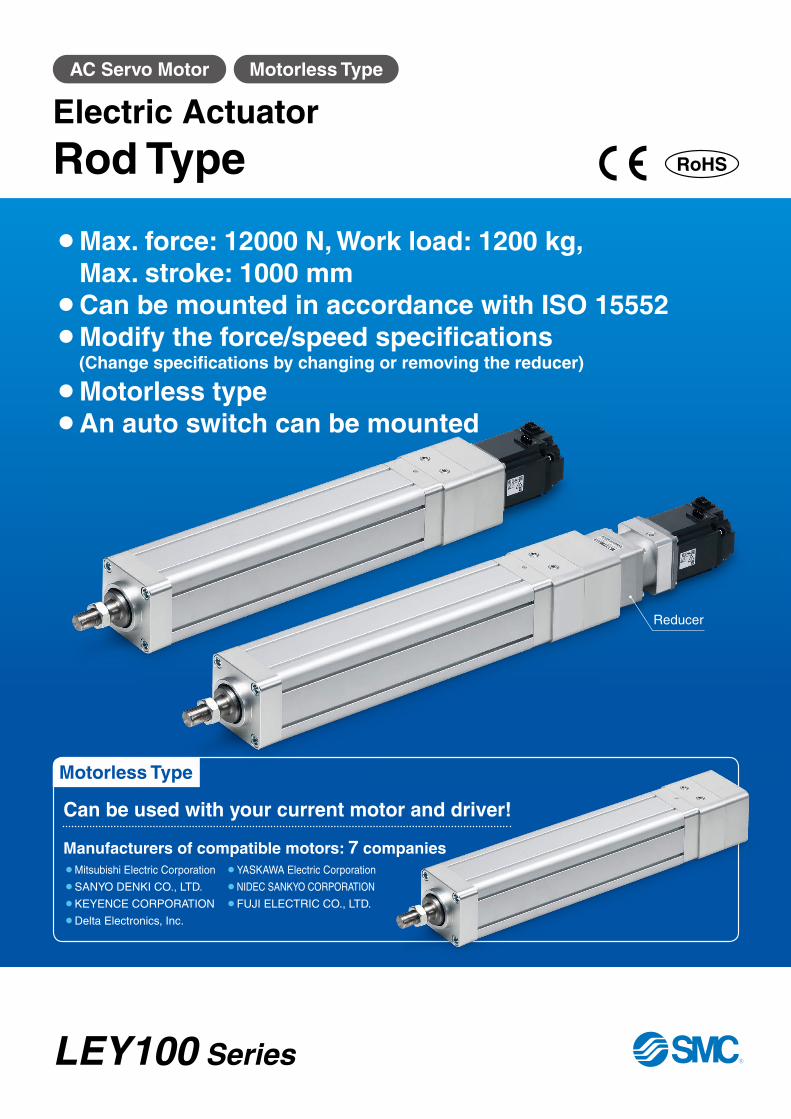
Motorless Type
AC Servo Motor Motorless Type
¡ Max. force: 12000 N, Work load: 1200 kg, Max. stroke: 1000 mm
¡Can be mounted in accordance with ISO 15552¡Modify the force/speed specifications
(Change specifications by changing or removing the reducer)
¡Motorless type¡An auto switch can be mounted
Reducer
Manufacturers of compatible motors: 7 companies
Can be used with your current motor and driver!
¡Mitsubishi Electric Corporation ¡YASKAWA Electric Corporation
¡SANYO DENKI CO., LTD. ¡NIDEC SANKYO CORPORATION
¡KEYENCE CORPORATION ¡FUJI ELECTRIC CO., LTD.
¡Delta Electronics, Inc.
Electric Actuator
Rod Type
LEY100 Series
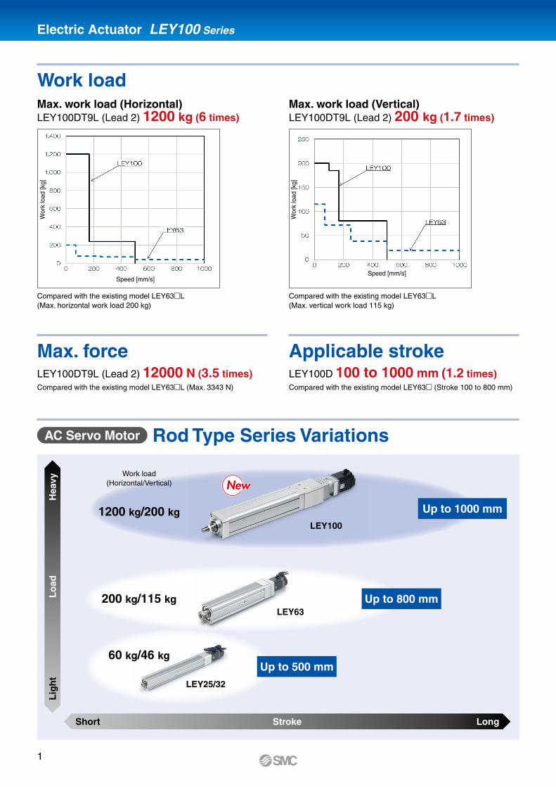
Short
Lig
ht
Stroke
Lo
ad
Long
Hea
vy
Up to 1000 mm
Up to 800 mm
Up to 500 mm
Electric Actuator LEY100 Series
Work load
Max. force Applicable stroke
AC Servo Motor Rod Type Series Variations
LEY100DT9L (Lead 2) 12000 N (3.5 times)Compared with the existing model LEY63mL (Max. 3343 N)
LEY100D 100 to 1000 mm (1.2 times)Compared with the existing model LEY63m (Stroke 100 to 800 mm)
Max. work load (Horizontal)LEY100DT9L (Lead 2) 1200 kg (6 times)
Max. work load (Vertical)LEY100DT9L (Lead 2) 200 kg (1.7 times)
Compared with the existing model LEY63mL(Max. horizontal work load 200 kg)
Compared with the existing model LEY63mL(Max. vertical work load 115 kg)
LEY100
LEY63
LEY25/32
1200 kg/200 kg
200 kg/115 kg
60 kg/46 kg
Work load(Horizontal/Vertical)
Speed [mm/s]
Wor
k lo
ad [k
g]
Wor
k lo
ad [k
g]
Speed [mm/s]
1
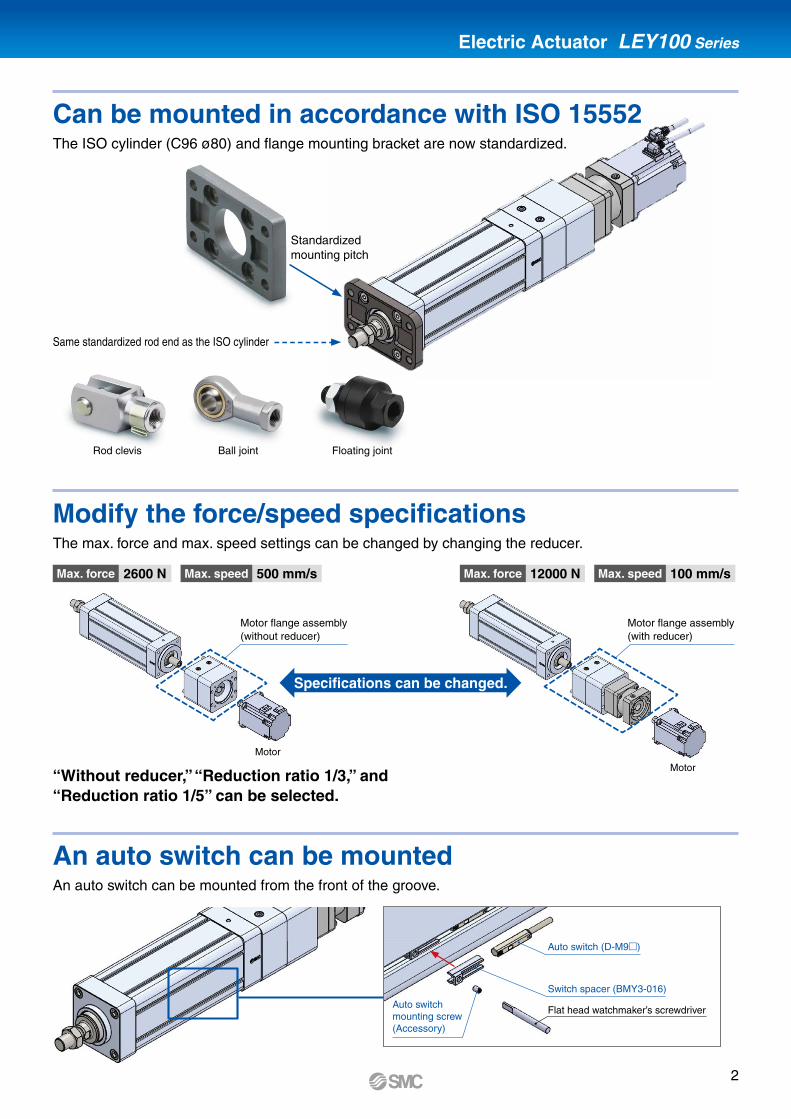
Electric Actuator LEY100 Series
The ISO cylinder (C96 ø80) and flange mounting bracket are now standardized.
The max. force and max. speed settings can be changed by changing the reducer.
An auto switch can be mounted from the front of the groove.
2600 N 12000 N500 mm/s 100 mm/s
Standardized mounting pitch
Same standardized rod end as the ISO cylinder
Rod clevis Ball joint Floating joint
“Without reducer,” “Reduction ratio 1/3,” and “Reduction ratio 1/5” can be selected.
Motor flange assembly(without reducer)
Motor
Motor
Motor flange assembly(with reducer)
Switch spacer (BMY3-016)
Auto switch mounting screw (Accessory)
Flat head watchmaker’s screwdriver
Auto switch (D-M9m)
Can be mounted in accordance with ISO 15552
Modify the force/speed specifications
An auto switch can be mounted
Max. force Max. forceMax. speed Max. speed
Specifications can be changed.
2
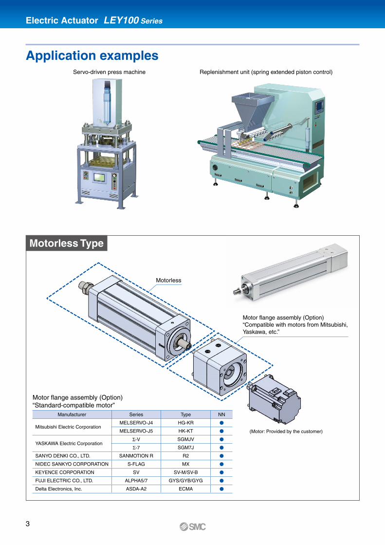
Electric Actuator LEY100 Series
Motor flange assembly (Option)“Standard-compatible motor”
Manufacturer Series Type NN
Mitsubishi Electric CorporationMELSERVO-J4 HG-KR V
MELSERVO-J5 HK-KT V
YASKAWA Electric CorporationΣ-V SGMJV V
Σ-7 SGM7J V
SANYO DENKI CO., LTD. SANMOTION R R2 V
NIDEC SANKYO CORPORATION S-FLAG MX V
KEYENCE CORPORATION SV SV-M/SV-B V
FUJI ELECTRIC CO., LTD. ALPHA5/7 GYS/GYB/GYG V
Delta Electronics, Inc. ASDA-A2 ECMA V
Servo-driven press machine Replenishment unit (spring extended piston control)
Motorless
Motor flange assembly (Option)“Compatible with motors from Mitsubishi, Yaskawa, etc.”
(Motor: Provided by the customer)
Application examples
Motorless Type
3
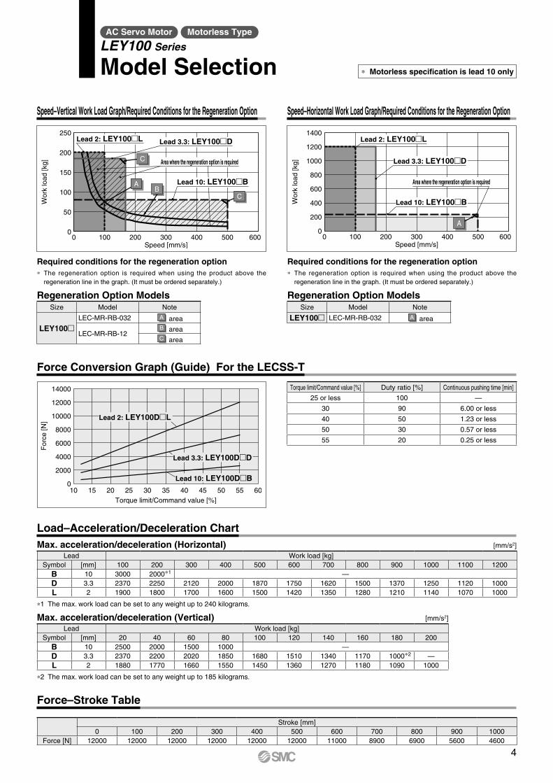
Speed [mm/s]
Wor
k lo
ad [k
g]
0
50
100
150
250
200
0 100 200 300 400 500 600
Lead 10: LEY100�B
Area where the regeneration option is required
Lead 3.3: LEY100�DLead 2: LEY100�L
AB
C
C
Speed [mm/s]
Wor
k lo
ad [k
g]
0
200
400
600
800
1200
1000
1400
0 100 200 300 400 600500
Lead 3.3: LEY100�D
Area where the regeneration option is required
Lead 10: LEY100�B
Lead 2: LEY100�L
A
AC Servo Motor Motorless Type
LEY100 Series
Model Selection
Speed–Vertical Work Load Graph/Required Conditions for the Regeneration Option
Required conditions for the regeneration option* The regeneration option is required when using the product above the
regeneration line in the graph. (It must be ordered separately.)
Regeneration Option ModelsSize Model Note
LEY100mLEC-MR-RB-032 A area
LEC-MR-RB-12B areaC area
Speed–Horizontal Work Load Graph/Required Conditions for the Regeneration Option
Required conditions for the regeneration option* The regeneration option is required when using the product above the
regeneration line in the graph. (It must be ordered separately.)
Regeneration Option ModelsSize Model Note
LEY100m LEC-MR-RB-032 A area
Force Conversion Graph (Guide) For the LECSS-T
Load–Acceleration/Deceleration Chart
Force–Stroke Table
Torque limit/Command value [%] Duty ratio [%] Continuous pushing time [min]
25 or less 100 —
30 90 6.00 or less
40 50 1.23 or less
50 30 0.57 or less
55 20 0.25 or less
10 15 20 25 30 35 555040 45 60Torque limit/Command value [%]
For
ce [N
]
14000
12000
10000
8000
6000
4000
2000
0
Lead 3.3: LEY100D�D
Lead 2: LEY100D�L
Lead 10: LEY100D�B
* Motorless specification is lead 10 only
Max. acceleration/deceleration (Horizontal) [mm/s2]
Lead Work load [kg]Symbol [mm] 100 200 300 400 500 600 700 800 900 1000 1100 1200
B 10 3000 2000*1 —D 3.3 2370 2250 2120 2000 1870 1750 1620 1500 1370 1250 1120 1000L 2 1900 1800 1700 1600 1500 1420 1350 1280 1210 1140 1070 1000
*1 The max. work load can be set to any weight up to 240 kilograms.
Max. acceleration/deceleration (Vertical) [mm/s2]
Lead Work load [kg]Symbol [mm] 20 40 60 80 100 120 140 160 180 200
B 10 2500 2000 1500 1000 —D 3.3 2370 2200 2020 1850 1680 1510 1340 1170 1000*2 —L 2 1880 1770 1660 1550 1450 1360 1270 1180 1090 1000
*2 The max. work load can be set to any weight up to 185 kilograms.
Stroke [mm]0 100 200 300 400 500 600 700 800 900 1000
Force [N] 12000 12000 12000 12000 12000 12000 11000 8900 6900 5600 4600
4
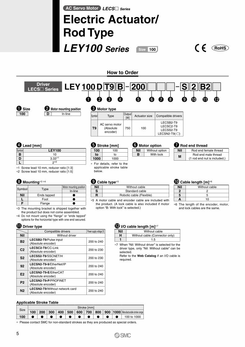
AC Servo Motor LECS Series
Electric Actuator/Rod TypeLEY100 Series 100Size
w y !0i oe r tq u !1 !2
How to Order
!0 Cable length [m]*6
Nil Without cable2 25 5A 10
*6 The length of the encoder, motor, and lock cables are the same.
o Cable type*5
Nil Without cableS Standard cableR Robotic cable (Flexible)
*5 A motor cable and encoder cable are included with the product. (A lock cable is also included if motor option “B: With lock” is selected.)
i Mounting*3 *4
Symbol TypeMotor mounting position
In-lineNil Ends tapped V
L Foot V
F Flange V
*3 The mounting bracket is shipped together with the product but does not come assembled.
*4 Do not mount using the “flange” or “ends tapped” options for the horizontal type with one end secured.
t Stroke [mm]100 100to to
1000 1000
* For details, refer to the applicable stroke table below.
r Lead [mm]Symbol LEY100B 10D 3.33*1
L 2*2
*1 Screw lead 10 mm, reducer ratio [1:3]*2 Screw lead 10 mm, reducer ratio [1:5]
u Rod end threadNil Rod end female thread
M Rod end male thread(1 rod end nut is included.)
y Motor optionNil Without optionB With lock
q Size100
w Motor mounting positionD In-line
Applicable Stroke Table
SizeStroke [mm]
100 200 300 400 500 600 700 800 900 1000 Manufacturable stroke range
100 V V V V V V V V V V 100 to 1000
* Please contact SMC for non-standard strokes as they are produced as special orders.
e Motor type
Symbol TypeOutput
[W]Actuator size Compatible drivers
T9AC servo motor
(Absolute encoder)
750 100
LECSB2-T9LECSC2-T9LECSS2-T9
LECSN2-T9(-)
LEY 100 D T9 B 200 S 2 B2DriverLECS Series
!2 I/O cable length [m]*7
Nil Without cableH Without cable (Connector only)1 1.5
*7 When “Nil: Without driver” is selected for the driver type, only “Nil: Without cable” can be selected.Refer to the Web Catalog if an I/O cable is required.
!1 Driver typeCompatible drivers Power supply voltage [V]
Nil Without driver
B2 LECSB2-T9/Pulse input(Absolute encoder)
200 to 240
C2 LECSC2-T9/CC-Link(Absolute encoder)
200 to 230
S2 LECSS2-T9/SSCNET/H(Absolute encoder)
200 to 230
92 LECSN2-T9-9/EtherNet/IP(Absolute encoder)
200 to 240
E2 LECSN2-T9-E/EtherCAT(Absolute encoder)
200 to 240
P2 LECSN2-T9-P/PROFINET(Absolute encoder)
200 to 240
N2 LECSN2-T9/Without network card(Absolute encoder)
200 to 240
5
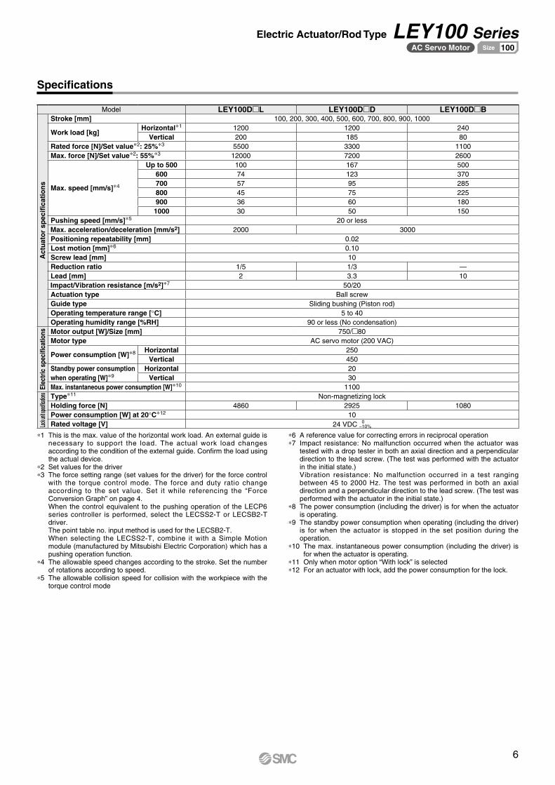
6
Electric Actuator/Rod Type LEY100 SeriesAC Servo Motor 100Size
Specifications
Model LEY100DmL LEY100DmD LEY100DmB
Act
uat
or
spec
ifica
tio
ns
Stroke [mm] 100, 200, 300, 400, 500, 600, 700, 800, 900, 1000
Work load [kg]Horizontal*1 1200 1200 240
Vertical 200 185 80Rated force [N]/Set value*2: 25%*3 5500 3300 1100Max. force [N]/Set value*2: 55%*3 12000 7200 2600
Max. speed [mm/s]*4
Up to 500 100 167 500600 74 123 370700 57 95 285800 45 75 225900 36 60 180
1000 30 50 150Pushing speed [mm/s]*5 20 or lessMax. acceleration/deceleration [mm/s2] 2000 3000Positioning repeatability [mm] 0.02Lost motion [mm]*6 0.10Screw lead [mm] 10Reduction ratio 1/5 1/3 —Lead [mm] 2 3.3 10Impact/Vibration resistance [m/s2]*7 50/20Actuation type Ball screwGuide type Sliding bushing (Piston rod)Operating temperature range [°C] 5 to 40Operating humidity range [%RH] 90 or less (No condensation)
Elec
tric
spe
cific
atio
ns Motor output [W]/Size [mm] 750/m80Motor type AC servo motor (200 VAC)
Power consumption [W]*8 Horizontal 250Vertical 450
Standby power consumption when operating [W]*9
Horizontal 20Vertical 30
Max. instantaneous power consumption [W]*10 1100
Lock u
nit spe
cificat
ions Type*11 Non-magnetizing lock
Holding force [N] 4860 2925 1080Power consumption [W] at 20°C*12 10Rated voltage [V] 24 VDC 0−10%
*1 This is the max. value of the horizontal work load. An external guide is necessary to support the load. The actual work load changes according to the condition of the external guide. Confirm the load using the actual device.
*2 Set values for the driver*3 The force setting range (set values for the driver) for the force control
with the torque control mode. The force and duty ratio change according to the set value. Set it while referencing the “Force Conversion Graph” on page 4.When the control equivalent to the pushing operation of the LECP6 series controller is performed, select the LECSS2-T or LECSB2-T driver.The point table no. input method is used for the LECSB2-T.When selecting the LECSS2-T, combine it with a Simple Motion module (manufactured by Mitsubishi Electric Corporation) which has a pushing operation function.
*4 The allowable speed changes according to the stroke. Set the number of rotations according to speed.
*5 The allowable collision speed for collision with the workpiece with the torque control mode
*6 A reference value for correcting errors in reciprocal operation*7 Impact resistance: No malfunction occurred when the actuator was
tested with a drop tester in both an axial direction and a perpendicular direction to the lead screw. (The test was performed with the actuator in the initial state.)Vibration resistance: No malfunction occurred in a test ranging between 45 to 2000 Hz. The test was performed in both an axial direction and a perpendicular direction to the lead screw. (The test was performed with the actuator in the initial state.)
*8 The power consumption (including the driver) is for when the actuator is operating.
*9 The standby power consumption when operating (including the driver) is for when the actuator is stopped in the set position during the operation.
*10 The max. instantaneous power consumption (including the driver) is for when the actuator is operating.
*11 Only when motor option “With lock” is selected*12 For an actuator with lock, add the power consumption for the lock.
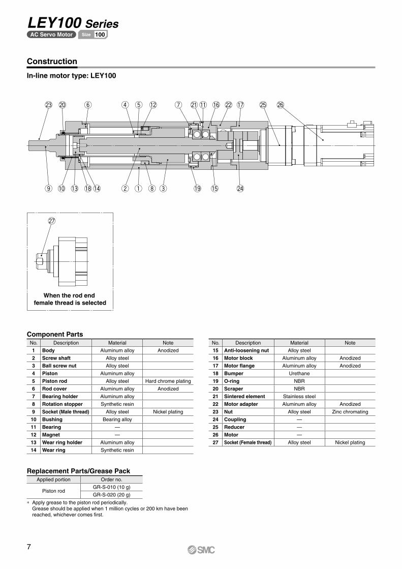
@3
o !0 !3 !8!4 w q i e !9 !5 @4
@7
@0 y r t !2 u @1!1 !6 @2 !7 @5 @6
When the rod end female thread is selected
Component PartsNo. Description Material Note
1 Body Aluminum alloy Anodized
2 Screw shaft Alloy steel
3 Ball screw nut Alloy steel
4 Piston Aluminum alloy
5 Piston rod Alloy steel Hard chrome plating
6 Rod cover Aluminum alloy Anodized
7 Bearing holder Aluminum alloy
8 Rotation stopper Synthetic resin
9 Socket (Male thread) Alloy steel Nickel plating
10 Bushing Bearing alloy
11 Bearing —
12 Magnet —
13 Wear ring holder Aluminum alloy
14 Wear ring Synthetic resin
No. Description Material Note
15 Anti-loosening nut Alloy steel
16 Motor block Aluminum alloy Anodized
17 Motor flange Aluminum alloy Anodized
18 Bumper Urethane
19 O-ring NBR
20 Scraper NBR
21 Sintered element Stainless steel
22 Motor adapter Aluminum alloy Anodized
23 Nut Alloy steel Zinc chromating
24 Coupling —
25 Reducer —
26 Motor —
27 Socket (Female thread) Alloy steel Nickel plating
Construction
In-line motor type: LEY100
Replacement Parts/Grease PackApplied portion Order no.
Piston rodGR-S-010 (10 g)
GR-S-020 (20 g)
* Apply grease to the piston rod periodically.Grease should be applied when 1 million cycles or 200 km have been reached, whichever comes first.
7
LEY100 SeriesAC Servo Motor 100Size
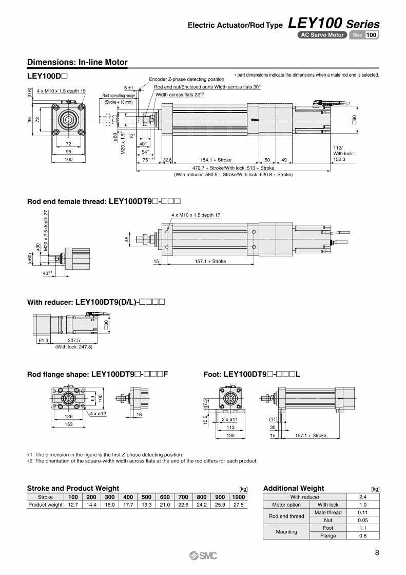
7295
472.7 + Stroke/With lock: 513 + Stroke(With reducer: 580.5 + Stroke/With lock: 620.8 + Stroke)
154.1 + Stroke32.675∗ ∗1
54∗40∗
4950
�80
(ø60
)
61.3 207.5(With lock: 247.8)
157.1 + Stroke
45
153
126
100
63
130
113
(47.
5)
157.1 + Stroke
(9.6
)
4 x M10 x 1.5 depth 15
Encoder Z-phase detecting position
Rod operating range(Stroke + 10 mm)
ø60
M20
x 1
.5∗
12∗
Width across flats 22∗2
112/With lock: 152.3
M20
x 2
.5 d
epth
27
ø30
43∗1
15
4 x M10 x 1.5 depth 17
4 x ø12 16
15.5 2 x ø11
15
30
(11)
5 ±1
�80
Rod end nut/Enclosed parts Width across flats 30∗
100
95
72
Dimensions: In-line Motor
Rod end female thread: LEY100DT9m-mmm
LEY100Dm
With reducer: LEY100DT9(D/L)-mmmm
Rod flange shape: LEY100DT9m-mmmF Foot: LEY100DT9m-mmmL
*1 The dimension in the figure is the first Z-phase detecting position.*2 The orientation of the square-width width across flats at the end of the rod differs for each product.
Stroke and Product Weight [kg]
Stroke 100 200 300 400 500 600 700 800 900 1000Product weight 12.7 14.4 16.0 17.7 19.3 21.0 22.6 24.2 25.9 27.5
Additional Weight [kg]
With reducer 2.4
Motor option With lock 1.0
Rod end threadMale thread 0.11
Nut 0.05
MountingFoot 1.1
Flange 0.8
* part dimensions indicate the dimensions when a male rod end is selected.
8
Electric Actuator/Rod Type LEY100 SeriesAC Servo Motor 100Size
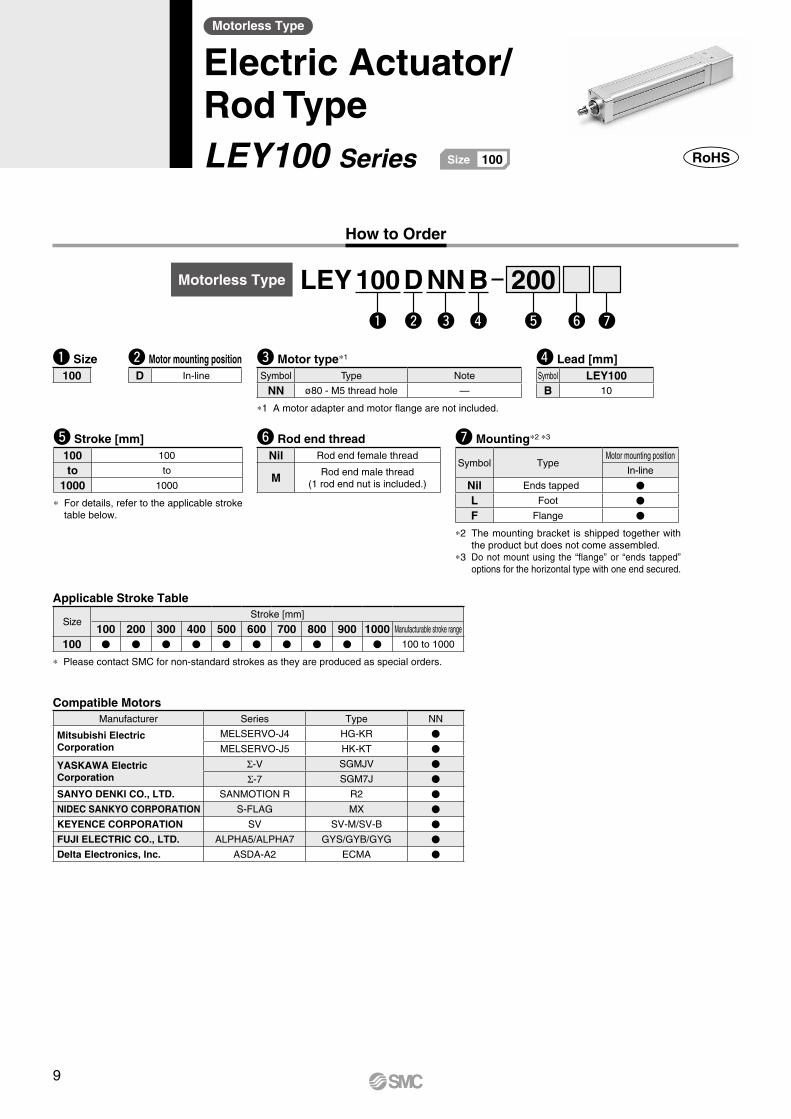
How to Order
Motorless Type
Electric Actuator/Rod TypeLEY100 Series 100Size
w ye r tq u
u Mounting*2 *3
Symbol TypeMotor mounting position
In-line
Nil Ends tapped V
L Foot V
F Flange V
*2 The mounting bracket is shipped together with the product but does not come assembled.
*3 Do not mount using the “flange” or “ends tapped” options for the horizontal type with one end secured.
t Stroke [mm]100 100
to to
1000 1000
* For details, refer to the applicable stroke table below.
r Lead [mm]Symbol LEY100B 10
y Rod end threadNil Rod end female thread
M Rod end male thread(1 rod end nut is included.)
q Size100
w Motor mounting positionD In-line
Applicable Stroke Table
SizeStroke [mm]
100 200 300 400 500 600 700 800 900 1000 Manufacturable stroke range
100 V V V V V V V V V V 100 to 1000
* Please contact SMC for non-standard strokes as they are produced as special orders.
e Motor type*1
Symbol Type Note
NN ø80 - M5 thread hole —
*1 A motor adapter and motor flange are not included.
Motorless Type LEY 100 D NN B 200
Compatible MotorsManufacturer Series Type NN
Mitsubishi Electric Corporation
MELSERVO-J4 HG-KR V
MELSERVO-J5 HK-KT V
YASKAWA Electric Corporation
Σ-V SGMJV V
Σ-7 SGM7J V
SANYO DENKI CO., LTD. SANMOTION R R2 V
NIDEC SANKYO CORPORATION S-FLAG MX V
KEYENCE CORPORATION SV SV-M/SV-B V
FUJI ELECTRIC CO., LTD. ALPHA5/ALPHA7 GYS/GYB/GYG V
Delta Electronics, Inc. ASDA-A2 ECMA V
9
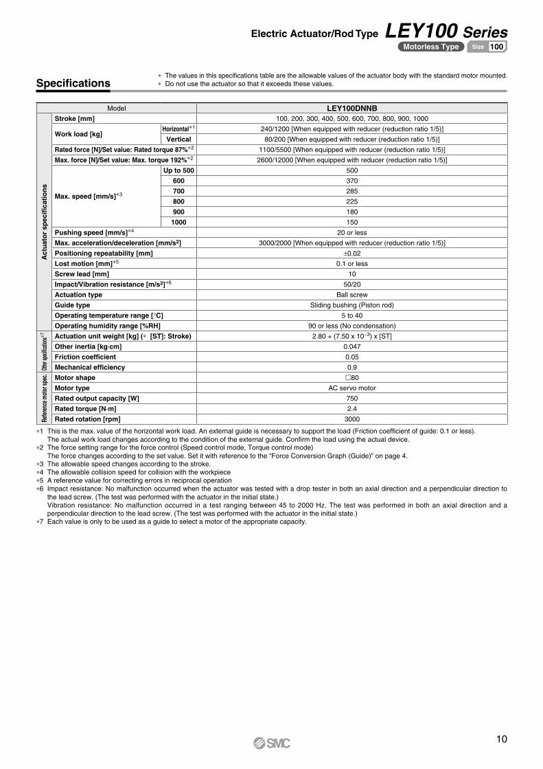
Specifications
Model LEY100DNNB
Act
uat
or
spec
ifica
tio
ns
Stroke [mm] 100, 200, 300, 400, 500, 600, 700, 800, 900, 1000
Work load [kg]Horizontal*1 240/1200 [When equipped with reducer (reduction ratio 1/5)]
Vertical 80/200 [When equipped with reducer (reduction ratio 1/5)]
Rated force [N]/Set value: Rated torque 87%*2 1100/5500 [When equipped with reducer (reduction ratio 1/5)]
Max. force [N]/Set value: Max. torque 192%*2 2600/12000 [When equipped with reducer (reduction ratio 1/5)]
Max. speed [mm/s]*3
Up to 500 500
600 370
700 285
800 225
900 180
1000 150
Pushing speed [mm/s]*4 20 or less
Max. acceleration/deceleration [mm/s2] 3000/2000 [When equipped with reducer (reduction ratio 1/5)]
Positioning repeatability [mm] ±0.02
Lost motion [mm]*5 0.1 or less
Screw lead [mm] 10
Impact/Vibration resistance [m/s2]*6 50/20
Actuation type Ball screw
Guide type Sliding bushing (Piston rod)
Operating temperature range [°C] 5 to 40
Operating humidity range [%RH] 90 or less (No condensation)
Other
specifi
cation
s*7 Actuation unit weight [kg] (* [ST]: Stroke) 2.80 + (7.50 x 10⁻³) x [ST]
Other inertia [kg·cm] 0.047
Friction coefficient 0.05
Mechanical efficiency 0.9
Refer
ence
mot
or sp
ec.
Motor shape m80
Motor type AC servo motor
Rated output capacity [W] 750
Rated torque [N·m] 2.4
Rated rotation [rpm] 3000
*1 This is the max. value of the horizontal work load. An external guide is necessary to support the load (Friction coefficient of guide: 0.1 or less).The actual work load changes according to the condition of the external guide. Confirm the load using the actual device.
*2 The force setting range for the force control (Speed control mode, Torque control mode)The force changes according to the set value. Set it with reference to the “Force Conversion Graph (Guide)” on page 4.
*3 The allowable speed changes according to the stroke.*4 The allowable collision speed for collision with the workpiece*5 A reference value for correcting errors in reciprocal operation*6 Impact resistance: No malfunction occurred when the actuator was tested with a drop tester in both an axial direction and a perpendicular direction to
the lead screw. (The test was performed with the actuator in the initial state.)Vibration resistance: No malfunction occurred in a test ranging between 45 to 2000 Hz. The test was performed in both an axial direction and a perpendicular direction to the lead screw. (The test was performed with the actuator in the initial state.)
*7 Each value is only to be used as a guide to select a motor of the appropriate capacity.
* The values in this specifications table are the allowable values of the actuator body with the standard motor mounted.* Do not use the actuator so that it exceeds these values.
10
Electric Actuator/Rod Type LEY100 SeriesMotorless Type 100Size
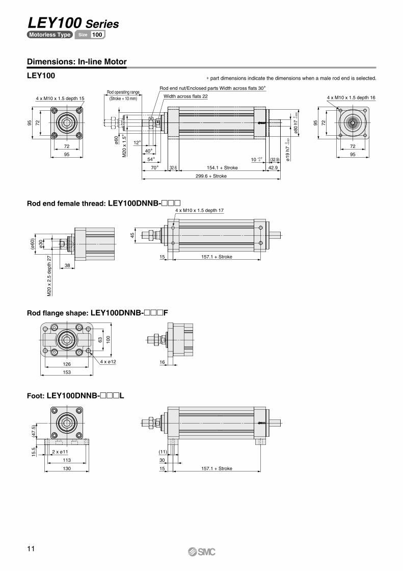
95
72
7295
Rod operating range(Stroke + 10 mm)
Rod end nut/Enclosed parts Width across flats 30∗
Width across flats 22
M20
x 1
.5∗
ø60
12∗
299.6 + Stroke
154.1 + Stroke32.670∗54∗
40∗
10 +0.2 0
42.9
(32.9) ø19
h7
0
−0.
021
ø80
h7 0
−0
.030
7295
95
72
38
M20
x 2
.5 d
epth
27
ø30
(ø60
) 45
15 157.1 + Stroke
4 x M10 x 1.5 depth 17
153
126 4 x ø12
100
63
16
130
113
2 x ø11
15.5
(47.
5)
15
30
(11)
157.1 + Stroke
4 x M10 x 1.5 depth 15 4 x M10 x 1.5 depth 16
Dimensions: In-line Motor
LEY100
Rod end female thread: LEY100DNNB-mmm
Rod flange shape: LEY100DNNB-mmmF
Foot: LEY100DNNB-mmmL
* part dimensions indicate the dimensions when a male rod end is selected.
11
LEY100 Seriesモータレス仕様 63サイズMotorless Type 100Size
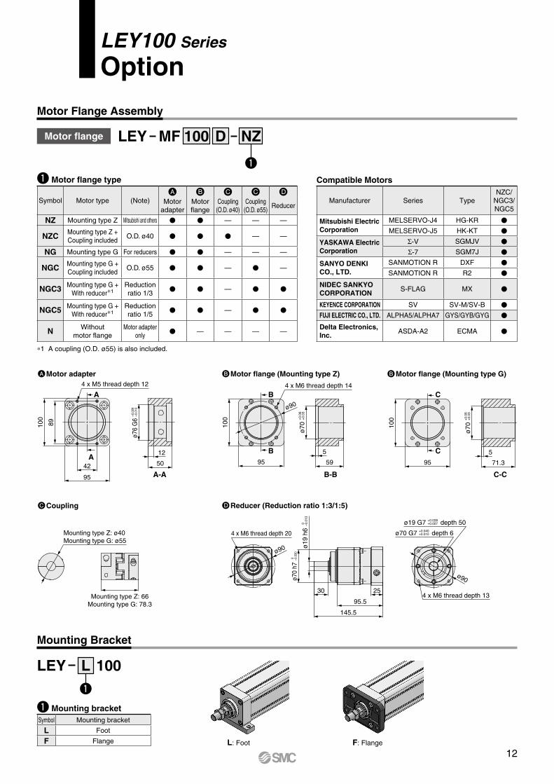
LEY100 Series
Option
Motor Flange Assembly
Mounting Bracket
q
q
Motor flange LEY MF NZD100
q Motor flange type
Symbol Motor type (Note)A B C C D
Motor adapter
Motor flange
Coupling(O.D. ø40)
Coupling(O.D. ø55)
Reducer
NZ Mounting type Z Mitsubishi and others V V — — —
NZC Mounting type Z + Coupling included
O.D. ø40 V V V — —
NG Mounting type G For reducers V V — — —
NGC Mounting type G + Coupling included
O.D. ø55 V V — V —
NGC3 Mounting type G +With reducer*1
Reduction ratio 1/3
V V — V V
NGC5 Mounting type G +With reducer*1
Reduction ratio 1/5
V V — V V
N Without motor flange
Motor adapter only
V — — — —
*1 A coupling (O.D. ø55) is also included.
q Mounting bracketSymbol Mounting bracket
L Foot
F Flange
LEY L 100
L: Foot F: Flange
Compatible Motors
Manufacturer Series TypeNZC/
NGC3/NGC5
Mitsubishi Electric Corporation
MELSERVO-J4 HG-KR V
MELSERVO-J5 HK-KT V
YASKAWA Electric Corporation
Σ-V SGMJV V
Σ-7 SGM7J V
SANYO DENKI CO., LTD.
SANMOTION R DXF V
SANMOTION R R2 V
NIDEC SANKYO CORPORATION
S-FLAG MX V
KEYENCE CORPORATION SV SV-M/SV-B V
FUJI ELECTRIC CO., LTD. ALPHA5/ALPHA7 GYS/GYB/GYG V
Delta Electronics,Inc.
ASDA-A2 ECMA V
CCoupling DReducer (Reduction ratio 1:3/1:5)
C
C
AMotor adapter
A
A
C-C
BMotor flange (Mounting type G)BMotor flange (Mounting type Z)
B
B
B-BA-A95
42
89100
4 x M5 thread depth 12
50
12
ø76
G6
+0.0
29
+0.0
10
100
95
4 x M6 thread depth 14
ø70
+0.
06
+0.
03
59
5
100
95 71.3
5
ø70
+0.
06
+0.
03
Mounting type Z: ø40Mounting type G: ø55
Mounting type Z: 66Mounting type G: 78.3
4 x M6 thread depth 20
ø70
h7 0
−0
.030
ø19
h6
0
−0.
013
30
145.5
95.5
254 x M6 thread depth 13
ø70 G7 +0.040 +0.010 depth 6
ø19 G7 +0.028 +0.007 depth 50
ø90
ø90
ø90
12
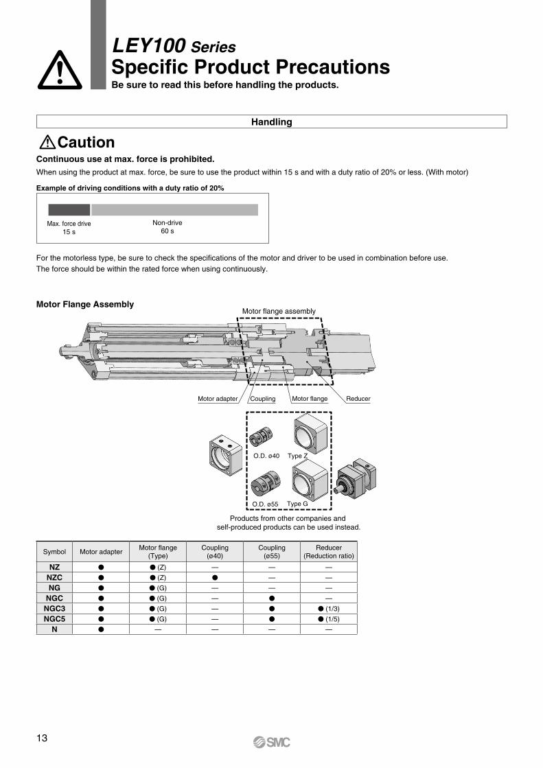
Motor flange assembly
ReducerMotor flangeCouplingMotor adapter
Type Z
Type G
O.D. ø40
O.D. ø55
Products from other companies and self-produced products can be used instead.
Handling
Caution
LEY100 SeriesSpecific Product PrecautionsBe sure to read this before handling the products.
Continuous use at max. force is prohibited.When using the product at max. force, be sure to use the product within 15 s and with a duty ratio of 20% or less. (With motor)
Motor Flange Assembly
For the motorless type, be sure to check the specifications of the motor and driver to be used in combination before use.The force should be within the rated force when using continuously.
Max. force drive15 s
Non-drive60 s
Example of driving conditions with a duty ratio of 20%
Symbol Motor adapterMotor flange
(Type)Coupling
(ø40)Coupling
(ø55)Reducer
(Reduction ratio)
NZ V V (Z) — — —
NZC V V (Z) V — —
NG V V (G) — — —
NGC V V (G) — V —
NGC3 V V (G) — V V (1/3)
NGC5 V V (G) — V V (1/5)
N V — — — —
13
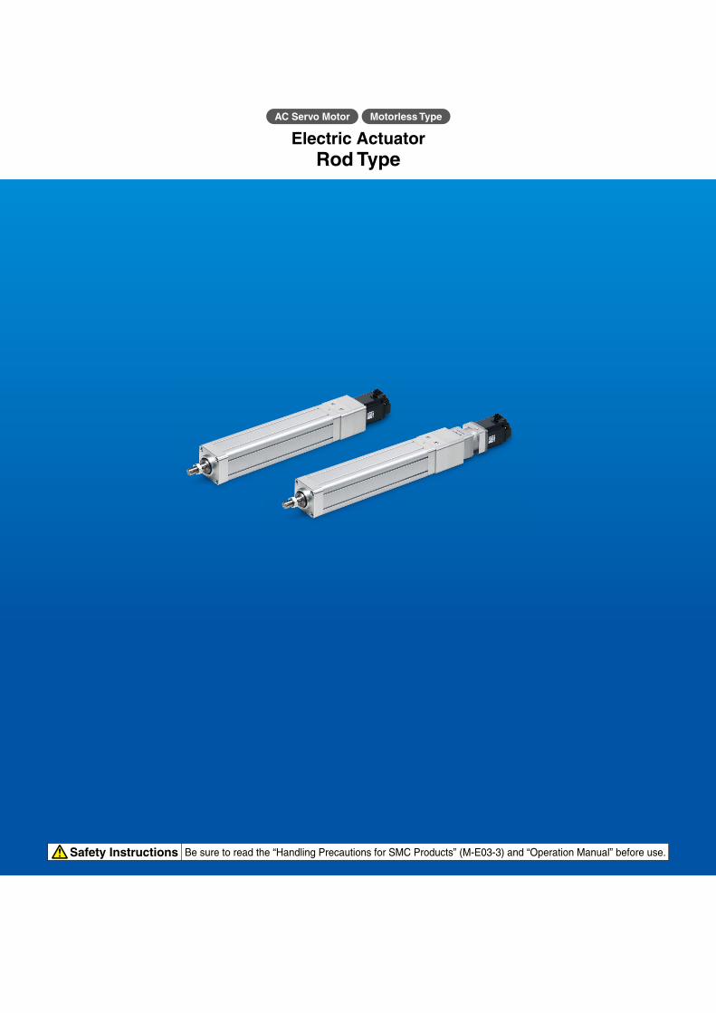
Safety Instructions Be sure to read the “Handling Precautions for SMC Products” (M-E03-3) and “Operation Manual” before use.
Electric ActuatorRod Type
AC Servo Motor Motorless Type

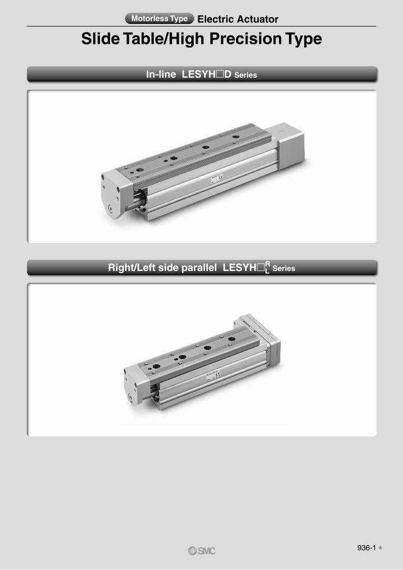
Slide Table/High Precision TypeMotorless Type Electric Actuator
In-line LESYHmD Series
Right/Left side parallel LESYHmRL Series
936-1 A
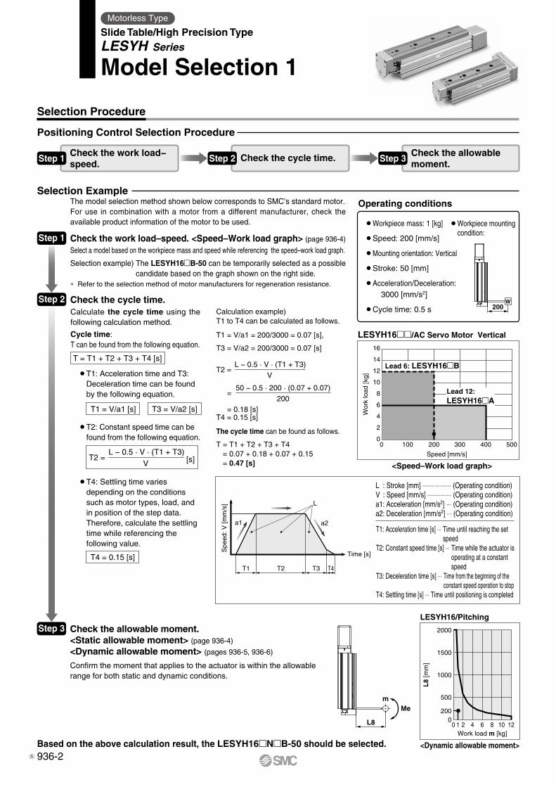
16
14
12
10
8
6
4
2
00 100 200 300 400 500
Speed [mm/s]
Wor
k lo
ad [k
g]Lead 6: LESYH16�B
Lead 12:LESYH16�A
2000
1500
1000
500
00 10 12
200
Work load m [kg]
L8
[mm
]
21 4 6 8
200W
Mem
L8
T1
a1 a2
L
Spe
ed: V
[mm
/s]
Time [s]
T2 T3 T4
Motorless Type
Slide Table/High Precision TypeLESYH Series
Model Selection 1
Selection Procedure
Step 1
Check the cycle time.
<Speed–Work load graph>
Check the work load–speed. <Speed–Work load graph> (page 936-4)
Select a model based on the workpiece mass and speed while referencing the speed–work load graph.
Selection example) The LESYH16B-50 can be temporarily selected as a possible candidate based on the graph shown on the right side.
* Refer to the selection method of motor manufacturers for regeneration resistance.
LESYH16/AC Servo Motor Vertical
Operating conditions
Positioning Control Selection Procedure
Step 3
The model selection method shown below corresponds to SMC’s standard motor.For use in combination with a motor from a different manufacturer, check the available product information of the motor to be used.
Step 2
Check the allowable moment.<Static allowable moment> (page 936-4)
<Dynamic allowable moment> (pages 936-5, 936-6)
Based on the above calculation result, the LESYH16NB-50 should be selected.
Selection Example
Step 1Check the work load−speed.
Step 2 Check the cycle time. Step 3Check the allowablemoment.
<Dynamic allowable moment>
Confirm the moment that applies to the actuator is within the allowable range for both static and dynamic conditions.
T4 = 0.15 [s]
Calculate the cycle time using the following calculation method.
Cycle time:T can be found from the following equation.
T = T1 + T2 + T3 + T4 [s]
¡�T4: Settling time varies depending on the conditions such as motor types, load, and in position of the step data. Therefore, calculate the settling time while referencing the following value.
T2 = [s]L − 0.5 · V · (T1 + T3)
V
¡�T2: Constant speed time can be found from the following equation.
T1 = V/a1 [s] T3 = V/a2 [s]
¡�T1: Acceleration time and T3: Deceleration time can be found by the following equation.
Calculation example)T1 to T4 can be calculated as follows.
T1 = V/a1 = 200/3000 = 0.07 [s],
T3 = V/a2 = 200/3000 = 0.07 [s]
T4 = 0.15 [s]
The cycle time can be found as follows.
T = T1 + T2 + T3 + T4 = 0.07 + 0.18 + 0.07 + 0.15 = 0.47 [s]
T2 =
=
= 0.18 [s]
L − 0.5 · V · (T1 + T3)
V
50 − 0.5 · 200 · (0.07 + 0.07)
200
¡Workpiece mass: 1 [kg]
¡Speed: 200 [mm/s]
¡Mounting orientation: Vertical
¡Stroke: 50 [mm]
¡Ac celeration/Deceleration: 3000 [mm/s2]
¡Cycle time: 0.5 s
¡�Workpiece mounting condition:
LESYH16/Pitching
L : Stroke [mm] ⋅⋅⋅⋅⋅⋅⋅⋅⋅⋅⋅⋅⋅⋅⋅⋅⋅⋅ (Operating condition)V : Speed [mm/s] ⋅⋅⋅⋅⋅⋅⋅⋅⋅⋅⋅⋅⋅⋅⋅ (Operating condition)a1: Acceleration [mm/s2] ⋅⋅⋅ (Operating condition)a2: Deceleration [mm/s2] ⋅⋅⋅ (Operating condition)
T1: Acceleration time [s] ⋅⋅⋅ Time until reaching the set speed
T2: Constant speed time [s] ⋅⋅⋅ Time while the actuator is operating at a constant speed
T3: Deceleration time [s] ⋅⋅⋅ Time from the beginning of the constant speed operation to stop
T4: Settling time [s] ⋅⋅⋅ Time until positioning is completed
936-2A
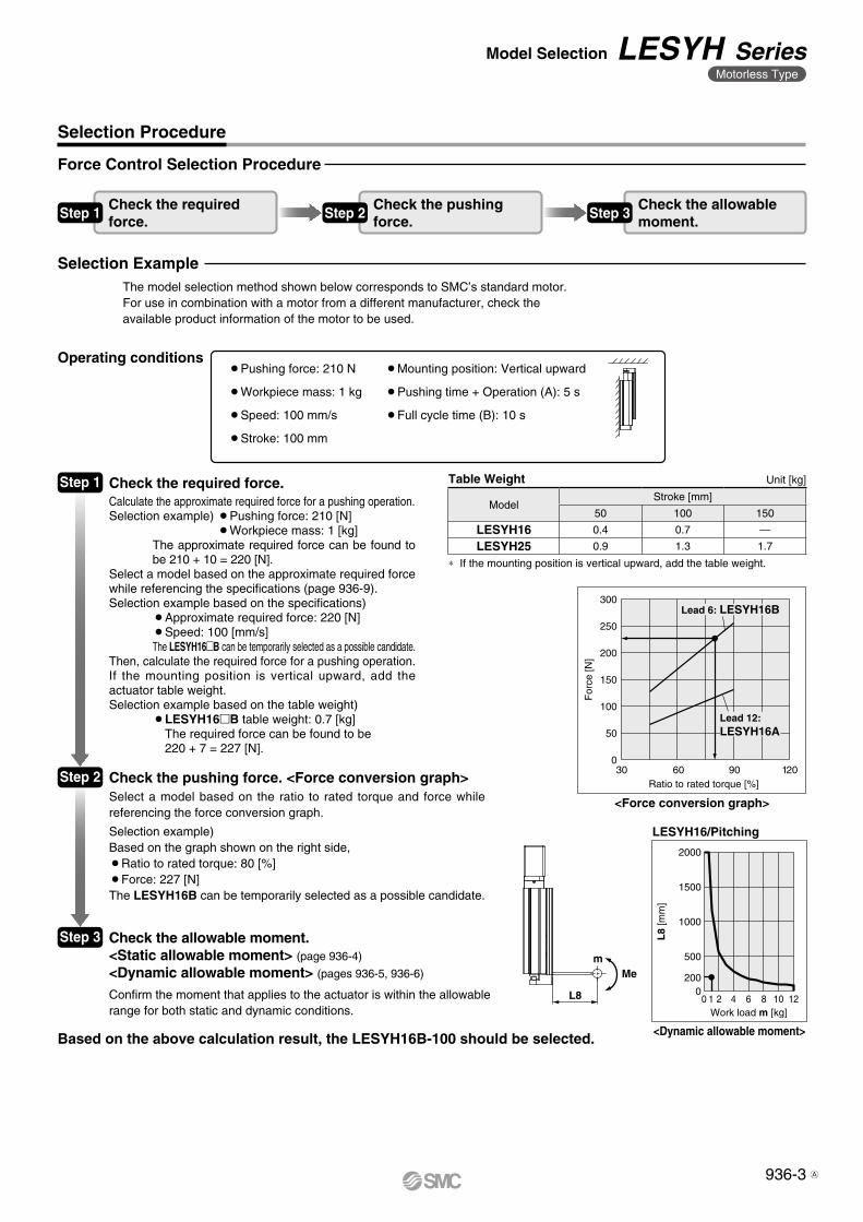
For
ce [N
]
Ratio to rated torque [%]
300
250
200
150
100
50
06030 12090
Lead 12:LESYH16A
Lead 6: LESYH16B
2000
1500
1000
500
00 10 12
Work load m [kg]
L8
[mm
]
200
21 4 6 8
Mem
L8
Step 2 Check the pushing force. <Force conversion graph>
Force Control Selection Procedure
Select a model based on the ratio to rated torque and force while referencing the force conversion graph.
Selection example)Based on the graph shown on the right side,¡Ratio to rated torque: 80 [%]¡Force: 227 [N]The LESYH16B can be temporarily selected as a possible candidate.
The model selection method shown below corresponds to SMC’s standard motor.For use in combination with a motor from a different manufacturer, check the available product information of the motor to be used.
<Force conversion graph>
Selection Procedure
Based on the above calculation result, the LESYH16B-100 should be selected.
Check the required force.Calculate the approximate required force for a pushing operation.Selection example) ¡Pushing force: 210 [N]
¡Workpiece mass: 1 [kg]The approximate required force can be found to be 210 + 10 = 220 [N].
Select a model based on the approximate required force while referencing the specifications (page 936-9).Selection example based on the specifications)
¡Approximate required force: 220 [N]¡Speed: 100 [mm/s]The LESYH16B can be temporarily selected as a possible candidate.
Then, calculate the required force for a pushing operation.If the mounting position is vertical upward, add the actuator table weight.Selection example based on the table weight)
¡�LESYH16B table weight: 0.7 [kg] The required force can be found to be 220 + 7 = 227 [N].
Step 3
<Dynamic allowable moment>
LESYH16/Pitching
Step 1Model
Stroke [mm]
50 100 150
LESYH16 0.4 0.7 —
LESYH25 0.9 1.3 1.7
¡Pushing force: 210 N
¡Workpiece mass: 1 kg
¡Speed: 100 mm/s
¡Stroke: 100 mm
¡Mounting position: Vertical upward
¡Pushing time + Operation (A): 5 s
¡Full cycle time (B): 10 s
Operating conditions
Check the required force.
Check the pushing force.
Check the allowable moment.
Table Weight
* If the mounting position is vertical upward, add the table weight.
Unit [kg]
Selection Example
Step 1 Step 2 Step 3
Check the allowable moment.<Static allowable moment> (page 936-4)
<Dynamic allowable moment> (pages 936-5, 936-6)
Confirm the moment that applies to the actuator is within the allowable range for both static and dynamic conditions.
936-3
Model Selection LESYH SeriesMotorless Type
A
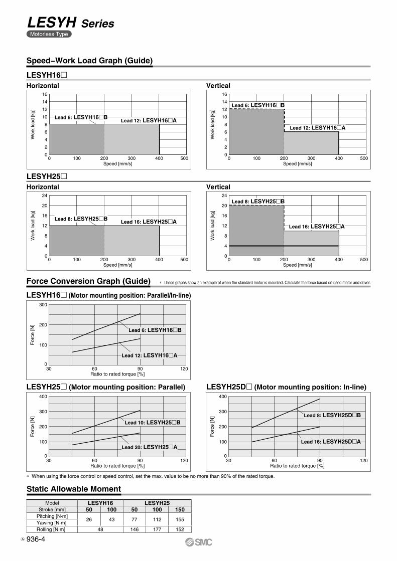
Speed [mm/s]
16
14
12
10
8
6
4
2
0
Wor
k lo
ad [k
g]
0 100 200 300 400 500
Lead 6: LESYH16�BLead 12: LESYH16�A
Speed [mm/s]
24
20
16
12
8
4
0
Wor
k lo
ad [k
g]
0 100 200 300 400 500
Lead 8: LESYH25�B Lead 16: LESYH25�A
Speed [mm/s]
16
14
12
10
8
6
4
2
0
Wor
k lo
ad [k
g]
0 100 200 300 400 500
Lead 6: LESYH16�B
Lead 12: LESYH16�A
Speed [mm/s]
24
20
16
12
8
4
0
Wor
k lo
ad [k
g]
0 100 200 300 400 500
Lead 8: LESYH25�B
Lead 16: LESYH25�A
Ratio to rated torque [%]
300
200
100
0
For
ce [N
]
1206030 90
Lead 12: LESYH16�A
Lead 6: LESYH16�B
Ratio to rated torque [%]
400
300
200
100
0
For
ce [N
]
1206030 90
Lead 20: LESYH25�A
Lead 10: LESYH25�B
Ratio to rated torque [%]
400
300
200
100
0
For
ce [N
]
1206030 90
Lead 16: LESYH25D�A
Lead 8: LESYH25D�B
Speed−Work Load Graph (Guide)
LESYH16m
LESYH25m
Horizontal
Horizontal
Vertical
Vertical
Static Allowable Moment
Model LESYH16 LESYH25Stroke [mm] 50 100 50 100 150
Pitching [N·m]26 43 77 112 155
Yawing [N·m]Rolling [N·m] 48 146 177 152
Force Conversion Graph (Guide)
LESYH16m (Motor mounting position: Parallel/In-line)
LESYH25Dm (Motor mounting position: In-line)LESYH25m (Motor mounting position: Parallel)
* When using the force control or speed control, set the max. value to be no more than 90% of the rated torque.
* These graphs show an example of when the standard motor is mounted. Calculate the force based on used motor and driver.
936-4
LESYH SeriesMotorless Type
A
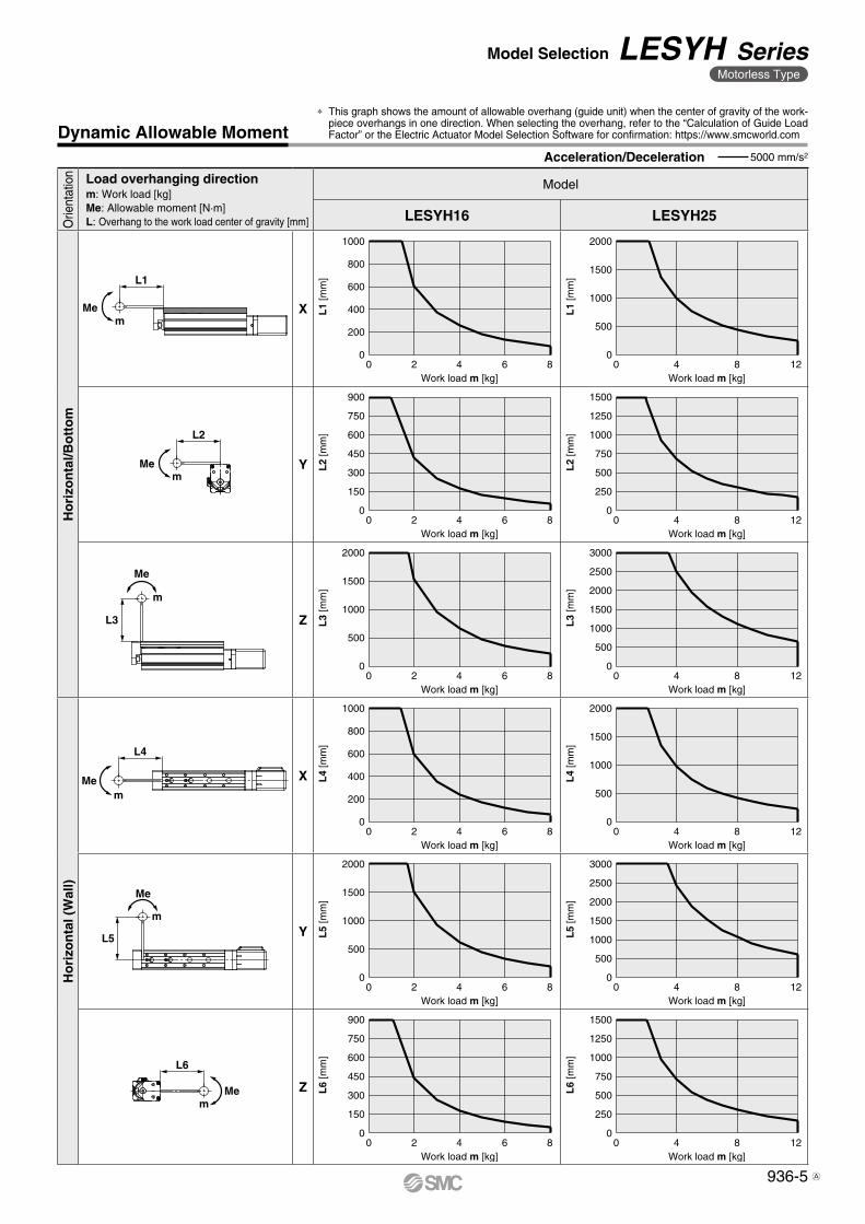
Me
m
L3
Mem
L1
m
Me
L5
mMe
L4
mMe
L2
mMe
L6
Dynamic Allowable MomentAcceleration/Deceleration 5000 mm/s2
Orie
ntat
ion Load overhanging direction
m: Work load [kg]Me: Allowable moment [N·m]L: Overhang to the work load center of gravity [mm]
Model
LESYH16 LESYH25
Ho
rizo
nta
l/Bo
tto
m
X
Y
Z
Ho
rizo
nta
l (W
all)
X
Y
Z
* This graph shows the amount of allowable overhang (guide unit) when the center of gravity of the work-piece overhangs in one direction. When selecting the overhang, refer to the “Calculation of Guide Load Factor” or the Electric Actuator Model Selection Software for confirmation: https://www.smcworld.com
0
500
1000
1500
2000
2500
3000
0
500
1000
1500
2000
0
500
1000
1500
2000
0 4 8 12
0
250
500
750
1000
1250
1500
0 4 8 12
0 4 8 12
Work load m [kg]
L1
[mm
]
Work load m [kg]
L2
[mm
]
0
250
500
750
1000
1250
1500
0 4 8 12Work load m [kg]
L6
[mm
]
Work load m [kg]
L3
[mm
]
0 4 8 12Work load m [kg]
L4
[mm
]
0
500
1000
1500
2000
2500
3000
0 4 8 12Work load m [kg]
L5
[mm
]
0
200
400
600
800
1000
0 2 4 6 8
0
500
1000
1500
2000
0
150
300
450
600
750
900
0 2 4 6 8
0 2 4 6 8Work load m [kg]
L3
[mm
]
0
500
1000
1500
2000
0 2 4 6 8Work load m [kg]
L5
[mm
]
Work load m [kg]
L2
[mm
]
0
150
300
450
600
750
900
0 2 4 6 8Work load m [kg]
L6
[mm
]
Work load m [kg]
L1
[mm
]
0
200
400
600
800
1000
0 2 4 6 8Work load m [kg]
L4
[mm
]
936-5
Model Selection LESYH SeriesMotorless Type
A
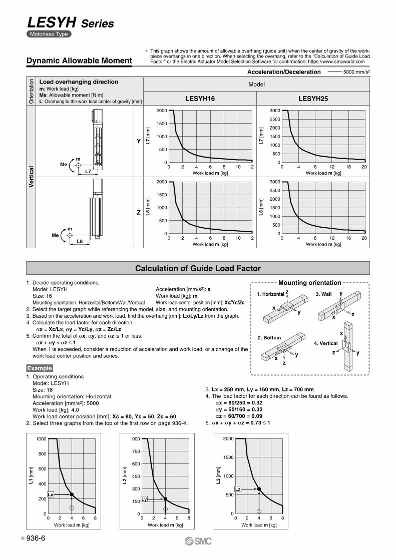
0 2 4 6 8
Work load m [kg]
L1
[mm
]
1000
800
600
400
200
0
Lx
0 2 4 6 8
Work load m [kg]
L2
[mm
]
900
750
600
450
300
150
0
Ly
0 2 4 6 8
Work load m [kg]
L3
[mm
]
2000
1500
1000
500
0
Lz
Mem
L8
mMe
L7
xy
z
xy
z
x z
y
x
z y
0 2 4 6 8 10 12
Work load m [kg]
L8
[mm
]
Work load m [kg]
L7
[mm
]
2000
1500
1000
500
00 4 8 12 16 20
Work load m [kg]
L8
[mm
]
Work load m [kg]
L7
[mm
]
3000
2500
2000
1500
1000
500
0
0 4 8 12 16 20
3000
2500
2000
1500
1000
500
00 2 4 6 8 10 12
2000
1500
1000
500
0
Dynamic Allowable Moment
Orie
ntat
ion Load overhanging direction
m: Work load [kg]Me: Allowable moment [N·m]L: Overhang to the work load center of gravity [mm]
Model
LESYH16 LESYH25
Ver
tica
l
Y
Z
* This graph shows the amount of allowable overhang (guide unit) when the center of gravity of the work-piece overhangs in one direction. When selecting the overhang, refer to the “Calculation of Guide Load Factor” or the Electric Actuator Model Selection Software for confirmation: https://www.smcworld.com
Acceleration/Deceleration 5000 mm/s2
Calculation of Guide Load Factor
1. Operating conditionsModel: LESYHSize: 16Mounting orientation: HorizontalAcceleration [mm/s2]: 5000Work load [kg]: 4.0Work load center position [mm]: Xc = 80, Yc = 50, Zc = 60
2. Select three graphs from the top of the first row on page 936-4.
Example
Acceleration [mm/s2]: aWork load [kg]: mWork load center position [mm]: Xc/Yc/Zc
Mounting orientation
1. Horizontal 3. Wall
2. Bottom4. Vertical
1. Decide operating conditions.Model: LESYHSize: 16Mounting orientation: Horizontal/Bottom/Wall/Vertical
2. Select the target graph while referencing the model, size, and mounting orientation.3. Based on the acceleration and work load, find the overhang [mm]: Lx/Ly/Lz from the graph.4. Calculate the load factor for each direction.
αx = Xc/Lx, αy = Yc/Ly, αz = Zc/Lz5. Confirm the total of αx, αy, and αz is 1 or less.
αx + αy + αz ≤ 1When 1 is exceeded, consider a reduction of acceleration and work load, or a change of the work load center position and series.
3. Lx = 250 mm, Ly = 160 mm, Lz = 700 mm4. The load factor for each direction can be found as follows.
αx = 80/250 = 0.32αy = 50/160 = 0.32αz = 60/700 = 0.09
5. αx + αy + αz = 0.73 ≤ 1
936-6
LESYH SeriesMotorless Type
A
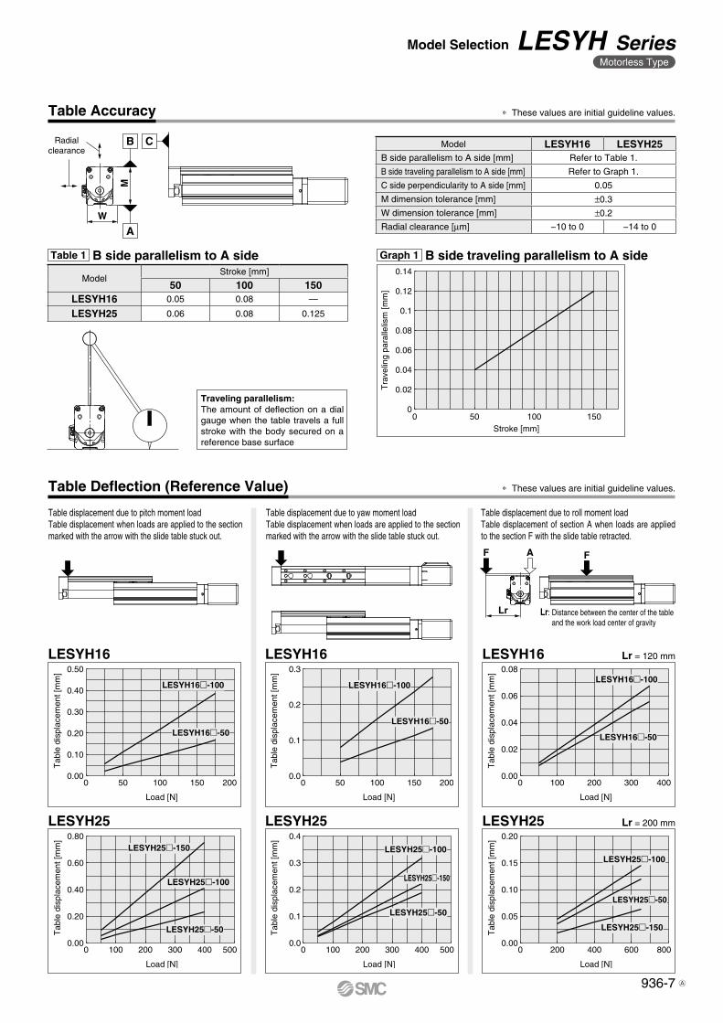
Radialclearance
CB
AW
M
0.14
0.12
0.1
0.08
0.06
0.04
0.02
00 50 100 150
Stroke [mm]
Tra
velin
g pa
ralle
lism
[mm
]
F
Lr: Distance between the center of the table and the work load center of gravity
AF
Lr
Load [N]
Tab
le d
ispl
acem
ent [
mm
] 0.50
0.40
0.30
0.20
0.10
0.000 50 100 150 200
LESYH16�-100
LESYH16�-50
Load [N]
Tab
le d
ispl
acem
ent [
mm
] 0.3
0.2
0.1
0.00 50 100 150 200
LESYH16�-100
LESYH16�-50
Load [N]
Tab
le d
ispl
acem
ent [
mm
] 0.08
0.06
0.04
0.02
0.000 100 200 300 400
LESYH16�-100
LESYH16�-50
Load [N]
Tab
le d
ispl
acem
ent [
mm
] 0.80
0.60
0.40
0.20
0.000 100 200 300 400 500
LESYH25�-150
LESYH25�-100
LESYH25�-50
Load [N]
Tab
le d
ispl
acem
ent [
mm
] 0.4
0.3
0.2
0.1
0.00 100 200 300 400 500
LESYH25�-100
LESYH25�-150
LESYH25�-50
Load [N]
Tab
le d
ispl
acem
ent [
mm
] 0.20
0.15
0.10
0.05
0.000 200 400 600 800
LESYH25�-100
LESYH25�-50
LESYH25�-150
Table Accuracy
Table 1 B side parallelism to A side Graph 1 B side traveling parallelism to A side
* These values are initial guideline values.
Traveling parallelism:The amount of deflection on a dial gauge when the table travels a full stroke with the body secured on a reference base surface
ModelStroke [mm]
50 100 150LESYH16 0.05 0.08 —
LESYH25 0.06 0.08 0.125
Model LESYH16 LESYH25B side parallelism to A side [mm] Refer to Table 1.
B side traveling parallelism to A side [mm] Refer to Graph 1.
C side perpendicularity to A side [mm] 0.05
M dimension tolerance [mm] ±0.3
W dimension tolerance [mm] ±0.2
Radial clearance [μm] −10 to 0 −14 to 0
LESYH16 LESYH16 Lr = 120 mmLESYH16
Table Deflection (Reference Value) * These values are initial guideline values.
Table displacement due to yaw moment loadTable displacement when loads are applied to the section marked with the arrow with the slide table stuck out.
Table displacement due to roll moment loadTable displacement of section A when loads are applied to the section F with the slide table retracted.
Table displacement due to pitch moment load Table displacement when loads are applied to the section marked with the arrow with the slide table stuck out.
LESYH25 LESYH25 Lr = 200 mmLESYH25
936-7
Model Selection LESYH SeriesMotorless Type
A
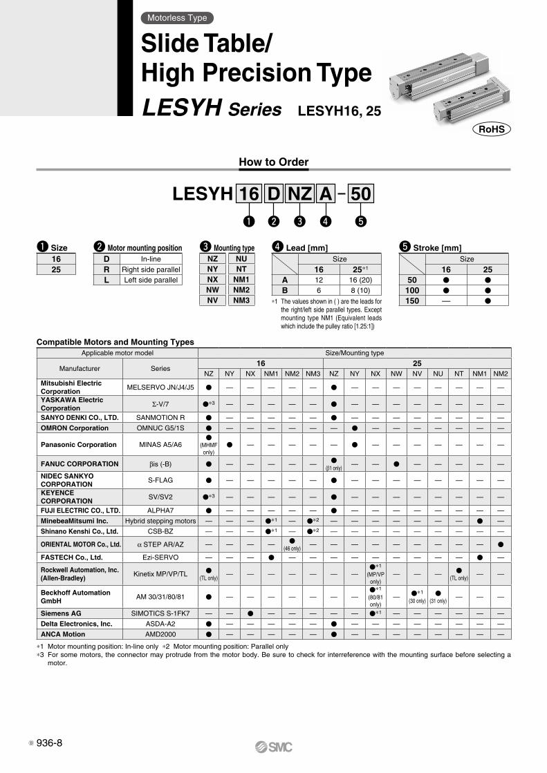
How to Order
w re tq
Motorless Type
Slide Table/High Precision TypeLESYH Series LESYH16, 25
*1 The values shown in ( ) are the leads for the right/left side parallel types. Except mounting type NM1 (Equivalent leads which include the pulley ratio [1.25:1])
r Lead [mm]Size
16 25*1
A 12 16 (20)
B 6 8 (10)
Compatible Motors and Mounting Types
w Motor mounting positionD In-line
R Right side parallel
L Left side parallel
q Size1625
t Stroke [mm]Size
16 2550 V V
100 V V
150 — V
LESYH 16 D NZ A 50
e Mounting typeNZ NUNY NTNX NM1NW NM2NV NM3
Applicable motor model Size/Mounting type
Manufacturer Series16 25
NZ NY NX NM1 NM2 NM3 NZ NY NX NW NV NU NT NM1 NM2Mitsubishi Electric Corporation
MELSERVO JN/J4/J5 V — — — — — V — — — — — — — —
YASKAWA Electric Corporation Σ-V/7 V*3 — — — — — V — — — — — — — —
SANYO DENKI CO., LTD. SANMOTION R V — — — — — V — — — — — — — —
OMRON Corporation OMNUC G5/1S V — — — — — — V — — — — — — —
Panasonic Corporation MINAS A5/A6V
(MHMF only)
V — — — — — V — — — — — — —
FANUC CORPORATION βis (-B) V — — — — — V(β1 only)
— — V — — — — —
NIDEC SANKYO CORPORATION
S-FLAG V — — — — — V — — — — — — — —
KEYENCE CORPORATION
SV/SV2 V*3 — — — — — V — — — — — — — —
FUJI ELECTRIC CO., LTD. ALPHA7 V — — — — — V — — — — — — — —
MinebeaMitsumi Inc. Hybrid stepping motors — — — V*1 — V*2 — — — — — — — V —
Shinano Kenshi Co., Ltd. CSB-BZ — — — V*1 — V*2 — — — — — — — — —
ORIENTAL MOTOR Co., Ltd. α STEP AR/AZ — — — — V(46 only)
— — — — — — — — — V
FASTECH Co., Ltd. Ezi-SERVO — — — V — — — — — — — — — V —
Rockwell Automation, Inc.(Allen-Bradley)
Kinetix MP/VP/TL V(TL only)
— — — — — — —V*1
(MP/VP only)
— — — V(TL only)
— —
Beckhoff AutomationGmbH
AM 30/31/80/81 V — — — — — — —V*1
(80/81 only)
— V*1
(30 only)V
(31 only)— — —
Siemens AG SIMOTICS S-1FK7 — — V — — — — — V*1 — — — — — —
Delta Electronics, Inc. ASDA-A2 V — — — — — V — — — — — — — —
ANCA Motion AMD2000 V — — — — — V — — — — — — — —
*1 Motor mounting position: In-line only *2 Motor mounting position: Parallel only*3 For some motors, the connector may protrude from the motor body. Be sure to check for interreference with the mounting surface before selecting a
motor.
936-8B
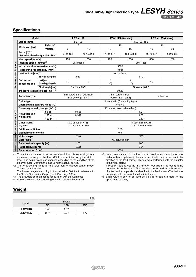
Specifications
Weight
[kg]
ModelStroke
50 100 150LESYH16 1.48 1.87 —
LESYH25 2.77 3.37 4.77
*1 This is the max. value of the horizontal work load. An external guide is necessary to support the load (Friction coefficient of guide: 0.1 or less). The actual work load changes according to the condition of the external guide. Confirm the load using the actual device.
*2 The force setting range for the force control (Speed control mode, Torque control mode)The force changes according to the set value. Set it with reference to the “Force Conversion Graph (Guide)” on page 936-4.
*3 The allowable collision speed for collision with the workpiece*4 A reference value for correcting errors in reciprocal operation
*5 Impact resistance: No malfunction occurred when the actuator was tested with a drop tester in both an axial direction and a perpendicular direction to the lead screw. (The test was performed with the actuator in the initial state.)Vibration resistance: No malfunction occurred in a test ranging between 45 to 2000 Hz. The test was performed in both an axial direction and a perpendicular direction to the lead screw. (The test was performed with the actuator in the initial state.)
*6 Each value is only to be used as a guide to select a motor of the appropriate capacity.
Model LESYH16 LESYH25 (Parallel) LESYH25 (In-line)
Act
uat
or
spec
ifica
tio
ns
Stroke [mm] 50, 100 50, 100, 150
Work load [kg]Horizontal*1 8 12 12Vertical 6 12 10 20 10 20
Force [N]*2
(Set value: Rated torque 45 to 90%)65 to 131 127 to 255 79 to 157 154 to 308 98 to 197 192 to 385
Max. speed [mm/s] 400 200 400 200 400 200Pushing speed [mm/s]*3 35 or less 30 or lessMax. acceleration/deceleration [mm/s2] 5000Positioning repeatability [mm] ±0.01Lost motion [mm]*4 0.1 or less
Ball screw specifications
Thread size [mm] ø10 ø12
Lead [mm](including pulley ratio)
12 616
(20)8
(10)16 8
Shaft length [mm] Stroke + 93.5 Stroke + 104.5Impact/Vibration resistance [m/s2]*5 50/20
Actuation typeBall screw + Belt (Parallel)
Ball screw (In-line)Ball screw + Belt
[Pulley ratio 1.25:1]Ball screw
Guide type Linear guide (Circulating type)Operating temperature range [°C] 5 to 40Operating humidity range [%RH] 90 or less (No condensation)
Oth
er s
peci
ficat
ions
*6
Actuation unit weight [kg]
50 st 0.585 1.21100 st 0.919 1.68150 st — 2.19
Other inertia [kg·cm2]
0.012 (LESYH16)0.015 (LESYH16D)
0.035 (LESYH25)0.061 (LESYH25D)
Friction coefficient 0.05Mechanical efficiency 0.8
Refere
nce mo
tor spe
cificat
ions Motor shape m40 m60
Motor type AC servo motorRated output capacity [W] 100 200Rated torque [N·m] 0.32 0.64Rated rotation [rpm] 3000
936-9
Slide Table/High Precision Type LESYH SeriesMotorless Type
A
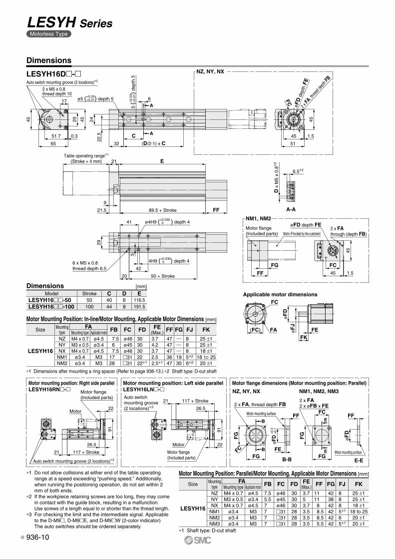
Motor mounting position: Right side parallelLESYH16RN�-�
A-A
Motor mounting position: Left side parallelLESYH16LN�-�
Motor flange dimensions (Motor mounting position: Parallel)
NZ, NY, NX
NM1, NM2
D x
M5
x 0.
8∗2
6.5∗2
A
A
50 + Stroke20
42
29
41 ø4H9 (+0.030 0 ) depth 4
4H9 (+0.030 0 ) depth 4
5
21.5
9
FF
E
(D/2-1) x C32
C
22.5
244529
0.351.7
65
45
Auto switch mounting groove (2 locations)∗3
ø5 (+0.03 +0.01) depth 5
5 (+
0.03
+
0.01
) dep
th 5
617
2 x FA
, threa
d dep
th FB
øFD
dep
th F
E
FC
51
45 1.5
45
89.5 + Stroke
FF
Motor flange(Included parts)
2 x FAthrough (depth FB)
FG1.545
FC
45
øFD depth FE
Motor 22
91
26.5
117 + Stroke21Auto switch mounting groove (2 locations)∗3
91
22Motor
21 117 + Stroke
26.5
Motor flange(Included parts)
Motor flange(Included parts)
Auto switch mounting groove (2 locations)∗3
NZ, NY, NX NM1, NM2, NM3
B
B
E
EFC
FF
FE
øFD
+0.3
+0
.1
FF
Motor mounting surface
B-B E-E
Motor (Provided by the customer)
2 x FA, thread depth FB
Motor mounting surface
2 x FA2 x øFB x FE
øF
D
FG
FG
FC
FG
FG
21
6 x M5 x 0.8thread depth 6.5
Table operating range∗1
(Stroke + 4 mm)
2 x M5 x 0.8thread depth 10
Applicable motor dimensions
øF
DøF
J
FKFEFA
FC
(FC)
Dimensions
*1 Do not allow collisions at either end of the table operating range at a speed exceeding “pushing speed.” Additionally, when running the positioning operation, do not set within 2 mm of both ends.
*2 If the workpiece retaining screws are too long, they may come in contact with the guide block, resulting in a malfunction.Use screws of a length equal to or shorter than the thread length.
*3 For checking the limit and the intermediate signal. Applicable to the D-M9m, D-M9mE, and D-M9mW (2-color indicator)The auto switches should be ordered separately.
LESYH16Dm-m
Dimensions [mm]Model Stroke C D E
LESYH16mm-50 50 40 6 116.5LESYH16mm-100 100 44 8 191.5
Motor Mounting Position: In-line/Motor Mounting, Applicable Motor Dimensions [mm]
Size Mounting type
FA FB FC FD FE(Max.) FF FG FJ FKMounting type Applicable motor
LESYH16
NZ M4 x 0.7 ø4.5 7.5 ø46 30 3.7 47 ― 8 25 ±1NY M3 x 0.5 ø3.4 6 ø45 30 4.2 47 ― 8 25 ±1NX M4 x 0.7 ø4.5 7.5 ø46 30 3.7 47 ― 8 18 ±1
NM1 ø3.4 M3 17 m31 22 2.5 36 19 5*2 18 to 25NM2 ø3.4 M3 28 m31 22*1 2.5*1 47 30 6*2 20 ±1
*1 Dimensions after mounting a ring spacer (Refer to page 936-13.) *2 Shaft type: D-cut shaft
Motor Mounting Position: Parallel/Motor Mounting, Applicable Motor Dimensions [mm]
Size Mounting type
FA FB FC FD FE(Max.) FF FG FJ FKMounting type Applicable motor
LESYH16
NZ M4 x 0.7 ø4.5 7.5 ø46 30 3.7 11 42 8 25 ±1NY M3 x 0.5 ø3.4 5.5 ø45 30 5 11 38 8 25 ±1NX M4 x 0.7 ø4.5 7 ø46 30 3.7 8 42 8 18 ±1
NM1 ø3.4 M3 7 m31 28 3.5 8.5 42 5*1 18 to 25NM2 ø3.4 M3 7 m31 28 3.5 8.5 42 6 20 ±1NM3 ø3.4 M3 7 m31 28 3.5 5.5 42 5*1 20 ±1
*1 Shaft type: D-cut shaft
936-10
LESYH SeriesMotorless Type
B
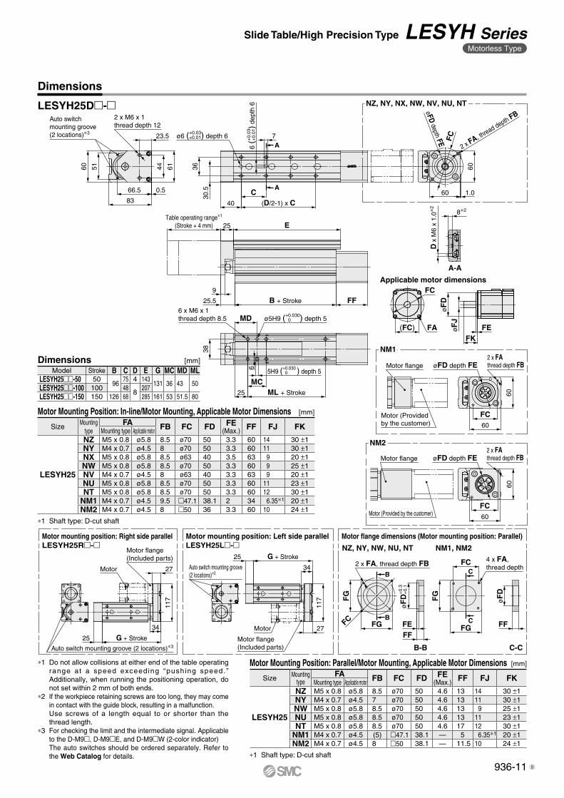
A-A
25.5
D x
M6
x 1.
0∗2
8∗2
A
A
25 ML + Stroke
MC
38
MD ø5H9 (+0.030 0 ) depth 5
6
5H9 (+0.030 0 ) depth 5
FF
E25
9
(D/2-1) x C40
C
30.5
3661
0.5
83
66.5
23.5
Auto switch mounting groove (2 locations)∗3
445160
ø6 (+0.03 +0.01) depth 6 7
60
1.060
FC
øFD depth FE
2 x FA, thread depth FB
6 (+
0.03
+
0.01
) dep
th 6 NZ, NY, NX, NW, NV, NU, NT
NM1
NM2
Motor (Provided by the customer)
Motor flange2 x FAthread depth FB
60
FC
60
øFD depth FE
Motor flange
60
FC60
øFD depth FE2 x FAthread depth FB
Motor 27
117
34
G + Stroke25
27
117
G + Stroke25
34
Motor mounting position: Right side parallelLESYH25R�-�
Motor mounting position: Left side parallelLESYH25L�-�
Motor flange dimensions (Motor mounting position: Parallel)
NZ, NY, NW, NU, NT NM1, NM2
B C
CB
FG
FC FG
øF
D+
0.3
+0.
1
FFFE
FC
FG
FG
øF
D
FF
Auto switch mounting groove (2 locations)∗3
Auto switch mounting groove (2 locations)∗3
Motor (Provided by the customer)
B-B C-C
2 x FA, thread depth FBMotor
Table operating range∗1
(Stroke + 4 mm)
Motor flange(Included parts)
6 x M6 x 1thread depth 8.5
Motor flange(Included parts)
B + Stroke
2 x M6 x 1thread depth 12
4 x FA,thread depth
FKFEø
FJ
øF
D
FC
FA(FC)
Applicable motor dimensions
Dimensions
*1 Do not allow collisions at either end of the table operating range at a speed exceeding “pushing speed.” Additionally, when running the positioning operation, do not set within 2 mm of both ends.
*2 If the workpiece retaining screws are too long, they may come in contact with the guide block, resulting in a malfunction.Use screws of a length equal to or shorter than the thread length.
*3 For checking the limit and the intermediate signal. Applicable to the D-M9m, D-M9mE, and D-M9mW (2-color indicator)The auto switches should be ordered separately. Refer to the Web Catalog for details.
LESYH25Dm-m
Dimensions [mm]Model Stroke B C D E G MC MD ML
LESYH25□□-50 5096
75 4 143131 36 43 50LESYH25□□-100 100 48
8207
LESYH25□□-150 150 126 68 285 161 53 51.5 80
Motor Mounting Position: In-line/Motor Mounting, Applicable Motor Dimensions [mm]
SizeMounting
typeFA FB FC FD FE
(Max.) FF FJ FKMounting type Applicable motor
LESYH25
NZ M5 x 0.8 ø5.8 8.5 ø70 50 3.3 60 14 30 ±1NY M4 x 0.7 ø4.5 8 ø70 50 3.3 60 11 30 ±1NX M5 x 0.8 ø5.8 8.5 ø63 40 3.5 63 9 20 ±1NW M5 x 0.8 ø5.8 8.5 ø70 50 3.3 60 9 25 ±1NV M4 x 0.7 ø4.5 8 ø63 40 3.3 63 9 20 ±1NU M5 x 0.8 ø5.8 8.5 ø70 50 3.3 60 11 23 ±1NT M5 x 0.8 ø5.8 8.5 ø70 50 3.3 60 12 30 ±1
NM1 M4 x 0.7 ø4.5 9.5 m47.1 38.1 2 34 6.35*1 20 ±1NM2 M4 x 0.7 ø4.5 8 m50 36 3.3 60 10 24 ±1
*1 Shaft type: D-cut shaft
Motor Mounting Position: Parallel/Motor Mounting, Applicable Motor Dimensions [mm]
Size Mounting type
FA FB FC FD FE(Max.) FF FJ FKMounting type Applicable motor
LESYH25
NZ M5 x 0.8 ø5.8 8.5 ø70 50 4.6 13 14 30 ±1NY M4 x 0.7 ø4.5 7 ø70 50 4.6 13 11 30 ±1NW M5 x 0.8 ø5.8 8.5 ø70 50 4.6 13 9 25 ±1NU M5 x 0.8 ø5.8 8.5 ø70 50 4.6 13 11 23 ±1NT M5 x 0.8 ø5.8 8.5 ø70 50 4.6 17 12 30 ±1
NM1 M4 x 0.7 ø4.5 (5) m47.1 38.1 — 5 6.35*1 20 ±1NM2 M4 x 0.7 ø4.5 8 m50 38.1 — 11.5 10 24 ±1
*1 Shaft type: D-cut shaft
936-11
Slide Table/High Precision Type LESYH SeriesMotorless Type
B
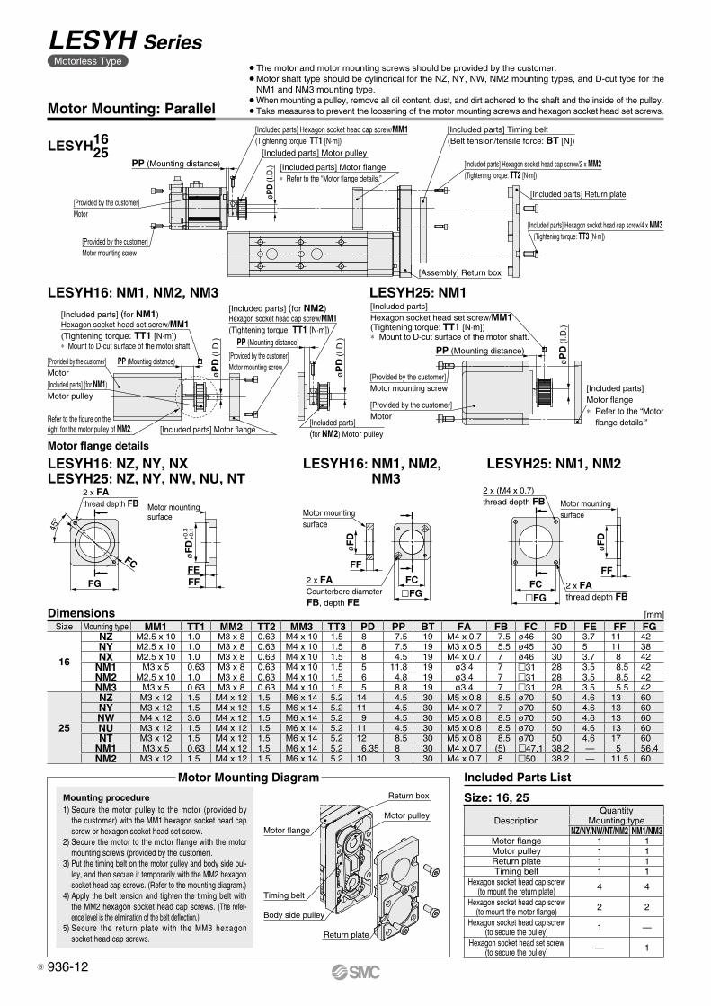
[Provided by the customer]Motor mounting screw
[Provided by the customer]Motor
[Included parts] Motor pulley
[Included parts] Hexagon socket head cap screw/MM1(Tightening torque: TT1 [N·m])
øPD
(I.D
.) [Included parts] Hexagon socket head cap screw/2 x MM2(Tightening torque: TT2 [N·m])
[Included parts] Timing belt(Belt tension/tensile force: BT [N])
[Assembly] Return box
[Included parts] Hexagon socket head cap screw/4 x MM3 (Tightening torque: TT3 [N·m])
[Included parts] Motor flange∗ Refer to the “Motor flange details.”
[Included parts] Return plate
PP (Mounting distance)
[Provided by the customer]Motor[Included parts] (for NM1)Motor pulley
Refer to the figure on the right for the motor pulley of NM2. [Included parts] Motor flange
[Included parts](for NM2) Motor pulley
øP
D (
I.D.)
PP (Mounting distance)
øP
D (
I.D.)PP (Mounting distance)
[Provided by the customer]Motor mounting screw
[Included parts] (for NM2)Hexagon socket head cap screw/MM1(Tightening torque: TT1 [N·m])
[Included parts] (for NM1)Hexagon socket head set screw/MM1(Tightening torque: TT1 [N·m])∗ Mount to D-cut surface of the motor shaft.
[Included parts] Motor flange∗ Refer to the “Motor
flange details.”
[Provided by the customer]Motor
øP
D (
I.D.)
[Included parts] Hexagon socket head set screw/MM1(Tightening torque: TT1 [N·m])∗ Mount to D-cut surface of the motor shaft.
[Provided by the customer]Motor mounting screw
PP (Mounting distance)
Motor flange
Timing belt
Return box
Motor pulley
Body side pulley
Return plate
Motor Mounting: Parallel
Motor flange details
LESYH25: NM1, NM2LESYH16: NM1, NM2, NM3
LESYH16: NZ, NY, NXLESYH25: NZ, NY, NW, NU, NT
LESYH1625
LESYH16: NM1, NM2, NM3 LESYH25: NM1
[mm]Size Mounting type MM1 TT1 MM2 TT2 MM3 TT3 PD PP BT FA FB FC FD FE FF FG
16
NZ M2.5 x 10 1.0 M3 x 8 0.63 M4 x 10 1.5 8 7.5 19 M4 x 0.7 7.5 ø46 30 3.7 11 42NY M2.5 x 10 1.0 M3 x 8 0.63 M4 x 10 1.5 8 7.5 19 M3 x 0.5 5.5 ø45 30 5 11 38NX M2.5 x 10 1.0 M3 x 8 0.63 M4 x 10 1.5 8 4.5 19 M4 x 0.7 7 ø46 30 3.7 8 42
NM1 M3 x 5 0.63 M3 x 8 0.63 M4 x 10 1.5 5 11.8 19 ø3.4 7 m31 28 3.5 8.5 42NM2 M2.5 x 10 1.0 M3 x 8 0.63 M4 x 10 1.5 6 4.8 19 ø3.4 7 m31 28 3.5 8.5 42NM3 M3 x 5 0.63 M3 x 8 0.63 M4 x 10 1.5 5 8.8 19 ø3.4 7 m31 28 3.5 5.5 42
25
NZ M3 x 12 1.5 M4 x 12 1.5 M6 x 14 5.2 14 4.5 30 M5 x 0.8 8.5 ø70 50 4.6 13 60NY M3 x 12 1.5 M4 x 12 1.5 M6 x 14 5.2 11 4.5 30 M4 x 0.7 7 ø70 50 4.6 13 60NW M4 x 12 3.6 M4 x 12 1.5 M6 x 14 5.2 9 4.5 30 M5 x 0.8 8.5 ø70 50 4.6 13 60NU M3 x 12 1.5 M4 x 12 1.5 M6 x 14 5.2 11 4.5 30 M5 x 0.8 8.5 ø70 50 4.6 13 60NT M3 x 12 1.5 M4 x 12 1.5 M6 x 14 5.2 12 8.5 30 M5 x 0.8 8.5 ø70 50 4.6 17 60
NM1 M3 x 5 0.63 M4 x 12 1.5 M6 x 14 5.2 6.35 8 30 M4 x 0.7 (5) m47.1 38.2 — 5 56.4NM2 M3 x 12 1.5 M4 x 12 1.5 M6 x 14 5.2 10 3 30 M4 x 0.7 8 m50 38.2 — 11.5 60
Dimensions�FGFC
FF
øF
D
2 x FAthread depth FB
2 x (M4 x 0.7)thread depth FB Motor mounting
surface
FF
øF
D
FC�FG
Motor mounting surface
2 x FACounterbore diameter FB, depth FE
45°
FC
FG FFFE
øF
D+
0.3
+0.
1
2 x FAthread depth FB Motor mounting
surface
Mounting procedure1) Secure the motor pulley to the motor (provided by
the customer) with the MM1 hexagon socket head cap screw or hexagon socket head set screw.
2) Secure the motor to the motor flange with the motor mounting screws (provided by the customer).
3) Put the timing belt on the motor pulley and body side pul-ley, and then secure it temporarily with the MM2 hexagon socket head cap screws. (Refer to the mounting diagram.)
4) Apply the belt tension and tighten the timing belt with the MM2 hexagon socket head cap screws. (The refer-ence level is the elimination of the belt deflection.)
5) Secure the return plate with the MM3 hexagon socket head cap screws.
¡The motor and motor mounting screws should be provided by the customer.¡Motor shaft type should be cylindrical for the NZ, NY, NW, NM2 mounting types, and D-cut type for the
NM1 and NM3 mounting type.¡When mounting a pulley, remove all oil content, dust, and dirt adhered to the shaft and the inside of the pulley.¡Take measures to prevent the loosening of the motor mounting screws and hexagon socket head set screws.
Size: 16, 25
Motor Mounting Diagram
DescriptionQuantity
Mounting typeNZ/NY/NW/NT/NM2 NM1/NM3
Motor flange 1 1Motor pulley 1 1Return plate 1 1Timing belt 1 1
Hexagon socket head cap screw(to mount the return plate) 4 4
Hexagon socket head cap screw(to mount the motor flange) 2 2
Hexagon socket head cap screw(to secure the pulley) 1 —
Hexagon socket head set screw(to secure the pulley) — 1
Included Parts List
936-12
LESYH SeriesMotorless Type
B
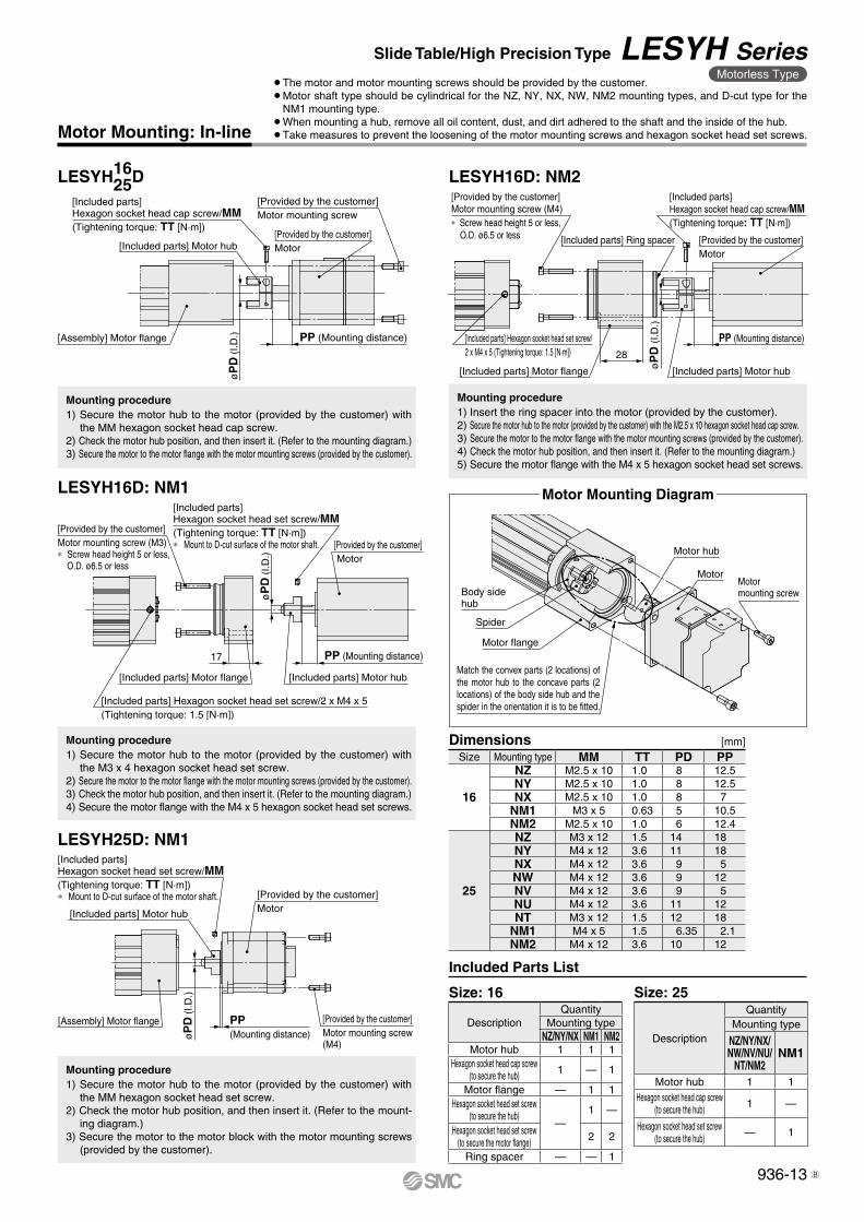
[Provided by the customer]Motor mounting screw (M4)∗ Screw head height 5 or less,
O.D. ø6.5 or less [Included parts] Ring spacer
[Included parts] Hexagon socket head cap screw/MM(Tightening torque: TT [N·m])
[Provided by the customer]Motor
PP (Mounting distance)
[Included parts] Motor hubøP
D (I
.D.)
28
[Included parts] Motor flange
[Included parts] Hexagon socket head set screw/2 x M4 x 5 (Tightening torque: 1.5 [N·m])
[Included parts] Hexagon socket head cap screw/MM(Tightening torque: TT [N·m])
[Included parts] Motor hub[Provided by the customer]Motor
[Provided by the customer]Motor mounting screw
PP (Mounting distance)
øP
D (
I.D.)[Assembly] Motor flange
Motor hub
MotorMotor mounting screwBody side
hub
Spider
Motor flange
Match the convex parts (2 locations) of the motor hub to the concave parts (2 locations) of the body side hub and the spider in the orientation it is to be fitted.
[Assembly] Motor flange
[Included parts] Hexagon socket head set screw/MM(Tightening torque: TT [N·m])∗ Mount to D-cut surface of the motor shaft.
[Included parts] Motor hub
[Provided by the customer]Motor
[Provided by the customer]Motor mounting screw(M4)
PP (Mounting distance)ø
PD
(I.D
.)
17
øP
D (
I.D.)
[Included parts] Motor flange
[Included parts] Hexagon socket head set screw/2 x M4 x 5(Tightening torque: 1.5 [N·m])
[Provided by the customer]Motor mounting screw (M3)∗ Screw head height 5 or less,
O.D. ø6.5 or less
[Included parts] Hexagon socket head set screw/MM(Tightening torque: TT [N·m])∗ Mount to D-cut surface of the motor shaft.
[Included parts] Motor hub
[Provided by the customer] Motor
PP (Mounting distance)
Mounting procedure1) Insert the ring spacer into the motor (provided by the customer).2) Secure the motor hub to the motor (provided by the customer) with the M2.5 x 10 hexagon socket head cap screw.3) Secure the motor to the motor flange with the motor mounting screws (provided by the customer).4) Check the motor hub position, and then insert it. (Refer to the mounting diagram.)5) Secure the motor flange with the M4 x 5 hexagon socket head set screws.
Size: 25
Description
QuantityMounting type
NZ/NY/NX/NW/NV/NU/
NT/NM2NM1
Motor hub 1 1Hexagon socket head cap screw
(to secure the hub) 1 —
Hexagon socket head set screw(to secure the hub) — 1
Size Mounting type MM TT PD PP
16
NZ M2.5 x 10 1.0 8 12.5NY M2.5 x 10 1.0 8 12.5NX M2.5 x 10 1.0 8 7
NM1 M3 x 5 0.63 5 10.5NM2 M2.5 x 10 1.0 6 12.4
25
NZ M3 x 12 1.5 14 18NY M4 x 12 3.6 11 18NX M4 x 12 3.6 9 5NW M4 x 12 3.6 9 12NV M4 x 12 3.6 9 5NU M4 x 12 3.6 11 12NT M3 x 12 1.5 12 18
NM1 M4 x 5 1.5 6.35 2.1NM2 M4 x 12 3.6 10 12
[mm]Dimensions
Motor Mounting: In-line
Mounting procedure1) Secure the motor hub to the motor (provided by the customer) with
the MM hexagon socket head cap screw.2) Check the motor hub position, and then insert it. (Refer to the mounting diagram.)3) Secure the motor to the motor flange with the motor mounting screws (provided by the customer).
Mounting procedure1) Secure the motor hub to the motor (provided by the customer) with
the M3 x 4 hexagon socket head set screw.2) Secure the motor to the motor flange with the motor mounting screws (provided by the customer).3) Check the motor hub position, and then insert it. (Refer to the mounting diagram.)4) Secure the motor flange with the M4 x 5 hexagon socket head set screws.
Mounting procedure1) Secure the motor hub to the motor (provided by the customer) with
the MM hexagon socket head set screw.2) Check the motor hub position, and then insert it. (Refer to the mount-
ing diagram.)3) Secure the motor to the motor block with the motor mounting screws
(provided by the customer).
DescriptionQuantity
Mounting typeNZ/NY/NX NM1 NM2
Motor hub 1 1 1Hexagon socket head cap screw
(to secure the hub) 1 — 1
Motor flange — 1 1Hexagon socket head set screw
(to secure the hub)—
1 —
Hexagon socket head set screw(to secure the motor flange) 2 2
Ring spacer — — 1
Size: 16
Included Parts List
¡The motor and motor mounting screws should be provided by the customer.¡Motor shaft type should be cylindrical for the NZ, NY, NX, NW, NM2 mounting types, and D-cut type for the
NM1 mounting type.¡When mounting a hub, remove all oil content, dust, and dirt adhered to the shaft and the inside of the hub.¡Take measures to prevent the loosening of the motor mounting screws and hexagon socket head set screws.
Motor Mounting Diagram
LESYH1625D LESYH16D: NM2
LESYH16D: NM1
LESYH25D: NM1
936-13
Slide Table/High Precision Type LESYH SeriesMotorless Type
B
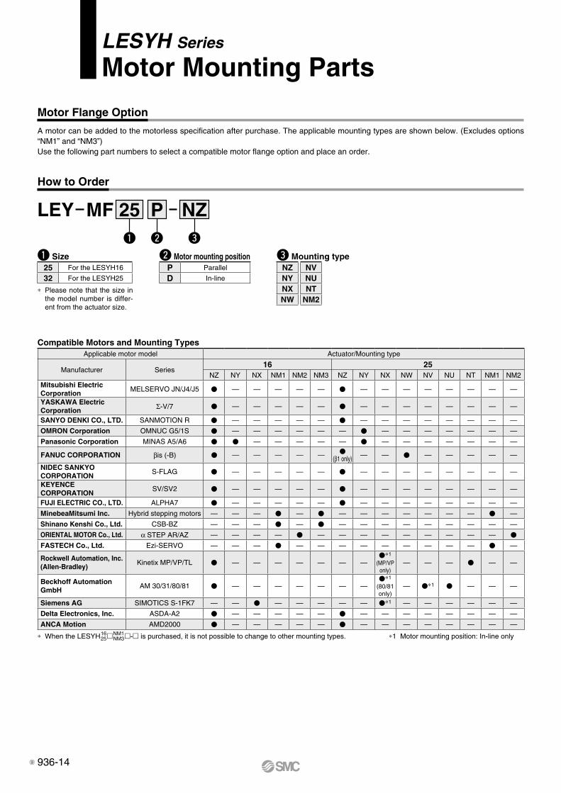
q Size
LEY MF NZ25 Pq w e
25 For the LESYH16
32 For the LESYH25
* Please note that the size in the model number is differ-ent from the actuator size.
w Motor mounting positionP Parallel
D In-line
LESYH Series
Motor Mounting Parts
Motor Flange Option
A motor can be added to the motorless specification after purchase. The applicable mounting types are shown below. (Excludes options “NM1” and “NM3”) Use the following part numbers to select a compatible motor flange option and place an order.
How to Order
e Mounting type
* When the LESYH1625mNM1
NM3m-m is purchased, it is not possible to change to other mounting types. *1 Motor mounting position: In-line only
NZNYNXNW
NVNUNT
NM2
Compatible Motors and Mounting TypesApplicable motor model Actuator/Mounting type
Manufacturer Series16 25
NZ NY NX NM1 NM2 NM3 NZ NY NX NW NV NU NT NM1 NM2Mitsubishi ElectricCorporation
MELSERVO JN/J4/J5 V — — — — — V — — — — — — — —
YASKAWA Electric Corporation Σ-V/7 V — — — — — V — — — — — — — —
SANYO DENKI CO., LTD. SANMOTION R V — — — — — V — — — — — — — —
OMRON Corporation OMNUC G5/1S V — — — — — — V — — — — — — —
Panasonic Corporation MINAS A5/A6 V V — — — — — V — — — — — — —
FANUC CORPORATION βis (-B) V — — — — — V(β1 only) — — V — — — — —
NIDEC SANKYO CORPORATION
S-FLAG V — — — — — V — — — — — — — —
KEYENCE CORPORATION
SV/SV2 V — — — — — V — — — — — — — —
FUJI ELECTRIC CO., LTD. ALPHA7 V — — — — — V — — — — — — — —
MinebeaMitsumi Inc. Hybrid stepping motors — — — V — V — — — — — — — V —
Shinano Kenshi Co., Ltd. CSB-BZ — — — V — V — — — — — — — — —
ORIENTAL MOTOR Co., Ltd. α STEP AR/AZ — — — — V — — — — — — — — — V
FASTECH Co., Ltd. Ezi-SERVO — — — V — — — — — — — — — V —
Rockwell Automation, Inc. (Allen-Bradley)
Kinetix MP/VP/TL V — — — — — — —V*1
(MP/VP only)
— — — V — —
Beckhoff AutomationGmbH
AM 30/31/80/81 V — — — — — — —V*1
(80/81 only)
— V*1 V — — —
Siemens AG SIMOTICS S-1FK7 — — V — — — — — V*1 — — — — — —
Delta Electronics, Inc. ASDA-A2 V — — — — — V — — — — — — — —
ANCA Motion AMD2000 V — — — — — V — — — — — — — —
936-14B
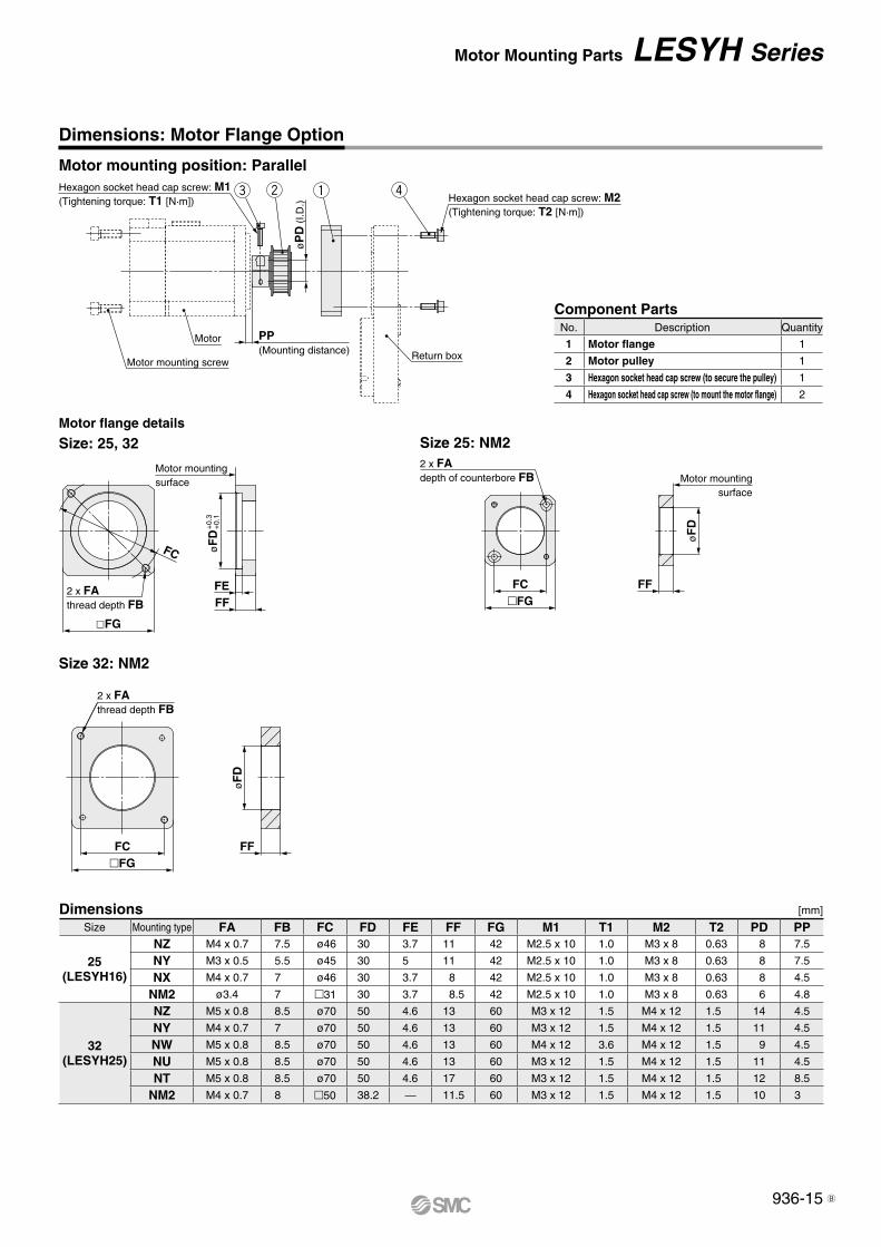
2 x FAdepth of counterbore FB Motor mounting
surface
øF
D
FFFC�FG
øF
D
FF�FGFC
2 x FAthread depth FB
Motor mounting screw
Motor
Hexagon socket head cap screw: M1(Tightening torque: T1 [N·m])
Return box
PP (Mounting distance)
øP
D (
I.D.)
qwe r Hexagon socket head cap screw: M2(Tightening torque: T2 [N·m])
2 x FAthread depth FB
FC øF
D
FFFE
�FG
Motor mountingsurface
+0.
3+
0.1
Size 25: NM2
Dimensions: Motor Flange Option
Motor mounting position: Parallel
Dimensions [mm]
Motor flange details
Size: 25, 32
Component PartsNo. Description Quantity
1 Motor flange 1
2 Motor pulley 1
3 Hexagon socket head cap screw (to secure the pulley) 1
4 Hexagon socket head cap screw (to mount the motor flange) 2
Size Mounting type FA FB FC FD FE FF FG M1 T1 M2 T2 PD PP
25(LESYH16)
NZ M4 x 0.7 7.5 ø46 30 3.7 11 42 M2.5 x 10 1.0 M3 x 8 0.63 8 7.5
NY M3 x 0.5 5.5 ø45 30 5 11 42 M2.5 x 10 1.0 M3 x 8 0.63 8 7.5
NX M4 x 0.7 7 ø46 30 3.7 8 42 M2.5 x 10 1.0 M3 x 8 0.63 8 4.5
NM2 ø3.4 7 m31 30 3.7 8.5 42 M2.5 x 10 1.0 M3 x 8 0.63 6 4.8
32(LESYH25)
NZ M5 x 0.8 8.5 ø70 50 4.6 13 60 M3 x 12 1.5 M4 x 12 1.5 14 4.5
NY M4 x 0.7 7 ø70 50 4.6 13 60 M3 x 12 1.5 M4 x 12 1.5 11 4.5
NW M5 x 0.8 8.5 ø70 50 4.6 13 60 M4 x 12 3.6 M4 x 12 1.5 9 4.5
NU M5 x 0.8 8.5 ø70 50 4.6 13 60 M3 x 12 1.5 M4 x 12 1.5 11 4.5
NT M5 x 0.8 8.5 ø70 50 4.6 17 60 M3 x 12 1.5 M4 x 12 1.5 12 8.5
NM2 M4 x 0.7 8 m50 38.2 — 11.5 60 M3 x 12 1.5 M4 x 12 1.5 10 3
Size 32: NM2
936-15
Motor Mounting Parts LESYH Series
B
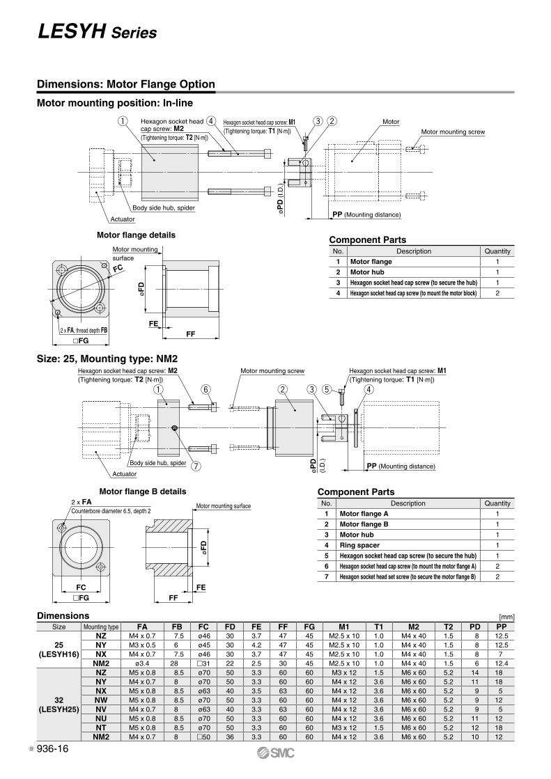
�FGFC
2 x FACounterbore diameter 6.5, depth 2
Motor mounting surface
øF
D
FEFF
y w re tq
u
Hexagon socket head cap screw: M2(Tightening torque: T2 [N·m])
Motor mounting screw Hexagon socket head cap screw: M1(Tightening torque: T1 [N·m])
PP (Mounting distance)Actuator
Body side hub, spider
øP
D(I
.D.)
Hexagon socket head cap screw: M2(Tightening torque: T2 [N·m])
q r Hexagon socket head cap screw: M1(Tightening torque: T1 [N·m])
e w
øP
D (
I.D.)
PP (Mounting distance)Body side hub, spider
Actuator
Motor
Motor mounting screw
2 x FA, thread depth FB�FG
FC
FF
øF
D
Motor mountingsurface
FE
Size: 25, Mounting type: NM2
Motor flange B details Component PartsNo. Description Quantity
1 Motor flange A 1
2 Motor flange B 1
3 Motor hub 1
4 Ring spacer 1
5 Hexagon socket head cap screw (to secure the hub) 1
6 Hexagon socket head cap screw (to mount the motor flange A) 2
7 Hexagon socket head set screw (to secure the motor flange B) 2
Dimensions: Motor Flange Option
Motor mounting position: In-line
Motor flange details Component PartsNo. Description Quantity
1 Motor flange 1
2 Motor hub 1
3 Hexagon socket head cap screw (to secure the hub) 1
4 Hexagon socket head cap screw (to mount the motor block) 2
Dimensions [mm]Size Mounting type FA FB FC FD FE FF FG M1 T1 M2 T2 PD PP
25(LESYH16)
NZ M4 x 0.7 7.5 ø46 30 3.7 47 45 M2.5 x 10 1.0 M4 x 40 1.5 8 12.5NY M3 x 0.5 6 ø45 30 4.2 47 45 M2.5 x 10 1.0 M4 x 40 1.5 8 12.5NX M4 x 0.7 7.5 ø46 30 3.7 47 45 M2.5 x 10 1.0 M4 x 40 1.5 8 7
NM2 ø3.4 28 m31 22 2.5 30 45 M2.5 x 10 1.0 M4 x 40 1.5 6 12.4
32(LESYH25)
NZ M5 x 0.8 8.5 ø70 50 3.3 60 60 M3 x 12 1.5 M6 x 60 5.2 14 18NY M4 x 0.7 8 ø70 50 3.3 60 60 M4 x 12 3.6 M6 x 60 5.2 11 18NX M5 x 0.8 8.5 ø63 40 3.5 63 60 M4 x 12 3.6 M6 x 60 5.2 9 5NW M5 x 0.8 8.5 ø70 50 3.3 60 60 M4 x 12 3.6 M6 x 60 5.2 9 12NV M4 x 0.7 8 ø63 40 3.3 63 60 M4 x 12 3.6 M6 x 60 5.2 9 5NU M5 x 0.8 8.5 ø70 50 3.3 60 60 M4 x 12 3.6 M6 x 60 5.2 11 12NT M5 x 0.8 8.5 ø70 50 3.3 60 60 M3 x 12 1.5 M6 x 60 5.2 12 18
NM2 M4 x 0.7 8 m50 36 3.3 60 60 M4 x 12 3.6 M6 x 60 5.2 10 12
936-16
LESYH Series
B
Related Documents