ELEC 2200-002 Digital Logic Circuits Fall 2014 Binary Arithmetic (Chapter 1) Vishwani D. Agrawal James J. Danaher Professor Department of Electrical and Computer Engineering Auburn University, Auburn, AL 36849 http://www.eng.auburn.edu/~vagrawal [email protected] Fall 2014, Aug 20 . . . ELEC2200 - 002 Lecture 2 1

Welcome message from author
This document is posted to help you gain knowledge. Please leave a comment to let me know what you think about it! Share it to your friends and learn new things together.
Transcript

ELEC 2200-002Digital Logic Circuits
Fall 2014Binary Arithmetic (Chapter 1)
Vishwani D. AgrawalJames J. Danaher Professor
Department of Electrical and Computer EngineeringAuburn University, Auburn, AL 36849http://www.eng.auburn.edu/~vagrawal
Fall 2014, Aug 20 . . . ELEC2200-002 Lecture 2 1

Fall 2014, Aug 20 . . . ELEC2200-002 Lecture 2 2
Why Binary Arithmetic?
Hardware can only deal with binary digits, 0 and 1.Must represent all numbers, integers or floating point, positive or negative, by binary digits, called bits.Can devise electronic circuits to perform arithmetic operations: add, subtract, multiply and divide, on binary numbers.

Fall 2014, Aug 20 . . . ELEC2200-002 Lecture 2 3
Positive IntegersDecimal system: made of 10 digits, {0,1,2, . . . , 9}
41 = 4×101 + 1×100
255 = 2×10² + 5×101 + 5×100
Binary system: made of two digits, {0,1}00101001 = 0×27 + 0×26 + 1×25 + 0×24
+1×23 + 0×22 + 0×21 + 1×20
= 32 + 8 +1 = 4111111111 = 255, largest number with 8
binary digits, 28-1

Fall 2014, Aug 20 . . . ELEC2200-002 Lecture 2 4
Base or RadixFor decimal system, 10 is called the base or radix.Decimal 41 is also written as 4110 or 41tenBase (radix) for binary system is 2.Thus, 41ten = 1010012 or 101001two
Also, 111ten = 1101111two
and 111two = 7tenWhat about negative numbers?

Fall 2014, Aug 20 . . . ELEC2200-002 Lecture 2 5
Signed Magnitude – What Not to Do
Use fixed length binary representationUse left-most bit (called most significant bit or MSB) for sign:
0 for positive1 for negative
Example: +18ten = 00010010two–18ten = 10010010two

Fall 2014, Aug 20 . . . ELEC2200-002 Lecture 2 6
Difficulties with Signed MagnitudeSign and magnitude bits should be differently treated in arithmetic operations.Addition and subtraction require different logic circuits.Overflow is difficult to detect.“Zero” has two representations:
+ 0ten = 00000000two– 0ten = 10000000two
Signed-integers are not used in modern computers.

Problems with Finite MathFinite size of representation:– Digital circuit cannot be arbitrarily large.– Overflow detection – easy to determine when
the number becomes too large.
Represent negative numbers:– Unique representation of 0.
Fall 2014, Aug 20 . . . ELEC2200-002 Lecture 2 7
-4 0 4 8 12 16 200000 0100 1000 1100 10000 10100
Infiniteuniverseof integers
∞-∞
4-bit numbers
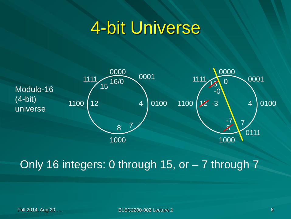
4-bit Universe
Fall 2014, Aug 20 . . . ELEC2200-002 Lecture 2 8
Modulo-16(4-bit)universe
16/0
8
412 0100
1000
1100
0000
151111 0
8
412 0100
1000
1100
0000
-0
111115
-77 7
0111
-3
0001 0001
Only 16 integers: 0 through 15, or – 7 through 7
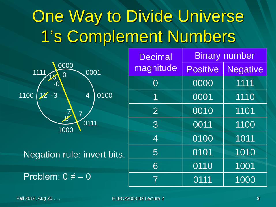
One Way to Divide Universe1’s Complement Numbers
Fall 2014, Aug 20 . . . ELEC2200-002 Lecture 2 9
0
8
412 0100
1000
1100
0000
-0
111115
-7 70111
-3
0001
Decimal magnitude
Binary numberPositive Negative
0 0000 11111 0001 11102 0010 11013 0011 11004 0100 10115 0101 10106 0110 10017 0111 1000
Negation rule: invert bits.
Problem: 0 ≠ – 0

Another Way to Divide Universe2’s Complement Numbers
Fall 2014, Aug 20 . . . ELEC2200-002 Lecture 2 10
0
8
412 0100
1000
1100
0000
-1
111115
-8 70111
-4
0001
Decimal magnitude
Binary numberPositive Negative
0 00001 0001 11112 0010 11103 0011 11014 0100 11005 0101 10116 0110 10107 0111 10018 1000
Negation rule: invert bitsand add 1
Subtract 1on this side
Fall 2014, Aug 20 . . . ELEC2200-002 Lecture 2 11
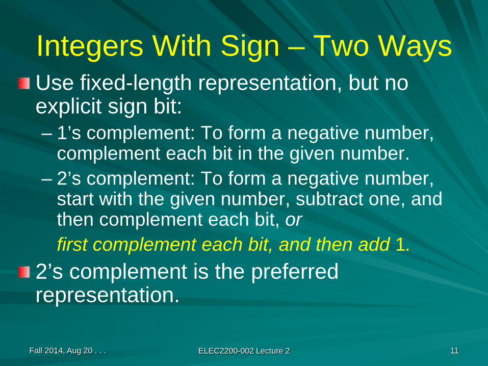
Integers With Sign – Two WaysUse fixed-length representation, but no explicit sign bit:– 1’s complement: To form a negative number,
complement each bit in the given number.– 2’s complement: To form a negative number,
start with the given number, subtract one, and then complement each bit, orfirst complement each bit, and then add 1.
2’s complement is the preferred representation.
Fall 2014, Aug 20 . . . ELEC2200-002 Lecture 2 12
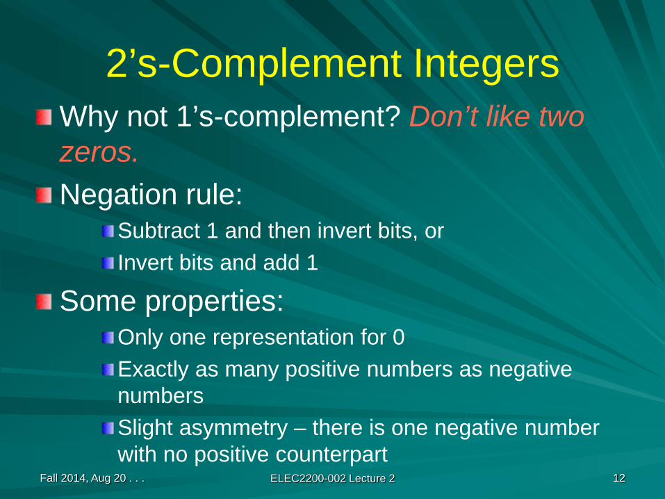
2’s-Complement IntegersWhy not 1’s-complement? Don’t like two zeros.Negation rule:
Subtract 1 and then invert bits, orInvert bits and add 1
Some properties:Only one representation for 0Exactly as many positive numbers as negative numbersSlight asymmetry – there is one negative number with no positive counterpart

General Method for Binary Integers with Sign
Select number (n) of bits in representation.Partition 2n integers into two sets:
00…0 through 01…1 are 2n/2 positive integers.10…0 through 11…1 are 2n/2 negative integers.
Negation rule transforms negative to positive, and vice-versa:
Signed magnitude: invert MSB (most significant bit)1’s complement: Subtract from 2n – 1 or 1…1 (same as “inverting all bits”)2’s complement: Subtract from 2n or 10…0 (same as 1’s complement + 1)
Fall 2014, Aug 20 . . . ELEC2200-002 Lecture 2 13
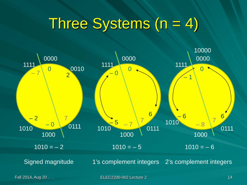
Three Systems (n = 4)
Fall 2014, Aug 20 . . . ELEC2200-002 Lecture 2 14
0000
10000111
1111
1010 = – 2
Signed magnitude
0000
1000
1111
1010 = – 5
1’s complement integers
0010
1010 1010 0111
2
– 26
– 5
0000
1000
1111
10000
1010 = – 6
2’s complement integers
10100111
6– 6
0– 0
0
– 7 – 87 7
0
– 07
– 7– 1
Fall 2014, Aug 20 . . . ELEC2200-002 Lecture 2 15
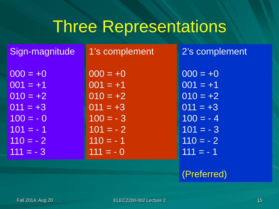
Three RepresentationsSign-magnitude
000 = +0001 = +1010 = +2011 = +3100 = - 0101 = - 1110 = - 2111 = - 3
2’s complement
000 = +0001 = +1010 = +2011 = +3100 = - 4101 = - 3110 = - 2111 = - 1
(Preferred)
1’s complement
000 = +0001 = +1010 = +2011 = +3100 = - 3101 = - 2110 = - 1111 = - 0

Fall 2014, Aug 20 . . . ELEC2200-002 Lecture 2 16
2’s Complement Numbers (n = 3)0
+1
+2
+3
-1
-2
-3
- 4
000
001
010
011
100
101
110
111
additionsubtraction
Negation

Fall 2014, Aug 20 . . . ELEC2200-002 Lecture 2 17
2’s Complement n-bit NumbersRange: – 2n –1 through 2n –1 – 1 Unique zero: 00000000 . . . . . 0Negation rule: see slide 11 or 13.Expansion of bit length: stretch the left-most bit all the way, e.g., 11111101 is still 101 or – 3. Also, 00000011 is same as 011 or 3.Most significant bit (MSB) indicates sign.Overflow rule: If two numbers with the same sign bit (both positive or both negative) are added, the overflow occurs if and only if the result has the opposite sign.Subtraction rule: for A – B, add – B and A.

SummaryFor a given number (n) of digits we have a finite set of integers. For example, there are 103 = 1,000 decimal integers and 23 = 8 binary integers in 3-digit representations.We divide the finite set of integers [0, rn – 1], where radix r = 10 or 2, into two equal parts representing positive and negative numbers.Positive and negative numbers of equal magnitudes are complements of each other: x + complement (x) = 0.
Fall 2014, Aug 20 . . . ELEC2200-002 Lecture 2 18
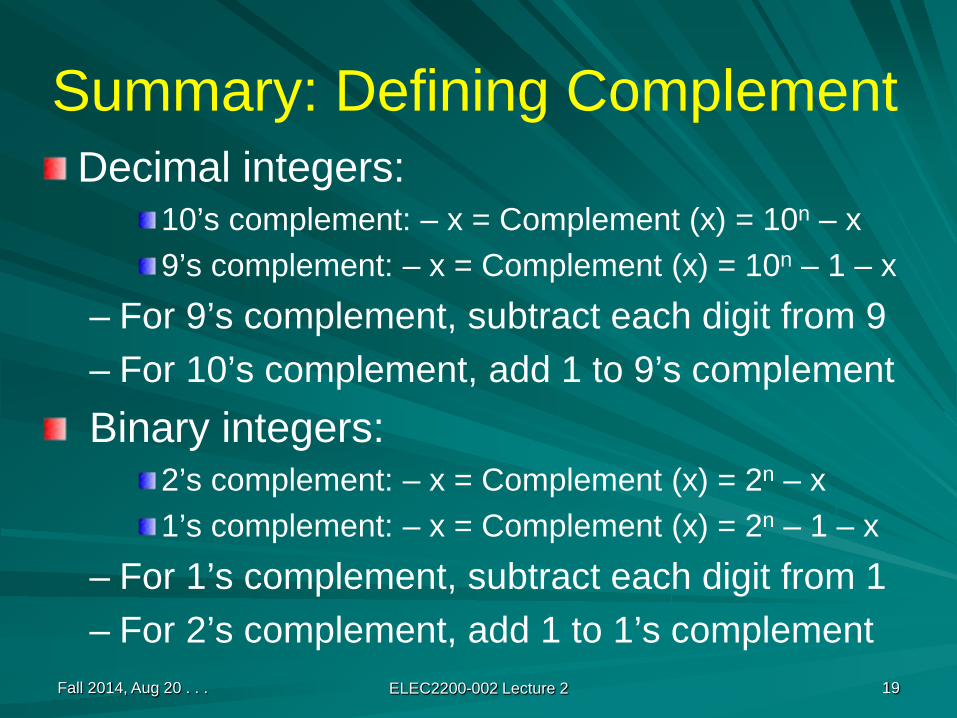
Summary: Defining ComplementDecimal integers:
10’s complement: – x = Complement (x) = 10n – x 9’s complement: – x = Complement (x) = 10n – 1 – x
– For 9’s complement, subtract each digit from 9– For 10’s complement, add 1 to 9’s complementBinary integers:
2’s complement: – x = Complement (x) = 2n – x 1’s complement: – x = Complement (x) = 2n – 1 – x
– For 1’s complement, subtract each digit from 1– For 2’s complement, add 1 to 1’s complement
Fall 2014, Aug 20 . . . ELEC2200-002 Lecture 2 19
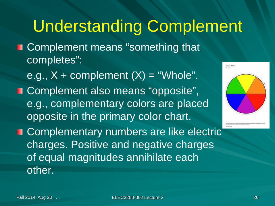
Understanding ComplementComplement means “something that completes”:e.g., X + complement (X) = “Whole”.Complement also means “opposite”, e.g., complementary colors are placed opposite in the primary color chart.Complementary numbers are like electric charges. Positive and negative charges of equal magnitudes annihilate each other.
Fall 2014, Aug 20 . . . ELEC2200-002 Lecture 2 20

2’s-Complement Numbers
Fall 2014, Aug 20 . . . ELEC2200-002 Lecture 2 21
. . . -1 0 1 2 3 4 5 . . .000 001 010 011 100 101
Infiniteuniverseof integers
∞-∞
000
499
500
1000
001999
501
FiniteUniverse of3-digitDecimalnumbers
000
011
100
1000
001111
101
FiniteUniverseof 3-bitbinarynumbers

Examples of ComplementsDecimal integers (r = 10, n = 3):
10’s complement: – 50 = Compl (50) = 103 – 50 = 950; 50 + 950 = 1,000 = 0 (in 3 digit representation)9’s complement: – 50 = Compl (50) = 10n – 1 – 50 = 949; 50 + 949 = 999 = – 0 (in 9’s complement rep.)
Binary integers (r = 2, n = 4):2’s complement: – 5 = Complement (5) = 24 – 5 = 1110 or 1011; 5 + 11 = 16 = 0 (in 4-bit representation)1’s complement: – 5 = Complement (5) = 24 – 1 – 5 = 1010 or 1010; 5 + 10 = 15 = – 0 (in 1’s complement representation)
Fall 2014, Aug 20 . . . ELEC2200-002 Lecture 2 22

Fall 2014, Aug 20 . . . ELEC2200-002 Lecture 2 23
2’s-Complement to Decimal Conversion
bn-1 bn-2 . . . b1 b0 = – 2n-1bn-1 + Σ 2i bii=0
n-2
-128 64 32 16 8 4 2 18-bit conversion box
-128 64 32 16 8 4 2 11 1 1 1 1 1 0 1
Example
– 128 + 64 + 32 + 16 + 8 + 4 + 1 = – 128 + 125 = – 3

Fall 2014, Aug 20 . . . ELEC2200-002 Lecture 2 24
For More on 2’s-Complement
Chapter 4 in D. E. Knuth, The Art of Computer Programming: Seminumerical Algorithms, Volume II, Second Edition, Addison-Wesley, 1981.A. al’Khwarizmi, Hisab al-jabr w’al-muqabala, 830.Read: A two part interview with D. E. Knuth, Communications of the ACM (CACM), vol. 51, no. 7, pp. 35-39 (July), and no. 8, pp. 31-35 (August), 2008.
Donald E. Knuth (1938 - ) Abu Abd-Allah ibn Musa al’Khwarizmi (~780 – 850)
Fall 2014, Aug 20 . . . ELEC2200-002 Lecture 2 25
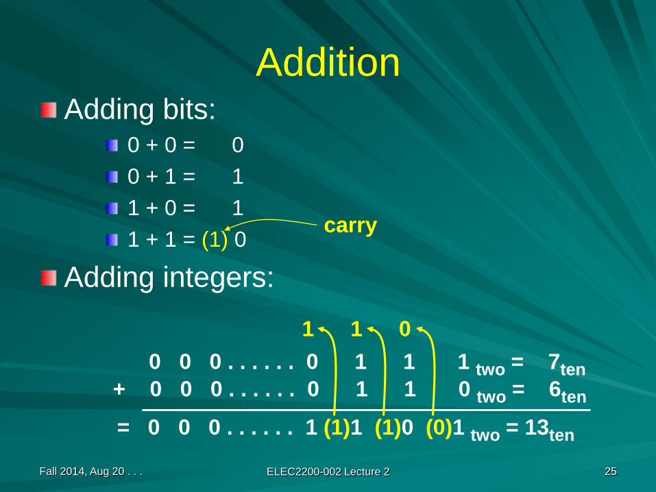
AdditionAdding bits:
0 + 0 = 00 + 1 = 11 + 0 = 11 + 1 = (1) 0
Adding integers:
carry
0 0 0 . . . . . . 0 1 1 1 two = 7ten+ 0 0 0 . . . . . . 0 1 1 0 two = 6ten
= 0 0 0 . . . . . . 1 (1)1 (1)0 (0)1 two = 13ten
1 1 0

Fall 2014, Aug 20 . . . ELEC2200-002 Lecture 2 26
SubtractionDirect subtraction
Two’s complement subtraction by adding
0 0 0 . . . . . . 0 1 1 1 two = 7ten– 0 0 0 . . . . . . 0 1 1 0 two = 6ten
= 0 0 0 . . . . . . 0 0 0 1two = 1ten
0 0 0 . . . . . . 0 1 1 1 two = 7ten+ 1 1 1 . . . . . . 1 0 1 0 two = – 6ten
= 0 0 0 . . . . . . 0 (1) 0 (1) 0 (0)1 two = 1ten
1 1 1 . . . . . . 1 1 0

Fall 2014, Aug 20 . . . ELEC2200-002 Lecture 2 27
Overflow: An ErrorExamples: Addition of 3-bit integers (range - 4 to +3)
-2-3 = -5 110 = -2+ 101 = -3= 1011 = 3 (error)
3+2 = 5 011 = 3010 = 2
= 101 = -3 (error)
Overflow rule: If two numbers with the same sign bit (both positive or both negative) are added, the overflow occurs if and only if the result has the opposite sign.
01
2
3
-1
-2
-3 - 4
000001
010
011
100
101
110
111
– +
Overflowcrossing

Overflow and Finite Universe
Fall 2014, Aug 20 . . . ELEC2200-002 Lecture 2 28
. . .1111 0000 0001 0010 0011 0100 0101 . . .Decrease Increase
Infiniteuniverseof integersNo overflow
∞-∞
0000
Forbidden fence1000
00011111
1001
FiniteUniverseof 4-bitbinaryintegers
0010
00110100
01010110
01111010
1011
11001101
1110
Incr
ease
Dec
reas
e

Adding Two Bits
a bs = a + b
Decimal Binary0 0 0 000 1 1 011 0 1 011 1 2 10
Fall 2014, Aug 20 . . . ELEC2200-002 Lecture 2 29
SUMCARRY
Fall 2014, Aug 20 . . . ELEC2200-002 Lecture 2 30
HA
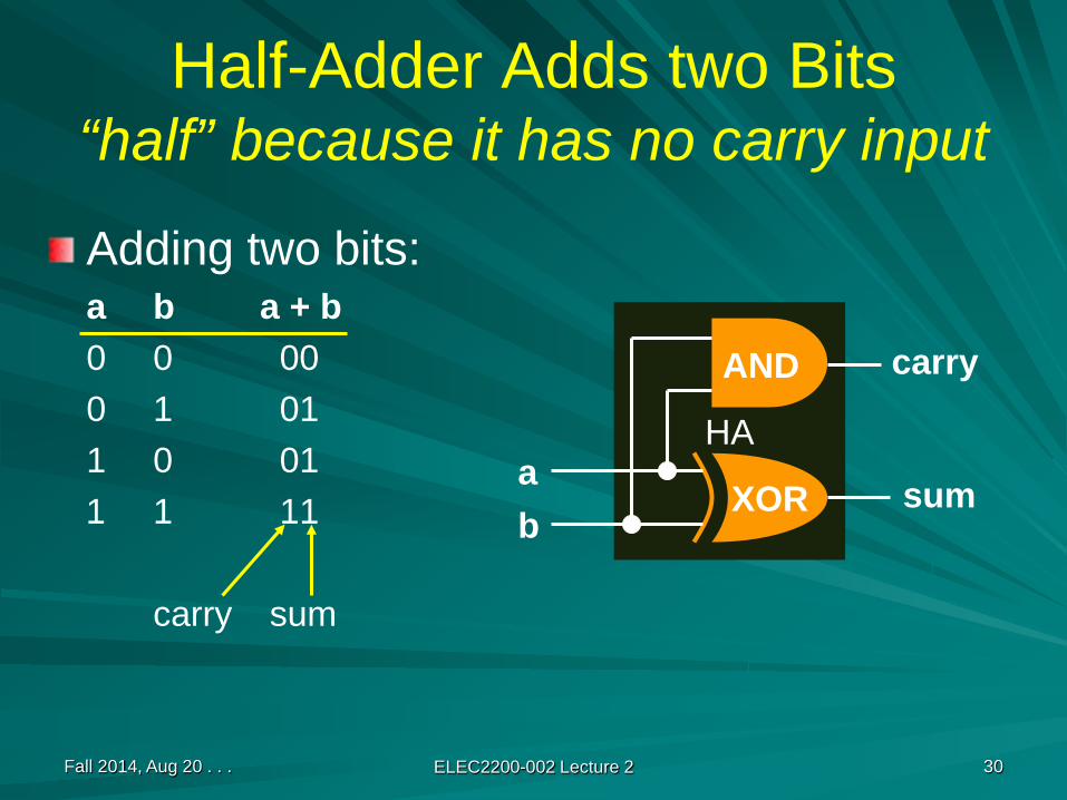
Half-Adder Adds two Bits“half” because it has no carry input
Adding two bits:a b a + b0 0 000 1 011 0 011 1 11
carry sum
ab
sum
carry
XOR
AND

Full Adder: Include Carry Inputa b c
s = a + b + cDecimal value Binary value
0 0 0 0 000 0 1 1 010 1 0 1 010 1 1 2 101 0 0 1 011 0 1 2 101 1 0 2 101 1 1 3 11
Fall 2014, Aug 20 . . . ELEC2200-002 Lecture 2 31
SUMCARRY
Fall 2014, Aug 20 . . . ELEC2200-002 Lecture 2 32
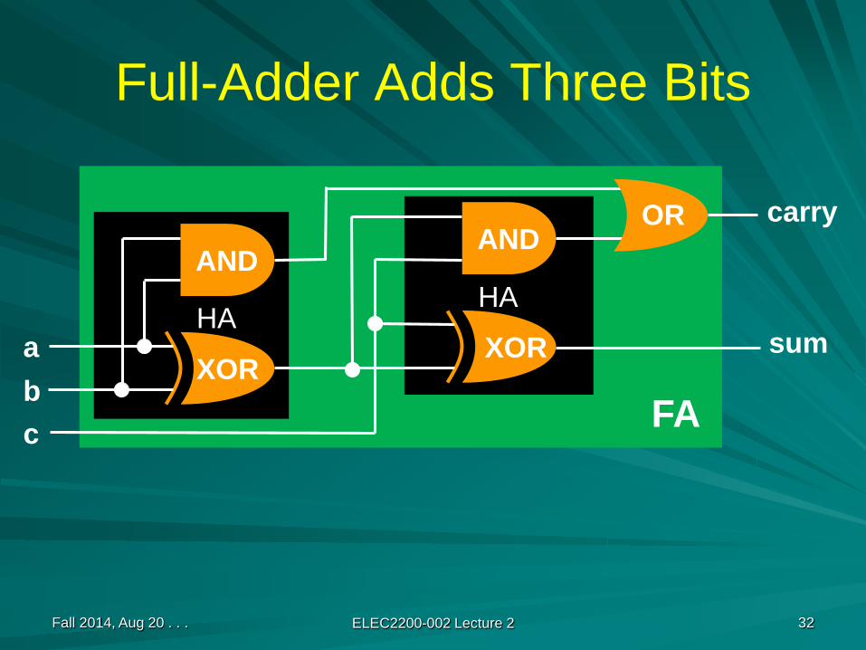
Full-Adder Adds Three Bits
ab
XOR
AND
XOR
ANDOR
c
sum
carry
FA
HAHA

Fall 2014, Aug 20 . . . ELEC2200-002 Lecture 2 33
32-bit Ripple-Carry Adder
FA0FA1
FA2
FA31
a0b0c0 = 0
a1b1
a2b2
a31b31
s0
s1s2
c32(discard)
s31c31
c2c1
c32 c31 . . . c2 c1 0a31 . . . a2 a1 a0
+ b31 . . . b2 b1 b0s31 . . . s2 s1 s0
Fall 2014, Aug 20 . . . ELEC2200-002 Lecture 2 34
How Fast is Ripple-Carry Adder?
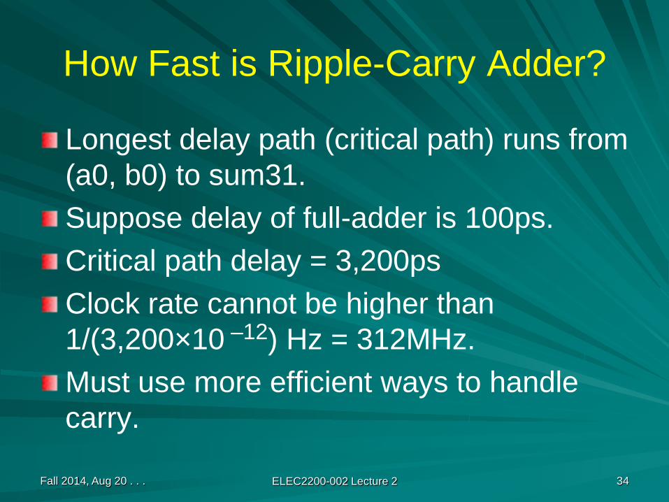
Longest delay path (critical path) runs from (a0, b0) to sum31.Suppose delay of full-adder is 100ps.Critical path delay = 3,200psClock rate cannot be higher than 1/(3,200×10 –12) Hz = 312MHz.Must use more efficient ways to handle carry.

Fall 2014, Aug 20 . . . ELEC2200-002 Lecture 2 35
Speeding Up the Adder16-bitripplecarryadder
a0-a15
b0-b15
c0 = 0
s0-s15
16-bitripplecarryadder
a16-a31
b16-b31
0
16-bitripplecarryadder
a16-a31
b16-b31
1
Mul
tiple
xer
s16-s31
0
1
This is a carry-select adder

Fall 2014, Aug 20 . . . ELEC2200-002 Lecture 2 36
Fast AddersIn general, any output of a 32-bit adder can be evaluated as a logic expression in terms of all 65 inputs.Number of levels of logic can be reduced to log2N for N-bit adder. Ripple-carry has N levels.More gates are needed, about log2N times that of ripple-carry design.Fastest design is known as carry lookahead adder.

Fall 2014, Aug 20 . . . ELEC2200-002 Lecture 2 37
N-bit Adder Design OptionsType of adder Time complexity
(delay)Space complexity
(size)Ripple-carry O(N) O(N)
Carry-lookahead O(log2N) O(N log2N)
Carry-skip O(√N) O(N)
Carry-select O(√N) O(N)
Reference: J. L. Hennessy and D. A. Patterson, Computer Architecture: A Quantitative Approach, Second Edition, San Francisco, California, 1990, page A-46.
Fall 2014, Aug 20 . . . ELEC2200-002 Lecture 2 38
Binary Multiplication (Unsigned)
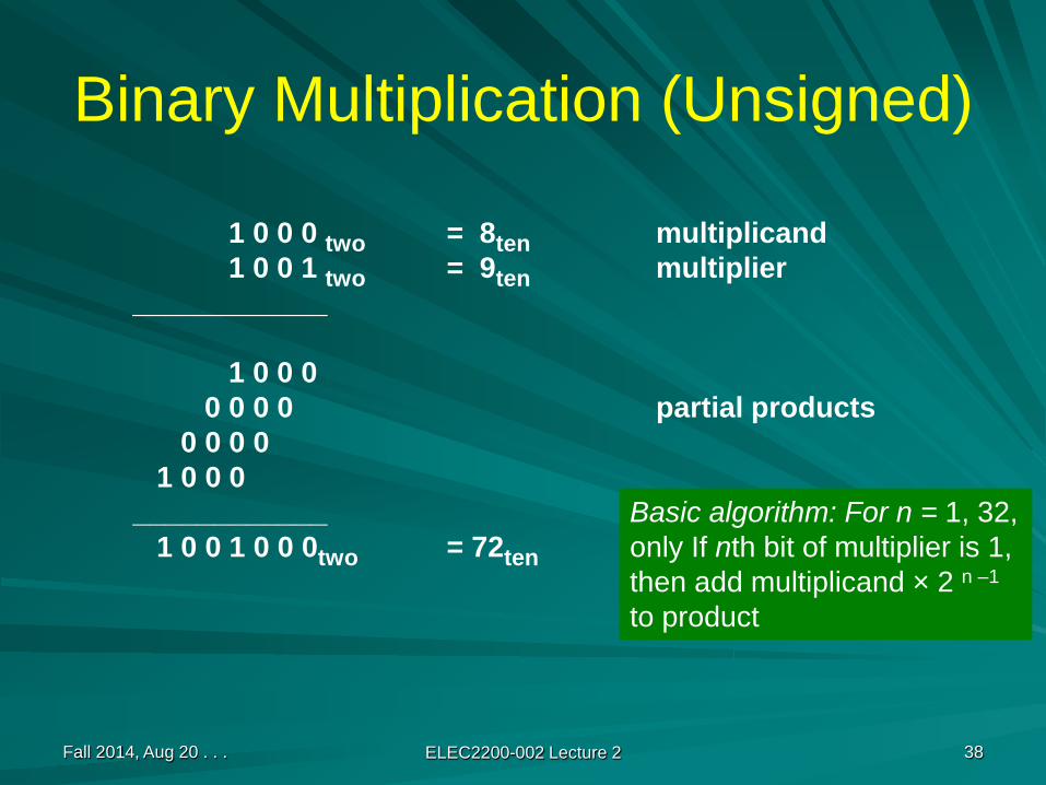
1 0 0 0 two = 8ten multiplicand1 0 0 1 two = 9ten multiplier
____________
1 0 0 00 0 0 0 partial products
0 0 0 01 0 0 0
____________1 0 0 1 0 0 0two = 72ten
Basic algorithm: For n = 1, 32,only If nth bit of multiplier is 1,then add multiplicand × 2 n –1
to product

Digital Circuits for MultiplicationNeed:
Three registers for multiplicand, multiplier and product.Adder or arithmetic logic unit (ALU).
What is a registerA memory device – unit cell stores one bit.A 32-bit register has 32 storage cells. It can store a 32-bit integer.
Fall 2014, Aug 20 . . . ELEC2200-002 Lecture 2 39
bit 0bit 321 bit right shift divides integer by 2
1 bit left shift multiplies integer by 2

Fall 2014, Aug 20 . . . ELEC2200-002 Lecture 2 40
LSBof multiplier
?
Multiplication FlowchartInitialize product register to 0 Partial product number, n = 1
Left shift multiplicand register 1 bit
Right shift multiplier register 1 bit
n = ? n = n + 1Done
Start
Add multiplicand toproduct and place result
in product register
1 0
n < 32n = 32
N = 32

Fall 2014, Aug 20 . . . ELEC2200-002 Lecture 2 41
Serial Multiplication
64-bit product register
64
64
64
64-bit ALU Test LSB32 times
shift right
32-bit multiplier
shift left
write3 operations per bit:
shift rightshift leftadd
Need 64-bit ALU
Multiplicand (expanded 64-bits)
LSB = 0LSB= 1
add
Shift
l/r
Shift
l/r
afte
r add
N = 32

Fall 2014, Aug 20 . . . ELEC2200-002 Lecture 2 42
Serial Multiplication (Improved)Multiplicand
64-bit product register
32
32
32
32-bit ALU Test LSB32 timesLSB
(3) shift right
00000 . . . 00000 32-bit multiplier Initialized product register
2 operations per bit:shift rightadd
32-bit ALU
1
1(1) add
1 or 0
N = 32

Fall 2014, Aug 20 . . . ELEC2200-002 Lecture 2 43
Example: 0010two× 0011two
Iteration Step Multiplicand Product0 Initial values 0010 0000 00111 LSB =1 → Prod = Prod + Mcand 0010 0010 0011
Right shift product 0010 0001 00012 LSB =1 → Prod = Prod + Mcand 0010 0011 0001
Right shift product 0010 0001 10003 LSB = 0 → no operation 0010 0001 1000
Right shift product 0010 0000 11004 LSB = 0 → no operation 0010 0000 1100
Right shift product 0010 0000 0110
0010two × 0011two = 0110two, i.e., 2ten × 3ten = 6ten
Fall 2014, Aug 20 . . . ELEC2200-002 Lecture 2 44
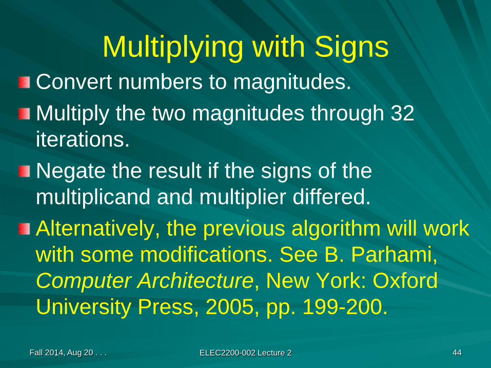
Multiplying with SignsConvert numbers to magnitudes.Multiply the two magnitudes through 32 iterations.Negate the result if the signs of the multiplicand and multiplier differed.Alternatively, the previous algorithm will work with some modifications. See B. Parhami, Computer Architecture, New York: Oxford University Press, 2005, pp. 199-200.

Alternative Method with Signs
In the improved method:Use 2N + 1 bit product registerUse N + 1 bit multiplicand registerUse N + 1 bit adder
Proceed as in the improved method, except –In the last (Nth) iteration, if LSB = 1, subtract multiplicand instead of adding.
Fall 2014, Aug 20 . . . ELEC2200-002 Lecture 2 45

Fall 2014, Aug 20 . . . ELEC2200-002 Lecture 2 46
Example 1: 1010two× 0011two
Iteration Step Multiplicand Product0 Initial values 11010 00000 00111 LSB = 1 → Prod = Prod + Mcand 11010 11010 0011
Right shift product 11010 11101 00012 LSB = 1 → Prod = Prod + Mcand 11010 10111 0001
Right shift product 11010 11011 10003 LSB = 0 → no operation 11010 11011 1000
Right shift product 11010 11101 11004 LSB = 0 → no operation 11010 11101 1100
Right shift product 11010 11110 1110
1010two × 0011two = 101110two, i.e., – 6ten × 3ten = – 18ten

Fall 2014, Aug 20 . . . ELEC2200-002 Lecture 2 47
Example 2: 1010two× 1011two
Iteration Step Multiplicand Product0 Initial values 11010 00000 10111 LSB =1 → Prod = Prod + Mcand 11010 11010 1011
Right shift product 11010 11101 01012 LSB =1 → Prod = Prod + Mcand 11010 10111 0101
Right shift product 11010 11011 10103 LSB = 0 → no operation 11010 11011 1010
Right shift product 11010 11101 11014 LSB =1 → Prod = Prod – Mcand* 00110 00011 1101
Right shift product 11010 00001 1110
1010two × 1011two = 011110two, i.e., – 6ten × ( – 5ten) = 30ten
*Last iteration with a negative multiplier in 2’s complement.
Fall 2014, Aug 20 . . . ELEC2200-002 Lecture 2 48
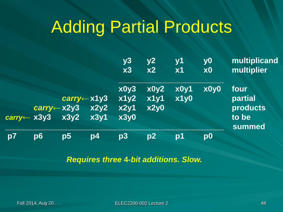
Adding Partial Products
y3 y2 y1 y0 multiplicandx3 x2 x1 x0 multiplier
________________________x0y3 x0y2 x0y1 x0y0 four
carry← x1y3 x1y2 x1y1 x1y0 partialcarry← x2y3 x2y2 x2y1 x2y0 products
carry← x3y3 x3y2 x3y1 x3y0 to be__________________________________________________ summedp7 p6 p5 p4 p3 p2 p1 p0
Requires three 4-bit additions. Slow.

Fall 2014, Aug 20 . . . ELEC2200-002 Lecture 2 49
Array Multiplier: Carry Forward
y3 y2 y1 y0 multiplicandx3 x2 x1 x0 multiplier
________________________x0y3 x0y2 x0y1 x0y0 four
x1y3 x1y2 x1y1 x1y0 partialx2y3 x2y2 x2y1 x2y0 products
x3y3 x3y2 x3y1 x3y0 to be__________________________________________________ summedp7 p6 p5 p4 p3 p2 p1 p0
Note: Carry is added to the next partial product (carry-save addition).Adding the carry from the final stage needs an extra (ripple-carrystage. These additions are faster but we need four stages.

Fall 2014, Aug 20 . . . ELEC2200-002 Lecture 2 50
Basic Building Blocks
Two-input ANDFull-adder
Fulladder
yi x0
p0i = x0yi
0th partial productsum bit
to (k+1)thsum
sum bitfrom (k-1)th
sum
yi xk
carry bitsfrom (k-1)th
sum
carry bitsto (k+1)th
sum
Slide 24
ith bit ofkth partialproduct

Fall 2014, Aug 20 . . . ELEC2200-002 Lecture 2 51
Array Multipliery3 y2 y1 y0
x0
x1
x2
x3
FA
xiyjppk
ppk+1co
0
0
0
ci
0
0 0 0 0
p7 p6 p5 p4 p3 p2 p1 p0FA FA FA FA
Critical path0
Fall 2014, Aug 20 . . . ELEC2200-002 Lecture 2 52
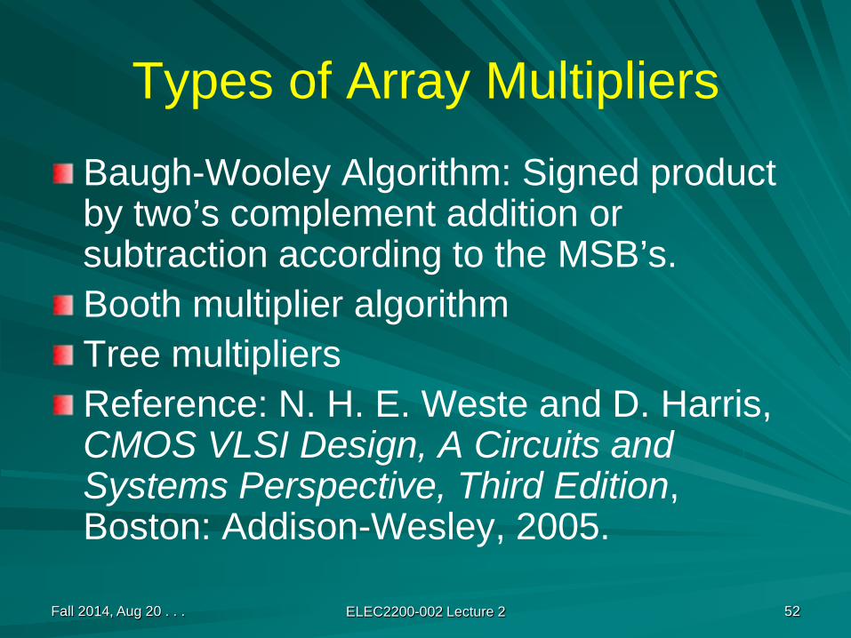
Types of Array Multipliers
Baugh-Wooley Algorithm: Signed product by two’s complement addition or subtraction according to the MSB’s.Booth multiplier algorithmTree multipliersReference: N. H. E. Weste and D. Harris, CMOS VLSI Design, A Circuits and Systems Perspective, Third Edition, Boston: Addison-Wesley, 2005.

Fall 2014, Aug 20 . . . ELEC2200-002 Lecture 2 53
Binary Division (Unsigned)
1 3 Quotient1 1 / 1 4 7 Divisor / Dividend
1 13 7 Partial remainder3 3
4 Remainder
0 0 0 0 1 1 0 11 0 1 1 / 1 0 0 1 0 0 1 1
1 0 1 10 0 1 1 1 0
1 0 1 10 0 1 1 1 1
1 0 1 11 0 0

Fall 2014, Aug 20 . . . ELEC2200-002 Lecture 2 54
4-bit Binary Division (Unsigned)Dividend: 6 = 0110Divisor: 4 = 0100
– 4 = 1100
6─ = 1, remainder 24
0 0 0 10 0 0 0 1 1 01 1 0 01 1 0 0 negative → quotient bit 00 1 0 0 → restore remainder0 0 0 0 1 1 0
1 1 0 01 1 0 1 negative → quotient bit 00 1 0 0 → restore remainder0 0 0 1 1 0
1 1 0 01 1 1 1 negative → quotient bit 00 1 0 0 → restore remainder0 0 1 1 0
1 1 0 00 0 1 0 positive → quotient bit 1It
erat
ion
4 I
tera
tion
3
Ite
rati
on 2
It
erat
ion
1

Fall 2014, Aug 20 . . . ELEC2200-002 Lecture 2 55
32-bit Binary Division Flowchart$R = 0, $M = Divisor, $Q = Dividend, count = n
Shift 1-bit left $R, $Q
$R ← $R – $M
$R < 0?$Q0 = 1 $Q0=0$R ← $R + $M
count = count – 1
count = 0?Done
$Q = Quotient$R = Remainder
Start
Yes
Yes
No
No
$R and $M haveone extra sign bitbeyond 32 bits.
Restore $R(remainder)
$R (33 b) | $Q (32 b)
Fall 2014, Aug 20 . . . ELEC2200-002 Lecture 2 56
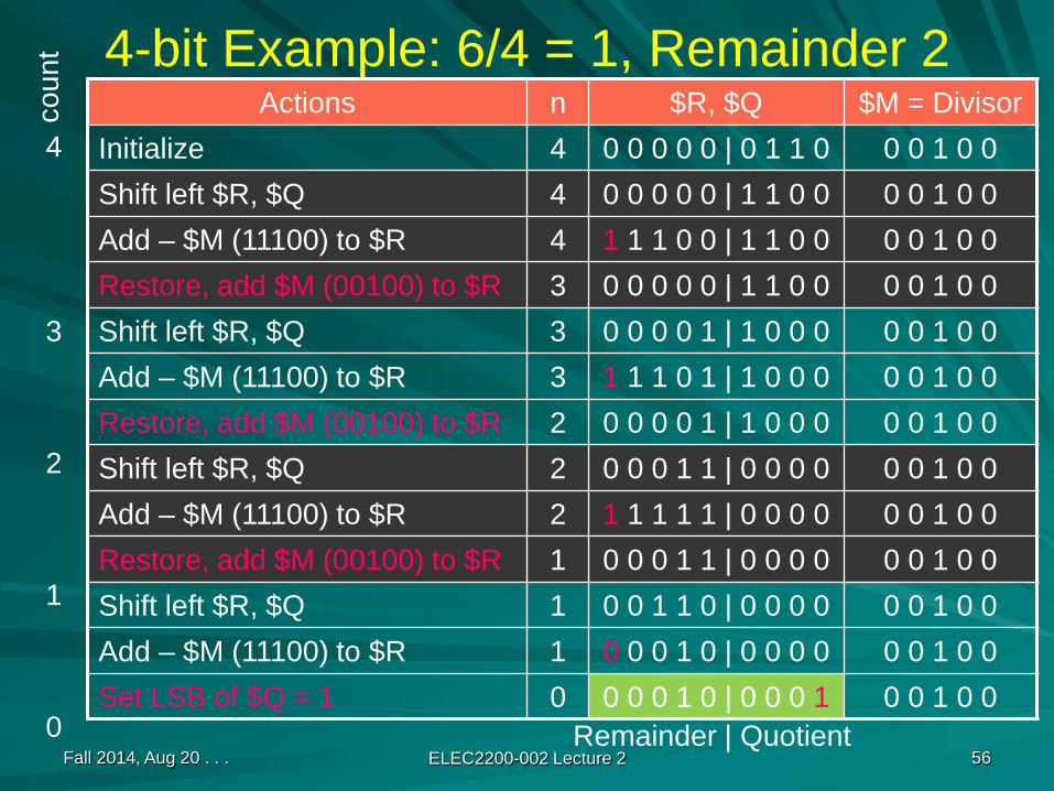
4-bit Example: 6/4 = 1, Remainder 2Actions n $R, $Q $M = Divisor
Initialize 4 0 0 0 0 0 | 0 1 1 0 0 0 1 0 0Shift left $R, $Q 4 0 0 0 0 0 | 1 1 0 0 0 0 1 0 0Add – $M (11100) to $R 4 1 1 1 0 0 | 1 1 0 0 0 0 1 0 0Restore, add $M (00100) to $R 3 0 0 0 0 0 | 1 1 0 0 0 0 1 0 0Shift left $R, $Q 3 0 0 0 0 1 | 1 0 0 0 0 0 1 0 0Add – $M (11100) to $R 3 1 1 1 0 1 | 1 0 0 0 0 0 1 0 0Restore, add $M (00100) to $R 2 0 0 0 0 1 | 1 0 0 0 0 0 1 0 0Shift left $R, $Q 2 0 0 0 1 1 | 0 0 0 0 0 0 1 0 0Add – $M (11100) to $R 2 1 1 1 1 1 | 0 0 0 0 0 0 1 0 0Restore, add $M (00100) to $R 1 0 0 0 1 1 | 0 0 0 0 0 0 1 0 0Shift left $R, $Q 1 0 0 1 1 0 | 0 0 0 0 0 0 1 0 0Add – $M (11100) to $R 1 0 0 0 1 0 | 0 0 0 0 0 0 1 0 0Set LSB of $Q = 1 0 0 0 0 1 0 | 0 0 0 1 0 0 1 0 0
Remainder | Quotient
coun
t
4
3
2
1
0

Fall 2014, Aug 20 . . . ELEC2200-002 Lecture 2 57
Initialize$R←0
Division33-bit $M (Divisor)
33-bit $R (Remainder)
33
33
33
33-bit ALU
32 timesStep 1: 1- bit left shift $R and $Q
32-bit $Q (Dividend)
Step 2: Subtract $R ← $R – $M
Step 3: If sign-bit ($R) = 0, set Q0 = 1If sign-bit ($R) = 1, set Q0 = 0 and restore $R
V. C. Hamacher, Z. G. Vranesic and S. G. Zaky, Computer Organization, Fourth Edition,New York: McGraw-Hill, 1996.
Fall 2014, Aug 20 . . . ELEC2200-002 Lecture 2 58
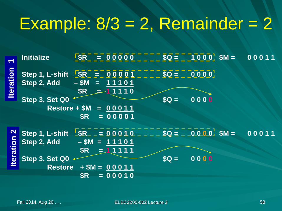
Example: 8/3 = 2, Remainder = 2
Initialize $R = 0 0 0 0 0 $Q = 1 0 0 0 $M = 0 0 0 1 1
Step 1, L-shift $R = 0 0 0 0 1 $Q = 0 0 0 0Step 2, Add – $M = 1 1 1 0 1
$R = 1 1 1 1 0Step 3, Set Q0 $Q = 0 0 0 0
Restore + $M = 0 0 0 1 1$R = 0 0 0 0 1
Step 1, L-shift $R = 0 0 0 1 0 $Q = 0 0 0 0 $M = 0 0 0 1 1Step 2, Add – $M = 1 1 1 0 1
$R = 1 1 1 1 1Step 3, Set Q0 $Q = 0 0 0 0
Restore + $M = 0 0 0 1 1$R = 0 0 0 1 0
Itera
tion
2Ite
ratio
n 1

Fall 2014, Aug 20 . . . ELEC2200-002 Lecture 2 59
Example: 8/3 = 2 (Remainder = 2) (Continued)
$R = 0 0 0 1 0 $Q = 0 0 0 0 $M = 0 0 0 1 1
Step 1, L-shift $R = 0 0 1 0 0 $Q = 0 0 0 0 $M = 0 0 0 1 1Step 2, Add – $M = 1 1 1 0 1
$R = 0 0 0 0 1Step 3, Set Q0 $Q = 0 0 0 1
Step 1, L-shift $R,Q = 0 0 0 1 0 $Q = 0 0 1 0 $M = 0 0 0 1 1Step 2, Add – $M = 1 1 1 0 1
$R = 1 1 1 1 1Step 3, Set Q0 $Q = 0 0 1 0 Final quotient
Restore + $M = 0 0 0 1 1$R = 0 0 0 1 0Ite
ratio
n 4
Itera
tion
3
Note “Restore $R” in Steps 1, 2 and 4. This method is known asthe RESTORING DIVISION. An improved method, NON-RESTORINGDIVISION, is possible (see Hamacher, et al.)
Remainder

Non-Restoring DivisionAvoid unnecessary addition (restoration).How it works?– Initially $R contains dividend ✕ 2 – n for n-bit numbers. Example (n = 8):
– In some iteration after left shift, suppose $R = x and divisor is y– Subtract divisor, $R = x – y – Restore: If $R is negative, add y, $R = x– Next step: Left shift, $R = 2x+b, and subtract y, $R = 2x – y + b
Fall 2014, Aug 20 . . . ELEC2200-002 Lecture 2 60
00101101
00000000 00101101
Dividend
$R, $Q

How It Works: Last two Steps– Suppose we do not restore and go to next step:– Left shift, $R = 2(x – y) + b = 2x – 2y + b, and add y, then $R = 2x
– 2y + y + b = 2x – y + b (same result as with restoration)
Non-restoring divisionInitialize and start iterations same as in restoring division by subtracting divisorIn any iteration after left shift and subtraction/addition
– If $R is positive, subtract divisor (y) in next iteration– If $R is negative, add divisor (y) in next iteration
After final iteration, if $R is negative then restore it by adding divisor (y)
Fall 2014, Aug 20 . . . ELEC2200-002 Lecture 2 61
Fall 2014, Aug 20 . . . ELEC2200-002 Lecture 2 62
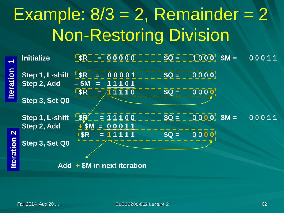
Example: 8/3 = 2, Remainder = 2Non-Restoring Division
Initialize $R = 0 0 0 0 0 $Q = 1 0 0 0 $M = 0 0 0 1 1
Step 1, L-shift $R = 0 0 0 0 1 $Q = 0 0 0 0Step 2, Add – $M = 1 1 1 0 1
$R = 1 1 1 1 0 $Q = 0 0 0 0Step 3, Set Q0
Step 1, L-shift $R = 1 1 1 0 0 $Q = 0 0 0 0 $M = 0 0 0 1 1Step 2, Add + $M = 0 0 0 1 1
$R = 1 1 1 1 1 $Q = 0 0 0 0Step 3, Set Q0
Itera
tion
2Ite
ratio
n 1
Add + $M in next iteration

Fall 2014, Aug 20 . . . ELEC2200-002 Lecture 2 63
Example: 8/3 = 2 (Remainder = 2) Non-Restoring Division (Continued)
$R = 1 1 1 1 1 $Q = 0 0 0 0 $M = 0 0 0 1 1
Step 1, L-shift $R = 1 1 1 1 0 $Q = 0 0 0 0 $M = 0 0 0 1 1Step 2, Add + $M = 0 0 0 1 1
$R = 0 0 0 0 1 $Q = 0 0 0 1Step 3, Set Q0
Step 1, L-shift $R,Q = 0 0 0 1 0 $Q = 0 0 1 0 $M = 0 0 0 1 1Step 2, Add – $M = 1 1 1 0 1
$R = 1 1 1 1 1 $Q = 0 0 1 0 Final quotient = 2Step 3, Set Q0
Restore + $M = 0 0 0 1 1$R = 0 0 0 1 0Ite
ratio
n 4
Itera
tion
3
See, V. C. Hamacher, Z. G. Vranesic and Z. G. Zaky, Computer Organization, Fourth Edition, McGraw-Hill, 1996, Section 6.9, pp. 281-285.
Remainder = 2
Fall 2014, Aug 20 . . . ELEC2200-002 Lecture 2 64
Signed Division
Remember the signs and divide magnitudes.Negate the quotient if the signs of divisor and dividend disagree.There is no other direct division method for signed division.
Fall 2014, Aug 20 . . . ELEC2200-002 Lecture 2 65
Symbol RepresentationEarly versions (60s and 70s)
Six-bit binary code (Control Data Corp., CDC)EBCDIC – extended binary coded decimal interchange code (IBM)
Presently used –ASCII – American standard code for information interchange – 7 bit code specified by American National Standards Institute (ANSI), see Table 1.11 on page 63; an eighth MSB is often used as parity bit to construct a byte-code.Unicode – 16 bit code and an extended 32 bit version
Fall 2014, Aug 20 . . . ELEC2200-002 Lecture 2 66
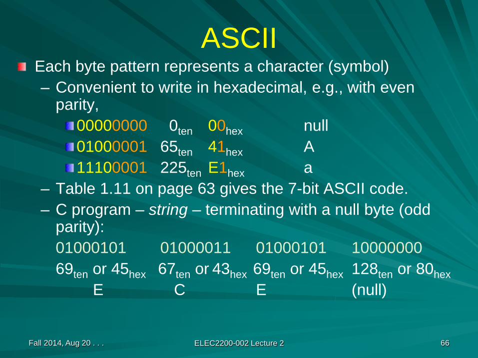
ASCIIEach byte pattern represents a character (symbol)– Convenient to write in hexadecimal, e.g., with even
parity,00000000 0ten 00hex null01000001 65ten 41hex A11100001 225ten E1hex a
– Table 1.11 on page 63 gives the 7-bit ASCII code.– C program – string – terminating with a null byte (odd
parity):01000101 01000011 01000101 1000000069ten or 45hex 67ten or 43hex 69ten or 45hex 128ten or 80hex
E C E (null)

Error Detection CodeErrors: Bits can flip due to noise in circuits and in communication.Extra bits used for error detection.Example: a parity bit in ASCII code
Fall 2014, Aug 20 . . . ELEC2200-002 Lecture 2 67
Even parity code for A 01000001(even number of 1s)
Odd parity code for A 11000001(odd number of 1s)
7-bit ASCII code
Parity bits
Single-bit error in 7-bit code of “A”, e.g., 1000101, will changesymbol to “E” or 1000000 to “@”. But error will be detected inthe 8-bit code because the error changes the specified parity.
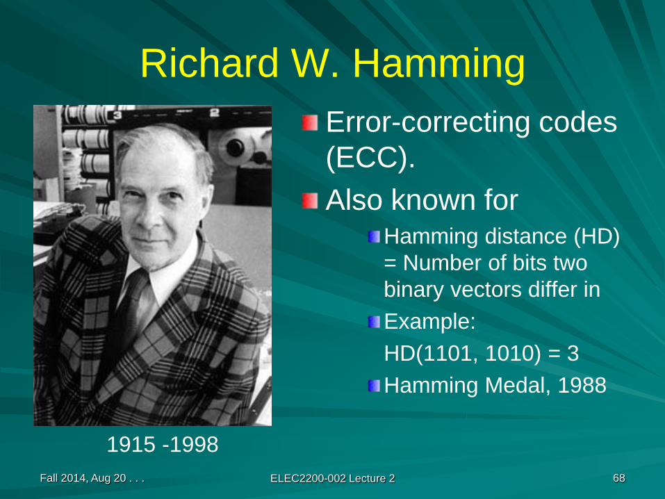
Richard W. HammingError-correcting codes (ECC).Also known for
Hamming distance (HD) = Number of bits two binary vectors differ inExample:HD(1101, 1010) = 3Hamming Medal, 1988
Fall 2014, Aug 20 . . . ELEC2200-002 Lecture 2 68
1915 -1998
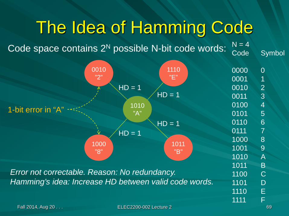
The Idea of Hamming Code
Fall 2014, Aug 20 . . . ELEC2200-002 Lecture 2 69
Code space contains 2N possible N-bit code words:
1010”A”
1110”E”
1011”B”
1000”8”
0010”2”
1-bit error in “A”
HD = 1HD = 1
HD = 1HD = 1
Error not correctable. Reason: No redundancy.Hamming’s idea: Increase HD between valid code words.
N = 4Code Symbol
0000 00001 10010 20011 30100 40101 50110 60111 71000 81001 91010 A1011 B1100 C1101 D1110 E1111 F
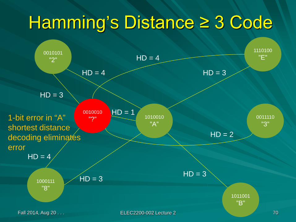
Hamming’s Distance ≥ 3 Code
Fall 2014, Aug 20 . . . ELEC2200-002 Lecture 2 70
1010010”A”
1-bit error in “A”shortest distancedecoding eliminateserror
HD = 2
HD = 1
0010101”2”
1000111”8”
1011001”B”
1110100”E”
HD = 3
HD = 3
HD = 3
HD = 4
0010010”?”
HD = 3
HD = 4
HD = 4
0011110”3”
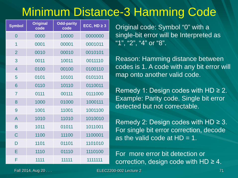
Minimum Distance-3 Hamming CodeSymbol Original
codeOdd-parity
code ECC, HD ≥ 3
0 0000 10000 0000000
1 0001 00001 0001011
2 0010 00010 0010101
3 0011 10011 0011110
4 0100 00100 0100110
5 0101 10101 0101101
6 0110 10110 0110011
7 0111 00111 0111000
8 1000 01000 1000111
9 1001 11001 1001100
A 1010 11010 1010010
B 1011 01011 1011001
C 1100 11100 1100001
D 1101 01101 1101010
E 1110 01110 1110100
F 1111 11111 1111111
Fall 2014, Aug 20 . . . ELEC2200-002 Lecture 2 71
Original code: Symbol “0” with a single-bit error will be Interpreted as“1”, “2”, “4” or “8”.
Reason: Hamming distance betweencodes is 1. A code with any bit error willmap onto another valid code.
Remedy 1: Design codes with HD ≥ 2.Example: Parity code. Single bit errordetected but not correctable.
Remedy 2: Design codes with HD ≥ 3.For single bit error correction, decodeas the valid code at HD = 1.
For more error bit detection orcorrection, design code with HD ≥ 4.
Fall 2014, Aug 20 . . . ELEC2200-002 Lecture 2 72
Integers and Real NumbersIntegers: the universe is infinite but discrete– No fractions– No numbers between consecutive integers, e.g., 5 and 6– A countable (finite) number of items in a finite range– Referred to as fixed-point numbers
Real numbers – the universe is infinite and continuous– Fractions represented by decimal notation
Rational numbers, e.g., 5/2 = 2.5Irrational numbers, e.g., 22/7 = 3.14159265 . . .
– Infinite numbers exist even in the smallest range– Referred to as floating-point numbers

Fall 2014, Aug 20 . . . ELEC2200-002 Lecture 2 73
Wide Range of Numbers
A large number:976,000,000,000,000 = 9.76 × 10¹⁴
A small number:0.0000000000000976 = 9.76 × 10 –14
Fall 2014, Aug 20 . . . ELEC2200-002 Lecture 2 74
Scientific NotationDecimal numbers
0.513×10⁵, 5.13×10⁴ and 51.3×10³ are written in scientific notation.5.13×104 is the normalized scientific notation.
Binary numbersBase 2Binary point – multiplication by 2 moves the point to the right.Normalized scientific notation, e.g., 1.0two×2 –1

Fall 2014, Aug 20 . . . ELEC2200-002 Lecture 2 75
Floating Point NumbersGeneral format
±1.bbbbbtwo×2eeee
or (-1)S × (1+F) × 2E
WhereS = sign, 0 for positive, 1 for negativeF = fraction (or mantissa) as a binary integer,
1+F is called significandE = exponent as a binary integer, positive or
negative (two’s complement)

Fall 2014, Aug 20 . . . ELEC2200-002 Lecture 2 76
Binary to Decimal Conversion
Binary (-1)S (1.b1b2b3b4) × 2E
Decimal (-1)S × (1 + b1×2-1 + b2×2-2 + b3×2-3 + b4×2-4) × 2E
Example: -1.1100 × 2-2 (binary) = - (1 + 2-1 + 2-2) ×2-2
= - (1 + 0.5 + 0.25)/4
= - 1.75/4
= - 0.4375 (decimal)
Fall 2014, Aug 20 . . . ELEC2200-002 Lecture 2 77
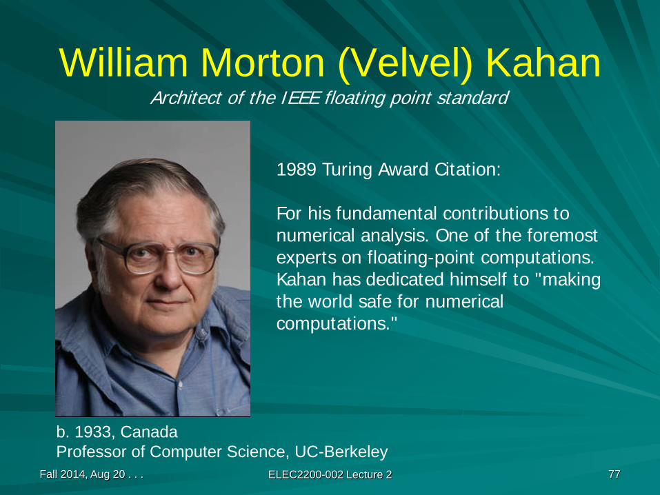
William Morton (Velvel) Kahan
1989 Turing Award Citation:
For his fundamental contributions to numerical analysis. One of the foremost experts on floating-point computations. Kahan has dedicated himself to "making the world safe for numerical computations."
Architect of the IEEE floating point standard
b. 1933, CanadaProfessor of Computer Science, UC-Berkeley

Fall 2014, Aug 20 . . . ELEC2200-002 Lecture 2 78
NegativeOverflow
PositiveOverflow
Expressible numbers
Numbers in 32-bit FormatsTwo’s complement integers
Floating point numbers
Ref: W. Stallings, Computer Organization and Architecture, Sixth Edition, Upper Saddle River, NJ: Prentice-Hall.
-231 231-10
Expressible negativenumbers
Expressible positivenumbers
0-2-127 2-127
Positive underflowNegative underflow
(2 – 2-23)×2128- (2 – 2-23)×2128
Positive zeroNegative zero + ∞– ∞
Fall 2014, Aug 20 . . . ELEC2200-002 Lecture 2 79
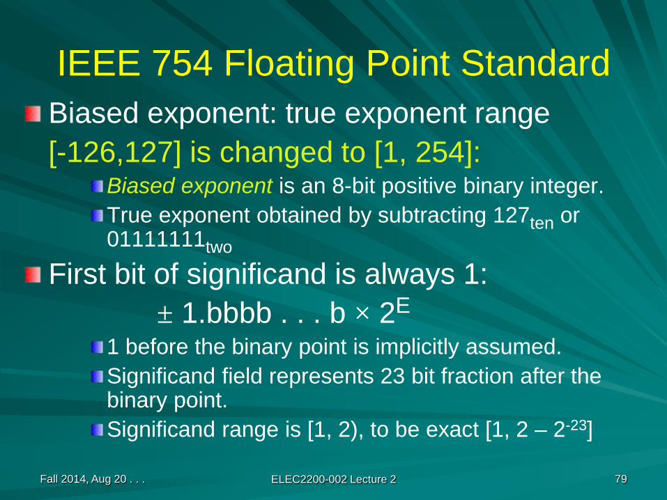
IEEE 754 Floating Point StandardBiased exponent: true exponent range[-126,127] is changed to [1, 254]:
Biased exponent is an 8-bit positive binary integer.True exponent obtained by subtracting 127ten or 01111111two
First bit of significand is always 1:± 1.bbbb . . . b × 2E
1 before the binary point is implicitly assumed.Significand field represents 23 bit fraction after the binary point.Significand range is [1, 2), to be exact [1, 2 – 2-23]

Fall 2014, Aug 20 . . . ELEC2200-002 Lecture 2 80
Examples
1.1010001 × 210100 = 0 10010011 10100010000000000000000 = 1.6328125 × 220
-1.1010001 × 210100 = 1 10010011 10100010000000000000000 = -1.6328125 × 220
1.1010001 × 2-10100 = 0 01101011 10100010000000000000000 = 1.6328125 × 2-20
-1.1010001 × 2-10100 = 1 01101011 10100010000000000000000 = -1.6328125 × 2-20
Biased exponent (0-255), bias 127 (01111111) to be subtracted
1.00.50.1250.00781251.6328125
Sign bit8-bit biased exponent
107 – 127= – 20
23-bit Fraction (F)of significand

Fall 2014, Aug 20 . . . ELEC2200-002 Lecture 2 81
Example: Conversion to Decimal
Sign bit is 1, number is negativeBiased exponent is 27+20 = 129The number is
1 10000001 01000000000000000000000
Sign bit S bits 23-30 bits 0-22normalized E F
(-1)S × (1 + F) × 2(exponent – bias) = (-1)1 × (1 + F) × 2(129 – 127)
= - 1 × 1.25 × 22
= - 1.25 × 4= - 5.0
Fall 2014, Aug 20 . . . ELEC2200-002 Lecture 2 82
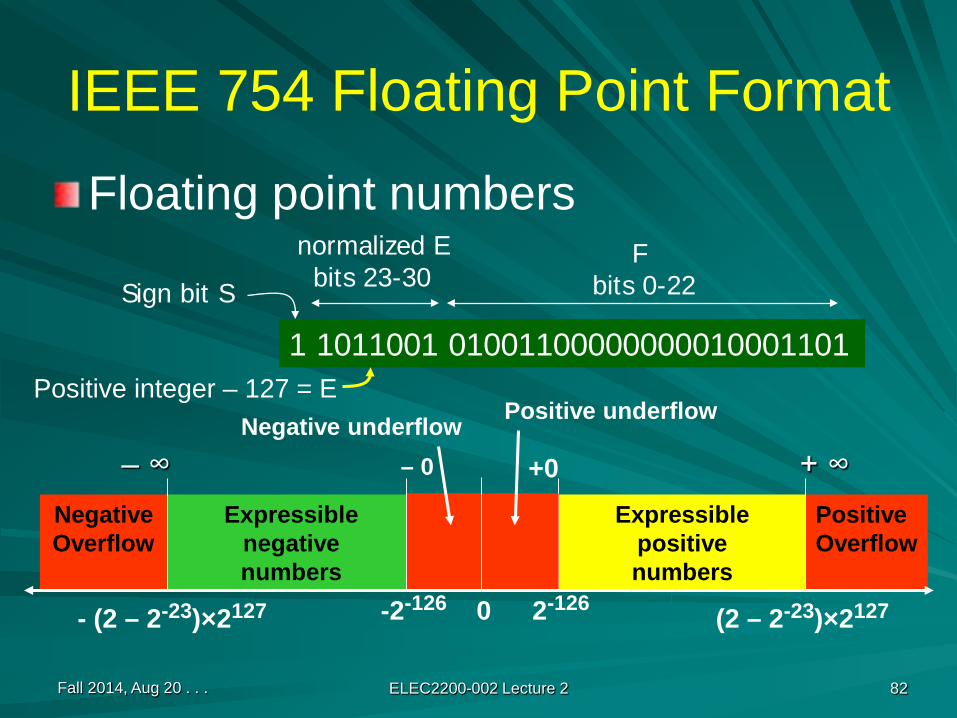
NegativeOverflow
PositiveOverflow
IEEE 754 Floating Point Format
Floating point numbers
Expressible negativenumbers
Expressible positivenumbers
0-2-126 2-126
Positive underflowNegative underflow
(2 – 2-23)×2127- (2 – 2-23)×2127
+ ∞– ∞
1 1011001 01001100000000010001101
Sign bit S bits 23-30 bits 0-22normalized E F
Positive integer – 127 = E
+0– 0
Fall 2014, Aug 20 . . . ELEC2200-002 Lecture 2 83
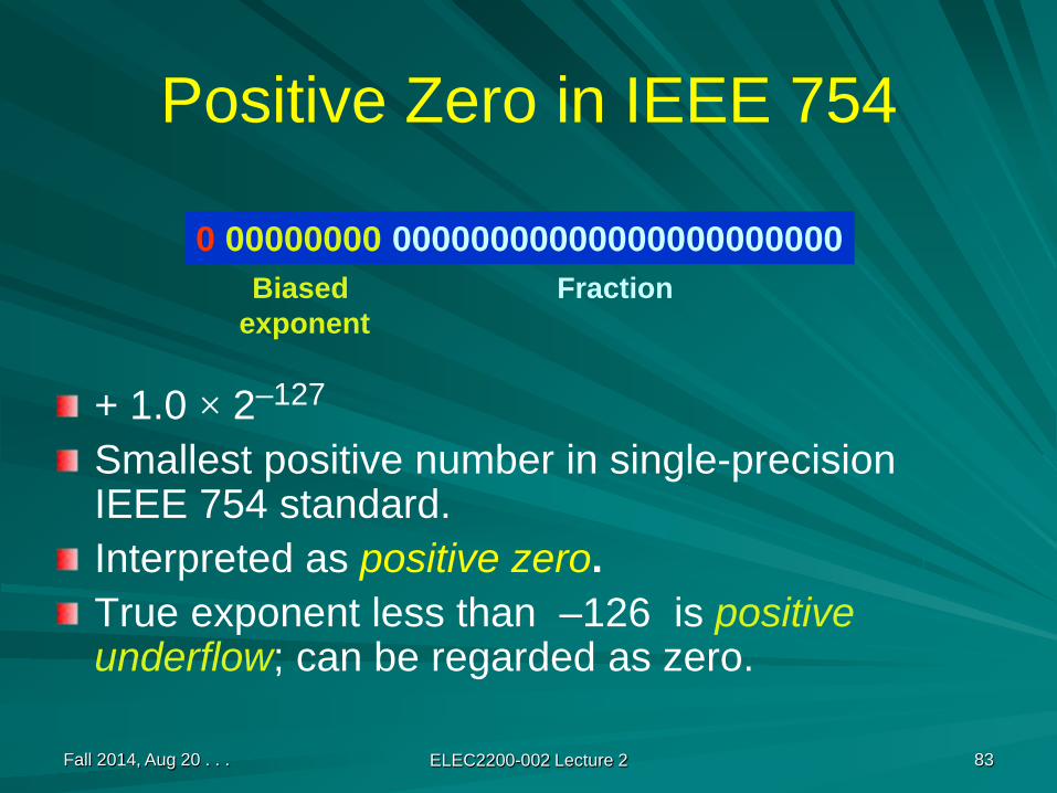
Positive Zero in IEEE 754
+ 1.0 × 2–127
Smallest positive number in single-precision IEEE 754 standard.Interpreted as positive zero.True exponent less than –126 is positive underflow; can be regarded as zero.
0 00000000 00000000000000000000000Biased
exponentFraction
Fall 2014, Aug 20 . . . ELEC2200-002 Lecture 2 84
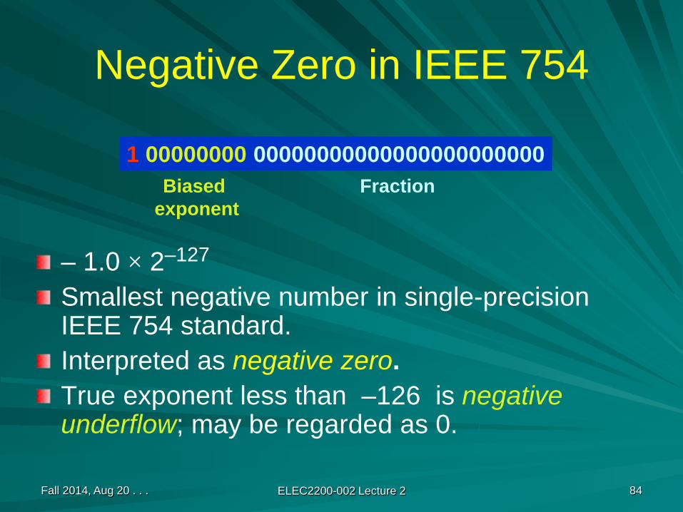
Negative Zero in IEEE 754
– 1.0 × 2–127
Smallest negative number in single-precision IEEE 754 standard.Interpreted as negative zero.True exponent less than –126 is negative underflow; may be regarded as 0.
1 00000000 00000000000000000000000Biased
exponentFraction

Fall 2014, Aug 20 . . . ELEC2200-002 Lecture 2 85
Positive Infinity in IEEE 754
+ 1.0 × 2128
Largest positive number in single-precision IEEE 754 standard.Interpreted as + ∞If true exponent = 128 and fraction ≠ 0, then the number is greater than ∞. It is called “not a number” or NaN and may be interpreted as ∞.
0 11111111 00000000000000000000000Biased
exponentFraction

Fall 2014, Aug 20 . . . ELEC2200-002 Lecture 2 86
Negative Infinity in IEEE 754
–1.0 × 2128
Smallest negative number in single-precision IEEE 754 standard.Interpreted as - ∞If true exponent = 128 and fraction ≠ 0, then the number is less than - ∞. It is called “not a number” or NaN and may be interpreted as - ∞.
1 11111111 00000000000000000000000Biased
exponentFraction
Fall 2014, Aug 20 . . . ELEC2200-002 Lecture 2 87
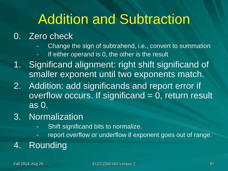
Addition and Subtraction0. Zero check
- Change the sign of subtrahend, i.e., convert to summation- If either operand is 0, the other is the result
1. Significand alignment: right shift significand of smaller exponent until two exponents match.
2. Addition: add significands and report error if overflow occurs. If significand = 0, return result as 0.
3. Normalization- Shift significand bits to normalize.- report overflow or underflow if exponent goes out of range.
4. Rounding

Fall 2014, Aug 20 . . . ELEC2200-002 Lecture 2 88
Example (4 Significant Fraction Bits)Subtraction: 0.5ten – 0.4375tenStep 0: Floating point numbers to be added
1.000two× 2 –1 and –1.110two× 2 –2
Step 1: Significand of lesser exponent is shifted right until exponents match–1.110two× 2 –2 → – 0.111two× 2 –1
Step 2: Add significands, 1.000two + ( – 0.111two)Result is 0.001two × 2 –101000
+1100100001
2’s complement addition, one bit added for sign
Fall 2014, Aug 20 . . . ELEC2200-002 Lecture 2 89
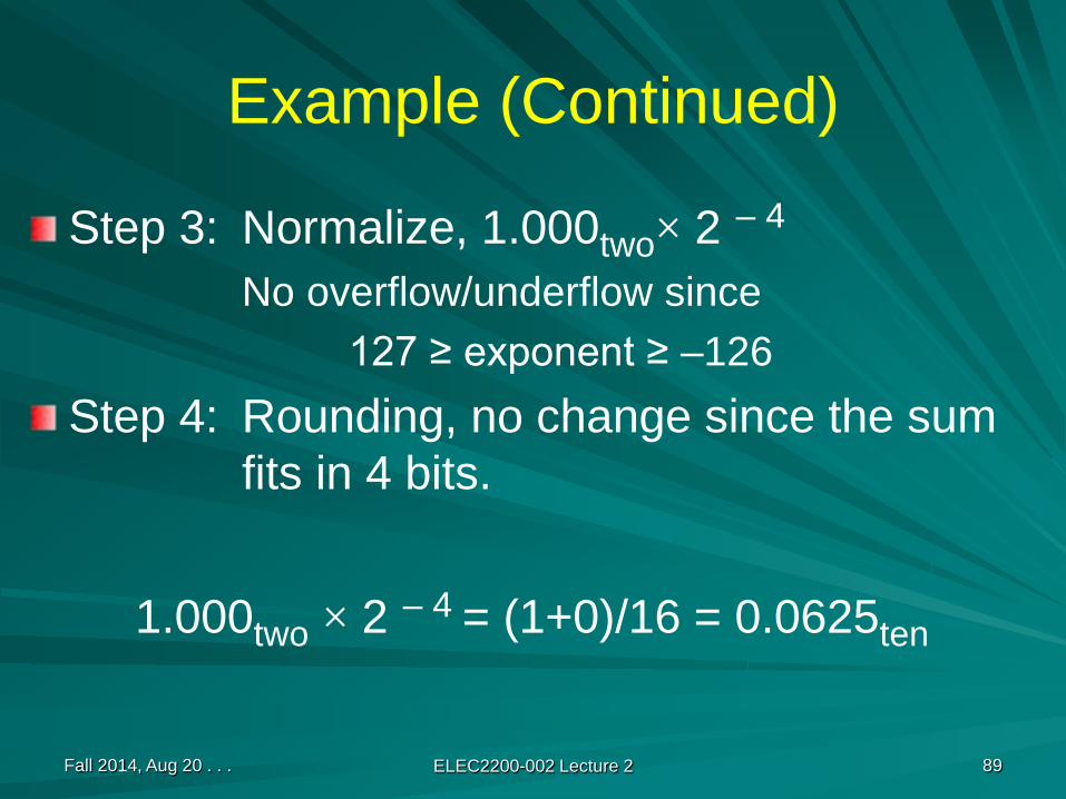
Example (Continued)
Step 3: Normalize, 1.000two× 2 – 4
No overflow/underflow since127 ≥ exponent ≥ –126
Step 4: Rounding, no change since the sum fits in 4 bits.
1.000two × 2 – 4 = (1+0)/16 = 0.0625ten

Fall 2014, Aug 20 . . . ELEC2200-002 Lecture 2 90
FP Multiplication: Basic Idea
1. Separate sign2. Add exponents (integer addition)3. Multiply significands (integer multiplication)4. Normalize, round, check overflow/underflow5. Replace sign
Fall 2014, Aug 20 . . . ELEC2200-002 Lecture 2 91
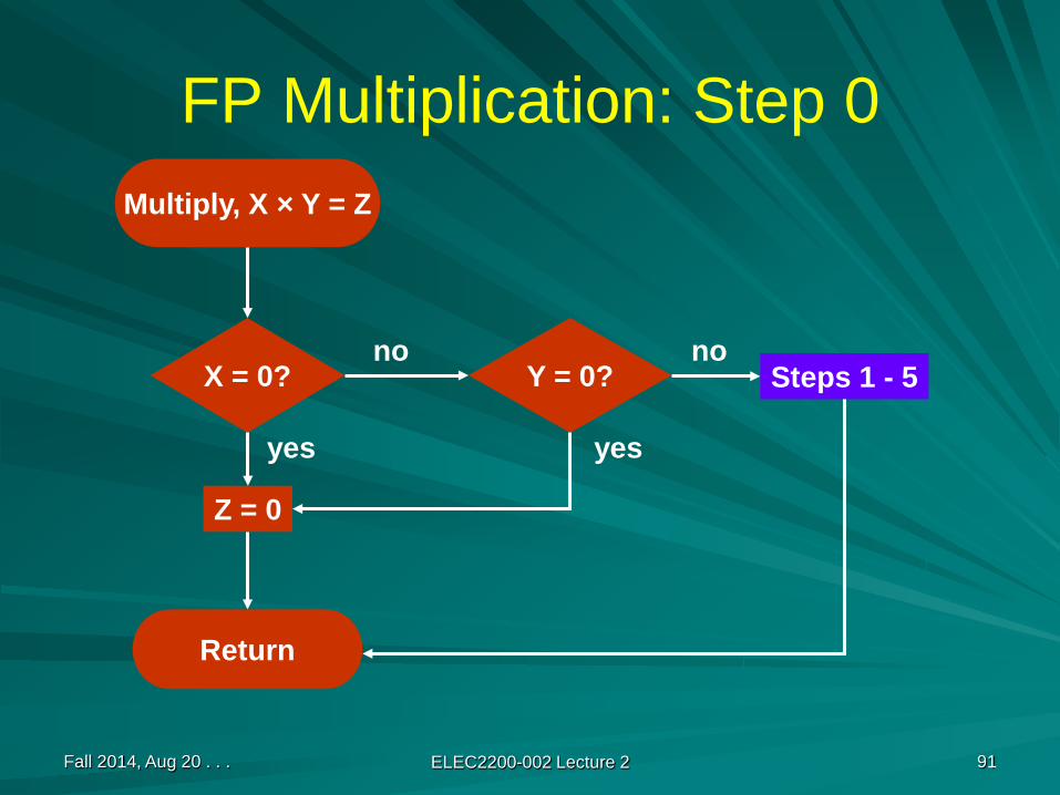
FP Multiplication: Step 0Multiply, X × Y = Z
X = 0? Y = 0?
Z = 0
Return
Steps 1 - 5
yes
no
yes
no
Fall 2014, Aug 20 . . . ELEC2200-002 Lecture 2 92
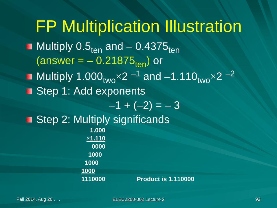
FP Multiplication IllustrationMultiply 0.5ten and – 0.4375ten(answer = – 0.21875ten) orMultiply 1.000two×2 –1 and –1.110two×2 –2
Step 1: Add exponents–1 + (–2) = – 3
Step 2: Multiply significands1.000
×1.1100000
10001000
10001110000 Product is 1.110000

Fall 2014, Aug 20 . . . ELEC2200-002 Lecture 2 93
FP Mult. Illustration (Cont.)Step 3:– Normalization: If necessary, shift significand right and
increment exponent.Normalized product is 1.110000 × 2 –3
– Check overflow/underflow: 127 ≥ exponent ≥ –126
Step 4: Rounding: 1.110 × 2 –3
Step 5: Sign: Operands have opposite signs,Product is –1.110 × 2 –3
(Decimal value = – (1+0.5+0.25)/8 = – 0.21875ten)

Fall 2014, Aug 20 . . . ELEC2200-002 Lecture 2 94
FP Division: Basic Idea
Separate sign.Check for zeros and infinity.Subtract exponents.Divide significands.Normalize and detect overflow/underflow.Perform rounding.Replace sign.
Related Documents