ELE B7 Power Systems Engineering ELE B7 Power Systems Engineering Power Flow Power Flow - - Introduction Introduction

Welcome message from author
This document is posted to help you gain knowledge. Please leave a comment to let me know what you think about it! Share it to your friends and learn new things together.
Transcript

ELE B7 Power Systems Engineering ELE B7 Power Systems Engineering
Power FlowPower Flow-- IntroductionIntroduction

Slide # 2
Dr. A.M. GaoudaUAE UniversityELEC572, 04/05
Dr. A.M. GaoudaUAE UniversityELEC572, 04/05
Dr. A.M. GaoudaUAE UniversityELEC572, 04/05
Dr. A.M. GaoudaUAE UniversityELEC572, 04/05
Dr. A.M. GaoudaUAE UniversityELEC572, 04/05
Dr. A.M. GaoudaUAE UniversityELEC572, 04/05
Dr. A.M. GaoudaUAE UniversityELEC572, 04/05
Dr. A.M. GaoudaUAE UniversityELEC572, 04/05
Dr. A.M. GaoudaUAE UniversityELEC572, 04/05
Dr. A.M. GaoudaUAE UniversityELEC572, 04/05
Dr. A.M. GaoudaUAE UniversityELEC572, 04/05
Dr. A.M. GaoudaUAE UniversityELEC572, 04/05
Dr. A.M. GaoudaUAE UniversityELEC572, 04/05
For the network shown, there are some buses connected with the generators and other buses are connected to the loads.
The Real and Reactive power is known at each Load bus. The Generator Voltages are Also Specified at the generator buses.
Introduction to Load Flow Analysis
The Transmission Lines interconnecting the buses have resistance and inductance. Therefore, the Electric Current flowing through the lines results in Electrical Losses.The Generators in the System Must supply the Total Electrical Loads pulse the Electrical Losses.
The power flow is the backbone of the power system operation, analysis and design. It is necessary for planning, operation, economic scheduling and exchange power between utilities.
The power flow is also required for many other applications such as short-circuit calculations, transient stability and contingency analysis.
G
GG
G

Slide # 3
Dr. A.M. GaoudaUAE UniversityELEC572, 04/05
Dr. A.M. GaoudaUAE UniversityELEC572, 04/05
Dr. A.M. GaoudaUAE UniversityELEC572, 04/05
Dr. A.M. GaoudaUAE UniversityELEC572, 04/05
Dr. A.M. GaoudaUAE UniversityELEC572, 04/05
Dr. A.M. GaoudaUAE UniversityELEC572, 04/05
Dr. A.M. GaoudaUAE UniversityELEC572, 04/05
Dr. A.M. GaoudaUAE UniversityELEC572, 04/05
Dr. A.M. GaoudaUAE UniversityELEC572, 04/05
Dr. A.M. GaoudaUAE UniversityELEC572, 04/05
Dr. A.M. GaoudaUAE UniversityELEC572, 04/05
Dr. A.M. GaoudaUAE UniversityELEC572, 04/05
Dr. A.M. GaoudaUAE UniversityELEC572, 04/05
There are some constrains should be considered while running the system:
In Case ofAn Equipment Over-Loaded Or Voltage-Limit Violation.
The Generation Schedule have to be adjusted and Power Flow in the transmission lines have to be Re-routed or Capacitor Banks have to be switched in order to bring the system into its Normal Operating Conditions.
To Satisfy all the previous requirement for a Reliable Power System Operation, Power Flow Study is a MUST. The Power flow study is an essential part in power system Operation, Planning and Design.
1. The Generators Must Operate within their Generation Capabilities.2. The Generators Must Deliver the required power at the Desired Voltage at
the Loads.3. There should be no bus voltage either above or below the specified Voltage
operating limits.4. There Should be no Over-Loading of equipment, including Transmission
Lines and Transformers

Slide # 4
Dr. A.M. GaoudaUAE UniversityELEC572, 04/05
Dr. A.M. GaoudaUAE UniversityELEC572, 04/05
Dr. A.M. GaoudaUAE UniversityELEC572, 04/05
Dr. A.M. GaoudaUAE UniversityELEC572, 04/05
Dr. A.M. GaoudaUAE UniversityELEC572, 04/05
Dr. A.M. GaoudaUAE UniversityELEC572, 04/05
Dr. A.M. GaoudaUAE UniversityELEC572, 04/05
Dr. A.M. GaoudaUAE UniversityELEC572, 04/05
Dr. A.M. GaoudaUAE UniversityELEC572, 04/05
Dr. A.M. GaoudaUAE UniversityELEC572, 04/05
Dr. A.M. GaoudaUAE UniversityELEC572, 04/05
Dr. A.M. GaoudaUAE UniversityELEC572, 04/05
Dr. A.M. GaoudaUAE UniversityELEC572, 04/05
Power Flow Concept
Consider the three-bus power system. Generators (G1 and G2 ) are connected to the first two buses and an electric load is connected to the third bus.The real and reactive power demands are known for the load bus (3). The generator voltages are also specified at bus 1 and bus 2.
G1 G2
Bus 1 Bus 2
Bus 3
G1 G2
Bus 1 Bus 2
Bus 3
The three transmission lines interconnecting the buses contain both resistance and reactance, thus currents flow through these lines results in electrical-losses.
In addition, there should be no over-loading of the power system equipments including transmission lines and transformers.
The two generators (G1 and G2 ) must jointly supply the total load requirements and the power losses in the transmission lines.
Furthermore, there should be no bus voltage either above or below specified values of the bus voltage operating limits.
The generators are constrained to operate within their power generation capabilities.The generators are also constrained to deliver the required power at the desired voltage at the customer loads.

Slide # 5
It is clear that the set of equations are nonlinear and the solution (bus voltages) can only obtained by iterative techniques
Consider the above circuit, if all the components and loads are expressed in terms of constant power loads (i.e., in power systems, powers are known rather than currents), then the equation to be solved are given by
*
*
VSI
IVY
Power Flow Analysis

Slide # 6
Dr. A.M. GaoudaUAE UniversityELEC572, 04/05
Dr. A.M. GaoudaUAE UniversityELEC572
04/05
Dr. A.M. GaoudaUAE University
Dr. A.M. GaoudaUAE UniversityELEC572, 04/05
Dr. A.M. GaoudaUAE UniversityELEC572, 04/05
Dr. A.M. GaoudaUAE UniversityELEC572, 04/05
Dr. A.M. GaoudaUAE UniversityELEC572, 04/05
Dr. A.M. GaoudaUAE UniversityELEC572, 04/05
Dr. A.M. GaoudaUAE UniversityELEC572, 04/05
Dr. A.M. GaoudaUAE UniversityELEC572, 04/05
Dr. A.M. GaoudaUAE UniversityELEC572, 04/05
Dr. A.M. GaoudaUAE UniversityELEC572, 04/05
Dr. A.M. GaoudaUAE UniversityELEC572, 04/05
Power Flow Analysis
It is the solution for the static operating condition of a power system.
The node voltage method is commonly used for the power system analysis. The formulation of the network equations results in complex linear equations in terms of node currents.
In power systems, powers are known rather than currents. Thus, resulting equations in terms of power become non-linear and must be solved by iterative techniques.
These non-linear equations are known as power flow equations or load flow equations.
The power flow programs compute the voltage magnitude and phase angle at each bus bar in the system under steady-state operation condition.
These programs use the bus-voltage data to compute the power flow in the network and the power losses for all equipment and transmission lines.

Slide # 7
What are the power flow equations?
What do you expect to get by solving the power flow equations?
How do we benefit from the solution of the power flow equations?

Slide # 8
Bus Admittance Matrix or Ybus
•
First step in solving the power flow is to formulate the bus admittance matrix, often call the Ybus
.•
The
Ybus
gives the relationships between all the bus current injections, I, and all the bus voltages, V,
I = Ybus
V•
The Ybus
is developed by applying KCL at each bus in the system to relate the bus current injections, the bus voltages, and the branch impedances and admittances

Slide # 9
Formulate the bus admittance matrix
for the network shown in the Figure. The Impedance diagram
of the system is as
indicated. Shunt elements are ignored.
The node voltage method
is commonly used for the power system analysis. Where,
Solution:
G1G1
Bus 1 Bus 2
Bus 3
G2G2
Bus 4
20.j 20.j
40.j
080.j
01.j 80.j
Impedance diagramImpedance diagram
44434241
34333231
24232221
14131211
YYYYYYYYYYYYYYYY=
4
3
2
1
VVVV
4
3
2
1
IIII
Orbusbusbus V]Y[I
Ybus Example

Slide # 10
The system can be represented in terms of its admittance elements as shown, where:
Bus 1 Bus 2
Bus 3
Bus 4
1I 2I01
y 02y
12y
13y
23y
34y
ijij Z
y 1
Admittance diagramAdmittance diagram
0101
101
.j.j
y 5212
.jy
25180
102
.j.j
y 052313
.jyy
Applying KCL
at each node (bus), then
32311222312022 VyVyV)yyy(I
31321211312011 VyVyV)yyy(I
43423213133432310 VyVyVyV)yyy(
3344340 VyVy

Slide # 11
23120222 yyyY 13120111 yyyY
34323133 yyyY
122112 yYY
3444 yY
133113 yYY
233223 yYY
0YY 2442
344334 yYY
0YY 4114
Then, the Node Voltage Equation is:
defined: and
44434241
34333231
24232221
14131211
YYYYYYYYYYYYYYYY=
4
3
2
1
VVVV
4
3
2
1
IIII
busbusbus1
busbus I]Z[I]Y[V busbusbus V]Y[I Or
5.12j5.12j005.12j5.22j0.5j0.5j
00.5j75.8j5.2j00.5j5.2j5.8j
Substituting the values, then the bus admittance matrix of the network is:
busY

Slide # 12
Ybus General Form
•
The diagonal terms, Yii
, are the self admittance terms, equal to the sum of the admittances of all devices incident to bus i.
•
The off-diagonal terms, Yij
, are equal to the negative of the sum of the admittances joining the two buses.
•
With large systems Ybus
is a sparse matrix (that is, most entries are zero)
•
Shunt terms, such as with the π-line model, only affect the diagonal terms.
Bus 1 Bus 2
Bus 3
Bus 4
1I 2I01y 02y
12y
13y 23y
34y
)y()y()0()0()y()yyy()y()y(
)0()y()yyy()y()0()y()y()yyy(
YYYYYYYYYYYYYYYY
4343
344332313231
2323210221
1312131201
44434241
34333231
24232221
14131211

Slide # 13
Two Bus System Example
1 21 1
1 1
2 2
( ) 1 12 162 0.03 0.04
12 15.9 12 1612 16 12 15.9
cYV VI V jZ j
I Vj jI Vj j

Slide # 14
Using the Ybus
1
bus
If the voltages are known then we can solve for the current injections:
If the current injections are known then we can solve for the voltages:
where is the bus impedance matr
bus
bus bus
Y V I
Y I V Z IZ ix

Slide # 15
Solving for Bus Currents
*1 1 1
For example, in previous case assume 1.0
0.8 0.2Then12 15.9 12 16 1.0 5.60 0.70
12 16 12 15.9 0.8 0.2 5.58 0.88Therefore the power injected at bus 1 is
S 1.0 (5.60
j
j j jj j j j
V I
V
*2 2 2
0.70) 5.60 0.70
(0.8 0.2) ( 5.58 0.88) 4.64 0.41
j j
S V I j j j

Slide # 16
Solving for Bus Voltages
1
*1 1 1
For example, in previous case assume 5.04.8
Then
12 15.9 12 16 5.0 0.0738 0.90212 16 12 15.9 4.8 0.0738 1.098
Therefore the power injected is
S (0.0738 0.902) 5 0
j j jj j j
V I j
I
*2 2 2
.37 4.51
( 0.0738 1.098) ( 4.8) 0.35 5.27
j
S V I j j

Slide # 17
Power Flow Analysis
•
When analyzing power systems we know neither the complex bus voltages nor the complex current injections
•
Rather, we know the complex power being consumed by the load, and the power being injected by the generators plus their voltage magnitudes
•
Therefore we can not directly use the Ybus
equations, but rather must use the power balance equations
*
*
VSI
IVY

Slide # 18
Definitions:The starting point is the single line diagram from which the input data can be obtained. The input data: Bus data, transmission line data and transformer data
As shown, 4 variables are associated with each bus k: the voltage magnitude Vk
, phase angle δk , net power Pk
and reactive power Qk
.
At each bus, two of these variables are specified as input data and the other two are unknowns to computed by the power flow analysis
Power Flow Analysis , cont’d

Slide # 19
Power Balance Equations
1
bus
1
From KCL we know at each bus i in an n bus systemthe current injection, , must be equal to the currentthat flows into the network
Since = we also know
i
n
i Gi Di ikk
n
i Gi Di ik kk
I
I I I I
I I I Y V
I Y V
*iThe network power injection is then S i iV I

Slide # 20
Power Balance Equations, cont’d
** * *
i1 1
S
This is an equation with complex numbers. Sometimes we would like an equivalent set of realpower equations. These can be derived by defining
n n
i i i ik k i ik kk k
ik ik ik
i
V I V Y V V Y V
Y G jB
V
jRecall e cos sin
iji i i
ik i k
V e V
j
=
=
=

Slide # 21
Real Power Balance Equations
* *i
1 1
1
i1
i1
S ( )
(cos sin )( )
Resolving into the real and imaginary parts
P ( cos sin )
Q ( sin cos
ikn n
ji i i ik k i k ik ik
k kn
i k ik ik ik ikk
n
i k ik ik ik ik Gi Dikn
i k ik ik ik ik
P jQ V Y V V V e G jB
V V j G jB
V V G B P P
V V G B
)k Gi DiQ Q

Slide # 22
Power Flow Requires Iterative Solution
i
bus
** * *
i1 1
In the power flow we assume we know S and the. We would like to solve for the V's. The problem
is the below equation has no closed form solution:
S
Rath
n n
i i i ik k i ik kk k
V I V Y V V Y V
Y
er, we must pursue an iterative approach.

Slide # 23
Gauss Iteration
There are a number of different iterative methodswe can use. We'll consider two: Gauss and Newton.
With the Gauss method we need to rewrite our equation in an implicit form: x = h(x)
To iterate we fir (0)
( +1) ( )
st make an initial guess of x, x ,
and then iteratively solve x ( ) until wefind a "fixed point", x, such that x (x).ˆ ˆ ˆ
v vh xh

Slide # 24
Gauss Iteration Example
( 1) ( )
(0)
( ) ( )
Example: Solve - 1 0
1
Let k = 0 and arbitrarily guess x 1 and solve
0 1 5 2.611851 2 6 2.616122 2.41421 7 2.617443 2.55538 8 2.617854 2.59805 9 2.61798
v v
v v
x x
x x
k x k x

Slide # 25
Stopping Criteria
( ) ( ) ( 1) ( )
A key problem to address is when to stop the iteration. With the Guass iteration we stop when
with
If x is a scalar this is clear, but if x is a vector weneed to generalize t
v v v vx x x x
( )
2i2
1
he absolute value by using a norm
Two common norms are the Euclidean & infinity
max x
vj
n
i ii
x
x
x x
=
Slide # 26
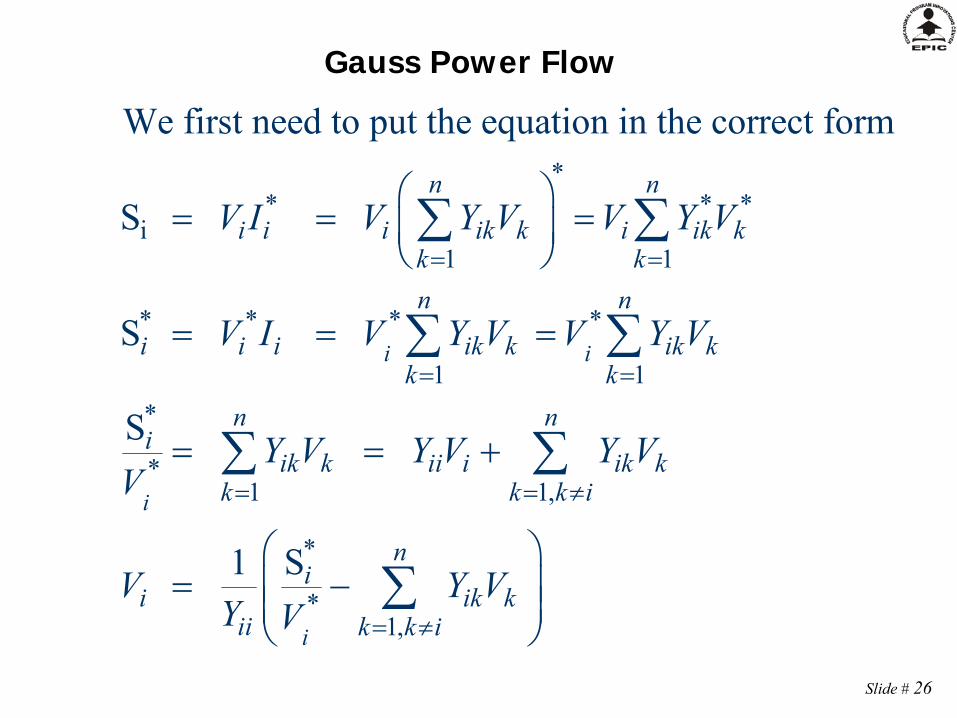
Gauss Power Flow
** * *
i1 1
* * * *
1 1*
*1 1,
*
*1,
We first need to put the equation in the correct form
S
S
S
S1
i i
i
i
n n
i i i ik k i ik kk kn n
i i i ik k ik kk k
n ni
ik k ii i ik kk k k i
ni
i ik kii k k i
V I V Y V V Y V
V I V Y V V Y V
Y V Y V Y VV
V Y VY V

Slide # 27
Gauss Two Bus Power Flow Example
A 100 MW, 50 Mvar load is connected to a generator through a line with z = 0.02 + j0.06 p.u. and line charging of 5 Mvar on each end (100 MVA base). Also, there is a 25 Mvar capacitor at bus 2. If the generator voltage is 1.0 p.u., what is V2
?

Slide # 28
Gauss Two Bus Example, cont’d
2
2 bus
bus
22
The unknown is the complex load voltage, V .To determine V we need to know the .
1 5 150.02 0.06
5 14.95 5 15Hence
5 15 5 14.70( Note - 15 0.05 0.25)
jj
j jj j
B j j j
Y
Y

Slide # 29
Gauss Two Bus Example, cont’d
*2
2 *22 1,2
2 *2
(0)2
( ) ( )2 2
1 S
1 -1 0.5 ( 5 15)(1.0 0)5 14.70
Guess 1.0 0 (this is known as a flat start)
0 1.000 0.000 3 0.9622 0.05561 0.9671 0.0568 4 0.9622 0.05562 0
n
ik kk k i
v v
V Y VY V
jV jj V
V
v V v Vj jj j
.9624 0.0553j
−1+j0.5

Slide # 30
Gauss Two Bus Example, cont’d
2
* *1 1 11 1 12 2
1
0.9622 0.0556 0.9638 3.3Once the voltages are known all other values can be determined, such as the generator powers and theline flows
S ( ) 1.023 0.239In actual units P 102.3 MW
V j
V Y V Y V j
1
22
, Q 23.9 Mvar
The capacitor is supplying V 25 23.2 Mvar

Slide # 31
Slack Bus
•
In previous example we specified S2
and V1
and then solved for S1
and V2
. •
We can not arbitrarily specify S at all buses because total generation must equal total load + total losses
•
We also need an angle reference bus.•
To solve these problems we define one bus as the "slack" bus. This bus has a fixed voltage magnitude and angle, and a varying real/reactive power injection.

Slide # 32
Gauss with Many Bus Systems
*( )( 1)
( )*1,
( ) ( ) ( )1 2
( 1)
With multiple bus systems we could calculate new V ' as follows:
S1
( , ,..., )
But after we've determined we have a betterestimate of
i
i
nvv i
i ik kvii k k i
v v vi n
vi
s
V Y VY V
h V V V
V
its voltage , so it makes sense to use thisnew value. This approach is known as theGauss-Seidel iteration.

Slide # 33
Gauss-Seidel Iteration
( 1) ( ) ( ) ( )2 12 2 3
( 1) ( 1) ( ) ( )2 13 2 3
( 1) ( 1) ( 1) ( ) ( )2 14 2 3 4
( 1) ( 1) ( 1)( 1) ( )2 1 2 3 4
Immediately use the new voltage estimates:
( , , , , )
( , , , , )
( , , , , )
( , , , ,
v v v vn
v v v vn
v v v v vn
v v vv vn n
V h V V V V
V h V V V V
V h V V V V V
V h V V V V V
)The Gauss-Seidel works better than the Gauss, andis actually easier to implement. It is used insteadof Gauss.
Slide # 34
Three Types of Power Flow Buses
•
There are three main types of power flow buses–
Load (PQ) at which P/Q are fixed; iteration solves for voltage magnitude and angle.
–
Slack at which the voltage magnitude and angle are fixed; iteration solves for P/Q injections
–
Generator (PV) at which P and |V| are fixed; iteration solves for voltage angle and Q injection
•
special coding is needed to include PV buses in the Gauss-Seidel iteration

Slide # 35
Each bus i
can be categorized into one of the following:
1. Load Bus: Input data: Pk
and QkOutput (solution): Vk
and δkLoad Bus with no generation: Pk
=
PLkQk
=
QLk
(inductive) ; Qk
= +QLk
(capacitive)
3. Voltage Controlled Bus: Generators, Switched shunt capacitors, static var
systemsInput data: Pk
,Vk , QkGmax
and QkGmin
Output (solution): Qk
and δk
2. Swing (Reference) Bus: Only one swing bus (bus #1)input data: V1
∟δ1
= 1.0∟0o
Output (solution): P1
and Q1
Three Types of Power Flow Buses

Slide # 36
Assuming a power system has n buses, then; one bus will be considered as a slack bus and the other buses are load buses (PQ-buses) and voltage controlled buses (PV-buses). Let the system buses be numbered as:
busSalcki 1
busesPVmi ,.....,3,2
busesPQnmmi ,......,2,1
For the voltage controlled buses,
unknownareandQknownareVandP iiii &||
Specifiedii |V||V|
,maxii,mini QQQ
The second requirement for the voltage controlled bus may be violated if the bus voltage becomes too high or too small. It is to be noted that we can control the bus voltage by controlling the bus reactive power.
Inclusion of PV Buses in G-S

Slide # 37
Therefore, during any iteration, if the PV-bus reactive power violates its limits then set it according to the following rule.
,maxii,maxii QQsetQQ
,minii,minii QQsetQQ
And treat this bus as PQ-bus.
unknownareθand||V&
knownareQandP
busPQForNOTE
ii
ii
,maxii,mini QQQ

Slide # 38
iininiiiiiin
kkikii jQPVYVYVYVYVVYVS
).........( 2211
*
1
**
To solve for Vi
at PV buses, we must first make a guess of Qi
b. Check Qiv+1 to see if it is within the limits
max,min, iii QQQ
Case 1: If the reactive power limits are not violated, calculate 1v
iV•
Use the most
updated value of Qi to calculate Si .
•
New Voltage magnitude and
angle are obtained
n
k
vkik
vi
vi VYVQ
1
)(*)()( Im
)()(useweiteration,thein vii
vi jQPS
Load flow solution when PV buses are present
a. Find Qi
n
kik
vkikv
i
vi
ii
vi VY
VS
YV
1,
)(*)(
*)()1( 1

Slide # 39
Speciiv
i VV |||| 1
11 || viSpecii
vi VV
Reset the magnitude Voltage magnitude is known for PV bus, therefore the new calculated
magnitude will not be used.
Only the calculated angle will be updated and used.
Use 1|| vispecii andV For the PV-bus voltage.
Case 2: If the reactive power limits are violated,
1viV
max,1
max,1
ivii
vi QQsetQQ
min,1
min,1
ivii
vi QQsetQQ
Consider this bus as a PQ-Bus, calculate bus voltage
111 || vi
vi
vi VV
The PV-bus becomes PQ-bus and both Voltage magnitude and angle are calculated and
used
Or
n
kik
vkikv
i
vi
ii
vi VY
VS
YV
1,
)(*)(
*)()1( 1

Slide # 40
EXAMPLE:
Each line has an impedance of 0.05+j0.15
1
2
2
3
1
4
2
3
4
4
5
5
0.0500
0.0500
0.0500
0.0500
0.0500
0.0500
0.1500
0.1500
0.1500
0.1500
0.1500
0.1500
FromBus
ToBus R X
Line Data for the 5 buses Network
Bus Data for the the 5 buses Network Before load flow solution
1
2
3
4
5
Slack
PV
PQ
PQ
PQ
1.0200
1.0200
?
?
?
0
?
?
?
?
100
0
50
50
50
50
0
20
20
20
?
200
0
0
0
?
?
0
0
0
0
20
0
0
0
0
0
0
0
0
BusNo.
Buscode
VoltMag.
VoltAngle
Load MW Load
MVARGen.MW
Gen.MVAR
QMin.
QMax.
InjectMVAR
0
60
0
0
0
The shunt admittance is neglected
5
1
2
3 4
G1G2
Slide # 41
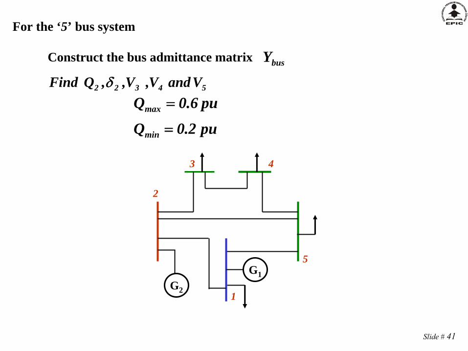
busY
For the ‘5’ bus system
Construct the bus admittance matrix
54322 VandV,V,,QFind
pu2.0Q
pu6.0Q
min
max
5
1
2
3 4
G1G2

Slide # 42
5
1
2
3 4
G1G2
Ybus Construction
6j215.0j05.0
1z1y
12j4yyY 151211
18j6yyyY 25232122
12j4yyY 343233
12j4yyY 454344
18j6yyyY 54525155
6j2yY 1212
6j2yY 1515
0YY 1413
SOLUTION:
busY4.0 - J12.0 -2.0 + J6.0 0 0 -2.0 + J6.0-2.0 + J6.0 6.0 -J18.0 -2.0 + J6.0 0 -2.0 + J6.0
0 -2.0 + J6.0 4.0 -J12.0 -2.0 + J6.0 0 0 0 -2.0 + J6.0 4.0 -J12.0 -2.0 + J6.0
-2.0 + J6.0 -2.0 + J6.0 0 -2.0 + J6.0 6.0 -J18.0

Slide # 43
)QQ(j)PP(S d,2g,2d,2g,2sch,2
1
2
3
4
5
Slack
PV
PQ
PQ
PQ
1.0200
1.0200
?
?
?
0
?
?
?
?
100
0
50
50
50
50
0
20
20
20
?
200
0
0
0
?
?
0
0
0
0
20
0
0
0
0
0
0
0
0
BusNo.
Buscode
VoltMag.
VoltAngle
Load MW Load
MVARGen.MW
Gen.MVAR
QMin.
QMax.
InjectMVAR
0
60
0
0
0
1
2
3
4
5
Slack
PV
PQ
PQ
PQ
1.0200
1.0200
?
?
?
0
?
?
?
?
100
0
50
50
50
50
0
20
20
20
?
200
0
0
0
?
?
0
0
0
0
20
0
0
0
0
0
0
0
0
BusNo.
Buscode
VoltMag.
VoltAngle
Load MW Load
MVARGen.MW
Gen.MVAR
QMin.
QMax.
InjectMVAR
0
60
0
0
0
)0Q(j)00.2(S g,2sch,2
)2.00(j)5.00(S sch,3
2.0j5.0S sch,4
2.0j5.0S sch,3
2.0j5.0S sch,5
)QQ(j)PP(S d,1g,1d,1g,1sch,1
)5.0Q(j)0.1P(S g,1g,1sch,1
The net scheduled power injected at each bus is:
5
1
2
3 4
G1G1G2

Slide # 44
The bus admittance matrix is
Using GS method, select the initial values for the unknowns as:
oo5
o4
o3 01VVV
4.0 - J12.0 -2.0 + J6.0 0 0 -2.0 + J6.0-2.0 + J6.0 6.0 -J18.0 -2.0 + J6.0 0 -2.0 + J6.0
0 -2.0 + J6.0 4.0 -J12.0 -2.0 + J6.0 0 0 0 -2.0 + J6.0 4.0 -J12.0 -2.0 + J6.0
-2.0 + J6.0 -2.0 + J6.0 0 -2.0 + J6.0 6.0 -J18.0
0o2
o1 002.1V
02.1|V| spec2
The known values are:
)VY...VY......VYVY(VjQP niniii22i11i*iii
and
Check Q2 is within the limits
2.0Q ,min2 6.0Q ,max2 and
,max22,min2 QQQ
Start the first iteration
)}VYVYVYVYVY(VIm{Q o525
o424
o323
o222121
*2
12
2448.0Q12
Bus 2 is PV Bus

Slide # 45
6.02448.020.0.;e.iQQQ ,max22,min2
The reactive power limits are not violated, Calculate:
22
222 Y
jQPK
22
2121 Y
YL 22
2323 Y
YL
o525
o424
o323121*o
2
212 VLVLVLVL
)V(KV
K2 = 0.0456 + j0.0959 L21 = -0.3333 L23 = -0.3333
The values for Ki and Lip are computed once in the beginning and used in every iteration.
22
2424 Y
YL 22
2525 Y
YL
o5.11131.0555 12V
L24 = 0.0 L25 = -0.3333
02.1|V||V| Speci21
2 Reset the magnitude Voltage magnitude is
known and fixed for a PV bus, therefore the
new calculated magnitude will not be
used.
o12 1113.5
o5.11131.02 12V
Therefore,
2448.0j0.2S sch,2

Slide # 46
o535
o434
1232131*o
3
313 VLVLVLVL
)V(KV
44
444 Y
jQPK
44
4141 Y
YL 44
4242 Y
YL
K3 = -0.0275 - j0.0325 L31 = 0.0 L32 = -0.5000
o0.75590.9806 13V
L34 = -0.5000 L35 = 0.0
Bus 3 is PQ Bus
33
3434 Y
YL 33
3535 Y
YL
o545
1343
1242141*o
4
414 VLVLVLVL
)V(KV
33
333 Y
jQPK
33
3131 Y
YL 33
3232 Y
YL
K4 = -0.0275 - j0.0325 L41 = 0.0 L42 = 0.0
o1.5489-0.9631 14V
L43 = -0.5000 L45 = -0.5000
Bus 4 is PQ Bus
44
4343 Y
YL 44
4545 Y
YL

Slide # 47
1454
3353
1252151*o
5
515 VLVLVLVL
)V(KV
K5 = -0.0183 - 0.0217i L51 = -0.3333 L52 = -0.3333
o0.0031-0.9812 15V
L53 = 0.0 L54 = -0.3333
Bus 5 is PQ Bus
Check Q2 is within the limits 6.0Q2.0 2
Start the second iteration
)}VYVYVYVYVY(VIm{Q 1525
1424
1323
1222121
*12
22
0.029022Q
Bus 2 is PV Bus
The reactive power limits are violated
2.0QQsetQQ ,mini2,mini2
And treat this bus as PQ-bus 2.0j0.2S sch,2
All Buses 2, 3, 4 and 5 are PQ Buses. Find the bus voltages using GS method
Use the most updated value of
Q2 to calculate the constant K2

Slide # 48
Accelerated G-S Convergence
( 1) ( )
( 1) ( ) ( ) ( )
(
Previously in the Gauss-Seidel method we werecalculating each value x as
( )To accelerate convergence we can rewrite this as
( )Now introduce acceleration parameter
v v
v v v v
v
x h x
x x h x x
x
1) ( ) ( ) ( )( ( ) )With = 1 this is identical to standard gauss-seidel.Larger values of may result in faster convergence.
v v vx h x x

Slide # 49
Accelerated Convergence, cont’d
( 1) ( ) ( ) ( )
Consider the previous example: - 1 0
(1 )Comparison of results with different values of
1 1.2 1.5 20 1 1 1 11 2 2.20 2.5 32 2.4142 2.5399 2.6217 2.4643 2.5554 2.6045 2.6179 2.6754 2.59
v v v v
x x
x x x x
k
81 2.6157 2.6180 2.5965 2.6118 2.6176 2.6180 2.626

Slide # 50
Accelerated Convergence, cont’d
The Effect of Acceleration Factor
1.5≤≤1.7
Adequate Values of the Acceleration Factor:

Slide # 51
Gauss-Seidel Advantages
•
Each iteration is relatively fast (computational order is proportional to number of branches + number of buses in the system
•
Relatively easy to program

Slide # 52
Gauss-Seidel Disadvantages
•
Tends to converge relatively slowly, although this can be improved with acceleration
•
Has tendency to miss solutions, particularly on large systems
•
Tends to diverge on cases with negative branch reactances (common with compensated lines)
•
Need to program using complex numbers
Related Documents


