ELCOCoupling Flexible Compression Sleeve Coupling

Welcome message from author
This document is posted to help you gain knowledge. Please leave a comment to let me know what you think about it! Share it to your friends and learn new things together.
Transcript

ELCO�CouplingFlexible Compression Sleeve Coupling
2
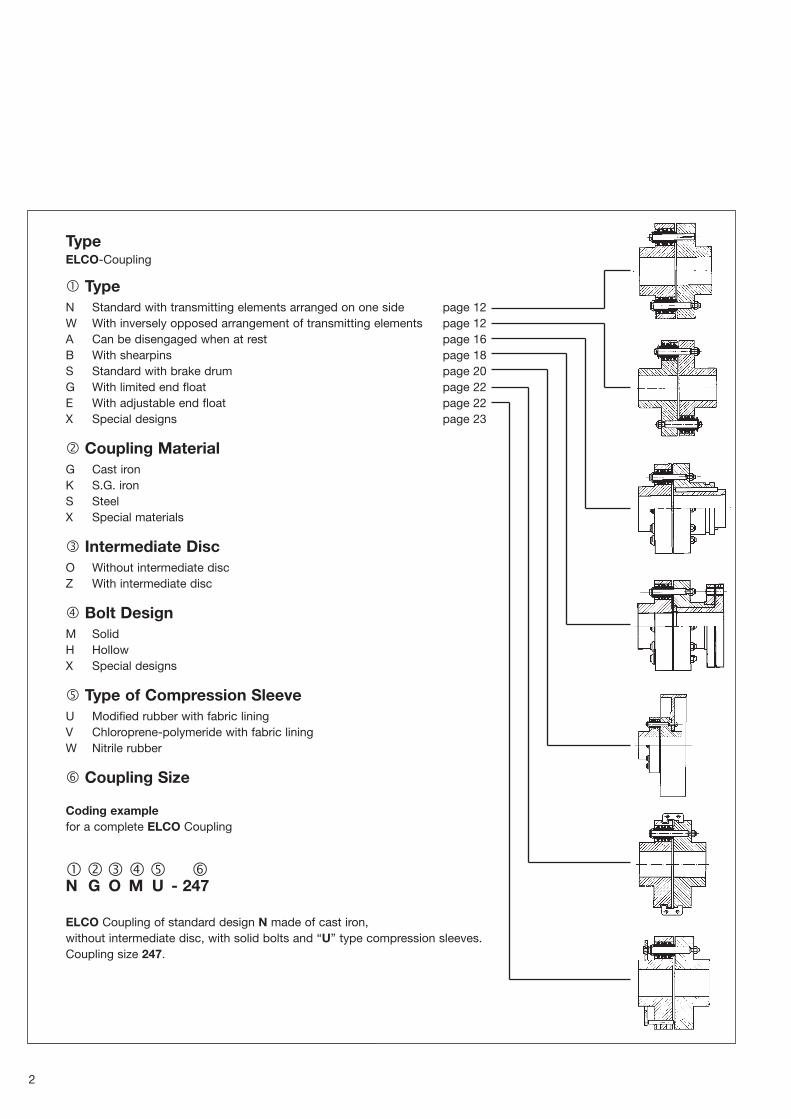
TypeELCO�Coupling
� TypeN Standard with transmitting elements arranged on one side page 12W With inversely opposed arrangement of transmitting elements page 12A Can be disengaged when at rest page 16B With shearpins page 18S Standard with brake drum page 20G With limited end float page 22E With adjustable end float page 22X Special designs page 23
� Coupling MaterialG Cast ironK S.G. ironS SteelX Special materials
� Intermediate DiscO Without intermediate discZ With intermediate disc
� Bolt DesignM SolidH HollowX Special designs
� Type of Compression SleeveU Modified rubber with fabric liningV Chloroprene�polymeride with fabric liningW Nitrile rubber
� Coupling Size
Coding examplefor a complete ELCO Coupling
��� �� �N G O M U � 247
ELCO Coupling of standard design N made of cast iron, without intermediate disc, with solid bolts and “U” type compression sleeves. Coupling size 247.

Contents
Technical Information 4
Design of an ELCO Coupling 5
Rating 6
Design Factors 7
Nominal Capacityof the ELCO Coupling 8
ELCO Couplings forStandard IEC Motors 10
Permissible Misalignment 11
Dimension Chart
Type N/W 12
Type A 16
Type B 18
Type S 20
Type G/E 22
Special designs 23
Weights 24
Moments of Inertia 25
Spare Parts 26
The weights given in thetables are average values andthey and the illustrations arenot strictly binding.
Alterations may be made inthe interests of technicalprogress. This technical docu�ment is protected by law(DIN 34).
Couplings used in transportand industrial service must beprovided with circumferentialreinforcement, covers orguards to comply with theaccident prevention regula�tions.
ELCO Torsionally Flexible Couplingeffectively absorbs shocksand suppresses vibrationswhich arise during operation.Moreover it takes up radialand angular misalignments ofthe connected shafts andallows a certain amount ofangular and linear misalign�ment.
The installation of a correctlyrated ELCO Coupling guaran�tees reliable transmission ofpower and offers extensiveprotection fo the connectedmachine shafts against dam�age by vibration.
The ELCO Coupling hasproved itself in tens of thou�sands of drives through itsadaptable design and itsaccurate workmanship.
The ELCO Coupling showsthe following advantages:
�� Torque and speed shockloads are diminished bythe spring action anddamping effect of the com�pression sleeves.
�� Torsional vibrations areeffectively limited by ashifting of the system’snatural frequencies in areaswhich are not critical forthe operating range.
�� Torsional vibrations areeffectively limited by thecoupling’s damping effectwhen passing through thecritical speed.
�� Safe and reliable torquetransfer results from thecoupling bolt design andfrom the axial pre�loadingof the compressionsleeves.
�� Radial and angular mis�alignments are compensat�
ed by the universal flexibili�ty of the compressionsleeves and by the easewith which they aredeformed.
�� Longitudinal displacementsof the shafts are taken upby the ability of the com�pression sleeves to moveslightly in the mating holes.
�� Axial dismantling of thecompression sleeves andcoupling bolts is trouble�free without any need forremoving the coupling orfor moving the connectedunits (for changing thesleeves or for test runsetc.)
�� Machines can be alignedwhen the coupling boltsare not in position.
3

RENK ELCO couplings ofsmaller sizes are made ofsteel exclusively; bigger sizesof cast iron or steel/cast steel,depending on speed andloadings.
The maximum speeds for bothcast iron and steel couplingsfor lads individual design typeare indicated in the charts.
The bore for the couplingbolts and sleeves are accu�rately spaced and machinedto a fine finish. The arrange�ment of all bolts in one cou�pling half offers the advantageof accomodating shaft ends oflarge�diameter.
Balancing: StaticELCO Couplings from size247 upwards with finish�machined bore, no extracharge.
Balancing: DynamicELCO Coupling size 018 to454 with finish�machinedbore, extra price to be quoted.
Dynamic balancing will bedone upon request eitherbefore or after keywaying (G =Qualities norm according toDIN ISO 1940, part 1). If cus�tomers do not request a spe�cial class of balancing bodies(G�group) with its specificspeed:
G 16is applied to all ELCO coup�lings operating within speed
Technical Information
range I. For speeds > 1500R.P.M. the same value is appli�cable as for n = 1500 R.P.M.
G 6.3is applied to all ELCO coup�lings operating within speedrange II. For speeds > 1500R.P.M. the same value is appli�cable as for n = 1500 R.P.M.
ELCO couplings with roughmachined bores can be sup�plied only unbalanced.
The torque is transmitted bymeans of coupling bolts andcompression sleeves of highgrade elastomer (fig. 1 and 2).All types of ELCO couplingsconsist essentially of couplingflanges 1 and 2. The steelcoupling bolts on which thecompression sleeves aremounted, are fitted in flange 2and engage with the holes inflange 1. Type W: the trans�mission elements are placedon both flanges of the cou�pling in alternate order.
ELCO coupling sizes 018 to129 are fitted with nonremov�able coupling bolts and canbe drawn apart, therefore, onlyin an axial direction. On theother hand, couplings fromsize 149 are provided withdetachable transmission boltswhich makes radial disman�tling possible.
The compression sleeves haveparticulary thick walls and arenormally designed with a fab�
ric lining in the bore which, incontrast to the conventionalflange coupling, means thatthe ELCO coupling has un�usually high working capacity.
Arranging the holes on thesmallest possible pitch circlediameter produces a largeangle of twist. Several groovesof differing depth around theperiphery of the sleeves causea progressive torsion charac�teristic. Because of the easewith which the compressionsleeves are deformed onlysmall reactive forces arise atthe bearings. As the magni�tude of these forces isdependent on various influ�encing factors, please ask usfor further details.
The compression sleeve isfixed to the coupling bolts bymeans of a washer and a cir�clip, and the bolts are held inthe half coupling, flange 2, bya locking nut on the end of thebolt. Any movement betweencoupling bolts and compres�sion sleeves is thus avoided.
The following compres�sion sleeves can be supplied:1. U�type CompressionSleeves(modified natural rubber) witha fabric layer vulcanised intothe bore, are used for all stan�dard drives and have alsoproved themselves for drives,
working discontinuosly andwith fluctuating torque. Theyare especially suitable formachines subjected to vibra�tions e.g. diesel engines andother reciprocating engines.
2. V�type CompressionSleeves(chloroprene polymer) with afabric layer vulcanised into thebore, are intended particularlyfor couplings which run in oilor which are exposed to oilvapours.
3. W�type CompressionSleeves(nitrile rubber) without the fab�ric layer, are used for driveswhere smaller angles of twistare required than can beachieved with the U�Type. W�Type Compression Sleeveshave a limited resistance tooil.
All types of the ELCO coup�ling can be provided with eachof these designs of compres�sion sleeve (see table on page6 for angles of twist).
The compression sleevesmust be protected againstultra�violet rays and heat, asotherwise these will changethe properties of the material.
Such influences affecting thenatural ageing change theelasticity characteristics andthe damping properties.
Fig. 1 Assembled compressions sleeve unloaded
Fig. 2 Compression sleeve under max. load
4

5
Design of an ELCO Coupling
ELCO Coupling Type E with adjustable end float Photo: Nordwestdeutsche Kraftwerk AG, Kraftwerk Wilhelmshaven
According to DIN 740 flexibleand damping couplings aredescribed as torsionally flexi�ble shaft couplings.Torsionally flexible couplingsinfluence the torsional vibra�tion behaviour of driving units.Through their use the loadingamplitudes an dthe multitudeof high loadings can be vastlydecreased during runningperiods in the torque leadingparts of driving aggregates.For stationary machines withuneven torques (i.e. pistonmachines) less stress andtherefore a more quiet run willbe achieved through displace�ment of the critical speedrange.
In conclusion the allround flex�ibility of torsionally flexible
couplings enables the balanceof radial, axial and angularshaft displacement wherebyan expensive common foun�dation for both driven anddriving machine can be avoid�ed.
The ELCO coupling serieswhich has an extremely largenominal torque from 18 Nm to540 000 Nm has proved itselfwell in many areas of drivingtechniques as an allround flex�ible coupling whose flexibleelements can be easilychanged.
Typical Applications
Coupling Speed Power ApplicationSize [R.P.M.] [kW]
335 985 1900 Cement mill
420 62 560 Conveyor belt
184 970 30 Belt drive
149 2000 15 Compressor
420 590 6300 Exhauster
271 1475 730 Centrifugal pump
454 585 7100 Generator
149 5000 17 D.C. Machine
247 1480 132 Converter
335 1800 2500 Ship’s turbo�generator
231 3600 410 Ship’s reversing gear

Rating
6
For determining the size of anELCO coupling, a first criterionis the operating factor K.To select the appropriate size,K can either be applied to thenominal torque of the couplingTKN or to the nominal powerof the coupling PKN.
TKN = TAN. K
or
PKN = PAN. K
K = SB. ST
. SS. SA
TAN = driving torquePAN = driving powerSB = load factorST = temperature factorSS = switch factorSA = factor of driving
machine
For exact calculations, consid�ering the shock load as forinstance applicable in thecase of start conditions“Technical Information No. 47”is available on request.
Coupling Max. Coupling Displacement angle ϕ [°]size speeds 1) torque static, under TKN
PAN [kW] . Ksleeve sleeve
n U and V WI II TKN[min�1] [min�1] [Nm] ψ = 0,26 ψ = 0,86
018 6000 — 18 . 100 0,0019 3,4 3,4036 36 . 100 0,0038044 6000 — 44 . 100 0,0046 3,0 3,1066 66 . 100 0,0069098 6000 — 98 . 100 0,0103 3,4 3,0113 13 . 101 0,014123 6000 — 23 . 101 0,0241 3,4 3,1129 29 . 101 0,030149 3600 5600 49 . 101 0,051 3,8 4,0161 61 . 101 0,064184 3000 5000 84 . 101 0,088 3,2 3,1210 10 . 102 0,105214 2650 4500 14 . 102 0,147 3,5 3,0215 15 . 102 0,157222 2250 4000 22 . 102 0,230 3,6 2,8228 28 . 102 0,293231 2000 3600 31 . 102 0,33 3,2 2,6237 37 . 102 0,39247 1800 3300 47 . 102 0,49 3,3 3,3259 W 59 . 102 0,62271 1650 3000 71 . 102 0,74 2,9 2,7285 W 85 . 102 0,90311 1500 2800 11 . 103 1,15 3,0 3,4314 W 14 . 103 1,47316 1250 2500 16 . 103 1,68 2,5 3,0319 W 19 . 103 2,0324 1120 2250 24 . 103 2,51 3,3 2,8329 W 29 . 103 3,04335 1000 2000 35 . 103 3,66 2,8 2,4341 W 41 . 103 4,29353 850 1750 53 . 103 5,55 2,8 2,9378 750 1500 78 . 103 8,2 2,3 2,1412 630 1300 12 . 104 12,6 2,8 2,4416 630 1300 16 . 104 16,8 2,7 2,3420 560 1200 20 . 104 20,9 2,3 1,9426 500 1050 26 . 104 27,2 3,0 2,3432 500 1050 32 . 104 33,5 2,8 2,1443 450 890 43 . 104 45,0 2,5 1,7454 400 750 54 . 104 56,5 2,2 1,3
1) For maximum speed II, from size 149 only steel couplings with hollow bolts must be used.
Proportional damping

7
Design Factors
Load factor SBDriven machine TTyyppee ooff CCoommpprreessssiioonn SSlleeeevvee
U V, W
Generators with constant power output (lighting), light lineshafts, small fans, rotary machine tools,small centrifugal pumps, flour milling machines, light textile machines, light lifts, elevators 1 � 1,1 1,5 � 1,6and other conveyors.
Auxiliary machines for ships, shears, cranes, grinding machines, heavy lifts, generators with slightlyvariable output, coilers, chain conveyors, sand blast units, textile machines, line shafting, mediumfans/blowers, large rotary machine tools, winches, centrifugal pumps, rotary pumps and compressors, 1,1 � 1,2 1,6 � 1,7smoothly running stirrers, reversible machine tools, belt conveyors, wood working machinery, ringframes, washing machines, looms.
Passenger lifts, rotary kilns, tanning barrels, paper machines large fans, cooling drums, stirrers, rollerframes, looms, brick presses, printing machines, crushing plants, sugar mill machinery, wood grinders, 1,2 � 1,3 1,8 � 1,9mine fans, ship’s propellers, draw benches.
Dredger drives, briquette presses, rubber rolling mills, coal pulverizers, piston pumps with fly wheel,reciprocating presses with light fly wheel, pug mills for sand and paper, plunger pumps, tumblers,vibrators, combination mills, cement mills, forging machines, piston and stamping presses, small 1,4 � 1,6 2,1 � 2,3ferrous rolling mills, roller tables for rolling mills.
Couching machines, horizontal saw frames, wet presses, paper calenders, rolling devices for paper,drying cylinders, heavy centrifuges, crushing machines, Turras drives. 1,7 � 1,9 2,6 � 2,8
Cold and hot rolling mills withor without flywheel, roadworking machines, weldingand frequency converters forplants subject to shock loadsand other special machines on
request. For the use of ELCOcouplings in equipment whereheavy shock loads are to beexpected, a vibration calcula�tion should be made for insta�tionary conditions. Within the
machine groups the lower val�ues are for lighter drives andthe higher values for heavierdrives. In the case of internalcombustion engines it is re�commended to calculate the
vibrations.
Temperature factor ST
compression U V Wsleeve
≤ 40°C 1 1 1
> 40 � 60°C 1,1 1,2 1,1
> 60 � 70°C 1,3 1,4 1,2
> 70 � 80°C 1,5 1,7 1,4
Shifting factor SS
s/h
< 40 1
< 80 1,1
< 120 1,2
< 120 � 360 1,3
Factor SA of driving machine
el. motor, combustion engineturbine, multi� Diesel / Otto enginecyl. internalcombustionengine 3cyl. 2cyl. 1cyl.
1 1,15 1,3 1,6

Coupling n [R.P.M.]
size
10 16 25 40 63 100 125 160 200 250 315 400 500 630 710 800 900 1000
Nominal capacity PKN [kW]1) of the coupling
018 0,019 0,030 0,048 0,076 0,12 0,19 0,24 0,30 0,38 0,48 0,60 0,76 0,95 1,20 1,35 1,52 1,71 1,90
036 0,038 0,061 0,095 0,15 0,24 0,38 0,48 0,61 0,76 0,95 1,12 1,52 1,90 2,40 2,70 3,04 3,42 3,80
044 0,046 0,074 0,12 0,18 0,29 0,46 0,58 0,74 0,92 1,15 1,45 1,84 2,30 2,90 3,27 3,68 4,14 4,60
066 0,069 0,11 0,17 0,28 0,43 0,69 0,86 1,10 1,38 1,73 2,17 2,76 3,45 4,35 4,90 5,52 6,21 6,90
098 0,11 0,17 0,26 0,42 0,66 1,05 1,31 1,68 2,10 2,63 3,31 4,20 5,25 6,62 7,46 8,40 9,45 10,5
113 0,14 0,22 0,35 0,56 0,88 1,40 1,75 2,24 2,80 3,50 4,41 5,60 7,00 8,82 9,94 11,2 12,6 14,0
123 0,24 0,38 0,59 0,94 1,48 2,35 2,94 3,76 4,70 5,88 7,40 9,40 11,8 14,8 16,7 18,8 21,2 23,5
129 0,30 0,48 0,75 1,20 1,89 3,00 3,75 4,80 6,00 7,50 9,45 12,0 15,0 18,9 21,3 24,0 27,0 30,0
149 0,52 0,83 1,30 2,08 3,28 5,20 6,50 8,32 10,4 13,0 16,4 20,8 26,0 32,8 36,9 41,6 46,8 52,0
161 0,64 1,02 1,60 2,56 4,03 6,40 8,0 10,2 12,8 16,0 20,2 25,6 32,0 40,3 45,4 51,2 57,6 64,0
184 0,89 1,43 2,23 3,56 5,61 8,90 11,1 14,3 17,8 22,3 28,0 35,6 44,5 56,1 63,2 71,2 80,1 89,0
210 1,05 1,68 2,63 4,20 6,62 10,5 13,1 16,8 21,0 26,3 33,1 42,0 52,5 66,2 74,6 84,0 94,5 105
214 1,47 2,35 3,68 5,88 9,26 14,7 18,4 23,5 29,4 36,8 46,3 58,8 73,5 92,6 104 118 132 147
215 1,57 2,51 3,93 6,28 9,89 15,7 19,6 25,1 31,4 39,3 49,5 62,8 78,5 98,9 111 126 141 157
222 2,21 3,54 5,53 8,84 13,9 22,1 27,8 35,4 44,2 55,3 69,6 88,4 111 139 157 177 199 221
228 2,93 4,69 7,33 11,7 18,5 29,3 36,6 46,9 58,6 73,3 92,3 117 147 185 208 234 264 293
231 3,30 5,28 8,25 13,2 20,8 33,0 41,3 52,8 66,0 82,5 104 132 165 208 234 264 297 330
237 3,90 6,24 9,75 15,6 24,6 39,0 48,8 62,4 78,0 97,5 123 156 195 246 277 312 351 390
247 4,90 7,84 12,3 19,6 30,9 49,0 61,3 78,4 98,0 123 154 196 245 309 348 392 441 490
259 W 6,20 9,92 15,5 24,8 39,1 62,0 77,5 99,2 124 155 195 248 310 391 440 496 558 620
271 7,40 11,8 18,5 29,6 46,6 74,0 92,5 118 148 185 233 296 370 466 525 592 666 740
285 W 9,0 14,4 22,5 36,0 56,7 90,0 113 144 180 225 284 360 450 567 639 720 810 900
311 11,0 17,6 27,5 44,0 69,3 110 138 176 220 275 347 440 550 693 781 880 990 1100
314 W 14,7 23,5 36,8 58,8 92,6 147 184 235 294 368 463 588 735 926 1044 1176 1323 1470
316 16,3 26,1 40,8 65,2 103 163 204 261 326 408 513 652 815 1030 1157 1304 1467 1630
319 W 20,0 32,0 50,0 80,0 126 200 250 320 400 500 630 800 1000 1260 1420 1600 1800 2000
324 25,1 40,2 62,8 100 158 251 314 402 502 628 791 1000 1255 1580 1782 2000 2260 2510
329 W 30,4 48,6 75,9 122 191 304 380 486 607 759 957 1215 1518 1913 2156 2429 2732 3036
335 36,6 58,6 91,5 146 231 366 458 586 732 915 1153 1460 1830 2310 2600 2930 3295 3660
341 W 42,9 68,7 107 172 281 429 537 687 859 1073 1352 1717 2146 2704 3048 3434 3863 4293
353 55,5 88,8 139 222 350 555 694 888 1110 1390 1750 2220 2775 3500 3940 4440 4995 5550
378 82,7 132 207 331 521 827 1034 1320 1654 2070 2605 3310 4135 5210 5870 6615 7445 8270
412 120 192 300 480 756 1200 1500 1920 2400 3000 3780 4800 6000 7560 8520 9600 10800 12000
416 165 264 412 660 1040 1650 2060 2640 3300 4120 5200 6600 8250 10400 11710 13200 14850 16500
420 209 334 522 835 1317 2090 2610 3340 4180 5225 6580 8360 10450 13160 14850 16720 18800 20900
426 270 432 675 1080 1700 2700 3380 4320 5400 6750 8500 10800 13500 17000 19200 21600 24300 27000
432 337 540 840 1350 2120 3370 4220 5400 6740 8440 10600 13480 16880 21200 23900 26960 30300 33700
443 450 720 1125 1800 2830 4500 5630 7200 9000 11260 14200 18000 22520 28400 32000 36000 40500 —
454 562 900 1400 2250 3540 5620 7025 9000 11240 14050 17700 22480 28100 35400 39900 44960 50500 —
Nominal Capacity PKN of the ELCO�Coupling [kW]
8
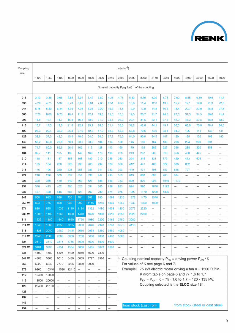
Coupling n [min�1]
size
1120 1250 1400 1500 1600 1800 2000 2240 2500 2800 3000 3150 3550 4000 4500 5000 5600 6000
Nominal capacity PKN [kW]1) of the coupling
018 2,13 2,38 2,66 2,85 3,04 3,42 3,80 4,26 4,75 5,32 5,70 6,00 6,75 7,60 8,55 9,50 10,6 11,4
036 4,26 4,75 5,32 5,70 6,08 6,84 7,60 8,51 9,50 10,6 11,4 12,0 13,5 15,2 17,1 19,0 21,3 22,8
044 5,15 5,80 6,44 6,90 7,36 8,28 9,20 10,3 11,5 12,9 13,8 14,5 16,3 18,4 20,7 23,0 25,8 27,6
066 7,70 8,60 9,70 10,4 11,0 12,4 13,8 15,5 17,3 19,3 20,7 21,7 24,5 27,6 31,3 34,5 38,6 41,4
098 11,8 13,1 14,7 15,8 16,8 18,9 21,0 23,5 26,3 29,4 31,5 33,1 37,3 42,0 47,3 52,5 58,8 63,0
113 15,7 17,5 19,6 21,0 22,4 25,2 28,0 31,4 35,0 39,2 42,0 44,1 49,7 56,0 63,0 70,0 78,4 84,0
123 26,3 29,4 32,9 35,3 37,6 42,3 47,0 52,6 58,8 65,8 70,5 74,0 83,4 94,0 106 118 132 141
129 33,6 37,5 42,0 45,0 48,0 54,0 60,0 67,2 75,0 84,0 90,0 94,5 107 120 135 150 168 180
149 58,2 65,0 72,8 78,0 83,2 93,6 104 116 130 146 156 164 185 208 234 260 291 —
161 71,7 80,0 89,6 96,0 102 115 128 143 160 179 192 202 227 256 288 320 358 —
184 99,7 111 125 135 142 160 178 199 223 249 267 280 316 356 400 445 — —
210 118 131 147 158 168 189 210 235 263 294 315 331 373 420 473 525 — —
214 165 184 206 220 235 265 294 329 368 412 441 463 522 588 662 — — —
215 176 196 220 236 251 283 341 352 393 440 471 495 557 628 707 — — —
222 248 276 309 332 354 398 442 495 553 619 663 696 785 884 — — — —
228 328 366 410 440 469 527 586 656 733 820 879 923 1040 1172 — — — —
231 370 413 462 495 528 594 660 739 825 924 990 1040 1172 — — — — —
237 437 488 546 585 624 702 780 874 975 1092 1170 1230 1385 — — — — —
247 550 613 686 735 784 882 980 1098 1230 1372 1470 1540 — — — — — —
259 W 694 775 868 930 992 1116 1240 1389 1550 1736 1860 1950 — — — — — —
271 830 925 1036 1110 1184 1332 1480 1658 1850 2072 2220 — — — — — — —
285 W 1008 1130 1260 1350 1440 1620 1800 2016 2250 2520 2700 — — — — — — —
311 1232 1380 1540 1650 1760 1980 2200 2465 2750 3080 — — — — — — — —
314 W 1646 1838 2058 2205 2350 2646 2940 3293 3675 4116 — — — — — — — —
316 1826 2040 2280 2445 2610 2934 3260 3650 4080 — — — — — — — — —
319 W 2240 2500 2800 3000 3200 3600 4000 4480 5000 — — — — — — — — —
324 2810 3140 3515 3765 4020 4520 5020 5620 — — — — — — — — — —
329 W 3401 3795 4251 4554 5858 5465 6073 6802 — — — — — — — — — —
335 4100 4580 5125 5490 5860 6590 7320 — — — — — — — — — — —
341 W 4808 5366 6010 6439 6869 7727 8586 —
353 6220 6940 7770 8225 8880 9990 — —
378 9260 10340 11580 12410 — — — —
412 13450 15000 — — — — — —
416 18500 20600 — — — — — —
420 23400 26100 — — — — — —
426 — — — — — — — —
432 — — — — — — — —
443 — — — — — — — —
454 — — — — — — — —
9
1) Coupling nominal capacity PKN = driving power PAN. K
For values of K see page 6 and 7.Example: 75 kW electric motor driving a fan n = 1500 R.P.M.
K (from table on page 6 and 7) 1,6 to 1,7PKN = PAN
. K = 75 . 1,6 to 1,7 = 120 � 135 kW,Coupling selected is the ELCO size 184.
from stock (steel or cast steel)from stock (cast iron)

10
Permissible Misalignment
Example:ELCO Coupling size 214 with TKN /TAN = 2,5and speed n = 200 R.P.M.
1. permissible radial misalignment∆ r = 0,25 mm or
2. permissible angular misalignment∆ corresponding to ∆ b = 0,85 mm or
3. permissible radial and angular misalignment:e.g. if ther is already a ∆ b of 0,5 then∆ r can be 0,25 minus 0,15 = 0,1 mm.
The permissible angularmisalignment ∆is given as a measurablelinear dimension ∆ b.
Gap size at widest point ∆∆ b
Coupling size
Readjustment Forcesfrom Radial Displacement
11
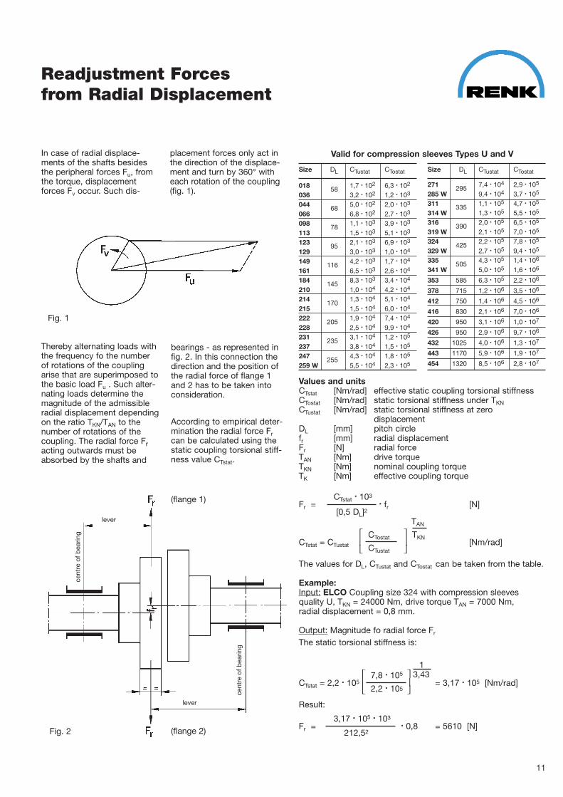
In case of radial displace�ments of the shafts besidesthe peripheral forces Fu, fromthe torque, displacementforces Fv occur. Such dis�
Thereby alternating loads withthe frequency fo the numberof rotations of the couplingarise that are superimposed tothe basic load Fu . Such alter�nating loads determine themagnitude of the admissibleradial displacement dependingon the ratio TKN/TAN to thenumber of rotations of thecoupling. The radial force Fracting outwards must beabsorbed by the shafts and
placement forces only act inthe direction of the displace�ment and turn by 360° witheach rotation of the coupling(fig. 1).
Fig. 1
bearings � as represented infig. 2. In this connection thedirection and the position ofthe radial force of flange 1and 2 has to be taken intoconsideration.
According to empirical deter�mination the radial force Frcan be calculated using thestatic coupling torsional stiff�ness value CTstat.
Fig. 2
Size DL CTustat CTostat
018 58 1,7 . 102 6,3 . 102
036 3,2 . 102 1,2 . 103
044 68 5,0 . 102 2,0 . 103
066 6,8 . 102 2,7 . 103
098 78 1,1 . 103 3,9 . 103
113 1,5 . 103 5,1 . 103
123 95 2,1 . 103 6,9 . 103
129 3,0 . 103 1,0 . 104
149 116 4,2 . 103 1,7 . 104
161 6,5 . 103 2,6 . 104
184 145 8,3 . 103 3,4 . 104
210 1,0 . 104 4,2 . 104
214 170 1,3 . 104 5,1 . 104
215 1,5 . 104 6,0 . 104
222 205 1,9 . 104 7,4 . 104
228 2,5 . 104 9,9 . 104
231 235 3,1 . 104 1,2 . 105
237 3,8 . 104 1,5 . 105
247 255 4,3 . 104 1,8 . 105
259 W 5,5 . 104 2,3 . 105
Valid for compression sleeves Types U and V
Size DL CTustat CTostat
271 295 7,4 . 104 2,9 . 105
285 W 9,4 . 104 3,7 . 105
311 335 1,1 . 105 4,7 . 105
314 W 1,3 . 105 5,5 . 105
316 390 2,0 . 105 6,5 . 105
319 W 2,1 . 105 7,0 . 105
324 425 2,2 . 105 7,8 . 105
329 W 2,7 . 105 9,4 . 105
335 505 4,3 . 105 1,4 . 106
341 W 5,0 . 105 1,6 . 106
353 585 6,3 . 105 2,2 . 106
378 715 1,2 . 106 3,5 . 106
412 750 1,4 . 106 4,5 . 106
416 830 2,1 . 106 7,0 . 106
420 950 3,1 . 106 1,0 . 107
426 950 2,9 . 106 9,7 . 106
432 1025 4,0 . 106 1,3 . 107
443 1170 5,9 . 106 1,9 . 107
454 1320 8,5 . 106 2,8 . 107
Values and unitsCTstat [Nm/rad] effective static coupling torsional stiffnessCTostat [Nm/rad] static torsional stiffness under TKNCTustat [Nm/rad] static torsional stiffness at zero
displacementDL [mm] pitch circlefr [mm] radial displacementFr [N] radial forceTAN [Nm] drive torqueTKN [Nm] nominal coupling torqueTK [Nm] effective coupling torque
CTstat. 103
Fr = . fr [N][0,5 DL]2
TAN
CTostat TKNCTstat = CTustat [Nm/rad]
CTustat
The values for DL, CTustat and CTostat can be taken from the table.
Example:Input: ELCO Coupling size 324 with compression sleeves quality U, TKN = 24000 Nm, drive torque TAN = 7000 Nm,radial displacement = 0,8 mm.
Output: Magnitude fo radial force Fr
The static torsional stiffness is:
1 7,8 . 105 3,43
CTstat = 2,2 . 105 = 3,17 . 105 [Nm/rad] 2,2 . 105
Result:
3,17 . 105 . 103
Fr = . 0,8 = 5610 [N]212,52
lever
lever
cent
re o
f b
earin
g
cent
re o
f b
earin
g
(flange 1)
(flange 2)

ELCO Coupling Type N/WSizes 018 � 319 W
The ELCO couplings types Nand W are used for the flexibleconnection of shafts.
Description:The ELCO coupling type Nconsists essentially of the twocoupling halves, flanges 1 and2 and the transmission bolts
(4) on which the rubber com�pression sleeves (5) aremounted The finely groundtransmission bolts (4) aremade of steel and are insertedwith a specially close fit in thebores (3) of the half coupling,flange 2. They engage, withtheir axially pre�loaded com�
pression sleeves, in the boresprovided in the coupling half,flange 1.
The ELCO coupling type Wcomplements the well�knowntype N.
ELCO coupling type W con�
sists of two identical couplingparts, each with transmittingbolts arranged in alternateorder an dthe compressionsleeves.
Instructions for designers speed material interme� coupling available sizes anddiate disc5) bolts their designation
The coupling flanges can be axially separated. From size 149 the cast iron without NGOM. � 247 to 454
shaft can beradially dismantled, after removing the coupling bolts Iwith NGZM. � 247 to 353
without axial displacement. steel or withoutsolid
NSOM. � 018 to 454cast iron with NSZM. � 149 to 353
The coupling can be provided with intermediate disc for the fitting II steel or without solid NSOM. � 018 to 129and removal of endless belts. cast iron with hollow NSOH. � 149 to 454
from stock1) For maximum speed II, from size 149 only
steel couplings with hollow bolts must beused.
2) Standard fitting dimension bnorm = 1/2 bmax
3) Space required for driving out the trans�mission boltsx = for couplings without intermediate discx* = for couplings with intermediate disc
4) y = space required for removing the com�
pression sleeves5) The material of the intermediate disc steel.6) Withdrawal holes up to size 237 on
request � from size 247 holes are providedas standard.
12
Coupling Max. Cast iron and Steel / Cast steeltorque speeds 1)
Flanges 1 and 2Couplingsize TKN I II a1 l1 l2 bmax
2) z h1 h2 o p Dl6) d 6) t 6) x 3) x* 3) y 4)
[Nm] [min�1] [min�1] [mm] [mm] [mm] [mm] [mm] [mm] [mm] [mm] [mm] [mm] [mm] [mm]
018 18 . 1006000 — 87 30 6 — 21 30 — 40 M 6 12 28 — 28
036 36 . 100
044 44 . 1006000 — 97 35 6 — 21 30 — 50 M 8 15 25 — 25
066 66 . 100
098 98 . 1006000 — 112 40 6 — 26 36 — 60 M 8 15 30 — 30
113 13 . 101
123 23 . 1016000 — 130 50 6 — 26 36 — 70 M 8 15 20 — 20
129 29 . 101
149 49 . 1013600 5600 160 60 4 16 30 46 42 80 M 10 20 25 40 25
161 61 . 101
184 84 . 1013000 5000 190 75 4 16 30 46 42 100 M 10 20 10 25 10
210 10 . 102
214 14 . 1022650 4500 255 90 5 20 37 54 49 115 M 12 25 10 25 15
215 15 . 102
222 22 . 1022250 4000 270 100 6 20 45 63 61 125 M 12 25 20 35 20
228 28 . 102
231 31 . 1022000 3600 300 120 6 20 45 63 61 145 M 12 25 5 15 0
237 37 . 102
247 47 . 1021800 3300 340 140 6 25 55 74 73 170 M 16 30 5 20 0
259 W 59 . 102
271 71 . 1021650 3000 380 160 6 25 55 74 73 185 M 20 35 0 0 0
285 W 85 . 102
311 11 . 1031500 2800 440 180 7 25 68 90 92 205 M 20 35 0 10 0
314 W 14 . 103
316 16 . 1031250 2500 500 200 7 25 68 90 92 225 M 20 35 0 0 0
319 W 19 . 103

Cast iron Steel / Cast ironFlange 1 N / Flange 1 W / Flange 2 W Flange 2 N Flange 1 N / Flange 1 W / Flange 2 W Flange 2 N
Coupling hub rough finished bore hub rough finished bore hub rough finished bore hub rough finished boresize N1 bore 2) size 1) N2 bore 2) size 1) N1 bore 2) size 1) N2 bore 2) size 1)
size D1 size D2 size D1 size D2[mm] [mm] [mm] [mm] [mm] [mm] [mm] [mm] [mm] [mm] [mm] [mm]
018 35 9 10 � 20 40 9 10 � 25036
044 45 11 12 � 28 50 11 12 � 30066
098 52 15 16 � 32 63 15 16 � 40113
123 68 18 19 � 45 80 18 19 � 52129
149 82 18 19 � 55 82 18 19 � 55161
184 110 23 24 � 75 110 23 24 � 75210
214 125 29 30 � 85 135 29 30 � 90215
222 150 34 35 � 100 150 34 35 � 100228
231 180 39 40 � 120 180 39 40 � 120237
247 130 44 45 � 75 145 49 50 � 85 180 44 45 � 120 200 44 45 � 135259 W 180 73 > 75 � 110 200 83 > 85 � 120
271 150 53 55 � 90 150 53 55 � 90180 88 > 90 � 110 180 88 > 90 � 110 220 53 55 � 145 220 53 55 � 145
285 W 205 108 > 110 � 125 220 108 > 110 � 135
311 165 63 65 � 100 165 63 65 � 100205 98 > 100 � 125 205 98 > 100 � 125 250 63 65 � 165 250 63 65 � 165
314 W 230 123 > 125 � 140 250 123 > 125 � 150
316 180 73 75 � 110 180 73 75 � 110 170 73 75 � 110 170 73 75 � 110230 108 > 110 � 140 230 108 > 110 � 140 215 108 > 110 � 140 215 108 > 110 � 140
319 W 260 138 > 140 � 155 280 138 > 140 � 170 260 138 > 140 � 170 280 138 > 140 � 185
Type N Type W
Design with intermediate disc Design with intermediate disc
Bore of hub chamfered: Size 018 � 129 = 1 x 45°, Size 149 � 259 W = 1,5 x 45°, Size 271 � 319 W = 2 x 45°
from stock 1) The couplings are normally bored to DIN7161 using ISO tolerances “K 7” or “H 7”.Recommended fit is:h 6 / K 7 or m 6 / H 7 or k 6 / H 7.
Sizes 018 � 210 will always be suppliedwith set crew when ready bored and key�wayed.
2) Rough bores have no fit tolerance.Parallel keys and taper keys are supplied
on request, at extra charge.With high shock�loads or reduced hubsresp. the load on the key must bechecked.
For ordering instructions refer to page 15.
13
Flange 2 W
Design for sizes 018 � 129 Design for sizes 149 � 316
Flange 2 NFlange 1 N
Flange 2 NFlange 1 N
Flange 1 W

Coupling Max. Cast iron and Steel / Cast steeltorque speeds 1)
flanges 1 and 2Couplingsize TKN I II a1 l1 l2 bmax
2) z h1 h2 f o p Dl d t x, x* 3) y 4)
[Nm] [min�1] [min�1] [mm] [mm] [mm] [mm] [mm] [mm] [mm] [mm] [mm] [mm] [mm] [mm] [mm] [mm]
324 24 . 103 76 165
329 W 29 . 103 1120 2250 560 220 8 30 83—
46 106 107 200 M 20 35 0 0240
335 35 . 103 76 180
341 W 41 . 103 1000 2000 640 250 8 30 83—
46 106 107 220 M 20 35 0 0260200
353 53 . 103 850 1750 750 280 9 30 102 93 58 127 128 250 M 24 42 0 0300210
378 78 . 103 750 1500 880 320 9 — 102 93 58 127 128 250 M 24 42 0 0290330240
412 12 . 104 630 1300 960 350 10 — 128 115 60 158 159 280 M 24 52 0 0320380240
416 16 . 104 630 1300 1040 375 10 — 128 115 60 158 159 280 M 24 52 0 0320380260
420 20 . 104 560 1200 1160 400 10 — 128 115 60 158 159 310 M 24 52 0 0360420310360
426 26 . 104 500 1050 1210 425 12 — 160 148 75 195 200 410 M 24 62 0 0440480320400
432 32 . 104 500 1050 1285 450 12 — 160 148 75 195 200 470 M 24 62 0 0510570330410
443 43 . 104 450 890 1430 500 12 — 160 148 75 195 200 490 M 24 70 0 0530590370440
454 54 . 104 400 750 1580 560 12 — 160 148 75 195 200 510 M 24 70 0 0580650
ELCO Coupling Type N/WSizes 324 � 454 W
The ELCO couplings types Nand W are used for the flexibleconnection of shafts.
Description:The ELCO coupling type Nconsists essentially of the twocoupling halves, flanges 1 and2, and the transmission bolts
(4) on which the rubber com�pression sleeves (5) aremounted. The finely groundtransmission bolts (4) aremade of steel and are insertedwith a specially close fit in thebores (3) of the half coupling,flange 2. They engage, withtheir axially pre�loaded com�
pression sleeves, in the boresprovided in the coupling half,flange 1.
The ELCO coupling type Wcomplements the well�knowntype N.
ELCO coupling type W con�sists of two identical couplingparts. each with transmittingbolts arranged in alternateorder and the compressionsleeves.
Instructions for designers speed material interme� coupling available sizes anddiate disc5) bolts their designation
The coupling flanges can be axially separated. From size 149 the cast iron without NGOM. � 247 to 454
shaft can be radially dismantled, after removing the coupling bolts Iwith NGZM. � 247 to 353
without axial displacement. steel or withoutsolid
NSOM. � 018 to 454cast steel with NSZM. � 149 to 353
The coupling can be provided with intermediate disc for the fitting II steel or without solid NSOM. � 018 to 129and removal of endless belts. cast steel with hollow NSOH. � 149 to 454
from stock (iron only) Couplings for torque higher than TKN = 54 . 104 Nm are available on request. For foot notes see pages 12 and 13.
14
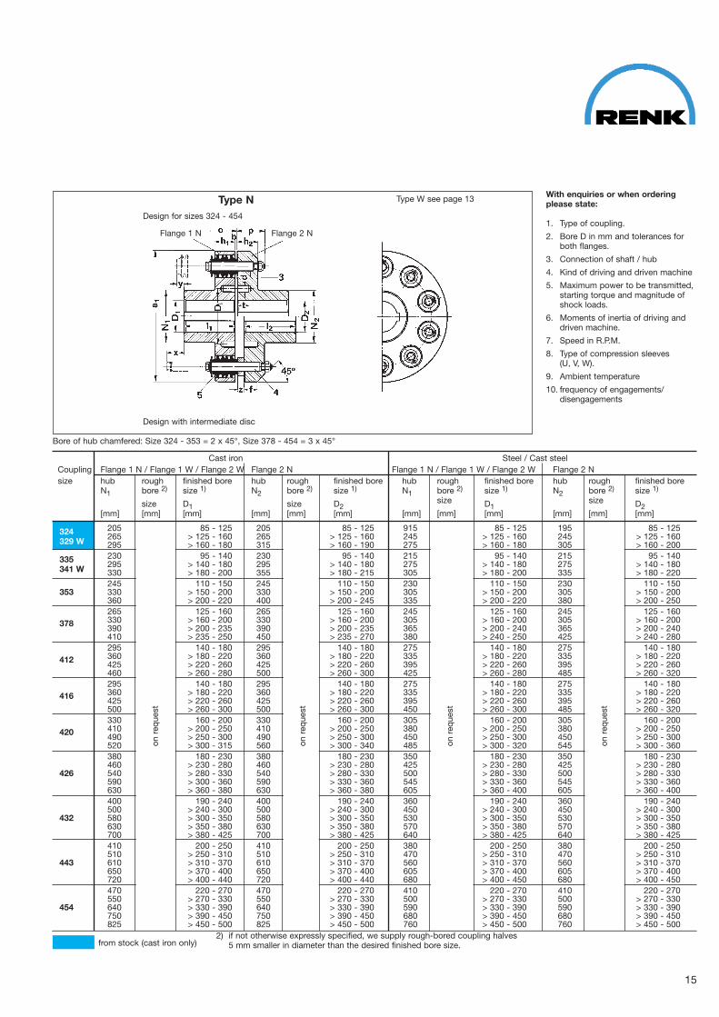
Type N Type W see page 13
Design for sizes 324 � 454
Design with intermediate disc
Bore of hub chamfered: Size 324 � 353 = 2 x 45°, Size 378 � 454 = 3 x 45°
Cast iron Steel / Cast steelCoupling Flange 1 N / Flange 1 W / Flange 2 W Flange 2 N Flange 1 N / Flange 1 W / Flange 2 W Flange 2 Nsize hub rough finished bore hub rough finished bore hub rough finished bore hub rough finished bore
N1 bore 2) size 1) N2 bore 2) size 1) N1 bore 2) size 1) N2 bore 2) size 1)
size D1 size D2size D1
size D2[mm] [mm] [mm] [mm] [mm] [mm] [mm] [mm] [mm] [mm] [mm] [mm]
205 85 � 125 205 85 � 125 915 85 � 125 195 85 � 125324 265 > 125 � 160 265 > 125 � 160 245 > 125 � 160 245 > 125 � 160329 W 295 > 160 � 180 315 > 160 � 190 275 > 160 � 180 305 > 160 � 200230 95 � 140 230 95 � 140 215 95 � 140 215 95 � 140335 295 > 140 � 180 295 > 140 � 180 275 > 140 � 180 275 > 140 � 180341 W 330 > 180 � 200 355 > 180 � 215 305 > 180 � 200 335 > 180 � 220245 110 � 150 245 110 � 150 230 110 � 150 230 110 � 150
353 330 > 150 � 200 330 > 150 � 200 305 > 150 � 200 305 > 150 � 200360 > 200 � 220 400 > 200 � 245 335 > 200 � 220 380 > 200 � 250265 125 � 160 265 125 � 160 245 125 � 160 245 125 � 160
378 330 > 160 � 200 330 > 160 � 200 305 > 160 � 200 305 > 160 � 200390 > 200 � 235 390 > 200 � 235 365 > 200 � 240 365 > 200 � 240410 > 235 � 250 450 > 235 � 270 380 > 240 � 250 425 > 240 � 280295 140 � 180 295 140 � 180 275 140 � 180 275 140 � 180
412 360 > 180 � 220 360 > 180 � 220 335 > 180 � 220 335 > 180 � 220425 > 220 � 260 425 > 220 � 260 395 > 220 � 260 395 > 220 � 260460 > 260 � 280 500 > 260 � 300 425 > 260 � 280 485 > 260 � 320295 140 � 180 295 140 � 180 275 140 � 180 275 140 � 180
416 360 > 180 � 220 360 > 180 � 220 335 > 180 � 220 335 > 180 � 220425 > 220 � 260 425 > 220 � 260 395 > 220 � 260 395 > 220 � 260500 > 260 � 300 500 > 260 � 300 450 > 260 � 300 485 > 260 � 320330 160 � 200 330 160 � 200 305 160 � 200 305 160 � 200
420 410 > 200 � 250 410 > 200 � 250 380 > 200 � 250 380 > 200 � 250490 > 250 � 300 490 > 250 � 300 450 > 250 � 300 450 > 250 � 300520 > 300 � 315 560 > 300 � 340 485 > 300 � 320 545 > 300 � 360380 180 � 230 380 180 � 230 350 180 � 230 350 180 � 230460 > 230 � 280 460 > 230 � 280 425 > 230 � 280 425 > 230 � 280
426 540 > 280 � 330 540 > 280 � 330 500 > 280 � 330 500 > 280 � 330590 > 300 � 360 590 > 330 � 360 545 > 330 � 360 545 > 330 � 360630 > 360 � 380 630 > 360 � 380 605 > 360 � 400 605 > 360 � 400400 190 � 240 400 190 � 240 360 190 � 240 360 190 � 240500 > 240 � 300 500 > 240 � 300 450 > 240 � 300 450 > 240 � 300
432 580 > 300 � 350 580 > 300 � 350 530 > 300 � 350 530 > 300 � 350630 > 350 � 380 630 > 350 � 380 570 > 350 � 380 570 > 350 � 380700 > 380 � 425 700 > 380 � 425 640 > 380 � 425 640 > 380 � 425410 200 � 250 410 200 � 250 380 200 � 250 380 200 � 250510 > 250 � 310 510 > 250 � 310 470 > 250 � 310 470 > 250 � 310
443 610 > 310 � 370 610 > 310 � 370 560 > 310 � 370 560 > 310 � 370650 > 370 � 400 650 > 370 � 400 605 > 370 � 400 605 > 370 � 400720 > 400 � 440 720 > 400 � 440 680 > 400 � 450 680 > 400 � 450470 220 � 270 470 220 � 270 410 220 � 270 410 220 � 270550 > 270 � 330 550 > 270 � 330 500 > 270 � 330 500 > 270 � 330
454 640 > 330 � 390 640 > 330 � 390 590 > 330 � 390 590 > 330 � 390750 > 390 � 450 750 > 390 � 450 680 > 390 � 450 680 > 390 � 450825 > 450 � 500 825 > 450 � 500 760 > 450 � 500 760 > 450 � 500
With enquiries or when orderingplease state:
1. Type of coupling.
2. Bore D in mm and tolerances forboth flanges.
3. Connection of shaft / hub
4. Kind of driving and driven machine
5. Maximum power to be transmitted,starting torque and magnitude ofshock loads.
6. Moments of inertia of driving anddriven machine.
7. Speed in R.P.M.
8. Type of compression sleeves (U, V, W).
9. Ambient temperature
10. frequency of engagements/disengagements
from stock (cast iron only)2) if not otherwise expressly specified, we supply rough�bored coupling halves
5 mm smaller in diameter than the desired finished bore size.
15
on r
eque
st
on r
eque
st
on r
eque
st
on r
eque
st
Flange 2 NFlange 1 N
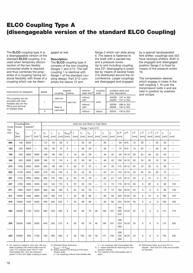
ELCO Coupling Type A(disengageable version of the standard ELCO Coupling)
The ELCO coupling type A isa disengageable version of thestandard ELCO coupling. It isused when temporary discon�nection of the two flexiblyconnected shafts is requiredand thus combines the prop�erties of a coupling having tor�sional flexibility with those of acoupling which can be disen�
gaged at rest.
Description:The ELCO coupling type Aconsists of the two couplingflanges 1 and 2/12. The halfcoupling 1 is identical withflange 1 of the standard cou�pling design. Part 2/12 com�prises the sleeve 12 and
flange 2 which can slide alongit. The sleeve is fastened tothe shaft with a parallel keyand a pressure screw.Up to and including couplingsize 231 disengaging is possi�ble by means of several holes(14) distributed around the cir�cumference. Larger couplingsare disengaged and engaged
by a special handoperatedfork shifter; couplings size 353have racktype shifters. Both inthe engaged and disengagedposition flange 2 is fixed bymeans of the pressure screw16.
The compression sleeveswhich engage in holes in thehalf coupling 1, fit over thetransmission bolts 4 and areheld in position by washersand circlips.
Instructions for designers speed material interme� coupling available sizes andcoupling sleeve diate disc5) bolts their description
The coupling can be cast iron without AGOM. � 247 to 353
provided with inter� Iwith AGZM. � 247 to 353
mediate disc for the cast ironwithout
solidASOM. � 098 to 353
fitting and removal steel or with ASZM. � 149 to 353of endless belts
II cast steel without hollow ASOH. � 149 to 353
Coupling Max. Cast iron and Steel or Cast SteelCoup� torque speeds1)
Flange 1 and 2/12lingsize TKN I II a1 l1 l2 bmax
2) z h1 h2 f o p Dl6) d 6) t 6) x 3) x* 3) y 4) s e
[Nm] [min�1] [min�1] [mm] [mm] [mm] [mm] [mm] [mm] [mm] [mm] [mm] [mm] [mm] [mm] [mm] [mm] [mm] [mm] [mm]
098 100 6000 — 112 40 60 6 — 26 26 — 36 — 60 M 8 15 30 — 30 40 —
123 225 6000 — 130 50 75 6 — 26 26 — 36 — 70 M 8 15 20 — 20 40 —
149 500 3600 5600 160 60 100 4 16 30 30 — 46 42 80 M 10 20 25 40 25 50 —
184 850 3000 5000 190 75 110 4 16 30 30 — 46 42 100 M 10 20 10 25 10 50 —
214 1400 2650 4500 225 90 130 5 20 37 37 — 54 49 115 M 12 25 10 25 15 60 —
222 2100 2250 4000 270 100 150 6 20 45 45 — 63 61 125 M 12 25 20 35 20 70 —
231 3150 2000 3600 300 120 160 6 20 45 45 — 63 61 145 M 12 25 5 15 0 70 —
247 4700 1800 3300 340 140 175 6 25 55 55 — 74 73 170 M 16 30 5 20 0 80 120
271 7000 1650 3000 380 160 190 6 25 55 55 — 74 73 185 M 20 35 0 0 0 80 130
311 10500 1500 2800 440 180 210 7 25 68 68 — 90 92 205 M 20 35 0 10 0 100 145
316 15500 1250 2500 500 200 225 7 25 68 68 — 90 92 225 M 20 35 0 0 0 100 160
165324 24000 1120 2250 560 220 250 8 30 83 76 46 106 107 200 M 20 35 0 0 0 115 170
240
180335 35000 1000 2000 640 250 275 8 30 83 76 46 106 107 220 M 20 35 0 0 0 115 200
260
200353 53000 850 1700 750 280 300 9 30 102 93 58 127 128 250 M 24 42 0 0 0 140 230
300
16
1) For maximum speed II, from size 149 onlysteel couplings with hollow bolts must beused. For coupling sizes 149�271 withintermediate disc, only the maximumspeed I of the next larger coupling is used.
2) Standard fitting dimensionbnorm = 1/2 bmax
3) Space required for driving out the trans�mission boltsx = for couplings without intermediate disc
x* = for couplings with intermediate disc4) y = space required for removing the com�
pression sleeves.5) The material of the intermediate disc is
steel.
6) Withdrawal holes up to size 231 onrequest � from size 247 holes are providedas standard.

17
Designs with engaging holes for sizes 098 � 231 Design for sizes 247 � 353
Sizes 149 � 231 with removable coupling bolts Design with intermediate disc
Bore of hub chamfered: Size 098 � 123 = 1 x 45°, Size 149 � 247 = 1,5 x 45°, Size 271 � 353 = 2 x 45°
Cast iron Steel 3)
Coupling Flange 1 Flange 2/12 Flange 1 Flange 2/12size hub rough finished hub sleeve finished hub rough finished hub sleeve finished
N1 bore 2) bore size 1) N2 N12 bore size 1) N1 bore 2) bore size 1) N2 N12 bore size 1)
size D1 D2 size D1 D2[mm] [mm] [mm] [mm] [mm] [mm] [mm] [mm] [mm] [mm] [mm] [mm]
098 52 15 16 � 32 63 48 16 � 30
123 68 18 19 � 45 80 60 19 � 40
149 82 18 19 � 55 90 70 19 � 45
184 110 23 24 � 75 120 90 24 � 60
214 125 29 30 � 85 140 105 30 � 70
222 150 34 35 � 100 160 120 35 � 80
231 180 39 40 � 120 180 135 40 � 90
247 130 44 45 � 75 125 45 � 80 180 44 45 � 120 200 125 45 � 80180 73 > 75 � 100 200 150 > 80 � 100 150 > 80 � 110
150 53 55 � 90 180 135 55 � 80 135 55 � 80271 180 88 > 90 � 110 220 53 55 � 145 220
205 108 > 110 � 125 220 170 > 80 � 110 170 > 80 � 110
165 63 65 � 100 205 155 65 � 100 155 65 � 100311 205 98 > 100 � 125 250 63 65 � 165 250
230 123 > 125 � 140 250 190 > 100 � 130 190 100 � 130
180 73 75 � 110 230 170 75 � 110 170 73 75 � 110 170 75 � 110316 230 108 > 110 � 140 215 108 > 110 � 140 280
260 138 > 140 � 155 300 235 > 110 � 160 260 138 > 140 � 170 220 > 110 � 150
205 85 � 125 265 200 85 � 130 195 85 � 125 245 190 85 � 120324 265 125 � 160 > 130 � 180 245 > 125 � 160
295 > 160 � 180 350 270 > 130 � 180 275 > 160 � 180 340 270 > 120 � 170
230 95 � 140 295 220 95 � 145 215 95 � 140 275 210 95 � 130335 295 > 140� 180 275 > 140 � 180
330 > 180 � 200 400 300 > 145 � 200 305 > 180 � 200 380 300 > 130 � 190
245 110 � 150 330 250 110 � 160 230 110 � 150 330 250 110 � 160353 330 > 150 � 200 305 > 150 � 200
360 > 200 � 220 450 315 > 160 � 220 335 > 200 � 220 400 315 > 160 � 220
1) The couplings are normally bored to DIN7161 using ISO tolerances „K 7“ or „H 7“.Recommended fit is h 6 / K 7 or m 6 / H 7resp. k 6 / H 7.
2) Rough bores have no fit tolerance.
3) Larger couplings are made of cast steel.
4) If not otherwise expressly specified, wesupply rough�bored coupling halves to 5 mm smaller in diameter than the desiredfinished bore size.
Parallel keys and taper keys are suppliedon request, at extra charge. With high shock�loads or reduced hubsresp., the load on the key must bechecked.
With enquiries or when orderingplease state:
1. Type of coupling.
2. Bore D in mm and tolerances forboth flanges.
3. Connection of shaft / hub
4. Kind of driving and driven machine
5. Maximum power to be transmitted,starting torque and magnitude ofshock loads.
6. Moments of inertia of driving anddriven machine.
7. Speed in R.P.M.
8. Type of compression sleeves (U, V, W).
9. Ambient temperature
10. frequency of engagements/disengagements
on r
eque
st 4
)
on r
eque
st 4
)
Flange 2/12Flange 1 Flange 2/12Flange 1
Sizes 098 and 123fixed coupling bolts

18
ELCO Coupling Type B(shear pin coupling)
The ELCO coupling type B isa modified design of the stan�dard ELCO coupling in so faras it is a safety coupling ableto protect the flexibly connect�ed machine against undulyhigh loads. In the event ofoverloading taking place thetwo shafts are separated fromeach other by shearing of thepins.
This coupling thus combinesthe properties of a torsionallyflexible coupling with those ofa coupling protected againstoverload.
Description:
The ELCO coupling type Bconsists of the couplinghalves 1 and 2/12. The flange1 is the same as flange 1 ofthe standard ELCO couplingflange 2/12 is made up of aflange hub 12, fixed to theshaft by means of a parallelkey and flange 2 which ismounted on the flange huband are able to turn freely. Thetwo parts are connected bythe cast iron shear pins 14.The torque is transmittedthrough shear pins 14, trans�mission bolts 4 and compres�
sion sleeves 5 which engagewith holes in the couplingflange 1. Shear pins and com�pression sleeves are thusinserted in series. Flange 2which can turn freely is heldaxially by a disc 16. The run�ning surfaces are lubricated bya grease nipple 17. For certainfields of application wherethere is a higher circumferen�tial speed flange 2, which canturn freely, is supported onpart 12 by a PTFE lining togive it a more favourable run�down action. The maximumamount of torque that can betransmitted is determined by
different depths of groove inthe shear pins. The breakingtorque TKB has a speed of ±25% because of the differ�ences in the strength fo theshear pin material.Consequently the breakingtorque TKB must have an ade�quate safety margin above thedriving torque (TKB ≈ 2 TAN).
Whenever the shear pinsbreak as a result of overloadthe driving machine should bestopped immediately as thecoupling is not suitable forrunning for long periods with�out load.
Min.per� Cast iron and Steel or Cast steelCoup� missible Max. Flanges 1 and 2/12
Coup� ling breaking speedsling torque1) torque2) 3)
size TKN TKB a1 l1 l29) bmax4) z h1 h2 f o p Dl
8) d 8) t 8) x 5) x* 5) y 6) m e
[Nm] [Nm] [min�1] [mm] [mm] [mm] [mm] [mm] [mm] [mm] [mm] [mm] [mm] [mm] [mm] [mm] [mm] [mm] [mm] [mm]
149 49 . 101 160 800 160 60 80 4 16 30 30 — 46 42 80 M 10 20 25 40 25 38 140
184 84 . 101 280 710 190 75 95 4 16 30 30 — 46 42 100 M 10 20 10 25 10 42 175
214 14 . 102 340 630 225 90 110 5 20 37 37 — 54 49 115 M 12 25 10 25 15 42 210
222 22 . 102 650 560 270 100 130 6 20 45 45 — 63 61 125 M 12 25 20 35 20 55 245
231 31 . 102 740 500 300 120 145 6 20 45 45 — 63 61 145 M 12 25 5 15 0 55 270
247 47 . 102 1150 450 340 140 160 6 25 55 55 — 74 73 170 M 16 30 5 20 0 68 310
271 71 . 102 1250 400 380 160 180 6 25 55 55 — 74 73 185 M 20 35 0 0 0 68 340
311 11 . 103 2500 355 440 180 200 7 25 68 68 — 90 92 205 M 20 35 0 10 0 85 390
316 16 . 103 2800 280 500 200 220 7 25 68 68 — 90 92 225 M 20 35 0 0 0 85 450
165324 24 . 103 6000 250 560 220 240 8 30 83 76 46 106 107 200 M 20 35 0 0 0 110 510
240
180335 35 . 103 7000 225 640 250 260 8 30 83 76 46 106 107 220 M 20 35 0 0 0 110 570
260
200353 53 . 103 10000 200 750 280 290 9 30 102 93 58 127 128 250 M 24 42 0 0 0 130 660
300
1) Also the maximum permissible breakingtorque TKB.
2) For technical reasons associated withmanufacture the minimum breaking torquemust not fall below these values.
3) Higher speeds on request.4) Standard fitting dimension
bnorm = 1/2 bmax5) Space required for driving out the trans�
mission bolts
x = for couplings without intermediate discx* = for couplings with intermediate disc.
6) y = space required vor removing the com�pression sleeves.
7) The material of the intermediate disc is
steel.8) Withdrawal holes up to size 231 on
request � from size 247 holes are providedas standard.
9) Also the length of the seating.
Instructions for designers material interme� coupling available sizes andcoupling flange hub diate disc 5) bolts their designation
After removal of the coupling bolts the shaft can be radially dismantled, cast iron without BGOM. � 247 to 454without axial displacement. The coupling can be provided with intermediate cast iron with BGZM. � 247 to 353disc for the fitting and removal of endless belts. steel or without
solidBSOM. � 018 to 454
cast steel with BSZM. � 149 to 353

19
Design with intermediate disc
Bore of hub chamfered: Size 149 � 247 = 1,5 x 45°, Size 271 � 353 = 2 x 45°
Cast iron Steel 3)
Coupling Flange 1 Flange 2/12 Flange 1 Flange 2/12size hub rough finished hub part finished hub rough finished hub part finished
N1 bore 2) bore size 1) N12 bore size 1) N1 bore 2) bore size 1) N12 bore size 1)
size D1 D2 size D1 D2[mm] [mm] [mm] [mm] [mm] [mm] [mm] [mm] [mm] [mm]
149 82 18 19 � 55 70 19 � 40
184 110 23 24 � 75 95 24 � 60
214 125 29 30 � 85 110 30 � 70
222 150 34 35 � 100 125 35 � 80
231 180 39 40 � 120 140 40 � 90
247 130 44 45 � 75 160 45 � 100 180 44 45 � 120 160 45 � 100180 73 > 75 � 110
150 53 55 � 90 140 55 � 85 140 55 � 85271 180 88 > 90 � 110 220 53 55 � 145
205 108 > 110 � 125 175 > 85 � 110 175 > 85 � 110
165 63 65 � 100 160 65 � 100 160 65 � 100311 205 98 > 100 � 125 250 63 65 � 165
230 123 > 125 � 140 200 > 100 � 130 200 > 100 � 130
180 73 75 � 110 175 75 � 110 170 73 75 � 110 175 75 � 110316 230 108 > 110 � 140 215 108 > 110 � 140
260 138 > 140 � 155 235 > 110 � 150 260 138 > 140 � 170 235 > 110 � 150
205 85 � 125 235 85 � 140 195 85 � 125 235 85 � 140324 265 > 125 � 160 245 > 125 � 160
295 > 160 � 180 280 > 140 � 170 275 > 160 � 180 280 > 140 � 170
230 95 � 140 260 95 � 150 215 95 � 140 260 95 � 150335 295 > 140� 180 275 > 140 � 180
330 > 180 � 200 320 > 150 � 200 305 > 180 � 200 320 > 150 � 200
245 110 � 150 290 110 � 170 230 110 � 150 290 110 � 170353 330 > 150 � 200 305 > 150 � 200
360 > 200 � 220 360 > 170 � 220 335 > 200 � 220 360 > 170 � 220
1) The couplings are normally bored to DIN7161 using ISO tolerances „K 7“ or „H 7“.Recommended fit is h 6 / K 7 or m 6 / H 7.
2) Rough bores have no fit tolerances. 3) Bigger couplings may be made from cast
steel. In case of steel couplings withoutPTFE coating, flange 12 will be made fromcast iron.
4) If not otherwise expressly specified, wesupply rough�bored coupling halves to 5mm smaller in diameter than the desiredfinished bore size.
Parallel keys and taper keys are suppliedon request, at extra charge.With high shock�loads or reduced hubsresp., the load on the key must bechecked.
With enquiries or when orderingplease state:
1. Type of coupling.
2. Bore D in mm and tolerances forboth flanges.
3. Connection of shaft / hub
4. Kind of driving and driven machine
5. Maximum power to be transmitted,starting torque and magnitude ofshock loads.
6. Magnitude of the breaking torqueTKB.
7. Moments of inertia of driving anddriven machine.
8. Speed in R.P.M.
9. Type of compression sleeves (U, V, W).
10. Ambient temperature
11. frequency of engagements/disengagements
on r
eque
st 4
)
on r
eque
st 4
)
Flange 2/12
Flange 1

ELCO Coupling Type S(with screwed�on brake drum to DIN 15431)
the ELCO couplings type Sare standard ELCO couplingscombined with standard brakedrums to DIN 15431.
Description:The ELCO coupling type Sconsists of coupling halves 1and 2. The half�coupling 1 isidentical with flange 1 of thestandard design. Flange 2 is
provided with a centeringrecess for mounting the brakedrum. For coupling sizes 149(5) and above both the pres�sure screws 13 and the fitteddowels are used for fixing the
brake drum in position. Thecoupling bolts carry the com�pression sleeves 5 whichengage with the holes provid�ed in the coupling flange 1.
Instructions for designers speed material intermed� coupling available sizes anddiate disc 5) bolts their designation
without SGOM. � 247 to 324
cast iron with brake drum GG or GS
The coupling flanges can be axially separated. with SGZM. � 247 to 324From size 149 the shaft can be radially dismantled, I
with brake drum GG or GSafter removing the coupling bolts, without axial dis� without
soildSSOM. � 123 to 324
placement. steel with brake drum GG or GS
with SSZM. � 149 to 324The coupling can be provided with intermediate with brake drum GG or GSdisc for the fitting and removal of endless belts.
II steel without hollow SSOH. � 149 to 454with brake drum GG or GS
Coup� Max. Cast iron and Steel
ling speeds 1) Flange 1 and 2
Coupling torquesize TKN I II a1 l1 l2 bmax
2) z h1 o Dl6) d 6) t 6) x 3) x* 3) y 4)
[Nm] [min�1] [min�1] [mm] [mm] [mm] [mm] [mm] [mm] [mm] [mm] [mm] [mm] [mm] [mm]
123 23 . 101 6000 — 130 50 6 — 26 36 70 M 8 15 20 20 20
149 49 . 101 3600 5600 160 60 4 16 30 46 80 M 10 20 25 40 25
184 84 . 101 3000 5000 190 75 4 16 30 46 100 M 10 20 10 25 10
214 14 . 102 2650 4500 225 90 5 20 37 54 115 M 12 25 10 25 15
222 22 . 102 2250 4000 270 100 6 20 45 63 125 M 12 25 20 35 20
231 31 . 102 2000 3150 300 120 6 20 45 63 145 M 12 25 5 15 0
247 47 . 102 1800 2500 340 140 6 25 55 74 170 M 16 30 5 20 0
271 71 . 102 1650 2000 380 160 6 25 55 74 185 M 20 35 0 0 0
311 11 . 103 1500 1600 440 180 7 25 68 90 205 M 20 35 0 10 0
316 16 . 103 1250 1400 500 200 7 25 68 90 225 M 20 35 0 0 0
165324 24 . 103 1120 2250 560 220 8 30 83 106 200 M 20 35 0 0 0
240
20
1) For maximum speeds II, from size 149 onlysteel couplings with hollow bolts must beused.
Brake drums see page 21.
If the permissible speed for the brakedrum is smaller than that for the coupling,the brake drum speed is the one to beconsidered.
2) When assembling, standard dimension
b = 1/2 bmax
3) space required for driving out the trans�mission boltsx = for couplings without intermediate discx* = for coupllings with intermediate disc.
4) y = space required for removing the com�pression sleeves.
5) The material of the intermediate disc issteel.
6) Withdrawal holes up to size 231 onrequest � from size 247 holes are providedas standard.
For diameters of bores and hubs see type Nsizes 123 to 324.
sizes 123 to 231 not available in cast iron

21
Equally, brake pulleys similar to DIN 15 432 can be supplied
Bore of hub chamfered: Size 123 = 1 x 45°, Size 149 � 247 = 1,5 x 45°, Size 271 � 324 = 2 x 45°
Brake drum to DIN 15431 (part 12)
Coup� combination I combination II combination III
ling A B permissible speed A B permissible speed A B permissible speedsize C.I. C.S. C.I. C.S. C.I. C.S.
[mm] [mm] [min�1] [min�1] [mm] [mm] [min�1] [min�1] [mm] [mm] [min�1] [min�1]
123 — — — — — — — — 200 75 3150 6000
149 — — — — 200 75 3150 5600 250 95 2500 5000
184 — — — — 250 95 2500 5000 315 118 2000 4000
214 250 95 2500 4500 315 118 2000 4000 400 150 1600 3150
222 315 118 2000 4000 400 150 1600 3150 500 190 1250 2500
231 400 150 1600 3150 500 190 1250 2500 630 236 1000 2000
247 500 190 1250 2500 630 236 1000 2000 710 265 800 1600
271 630 236 1000 2000 710 265 800 1600 800 300 710 1400
311 710 265 800 1600 800 300 710 1400 — — — —
316 800 300 710 1400 — — — — — — — —
324 800 300 710 1400 — — — — — — — —
Important instructions fordesign and planning:
The coupling part with thebrake drum should always be
mounted on that shaft endwhich is transmitting the high�
er braking torque. Parallel andtapered keys are supplied onrequest at an extra charge.
With enquiries or when orderingplease state:
1. Type of coupling.
2. Bore D in mm and tolerances forboth flanges.
3. Connection of shaft / hub
4. Kind of driving and driven machine
5. Maximum power to be transmitted,starting torque and magnitude ofshock loads.
6. Moments of inertia of driving anddriven machine.
7. Speed in R.P.M.
8. Type of compression sleeves (U, V, W).
9. Brake drum dimensions.
10. Ambient temperature
11. frequency of engagements/disengagements
Design with intermediate disc
Apart from the brake drums listed above, drums of different dimensions are available.Instead of cast iron or steel, S.G. iron or cast steel can be provided. In addition, the braking surface of drums and pulleys canbe chromium�plated. Furthermore, the ELCO half couplied can be supplied integral with the brake drum (not screwed�on) ineither cast iron, S.G. iron, cast steel or steel.Further details on request.
removable bolts
Flange 1
Flange 2
Flange 12

ELCO Coupling Type G/E(with definite end float)
The ELCO couplings type Gare provided with deviceswhich, for size 149 � 319 W,allow the longitudinal spacingbetween the coupled shaftends to be fixed within certainpre�determined limits. Withthe ELCO couplings type Esize 214 (with the exception ofsizes 215, 228 and 237) andabove even the amount ofclearance and the distancebetween the coupling halvescan be varied.
With this type angular mis�alignment is not admissible.
Size 149 to 316:The coupling halves 1 and 2are each provided with anannular groove in which atwo�part ring 3, made of ahighstrength corrosion�resist�ant aluminium alloy, engages.
Size 214 to 454:The ring 4, fastened to thecoupling bolts 3 can beadjusted by means of bolts 5and nuts 6 so as to obtain aspace between couplingflange 2 and ring 4 which cor�responds to the requiredadmissible axial movement.By shifting the stop�pin 7 inthe coupling flange 1 theclearance “b” can, within lim�its, be adjusted. This facili�
tates alignment of the electricmotor in such a way that thearmature runs in the magneticfield without producing addi�tional thrust forces. The maindimensions are the same asthose for type N. Furtherdetails on request.
Type GSizes 149 to 319 W
Type ESizes 214 to 454
22
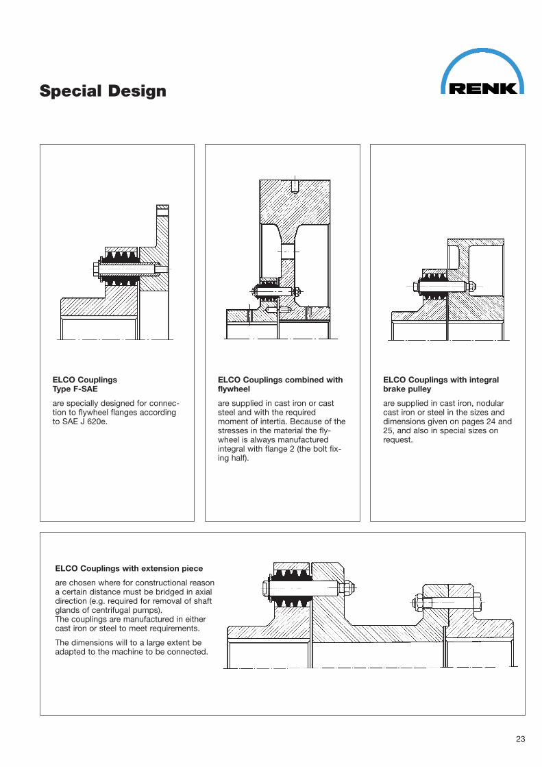
Special Design
ELCO Couplings with extension piece
are chosen where for constructional reasona certain distance must be bridged in axialdirection (e.g. required for removal of shaftglands of centrifugal pumps).The couplings are manufactured in eithercast iron or steel to meet requirements.
The dimensions will to a large extent beadapted to the machine to be connected.
ELCO CouplingsType F�SAE
are specially designed for connec�tion to flywheel flanges accordingto SAE J 620e.
ELCO Couplings combined withflywheel
are supplied in cast iron or caststeel and with the requiredmoment of intertia. Because of thestresses in the material the fly�wheel is always manufacturedintegral with flange 2 (the bolt fix�ing half).
ELCO Couplings with integralbrake pulley
are supplied in cast iron, nodularcast iron or steel in the sizes anddimensions given on pages 24 and25, and also in special sizes onrequest.
23
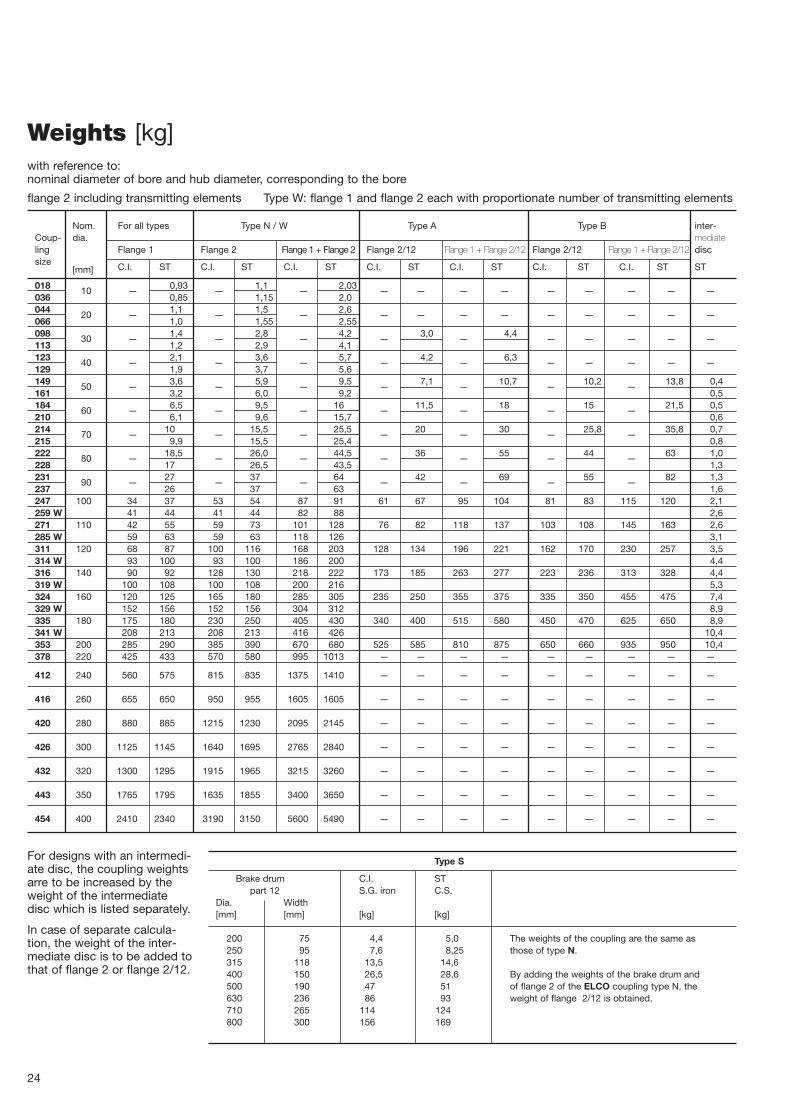
Weights [kg]
Nom. For all types Type N / W Type A Type B inter�Coup� dia. mediateling Flange 1 Flange 2 Flange 1 + Flange 2 Flange 2/12 Flange 1 + Flange 2/12 Flange 2/12 Flange 1 + Flange 2/12 discsize C.I. ST C.I. ST C.I. ST C.I. ST C.I. ST C.I. ST C.I. ST ST[mm]
018 10 — 0,93 — 1,1 — 2,03 — — — — — — — — —036 0,85 1,15 2,0044 20 — 1,1 — 1,5 — 2,6 — — — — — — — — —066 1,0 1,55 2,55098 30 — 1,4 — 2,8 — 4,2 — 3,0 — 4,4 — — — — —113 1,2 2,9 4,1123 40 — 2,1 — 3,6 — 5,7 — 4,2 — 6,3 — — — — —129 1,9 3,7 5,6149 50 — 3,6 — 5,9 — 9,5 — 7,1 — 10,7 — 10,2 — 13,8 0,4161 3,2 6,0 9,2 0,5184 60 — 6,5 — 9,5 — 16 — 11,5 — 18 — 15 — 21,5 0,5210 6,1 9,6 15,7 0,6214 70 — 10 — 15,5 — 25,5 — 20 — 30 — 25,8 — 35,8 0,7215 9,9 15,5 25,4 0,8222 80 — 18,5 — 26,0 — 44,5 — 36 — 55 — 44 — 63 1,0228 17 26,5 43,5 1,3231 90 — 27 — 37 — 64 — 42 — 69 — 55 — 82 1,3237 26 37 63 1,6247 100 34 37 53 54 87 91 61 67 95 104 81 83 115 120 2,1259 W 41 44 41 44 82 88 2,6271 110 42 55 59 73 101 128 76 82 118 137 103 108 145 163 2,6285 W 59 63 59 63 118 126 3,1311 120 68 87 100 116 168 203 128 134 196 221 162 170 230 257 3,5314 W 93 100 93 100 186 200 4,4316 140 90 92 128 130 218 222 173 185 263 277 223 236 313 328 4,4319 W 100 108 100 108 200 216 5,3324 160 120 125 165 180 285 305 235 250 355 375 335 350 455 475 7,4329 W 152 156 152 156 304 312 8,9335 180 175 180 230 250 405 430 340 400 515 580 450 470 625 650 8,9341 W 208 213 208 213 416 426 10,4353 200 285 290 385 390 670 680 525 585 810 875 650 660 935 950 10,4378 220 425 433 570 580 995 1013 — — — — — — — — —
412 240 560 575 815 835 1375 1410 — — — — — — — — —
416 260 655 650 950 955 1605 1605 — — — — — — — — —
420 280 880 885 1215 1230 2095 2145 — — — — — — — — —
426 300 1125 1145 1640 1695 2765 2840 — — — — — — — — —
432 320 1300 1295 1915 1965 3215 3260 — — — — — — — — —
443 350 1765 1795 1635 1855 3400 3650 — — — — — — — — —
454 400 2410 2340 3190 3150 5600 5490 — — — — — — — — —
24
with reference to:nominal diameter of bore and hub diameter, corresponding to the bore
flange 2 including transmitting elements Type W: flange 1 and flange 2 each with proportionate number of transmitting elements
For designs with an intermedi�ate disc, the coupling weightsarre to be increased by theweight of the intermediatedisc which is listed separately.
In case of separate calcula�tion, the weight of the inter�mediate disc is to be added tothat of flange 2 or flange 2/12.
Type S
Brake drum C.I. STpart 12 S.G. iron C.S.
Dia. Width[mm] [mm] [kg] [kg]
200 75 4,4 5,0 The weights of the coupling are the same as250 95 7,6 8,25 those of type N.315 118 13,5 14,6400 150 26,5 28,6 By adding the weights of the brake drum and 500 190 47 51 of flange 2 of the ELCO coupling type N, the630 236 86 93 weight of flange 2/12 is obtained.710 265 114 124800 300 156 169

25
Nom. For all types Type N / W Type A Type B Inter�Coup� dia. mediateling Flange 1 Flange 2 Flange 1 + Flange 2 Flange 2/12 Flange 1 + Flange 2/12 Flange 2/12 Flange 1 + Flange 2/12 discsize C.I. ST C.I. ST C.I. ST C.I. ST C.I. ST C.I. ST C.I. ST ST[mm]
018 10 — 0,00083 — 0,00096 — 0,0018 — — — — — — — — —036 0,00075 0,0013 0,00205044 20 — 0,00121 — 0,00166 — 0,00287 — — — — — — — — —066 0,00118 0,00172 0,0029098 30 — 0,00215 — 0,00414 — 0,00629 — 0,00405 — 0,0062 — — — — —113 0,00181 0,0042 0,00601123 40 — 0,00417 — 0,00691 — 0,01108 — 0,00775 — 0,01192 — — — — —129 0,00371 0,00703 0,01074149 50 — 0,01081 — 0,01738 — 0,02819 — 0,01975 — 0,03056 — 0,02675 — 0,03756 0,0014161 0,00940 0,01734 0,02674 0,0017184 60 — 0,02517 — 0,03772 — 0,0623 — 0,0435 — 0,06867 — 0,06 — 0,08517 0,0027210 0,02319 0,0378 0,061 0,0032214 70 — 0,0541 — 0,0859 — 0,14 — 0,105 — 0,1591 — 0,145 — 0,1991 0,0051215 0,0534 0,0853 0,1387 0,0057222 80 — 0,1488 — 0,2106 — 0,3594 — 0,235 — 0,3838 — 0,3525 — 0,5013 0,011228 0,1339 0,2132 0,3462 0,014231 90 — 0,2497 — 0,3885 — 0,6272 — 0,388 — 0,6377 — 0,548 — 0,7977 0,018237 0,2374 0,3910 0,6284 0,022247 100 0,4205 0,4592 0,6562 0,6615 1,0767 1,1207 0,7 0,725 1,12 1,185 0,938 0,993 1,3585 1,4522 0,035259 W 0,5059 0,5404 0,5059 0,5404 1,0117 1,0808 0,043271 110 0,6509 0,7939 0,997 1,0921 1,648 1,886 1,2 1,218 1,185 2,0119 1,625 1,7 2,2759 2,4939 0,058285 W 0,9127 0,95 0,9127 0,95 1,8254 1,9 0,069311 120 1,433 1,718 2,138 2,345 3,571 4,063 2,35 2,575 3,738 4,293 3,45 3,65 4,883 5,368 0,101314 W 1,971 2,003 1,971 2,003 3,943 4,006 0,126316 140 2,412 2,57 3,565 3,588 5,975 6,158 4,43 4,48 6,842 7,05 6,05 6,35 8,462 8,92 0,170319 W 2,636 2,992 2,636 2,992 5,272 5,984 0,204324
1604,018 4,413 5,39 6,224 9,408 10,64 7,63 7,83 11,65 12,24 11,6 12,1 15,61 16,51 0,341
329 W 5,095 5,39 5,095 5,39 10,19 10,78 0,409335 180 7,57 8,09 11,54 11,28 19,11 19,37 13,63 14,45 21,2 22,54 19,8 20,8 27,37 28,89 0,574341 W 8,996 9,52 8,996 9,52 17,99 19,04 0,669353 200 17,5 18,4 23,3 24,3 40,8 42,7 29,3 28,8 46,8 47,2 41,3 41,8 58,8 60,2 0,904378 220 33,6 35,4 45,6 47,6 79,2 83 — — — — — — — — —
412 240 54 57 79 83 133 140 — — — — — — — — —
416 260 76 79 110 114 186 193 — — — — — — — — —
420 280 122 127 170 177 292 304 — — — — — — — — —
426 300 174 182 252 269 427 451 — — — — — — — — —
432 320 221 227 330 348 551 575 — — — — — — — — —
443 350 349 349 334 383 683 783 — — — — — — — — —
454 400 577 577 787 812 1364 1400 — — — — — — — — —
For designs with intermediatedisc, the moment of inertia ofthe coupling is to be increasedby the moment of inertia ofthe intermediate disc which islisted separately.
In case of separate calcula�tion, the moment of inertia ofthe intermediate disc is to beadded to that of flange 2 orflange 2/12.
Type S
Brake drum C.I. Stpart 12 S.G. iron C.S.
Dia. Width[mm] [mm] [kgm2] [kgm2]
200 75 0,0355 0,0375 The moments of inertia of the coupling are the 250 95 0,100 0,108 same as those of type N.315 118 0,255 0,278400 150 0,800 0,863 By adding the moments of inertia of the brake 500 190 2,275 2,450 drum and of flange 2 of the ELCO coupling 630 236 6,500 7,000 type N, the moment of inertia of part 2/12 is 710 265 10,75 11,63 obtained.800 300 19,25 20,75
Moments of inertia [kgm2]with reference to:nominal diameter of bore and hub diameter, corresponding to the bore
flange 2 including transmitting elements Type W: flange 1 and flange 2 each with proportionate number of transmitting elements

Spare Parts
5 4,6 9 10 7 8Size No. Sleeve Transmitting pin Washer Circlip Grooved Nut
Seeger pinD L3) d l l1) l2) d1 s DIN 471
018 2036 4 19,8 25 8 51 — — 13 1,5 — ∅ 2,5 x 12 —044 5066 6
098 6113 8 24,8 30 10 62 — — 16 1,5 — ∅ 3 x 16 —123 8 62129 10
149 8161 10 31,5 38,5 12,8 88 102 104 24 2 13 x 1 — M 8814 10210 12
214 10 39,4 46,5 15,8 103,5 117,5 123,5 28 2,5 16 x 1 — M 8215 11
222 8228 10 49,3 54,6 19,8 123,5 139 143,5 38 3 20 x 1,2 — M 10231 10237 12
247 8 165259 W 10 62,3 64,6 24,8 147 — 172 48 3 25 x 1,2 — M 12271 10 165285 W 12 —
311 8 200,5314 W 10 79,2 78,7 32,8 181,5 — 206,5 62 4 33 x 1,5 — M 16316 10 200,5319 W 12 —
324 10 235329 W 12 99 94,8 40 213 — 243 76 4 40 x 1,75 — M 20335 12 235341 W 14 —
353 10 123,8 115 50 255 — 285 92 4 50 x 2 — M 20378 14
412 12416 14 158,5 143,5 63 316,5 — — 140 6 62 x 2 — M 30420 16
426 12432 14 198,2 179 80 395 — — 175 6 80 x 2,5 — M 36443 16454 18
26
Quality of sleeves: U W VColour mark of compr. sleeves: white yellow purple
1) execution S 2) For execution with intermediate disc 3) normal length (without preload)
Size 149 � 454Size 018 � 129
Colour mark Colour mark

27
Product Range
Plain Bearings
Type E for electrical machinery, fans, compressors, turbines Catalogue no. RH�1009
Type I for tube mill (e.g. cement manufacture) transmission units Catalogue no. RH�1120
Type M for general mechanical engineering applications Catalogue no. RH�1065
Type SN afermost bearings and intermediate bearings for shipbuilding applications Catalogue no. RH�1004
Type SC Radial bearing e.g. mounted to Diesel generators and rolling mill drives Catalogue no. RH�1149
Type HG for hydro generators and electric motors Catalogue no. RH�1188
Type WG Catalogue no. RH�1155
Type DN marine thrust blocks Catalogue no. RH�1073
Type VT and VG as complete thrust and guide bearings and guide bearings only Catalogue no. RH�1153
Type EV vertical bearing inserts for electrical machinery, fans and pumps Catalogue no. RH�1021
Type G Plain bearing shells Catalogue no. RH�1102
Type SH Trunnion bearings tube mills Catalogue no. RH�1147
RD Thrust Bearing Catalogue no. RH�1025
RS Thrust Pads Catalogue no. RH�1094
Special bearings RENK can design and manufacture special bearings for a wide range ofindustrial applications (e.g. type WG bearings with fabricated housingfor rolling mill drives)
Customer’s bearings RENK manufacture bearings, shells etc. to customer’s design and drawings
Couplings and Clutches
ELCO flexible compression sleeve coupling Catalogue no. RH�1008
ELBI flexible coupling for general mechanical engineering applications Catalogue no. RH� 076
AERO pneumatically shifted friction clutch Catalogue no. RH�1118
Centrifugal clutch Catalogue no. RH�1014
Overrunning clutch Catalogue no. RH�1013
Diaphragm clutch Catalogue no. RH�1063
Special couplings and clutches
Computer calculations available for plain bearings and couplings

RH
�100
8 (1
0.02
) Prin
ted
in G
erm
any
Sales Organisation
RENK AKTIENGESELLSCHAFTWerk HannoverWeltausstellungsallee 21D�30539 HannoverTelephone: +49 (5 11) 86 01�0Telefax: +49 (5 11) 86 01�288e�mail: gleitlager.hannover@renk�ag.comInternet: www.renk.de
We reserve the right to changes made in the interests of technical improvement.
Headquartersand Manufacturing Plant
RENK Corporation304, Tucapau Road29334 Duncan S.C.USATelephone: (1�8 64) 4330069Telefax: (1�8 64) 4330636
Assembly and Distribution Centerswith Sales and Engineering Support
MAN B&W (Japan) Ltd.RH Division; Fuji Building (Room 121)3�2�3 MarunouchiChiyoda�ku, Tokyo 100�0005JapanTelephone: (81�3) 3215 1310Telefax: (81�3) 3284 0867
Domestic + Export
Weltausstellungsallee 2130539 HannoverTelephone: +49 (5 11) 86 01�298 / �210Telefax: +49 (5 11) 86 01�288
Sales Agencies
Australia G.B. and Ireland NorwayAustria Hungary PR ChinaBelgium India Slovak RepublicBrazil Italy Slovenia RepublicCanada Japan South AfricaCzech Republic Liechtenstein South KoreaCroatia Luxembourg SpainFinland Mexico SwitzerlandFrance Netherlands USA
Related Documents