2014 Construction Products Catalog Innovative Fastening Technologies F l e x T e c h n o l o g y ® M e t a l F a s t e n i n g S y s t e m s C o n c r e t e A n c h o r i n g S y s t e m s B u i l d i n g P r o t e c t i o n

Welcome message from author
This document is posted to help you gain knowledge. Please leave a comment to let me know what you think about it! Share it to your friends and learn new things together.
Transcript
7/17/2019 Elco 2014 Catalog
http://slidepdf.com/reader/full/elco-2014-catalog 1/44
2014 Construction Products Catalog
Innovative Fastening Technologies
F l e x T e c h
n o l o g y ®
M e t
a l F a s t e n i n g S y s t e m s
C o n c r e t e A n
c h o r i n g S y s t e m
s
B u i l d i n g P r o t e
c t i o n

7/17/2019 Elco 2014 Catalog
http://slidepdf.com/reader/full/elco-2014-catalog 2/44

7/17/2019 Elco 2014 Catalog
http://slidepdf.com/reader/full/elco-2014-catalog 3/44
Design & Application AssistanceOur application specialistscan analyze your productdesigns and assist withoptimal fastener selectionThey can also offer designand material options.
Installation Analysis
Our commitment to you continues during andafter construction. If a problem should arise, ourapplications specialists are available to investigate anddetermine the cause.
Pricing, Availability and Ordering InformatioWith only a few exceptions, all the items in this cataloare considered stock items. As such, they are usuallyavailable for shipment within 24 hours. Many partsare also stocked at various strategic locations aroundthe United States to increase their accessibility.
For price and specific product availability, orto place an order, simply call 1-800-435-7213and ask for customer service. Elco ConstructionProducts only sells to authorized distributors.
Ordering Non-Stock Standard PartsWe recognize that all applications are unique andmay require fastening solutions that are notconsidered standard. Specials are considered anintegral part of what we offer to the marketplace.Because we offer such extensive manufacturing
capabilities, we can customize a fastener to meet thespecific needs of your application. A wide range ofsizes, materials, drive styles, head styles and moreare possible. Please contact a Customer ServiceRepresentative for assistance.
Special ServicesHead Painting: Virtually any color can be matched,using the highest quality paint available to maximizeadhesion and minimize chipping.
Packaging: In addition to the standard packaging
indicated in this catalog, alternative packaging optionare available ranging from bulk shipments in tubs tosmall-count poly bag packs.
To find the latest catalog information, learn about oucustom capabilities and services, or find design andother technical data, log ontowww.elcoconstruction.com.
A Commitment to theConstruction Industry
Elco Construction Products provides a broadrange of quality fasteners and value-addedservices designed to speed construction, improvebuilding integrity and ensure performance underdemanding conditions.
• Dril-Flex® structural drill screws that are virtually
immune to embrittlement failure
• Bi-Flex™ 300 series (18-8) stainless steel self-drillingscrews
• Drilltite® precision milled drill screws for greater drillconsistency
• Drilit® screws with forged self-drilling points in avariety of styles
• Alumi-Flex™ 300 series stainless steel self-drillingscrews
• UltraCon® masonry fasteners now available in blue,
silver, white or bronze Stalgard®
finish in 3/16", 1/4"and 5/16" diameters
• ConFlex® large diameter masonry fasteners
• Aggre-gator® 300 series (18-8) stainless steelbi-metal concrete anchors
• NEW Suspender™ dual-head threaded rodanchoring system
• Fab-Lok® clamping fasteners
In addition, many of the products shown in thiscatalog can be customized to meet the needs ofyour application.
We have attempted to make this catalog as completeand accurate as possible, but changes are inevitable.More part numbers and product lines will be addedon a regular basis. Visit our website for the mostup-to-date literature.
New Product DevelopmentOur close relationship with the construction industryhas led to many innovative products customizedfor specific applications. Our application engineerscan work directly with you to find solutions for yourparticular need.
Elco Construction Products701 E. Joppa Road • Towson MD 21286
Phone: 800-435-7213 (USA & Canada)
Fax: 563-387-3540
www.elcoconstruction.com

7/17/2019 Elco 2014 Catalog
http://slidepdf.com/reader/full/elco-2014-catalog 4/44

7/17/2019 Elco 2014 Catalog
http://slidepdf.com/reader/full/elco-2014-catalog 5/44
Drill Screws
Table of Contents
Stalgard® High-Performance Protective Coatings .................................
Drill Screw Technical Information ...........................................................
Standard Drill Screws ............................................................................1Drilit® Drill Screws with Bonded Sealing Washers ............................... 1
Drilit® Drill Screws for Wood-to-Metal Applications ........................... 1
Drill Screws with Extended Drilling Capacity ...................................... 1
Tapfast® Fasteners .................................................................................1
Architectural Roof Clip Fasteners ......................................................... 1 Technical Information ...................................................................... 1
Dril-Flex®
Structural Drill Screws ........................................................... 1 Technical Information ...................................................................... 1
Tap-Flex® Tapping Screws......................................................................1 Technical Information ...................................................................... 1
Bi-Flex™ Stainless Steel Bi-Metal Self-Drilling Screws ........................... 1 Technical Information ...................................................................... 2
Alumi-Flex™ 302 (18-8) Stainless Steel Drill Screws ..............................2
AllFlex™ 302 (18-8) Stainless Steel Screws .............................................2 Technical Information ...................................................................... 2
Fab-Lok® Fasteners ................................................................................2 Technical Information ...................................................................... 2
Avdel® N Rivets ......................................................................................2 Technical Information ...................................................................... 2
UltraCon® Masonry Fasteners ...............................................................2 Technical Information ...................................................................... 3
UltraCon SS4 Masonry Fasteners ..........................................................3
Crete-Flex
®
SS4 Masonry Fasteners ......................................................3 Technical Information ......................................................................34
Aggre-Gator® Stainless Steel Bi-Metal Concrete Anchors ................... 3 Technical Information ...................................................................... 3
ConFlex® Large Diameter Masonry Fasteners ......................................3 Technical Information ......................................................................3
HangerMate® Threaded Rod Anchoring System .................................39 Technical Information ...................................................................... 4
RapidSet® Tools ......................................................................................4

7/17/2019 Elco 2014 Catalog
http://slidepdf.com/reader/full/elco-2014-catalog 6/44

7/17/2019 Elco 2014 Catalog
http://slidepdf.com/reader/full/elco-2014-catalog 7/44
Stalgard® High-Performance Protective CoatingsProvide consistent, high corrosion resistance in construction applications
Stalgard® durable, multi-layer, corrosion-resistant coatings are engineered to provide optimal performance indemanding construction applications. These environmentally-friendly finishes are free of chromates and silicatesand any process, like electroplating, that might induce hydrogen embrittlement, preventing structural failures.
Stalgard SUBUltimate Barrier Coating
• For more severely-corrosive environments
• Salt spray 2,000 hours per ASTM B117
• Available color: Silver
• Maximizes fastener performance
• Salt spray at 1000+ hours with no red rust per ASTM B117
• Uniform thickness
• Low coefficient of friction – eliminates the need for post-coatinglubricants to ease installation
• Does not use processes that introduce hydrogen – will not causebrittle failures like those caused by electroplating
• Durable tough finish – doesn’t come off during handling or repeatedinstallations
• Clean and dry – no oily residue
• Eliminates the plating process, resulting in a more
environmentally-friendly product than those with plated zinc or otherfinishes
• Blue, grey, and white Stalgard are ACQ-compatible
• Maintains drilling and tapping performance
Stalgard GB(Galvanic Barrier) Coating
• Standard on all Elco stainless steel fasteners
• Prevents a galvanic reaction between the stainless steel and dissimilarapplication materials, which could lead to fastener and/or joint failure
• Salt spray resistance: 1000 hours per ASTM B117
•
Available color: Silver
RoHS compliant(chrome-free)
R oH S
2 0 0 2 / 9 5 / E C
.
C o m p l
i a n
t .
Stalgard Coating forInduction Heat-Treated Fasteners
• Proven, outstanding corrosion resistance for mostconstruction applications, including metal and wood
• Salt spray resistance: 1000 hours per ASTM B117• Available colors: silver, black, blue, white, yellow, red, gray and brown

7/17/2019 Elco 2014 Catalog
http://slidepdf.com/reader/full/elco-2014-catalog 8/44
NOTE: All performance data shown is based on tests performed under laboratory conditions at independent construction testing facilities. The appropriatesafety factor should be applied and code requirements factored into specification and use of these fasteners. A safety factor of 4:1 or 25% of the ultimateaverage values shown is generally accepted as an appropriate working load. Final determination of the appropriate safety factor and use of these fasteners
is the sole responsibility of the user, specifying Engineer, Architect or other responsible person designing the connection. Due to a wide variety ofapplication conditions or intervening factors not under our control, we assume no liability for the use of the information provided in this document.
For additional product information and technical assistance, please contact Elco directly at 1-800-435-7213.8
Drill ScrewsTechnical Information
Ultimate Strength Values†
Carbon Steel, Case Hardened Product
Size
TensileLbs.Min.
ShearAvg.Lbs.Ult.
TorqueMin.
In-Lbs.
8-18 1,615 1,100 428-32 1,890 1,228 48
10-16 2,200 1,470 61
10-24 2,362 1,535 65
12-14 2,950 1,960 92
12-24 3,400 2,275 100
1/4-14 3,850 2,580 150
1/4-20 4,276 2,860 168
5/16-12 7,650 5,100 250
5/16-18 8,903 5,247 438
11/32-12 8,550 5,700 400
23/64-12 9,150 6,100 425
Ultimate Average Fastener Pull-Out Values (Lbs)†
Descrip.PointType
Material Thickness
26Ga.
24ga.
22Ga.
20Ga.
18Ga.
16Ga.
14Ga.
12Ga. .120" 3/16" 1/4" 5/16" 3/8"
8-18 2 120 197 268 301 494 702 961 1,615 — — — — —
10-16 1 151 242 315 361 565 826 1,092 1,791 — — — — —
10-16 3 130 206 272 303 498 702 970 1,495 — — — — —
12-14 1 161 260 332 394 640 920 1,262 1,940 — — — — —
12-14 2 154 247 286 379 609 852 1,186 1,863 2,345 — — — —
12-14 3 142 214 296 349 580 767 1,078 1,553 1,956 — — — —
12-24 5 — — — 311 452 1,060 1,288 1,844 2,205 3,237 — — —
1/4-14 1 228 342 432 571 801 1,169 — — — — — — —
1/4-14 3 150 238 301 340 702 891 1,162 1,798 2,120 — — — —
1/4-20 3 — — — 337 571 1,232 1,525 2,212 2,447 4,066 — — —
1/4-20 5 — — — — — — — — 3,431 4,801 5,261 — —
5/16-123
(.260 dia.)— — — 491 706 1,609 1,707 2,831 2,915 3,745 — — —
5/16-183
(.290 dia.)— — — 457 568 1,209 1,712 2,422 2,601 3,716 5,122 5,288 —
14-10 SS A 270 363 426 459 657 1,194 1,368 — — — — — —
1/4-14 SS B 216 344 383 411 571 686 983 1,698 2,242 2,693 3,695 3,746 3,484
NOTE: SS = Stainless Steel; CS = Carbon Steel
Pull-Out
Shear
†NOTE: Test values shown are ultimate average values obtained under laboratory conditionsand apply to fasteners manufactured by Elco Construction Products only.
Desc. Pt.
Gauge 0.125(1/8")26 24 22 20 18 16 14 12
8-18 2 301 500 542 742 1,049 — — — —
10-16 1 403 585 673 883 1,330 — — — —
10-16 3 — 461 524 731 1,254 1,524 1,674 — —
12-14 1 437 718 763 1,030 1,548 — — — —
12-14 2 370 607 622 860 1,360 1,690 2,112 2,212 —
12-14 3 — — — 775 1,361 1,624 1,974 1,993 —
12-24 4 — — — — — 1,430 1,930 2,455 2,573
12-24 4.5 — — — — — 1,389 1,920 2,174 2,257
12-24 5 — — — — — 1,351 1,825 2,152 2,226
1/4-14 1 519 863 892 1,301 1,771 — — — —
1/4-14 3 — — — 930 1,447 2,102 2,584 2,650 —
1/4-20 5 — — — — — 1,655 2,277 — 3,210
Shear Values†
(Average Lbs. Ultimate)

7/17/2019 Elco 2014 Catalog
http://slidepdf.com/reader/full/elco-2014-catalog 9/44
NOTE: All performance data shown is based on tests performed under laboratory conditions at independent construction testing facilities. The appropriatesafety factor should be applied and code requirements factored into specification and use of these fasteners. A safety factor of 4:1 or 25% of the ultimateaverage values shown is generally accepted as an appropriate working load. Final determination of the appropriate safety factor and use of these fastenersis the sole responsibility of the user, specifying Engineer, Architect or other responsible person designing the connection. Due to a wide variety ofapplication conditions or intervening factors not under our control, we assume no liability for the use of the information provided in this document.
For additional product information and technical assistance, please contact Elco directly at 1-800-435-7213.
NominalScrew Sizes
ThreadDia. Decima
#6 .140
#7 .150
#8 .160
#9 .180
#10 .190
#11 .200
#12 .210
1/4 .240
#14 .250
Standard SheetMetal Sizes
Gauge Decimal
26 0.018
24 0.024
22 0.03020 0.038
18 0.048
16 0.060
14 0.075
12 0.106
Drill ScrewsTechnical Information
Point Size Selection
Maximum Combined Material Thickness By Point Type Recommended Installation RPM
Diameter RPM
#82500
#10
#121800
1/4"
5/16" 1200
† Lapped panels: 18 ga. to 18 ga.
* NOTE: Some drill and tap capacities may vary due to special features on somefasteners. Refer to product performance specifications for any individual fastener toconfirm performance and capabilities.
Drilling and Tapping Capacity (Maximum Material Thickness)*
ICC Evaluation Report ESR-3294

7/17/2019 Elco 2014 Catalog
http://slidepdf.com/reader/full/elco-2014-catalog 10/44
10 For product or ordering information, call 1.800.435.7213 (USA & Canada)
Standard Drill ScrewsSelf-drilling fasteners in the most popular sizes
Self-drilling fasteners eliminate separate drilling and tapping operations forfaster, more economical installations.
Specifications• Diameters: #8 to 5/16"
• Lengths: 1/2" to 4"
• Drill Points: Drilit® forged or Drilltite®
dual-processed• Drive Systems: Hex and phillips
• Material: Carbon steel
• Finishes: Stalgard® coating or zinc
Features & Benefits• Eliminates separate drilling and
tapping operations
• Fasteners coated with Stalgard finish
typically show no red rust or otherbase metal corrosion on significantsurfaces even after 1000 hours of5% neutral salt spray exposure (perASTM B117)
Catalog No. Description Point Type Finish Carton Quantity Weight/Carton
#8 Diameter, 1/4" Hex Washer Head
EDA236-I 8-18 x 1/2" #2 Drilit Stalgard 10,000 36
EDA261-I 8-18 x 3/4" #2 Drilit Stalgard 8,000 37
EDA286-I 8-18 x 1" #2 Drilit Stalgard 5,000 27
#8 Diameter, #2 Phillips Pan Head
EDD251-I 8-18 x 1/2" #2 Drilit Stalgard 10,000 34
EDD266-I 8-18 x 3/4" #2 Drilit Stalgard 10,000 44
EDD291 8-18 x 1" #2 Drilit Stalgard 8,000 43
#10 Diameter, 5/16" High Hex Washer Head
EDB401 10-16 x 1/2" #3 Drilit Stalgard 8,000 39
EDB426 10-16 x 5/8" #3 Drilit Stalgard 6,000 45
EDB446 10-16 x 3/4" #3 Drilit Stalgard 6,000 47
EFC460-I 10-16 x 3/4" #3 Drilit Zinc 6,000 47
EDC450 10-16 x 3/4" #1 Drilit Stalgard 5,000 39
EDB486 10-16 x 1" #3 Drilit Stalgard 5,000 46
EDB541 10-16 x 1-1/2" #3 Drilit Stalgard 3,000 35
EDB571 10-16 x 2" #3 Drilit Stalgard 2,000 29
#12 Diameter, 5/16" Hex Washer Head
EDC745 12-14 x 3/4" #1 Drilit Stalgard 5,000 45EDB741 12-14 x 3/4" #3 Drilit Stalgard 5,000 46
EDB761 12-14 x 1" #3 Drilit Stalgard 4,000 41
EDB782 12-14 x 1-1/4" #3 Drilit Stalgard 3,000 36
EDB801 12-14 x 1-1/2" #3 Drilit Stalgard 2,500 35
EDB821 12-14 x 2" #3 Drilit Stalgard 2,000 34
EDB840 12-14 x 3" #3 Drilit Stalgard 1,000 24
EDB845 12-14 x 4" #3 Drilit Stalgard 500 15
1/4" Diameter, 3/8" Hex Washer Head
EDB936 1/4-14 x 3/4" #3 Drilit Stalgard 3,500 48
EDC930 1/4-14 x 7/8" #1 Drilit Stalgard 4,000 38
EDB946 1/4-14 x 1" #3 Drilit Stalgard 3,000 47
EDB956 1/4-14 x 1-1/4" #3 Drilit Stalgard 2,000 37
EDB961 1/4-14 x 1-1/2" #3 Drilit Stalgard 2,000 39EDB971 1/4-14 x 2" #3 Drilit Stalgard 1,500 38
EDB981 1/4-14 x 3" #3 Drilit Stalgard 800 28
EDB983 1/4-14 x 4" #3 Drilit Stalgard 500 23
*
* denotes globally-sourced product.
7/17/2019 Elco 2014 Catalog
http://slidepdf.com/reader/full/elco-2014-catalog 11/44
1For product or ordering information, call 1.800.435.7213 (USA & Canada)
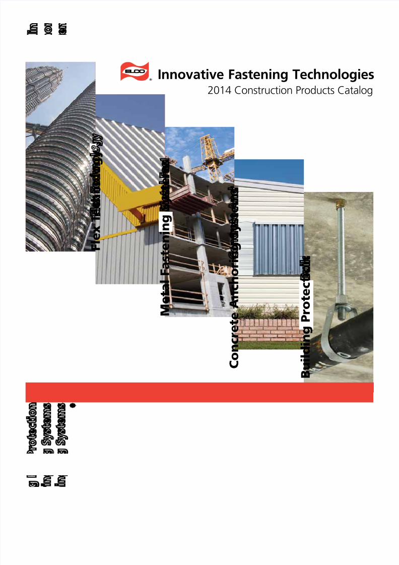
Drilit® Drill Screws with Bonded Sealing WashersEconomical fasteners for applications requiring a weather-tight seal
This economical line of drill screws provides a weather-tight seal for protectionagainst the elements.
Specifications• Diameters: #10 to 1/4"
• Lengths: 3/4" to 4"
• Head Styles: Hex washer
• Drive System: Hex• Point Types: #1 to #5
• Material: Carbon steel
• Finish: Stalgard® coating
Features & Benefits• EPDM washer material is
UV- and heat-resistant for long-termprotection
against leakage• Stalgard coating provides 1000 hours
of salt spray resistance (per ASTMB117)
Catalog No. Description Point Type Washer O.D. Finish Carton Quantity Weight/Carton
#10 Diameter, 5/16" Hex Washer Head
EHL111 10-16 x 3/4" #3 Drilit 1/2" Stalgard 4,000 31
EHL146 10-16 x 1-1/2" #3 Drilit 1/2" Stalgard 2,000 28
#12 Diameter, 5/16" Hex Washer Head
EHL165 12-14 x 3/4" #3 Drilit 9/16" Stalgard 3,000 34
EHL351 12-24 x 7/8 #4 Drilit 9/16" Stalgard 2,500 31
EHL181 12-14 x 1" #3 Drilit 9/16" Stalgard 2,500 32
EHL235 12-14 x 1-1/4" #3 Drilit 9/16" Stalgard 2,000 27
EHL371 12-24 x 1-1/4" #4.5 Drilit 9/16" Stalgard 2,500 39
EHL276 12-14 x 1-1/2" #3 Drilit 9/16" Stalgard 2,000 33
EHL280 12-14 x 2" #3 Drilit 9/16" Stalgard 1,500 30
EHL295 12-14 x 3" #3 Drilit 9/16" Stalgard 1,000 27
EHL310 12-14 x 4" #3 Drilit 9/16" Stalgard 500 15
ECW725 12-24 x 1-1/4" #5 Drilltite 9/16" Stalgard 2,500 35
ECW745 12-24 x 1-1/2" #5 Drilltite 9/16" Stalgard 2,000 28
ECW755 12-24 x 2" #5 Drilltite 9/16" Stalgard 1,000 20
1/4" Diameter, 3/8" Hex Washer Head
EHL515 1/4-14 x 3/4" #3 Drilit 5/8" Stalgard 2,500 40
EHK315 1/4-14 x 7/8" #1 Drilit 9/16" Stalgard 2,500 32
EHL530 1/4-14 x 1" #3 Drilit 5/8" Stalgard 2,000 37
EHL556 1/4-14 x 1-1/4" #3 Drilit 5/8" Stalgard 1,500 31
EHL577 1/4-14 x 1-1/2" #3 Drilit 5/8" Stalgard 1,500 34
EHL585 1/4-14 x 2" #3 Drilit 5/8" Stalgard 1,000 27
EHL600 1/4-14 x 3" #3 Drilit 5/8" Stalgard 800 29
EHL610 1/4-14 x 4" #3 Drilit 5/8" Stalgard 500 24
To assure a weather-tight seal, fasteners must be properly installed.
Correct Overdriven Underdriven

7/17/2019 Elco 2014 Catalog
http://slidepdf.com/reader/full/elco-2014-catalog 12/44
12 For product or ordering information, call 1.800.435.7213 (USA & Canada)
Cat.No. Dia. – TPI Len. Drive System Point.Size Max. Load-bearing Length Pieces per.1/4 Keg
Weight/1/4 Keg
Bi-Flex™ Bi-Metal 300 Series Stainless Steel Fasteners; Flat Head Reamers w/Wings
EBN140 10-16 1-1/2" #2 phillips 3 0.800" 3,500 30
EBN345 12-24 2-13/16" #3 phillips 5 1.710" 1,000 21
EBN645 1/4-20 2-13/16" #3 phillips 5 1.710" 1,000 28
Drilit® Drill Screws for Wood-to-Metal ApplicationsFor efficient fastening of wood or composite materials to steel
These self-drilling fasteners eliminate separate drilling and tapping operationsfor faster installation in wood-to-metal applications.
Specifications• Diameters: #10 to 1/4"
• Lengths: 3/4" to 3-15/16"
• Head Styles: Flat and wafer
• Drive System: Phillips• Point Styles: Types 3 and 4
• Material: Carbon steel
• Finishes: Gray Stalgard® coating
Features & Benefits• Eliminates pre-drilling of wood
• Broad selection of sizes
• Can be used with steel up to
5/16" thick• Gray Stalgard coating provides
1000 hours of salt spray resistance;developed for use with ACQ-treatedlumber with retention levels no higherthan .25 PCF
* NOTE: Some drill and tap capacities may vary due to
special features on some fasteners. Refer to productperformance specifications for any individual fastenerto confirm performance and capabilities.
** Bi-Flex fasteners only. See page 19 for details.
NOTE: Due to a wide variety of application conditions orintervening factors not under our control, we assume no liabilityfor the use of the information provided in this document. Foradditional product information and technical assistance, pleasecontact Elco directly at 1-800-435-7213.
Drilling and Tapping Capacity for Wood to MetalScrews (Maximum Material Thickness)*
Cat. No. Description Point Type FinishTypical Wood
ThicknessDrilling Capacity
(min. – max. in steel)Qty. PerShipper
Wt. PerShipper
#10 Diameter, #2 Phillips Wafer Head
EDM582 10-24 x 3/4" #3 Gray Stalgard 3/8" .036" – .187" 8,000 43
EDM592 10-24 x 1" #3 Gray Stalgard 1/2" .036" – .187" 6,000 43
EDM607 10-24 x 1-1/4" #3 Gray Stalgard 5/8" .036" – .187" 5,000 38EDT602 10-24 x 1-7/16" #3 w/wings Gray Stalgard 3/4" .036" – .187" 4,000 40
EDM622 10-16 x 1-1/2" #3 Gray Stalgard 3/4" .036" – .187" 3,500 35
EDM635 10-16 x 1-13/16" #3 Gray Stalgard 3/4" .036" – .150" 2,500 29
#12 Diameter, #3 Phillips Wafer Head
EDT720 12-24 x 1-3/4" #4 w/wings Gray Stalgard 1" .060" – .250" 2,000 29
#12 Diameter, #3 Phillips Flat Head
EDT267 12-24 x 2-1/4" #4 w/wings Gray Stalgard 1-1/4" .060" – .250" 2,000 32
EDT282 12-24 x 2-3/4" #4 w/wings Gray Stalgard 1-5/8" .060" – .250" 1,500 30
EDJ867 12-14 x 3-5/8" #2 w/pilot Gray Stalgard 1-3/4" .030" – .150" 1,000 24
1/4" Diameter, #3 Phillips Flat Head
EDT442 1/4-20 x 3" #4 w/wings Gray Stalgard 2" .060" – .250" 1,000 30
EDT470 1/4-20 x 4" #4 w/wings Gray Stalgard 3" .060" – .250"

7/17/2019 Elco 2014 Catalog
http://slidepdf.com/reader/full/elco-2014-catalog 13/44
1For product or ordering information, call 1.800.435.7213 (USA & Canada)
Drill Screws with Extended Drilling CapacitySpecially-designed drill points handle the toughest applications
This line of heavy-duty drill screws is designed to speed installation in steelapplications up to 1/2" thick.
Specifications• Diameters: #12 and 1/4"
• Lengths: 7/8" to 6"
• Head Style: Hex washer
• Drive System: Hex• Material: Carbon steel
• Finish: Silver Stalgard® coating
Features & Benefits• Points are either Drilit® forged or
Drilltite® precision milled points
• Can drill metal up to
0.500" thick• Stalgard coating provides
1000 hours of salt spray resistance(per ASTM B117)
NOTE: 1/4-20 drill screws with #5 points are available with bonded washers.
Catalog No. Description Point Type Finish Carton Quantity Carton Weight
#12 Diameter Decking Fasteners and Drill Screws for Steel Thicknesses of .175" to .500"
EDC801 12-24 x 7/8" #4 Drilit Stalgard 4,500 47
EDC816 12-24 x 1-1/4" #4.5 Drilit Stalgard 3,500 50
ECC720 12-24 x 1-1/4" #5 Drilltite Stalgard 4,000 45ECC740 12-24 x 1-1/2" #5 Drilltite Stalgard 2,500 40
ECC750 12-24 x 2" #5 Drilltite Stalgard 2,000 35
1/4" Diameter Decking Fasteners and Drill Screws for Steel Thicknesses of .175" to .500"
ECC940 1/4-20 x 3" #5 Drilit Stalgard 1,000 36
ECC950 1/4-20 x 4" #5 Drilit Stalgard 1,000 46
ECC960 1/4-20 x 5" #5 Drilit Stalgard 500 31
ECC970 1/4-20 x 6" #5 Drilit Stalgard 500 37
ECC980 1/4-20 x 8" #5 Drilit Stalgard 150 16

7/17/2019 Elco 2014 Catalog
http://slidepdf.com/reader/full/elco-2014-catalog 14/44
14 For product or ordering information, call 1.800.435.7213 (USA & Canada)
TapFast® FastenersFor use in metal-to-wood applications
High-performance fastener designed specifically for attaching light-gauge metalpanels (18 ga. max.) to wood frame structures.
Specifications• Size: #10
• Lengths: 1" to 3"
• Head/Drive: 1/4" HWH
• Thread: Hi-lo• Point: Type 17
• Material: Carbon steel
• Finish: Stalgard® coating
Features & Benefits• Aluminum bonded sealing washer
• High-low thread increasesperformance
• Easily penetrates multiple panelthicknesses
• Stalgard coating provides 1000 hoursof salt spray resistance(per ASTM B117)
Catalog No. Description Point Finish Carton Quantity Carton Weight
#9 Diameter, with Bonded Sealing Washer, Hex Washer Head
EHH210 10-16 x 1" Type 17 Stalgard 3,000 26
EHH230 10-16 x 1-1/2" Type 17 Stalgard 2,500 29
EHH250 10-16 x 2" Type 17 Stalgard 1,500 20EHH265 10-16 x 2-1/2" Type 17 Stalgard 1,000 17
EHH280 10-16 x 3" Type 17 Stalgard 800 16
Performance Data
Wood Type: SPF (Spruce, Pine or Fir) .38–.39 Specific Gravity
Pull-Out (Lbs.)
Force Orientation relative to wood's grain Edge Distance
Embedment (in.)
1" 1-1/2" 2"
With the grain (Into thin side) 3/4" 385 553 887
Against the grain (Into wide side) 1 1/2" 366 591 890Shear (Lbs.)
Force Orientation relative to wood's grain Edge Distance
Embedment (in.)
1" 1-1/2" 2"
With the grain (Into thin side) 3/4" 447 484 647
Against the grain (Into wide side) 1 1/2" 322 655 654
Wood Type: #2 SYP (Southern Yellow Pine) .57-.60 Specific Gravity
Pull-Out (Lbs.)
Force Orientation relative to wood's grain Edge Distance
Embedment (Inches)
1" 1-1/2" 2"
With the grain (Into thin side) 3/4" 1,118 1,647 1,947
Against the grain (Into wide side, near edge) 3/4" 1,220 1.572 1,806Shear (Lbs.)
Force Orientation relative to wood's grain Edge Distance
Embedment (Inches)
1" 1-1/2" 2"
With the grain (Into thin side) 3/4" 782 887 939
Against the grain (Into wide side, near edge) 3/4" 663 686 724
infastech/Elco Test Report Number 1002192

7/17/2019 Elco 2014 Catalog
http://slidepdf.com/reader/full/elco-2014-catalog 15/44
1For product or ordering information, call 1.800.435.7213 (USA & Canada)
Architectural Roof Clip FastenersLow-profile head design for wood and steel applications
The efficiency of self-drilling fasteners and the aethetics of an inobtrusive heaare ideal for attaching metal roof clips to metal and wood.
Specifications• Diameters: #10 to #12"
• Lengths: 1" to 2"
• Head Styles: Pancake
• Drive Systems: Phillips• Material: Carbon steel
• Finishes: Silver or grayStalgard® coating
Features & Benefits• Eliminates separate drilling and
tapping operations
• Pancake head improves aesthetics an
prevents panel dimpling• Stalgard coating provides 1000 hours
of salt spray resistance (per ASTMB117)
• Gray Stalgard is ACQ-compatible
Catalog No. Description Drive System Point Type Finish* Carton QuantityCartonWeight
For Steel
EDO450 10-16 x 1" #2 Phillips #3 Silver Stalgard 4.000 34
EDO460 10-16 x 1-1/2" #2 Phillips #3 Silver Stalgard 3,000 34
EDO470 10-16 x 2" #2 Phillips #3 Silver Stalgard 2,000 28
EDO735 12-14 x 1" #2 Phillips #3 Silver Stalgard 4,000 40
For Wood/Light Gauge Steel
ETA850 10-12 x 1" #2 Phillips Pierce Gray Stalgard 4,000 37
ETA855 10-12 x 1-1/2" #2 Phillips Pierce Gray Stalgard 3,000 33
ETA860 10-12 x 2" #2 Phillips Pierce Gray Stalgard 2,000 27
ETA870 12-11 x 1" #2 Phillips Pierce Gray Stalgard 4,000 40
Pull-Out Values (Lbs)
Diameter Point Type 26 ga. 24 ga. 22 ga. 20 ga. 18 ga. 14 ga. 12 ga.
#10 #3 139 206 272 303 498 970 1495
#12 #3 142 214 296 349 580 1078 1553
Diameter Point Type 1/2" Plywood 5/8" Plywood 3/4" Plywood Yellow Pine 3/4" OSB
#10 Pierce 366 381 401 582 290
#12 Pierce 378 393 429 677 329
Shear values (Lbs)
Diameter
Point
Type 20 ga. 18 ga. 16 ga. 14 ga.
#10 #3 301 503 710 969
#12 #3 775 1361 1624 1974
Performance Data
NOTE: All performance data shown is based on tests performed under laboratory conditions at independent construction testing facilities. The appropriatesafety factor should be applied and code requirements factored into specification and use of these fasteners. A safety factor of 4:1 or 25% of the ultimateaverage values shown is generally accepted as an appropriate working load. Final determination of the appropriate safety factor and use of thesefasteners is the sole responsibility of the user, specifying Engineer, Architect or other responsible person designing the connection. Due to a wide varietyof application conditions or intervening factors not under our control, we assume no liability for the use of the information provided in this document. Foradditional product information and technical assistance, please contact Elco directly at 1-800-435-7213.
* Gray Stalgard coating is ACQ-compatible

7/17/2019 Elco 2014 Catalog
http://slidepdf.com/reader/full/elco-2014-catalog 16/44
16 For product or ordering information, call 1.800.435.7213 (USA & Canada)
Dril-Flex® Structural Drill ScrewsVirtually immune to delayed embrittlement failures
Dual heat treated drill screws provide the strength, ductility and resistance toembrittlement required for critical applications.
Specifications• Diameters: #10 to 5/16"
• Lengths: 3/4" to 4"
• Head/Drive Styles: Hex washer and
phillips pan, wafer and undercut flat• Point Types: #3, #4 and #5
• Material: Alloy steel
• Heat Treat: Grade 5
• Finish: Silver Stalgard® orStalgard SUB coating
Features & Benefits• Stalgard SUB coating (Hex washer
product only) provides 2000 hours ofsalt spray resistance (per ASTM B117)
•
High-hardness points and lead threadsfor drilling and tapping withlower-hardness in load-bearingthreads for ductility
• Virtually immune to delayedembrittlement failures
* for aluminum applications only.
Catalog No. Description Pt.Load-Bearing
Area FinishCarton
QuantityCartonWeight
#10 Diameter, 5/16" Hex Washer Head
EAF430 10-16 x 3/4" #3 .380" Stalgard SUB 6,000 48
EAF460 10-16 x 1-1/2" #3 1.25" Stalgard SUB 2,500 30
EAF470 10-16 x 2" #3 1.50" Stalgard SUB 2,000 28
EAF480 10-16 x 2-1/2" #3 2.25" Stalgard SUB 1,500 25#10 Diameter, #2 Phillips Pan Head
EDX445 10-16 x 3/4" #2 .380" Stalgard 6,000 36#10 Diameter, #2 Phillips Wafer Head
EBL530 10-24 x 1-1/4" #3 .750" Stalgard 5,000 44
#12 Diameter, 5/16" Hex Washer Head
EAF621* 12-14 x 7/8" #3 .380" Stalgard SUB 5,000 54
EAF641 12-14 x 1" #3 .500" Stalgard SUB 4,000 44
EAF681 12-14 x 1-1/2" #3 1.00" Stalgard SUB 2,500 38
EAF690 12-14 x 2" #3 1.50" Stalgard SUB 2,000 37
EAF715 12-14 x 3" #2 2.35" Stalgard SUB 1,000 27
#12 Diameter, #3 Phillips Undercut Flat Head
EBL215 12-14 x 1" #3 .500" Stalgard 4,000 36EBL223 12-14 x 1-1/2 #3 1.00" Stalgard 2,500 26
1/4" Diameter, 3/8" Hex Washer Head
EAF816 1/4-14 x 1" #3 .450" Stalgard SUB 3,000 54
EAF841 1/4-14 x 1-1/2" #3 .950" Stalgard SUB 2,000 45
EAF876 1/4-20 x 1-1/2" #4 .830" Stalgard SUB 2,000 48
EAF846 1/4-14 x 2" #3 1.45" Stalgard SUB 1,500 41
EAF886 1/4-20 x 2" #4 1.33" Stalgard SUB 1,500 45
EAF865 1/4-20 x 1-1/8" #4 .500" Stalgard SUB 2,500 51
EAF888 1/4-20 x 1-3/4" #5 .800" Stalgard SUB 1,000 27
EAF890 1/4-20 x 2-1/2" #4 1.83" Stalgard SUB 1,000 45
EAF900 1/4-20 x 3-3/8" #4 2.70" Stalgard SUB 500 22
EAF910 1/4-20 x 4" #4 3.50" Stalgard SUB 500 23
1/4" Diameter, #3 Phillips Undercut Flat HeadEBL330 1/4-20 x 3" #4 2.50" Stalgard 500 20
EBL340 1/4-20 x 4" #4 3.50" Stalgard 500 235/16" Diameter, 3/8" Hex Washer Head
EAF940 5/16-18 x 1-1/2" #3 .800" Stalgard SUB 1,000 37
EAF960 5/16-24 x 1-1/2" #4 .800" Stalgard SUB 1,000 40
EAF970 5/16-24 x 2" #4 1.25" Stalgard SUB 1,000 49
3/8" Diameter, 3/8" Hex Washer Head
EAF310 3/8-16 x 1-3/4" #1 .850" Stalgard SUB 500 18
Load-Bearing Area:
Hex WasherHead
UndercutHead
Pan Head
Wafer Head
7/17/2019 Elco 2014 Catalog
http://slidepdf.com/reader/full/elco-2014-catalog 17/44
NOTE: All performance data shown is based on tests performed under laboratory conditions at independent construction testing facilities. The appropriatesafety factor should be applied and code requirements factored into specification and use of these fasteners. A safety factor of 4:1 or 25% of the ultimateaverage values shown is generally accepted as an appropriate working load. Final determination of the appropriate safety factor and use of these fastenersis the sole responsibility of the user, specifying Engineer, Architect or other responsible person designing the connection. Due to a wide variety ofapplication conditions or intervening factors not under our control, we assume no liability for the use of the information provided in this document.
For additional product information and technical assistance, please contact Elco directly at 1-800-435-7213. 1
(hex washer head shown)
raised circleElco® logo
ScrewSize
PointType
DrillCap.
Steel
18-18ga.
18-14ga.
16-16ga.
14-14ga.
1/8"-3/16"
3/16"-1/4"
1/4"-12 ga.
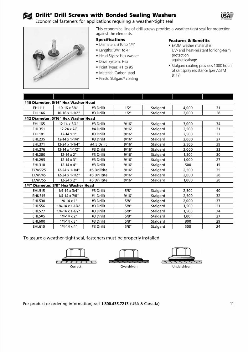
10-16 3 .150 1362 1733 1462
12-14 3 .187 1315 2118 1655 1816
1/4-14 3 .210 1395 2313 1681 2417 2600
1/4-20 4 .312 1350 2086 1582 2450 2814 2810 2706
5/16-18 3 .210 1509 2300 1811 3255
5/16-24 4 .312 5486 5283 4761
3/8-16 1 .075 6750
Shear Tests – Steel: Shear values shown are in lbs.
NOTE: All test setups and dimensions were as limited and outlined in AISI Test Method for Mechanically Fastened Cold-Formed SteelConnections (CF92-1) document. Performance values listed are ultimate values obtained under laboratory conditions.
Shear Tests – Aluminum
Pull-out Tests – AluminumPull-out Tests – Steel: Pull-out values shown are in lbs.
Embrittlement testing of Dril-Flex screwswas performed in accordance toASTM F1624-06. Fastener lots were testedto determine their Threshold Stress Limitsfor both Internal Hydrogen Embrittlementand Environmental Hydrogen Embrittlement.Threshold Stress Limit is the stress level belowwhich no time-dependent cracking will occu
Above this level, subcritical cracking that leadto time-delayed fracture or embrittlementmay occur if the fastener is exposed to ahydrogen environment.
Embrittlement Test Results• Dril-Flex fasteners have a hardness range of
HRC 28 – 34, which is roughly equivalent to aSAE Grade 5 fastener (HRC 25 – 34).
• Dril-Flex fasteners showed resistance to theeffect of hydrogen-assisted cracking whenloaded to 75% of their tensile strength. This iwithin accepted industry guidelines forin-service loading conditions.
• Dril-Flex fasteners showed no degradation orfailures in tensile strength below their ultimattensile strength.
300 series stainless steel fastenersprovide high resistance to hydrogenembrittlement failures. However,stainless steel is galvanicallyincompatible with aluminum orsteel panels. In this case,stainless steel fasteners trigger asacrificial action, which can lead
to degradation of the panel andloosening of the fastener.
A dual-hardening process allowsDril-Flex® fasteners to provide highstrength and resistance to hydrogenembrittlement failures. TheirStalgard® finish provides corrosionresistance several times greater thanother commonly-used finishes. If an environment is corrosive enoughto significantly affect the Stalgard finish, the potential for significantdegradation of the aluminum/stainless steel assembly would also exist.
Comparison to Stainless Steel Screws Embrittlement Tests
Dril-Flex® Structural Drill ScrewsTechnical Information
Approvals• ICC-ES Report No. ESR-3332
• COLA (City of Los Angeles) Research Report #25095
Identification
ScrewSize
PointType
DrillCap.
Aluminum 6063-T5
1/8" 1/4" 3/8"
10-16 3 .150
12-14 3 .187 939 2286
1/4-14 3 .210 1003 2424
1/4-20 4 .312 897 2075 3683
5/16-18 3 .210 1120 2967 47965/16-24 4 .312 1043 2566
ScrewSize
PointType
DrillCap.
Aluminum 6063-T5
1/8" - 1/8" 1/8" - 1/4"
10-16 3 .150 1466
12-14 3 .187 1797 2483
1/4-14 3 .210 1996 2883
1/4-20 4 .312 2006 2926
5/16-18 3 .210 2132 3009
5/16-24 4 .312 1849 2926
ScrewSize
PointType
DrillCap.
Steel
18 16 14 12 1/8 3/16 1/4 5/16
10-16 3 .150 396 501 634 1595 1693
12-14 3 .187 396 527 710 1678 2061 2898
1/4-14 3 .187 398 530 686 1950 2264 3919
1/4-20 4 .312 516 649 1912 2296 2928 3561 4488
5/16-18 3 .210 2333 28565/16-24 4 .312 2148 2573 4226 5424 6622
3/8-16 1 .075 1843
Galvanic Series
Anodic End
Metal/Alloy EMF(v)
Magnesium................................ -1.60
Zinc............................................. -1.10
Alum (5000, 6000, 7000)........... -.75
Iron, Low Alloy Steels................ -.70
Alum (2000)............................... -.60
Lead............................................ -.5518% Chromium Steel................. -.35
Naval Brass................................. -.30
Brass, Bronze.............................. -.25
Austenitic Stainless (300 Series) -.20
Nickel.......................................... -.15
Silver........................................... 0
Gold............................................+15
Cathodic End

7/17/2019 Elco 2014 Catalog
http://slidepdf.com/reader/full/elco-2014-catalog 18/44
18 For product or ordering information, call 1.800.435.7213 (USA & Canada)
Tap-Flex™ Thread-Forming Structural ScrewsIncreased thread engagement with strength and ductility
Specifications• Diameters: 3/8", 1/2", and 5/8"
• Head Style: Hex washer
• Threads: E-Form® five-lobethread forming
• Material: Alloy steel• Finish: Silver Stalgard® SUB coating
• Heat Treat: Grade 5; meets ASTMA449 specifications (120 KSI strength)
Feature a unique thread profile to ease installation and increase performance.
Size Catalog No. FinishLoad-Bearing
Length Quantity Weight
3/8" Diameter, Hex Washer Head
3/8-16 x 1-1/2 ESU310 Stalgard SUB 1.00" 500 34
3/8-16 x 2 ESU320 Stalgard SUB 1.49" 500 40
3/8-16 x 2-1/2 ESU330 Stalgard SUB 1.99" 500 46
1/2" Diameter, Hex Washer Head
1/2-13 x 1-1/2 ESU410 Stalgard SUB 0.875" 250 36
1/2-13 x 2 ESU420 Stalgard SUB 1.365" 250 41
1/2-13 x 2-1/2 ESU430 Stalgard SUB 1.865" 250 47
5/8" Diameter, Hex Washer Head
5/8-11 x 1-1/2 ESU510 Stalgard SUB 0.800" 250 46
5/8-11 x 2 ESU520 Stalgard SUB 1.24" 150 33
5/8-11 x 2-1/2 ESU530 Stalgard SUB 1.74" 150 38
E-Form® Profile
Features and Benefits• E-Form thread overcomes friction
build-up and reduces drive torque
• Roll forms own work-hardened threadto resist loosening and provide
enhanced pull-out values• Virtually immune to delayed
embrittlement failures
• Stalgard SUB coating provides 2000hours of salt spray resistance (perASTM B117)
raisedcircle
Elco® logo
Identification
Seating Torque (inlbs)
FastenerSize
6063 T5 Aluminum 6061 T6 Aluminum 6063 T5 on 1018 Steel 6061 T6 on 1018 Steel1/8 3/16 1/4 1/8 3/16 1/4 1/8 3/16 1/4 3/8 1/8 3/16 1/4 3/8
3/8-16 171 214 285 231 328 490 412 638 805 858 389 581 740 771
1/2-13 255 368 471 338 547 767 558 955 1375 1895 513 807 1189 1658
5/8-11 261 486 662 343 694 943 654 1258 1662 2976 600 1061 1492 2083
Note: These numbers were calculated from the maximum reading (failure torque) during drive-to-fail testing (Seating Torque = FailureTorque x .75).
Shear (Ultimate lbs)
FastenerSize
6063 T5 Aluminum 6061 T6 Aluminum 6063 T5 to 1018 Steel 6061 T6 to 1018 Steel
1/8 to1/8
3/16 to3/16
1/4 to1/4
1/8 to1/8
3/16 to3/16
1/4 to1/4
1/8 to1/8
3/16 to3/16
1/4 to1/4
1/4 to3/8
1/8 to1/8
3/16 to3/16
1/4 to1/4
1/4 to3/8
3/8-16 2321 3476 4979 3560 5205 6885 5015 6560 6975 6965 5711 8701 7721 7611
1/2-13 2784 3669 5230 4482 6167 8718 4773 6455 8396 8689 6052 9769 13976 13340
5/8-11 2696 3775 5455 4216 6768 9292 4558 6196 8290 8060 5967 9577 13124 15309
Pull Out (Ultimate lbs)
FastenerSize
6063 T5 Aluminum 6061 T6 Aluminum 1018 Steel
1/8 3/16 1/4 1/8 3/16 1/4 1/8 3/16 1/4 3/8
3/8-16 1311 2365 3281 2080 3805 5981 3501 5986 11440 11862
1/2-13 1431 2230 3694 2190 3869 7527 3668 7411 13613 20440
5/8-11 1755 2907 4191 2641 5202 8210 4500 8300 16678 26680
Performance Data

7/17/2019 Elco 2014 Catalog
http://slidepdf.com/reader/full/elco-2014-catalog 19/44
For product or ordering information, call 1.800.435.7213 (USA & Canada)
Bi-Flex™ 300 Series Stainless Steel Bi-Metal Self-Drilling ScrewsBi-metal technology provides outstanding corrosion resistance and long service life
Bi-Flex™ fasteners provide the corrosion resistance of 300 series stainless steeland the efficiency of drillscrews.
Specifications• Diameters: #10 to 1/4"
• Lengths: 3/4" to 8"
• Drive Systems: Hex and phillips
• Material: Hardened steel tappingthreads and point fused ontoan 18-8 stainless steel shankand head
• Finish: Stalgard® GB(Galvanic Barrier) coating
* The load-bearing length is the length of 300 series stainless under the hex, pan or pancake head or including the flathead. Hardened steel length (lead threads and point) should be through the connection and not in the load bearingsection of the connection.
CatalogNo. Dia. – TPI
LLength
DriveSystem
PointSize
BMaximum Load-bearing Length*
Piecesper
1/4 Keg
Weightper
1/4 Keg
Hex Washer Head
EAJ100 8-18 3/4" 5/16" hex 2 0.32" 5,000 23
EAJ102 8-18 1" 5/16" hex 2 0.50" 5,000 27EAJ110 10-16 3/4" 5/16" hex 2 0.32" 5,000 32
EAJ120 10-16 1" 5/16" hex 2 0.50" 5,000 46
EAJ140 10-16 1-1/2" 5/16" hex 2 1.10" 2,500 39
EAJ185 12-14 1" 5/16" hex 2 0.50" 3,000 31
EAJ215 12-14 1-1/2" 5/16" hex 2 1.00" 2,500 34
EAJ190 12-14 1" 5/16" hex 3 0.50" 4,000 41
EAJ220 12-14 1-1/2" 5/16" hex 3 1.00" 2,500 34
EAJ260 12-14 2-1/2" 5/16" hex 3 2.00" 1,000 21
EAJ240 12-14 2" 5/16" hex 2 1.50" 1,500 26
EAJ320 12-24 1-1/2 5/16" hex 5 0.60" 2,500 40
EAJ340 12-24 2" 5/16" hex 5 1.10" 2,000 35
EAJ415 1/4-14 1" 3/8" hex 2 0.50" 2,500 40EAJ430 1/4-14 1-1/2" 3/8" hex 2 1.00" 1,000 30
EAJ445 1/4-14 2" 3/8" hex 2 1.50" 1,500 25
EAJ540 1/4-20 1" 3/8" hex 3 0.50" 2,500 40
EAJ580 1/4-20 1-1/2" 3/8" hex 3 1.00" 1,000 32
EAJ600 1/4-20 1-1/2" 3/8" hex 5 0.60" 1,000 32
EAJ610 1/4-20 2" 3/8" hex 3 1.50" 1,500 38
EAJ615 1/4-20 2" 3/8" hex 5 1.10" 1,500 38
EAJ640 1/4-20 2-1/2" 3/8" hex 3 2.00" 1,000 32
EAJ650 1/4-20 3" 3/8" hex 3 2.50" 500 18
EAJ630 1/4-20 3" 3/8" hex 5 2.10" 500 18
EAJ660 1/4-20 4" 3/8" hex 3 3.50" 500 22
EAJ670 1/4-20 4" 3/8" hex 5 3.10" 500 23EAJ675 1/4-20 5" 3/8" hex 5 4.10" 250 16
EAJ680 1/4-20 6" 3/8" hex 5 5.10" 250 18
EAJ690C 1/4-20 8" 3/8" hex 5 7.10" 150 15
Features & Benefits• High strength, ductility and reliability
• Virtually immune to delayedembrittlement failures
•Greater galvanic compatibility indissimilar metal applicationsinvolving aluminum
• High in-place value over the lifeof application

7/17/2019 Elco 2014 Catalog
http://slidepdf.com/reader/full/elco-2014-catalog 20/44
20 For product or ordering information, call 1.800.435.7213 (USA & Canada)
CatalogNo. Dia. – TPI
LLength
DriveSystem
PointSize
BMaximum Load-bearing Length*
Piecesper
1/4 Keg
Weightper
1/4 Keg
Flat Head Reamers w/wings
EBN140 10-16 1-1/2" #2 phillips 3 0.800" 3,500 30
EBN345 12-24 2-13/16" #3 phillips 5 1.710" 1,000 21
EBN645 1/4-20 2-13/16" #3 phillips 5 1.710" 1,000 28
Flat Head Undercut
EBN200 12-14 1" #3 phillips 2 0.500" 4,000 31
EBN240 12-14 1-1/2" #3 phillips 2 1.00" 2,500 29
EBN630 1/4-20 3" #3 phillips 2 2.500" 500 18
EBN640 1/4-20 4" #3 phillips 2 3.500" 500 22
Pan Head
EAX100 8-18 3/4" #2 phillips 2 0.320" 5,000 22
EAX102 8-18 1" #2 phillips 2 0.500" 5,000 27
EAX110 10-16 3/4" #2 phillips 2 0.320" 5,000 30
EAX120 10-16 1" #2 phillips 2 0.500" 5,000 37
Pancake Head
EBN300 10-16 1" #2 phillips 2 0.500" 4,000 29
EBN320 12-14 1" #2 phillips 3 0.500" 4,000 40
Bi-Flex™ 300 Series Stainless Steel Bi-Metal Self-Drilling ScrewsOrdering and Technical Information
IdentificationThe head marking consists of thenumber “3” above the Elco® logo asshown to the left.flat, pan and
pancake headhex washer
head
* The load-bearing length is the length of 300 series stainless under the hex, pan or pancake head or including the flathead. Hardened steel length (lead threads and point) should be through the connection and not in the load bearing
section of the connection.
7/17/2019 Elco 2014 Catalog
http://slidepdf.com/reader/full/elco-2014-catalog 21/44
NOTE: All performance data shown is based on tests performed under laboratory conditions at independent construction testing facilities. The appropriatesafety factor should be applied and code requirements factored into specification and use of these fasteners. A safety factor of 4:1 or 25% of the ultimateaverage values shown is generally accepted as an appropriate working load. Final determination of the appropriate safety factor and use of these fastenersis the sole responsibility of the user, specifying Engineer, Architect or other responsible person designing the connection. Due to a wide variety ofapplication conditions or intervening factors not under our control, we assume no liability for the use of the information provided in this document.
For additional product information and technical assistance, please contact Elco directly at 1-800-435-7213.
Ultimate Strengths**
Size
Tensile
(Lbs)
Shear
Average Lbs Ultimate10-16 1847 1282
12-14 2628 1950
12-24 2734 2284
1/4-14 3459 2676
1/4-20 4124 2860
** Values are for 300 series stainless fastener threaded shank
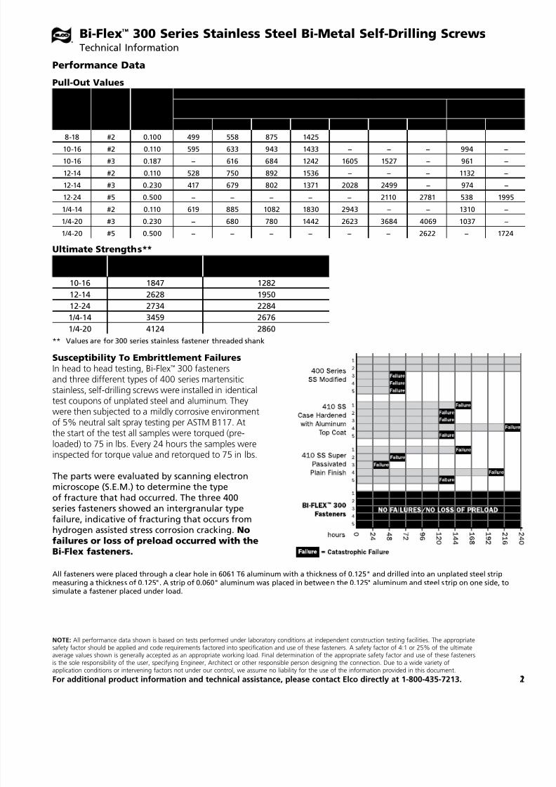
Performance Data
Bi-Flex™ 300 Series Stainless Steel Bi-Metal Self-Drilling ScrewsTechnical Information
All fasteners were placed through a clear hole in 6061 T6 aluminum with a thickness of 0.125" and drilled into an unplated steel stripmeasuring a thickness of 0.125". A strip of 0.060" aluminum was placed in between the 0.125" aluminum and steel strip on one side, tosimulate a fastener placed under load.
Susceptibility To Embrittlement FailuresIn head to head testing, Bi-Flex™ 300 fastenersand three different types of 400 series martensiticstainless, self-drilling screws were installed in identicaltest coupons of unplated steel and aluminum. They
were then subjected to a mildly corrosive environmentof 5% neutral salt spray testing per ASTM B117. Atthe start of the test all samples were torqued (pre-loaded) to 75 in lbs. Every 24 hours the samples wereinspected for torque value and retorqued to 75 in lbs.
The parts were evaluated by scanning electronmicroscope (S.E.M.) to determine the typeof fracture that had occurred. The three 400series fasteners showed an intergranular typefailure, indicative of fracturing that occurs fromhydrogen assisted stress corrosion cracking. Nofailures or loss of preload occurred with the
Bi-Flex fasteners.
Pull-Out Values
ScrewSize Pt.
DrillCapacity
(in.)
Pull-Out (Lbs)
Steel RB60-7550 – 66KSI
Aluminum 6063-T522KSI
18 ga. 16 ga. 14 ga. 12 ga. 1/8" 3/16" 1/4" 1/8" 1/4"
8-18 #2 0.100 499 558 875 1425
10-16 #2 0.110 595 633 943 1433 − − − 994 −
10-16 #3 0.187 − 616 684 1242 1605 1527 − 961 −
12-14 #2 0.110 528 750 892 1536 − – − 1132 −
12-14 #3 0.230 417 679 802 1371 2028 2499 − 974 −
12-24 #5 0.500 − − − − − 2110 2781 538 1995
1/4-14 #2 0.110 619 885 1082 1830 2943 – − 1310 −
1/4-20 #3 0.230 − 680 780 1442 2623 3684 4069 1037 –
1/4-20 #5 0.500 − − − − − − 2622 − 1724

7/17/2019 Elco 2014 Catalog
http://slidepdf.com/reader/full/elco-2014-catalog 22/44
22 For product or ordering information, call 1.800.435.7213 (USA & Canada)
Catalog No. Description Point Type Finish Carton Quantity Carton Weight
#10 Diameter Hex Washer Head
EAH430 10-16 x 1/2" #3 Stalgard GB 8,000 51
EAH445 10-16 x 3/4" #3 Stalgard GB 6,000 46
EAH460 10-16 x 1" #3 Stalgard GB 5,000 45
#10 Diameter, Undercut Flat HeadEBM160 10-16 x 3/4" #3 Stalgard GB 10,000 44
#12 Diameter Hex Washer Head
EAH630 12-14 x 3/4" #3 Stalgard GB 5,000 40
EAH650 12-14 x 1" #3 Stalgard GB 5,000 52
EAH680 12-14 x 1-1/2" #3 Stalgard GB 3,000 44
1/4" Diameter Hex Washer Head
EAH800 1/4-14 x 3/4" #3 Stalgard GB 3,500 51
EAH820 1/4-14 x 1" #3 Stalgard GB 3,000 48
EAH835 1/4-14 x 1-1/2" #3 Stalgard GB 2,000 41
EAH870 1/4-20 x 1" #4 Stalgard GB 2,000 35
EAH880 1/4-20 x 1-1/2" #4 Stalgard GB 2,000 42
1/4" Diameter, Undercut Flat Head
EBM260 1/4-14 x 3/4" #3 Stalgard GB 4,500 42
Alumi-Flex™ 302 (18-8) Stainless Steel Drill ScrewsFor fastening to aluminum when corrosion is a primary concern
Stainless steel drill screws provide strength and corrosion resistance in avariety of aluminum applications.
Specifications• Diameters: #10 to 1/4"
• Lengths: 1/2" to 1-1/2"
• Head Style: Hex washer
• Drive System: Hex• Point Types: #3 and #4
• Material: 302 stainless steel
• Finish: Stalgard® GB(Galvanic Barrier) coating
Features & Benefits• Provides a very high level of corrosion
resistance
• Coating allows greater galvanic
compatibility in dissimilar metalapplications involving aluminum
• Head marked with a “3” for easyidentification
Note: For aluminum applications only.IdentificationThe head marking consists ofthe number “3” below theElco® logo.
flathead
hex washerhead
Tensile Strength (Mechanical Characteristics)
Size Pt.
Peak Load (Lbs. of Force) PSI
Yield(Fy)
Ultimate(Fu)
Yield(Fy)
Ultimate(Fu)
#10-16 3 1,766 1,778 93,937 94,580
#12-14 3 2,300 2,320 93,268 94,061
1/4-14 3 3,180 3,197 97,888 98,433
1/4-20 4 3,225 3,266 101,438 102,709
Shear (Lbs. of Force)Lapped 6061 T6 Aluminum Strips
Size Pt. .060" .090" .125" .187" .250" .312"
Ult. ShearStrength of
Fastener
#10-16 3 834 1,275 1,306 – – – 1,152
#12-14 3 668 1,611 1,692 1,744 – – 1,545
1/4-14 3 769 1,963 2,255 2,275 – – 2,122
1/4-20 4 – 1,794 2,163 2,176 2,244 2,244 2,139
Elco test #1002278 Date: 8/21/2013
Pull-Out (Lbs. of Force)6061 T6 Aluminum
Size Pt. .060" .090" .125" .187" .250" .312"
#10-16 3 341 849 1,460 – – –
#12-14 3 347 859 1,533 2360*2 – –
1/4-14 3 386 955 1,657 3205*1 3227*2 –
1/4-20 – – 1,208 1,846 3291*2 3289*2 3299*2
Mode of Failure KeyUnless noted, the MOF was Material Failure in all test samples*1: 3 Test samples had material failure and seven samples had
fastener failure*2: Fastener failure in all test samples
7/17/2019 Elco 2014 Catalog
http://slidepdf.com/reader/full/elco-2014-catalog 23/44
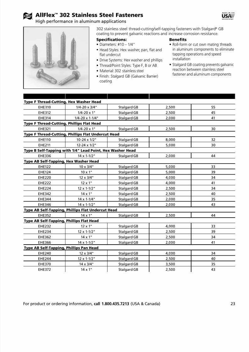
2For product or ordering information, call 1.800.435.7213 (USA & Canada)
Catalog No. Description Finish Carton Quantity Carton Weight
Type F Thread-Cutting, Hex Washer Head
EHE310 1/4-20 x 3/4" Stalgard GB 2,500 55
EHE312 1/4-20 x 1" Stalgard GB 2,500 45
EHE314 1/4-20 x 1-1/4" Stalgard GB 2,000 41
Type F Thread-Cutting, Phillips Flat Head
EHE321 1/4-20 x 1" Stalgard GB 2,500 30
Type F Thread-Cutting, Phillips Flat Undercut Head
EHE110 10-24 x 1/2" Stalgard GB 8,000 32
EHE211 12-24 x 1/2" Stalgard GB 5,000 30
Type B Self-Tapping with 1/4" Lead Point, Hex Washer Head
EHE336 14 x 1-1/2" Stalgard GB 2,000 44
Type AB Self-Tapping, Hex Washer Head
EHE122 10 x 3/4" Stalgard GB 5,000 33
EHE124 10 x 1" Stalgard GB 5,000 39
EHE220 12 x 3/4" Stalgard GB 4,000 34
EHE222 12 x 1" Stalgard GB 4,000 41EHE224 12 x 1-1/2" Stalgard GB 2,500 34
EHE342 14 x 1" Stalgard GB 2,500 40
EHE344 14 x 1-1/4" Stalgard GB 2,000 35
EHE346 14 x 1-1/2" Stalgard GB 2,000 43
Type AB Self-Tapping, Phillips Flat Undercut Head
EHE352 14 x 1" Stalgard GB 2,500 44
Type AB Self-Tapping, Phillips Flat Head
EHE232 12 x 1" Stalgard GB 4,000 33
EHE234 12 x 1-1/2" Stalgard GB 2,500 39
EHE362 14 x 1" Stalgard GB 2,500 34
EHE366 14 x 1-1/2" Stalgard GB 2,000 41
Type AB Self-Tapping, Phillips Pan Head
EHE240 12 x 3/4" Stalgard GB 4,000 34
EHE244 12 x 1-1/2" Stalgard GB 2,500 40
EHE370 14 x 3/4" Stalgard GB 3,500 35
EHE372 14 x 1" Stalgard GB 2,500 43
AllFlex™ 302 Stainless Steel FastenersHigh performance in aluminum applications
302 stainless steel thread-cutting/self-tapping fasteners with Stalgard® GBcoating to prevent galvanic reactions and increase corrosion resistance.
Specifications:• Diameters: #10 – 1/4"
• Head Styles: Hex washer, pan, flat andflat undercut
•
Drive Systems: Hex washer and phillips• Thread/Point Styles: Type F, B or AB
• Material: 302 stainless steel
• Finish: Stalgard GB (Galvanic Barrier)coating
Benefits• Roll-form or cut own mating threads
in aluminum components to eliminattapping operations and speedinstallation
• Stalgard GB coating prevents galvanireaction between stainless steelfastener and aluminum components

7/17/2019 Elco 2014 Catalog
http://slidepdf.com/reader/full/elco-2014-catalog 24/44
NOTE: All performance data shown is based on tests performed under laboratory conditions at independent construction testing facilities. The appropriatesafety factor should be applied and code requirements factored into specification and use of these fasteners. A safety factor of 4:1 or 25% of the ultimateaverage values shown is generally accepted as an appropriate working load. Final determination of the appropriate safety factor and use of these fasteners
is the sole responsibility of the user, specifying Engineer, Architect or other responsible person designing the connection. Due to a wide variety ofapplication conditions or intervening factors not under our control, we assume no liability for the use of the information provided in this document.
For additional product information and technical assistance, please contact Elco directly at 1-800-435-7213.24
Thread and Point Styles Head Styles & Identification
Type F Type Bwith lead
TypeAB
Hex Washer Phillips FlatUndercut
Phill ips Pan Phillips Flat
Thread/ Point Head Style Screw Dia.
UltimateYield
UltimateTensile
UltimateShear
Screw MaterialKSI
Type F
Hex Washer 1/4 3203 3274 2259 103
Flat 1/4 2945 3203 2123 101
Undercut Flat #10 1717 1839 1222 105
Undercut Flat #12 2243 2322 1604 96Type B Hex Washer #14 3038 3233 2249 99
Type AB
Hex Washer #10 1602 1616 1165 86
Hex Washer #12 2386 2399 1639 97
Hex Washer #14 3033 3187 2228 98
Undercut Flat #14 2819 3217 2230 99
Flat #12 1916 2130 2230 86
Flat #14 1916 2130 2230 86
Pan #12 2819 3217 2230 99
Pan #14 2819 3217 2230 99
AllFlex™ 302 Stainless Steel FastenersTechnical Information
Performance Data
AllFlex™ headmarking

7/17/2019 Elco 2014 Catalog
http://slidepdf.com/reader/full/elco-2014-catalog 25/44
2For product or ordering information, call 1.800.435.7213 (USA & Canada)
Ultimate Shear (lbs)
Screw Material
Carbon Stainless
2159 1950
Pull-Out (lbs)
Single Sheet
Material Thickness Pull-Out Failure Mode
26 ga. 612 Sheet Split
24 ga. 776 Sheet Split
20 ga. 888 Sheet Split
18 ga. 934 Sheet Split
16 ga. 1011 Broken Fastener
14 ga. 1069 Broken Fastener
Double Steel Sheet
Material Thickness Pull-Out Failure Mode
26 ga. 816 Sheet Split
20 ga. 1084 Broken Fastener
Double Aluminum Sheet
Material Thickness Pull-Out Failure Mode
0.032" 833 Broken Fastener
Fab-Lok® FastenersTo maintain panel integrity in high-stress and high-vibration environments
Vibration, either from inside or outside a building, can make ordinary fastenersloosen and back out. Fab-Lok fasteners combine a slotted aluminum sleeveand fastener to provide high resistance to vibration loosening. Excellent foruse with insulated panels.
Specifications• Drive System: Hex
• Materials: Low carbon steel or 300series stainless steel screw withaluminum sleeve
• Finish: Zinc
Features & Benefits• Hex washer head machine screw
assembled to a slotted aluminum sleeveand EPDM sealing washer
• After tightening, clamping tines remainin place even if screw is removed
• Greater joint integrity withclamping force
*Fab-Lok fastener is inserted into a 5/16" hole (hole size is not critical) then installedwith a power driver equipped with a Fab-Lok holding sleeve, with a socket designed tofit DeWalt® tools DW969K-2, DW968K-2, DW267, DW268 and DW269. Max. 1000 RPM
during installation.
before installation
after installation
can be easily used in blind applications
Head Marking Designation
Catalog No. DescriptionPenetrating
Length Grip RangeCarton
Quantity Carton Weight
Carbon Steel
EZJ100 FAS-10-4 1.373" .062" – .250" 1,000 22
EZJ120 FAS-10-8 1.612" .250" – .500" 1,000 23
EZJ140 FAS-10-12 1.807" .500" – .750" 1,000 27
H3 (300 Series) Stainless Steel
EZJ210 FAC-10-4 1.373" .062" – .250" 1,000 21
EZJ230 FAC-10-8 1.612" .250 "– .500" 1,000 25
EZJ250 FAC-10-12 1.807" .500" – .750" 1,000 27
Fab-Lok Drive Tools*
EZJ900 Holding Sleeve with Socket 1
Carbon steel screw: 4dots in horizontal line
Stainless steel screw”F” above ”2”

7/17/2019 Elco 2014 Catalog
http://slidepdf.com/reader/full/elco-2014-catalog 26/44
26 For product or ordering information, call 1.800.435.7213 (USA & Canada)
Specifications• Diameters: 1/8", 5/32" and 3/16"
• Lengths: .275" to .980"
• Grip ranges: .020" to .750"
• Body/Mandrel material: – Aluminum/Aluminum
– Steel/Steel
– Aluminum/Steel
– Stainless/Stainless
Features and Benefits• High quality with low in-place cost
• Vibration resistant
• Tamper-resistant
• Long grip ranges• High pull out and shear strengths
• Works with all hand andbattery tooling
• Custom painting available
Avdel® N RivetsProtruding head nail rivets for metal to metal applications
The N Rivet relies on a unique mandrel head design to complete the application joint and ensure positive stem retention after installation.
All Aluminum Protruding Head
SizeBulk
Cat. No.BulkQty.
42 AAPS-04-02 10,000
43 AAPS-04-03 10,000
44 AAPS-04-04 10,00045 AAPS-04-05 10,000
46 AAPS-04-06 10,000
48 AAPS-04-08 10,000
52 AAPS-05-02 8,000
54 AAPS-05-04 8,000
56 AAPS-05-06 8,000
58 AAPS-05-08 8,000
62 AAPS-06-02 5,000
64 AAPS-06-04 5,000
66 AAPS-06-06 5,000
68 AAPS-06-08 5,000
610 AAPS-06-10 4,000612 AAPS-06-12 4,000
All Steel Protruding Head
SizeBulk
Cat. No.BulkQty.
42 SSPS-04-02 10,000
43 SSPS-04-03 10,000
44 SSPS-04-04 10,00045 SSPS-04-05 10,000
46 SSPS-04-06 10,000
48 SSPS-04-08 10,000
54 SSPS-05-04 5,000
56 SSPS-05-06 5,000
62 SSPS-06-02 4,000
64 SSPS-06-04 4,000
66 SSPS-06-06 4,000
68 SSPS-06-08 3,000
610 SSPS-06-10 3,000
612 SSPS-06-12 3,000
Aluminum/Steel Protruding Head
SizeBulk
Cat. No.BulkQty.
42 BSPS-04-02 10,000
43 BSPS-04-03 10,000
44 BSPS-04-04 10,000
45 BSPS-04-05 10,000
46 BSPS-04-06 10,000
48 BSPS-04-08 10,00054 BSPS-05-04 5,000
56 BSPS-05-06 5,000
62 BSPS-06-02 5,000
64 BSPS-06-04 4,000
66 BSPS-06-06 4,000
68 BSPS-06-08 3,000
610 BSPS-06-10 3,000
612 BSPS-06-12 3,000
All Stainless Protruding Head
SizeBulk
Cat. No.BulkQty.
42 CCPS-04-02 10,000
43 CCPS-04-03 10,000
44 CCPS-04-04 10,000
45 CCPS-04-05 10,000
46 CCPS-04-06 10,000
54 CCPS-05-04 5,00056 CCPS-05-06 5,000
62 CCPS-06-02 4,000
64 CCPS-06-04 4,000
66 CCPS-06-06 4,000
68 CCPS-06-08 4,000

7/17/2019 Elco 2014 Catalog
http://slidepdf.com/reader/full/elco-2014-catalog 27/44
NOTE: All performance data shown is based on tests performed under laboratory conditions at independent construction testing facilities. The appropriatesafety factor should be applied and code requirements factored into specification and use of these fasteners. A safety factor of 4:1 or 25% of the ultimateaverage values shown is generally accepted as an appropriate working load. Final determination of the appropriate safety factor and use of these fastenersis the sole responsibility of the user, specifying Engineer, Architect or other responsible person designing the connection. Due to a wide variety ofapplication conditions or intervening factors not under our control, we assume no liability for the use of the information provided in this document.
For additional product information and technical assistance, please contact Elco directly at 1-800-435-7213.
Size Grip Range Hole Size
42 .063 - .125
#30
(.1285")
43 .126 - .187
44 .188 - .250
45 .251 - .31246 .313 - .375
48 .438 - .500
Avdel® N RivetsProtruding head nail rivets for metal to metal applications
Size Grip Range Hole Size
52 .020 - .125
#20(.161")
53 .126 - .187
54 .126 - .250
56 .251 - .37558 .376 - ..500
Size Grip Range Hole Size
62 .020 - .125
#11
(.191")
64 .126 - .250
66 .251 - .375
68 .376 - .500610 .501 - .625
612 .626 - .750
Grip Ranges and Recommended Hole Size
Shear and Tensile Values
Diameter Body Mandrel Shear Tensile
1/8" Aluminum Aluminum 120 150
1/8" Steel Steel 260 310
1/8" Aluminum Steel 170 220
1/8" Stainless Stainless 420 530
5/32" Aluminum Aluminum 190 230
5/32" Steel Steel 370 470
5/32" Aluminum Steel 260 350
5/32" Stainless Stainless 650 820
3/16" Aluminum Aluminum 260 320
3/16" Steel Steel 540 680
3/16" Aluminum Steel 380 500
3/16" Stainless Stainless 950 1200
N RivetPlacementSequence
Head Styles
Protruding Countersunk Large Flang
breakergroove
mandrel
mandrelhead
rivetbody
head(protruding
shown)
Installation Tools
Cat. No. Description
G-28Hand riveter for 1/8" and3/16” diameter rivets
728A9-104Additional nose piece for5/32" diameter rivets

7/17/2019 Elco 2014 Catalog
http://slidepdf.com/reader/full/elco-2014-catalog 28/44
28 For product or ordering information, call 1.800.435.7213 (USA & Canada)
Boxed Anchors100 anchors and 1 tanged drill bit per box; 6 boxes per carton.
Cat. No.
Size Drive SystemQuantity
Per ShipperWeight
Per ShipperBlue Stalgard
Slotted Hex Washer Head
ELE300-100 3/16 x 1-1/4" 5/16 hex with slot 600 5ELE310-100 3/16 x 1-3/4" 5/16 hex with slot 600 7
ELE320-100 3/16 x 2-1/4" 5/16 hex with slot 600 8
ELE330-100 3/16 x 2-3/4" 5/16 hex with slot 600 10
ELE340-100 3/16 x 3-1/4" 5/16 hex with slot 600 11
ELE350-100 3/16 x 3-3/4" 5/16 hex with slot 600 13
ELE360-100 3/16 x 4" 5/16 hex with slot 600 13
ELE405-100 1/4 x 1-1/4" 5/16 hex with slot 600 9
ELE415-100 1/4 x 1-3/4" 5/16 hex with slot 600 12
ELE425-100 1/4 x 2-1/4" 5/16 hex with slot 600 14
ELE435-100 1/4 x 2-3/4" 5/16 hex with slot 600 16
ELE445-100 1/4 x 3-1/4" 5/16 hex with slot 600 19
ELE455-100 1/4 x 3-3/4" 5/16 hex with slot 600 21ELE465-100 1/4 x 4" 5/16 hex with slot 600 22
ELE475-100 1/4 x 5" 5/16 hex with slot 100 5
ELE485-100 1/4 x 6" 5/16 hex with slot 100 6
Phillips Flat Head
ELF305-100 3/16 x 1-1/4" #2 phillips 600 4
ELF315-100 3/16 x 1-3/4" #2 phillips 600 6
ELF325-100 3/16 x 2-1/4" #2 phillips 600 7
ELF335-100 3/16 x 2-3/4" #2 phillips 600 9
ELF345-100 3/16 x 3-1/4" #2 phillips 600 10
ELF355-100 3/16 x 3-3/4" #2 phillips 600 12
ELF365-100 3/16 x 4" #2 phillips 600 13
ELF400-100 1/4 x 1-1/4" #3 phillips 600 8ELF410-100 1/4 x 1-3/4" #3 phillips 600 10
ELF420-100 1/4 x 2-1/4" #3 phillips 600 12
ELF430-100 1/4 x 2-3/4" #3 phillips 600 14
ELF440-100 1/4 x 3-1/4" #3 phillips 600 16
ELF450-100 1/4 x 3-3/4" #3 phillips 600 18
ELF460-100 1/4 x 4" #3 phillips 600 19
ELF470-100 1/4 x 5" #3 phillips 100 4
ELF480-100 1/4 x 6" #3 phillips 100 5
UltraCon® Masonry Fastening SystemOffers optimal performance in concrete, brick and hollow block applications
UltraCon anchors are available in a variety of styles to meet your needs.
Specifications• Diameters: 3/16" to 5/16"
• Head Styles: Hex washer, flat,hex flange, TrimFit® hex andTrimFit flat
• Drive Systems: Hex and phillips• Material: Carbon steel
• Finishes: Blue, silver, and whiteStalgard® coating standard; bronzeavailable upon request. Blue andwhite Stalgard are ACQ-compatible.
Features & Benefits• Installs quickly when using Elco®
installation tools
• When all three elements of thesystem are used, consistent
performance and maximum pull-outstrengths can be realized
• Stalgard coating provides1000 hours of salt spray resistance(per ASTM B117)

7/17/2019 Elco 2014 Catalog
http://slidepdf.com/reader/full/elco-2014-catalog 29/44
2For product or ordering information, call 1.800.435.7213 (USA & Canada)
UltraCon® Masonry FastenersOffers optimal performance in concrete, brick and hollow block applications
Cat. No.
Size Drive SizeQuantityPer Case
WeightPer Case
SilverStalgard
WhiteStalgard
BronzeStalgard
Slotted Hex Washer Head
ELG341 ELD195 – 1/4 x 1-3/4" 5/16 hex with slot 2,000 38
ELG371 ELD205 – 1/4 x 2-1/4" 5/16 hex with slot 1,500 34ELG401 ELD215 – 1/4 x 2-3/4" 5/16 hex with slot 1,000 27
ELG431 ELD225 – 1/4 x 3-1/4" 5/16 hex with slot 1,000 31
– ELD235 – 1/4 x 3-3/4" 5/16 hex with slot 500 16
– ELD255 – 1/4 x 5" 5/16 hex with slot 500 22
– ELD265 – 1/4 x 6" 5/16 hex with slot 500 26
Phillips Flat Head
ELG521 ELD320 – 3/16 x 1-1/4" #2 phillips 5,000 35
ELG551 ELD330 – 3/16 x 1-3/4" #2 phillips 3,000 28
ELG581 ELD340 – 3/16 x 2-1/4" #2 phillips 2,500 29
ELG611 ELD350 – 3/16 x 2-3/4" #2 phillips 1,500 21
ELG641 ELD360 – 3/16 x 3-1/4" #2 phillips 1,000 16
ELG671 ELD370 – 3/16 x 3-3/4" #2 phillips 1,000 19
– ELD380 – 3/16 x 4" #2 phillips 1,000 12
ELG941 – – 5/16 x 2-1/4" #3 phillips 1,000 34
ELG948 – – 5/16 x 2-3/4" #3 phillips 1,000 41
ELG960 – – 5/16 x 3-1/4" #3 phillips 500 24
ELG979 – – 5/16 x 4" #3 phillips 500 29
ELG992 – – 5/16 x 5" #3 phillips 500 16
ELG998 – – 5/16 x 6" #3 phillips 500 21
Phillips Oversized Flat Head – Door Frame Anchor
ELG203-50 5/16 x 3" #3 phillips 50 22
ELG204-50 5/16 x 4" #3 phillips 50 29
ELG205-50 5/16 x 5" #3 phillips 50 16
ELG206-50 5/16 x 6" #3 phillips 50 21Hex Flange Head (5/8" O.D.)
ELC145 ELD275 – 1/4 x 1-3/4" 5/16 hex 1,500 36
ELC151 ELD285 – 1/4 x 2-1/4" 5/16 hex 1,000 28
ELC160 ELD295 – 1/4 x 2-3/4" 5/16 hex 1,000 32
ELC170 ELD305 – 1/4 x 3-1/4" 5/16 hex 500 18
Hex Head with Oversized Washer (.540" O.D.)
ELG481 – – 5/16 x 1-3/4" 5/16 hex 1,000 30
ELG486 – – 5/16 x 2-1/4" 5/16 hex 1,000 37
ELG491 – – 5/16 x 2-3/4" 5/16 hex 800 22
ELG496 – – 5/16 x 3-1/4 5/16 hex 500 25
ELG501 – – 5/16 x 3-3/4" 5/16 hex 500 29ELG506 – – 5/16 x 4" 5/16 hex 500 30
ELG511 – – 5/16 x 5" 5/16 hex 250 18
ELG516 – – 5/16 x 6" 5/16 hex 250 22
TrimFit® Hex Head (.415 nom. washer O.D.)
ELG482 – – 5/16 x 1-3/4" 5/16 hex 1,500 44
ELG487 – – 5/16 x 2-1/4" 5/16 hex 1,000 36
ELG492 – – 5/16 x 2-3/4" 5/16 hex 1,000 43
ELG497 – – 5/16 x 3-1/4" 5/16 hex 500 25
ELG502 – – 5/16 x 3-3/4" 5/16 hex 500 28
Bulk Anchors

7/17/2019 Elco 2014 Catalog
http://slidepdf.com/reader/full/elco-2014-catalog 30/44
30 For product or ordering information, call 1.800.435.7213 (USA & Canada)
UltraCon® Masonry Fastening SystemOffers optimal performance in concrete, brick and hollow block applications
Installation Tools
Carbide-Tipped Tanged Drill Bits*
Cat No. Description
ForAnchor
Size
Qty.Per
Tube
ELT300-010 5/32 x 3-1/2 3/16" 10
ELT310-010 5/32 x 4-1/2 3/16" 10
ELT320-010 5/32 x 5-1/2 3/16" 10
ELT405-010 3/16 x 3-1/2 1/4" 10
ELT415-010 3/16 x 4-1/2 1/4" 10
ELT425-010 3/16 x 5-1/2 1/4" 10ELT435-010 3/16 x 6-1/2 1/4" 10
ELT445-010 3/16 x 7-1/2 1/4" 10
ELT460-005 1/4 x 4-1/2 5/16" 5
ELT465-005 1/4 x 5-1/2 5/16" 5
ELT475-005 1/4 x 7-1/2 5/16" 5
Cat. No.
Size Drive SizeQuantityPer Case
WeightPer Case
SilverStalgard
WhiteStalgard
BronzeStalgard
TrimFit® Flat Head (.415" nom. O.D.)
– – ELG612 3/16 x 2-3/4" #3 phillips 1,500 21
ELG771 ELD400 – 1/4 x 1-3/4" #3 phillips 2,000 32ELG801 ELD410 – 1/4 x 2-1/4" #3 phillips 1,500 30
ELG831 ELD420 ELG832 1/4 x 2-3/4" #3 phillips 1,000 24
ELG861 ELD430 ELG862 1/4 x 3-1/4" #3 phillips 1,000 28
ELG891 ELD440 ELG892 1/4 x 3-3/4" #3 phillips 500 16
ELG921 ELD450 – 1/4 x 4" #3 phillips 500 17
ELG945 – – 5/16 x 2-1/4" #3 phillips 1,500 47
ELG955 – – 5/16 x 2-3/4" #3 phillips 1,000 38
ELG965 – – 5/16 x 3-1/4" #3 phillips 500 22
ELG972 – – 5/16 x 3-3/4" #3 phillips 500 26
ELG976 – – 5/16 x 4" #3 phillips 500 27
ELG991 – – 5/16 x 5" #3 phillips 250 17
Hex-collared SDS Carbide-tippedDrill Bits**
* For use with hammer drill guns. 5/32 and3/16" sold in tubes containing 10 bits each;1/4" bits sold in tubes containing 5 bits each.
Cat No. Description
ForAnchor
Size
Qty.Per
Shipper
ELT535-010 5/32 x 5 x 2 3/16" 10
ELT555-010 5/32 x 7 x 4 3/16" 10
ELT630-010 3/16 x 5 x 2 1/4" 10
ELT650-010 3/16 x 7 x 4 1/4" 10
**For use with with rotary hammer drills and
1000 installation tools. One drill bit per tube.
Cat. No. Description Qty. Wt.
ELP100 1000 Tool Kit 1 4
includes:
ELY100 Drill Adapter 1 –
ELY110Drive Sleeve
Assembly1 –
ELY120 5/16" Hex Socket 1 –
ELY1251/4" Hex DriveSocket for 1/4"
Anchor1 –
ELY1301/4" Hex Socketfor 3/16" Anchor
1 –
ELY140 #2 Phillips Bit 1 –
ELY150 #3 Phillips Bit 1 –
ELY160 Phillips Bit Holder 1 –
ELY210 Set Screw 1 –
ELY220 1/8" Hex Key 1 –
also available:
ELY170
8" Drive SleeveAssembly for 5"and 6" UltraCon
Anchors
1
Bulk Anchors, continued

7/17/2019 Elco 2014 Catalog
http://slidepdf.com/reader/full/elco-2014-catalog 31/44
NOTE: All performance data shown is based on tests performed under laboratory conditions at independent construction testing facilities. The appropriatesafety factor should be applied and code requirements factored into specification and use of these fasteners. A safety factor of 4:1 or 25% of the ultimateaverage values shown is generally accepted as an appropriate working load. Final determination of the appropriate safety factor and use of these fastenersis the sole responsibility of the user, specifying Engineer, Architect or other responsible person designing the connection. Due to a wide variety ofapplication conditions or intervening factors not under our control, we assume no liability for the use of the information provided in this document.
For additional product information and technical assistance, please contact Elco directly at 1-800-435-7213. 3
NOTE: Indicated pull-out and shear failure values were obtained in tests witnessed by independent test labs (see below). These figures ar
offered only as a guide and are not guaranteed in any way by Elco Construction Products.
Performance Data
Dia.
Hollow Block1,924 PSI
Concrete2,730 PSI Wood
Depth ofEmbed.
EdgeDistance Pull-out Shear
Depth ofEmbed.
EdgeDistance Pull-out Shear
Depth ofEmbed.
EdgeDistance Pull-out Shear
3/16" 1-1/4"
1" 421 546
1"
1"
422 692 – – – –
1-3/8" 884 782 – – – –
1-3/4" 1,096 856 – – – –
2-1/2" 427 575
1"
2-1/2"
444 639 – – – –
1-3/8" 750 866 – – – –
1-3/4" 1,271 781 – – – –
1/4" 1-1/4"
1" 998 900
1"
1"
668 632 – – – –
1-3/8" 1,166 1,070 – – – –
1-3/4" 1,857 919 – – – –
2-1/2" 709 1,486
1"
2-1/2"
809 1,153 – – – –
1-3/8" 1,507 1,583 – – – –
1-3/4" 1,908 1,780 – – – –
Hollow Block1,872 PSI
Concrete3,513 PSI
Wood #2 SYPSpecific Gravity .55
5/16" 1-1/4"
1- 9/16" 1,049 708
1"1-1/4"
737 879 1"
5d
1,423 1,095
1-3/4" 2,105 1,324 1-1/2" 2,471 1,617
1" 2-3/16" 836 1,500 2" 2,912 2,367
3-1/8" 1,149 1,454
1-3/4" 2-3/16" 2,413 3,158 – – – –
1"
3-1/8"
851 1,801 1"
10d
1,454 1,188
1-3/4" 2,643 3,404 1-1/2" 2,472 1,677
2" 3,347 – 2" 3,233 2,407
Concrete
UltraCon Dia. Test report no.*
3/16" HETI 03-1127
1/4" HETI 03-1136
5/16" HETI 01-5013
* Testing by HurricaneEngineering & Testing, Inc.(HETI).
Additional testing has beendone in other materials andconditions and is availableupon request.
Block
UltraCon Dia. Test report no.*
3/16" HETI 05-1501
1/4" HETI 03-1159
5/16" HETI 01-5069
Wood
UltraCon Dia. Test report no.*
3/16" –
1/4" –
5/16" HETI 01-5063
UltraCon® Masonry Fastening SystemTechnical Information
Identification
FastenerDia. Head Style Head Mark
all sizeshex washer,
flat hex flange,
oversized washer
Elco logo only
1/4" TrimFit® flatElco logo and
1 dot opposite of logo
5/16" TrimFit flatElco logo and
2 dots opposite of logo
ApprovalsFor 3/16", 1/4" and 5/16" UltraCon fastenerMiami-Dade, Florida Notice of Acceptance(NOA) No. 11-0406.01

7/17/2019 Elco 2014 Catalog
http://slidepdf.com/reader/full/elco-2014-catalog 32/44
32 For product or ordering information, call 1.800.435.7213 (USA & Canada)
Specifications• Diameter: 1/4"
• Lengths: 1-1/4" to 4"
• Head style: Hex washer head and
TrimFit®
flat• Material: 410 stainless steel
• Finish: Silver Stalgard® coating
UltraCon SS4 stainless steel masonry fasteners provide enhanced corrosionresistance and ductility over carbon steel fasteners.
Features and Benefits• Special heat treatment to protect
inherent corrosion resistance of the410 stainless steel material
•
Stalgard coating provides 1600 hoursof salt spray protection
• Installs with standard 3/16" masonrydrill bit
• Miami-Dade Florida NOANo 13-1205.05
Packaged AnchorsHex Washer Head
Catalog No. Size Drive Size Quantity Per Shipper Weight Per Shipper
EUH310-100 1/4 x 1-1/4" 5/16 hex washer 600 9
EUH315-100 1/4 x 1-3/4" 5/16 hex washer 600 12
EUH325-100 1/4 x 2-1/4" 5/16 hex washer 600 14EUH335-100 1/4 x 2-3/4" 5/16 hex washer 600 16
EUH345-100 1/4 x 3-1/4" 5/16 hex washer 600 19
EUH355-100 1/4 x 3-3/4" 5/16 hex washer 600 21
EUH365-100 1/4 x 4" 5/16 hex washer 600 22
Phillips TrimFit Flat Head
Catalog No. Size Drive Size Quantity Per Shipper Weight Per Shipper
EUF310-100 1/4 x 1-1/4" #2 phillips 600 8
EUF315-100 1/4 x 1-3/4" #2 phillips 600 10
EUF325-100 1/4 x 2-1/4" #2 phillips 600 12
EUF335-100 1/4 x 2-3/4" #2 phillips 600 14
EUF345-100 1/4 x 3-1/4" #2 phillips 600 16
EUF355-100 1/4 x 3-3/4" #2 phillips 600 18
EUF365-100 1/4 x 4" #2 phillips 600 20
Bulk AnchorsHex Washer Head
Catalog No. Size Drive Size Quantity Per Shipper Weight Per Shipper
EUH310 1/4 x 1-1/4" 5/16 hex washer 3000 40
EUH315 1/4 x 1-3/4" 5/16 hex washer 2000 38
EUH325 1/4 x 2-1/4" 5/16 hex washer 1500 34
EUH335 1/4 x 2-3/4" 5/16 hex washer 1000 27
EUH345 1/4 x 3-1/4" 5/16 hex washer 1000 31
EUH355 1/4 x 3-3/4" 5/16 hex washer 500 16
EUH365 1/4 x 4" 5/16 hex washer 500 17Phillips TrimFit Flat Head
Catalog No. Size Drive Size Quantity Per Shipper Weight Per Shipper
EUF310 1/4 x 1-1/4" #2 phillips 3000 34
EUF315 1/4 x 1-3/4" #2 phillips 2000 32
EUF325 1/4 x 2-1/4" #2 phillips 1500 30
EUF335 1/4 x 2-3/4" #2 phillips 1000 24
EUF345 1/4 x 3-1/4" #2 phillips 1000 28
EUF355 1/4 x 3-3/4" #2 phillips 500 16
EUF365 1/4 x 4" #2 phillips 500 17
UltraCon® SS4 Masonry Fastening System400 stainless steel fasteners for concrete, brick and hollow block applications

7/17/2019 Elco 2014 Catalog
http://slidepdf.com/reader/full/elco-2014-catalog 33/44
3For product or ordering information, call 1.800.435.7213 (USA & Canada)
Crete-Flex® SS4 Masonry FastenersFor masonry attachments requiring enhanced corrosion resistance
Crete-Flex® 410 stainless steel masonry fasteners provide high shear values,corrosion resistance and ductility for outstanding performance.
Specifications• Diameters: #14 and 3/16"
• Lengths: 1-1/4" to 6"
• Thread Style: 14-10 heavy-duty
• Head Styles: Hex washer, hex flange,flat and Trimfit® flat
• Drive Systems: Hex and phillips
• Material: 410 stainless steel
• Finish: Silver Stalgard® coating
Features & Benefits• Special heat treatment to protect
inherent corrosion resistance of the410 stainless steel material
•
Stalgard coating provides 1600 hoursof salt spray resistance
• Larger .201 root diameter provideexceptionally high shear values
• Miami-Dade County, Florida, NOA12-0126.09
Note: All fasteners are packed 100 per box, 5 boxes per shipper unless otherwise noted.
Catalog No. Length Drive System Drill Bit Size Shipper Quantity Shipper Weight
#14 Diameter, Hex Washer Head (.425" washer O.D)
EMF310-100 1-1/4" 5/16" hex 7/32 x 4-1/2" 500 9
EMF330-100 1-3/4" 5/16" hex 7/32 x 4-1/2" 500 11
EMF350-100 2-1/4" 5/16" hex 7/32 x 4-1/2" 500 14EMF370-100 2-3/4" 5/16" hex 7/32 x 4-1/2" 500 16
EMF390-100 3-1/4" 5/16" hex 7/32 x 5-1/2" 500 21
EMF410-100 3-3/4" 5/16" hex 7/32 x 5-1/2" 500 22
EMF430-100 4" 5/16" hex 7/32 x 5-1/2" 500 23
EMF450-100 5" 5/16" hex 7/32 x 7-1/2" 100 6
EMF470-100 6" 5/16" hex 7/32 x 7-1/2" 100 7
#14 Diameter, Phillips Flat Head
EMF690-100 1-1/4" #3 phillips 7/32 x 4-1/2" 500 8
EMF710-100 1-3/4" #3 phillips 7/32 x 4-1/2" 500 10
EMF730-100 2-1/4" #3 phillips 7/32 x 4-1/2" 500 13
EMF750-100 2-3/4" #3 phillips 7/32 x 4-1/2" 500 14
EMF770-100 3-1/4" #3 phillips 7/32 x 5-1/2" 500 19EMF790-100 3-3/4" #3 phillips 7/32 x 5-1/2" 500 21
EMF810-100 4" #3 phillips 7/32 x 5-1/2" 500 22
EMF830-100 5" #3 phillips 7/32 x 7-1/2" 100 6
EMF850-100 6" #3 phillips 7/32 x 7-1/2" 100 7
#14 Diameter, Hex Flange Head (5/8" washer O.D.)
EMF340-100 1-3/4" 5/16" hex 7/32 x 4-1/2" 500 13
EMF360-100 2-1/4" 5/16" hex 7/32 x 4-1/2" 500 16
3/16" Diameter, Phillips Flat Head
EMF610-100 1-1/4" #3 phillips 5/32 x 4-1/2" 500 4
EMF620-100 1-3/4" #3 phillips 5/32 x 4-1/2" 500 6
EMF630-100 2-1/4" #3 phillips 5/32 x 4-1/2" 500 7
EMF640-100 2-3/4" #3 phillips 5/32 x 4-1/2" 500 9EMF650-100 3-1/4" #3 phillips 5/32 x 5-1/2" 500 10
#14 Diameter TrimFit® Flat Head
EMF510-100 1-3/4" #3 phillips 7/32 x 4-1/2" 500 10
EMF530-100 2-1/4" #3 phillips 7/32 x 4-1/2" 500 13
EMF550-100 2-3/4" #3 phillips 7/32 x 4-1/2" 500 14
* O.D.; #14 = .268", 3/16" = .200"

7/17/2019 Elco 2014 Catalog
http://slidepdf.com/reader/full/elco-2014-catalog 34/44
NOTE: All performance data shown is based on tests performed under laboratory conditions at independent construction testing facilities. The appropriatesafety factor should be applied and code requirements factored into specification and use of these fasteners. A safety factor of 4:1 or 25% of the ultimateaverage values shown is generally accepted as an appropriate working load. Final determination of the appropriate safety factor and use of these fasteners
is the sole responsibility of the user, specifying Engineer, Architect or other responsible person designing the connection. Due to a wide variety ofapplication conditions or intervening factors not under our control, we assume no liability for the use of the information provided in this document.
For additional product information and technical assistance, please contact Elco directly at 1-800-435-7213.34
Performance and Technical Data
Testing in Concrete Beam
Dia. Test Load Test Edge Distance EmbedmentUltimate Load
Lbs.
3/16"2,732 PSI Pull-Out
– 1 651
– 1-1/4 873
– 1-1/2 1,231
– 1-3/4 1,397
2,735 PSI Shear – 2 2,374
#14 3350 PSI
Pull-out2.5" 1.00" 762
2.5" 1.75" 2505
Shear2.5" 2.00" 2729
2.5" 1.75" 2591
Testing in Concrete Block
Dia. Test Load Test Edge Distance Embedment Ultimate LoadLbs.
3/16" 2,676 PSIPull-out – 1-1/4 839
Shear – 1-1/4 1,425
#14 2070 PSI
Pull-out1.0" 1.25" 780
2.5" 1.25" 1216
Shear1.0" 1.25" 424
2.5" 1.25" 1324
InspectionIn-place inspection can be made by identifying the special
Crete-Flex head marking. This marking consists of an Elco® logoand a “4” as shown. The 3/16" diameter is indicated by 2 slots onopposite sides of the drive.
Crete-Flex® SS4 Masonry FastenersDrill Bits and Fastener Technical Information
Hex WasherHead
1/4" FlatHead
3/16" FlatHead
Masonry Drill Bits
Cat. No. Description Max. Crete-Flex Anchor Length
EMC100 7/32 x 4-1/2" Tanged 2-3/4"
EMC110 7/32 x 5-1/2" Tanged 4"
EMC115 7/32 x 7-1/2" Tanged 6"
EMC120 7/32 x 5-1/2" Hex-shanked SDS 2-1/4"EMC130 7/32 x 7" Hex-shanked SDS 4"
EMC140 7/32 x 6 x 8-1/4" SDS** 5"
EMC150 7/32 x 9 x 11" SDS** 6"
** EMC140 andEMC150 drill bits
are NOT shanked
Approvals/Listings:Miami-Dade Product Control Approved: Miami-Dade County, Florida, Notice of Acceptance (NOA) 12-0126.09

7/17/2019 Elco 2014 Catalog
http://slidepdf.com/reader/full/elco-2014-catalog 35/44
For product or ordering information, call 1.800.435.7213 (USA & Canada)
Aggre-Gator® 300 Series Stainless Bi-Metal Masonry FastenersThe corrosion resistance of 300 series stainless steel in a threaded concrete anchor
Aggre-gator® anchors provide unmatched corrosion resistance in demandingapplications, such as those in coastal or wet areas.
Specifications• Diameter: 1/4"
• Lengths: 1-3/4" to 4"
• Heads: Hex washer and TrimFit® flat
• Material: 300 (18-8) stainless steelhead and shank with fused andhardened steel tapping threads andgimlet point
• Finish: Silver-colored Stalgard® GB(Galvanic Barrier) coating
Features & Benefits• High in-place value over life of structu
• High strength and ductility
• Offers greater galvanic compatibility
in dissimilar metal applicationsinvolving aluminum
• Thread profile provides quick cuttingand stability during installation
• Best choice for ACQ-treated lumber
• Miami-Dade NOA No. 13-0924.02
300 seriesstainless steel
head and shank
Fused andhardened steel
tapping threadsand gimlet point
Bi-Metal Technology Provides Unmatched Performance
• Head and shank made of 300 series (18-8) stainless steel alloy to
provide unmatched corrosion resistance in your toughest applications
• Fused and hardened steel tapping threads make installation easy andhold tight in block and poured concrete
• Coated overall with silver-colored Stalgard GB, a galvanic barrier toprotect aluminum components from accelerated corrosion when incontact with 300 series stainless steel
NOTES: Installation tools available: see page 30. Use 3/16" masonry drill bit to install. 50 anchors per box, 6 boxes per shipper.
IdentificationThe head markings consists ofthe number “3”, the lengthcode, and the Elco® logo asshown to the right. TrimFit®
headhex washer
head
Catalog No. Length Drive System Quantity Per Shipper Weight Per Shipper
1/4 Diameter, Hex Washer Head
EML315-050 1-3/4" 5/16" hex 300 6
EML325-050 2-1/4" 5/16" hex 300 7
EML335-050 2-3/4" 5/16" hex 300 8EML345-050 3-1/4" 5/16" hex 300 11
EML365-050 4" 5/16" hex 300 12
1/4 Diameter, TrimFit Flat Head
EMM310-050 1-3/4" #3 phillips 300 6
EMM320-050 2-1/4" #3 phillips 300 7
EMM330-050 2-3/4" #3 phillips 300 8
EMM340-050 3-1/4" #3 phillips 300 11
EMM360-050 4" #3 phillips 300 12
Approvals:Miami-Dade NOA No. 13-0924.02High Velocity Hurricane Zone
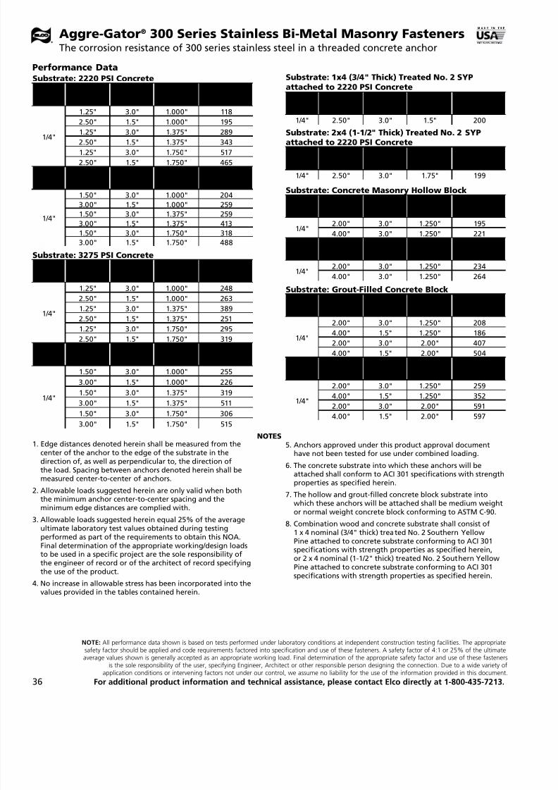
7/17/2019 Elco 2014 Catalog
http://slidepdf.com/reader/full/elco-2014-catalog 36/44
NOTE: All performance data shown is based on tests performed under laboratory conditions at independent construction testing facilities. The appropriatesafety factor should be applied and code requirements factored into specification and use of these fasteners. A safety factor of 4:1 or 25% of the ultimateaverage values shown is generally accepted as an appropriate working load. Final determination of the appropriate safety factor and use of these fasteners
is the sole responsibility of the user, specifying Engineer, Architect or other responsible person designing the connection. Due to a wide variety ofapplication conditions or intervening factors not under our control, we assume no liability for the use of the information provided in this document.
For additional product information and technical assistance, please contact Elco directly at 1-800-435-7213.36
Substrate: 2220 PSI Concrete
AnchorDia.
Min.Edge Dist.
Min.Spacing
Min.Embed.
AllowableTension (lbs)
1/4"
1.25" 3.0" 1.000" 118
2.50" 1.5" 1.000" 195
1.25" 3.0" 1.375" 289
2.50" 1.5" 1.375" 343
1.25" 3.0" 1.750" 517
2.50" 1.5" 1.750" 465
AnchorDia.
Min.Edge Dist.
Min.Spacing
Min.Embed.
AllowableShear (lbs)
1/4"
1.50" 3.0" 1.000" 204
3.00" 1.5" 1.000" 259
1.50" 3.0" 1.375" 259
3.00" 1.5" 1.375" 413
1.50" 3.0" 1.750" 318
3.00" 1.5" 1.750" 488
Substrate: 3275 PSI Concrete
Anchor
Dia.
Min.
Edge Dist.
Min.
Spacing
Min.
Embed.
Allowable
Tension (lbs)
1/4"
1.25" 3.0" 1.000" 248
2.50" 1.5" 1.000" 263
1.25" 3.0" 1.375" 389
2.50" 1.5" 1.375" 251
1.25" 3.0" 1.750" 295
2.50" 1.5" 1.750" 319
AnchorDia.
Min. Edge Dist.
Min.Spacing
Min.Embed.
AllowableShear (lbs)
1/4"
1.50" 3.0" 1.000" 255
3.00" 1.5" 1.000" 226
1.50" 3.0" 1.375" 319
3.00" 1.5" 1.375" 511
1.50" 3.0" 1.750" 3063.00" 1.5" 1.750" 515
Substrate: 1x4 (3/4" Thick) Treated No. 2 SYPattached to 2220 PSI Concrete
AnchorDia.
Min.Edge Dist.
Min.Spacing
Min.Embed.
AllowableShear (lbs)
1/4" 2.50" 3.0" 1.5" 200
Substrate: 2x4 (1-1/2" Thick) Treated No. 2 SYPattached to 2220 PSI Concrete
AnchorDia.
Min.Edge Dist.
Min.Spacing
Min.Embed.
AllowableShear (lbs)
1/4" 2.50" 3.0" 1.75" 199
Substrate: Concrete Masonry Hollow Block
AnchorDia.
Min.Edge Dist.
Min.Spacing
Min.Embed.
AllowableTension (lbs)
1/4"2.00" 3.0" 1.250" 195
4.00" 3.0" 1.250" 221
AnchorDia.
Min.Edge Dist.
Min.Spacing
Min.Embed.
AllowableShear (lbs)
1/4"
2.00" 3.0" 1.250" 234
4.00" 3.0" 1.250" 264
Substrate: Grout-Filled Concrete Block
AnchorDia.
Min.Edge Dist.
Min.Spacing
Min.Embed.
AllowableTension (lbs)
1/4"
2.00" 3.0" 1.250" 208
4.00" 1.5" 1.250" 186
2.00" 3.0" 2.00" 407
4.00" 1.5" 2.00" 504
AnchorDia.
Min.Edge Dist.
Min.Spacing
Min.Embed.
AllowableShear (lbs)
1/4"
2.00" 3.0" 1.250" 259
4.00" 1.5" 1.250" 352
2.00" 3.0" 2.00" 591
4.00" 1.5" 2.00" 597
NOTES1. Edge distances denoted herein shall be measured from the
center of the anchor to the edge of the substrate in thedirection of, as well as perpendicular to, the direction ofthe load. Spacing between anchors denoted herein shall bemeasured center-to-center of anchors.
2. Allowable loads suggested herein are only valid when boththe minimum anchor center-to-center spacing and theminimum edge distances are complied with.
3. Allowable loads suggested herein equal 25% of the averageultimate laboratory test values obtained during testingperformed as part of the requirements to obtain this NOA.Final determination of the appropriate working/design loadsto be used in a specific project are the sole responsibility ofthe engineer of record or of the architect of record specifyingthe use of the product.
4. No increase in allowable stress has been incorporated into thevalues provided in the tables contained herein.
5. Anchors approved under this product approval documenthave not been tested for use under combined loading.
6. The concrete substrate into which these anchors will beattached shall conform to ACI 301 specifications with strengthproperties as specified herein.
7. The hollow and grout-filled concrete block substrate intowhich these anchors will be attached shall be medium weightor normal weight concrete block conforming to ASTM C-90.
8. Combination wood and concrete substrate shall consist of1 x 4 nominal (3/4" thick) treated No. 2 Southern YellowPine attached to concrete substrate conforming to ACI 301
specifications with strength properties as specified herein,or 2 x 4 nominal (1-1/2" thick) treated No. 2 Southern YellowPine attached to concrete substrate conforming to ACI 301specifications with strength properties as specified herein.
Performance Data
Aggre-Gator® 300 Series Stainless Bi-Metal Masonry FastenersThe corrosion resistance of 300 series stainless steel in a threaded concrete anchor
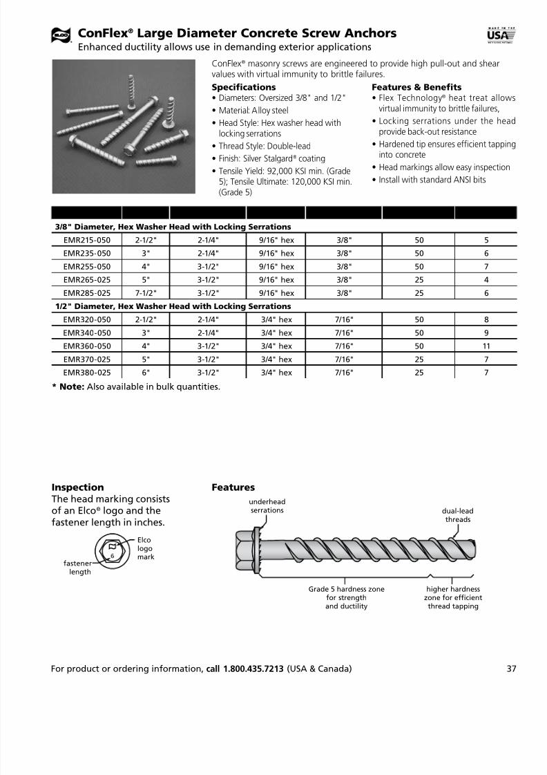
7/17/2019 Elco 2014 Catalog
http://slidepdf.com/reader/full/elco-2014-catalog 37/44
3For product or ordering information, call 1.800.435.7213 (USA & Canada)
ConFlex® Large Diameter Concrete Screw AnchorsEnhanced ductility allows use in demanding exterior applications
Features & Benefits• Flex Technology® heat treat allow
virtual immunity to brittle failures,
• Locking serrations under the hea
provide back-out resistance• Hardened tip ensures efficient tappin
into concrete
• Head markings allow easy inspection
• Install with standard ANSI bits
Specifications• Diameters: Oversized 3/8" and 1/2"
• Material: Alloy steel
• Head Style: Hex washer head with
locking serrations• Thread Style: Double-lead
• Finish: Silver Stalgard® coating
• Tensile Yield: 92,000 KSI min. (Grade5); Tensile Ultimate: 120,000 KSI min.(Grade 5)
ConFlex® masonry screws are engineered to provide high pull-out and shearvalues with virtual immunity to brittle failures.
Catalog No. Length Thread Length Drive Size Drill Bit Size Box Quantity* Box Weight
3/8" Diameter, Hex Washer Head with Locking Serrations
EMR215-050 2-1/2" 2-1/4" 9/16" hex 3/8" 50 5
EMR235-050 3" 2-1/4" 9/16" hex 3/8" 50 6
EMR255-050 4" 3-1/2" 9/16" hex 3/8" 50 7EMR265-025 5" 3-1/2" 9/16" hex 3/8" 25 4
EMR285-025 7-1/2" 3-1/2" 9/16" hex 3/8" 25 6
1/2" Diameter, Hex Washer Head with Locking Serrations
EMR320-050 2-1/2" 2-1/4" 3/4" hex 7/16" 50 8
EMR340-050 3" 2-1/4" 3/4" hex 7/16" 50 9
EMR360-050 4" 3-1/2" 3/4" hex 7/16" 50 11
EMR370-025 5" 3-1/2" 3/4" hex 7/16" 25 7
EMR380-025 6" 3-1/2" 3/4" hex 7/16" 25 7
Elcologomark
fastenerlength
InspectionThe head marking consistsof an Elco® logo and thefastener length in inches.
Features
underheadserrations dual-lead
threads
Grade 5 hardness zonefor strengthand ductility
higher hardnesszone for efficientthread tapping
* Note: Also available in bulk quantities.

7/17/2019 Elco 2014 Catalog
http://slidepdf.com/reader/full/elco-2014-catalog 38/44
NOTE: All performance data shown is based on tests performed under laboratory conditions at independent construction testing facilities. The appropriatesafety factor should be applied and code requirements factored into specification and use of these fasteners. A safety factor of 4:1 or 25% of the ultimateaverage values shown is generally accepted as an appropriate working load. Final determination of the appropriate safety factor and use of these fasteners
is the sole responsibility of the user, specifying Engineer, Architect or other responsible person designing the connection. Due to a wide variety ofapplication conditions or intervening factors not under our control, we assume no liability for the use of the information provided in this document.
For additional product information and technical assistance, please contact Elco directly at 1-800-435-7213.38
ConFlex® Large Diameter Concrete Screw AnchorsTechnical Information
1,819 PSI
Dia . Edge Distance Embedment Pull-out Shear
3/8"
1-7/8"(5d)
1-1/2" 1,364 x
2" 2,995 x
2-1/2" 3,226 1,534
3-1/2" 5,379 2,170
2-5/8"
1-1/2" x x
2" x x
2-1/2" 3,620 2,459
3-1/2" 6,070 3,902
3-3/4"(10d)
1-1/2" 1,232 4,766
2" 3,296 5,658
2-1/2" 3,936 6,419
3-1/2" 6,493 7,047
1/2"
2
1-3/4" x x
2" x x
3" x x
4" x x
2-1/2"(5d)
1-3/4" 2,266 x2" 2,706 x
3" 4,666 4,549
4" 7,058 6,960
3-1/2"
1-3/4" x x
2" x x
3" 5,483 5,739
4" 8,656 8,028
4"
1-3/4" x x
2" x x
3" x x
4" x x
5"(10d)
1-3/4" 2,090 6,081
2" 2,875 7,167
3" 6,042 9,148
4" 8,732 9,631
4,510 PSI
Dia. Edge Distance Embedment Pull-out Shear
3/8"
1-7/8"(5d)
1-1/2" 2,497 x
2" 3,169 x
2-1/2" 5,063 2,111
3-1/2" 9,288 2,732
2-5/8"
1-1/2"
2"
2-1/2" 5,111 2,667
3-1/2" 8,438 4,046
3-1/2"
1-1/2" 2,055 x
2" x 5,810
2-1/2" 4,778 x
3-1/2" x x
3-3/4"(10d)
1-1/2" 2,055 3,414
2" x 5,810
2-1/2" 5,111 7,309
3-1/2" 9,508 8,339
1/2"
2"
1-3/4" 3,515 x2" 4,388 x
3" 6,719 2,229
4" 11,076 3,860
3"(6d)
1-3/4" x x
2" x x
3" x x
4" x x
3-1/2"
1-3/4" x x
2" x x
3" 7,646 x
4" 10,234 x
4"
1-3/4" 2,887 6,787
2" 4,310 6,678
3" 8,169 8,489
4" 11,111 10,942
5"(10d)
1-3/4" x x
2" x x
3" x x
4" x x
ConFlex® Performance Data†
Ultimate Value (Lbs) in Concrete
† NOTE: Indicated pull-out and shear values listed are ultimatevalues and were obtained in tests conducted by HETI/ Miami,FL, an independent test lab. These figures are offered only as aguide and are not guaranteed in any way by Elco ConstructionProducts. A safety factor of 4:1 or 25% of ultimate values aregenerally accepted as a safe working load.
Testing was done per ASTM E 488 - 96. Additional technicalinformation is available upon request.
Dimensional Properties
3/8" Diameter 1/2" Diameter
Drive system: 9/16" hex Drive system: 3/4" hex
Washer diameter: 11/16" Washer diameter: 1.0"
Thread O.D.: .430" Thread O.D.: .525"
Thread root: .345" Thread root: .405"
Unthreaded shank dia.: .360" Unthreaded shank dia.: .426"
Head mark: Elco logo markand length in inches
Head mark: Elco logo markand length in inches
Recommended min. embedment, all diameters: 2"
Installation of 3/8" Con-Flex Screw Anchors:• Standard 3/8" ANSI masonry drill bit (.398" +.000"/-.010")
• Recommended functional masonrydrill bit length: minimum 1" more than fastener length
Installation of 1/2" Con-Flex Screw Anchors:• Standard 7/16" ANSI masonry drill bit (.468" +.000"/-.010")
• Recommended functional masonrydrill bit length: minimum 1" more than fastener length

7/17/2019 Elco 2014 Catalog
http://slidepdf.com/reader/full/elco-2014-catalog 39/44
3For product or ordering information, call 1.800.435.7213 (USA & Canada)
CatalogNo. Description
RodSize
SteelThickness
Qty. perShipper*
Wt. PerShipper
UL PipeSize
UL SteelThickness
FM PipeSize
FM SteelThickness
For Steel Applications
Vertical Mount – End-Drilled Head
EZG160 1/4-20 x 1 #3 point 1/4/20 .060 – .250 300 17 N/A N/A N/A N/A
EZG450 1/4-20 x 1 #2 point 3/8/16 .060 – .125 300 15 4" 0.125"EZG470 1/4-20 x 1 #3 point 3/8/16 .060 – .250 300 17 4" 0.125" 4" 12 ga.
EZG471 1/4-20 x 1 #3 point w/nuts 3/8/16 .060 – .250 300 15 4" 0.060" 4" 16 ga.
EZG490 1/4-20 x 1-1/2 #3 point 3/8/16 .060 – .250 300 17 4" 0.125" 4" 12 ga.
EZG491 1/4-20 x 1-1/2 #3 point w/nuts 3/8/16 .060 – .250 300 17 4" 0.060" 4" 16 ga.
EZG530 1/4-20 x 2 #3 point 3/8/16 .060 – .250 300 18 4" 0.125"
EZG540 1/4-20 x 3 #3 point 3/8/16 .060 – .250 300 21
EZG510 1/4-20 x 1-1/2 #5 point 3/8/16 .187 – .500 300 17 4" 0.125" 4" 0.125"
EZG511 1/4-20 x 1-1/2 #5 point w/nuts 3/8/16 .060 – .500 300 30 4" 0.060" 4" 16 ga.
EZG610 1/4-20 collapsing insert 1/4/20 26 ga. –.187" 150 4 N/A N/A N/A N/A
EZG580 1/4-20 x 1; use with EZG610 3/8/16 26 ga. –.187" 150 7 2.5" 22 ga. 4" 12 ga.
EZG590 1/4-20 x 1; use with EZG610 3/8/16 26 ga. –.187" 150 7 3.5" 18 ga. 4" 12 ga.EZG600 1/4-20 x 1; use with EZG610 3/8/16 26 ga. –.187" 150 7 4" 16 ga. 4" 12 ga.
Horizontal Mount – Cross-Drilled Head
EZH155 1/4-20 x 1 #3 point 1/4/20 .060 – .250 300 17 N/A N/A N/A N/A
EZH455 1/4-20 x 1 #2 point 3/8/16 .060 – .125 300 15
EZH475 1/4-20 x 1 #3 point 3/8/16 .060 – .250 300 15
EZH476 1/4-20 x 1 #3 point w/nuts 3/8/16 .060 – .250 300 16 4" 0.060" 4" 16 ga.
EZH495 1/4-20 x 1-1/2 #3 point 3/8/16 .060 – .250 300 16
EZH496 1/4-20 x 1-1/2 #3 point w/nuts 3/8/16 .060 – .250 300 17 4" 0.060" 4" 16 ga.
EZH515 1/4-20 x 1-1/2 #5 point 3/8/16 .187 – .500 300 16
EZH516 1/4-20 x 1-1/2 #5 point w/nuts 3/8/16 .060 – .500 300 18 4" 0.060" 4" 16 ga.
EZH535 1/4-20 x 2 #3 point 3/8/16 .060 – .250 300 16
HangerMate® anchors accept 1/4-20, 3/8-16 or 1/2" threaded rod andcomponents of piping systems for attachment to steel, masonry, and wood.
Specifications• Sizes: For use with 1/4-20 and
3/8-16 threaded rod; adaptor installs1/2" threaded rod
•
Lengths: 1-1/8" to 3"• Drive System: Hex
• Material: Carbon steel
• Finish: Plating per ASTM B633Type II Class 12
Features & Benefits• Eases installation of sprinkler systems
strut, HVAC, cable trays and variouspiping systems
•
Self-drilling points for steel; in woodapplications, no pre-drilling is require
• Many styles UL listed and/orFM approved
• Installs with one universalHangerMate drive socket
HangerMate® Threaded Rod Anchoring SystemAnchoring system for threaded rod components

7/17/2019 Elco 2014 Catalog
http://slidepdf.com/reader/full/elco-2014-catalog 40/44
40 For product or ordering information, call 1.800.435.7213 (USA & Canada)
CatalogNo. Description
RodSize
QuantityPer Shipper*
Weight PerShipper
ULPipe Size
FMPipe Size
For Steel, Wood or Concrete
Vertical Mount – End-Drilled Head
EZG910 1/4-10X2 1/4/20 300 20 NA NA
EZG930 1/4-10X2 3/8/16 300 20
Horizontal Mount – Cross-Drilled HeadEZH935 1/4-10X2 3/8/16 300 20 NA NA
Catalog No. Description Rod SizeQuantity Per
Shipper*Weight Per
Shipper UL Pipe Size FM Pipe Size
For Wood Applications
Vertical Mount – End-Drilled Head
EZG315 5/16 x 2-1/4 1/4/20 300 22 NA NA
EZG650 5/16 x 2-1/4 3/8/16 300 22 4" 4"
EZG670 5/16 x 3 3/8/16 300 23 4" 4"Horizontal Mount – Cross-Drilled Head
EZH320 5/16 x 2-1/4 1/4/20 300 22 NA NA
EZH665 5/16 x 2-1/4 3/8/16 300 22 3-1/2
For Concrete Applications
Vertical Mount – End-Drilled Head
EZG365 5/16 x 2-1/4 1/4/20 300 22 NA NA
EZG730 5/16 x 2-1/4 3/8/16 300 22 4"
Horizontal Mount – Cross-Drilled Head
EZH370 5/16 x 2-1/4 1/4/20 300 22 NA NA
EZH735 5/16 x 2-1/4 3/8/16 300 22 4"
All Materials – Adapter for Hanging 1/2" Rod†
EZE270 1/2/13 150 25 NA NA† Simply install any 3/8" HangerMate anchor as required, then thread EZE270 adapter into it.
HangerMate MP (Multi-Purpose) AnchorsWorks in all three substrates
HangerMate Installation Tools
Catalog No. Description Quantity
EZE215 Drive Socket (for steel and wood applications) 1
EZE220 Drive Sleeve (for concrete applications) 1
EZE240 Drill Bit Adapter Kit 1
EZE320 Collared 25/64 Drill Bit for installing HangerMate LG anchors 1EZE340 ANSI 1/4" Tanged Drill Bit for Hammer Drills 1
EZE350 ANSI 1/4" SDS Drill Bit for Rotary Hammer Drills 1
EZE360 7/32" Tanged Drill Bit for Hammer Drills installing HangerMate MP anchors 1
EZE380 7/32" SDS Drill Bit for Rotary Hammer Drills installing HangerMate MP anchors 1
EZE290 Setting Tool for EZG580/EZG590/EZG600/EZG610 components 1
HangerMate® Threaded Rod Anchoring SystemAnchoring system for threaded rod components

7/17/2019 Elco 2014 Catalog
http://slidepdf.com/reader/full/elco-2014-catalog 41/44
NOTE: All performance data shown is based on tests performed under laboratory conditions at independent construction testing facilities. The appropriatesafety factor should be applied and code requirements factored into specification and use of these fasteners. A safety factor of 4:1 or 25% of the ultimateaverage values shown is generally accepted as an appropriate working load. Final determination of the appropriate safety factor and use of these fastenersis the sole responsibility of the user, specifying Engineer, Architect or other responsible person designing the connection. Due to a wide variety ofapplication conditions or intervening factors not under our control, we assume no liability for the use of the information provided in this document.
For additional product information and technical assistance, please contact Elco directly at 1-800-435-7213. 4
HangerMate® Threaded Rod Anchoring SystemAnchoring system for threaded rod components
Steel Applications
Vertical Mount – End-Drilled Head
Rod Size Cat. No. Description UL Pipe Size UL Steel Thickness FM Pipe Size FM Steel Thicknes
3/8-16 EZG450 1/4-20X1 #2 point 4" 0.125"3/8-16 EZG470 1/4-20X1 #3 point 4" 0.125" 4" 12 ga.
3/8-16 EZG471 1/4-20X1 #3 point w/nuts 4" 0.060" 4" 16 ga.
3/8-16 EZG490 1/4-20X1-1/2 #3 point 4" 0.125" 4" 12 ga.
3/8-16 EZG491 1/4-20X1-1/2 #3 point w/nuts 4" 0.060" 4" 16 ga.
3/8-16 EZG530 1/4-20X2 #3 point – – 4" 0.125"
3/8-16 EZG510 1/4-20X1-1/2 #5 point 4" 0.125" 4" 0.125"
3/8-16 EZG511 1/4-20X1-1/2 #5 point w/nuts 4" 0.060" 4" 16 ga.
1/4-20 EZG610 1/4-20 collapsing insert N/A N/A N/A N/A
3/8-16 EZG580 1/4-20X1; use with EZG610 2.5" 22 ga. 4" 12 ga.
3/8-16 EZG590 1/4-20X1; use with EZG610 3.5" 18 ga. 4" 12 ga.
3/8-16 EZG600 1/4-20X1; use with EZG610 4" 16 ga. 4" 12 ga.
Horizontal Mount – Cross-Drilled HeadRod Size Cat. No. Description UL Pipe Size UL Steel Thickness FM Pipe Size FM Steel Thicknes
3/8-16 EZH476 1/4-20X1 #3 point w/nuts 4" 0.060" 4" 16 ga.
3/8-16 EZH496 1/4-20X1-1/2 #3 point w/nuts 4" 0.060" 4" 16 ga.
3/8-16 EZH516 1/4-20X1-1/2 #5 point w/nuts 4" 0.060" 4" 16 ga.
UL Listings and FM Approvals
Wood Applications
Vertical Mount – End-Drilled Head
Rod Size Elco Cat. No. Description UL Pipe Size FM Pipe Size
3/8-16 EZG650 5/16X2-1/4 4" 4"
3/8-16 EZG670 5/16X3 4" 4"
Horizontal Mount – Cross-Drilled Head
Rod Size Elco Cat. No. Description UL Pipe Size FM Pipe Size3/8-16 EZH665 5/16X2-1/4 3-1/2" —
Concrete Applications
Vertical Mount – End-Drilled Head
Rod Size Elco Cat. No. Description UL Pipe Size FM Pipe Size
3/8-16 EZG730 5/16X2-1/4 — 4"
Horizontal Mount – Cross-Drilled Head
Rod Size Elco Cat. No. Description UL Pipe Size FM Pipe Size
3/8-16 EZH735 5/16X2-1/4 — 4"
UL Report No. VFXT7.EX4649FM Report No. 3017474, 3049089

7/17/2019 Elco 2014 Catalog
http://slidepdf.com/reader/full/elco-2014-catalog 42/44
42 For product or ordering information, call 1.800.435.7213 (USA & Canada)
RapidSet® ToolsThe fastest, easiest and most reliable way to install machine screw anchors
Features & Benefits• Power tool does all the work – no
pounding with setting tools
• Automatically sets anchor just below
the surface• Maximizes expansion of bottom
portion of lead sleeve, which resultsin consistently high pull-out values
Specifications• For machine screw anchor sizes #10,
1/4" and 3/8"
• Designed for use with power tools,
including battery impact drivers• MAXX model allows placement of
1/4" anchors at various depths(up to 2") below the surface
Efficient RapidSet® tools eliminate clumsy hammer and setting processes orexpensive, slow expander tools.*
Catalog No. For Insert-Anchor Size
Standard RapidSet tool
EZB790 #10-24
EZB800 1/4-20
EZB820 3/8-16RapidSet MAXX tool
EZB810 1/4-20
Catalog No. Description
Repair Kits
EZB811 Repair Kit for EZB810 (Rapidset MAXX Tool)
EZB801 Repair Kit for EZB800 (Rapidset Tool for 1/4-20 Inserts)
* Note: RapidSet tools draw the anchor’s internal insert up into the anchor’s outer sleeve; this installation processeliminates the need to maintain a back bearing surface (required by hammer setting tools).

7/17/2019 Elco 2014 Catalog
http://slidepdf.com/reader/full/elco-2014-catalog 43/44

7/17/2019 Elco 2014 Catalog
http://slidepdf.com/reader/full/elco-2014-catalog 44/44
Elco Construction Products701 E. Joppa Road • Towson MD 21286
Phone: 800-435-7213 (USA & Canada)Fax: 563-387-3540
www.elcoconstruction.com
Proud
Member of:
Warranty and Limitation of Liability:All warranties of the Elco® products, expressed
or implied, including the warranties ofmerchantability and fitness for particular purposes
are specifically excluded for the following: Elcowill repair any product which, within twelve
months after sales by Elco Construction Productsor its distributors, is found by Elco to be defective
in material or workmanship – normal wear andtear excepted. This is the sole warranty of Elco
Construction Products and the sole remedyavailable to distributor or buyer. Elco shall notbe liable for any injury, loss of damage, direct,
incidental or consequential, arising from use of, orthe inability to use, any Elco product.
Elco Construction Products has strived for totalaccuracy throughout this catalog. However,
Elco Construction Products shall not be liableor responsible for any typographical errors or
changes in product offering that may occur. If any
questions arise as to the accuracy of this catalog,please contact us at 1-800-435-7213.
Related Documents