Elastic–plastic discontinuous deformation analysis using Mohr–Coulomb model R. G. Mikola* 1 , K. Hatami 2 and D. Doolin 3 The original (i.e. first order) discontinuous deformation analysis (DDA) formulation has two main shortcomings. First, a linear function is used to represent the displacement field in the blocks. This formulation implies that the state of stress (and strain) within each block is constant. Second, the material within each block is assumed as linear elastic. These two major limitations can often render the original DDA analysis method unrealistic and significantly inaccurate. In the modified DDA approach introduced in this study, these two limitations have been addressed. The authors have used the finite element method (FEM) to discretise each block in the DDA formulation using an automatic mesh generation algorithm to determine the distributions of stress and strain within each block to a desired accuracy. In addition, the Mohr–Coulomb elastic–plastic yield criterion is incorporated within the modified DDA analysis method using a time marching algorithm to account for the possibility of material failure. This allows the plastic behaviour (i.e. yielding) of the material within each block be included in the analysis, which is a significant improvement over the original DDA method. The numerical implementation of the Mohr–Coulomb criterion involves trials using initial elastic stress increment and comparisons with the yield criterion within each element. The proposed DDA formulation including the Mohr–Coulomb failure criterion (termed here as the MC-DDA method) is validated against selected analytical solutions, numerical solutions from FLAC verification problems and field measurements. Keywords: DDA, Discontinuous analysis, FEM, Mohr–Coulomb, Jointed rock, Elastic–plastic modelling Introduction The mechanical response of geomaterials such as soft rock and stiff soils that contain joints and faults is characterised by deformations involving both the material elastic–plastic behaviour and slippage along the existing discontinuities. Therefore, realistic simula- tion of these materials subjected to given loading conditions requires that both deformation categories be included in the analysis. The finite element method of analysis is an established approach that can be used to predict the elastic–plastic response of continuous media (e.g. soft soils) with a desirable level of accuracy. In discontinuous elastic media such as jointed hard rock, discrete element methods such as distinct element method (Cundall, 1971, 1987) and discontinuous defor- mation analysis (DDA) (Shi, 1988, 1993) provide accurate and well understood tools to calculate defor- mations along pre-existing discontinuities. One applica- tion of the DDA method is to evaluate the behaviour of jointed rock masses during underground tunnelling/ construction. The stability of tunnel opening has been the subject of several studies during the past two decades (e.g. Akky et al., 1994; Yeung and Leong, 1997; Kim et al., 1994; Hsiung and Shi, 2001; Tsesarsky and Hatzor, 2006). In all these studies involving numerical simulation, the rock masses were assumed as linear elastic blocks with constant stresses and strains. An important limitation of conventional discrete element methods such as DDA is that these formula- tions require that the blocks are either rigid or their deformations involve small strains that are constant throughout each block. In order to address this limitation, several methods have been proposed to extend the basic DDA formulation to problems invol- ving non-uniform deformation. These methods include those in which the Cosserat based DDA formulation is extended using higher order displacement functions (Ma et al., 1996; Koo and Chern, 1996; Hsiung, 2001), approaches in which the finite element methodology is implemented within each discrete element (Jing, 1998) and those where the internal subblocks within each large block are interconnected through stiff springs along their common boundaries so as to maintain the integrity of each block (Lin et al., 1996; Cheng and Zhang, 2000). Mixed finite element/discrete element methods (FEM/ DEM) have also been used to simulate non-uniform 1 Civil Engineering and Environmental Engineering (CEE), University of California, 437 Davis Hall, Berkeley, CA 94720-1710, USA 2 School of Civil Engineering and Environmental Science (CEES), University of Oklahoma, 202 West Boyd St., Room 334, Norman, OK 73019, USA 3 Inventium Systems, 6016 B Avila St., El Cerrito, CA 94530, USA *Corresponding author, email [email protected] 148 ß 2011 Institute of Materials, Minerals and Mining Published by Maney on behalf of the Institute and The AusIMM This article was written and prepared by an officer and/or employee of the U.S. Government as part of their official duties and is not copyrightable Received 11 January 2009; accepted 3 April 2011 DOI 10.1179/1743286311Y.0000000006 Mining Technology 2011 VOL 120 NO 3

Welcome message from author
This document is posted to help you gain knowledge. Please leave a comment to let me know what you think about it! Share it to your friends and learn new things together.
Transcript
Elastic–plastic discontinuous deformationanalysis using Mohr–Coulomb model
R. G. Mikola*1, K. Hatami2 and D. Doolin3
The original (i.e. first order) discontinuous deformation analysis (DDA) formulation has two main
shortcomings. First, a linear function is used to represent the displacement field in the blocks. This
formulation implies that the state of stress (and strain) within each block is constant. Second, the
material within each block is assumed as linear elastic. These two major limitations can often
render the original DDA analysis method unrealistic and significantly inaccurate. In the modified
DDA approach introduced in this study, these two limitations have been addressed. The authors
have used the finite element method (FEM) to discretise each block in the DDA formulation using
an automatic mesh generation algorithm to determine the distributions of stress and strain within
each block to a desired accuracy. In addition, the Mohr–Coulomb elastic–plastic yield criterion is
incorporated within the modified DDA analysis method using a time marching algorithm to
account for the possibility of material failure. This allows the plastic behaviour (i.e. yielding) of the
material within each block be included in the analysis, which is a significant improvement over the
original DDA method. The numerical implementation of the Mohr–Coulomb criterion involves trials
using initial elastic stress increment and comparisons with the yield criterion within each element.
The proposed DDA formulation including the Mohr–Coulomb failure criterion (termed here as the
MC-DDA method) is validated against selected analytical solutions, numerical solutions from
FLAC verification problems and field measurements.
Keywords: DDA, Discontinuous analysis, FEM, Mohr–Coulomb, Jointed rock, Elastic–plastic modelling
IntroductionThe mechanical response of geomaterials such as softrock and stiff soils that contain joints and faults ischaracterised by deformations involving both thematerial elastic–plastic behaviour and slippage alongthe existing discontinuities. Therefore, realistic simula-tion of these materials subjected to given loadingconditions requires that both deformation categoriesbe included in the analysis. The finite element method ofanalysis is an established approach that can be used topredict the elastic–plastic response of continuous media(e.g. soft soils) with a desirable level of accuracy. Indiscontinuous elastic media such as jointed hard rock,discrete element methods such as distinct elementmethod (Cundall, 1971, 1987) and discontinuous defor-mation analysis (DDA) (Shi, 1988, 1993) provideaccurate and well understood tools to calculate defor-mations along pre-existing discontinuities. One applica-tion of the DDA method is to evaluate the behaviour of
jointed rock masses during underground tunnelling/construction. The stability of tunnel opening has beenthe subject of several studies during the past two decades(e.g. Akky et al., 1994; Yeung and Leong, 1997; Kimet al., 1994; Hsiung and Shi, 2001; Tsesarsky andHatzor, 2006). In all these studies involving numericalsimulation, the rock masses were assumed as linearelastic blocks with constant stresses and strains.
An important limitation of conventional discreteelement methods such as DDA is that these formula-tions require that the blocks are either rigid or theirdeformations involve small strains that are constantthroughout each block. In order to address thislimitation, several methods have been proposed toextend the basic DDA formulation to problems invol-ving non-uniform deformation. These methods includethose in which the Cosserat based DDA formulation isextended using higher order displacement functions (Maet al., 1996; Koo and Chern, 1996; Hsiung, 2001),approaches in which the finite element methodology isimplemented within each discrete element (Jing, 1998)and those where the internal subblocks within each largeblock are interconnected through stiff springs alongtheir common boundaries so as to maintain the integrityof each block (Lin et al., 1996; Cheng and Zhang, 2000).
Mixed finite element/discrete element methods (FEM/DEM) have also been used to simulate non-uniform
1Civil Engineering and Environmental Engineering (CEE), University ofCalifornia, 437 Davis Hall, Berkeley, CA 94720-1710, USA2School of Civil Engineering and Environmental Science (CEES),University of Oklahoma, 202 West Boyd St., Room 334, Norman, OK73019, USA3Inventium Systems, 6016 B Avila St., El Cerrito, CA 94530, USA
*Corresponding author, email [email protected]
148
� 2011 Institute of Materials, Minerals and MiningPublished by Maney on behalf of the Institute and The AusIMMThis article was written and prepared by an officer and/or employee of the U.S. Government as part of their official duties and is not copyrightableReceived 11 January 2009; accepted 3 April 2011DOI 10.1179/1743286311Y.0000000006 Mining Technology 2011 VOL 120 NO 3
deformation of jointed rocks with the advantage that theirderivation and implementation in the analysis are rela-tively straightforward (Munjiza, 2004). Grayeli andMortazavi (2006) as well as Grayeli and Hatami (2008)present the finite element derivations for the implementa-tion of FEM/DEM in DDA. In this formulation, theblocks are discretised internally using linear elastic,quadratic (i.e. six-noded) triangular elements which aresuitable to simulate blocks of any arbitrary shape. Grayeliand Mortazavi (2006) verified their implementationagainst the Kirsch solution for the displacement fieldaround a circular cavity in an infinite elastic medium. Theirresults indicated that their DDA approach predicted theelastic deformations around the circular cavity withreasonable accuracy.
In this paper, the finite element aspect of a mixed FEM/DDA code is derived and verified for a three-nodedtriangular finite element. The current derivation is animprovement over those of Shyu (1993) and Grayeli andMortazavi (2006) in that it includes the Mohr–Coulombelastic–plastic constitutive model for the blocks asopposed to the linear elastic model adopted in theprevious studies. In addition, the finite element mesh inthe present study is generated using an internal discretisa-tion scheme based on an automatic (i.e. Delaunay type)mesh generation algorithm (Shewchuk, 1997). Themodified DDA formulation described in this paper(termed as the MC-DDA method) is verified against theSalencon’s solution (Salencon, 1969) for displacementsaround a circular cavity in an infinite elastic–plasticmedium. The capabilities and accuracy of the MC-DDAmethod are demonstrated using a case study involvingfield measurements and predictions using FLAC (Itasca,2005) simulations.
Approximation of displacement field inblocksIn the displacement based FEM, the primary unknownquantity is the displacement field, which varies over theproblem domain. In two-dimensional plane strainproblems, the displacement field is characterised bytwo global vectors u and v, representing displacementcomponents in the x and y directions respectively. Theoriginal DDA algorithm lacks the ability to modelcomplex (e.g. non-uniform) block deformations. In this
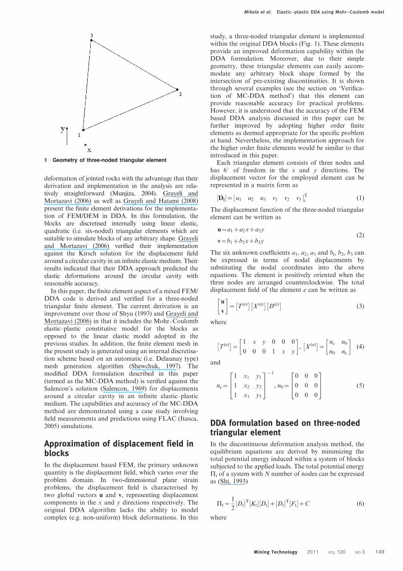
study, a three-noded triangular element is implementedwithin the original DDA blocks (Fig. 1). These elementsprovide an improved deformation capability within theDDA formulation. Moreover, due to their simplegeometry, these triangular elements can easily accom-modate any arbitrary block shape formed by theintersection of pre-existing discontinuities. It is shownthrough several examples (see the section on ‘Verifica-tion of MC-DDA method’) that this element canprovide reasonable accuracy for practical problems.However, it is understood that the accuracy of the FEMbased DDA analysis discussed in this paper can befurther improved by adopting higher order finiteelements as deemed appropriate for the specific problemat hand. Nevertheless, the implementation approach forthe higher order finite elements would be similar to thatintroduced in this paper.
Each triangular element consists of three nodes andhas 6u of freedom in the x and y directions. Thedisplacement vector for the employed element can berepresented in a matrix form as
Di½ �~ u1 u2 u3 v1 v2 v3½ �Ti (1)
The displacement function of the three-noded triangularelement can be written as
u~a1za2xza3y
v~b1zb2xzb3y(2)
The six unknown coefficients a1, a2, a3 and bl, b2, b3 canbe expressed in terms of nodal displacements bysubstituting the nodal coordinates into the aboveequations. The element is positively oriented when thethree nodes are arranged counterclockwise. The totaldisplacement field of the element e can be written as
u
v
� �~ T (e)� �
X (e)� �
D(e)� �
(3)
where
T (e)� �
~1 x y 0 0 0
0 0 0 1 x y
� �, X (e)� �
~nc n0
n0 nc
� �(4)
and
nc~
1 x1 y1
1 x2 y2
1 x3 y3
264
375
{1
, n0~
0 0 0
0 0 0
0 0 0
264
375 (5)
DDA formulation based on three-nodedtriangular elementIn the discontinuous deformation analysis method, theequilibrium equations are derived by minimizing thetotal potential energy induced within a system of blockssubjected to the applied loads. The total potential energyPt of a system with N number of nodes can be expressedas (Shi, 1993)
Pt~1
2Dt½ �T Kt½ � Dt½ �z Dt½ �T Ft½ �zC (6)
where
1 Geometry of three-noded triangular element
Mikola et al. Elastic–plastic DDA using Mohr–Coulomb model
Mining Technology 2011 VOL 120 NO 3 149
Kt½ �~
k11 k12 k13 � � � k1n
k21 k22 k23 � � � k2n
k31 k32 k33 � � � k3n
..
. ... ..
.P
..
.
kn1 kn2 kn3 � � � knn
26666666664
37777777775
,
Dt½ �~
d1
d2
d3
..
.
dn
26666666664
37777777775
, Ft½ �~
f1
f2
f3
..
.
fn
26666666664
37777777775
(7)
In equation (6), C is the energy dissipated by thefrictional force at the interface between the blocks.Elements Kij and Kii in the coefficient matrix inequation (7) are 262 submatrices and elements di andfi are 261 submatrices. By minimising the totalpotential energy function Pt expressed in terms of theforces applied on, and stresses induced in the blocks, theglobal system of equilibrium equations for the assemblyof blocks can be derived in the form
Kt½ � Dt½ �~ Ft½ � (8)
For a system with N nodes, the global stiffness matrix is2N62N in size. In Eq. (6) the off-diagonal contribu-tions to the system matrix will exist only if the blocks arein contact. In other words, the existence of sub-matriceskij and kji is the result of contact between two elementson different but contacting blocks. The followingsections briefly demonstrate the determination ofvarious sub-matrices required to set up the globalequilibrium equation.
Stiffness matrixThe strain energy Pe due to the elastic stresses inelement e can be written as
Pe~1
2
ððef gT sf gdxdy~
1
2D(e)� �T
ððX (e)� �T
B½ �T E(e)� �
B½ � X (e)� �
dxdy D(e)� �
(9)
where, e.g. in a plane strain problem
sf g~ E(e)� �
ef g,
E(e)� �
~E
(1zn)(1{2n)
1{n n 0
n 1{n 0
0 01{2n
2
26664
37775
and B½ �~
Lu
Lx
Lv
Ly
Lu
Lyz
Lv
Lx
266666664
377777775
(10)
Hence, by minimising the energy function Pe, withrespect to the displacement variables, the stiffness term
associated with the elastic stresses can be calculated andadded to the global matrix [Kt] as per below
K(e)i(r)i(s)
h i~ X (e)� �Tðð
B½ �T E(e)� �
B½ �dx dy X (e)� �
r, s~1, 2, 3ð Þ (11)
where i(1), i(2) and i(3) are the numbers of the first,second and third nodes of element respectively. It shouldbe noted that the elements in matrix [B] containxn1 yn2 terms, where n1 and n2 are non-negative integers.As a result, the integrations in equation (11) becomeincreasingly more difficult as the order of the polynomialfunctions in the displacement approximation isincreased. Shi (1993) proposed the 2D and 3D simplexintegration schemes, which allow for the integration ofhigh order polynomials. In this study, the 2D integrationmethod proposed by Shi (1993) is adopted. Othersubmatrices representing initial stresses, inertial forcesand external loading are determined and added into theglobal equation in a similar fashion.
Initial stressesInitial stresses are often sources of energy within ablocky system. Examples of these stresses are accumu-lated in situ ground stresses caused by tectonic move-ments, residual stresses due to manufacture of materialsor misfit of mechanical components, or constructioninduced residual stresses (e.g. due to soil compaction). Inthe DDA method, the stresses are accumulated from theprevious computational step. Therefore, the potentialenergy due to initial stresses can be easily implementedinto the DDA algorithm. In the first order DDAformulation, the state of stress within an element isassumed to be constant. The potential energy corre-sponding to constant initial stresses in an element e canbe written as
Pis~
ððef gT s0� �
dxdy~
D(e)� �Tðð
X (e)� �T
B½ �T E(e)� �
B½ � X (e)� �
dxdy D(e)0
h i (12)
By minimising the above energy function with respect tothe displacement variables, the following force matrixwill be determined, which must be added to the globalforce matrix
F(e)i(r)
h i~{
ððX (e)� �T
B½ �T E(e)� �
B½ � X (e)� �
dxdy D(e)0
h ir~1, 2, 3ð Þ (13)
or:
F(e)i(r)
h i~ X (e)� �T
H½ � X (e)� �
D(e)0
h ir~1, 2, 3ð Þ
where
H½ �~ðð
B½ �T E(e)� �
B½ �dxdy (14)
and i(1), i(2) and i(3) denote the node numbers for thefirst, second and third nodes in element e respectively.
The matrix F(e)i(r)
h icalculated from equations (13) and
(14) is added to the global force matrix.
Mikola et al. Elastic–plastic DDA using Mohr–Coulomb model
150 Mining Technology 2011 VOL 120 NO 3
Inertial forcesThe inertial force per unit area of element e is
Pi~{ML2
Lt2
u(t)
v(t)
� �~{M T (e)
� �X (e)� � L2Dt
Lt2(15)
where M is the mass per unit area, and u(t) and v(t) denotethe x and y components of the time dependent displace-ment at any point (x,y) in element e respectively. Thepotential energy of the inertial force of an element e is
Pi~{M D(e)� �Tðð
X (e)� �T
T (e)� �T
T (e)� �
X (e)� � L2Dt
Lt2dxdy (16)
It can be easily shown that the inertial force matrix is ofthe same form as that in the original DDA. Therefore
K(e)i(r)i(s)
h i~
2M
Dt2X (e)� � ðð
T (e)� �
T (e)� �
dxdy X (e)� �
r, s~1, 2, 3ð Þ(17)
F(e)i(r)
h i~{
2M
DtX (e)� � ðð
T (e)� �
T (e)� �
dxdy X (e)� �
V(e)0
h ir~1, 2, 3ð Þ
where Dt is the duration of a time step, and V(e)0
h iis the
element velocity accumulated from the previous time
step. The integralÐÐ
T (e)� �T
T (e)� �
dxdy in the present study
is calculated using the simplex method outlined by Shi(1996).
Elastic–plastic behaviour of the blocksThe basic principle in analysing the elastic–plasticbehaviour of materials is to decompose the total strainet into two components and express it in incrementalform in terms of elastic (ee) and plastic (ep) strains as
det~deezdep (18)
Hooke’s law is used to relate the stress rates to the elasticstrain rates. Substitution of equation (18) into Hooke’slaw leads to
dse~ Ee½ �dee~ Ee½ � det{dep�
(19)
According to the flow rule theory of plasticity (Lubliner,1991), plastic strain rates are proportional to thederivative of the yield function with respect to thestresses. This means that the plastic strain can berepresented as vectors perpendicular to the yield surface.This classical form of the plasticity theory is referred to asthe associated plasticity. However, the theory of asso-ciated plasticity leads to an overprediction of dilatancyfor Mohr–Coulomb type yield functions (equation (20))
f ~1
2s1{s3ð Þz 1
2s1zs3ð Þ sin w{c cos w (20)
Therefore, in addition to the yield function, a plasticpotential function g is introduced in the formulation usedto describe the plastic behaviour of the material. The caseg5f is denoted as associated plasticity. In general, theplastic strain rates are written in the form
dep~dlLg
Ls(21)
where l is the plastic multiplier and
dl~Lg=Lsð Þ E(e)
� �Lf =Lsð Þ E(e)½ � LgT=Lsð Þ det (22)
Combining equations (19), (21) and (22) leads to thefollowing elastic–plastic formulation for stress (Smithand Griffiths, 1998)
ds~ E½ �epdee (23a)
where
E½ �ep~ Ee½ �{Ee½ � Lg=Lsð Þ Lf T=Ls
� Ee½ �
Lf =Lsð Þ Ee½ � LgT=Lsð Þ (23b)
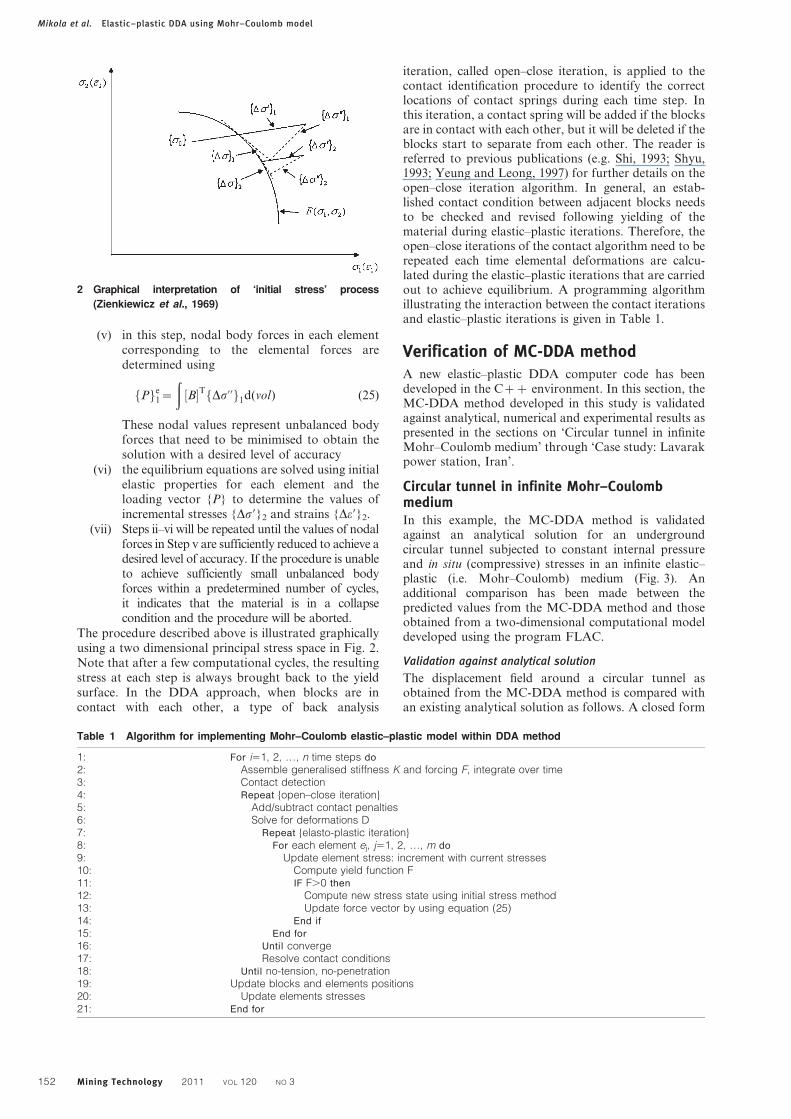
Zienkiewicz et al. (1969) presented an alternativeformulation in which the predicted magnitudes of stressess in each calculation step are corrected for plasticbehaviour. In this approach, termed as the initial stressapproach, the stress magnitudes in each element areinitially calculated using the element elastic stiffnessmatrix. However, stress correction terms are subsequentlyapplied to these stresses to revise their magnitudes tofailure stresses (e.g. the values corresponding to theMohr–Coulomb failure criterion for the material). Thisprocedure has the advantage that it is capable ofsimulating any form of elastic–plastic behaviour (includ-ing elastic–perfectly plastic response) using a simple andstraightforward approach which is amenable to computerprogramming. The computation algorithm to determineincremental stresses in an elastic–plastic material aspresented by Zienkiewicz et al. (1969) involves thefollowing steps:
(i) a prescribed load increment is applied to themodel and the values of incremental elasticstresses {Ds9}1 and strains {De9}1 are calculated
(ii) incremental stresses in each calculation step{Ds9}1 are added to the initial values {s0} toobtain new values {s9}. It is checked whether:F{s9},0. If this condition holds, then onlyelastic strain changes will occur and the processof calculating stresses is aborted. Otherwise, thecalculations proceed to Step iii
(iii) at this stage, F{s9}>0. If F{s0}50 (i.e. theelement is at yield at the start of this incre-mental step), then the values for {Ds}1 arecalculated using equation (23a) with [E]ep com-puted from equation (23b) using stresses {s9}.In addition, the stresses due to body forcesare determined as: {s0}15{s9}12{s}1. Mostupdated states of stress and strain are stored as:{s}5{s9}2{s0}1 and {e}5{e9}2D{e9}1
(iv) if F{s}.0 but F{s0},0, the intermediate stressvalues corresponding to the onset of materialfailure are determined and the incrementalstresses {Ds}1 are calculated from equation (24)
L sf g1~ E½ �epL e’f g1 (24)
using the most updated values of s1 and e9. Thenewly updated stresses and strains in eachelement including those due to the body forcesare then calculated similar to the proceduredescribed in Step iii
Mikola et al. Elastic–plastic DDA using Mohr–Coulomb model
Mining Technology 2011 VOL 120 NO 3 151
(v) in this step, nodal body forces in each elementcorresponding to the elemental forces aredetermined using
Pf ge1~
ðB½ �T Ds’’f g1d(vol) (25)
These nodal values represent unbalanced bodyforces that need to be minimised to obtain thesolution with a desired level of accuracy
(vi) the equilibrium equations are solved using initialelastic properties for each element and theloading vector {P} to determine the values ofincremental stresses {Ds9}2 and strains {De9}2.
(vii) Steps ii–vi will be repeated until the values of nodalforces in Step v are sufficiently reduced to achieve adesired level of accuracy. If the procedure is unableto achieve sufficiently small unbalanced bodyforces within a predetermined number of cycles,it indicates that the material is in a collapsecondition and the procedure will be aborted.
The procedure described above is illustrated graphicallyusing a two dimensional principal stress space in Fig. 2.Note that after a few computational cycles, the resultingstress at each step is always brought back to the yieldsurface. In the DDA approach, when blocks are incontact with each other, a type of back analysis
iteration, called open–close iteration, is applied to thecontact identification procedure to identify the correctlocations of contact springs during each time step. Inthis iteration, a contact spring will be added if the blocksare in contact with each other, but it will be deleted if theblocks start to separate from each other. The reader isreferred to previous publications (e.g. Shi, 1993; Shyu,1993; Yeung and Leong, 1997) for further details on theopen–close iteration algorithm. In general, an estab-lished contact condition between adjacent blocks needsto be checked and revised following yielding of thematerial during elastic–plastic iterations. Therefore, theopen–close iterations of the contact algorithm need to berepeated each time elemental deformations are calcu-lated during the elastic–plastic iterations that are carriedout to achieve equilibrium. A programming algorithmillustrating the interaction between the contact iterationsand elastic–plastic iterations is given in Table 1.
Verification of MC-DDA methodA new elastic–plastic DDA computer code has beendeveloped in the Czz environment. In this section, theMC-DDA method developed in this study is validatedagainst analytical, numerical and experimental results aspresented in the sections on ‘Circular tunnel in infiniteMohr–Coulomb medium’ through ‘Case study: Lavarakpower station, Iran’.
Circular tunnel in infinite Mohr–CoulombmediumIn this example, the MC-DDA method is validatedagainst an analytical solution for an undergroundcircular tunnel subjected to constant internal pressureand in situ (compressive) stresses in an infinite elastic–plastic (i.e. Mohr–Coulomb) medium (Fig. 3). Anadditional comparison has been made between thepredicted values from the MC-DDA method and thoseobtained from a two-dimensional computational modeldeveloped using the program FLAC.
Validation against analytical solution
The displacement field around a circular tunnel asobtained from the MC-DDA method is compared withan existing analytical solution as follows. A closed form
Table 1 Algorithm for implementing Mohr–Coulomb elastic–plastic model within DDA method
1: For i51, 2, …, n time steps do
2: Assemble generalised stiffness K and forcing F, integrate over time3: Contact detection4: Repeat {open–close iteration}5: Add/subtract contact penalties6: Solve for deformations D7: Repeat {elasto-plastic iteration}8: For each element ej, j51, 2, …, m do
9: Update element stress: increment with current stresses10: Compute yield function F11: IF F.0 then
12: Compute new stress state using initial stress method13: Update force vector by using equation (25)14: End if
15: End for
16: Until converge17: Resolve contact conditions18: Until no-tension, no-penetration19: Update blocks and elements positions20: Update elements stresses21: End for
2 Graphical interpretation of ‘initial stress’ process
(Zienkiewicz et al., 1969)
Mikola et al. Elastic–plastic DDA using Mohr–Coulomb model
152 Mining Technology 2011 VOL 120 NO 3
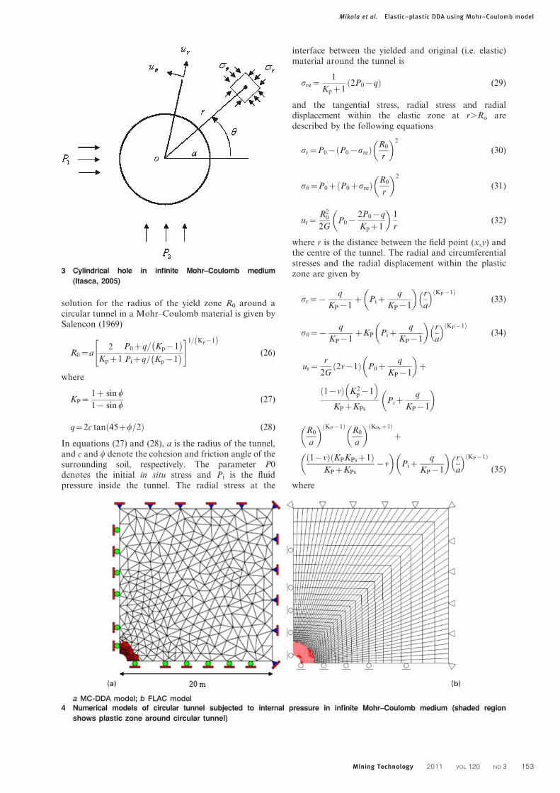
solution for the radius of the yield zone R0 around acircular tunnel in a Mohr–Coulomb material is given bySalencon (1969)
R0~a2
Kpz1
P0zq= Kp{1�
Pizq= Kp{1�
" #1= Kp{1ð Þ(26)
where
KP~1z sin w
1{ sin w(27)
q~2c tan 45zw=2ð Þ (28)
In equations (27) and (28), a is the radius of the tunnel,and c and w denote the cohesion and friction angle of thesurrounding soil, respectively. The parameter P0denotes the initial in situ stress and Pi is the fluidpressure inside the tunnel. The radial stress at the
interface between the yielded and original (i.e. elastic)material around the tunnel is
sre~1
Kpz12P0{qð Þ (29)
and the tangential stress, radial stress and radialdisplacement within the elastic zone at r.Ro aredescribed by the following equations
sr~P0{ P0{sreð Þ R0
r
�2
(30)
sh~P0z P0zsreð Þ R0
r
�2
(31)
ur~R2
0
2GP0{
2P0{q
Kpz1
�1
r(32)
where r is the distance between the field point (x,y) andthe centre of the tunnel. The radial and circumferentialstresses and the radial displacement within the plasticzone are given by
sr~{q
KP{1z Piz
q
KP{1
�r
a
� KP{1ð Þ(33)
sh~{q
KP{1zKP Piz
q
KP{1
�r
a
� KP{1ð Þ(34)
ur~r
2G2n{1ð Þ P0z
q
KP{1
�z
1{nð Þ K2p{1
� KPzKPs
Pizq
KP{1
�
R0
a
� KP{1ð ÞR0
a
� KPsz1ð Þz
1{nð Þ KPKPsz1ð ÞKPzKPs
{n
�Piz
q
KP{1
�r
a
� KP{1ð Þ
(35)
where
a MC-DDA model; b FLAC model4 Numerical models of circular tunnel subjected to internal pressure in infinite Mohr–Coulomb medium (shaded region
shows plastic zone around circular tunnel)
3 Cylindrical hole in infinite Mohr–Coulomb medium
(Itasca, 2005)
Mikola et al. Elastic–plastic DDA using Mohr–Coulomb model
Mining Technology 2011 VOL 120 NO 3 153
KPs~1z sin y
1{ sin y(36)
and parameters y, u and G are the soil dilation angle,Poisson’s ratio and shear modulus respectively.Parameters P1 and P2 are the far field stresses in x andy directions respectively and a is the radius of the tunnel,as defined previously. The following input data havebeen used in the present DDA analysis example:P05P15P2510 MPa, Young’s modulus E55000 MPa,u50?2, a51 m, c50?5 MPa, w530u and y50. Theradius of plastic zone in this example as predicted fromthe closed form solution is Ro52?51 m (equation (26)).The radius of yielded zone calculated by the MC-DDAmethod is Ro52?56 m (Fig. 4a), which is in satisfactoryagreement with the analytical solution.
Validation against FLAC simulation results
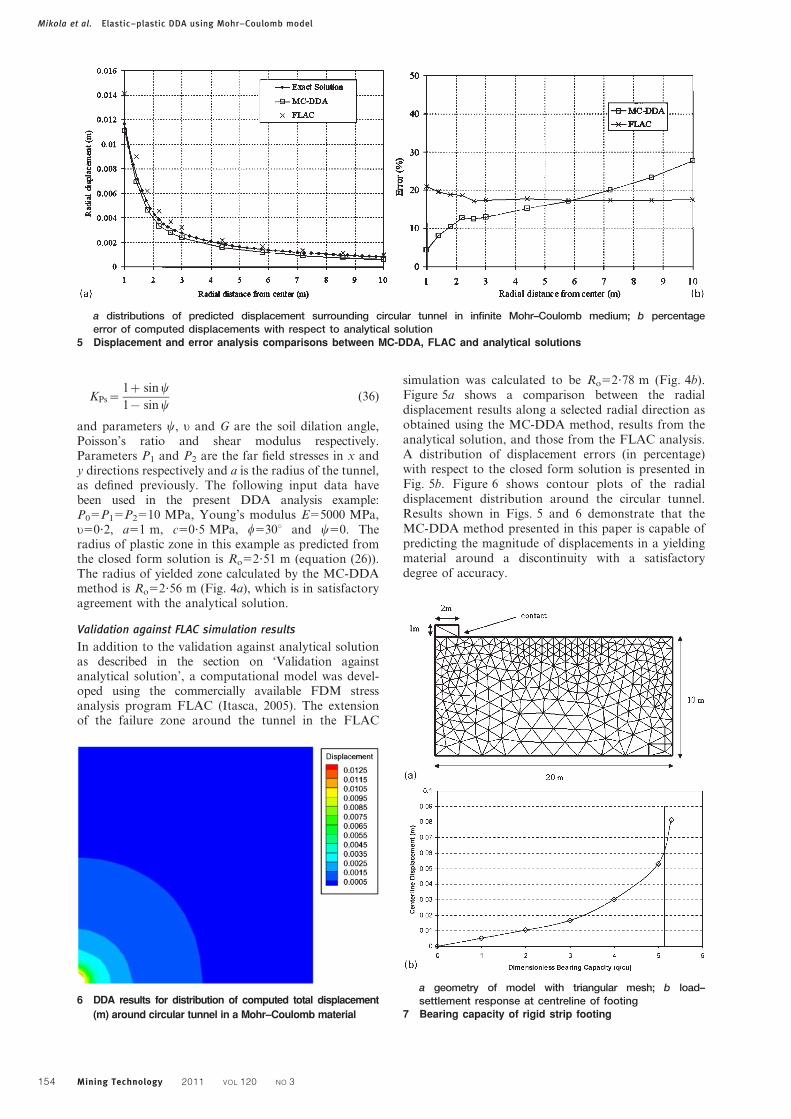
In addition to the validation against analytical solutionas described in the section on ‘Validation againstanalytical solution’, a computational model was devel-oped using the commercially available FDM stressanalysis program FLAC (Itasca, 2005). The extensionof the failure zone around the tunnel in the FLAC
simulation was calculated to be Ro52?78 m (Fig. 4b).Figure 5a shows a comparison between the radialdisplacement results along a selected radial direction asobtained using the MC-DDA method, results from theanalytical solution, and those from the FLAC analysis.A distribution of displacement errors (in percentage)with respect to the closed form solution is presented inFig. 5b. Figure 6 shows contour plots of the radialdisplacement distribution around the circular tunnel.Results shown in Figs. 5 and 6 demonstrate that theMC-DDA method presented in this paper is capable ofpredicting the magnitude of displacements in a yieldingmaterial around a discontinuity with a satisfactorydegree of accuracy.
a distributions of predicted displacement surrounding circular tunnel in infinite Mohr–Coulomb medium; b percentageerror of computed displacements with respect to analytical solution
5 Displacement and error analysis comparisons between MC-DDA, FLAC and analytical solutions
6 DDA results for distribution of computed total displacement
(m) around circular tunnel in a Mohr–Coulomb material
a geometry of model with triangular mesh; b load–settlement response at centreline of footing
7 Bearing capacity of rigid strip footing
Mikola et al. Elastic–plastic DDA using Mohr–Coulomb model
154 Mining Technology 2011 VOL 120 NO 3
Bearing capacity of rigid strip footingIn this example, the accuracy of the elastic–plastic DDAmethod developed in this study (i.e. the MC-DDAmethod) is benchmarked against the theoretical solutionfor the bearing capacity of a rigid strip footing withsmooth surface rested on a purely cohesive soil as givenby the Prandtl’s solution (Smith and Griffiths, 1998).The soil is modelled as a weightless, elastic–perfectlyplastic material governed by the Mohr–Coulomb failurecriterion. The footing width is 4 m. However, due tosymmetry, only one half of the problem is analysed asshown in Fig. 7a. The rigid smooth strip footing hasbeen modelled using a block of 261 m cross-sectionalarea and a unit length out of the analysis plane. In thisbearing capacity analysis, the footing pressure wasgradually increased from zero to an ultimate value thatinduced excessive deformation indicating that thefoundation failed. The magnitude of uniform stressunder the rigid footing was increased by increments of1 kPa in each time step during the loading calculations.The values for the soil Young’s modulus, Poisson’s ratioand shear strength are assumed as: E510 MPa, v50?3and cu5100 kPa respectively. The soil dilation angle
value was assumed to be zero consistent with thePrandtl’s solution. This meant that the soil plasticityincluded a non-associated flow rule with no plasticvolume change. In addition, the interface strengthparameters were set to zero (i.e. c50 and w50). Theplot of the dimensionless bearing capacity factor (q/cu)versus footing displacement at its centreline is shown inFig. 7b. The theoretical value of failure load for thisproblem is given by Prandtl (Smith and Griffiths, 1998)as
qu~Nccu~ pz2ð Þcu
as indicated with a solid line in Fig. 7b. MC-DDAresults in Fig. 7b show that the footing settlementincreases rapidly when the footing pressure approachesthe Prandtl’s value q/cu55?14 indicating that bearingfailure is taking place in the vicinity of the theoreticalfailure load magnitude. Results shown in Fig. 7b arealso comparable to those obtained by Smith andGriffiths in previous verification studies using FEM(Smith and Griffiths, 1998).
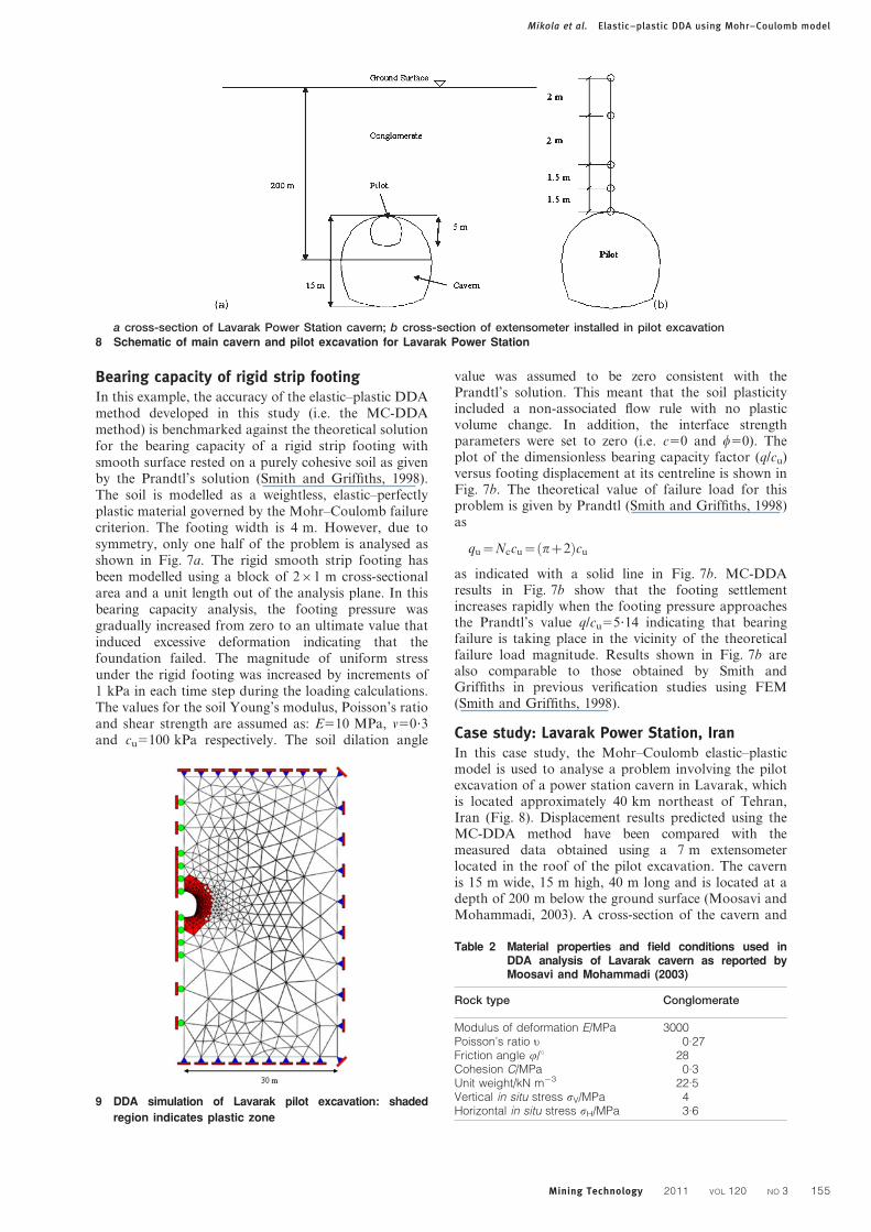
Case study: Lavarak Power Station, IranIn this case study, the Mohr–Coulomb elastic–plasticmodel is used to analyse a problem involving the pilotexcavation of a power station cavern in Lavarak, whichis located approximately 40 km northeast of Tehran,Iran (Fig. 8). Displacement results predicted using theMC-DDA method have been compared with themeasured data obtained using a 7 m extensometerlocated in the roof of the pilot excavation. The cavernis 15 m wide, 15 m high, 40 m long and is located at adepth of 200 m below the ground surface (Moosavi andMohammadi, 2003). A cross-section of the cavern and
a cross-section of Lavarak Power Station cavern; b cross-section of extensometer installed in pilot excavation8 Schematic of main cavern and pilot excavation for Lavarak Power Station
9 DDA simulation of Lavarak pilot excavation: shaded
region indicates plastic zone
Table 2 Material properties and field conditions used inDDA analysis of Lavarak cavern as reported byMoosavi and Mohammadi (2003)
Rock type Conglomerate
Modulus of deformation E/MPa 3000Poisson’s ratio u 0.27Friction angle r/u 28Cohesion C/MPa 0.3Unit weight/kN m23 22.5Vertical in situ stress sV/MPa 4Horizontal in situ stress sH/MPa 3.6
Mikola et al. Elastic–plastic DDA using Mohr–Coulomb model
Mining Technology 2011 VOL 120 NO 3 155
the pilot excavation is shown in Fig. 8a. The rock masssurrounding the power station is mainly Hezar-darehconglomerate formation from the Paleocene geologicalperiod. This formation, which is not cementitious, is aconglomerate of silty clay and sandy matrix.
Validation against measured data
Displacement measurements were taken at six locationson the boundaries of the cavern. Displacements in thesurrounding rock mass were taken in the roof and wallsof the tunnel using 7 m long and 9 m long multipointextensometers. Measured data from one of these multi-point extensometers available to the authors are used todetermine the accuracy of predicted deformations usingthe MC-DDA method introduced in this study. Theextensometer was installed vertically in the rock abovethe crown (i.e. in the roof of the pilot excavation cavity)and included five data points located at 0, 1?5, 3, 5 and7 m from the tunnel boundary (Fig. 8b). The measuredand calculated data shown in Fig. 10a are from the timewhen the distance between the face of the excavationand the extensometer was 0?5 m (Moosavi andMohammadi, 2003). Moreover, in the present study, itis assumed that the deformation corresponding to the
relaxation of the rock formation during this period wasnegligible and the entire deformation of the roof of thepilot tunnel was captured by the extensometer.
The rock mass model surrounding the pilot excava-tion was discretised in plane strain condition usingtriangular elements as shown in Fig. 9. Owing tosymmetry, only one half of the area surrounding theexcavation is modelled, which is 30 m wide and 50 mhigh with the excavation located at the centre of themodel. The material properties and stress conditionsused in the DDA analysis of the Lavarak cavern in thepresent study are listed in Table 2 as given by Moosaviand Mohammadi (2003). Figure 9 also shows the plasticzones in the rock mass surrounding the Lavarakpowerhouse as predicted using the MC-DDA method.
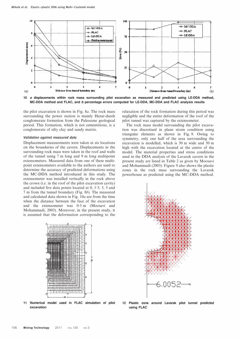
10 a displacements within rock mass surrounding pilot excavation as measured and predicted using LE-DDA method,
MC-DDA method and FLAC, and b percentage errors computed for LE-DDA, MC-DDA and FLAC analysis results
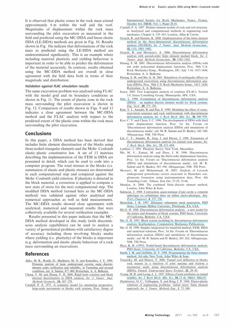
11 Numerical model used in FLAC simulation of pilot
excavation
12 Plastic zone around Lavarak pilot tunnel predicted
using FLAC
Mikola et al. Elastic–plastic DDA using Mohr–Coulomb model
156 Mining Technology 2011 VOL 120 NO 3
It is observed that plastic zones in the rock mass extendapproximately 6 m within the wall and the roof.Magnitudes of displacement within the rock masssurrounding the pilot excavation as measured in thefield and predicted using the MC-DDA and linear elasticDDA (LE-DDA) methods are given in Fig. 10. Resultsshown in Fig. 10a indicate that deformations of the rockmass as predicted using the LE-DDA method areunderestimated significantly. This is an example whereincluding material plasticity and yielding behaviour isimportant in order to be able to predict the deformationof the material accurately. In contrast, results obtainedusing the MC-DDA method are overall in closeagreement with the field data both in terms of theirmagnitude and distribution.
Validation against FLAC simulation results
The same excavation problem was analysed using FLACwith the model grid and its boundary conditions asshown in Fig. 11. The extent of plastic zone in the rockmass surrounding the pilot excavation is shown inFig. 12. Comparison of results shown in Figs. 9 and 12indicates a close agreement between the MC-DDAmethod and the FLAC analysis with respect to thepredicted extent of the plastic zone within the rock masssurrounding the pilot excavation.
ConclusionsIn this paper, a DDA method has been derived thatincludes finite element discretisation of the blocks usingthree-noded triangular elements and the Mohr–Coulombelastic–plastic constitutive law. A set of 13 matricesdescribing the implementation of the FEM in DDA arepresented in detail, which can be used to code into acomputer program. The total stresses in the blocks (i.e.summation of elastic and plastic stresses) are determinedin each computational step and compared against theMohr–Coulomb yield criterion. If plasticity is detected inthe block material, a correction is applied to compute anew state of stress for the next computational step. Themodified DDA method (termed here as the MC-DDAmethod) was validated against other analytical andnumerical approaches as well as field measurements.The MC-DDA results showed close agreements withanalytical, numerical and measured results that werecollectively available for several verification examples.
Results presented in this paper indicate that the MC-DDA method developed in this study (with discontin-uous analysis capabilities) can be used to analyse avariety of geotechnical problems with satisfactory degreeof accuracy including those involving blocky mediawhere yielding (i.e. plasticity) of the blocks is important(e.g. deformation and elastic–plastic behaviour of a rockmass surrounding an excavation).
ReferencesAkky, M. R., Rosidi, D., Madianos, M. N. and Kaneshiro, J. Y. 1994.
Dynamic analysis of large underground caverns using discrete-
element codes verification and reliability, in Tunneling and ground
conditions, (ed. A. Salam), 477–484; Rotterdam, A. A. Balkema.
Cheng, Y. M. and Zhang, Y. H. 2000. Rigid body rotation and block
internal discretization in DDA analysis, Int. J. Numer. Anal.
Methods Geomech., 24, 567–578.
Cundall, P. A. 1971. A computer model for simulating progressive,
large-scale movements in blocky rock systems, Proc. Symp. of
International Society for Rock Mechanics, Nancy, France,
October 4-6, ISRM, Vol. 1, Paper II-18.
Cundall, P. A. 1987. Distinct element models of rock and soil structure,
in Analytical and computational methods in engineering rock
mechanics, Chapter 4, 129–163; London, Allen & Unwin.
Grayeli, R. and Hatami, K. 2008. Implementation of the finite element
method in the three-dimensional discontinuous deformation
analysis (3D-DDA), Int. J. Numer. Anal. Methods Geomechan.,
32, (15), 1883–1902.
Grayeli, R. and Mortazavi, A. 2006. Discontinuous deformation
analysis with second-order finite element meshed block, Int. J.
Numer. Anal. Methods Geomechan., 30, 1545–1561.
Hsiung, S. M. 2001. Discontinuous deformation analysis (DDA) with
nth order polynomial displacement functions, Proc. 38th U.S.
Rock Mechanics Symp., Washington, DC; July 7-10, 1437-1444;
Rotterdam, A. A. Balkema.
Hsiung, S. M. and Shi, G. H. 2001. Simulation of earthquake effects on
underground excavations using discontinuous deformation ana-
lysis (DDA), Proc. 38th U.S. Rock Mechanics Symp., 1413–1420;
Rotterdam, A. A. Balkema.
Itasca. 2005. Fast Lagrangian analysis of continua (FLAC), Version
5.0, Itasca Consulting Group, Minneapolis, MN, USA.
Jing, L. 1998. Formulation of discontinuous deformation analysis
(DDA) – an implicit discrete element model for block systems,
Eng. Geol., 49, 371–381.
Kim, Y. I., Amadei, B. and Pan, E. 1999. Modeling the effect of water,
excavation sequence and rock reinforcement with discontinuous
deformation analysis, Int. J. Rock Mech. Min. Sci., 36, 949–970.
Koo, C. Y. and Chern, J. C. 1996. The development of DDA with third
order displacement function, Proc. 1st Int. Forum on
‘Discontinuous deformation analysis (DDA) and simulations of
discontinuous media’, (ed. M. R. Salami and D. Banks), 342–349;
Albuquerque, NM, TSI Press.
Lin, C. T., Amadei, B., Jung, J. and Dwyer, J. 1996. Extensions of
discontinuous deformation analysis for jointed rock masses, Int.
J. Rock Mech. Min. Sci., 33, 671–694.
Lubliner, J. 1991. Plasticity theory; New York, Macmillan.
Ma, M. Y., Zaman, M. and Zhou, J. H. 1996. Discontinuous
deformation analysis using the third-order displacement function,
Proc. 1st Int. Forum on ‘Discontinuous deformation analysis
(DDA) and simulations of discontinuous media’, (ed. M. R.
Salami and D. Banks), 383–394; Albuquerque, NM, TSI Press.
Moosavi, M. and Mohammadi, H. 2003. Analysis of Lavarak
underground powerhouse cavern excavated in Hezardare con-
glomerate formation using instrumentation data, Proc. 6th
Tunneling Conf., Tehran, Iran Oct. 27-29, 51-66.
Munjiza, A. 2004. The combined finite–discrete element method;
London, John Wiley & Sons.
Salencon, J. 1969. Contraction quasi-statique d’une cavite a symetrie
spherique ou cylindrique dans un milieu elasto-plastique, Ann.
Ports Chaussees, 4, 231–236.
Shewchuk, J. R. 1997. Delaunay refinement mesh generation, PhD
thesis, Carnegie Mellon University, Pittsburgh, PA, USA.
Shi G. H. 1988. Discontinuous deformation analysis – a new model for
the statics and dynamics of block systems, PhD thesis, University
of California, Berkeley, CA, USA.
Shi, G. H. 1993. Block system modeling by discontinuous deformation
analysis; Southampton, Computation Mechanics Publications.
Shi, G. H. 1996. Simplex integration for manifold method, FEM, DDA
and analytical solutions, Proc. 1st Int. Forum on ‘Discontinuous
deformation analysis (DDA) and simulations of discontinuous
media’, (ed. M. R. Salami and D. Banks), 205–262; Albuquerque,
NM, TSI Press.
Shyu, K. K. (1993). Nodal-based discontinuous deformation analysis,
PhD thesis, University of California, Berkeley, CA, USA.
Smith, I. M. and Griffiths, D. V. 1998. Programming the finite element
method, 3rd edn; New York, John Wiley & Sons.
Tsesarsky, M. and Hatzor, Y. 2006. Tunnel roof deflection in blocky
rock masses as a function of joint spacing and friction a
parametric study using discontinuous deformation analysis
(DDA), Tunnell. Underground Space Technol., 21, 29–45.
Yeung, M. R. and Leong, L. L. 1997. Effects of joint attributes on tunnel
stability, Int. J. Rock Mech. Min. Sci., 34, (3–4), 348/e1–348/e18.
Zienkiewicz, O. C., Valliappan, S. and King, I. P. 1969. Elasto-plastic
solutions of engineering problems, ‘initial stress’ finite element
approach, Int. J. Numer. Methods Eng., 1, 75–100.
Mikola et al. Elastic–plastic DDA using Mohr–Coulomb model
Mining Technology 2011 VOL 120 NO 3 157
Related Documents