Success in ELECTRONICS Tom Duncan Success in

Welcome message from author
This document is posted to help you gain knowledge. Please leave a comment to let me know what you think about it! Share it to your friends and learn new things together.
Transcript
Success in
ELECTRONICS
Tom DuncanSuccess in
ELECTRONICS
Success Studybooks
Accounting and Costing
Accounting and Costing : Problems and projectBiology Book – keeping and AccountsBritish History 1760 – 1914British History Since 1760 – 1914Business CalculationsChemistryCommerceCommerce : west African EditionCommunication Economic Geography Economics Economics : West African EditionElectronics Elements of BankingEuropean History 1815 – 1941Financial AccountingFinancial Accounting : Questions and AnswersGeography: Human and RegionalGeography: Physical and MapworkInformation ProcessingInsuranceInvestmentLawManagement : PersonnelMathematicsNutritionOffice PracticeOrganic ChemistryPhysics Principles of AccountingPrinciples of Accounting: Answer BookStatisticsTwentieth Century World Affairs
Success in
ELECTRONICS
Tom Duncan, B. Sc.
JOHN MURRAY
© Tom Duncan 1983
Fisrt published 1983
Reprinted 1984 and 1986 (twice) with revisions; 1987, 1989
All rights reserved. No part of this publication may be
reproduced, copied or transmitted save with the written
permission of John Murray (publisher) Ltd, 50 Albemarle
Street, London WIX 4BD, or in accordance with the
provisions of the Copyright Act 1956 (as amended), or
under the terms of any licence permitting limited copying
issued by The Copyright Licesing Agency, 33 – 34 Alferd
Place, London WCIE 7DP.
Any person who does any anauthorised act in relation to
this publication may be liable to criminal prosecution
and civil claims for damages.
Typesed in Great Britain by
J. W. Arrowsmith Ltd, Bristol BS3 2NT
Made and Printed in Great Britain by
Richard Clay Ltd, Bungay, Suffolk
British Library Cataloguing in Publication Data
Duncan, Tom
Succes in Electronics, - (Success Study books)
1. Electronics 1. Title
537,5 TK7815
ISBN 0 – 7195 – 4015 – 1
Foreword
Success in electronics is intended for anyone who wishes
to gain an understanding of the basic principle of
electronics as they are applied in communication, control
and computer system. Very little previous knowledge of
electricity is assumed, and mathematical requirements are
kept to a minimum. The treatment is practically
orientated and actual devices with their uses are
considered in the hope that the reader may be encouraged
to ‘do’ some electronics. For this reason books on
project work are listed in the Further Reading section at
the end of Part Five of this volume.
While not following any practicular examination
syllabus, the book is appropriate for students taking
GCSE. BTEC (Electronics NII and NIII), City & Guilds and
A-level courses.
Part One deals with Basic Electricity, *Part Two
with Components, Part Three and Four with Linier and
Digital Circuits respectively ( in both discrete
component and integrated circuit form) and in Part Five
an outline is given of some Electronics System. If
desired, Part Four may be taken before Part Three. At the
end of most Units, as an aid to checking progress, there
are Revision Questions and Prblems (mostly numerical).
Answers are given, where appropriate, at the end of the
book.
T. D.
Acknowledgement
For permission to use copyright photograph thanks are dueto: Austin Rover Group Ltd. (Fig. 1.1(a)); Avo Ltd.(2.10); British Telecom (1.1(b), (f)); Computer GamesLtd. (1.1 (e)); Department of Industry (13.5(b));Ferranti Electronics Ltd. (13.1); Maplin Electronics Ltd.
(5.7(a), (b), 6.15(d), 9.9(a), 9.10(a)); Mullard Ltd.(13.3, 13.5(a), 19.10); National Coal Board (1.1(d));National Physical Laboratory (Crown Copyright) (1.1(c));Scopex Instrument Ltd. (20.18); STC PLC (18.30(b));Thandar Electronics Ltd. (20.16).
I should like to thank Edward Mallory, LeslieBasford and Jim Hutton who read and critized the bookduring its preparation. I am also much indebted to Dr.Helen Wright for editing the text so meticulously, toIrene Slade, Anne Webster and Helen Syme of John Murray,to my wife who typed the manuscript and to my daughter,Dr. heather Kennett, for help in various ways.
T. D.
Contens
Part One Basic Electricity
Unit 1 Introduction
1.1 Electronics Today 31.2 Electronics System 31.3 Linier and Digital Circuits 61.4 Electronics Diagrams
71.5 Questions 8
Unit 2 Direct Current
2.1 Electric Current9
2.2 Electromotive Force10
2.3 Circuits and Diagrams10
2.4 Potential Difference11
2.5 Resistance 122.6 Worked Examples 132.7 Ammeters, Voltmeters and Multimeters
142.8 Ohm’s Law 152.9 Electric Charge
162.10 Electrical Energy
172.11 Power 182.12 Internal Reistance
192.13 Revision Question
20
2.14 Problems 20
Unit 3 Alternating Current
3.1 Direct and Alternating Currens23
3.2 Frequency 243.3 Waveforms 243.4 Root Mean Square Values
263.5 Meters for Alternating Current
273.6 Revision Question
273.7 Problems 28
Part Two Components
Units 4 Resistors
4.1 About Resistors31
4.2 Fixed Resistors31
4.3 Resistors Markings32
4.4 Resistors in Series34
4.5 Resistors in Parallel 354.6 Variable Resistors
36
4.7 Potential Dividers37
4.8 Worked Examples 394.9 Revision Questions
414.10 Problems 42
Unit 5 Capacitors
5.1 Electronics Today 445.2 Fixed Capacitors 455.3 Variable Capacitors
465.4 Charging a Capacitor
475.5 Capacitor Networks
485.6 Time Constant
505.7 Capacitive Reactance 525.8 CR Coupled Circuits 545.9 Testing Capacitors 555.10 Worked Examples 565.11 Revision Questions 585.12 Problems 60
Unit 6 Inductors
6.1 About Inductors 616.2 Electricity and Magnetism
626.3 How Inductors Work
646.4 Types of Inductor
656.5 Inductive Reactance
66
6.6 Alternating Current Series Circuit67
6.7 About Transformers69
6.8 Types of Transformer71
6.9 Revision Question71
6.10 Problems 72
Unit 7 Semiconductor Diodes
7.1 About Diodes 737.2 Intrinsic Semiconductors
737.3 Extrinsic Semiconductors
757.4 The p-n Junction 777.5 Junction Diode
787.6 Point- contact Diode
807.7 Zener Diode 807.8 Other Dioders
827.9 Revision Questions
827.10 Problems 83
Unit 8 Transistor
8.1 About Transistors 858.2 Junction Transistors
858.3 Junction Transistor – Current Amplifier
87
8.4 Junction Transistor – Characteristics89
8.5 Junction Transistors – Data91
8.6 Junction Transistors – Testing92
8.7 Field Effect Transistor – JUGFET94
8.8 Field Effect Transistor – MOSFET95
8.9 Comparison of Transistors97
8.10 Revision Questions97
8.11 Problems 98
Unit 9 Transducers and Switches
9.1 About Transducers 1009.2 Microphones 1009.3 Loudspeakers, Headphones and Earpieces 1029.4 Photocells 1059.5 Photodiode and Phototransistor 1069.6 Light Emiting Diode (LED) 1079.7 Liquid Crystal and Others Displays* 1109.8 Chatode Ray Tube (CRT) 1119.9 Thermistors 1139.10 Pick – Ups 1149.11 Relays and Reed Switches 1149.12 Mechanical Switches 1169.13 Revision Questions 1189.14 Problems 119
Part Three Linier Circuits
Unit 10 Basic Audio Frequency Amplifiers
10.1 Introduction 12310.2 Voltage Amplifier using a Junction Transistor 12310.3 Worked Example 12510.4 Load Lines, Operating Point and Voltage Gain 12610.5 Stability and Bias 12810.6 Simple Two-stage Voltage Amplifier 12910.7 Voltage Amplifier using an FET 13110.8 Revision Questions 13210.9 Problems 133
Unit 11 More Audio Frequency Amplifier
11.1 Fully – stabilized Voltage Amplifier 13611.2 Worked Example 13711.3 Feedback Equation 13811.4 Negative Feedback 13911.5 Input and Output Impedances 14111.6 Impedance Matching Circuits 14211.7 Power Amplifiers – Single – ended 14411.8 Powers Amlifier – push – pull 14611.9 Decible Scale 14811.10 Noise 15011.11 Revision Questions 15111.12 Problems 152
Unit 12 Radio Frequency Amplifier and Oscillators
12.1 Introduction 15412.2 Oscillatory Circuit 15412.3 Tuned Circuit 15612.4 Radio Frequency Voltage Amplifier 15712.5 High Frequency Amplifiers 15912.6 Radio Frequency Oscillators 16112.7 Audio Frequency Osccillators 16412.8 Relaxation Oscillators 16512.9 Revision Questions 166
12.10 Problems 167
Unit 13 Operational Amplifiers and Linier Intregated Circuits
13.1 About Integrated Circuits (ICs) 16813.2 Operational Amplifier – introduction 17113.3 Operational Amplifier – practical Points 17313.4 Op Amp as an Inverting Amplifier 17513.5 Op Amp as a Summing Amplifier 17713.6 Op Amp as a Non-inverting Amplifier 17813.7 Op Amp with Single Power Supply 18013.8 Op Amp as a Voltage Comparator 18113.9 Other Linier Integrated Circuits 18113.10 How Linier Integrated Circuits Work 18413.11 Revision Questions 18613.12 Problems 187
Part Four Digital Circuits
Unit 14 Basic Switching Circuits
14.1 Introduction 19114.2 Transistor as a Switch 19114.3 Alarm Circuits 19414.4 Logic Gates – Types 19514.5 Logic Gates – Further Points 19814.6 Multivibrators 19914.7 Bisable of Flip – flop 20014.8 Astable
20114.9 Monostable 20314.10 Triggered Flip – flop 20414.11 Schmitt Trigger 20514.12 Revision Questions 207
14.13 Problems209
Unit 15 Decision – making Circuits
15.1 Introduction 21115.2 About Digital Integrated Circuits 21115.3 Digital Integrated Circuits – Practical Points
21215.4 Logic Gates 21315.5 Codes 21515.6 Encoders
21715.7 Decoders 21815.8 Adders 22015.9 Magnitude Comparators 22315.10 Multiplexer 22515.11 Arithmetic Logic Unit 22715.12 Revision Questions and Problems 229
Unit 16 Memory – type Circuits
16.1 Introduction 23116.2 SR Flip – flop 23216.3 T – type Flip – flop 23416.4 D – type Flip-flop 23516.5 JK Flip-flop 23716.6 Shift Registers 23916.7 Counters
24116.8 Memories 24416.9 Memory Circuits 24616.10 Revision Questions and Problems 248
Unit 17 More Digital Ciruits
17.1 Timers 250
17.2 Digital to – analogue Converter 253
17.3 Analogue – to- digital Converter 25517.4 Op Amp as a Multivibrator 25617.5 Waveform Generators 25917.6 Schmitt Trigger 26017.7 Noise Immunity and Interfacing 26117.8 TTL Circuitry 26317.9 CMOS Circuitry 26517.10 Revision Question and Problem 266
Part Five Electronic Systems
Unit 18 Radio, Television and Audio Systems
18.1 Radio Waves 27118.2 Aerials
27218.3 Amplitude Modulated (AM) Radio 27518.4 Frequency Modulated (FM) Radio 27818.5 Black-and-white Television 28018.6 Colour Television 28418.7 Sound Recording 28618.8 Video Recording 28818.9 Digital Electronics in Communications 29018.10 Optical Fibre System 29218.11 Optical Fibres 29318.12 Optical Transmitters 29618.13 Optical Receivers 29618.14 Revision Questions and Problems 296
Unit 19 Digital System and Computers
19.1 Designing Digital Systems 29919.2 Microelectronic Options 30219.3 Digital Watch 30419.4 Electronic Calculator 30419.5 Digital Computer 30619.6 Microprocessor 31119.7 Analogue Computer 312
19.8 Revision Questions and Problems 316
Unit 20 Power Supplies and Test Instruments
20.1 Introduction 31720.2 Rectifier Circuits 31720.3 Smooting Circuits 31920.4 Stabilizing Circuits 32120.5 Power Control 32320.6 Batteries
32420.7 Multimeters 32620.8 Oscilloscopes 32720.9 Signal Generators 32920.10 Revision Question and Problems 331
Appendix 333
Further Reading 335
Answer to Revision Question and Problems 336
Index 346
Part One
Basic Electricity
Unit One
Introduction
1.1 Electronics Today
Advances in electronics have given us pocket calculators,digital watches, heart pacemarkers, computer forindustry, commerce and scientific research, automaticallycontrolled production processes, instant viewing on ourtelevision screens of events on the other side of theworld and host of other applications.
These have become possible largerly because we haveearned how to build compiete circuits, containingthousands of electronic parts, on a tiny wafer of siliconno more than 5 mm square and 0.5 mm thick.Microelectronic is concerned with these ‘denselypopulated’, miniaturized integrated circuits (ICs), or‘chips’ as they are called, which are changing the way welive and work and challenging us to see that the changesare for the better.
Chips are also used to control robots in factories,electric cookers, washing machines and traffic lights,they are the ‘brains’ behind tv games and microcomputer,they form the hearts of maachiner for teaching spellingand arithmetic and can even be used to mix cocktail andrecognize signatures!
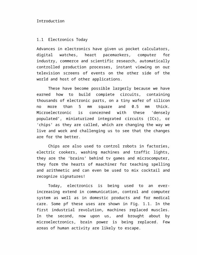
Today, electronics is being used to an ever-increasing extend in communication, control and computersystem as well as in domestic products and for medicalcare. Some pf these uses are shown in Fig. 1.1. In thefirst industrial revolution, machines replaced muscles.In the second, now upon us, and brought about bymicroelectronics, brain power is being replaced. Fewareas of human activity are likely to escape.
1.2 Electronic System
After changing inside a electronics system such as radioor television set or a computer, it would not surprisingif you felt slightly discouraged from studyingelectronics. Fortunately things are really less dauntingthan they seem, for which there are two reasons.
First, while an electronics system may have a largenumber of components (parts), there are only a few typesof these. The main ones are resistors, capacitors,inductors, diodes, transistor, switches and transducters.Those used in integrated circuits (transistors, diodes,resistors and capacitors) have the same action as theirdiscrete (separate) counterparts, they difference ismainly one of size.
Second, different electronics system are made upfrom a fairly small number of basic circuits or buildingblocks. Each basic circuits consist of components
(a)
(b) (c)
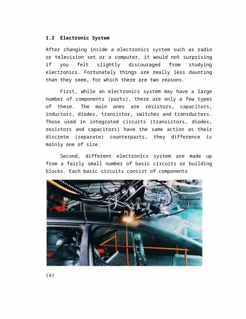
Fig. 1.1 (a) arc welding computer- controlled robots inoperation on a car production line; (b) earth stationdish aerials like this one use microwaves to beamtelephone calls, television pictures and computer data to‘stationary’ satellites 36000 km in space wich amplifyand reroute the signals to particular earth stations oreven to other satellites; (c)signature recognizingprototype equipment;
(d)
(e)
(f)
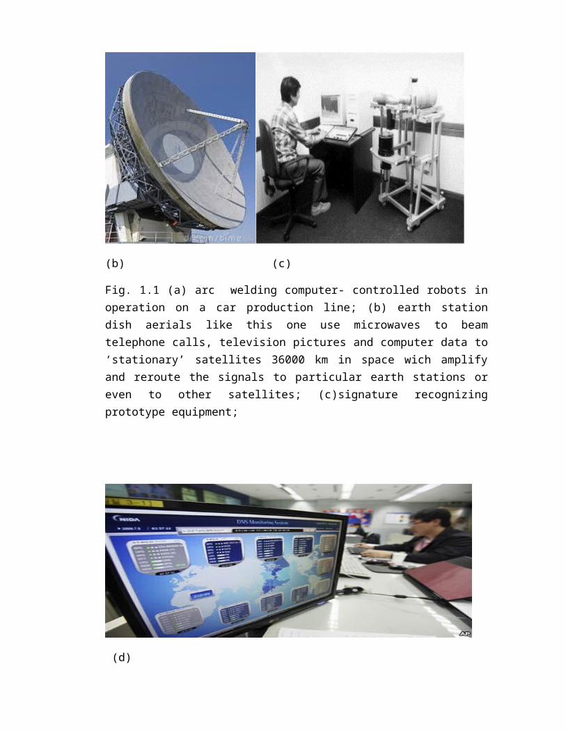
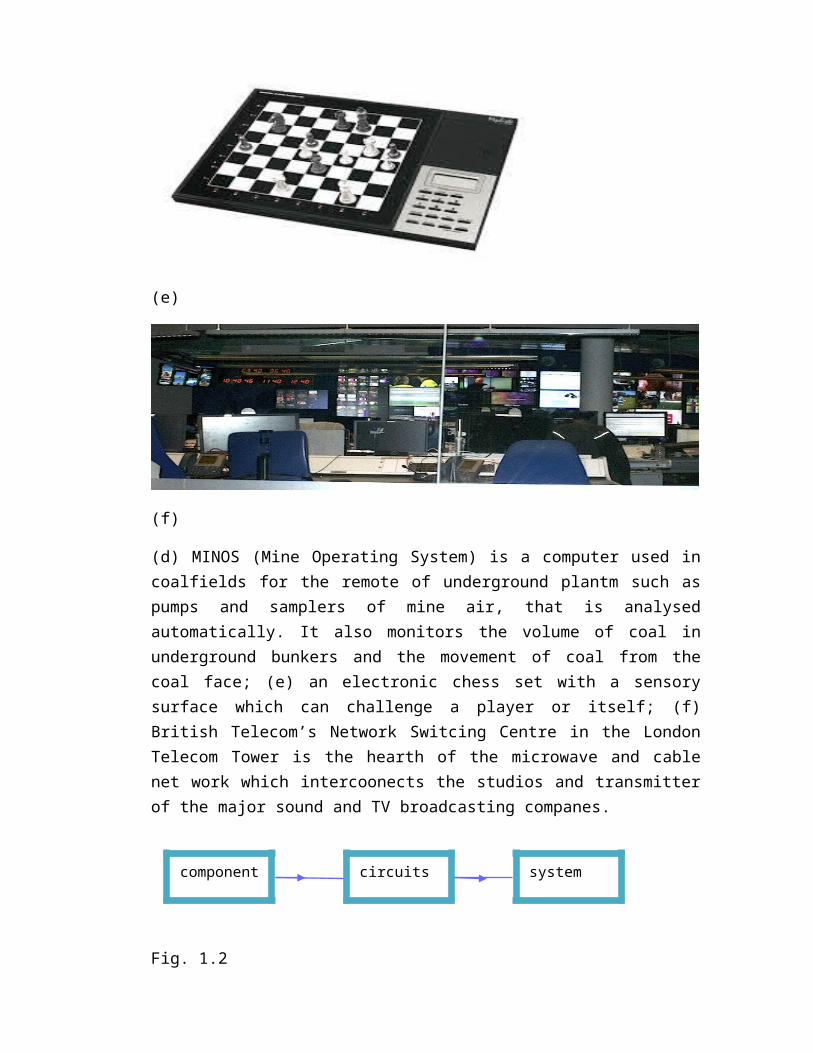
(d) MINOS (Mine Operating System) is a computer used incoalfields for the remote of underground plantm such aspumps and samplers of mine air, that is analysedautomatically. It also monitors the volume of coal inunderground bunkers and the movement of coal from thecoal face; (e) an electronic chess set with a sensorysurface which can challenge a player or itself; (f)British Telecom’s Network Switcing Centre in the LondonTelecom Tower is the hearth of the microwave and cablenet work which intercoonects the studios and transmitterof the major sound and TV broadcasting companes.
Fig. 1.2
components
circuits system
Connected in a certain way so that is does particular jobsuch as amplifiying or counting (fig. 1.2).
Before the days of microelectronics, component weremade separately and then wired together to give therequired circuit. Today they are also produced integratedcircuit form, completed with interconnections, more orles all at the same time. The extend of the integrationis now so great that the distinction between a circuitand system in often less clear-cut. In fact, some chipsquality to be at least sud-system if not quite completesystem. In many cases, system are built from a mixture ofdiscrete components and integrated circuits.
1.3 Linier and Digital Circuits
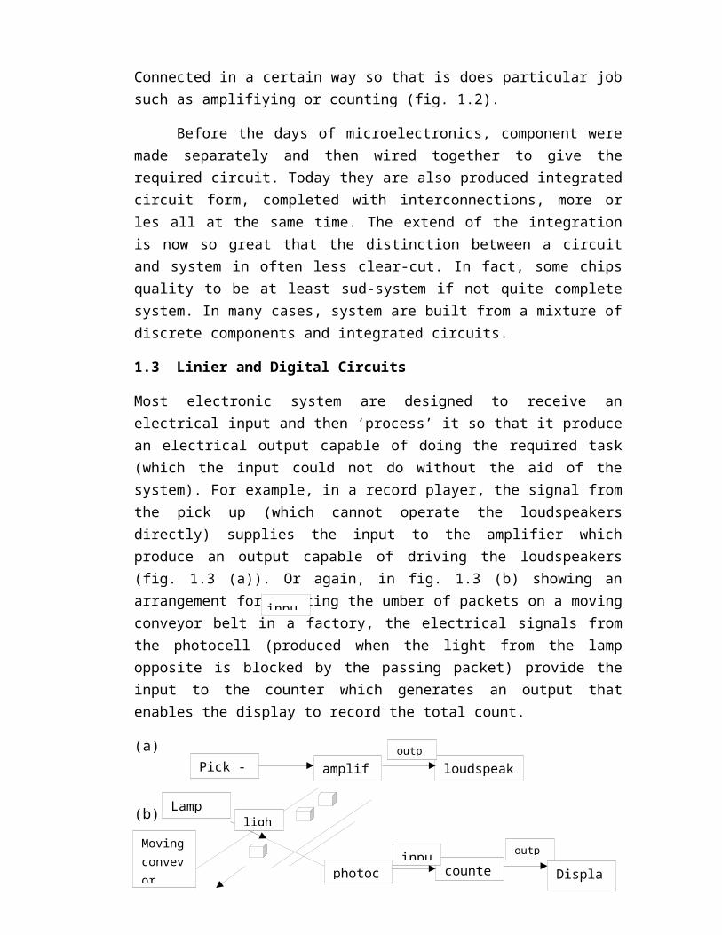
Most electronic system are designed to receive anelectrical input and then ‘process’ it so that it producean electrical output capable of doing the required task(which the input could not do without the aid of thesystem). For example, in a record player, the signal fromthe pick up (which cannot operate the loudspeakersdirectly) supplies the input to the amplifier whichproduce an output capable of driving the loudspeakers(fig. 1.3 (a)). Or again, in fig. 1.3 (b) showing anarrangement for counting the umber of packets on a movingconveyor belt in a factory, the electrical signals fromthe photocell (produced when the light from the lampopposite is blocked by the passing packet) provide theinput to the counter which generates an output thatenables the display to record the total count.
(a)
(b)
Pick - amplif loudspeak
inpu
outp
Lamp
photoc counte Display
inpu
outp
lighMovingconvevor
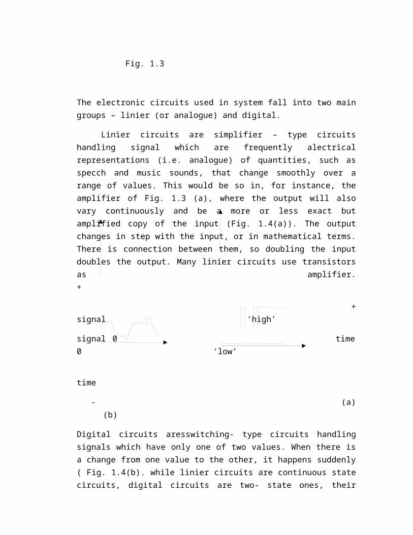
Fig. 1.3
The electronic circuits used in system fall into two maingroups – linier (or analogue) and digital.
Linier circuits are simplifier – type circuitshandling signal which are frequently alectricalrepresentations (i.e. analogue) of quantities, such asspecch and music sounds, that change smoothly over arange of values. This would be so in, for instance, theamplifier of Fig. 1.3 (a), where the output will alsovary continuously and be a more or less exact butamplified copy of the input (Fig. 1.4(a)). The outputchanges in step with the input, or in mathematical terms.There is connection between them, so doubling the inputdoubles the output. Many linier circuits use transistorsas amplifier.+
+signal ‘high’
signal 0 time0 ‘low’
time
- (a)(b)
Digital circuits aresswitching- type circuits handlingsignals which have only one of two values. When there isa change from one value to the other, it happens suddenly( Fig. 1.4(b). while linier circuits are continuous statecircuits, digital circuits are two- state ones, their
inputs and outputs are either ‘high’, i.e. near the valueof the supply, or ‘low’, i.e. near zero. They usetransistors as switches. The counter in fig. 1.3(b) is adigital circuits in which the input from the photocell iseither ‘low’ or ‘high’ depending on whether or not lightis interrupted. Digital circuits carry electrical pulses.
A lamp controlled by a dimmer allows a wide range oflight levels and is a continuous state system. Onecontrolled by an on-off switch is a two-state system; itis either fully alight or it is not alight at all.
Some electronic system contain both linier anddigital circuits.
1.4 Electronic Diagrams
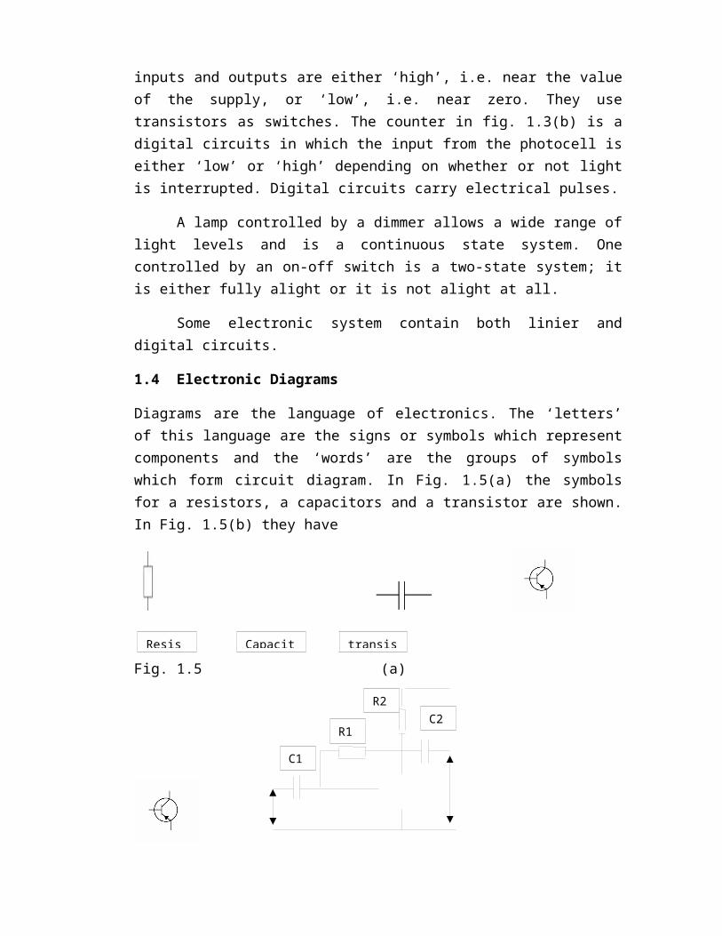
Diagrams are the language of electronics. The ‘letters’of this language are the signs or symbols which representcomponents and the ‘words’ are the groups of symbolswhich form circuit diagram. In Fig. 1.5(a) the symbolsfor a resistors, a capacitors and a transistor are shown.In Fig. 1.5(b) they have
Fig. 1.5 (a)
Resis Capacit transis
C1
C2R1
R2

(b)
Related Documents