EL 675 UHF Propagation for Modern Wireless Systems Henry L. Bertoni Polytechnic University

EL 675 UHF Propagation for Modern Wireless Systems Henry L. Bertoni Polytechnic University.
Dec 21, 2015
Welcome message from author
This document is posted to help you gain knowledge. Please leave a comment to let me know what you think about it! Share it to your friends and learn new things together.
Transcript

EL 675 UHF Propagation for Modern
Wireless Systems
Henry L. Bertoni
Polytechnic University

2003 © 2003 by H.L. Bertoni 2
Context for Discussing Wireless Channel Characteristics
• Frequencies above ~ 300 MHz ( < 1 m)• Radio links in man-made environments
– At least one end is among the buildings
– Link lengths • Macrocells (20 km > R > 1 km)
• Microcells (2 km > R > 100 m)
• Picocells/indoor (R < 100 m)
– Presence of many objects with sizes from 10 cm to 100 m
– Wave interactions described by scattering and shadowing, rather than resonances
2003 © 2003 by H.L. Bertoni 3
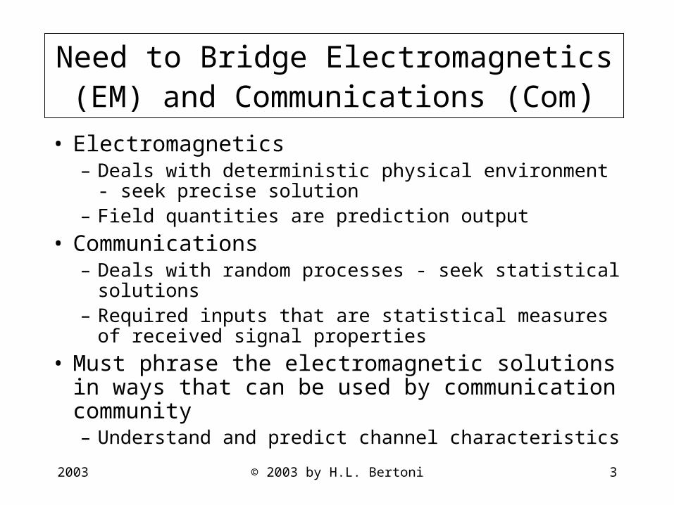
Need to Bridge Electromagnetics (EM) and Communications (Com)
• Electromagnetics– Deals with deterministic physical environment - seek
precise solution– Field quantities are prediction output
• Communications – Deals with random processes - seek statistical solutions – Required inputs that are statistical measures of received
signal properties
• Must phrase the electromagnetic solutions in ways that can be used by communication community– Understand and predict channel characteristics
2003 © 2003 by H.L. Bertoni 4
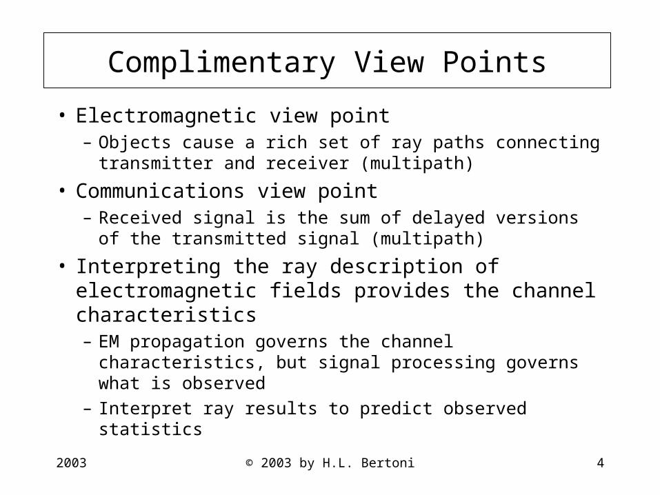
Complimentary View Points
• Electromagnetic view point– Objects cause a rich set of ray paths connecting
transmitter and receiver (multipath)
• Communications view point– Received signal is the sum of delayed versions of the
transmitted signal (multipath)
• Interpreting the ray description of electromagnetic fields provides the channel characteristics– EM propagation governs the channel characteristics,
but signal processing governs what is observed
– Interpret ray results to predict observed statistics

2003 © 2003 by H.L. Bertoni 5
Communication Systems Drive Descriptions of the Radio Channel
• How to characterize channel depends on the radio system and link geometry – All require knowledge of the power level
• Different measures of multipath interference – Narrowband -- pulsed -- multi-frequency systems – Fast fading -- delay spread -- coherence bandwidth– Coherence distance -- angle spread -- ?
• Macrocells, microcells and indoor picocells– Different considerations of multipath interference– Slow fading statistics and range dependence vs. deterministic variations power level

2003 © 2003 by H.L. Bertoni 6
EM Effects That Need to Be Considered
• Propagation of waves through space• Reflection, transmission and diffraction
– Mechanisms by which fields get to locations not visible to the transmitter
• Radiation and reception by antennas• Ray description of radiation
2003 © 2003 by H.L. Bertoni 7
Basic Concepts
• Operation of individual radio systems is dependent on specific channel parameters -- all systems depend on received power and interference.
• Frequency re-use as a basis for increased system capacity

2003 © 2003 by H.L. Bertoni 8
Pre 1980 Vehicular Mobile Telephone System
• Single high base station served entire metropolitan area with Nc frequency channels
• Frequency channels reused in other metropolitan areas
• Because of physical separation, desired signal S much larger than the interfering signal I
IS
~100km~100km

2003 © 2003 by H.L. Bertoni 9
Cellular Mobile Radio:Frequency Re-use Within a Metropolitan Area
• Advanced Mobile Phone System (AMPS) has 395 two-way channels in two 25 MHz bands centered at 850 MHz
• Re-using frequency channels in N sub-regions allows for 395N simultaneous phone calls
395channels395
channels
395channels
MetropolitanRegion
f1
f1
f1
f1
f1
f1
f1
f1
f1
f1f1

2003 © 2003 by H.L. Bertoni 10
Dividing Sub-Regions Into NR Cells Allows Spatial Separation of Cells Using Same Frequency
f1
f7
f4
f5
f2
f3
f6
f4
f6
f5
MTSO
To Telephone Network
CELL SITE
Sub-region
Sub-region
NR = 7 frequency re-use pattern for hexagonal cells in each sub-region
MTSO assigns channelsto mobile and connects totelephone network
2003 © 2003 by H.L. Bertoni 11
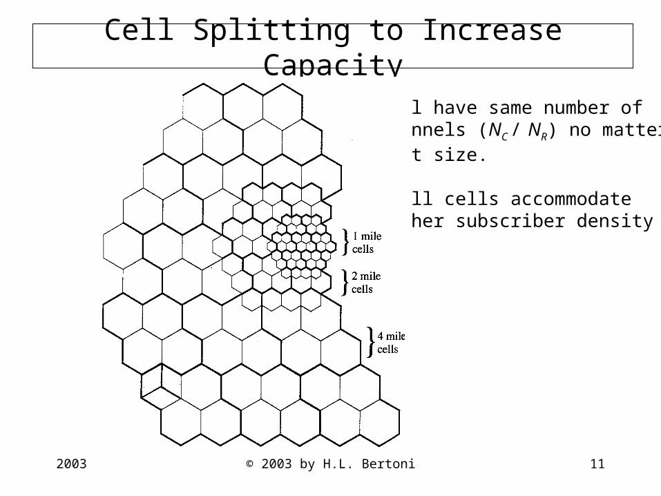
Cell Splitting to Increase Capacity
Cell have same number ofchannels (NC / NR) no matterwhat size.
Small cells accommodatehigher subscriber density

2003 © 2003 by H.L. Bertoni 12
Number of Cells Needed in Each Sub Region
Determined by:
I. Propagation characteristics of the environment
Simplest form of propagation dependence
P = PT A / Rn
P = Received power
PT = Transmitted power
A, n= Amplitude and range index dependent on frequency, antenna height, buildings
II. Minimum signal to interference ratio for adequate reception
by radio system.
For AMPS systems P/ I 50 (10log P/ I > 17dB).
R
2003 © 2003 by H.L. Bertoni 13
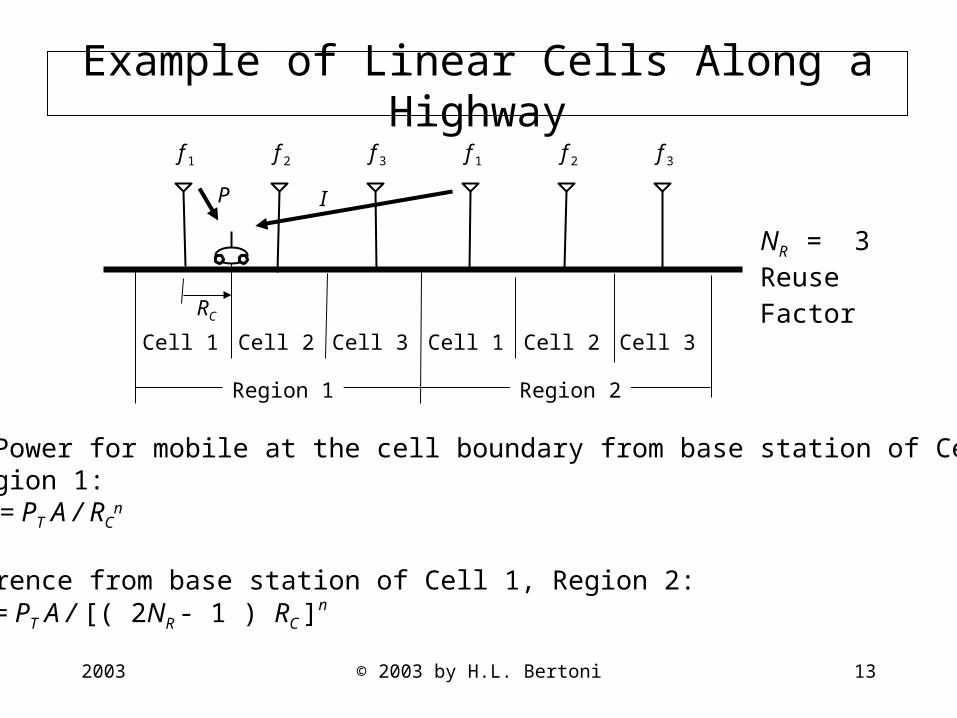
Example of Linear Cells Along a Highway
NR = 3Reuse
Factor
Signal Power for mobile at the cell boundary from base station of Cell 1, Region 1:
P = PT A / RCn
Interference from base station of Cell 1, Region 2:I = PT A / [( 2NR - 1 ) RC ]
n
f 1 f 2 f 3 f 1 f 2 f 3
Region 1 Region 2
Cell 1 Cell 2 Cell 3 Cell 1 Cell 2 Cell 3
RC
IP

2003 © 2003 by H.L. Bertoni 14
NR for Linear Cells for Different Range Index n
€
PI
⎛ ⎝
⎞ ⎠
min
≤PI
=2NR −1( )RC[ ]
n
RCn = 2NR −1( )
n
or
NR ≥12
1+ (P /I)minn[ ]
For (P /I)min =50
Accounting for interference only from the nearest co-channel cell
Condition n NR
Fre e space 2 4Flat e arth 4 2

2003 © 2003 by H.L. Bertoni 15
Frequency Re-Use Pattern for Covering Area
Symmetric patterns based onhexagonal cells have allco-channel cells located on circles.There are six cells on the smallestcircle of radius D, where
For symmetric reuse patterns
where m1, k1 are any integers.Lowest values are NR= 3, 4, 7, 9, 12, 13, 19, 21, 25, 27,31, 39.
2111
21
.3
kkmmN
NRD
R
RC
++=
=
D
RC
Co-channel cellsin the first tier

2003 © 2003 by H.L. Bertoni 16
Frequency Re-Use for S = A/R n Signal Variation
Signal Power from base stations to mobile at the cell edge
P = PT A /(RC)n
Interference power from co-channel base stations in the first tier
D
D+R
C
RC D+R
C
DRC
DRC
D
I =PTA2
D−RC( )n +
2Dn +
2
D+RC( )n
⎡
⎣ ⎢
⎤
⎦ ⎥
2003 © 2003 by H.L. Bertoni 17
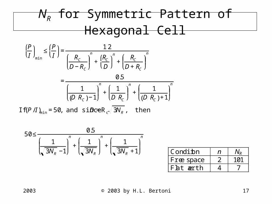
NR for Symmetric Pattern of Hexagonal Cell
€
PI
⎛ ⎝
⎞ ⎠
min
≤PI
⎛ ⎝
⎞ ⎠ =
12
RCD−RC
⎛
⎝ ⎜ ⎞
⎠ ⎟ n
+RCD
⎛ ⎝
⎞ ⎠
n
+RC
D+RC
⎛
⎝ ⎜ ⎞
⎠ ⎟ n
=0.5
1D RC( )−1
⎛
⎝ ⎜ ⎞
⎠ ⎟ n
+1
D RC
⎛
⎝ ⎜ ⎞
⎠ ⎟ n
+1
D RC( )+1
⎛
⎝ ⎜ ⎞
⎠ ⎟ n
If (P /I )min =50, and since D =Rc 3NR , then
50≤0.5
13NR −1
⎛
⎝ ⎜
⎞
⎠ ⎟
n
+1
3NR
⎛
⎝ ⎜
⎞
⎠ ⎟
n
+1
3NR +1
⎛
⎝ ⎜
⎞
⎠ ⎟
n
Condition n NR
Fre e space 2 101Flat e arth 4 7

2003 © 2003 by H.L. Bertoni 18
Interference Limited Cellular Systems
• System design is dependent on the propagation characteristics For signal dependence: S = A/ Rn
Free space propagation:
n = 2 and NR will be large (NR = 101)
Propagation over flat earth:
n = 4 and NR = 7
For Cellular Mobile Radio, NC ~ 400
n Channels / cell Base Station/1,000 Calls
2 ~ 4 ~2504 ~ 60 ~16

2003 © 2003 by H.L. Bertoni 19
Use Sectored Cells to Account forRealistic Propagation Laws
• Range index n is between 3 and 4 for elevated base stationantenna
• Additional random fading of the signal exists• Use sectored cells to achieve P/ I > 50• Three sectors per cell is variation of NR= 21 frequency re-use
pattern.
2 3
1
2 3
1
Patterns for cell sectorization using directive antennas.Single base station serves three sectors.

2003 © 2003 by H.L. Bertoni 20
Effect of Range Index n on Down Link System Capacity for CDMA System
• Same frequency used to communicate to subscribers in all cells.
• Different code used for each subscriber.
• Signals to subscribers in other cells act as interference.
• Subscribers in same cells have orthogonal codes, but multipath
interference results in some interference.
• Subscriber can receive same signal from up to three base stations.
• For adequate reception, I FP, where the value of F > 1 depends processing gain, voice activity factor, etc.
2003 © 2003 by H.L. Bertoni 21
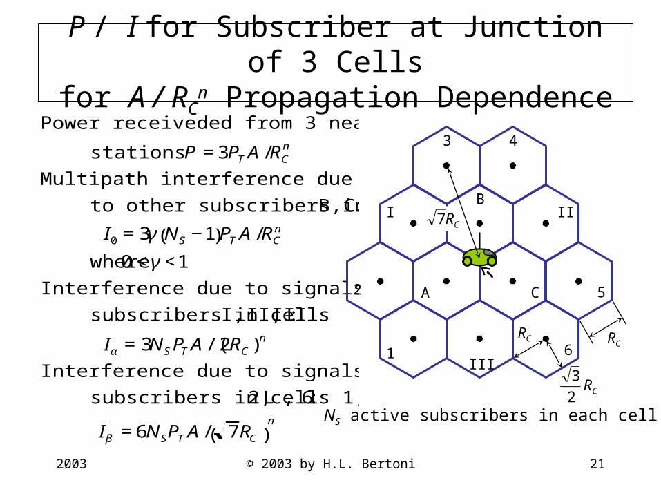
P / I for Subscriber at Junction of 3 Cellsfor A / RC
n Propagation Dependence
€
Power receiveded from 3 nearest base
stations: P =3PTA/RCn
Multipath interference due signals sent
to other subscribers in cells A, B, C:
I0 =3γ NS −1( )PTA/RCn
where 0<γ<1
Interference due to signals sent to
subscribers in cells I, II, III :
Iα =3NSPTA/(2RC)n
Interference due to signals to
subscribers in cells 1, 2, L , 6:
Iβ =6NSPTA/ 7RC( )n NS active subscribers in each cell
CR2
3
1
2
3 4
5
6
A
B
C
I II
III
RC
CR7
RC

2003 © 2003 by H.L. Bertoni 22
Interference Power Received From Base Stations Outside of the Closest 12
€
Smear out base stations over an infinite
disk with a hole of radius R1 to
achieve a transmitted power density
PD = NSPT/(area of a cell).
Area of cell = 3 32
RC2 so that
PD =2
3 3
NSPTRC
2
To find the radius of the hole, set the area
of the hole πRc2 equal to the area of the
12 cells. Thus
R1 =32 3π
RC =3.150RC
CR2
3
1
2
3 4
5
6
A
B
C
I II
III
CR7
RC
R1
2003 © 2003 by H.L. Bertoni 23
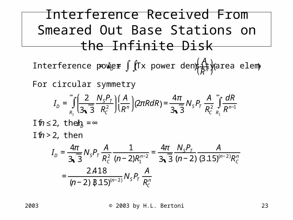
Interference Received From Smeared Out Base Stations on the Infinite Disk
€
Interference power = ID = Tx power density( )∫∫ ARn
⎛ ⎝
⎞ ⎠
area element( )
For circular symmetry
ID =2
3 3
NSPTRC
2
⎛
⎝ ⎜ ⎞
⎠ ⎟
R1
∞
∫ ARn
⎛ ⎝
⎞ ⎠
2πRdR( ) =4π
3 3NSPT
ARC
2
dRRn−1
R1
∞
∫
If n≤2, then ID =∞
If n>2, then
ID =4π3 3
NSPTARC
2
1(n−2)R1
n−2 =4π3 3
NSPT(n−2)
A(3.15)(n−2)RC
n
=2.418
(n−2)(3.15)(n−2)NSPTARCn
2003 © 2003 by H.L. Bertoni 24
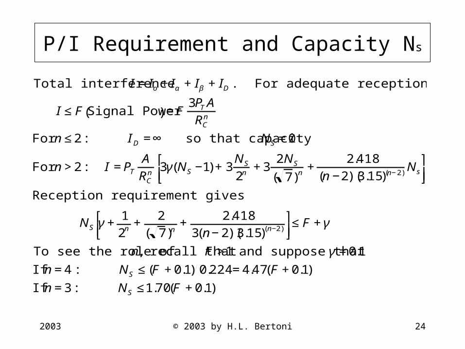
€
Total interference I =Io +Iα +Iβ +ID . For adequate reception
I ≤F Signal Power( ) =F3PTARCn
For n≤2: ID =∞ so that capacity NS =0
For n>2: I =PTARCn 3γ(NS −1)+3
NS
2n+3
2NS
( 7)n+
2.418(n−2)(3.15)(n−2)Ns
⎡
⎣ ⎢ ⎤
⎦ ⎥
Reception requirement gives
NS γ+12n
+2
( 7)n+
2.4183(n−2)(3.15)(n−2)
⎡
⎣ ⎢ ⎤
⎦ ⎥ ≤F +γ
To see the role of n, recall that F >1 and suppose that γ=0.1
If n=4: NS ≤(F +0.1) 0.224=4.47(F +0.1)
If n=3: NS ≤1.70(F +0.1)
P/I Requirement and Capacity Ns
2003 © 2003 by H.L. Bertoni 25
Conclusions
Modern systems employ frequency re-use to increase capacity
Wireless systems employing frequency re-use are interference limited
It is necessary to balance coverage and interference
Design of Systems to accommodate a given number of subscribers is dependent on the propagation characteristics
Higher values of range index n allow for less base stations to cover a given area
Other channel characteristics will influence system design
Random spatial fading
Doppler spread, time delay spread
Related Documents