EASTERN KENTUCKY UNIVERSITY DIVISION OF PURCHASES & STORES RICHMOND, KENTUCKY Replacement of Model Lab Arts HVAC EKU-33-20 DATE: 06/24/19 ADDENDUM NO: Two (2) PLEASE NOTE THE FOLLOWING CHANGES: General Clarification Addenda Item No. 1: Project Schedule Clarification. 1. First day of school is August 14, 2019. 2. The contractor shall complete his work in the mechanical room to minimize downtime of the building’s central hot-chilled water system. If system downtime is anticipated after school start, contractor shall notify EKU project manager at pre-construction kickoff meeting. Item No. 2: Under a separate project, EKU has added spray-on insulation to the exposed sawtooth ceiling in Allied Arts Room #159. This project’s contractor shall cut into insulation in a workmanlike manner, as required to install new hangers, etc. from ceiling structure. EKU will patch and repair ceiling insulation where removed by contractor. Coordinate all patching with EKU project manager. Specifications Addenda Item No. 1: Refer to Specification Section 01 21 00 – Allowances. 1. Omit Paragraph 3.3.A.7. Item No. 2: Refer to Specification Section 01 23 00 – Alternates. 1. In paragraph 3.1.A.2, replace “(4) weeks” and “4 weeks” with 15 days. Item No. 3: Add the attached Specification Section 23 05 19 – Meters and Gages for HVAC Piping. Item No. 4: Refer to Specification Section 23 05 53 – Identification for HVAC Piping and Equipment. 1. Omit paragraphs 1.1.A.3 and 1.1.A.4. 2. Omit paragraph 2.2 – Pipe Labels. 3. Omit paragraph 2.3 – Duct Labels. 4. Omit paragraphs 3.3 and 3.4. Item No. 5: Refer to Specification Section 23 07 13 – Duct Insulation. 1. Clarification. The requirements for internally insulated ductwork are specified in Section 23 31 13 – Metal Ducts. The requirements for externally insulated ductwork are specified in Section 23 07 13 – Metal Ducts. 2. In paragraph 1.1.A.1, replace “outdoor” with “supply and outside.” 3. In paragraph 1.1.A.2, replace “return” with “return air.” 4. In paragraph 3.9.A, replace “outdoor” with “outside.”

Welcome message from author
This document is posted to help you gain knowledge. Please leave a comment to let me know what you think about it! Share it to your friends and learn new things together.
Transcript
EASTERN KENTUCKY UNIVERSITY
DIVISION OF PURCHASES & STORES RICHMOND, KENTUCKY
Replacement of Model Lab Arts HVAC
EKU-33-20
DATE: 06/24/19 ADDENDUM NO: Two (2)
PLEASE NOTE THE FOLLOWING CHANGES: General Clarification Addenda Item No. 1: Project Schedule Clarification. 1. First day of school is August 14, 2019. 2. The contractor shall complete his work in the mechanical room to minimize downtime of the building’s central hot-chilled water system. If system downtime is anticipated after school start, contractor shall notify EKU project manager at pre-construction kickoff meeting. Item No. 2: Under a separate project, EKU has added spray-on insulation to the exposed sawtooth ceiling in Allied Arts Room #159. This project’s contractor shall cut into insulation in a workmanlike manner, as required to install new hangers, etc. from ceiling structure. EKU will patch and repair ceiling insulation where removed by contractor. Coordinate all patching with EKU project manager. Specifications Addenda Item No. 1: Refer to Specification Section 01 21 00 – Allowances.
1. Omit Paragraph 3.3.A.7. Item No. 2: Refer to Specification Section 01 23 00 – Alternates.
1. In paragraph 3.1.A.2, replace “(4) weeks” and “4 weeks” with 15 days. Item No. 3: Add the attached Specification Section 23 05 19 – Meters and Gages for HVAC Piping. Item No. 4: Refer to Specification Section 23 05 53 – Identification for HVAC Piping and Equipment.
1. Omit paragraphs 1.1.A.3 and 1.1.A.4. 2. Omit paragraph 2.2 – Pipe Labels. 3. Omit paragraph 2.3 – Duct Labels. 4. Omit paragraphs 3.3 and 3.4.
Item No. 5: Refer to Specification Section 23 07 13 – Duct Insulation. 1. Clarification. The requirements for internally insulated ductwork are specified in Section 23 31 13 – Metal Ducts. The requirements for externally insulated ductwork are specified in Section 23 07 13 – Metal Ducts. 2. In paragraph 1.1.A.1, replace “outdoor” with “supply and outside.” 3. In paragraph 1.1.A.2, replace “return” with “return air.” 4. In paragraph 3.9.A, replace “outdoor” with “outside.”
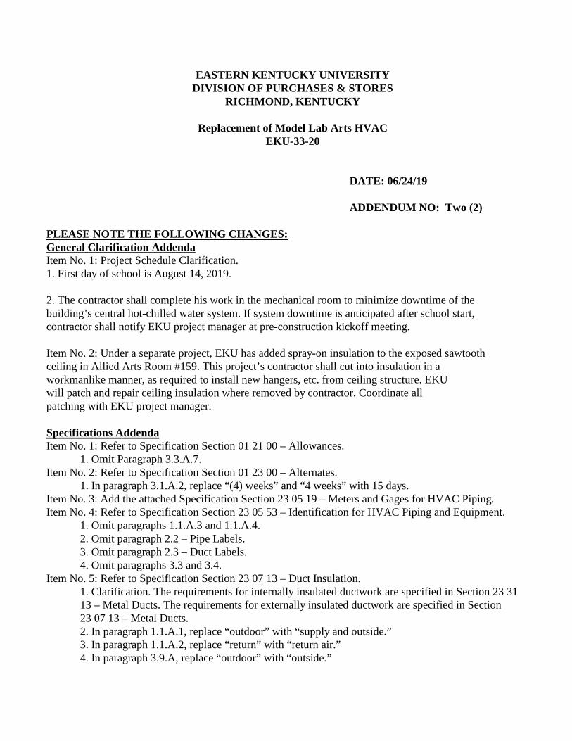
5. Add the following new paragraph 3.9.B:
1. Exposed supply air duct: Internal duct liner. Refer to Specification Section 23 31 13 – Metal Ducts.
Item No. 6: Refer to Specification Section 23 07 19 – HVAC Piping Insulation. 1. Add the following new paragraph 1.1.A.3:
1. Hot-Chilled water piping, indoors. 2. Add the following new paragraph 3.8.D:
1. Hot-Chilled water piping: Flexible elastomeric, 1/2-inch thick up to 1-1/4” pipe size, and 1” thick above 1-1/4” pipe size.
Item No. 7: Refer to Specification Section 23 21 13 – Hydronic Piping. 1. Replace paragraph 3.1.F.2 in its entirety with the following text:
1. Schedule 40 steel pipe; Class 150, malleable-iron fittings; cast-iron fittings; cast-iron flanges and flange fittings; and threaded joints.
Item No. 8: Refer to Specification Section 23 21 16 – Hydronic Piping Specialties. 1. Add the following new paragraph 3.2.C:
1. Install 3/4" drain piping with line size ball valve from strainer drain connection and spill at nearby floor drain. Install piping in workmanlike manner to avoid trip hazard.
Item No. 9: Refer to Specification Section 23 31 13 – Metal Ducts. 1. In paragraph 3.8.D.1, replace “2 inches thick” with “1 inch thick”. 2. In paragraph 3.8.D.2, replace “2 inches thick” with “1 inch thick”.
Item No. 10: Refer to Specification Section 23 74 16.13 – Packaged, Large-Capacity, Rooftop Air-conditioning units.
1. Replace the section with the revised, attached section dated 6/21/2019. Item No. 11: Refer to Specification Section 23 81 26 – Split-System Air Conditioners.
1. Replace the section with the revised, attached section dated 6/21/2019. Item No. 12: Refer to Specification Section 23 82 19 – Fan Coil Units.
1. Omit paragraph 2.2.J and sub paragraphs. Item No. 13: Refer to Specification Section 26 05 19 – Low-voltage Electrical Power Conductors and Cables.
1. Omit paragraph 1.1.A.2. Drawings Addenda - Item No. 1: Refer to Drawing Sheet MD1.0 – Partial First Floor Mechanical Demolition.
1. Clarification. The exhaust ductwork above ceiling in Finish & Paint Storage 159G shall remain. Contractor shall cap exhaust ductwork at exterior wall per Sheet Note #7. 2. In Storage 159, there is an abandoned 1/2” pipe that runs above doorway, along wall. Remove pipe and hangers complete, to allow for new duct work installation at ceiling.
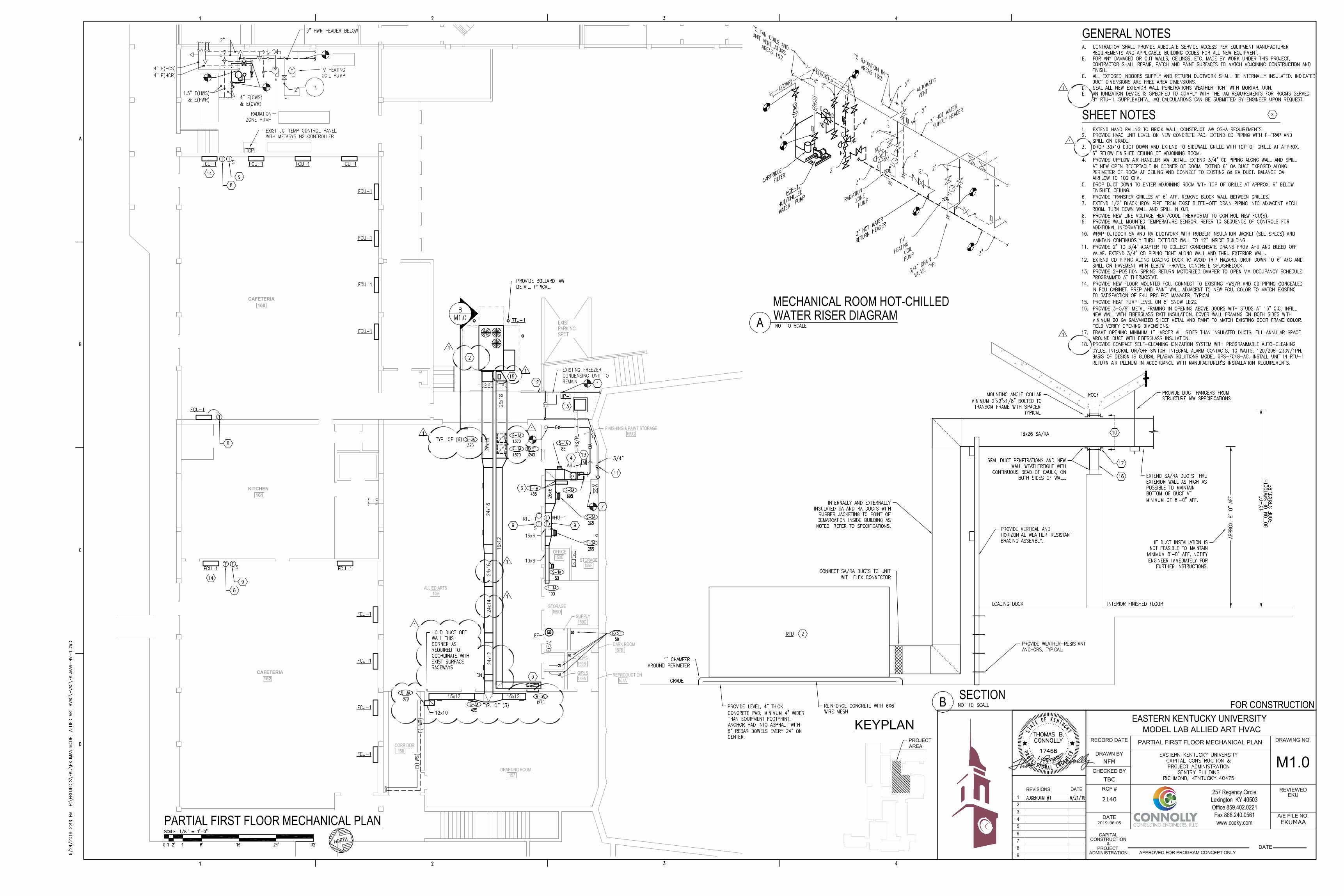
Item No. 2: Refer to Drawing Sheet M1.0 – Partial First Floor Mechanical Plan. 1. Refer to attached drawing for additional revisions.
Item No. 3: Refer to Drawing Sheet M3.0 –Mechanical Schedules. 1. In the Grille, Register, & Diffuser Schedule, revise R-3/R-3A to have a grille size and runout size of 30x10.
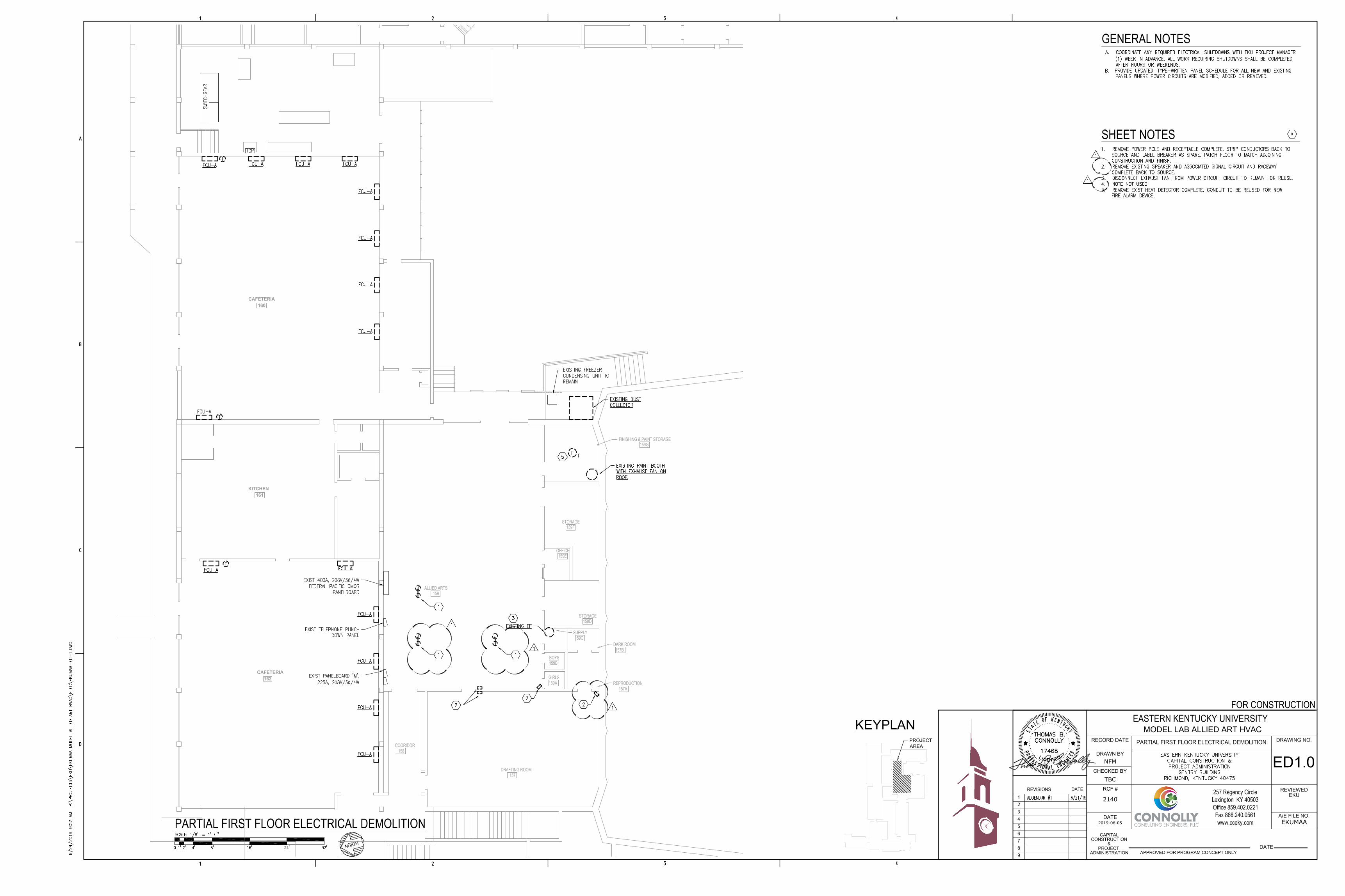
Item No. 4: Refer to Drawing Sheet ED1.0 – Partial First Floor Electrical Demolition. 1. Refer to attached drawing for revisions.
Item No. 5: Refer to Drawing Sheet E1.0 – Partial First Floor Electrical Plan.
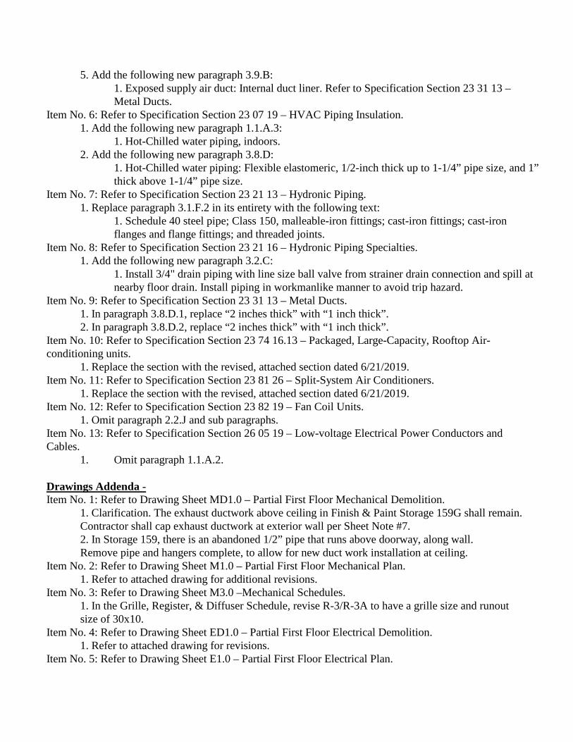
1. Omit Sheet Note #4. Under the ceiling insulation project, EKU will reinstall the suspended light fixtures, and coordinate their installation with the new ductwork. 2. In Allied Arts 159, lower existing exit sign above double doors to avoid conflict with new ductwork.
PLEASE NOTE THE FOLLOWING QUESTIONS/ANSWERS: Q1: Who provides the motorized damper associated with AHU-1 split system – Johnson Controls (JCI) or mech contractor? A1: Mechanical contractor shall provide. This damper is controlled locally via the stand-alone thermostat. No interface with the BAS is required. Q2: Who provides thermostats for new fan coil units – JCI via controls allowance or mech contractor? A2: Mechanical contractor shall provide. Q3: Who provides new 3-way valves in mechanical room – JCI via controls allowance or mech contractor? A3: Mechanical contractor shall provide. All new 3-way valves shall be manual type. Q4: Does the spray-on ceiling insulation in Allied Arts 159 need to be removed to install new ductwork at bottom of sawtooth ceiling? A4: No. Install ductwork as high as possible without removing ceiling insulation. See General Clarification Note below for additional information. Offeror must acknowledge receipt of this and any addenda either with bid, via email to [email protected], or by separate letter. Acknowledgement must be received in the Department of University Procurement, Commonwealth Bldg, 14th Floor, Rm 1411, Richmond, KY not later than June 27, 2019, 10:00 AM (ET). If by separate letter, the following information must be placed in the lower left hand corner of the envelope. BID NUMBER: EKU-33-20 Receipt Acknowledged DUE DATE: June 27, 2019 ___________________________ (Firm Name) DUE TIME: 10:00 AM (ET) ___________________________ (Signature)

Model Allied Art - HVAC June 21, 2019Eastern Kentucky UniversityRichmond, Kentucky
METERS AND GAGES FOR HVAC PIPING 23 05 19 - 1
SECTION 230519 - METERS AND GAGES FOR HVAC PIPING
PART 1 - GENERAL
1.1 SUMMARY
A. Section Includes:1. Liquid-in-glass thermometers.2. Thermowells.3. Dial-type pressure gages.4. Gage attachments.
1.2 ACTION SUBMITTALS
A. Product Data: For each type of product.
1.3 INFORMATIONAL SUBMITTALS
A. Product Certificates: For each type of meter and gage.
1.4 CLOSEOUT SUBMITTALS
A. Operation and maintenance data.
PART 2 - PRODUCTS
2.1 LIQUID-IN-GLASS THERMOMETERS
A. Metal-Case, Industrial-Style, Liquid-in-Glass Thermometers:
1. Manufacturers: Subject to compliance with requirements, available manufacturersoffering products that may be incorporated into the Work include, but are not limited tothe following:a. Flo Fab inc.b. Miljoco Corporation.c. Plamer Wahl Instrumentation Group.d. Winters Instruments – U.S.
2. Standard: ASME B40.200.3. Case: Cast aluminum; 9-inch nominal size unless otherwise indicated.4. Case Form: Adjustable angle unless otherwise indicated.5. Tube: Glass with magnifying lens and blue organic liquid.6. Tube Background: Nonreflective aluminum with permanently etched scale markings
graduated in deg F.7. Window: Glass.8. Stem: Aluminum and of length to suit installation.
a. Design for Air-Duct Installation: With ventilated shroud.
Model Allied Art - HVAC June 21, 2019Eastern Kentucky UniversityRichmond, Kentucky
METERS AND GAGES FOR HVAC PIPING 23 05 19 - 2
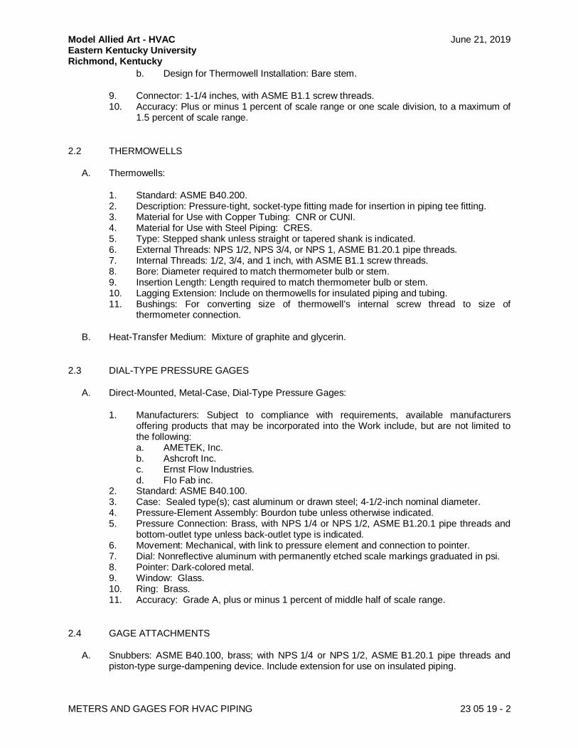
b. Design for Thermowell Installation: Bare stem.
9. Connector: 1-1/4 inches, with ASME B1.1 screw threads.10. Accuracy: Plus or minus 1 percent of scale range or one scale division, to a maximum of
1.5 percent of scale range.
2.2 THERMOWELLS
A. Thermowells:
1. Standard: ASME B40.200.2. Description: Pressure-tight, socket-type fitting made for insertion in piping tee fitting.3. Material for Use with Copper Tubing: CNR or CUNI.4. Material for Use with Steel Piping: CRES.5. Type: Stepped shank unless straight or tapered shank is indicated.6. External Threads: NPS 1/2, NPS 3/4, or NPS 1, ASME B1.20.1 pipe threads.7. Internal Threads: 1/2, 3/4, and 1 inch, with ASME B1.1 screw threads.8. Bore: Diameter required to match thermometer bulb or stem.9. Insertion Length: Length required to match thermometer bulb or stem.10. Lagging Extension: Include on thermowells for insulated piping and tubing.11. Bushings: For converting size of thermowell's internal screw thread to size of
thermometer connection.
B. Heat-Transfer Medium: Mixture of graphite and glycerin.
2.3 DIAL-TYPE PRESSURE GAGES
A. Direct-Mounted, Metal-Case, Dial-Type Pressure Gages:
1. Manufacturers: Subject to compliance with requirements, available manufacturersoffering products that may be incorporated into the Work include, but are not limited tothe following:a. AMETEK, Inc.b. Ashcroft Inc.c. Ernst Flow Industries.d. Flo Fab inc.
2. Standard: ASME B40.100.3. Case: Sealed type(s); cast aluminum or drawn steel; 4-1/2-inch nominal diameter.4. Pressure-Element Assembly: Bourdon tube unless otherwise indicated.5. Pressure Connection: Brass, with NPS 1/4 or NPS 1/2, ASME B1.20.1 pipe threads and
bottom-outlet type unless back-outlet type is indicated.6. Movement: Mechanical, with link to pressure element and connection to pointer.7. Dial: Nonreflective aluminum with permanently etched scale markings graduated in psi.8. Pointer: Dark-colored metal.9. Window: Glass.10. Ring: Brass.11. Accuracy: Grade A, plus or minus 1 percent of middle half of scale range.
2.4 GAGE ATTACHMENTS
A. Snubbers: ASME B40.100, brass; with NPS 1/4 or NPS 1/2, ASME B1.20.1 pipe threads andpiston-type surge-dampening device. Include extension for use on insulated piping.
Model Allied Art - HVAC June 21, 2019Eastern Kentucky UniversityRichmond, Kentucky
METERS AND GAGES FOR HVAC PIPING 23 05 19 - 3
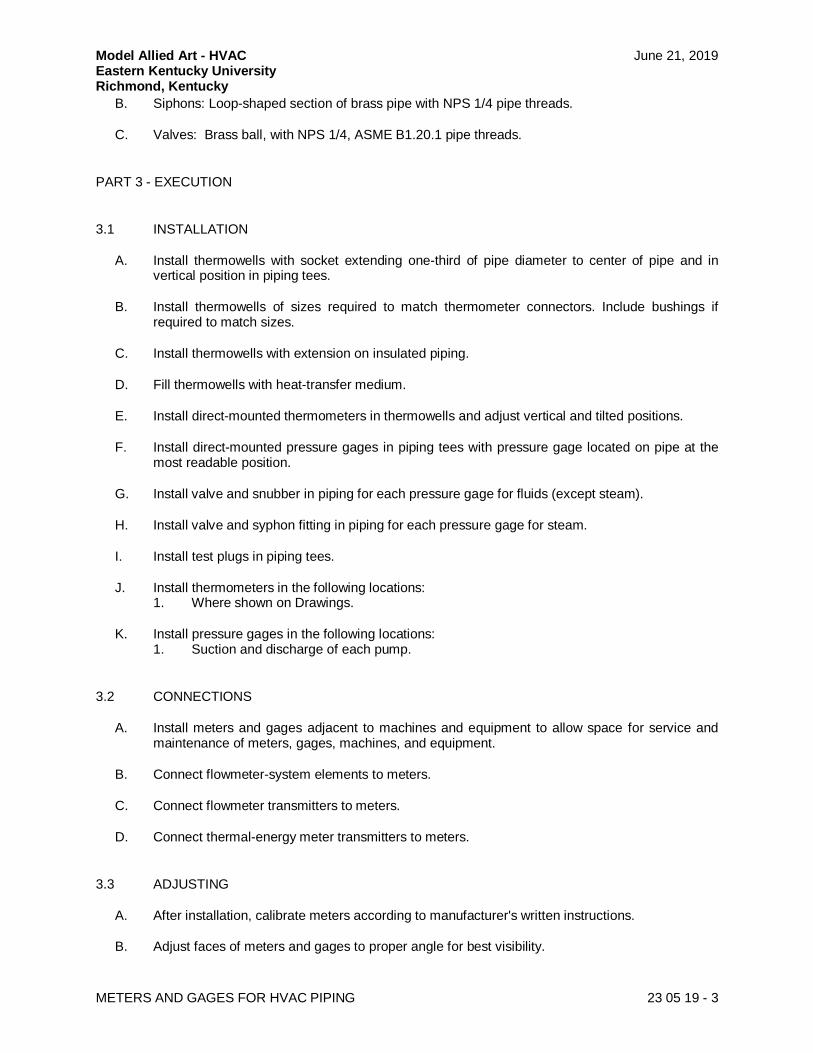
B. Siphons: Loop-shaped section of brass pipe with NPS 1/4 pipe threads.
C. Valves: Brass ball, with NPS 1/4, ASME B1.20.1 pipe threads.
PART 3 - EXECUTION
3.1 INSTALLATION
A. Install thermowells with socket extending one-third of pipe diameter to center of pipe and invertical position in piping tees.
B. Install thermowells of sizes required to match thermometer connectors. Include bushings ifrequired to match sizes.
C. Install thermowells with extension on insulated piping.
D. Fill thermowells with heat-transfer medium.
E. Install direct-mounted thermometers in thermowells and adjust vertical and tilted positions.
F. Install direct-mounted pressure gages in piping tees with pressure gage located on pipe at themost readable position.
G. Install valve and snubber in piping for each pressure gage for fluids (except steam).
H. Install valve and syphon fitting in piping for each pressure gage for steam.
I. Install test plugs in piping tees.
J. Install thermometers in the following locations:1. Where shown on Drawings.
K. Install pressure gages in the following locations:1. Suction and discharge of each pump.
3.2 CONNECTIONS
A. Install meters and gages adjacent to machines and equipment to allow space for service andmaintenance of meters, gages, machines, and equipment.
B. Connect flowmeter-system elements to meters.
C. Connect flowmeter transmitters to meters.
D. Connect thermal-energy meter transmitters to meters.
3.3 ADJUSTING
A. After installation, calibrate meters according to manufacturer's written instructions.
B. Adjust faces of meters and gages to proper angle for best visibility.
Model Allied Art - HVAC June 21, 2019Eastern Kentucky UniversityRichmond, Kentucky
METERS AND GAGES FOR HVAC PIPING 23 05 19 - 4
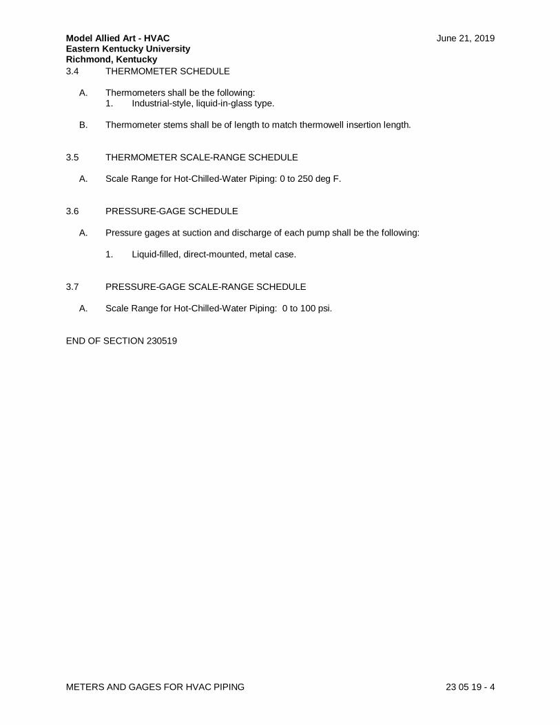
3.4 THERMOMETER SCHEDULE
A. Thermometers shall be the following:1. Industrial-style, liquid-in-glass type.
B. Thermometer stems shall be of length to match thermowell insertion length.
3.5 THERMOMETER SCALE-RANGE SCHEDULE
A. Scale Range for Hot-Chilled-Water Piping: 0 to 250 deg F.
3.6 PRESSURE-GAGE SCHEDULE
A. Pressure gages at suction and discharge of each pump shall be the following:
1. Liquid-filled, direct-mounted, metal case.
3.7 PRESSURE-GAGE SCALE-RANGE SCHEDULE
A. Scale Range for Hot-Chilled-Water Piping: 0 to 100 psi.
END OF SECTION 230519
Model Allied Art - HVAC June 21, 2019Eastern Kentucky UniversityRichmond, Kentucky
PACKAGED, LARGE-CAPACITY, ROOFTOP AIR-CONDITIONING UNITS 23 74 16.13 - 1
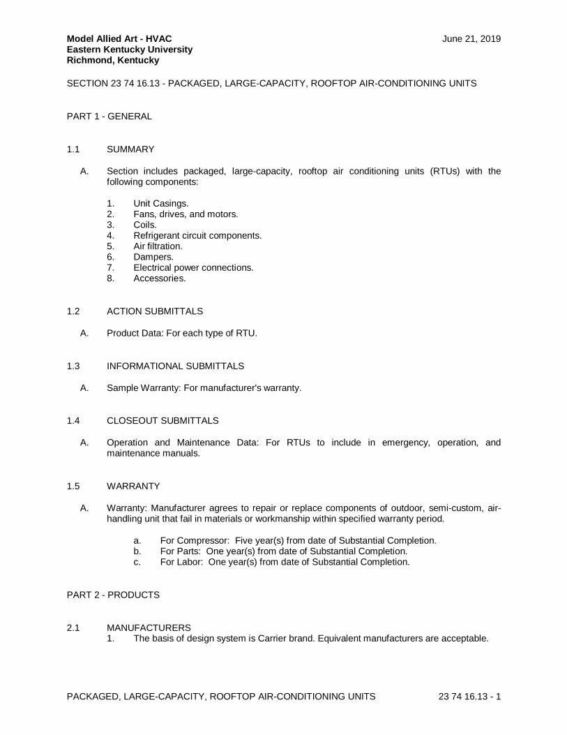
SECTION 23 74 16.13 - PACKAGED, LARGE-CAPACITY, ROOFTOP AIR-CONDITIONING UNITS
PART 1 - GENERAL
1.1 SUMMARY
A. Section includes packaged, large-capacity, rooftop air conditioning units (RTUs) with thefollowing components:
1. Unit Casings.2. Fans, drives, and motors.3. Coils.4. Refrigerant circuit components.5. Air filtration.6. Dampers.7. Electrical power connections.8. Accessories.
1.2 ACTION SUBMITTALS
A. Product Data: For each type of RTU.
1.3 INFORMATIONAL SUBMITTALS
A. Sample Warranty: For manufacturer's warranty.
1.4 CLOSEOUT SUBMITTALS
A. Operation and Maintenance Data: For RTUs to include in emergency, operation, andmaintenance manuals.
1.5 WARRANTY
A. Warranty: Manufacturer agrees to repair or replace components of outdoor, semi-custom, air-handling unit that fail in materials or workmanship within specified warranty period.
a. For Compressor: Five year(s) from date of Substantial Completion.b. For Parts: One year(s) from date of Substantial Completion.c. For Labor: One year(s) from date of Substantial Completion.
PART 2 - PRODUCTS
2.1 MANUFACTURERS1. The basis of design system is Carrier brand. Equivalent manufacturers are acceptable.
Model Allied Art - HVAC June 21, 2019Eastern Kentucky UniversityRichmond, Kentucky
PACKAGED, LARGE-CAPACITY, ROOFTOP AIR-CONDITIONING UNITS 23 74 16.13 - 2
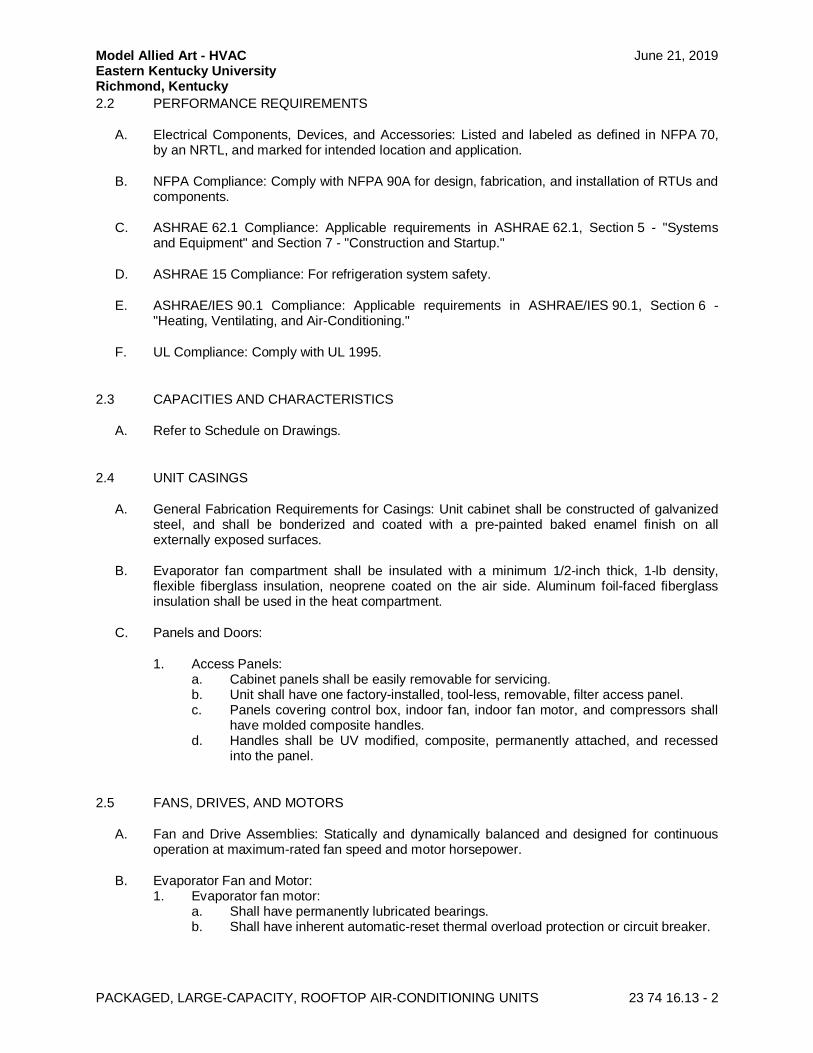
2.2 PERFORMANCE REQUIREMENTS
A. Electrical Components, Devices, and Accessories: Listed and labeled as defined in NFPA 70,by an NRTL, and marked for intended location and application.
B. NFPA Compliance: Comply with NFPA 90A for design, fabrication, and installation of RTUs andcomponents.
C. ASHRAE 62.1 Compliance: Applicable requirements in ASHRAE 62.1, Section 5 - "Systemsand Equipment" and Section 7 - "Construction and Startup."
D. ASHRAE 15 Compliance: For refrigeration system safety.
E. ASHRAE/IES 90.1 Compliance: Applicable requirements in ASHRAE/IES 90.1, Section 6 -"Heating, Ventilating, and Air-Conditioning."
F. UL Compliance: Comply with UL 1995.
2.3 CAPACITIES AND CHARACTERISTICS
A. Refer to Schedule on Drawings.
2.4 UNIT CASINGS
A. General Fabrication Requirements for Casings: Unit cabinet shall be constructed of galvanizedsteel, and shall be bonderized and coated with a pre-painted baked enamel finish on allexternally exposed surfaces.
B. Evaporator fan compartment shall be insulated with a minimum 1/2-inch thick, 1-lb density,flexible fiberglass insulation, neoprene coated on the air side. Aluminum foil-faced fiberglassinsulation shall be used in the heat compartment.
C. Panels and Doors:
1. Access Panels:a. Cabinet panels shall be easily removable for servicing.b. Unit shall have one factory-installed, tool-less, removable, filter access panel.c. Panels covering control box, indoor fan, indoor fan motor, and compressors shall
have molded composite handles.d. Handles shall be UV modified, composite, permanently attached, and recessed
into the panel.
2.5 FANS, DRIVES, AND MOTORS
A. Fan and Drive Assemblies: Statically and dynamically balanced and designed for continuousoperation at maximum-rated fan speed and motor horsepower.
B. Evaporator Fan and Motor:1. Evaporator fan motor:
a. Shall have permanently lubricated bearings.b. Shall have inherent automatic-reset thermal overload protection or circuit breaker.
Model Allied Art - HVAC June 21, 2019Eastern Kentucky UniversityRichmond, Kentucky
PACKAGED, LARGE-CAPACITY, ROOFTOP AIR-CONDITIONING UNITS 23 74 16.13 - 3
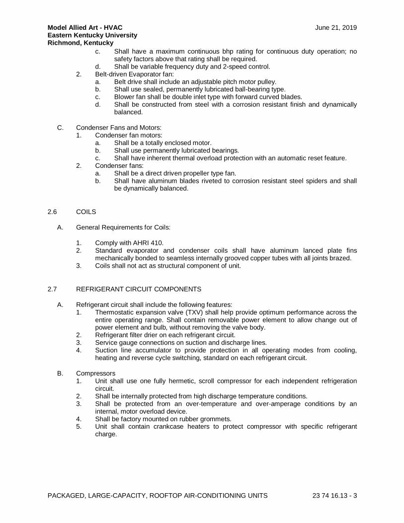
c. Shall have a maximum continuous bhp rating for continuous duty operation; nosafety factors above that rating shall be required.
d. Shall be variable frequency duty and 2-speed control.2. Belt-driven Evaporator fan:
a. Belt drive shall include an adjustable pitch motor pulley.b. Shall use sealed, permanently lubricated ball-bearing type.c. Blower fan shall be double inlet type with forward curved blades.d. Shall be constructed from steel with a corrosion resistant finish and dynamically
balanced.
C. Condenser Fans and Motors:1. Condenser fan motors:
a. Shall be a totally enclosed motor.b. Shall use permanently lubricated bearings.c. Shall have inherent thermal overload protection with an automatic reset feature.
2. Condenser fans:a. Shall be a direct driven propeller type fan.b. Shall have aluminum blades riveted to corrosion resistant steel spiders and shall
be dynamically balanced.
2.6 COILS
A. General Requirements for Coils:
1. Comply with AHRI 410.2. Standard evaporator and condenser coils shall have aluminum lanced plate fins
mechanically bonded to seamless internally grooved copper tubes with all joints brazed.3. Coils shall not act as structural component of unit.
2.7 REFRIGERANT CIRCUIT COMPONENTS
A. Refrigerant circuit shall include the following features:1. Thermostatic expansion valve (TXV) shall help provide optimum performance across the
entire operating range. Shall contain removable power element to allow change out ofpower element and bulb, without removing the valve body.
2. Refrigerant filter drier on each refrigerant circuit.3. Service gauge connections on suction and discharge lines.4. Suction line accumulator to provide protection in all operating modes from cooling,
heating and reverse cycle switching, standard on each refrigerant circuit.
B. Compressors1. Unit shall use one fully hermetic, scroll compressor for each independent refrigeration
circuit.2. Shall be internally protected from high discharge temperature conditions.3. Shall be protected from an over-temperature and over-amperage conditions by an
internal, motor overload device.4. Shall be factory mounted on rubber grommets.5. Unit shall contain crankcase heaters to protect compressor with specific refrigerant
charge.
Model Allied Art - HVAC June 21, 2019Eastern Kentucky UniversityRichmond, Kentucky
PACKAGED, LARGE-CAPACITY, ROOFTOP AIR-CONDITIONING UNITS 23 74 16.13 - 4
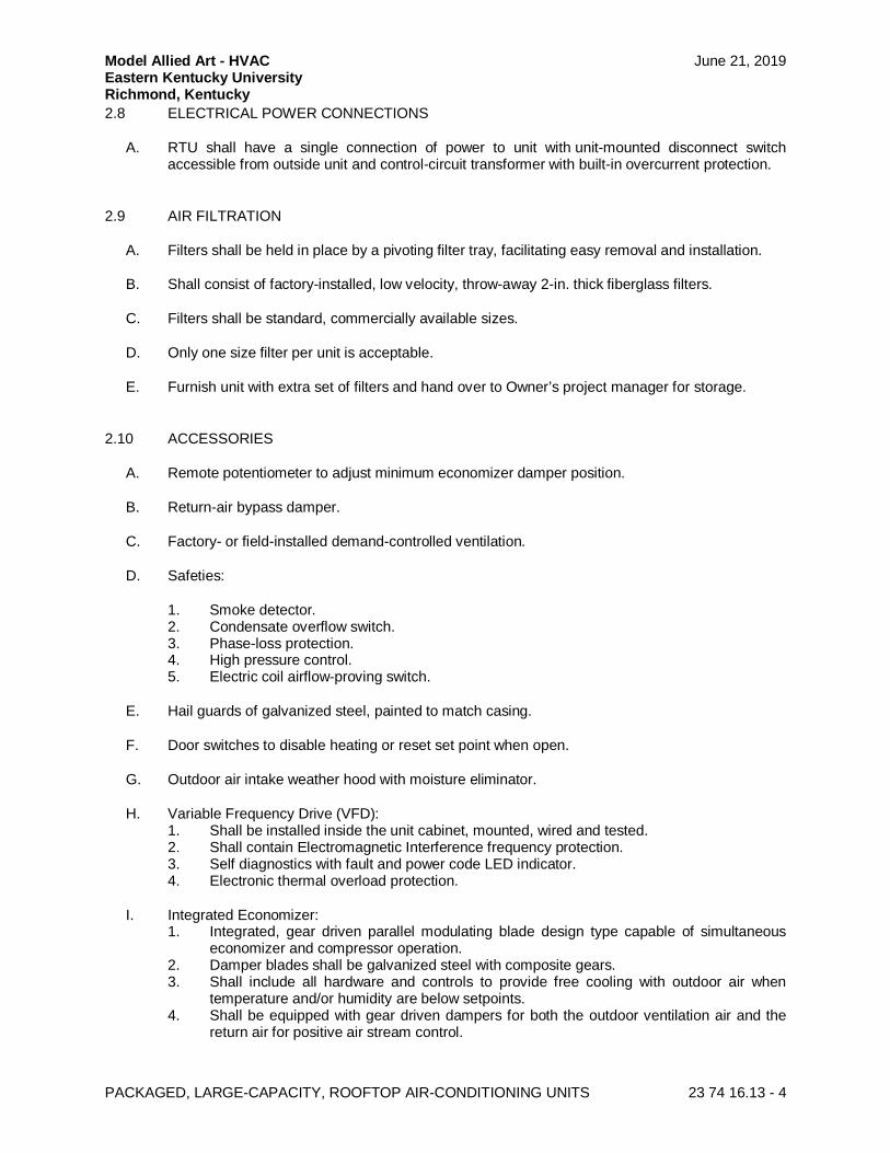
2.8 ELECTRICAL POWER CONNECTIONS
A. RTU shall have a single connection of power to unit with unit-mounted disconnect switchaccessible from outside unit and control-circuit transformer with built-in overcurrent protection.
2.9 AIR FILTRATION
A. Filters shall be held in place by a pivoting filter tray, facilitating easy removal and installation.
B. Shall consist of factory-installed, low velocity, throw-away 2-in. thick fiberglass filters.
C. Filters shall be standard, commercially available sizes.
D. Only one size filter per unit is acceptable.
E. Furnish unit with extra set of filters and hand over to Owner’s project manager for storage.
2.10 ACCESSORIES
A. Remote potentiometer to adjust minimum economizer damper position.
B. Return-air bypass damper.
C. Factory- or field-installed demand-controlled ventilation.
D. Safeties:
1. Smoke detector.2. Condensate overflow switch.3. Phase-loss protection.4. High pressure control.5. Electric coil airflow-proving switch.
E. Hail guards of galvanized steel, painted to match casing.
F. Door switches to disable heating or reset set point when open.
G. Outdoor air intake weather hood with moisture eliminator.
H. Variable Frequency Drive (VFD):1. Shall be installed inside the unit cabinet, mounted, wired and tested.2. Shall contain Electromagnetic Interference frequency protection.3. Self diagnostics with fault and power code LED indicator.4. Electronic thermal overload protection.
I. Integrated Economizer:1. Integrated, gear driven parallel modulating blade design type capable of simultaneous
economizer and compressor operation.2. Damper blades shall be galvanized steel with composite gears.3. Shall include all hardware and controls to provide free cooling with outdoor air when
temperature and/or humidity are below setpoints.4. Shall be equipped with gear driven dampers for both the outdoor ventilation air and the
return air for positive air stream control.
Model Allied Art - HVAC June 21, 2019Eastern Kentucky UniversityRichmond, Kentucky
PACKAGED, LARGE-CAPACITY, ROOFTOP AIR-CONDITIONING UNITS 23 74 16.13 - 5
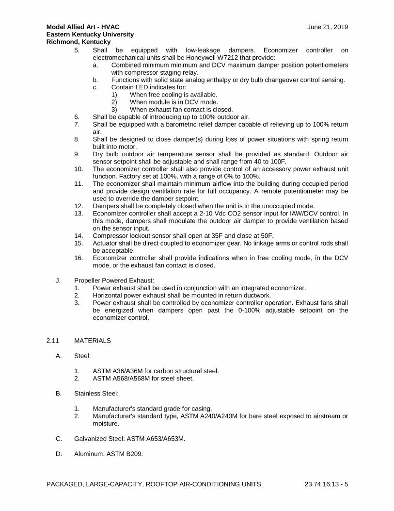
5. Shall be equipped with low-leakage dampers. Economizer controller onelectromechanical units shall be Honeywell W7212 that provide:a. Combined minimum minimum and DCV maximum damper position potentiometers
with compressor staging relay.b. Functions with solid state analog enthalpy or dry bulb changeover control sensing.c. Contain LED indicates for:
1) When free cooling is available.2) When module is in DCV mode.3) When exhaust fan contact is closed.
6. Shall be capable of introducing up to 100% outdoor air.7. Shall be equipped with a barometric relief damper capable of relieving up to 100% return
air.8. Shall be designed to close damper(s) during loss of power situations with spring return
built into motor.9. Dry bulb outdoor air temperature sensor shall be provided as standard. Outdoor air
sensor setpoint shall be adjustable and shall range from 40 to 100F.10. The economizer controller shall also provide control of an accessory power exhaust unit
function. Factory set at 100%, with a range of 0% to 100%.11. The economizer shall maintain minimum airflow into the building during occupied period
and provide design ventilation rate for full occupancy. A remote potentiometer may beused to override the damper setpoint.
12. Dampers shall be completely closed when the unit is in the unoccupied mode.13. Economizer controller shall accept a 2-10 Vdc CO2 sensor input for IAW/DCV control. In
this mode, dampers shall modulate the outdoor air damper to provide ventilation basedon the sensor input.
14. Compressor lockout sensor shall open at 35F and close at 50F.15. Actuator shall be direct coupled to economizer gear. No linkage arms or control rods shall
be acceptable.16. Economizer controller shall provide indications when in free cooling mode, in the DCV
mode, or the exhaust fan contact is closed.
J. Propeller Powered Exhaust:1. Power exhaust shall be used in conjunction with an integrated economizer.2. Horizontal power exhaust shall be mounted in return ductwork.3. Power exhaust shall be controlled by economizer controller operation. Exhaust fans shall
be energized when dampers open past the 0-100% adjustable setpoint on theeconomizer control.
2.11 MATERIALS
A. Steel:
1. ASTM A36/A36M for carbon structural steel.2. ASTM A568/A568M for steel sheet.
B. Stainless Steel:
1. Manufacturer's standard grade for casing.2. Manufacturer's standard type, ASTM A240/A240M for bare steel exposed to airstream or
moisture.
C. Galvanized Steel: ASTM A653/A653M.
D. Aluminum: ASTM B209.
Model Allied Art - HVAC June 21, 2019Eastern Kentucky UniversityRichmond, Kentucky
PACKAGED, LARGE-CAPACITY, ROOFTOP AIR-CONDITIONING UNITS 23 74 16.13 - 6
E. Comply with Section 23 05 46 "Coatings for HVAC" for corrosion-resistant coating.
F. Corrosion-Resistant Coating: Coat with a corrosion-resistant coating capable of withstanding a500-hour salt-spray test according to ASTM B117.
2.12 SOURCE QUALITY CONTROL
A. AHRI Compliance:
1. Comply with AHRI 340/360 for testing and rating energy efficiencies for RTUs.2. Comply with AHRI 210/240 for testing and rating energy efficiencies for RTUs3. Comply with AHRI 270 for testing and rating sound performance for RTUs.4. Comply with AHRI 1060 for testing and rating performance for air-to-air exchanger.
PART 3 - EXECUTION
3.1 INSTALLATION
A. Examine roughing-in for RTUs to verify actual locations of piping and duct connections beforeequipment installation.
B. Unit Support: Install unit level on grade. Coordinate wall penetrations and flashing with wallconstruction. Secure RTUs to structural support with anchor bolts.
3.2 PIPING CONNECTIONS
A. Piping installation requirements are specified in other Sections. Drawings indicate generalarrangement of piping, fittings, and specialties.
B. Where installing piping adjacent to RTU, allow space for service and maintenance.
C. Connect piping to unit mounted on vibration isolators with flexible connectors.
3.3 DUCT CONNECTIONS
A. Comply with duct installation requirements specified in other HVAC Sections. Drawings indicatethe general arrangement of ducts. The following are specific connection requirements:
1. Install ducts to termination at top of roof curb.2. Connect supply and return ducts to RTUs with flexible duct connectors specified in
Section 23 33 00 "Air Duct Accessories."
3.4 ELECTRICAL CONNECTIONS
A. Connect electrical wiring according to Section 26 05 19 "Low-Voltage Electrical PowerConductors and Cables."
B. Ground equipment according to Section 26 05 26 "Grounding and Bonding for ElectricalSystems."
Model Allied Art - HVAC June 21, 2019Eastern Kentucky UniversityRichmond, Kentucky
PACKAGED, LARGE-CAPACITY, ROOFTOP AIR-CONDITIONING UNITS 23 74 16.13 - 7
C. Install electrical devices furnished by manufacturer, but not factory mounted, according toNFPA 70 and NECA 1.
D. Install nameplate for each electrical connection, indicating electrical equipment designation andcircuit number feeding connection.
1. Nameplate shall be laminated acrylic or melamine plastic signs as specified in Section26 05 53 "Identification for Electrical Systems."
2. Nameplate shall be laminated acrylic or melamine plastic signs as layers of black withengraved white letters at least 1/2 inch high.
3. Locate nameplate where easily visible.
3.5 CONTROL CONNECTIONS
A. Install control and electrical power wiring to field-mounted control devices.
B. Connect control wiring according to Section 26 05 23 "Control-Voltage Electrical Power Cables."
3.6 FIELD QUALITY CONTROL
A. Perform the following tests and inspections with the assistance of a factory-authorized servicerepresentative:
1. After installing RTUs and after electrical circuitry has been energized, test units forcompliance with requirements.
2. Inspect for and remove shipping bolts, blocks, and tie-down straps.3. Operational Test: After electrical circuitry has been energized, start units to confirm
proper motor rotation and unit operation.4. Test and adjust controls and safeties. Replace damaged and malfunctioning controls and
equipment.
B. RTU will be considered defective if it does not pass tests and inspections.
C. Prepare test and inspection reports.
3.7 DEMONSTRATION
A. Train Owner's maintenance personnel to adjust, operate, and maintain RTUs.
END OF SECTION 23 74 16.13
Model Allied Art - HVAC June 21, 2019Eastern Kentucky UniversityRichmond, Kentucky
SPLIT-SYSTEM AIR-CONDITIONERS 23 81 26 - 1
SECTION 23 81 26 - SPLIT-SYSTEM AIR-CONDITIONERS
PART 1 - GENERAL
1.1 SUMMARY
A. Section includes split-system air-conditioning and heat-pump units consisting of separateevaporator-fan and compressor-condenser components.
1.2 ACTION SUBMITTALS
A. Product Data: For each type of product indicated.
1.3 INFORMATIONAL SUBMITTALS
A. Warranty: Sample of special warranty.
1.4 CLOSEOUT SUBMITTALS
A. Operation and maintenance data.
1.5 QUALITY ASSURANCE
A. Electrical Components, Devices, and Accessories: Listed and labeled as defined in NFPA 70,by a qualified testing agency, and marked for intended location and application.
1.6 WARRANTY
A. Special Warranty: Manufacturer's standard form in which manufacturer agrees to repair orreplace components of split-system air-conditioning units that fail in materials or workmanshipwithin specified warranty period.
1. Warranty Period:
a. For Compressor: Five year(s) from date of Substantial Completion.b. For Parts: One year(s) from date of Substantial Completion.c. For Labor: One year(s) from date of Substantial Completion.
PART 2 - PRODUCTS
2.1 MANUFACTURERS
A. Manufacturers: Subject to compliance with requirements, available manufacturers offeringproducts that may be incorporated into the Work include, but are not limited to the following:
Model Allied Art - HVAC June 21, 2019Eastern Kentucky UniversityRichmond, Kentucky
SPLIT-SYSTEM AIR-CONDITIONERS 23 81 26 - 2
1. Carrier Corporation.
2. Lennox Industries, Inc.
3. Goodman Manufacturing.
2.2 INDOOR UNITS (5 TONS OR LESS)
A. Concealed Evaporator-Fan Components:
1. Chassis: Galvanized steel with flanged edges, removable panels for servicing, andinsulation on back of panel.
2. Insulation: Faced, glass-fiber duct liner.3. Refrigerant Coil: Copper tube, with mechanically bonded aluminum fins and thermal-
expansion valve. Comply with ARI 206/110.4. Electric Coil: Helical, nickel-chrome, resistance-wire heating elements; with refractory
ceramic support bushings, automatic-reset thermal cutout, built-in magnetic contactors,manual-reset thermal cutout, airflow proving device, and one-time fuses in terminal boxfor overcurrent protection.
5. Fan: Forward-curved, double-width wheel of galvanized steel; directly connected tomotor.
6. Fan Motors:a. Multitapped, multispeed with internal thermal protection and permanent lubrication.b. Wiring Terminations: Connect motor to chassis wiring with plug connection.
7. Airstream Surfaces: Surfaces in contact with the airstream shall comply withrequirements in ASHRAE 62.1.
8. Filters: Permanent, cleanable.9. Condensate Drain Pans:
a. Fabricated with one percent slope in at least two planes to collect condensate fromcooling coils (including coil piping connections, coil headers, and return bends) andhumidifiers, and to direct water toward drain connection.1) Depth: A minimum of 2 inches deep.
b. Single-wall, galvanized-steel sheet.c. Drain Connection: Located at lowest point of pan and sized to prevent overflow.
Terminate with threaded nipple on one end of pan.
1) Minimum Connection Size: NPS 1.
d. Pan-Top Surface Coating: Asphaltic waterproofing compound.e. Units with stacked coils shall have an intermediate drain pan to collect condensate
from top coil.
2.3 OUTDOOR UNITS (5 TONS OR LESS)
A. Air-Cooled, Compressor-Condenser Components:
1. Casing: Steel, finished with baked enamel in color selected by Architect, with removablepanels for access to controls, weep holes for water drainage, and mounting holes inbase. Provide brass service valves, fittings, and gage ports on exterior of casing.
Model Allied Art - HVAC June 21, 2019Eastern Kentucky UniversityRichmond, Kentucky
SPLIT-SYSTEM AIR-CONDITIONERS 23 81 26 - 3
2. Compressor: Hermetically sealed with crankcase heater and mounted on vibrationisolation device. Compressor motor shall have thermal- and current-sensitive overloaddevices, start capacitor, relay, and contactor.
a. Compressor Type: Scroll.b. Refrigerant: R-410A.c. Refrigerant Coil: Copper tube, with mechanically bonded aluminum fins and liquid
subcooler. Comply with ARI 206/110.
3. Heat-Pump Components: Reversing valve and low-temperature-air cutoff thermostat.4. Fan: Aluminum-propeller type, directly connected to motor.5. Motor: Permanently lubricated, with integral thermal-overload protection.6. Low Ambient Kit: Permits operation down to 30 deg F.7. Mounting Base: Polyethylene.
2.4 ACCESSORIES
A. Thermostat: Low voltage with subbase to control compressor and evaporator fan.
B. Automatic-reset timer to prevent rapid cycling of compressor.
C. Refrigerant Line Kits: Comply with Section 232300 “Refrigerant Piping.”
D. Drain Hose: For condensate.
2.5 CAPACITIES AND CHARACTERISTICS
A. Refer to Schedule on Drawings.
PART 3 - EXECUTION
3.1 INSTALLATION
A. Install units level and plumb.
B. Install evaporator-fan components using manufacturer's standard mounting devices securelyfastened to building structure.
C. Install and connect precharged refrigerant tubing to component's quick-connect fittings. Installtubing to allow access to unit.
3.2 CONNECTIONS
A. Piping installation requirements are specified in other Sections. Drawings indicate generalarrangement of piping, fittings, and specialties.
B. Where piping is installed adjacent to unit, allow space for service and maintenance of unit.
C. Duct Connections: Duct installation requirements are specified in Section 23 31 13 "MetalDucts." Drawings indicate the general arrangement of ducts. Connect supply and return ducts to
Model Allied Art - HVAC June 21, 2019Eastern Kentucky UniversityRichmond, Kentucky
SPLIT-SYSTEM AIR-CONDITIONERS 23 81 26 - 4
split-system air-conditioning units with flexible duct connectors. Flexible duct connectors arespecified in Section 23 33 00 "Air Duct Accessories."
3.3 FIELD QUALITY CONTROL
A. Perform tests and inspections.
1. Manufacturer's Field Service: Engage a factory-authorized service representative toinspect components, assemblies, and equipment installations, including connections, andto assist in testing.
B. Tests and Inspections:
1. Leak Test: After installation, charge system and test for leaks. Repair leaks and retestuntil no leaks exist.
2. Operational Test: After electrical circuitry has been energized, start units to confirmproper motor rotation and unit operation.
3. Test and adjust controls and safeties. Replace damaged and malfunctioning controls andequipment.
C. Remove and replace malfunctioning units and retest as specified above.
D. Prepare test and inspection reports.
3.4 DEMONSTRATION
A. Train Owner's maintenance personnel to adjust, operate, and maintain units.
END OF SECTION 23 81 26
Related Documents