Series ZYY/ZYX Ejector Valve Unit Nozzle diameter: ø0.7, ø1.0 Type S: Standard type L : Large flow type Series ZYY3000 (Solenoid valve: SY3000) Series ZYX3000 (Solenoid valve: SX3000) Ejectors and solenoid valves can be mounted on the same manifold. Centralized wiring of ejector (ZYX3000: Individual pressure switch not included) 1081 ZA ZX ZR ZM ZMA ZQ ZH ZU ZL ZY ZF ZP SP ZCUK AMJ AMV AEP HEP Related Equipment

Welcome message from author
This document is posted to help you gain knowledge. Please leave a comment to let me know what you think about it! Share it to your friends and learn new things together.
Transcript

Series ZYY/ZYXEjector Valve Unit
Nozzle diameter: ø0.7, ø1.0Type S: Standard type
L: Large flow type
Series ZYY3000(Solenoid valve: SY3000)
Series ZYX3000(Solenoid valve: SX3000)
Ejectors and solenoid valves can be mounted on the same manifold.Centralized wiring of ejector
(ZYX3000: Individual pressure switch not included)
1081
ZA
ZX
ZR
ZM
ZMA
ZQ
ZH
ZU
ZL
ZY�
ZF�
ZP�
SP
ZCUK
AMJ
AMV
AEP
HEPRelatedEquipment
P1067-P1100-E.qxd 08.9.30 3:04 PM Page 1081

How to Order Ejector Valves for ZYY3000
Without light/surge voltage suppressorWith surge voltage suppressorWith light/surge voltage suppressorWith surge voltage suppressor (Non-polar type)With light/surge voltage suppressor (Non-polar type)
NilSZRU
Light/Surge voltage suppressor
NPN open collector, single outputAnalog, no output, 3 turn setting
NPN open collector, single outputAnalog, no output, 200 degree setting
NPN open collector, double outputAnalog, no output, 3 turn setting
NPN open collector, double outputAnalog, no output, 200 degree setting
NPN open collector, single outputAnalog, with output, 3 turn setting
NPN open collector, single outputAnalog, with output, 200 degree setting
PNP open collector, single outputAnalog, no output, 200 degree setting
14
15
16
17
18
19
55
Output specifications(Vacuum switch)
10Y3ZY
Rated voltage
Y3SeriesSY3000
56VSR
24 VDC12 VDC6 VDC5 VDC3 VDC
Wiring specifications(Vacuum switch)
S 15
GHL
LNLOM
MNMO
Electrical entry
Lead wire length 300 mmLead wire length 600 mmWith lead wires (Length 300 mm)Without lead wires Without connectorWith lead wires (Length 300 mm)Without lead wires Without connector
Grommet
L plugconnector
M plugconnector
Nozzle diameter
Manual override
NoneWith vacuum switch
NilE
Vacuum switch
With manifold blockNone
NilMN
Manifold block
Connector box typeLOU
Lead wire/Voltage suppressor specifications
NoneWith silencer
Nil1
Silencer
–84 kPa–53 kPa
SL
0.7 mm1.0 mm
0710
Non-locking push typePush-turn locking slotted typePush-turn locking lever type
NilDE
Max. vacuum pressure
L Z5 LOU
For electrical entry types G, H, L, M
1234
100 VAC200 VAC
110 VAC [115VAC]220 VAC [230VAC]
DC specifications
AC specifications (50/60 Hz)
24, 12, 6, 5, 3 VDC/100, 110, 200, 220 VAC
NilLC
CLCN
Lead wire length 0.6 mLead wire length 3 mLead wire length 0.6 mLead wire length 3 mConnector type
Grommettype
Connectortype
Note) The connector box type and serial transmission type are only available with 5 (24 VDC).
Types LN and MN are equipped with sockets (2 pcs.).Not compatible with the FU electrical en-try which is used on Series SY3000 plug-in type manifolds (45F, 45P�, 45T, 45T1, 45S�, 45S1�, 45S2�, 45S3�).
Note 1)
Note 2)
Types R and U are DC only.Since surge voltage is prevented with a rectifier in the case of AC, there is no type “S”.
Note 1)Note 2)
1082
Ejector Valve Unit
Series ZYY/ZYX
P1067-P1100-E.qxd 08.9.30 3:04 PM Page 1082

M
Without light/surge voltage suppressorWith surge voltage suppressorWith light/surge voltage suppressor
NilSZ
Light/Surge voltage suppressor
NPN open collector, single outputAnalog, no output, 3 turn setting
NPN open collector, single outputAnalog, no output, 200 degree setting
NPN open collector, double outputAnalog, no output, 3 turn setting
NPN open collector, double outputAnalog, no output, 200 degree setting
NPN open collector, single outputAnalog, with output, 3 turn setting
NPN open collector, single outputAnalog, with output, 200 degree setting
PNP open collector, single outputAnalog, with output, 200 degree setting
14
15
16
17
18
19
55
Output specifications(Vacuum switch)
10X3ZY
Rated voltage
X3Series SX3000
NilN
Common specificationsPositive commonNegative common
56VSR
24 VDC12 VDC6 VDC5 VDC3 VDC
Wiring specifications(Vacuum switch)
S 15
GHL
LNLOM
MNMO
Electrical entryLead wire length 300 mmLead wire length 600 mmWith lead wires (Length 300 mm)Without lead wiresWithout connectorWith lead wires (Length 300 mm)Without lead wires Without connector
Grommet
L plugconnector
M plugconnector
Nozzle diameter
Manual override
NoneWith silencer
NilE
Vacuum switch
Plug-in typeNon plug-in type
NilF
Plug-in/Non plug-in type
With manifold blockNone
NilMN
Manifold block
NoneWith vacuum switch
Nil1
Silencer
–84 kPa–53 kPa
SL
0.7 mm1.0 mm
0710
Non-locking push typePush-turn locking slotted type
NilD
Max. vacuum pressure
5 M Z
For electrical entry types G, H, L, M
DC specifications
NilLC
CLCN
Lead wire length 0.6 mLead wire length 3 mLead wire length 0.6 mLead wire length 3 mConnector type
Grommettype
Connectortype
Plug-in typeSerial transmission type
LOZ
Lead wire/Voltage suppressor specifications
How to Order Ejector Valves for ZYX3000
LOZ
Note 1) The serial transmis-sion type is 5 (24 VDC) only.
Note 2) V, S and R specifica-tions are 45T, 45T1.
Note 1) The symbol is “Nil” for the single grommet type and when not equipped with light/surge voltage suppressor.
Note 2) Match with the common specification of the manifold.
Note) For types LN and MN, the single solenoid has 2 sockets and the double solenoid has 3 sock-ets.
1083
Ejector Valve Unit Series ZYY/ZYX
ZA
ZX
ZR
ZM
ZMA
ZQ
ZH
ZU
ZL
ZY�
ZF�
ZP�
SP
ZCUK
AMJ
AMV
AEP
HEPRelatedEquipment
P1067-P1100-E.qxd 08.9.30 3:04 PM Page 1083

For solenoid valve and ejector valve combination
For ejector valves only(Without solenoid valves: individual wiring type is compliant only.)
Y 3X 3SS5 45
Y 3X 3ZZY
Change to ZZYEjector valvenumbers
45 J 1 U
With ejector
Number of ejectors1 to 10
Ejector mounting position
Ejector valveZYY35LZ-10S-E15C
Double solenoid (24 VDC)SY3240-5LZ
Single solenoid (24 VDC)SY3140-5LZ
Blanking plate assemblySX3000-75-1A
Cylinder port sizeC6 : With ø6 One-touch fittingManifold base (4 stations)ZZYY3-45-04D-C6-J1U
JZZY 1 U
With ejector
Number of ejectors1 to 10
Example) ZYY-J3U
∗ ZYY35MZ-10S1-E15C-F∗ ZYY35MZ-10S1-F
2SETS1SET
1SET
[Example: When individual wiring type model 45 for SY3000 is selected]
ZZY Y3-45-04D-C6-SY3000 manifold model Ejector valve
number
J1U 1SET
∗ SX3000-75-1A∗ SY3140-5LZ∗ SY3240-5LZ∗ ZYY35LZ-10S-E15C
1SET1SET1SET1SET
UD
U sideD side
Note 1)
However, (optional DIN rail) is a special order specification.
SY3000/SX3000Same as ordering manifold.
Enter the following together with the manifold number:
1. Part no. of solenoid for SY3000/SX30002. Part no. of ejector valve for ZYY3000/ZYX3000.
∗ is the symbol for a built-in assembly. Add the ∗ symbol at the beginning of part numbers for solenoid valves, etc. to be mounted, and enter these together in order from the D side.
U side
Stations····3 2 1
D side
Note 1) The combined total of solenoid valve and ejector valve stations is a maximum of 20 stations.(Example: When there are 12 solenoid valve sta-tions, there are 8 ejector stations.)
1084
Series ZYY/ZYX
How to Order Manifold Valves for ZYY3000/ZYX3000 (Split Base/DIN Rail Mounting)
P1067-P1100-E.qxd 08.9.30 3:05 PM Page 1084

Ejector Valve Specifications
Supply/Release Valve Specifications
ZY�3���–07S
0.7 1.0
0.6 MPa
0.45 MPa
5 to 50°C
ZY�3���–07L ZY�3���–10S ZY�3���–10L
11
–84
18
–53
22
–84
32
–53
Valve type
Type of actuation
Fluid
Operating pressure range
Ambient and fluid temperature
Allowable voltage fluctuation
Electrical entry
Power consumption
Effective area (Cv factor)
Pilot type 3 position 3 port solenoid valve
Closed center
Air
0.2 to 0.6 MPa
5 to 50°C
–10 to +10%
Grommet : G, H L plug connector: L, LN, LO
M plug connector: M, MN, MO
0.5 W (With indicator light: 0.6 W): Series ZYY3000
0.6 W (With indicator light: 0.65 W): Series ZYX3000
4.68 mm2 (0.26)
ZYY3000 Series
ZYX3000 Series
Ejector valve model
Nozzle diameter (mm)
Max. suction flow rate N (l/min (ANR))
Max. vacuum pressure (kPa)
Maximum operating pressure
Standard supply pressure
Operating temperature range
Series SY3000/SX3000 in manifold/split base combinations DIN rail mount type can be mounted
Compact (integrated construction of ejector and valve)Copper-free and fluorine-free measures implemented
1085
Ejector Valve Unit Series ZYY/ZYX
ZA
ZX
ZR
ZM
ZMA
ZQ
ZH
ZU
ZL
ZY�
ZF�
ZP�
SP
ZCUK
AMJ
AMV
AEP
HEPRelatedEquipment
P1067-P1100-E.qxd 08.9.30 3:05 PM Page 1085

Sensor type
Set pressure range
Hysteresis
Repeatability
Temperature characteristics
Operating voltage
ZSE1– 00 –14�–X129 (–X130)
ZSE1– 00 –15�–X129 (–X130)
ZSE1– 00 –16�–X129 (–X130)
ZSE1– 00 –17�–X129 (–X130)
ZSE1– 00 –18�–X129 (–X130)
ZSE1– 00 –19�–X129 (–X130)
ZSE1– 00 –55�–X129 (–X130)
Diffusion type semiconductor pressure sensor
0 to –101 kPa
±1% full span or less
±3% full span or less
12 to 24 VDC (Ripple ±10% or less)
PNP opencollector
Max. 80 mANPN open collector 30 V Max. 80 mA
Lights up when ON (Red) Lights up when ON (Red)Lights up when ON
(OUT1: Red, OUT2: Green)
None
1 point
3 turns 200 degrees 3 turns 200 degrees 3 turns 200 degrees 200 degrees
1 point2 point
None1 to 5V
1 to –10% of set pressure (Adjustable)
17 mA or less (When 24 VDC is ON) 25 mA or less (When 24 VDC is ON)
0.2 MPa
17 mA or less (When 24 VDC is ON)
1 to –10% of set pressure (Adjustable)3% full span or less (Fixed)
Model
ON-OFF output
Operationindicator light
Setting trimmerrotation angle
Analog output
Setting points
Current consumption
Max. operating pressure
15 130ZSE1 00
14
15
16
17
18
19
55
Output specifications
Wiring specifications
Compatible model
NPN open collector, single outputAnalog, no output, 3 turn setting
NPN open collector, single outputAnalog, no output, 200 degree setting
NPN open collector, double outputAnalog, no output, 3 turn setting
NPN open collector, double outputAnalog, no output, 200 degree setting
NPN open collector, single outputAnalog, with output, 3 turn setting
NPN open collector, single outputAnalog, with output, 200 degree setting
PNP open collector, single outputAnalog, no output, 200 degree setting
Grommet type
Connector type
Lead wire length 0.6 m
Lead wire length 3 m
Lead wire length 0.6 m
Lead wire length 3 m
Without connector
129
130
Nil
L
C
CL
CN
For Series ZYX3000
For Series ZYY3000
X
Nil
30
50
0.6 m
3 m
5 m
With connector/How to Order
ZS-20-AZS-20-5A-
Lead wire length
Electronic Vacuum Pressure Switch Specifications
How to Order Electronic Vacuum Pressure Switch
Note 1) When using an ejector, there is no problem if pressure of 0.5 MPa is applied for 1 second or less.Note 2) X129 is for Series ZYX3000 and X130 is for Series ZYY3000.
�Without lead wires (1 connector and 4 sockets)�With lead wires
Example) ZSE1-00-15CN-X129ZS-20-5A-50
1 pc.
1 pc.
Note) When ordering a switch with 5 m lead wires, enter the part num-bers for both a switch without connector and lead wires with con-nector.
1086
Series ZYY/ZYX
P1067-P1100-E.qxd 08.9.30 3:05 PM Page 1086
How to Set the Pressure How to Use the Connector1. Attaching and detaching connectors
Internal Circuit and Wiring Example
Hysteresis
ZSE1-��-14/-15/-18/-19
ZSE1-��-16/-17
2. Crimping of lead wire and socket
3. Attaching and detaching of socket to connector with lead wire
ZSE1- -14, -15
ZSE1- -16, -17
ZSE1- -18, -19
ZSE1- -55
Mai
n ci
rcui
t of s
witc
h
Black
Black
Blue DC (–)
Blue DC (–)
12 to 24 VDCLoad30V, 80mA
OUT
(OUT1)
(OUT1)
Analog output
(OUT1)
Mai
n ci
rcui
t of s
witc
h
White 12 to 24 VDC
30V, 80mA
Mai
n ci
rcui
t of s
witc
h
Mai
n ci
rcui
t of s
witc
h
Brown DC (+)
White
Blue DC (–)
12 to 24 VDC30V, 80mA
Black
Brown DC (+)
Black
Blue DC (–)
12 to 24 VDC80mA
Set pressure
High
vacu
um
Hyste
resis ON
OFF
Connector
Lead wire
Socket
Hook
Lead wireSocket
Covering retainerCore wire crimping area
Hook Covering
Core wire
High p
ressur
e
Set pressure
Supply pressure
Atmosphericpressure
0
Hig
h va
cuum
30V, 80mA(OUT2)
Hysteresis setting trimmer
Pressure setting trimmer
SET
HYSIndicator light
Indicator light SET2
SET1
Pressure setting trimmer 1
Pressure setting trimmer 2
Lead wire
Socket
ConnectorDC polarity indication
Lever
Hook
Hook
Lead wireSocket
ConnectorDC polarity indicationLeverPinSlotHousing
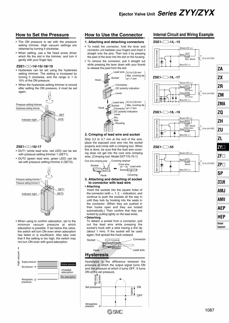
• The ON pressure is set with the pressure setting trimmer. High vacuum settings are obtained by turning it clockwise.
• When setting, use a flat head screw driver which fits the slot in the trimmer, and turn it gently with your finger tips.
• Hysteresis can be set using the hysteresis setting trimmer. The setting is increased by turning it clockwise, and the range is 1 to 10% of the ON pressure.
• When the hysteresis setting trimmer is moved after setting the ON pressure, it must be set again.
• OUT1 (white lead wire, red LED) can be set with pressure setting trimmer 1 (SET1).
• OUT2 (green lead wire, green LED) can be set with pressure setting trimmer 2 (SET2).
• When using to confirm adsorption, set to the minimum vacuum pressure at which adsorption is possible. If set below this valve, the switch will turn ON even when adsorption has failed or is insufficient. Also take note that if the setting is too high, the switch may not turn ON even with good adsorption.
Unstableadsorption
No adsorption
Reliable adsorption
• To install the connector, hold the lever and connector unit between your fingers and insert it straight onto the pins. Then lock it by pressing the pawl of the lever into the slot on the housing.
• To remove the connector, pull it straight out while pressing the lever down with your thumb to release the pawl from the slot.
0.2 to 0.33 mm2
Max. covering dia.ø1.7 mm
0.2 to 0.33 mm2
Max. covering dia.ø1.7 mm
Strip 3.2 to 3.7 mm at the end of the wire, place the exposed core wire into the socket properly and crimp with a crimping tool. When this is done, be sure that the lead wire cover-ing does not get into the core wire crimping area. (Crimping tool: Model DXT170-75-1)
• AttachingInsert the sockets into the square holes of the connector (with +, 1, 2, – indication), and continue to push the sockets all the way in until they lock by hooking into the seats in the connector. (When they are pushed in their hooks open and they are locked automatically.) Then confirm that they are locked by pulling lightly on the lead wires.
• DetachingTo detach a socket from a connector, pull out the lead wire while pressing the socket’s hook with a stick having a thin tip (about 1 mm). If the socket will be used again, first spread the hook outward.
Hysteresis is the difference between the pressure at which the output signal turns ON and the pressure at which it turns OFF. It turns ON at the set pressure.
Atmosphericpressure 0
Brown DC (+)
Brown DC (+)
–
+
Load
Load
Load
Load
Load
–
+
–
+
–
+
1087
Ejector Valve Unit Series ZYY/ZYX
ZA
ZX
ZR
ZM
ZMA
ZQ
ZH
ZU
ZL
ZY�
ZF�
ZP�
SP
ZCUK
AMJ
AMV
AEP
HEPRelatedEquipment
P1067-P1100-E.qxd 08.9.30 3:05 PM Page 1087

Construction
ZYY3000
Section A-A' (Ejector)
Section B-B' (Solenoid valve)
B
A
B
A
Component PartsNo.
1
2
3
4
5
6
7
8
Description Material
Resin
Zinc die-casted
Resin
Aluminum alloy
Aluminum alloy
Stainless steel
Aluminum alloy
Resin
Note
Urban white
Urban white
Urban white
Manifold block
Body
Silencer cover
Nozzle
Diffuser
Needle
Spool
Piston
Replacement PartsNo.
9
10
11
12
13
Description Part no.
3 port solenoid valve
Vacuum switch
End plate assembly
Silencer
Non plug assembly
SY114-���ZSE1-00-���-X130
P44027A (Without a switch)
AN203-KM8
ZYY3000-NPA
1011
4 5
3
12
13
8 2 79
6
1
1088
Series ZYY/ZYX
P1067-P1100-E.qxd 08.9.30 3:05 PM Page 1088

Construction
ZYX3000
Section A-A' (Ejector)
Section B-B' (Solenoid valve)
B B
A
A
A B
B
Component PartsNo.
1
2
3
4
5
6
7
8
Description Material
Resin
Zinc die-casted
Resin
Aluminum alloy
Aluminum alloy
Stainless steel
Aluminum alloy
Resin
Note
Urban white
Urban white
Urban white
Manifold block
Body
Silencer cover
Nozzle
Diffuser
Needle
Spool
Piston
Replacement PartsNo.
9
10
11
12
Description Part no.
Vacuum switch
End plate assembly
Silencer
Plug assembly
ZSE1-00-���-X129
P440119A (Without a switch)
AN203-KM8
ZYY3000-PA
A
P1
EXH.
1089
Ejector Valve Unit Series ZYY/ZYX
910
4 5
3
11
12
2 7
8
6
1
ZA
ZX
ZR
ZM
ZMA
ZQ
ZH
ZU
ZL
ZY�
ZF�
ZP�
SP
ZCUK
AMJ
AMV
AEP
HEPRelatedEquipment
P1067-P1100-E.qxd 08.9.30 3:05 PM Page 1089

Exhaust Characteristics/Flow Characteristics
ZY �����-07SExhaust Characteristics Flow Characteristics Exhaust Characteristics Flow Characteristics
Exhaust Characteristics Flow Characteristics Exhaust Characteristics Flow Characteristics
The flow rate characteristics correspond to a supply pressure of 0.45 MPa.
Y3X3 ZY �����-07L
Y3X3
ZY �����-10SY3X3 ZY �����-10L
Y3X3
-100
-80
-60
-40
-20
0
50
40
30
20
10
0
0 0.1 0.2 0.3 0.4 0.5 0.6
-100
-80
-60
-40
-20
0
0 10 20
-100
-80
-60
-40
-20
0
50
40
30
20
10
0
0 0.1 0.2 0.3 0.4 0.5 0.6
-100
-80
-60
-40
-20
0
0 5 10 15 20 25
-100
-80
-60
-40
-20
0
60
40
20
0
0 0.1 0.2 0.3 0.4 0.5 0.6
Q1
P1
Qmax
Pmax
Suction flow rate
Vac
uum
pre
ssur
e
-100
-80
-60
-40
-20
0
0
-100
-80
-60
-40
-20
0
60
40
20
0
0 0.1 0.2 0.3 0.4 0.5 0.6
-100
-80
-60
-40
-20
0
0 10 20 30 40 505 10 15 20 25
How to Read Flow Characteristics Graph
Supply pressure (MPa) Suction flow rate (l/min(ANR))
Vac
uum
pre
ssur
e (k
Pa)
Vac
uum
pre
ssur
e (k
Pa)
Suc
tion
flow
rat
e ( l
/min
(AN
R))
Air
cons
umpt
ion
flow
rat
e (l
/min
(AN
R))
Supply pressure (MPa) Suction flow rate (l/min(ANR))
Vac
uum
pre
ssur
e (k
Pa)
Vac
uum
pre
ssur
e (k
Pa)
Suc
tion
flow
rat
e ( l
/min
(AN
R))
Air
cons
umpt
ion
flow
rat
e (l
/min
(AN
R))
Supply pressure (MPa) Suction flow rate (l/min(ANR))
Vac
uum
pre
ssur
e (k
Pa)
Vac
uum
pre
ssur
e (k
Pa)
Suc
tion
flow
rat
e ( l
/min
(AN
R))
Air
cons
umpt
ion
flow
rat
e (l
/min
(AN
R))
Vacuum pressure
Vacuum pressure
Vacuum pressure
Vacuum pressure
Air consumption Air consumption
Air consumption
Air consumption
Suction flow rate
Suction flow rate
Suction flow rate
Suction flow rate
The flow rate characteristics indicate the relationship between the vacuum pressure and the suction flow rate of the ejector, and show that when the suction flow rate changes the vacuum pressure also changes. In general, this indicates the relationship at the ejector,s standard operating pressure. In the graph, Pmax indicates the maximum vacuum pressure, and Qmax indicates the maximum suction flow rate. These are the values that are published as specifications in catalogs, etc. The methods for changing the vacuum pressure will be explained in order.1. If the ejector’s suction port is closed and sealed tight, the suction flow rate becomes “0”
and the vacuum pressure increases to the maximum (Pmax). 2. If the suction port is opened gradually and air is allowed to flow (the air leaks), the
inlet flow rate increases and the vacuum pressure decreases. (the condition of P1 and Q1)
3. If the suction port is opened completely, the suction flow rate increases to the maximum (Qmax), while the vacuum pressure then drops almost to “0” (atmospheric pressure).
In this way, when the suction flow rate changes the vacuum pressure also changes. In other words, when there is no leakage at the vacuum port (vacuum piping), the vacuum pressure increases to the maximum, but the vacuum pressure drops as the amount of leakage increases, and when the amount of leakage and the maximum suction flow rate become equal, the vacuum pressure decreases nearly to “0”. When adsorbing workpieces which are permeable or subject to leakage, etc., caution is required as the vacuum pressure will not be very high.
Supply pressure (MPa) Suction flow rate (l/min(ANR))
Vac
uum
pre
ssur
e (k
Pa)
Vac
uum
pre
ssur
e (k
Pa)
Suc
tion
flow
rat
e ( l
/min
(AN
R))
Air
cons
umpt
ion
flow
rat
e (l
/min
(AN
R))
1090
Series ZYY/ZYX
P1067-P1100-E.qxd 08.9.30 3:05 PM Page 1090
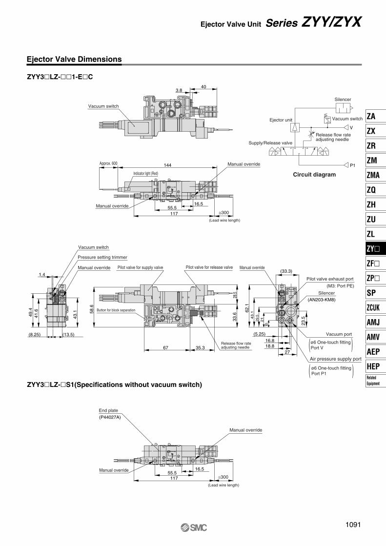
Vacuum switchEjector unit
V
P1
Release flow rateadjusting needle
Silencer
Supply/Release valve
Ejector Valve Dimensions
ZYY3�LZ-��1-E�C
ZYY3�LZ-�S1(Specifications without vacuum switch)
49.4
41.6
1.4
144
403.8
16.5
11755.5
16.5
11755.5
58.6
28.5
33.6
67 35.3
(13.5)(8.25)
43.1
(33.3)
62.1
43.1
23.529
.521
10
2718.816.8
(5.25)
Vacuum switch
Circuit diagram
Manual override
Manual override
Approx. 600
≅300
Indicator light (Red)
(Lead wire length)
Vacuum switch
Pressure setting trimmer
Manual override Pilot valve for supply valve
Button for block separation
Pilot valve for release valve
Release flow rateadjusting needle
Manual override
Pilot valve exhaust port
(M3: Port PE)
Silencer
(AN203-KM8)
Vacuum port
Air pressure supply port
End plate
(P44027A)
Manual override
Manual override
≅300
(Lead wire length)
ø6 One-touch fitting Port V (
(
(
(ø6 One-touch fitting Port P1
1091
Ejector Valve Unit Series ZYY/ZYX
ZA
ZX
ZR
ZM
ZMA
ZQ
ZH
ZU
ZL
ZY�
ZF�
ZP�
SP
ZCUK
AMJ
AMV
AEP
HEPRelatedEquipment
P1067-P1100-E.qxd 08.9.30 3:05 PM Page 1091

Vacuum switch
Silencer
Supply/Release valve
V
P1
Release flow rateadjusting needle
Ejector unit
Ejector Valve Dimensions
ZYY3�LZ-��1-E�C-MN
5126
ø16
15.8
8
EXH.
V
P1
BA
BA
Vacuum switch
Hysteresis setting trimmer
Pressure setting trimmer
Accessory (packed together)1. Silencer (AN203-KM8···1 pc.)
2. Mounting bolt nut (M2 x 0.4 x 20···4 pcs.)
Circuit diagram
28
2528.5
1092
Series ZYY/ZYX
P1067-P1100-E.qxd 08.9.30 3:05 PM Page 1092

Vacuum switch
Silencer
Supply/Release valve
V
P1
Release flow rateadjusting needle
Ejector unit
Ejector Valve Dimensions
ZYX3�LOZ-��1-E�C
ZYX3�LOZ-�S1(Specifications without vacuum switch)
4250
34
19
10.8
88
57 62
Pressure setting trimmer
(With indicator light and surge voltage suppressor)
Hysteresis setting trimmer
33.3
23.5
29.5
2110
2718.816.8
(5.25)
End plate(P44027A)
EXH.
BA
Button for block separation
Release flow rateadjusting needle
ø6 One-touch fittingPort V
Vacuum port
ø6 One-touch fittingPort P1
Air pressure supply port
(AN203-KM8)Silencer
(M3: Port PE)Pilot valve exhaust port
Vacuum switch
403.8
Approx. 600 140.2
Indicator light (Red)
EXH.
A B
10.8
Manual overrideA side: Orange (for supply valve)B side: Green (for release valve)
Manual overrideA side: Orange (for supply valve)B side: Green (for release valve)
Circuit diagram
1093
Ejector Valve Unit Series ZYY/ZYX
ZA
ZX
ZR
ZM
ZMA
ZQ
ZH
ZU
ZL
ZY�
ZF�
ZP�
SP
ZCUK
AMJ
AMV
AEP
HEPRelatedEquipment
P1067-P1100-E.qxd 08.9.30 3:05 PM Page 1093
Vacuum switch
Silencer
Supply/Release valve
V
P1
Release flow rateadjusting needle
Ejector unit
Ejector Valve Dimensions
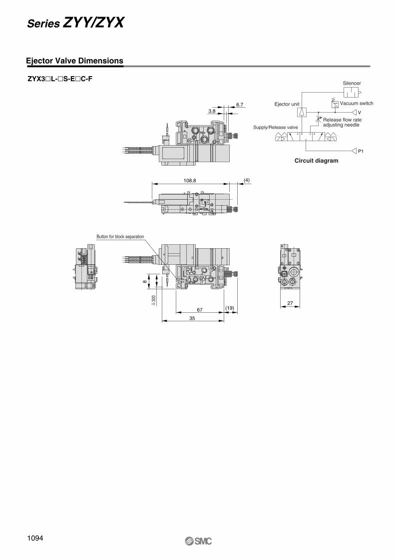
ZYX3�L-�S-E�C-F
Circuit diagram
(4)
8
35
108.8
(19)27
67
6.73.8
- -+
V
Button for block separation
300
~ =
1094
Series ZYY/ZYX
P1067-P1100-E.qxd 08.9.30 3:05 PM Page 1094
Vacuum switch
Supply/Release valve
V
P1
Release flow rateadjusting needle
Ejector unit
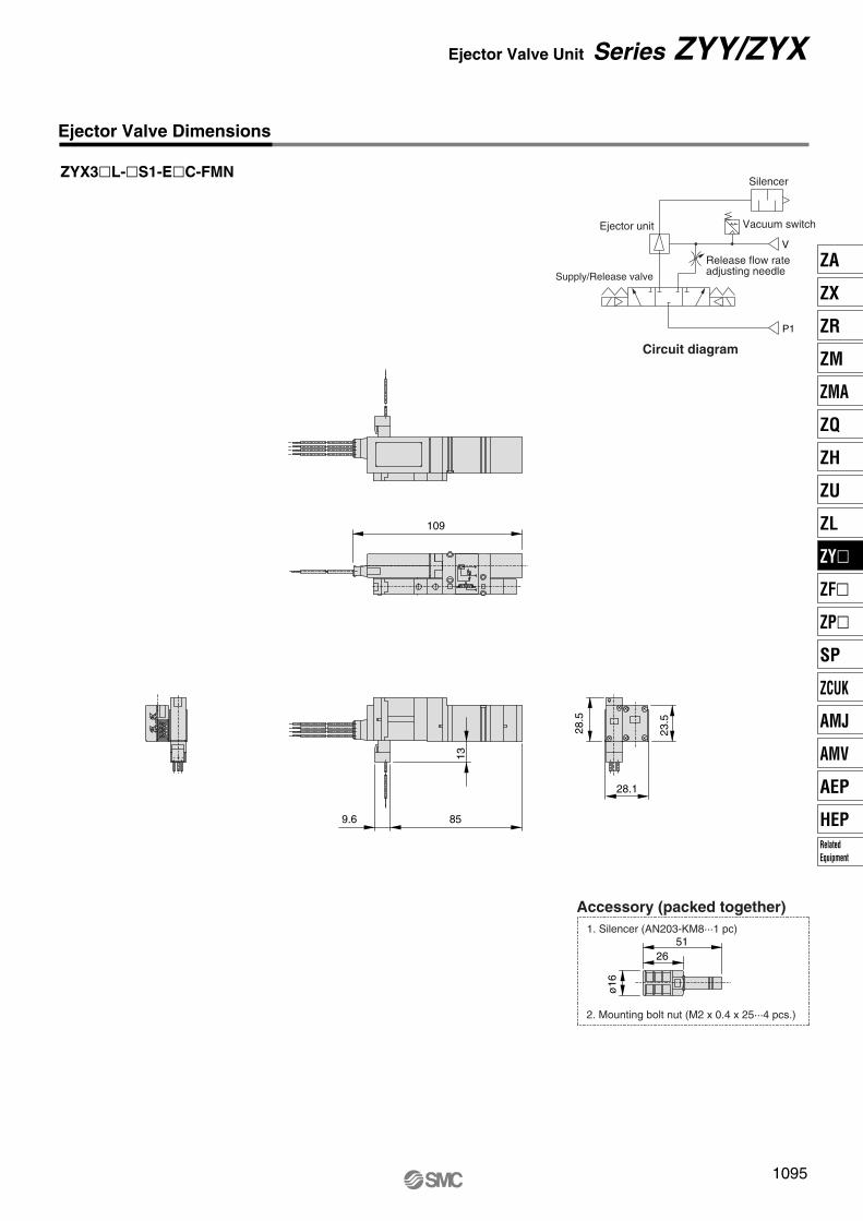
Ejector Valve Dimensions
ZYX3�L-�S1-E�C-FMN
109
9.6 85
28.5
23.5
28.1
13
5126
ø16
Accessory (packed together)
2. Mounting bolt nut (M2 x 0.4 x 25···4 pcs.)
1. Silencer (AN203-KM8···1 pc)
- -+
Circuit diagram
Silencer
1095
Ejector Valve Unit Series ZYY/ZYX
ZA
ZX
ZR
ZM
ZMA
ZQ
ZH
ZU
ZL
ZY�
ZF�
ZP�
SP
ZCUK
AMJ
AMV
AEP
HEPRelatedEquipment
P1067-P1100-E.qxd 08.9.30 3:05 PM Page 1095

Vacuum switch
Silencer
Supply/Release valve
V
P1
Release flow rateadjusting needle
Ejector unit
6.8
7.4 85
5126
ø16
Accessory (packed together)
2. Mounting bolt nut (M2 x 0.4 x 25···4 pcs.)
1. Silencer (AN203-KM8···1 pc)
Ejector Valve Dimensions
ZYX3�L-�S1-E�C-MN
Circuit diagram
1096
Series ZYY/ZYX
P1067-P1100-E.qxd 08.9.30 3:05 PM Page 1096

Ejector Valve Dimensions
ZYY3000-PA (Plug-in assembly)
ZYY3000-NPA (Non plug-in assembly)
86
33.6
27
33.3
33.6
106
27
33.3
1097
Ejector Valve Unit Series ZYY/ZYX
ZA
ZX
ZR
ZM
ZMA
ZQ
ZH
ZU
ZL
ZY�
ZF�
ZP�
SP
ZCUK
AMJ
AMV
AEP
HEPRelatedEquipment
P1067-P1100-E.qxd 08.9.30 3:05 PM Page 1097

The length of the standard accessory DIN rail is calculated with the formula below.
C1 Value SelectionSeparate wiring type
Connector box type
D-sub connector 25 pin type
Flat cable type
Terminal block 9 pole type
Terminal block 18 pole type
33
86
(mm)
54
75
81.8
94.3
132
126
Serial transmission type
Ejector valve
End plate assembly L End plate assembly R
L4
5.25
16.516.5
10.5
27 16.5
L1 : Rail overall length
L2 : Mounting screw length
L3 : Manifold overall length
8 5.5
DIN rail
Solenoid valve
Supply/Exhaust block
Indication exampleIn the case of ZZYY3-45-04D-C6∗SY3140-5LZ∗SY3240-5LZ∗SY3340-5LZ∗ZYY35LZ-10S-E15Cthe dimensions areL1 = 135.5 mmL2 = 125 mmL3 = 108 mmL4 = 13.75 mm
Manifold overall length (L3) = (27 x Number of ejector valve stations) + (10.5 x Number of solenoid valve stations) + (16.5 x Number of supply/exhaust block stations) + C1 [mm]Note) In the case of ejector valves only (without solenoid valves), calculate the number of solenoid valve stations and supply/exhaust block stations as “0”.Number of mounting holes (N) = (L3/12.5 + 1): Decimal fractions are truncatedDIN rail overall length (L1) = N x 12.5 + 23 [mm]Mounting screw length (L2) = L1 – 10.5 [mm]Rail length on one side (L4) = (L1 – L3)/2 [mm]
Stations
U side D side
45
45-
45F
45P�
45T
45T1
45S�
45S1�
45S2
45S3
ANA
r ewq
1098
Series ZYY/ZYX
Dimensions of DIN Rail Mounting Unit for ZYY3000/ZYX3000 Manifold
P1067-P1100-E.qxd 08.9.30 3:05 PM Page 1098
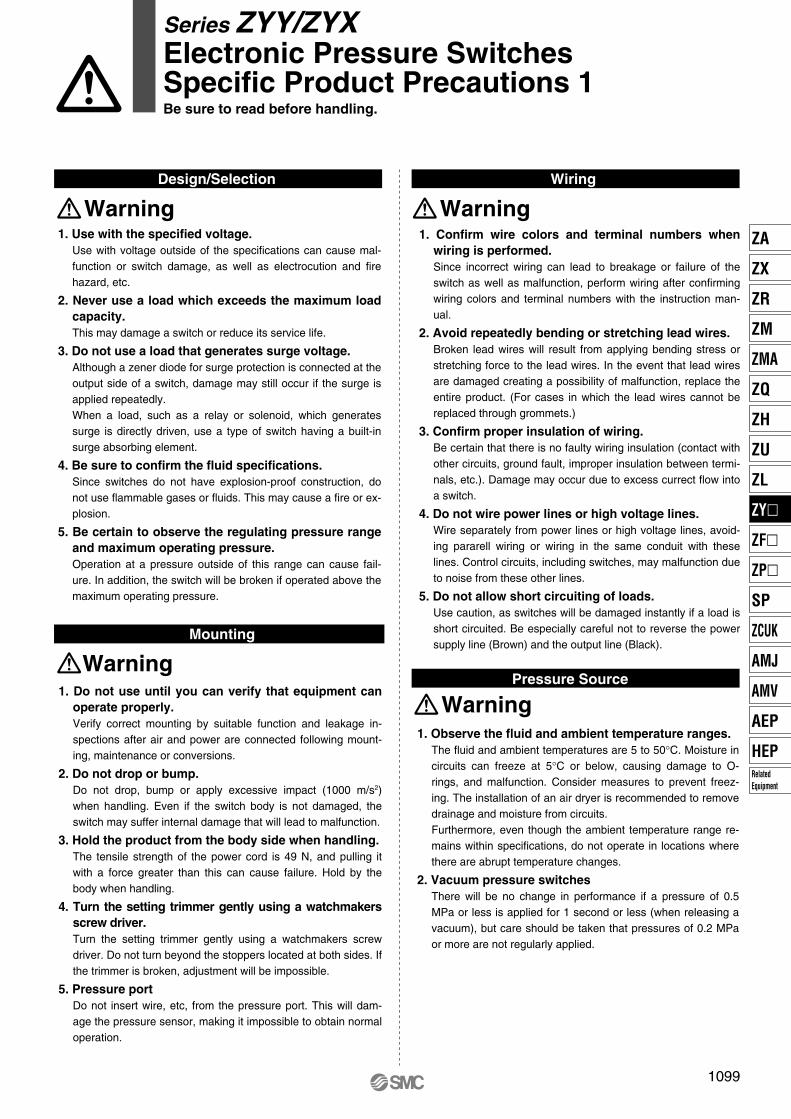
WiringDesign/Selection
Warning Warning
Mounting
Warning
WarningPressure Source
1. Use with the specified voltage.Use with voltage outside of the specifications can cause mal-function or switch damage, as well as electrocution and fire hazard, etc.
2. Never use a load which exceeds the maximum load capacity.This may damage a switch or reduce its service life.
3. Do not use a load that generates surge voltage.Although a zener diode for surge protection is connected at the output side of a switch, damage may still occur if the surge is applied repeatedly. When a load, such as a relay or solenoid, which generates surge is directly driven, use a type of switch having a built-in surge absorbing element.
4. Be sure to confirm the fluid specifications.Since switches do not have explosion-proof construction, do not use flammable gases or fluids. This may cause a fire or ex-plosion.
5. Be certain to observe the regulating pressure range and maximum operating pressure.Operation at a pressure outside of this range can cause fail-ure. In addition, the switch will be broken if operated above the maximum operating pressure.
1. Confirm wire colors and terminal numbers when wiring is performed.Since incorrect wiring can lead to breakage or failure of the switch as well as malfunction, perform wiring after confirming wiring colors and terminal numbers with the instruction man-ual.
2. Avoid repeatedly bending or stretching lead wires.Broken lead wires will result from applying bending stress or stretching force to the lead wires. In the event that lead wires are damaged creating a possibility of malfunction, replace the entire product. (For cases in which the lead wires cannot be replaced through grommets.)
3. Confirm proper insulation of wiring.Be certain that there is no faulty wiring insulation (contact with other circuits, ground fault, improper insulation between termi-nals, etc.). Damage may occur due to excess currect flow into a switch.
4. Do not wire power lines or high voltage lines.Wire separately from power lines or high voltage lines, avoid-ing pararell wiring or wiring in the same conduit with these lines. Control circuits, including switches, may malfunction due to noise from these other lines.
5. Do not allow short circuiting of loads.Use caution, as switches will be damaged instantly if a load is short circuited. Be especially careful not to reverse the power supply line (Brown) and the output line (Black).
1. Do not use until you can verify that equipment can operate properly.Verify correct mounting by suitable function and leakage in-spections after air and power are connected following mount-ing, maintenance or conversions.
2. Do not drop or bump.Do not drop, bump or apply excessive impact (1000 m/s2) when handling. Even if the switch body is not damaged, the switch may suffer internal damage that will lead to malfunction.
3. Hold the product from the body side when handling.The tensile strength of the power cord is 49 N, and pulling it with a force greater than this can cause failure. Hold by the body when handling.
4. Turn the setting trimmer gently using a watchmakers screw driver.Turn the setting trimmer gently using a watchmakers screw driver. Do not turn beyond the stoppers located at both sides. If the trimmer is broken, adjustment will be impossible.
5. Pressure portDo not insert wire, etc, from the pressure port. This will dam-age the pressure sensor, making it impossible to obtain normal operation.
1. Observe the fluid and ambient temperature ranges. The fluid and ambient temperatures are 5 to 50°C. Moisture in circuits can freeze at 5°C or below, causing damage to O-rings, and malfunction. Consider measures to prevent freez-ing. The installation of an air dryer is recommended to remove drainage and moisture from circuits. Furthermore, even though the ambient temperature range re-mains within specifications, do not operate in locations where there are abrupt temperature changes.
2. Vacuum pressure switches There will be no change in performance if a pressure of 0.5 MPa or less is applied for 1 second or less (when releasing a vacuum), but care should be taken that pressures of 0.2 MPa or more are not regularly applied.
1099
Series ZYY/ZYXElectronic Pressure SwitchesSpecific Product Precautions 1Be sure to read before handling.
ZA
ZX
ZR
ZM
ZMA
ZQ
ZH
ZU
ZL
ZY�
ZF�
ZP�
SP
ZCUK
AMJ
AMV
AEP
HEPRelatedEquipment
P1067-P1100-E.qxd 08.9.30 3:05 PM Page 1099
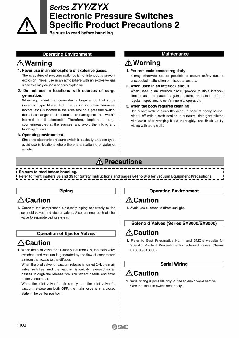
Maintenance
WarningOperating Environment
Warning
Piping Operating Environment
Caution Caution
Operation of Ejector Valves
Caution
Solenoid Valves (Series SY3000/SX3000)
Caution
Serial Wiring
Caution
Precautions
1. Never use in an atmosphere of explosive gases.The strucuture of pressure switches is not intended to prevent explosion. Never use in an atmosphere with an explosive gas since this may cause a serious explosion.
2. Do not use in locations with sources of surge generation. When equipment that generates a large amount of surge (solenoid type lifters, high frequency induction furnaces, motors, etc.) is located in the area around a pressure switch, thers is a danger of deterioration or damage to the switch’s internal circuit elements. Therefore, implement surge countermeasures at the sources, and avoid the mixing and touching of lines.
3. Operating environmentSince the electronic pressure switch is basically an open type, avoid use in locations where there is a scattering of water or oil, etc.
1. Perform maintenance regularly. It may otherwise not be possible to assure safety due to unexpected malfunction or misoperation, etc.
2. When used in an interlock circuit When used in an interlock circuit, provide multiple interlock circuits as a precaution against failure, and also perform regular inspections to confirm normal operation.
3. When the body requires cleaning Use a soft cloth to clean the case. In case of heavy soiling, wipe it off with a cloth soaked in a neutral detergent diluted with water after wringing it out thoroughly, and finish up by wiping with a dry cloth.
1. Connect the compressed air supply piping separately to the solenoid valves and ejector valves. Also, connect each ejector valve to separate piping system.
1. When the pilot valve for air supply is turned ON, the main valve switches, and vacuum is generated by the flow of compressed air from the nozzle to the diffuser. When the pilot valve for vacuum release is turned ON, the main valve switches, and the vacuum is quickly released as air passes through the release flow adjustment needle and flows to the vacuum port. When the pilot valve for air supply and the pilot valve for vacuum release are both OFF, the main valve is in a closed state in the center position.
1. Avoid use exposed to direct sunlight.
1. Refer to Best Pneumatics No. 1 and SMC,s website for
Specific Product Precautions for solenoid valves (Series SY3000/SX3000).
1. Serial wiring is possible only for the solenoid valve section. Wire the vacuum switch separately.
Be sure to read before handling.Refer to front matters 38 and 39 for Safety Instructions and pages 844 to 846 for Vacuum Equipment Precautions.
1100
Series ZYY/ZYXElectronic Pressure SwitchesSpecific Product Precautions 2Be sure to read before handling.
P1067-P1100-E.qxd 08.9.30 3:05 PM Page 1100
Related Documents