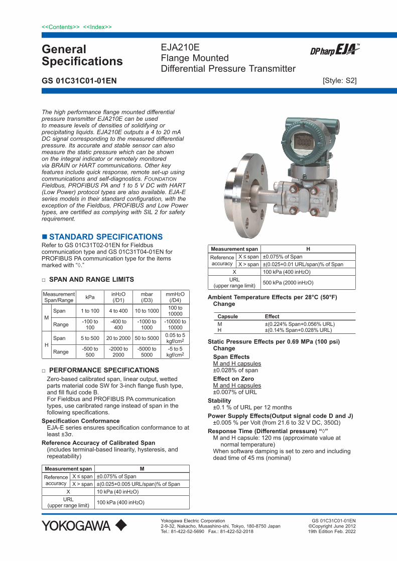
General Specifications <<Contents>> <<Index>> EJA210E Flange Mounted Differential Pressure Transmitter Yokogawa Electric Corporation 2-9-32, Nakacho, Musashino-shi, Tokyo, 180-8750 Japan Tel.: 81-422-52-5690 Fax.: 81-422-52-2018 GS 01C31C01-01EN GS 01C31C01-01EN ©Copyright June 2012 19th Edition Feb. 2022 The high performance flange mounted differential pressure transmitter EJA210E can be used to measure levels of densities of solidifying or precipitating liquids. EJA210E outputs a 4 to 20 mA DC signal corresponding to the measured differential pressure. Its accurate and stable sensor can also measure the static pressure which can be shown on the integral indicator or remotely monitored via BRAIN or HART communications. Other key features include quick response, remote set-up using communications and self-diagnostics. FOUNDATION Fieldbus, PROFIBUS PA and 1 to 5 V DC with HART (Low Power) protocol types are also available. EJA-E series models in their standard configuration, with the exception of the Fieldbus, PROFIBUS and Low Power types, are certified as complying with SIL 2 for safety requirement. STANDARD SPECIFICATIONS Refer to GS 01C31T02-01EN for Fieldbus communication type and GS 01C31T04-01EN for PROFIBUS PA communication type for the items marked with “◊.” □ SPAN AND RANGE LIMITS Measurement Span/Range kPa inH2O (/D1) mbar (/D3) mmH2O (/D4) M Span 1 to 100 4 to 400 10 to 1000 100 to 10000 Range -100 to 100 -400 to 400 -1000 to 1000 -10000 to 10000 H Span 5 to 500 20 to 2000 50 to 5000 0.05 to 5 kgf/cm 2 Range -500 to 500 -2000 to 2000 -5000 to 5000 -5 to 5 kgf/cm 2 □ PERFORMANCE SPECIFICATIONS Zero-based calibrated span, linear output, wetted parts material code SW for 3-inch flange flush type, and fill fluid code B. For Fieldbus and PROFIBUS PA communication types, use caribrated range instead of span in the following specifications. Specification Conformance EJA-E series ensures specification conformance to at least ±3σ. Reference Accuracy of Calibrated Span (includes terminal-based linearity, hysteresis, and repeatability) Measurement span M Reference accuracy X ≤ span ±0.075% of Span X > span ±(0.025+0.005 URL/span)% of Span X 10 kPa (40 inH2O) URL (upper range limit) 100 kPa (400 inH2O) Measurement span H Reference accuracy X ≤ span ±0.075% of Span X > span ±(0.025+0.01 URL/span)% of Span X 100 kPa (400 inH2O) URL (upper range limit) 500 kPa (2000 inH2O) Ambient Temperature Effects per 28°C (50°F) Change Capsule Effect M H ±(0.224% Span+0.056% URL) ±(0.14% Span+0.028% URL) Static Pressure Effects per 0.69 MPa (100 psi) Change Span Effects M and H capsules ±0.028% of span Effect on Zero M and H capsules ±0.007% of URL Stability ±0.1 % of URL per 12 months Power Supply Effects(Output signal code D and J) ±0.005 % per Volt (from 21.6 to 32 V DC, 350Ω) Response Time (Differential pressure) “◊” M and H capsule: 120 ms (approximate value at normal temperature) When software damping is set to zero and including dead time of 45 ms (nominal) [Style: S2]

Welcome message from author
This document is posted to help you gain knowledge. Please leave a comment to let me know what you think about it! Share it to your friends and learn new things together.
Transcript
GeneralSpecifications
<<Contents>> <<Index>>
EJA210EFlange MountedDifferential Pressure Transmitter
Yokogawa Electric Corporation2-9-32, Nakacho, Musashino-shi, Tokyo, 180-8750 JapanTel.: 81-422-52-5690 Fax.: 81-422-52-2018
GS 01C31C01-01EN
GS 01C31C01-01EN©Copyright June 201219th Edition Feb. 2022
The high performance flange mounted differential pressure transmitter EJA210E can be used to measure levels of densities of solidifying or precipitating liquids. EJA210E outputs a 4 to 20 mA DC signal corresponding to the measured differential pressure. Its accurate and stable sensor can also measure the static pressure which can be shown on the integral indicator or remotely monitored via BRAIN or HART communications. Other key features include quick response, remote set-up using communications and self-diagnostics. FOUNDATION Fieldbus, PROFIBUS PA and 1 to 5 V DC with HART (Low Power) protocol types are also available. EJA-E series models in their standard configuration, with the exception of the Fieldbus, PROFIBUS and Low Power types, are certified as complying with SIL 2 for safety requirement.
STANDARD SPECIFICATIONSRefer to GS 01C31T02-01EN for Fieldbus communication type and GS 01C31T04-01EN for PROFIBUS PA communication type for the items marked with “◊.”
SPANANDRANGELIMITS
MeasurementSpan/Range kPa inH2O
(/D1)mbar(/D3)
mmH2O(/D4)
MSpan 1 to 100 4 to 400 10 to 1000 100 to
10000
Range -100 to 100
-400 to 400
-1000 to 1000
-10000 to 10000
HSpan 5 to 500 20 to 2000 50 to 5000 0.05 to 5
kgf/cm2
Range -500 to 500
-2000 to 2000
-5000 to 5000
-5 to 5 kgf/cm2
PERFORMANCESPECIFICATIONSZero-based calibrated span, linear output, wetted parts material code SW for 3-inch flange flush type, and fill fluid code B.For Fieldbus and PROFIBUS PA communication types, use caribrated range instead of span in the following specifications.
SpecificationConformanceEJA-E series ensures specification conformance to at least ±3σ.
ReferenceAccuracyofCalibratedSpan(includes terminal-based linearity, hysteresis, and repeatability)
Measurementspan MReferenceaccuracy
X ≤ span ±0.075% of SpanX > span ±(0.025+0.005 URL/span)% of Span
X 10 kPa (40 inH2O)URL
(upper range limit) 100 kPa (400 inH2O)
Measurementspan HReferenceaccuracy
X ≤ span ±0.075% of SpanX > span ±(0.025+0.01 URL/span)% of Span
X 100 kPa (400 inH2O)URL
(upper range limit) 500 kPa (2000 inH2O)
AmbientTemperatureEffectsper28°C(50°F)Change
Capsule EffectMH
±(0.224% Span+0.056% URL)±(0.14% Span+0.028% URL)
StaticPressureEffectsper0.69MPa(100psi)Change
SpanEffectsM and H capsules±0.028% of span
EffectonZeroM and H capsules±0.007% of URL
Stability±0.1 % of URL per 12 months
PowerSupplyEffects(OutputsignalcodeDandJ)±0.005 % per Volt (from 21.6 to 32 V DC, 350Ω)
ResponseTime(Differentialpressure)“◊”M and H capsule: 120 ms (approximate value at
normal temperature)When software damping is set to zero and including dead time of 45 ms (nominal)
[Style: S2]
2
All Rights Reserved. Copyright © 2012, Yokogawa Electric Corporation
<<Contents>> <<Index>>
GS 01C31C01-01EN
StaticPressureSignalRangeandAccuracy (FormonitoringviacommunicationoronindicatorforBRAINandHARTcommunicationtype.Includesterminal-basedlinearity,hysteresis,andrepeatability)
RangeUpper Range Value and Lower Range Value of the static pressure can be set in the range between 0 and Maximum Working Pressure (MWP*). The upper range value must be greater than the lower range value. Minimum setting span is 0.5 MPa (73 psi).
* : Maximum Working Pressure (MWP) is within flange rating pressure.
AccuracyAbsolute Pressure1 MPa or higher: ±0.5% of spanLess than 1 MPa: ±0.5%×(1 MPa/span) of spanGauge Pressure ReferenceGauge pressure reference is 1013 hPa (1 atm)
Note: Gauge pressure variable is based on the above fixed reference and thus subject to be affected by the change of atomospheric pressure.
FUNCTIONALSPECIFICATIONSOutput“◊” For4to20mAHART/BRAIN (OutputsignalcodeDandJ)Two wire 4 to 20 mA DC output with digital communications.BRAIN or HART FSK protocol are superimposed on the 4 to 20 mA signal.Output range: 3.6 mA to 21.6 mAOutput limits conform to NAMUR NE43 can be preset by option code C2 or C3.For1to5VHART(OutputsignalcodeQ)Three or four wire low power 1 to 5 V DC output with HART, linear or square root programmable. HART protocol are superimposed on the 1 to 5 V DC signal.Output range: 0.9 V to 5.4 V DC
FailureAlarm For4to20mAHART/BRAIN (OutputsignalcodeDandJ)Output status at CPU failure and hardware error;
Up-scale: 110%, 21.6 mA DC or more (standard)Down-scale: −5%, 3.2 mA DC or less
For1to5VHART(OutputsignalcodeQ)Analog output status at CPU failure and hardware error;
Up-scale: 110%, 5.4 V DC or more (standard) Down-scale: −5%, 0.8 V DC or less
DampingTimeConstant(1storder)Amplifier damping time constant is adjustable from 0.00 to 100.00 s by software and added to response time.
Note: For BRAIN protocol type, when amplifier software damping is set to less than 0.5 s, communication may occasionally be unavailble during the operation, especially while output changes dynamically. The default setting of damping ensures stable communication.
UpdatePeriod“◊”Differential pressure: 45 msStatic pressure: 360 ms
ZeroAdjustmentLimitsZero can be fully elevated or suppressed, within the lower and upper range limits of the capsule.
ExternalZeroAdjustmentExternal zero is continuously adjustable with 0.01% incremental resolution of span. Re-range can be done locally using the digital indicator with rangesetting switch.
IntegralIndicator(LCDdisplay,optional)“◊”5-digit numerical display, 6-digit unit display and bar graph.The indicator is configurable to display one or up to four of the following variables periodically.;Measured differential pressure, differential pressure in %, scaled differential pressure, measured static pressure. See also “Factory Setting.”
LocalParameterSetting (OutputsignalcodeD,JandQ)Parameter configuration by the external zero adjustment screw and push button (Integral indicator code E) offers easy and quick setup for parameters of Loop test, Tag number, Unit, LRV, URV, Damping, Output mode (linear/square root), Display out 1, and Re-range by applying actual pressure (LRV/URV) and Device Information.
SelfDiagnosticsCPU failure, hardware failure, configuration error, process alarm for differential pressure, static pressure or capsule temperature.User-configurable process high/low alarm for differential pressure and static pressure is also available.
SignalCharacterizer (OutputsignalcodeD,JandQ)User-configurable 10-segment signal characterizer for 4 to 20 mA output.
SILCertificationEJA-E series transmitters except Fieldbus, PROFIBUS PA and 1-5V DC with HART (Low Power) communication types are certified in compliance with the following standards;IEC 61508: 2010;Functional Safety of Electrical/electronic/programmable electronic related systems; SIL 2 capability for single transmitter use, SIL 3 capability for dual transmitter use.Reliability Data different depending on hardware and software revision.For details, refer to Functional Safety Data Sheet. (Document number: TI 01C25A05-01EN or TI 01C25A05-21EN for option code SLT )The document can be downloaded from the website of Yokogawa. (Website address: https://www.yokogawa.com/solutions/products-platforms/field-instruments/)
Nov. 20, 2019-00
3<<Contents>> <<Index>>
All Rights Reserved. Copyright © 2012, Yokogawa Electric Corporation GS 01C31C01-01EN
NORMALOPERATINGCONDITION (Optionalfeaturesorapprovalcodesmayaffectlimits.)
AmbientTemperatureLimits−40 to 85°C (−40 to 185°F)−30 to 80°C (−22 to 176°F) with LCD display
(Note: The ambient temperature limits must be within the fill fluid operating temperature range, see table 1.)
ProcessTemperatureLimitsHigh pressure side: See table 1.Low pressure side: −40 to 120°C (−40 to 248°F)
AmbientHumidityLimits0 to 100% RH
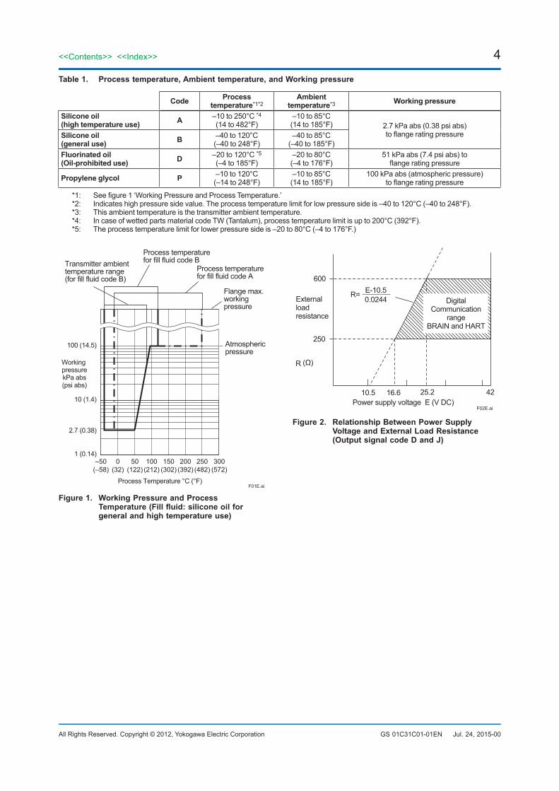
WorkingPressureLimitsSee table 1.For atmospheric pressure or below, see figure 1.
Supply&LoadRequirements (OutputsignalcodeDandJ.Optionalfeaturesorapprovalcodesmayaffectelectricalrequirements.)With 24 V DC supply, up to a 550Ω load can beused. See figure 2.
SupplyVoltage“◊” For4to20mAHART/BRAIN (OutputsignalcodeDandJ)10.5 to 42 V DC for general use and flameproof type.10.5 to 32 V DC for lightning protector
(option code /A.)10.5 to 30 V DC for intrinsically safe, type n, or non-
incendive.Minimum voltage limited at 16.6 V DC for digital
communications, BRAIN and HARTFor1to5VHART(OutputsignalcodeQ)Power supply :9 to 28 V DC for general use and flame proof type. Power Consumption : 0.96 mA to 3 mA, 27 mW
Loadfor4to20mAHART/BRAIN (OutputsignalcodeDandJ)
0 to 1290Ω for operation250 to 600Ω for digital communication
OutputLoadfor1to5VHART (OutputsignalcodeQ)
1 MΩ or greater (meter input impedance)Note that with three-wire connection, the cable length may affect the measurement accuracy of the output signal.
CommunicationRequirements“◊” (Approval codes may affect electrical requirements.)
BRAIN Communicationdistance
Up to 2 km (1.25 miles) when using CEV polyethylene-insulated PVC-sheathed cables. Communication distance varies depending on type of cable used.
Loadcapacitance0.22 µF or less
Loadinductance3.3 mH or less
Inputimpedanceofcommunicatingdevice10 kΩ or more at 2.4 kHz.
July 1, 2021-00
EMCConformityStandardsEN 61326-1 Class A, Table2EN 61326-2-3EN 61326-2-5 (for fieldbus)
EuropeanPressureEquipmentDirective 2014/68/EUSound Engineering Practice
EURoHSDirectiveEN IEC 63000
SafetyRequirementStandardsEN 61010-1, C22.2 No.61010-1• Installation category: I
(Anticipated transient overvoltage 330 V)• Pollution degree: 2• Indoor/Outdoor use
4
All Rights Reserved. Copyright © 2012, Yokogawa Electric Corporation
<<Contents>> <<Index>>
GS 01C31C01-01EN
Table1. Processtemperature,Ambienttemperature,andWorkingpressure
Code Processtemperature*1*2
Ambienttemperature*3 Workingpressure
Siliconeoil(hightemperatureuse) A –10 to 250°C *4
(14 to 482°F)–10 to 85°C(14 to 185°F) 2.7 kPa abs (0.38 psi abs)
to flange rating pressureSiliconeoil(generaluse) B –40 to 120°C
(–40 to 248°F)–40 to 85°C
(–40 to 185°F)Fluorinatedoil(Oil-prohibiteduse) D –20 to 120°C *5
(–4 to 185°F)–20 to 80°C(–4 to 176°F)
51 kPa abs (7.4 psi abs) to flange rating pressure
Propyleneglycol P –10 to 120°C(–14 to 248°F)
–10 to 85°C(14 to 185°F)
100 kPa abs (atmospheric pressure)to flange rating pressure
*1: See figure 1 ‘Working Pressure and Process Temperature.’*2: Indicates high pressure side value. The process temperature limit for low pressure side is –40 to 120°C (–40 to 248°F).*3: This ambient temperature is the transmitter ambient temperature.*4: In case of wetted parts material code TW (Tantalum), process temperature limit is up to 200°C (392°F).*5: The process temperature limit for lower pressure side is –20 to 80°C (–4 to 176°F.)
2.7 (0.38)
100 (14.5)
1 (0.14)
10 (1.4)
–50(–58)
0(32)
50(122)
100(212)
150(302)
200(392)
250(482)
300(572)
F01E.ai
Process temperaturefor fill fluid code B
Process temperaturefor fill fluid code A
Flange max.working pressure
Atmosphericpressure
Transmitter ambienttemperature range(for fill fluid code B)
Process Temperature °C (°F)
Working pressurekPa abs(psi abs)
Figure1. WorkingPressureandProcessTemperature(Fillfluid:siliconeoilforgeneralandhightemperatureuse)
E-10.5 0.0244
(Ω)
Power supply voltage E (V DC)
600
250
R
10.5 16.6 25.2 42
Externalloadresistance
DigitalCommunication
rangeBRAIN and HART
R=
F02E.ai
Figure2. RelationshipBetweenPowerSupplyVoltageandExternalLoadResistance (OutputsignalcodeDandJ)
Jul. 24, 2015-00
5<<Contents>> <<Index>>
All Rights Reserved. Copyright © 2012, Yokogawa Electric Corporation GS 01C31C01-01EN
PHYSICALSPECIFICATIONSProcessconnections Highpressureside:
Flange connectedSee the following table.
Table2. Flangesizeandrating
Processconnectionstyle Size Flange
Flush type3-inch2-inch11/2-inch*
JIS 10K, 20KANSI Class 150, 300JPI Class 150, 300DIN PN10/16, 25/40
Extended type 4-inch3-inch
JIS 10K, 20KANSI Class 150, 300JPI Class 150, 300DIN PN10/16, 25/40
* : Flushing connection rings are always attached. Lowpressureside:
ThreadedSee “MODEL AND SUFFIX CODES.”Process connection of cover flange: IEC61518
GasketContactSurfaceSee the following table.
Table3. Gasketcontactsurface
Flange JIS/JPI/DIN ANSI
Wetted parts material codeSW,SE,WW,WE
HW,TW
SW,SE,WW,WE
HW,TW
Gasket contact Surface
Serration*1 Flat (No serration)
: Applicable : Not applicable*1: ANSI B16.5
ElectricalConnectionsSee “MODEL AND SUFFIX CODES.”
WettedPartsMaterials Highpressureside:
Refer to “MODEL AND SUFFIX CODES” Flushingconnectionring(optional) RingandVent/Drainplugs
Refer to “MODEL AND SUFFIX CODES” (Spiral)gasketfortransmitterside
316L SST (Hoop), PTFE Teflon (Filler) Lowpressureside: Diaphragm,CoverFlange,ProcessConnector,
CapsuleGasket,andVent/DrainplugRefer to “MODEL AND SUFFIX CODES”
ProcessconnectorgasketPTFE Teflon
Non-wettedPartsMaterials ProcessFlange
Refer to “MODEL AND SUFFIX CODES” Bolting
B7 carbon steel, 316L SST or 660 SST Housing
• Low copper cast aluminum alloy• Low copper cast aluminum alloy with corrosion
resistance properties (copper content ≤ 0.03%, iron content ≤ 0.15%) (optional)
• ASTM CF-8M Stainless steel (optional)
Mar. 11, 2019-00
Coatingofhousing[for aluminum housing]Polyester resin powder coating Mint-green paint (Munsell 5.6BG 3.3/2.9 or its equivalent)[for option code /P or /X2]Epoxy and polyurethane resin solvent coating
DegreesofprotectionIP66/IP67, Type 4X
CoverO-ringsBuna-N, fluoro-rubber (optional)
Nameplateandtag316 SST
FillfluidSilicone oil, Propylene glycol, Fluorinated oil (optional)
Weight Flushtype
(3-inch ANSI Class150 flange; without integral indicator, and process connector.)
General use (fill fluid code B or P): 8.3 kg (18.3 lbs) High temperature use (fill fluid code A):
9.0 kg (19.8 lbs) Extendedtype
(4-inch ANSI Class150 flange, extension length (X2) = 100 mm; without integral indicator, and process connector.)
General use (fill fluid code B or P): 12.8 kg (28.2 lbs)High temperature use (fill fluid code A):
13.5 kg (29.8 lbs)
Add 1.5kg (3.3lb) for Amplifier housing code 2.
<RelatedInstruments>“◊”Power Distributor: Refer to GS 01B04T01-02E or
GS 01B04T02-02EBRAIN TERMINAL: Refer to GS 01C00A11-00E
<Reference>• ; Registered trademark of Yokogawa
Electric Corporation.• FieldMate; Registered trademark of Yokogawa
Electric Corporation.• Teflon; Trademark of E.I. DuPont de Nemours &
Co.• Hastelloy; Trademark of Haynes International Inc.• HART®: Registered trademark of FieldComm
Group.• FOUNDATION Fieldbus; Tradmark of FieldComm
Group.• PROFIBUS; Registered trademark of Profibus
Nutzerorganisation e.v., Karlsruhe, Germany.Other company names and product names used in this material are registered trademarks or trademarks of their respective owners.
6
All Rights Reserved. Copyright © 2012, Yokogawa Electric Corporation
<<Contents>> <<Index>>
GS 01C31C01-01EN Oct. 24, 2014-00
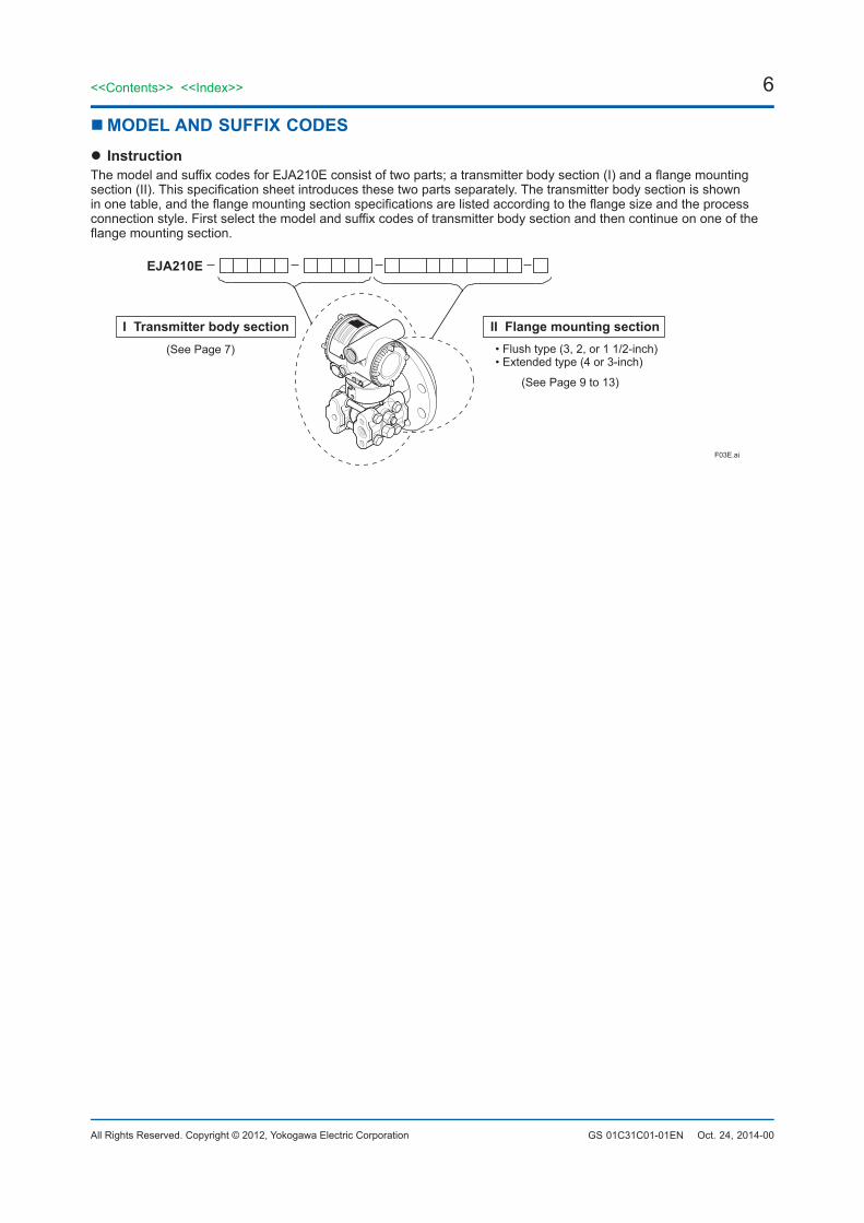
MODELANDSUFFIXCODES InstructionThe model and suffix codes for EJA210E consist of two parts; a transmitter body section (I) and a flange mounting section (II). This specification sheet introduces these two parts separately. The transmitter body section is shown in one table, and the flange mounting section specifications are listed according to the flange size and the process connection style. First select the model and suffix codes of transmitter body section and then continue on one of the flange mounting section.
F03E.ai
EJA210E
I Transmitter body section(See Page 7) • Flush type (3, 2, or 1 1/2-inch)
• Extended type (4 or 3-inch)
(See Page 9 to 13)
II Flange mounting section
7<<Contents>> <<Index>>
All Rights Reserved. Copyright © 2012, Yokogawa Electric Corporation GS 01C31C01-01EN
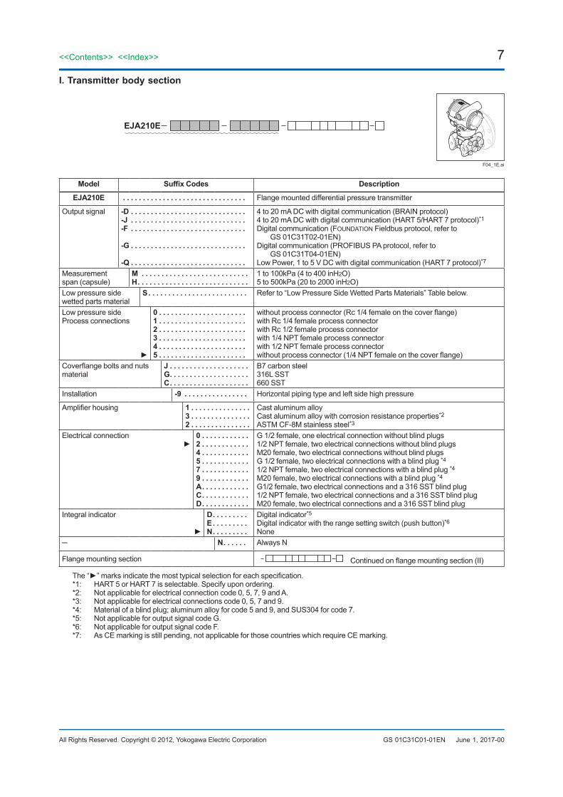
I.Transmitterbodysection
F04_1E.ai
EJA210E
Model SuffixCodes Description
EJA210E ............................... Flange mounted differential pressure transmitter
Output signal -D. . . . . . . . . . . . . . . . . . . . . . . . . . . . .-J . . . . . . . . . . . . . . . . . . . . . . . . . . . . .-F . . . . . . . . . . . . . . . . . . . . . . . . . . . . .
-G . . . . . . . . . . . . . . . . . . . . . . . . . . . . .
-Q . . . . . . . . . . . . . . . . . . . . . . . . . . . . .
4 to 20 mA DC with digital communication (BRAIN protocol)4 to 20 mA DC with digital communication (HART 5/HART 7 protocol)*1Digital communication (FOUNDATION Fieldbus protocol, refer to
GS 01C31T02-01EN)Digital communication (PROFIBUS PA protocol, refer to
GS 01C31T04-01EN)Low Power, 1 to 5 V DC with digital communication (HART 7 protocol)*7
Measurementspan (capsule)
M . . . . . . . . . . . . . . . . . . . . . . . . . . .H. . . . . . . . . . . . . . . . . . . . . . . . . . . .
1 to 100kPa (4 to 400 inH2O)5 to 500kPa (20 to 2000 inH2O)
Low pressure sidewetted parts material
S . . . . . . . . . . . . . . . . . . . . . . . . . Refer to “Low Pressure Side Wetted Parts Materials” Table below.
Low pressure sideProcess connections
0 . . . . . . . . . . . . . . . . . . . . . .1 . . . . . . . . . . . . . . . . . . . . . .2 . . . . . . . . . . . . . . . . . . . . . .3 . . . . . . . . . . . . . . . . . . . . . .4 . . . . . . . . . . . . . . . . . . . . . .5 . . . . . . . . . . . . . . . . . . . . . .
without process connector (Rc 1/4 female on the cover flange)with Rc 1/4 female process connectorwith Rc 1/2 female process connectorwith 1/4 NPT female process connectorwith 1/2 NPT female process connectorwithout process connector (1/4 NPT female on the cover flange)
Coverflange bolts and nuts material
J . . . . . . . . . . . . . . . . . . . .G. . . . . . . . . . . . . . . . . . . .C. . . . . . . . . . . . . . . . . . . .
B7 carbon steel316L SST660 SST
Installation -9 . . . . . . . . . . . . . . . . Horizontal piping type and left side high pressure
Amplifier housing 1 . . . . . . . . . . . . . . .3 . . . . . . . . . . . . . . .2 . . . . . . . . . . . . . . .
Cast aluminum alloyCast aluminum alloy with corrosion resistance properties*2
ASTM CF-8M stainless steel*3Electrical connection
0 . . . . . . . . . . . .2 . . . . . . . . . . . .4 . . . . . . . . . . . .5 . . . . . . . . . . . .7 . . . . . . . . . . . .9 . . . . . . . . . . . .A. . . . . . . . . . . .C. . . . . . . . . . . .D. . . . . . . . . . . .
G 1/2 female, one electrical connection without blind plugs1/2 NPT female, two electrical connections without blind plugsM20 female, two electrical connections without blind plugsG 1/2 female, two electrical connections with a blind plug *41/2 NPT female, two electrical connections with a blind plug *4M20 female, two electrical connections with a blind plug *4G1/2 female, two electrical connections and a 316 SST blind plug1/2 NPT female, two electrical connections and a 316 SST blind plugM20 female, two electrical connections and a 316 SST blind plug
Integral indicator
D. . . . . . . . .E . . . . . . . . .N. . . . . . . . .
Digital indicator*5Digital indicator with the range setting switch (push button)*6None
N. . . . . . Always N
Flange mounting section Continued on flange mounting section (II)
The “” marks indicate the most typical selection for each specification.*1: HART 5 or HART 7 is selectable. Specify upon ordering.*2: Not applicable for electrical connection code 0, 5, 7, 9 and A.*3: Not applicable for electrical connections code 0, 5, 7 and 9.*4: Material of a blind plug; aluminum alloy for code 5 and 9, and SUS304 for code 7.*5: Not applicable for output signal code G.*6: Not applicable for output signal code F.*7: As CE marking is still pending, not applicable for those countries which require CE marking.
June 1, 2017-00
8
All Rights Reserved. Copyright © 2012, Yokogawa Electric Corporation
<<Contents>> <<Index>>
GS 01C31C01-01EN
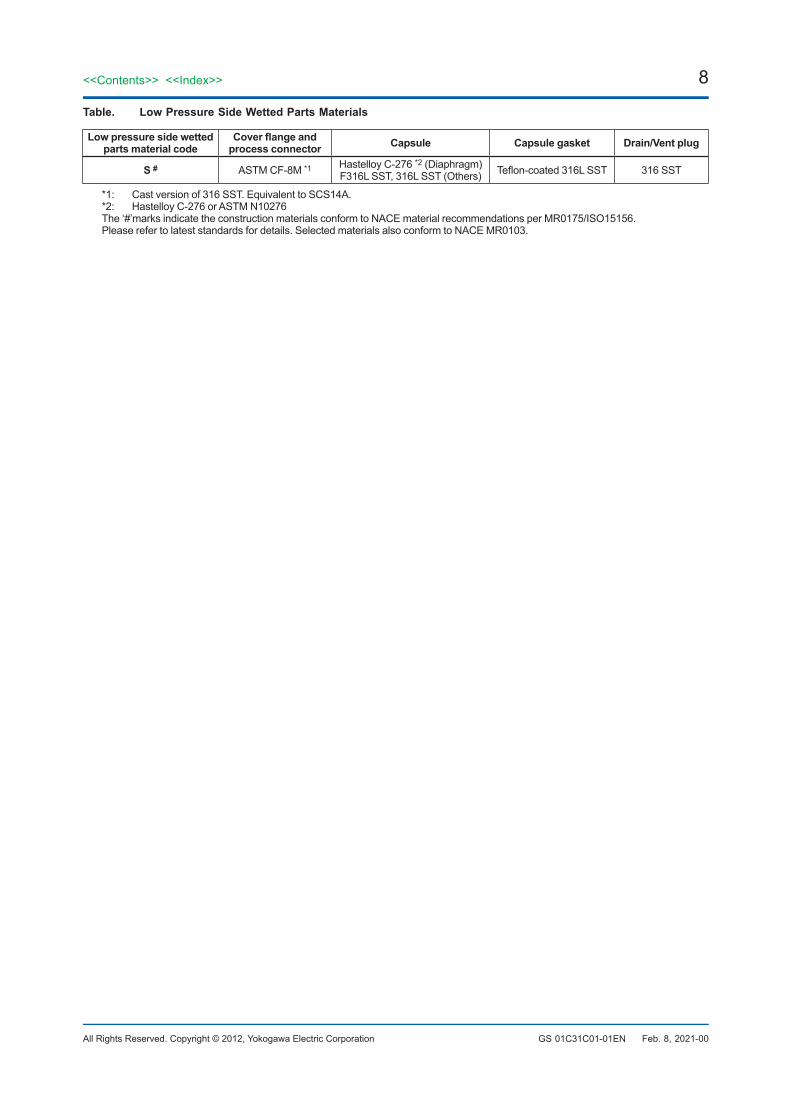
Table. LowPressureSideWettedPartsMaterials
Lowpressuresidewettedpartsmaterialcode
Coverflangeandprocessconnector Capsule Capsulegasket Drain/Ventplug
S # ASTM CF-8M *1 Hastelloy C-276 *2 (Diaphragm)F316L SST, 316L SST (Others) Teflon-coated 316L SST 316 SST
*1: Cast version of 316 SST. Equivalent to SCS14A.*2: Hastelloy C-276 or ASTM N10276The ‘#’marks indicate the construction materials conform to NACE material recommendations per MR0175/ISO15156.Please refer to latest standards for details. Selected materials also conform to NACE MR0103.
Feb. 8, 2021-00
9<<Contents>> <<Index>>
All Rights Reserved. Copyright © 2012, Yokogawa Electric Corporation GS 01C31C01-01EN
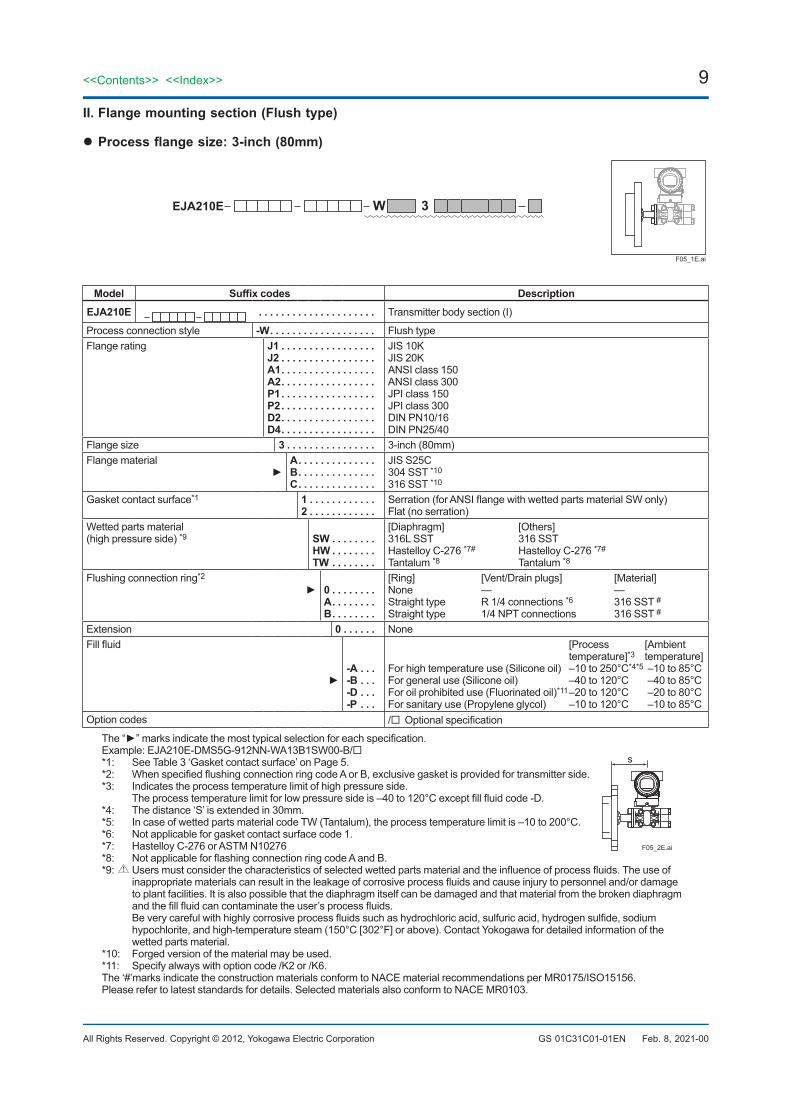
II.Flangemountingsection(Flushtype)
Processflangesize:3-inch(80mm)
F05_1E.ai
EJA210E W 3
Model Suffixcodes DescriptionEJA210E ..................... Transmitter body section (I)
Process connection style -W. . . . . . . . . . . . . . . . . . . Flush typeFlange rating J1 . . . . . . . . . . . . . . . . .
J2 . . . . . . . . . . . . . . . . .A1. . . . . . . . . . . . . . . . .A2. . . . . . . . . . . . . . . . .P1 . . . . . . . . . . . . . . . . .P2. . . . . . . . . . . . . . . . .D2. . . . . . . . . . . . . . . . .D4. . . . . . . . . . . . . . . . .
JIS 10KJIS 20KANSI class 150ANSI class 300JPI class 150JPI class 300DIN PN10/16DIN PN25/40
Flange size 3 . . . . . . . . . . . . . . . . 3-inch (80mm)Flange material
A. . . . . . . . . . . . . .B. . . . . . . . . . . . . .C. . . . . . . . . . . . . .
JIS S25C304 SST *10
316 SST *10
Gasket contact surface*1 1 . . . . . . . . . . . .2 . . . . . . . . . . . .
Serration (for ANSI flange with wetted parts material SW only)Flat (no serration)
Wetted parts material(high pressure side) *9 SW. . . . . . . .
HW . . . . . . . .TW. . . . . . . .
[Diaphragm] [Others]316L SST 316 SSTHastelloy C-276 *7# Hastelloy C-276 *7#
Tantalum *8 Tantalum *8 Flushing connection ring*2
0 . . . . . . . .A. . . . . . . .B. . . . . . . .
[Ring] [Vent/Drain plugs] [Material]None — —Straight type R 1/4 connections *6 316 SST #Straight type 1/4 NPT connections 316 SST #
Extension 0 . . . . . . NoneFill fluid
-A . . .-B. . .-D. . .-P . . .
[Process [Ambient temperature]*3 temperature]For high temperature use (Silicone oil) –10 to 250°C*4*5 –10 to 85°CFor general use (Silicone oil) –40 to 120°C –40 to 85°CFor oil prohibited use (Fluorinated oil)*11 –20 to 120°C –20 to 80°CFor sanitary use (Propylene glycol) –10 to 120°C –10 to 85°C
Option codes / Optional specification
The “” marks indicate the most typical selection for each specification.Example: EJA210E-DMS5G-912NN-WA13B1SW00-B/*1: See Table 3 ‘Gasket contact surface’ on Page 5.*2: When specified flushing connection ring code A or B, exclusive gasket is provided for transmitter side.*3: Indicates the process temperature limit of high pressure side. The process temperature limit for low pressure side is –40 to 120°C except fill fluid code -D.*4: The distance ‘S’ is extended in 30mm.
F05_2E.ai
s
*5: In case of wetted parts material code TW (Tantalum), the process temperature limit is –10 to 200°C.*6: Not applicable for gasket contact surface code 1.*7: Hastelloy C-276 or ASTM N10276*8: Not applicable for flashing connection ring code A and B.*9: Users must consider the characteristics of selected wetted parts material and the influence of process fluids. The use of
inappropriate materials can result in the leakage of corrosive process fluids and cause injury to personnel and/or damage to plant facilities. It is also possible that the diaphragm itself can be damaged and that material from the broken diaphragm and the fill fluid can contaminate the user’s process fluids.
Be very careful with highly corrosive process fluids such as hydrochloric acid, sulfuric acid, hydrogen sulfide, sodium hypochlorite, and high-temperature steam (150°C [302°F] or above). Contact Yokogawa for detailed information of the wetted parts material.
*10: Forged version of the material may be used.*11: Specify always with option code /K2 or /K6.The ‘#’marks indicate the construction materials conform to NACE material recommendations per MR0175/ISO15156.Please refer to latest standards for details. Selected materials also conform to NACE MR0103.
Feb. 8, 2021-00

10
All Rights Reserved. Copyright © 2012, Yokogawa Electric Corporation
<<Contents>> <<Index>>
GS 01C31C01-01EN
II.Flangemountingsection(Flushtype)
Processflangesize:2-inch(50mm)
F06_1E.ai
EJA210E W 2
Model Suffixcodes DescriptionEJA210E ..................... Transmitter body section (I)
Process connection style -W. . . . . . . . . . . . . . . . . . . Flush typeFlange rating J1 . . . . . . . . . . . . . . . . .
J2 . . . . . . . . . . . . . . . . .A1. . . . . . . . . . . . . . . . .A2. . . . . . . . . . . . . . . . .P1 . . . . . . . . . . . . . . . . .P2. . . . . . . . . . . . . . . . .D2. . . . . . . . . . . . . . . . .D4. . . . . . . . . . . . . . . . .
JIS 10KJIS 20KANSI class 150ANSI class 300JPI class 150JPI class 300DIN PN10/16DIN PN25/40
Flange size 2 . . . . . . . . . . . . . . . . 2-inch (50mm)Flange material
A. . . . . . . . . . . . . .B. . . . . . . . . . . . . .C. . . . . . . . . . . . . .
JIS S25C304 SST *10
316 SST *10
Gasket contact surface*1 1 . . . . . . . . . . . .2 . . . . . . . . . . . .
Serration (for ANSI flange with wetted parts material WW only)Flat (no serration)
Wetted parts material(high pressure side) *9 WW. . . . . . . .
HW . . . . . . . .TW. . . . . . . .
[Diaphragm] [Others]Hastelloy C-276 *7# 316 SST#
Hastelloy C-276 *7# Hastelloy C-276 *7#
Tantalum *8 Tantalum *8 Flushing connection ring*2
0 . . . . . . . .A. . . . . . . .B. . . . . . . .
[Ring] [Vent/Drain plugs] [Material]None — —Straight type R 1/4 connections *6 316 SST #Straight type 1/4 NPT connections 316 SST #
Extension 0 . . . . . . NoneFill fluid
-A . . .-B. . .-D. . .-P . . .
[Process [Ambient temperature]*3 temperature]For high temperature use (Silicone oil) –10 to 250°C*4*5 –10 to 85°CFor general use (Silicone oil) –40 to 120°C –40 to 85°CFor oil prohibited use (Fluorinated oil)*11 –20 to 120°C –20 to 80°CFor sanitary use (Propylene glycol) –10 to 120°C –10 to 85°C
Option codes / Optional specification
The “” marks indicate the most typical selection for each specification.Example: EJA210E-DMS5G-912NN-WA12B1WW00-B/*1: See Table 3 ‘Gasket contact surface’ on Page 5.*2: When specified flushing connection ring code A or B, exclusive gasket is provided for transmitter side.*3: Indicates the process temperature limit of high pressure side. The process temperature limit for low pressure side is –40 to 120°C except fill fluid code -D.*4: The distance ‘S’ is extended in 30mm.
F06_2E.ai
s
*5: In case of wetted parts material code TW (Tantalum), the process temperature limit is –10 to 200°C.*6: Not applicable for gasket contact surface code 1.*7: Hastelloy C-276 or ASTM N10276*8: Not applicable for flashing connection ring code A and B.*9: Users must consider the characteristics of selected wetted parts material and the influence of process fluids. The use of
inappropriate materials can result in the leakage of corrosive process fluids and cause injury to personnel and/or damage to plant facilities. It is also possible that the diaphragm itself can be damaged and that material from the broken diaphragm and the fill fluid can contaminate the user’s process fluids.
Be very careful with highly corrosive process fluids such as hydrochloric acid, sulfuric acid, hydrogen sulfide, sodium hypochlorite, and high-temperature steam (150°C [302°F] or above). Contact Yokogawa for detailed information of the wetted parts material.
*10: Forged version of the material may be used.*11: Specify always with option code /K2 or /K6.The ‘#’marks indicate the construction materials conform to NACE material recommendations per MR0175/ISO15156.Please refer to latest standards for details. Selected materials also conform to NACE MR0103.
Feb. 8, 2021-00
11<<Contents>> <<Index>>
All Rights Reserved. Copyright © 2012, Yokogawa Electric Corporation GS 01C31C01-01EN Feb. 8, 2021-00
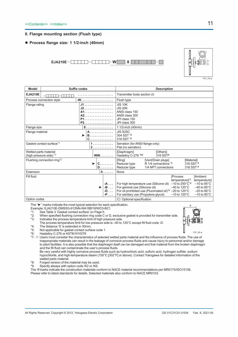
II.Flangemountingsection(Flushtype)
Processflangesize:11/2-inch(40mm)
F07_1E.ai
EJA210E W 8
Model Suffixcodes DescriptionEJA210E ..................... Transmitter body section (I)
Process connection style -W. . . . . . . . . . . . . . . . . . . Flush typeFlange rating J1 . . . . . . . . . . . . . . . . .
J2 . . . . . . . . . . . . . . . . .A1. . . . . . . . . . . . . . . . .A2. . . . . . . . . . . . . . . . .P1 . . . . . . . . . . . . . . . . .P2. . . . . . . . . . . . . . . . .
JIS 10KJIS 20KANSI class 150ANSI class 300JPI class 150JPI class 300
Flange size 8 . . . . . . . . . . . . . . . . 1 1/2-inch (40mm)Flange material
A. . . . . . . . . . . . . .B. . . . . . . . . . . . . .C. . . . . . . . . . . . . .
JIS S25C304 SST *8316 SST *8
Gasket contact surface*1 1 . . . . . . . . . . . .2 . . . . . . . . . . . .
Serration (for ANSI flange only)Flat (no serration)
Wetted parts material(high pressure side) *7 WW. . . . . . . .
[Diaphragm] [Others]Hastelloy C-276 *6# 316 SST#
Flushing connection ring*2
C. . . . . . . .D. . . . . . . .
[Ring] [Vent/Drain plugs] [Material]Reducer type R 1/4 connections *5 316 SST #Reducer type 1/4 NPT connections 316 SST #
Extension 0 . . . . . . NoneFill fluid
-A . . .-B. . .-D. . .-P . . .
[Process [Ambient temperature]*3 temperature]For high temperature use (Silicone oil) –10 to 250°C*4 –10 to 85°CFor general use (Silicone oil) –40 to 120°C –40 to 85°CFor oil prohibited use (Fluorinated oil)*9 –20 to 120°C –20 to 80°CFor sanitary use (Propylene glycol) –10 to 120°C –10 to 85°C
Option codes / Optional specification
The “” marks indicate the most typical selection for each specification.Example: EJA210E-DMS5G-912NN-WA18B1WWC0-B/*1: See Table 3 ‘Gasket contact surface’ on Page 5.*2: When specified flushing connection ring code C or D, exclusive gasket is provided for transmitter side.*3: Indicates the process temperature limit of high pressure side. The process temperature limit for low pressure side is –40 to 120°C except fill fluid code -D.*4: The distance ‘S’ is extended in 30mm.
s
F07_2E.ai*5: Not applicable for gasket contact surface code 1.*6: Hastelloy C-276 or ASTM N10276*7: Users must consider the characteristics of selected wetted parts material and the influence of process fluids. The use of
inappropriate materials can result in the leakage of corrosive process fluids and cause injury to personnel and/or damage to plant facilities. It is also possible that the diaphragm itself can be damaged and that material from the broken diaphragm and the fill fluid can contaminate the user’s process fluids.
Be very careful with highly corrosive process fluids such as hydrochloric acid, sulfuric acid, hydrogen sulfide, sodium hypochlorite, and high-temperature steam (150°C [302°F] or above). Contact Yokogawa for detailed information of the wetted parts material.
*8: Forged version of the material may be used.*9: Specify always with option code /K2 or /K6.The ‘#’marks indicate the construction materials conform to NACE material recommendations per MR0175/ISO15156.Please refer to latest standards for details. Selected materials also conform to NACE MR0103.

12
All Rights Reserved. Copyright © 2012, Yokogawa Electric Corporation
<<Contents>> <<Index>>
GS 01C31C01-01EN Feb. 8, 2021-00
II.Flangemountingsection(Extendedtype)
Processflangesize:4-inch(100mm)
F08_1E.ai
EJA210E E 4
Model Suffixcodes DescriptionEJA210E ..................... Transmitter body section (I)
Process connection style -E. . . . . . . . . . . . . . . . . . . Extended typeFlange rating J1 . . . . . . . . . . . . . . . . .
J2 . . . . . . . . . . . . . . . . .A1. . . . . . . . . . . . . . . . .A2. . . . . . . . . . . . . . . . .P1 . . . . . . . . . . . . . . . . .P2. . . . . . . . . . . . . . . . .D2. . . . . . . . . . . . . . . . .D4. . . . . . . . . . . . . . . . .
JIS 10KJIS 20KANSI class 150ANSI class 300JPI class 150JPI class 300DIN PN10/16DIN PN25/40
Flange size 4 . . . . . . . . . . . . . . . . 4-inch (100mm)Flange material
A. . . . . . . . . . . . . .B. . . . . . . . . . . . . .C. . . . . . . . . . . . . .
JIS S25C304 SST *5316 SST *5
Gasket contact surface*1 1 . . . . . . . . . . . .2 . . . . . . . . . . . .
Serration (for ANSI flange only)Flat (no serration)
Wetted parts material(high pressure side) *4 SE. . . . . . . . .
[Diaphragm] [Others] [Pipe]316L SST 316 SST 316 SST
Flushing connection ring 0 . . . . . . . . NoneExtension 1 . . . . . .
3 . . . . . .5 . . . . . .
Length (X2) = 50mmLength (X2) = 100mmLength (X2) = 150mm
Fill fluid
-A . . .-B. . .-D. . .-P . . .
[Process [Ambient temperature]*2 temperature]For high temperature use (Silicone oil) –10 to 250°C*3 –10 to 85°CFor general use (Silicone oil) –40 to 120°C –40 to 85°CFor oil prohibited use (Fluorinated oil)*6 –20 to 120°C –20 to 80°CFor sanitary use (Propylene glycol) –10 to 120°C –10 to 85°C
Option codes / Optional specification
The “” marks indicate the most typical selection for each specification.Example: EJA210E-DMS5G-912NN-EA14B1SE01-B/*1: See Table 3 ‘Gasket contact surface’ on Page 5.*2: Indicates the process temperature limit of high pressure side. The process temperature limit for low pressure side is –40 to 120°C except fill fluid code -D.*3: The distance ‘S’ is extended in 30mm.
s
F08_2E.ai
*4: Users must consider the characteristics of selected wetted parts material and the influence of process fluids. The use of inappropriate materials can result in the leakage of corrosive process fluids and cause injury to personnel and/or damage to plant facilities. It is also possible that the diaphragm itself can be damaged and that material from the broken diaphragm and the fill fluid can contaminate the user’s process fluids.
Be very careful with highly corrosive process fluids such as hydrochloric acid, sulfuric acid, hydrogen sulfide, sodium hypochlorite, and high-temperature steam (150°C [302°F] or above). Contact Yokogawa for detailed information of the wetted parts material.
*5: Forged version of the material may be used.*6: Specify always with option code /K2 or /K6.The ‘#’marks indicate the construction materials conform to NACE material recommendations per MR0175/ISO15156.Please refer to latest standards for details. Selected materials also conform to NACE MR0103.
13<<Contents>> <<Index>>
All Rights Reserved. Copyright © 2012, Yokogawa Electric Corporation GS 01C31C01-01EN Feb. 8, 2021-00
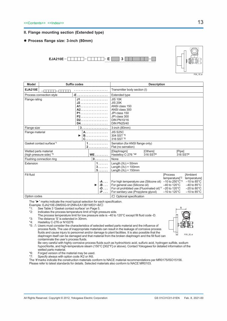
II.Flangemountingsection(Extendedtype)
Processflangesize:3-inch(80mm)
F09_1E.ai
EJA210E E 3
Model Suffixcodes DescriptionEJA210E ..................... Transmitter body section (I)
Process connection style -E. . . . . . . . . . . . . . . . . . . Extended typeFlange rating J1 . . . . . . . . . . . . . . . . .
J2 . . . . . . . . . . . . . . . . .A1. . . . . . . . . . . . . . . . .A2. . . . . . . . . . . . . . . . .P1 . . . . . . . . . . . . . . . . .P2. . . . . . . . . . . . . . . . .D2. . . . . . . . . . . . . . . . .D4. . . . . . . . . . . . . . . . .
JIS 10KJIS 20KANSI class 150ANSI class 300JPI class 150JPI class 300DIN PN10/16DIN PN25/40
Flange size 3 . . . . . . . . . . . . . . . . 3-inch (80mm)Flange material
A. . . . . . . . . . . . . .B. . . . . . . . . . . . . .C. . . . . . . . . . . . . .
JIS S25C304 SST *6316 SST *6
Gasket contact surface*1 1 . . . . . . . . . . . .2 . . . . . . . . . . . .
Serration (for ANSI flange only)Flat (no serration)
Wetted parts material(high pressure side) *5 WE. . . . . . . .
[Diaphragm] [Others] [Pipe]Hastelloy C-276 *4# 316 SST# 316 SST#
Flushing connection ring 0 . . . . . . . . NoneExtension 1 . . . . . .
3 . . . . . .5 . . . . . .
Length (X2) = 50mmLength (X2) = 100mmLength (X2) = 150mm
Fill fluid
-A . . .-B. . .-D. . .-P . . .
[Process [Ambient temperature]*2 temperature]For high temperature use (Silicone oil) –10 to 250°C*3 –10 to 85°CFor general use (Silicone oil) –40 to 120°C –40 to 85°CFor oil prohibited use (Fluorinated oil)*7 –20 to 120°C –20 to 80°CFor sanitary use (Propylene glycol) –10 to 120°C –10 to 85°C
Option codes / Optional specification
The “” marks indicate the most typical selection for each specification.Example: EJA210E-DMS5G-912NN-EA13B1WE01-B/*1: See Table 3 ‘Gasket contact surface’ on Page 5.*2: Indicates the process temperature limit of high pressure side. The process temperature limit for low pressure side is –40 to 120°C except fill fluid code -D.*3: The distance ‘S’ is extended in 30mm.
s
F09_2E.ai
*4: Hastelloy C-276 or N10276*5: Users must consider the characteristics of selected wetted parts material and the influence of
process fluids. The use of inappropriate materials can result in the leakage of corrosive process fluids and cause injury to personnel and/or damage to plant facilities. It is also possible that the diaphragm itself can be damaged and that material from the broken diaphragm and the fill fluid can contaminate the user’s process fluids.
Be very careful with highly corrosive process fluids such as hydrochloric acid, sulfuric acid, hydrogen sulfide, sodium hypochlorite, and high-temperature steam (150°C [302°F] or above). Contact Yokogawa for detailed information of the wetted parts material.
*6: Forged version of the material may be used.*7: Specify always with option code /K2 or /K6.The ‘#’marks indicate the construction materials conform to NACE material recommendations per MR0175/ISO15156.Please refer to latest standards for details. Selected materials also conform to NACE MR0103.
14
All Rights Reserved. Copyright © 2012, Yokogawa Electric Corporation
<<Contents>> <<Index>>
GS 01C31C01-01EN July 1, 2021-00
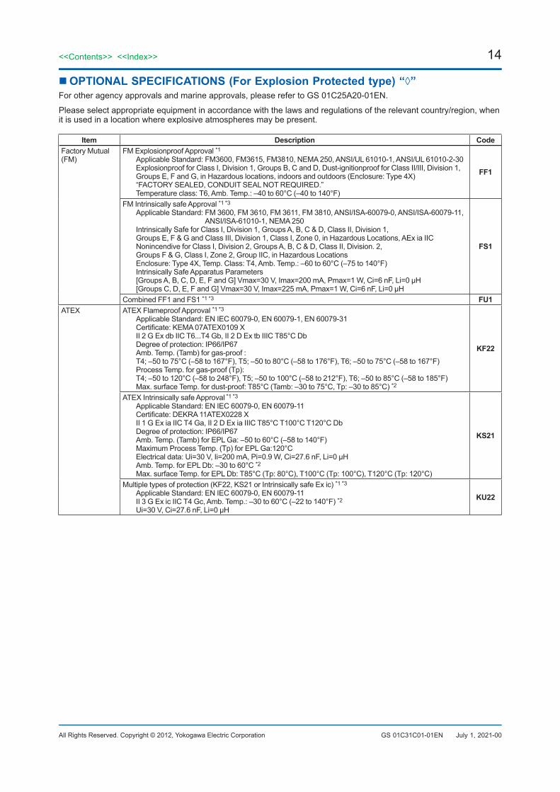
OPTIONALSPECIFICATIONS(ForExplosionProtectedtype)“◊”For other agency approvals and marine approvals, please refer to GS 01C25A20-01EN.
Please select appropriate equipment in accordance with the laws and regulations of the relevant country/region, when it is used in a location where explosive atmospheres may be present.
Item Description CodeFactory Mutual(FM)
FM Explosionproof Approval *1Applicable Standard: FM3600, FM3615, FM3810, NEMA 250, ANSI/UL 61010-1, ANSI/UL 61010-2-30Explosionproof for Class I, Division 1, Groups B, C and D, Dust-ignitionproof for Class II/III, Division 1,Groups E, F and G, in Hazardous locations, indoors and outdoors (Enclosure: Type 4X)“FACTORY SEALED, CONDUIT SEAL NOT REQUIRED.”Temperature class: T6, Amb. Temp.: –40 to 60°C (–40 to 140°F)
FF1
FM Intrinsically safe Approval *1 *3
Applicable Standard: FM 3600, FM 3610, FM 3611, FM 3810, ANSI/ISA-60079-0, ANSI/ISA-60079-11, ANSI/ISA-61010-1, NEMA 250
Intrinsically Safe for Class I, Division 1, Groups A, B, C & D, Class II, Division 1,Groups E, F & G and Class III, Division 1, Class I, Zone 0, in Hazardous Locations, AEx ia IICNonincendive for Class I, Division 2, Groups A, B, C & D, Class II, Division. 2,Groups F & G, Class I, Zone 2, Group IIC, in Hazardous LocationsEnclosure: Type 4X, Temp. Class: T4, Amb. Temp.: –60 to 60°C (–75 to 140°F)Intrinsically Safe Apparatus Parameters[Groups A, B, C, D, E, F and G] Vmax=30 V, Imax=200 mA, Pmax=1 W, Ci=6 nF, Li=0 µH[Groups C, D, E, F and G] Vmax=30 V, Imax=225 mA, Pmax=1 W, Ci=6 nF, Li=0 µH
FS1
Combined FF1 and FS1 *1 *3 FU1ATEX ATEX Flameproof Approval *1 *3
Applicable Standard: EN IEC 60079-0, EN 60079-1, EN 60079-31Certificate: KEMA 07ATEX0109 XII 2 G Ex db IIC T6...T4 Gb, II 2 D Ex tb IIIC T85°C DbDegree of protection: IP66/IP67Amb. Temp. (Tamb) for gas-proof :T4; –50 to 75°C (–58 to 167°F), T5; –50 to 80°C (–58 to 176°F), T6; –50 to 75°C (–58 to 167°F) Process Temp. for gas-proof (Tp):T4; –50 to 120°C (–58 to 248°F), T5; –50 to 100°C (–58 to 212°F), T6; –50 to 85°C (–58 to 185°F)Max. surface Temp. for dust-proof: T85°C (Tamb: –30 to 75°C, Tp: –30 to 85°C) *2
KF22
ATEX Intrinsically safe Approval *1 *3
Applicable Standard: EN IEC 60079-0, EN 60079-11Certificate: DEKRA 11ATEX0228 XII 1 G Ex ia IIC T4 Ga, II 2 D Ex ia IIIC T85°C T100°C T120°C DbDegree of protection: IP66/IP67Amb. Temp. (Tamb) for EPL Ga: –50 to 60°C (–58 to 140°F) Maximum Process Temp. (Tp) for EPL Ga:120°CElectrical data: Ui=30 V, Ii=200 mA, Pi=0.9 W, Ci=27.6 nF, Li=0 µHAmb. Temp. for EPL Db: –30 to 60°C *2Max. surface Temp. for EPL Db: T85°C (Tp: 80°C), T100°C (Tp: 100°C), T120°C (Tp: 120°C)
KS21
Multiple types of protection (KF22, KS21 or Intrinsically safe Ex ic) *1 *3
Applicable Standard: EN IEC 60079-0, EN 60079-11 II 3 G Ex ic IIC T4 Gc, Amb. Temp.: –30 to 60°C (–22 to 140°F) *2Ui=30 V, Ci=27.6 nF, Li=0 μH
KU22
15<<Contents>> <<Index>>
All Rights Reserved. Copyright © 2012, Yokogawa Electric Corporation GS 01C31C01-01EN Feb. 1, 2022-00
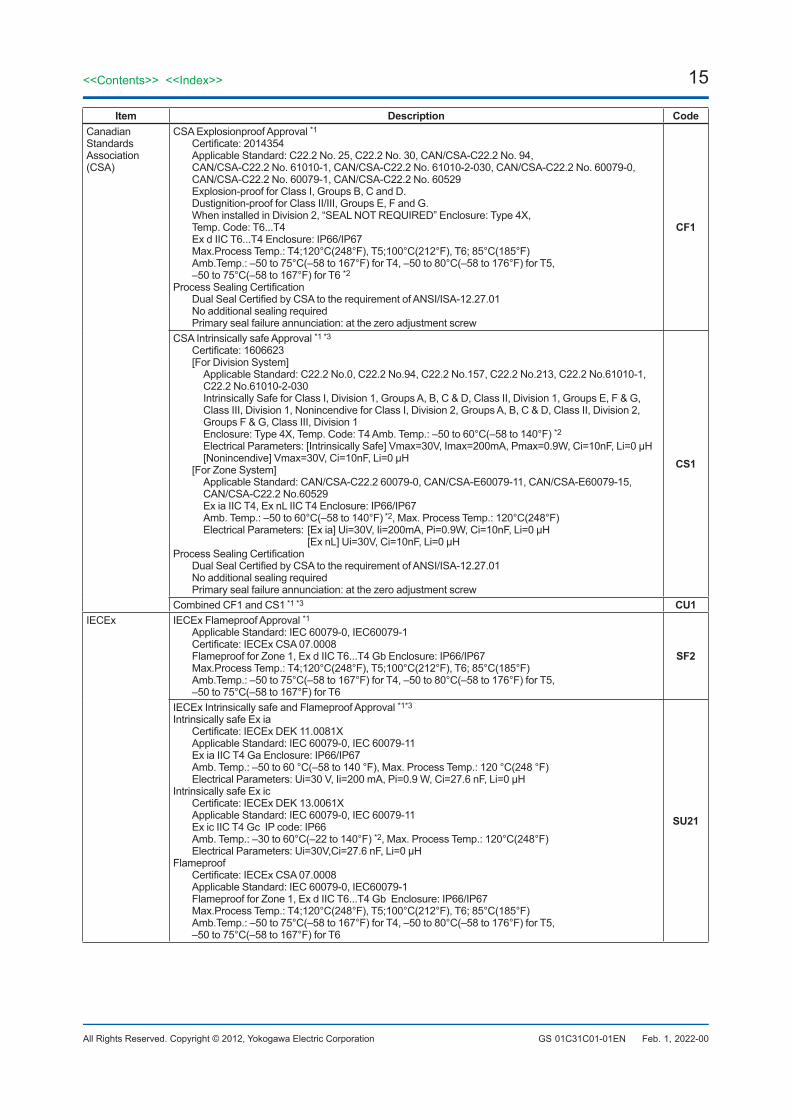
Item Description CodeCanadianStandardsAssociation(CSA)
CSA Explosionproof Approval *1Certificate: 2014354Applicable Standard: C22.2 No. 25, C22.2 No. 30, CAN/CSA-C22.2 No. 94, CAN/CSA-C22.2 No. 61010-1, CAN/CSA-C22.2 No. 61010-2-030, CAN/CSA-C22.2 No. 60079-0, CAN/CSA-C22.2 No. 60079-1, CAN/CSA-C22.2 No. 60529Explosion-proof for Class I, Groups B, C and D.Dustignition-proof for Class II/III, Groups E, F and G.When installed in Division 2, “SEAL NOT REQUIRED” Enclosure: Type 4X, Temp. Code: T6...T4Ex d IIC T6...T4 Enclosure: IP66/IP67Max.Process Temp.: T4;120°C(248°F), T5;100°C(212°F), T6; 85°C(185°F)Amb.Temp.: –50 to 75°C(–58 to 167°F) for T4, –50 to 80°C(–58 to 176°F) for T5, –50 to 75°C(–58 to 167°F) for T6 *2
Process Sealing CertificationDual Seal Certified by CSA to the requirement of ANSI/ISA-12.27.01No additional sealing requiredPrimary seal failure annunciation: at the zero adjustment screw
CF1
CSA Intrinsically safe Approval *1 *3
Certificate: 1606623[For Division System]
Applicable Standard: C22.2 No.0, C22.2 No.94, C22.2 No.157, C22.2 No.213, C22.2 No.61010-1, C22.2 No.61010-2-030Intrinsically Safe for Class I, Division 1, Groups A, B, C & D, Class II, Division 1, Groups E, F & G,Class III, Division 1, Nonincendive for Class I, Division 2, Groups A, B, C & D, Class II, Division 2,Groups F & G, Class III, Division 1Enclosure: Type 4X, Temp. Code: T4 Amb. Temp.: –50 to 60°C(–58 to 140°F) *2Electrical Parameters: [Intrinsically Safe] Vmax=30V, Imax=200mA, Pmax=0.9W, Ci=10nF, Li=0 µH[Nonincendive] Vmax=30V, Ci=10nF, Li=0 µH
[For Zone System]Applicable Standard: CAN/CSA-C22.2 60079-0, CAN/CSA-E60079-11, CAN/CSA-E60079-15, CAN/CSA-C22.2 No.60529Ex ia IIC T4, Ex nL IIC T4 Enclosure: IP66/IP67Amb. Temp.: –50 to 60°C(–58 to 140°F) *2, Max. Process Temp.: 120°C(248°F)Electrical Parameters: [Ex ia] Ui=30V, Ii=200mA, Pi=0.9W, Ci=10nF, Li=0 µH [Ex nL] Ui=30V, Ci=10nF, Li=0 µH
Process Sealing CertificationDual Seal Certified by CSA to the requirement of ANSI/ISA-12.27.01No additional sealing requiredPrimary seal failure annunciation: at the zero adjustment screw
CS1
Combined CF1 and CS1 *1 *3 CU1IECEx IECEx Flameproof Approval *1
Applicable Standard: IEC 60079-0, IEC60079-1Certificate: IECEx CSA 07.0008Flameproof for Zone 1, Ex d IIC T6...T4 Gb Enclosure: IP66/IP67Max.Process Temp.: T4;120°C(248°F), T5;100°C(212°F), T6; 85°C(185°F)Amb.Temp.: –50 to 75°C(–58 to 167°F) for T4, –50 to 80°C(–58 to 176°F) for T5,–50 to 75°C(–58 to 167°F) for T6
SF2
IECEx Intrinsically safe and Flameproof Approval *1*3
Intrinsically safe Ex iaCertificate: IECEx DEK 11.0081X Applicable Standard: IEC 60079-0, IEC 60079-11Ex ia IIC T4 Ga Enclosure: IP66/IP67Amb. Temp.: –50 to 60 °C(–58 to 140 °F), Max. Process Temp.: 120 °C(248 °F)Electrical Parameters: Ui=30 V, Ii=200 mA, Pi=0.9 W, Ci=27.6 nF, Li=0 μH
Intrinsically safe Ex icCertificate: IECEx DEK 13.0061X Applicable Standard: IEC 60079-0, IEC 60079-11Ex ic IIC T4 Gc IP code: IP66Amb. Temp.: –30 to 60°C(–22 to 140°F) *2, Max. Process Temp.: 120°C(248°F)Electrical Parameters: Ui=30V,Ci=27.6 nF, Li=0 μH
FlameproofCertificate: IECEx CSA 07.0008Applicable Standard: IEC 60079-0, IEC60079-1Flameproof for Zone 1, Ex d IIC T6...T4 Gb Enclosure: IP66/IP67Max.Process Temp.: T4;120°C(248°F), T5;100°C(212°F), T6; 85°C(185°F)Amb.Temp.: –50 to 75°C(–58 to 167°F) for T4, –50 to 80°C(–58 to 176°F) for T5,–50 to 75°C(–58 to 167°F) for T6
SU21
16
All Rights Reserved. Copyright © 2012, Yokogawa Electric Corporation
<<Contents>> <<Index>>
GS 01C31C01-01EN
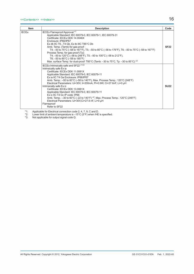
Item Description CodeIECEx IECEx Flameproof Approval *1
Applicable Standard: IEC 60079-0, IEC 60079-1, IEC 60079-31Certificate: IECEx DEK 14.0046XEnclosure: IP66/IP67Ex db IIC T6...T4 Gb, Ex tb IIIC T85°C DbAmb. Temp. (Tamb) for gas-proof :
T4; –50 to 75°C (–58 to 167°F), T5; –50 to 80°C (–58 to 176°F), T6; –50 to 75°C (–58 to 167°F)Process Temp. for gas-proof (Tp):
T4; –50 to 120°C (–58 to 248°F), T5; –50 to 100°C (–58 to 212°F),T6; –50 to 85°C (–58 to 185°F)
Max. surface Temp. for dust-proof: T85°C (Tamb: –30 to 75°C, Tp: –30 to 85°C) *2
SF22
IECEx Intrinsically safe and SF22 *1*3
Intrinsically safe Ex iaCertificate: IECEx DEK 11.0081XApplicable Standard: IEC 60079-0, IEC 60079-11Ex ia IIC T4 Ga Enclosure: IP66/IP67Amb. Temp.: –50 to 60°C (–58 to 140°F), Max. Process Temp.: 120°C (248°F)Electrical Parameters: Ui=30V, Ii=200mA, Pi=0.9W, Ci=27.6nF, Li=0 μH
Intrinsically safe Ex icCertificate: IECEx DEK 13.0061XApplicable Standard: IEC 60079-0, IEC 60079-11Ex ic IIC T4 Gc IP code: IP66Amb. Temp.: –30 to 60°C (–22 to 140°F) *2, Max. Process Temp.: 120°C (248°F)Electrical Parameters: Ui=30V,Ci=27.6 nF, Li=0 μH
FlameproofRefer to SF22
SU22
*1: Applicable for Electrical connection code 2, 4, 7, 9, C and D.*2: Lower limit of ambient temperature is –15°C (5°F) when /HE is specified.*3: Not applicable for output signal code Q.
Feb. 1, 2022-00
17<<Contents>> <<Index>>
All Rights Reserved. Copyright © 2012, Yokogawa Electric Corporation GS 01C31C01-01EN Nov. 20, 2019-00
OPTIONALSPECIFICATIONSItem Description Code
Painting Color change Amplifier cover only *1 PAmplifier cover and terminal cover, Munsell 7.5 R4/14 PR
Coating change Anti-corrosion coating *2 X2316 SST exterior parts 316 SST zero-adjustment screw and setscrews *3 HCFluoro-rubber O-ring All O-rings of amplifier housing. Lower limit of ambient temperature: –15°C (5°F) HELightning protector Transmitter power supply voltage: 10.5 to 32 V DC (10.5 to 30 V DC for intrinsically safe type.)
Allowable current: Max. 6000 A (1×40 µs), Repeating 1000 A (1×40 µs) 100 timesApplicable Standards: IEC 61000-4-4, IEC 61000-4-5
A
Oil-prohibited use Degrease cleansing treatment K1Degrease cleansing with fluorinated oil filled capsule. *4Operating temperature –20 to 80°C K2
Oil-prohibited use with dehydrating treatment
Degrease cleansing and dehydrating treatment K5Degrease cleansing and dehydrating treatment with fluorinated oil filled capsule. *4
Operating temperature –20 to 80°C K6
Calibration units *5 P calibration (psi unit)(See Table for Span and Range Limits.)
D1bar calibration (bar unit) D3M calibration (kgf/cm2 unit) D4
Teflon film *6 *7 Diaphragm protection from sticky process fluid by FEP Teflon film attached with fluorinated oil.Operation range: 20 to 150°C, 0 to 2 MPa (Not applicable for vacuum service). TF1
Output limits and failure operation *8
Failure alarm down-scale: Output status at CPU failure and hardware error is −5%, 3.2mA DC or less for 4 to 20 mA output type, and −5%, 0.8V DC or less for 1 to 5 V output type. C1
NAMUR NE43 Compliant Output signal limits: 3.8 mA to 20.5 mA *18
Failure alarm down-scale: Output status at CPUfailure and hardware error is −5%, 3.2 mA DC or less. C2
Failure alarm up-scale: Output status at CPUfailure and hardware error is 110%, 21.6 mA or more. C3
Gold-plated diaphragm *9 Inside of isolating diaphragms (fill fluid side) are gold plated, effective for hydrogen permeation. A1
Wired tag plate 316 SST tag plate wired onto transmitter (Tag No.: Maximum. 16 characters.) N4Data configuration at factory*10
Data configuration for HART communication type Software damping, Descriptor, Message CA
Data configuration for BRAIN communication type Software damping CBMaterialcertificate
For Flush type High Pressure side: Process flange, Block *11 Low Pressure side: Cover flange M0W
High Pressure side: Process flange, Block *12 Low Pressure side: Cover flange, Process connector M1W
High Pressure side: Process flange, Block, Ring *11 *13 Low Pressure side: Cover flange M3W
High Pressure side: Process flange, Block, Ring *12 *13 Low Pressure side: Cover flange, Process connector M4W
For Extended type
High Pressure side: Process flange, Block, Pipe, Base *11 Low Pressure side: Cover flange M0E
High Pressure side: Process flange, Block, Pipe, Base *12
Low Pressure side: Cover flange, Process connector M1E
Pressure test/Leak test certificate *14*15
[Flange rating] [Test pressure]JIS 10K 2 MPa (290 psi)
Nitrogen Gas *17
Retention time: one minute
T51JIS 20K 5 MPa (720 psi) T54ANSI/JPI Class 150 3 MPa (430 psi) T52ANSI/JPI Class 300 8 MPa (1160 psi) *6 T56ANSI/JPI Class 300 7 MPa (1000 psi) *16 T55
Parameter list *19 List of setting and adjustment parameters YP
18
All Rights Reserved. Copyright © 2012, Yokogawa Electric Corporation
<<Contents>> <<Index>>
GS 01C31C01-01EN Mar. 30, 2020-00
*1: Not applicable for amplifier housing code 2 and 3.*2: Not applicable with color change option. Not applicable for amplifier housing code 2.*3: 316 or 316L SST. The specification is included in amplifier code 2.*4: Applicable only when fill fluid code -D is specified.*5: The unit of MWP (Max. working pressure) on the name plate of a housing is the same unit as specified by option code D1,
D3, and D4.*6: Applicable for flush type (process connection style code W.)*7: Applicable for flushing connection ring code 0.*8: Applicable for output signal code D and J. The hardware error indicates faulty amplifier or capsule.*9: Applicable for wetted parts material code SW, SE, WW, WE, and HW. Consult Yokogawa in case gold-plated diaphragm is required for low pressure side.*10: Also see ‘Ordering Information.’*11: Applicable for Low Pressure Side Process connection code 0 and 5.*12: Applicable for Low Pressure Side Process connection code 1, 2, 3, and 4.*13: Applicable for flushing connection ring code A, B, C, and D.*14: The unit on the certificate is always MPa regardless of selection of option code D1, D3, or D4.*15: A flushing connection ring will not be applied when conducting the pressure test or leak test.*16: Applicable for extended type (process connection style code E.)*17: Dry nitrogen gas is used for oil-prohibited use (option code K1, K2, K5, and K6.)*18: The 1 to 5 V voltage output corresponding to 4 to 20 mA current output is applied to output signal code Q which is non-
compliant to NAMUR NE43.*19: Applicable for output signal code D and J.
19<<Contents>> <<Index>>
All Rights Reserved. Copyright © 2012, Yokogawa Electric Corporation GS 01C31C01-01EN Nov. 20, 2019-00
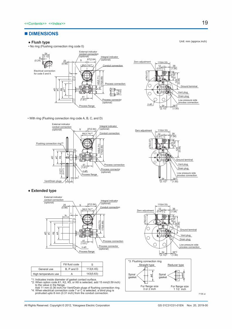
DIMENSIONS
*1: Indicates inside diameter of gasket contact surface.*2: When option code K1, K2, K5, or K6 is selected, add 15 mm(0.59 inch)
to the value in the flange.Add 11 mm (0.36 inch) for Vent/Drain plugs of flushing connection ring.
*4: When electrical connection code 7 or C is selected, a blind plug is protruded upto 8 mm (0.31 inch) from the conduit connection.
Fill fluid code
B, P and D
143(5.63)
113(4.45)
A
General use
High temperature use
S
F10E.ai
ød
*3: Flushing connection ring
For flange size3 or 2 inch
Spiralgasket
Spiralgasket ø4
4
For flange size1 1/2 inch
Straight type Reducer type
Unit: mm (approx.inch) Flush type
54(2.13)6
(0.24)
Electrical connectionfor code 5 and 9.
38*2(1.50)
54(2.13)
129
(5.0
8)
ø70
(2.7
6)
ø78(
3.07
)
110(4.33)39
(1.54)12
(0.47)95(3.74)*4
41(1.61)
S 67(2.64)25(0.98)
øD øC øg ød*1
175(
6.89
)14
5(5.
71)
Ground terminal
Zero adjustmentConduit connection
Integral indicator(optional)
External indicatorconduit connection(optional)
n-øh
Vent plug
Low pressure sideprocess connection
Drain plug
Process flange
Process connection
Process connector(optional)
t
• No ring (Flushing connection ring code 0)
• With ring (Flushing connection ring code A, B, C, and D)
Extended type
j
S
112*
2
(4.4
1)
tk
øD øC øg
145(
5.71
)17
5(6.
89)
67(2.64)
41(1.61)
95(3.74)*4 12(0.47)
39(1.54)
110(4.33)
ø78(
3.07
)
ø70
(2.7
6)12
9(5
.08)
54(2.13)
38*2
(1.50)
Flushing connection ring*3
Vent/Drain plugs
n-øh
External indicatorconduit connection(optional)
Integral indicator(optional)
Conduit connectionZero adjustment
Ground terminal
Process connector(optional)
Process connection
Process flange
Drain plug
Low pressure sideprocess connection
Vent plug
38*2
(1.50)54
(2.13)
129
(5.0
8)
ø70
(2.7
6)
ø78(
3.07
)
110(4.33)
39(1.54)
12(0.47)
95(3.74)*4
41(1.61)
S 67(2.64)25(0.98)
t
175(
6.89
)14
5(5.
71)
X2
øAøgøCøD
Ground terminal
Zero adjustmentConduit connection
Integral indicator(optional)
External indicatorconduit connection(optional)
n-øh
Vent plug
Low pressure sideprocess connection
Drain plug
Process flange
Process connection
Process connector(optional)
41.3
(1.6
3)
20
All Rights Reserved. Copyright © 2012, Yokogawa Electric Corporation
<<Contents>> <<Index>>
GS 01C31C01-01EN Oct. 24, 2014-00
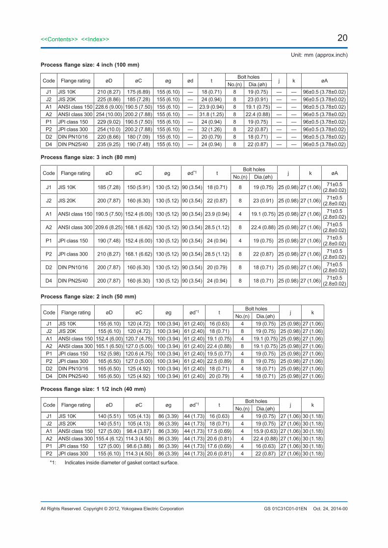
Unit: mm (approx.inch)
Processflangesize:4inch(100mm)
Code Flange rating øD øC øg ød tBolt holes
j k øANo.(n) Dia.(øh)
J1 JIS 10K 210 (8.27) 175 (6.89) 155 (6.10) — 18 (0.71) 8 19 (0.75) — — 96±0.5 (3.78±0.02)J2 JIS 20K 225 (8.86) 185 (7.28) 155 (6.10) — 24 (0.94) 8 23 (0.91) — — 96±0.5 (3.78±0.02)A1 ANSI class 150 228.6 (9.00) 190.5 (7.50) 155 (6.10) — 23.9 (0.94) 8 19.1 (0.75) — — 96±0.5 (3.78±0.02)A2 ANSI class 300 254 (10.00) 200.2 (7.88) 155 (6.10) — 31.8 (1.25) 8 22.4 (0.88) — — 96±0.5 (3.78±0.02)P1 JPI class 150 229 (9.02) 190.5 (7.50) 155 (6.10) — 24 (0.94) 8 19 (0.75) — — 96±0.5 (3.78±0.02)P2 JPI class 300 254 (10.0) 200.2 (7.88) 155 (6.10) — 32 (1.26) 8 22 (0.87) — — 96±0.5 (3.78±0.02)D2 DIN PN10/16 220 (8.66) 180 (7.09) 155 (6.10) — 20 (0.79) 8 18 (0.71) — — 96±0.5 (3.78±0.02)D4 DIN PN25/40 235 (9.25) 190 (7.48) 155 (6.10) — 24 (0.94) 8 22 (0.87) — — 96±0.5 (3.78±0.02)
Processflangesize:3inch(80mm)
Code Flange rating øD øC øg ød*1 tBolt holes
j k øANo.(n) Dia.(øh)
J1 JIS 10K 185 (7.28) 150 (5.91) 130 (5.12) 90 (3.54) 18 (0.71) 8 19 (0.75) 25 (0.98) 27 (1.06) 71±0.5 (2.8±0.02)
J2 JIS 20K 200 (7.87) 160 (6.30) 130 (5.12) 90 (3.54) 22 (0.87) 8 23 (0.91) 25 (0.98) 27 (1.06) 71±0.5 (2.8±0.02)
A1 ANSI class 150 190.5 (7.50) 152.4 (6.00) 130 (5.12) 90 (3.54) 23.9 (0.94) 4 19.1 (0.75) 25 (0.98) 27 (1.06) 71±0.5 (2.8±0.02)
A2 ANSI class 300 209.6 (8.25) 168.1 (6.62) 130 (5.12) 90 (3.54) 28.5 (1.12) 8 22.4 (0.88) 25 (0.98) 27 (1.06) 71±0.5 (2.8±0.02)
P1 JPI class 150 190 (7.48) 152.4 (6.00) 130 (5.12) 90 (3.54) 24 (0.94) 4 19 (0.75) 25 (0.98) 27 (1.06) 71±0.5 (2.8±0.02)
P2 JPI class 300 210 (8.27) 168.1 (6.62) 130 (5.12) 90 (3.54) 28.5 (1.12) 8 22 (0.87) 25 (0.98) 27 (1.06) 71±0.5 (2.8±0.02)
D2 DIN PN10/16 200 (7.87) 160 (6.30) 130 (5.12) 90 (3.54) 20 (0.79) 8 18 (0.71) 25 (0.98) 27 (1.06) 71±0.5 (2.8±0.02)
D4 DIN PN25/40 200 (7.87) 160 (6.30) 130 (5.12) 90 (3.54) 24 (0.94) 8 18 (0.71) 25 (0.98) 27 (1.06) 71±0.5 (2.8±0.02)
Processflangesize:2inch(50mm)
Code Flange rating øD øC øg ød*1 tBolt holes
j kNo.(n) Dia.(øh)
J1 JIS 10K 155 (6.10) 120 (4.72) 100 (3.94) 61 (2.40) 16 (0.63) 4 19 (0.75) 25 (0.98) 27 (1.06)J2 JIS 20K 155 (6.10) 120 (4.72) 100 (3.94) 61 (2.40) 18 (0.71) 8 19 (0.75) 25 (0.98) 27 (1.06)A1 ANSI class 150 152.4 (6.00) 120.7 (4.75) 100 (3.94) 61 (2.40) 19.1 (0.75) 4 19.1 (0.75) 25 (0.98) 27 (1.06)A2 ANSI class 300 165.1 (6.50) 127.0 (5.00) 100 (3.94) 61 (2.40) 22.4 (0.88) 8 19.1 (0.75) 25 (0.98) 27 (1.06)P1 JPI class 150 152 (5.98) 120.6 (4.75) 100 (3.94) 61 (2.40) 19.5 (0.77) 4 19 (0.75) 25 (0.98) 27 (1.06)P2 JPI class 300 165 (6.50) 127.0 (5.00) 100 (3.94) 61 (2.40) 22.5 (0.89) 8 19 (0.75) 25 (0.98) 27 (1.06)D2 DIN PN10/16 165 (6.50) 125 (4.92) 100 (3.94) 61 (2.40) 18 (0.71) 4 18 (0.71) 25 (0.98) 27 (1.06)D4 DIN PN25/40 165 (6.50) 125 (4.92) 100 (3.94) 61 (2.40) 20 (0.79) 4 18 (0.71) 25 (0.98) 27 (1.06)
Processflangesize:11/2inch(40mm)
Code Flange rating øD øC øg ød*1 tBolt holes
j kNo.(n) Dia.(øh)
J1 JIS 10K 140 (5.51) 105 (4.13) 86 (3.39) 44 (1.73) 16 (0.63) 4 19 (0.75) 27 (1.06) 30 (1.18)J2 JIS 20K 140 (5.51) 105 (4.13) 86 (3.39) 44 (1.73) 18 (0.71) 4 19 (0.75) 27 (1.06) 30 (1.18)A1 ANSI class 150 127 (5.00) 98.4 (3.87) 86 (3.39) 44 (1.73) 17.5 (0.69) 4 15.9 (0.63) 27 (1.06) 30 (1.18)A2 ANSI class 300 155.4 (6.12) 114.3 (4.50) 86 (3.39) 44 (1.73) 20.6 (0.81) 4 22.4 (0.88) 27 (1.06) 30 (1.18)P1 JPI class 150 127 (5.00) 98.6 (3.88) 86 (3.39) 44 (1.73) 17.6 (0.69) 4 16 (0.63) 27 (1.06) 30 (1.18)P2 JPI class 300 155 (6.10) 114.3 (4.50) 86 (3.39) 44 (1.73) 20.6 (0.81) 4 22 (0.87) 27 (1.06) 30 (1.18)
*1: Indicates inside diameter of gasket contact surface.
21<<Contents>> <<Index>>
All Rights Reserved. Copyright © 2012, Yokogawa Electric Corporation GS 01C31C01-01EN Oct. 24, 2014-00
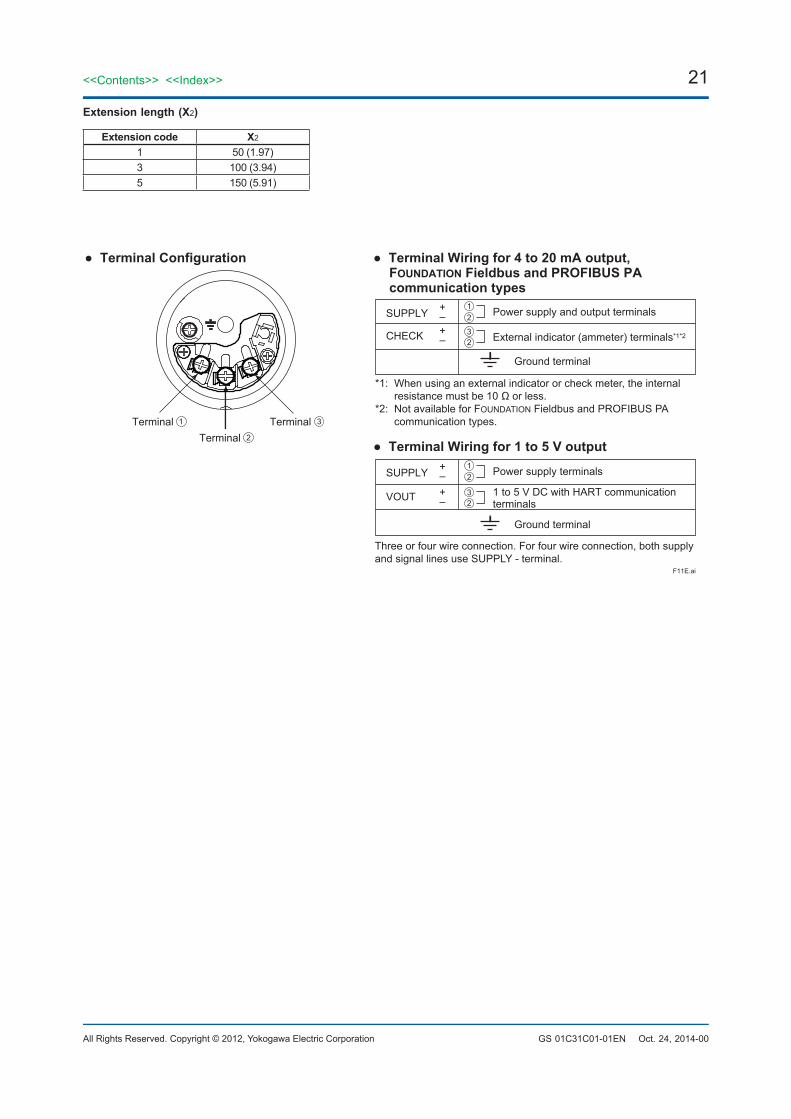
Extensionlength(X2)
Extensioncode X2
1 50 (1.97)3 100 (3.94)5 150 (5.91)
F11E.ai
SUPPLY
CHECK
+–+–
Power supply and output terminals
External indicator (ammeter) terminals*1*2
*1: When using an external indicator or check meter, the internal resistance must be 10 Ω or less. *2: Not available for FOUNDATION Fieldbus and PROFIBUS PA communication types.
Terminal Configuration
Ground terminal
1Terminal
12
23
SUPPLY
VOUT
+–+–
Power supply terminals
Terminal Wiring for 1 to 5 V output
Ground terminal
12
23
2Terminal 3Terminal
1 to 5 V DC with HART communication terminals
Terminal Wiring for 4 to 20 mA output, FOUNDATION Fieldbus and PROFIBUS PA communication types
Three or four wire connection. For four wire connection, both supply and signal lines use SUPPLY - terminal.
22
All Rights Reserved. Copyright © 2012, Yokogawa Electric Corporation
<<Contents>> <<Index>>
GS 01C31C01-01ENSubject to change without notice.
April 10, 2018-00
<OrderingInformation>“◊”Specify the following when ordering1. Model, suffix codes, and option codes2. Calibration range and units:
1) Calibration range can be specified with range value specifications up to 5 digits (excluding any decimal point) for low or high range limits within the range of -32000 to 32000. When reverse range is designated, specify LRV as greater than URV. When square root output mode is specified, LRV must be “0(zero)”.
2) Specify only one unit from the table, ‘Factory setting.’
3. Display scale and units (for transmitters equipped with the integral indicator only)
Specify either 0 to 100 % or ‘Range and Unit’ for engineering units scale:
Scale range can be specified with range limit specifications up to 5 digits (excluding any decimal point) for low or high range limits within the range of -32000 to 32000. Unit display consists of 6-digit, therefore, if the specified scaling unit excluding ‘/’ is longer than 6-characters , the first 6 characters will be displayed on the unit display.
4. HART PROTOCOL When output signal code is “J”, specify the HART
protocol revision “5” or “7”.5. TAG NO (if required) Specified characters (up to 16 characters for
BRAIN, 22 characters for HART, or 16 characters for /N4 tag) are engraved on the stainless steel tag plate fixed on the housing.
6. SOFTWARE TAG (for HART only. if required) Specified characters (up to 32 characters) are set
as “Tag” (the first 8 characters) and “Long tag”*1 (32 characters) in the amplifier memory. Use alphanumeric capital letters.
When the “SOFTWARE TAG” is not specified, specified “TAG NO” is set as “Tag” (the first 8 characters) and “Long tag”*1 (22 characters) in the amplifier memory.*1: applicable only when HART 7 is selected.
7. Other factory configurations (if required) Specifying option code CA or CB will allow further configuration at factory. Following are configurable items and setting range.
[/CA : For HART communication type]1) Descriptor (up to 16 characters)2) Message (up to 30 characters)3) Software damping (0.00 to 100.00 s)
[/CB : For BRAIN communication type]1) Software damping (0.00 to 100.00 s)
<FactorySetting>
Tag number As specified in orderSoftware damping *1 ‘2.00 s’ or as specified in order
Calibration range lower range value As specified in order
Calibration range upper range value
As specified in order
Calibration range units
Selected from mmH2O, mmH2O(68°F), mmAq*2, mmWG*2, mmHg, Pa, hPa*2, kPa, MPa, mbar, bar, gf/cm2, kgf/cm2, inH2O, inH2O(68°F), inHg, ftH2O, ftH2O(68°F) or psi. (Only one unit can be specified.)
Display settingDesignated differential pressure value specified in order. (% or user scaled value.)
Static pressure display range
‘0 to 25 MPa’ for M and H capsule, absolute value.Measuring low pressure side.
*1: To specify these items at factory, option code /CA or /CB is required.
*2: Not available for HART protocol type.
<MaterialCrossReference>
ASTM JIS316 SUS316F316 SUSF316316L SUS316LF316L SUSF316L304 SUS304F304 SUSF304660 SUH660B7 SNB7CF-8M SCS14A
<InformationonEUWEEEDirective>EU WEEE (Waste Electrical and Electronic Equipment) Directive is only valid in the EU.This instrument is intended to be sold and used only as a part of equipment which is excluded from WEEE Directive, such as large-scale stationary industrial tools, a large-scale fixed installation and so on, and, therefore, subjected to the exclusion from the scope of the WEEE Directive. The instrument should be disposed of in accordance with local and national legislation/regulations.
Related Documents