Eindhoven University of Technology MASTER Multicast DNS in wireless ad-hoc networks of low-resource devices Lu, Y. Award date: 2012 Disclaimer This document contains a student thesis (bachelor's or master's), as authored by a student at Eindhoven University of Technology. Student theses are made available in the TU/e repository upon obtaining the required degree. The grade received is not published on the document as presented in the repository. The required complexity or quality of research of student theses may vary by program, and the required minimum study period may vary in duration. General rights Copyright and moral rights for the publications made accessible in the public portal are retained by the authors and/or other copyright owners and it is a condition of accessing publications that users recognise and abide by the legal requirements associated with these rights. • Users may download and print one copy of any publication from the public portal for the purpose of private study or research. • You may not further distribute the material or use it for any profit-making activity or commercial gain Take down policy If you believe that this document breaches copyright please contact us providing details, and we will remove access to the work immediately and investigate your claim. Download date: 28. May. 2018

Welcome message from author
This document is posted to help you gain knowledge. Please leave a comment to let me know what you think about it! Share it to your friends and learn new things together.
Transcript

Eindhoven University of Technology
MASTER
Multicast DNS in wireless ad-hoc networks of low-resource devices
Lu, Y.
Award date:2012
DisclaimerThis document contains a student thesis (bachelor's or master's), as authored by a student at Eindhoven University of Technology. Studenttheses are made available in the TU/e repository upon obtaining the required degree. The grade received is not published on the documentas presented in the repository. The required complexity or quality of research of student theses may vary by program, and the requiredminimum study period may vary in duration.
General rightsCopyright and moral rights for the publications made accessible in the public portal are retained by the authors and/or other copyright ownersand it is a condition of accessing publications that users recognise and abide by the legal requirements associated with these rights.
• Users may download and print one copy of any publication from the public portal for the purpose of private study or research. • You may not further distribute the material or use it for any profit-making activity or commercial gain
Take down policyIf you believe that this document breaches copyright please contact us providing details, and we will remove access to the work immediatelyand investigate your claim.
Download date: 28. May. 2018
Technische Universiteit Eindhoven
Department of Mathematics and Computer Science
Multicast DNS in Wireless Ad-hoc Networks of
Low-resource Devices By
Yu Lu
Supervisors
Prof. Dr. J.J. Lukkien Dr. ir. P.H.F.M.Richard Verhoeven
Dr. Esko Dijk Dr. P.D.V. van der Stok
November 2011

Contents
1 Introduction 81.1 Low-resource Devices . . . . . . . . . . . . . . . . . . . . . . . . . 81.2 Wireless Ad-hoc Network . . . . . . . . . . . . . . . . . . . . . . 91.3 Service Discovery . . . . . . . . . . . . . . . . . . . . . . . . . . . 91.4 Objective . . . . . . . . . . . . . . . . . . . . . . . . . . . . . . . 101.5 Outline of Thesis . . . . . . . . . . . . . . . . . . . . . . . . . . . 10
2 Background of the Communication Stack 112.1 IEEE 802.15.4 Standard . . . . . . . . . . . . . . . . . . . . . . . 11
2.1.1 Network Topology . . . . . . . . . . . . . . . . . . . . . . 122.1.2 IEEE 802.15.4 PHY . . . . . . . . . . . . . . . . . . . . . 132.1.3 IEEE 802.15.4 MAC . . . . . . . . . . . . . . . . . . . . . 142.1.4 Network Joining and PAN Setup . . . . . . . . . . . . . . 15
2.2 Internet Protocol version 6 . . . . . . . . . . . . . . . . . . . . . 172.3 6LoWPAN . . . . . . . . . . . . . . . . . . . . . . . . . . . . . . . 17
2.3.1 6LoWPAN Adaptation Layer . . . . . . . . . . . . . . . . 182.3.2 Header Compression . . . . . . . . . . . . . . . . . . . . . 182.3.3 Header Fragmentation and Reassembly . . . . . . . . . . 19
2.4 User Datagram Protocol (UDP) . . . . . . . . . . . . . . . . . . . 202.5 Multicast Issues for IEEE 802.15.4 . . . . . . . . . . . . . . . . . 20
3 Domain Name System 223.1 Domain Name System . . . . . . . . . . . . . . . . . . . . . . . . 22
3.1.1 Domain Name Space . . . . . . . . . . . . . . . . . . . . . 223.1.2 DNS Name Syntax . . . . . . . . . . . . . . . . . . . . . . 233.1.3 Resource Records (RRs) . . . . . . . . . . . . . . . . . . . 233.1.4 DNS Name Server . . . . . . . . . . . . . . . . . . . . . . 253.1.5 DNS Resolver . . . . . . . . . . . . . . . . . . . . . . . . . 27
3.2 DNS Operation . . . . . . . . . . . . . . . . . . . . . . . . . . . . 273.2.1 DNS Query and Response . . . . . . . . . . . . . . . . . . 273.2.2 DNS Name Resolution . . . . . . . . . . . . . . . . . . . . 30
3.3 DNS Services . . . . . . . . . . . . . . . . . . . . . . . . . . . . . 30
1

CONTENTS 2
4 Multicast DNS 324.1 Multicast DNS Motivations . . . . . . . . . . . . . . . . . . . . . 324.2 Multicast DNS Name Space . . . . . . . . . . . . . . . . . . . . . 334.3 Multicast DNS Name Resolution . . . . . . . . . . . . . . . . . . 354.4 Resource Records (RRs) . . . . . . . . . . . . . . . . . . . . . . . 364.5 mDNS Query . . . . . . . . . . . . . . . . . . . . . . . . . . . . . 374.6 mDNS Response . . . . . . . . . . . . . . . . . . . . . . . . . . . 384.7 Multicast DNS Properties . . . . . . . . . . . . . . . . . . . . . . 39
4.7.1 Traffic Reduction . . . . . . . . . . . . . . . . . . . . . . . 394.7.2 Source Address Check . . . . . . . . . . . . . . . . . . . . 404.7.3 Multiple Interfaces . . . . . . . . . . . . . . . . . . . . . . 404.7.4 Multicast DNS Character Set . . . . . . . . . . . . . . . . 40
4.8 Multicast DNS and DNS Comparisons . . . . . . . . . . . . . . . 404.8.1 Advantage of Multicast DNS . . . . . . . . . . . . . . . . 414.8.2 Disadvantage of Multicast DNS . . . . . . . . . . . . . . . 41
5 Specification of mDNS Implementation 435.1 Recap for Existing DNS/mDNS Implementations . . . . . . . . . 435.2 Design Considerations . . . . . . . . . . . . . . . . . . . . . . . . 445.3 Design Goals . . . . . . . . . . . . . . . . . . . . . . . . . . . . . 455.4 Subset of functionalities . . . . . . . . . . . . . . . . . . . . . . . 455.5 mDNS APIs . . . . . . . . . . . . . . . . . . . . . . . . . . . . . . 465.6 Elements of Multicast DNS . . . . . . . . . . . . . . . . . . . . . 475.7 Implementation of the mDNS Library . . . . . . . . . . . . . . . 48
5.7.1 Transforming Users Request into a Query . . . . . . . . . 495.7.2 Sending the Query . . . . . . . . . . . . . . . . . . . . . . 505.7.3 Processing the Query . . . . . . . . . . . . . . . . . . . . 515.7.4 Processing the Response . . . . . . . . . . . . . . . . . . . 52
5.8 Data Structure . . . . . . . . . . . . . . . . . . . . . . . . . . . . 535.8.1 Message Packet Layout: . . . . . . . . . . . . . . . . . . 545.8.2 Database . . . . . . . . . . . . . . . . . . . . . . . . . . . 55
5.8.2.1 Local Database . . . . . . . . . . . . . . . . . . . 555.8.2.2 Cache . . . . . . . . . . . . . . . . . . . . . . . . 575.8.2.3 Cache Look up and Policy . . . . . . . . . . . . 585.8.2.4 Internal APIs . . . . . . . . . . . . . . . . . . . . 59
5.9 Execution Scheme for the Contiki and the mDNS Implementation 605.9.1 Event-driven Contiki Kernel . . . . . . . . . . . . . . . . . 605.9.2 Protothreads . . . . . . . . . . . . . . . . . . . . . . . . . 605.9.3 Running Scheme for Multicast DNS on Contiki . . . . . . 61
5.9.3.1 Process for Multicast DNS . . . . . . . . . . . . 615.9.3.2 Process for the User Application . . . . . . . . . 62
6 Conclusion 64

CONTENTS 3
A Contiki OS 66A.1 Communication Stack . . . . . . . . . . . . . . . . . . . . . . . . 66
A.1.1 µIPv6 . . . . . . . . . . . . . . . . . . . . . . . . . . . . . 67A.1.2 Rime . . . . . . . . . . . . . . . . . . . . . . . . . . . . . . 68A.1.3 Contiki directory structure . . . . . . . . . . . . . . . . . 69
B CC2530EM 70
C IAR Workbench 71
D SmartRF05EB 72
E Test Setup 73
Nomenclature 74
Bibliography 77

List of Figures
1.1 Example of Building Automation . . . . . . . . . . . . . . . . . . 9
2.1 Communication Stack . . . . . . . . . . . . . . . . . . . . . . . . 122.2 IEEE 802.15.4 Protocol Stack . . . . . . . . . . . . . . . . . . . . 132.3 MAC data service . . . . . . . . . . . . . . . . . . . . . . . . . . 152.4 The procedure to associate a device with a PAN coordinator . . 16
3.1 Domain Name Space for DNS . . . . . . . . . . . . . . . . . . . . 233.2 DNS Name Structure . . . . . . . . . . . . . . . . . . . . . . . . . 243.3 RR Format . . . . . . . . . . . . . . . . . . . . . . . . . . . . . . 253.4 RRs Example of a Domain . . . . . . . . . . . . . . . . . . . . . 263.5 DNS Packet Layout . . . . . . . . . . . . . . . . . . . . . . . . . 273.6 Header Section . . . . . . . . . . . . . . . . . . . . . . . . . . . . 283.7 Question Section . . . . . . . . . . . . . . . . . . . . . . . . . . . 283.8 Example of DNS Response . . . . . . . . . . . . . . . . . . . . . . 293.9 Name Resolution Example . . . . . . . . . . . . . . . . . . . . . . 30
4.1 Multicast DNS Name Structure . . . . . . . . . . . . . . . . . . . 344.2 Hierarchical Name Structure for Multicast DNS . . . . . . . . . . 344.3 Wireless Ad-hoc Network Example . . . . . . . . . . . . . . . . . 354.4 Message Sequence Chart for Startup . . . . . . . . . . . . . . . . 37
5.1 mDNS Library . . . . . . . . . . . . . . . . . . . . . . . . . . . . 485.2 The Communication between User Program and Resolver . . . . 495.3 Resolver Sends the mDNS Query . . . . . . . . . . . . . . . . . . 505.4 The Continuous Query . . . . . . . . . . . . . . . . . . . . . . . . 515.5 Processing the Query . . . . . . . . . . . . . . . . . . . . . . . . . 525.6 Processing the Unsolicited Response . . . . . . . . . . . . . . . . 535.7 Header Section for Query . . . . . . . . . . . . . . . . . . . . . . 545.8 Header Section for Response . . . . . . . . . . . . . . . . . . . . . 545.9 Design of a Local Database . . . . . . . . . . . . . . . . . . . . . 555.10 Implementation for Local Database . . . . . . . . . . . . . . . . . 565.11 Data Structure for Local Database . . . . . . . . . . . . . . . . . 565.12 Data Structure for Cache . . . . . . . . . . . . . . . . . . . . . . 57
4

LIST OF FIGURES 5
5.13 Example of a Cache . . . . . . . . . . . . . . . . . . . . . . . . . 575.14 Cache Look up and Policy . . . . . . . . . . . . . . . . . . . . . . 585.15 mDNS Implementation Structure . . . . . . . . . . . . . . . . . . 61
A.1 µIP and Rime . . . . . . . . . . . . . . . . . . . . . . . . . . . . . 67A.2 uIPv6 stack . . . . . . . . . . . . . . . . . . . . . . . . . . . . . . 67A.3 Overall Organization of Rime Stack . . . . . . . . . . . . . . . . 68
B.1 CC2530EM . . . . . . . . . . . . . . . . . . . . . . . . . . . . . . 70
D.1 SmartRF05EB . . . . . . . . . . . . . . . . . . . . . . . . . . . . 72
E.1 Test for evaluation setup for the mDNS design . . . . . . . . . . 73

List of Tables
2.1 Explanation for Dispatch Value . . . . . . . . . . . . . . . . . . 19
3.1 Common RRs . . . . . . . . . . . . . . . . . . . . . . . . . . . . . 25
4.1 Comparison between Multicast DNS and DNS . . . . . . . . . . 41
5.1 Size of Existing DNS/mDNS Implementations on Linux . . . . . 44
6

Abstract
Multicast DNS (mDNS) is the technology used to replace the con-ventional DNS server in a small area network. As an extension ofDNS with the backwards compatibility, Multicast DNS has its ownadvantages in certain situations. The existing mDNS implementa-tions, such as Bonjour and Avahi, are not suitable to be used inlow-resource devices. Thus, this work aims at designing an mDNSimplementation blueprint, to fit the characteristics of embedded de-vices. The CC2530 and Contiki OS are taken as the target platformduring the design. Wireless Ad-hoc is the network environment tobe considered for the design.
7

Chapter 1
Introduction
With the quick development of small, low-resource devices in our daily lives, apromising idea is to connect all these small devices using the Internet technol-ogy. In that case, every device is able to communicate with any other devicesanywhere. Multicast DNS (mDNS)[1] and its companion technology DNS-BasedService Discovery (DNS-SD)[4], are considered as the important start points toachieve this goal. The DNS-SD enables the establishment of application collab-oration in an ad-hoc network. This project focuses on the design of an imple-mentation of the mDNS protocol for ad-hoc networks consisting of low-resourcedevices.
1.1 Low-resource DevicesNowadays, low-capacity embedded devices, such as those used in building au-tomation and smart grids, have the potential to change our life. Compared withthe traditional high-resource devices, these embedded devices have low compu-tational and communication capacities. The memory capacity of low-resourcedevices is also limited.
In the last decade, the Internet has been developing at an unimaginablespeed. It is more convenient if there were Internet services everywhere. Thus,the IP-based low-resource device is important. Users could control the low-resource devices, which together form the building automation, from remotelocations using computers or cellphones. With a low-resource device insideevery product, mislaid items and physical theft could be avoided because thelocation of an item could be detected at all times. Figure 1.1 gives an example ofbuilding automation. With the low-resource device inside the building facilities,such as the air conditioner, the elevator and the fire alarm, the central server isable to control the whole building.
In this work, the low-resource device supports the IEEE 802.15.4[20] stan-dard and provides the 6LoWPAN[10] and IPv6[19] layers. All these conceptsare discussed in Chapter 2.
8

CHAPTER 1. INTRODUCTION 9
Figure 1.1: Example of Building Automation
1.2 Wireless Ad-hoc NetworkFor these low-resource devices, communication is often wireless, using low-powerand, hence, low-capacity radio technologies and unmanaged networks, calledwireless ad-hoc networks. A wireless ad-hoc network is a decentralized wirelessnetwork. Each node of an ad-hoc network behaves as an end-point as well as arouter. By contrast, a centralized network is a type of network where all usersconnect to a central server, which is the acting agent for all communications.In principle, an ad-hoc network provides more flexibility and scalability than acentralized network at the expense of more elaborate behavior of the individualnodes. The ad-hoc network is typically applied within a small area and undersimple conditions. As the central server equipment and the corresponding setupare not needed in the system, it saves on hardware and labor costs.
1.3 Service DiscoveryIn traditional wireless managed networks, each device is configured with theinformation, such as its domain name, IP address, domain name server address(DNS server) and address of the local router. Using the DNS[3] system, nodescan look up addresses of nodes supplying services, such as the email service,the HTTP[31] service or any other services. In the ad-hoc network no suchsystem is installed, hence nodes do not know where to find such information. Inorder to solve this problem, the concept of ad-hoc service discovery is introducedfor these low-resource devices. It is an important addition to ad-hoc networkssince it enables sharing of functionality and resources and makes it possible

CHAPTER 1. INTRODUCTION 10
to run distributed applications without the need for manual installation andmaintenance of a service database[10].
Current service discovery technologies including Zero Configuration Net-working, Universal Plug and Play, Jini and JXTA[12] are aimed mostly athigh-resource devices. In this work, Multicast DNS, as the base for DNS-BasedService Discovery (DNS-SD), is the main technology to be discussed. The coreof this project is to propose the design for implementing Multicast DNS onlow-resource devices.
1.4 ObjectiveThis project is performed in Philips Research. Recently, Philips Lighting isaiming at the IP-based lighting control system with more intelligence. In orderto build the intelligent lighting system, a practical and fast approach to organizethe system, which is the mDNS service, is essential. Applying the mDNS serviceon low-resource devices is especially worthwhile to be investigated.
This thesis project has the following objectives:
• Survey the state-of-the-art in Multicast DNS. Investigate the potentialapplications of the mDNS service. Demonstrate the value of knowledgeand the practical significance.
• Develop the mDNS specification for a reduced version which can realizethe basic mDNS process, with emphasis on the design of data structuresand the memory usage.
1.5 Outline of ThesisThe remainder of this report is structured as follows. Chapter 2 gives the intro-duction to the example communication stack used in this work, including theIEEE 802.15.4 standard, IPv6, 6LoWPAN and UDP. The properties of thesetechnologies may affect the design, which is discussed in the work. Chapter 3introduces the basic concepts of conventional DNS. Chapter 4 gives the Multi-cast DNS introduction and the comparison between the conventional DNS andMulticast DNS. Chapter 5 describes the detailed specification of the mDNS im-plementation on low-resource devices. Chapter 6 concludes the work within thisthesis.

Chapter 2
Background of theCommunication Stack
The focus of this work is how the mDNS service is implemented for an ad-hoc network which consists of multiple low-resource devices. As mentioned inChapter 1, these low-resource devices support the IEEE 802.15.4[20] standardand provide the IPv6[19] and 6LoWPAN[10] layers. They have low computa-tional and communication capacities, and the available memory is small. In thischapter, the concepts of IEEE 802.15.4, IPv6, 6LoWPAN and UDP[22] are in-troduced and they determine the conditions for the design of the mDNS serviceimplementation. Figure 2.1 shows the communication stack used in this thesis.The lowest layers of the stack are based on the IEEE 802.15.4 standard, whichare described in section 2.1. The IPv6 layer as well as the 6LoWPAN layer liesin the middle of the communication stack, which are described in section 2.2.and 2.3, respectively. The UDP layer is located on top of the IPv6 layer and it isintroduced in section 2.4. In section 2.5, a number of implications are listed toindicate how multicast traffic is affected by this stack. The concept of MulticastDNS and the related knowledge are discussed in the Chapter 4.
2.1 IEEE 802.15.4 StandardSince the personal wireless devices and wireless equipments are manufacturedby different vendors, it is particularly important to follow a uniform protocolor standard for the wireless communication of these devices. In addition, thesewireless devices are typical of low-power and low-resource. For these concerns,the IEEE 802.15 working group was established to develop a standard for theshort-range wireless communication. The goal of the IEEE 802.15.4 workinggroup is developing a low data-rate standard especially for low power embeddeddevices with a limited resource budget.
The IEEE 802.15.4 standard specifies the physical layer (PHY) and the me-dia access control (MAC) for low-rate wireless personal area networks. Figure
11

CHAPTER 2. BACKGROUND OF THE COMMUNICATION STACK 12
Figure 2.1: Communication Stack
2.2 shows the protocol stack for IEEE 802.15.4. The Logical link control (LLC)layer functions as the interface between the MAC layer and the Network layerin the OSI[28] model. It provides multiplexing mechanisms with which differentnetwork protocols (IP, IPX, Decnet and Appletalk) can coexist within a mul-tipoint network. Meanwhile, the corresponding data can be transported overthe same network media. The convergence sublayer in the figure is used for thetransport of all packet- based protocols, such as Internet Protocol (IP)[21].
With the services provided by the standard and the corresponding higherlayer protocol, the IEEE 802.15.4 device is able to setup the wireless personalarea network (PAN).
2.1.1 Network TopologyThe PAN is used for interconnecting devices around a person’s workspace. Thus,the communication range for the PAN is limited to a few meters. Differentnetwork topologies are available for the PAN, in which the star topology and thepeer-to-peer topology are widely in use. The IEEE 802.15.4 standard supportsboth network topologies.
• Star topology: The star topology is a network that consists of a centralcontroller which is named as PAN coordinator, and other end devices. APAN coordinator initializes, terminates and routes the messages in thePAN. It is the most important component in the star-topology-based net-work. The end devices communicate with each other by sending theirmessages to the PAN coordinator. Then the PAN coordinator would for-ward the messages to the destinated end devices.
• Peer-to-peer topology: In the network based on the peer-to-peer topology,each device communicates with other devices directly. It is not necessary

CHAPTER 2. BACKGROUND OF THE COMMUNICATION STACK 13
Figure 2.2: IEEE 802.15.4 Protocol Stack
for the PAN coordinator to forward the message. However, the PAN co-ordinator is still presented in the Peer-to-peer topology. When the devicerequires to communicate with the node which is outside its immediatelyradio range (that might happens in the wireless network), a routing schemewould be provided by the PAN coordinator.
In section 2.1.4, the details about setting up a PAN are introduced.
2.1.2 IEEE 802.15.4 PHYThe IEEE 802.15.4 PHY provides the interface for the physical radio channel andthe IEEE 802.15.4 MAC layer. By applying the direct sequence spread spectrum(DSSS)[33] technique, the PHY layer reduces the cost of the digital integratedcircuit. The strict power management also results in the low operating cyclesas well as the low power operation. In general, PHY selects the channel andperforms the energy/signal management. A list of tasks for IEEE 802.15.4 PHYis shown below[20]:
• Activation and deactivation of the radio transceiver.
• Energy Detection (ED) within the current channel.
• Link quality index (LIQ) for the received packet.
• Channel clear assessment (CCA) for SCAM-CA.
• Channel frequency selection.

CHAPTER 2. BACKGROUND OF THE COMMUNICATION STACK 14
• Data transmission and reception.
There are three optional frequency bands for IEEE 802.15.4 PHY:
• 868.0-868.6 MHz
• 902-928 MHz
• 2400-2483.5 MHz
2.1.3 IEEE 802.15.4 MACIEEE 802.15.4 MAC handles all accesses to the physical radio channel. It isresponsible for the following tasks[11]:
• Generate network beacons if the device is a PAN coordinator.
• Synchronize to beacons.
• Support the PAN association and disassociation.
• Handle and maintain the guaranteed time slot (GT) mechanism.
Generally speaking, 802.15.4 MAC provides two types of services: the MACdata service and the MAC management service.
MAC Data Service The most important MAC data service is transferringthe data to the neighboring devices:
• Data Request: It is a transmit function. When this function is called, thedata is taken from the high layer and put into the outgoing FIFO of theradio module.
• Data Confirm: Once the data is sent out, the sending radio gives someindications of the status to the MAC. The status indicates whether thedata is successfully transmitted or not.
• Data Indication: When the data from other devices arrives at the FIFO ofthe radio module, it will trigger an interrupt. The MAC is signaled thatthe data has arrived and is ready for processing.
Figure 2.3 shows the message sequence chart between two 802.15.4 nodes usingthe MAC data service:
Besides the data transmission, the MAC data service controls the maximumdata length for the IEEE 802.15.4 standard. aMaxMACFrameSize[34] is 102bytes.

CHAPTER 2. BACKGROUND OF THE COMMUNICATION STACK 15
Figure 2.3: MAC data service
MAC Management Service The MAC management service is also calledMAC Layer Management Entity (MLME). It is responsible for providing theservice interfaces through which the layer management functions can be called.The main services provided by the MAC management are[11]:
• Association/disassociation
• Node notification
• Network scanning/start
• Network synchronization/search
All these management services play an important role when an 802.15.4 deviceis connected to the existing network or establishing a new network.
2.1.4 Network Joining and PAN SetupThe association is a process in which the device joins the network. The MACprovides the association procedure for the network layer. The network layermanages the device joining the network. IEEE 802.15.4 provides four API callsfor the association procedure.
• Association request: This service is used by the network layer when thedevice requests to join a PAN coordinator.
• Association indication: Once the MAC layer of a PAN coordinator re-ceives the association request from another node, it uses the associationindication to inform its network layer about this request.
• Association response: Once the association request from another node isreceived, the network layer uses association response to inform its ownMAC layer about the decision.

CHAPTER 2. BACKGROUND OF THE COMMUNICATION STACK 16
Figure 2.4: The procedure to associate a device with a PAN coordinator
• Association confirmation: In the requesting node, the MAC layer employesthe association confirmation to inform the network layer about the decisionof the PAN coordinator
With the four API calls provided by the MAC, the 802.15.4 device is ableto setup a PAN. Figure 2.4 gives a general procedure that a device follows toassociate with a PAN coordinator.
Before the association, the node should implement the scan process. In thisprocess, the node searches for all available PANs as well as the correspondingchannels within its reach. It can be done by either the active or passive scan.During the passive scan process, the device turns on its receiver and listens toeach channel in a defined period of time. After scanning all the request channelsin order, the MAC layer informs the Network layer with all discovered PANs.The active scan is similar to the passive scan, with the addition that a beaconrequest frame is sent by the node during the scanning process. The node willwait for a beacon frame of the coordinator in a defined period of time. Hence,the active scan is used for non beacon enabled PANs. When a PAN coordinatorin a non-beacon enabled PAN receives a beacon request, it will reply with asingle beacon frame.
Once the node scans and finds the PAN coordinator, it begins to associate.The higher layer of the node sends the association request to the MAC layerof the same node. The request is transmitted from the MAC layer to the PANcoordinator. Once the MAC layer of the PAN coordinator receives the request, itinforms its higher layer with the association indication. The higher layer makesthe decision whether to associate that requesting node or not. The decisionwould be given to the MAC layer by the association response. Afterwards theMAC layer of the PAN coordinator would relay the response to the requesting
CHAPTER 2. BACKGROUND OF THE COMMUNICATION STACK 17
node. When the MAC layer of the requesting node receives the response, itsends an associate confirmation to its higher layer.
2.2 Internet Protocol version 6IEEE 802.15.4 provides the PHY and the MAC layer which are described in the7-layer OSI model[28]. A variety of host protocols can be implemented on thetop of IEEE 802.15.4, among which the Internet Protocol version 6 (IPv6) isone of the promising choices. In this work, IPv6 is recommended to be used,because the number of IP devices will exceed the capacity of IPv4 when wirelesssensor networks are connected based on IP technology.
IPv6 is a version of the Internet Protocol (IP) and is responsible for rout-ing packets delivery including the routing through intermediate routers[19]. Itprovides the means of transferring data sequences from the source to the des-tination via one or more networks. As a successor of IPv4, IPv6 redefines theaddress size, the data format and also the address assignment. Moreover, thenetwork security is integrated into IPv6. Some differences between IPv4 andIPv6 are:
• Simplified header format: The length of IPv6 header is fixed. It does notcontain as many options as IPv4 header. Although the IPv6 address is128-bit for source and also destination, the total length for IPv6 header isonly 40 bytes. Smaller size allows faster processing. If any option is neededby the IPv6 packet, it will be included in the IPv6 extension header.
• Extended address: The longer IPv6 address format ensures that there willbe sufficient IP addresses all over the world. The address space in IPv6could support 2128 addresses in theory. In addition, the extended addressallows the hierarchical structure of the address space.
• More functionalities: Based on ICMPv6[35], many new functionalities areadded into IPv6, e.g. Neighbor Discovery, Autoconfiguration and Multi-cast Listener Discovery.
2.3 6LoWPANIn order to implement IPv6 on top of IEEE 802.15.4, going through the 6LoW-PAN adaptation layer is the only solution. In this section, 6LoWPAN is intro-duced. We mainly focus on how the normal IPv6 packet is compressed by the6LoWPAN layer to enable IPv6 transport on IEEE 802.15.4 devices.
IPv6 over Low power Wireless Personal Area Networks (6LoWPAN) is a setof standards defined by the Internet Engineering Task Force (IETF)[18], whichcreates and maintains all core Internet standards and architecture work. It wasdeveloped to enable the wireless embedded network and devices to use simpli-fied IPv6 functionalities, which take into account the limitations of embeddeddevices, such as low power, small memory and limited bandwidth[10].
CHAPTER 2. BACKGROUND OF THE COMMUNICATION STACK 18
2.3.1 6LoWPAN Adaptation LayerAccording to the IEEE 802.15.4 standard, the maximum size of the packet on thephysical layer is 127 bytes and the maximum frame overhead is 25 bytes. Only102 bytes of the packet space are available for the payload of the MAC layer.This is much smaller than the standard size (1280 bytes) of the IPv6 maximumtransmission unit (MTU). The best case compression of a link-local multicastUDP/IPv6 header has the size of 23 bytes[32]. That is to say, there are 79 bytesspace available for the mDNS packet in an ideal situation. Normally, an mDNSpacket has the size of 100 to 200 bytes. Thus, the compression and fragmentationare necessary in most cases. The 6LoWPAN adaptation layer is defined tocompresses the IPv6 header and the following headers such as UDP and does thefragmentation if necessary. After the processing by the 6LoWPAN adaptationlayer, the IPv6 datagram is encapsulated. The 6LoWPAN adaptation layer isshown in Figure 2.1 and lies between layer 2 and layer 3.
For every encapsulated IPv6 datagram packet, there is always an encapsu-lation header prefix at the beginning. The header starts with a dispatch valuewhich indicates the type of the 6LoWPAN datagram header. The 6LoWPANpayload follows this header, which includes the IPv6 header and its payload.The figure below shows the structure:
Since 6LoWPAN does the header compression, LOWPAN_IPHC compressedIPv6 datagram is shown below:
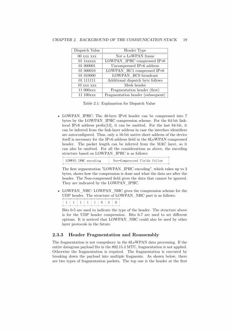
There are three types of headers indicated by the dispatch value: the meshaddressing header, the broadcast header and the fragmentation header. Thedispatch values as well as the corresponding header types are listed in Table2.1(x in the table means the value of the bit could be either 0 or 1):
2.3.2 Header Compression6LoWPAN does stateless header compression for the IPv6 header[14]. Since thecompression is stateless, any node on which the 6LoWPAN layer is implementedcan decompress the header.
Until now, the header compression is mainly applied on the IPv6 headerand the UDP header. The term LOWPAN_IPHC is used to indicate the IPv6encoding and LOWPAN_NHC is used to indicate the UDP encoding.
CHAPTER 2. BACKGROUND OF THE COMMUNICATION STACK 19
Dispatch Value Header Type00 xxx xxx Not a LoWPAN frame01 1xxxxx LOWPAN_IPHC compressed IPv601 000001 Uncompressed IPv6 address01 000010 LOWPAN_HC1 compressed IPv601 010000 LOWPAN_BC0 broadcast01 111111 Additional dispatch byte follows10 xxx xxx Mesh header11 000xxx Fragmentation header (first)11 100xxx Fragmentation header (subsequent)
Table 2.1: Explanation for Dispatch Value
• LOWPAN_IPHC: The 40-byte IPv6 header can be compressed into 7bytes by the LOWPAN_IPHC compression scheme. For the 64-bit link-local IPv6 address prefix[13], it can be omitted. For the last 64-bit, itcan be inferred from the link-layer address in case the interface identifiersare autoconfigured. Thus, only a 16-bit native short address of the deviceitself is necessary for the IPv6 address field in the 6LoWPAN compressedheader. The packet length can be inferred from the MAC layer, so itcan also be omitted. For all the considerations as above, the encodingstructure based on LOWPAN_IPHC is as follows:
The first segmentation "LOWPAN_IPHC encoding", which takes up to 2bytes, shows how the compression is done and what the data are after theheader. The Non-compressed field gives the data that cannot be ignored.They are indicated by the LOWPAN_IPHC.
• LOWPAN_NHC: LOWPAN_NHC gives the compression scheme for theUDP header. The structure of LOWPAN_NHC part is as follows:
Bits 0-5 are used to indicate the type of the header. The structure aboveis for the UDP header compression. Bits 6-7 are used to set differentoptions. It is noticed that LOWPAN_NHC could also be used by otherlayer protocols in the future.
2.3.3 Header Fragmentation and ReassemblyThe fragmentation is not compulsory in the 6LoWPAN data processing. If theentire datagram payload fits in the 802.15.4 MTU, fragmentation is not applied.Otherwise the fragmentation is required. The fragmentation is executed bybreaking down the payload into multiple fragments. As shown below, thereare two types of fragmentation packets. The top one is the header at the first

CHAPTER 2. BACKGROUND OF THE COMMUNICATION STACK 20
fragment:
The remaining fragments have a header with one extra 1-byte offset value:
As given in Table 2.1, the first 5-bit of the dispatch value indicates thatthe two figures above are the structures of the fragmentation headers. Thecomponent "datagram_size" indicates the total size of the IPv6 datagram beforethe fragmentation. The component "datagram_tag" gives the flag to a certaindatagram in the sending queue. It is common that different IPv6 datagramsare waiting in the sending queue. This flag helps to identify the same datagrambefore the fragmentation. Datagram_offset indicates the position of a fragmentin the original IPv6 datagram. With all these values, the receiver is able toreassemble the fragmented IPv6 datagram.
2.4 User Datagram Protocol (UDP)UDP[22] is a network protocol used for the Internet. The programs on theapplication level can employ UDP to transmit the datagram in the InternetProtocol network without prior setting up either the communication channel ordata paths.
Since there are not any implicit handshaking dialogues which provide thereliability and safety, the UDP communication is an unreliable service whichmay result in the datagrams either arriving out-of-order or missing withoutnotifications. However, UDP avoids the network overhead caused by the errorchecking and acknowledgments. Thus, the UDP communication is useful fora server answering small queries from a large number of clients. Meanwhile,the property that the UDP communication does not require acknowledgmentsmakes it suitable for use in real-time systems.
There are several network applications using the UDP protocol such as theDomain Name System (DNS) and streaming media applications (e.g., IPTV andVoIP). In this work, the mDNS protocol is also based on UDP communication.
2.5 Multicast Issues for IEEE 802.15.4In computer networks, multicast communication is the way to send datagrams toa group of specified receivers with a single transmission. Normally, the computer

CHAPTER 2. BACKGROUND OF THE COMMUNICATION STACK 21
listens to a multicast IP address and the corresponding port. Once the datagramis received from the network, the hardware is able to filter the non-interestedMAC addresses and keep the required one. However, the IEEE 802.15.4 de-vice, such as the target platform CC2530, does not support multicast directly.Thus, in this work, we suggest to use other transmission methods to replace thetraditional multicast.
There are two solutions to implement multicast in the IEEE 802.15.4 envi-ronment. Since broadcast communication is supported by the IEEE 802.15.4,it is feasible to replace multicast with broadcast. When the datagram size issmall enough to fit within a single unfragmented 6LoWPAN packet, it is possi-ble to use broadcast communication without the problems of missing fragments.However, since there is no MAC-level acknowledgment sent back for broadcasttransmissions, the transmission is less reliable compared to unicast transmis-sions. This may cause serious problems when the fragmentation of 6LoWPANis applied to the datagram. Once the data is fragmented, a single lost fragmentwill result in the invalidation of the entire datagram. In this case, a relativerational approach is to employ multiple unicast transmissions. Multiple unicastalso brings disadvantages. Since the node has to keep track of the neighbourtable in order to realize the multicast effect and perform multiple transmissions,the energy consumption and overhead are increased.

Chapter 3
Domain Name System
The Domain Name System (DNS) is a hierarchical naming system built ondistributed databases for computers, services, or any resource connected to theInternet or a private network[3]. It is an application-layer protocol.
3.1 Domain Name SystemCompared with the memorable domain name, it is difficult for human beings toremember the IP address of a computer. However, this IP address is essential foridentifying the location and MAC address of the network interface of that com-puter. Thus, DNS is invented to translate the so-called Fully Qualified DomainName (FQDN) into the IP address and vice versa. Because of the existence ofthe DNS, the Internet resource could be located world-wide. Meanwhile, DNSsupports the discovery of services in the Internet. Notice that the domain nameis persistent for a host while the IP address could be changed.
In this section, we start from the DNS hierarchical name space and thedistributed organization of the responsibility for the DNS system, to give thedetailed introduction about DNS.
3.1.1 Domain Name SpaceA domain name is the identification name label that defines a realm of admin-istrative autonomy, authority, or control in the Internet[3]. Simply, a domainname represents and identifies a certain Internet or private network resourcesuch as the web site. Domain names are formed by the DNS.
The domain name space consists of a tree of domain names. As shown inFigure 3.1, each node or leaf represents a domain in the domain name space.For each domain, there is one or more Resource Records (RRs) associated withit. The RR holds the information for the corresponding domain, such as hostaddress (A or AAAA) records, name server (NS) records and mail exchanger(MX) records. A domain zone may consist of one domain, or may consist
22

CHAPTER 3. DOMAIN NAME SYSTEM 23
of many domains. It is a portion of the global DNS name space for whichadministrative responsibility has been delegated and managed by a name server.
The details of the Domain Name and Resource Records are specified in RFC1034.
Figure 3.1: Domain Name Space for DNS
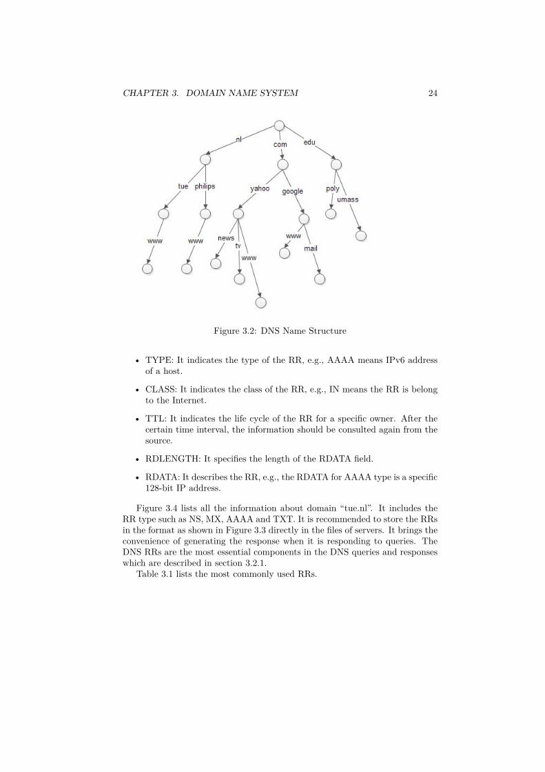
3.1.2 DNS Name SyntaxBased on the structure of the domain name space, the DNS name is hierarchi-cally structured, as shown in Figure 3.2. For any path from the root to thebottom, there is a domain name that represents it. For different parts of thedomain name space, there is a leveled DNS server in the Internet to handle thespecific information. An example is the host name “www.philips.nl”, where theright-most label is the top level domain. “www.philips.nl” belongs to the toplevel domain “nl”. The label “philips” specifies a sub domain of the “nl” domain.Accordingly, “www” is a sub domain of the “philips.nl” domain. From right toleft, the hierarchy of domains ranks from high to low.
3.1.3 Resource Records (RRs)As mentioned in the section 3.1.1, RRs hold the information for the correspond-ing domain and all the information stored in the zone files of the Domain NameSystem. All RRs have the same top-level format as shown in Figure 3.3[2].
• NAME: It is an owner name, e.g., the name of the node to which this RRpertains, it could be “example.local.”.
CHAPTER 3. DOMAIN NAME SYSTEM 24
Figure 3.2: DNS Name Structure
• TYPE: It indicates the type of the RR, e.g., AAAA means IPv6 addressof a host.
• CLASS: It indicates the class of the RR, e.g., IN means the RR is belongto the Internet.
• TTL: It indicates the life cycle of the RR for a specific owner. After thecertain time interval, the information should be consulted again from thesource.
• RDLENGTH: It specifies the length of the RDATA field.
• RDATA: It describes the RR, e.g., the RDATA for AAAA type is a specific128-bit IP address.
Figure 3.4 lists all the information about domain “tue.nl”. It includes theRR type such as NS, MX, AAAA and TXT. It is recommended to store the RRsin the format as shown in Figure 3.3 directly in the files of servers. It brings theconvenience of generating the response when it is responding to queries. TheDNS RRs are the most essential components in the DNS queries and responseswhich are described in section 3.2.1.
Table 3.1 lists the most commonly used RRs.

CHAPTER 3. DOMAIN NAME SYSTEM 25
Figure 3.3: RR Format
TYPE Description FunctionA IPv4 address record record a 32-bit IPv4 address
AAAA IPv6 address record record a 128-bit IPv6 addressMX mail exchange record maps a domain name to a list of
message transfer agents for that domainNS name server record specifies a host which should be
authoritative for the specified class and domainPTR pointer record pointer to a canonical nameSRV service locator record used for locate specific service in specific domainTXT text record for arbitrary human-readable and also
machine-readable text in a DNS record
Table 3.1: Common RRs
3.1.4 DNS Name ServerThe DNS is implemented by the DNS name server. The DNS name server isa server that stores the DNS records, and responds with answers to queriesagainst its database. There are 4 types of DNS name servers and these “types”are based on their roles during the DNS name resolution process:
• Root name server: It is contacted by the local name server. When a localDNS server receives a query, it contacts the root name server to get theIP mapping of top-level domains.
• Top-level domain (TLD) server: It is responsible for com, org, net, edu,etc and all top-level country domains such as uk, nl and cn. TLD servers

CHAPTER 3. DOMAIN NAME SYSTEM 26
Figure 3.4: RRs Example of a Domain
resolve the IP addresses of organizations and return it to the querier.
• Authoritative DNS server: It is responsible for the second-level domain.Here, authoritative DNS server is equal to the organization’s DNS serverand provides authoritative host names to IP mappings for organization’sservers. It is maintained by organizations.
• Local name server: It is also named “default name server”. Each InternetService Provider (ISP) such as companies or universities has one. Thequery sent from the host first arrives at the local name server, which willforward it to the high-level name servers.
Notice, these 4 types of DNS servers are distinguished according to the process ofthe DNS name resolution. The root name server is authoritative with respect toaddresses of TLD servers, and the TLD servers are authoritative with respect toaddresses of authoritative servers at organizations. In essence, the authoritativeDNS server means the name server that responds with answers that have beenconfigured by an original source. The original source is specifically configuredby the administrator.

CHAPTER 3. DOMAIN NAME SYSTEM 27
3.1.5 DNS ResolverThe DNS component installed in the client side is called a DNS resolver. Itis responsible for generating and sequencing the queries that finally achieve aresolution of the resource sought, e.g., translating a domain name into an IPaddress.
It is common for the DNS server to give the answer of the query after query-ing other name servers recursively. The simple DNS resolver relies on the re-cursive DNS server to perform the entire process of finding the information. Itis shown in section 3.2.2.
3.2 DNS OperationAs DNS is a distributed database system which is located world-wide, the com-munication between different DNS components is essential for the DNS opera-tion. In this section, we focus on this aspect and introduce how the DNS systemresolve the domain address to the IP address.
3.2.1 DNS Query and ResponseAll communications inside of the domain protocol are carried in a single formatcalled a message. A normal DNS message consists of several sections. Thereare 5 sections: Header, Question, Answer, Authority and Additional Sections,as shown in Figure 3.5 and described below.
Figure 3.5: DNS Packet Layout
Header Section The header section is always present in a DNS message. Theheader includes fields that specify which of the remaining sections are present,and also specify whether the message is a query or a response, a standard queryor some other opcode, etc[2]. The structure is shown in Figure 3.6.
Each item in the section indicates different information for the DNS packet,which is specified in RFC 1035[2].

CHAPTER 3. DOMAIN NAME SYSTEM 28
Figure 3.6: Header Section
Question Section The question section is used to carry the "question" in mostqueries, i.e., the parameter that defines what is being asked. The structure isshown in Figure 3.7.
Figure 3.7: Question Section
QNAME, QTYPE and QCLASS together formulate the required informationof what is being asked. For example, if QNAME = “www.tue.nl”, QTYPE =“AAAA”, QCLASS = “IN”, it means the IPv6 address of the domain name“www.tue.nl” is asked in the Internet.
Answer, Authority and Additional Sections Answer, authority, and ad-ditional sections share the same format, as shown in Figure 3.3, and all of themare called resource record sections. The answer section contains RRs that an-swer the question; the authority section contains RRs that point toward anauthoritative name server; the additional records section contains RRs whichrelate to the query, but are not direct answers for the question.
DNS Queries: The normal DNS query consists of the header and the questionsections. The DNS query is sent to the DNS server by the resolver or by other

CHAPTER 3. DOMAIN NAME SYSTEM 29
servers when the recursive look up is used.
DNS Responses: All the five sections of Figure 3.5 can be present in the DNSresponse which is generated by the DNS server. Figure 3.8 is a simple responsewhen the domain name “www.tue.nl” is being asked. In the question section,QNAME = “www.tue.nl”, QTYPE = “A”, QCLASS = “IN”. In the answer sec-tion, the canonical name of “www.tue.nl” is given which is “webserver.tue.nl”and the address of “webserver.tue.nl” is 131.155.2.83. In the authority recordand additional record sections, the name servers of “tue.nl” and the correspond-ing addresses are given.
Figure 3.8: Example of DNS Response

CHAPTER 3. DOMAIN NAME SYSTEM 30
3.2.2 DNS Name ResolutionA simple example of the DNS name resolution process is given in Figure 3.9[36].In this example, a host “sic.poly.edu” requires the IP address of the host“gain.cs.umass.edu”. A DNS query is sent to the local DNS server first. If thelocal server has the available information in its cache, it will directly respond tothe host. Under this condition, the request to the root or top-level DNS serveris not required. If the local server does not have the answer, it should forwardthe query to the root DNS server. After the local server receives the response(the address of the TLD DNS server for that query) from the root server, it willquery the address of the authoritative DNS server from the TLD DNS server.Afterwards the local server should query the authoritative DNS server and getthe response. Finally, the response will be forwarded to the requesting host“sic.poly.edu”. The numbered arrows in Figure 3.9 indicate the order of thedifferent requests and responses.
Figure 3.9: Name Resolution Example
3.3 DNS ServicesAs described in section 3.1, DNS translates the so-called Fully Qualified Nameinto the IP address and vice versa. In traditional managed networks, the DNSsystem provides each host the information such as its host name, IP address anddomain name server address (DNS server). All the information is configured bythe DHCP protocol[29].
CHAPTER 3. DOMAIN NAME SYSTEM 31
Using the DNS system, nodes can look up addresses of nodes supplyingservices, such as the email service (SMTP)[30], the HTTP[31] service or anyother services. For example, a user is requesting the “http://www.tue.nl” URLin the web browser. In order to send this request to the web server named“www.tue.nl”, the browser has to know the IP address of that server. Thebrowser should extract the requested domain name and pass it to the DNSclient installed in the host. Afterwards, the DNS client will process this requestin the DNS system and return the IP address of the requested HTTP server tothe web browser. Finally, the web browser will set up a TCP connection withthat HTTP server by using the received IP address.
In the above example, “www” is a part of the host name, so the DNS is notused to discover whether the “HTTP” service exists in the “tue.nl” domain ornot. For discovery, DNS provides the protocol named DNS-SRV[5] to find andlocate the specific service. The DNS-SRV RR specifies the location of the serverfor a certain protocol and domain. With the DNS-SRV RRs, clients are ableto ask for a specific service or protocol in a specific domain, and get the namesof available servers back. For example, if a client wants to find out the HTTPserver in the “example.com” domain, it may query with the QTYPE “SRV” andQNAME: _http._tcp.example.com
Here, “http” is the desired service, “tcp” is the desired protocol and “exam-ple.com” is the domain to which this RR refers.
In the SRV type of the resource record of the response, there would bespecific target names to indicate which servers provide the desired service inthe specified domain. By the target name, the client is able to look up the IPaddress of that server and start the communication.
With the DNS-SRV protocol, it would be possible to discover different typesof services. However, for many of the existing protocols, alternative discoverysolutions exist, such as search engines for HTTP, SSDP for UPnP, or UDDI forweb services.
Although DNS-SRV is available for the service discovery, there are someshort-comings:
• When multiple service records are reported, the semantics of the resultsis that they can be used as alternatives for the same functionality.
• Due to the service identifier, e.g., like http, it is only possible to discoverservices with known protocols.
To remove the short-comings, the DNS-SD protocol is developed. AlthoughDNS-SD is developed together with the Multicast DNS, it does not dependon Multicast DNS. DNS-SD could also be used in the normal DNS system.However, this topic is out of the scope in this work.
It is not always the case that a DNS system is installed in the network.Therefore, the concept of Multicast DNS is introduced in the IETF document[1]and described in Chapter 4.

Chapter 4
Multicast DNS
Multicast DNS is a technology using the traditional DNS programming inter-face, packet formats and operating semantics, to replace the function of theconventional DNS server, especially in small area networks. It is a promisingtechnology chosen to implement service discovery for wireless ad-hoc networks.
4.1 Multicast DNS MotivationsMulticast DNS is a joint effort by participants of the IETF Zero ConfigurationNetworking (zeroconf)[6] and DNS Extensions (dnsext)[7] working groups. Therequirements are driven by the Zeroconf working group; the implementationdetails are a chartered work item for the DNSEXT group[8]. Multicast DNS isused by Bonjour[23] of Apple Inc and Linux Avahi[24] service discovery systems.
There are in general four considerations for the practical significance of Mul-ticast DNS:
• to work in ad-hoc or unmanaged networks (by using a dedicated, specialpart of the DNS namespace): It is not always the case that the traditionalDNS system is installed in every type of network. In ad-hoc or unman-aged networks, no DNS system is installed, hence the node does not knowwhere to find the information such as other node’s domain name, IP ad-dress, or domain name server address (DNS server). In order to solvethis problem, the concept of ad-hoc service discovery is introduced. Itis an important addition to ad-hoc networks since it enables sharing offunctionality and resources and makes it possible to run distributed ap-plications without the need for manual installation and maintenance of aservice database. Multicast DNS provides the ability to perform DNS-likeoperations on the local link in the absence of any conventional unicastDNS server[1]. Multicast DNS and its companion technology DNS-basedService Discovery [DNS-SD][4] were created to provide the IP networkingwith the ease-of-use and autoconfiguration of the system.
32

CHAPTER 4. MULTICAST DNS 33
• to extend DNS: The traditional DNS queries are remaining valid in themDNS system and the mDNS Responder (the naming convention of themDNS standard for the server part) may use the cached knowledge toresolve both the traditional DNS and mDNS queries. Meanwhile, themDNS Responder might also contact the normal DNS server to resolvethe query. All these conditions hold because of Multicast DNS using thesame programming interface, packet formats and operating semantics asnormal DNS does. The programming interface for the mDNS design inChapter 5 is quite similar with the DNS resolver library of Linux.
• to work if DNS does not work: Since the same programming interface,packet formats and operating semantics are used, Multicast DNS is ableto multicast the normal DNS queries to do the same job as DNS does ina certain context. When the DNS does not work, Multicast DNS can beviewed as the backup solution.
• have an effective, ad-hoc service discovery mechanism: Based on MulticastDNS, DNS-SD and also SRV[5] are used to solve the problem of servicediscovery.
Based on all these considerations, we introduce the mDNS technology as themain technology in this work. During the introduction, some key characteristicsof Multicast DNS will be described in this chapter. Notice, Multicast DNSsupports both IPv4 and IPv6. IPv6, as the promising Internet Protocol and thedevelopment trend, is the only version of IP to be considered in this work.
4.2 Multicast DNS Name SpaceNormally, Multicast DNS is applied only on the link-local scope, which meansevery node in the local area that can be reached without routing. Specifically,the mDNS data packet will not be forwarded by any router. In this work,the discussion about the Multicast DNS is mainly constrained to the link-localscope.
In the link-local scope, IETF defines one top-level domain “.local.” which isreserved for the link-local name used in Multicast DNS. Compared with the hi-erarchical structure used in traditional DNS name convention, an mDNS nameis recommended in a flat structure which is defined by IETF[1]. It allows any de-vice to generate its link-local domain name in the form: “single-dns-label.local.”,e.g , “MyComputer.local.”. The top-level domain “.local.” is meaningful only onthe link where it originates. The mDNS name structure is shown in Figure 4.1.
Meanwhile, it is also possible for users to define the hierarchical name bythemselves. As shown in Figure 4.2, the link-local name could be “c.printing.local.”or “d.printing.local.”, which is easy to read and distinguishable for the users. Forthe view of Multicast DNS, “c.printing” or “d.printing” is still in one domain.

CHAPTER 4. MULTICAST DNS 34
Figure 4.1: Multicast DNS Name Structure
Figure 4.2: Hierarchical Name Structure for Multicast DNS
The domain “.local.” is treated the same as any other domain that mightappear in the DNS search list but has only local significance. If the domainname ends with “.local.”, it means this message should be processed by themDNS protocol.

CHAPTER 4. MULTICAST DNS 35
4.3 Multicast DNS Name ResolutionThe name resolution process for traditional DNS is given in Chapter 3. Com-pared with the traditional DNS name resolution, Multicast DNS achieves thisgoal in a more direct way. When Multicast DNS is implemented, every node isable to act as both the server and the client. This is the most essential charac-teristic for mDNS protocol. In principle, when the total number of nodes in thenetwork is small, Multicast DNS could be extremely efficient.
Assume there are three basic devices, node1, node2 and node3, as shown inFigure 4.3. Every device has its own functionality which is mentioned in thefigure.
Figure 4.3: Wireless Ad-hoc Network Example
Assume node1 requires to get the IP address of node2. Since there is noconventional DNS server in this small network, node1 does not know where toask for the information. In this case, node1 sends the multicast query askingfor the IP address of domain name “node2.local” to all devices in this localnetwork. Consequently, both node2 and node3 in the local network receive thequery and decide to respond to it or not. Since node2 has the authority for thisquery, it generates the response to answer the question. Obviously, node2 actsas the server for this query. The generated response will be multicast to thelocal network. Later, node1 will deal with the received message accordingly. Forexample, it could access node2 and make use of the printing service. There aretwo approaches for node1 to know that node2 provides the printing service. Thefirst approach is that node1 may cache the periodical service announcement sentby node2. The second approach is that node1 may use the DNS-SD to discover

CHAPTER 4. MULTICAST DNS 36
the service provided by node2. Meanwhile, node3 may also renew the receivedinformation in its cache. In this example, node2 has the authority for the querybecause it has the domain name “node2”. On this link-local scope, only thedevice “node2” can use this domain name once it bootstraps and multicasts theannouncement with the domain name “node2”.
4.4 Resource Records (RRs)Compared with the traditional RRs, mDNS RRs have the same format andcontent. They are described in Chapter 3.
There are two kinds of RR sets for the mDNS protocol: shared and unique[1].
• shared: it is the resource record set where several mDNS Responders haverecords with the same name, rrtype and rrclass, and all these Respondershave the authority to respond to a particular query.
• unique: it is the resource record set that only holds by a certain Responderwith the specific name, rrtype and rrclass, and only this Responder hasthe authority to respond to the specific query with that name, rrtype andrrclass.
Since every node in the local network is able to respond to the certain query andthe network traffic is preferred to be reduced, the unique resource record set ismore frequently used by mDNS implementations. Before an mDNS Responderclaims the ownership of a resource record set, it has to probe to verify that thereis no other Responder already claims ownership of that RR set. Multicast DNSachieves this functionality by performing Probing and Announcing when it isstarting up. Whenever an mDNS Responder starts up, wakes up from sleep,or receives an indication of a network interface “Link Change” event, it has toperform the two startup steps: Probing and Announcing.
Probing The mDNS Responder needs to make sure that all resource recordsthat are desired to be unique in the local network have been verified. Theprimary example is the host’s address record which maps its unique host nameto its unique link-local IP address. If the host name is already in use, the hostmust change the name and probe again.
In the Probing step, the node multicasts the queries for three consecutivetimes using the desired resource record name and class. If there is any conflictmessage received from other Responders in the local network, the Responderhas to change the name and repeat the startup step from the beginning. Figure4.4 indicates the procedure for the startup of node 1. Node 2 and node 3 are inthe normal state which means they have finished the startup steps.
Once the node confirms it is unique in the local area, it goes to the Announcestep.

CHAPTER 4. MULTICAST DNS 37
Figure 4.4: Message Sequence Chart for Startup
Announcing In the Announcing step, the Responder must send an unso-licited mDNS response containing all the newly registered resource records inthe answer section to the link-local scope. This unsolicited mDNS response isused to claim the ownship of the specific resource records. The unsolicited re-sponse must be sent at least twice, and the delay between additional unsolicitedresponses should be increased by a factor of two for each response.
4.5 mDNS QueryThe semantics of the mDNS query is quite similar to the normal DNS query.There are two kinds of mDNS queries: one-shot mDNS queries and continuousongoing mDNS queries[1].
• One-shot mDNS queries: In principle, one-shot mDNS queries could besent from a simple DNS resolver (the client part of DNS). The mDNS re-solver (the client part of Multicast DNS) may just send the query blindlyto FF02::FB (the specific multicast IPv6 address for mDNS). This func-tionality requires only minor modifications to the traditional DNS resolverlibrary. This kind of simple DNS resolver only takes the first response itreceives. The queries sent by this DNS resolver must not use the UDPsource port 5353, which is reserved for the fully-compliant mDNS resolver.

CHAPTER 4. MULTICAST DNS 38
• Continuous mDNS queries: When more than one response is needed bya certain query, or the querying operation continues until no further re-sponses are required, the fully-compliant mDNS resolver, rather than thesimple DNS resolver, is needed. If the IPv6 address of another host is re-quired, one-shot mDNS queries are enough. Nevertheless, if the operationis browsing to present DNS-SD services on the local network, the mDNSresolver will continuously send the query to ask the available services ex-isting in the network. Then, the multicast responses are required untilthe user application asks to stop. On this condition, the compliant mDNSresolver is necessary. The compliant mDNS resolver must send the queryfrom the UDP source port 5353, and listen for mDNS responses sent toUDP destination port 5353. “5353” is the well-known UDP port assignedto Multicast DNS.
In order to reduce the traffic in the local network, Multicast DNS allows multiplequestions in one query. It is identical to several queries which involve a singlequestion each. The mDNS query is able to require unicast mDNS responses andit is even possible to unicast the mDNS query to a specific destination.
4.6 mDNS ResponseFor any mDNS response, the resource record section of that response must beexplicitly authoritative by the mDNS Responder. Once an mDNS Responderclaims the ownership of a resource record set in the Announcing step, it is au-thoritative for that resource record. Compared with the normal DNS response,a small difference is that the Question Section of the mDNS response must beempty.
There are the explicit rules for matching the question[1]:
• The record name must match the question name.
• The record rrtype must match the question qtype unless the type is“ANY”.
• The record rrclass must match the question qclass unless the qclass is“ANY”.
Responding to address queries is one of the most significant roles played byMulticast DNS. The name resolution procedure is already introduced in section3.3. The mDNS Responder is able to respond to Multi-Question Queries, andmeanwhile reduce the number of response packets.
• Responding to Multi-Question Queries: If it receives the query which con-tains more than one question, the Responder should generate the responseif it has the authority to answer any of the questions. The Respondershould randomly delay for a certain time before sending the response, forthe consideration of reducing the network congestion.
CHAPTER 4. MULTICAST DNS 39
• Response Aggregation: When it is possible, the Responder should waitfor a certain time in order to aggregate more responses into one responsepacket. For example, when a Responder is going to send a response withthe address record, it receives the query about the service provided byitself, then the Responder is able to aggregate these two records into oneresponse packet. It is also a way of reducing the traffic load. This func-tionality is done by the Responder.
4.7 Multicast DNS PropertiesNext to the development of conventional DNS, Multicast DNS has its own char-acteristics. All these characteristics make it possible to implement MulticastDNS in reality.
4.7.1 Traffic ReductionMulticast DNS could generate a large amount of traffic because of the charac-teristics of multicast. In order to avoid the potential burden to the networkcaused by Multicast DNS, some particular techniques are applied[1].
• Known-Answer Suppression: When the client sends out the query to whichit already knows some answers, it should populate the Answer Section ofthe mDNS query with these answers. The mDNS Responder must notanswer the question if the answer is already included in the Answer Sectionof the query. This technique is only used for the query which asks for theshared resource record of the Resolver. For example, there could be severalnodes in the local area providing the printing service. If a user applicationalready knows one printing machine, but it does not want to use it, theknown-answer suppression scheme could be applied. The mDNS Resolverwill not ask the unique resource record which belongs to itself.
• Multi-Packet Known-Answer Suppression: When there are too many an-swers in the Known-Answer Section, the TC (Truncated) bit must be set.Then multiple query packets rather than one would be sent. All thesequery packets contain a part of the known answers.
• Duplicate Question Suppression: If a host receives a query of which theresource record is the same as it is about to ask, it will cancel the plan ofsending that query.
• Duplicate Answer Suppression: If a host receives a response of which theresource record is the same as it is about to send, it will cancel the planof sending that response.

CHAPTER 4. MULTICAST DNS 40
4.7.2 Source Address CheckFor all mDNS responses, the IP TTL of them should be set to 255. Based on thevalue of the IP TTL, the mDNS Resolver checks whether the received message isoriginated on the local link or not. If the IP TTL of the received DNS responseis not 255, the Querier will silently discard it.
When an mDNS query is carried out, the host sending the mDNS querymust only process the response that originates from the local link. There aretwo ways to test whether a response originates on the local link or not:
• For all the responses, the multicast address in IP headers must be FF02::FB.
• For the response with the source IP address prefix FE80::/10, it must besent from the local link.
4.7.3 Multiple InterfacesOne host can have different network interfaces. All interfaces from the same hostmay choose the same host name and that host name should be defended by allthe active interfaces. If the host name is not unique for one of the interfaces,the host should configure a new host name for all the interfaces.
4.7.4 Multicast DNS Character SetHistorically, the conventional DNS is encoded as US-ASCII text, so it is lack ofany support for non-US characters and limited to letters, digits and hyphens.However, actually the DNS specification does not constraint the limitation toDNS names.
In contrast, all names in the mDNS implementation must be encoded as theprecomposed UTF-8 “Net-Unicode” text. Since US-ASCII can be considered asa subset of UTF-8, Multicast DNS is compatible with the existing DNS API,library and clients. It is not recommended to use non-US characters to MulticastDNS at this stage. However, it leaves the space for the further development tobreak through restrictions of the conventional DNS character set.
4.8 Multicast DNS and DNS ComparisonsThe traditional DNS programming interface, packet formats and operating se-mantics is the foundation of Multicast DNS. Multicast DNS inherits the prop-erty of DNS and makes some changes to suit the specific usage environment.Thus, there are some commonalities and differences between Multicast DNSand DNS. Table 4.1 lists the comparisons of these two techniques from differ-ent points of view. Notice, the mDNS packet could be larger that 512 bytes.However, in order to make it compatible with the conventional DNS packet, itis not recommended to exceed the limitation of 512 bytes.

CHAPTER 4. MULTICAST DNS 41
Multicast DNS Traditional DNSDomain name Flat structure, Hierarchical structure,
maximum size: 255 bytes maximum size: 255bytes for each domain
IP address Link-local/Global Global IP addressIP address
Name server record No YesStart of authority record No YesSource/Dest UDP port 5353 53
UDP packet size Larger than 512 bytes 512 bytesQuestion number in query One or more OneKnown answer suppression Yes No
Query ID field Ignore UseQuestion Section in response Does not exist Exist
Server Each node Specialized DNS serverSend method Multicast/Unicast Unicast
Table 4.1: Comparison between Multicast DNS and DNS
4.8.1 Advantage of Multicast DNSMulticast DNS realizes the name resolution between IP addresses and hostnames. The DNS-like operation is executed on the local link in the absenceof any conventional DNS server. There is no requirement for administration orconfiguration of the mDNS system. In addition, no infrastructure is needed forthe system to implement the mDNS service. Even when the infrastructure ofthe system fails, it still works[1]. It is also worth mentioning that the local DNSdomain names are free for use which saves the annual cost for the global domainname.
Furthermore, Multicast DNS allows the detection of the name collisions dur-ing the probing process without extra error detections, which also saves the net-work resources. Last but not least, according to the basic principle of MulticastDNS, if the IP prefix of the response is FE80::/10, it can explicitly detect thatthe response is received from the local network.
4.8.2 Disadvantage of Multicast DNSMulticast DNS is not suitable to be used in the network with a large number ofnodes. Since most queries and responses are sent by multicast, it may generatea large volume of traffic. When there are too many nodes in the network,the burden of the mDNS transmissions on the link will severely influence theperformance of the network. Assume there are 1000 nodes in the local network.For the startup of each node, there will be 1000 multicast probing queries andunsolicited responses periodically. At the same time, there will be also themulticast queries and responses generated by different nodes. Apparently, that

CHAPTER 4. MULTICAST DNS 42
will cause an immense burden on the network. It is straightforward that theconventional unicast DNS is more suitable to be applied in such situation.
Multicast DNS cannot be used in multiple IP subnets and it is recommendedto be applied only on the link-local scope. This is a huge limitation. In contrast,the conventional DNS is the accepted standard which is used world-wide.

Chapter 5
Specification of mDNSImplementation
This work focuses on the Multicast DNS applied to low-resource devices. Thereare several differences between the mDNS application on low-resource devicescompared to those on normal devices.
When Multicast DNS is applied on normal devices, it works as the normalDNS system. All RRs, such as MX, NS and SOA, have to be considered andhandled. On low-resource devices, several functionalities can be left out. Mean-while, it is also impossible to implement all functionalities of Multicast DNS onlow-resource devices because of the constraints on the data/program memories.
In this chapter, a specific design is proposed for the Multicast DNS imple-mentation, which is suitable to be applied on low-resource devices. In section5.1, the existing DNS and mDNS implementations are introduced. We brieflydiscuss why it is necessary to give this specific mDNS implementation design onthe low-resource devices. Section 5.2 and 5.3 describe the design considerationsas well as the design goals. Section 5.4 defines the implementation details. ThemDNS APIs are given in section 5.5. Section 5.6 introduces the structure of thedesigned mDNS Library while section 5.7 gives the details about how the pro-posed mDNS library is implemented. The data structure for the mDNS designis given in section 5.8. At the end of this chapter, this work provides a potentialsolution for implementing the mDNS service on the Contiki OS.
5.1 Recap for Existing DNS/mDNS Implemen-tations
In order to realize the mDNS service, one of the direct solutions is modifying theexisting DNS implementation. The Linux system library "libresolv.so" handlesthe resolver part of the DNS. Since it takes 75 KB of the Flash and 11 KBof the RAM for the simple resolver functionality, it is difficult to transplant
43

CHAPTER 5. SPECIFICATION OF MDNS IMPLEMENTATION 44
the “libresolv.so” on the low-resource devices. Take the chip CC2530[17] as anexample, its RAM is 8 KB so that it is far from meeting the requirement ofthe libresolv.so. The detailed introduction to CC2530 is given in Appendix B.Nowadays, BIND[9] is by far the most commonly used DNS server software inthe Internet. In combination with the libresolv.so, Bind is also too big for thetarget.
Flash (bytes) RAM (bytes)libresolv.so 76864 11732
Bind 41442 1380Bonjour 68817 6180Avahi 335382 3740
Table 5.1: Size of Existing DNS/mDNS Implementations on Linux
There are also several specific mDNS implementations. Among these imple-mentations, Bonjour[23] and Avahi[24] are the most ubiquitous but very largeand unsuitable for embedded devices. In general, the code for the existingmDNS implementations is rather large and unwieldy for low-resource devices.As shown in Table 5.1, Avahi takes 327 KB of the Flash which is larger thanwhat CC2530 can afford. On a Linux platform, it is necessary for Bonjour totake some of the libraries of Avahi when it is running. Apparently, it is morethan what CC2530 can afford.
Based on these considerations, it is reasonable to design and write the codefrom scratch for implementing the mDNS protocol on the low-resource devices.Thus, this work provides a specific mDNS implementation design.
5.2 Design ConsiderationsThis design of an mDNS implementation aims at making the Multicast DNSrunning on low-resource devices. There are several issues to be considered:
• The functionality consideration: It is neither necessary nor realistic toimplement all the DNS functionalities on small devices. The key pointis making the mDNS protocol working in the ad-hoc network consistingof low-resource devices. Meanwhile, the mDNS message should be recog-nizable by the conventional DNS server and the mDNS Library is able toprocess the normal incoming DNS messages.
• Low-resource device consideration: Compared with normal devices, low-resource devices have small memories and low computing capabilities. Itis especially important to store the data in an economical way and reducethe complexity of data processing.
• Network consideration: The capabilities of the wireless ad-hoc networkare not as powerful as other types of networks. The packet size should

CHAPTER 5. SPECIFICATION OF MDNS IMPLEMENTATION 45
not be large in order to improve the success rate of data transmission. Forexample, IEEE 802.15.4 standard restricts the packet size to 127 bytes inthe MAC layer[10], which means there could be potentially a large amountof packets passing through the network. As introduced in section 2.3.1,the normal mDNS packet takes more space than a single 802.15.4 packet.In this case, the fragmentation is necessary in the IEEE 802.15.4 wirelessnetwork environment. Accordingly, there are more generated packets inthe network. The transmission delay should be controlled to avoid thenetwork congestion.
• Energy consumption consideration: The battery life is an important issuefor low-resource devices. The radio and processor activities should becontrolled to improve the battery lifetime.
5.3 Design GoalsThis work gives specific design goals in order to give a reasonable blueprint andachieve the economical and ideal implementation quality.
• Design Multicast DNS suitable for low-resource devices. That is to say,this mDNS design targets at the device with small memory and low com-puting capability. The Contiki OS and CC2530 serve as an example withrespect to the footprint and capabilities. Meanwhile, the specific APIs ofthe Contiki OS could be called by the Multicast DNS when necessary (ofcourse, the specific APIs could also be called by other OSs in order toimplement Multicast DNS based on this design).
• Use the flat structure for the mDNS name.
• Design the database to store the authority RRs of the host itself and theRRs received from other nodes in the local area.
• Make the mDNS transaction to be independent of other applications run-ning in the system (Contiki OS).
• Design the APIs to intercommunicate with the system.
• Where there are tradeoffs between the cost of acquiring RRs informationand the update frequency, the source of the data should control the tradeoffin order to make the protocol applicable for the low-resource devices.
5.4 Subset of functionalitiesIn order to give a reasonable blueprint for the mDNS implementation design,there should be a definite statement specifying what functionalities are going tobe implemented. This subsection lists the detailed functionalities from differentperspectives:

CHAPTER 5. SPECIFICATION OF MDNS IMPLEMENTATION 46
• The mDNS implementation does not support the recursive look-up, be-cause it is unnecessary to carry out such operation in the multicast envi-ronment.
• Consider the IPv6 address only. Since the mDNS design is based on thelow-resource devices on the local area and most IEEE 802.15.4 devicesare able to automatically generate the link-local IPv6 address[10], it ismuch more convenient to neglect the IPv4 address. This design will notinfluence the communications among different devices on the local link.
• The Local Database should store the local information and the Cacheshould store the database of the remote nodes. These databases are allbased on storing RRs.
• The following RRs will be supported in the mDNS implementation: AAAA,PTR, TXT and SRV.
• In this design, the “CLASS” has only one option “IN”.
• In order to minimize the size of the mDNS packet, neither the known-answer suppression nor the multi-packet known-answer suppression areimplemented in the design.
5.5 mDNS APIsThe mDNS API is designed for the system applications when they want toaccess the mDNS service. In this design, when the mDNS API is called by theuser application, an internal message would be transmitted to the mDNS threadand activate it. This is shown in Figure 5.1. Once the API is called, the userapplication should be blocked. The API listed below serves the Resolver part ofthe mDNS Library and is defined in the C language. For the Server part, therecould be other mechanisms to activate it which are introduced in section 5.9.
int mDNS_internal_query(int q_type, string out, string fqdn, stringservice);
@param q_type The type of the user query.
• When q_type is set to ns_t_aaaa, the user query asks the IPv6address of the fqdn.
• When it is set to ns_t_ptr, the user query asks the PTR records forthe fqdn.
• When it is set to ns_t_txt, the user query asks the TXT records ofthe fqdn.

CHAPTER 5. SPECIFICATION OF MDNS IMPLEMENTATION 47
• When it is set to ns_t_service, the user query asks the specific serviceof the fqdn.
@param out The string for the result of the required information. Itcould be the IPv6 address, the PTR record, the TXT record and the resultfor the service query. If the result does not exist in the mDNS environment,out will be empty.
@param service It could be different service types, such as HTTP. Thisvalue is only valid when the q_type is set to ns_t_service. For other cases,it is ignored.
@return On success, return 0. On failure, return -1.
The API below is used to start the mDNS Library. Once it is called, themDNS Library begins to listen to the incoming messages from the network.
int Start_mDNS();
@return On success, return 0. On failure, return -1.
5.6 Elements of Multicast DNSA conventional DNS system mainly consists of three parts[3]: the domain namespace with resource records, the name server and the resolver.
Among these components, the domain name space with resource records isquite similar to that used in the Multicast DNS. When the Multicast DNS isapplied, the node acts as both the client and the server. Therefore, this workcombines the name server with the resolver into a single library, named mDNSLibrary. Thus, in this work, mDNS system consists of two parts: the domainname space with resource records and the mDNS Library.
Figure 5.1 shows the construction of the mDNS Library and the interactionof the Library within the environment. The mDNS Library can be conceptuallyseparated into two parts according to the functionalities: the Resolver partand the Server part. Meanwhile, there are two memory areas allocated withinthe mDNS Library, named Local Database and Cache, which are discussed insection 5.8. The interaction between the Resolver and the environment is shownin step a, b and c in Figure 5.1. The interaction between the Server and theenvironment is shown in step d in Figure 5.1. All these issues will be discussedin the next section.

CHAPTER 5. SPECIFICATION OF MDNS IMPLEMENTATION 48
Figure 5.1: mDNS Library
5.7 Implementation of the mDNS LibraryThe mDNS Library is an individual thread on the host OS. Considering whenthe mDNS thread is running, it should not disturb other applications running inthe OS. For example, when the mDNS library is waiting for the UDP response,it could not block other applications to use the UDP service. This work usesthe Contiki OS as the target OS platform, on which the concurrent activitiescan be realized in a specific way, as discussed in section 5.9.
As mentioned in the previous section, the mDNS Library could be concep-tually separated into two parts: The Resolver (client) part and the Server part.The Resolver and Server take one single process inside the mDNS Library whichis introduced in section 5.9.
Resolver Part: The Resolver of the mDNS Library is able to communicatewith the normal user program. When the mDNS API is called by user programs,the Resolver looks for the required information in its Cache. This procedure isshown in step a in Figure 5.1. If the required information is not available, theResolver will generate an mDNS query and send it to the local network. Oncethe answer is received, the mDNS Library will refresh its Cache and give theresponse back to the user program. This procedure is shown in step b in Figure5.1. The user program should be blocked until the required response is received.Once the required information is received, the user program is unblocked. Thisprocedure is shown in step c in Figure 5.1. There should be a timer set for theuser program. If there is no available information in stipulated time, the mDNSLibrary will return -1 and unblock the user program.

CHAPTER 5. SPECIFICATION OF MDNS IMPLEMENTATION 49
Server Part: The Server of the mDNS Library keeps on communicating withthe foreign mDNS Libraries according to the rules of the mDNS protocol. Theyare communicating based on the mDNS queries and responses. When the queryis received from the network, the Server will check whether to respond to thequery or not. If the Server is authoritative to that query, it will generate anmDNS response and send it. This procedure is shown in step d in Figure 5.1.
In this section, the behavior of the mDNS Library is divided into 4 sections.These behaviors cooperate together to realize the functionalities of the Resolverand the Server.
5.7.1 Transforming Users Request into a QueryAs shown in step a in Figure 5.1, when the user program inside the OS calls themDNS API, the user query is transmitted to the resolver. The Resolver shouldtransform the client’s request into a suitable format which can be processed byitself. To be specific, the request is transformed into the corresponding RR setwith the specific QNAME and QTYPE. The resolver is able to search the RRin the Cache. When the QNAME and the QTYPE correspond to a single nameand a type in the Cache, the Resolver will return an internal response to theuser program with the corresponding RR set. This procedure is shown in Figure5.2. The internal response is the return value of the mDNS API described insection 5.5, and the user program makes use of the value in the string “out”.
Figure 5.2: The Communication between User Program and Resolver
When the user query is sent, the user application should be blocked untilthe required information is retrieved from the Resolver, as shown in Figure5.2. Meanwhile, once the user query is received, the mDNS thread is activated.

CHAPTER 5. SPECIFICATION OF MDNS IMPLEMENTATION 50
A specific block/activate mechanism is employed by the Contiki OS, which isintroduced in section 5.9.
5.7.2 Sending the QueryAs discussed in the previous section, if the required information is not foundin the Cache, the Resolver would generate an mDNS query and send it to thenetwork. This procedure is shown in Figure 5.3.
Figure 5.3: Resolver Sends the mDNS Query
One of the basic tasks for the mDNS Library is to format the query which isspecified by the user application’s request and send the generated query to thelocal link. Every section of the response should be valid according to the mDNSspecification[1]. The normal way of doing this is assigning each item with thecorrect values in a buffer and then sending them as a whole.
There are only two choices for the mDNS Library:
• Multicast the query to the local link.
• Unicast the query to a certain node on the local link.
In this design, there is only one case to use unicast for the message transmission.When a conflict informing the RRs are already occupied by existing nodes isdetected, the conflict response should be unicast to the start-up node. This is forthe consideration of avoiding the unnecessary traffic. In other cases, multicastis recommended as the only choice.
In any case, this work assumes that the mDNS Library is multiplexing atten-tion between the request from the user application and the internally generatedrequest.
For mDNS continuous queries, this work recommends to use the same querysending method inside the mDNS Library and send an mDNS query periodically.Figure 5.4 indicates the procedure of the continuous query.

CHAPTER 5. SPECIFICATION OF MDNS IMPLEMENTATION 51
Figure 5.4: The Continuous Query
5.7.3 Processing the QueryWhen the mDNS Library receives the query from the network, it acts as theServer. Once the mDNS query is received, the Server will extract the usefulinformation and search for it in the Local Database to see whether to respondto the query or not. This procedure is shown in Figure 5.5.
There are specific matching rules for the mDNS Library to process the query:
• The record “name” must match the question name
• The record “rrtype” must match the question qtype.
• The record “rrclass” must match the question qclass.
When the query is in line with all these matching rules listed above, thematched record set would be inserted into the answer section to compose aresponse. At the same time, the server starts to generate other sections of theresponse for the query. In short, the response should be valid according to themDNS specification. Similar to the generation of an mDNS query, the mDNSLibrary should assign each item with the correct values in a buffer, and sendthem as a whole.
The algorithm for matching the query to the stored RRs depends on thedata structure used for storing the RRs. The detailed matching algorithm islisted below:
1. Extract the length of the QNAME and search for it in the Local Database.If there is no match for the length, ignore that query.
2. Extract the remaining part of the QNAME and search for it in the LocalDatabase. If there is no match for the name, ignore that query.

CHAPTER 5. SPECIFICATION OF MDNS IMPLEMENTATION 52
Figure 5.5: Processing the Query
3. If the QTYPE is also matched in a single path, copy the RR set in thatpath from the root into the answer section.
4. Set all the values in the Header Section and send the response.
The detailed data structure for Local Database and Cache is introduced in sec-tion 5.8, which describes more about how the data could be stored and searched.
Compared with normal DNS, the recursive service is excluded in the mDNSmatching algorithm.
5.7.4 Processing the ResponseThere are two kinds of mDNS responses:
• The mDNS response which answers the mDNS query. This kind of re-sponse is shown in Figure 5.3.
• The unsolicited response which announces its resources and services whenthe node starts up. This kind response is shown in Figure 5.6.
The mDNS implementation recommends to adopt the same approach to processboth kinds of the responses. The mDNS implementation may cache any mDNSresponse messages it receives, for the possible use in the future. Comparedwith the normal DNS, the mDNS protocol does not care about which queryasks the certain question. In contrast, Multicast DNS only cares about whetherthe information is useful or not. Thus, the mDNS Library should only checkwhether the same RR set exists in the Cache. If the RR set is already stored,
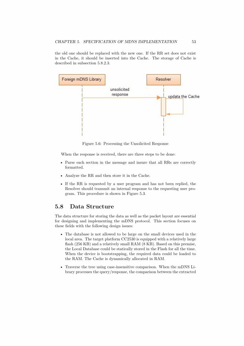
CHAPTER 5. SPECIFICATION OF MDNS IMPLEMENTATION 53
the old one should be replaced with the new one. If the RR set does not existin the Cache, it should be inserted into the Cache. The storage of Cache isdescribed in subsection 5.8.2.3.
Figure 5.6: Processing the Unsolicited Response
When the response is received, there are three steps to be done:
• Parse each section in the message and insure that all RRs are correctlyformatted.
• Analyze the RR and then store it in the Cache.
• If the RR is requested by a user program and has not been replied, theResolver should transmit an internal response to the requesting user pro-gram. This procedure is shown in Figure 5.3.
5.8 Data StructureThe data structure for storing the data as well as the packet layout are essentialfor designing and implementing the mDNS protocol. This section focuses onthese fields with the following design issues:
• The database is not allowed to be large on the small devices used in thelocal area. The target platform CC2530 is equipped with a relatively largeflash (256 KB) and a relatively small RAM (8 KB). Based on this premise,the Local Database could be statically stored in the Flash for all the time.When the device is bootstrapping, the required data could be loaded tothe RAM. The Cache is dynamically allocated in RAM.
• Traverse the tree using case-insensitive comparison. When the mDNS Li-brary processes the query/response, the comparison between the extracted

CHAPTER 5. SPECIFICATION OF MDNS IMPLEMENTATION 54
RRs and the information stored in the memory should be hierarchical toimprove the efficiency.
5.8.1 Message Packet Layout:In order to reuse the existing DNS implementations, Multicast DNS uses thesame message layouts as the normal DNS implementations. In order to providemDNS specific extensions, some fields in the DNS packet layout are reused oroverloaded by Multicast DNS.
Figure 5.7: Header Section for Query
Figure 5.8: Header Section for Response
Figure 5.7 and 5.8 give the most common settings for mDNS queries andresponses. For Multicast DNS, the ID field is always set to 0. Since MulticastDNS focuses on the useful answers rather than who sent the useful information,it is unnecessary for Multicast DNS to match the response ID with the queryID. The OPCODE field must be 0 for all mDNS queries and responses. The

CHAPTER 5. SPECIFICATION OF MDNS IMPLEMENTATION 55
AA bit must be 1 for all mDNS responses and 0 for all mDNS queries. In thiswork, the TC bit is always set to 0 for mDNS queries and responses. The RD,RA, Z and RCODE field are always set to 0. The other items in the HeaderSection are used as specified in RFC 1035.
For the remaining sections of mDNS messages, there are no differences com-pared with normal DNS messages. The only exception is that the QuestionSection should be empty in the mDNS response, that is, QDCOUNT is set to0. It helps in reducing the size of the mDNS packet.
5.8.2 DatabaseAs introduced in section 5.6, there are two memory areas allocated for the mDNSLibrary, named the Local Database and the Cache. The database stored in themDNS Library is allocated in these two areas.
5.8.2.1 Local Database
The Local Database is used to store the information for the node itself. Theinformation is stored in either the Flash or the ROM and expressed by the RRs,such as AAAA, PTR and TXT. A major issue of the Local database designis determining a structure which allows the mDNS name server to deal withmatches of the mDNS name server’s host.
For DNS, the domain name consists of a sequence of labels. Each label isrepresented as a one octet length field followed by that number of octets. Foran mDNS domain name, there is only one top-level domain “.local.” and allthe characters before the “.local.” are taken as a single part. Thus, the firstoctet length could indicate the entire length of the name. This work takes the“LENGTH” as a particularly important item which is stored in the database.Figure 5.9 is the design of the Local Database. Assuming that the IP addressof “example1.local.” is required, the LENGTH table is first looked up. Since itis matched (i.e. the length of “example1” is 8 ), the NAME table is looked up.Since “example1” does exist in the NAME table, the look-up continues with theRRs table. Finally, the IPv6 address of “example1.local.” stored in the RRstable will be returned to the system.
Figure 5.9: Design of a Local Database
Figure 5.10 gives the implementation details about the design of the LocalDatabase. “LENGTH” is the root followed with a tree structure list. Following

CHAPTER 5. SPECIFICATION OF MDNS IMPLEMENTATION 56
the root “LENGTH” are “NAME”, “TYPE” and “RDATA” in order. Takethe same example in the previous paragraph, assuming that the IP address of“example1.local.” is required. The LENGTH, NAME, TYPE tables should beindexed in order. Finally, the left most path in the tree is matched with therequirement and this set of information will be returned.
Figure 5.10: Implementation for Local Database
In the designed tree, each path from the root to the bottom node containsa set of information. Any possible length of “NAME” is followed with an in-dividual tree which stores several RRs. Figure 5.11 gives the data structure ofthe Local Database. When a certain set of RRs stored in the tree is required,it should be copied to the RAM in order to generate the response message.
Figure 5.11: Data Structure for Local Database
The information stored in the Local Database is statically allocated in eitherthe Flash or the ROM. The NAME is determined at the startup stage andnegotiated with neighbors. In order to avoid the name conflict, every node
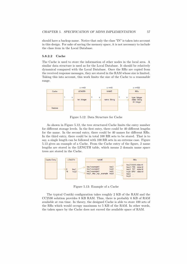
CHAPTER 5. SPECIFICATION OF MDNS IMPLEMENTATION 57
should have a backup name. Notice that only the class "IN" is taken into accountin this design. For sake of saving the memory space, it is not necessary to includethe class item in the Local Database.
5.8.2.2 Cache
The Cache is used to store the information of other nodes in the local area. Asimilar data structure is used as for the Local Database. It should be relativelydynamical compared with the Local Database. Once the RRs are copied fromthe received response messages, they are stored in the RAM whose size is limited.Taking this into account, this work limits the size of the Cache to a reasonablerange.
Figure 5.12: Data Structure for Cache
As shown in Figure 5.12, the tree structured Cache limits the entry numberfor different storage levels. In the first entry, there could be 40 different lengthsfor the name. In the second entry, there could be 40 names for different RRs.In the third entry, there could be in total 100 RR sets to be stored. That is tosay, a single length can be followed with 100 RR sets in an extreme case. Figure5.13 gives an example of a Cache. From the Cache entry of the figure, 2 namelengths are stored in the LENGTH table, which means 2 domain name spacetrees are stored in the Cache.
Figure 5.13: Example of a Cache
The typical Contiki configuration takes roughly 2 KB of the RAM and theCC2530 solution provides 8 KB RAM. Thus, there is probably 6 KB of RAMavailable at run time. In theory, the designed Cache is able to store 100 sets ofthe RRs which would occupy maximum to 5 KB of the RAM. In other words,the taken space by the Cache does not exceed the available space of RAM.
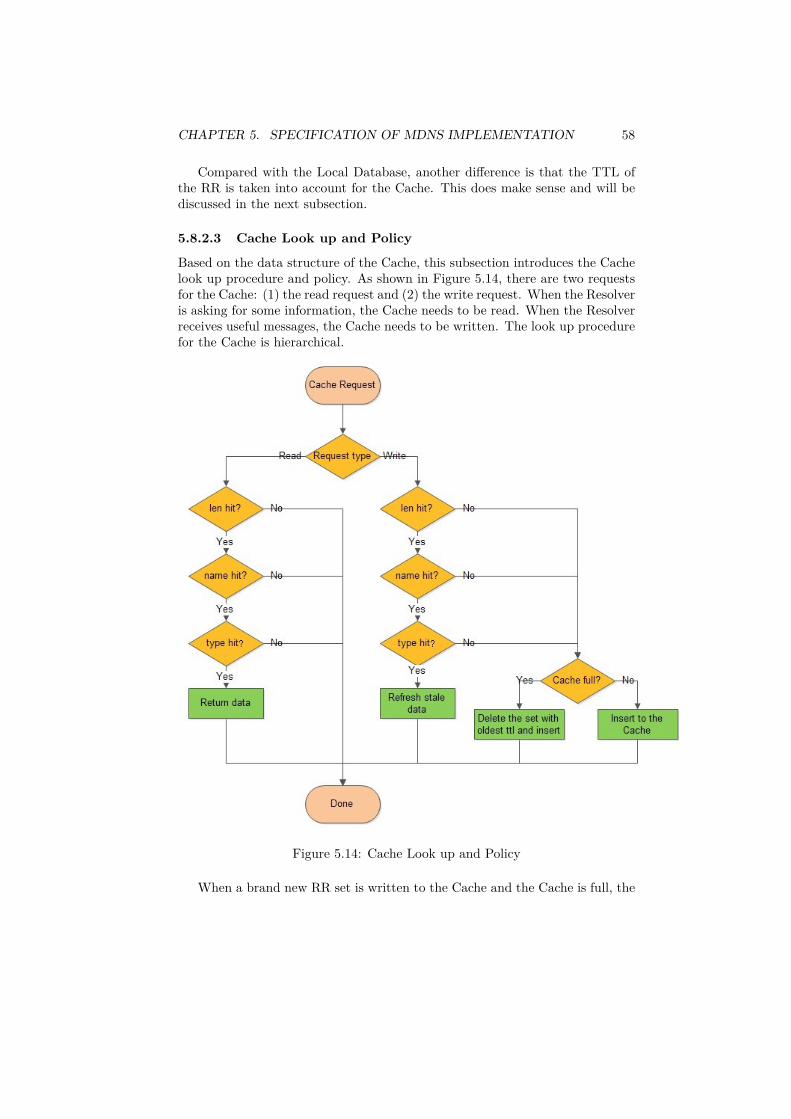
CHAPTER 5. SPECIFICATION OF MDNS IMPLEMENTATION 58
Compared with the Local Database, another difference is that the TTL ofthe RR is taken into account for the Cache. This does make sense and will bediscussed in the next subsection.
5.8.2.3 Cache Look up and Policy
Based on the data structure of the Cache, this subsection introduces the Cachelook up procedure and policy. As shown in Figure 5.14, there are two requestsfor the Cache: (1) the read request and (2) the write request. When the Resolveris asking for some information, the Cache needs to be read. When the Resolverreceives useful messages, the Cache needs to be written. The look up procedurefor the Cache is hierarchical.
Figure 5.14: Cache Look up and Policy
When a brand new RR set is written to the Cache and the Cache is full, the

CHAPTER 5. SPECIFICATION OF MDNS IMPLEMENTATION 59
mDNS Library will delete the RR set with the oldest ttl except for the length.If there are other names with the same length, this length entry should be kept.Otherwise it should be deleted. After that the new RR set should be insertedinto the Cache.
5.8.2.4 Internal APIs
As shown in Figure 5.1, there are interactions between the Cache and the Re-solver inside the mDNS Library. Normally, the Resolver processes the receivedmessage and stores the useful information in the Cache. On the other hand,the Resolver searches for the required information in the Cache when the in-ternal user program asks for it. This work provides the internal API betweenthe Cache and the Resolver. The first API listed below is used to search forthe useful information in the Cache and the second one is used to store theinformation in the Cache.
int mDNS_internal_Cache_Search (string out, string fqdn, stringtype);
@param out The string for the result of the required information. Itcould be the IPv6 address, the PTR record, the TXT record and the resultfor the service query. If the result does not exist in the mDNS environment,out will be empty.
@param fqdn It consists of two parts: the length and the name. Thesetwo parts will be searched in the Cache respectively.
@param type It is the type of the RRs, such as AAAA, PTR, TXTand SRV.
@return On success, return 0. On failure, return -1.
int mDNS_internal_Cache_Store (string fqdn, string type, stringrdata, int ttl);
@param fqdn It consists of two parts: the length and the name. Thesetwo parts will be stored in the Cache respectively.
@param type It is the type of the RRs, such as AAAA, PTR, TXTand SRV.
@param rdata It is the data of the RRs.@param ttl specifies the time interval that the RR may be cached before
the source of the information should again be consulted.@return On success, return 0. On failure, return -1.

CHAPTER 5. SPECIFICATION OF MDNS IMPLEMENTATION 60
5.9 Execution Scheme for the Contiki and themDNS Implementation
In this section, the basic execution scheme for the Contiki OS is introduced.Based on that, this work provides a potential solution for implementing themDNS service on the Contiki OS.
5.9.1 Event-driven Contiki KernelContiki kernel is event-based[15]. It means a process is invoked when the specificevents (e.g., the time-out) occur. Meanwhile, the process must not be blockedwhen it is activated. A detailed introduction to Contiki is given in Appendix A.
Compared with traditional multi-threading processes, the event-driven strat-egy has its own advantages, such as the low memory requirement. To be specific,the event-driven kernel only needs a single stack while the multi-threading ker-nel requires one stack for each individual thread. The low memory requirementmakes the event-driven kernel applicable for low-resource devices.
5.9.2 ProtothreadsProtothreads are lightweight stackless threads designed especially for the mem-ory constrained system[15]. So it is an ideal solution for the embedded system.Protothreads provide the linear code execution for event-driven systems imple-mented in the C language.
int a_protothread(struct pt *pt){PT_BEGIN(pt);/* ... */PT_WAIT_UNTIL(pt, condition1);/* ... */if(something) {
/* ... */PT_WAIT_UNTIL(pt, condition2);/* ... */
}PT_END(pt);
}
The example above shows the basic use of protothreads. It is obvious thatthe control flow in protothreads is sequential. Once a protothread is invoked, itis executing in sequence. It may be blocked somewhere until a certain conditionis satisfied. As shown in the example code, a thread is waiting for "condition1"as soon as it is started. Later it is blocked again until "condition2" is satisfiedand then continues. The programing constructs “if” and “while” are commonly
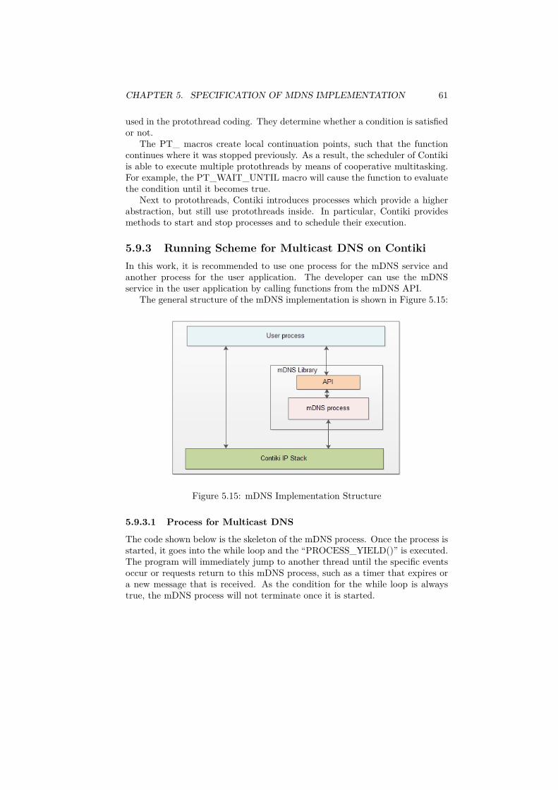
CHAPTER 5. SPECIFICATION OF MDNS IMPLEMENTATION 61
used in the protothread coding. They determine whether a condition is satisfiedor not.
The PT_ macros create local continuation points, such that the functioncontinues where it was stopped previously. As a result, the scheduler of Contikiis able to execute multiple protothreads by means of cooperative multitasking.For example, the PT_WAIT_UNTIL macro will cause the function to evaluatethe condition until it becomes true.
Next to protothreads, Contiki introduces processes which provide a higherabstraction, but still use protothreads inside. In particular, Contiki providesmethods to start and stop processes and to schedule their execution.
5.9.3 Running Scheme for Multicast DNS on ContikiIn this work, it is recommended to use one process for the mDNS service andanother process for the user application. The developer can use the mDNSservice in the user application by calling functions from the mDNS API.
The general structure of the mDNS implementation is shown in Figure 5.15:
Figure 5.15: mDNS Implementation Structure
5.9.3.1 Process for Multicast DNS
The code shown below is the skeleton of the mDNS process. Once the process isstarted, it goes into the while loop and the “PROCESS_YIELD()” is executed.The program will immediately jump to another thread until the specific eventsoccur or requests return to this mDNS process, such as a timer that expires ora new message that is received. As the condition for the while loop is alwaystrue, the mDNS process will not terminate once it is started.

CHAPTER 5. SPECIFICATION OF MDNS IMPLEMENTATION 62
PROCESS_THREAD(mDNS, ev, data) {PROCESS_BEGIN();while(1) {
PROCESS_YIELD();if(initialized) {
if(internal_query_received(ev)){mDNS_internal_Cache_Search (...);
}else if(mDNS_query_received(ev)) {
mDNS_internal_LocalDatabase_Search(...);}else (mDNS_response_received(ev)){
mDNS_internal_Cache_Store (...);}
}}PROCESS_END();
}
5.9.3.2 Process for the User Application
In order to use the mDNS service on the Contiki OS, this work suggests tocreate a user process. In the specific user space, the Contiki application can callthe mDNS API and make use of the mDNS service at any time.
PROCESS_THREAD(user, ev, data){PROCESS_BEGIN();Start_mDNS();
while(1) {PROCESS_PAUSE();/*...User Space...*/mDNS_internal_query(...);/*...User Space...*/
}PROCESS_END();
}
As shown above, the mDNS service is automatically started as soon as theprocess is started. Inside the “while” loop, the PROCESS_PAUSE() called toenable the cooperative multitasking and allow other processes, including themDNS process, to perform their task. The developer creates this own applica-tion in the user space by calling the mDNS API to get the required informationfrom the mDNS service, such as the link-local IP address of other devices in

CHAPTER 5. SPECIFICATION OF MDNS IMPLEMENTATION 63
the local network. Since the mDNS_internal_query function waits until itreceives a response from the mDNS process, the implementation uses the PRO-CESS_THREAD macro to create a local continuation point.

Chapter 6
Conclusion
This work mainly focuses on the design of implementing the mDNS protocol onlow-resource devices.
In Chapter 2 of the thesis, the concepts of IEEE 802.15.4, IPv6 and 6LoW-PAN are introduced. These issues are the hot topics for the development oflow-resource devices. Thus, this work chooses them as the basis for the designof mDNS implementation. To be specific, the Contiki OS and its applicablehardware platform CC2530, are used together as the target system in the de-sign. Since there are sufficient Contiki APIs which can be called by the OS, theunderlying layer is actually not directly related to the design, which facilitatesthe work. Nevertheless, the low computing capacity and the small memory aswell as the constraint for the MTU of the 802.15.4 packet should be taken intoaccount in the design.
As the basis of the IP networks, DNS plays an extremely important rolein the network operations. Multicast DNS, as an effective complement andextension for DNS, has significant research value. Multicast DNS realizes thename resolution and the DNS-like operation is executed on the local link in theabsence of any conventional DNS servers. There are no requirements for eitheradministration or configuration of the mDNS system. It is also unnecessaryto implement the mDNS service on the managed infrastructure. It is worthmentioning that Multicast DNS is not only applicable on the local link, but alsohas the potential for developing in a wider range of networks. All these conceptsare introduced in Chapter 3 and Chapter 4.
In Chapter 5, the APIs of Multicast DNS are taken as the start point ofthe design. In order to keep the consistency with the normal DNS system, theAPIs designed in this work are quite similar to the DNS resolver library onLinux. In order to reduce the complexity of the mDNS design in our practice,this work combines the Resolver and Server into a single library, called mDNSLibrary. A light-weighted design for the Local Database and the Cache is quiteessential for the mDNS implementation. In the design, a tree data structurewith hierarchical tables is applied. According to the flat structure of the localdomain name, this work uses the length of the domain name as the root of
64

CHAPTER 6. CONCLUSION 65
the tree structure, which improves the indexing efficiency. Moreover, neitherthe known-answer suppression nor the multi-packet known-answer suppressionis implemented in the design in order to minimize the size of the mDNS packet.This may potentially avoid the transmission problems in the IEEE 802.15.4multicast environment. Based on the target platform, this work provides apotential solution for implementing the mDNS design in the Contiki OS.

Appendix A
Contiki OS
Contiki is an open source, highly portable, multi-tasking operating system formemory-efficient network embedded systems and wireless sensor networks. Con-tiki has been used in a variety of projects, such as road tunnel fire monitoring,intrusion detection and wildlife monitoring[15].
Contiki is especially designed for low memory devices. A typical configura-tion of Contiki is 40 KB for ROM and 2 KB for RAM. This means very littlememory space is needed for the Contiki OS.
Contiki supports IP communication and both IPv4 and IPv6 can be appliedwith Contiki OS. In this work, IPv6 is chosen and Contiki is used as the targetplatform.
Contiki provides a convenient environment for the development of MulticastDNS, such as the complete Contiki APIs for application developers. In thiswork, mDNS service is recommended to call these system functions directlyfrom the application level. Thus, it is unnecessary to consider about the dataprocessing of the software stack, e.g., the compression scheme in the 6LoWPANadaptation layer.
A.1 Communication StackThere are two communication stacks inside the Contiki OS: µIP and Rime. Theapplication can choose any of them or even both. µIP is used for the communi-cation with Ethernet, while Rime is the stack designed for Low-power radio. Asshown in Figure A.1, when the datagram from application 1 is transmitted tothe Ethernet, it only goes through the µIP stack. If the datagram is transmittedto the low-power radio, it goes through µIP and Rime in order. Sometimes thedatagram from the application level can only go through the Rime stack only,and directly to the radio, such as application 3 in Figure A.1[25].
66

APPENDIX A. CONTIKI OS 67
Figure A.1: µIP and Rime
A.1.1 µIPv6µIPv6 is the IPv6 stack which consumes very little memory space. It is designedespecially for the operating system that runs on low-resource devices. It takesabout 11.5 KB for the code and requires no more than 2 KB of RAM. For thisreason, it is suitable for the constrained hardware platform. The µIPv6 stackis built on the top of the Contiki OS. With the latest Contiki version, IPv6 issupported for the target hardware platform.
µIPv6 does not depend on any particular MAC or link layer. The interfacebetween µIPv6 and lower layers consists of two wrappers for the link-layer in-put/output functions, the link-layer address, and a couple of constants. Thiscreates a level of abstraction which enables the easy integration of many differentMAC and link layer protocols[16], as shown in Figure A.2:
Figure A.2: uIPv6 stack
There is a particularly essential characteristic of the µIPv6 stack: for anyincoming and outgoing message, it only uses one global buffer to carry it. Thesize of the buffer is defined by the MAC header plus 1280 bytes. So different

APPENDIX A. CONTIKI OS 68
lower layers can give different buffer sizes. There could be additional buffers tosupport fragments reassembly if necessary.
For µIPv6, the main data structures are the interface address list and thecache storing the neighborhood devices, prefix list and default router list whichare required by the Neighbor Discovery. There are two periodic timers whichupdate the database and manage the data structure respectively.
A.1.2 RimeRime is a lightweight communication stack designed for the low-power radio.Rime provides a wide range of communication primitives which are suitablefor implementing communication-bound applications or network protocols. Allthese primitives are in a hierarchical structure, from a simple anonymous broad-caster to mesh network routing. A complex protocol consists of several simpleparts, where the more complex module makes use of the simpler ones. FigureA.3[25] lists the main modules:
Figure A.3: Overall Organization of Rime Stack
• abc: it represents the anonymous broadcast in the bottom level of theRime stack. The abc module receives all the packets coming from radiodriver and transmits them to the upper layer.
• broadcast: this module gives the source address to the outgoing packetand passes it to the abc module.

APPENDIX A. CONTIKI OS 69
• unicast: this module gives the destination address to the outgoing packetsand passes it to the broadcast module.
• multihop: when a packet is about to be sent, the multihop module asksthe route table for the next hop and sends this packet to it in the uni-cast way. When the multihop module receives the packet, if the currentnode is the destination, this packet should be transmitted to the upperlayer; otherwise the multihop module asks the next hop for the packet andtransmits it.
A.1.3 Contiki directory structureIn the Contiki OS distribution, there are 7 directories in total. Each directoryhas its own functionality.
• app/: there are several architecture independent applications inside theapp directory. Each subdirectory contains one application, such as ftp,telnet and web browser.
• core/: this directory includes the system source code. Each subdirectoryis for a different part of the system, such as lib, loader and net.
• cpu/: this directory includes all the CPU specific code in each subdirec-tory. It specifies the CPUs supported by Contiki, such as the CC2430,msp430 and x86.
• doc/: this directory includes all system documentation which describesthe system in text files.
• examples/: this directory includes some example project subdirectories.With these example projects, users can do some system tests and codemodifications.
• platforms/: this directory includes all the platforms supported by theContiki OS, such as the win32 and netsim.
• tools/: this directory contains the software for building the Contiki OSfor a specific platform.

Appendix B
CC2530EM
CC2530 is a true system-on-chip solution tailored for the IEEE 802.15.4, Zig-Bee, ZigBee RF4CE and Smart Energy applications[17]. In this project, theCC2530EM is used as the example hardware platform. This module can beused for RF remote control, building automation and industrial control andmonitoring.
Figure B.1: CC2530EM
The CC2530 chip has a large flash memory area. It combines a fully in-tegrated, high-performance 2.4GH RF transceiver with an 8051 MCU, 8KB ofRAM, up to 256 KB flash memory, and also other powerful supporting featuresand peripherals.
CC2530 has various operating modes. The transition time between operatingmodes is short, which ensures the low energy consumption for CC2530.
70

Appendix C
IAR Workbench
The commonly used Contiki version for CC2530 is compiled and debugged usingthe IAR Embedded Workbench for 8051[26]. Therefore, this work recommendsto choose the IAR workbench as the development tool.
There are many advantages of IAR workbench. IAR Embedded Workbenchwith its optimizing C/C++ compiler provides extensive support for a wide rangeof 8051 devices. There is an integrated development environment with projectmanagement tools and editor for the IAR. The optimizing compiler is able togenerate very compact and efficient code. A variety of configuration files for8051 devices from different manufacturers make the workbench meet multipleproducts requirements. In addition, ready-made examples and code templatesare included in the workbench.
71

Appendix D
SmartRF05EB
As shown in Figure D.1, the SmartRF05 Evaluation Board (SmartRF05EB)[27]is the motherboard in several development kits for the Low Power RF devicefrom Texas Instruments. SmartRF05EB is the platform for the evaluation mod-ule, such as CC2530. It can be connected to a PC via USB and controls theevaluation module. The board has several user interfaces and connections toexternal interfaces, which allow fast prototyping and testing of both softwareand hardware. This work suggests to choose SmartRF05EB as the motherboardfor the CC2530 evaluation module.
Figure D.1: SmartRF05EB
There are two main components on the board: the USB controller and theevaluation module. The USB controller and the evaluation module are con-nected with each other by using SPI, UART or the Debug Interface. The USBcontroller can access the UART RS232 interface, LCD, one LED, joystick andone button (USB button). The evaluation module can access the LCD, serialflash, four LEDs, 2 buttons, joystick and UART RS232 interface.
72

Appendix E
Test Setup
In order to test the mDNS design, this work provides a test environment. Asimple one hop 3-node example is recommended to be used. It means thereshould be three CC2530EM devices and the corresponding equipment includedin the test case. All the nodes should be within one hop distance from eachother. Routers are not considered in the test.
Figure E.1: Test for evaluation setup for the mDNS design
As shown in Figure E.1, a RS-232 cable is used to connect the evaluationboard with the PC during the test. All the information which is needed tobe tested can be shown on the PC monitor. The PC is used to monitor theincoming and outgoing information of the node1. The laptop is used to supply
73

APPENDIX E. TEST SETUP 74
the power for the SmartRF05EB and CC2530EM devices. As an alternativeoption, the SmartRF Protocol Packet Sniffer[37] can also be used to display RFpackets captured with a listening RF device, such as node1.
As introduced in Chapter 5, the mDNS API can be called by the user ap-plications. This work recommends to call the mDNS API in the user sectionwhich is shown in subsection 5.9.3.2 for the test cases. With the monitoring ofincoming and outgoing mDNS messages, the mDNS design can be tested.
This work does not provide the detailed test cases for the designed mDNSLibrary. It is recommended to test the design from two aspects: (1) the startupand (2) the name resolution. During the startup procedure, whether the mDNSservice starts successfully could be tested. As indicated in section 4.4, theProbing and Announcing steps should be tested properly, and Figure 4.4 couldbe used as the test sequence. The name conflict detection should be involvedin the startup test case. During the name resolution procedure, whether themDNS service works properly could be tested. Figure 5.2, 5.3, 5.5, 5.6 couldbe used as the test sequence for the whole name resolution process. Notice, ina full test, the interoperability of the mDNS Library and a library like Bonjouror Avahi should be tested as well.
Nomenclature
6LoWPAN IPv6 over Low power Wireless PersonalArea Networks (6LoWPAN) is a set ofstandards defined by Internet Engineer-ing Task Force (IETF), which createsand maintains all core Internet stan-dards and the architecture work. It wasdeveloped to enable the wireless net-work of embedded devices using sim-plified IPv6 functionalities, which takeinto account solve the limitation of em-bedded devices such as low power, smallmemory and limited bandwidth.
Ad-hoc It is a decentralized wireless network.Each node of an ad-hoc network be-haves as an end-point as well as a router.
CC2530 CC2530 is a system-on-chip solution tai-lored for the IEEE 802.15.4, Zig-Bee,ZigBee RF4CE and Smart Energy ap-plications.
Contiki OS Contiki is an open source, highly portable,multi-tasking operating system for memory-efficient network embedded systems andwireless sensor networks.
DNS The Domain Name System (DNS) isa hierarchical naming system built ondistributed databases for computers, ser-vices, or any resource connected to theInternet or a private network.
DNS SRV It is one kind of resource records ofDNS which is used for locating specificservices in a specific domain.
75

APPENDIX E. TEST SETUP 76
Fully Qualified Domain Name (FQDN) A fully qualified domain name (FQDN),sometimes also referred as an absolutedomain name, is a domain name thatspecifies its exact location in the treehierarchy of the Domain Name System(DNS).To be specific, it is the completedomain name for a specific computer,or host, on the Internet
IEEE 802.15.4 standard The IEEE 802.15.4 standard specifiesthe physical layer (PHY) and the me-dia access control (MAC) for low-ratewireless personal area networks.It is alow data-rate standard especially forlow power embedded devices with a lim-ited resource budget.
IPv6 IPv6 is a version of Internet Protocol(IP). It is responsible for routing pack-ets and it is developed to resolve limi-tations of IPv4, such as the limited ad-dress space.
Maximum Transmission Unit (MTU) In computer networking, the maximumtransmission unit (MTU) of a commu-nications protocol of a layer is the size(in bytes) of the largest protocol dataunit that the layer can pass onwards.
mDNS Library This work combines the name serverwith the resolver into a single library,named mDNS Library.
Multicast DNS Multicast DNS is a technology usingthe traditional DNS programming in-terface, packet formats and operatingsemantics, to replace the function ofthe conventional DNS server, especiallyin small area networks. It is a promis-ing technology chosen to implement ser-vice discovery for wireless ad-hoc net-works.
Name Server A name server is a server program whichhold information about the domain tree’sstructure.
POPO
Rectangle

APPENDIX E. TEST SETUP 77
Personal Area Network (PAN) The PAN is used for interconnectingdevices around an individual person’sworkspace.
Protothreads Protothreads are lightweight stacklessthreads designed especially for the mem-ory constrained system.
Querier The functional part of the DNS/mDNSgenerates the DNS/mDNS query.
Resolver The user programs access name serversthrough standard programs called re-solvers.
Resource Records (RRs) RRs hold the information for the corre-sponding domain and all the informa-tion stored in the zone files of the DNS.
Responder The functional part of the DNS/mDNSgenerates the DNS/mDNS response.
Service discovery It is an important addition to ad-hocnetworks since it enables sharing of func-tionality and resources and makes itpossible to run distributed applicationswithout the need for manual installa-tion and maintenance of a service database.
POPO
Rectangle

Bibliography
[1] S. Cheshire and M. Krochmal. Internet-Draft: Mul-ticast DNS. http://files.multicastdns.org/draft-cheshire-dnsext-multicastdns.txt, Feb 14, 2011.
[2] P. Mockapetris. Domain Names - Implementation and Specifica-tion. RFC 1035, November 1987.
[3] P. Mockapetris. Domain Names - Concepts and Facilities. RFC1034, November 1987.
[4] S. Cheshire and M. Krochmal. Internet-Draft: DNS-Based Service Discovery. http://files.dns-sd.org/draft-cheshire-dnsext-dns-sd.txt, Feb 27, 2011.
[5] A. Gulbrandsen, P. Vixie and L. Esibov. A DNS RR for specifyingthe location of services (DNS SRV). RFC 2782, Febrary, 2000.
[6] S. Cheshire. Zero Configuration Networking (Zeroconf). http://www.zeroconf.org/, September, 2011.
[7] Olafur Gudmundsson, Andrew Sullivan. DNS Extensions (dnsext).http://datatracker.ietf.org/wg/dnsext/charter/, Novem-ber, 2011.
[8] S. Cheshire. Multicast DNS. http://www.multicastdns.org/,September, 2011.
[9] Internet Systems Consortium. BIND 9 Administrator ReferenceManual. http://www.bind9.net/arm97.pdf, 2010.
[10] Zach Shelby and Carsten Bormann. 6LoWPAN: The Wireless Em-bedded Internet. A John Wiley and Sons, Ltd, Publication, 2009.
[11] Atmel. IEEE 802.15.4 MAC - User Guide. http://www.atmel.com/dyn/resources/prod_documents/doc5182.pdf. Sep, 2006.
[12] Günter Obiltschnig. Automatic Configuration and Service Discov-ery for Networked Smart Devices. Electronica Embedded Confer-ence Munich, 2006.
78

BIBLIOGRAPHY 79
[13] S. Thomson, T. Narten and T. Jinmei. IPv6 Stateless AddressAutoconfiguration. RFC 4862, September 2007.
[14] G. Montenegro, N. Kushalnagar, J. Hui and D. Culler. Transmis-sion of IPv6 Packets over IEEE 802.15.4 Networks. RFC 4944,September 2007.
[15] Adam Dunkels. The Contiki OS: The Operating System for theInternet of Things. http://www.sics.se/contiki/, May, 2011
[16] Mathilde Durvy, Julien Abeillé, Patrick Wetterwald, ColinO’Flynn, Blake Leverett, Eric Gnoske, Michael Vidales, Geoff Mul-ligan, Nicolas Tsiftes, Niclas Finne, Adam Dunkels. Poster Ab-stract: Making Sensor Networks IPv6 Ready. Nov, 2008.
[17] TI. A True System-on-Chip Solution for 2.4-GHz IEEE802.15.4 and ZigBee Applications. http://focus.ti.com/lit/ds/symlink/cc2530.pdf. Feb, 2011.
[18] P. Thubert. Internet-Draft: Compression Format for IPv6 Data-grams in Low Power and Lossy Networks. http://tools.ietf.org/pdf/draft-ietf-6lowpan-hc-15.pdf, February 24, 2011.
[19] S. Deering, R. Hinden. Internet Protocol, Version 6 (IPv6) Speci-fication. RFC 2460, December, 1998.
[20] S. C. Ergen. IEEE 802.15.4 Summary, Technical Report, AdvancedTechnology Lab of National Semiconductor, August 2004.
[21] B. Patil, F. Xia and B. Sarikaya. Transmission of IPv6 via theIPv6 Convergence Sublayer over IEEE 802.16 Networks. RFC 5121,February 2008.
[22] J. Postel. User Datagram Protocol. RFC 768, August, 1980.
[23] Apple Inc. Introduction to Bonjour Overview. http://developer.apple.com/library/mac/#documentation/Cocoa/Conceptual/NetServices/Introduction.html#//apple_ref/doc/uid/10000119i, March, 2011.
[24] Lennart Poettering, Trent Lloyd, Sjoerd Simons. Avahi. http://avahi.org/, April, 2011.
[25] Adam Dunkels. Contiki - Crash Course. http://www.ee.kth.se/~mikaelj/wsn_course/contiki-course-kth-9oct2008-draft.pdf, October, 2008.
[26] IAR Systems AB. IAR Embedded Workbench ® IDE User Guide.http://supp.iar.com/FilesPublic/UPDINFO/004919/EWSH_UserGuide.pdf, Febrary, 2010.

BIBLIOGRAPHY 80
[27] TI. SmartRF05 Evaluation Board User’s Guide. http://www.ti.com/lit/ug/swru210a/swru210a.pdf, 2010.
[28] John D. Day and Hubert Zimmermann. The OS1 Reference Model.Proceedings of the IEEE, 1983.
[29] R. Droms. Dynamic Host Configuration Protocol. RFC 2131,March, 1997.
[30] Jonathan B. Postel. Simple Mail Transfer Protocol. RFC 821, Au-gust, 1982.
[31] R. Fielding, J. Gettys, J. Mogul, L. Masinter, P. Leach, T. Berners-Lee. Hypertext Transfer Protocol – HTTP/1.1. RFC 2616, June,1999.
[32] Jonathan Hui, David Culler, Berkeley Samita Chakrabarti. 6LoW-PAN: Incorporating IEEE 802.15.4 into the IP architecture. In-ternet Protocol for Smart Objects (IPSO) Alliance White Paper,January, 2009.
[33] Altera Corporation. Direct Sequence Spread Spectrum (DSSS) Mo-dem Reference Design. Altera Application Note 289, April, 2003.
[34] Jin-Shyan Lee. An Experiment on Performance Study of IEEE802.15.4 Wireless Networks. IEEE International Conference onEmerging Technologies and Factory Automation, September, 2005.
[35] A. Conta, Lucent, S. Deering. Internet Control Message Protocol(ICMPv6) for the Internet Protocol Version 6 (IPv6) Specification.RFC 2463, December, 1998.
[36] Tanır Özçelebi. Computer Networks 2IC15Application Layer.TU/e Computer Science, System Architecture and NetworkingSlides, April, 2011.
[37] TI. SmartRF™ Packet Sniffer User Manual. http://www.ti.com/lit/ug/swru187f/swru187f.pdf, 2010.
Related Documents


![[Attack]tive Directory - Triangle InfoSeCon€¦ · Network -> DNS ClientEnable Turn Off Multicast Name Resolution ⬡NBT-NS: Network Connection Properties -> TCP/IPv4 -> Advanced,](https://static.cupdf.com/doc/110x72/5fcd3f035c0dfe081447abce/attacktive-directory-triangle-infosecon-network-dns-clientenable-turn.jpg)