List o f pages in this Trip Kit Trip Kit Index Airport Information Fo r EHAM Terminal Charts For EHAM Revision Letter For Cycle 03-201 4 Change Notices Notebook T rip Kit Index Printed on 16 Apr 2014 Page 1 (c) JEPPESEN SANDERSON, INC., 2014, ALL RIGHTS RESERVED j e p =J EP P ES EN JeppV iew for Wind ow s

Welcome message from author
This document is posted to help you gain knowledge. Please leave a comment to let me know what you think about it! Share it to your friends and learn new things together.
Transcript

8/10/2019 EHAM Charts
http://slidepdf.com/reader/full/eham-charts 1/114
List of pages in this Trip Kit
Trip Kit Index
Airport Information For EHAMTerminal Charts For EHAMRevision Letter For Cycle 03-2014Change NoticesNotebook
p Kit Indexnted on 16 Apr 2014ge 1JEPPESEN SANDERSON, INC., 2014, ALL RIGHTS RESERVED
jep=J E P P E S E N
JeppView for Windows

8/10/2019 EHAM Charts
http://slidepdf.com/reader/full/eham-charts 2/114
General Information
Location: Amsterdam Nld
IATA Code: AMSLat/Long: N52° 18.5' E004° 45.8'Elevation: -11 ft
Airport Use: PublicMagnetic Variation: 0.5°E
Fuel Types: Jet, Jet A-1Repair Types: Major Airframe, Major EngineCustoms: Yes
Airport Type: IFRLanding Fee: YesControl Tower: YesJet Start Unit: NoLLWS Alert: NoBeacon: NoPattern Altitude: 1011 ft AGL
Sunrise: 0442 ZSunset: 1840 Z,
Runway Information
Runway: 04Length x Width: 6608 ft x 148 ftSurface Type: asphaltTDZ-Elev: -13 ftLighting: Edge, ALS
Runway: 06Length x Width: 11483 ft x 148 ft
Surface Type: asphaltTDZ-Elev: -11 ftLighting: Edge, ALS, Centerline, TDZDisplaced Threshold: 820 ft
Runway: 09Length x Width: 11329 ft x 148 ftSurface Type: asphaltTDZ-Elev: -12 ftLighting: Edge, CenterlineDisplaced Threshold: 295 ft
Runway: 18CLength x Width: 10827 ft x 148 ftSurface Type: asphaltTDZ-Elev: -12 ft
Lighting: Edge, ALS, Centerline, TDZ
Runway: 18LLength x Width: 11155 ft x 148 ftSurface Type: asphaltTDZ-Elev: -12 ftLighting: Edge, CenterlineDisplaced Threshold: 1887 ft
Runway: 18RLength x Width: 12467 ft x 197 ftSurface Type: asphaltTDZ-Elev: -13 ftLighting: Edge, ALS, Centerline, TDZDisplaced Threshold: 886 ft
Runway: 22Length x Width: 6608 ft x 148 ftSurface Type: asphaltTDZ-Elev: -14 ftLighting: Edge, ALS
Runway: 24Length x Width: 11483 ft x 148 ftSurface Type: asphaltTDZ-Elev: -12 ftLighting: Edge, Centerline
Runway: 27Length x Width: 11329 ft x 148 ftSurface Type: asphaltTDZ-Elev: -12 ftLighting: Edge, ALS, Centerline, TDZ
Runway: 36CLength x Width: 10827 ft x 148 ft
Surface Type: asphaltTDZ-Elev: -12 ftLighting: Edge, ALS, Centerline, TDZDisplaced Threshold: 1477 ft
Runway: 36LLength x Width: 12467 ft x 197 ftSurface Type: asphaltTDZ-Elev: -12 ftLighting: Edge, Centerline
Runway: 36RLength x Width: 11155 ft x 148 ftSurface Type: asphaltTDZ-Elev: -11 ftLighting: Edge, ALS, Centerline, TDZ
Communication Information
ATIS 132.975 Arrival Service ATIS 131.35 ATIS 122.2 Departure Service ATIS 108.4 Arrival ServiceSchiphol Start-Up Tower 121.65Schiphol Tower 119.9Schiphol Tower 119.225Schiphol Tower 118.95Schiphol Tower 118.275Schiphol Tower 118.1Schiphol Tower 36.23 MilitarySchiphol Ground Control 122.425Schiphol Ground Control 121.9Schiphol Ground Control 121.8Schiphol Ground Control 121.7Schiphol Clearance Delivery 121.975Schiphol Approach Control 126.675Schiphol Approach Control 121.2Schiphol Approach Control 119.05Schiphol Approach Control 118.075 SecondarySchiphol Approach Control 36.93 MilitarySchiphol Arrival Control 131.15Schiphol Arrival Control 118.4Schiphol Departure Control 118.075 Secondary
Schiphol Departure Control 121.2Schiphol Departure Control 119.05Schiphol Departure Control 36.93 Military
Amsterdam Radar 134.375 Amsterdam Radar 130.95 Amsterdam Radar 120.55 Amsterdam Radar 118.8
General Information
Location: Amsterdam Nld
IATA Code: AMSLat/Long: N52° 18.5' E004° 45.8'Elevation: -11 ft
Airport Use: PublicMagnetic Variation: 0.5°E
Fuel Types: Jet, Jet A-1Repair Types: Major Airframe, Major EngineCustoms: Yes
Airport Type: IFRLanding Fee: YesControl Tower: YesJet Start Unit: NoLLWS Alert: NoBeacon: NoPattern Altitude: 1011 ft AGL
Sunrise: 0442 ZSunset: 1840 Z,
Runway Information
Runway: 04Length x Width: 6608 ft x 148 ftSurface Type: asphaltTDZ-Elev: -13 ftLighting: Edge, ALS
Runway: 06Length x Width: 11483 ft x 148 ft
Surface Type: asphaltTDZ-Elev: -11 ftLighting: Edge, ALS, Centerline, TDZDisplaced Threshold: 820 ft
Runway: 09Length x Width: 11329 ft x 148 ftSurface Type: asphaltTDZ-Elev: -12 ftLighting: Edge, CenterlineDisplaced Threshold: 295 ft
Runway: 18CLength x Width: 10827 ft x 148 ftSurface Type: asphaltTDZ-Elev: -12 ft
rport Information For EHAMnted on 16 Apr 2014ge 1JEPPESEN SANDERSON, INC., 2014, ALL RIGHTS RESERVED
jep=J E P P E S E N
JeppView for Windows

8/10/2019 EHAM Charts
http://slidepdf.com/reader/full/eham-charts 3/114
General Information
Location: Amsterdam Nld
IATA Code: AMSLat/Long: N52° 18.5' E004° 45.8'Elevation: -11 ft
Airport Use: PublicMagnetic Variation: 0.5°E
Fuel Types: Jet, Jet A-1Repair Types: Major Airframe, Major EngineCustoms: Yes
Airport Type: IFRLanding Fee: YesControl Tower: YesJet Start Unit: NoLLWS Alert: NoBeacon: NoPattern Altitude: 1011 ft AGL
Sunrise: 0442 ZSunset: 1840 Z,
Runway Information
Runway: 04Length x Width: 6608 ft x 148 ftSurface Type: asphaltTDZ-Elev: -13 ftLighting: Edge, ALS
Runway: 06Length x Width: 11483 ft x 148 ft
Surface Type: asphaltTDZ-Elev: -11 ftLighting: Edge, ALS, Centerline, TDZDisplaced Threshold: 820 ft
Runway: 09Length x Width: 11329 ft x 148 ftSurface Type: asphaltTDZ-Elev: -12 ftLighting: Edge, CenterlineDisplaced Threshold: 295 ft
Runway: 18CLength x Width: 10827 ft x 148 ftSurface Type: asphaltTDZ-Elev: -12 ft
Lighting: Edge, ALS, Centerline, TDZ
Runway: 18LLength x Width: 11155 ft x 148 ftSurface Type: asphaltTDZ-Elev: -12 ftLighting: Edge, CenterlineDisplaced Threshold: 1887 ft
Runway: 18RLength x Width: 12467 ft x 197 ftSurface Type: asphaltTDZ-Elev: -13 ftLighting: Edge, ALS, Centerline, TDZDisplaced Threshold: 886 ft
Runway: 22Length x Width: 6608 ft x 148 ftSurface Type: asphaltTDZ-Elev: -14 ftLighting: Edge, ALS
Runway: 24Length x Width: 11483 ft x 148 ftSurface Type: asphaltTDZ-Elev: -12 ftLighting: Edge, Centerline
Runway: 27Length x Width: 11329 ft x 148 ftSurface Type: asphaltTDZ-Elev: -12 ftLighting: Edge, ALS, Centerline, TDZ
Runway: 36CLength x Width: 10827 ft x 148 ft
Surface Type: asphaltTDZ-Elev: -12 ftLighting: Edge, ALS, Centerline, TDZDisplaced Threshold: 1477 ft
Runway: 36LLength x Width: 12467 ft x 197 ftSurface Type: asphaltTDZ-Elev: -12 ftLighting: Edge, Centerline
Runway: 36RLength x Width: 11155 ft x 148 ftSurface Type: asphaltTDZ-Elev: -11 ftLighting: Edge, ALS, Centerline, TDZ
Communication Information
ATIS 132.975 Arrival Service ATIS 131.35 ATIS 122.2 Departure Service ATIS 108.4 Arrival ServiceSchiphol Start-Up Tower 121.65Schiphol Tower 119.9Schiphol Tower 119.225Schiphol Tower 118.95Schiphol Tower 118.275Schiphol Tower 118.1Schiphol Tower 36.23 MilitarySchiphol Ground Control 122.425Schiphol Ground Control 121.9Schiphol Ground Control 121.8Schiphol Ground Control 121.7Schiphol Clearance Delivery 121.975Schiphol Approach Control 126.675Schiphol Approach Control 121.2Schiphol Approach Control 119.05Schiphol Approach Control 118.075 SecondarySchiphol Approach Control 36.93 MilitarySchiphol Arrival Control 131.15Schiphol Arrival Control 118.4Schiphol Departure Control 118.075 Secondary
Schiphol Departure Control 121.2Schiphol Departure Control 119.05Schiphol Departure Control 36.93 Military
Amsterdam Radar 134.375 Amsterdam Radar 130.95 Amsterdam Radar 120.55 Amsterdam Radar 118.8
Lighting: Edge, ALS, Centerline, TDZ
Runway: 18LLength x Width: 11155 ft x 148 ftSurface Type: asphaltTDZ-Elev: -12 ftLighting: Edge, CenterlineDisplaced Threshold: 1887 ft
Runway: 18RLength x Width: 12467 ft x 197 ftSurface Type: asphaltTDZ-Elev: -13 ftLighting: Edge, ALS, Centerline, TDZDisplaced Threshold: 886 ft
Runway: 22Length x Width: 6608 ft x 148 ftSurface Type: asphaltTDZ-Elev: -14 ftLighting: Edge, ALS
Runway: 24Length x Width: 11483 ft x 148 ftSurface Type: asphaltTDZ-Elev: -12 ftLighting: Edge, Centerline
Runway: 27Length x Width: 11329 ft x 148 ftSurface Type: asphaltTDZ-Elev: -12 ftLighting: Edge, ALS, Centerline, TDZ
Runway: 36CLength x Width: 10827 ft x 148 ft
Surface Type: asphaltTDZ-Elev: -12 ftLighting: Edge, ALS, Centerline, TDZDisplaced Threshold: 1477 ft
Runway: 36LLength x Width: 12467 ft x 197 ftSurface Type: asphaltTDZ-Elev: -12 ftLighting: Edge, Centerline
Runway: 36RLength x Width: 11155 ft x 148 ftSurface Type: asphaltTDZ-Elev: -11 ftLighting: Edge, ALS, Centerline, TDZ
rport Information For EHAMnted on 16 Apr 2014ge 2JEPPESEN SANDERSON, INC., 2014, ALL RIGHTS RESERVED
jep=J E P P E S E N
JeppView for Windows

8/10/2019 EHAM Charts
http://slidepdf.com/reader/full/eham-charts 4/114
General Information
Location: Amsterdam Nld
IATA Code: AMSLat/Long: N52° 18.5' E004° 45.8'Elevation: -11 ft
Airport Use: PublicMagnetic Variation: 0.5°E
Fuel Types: Jet, Jet A-1Repair Types: Major Airframe, Major EngineCustoms: Yes
Airport Type: IFRLanding Fee: YesControl Tower: YesJet Start Unit: NoLLWS Alert: NoBeacon: NoPattern Altitude: 1011 ft AGL
Sunrise: 0442 ZSunset: 1840 Z,
Runway Information
Runway: 04Length x Width: 6608 ft x 148 ftSurface Type: asphaltTDZ-Elev: -13 ftLighting: Edge, ALS
Runway: 06Length x Width: 11483 ft x 148 ft
Surface Type: asphaltTDZ-Elev: -11 ftLighting: Edge, ALS, Centerline, TDZDisplaced Threshold: 820 ft
Runway: 09Length x Width: 11329 ft x 148 ftSurface Type: asphaltTDZ-Elev: -12 ftLighting: Edge, CenterlineDisplaced Threshold: 295 ft
Runway: 18CLength x Width: 10827 ft x 148 ftSurface Type: asphaltTDZ-Elev: -12 ft
Lighting: Edge, ALS, Centerline, TDZ
Runway: 18LLength x Width: 11155 ft x 148 ftSurface Type: asphaltTDZ-Elev: -12 ftLighting: Edge, CenterlineDisplaced Threshold: 1887 ft
Runway: 18RLength x Width: 12467 ft x 197 ftSurface Type: asphaltTDZ-Elev: -13 ftLighting: Edge, ALS, Centerline, TDZDisplaced Threshold: 886 ft
Runway: 22Length x Width: 6608 ft x 148 ftSurface Type: asphaltTDZ-Elev: -14 ftLighting: Edge, ALS
Runway: 24Length x Width: 11483 ft x 148 ftSurface Type: asphaltTDZ-Elev: -12 ftLighting: Edge, Centerline
Runway: 27Length x Width: 11329 ft x 148 ftSurface Type: asphaltTDZ-Elev: -12 ftLighting: Edge, ALS, Centerline, TDZ
Runway: 36CLength x Width: 10827 ft x 148 ft
Surface Type: asphaltTDZ-Elev: -12 ftLighting: Edge, ALS, Centerline, TDZDisplaced Threshold: 1477 ft
Runway: 36LLength x Width: 12467 ft x 197 ftSurface Type: asphaltTDZ-Elev: -12 ftLighting: Edge, Centerline
Runway: 36RLength x Width: 11155 ft x 148 ftSurface Type: asphaltTDZ-Elev: -11 ftLighting: Edge, ALS, Centerline, TDZ
Communication Information
ATIS 132.975 Arrival Service ATIS 131.35 ATIS 122.2 Departure Service ATIS 108.4 Arrival ServiceSchiphol Start-Up Tower 121.65Schiphol Tower 119.9Schiphol Tower 119.225Schiphol Tower 118.95Schiphol Tower 118.275Schiphol Tower 118.1Schiphol Tower 36.23 MilitarySchiphol Ground Control 122.425Schiphol Ground Control 121.9Schiphol Ground Control 121.8Schiphol Ground Control 121.7Schiphol Clearance Delivery 121.975Schiphol Approach Control 126.675Schiphol Approach Control 121.2Schiphol Approach Control 119.05Schiphol Approach Control 118.075 SecondarySchiphol Approach Control 36.93 MilitarySchiphol Arrival Control 131.15Schiphol Arrival Control 118.4Schiphol Departure Control 118.075 Secondary
Schiphol Departure Control 121.2Schiphol Departure Control 119.05Schiphol Departure Control 36.93 Military
Amsterdam Radar 134.375 Amsterdam Radar 130.95 Amsterdam Radar 120.55 Amsterdam Radar 118.8
rport Information For EHAMnted on 16 Apr 2014ge 3JEPPESEN SANDERSON, INC., 2014, ALL RIGHTS RESERVED
jep=J E P P E S E N
JeppView for Windows

8/10/2019 EHAM Charts
http://slidepdf.com/reader/full/eham-charts 5/114
,SCHI PHOL . AI RPORT.BRI EFI NG.
+ J E P P E S E N
1.1. ATISD-ATIS Arr iva l 108.4 132.97D-ATIS Departure 122.2
1.2. NOISE ABATEMENT PROCEDURES1.2.1. GENERAL
A ll procedur es have proved t o be hi ghl y ef f i cient i n respect of noise abat ementand ACFT shal l adhere t o t hese, except f or saf ety r easons or w hen ot her w i seinstructed by ATC.
1.2.2. ACFT CLASSIFIED ACCORDING TO ICAO ANNEX 16Take-off and landi ng are not al l owed f or Chapter 2 A CFT.
Chapter 3 A CFT f or w hich t he margi n of t he sum of t he t hree cer t i f i cat i on noiselevels , r elat i ve t o the sum of t he t hree appli cable ICAO A nnex 16 Chapter 3 cer-t i f i cat i on noise l i mi t s , i s less than 5 EPNdB t he f ol l owi ng appli es:
- New o per a t i ons a r e not a l l o w e d.
- For A CFT equi pped w i t h engines w i t h bypass ra t i o smal le r o r equa l 3 , t ake-offand landi ng is not al l ow ed bet w een 1800-0800LT.
- For A CFT equi pped w i t h engines w i t h bypass ra t i o grea te r t han 3 , i t i s no tal l owed t o plan take-of f bet w een 2300-0700LT.
1.2. 3. PREFERENTIA L RWY SYSTEM1.2.3.1. GENERAL
The RW Ys i n use wi l l be select ed by A TC accordi ng t o a pref erent i al RW Y syst em.
The pref erent i al sequence is subject t o noi se load development s and may t her e-f ore change in any gi ven per i od. Devi at i ons f r om t he pref erent i al sequence f orselect i ng RW Ys i n use can be made by A TC:
- When approach f aci l i t i es on t he se lect ed RWY are no t sui t able f or opera t i onsi n the prevai l i ng weather .
- When crosswi nd component s do not meet t he gi ven l i mi t s for any RWYcombinat ion.
- When est i mated sur f ace f r i c t i on on RWYs i s below cer t a in st andards .
- When heavy showers a re observed or w i nd shear i s r epor t ed i n t he v ic in i t y oft he APT.
The use of a non-pref erent i al RW Y f or t ake-off and landing i s not per mi t t edunl ess specif i cal l y r equested f or saf ety r easons by t he pi l ot .
However, i f a pi l ot decides t hat a dif f erent landing RW Y should be used f or
saf e ty r easons , A TC wi l l ass ign t ha t RWY (a i r t r a ff i c or o ther condi t i onspe rm i t t i ng ) .
1.2.3.2. WIND CRITERIAI n select i ng t he RWY combinat i on t o be used f r om t he pr efer ent i al RWY syst em,A TC shal l apply t he w i nd speed cr i t er i a as have been st at ed i n the t able below .
I n applyi ng t hese wi nd cr i t er i a , gusts below 10 KT shal l not be taken int o account .
I f t he act ual w i nd speed values exceed t he w i nd speed cr i t er i a , A TC may applyhigher cr osswi nd and/ or t ai lw i nd values in order t o assign a RW Y combinat i on.
A ccept i ng a RW Y i s a pi l ot ' s deci sion. I f a pi lot , pr ompt ed by saf ety concer ns,r equests anot her RW Y f or l anding, t his r equest w i l l be granted w hen possible . I nt ha t case, t he pi lo t mus t submi t a wr i t t en repor t ( t he oper a tor i s respons ib le forproper r eport i ng pr ocedures) .
10-1P3 JAN 14 .Ef f . 9.Jan.
1. GENERAL
| JEPPESEN, 2005, 2013. A LL RI GHTS RESERVED.
8/10/2019 EHAM Charts
http://slidepdf.com/reader/full/eham-charts 6/114
,SCHI PHOL .AI RPORT.BRI EFI NG.
+ J E P P E S E N
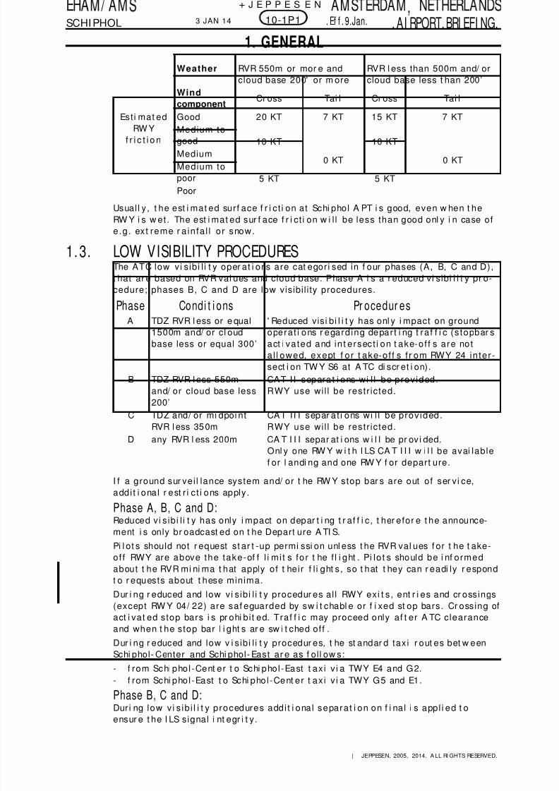
Usuall y, t he est i mat ed surf ace f r i ct i on at Schi phol A PT i s good, even w hen t heRW Y i s w et . The est i mat ed sur f ace f r i ct i on w i l l be less than good onl y i n case ofe .g . ex t reme r a infa l l o r snow.
1.3. LOW VISIBILITY PROCEDURESThe ATC low vi sibi l i t y oper at i ons are cat egori sed in f our phases (A, B, C and D),t hat ar e based on RVR val ues and cloud base. Phase A i s a r educed vi sibi l i t y pr o-cedure; phases B, C and D are low visibility procedures.
I f a ground sur vei l lance system and/ or t he RW Y stop bar s are out of ser vi ce,addi t i ona l r est r i c t i ons apply.
Phase A, B, C and D:Reduced vi sibi l i t y has only i mpact on depar t i ng t r af f i c , t her efor e t he announce-
ment i s only br oadcast ed on t he Depart ure A TI S.Pi l ot s should not r equest st ar t -up permi ssi on unl ess t he RVR val ues f or t he t ake-off RWY are above the take-of f l i mi t s for t he f l i ght . Pi lo t s should be i nf ormedabout t he RVR mi ni ma t hat apply of t heir f l i ght s , so t hat t hey can r eadi ly r espondt o r equests about t hese minima.
Dur i ng r educed and low vi sibi l i t y procedur es al l RWY exi t s , ent r i es and cr ossings(except RW Y 04/ 22) are saf eguarded by sw i t chabl e or f i xed st op bars . Cr ossing ofact i vat ed s top bars i s pr ohi bi t ed. Traf f i c may proceed only af t er A TC clearanceand when t he s top bar l i ght s ar e sw i t ched off .
Dur i ng r educed and low v i sibi l i t y procedur es, t he st andar d taxi r out es bet w eenSchi phol- Center and Schi phol- East ar e as f oll ow s:
- f rom Schi phol -Cent er t o Schi phol -East t ax i v i a TWY E4 and G2.- f rom Schi phol -East t o Schi phol -Cent er t ax i v i a TWY G5 and E1.
Phase B, C and D:Duri ng low v i s ib i l i t y procedures addi t i ona l separa t i on on f i na l i s appl i ed t oensur e t he I LS signal i nt egr i t y.
Weather RVR 550m or mor e andcloud base 200' or m ore
RVR l ess than 500m and/ orcloud base less t han 200’
Windcomponent
Cr oss Tai l Cr oss Tai l
Est i mat edRW Y
f r i c t i o n
Good 20 KT 7 KT 15 KT 7 KT
Medium togood 10 KT
0 KT
10 KT
0 KTMediumMedium topoor 5 KT 5 KTPoor
Phase Condi t i ons Pr ocedur esA TDZ RVR l ess or e qual
1500m and/ or cl oudbase less or equal 300’
' Reduced visi bi l i t y has onl y i mpact on groundopera t i ons r egard ing depar t i ng t ra f f i c ( s topbar sact i va ted and in t e rsec t i on t ake-off s a re no ta l l owed, exept f or t ake-off s f r om RWY 24 in te r-sect i on TW Y S6 at A TC di scr et i on).
B TDZ RVR l ess 550mand/ or cloud base less
200’
CAT I I separa t i ons wi l l be provided .RWY use wil l be restr icted.
C TDZ and/ or mi dpoi ntRVR l ess 350m
CAT I I I separ a t i ons wi l l be provided .RWY use wil l be restr icted.
D any RVR l ess 200m CAT I I I separ at i ons w i l l be pr ovi ded.Onl y one RW Y w i t h I LS CA T I I I w i l l be avai lablef or l andi ng and one RW Y f or depart ure.
10-1P13 JAN 14 .Ef f . 9.Jan.
1. GENERAL
| JEPPESEN, 2005, 2014. A LL RI GHTS RESERVED.

8/10/2019 EHAM Charts
http://slidepdf.com/reader/full/eham-charts 7/114
,SCHI PHOL . AI RPORT.BRI EFI NG.
+ J E P P E S E N
Phase C and D:Taxi guidance based on ground surveillance information will be provided (sharedpil ot / A TC r esponsi bi l i t y f or r out i ng and avoidance of i nadvert ent RW Y ent r y) .
On t he tax i w ays East of RW Y 18L/ 36R (ex cept TWY E4 and TW Y N1) A CFT shal l betowed or guided by a fol low-me car.
A vai l abi l i t y of t he K-apron f or park i ng and depar t ure opera t i ons i s l i mi t ed. Occa-sional i nbound t r af f i c shal l , upon recei vi ng clearance fr om Ground Cont r ol , bet owed or gui ded by a f ol l ow- me car t o the apr on ent r y GL.
Phase D:I f t he RVR val ues dr op below 200m and t he ground surv eil l ance inf r ast r uct ure hasdegraded to an unacceptable level , the APT wil l ul t imately be closed for al l t raf-f i c (A TI S/ RTF:" SCHI PHOL below operat i onal l i mi t s" ) .
1. 4. SURFACE MOVEMENT GUIDANCE AND CONTROL SYSTEM1.4.1. OPERATION OF MODE S TRANSPONDER WHEN ACFT IS ON GROUND
A CFT oper at ors should ensur e t hat t he Mode S t r ansponders ar e able t o operat ew hen the ACFT i s on the gr ound accordi ng t o ICA O speci f i cat i ons.
The A CFT i dent (MA X 7 charact ers) should be enter ed bef ore t he t r ansponder i sac t iva ted .
Pi l ot s shall select t he assi gned Mode A ( squawk ) code and act i vat e t he Mode St r ansponder:
- f r om r equest o f push-back or t ax i w hicheve r i s e ar l i e r ;- a f t e r l anding, cont i nuous ly unt i l t he A CFT i s f ul l y parked on s tand .
The t r ansponder shal l be deact i vat ed i mmedi at ely af t er parki ng.
A ct i vat i on of t he Mode S t r ansponder means select i ng AUTO Mode, ON, XPNDR,or equivalent according to specif ic instal lat ion.
Select i on of t he STA ND-BY Mode wi l l NOT acti vat e t he Mode S t r ansponder.
Depending on t he hardw ar e conf i gur at i on, select i ng ON coul d over r ule t her equi r ed suppression of SSR r epli es and Mode S al l -cal l r epl i es when t he t r ans-ponder i s on t he gr ound.
To ensure t hat t he perf or mance of syst ems based on SSR f r equenci es (i ncludi ngai r borne TCAS uni t s and SSR r adar s) i s not comprom i sed, TCA S should not beselect ed befor e recei vi ng t he clearance t o l i ne up.
For ar r i vi ng A CFT, TCA S shoul d be desel ected as soon as possi ble af t er vacat i ngt he RW Y.
1.5. TAXI PROCEDURES
1 .5 .1 . GENERALBased on pri nciple of cockpi t over center l i ne for al l A CFT t ypes, except B777-300,A 340-600 and A 380. For t hose A CFT overst eeri ng i s requi r ed.
Overs t eer i ng requi red f or A CFT w i t h wi ngspan of 118’ / 36m or mor e when tax i i ngon:
- Tw y E4 t o G2 and v i c e v er s a,- Tw y G2 RIGHT t o G and v i ce ver s a,- Tw y G5 LEFT t o G and v i ce ver s a .
For wingspan restr ict ions refer to 10-9 charts .
Avoid holding on the upslope between TWY A19 and A20 to prevent backwardmovement of t he ACFT.
10-1P23 JAN 14 .Ef f . 9.Jan.
1. GENERAL
| JEPPESEN, 2005, 2014. A LL RI GHTS RESERVED.

8/10/2019 EHAM Charts
http://slidepdf.com/reader/full/eham-charts 8/114
,SCHI PHOL .AI RPORT.BRI EFI NG.
+ J E P P E S E N
1.5.2. A380 PROCEDURESTaxi only w i t h thr ust on i nner engi nes.Use of RWY 04/ 22 prohi bi t ed due t o insuf f i cient RWY w i dth.Take-off on RW Y 09/ 27 maxi mum al l owable t ake-off w eight 450 000 kg.Landi ng on RW Y 24 prohibi t ed due t o insuf f i cient w i ngt i p cl earance at TW Y R.
Use of TWY A bet w een TW Ys A 1 and A 3 under gui dance onl y.Use of TW Ys A1 t hru A10, A 13 past s tand E18, A 14 t hru A17, A 19 past s tand G9,E3, E5 (East of RW Y 18L/ 36R), G, G1, G2, G3, G4 and G5 prohi bit ed.Use of TW Y Q w i t h thr ust on out er engi nes l i mi t ed t o MA X gr ound i dle pow er duet o br i dge over highway.TW Y R bet w een st ands R77 and R85 MA X wi ngspan 226’ / 69m.Designat ed A CFT st and G9 equi pped w i t h double apron dr i ve bri dge and f our f i xedpower uni ts .St and J81 suit able f or r emote handli ng.St ands P10, P12, P14 and P16 avai l abl e f or A 380 ACFT.De-i cing st ands P14 and P16 sui t able f or A 380 ACFT.
Engi ne r un-up area not accessibl e due t o wi ngspan rest r i ct i on.A380 equipped with brake-to-vacate system are advised to select the fol lowingexits , unless instructed otherwise.
Pi lot s shal l vacat e t he exi t TW Y complet ely onto t he TW Y paral l el t o t he RW Y assoon as pr acti cabl e.
1.6. PARKING INFORMATION1 .6 .1 . GENERAL
A t all park i ng st ands except B61 thr u B95 and K11 t hru K27 nose-i n park i ng andpush-back pr ocedur es ar e appli cabl e.A ll par ki ng stands are outsi de of A TC ser vi ce area.Self -docki ng pr ocedure (w / o marshal l er or vi sual docking gui dance syst em) onB-A pron avai lable except s tands A32, A 34 and A36.Self docki ng procedure (w / o marshall er or v i sual docking guidance syst em) onB-Pi er onl y avai l able f or st ands B16, B20, B24, B28, B32 and B36.
St op A CFT w hen yel l ow STOP mark i ng i s in l i ne w i t h pi lot s eye vi ew at an angleof 90^ to t he lead-in l i ne.Caut i on: Compass devi at i ons, caused by undergr ound tr ai n may occur w hen an
A CFT i s par ked at t he s tands of t he E-Pi er, i n the area bet w een theE- and F-Pi er, or w hen f ol l owi ng t he TW Ys in t he vi cini t y of t he E-Pi er.
I n order t o pr event dazzl i ng t he marshal l er or t he push-back crew , pi lot s ar er equest ed when r eachi ng or l eavi ng t he par ki ng posi t i on on t he apron, t o swi t ch-off t hei r landing l i ght s and, w hen equi pped w i t h both a conventi onal r ed ant i -col l i s ion l i ght and a sequenced whi t e st robe l i ght syst em, t o sw i t ch-off t he la t t e rsyst em as w el l .
1.6.2. K-A PRON PROCEDURESK-A pron is not contr ol l ed by A TC.
LANDING RWY EXIT TWY LANDING RWY EXIT TWY06 S4 27 N409 N1 36C W 3
18C W 7 36R E218R V2
10-1P33 JAN 14 .Ef f . 9.Jan.
1. GENERAL
| JEPPESEN, 2005, 2014. A LL RI GHTS RESERVED.

8/10/2019 EHAM Charts
http://slidepdf.com/reader/full/eham-charts 9/114
,SCHI PHOL .AI RPORT.BRI EFI NG.
+ J E P P E S E N
1. 6. 3. PUSH-PULL / PUSH-BACK PROCEDURESSt ands E8, E18, G3, G5, G7, G71, G73 and G76: B757 and l ar ger push-pull .St ands D2 and D4: B767 and l ar ger push-back bet w een stands C11 and C13 vi aTW Y A 5.St and D8: B767 and lar ger push-back bet w een stands C11 and C13 vi a TWY A8 andTW Y A 5.
St ands D3, D5, E2 and E4: Push-back i nt o TWY A 10.St ands D7, D43 and E6: B757 and lar ger push-back i nt o TWY A10.St ands E3, E5, E7, E9, F2, F4 and F6: B757 and lar ger push-pul l on TW Y A 16. Ot herA CFT push-back i nt o TW Y A 14.St ands E20, E22 and E24: Push-back o n TW Y A 12.St and F3: Push-back on TWY A opposi t e st and G9.St ands G3 and G71: A CFT w i t h MA X wi ngspan 118' / 36m push-back on TW Y A 19N.St and G4: B767 and l ar ger push-pull .St ands H1 and H2: Push-back on TWY A 19N.
1 .6 .4. USE OF APUStands B13, B15 thru B17, B20, B23, B24, B27, B28, B31, B32, B35, B36, D2t hru D7, D10, D12, D41, D43, D47, D49, D51, D53, D55, D57, all F, G and Hstands:Use of A PU und GPU st r i c t l y cont r ol l ed t o r educe envi r onment al and noi se burden.W her e avai l able , ( f i xed) 400 Hz power uni t s must be used. For cool i ng and heat -i ng pur poses, pr econdi t i oned ai r uni t s (PCA ) shall be used. A PU should be shutdow n as soon as p rac t i cab le f o l l owi ng ar r i va l (but no t l a t e r t han 5 min af t e rpar k i ng br akes se t ) and no t r est a r t ed unt i l 10 min pr i o r t o depar t ur e in or der t os ta r t eng ines .
At al l ot her s t ands:A cf t are ur gent l y r equested not t o use APU. Ext er nal Pow er suppl i es , such as400 Hz power uni t s, GPU and PCA , should be used, w here avai l able.
Ex cept i ons w i t hout PPR:- Out side temperat ur e below -5^C or above + 25^C (accor ding t o META R).
Excepti ons wi t h PPR f rom Ai rsi de Operat ions off ice r equir ed:- When i t i s necessary t o use an A PU t o diagnose and / or r ect i f y ACFT f aul t s .- When 400 Hz pow er uni t s and / or PCA uni t s a re no t oper a t i ve or no t ava i l abl e .
1.7. OTHER INFORMATION1.7.1. RNAV EQUIPMENT
For RNAV equi pment w i t hin Schi phol TMA s r ef er t o A TC pages Net her l ands.
1 .7 .2 . GENERALBirds .RVR r epor t ed f or RW Y i n use at TDZ, MI D and Roll out , i dent i f i ed by A, B and C.
A l l RW Ys w i t h ant i - sk i d l a y er.1.7.3. JETBLAST HAZARD
Caution: Jetbl ast hazar d exi s t s , w hen t he f ol l ow i ng RW Y combinat i ons in use:- De pa r t ur e RW Y 18 L a nd de pa r t ur e RW Y 24 ; A TC w i l l t i m e de pa r t ur e s f r o m
RW Y 24 t o avoi d j et blast on RW Y 18L.- Depar t ur e RWY 18L (E5) and depar t ur e o r l andi ng RWY 09 or 27 ; A TC w i l l t i me
depar t ur es f r om RW Y 18L t o avoi d je t blast on RW Y 09 or 27.- De pa r t ur e RW Y 24 a nd l a ndi ng RW Y 36 R; ATC w i l l t i m e de pa r t ur e s f r o m
RW Y 24 t o avoi d j et blast on RW Y 36R.Pi lo t s a re adv ised to keep power se t t ing to a mim a t the fo l lowing pos i t ions :- TWY A w hen t ur ni ng l e f t ont o TWY S6 f o r l i ne -up RWY 24 of Code E and F
A CFT.- TW Y A w h e n t ur n i n g l e f t o nt o TW Y S7 f o r l i ne - up RW Y 2 4.- TW Y A 1 0 w he n t ur n i ng r i g ht o nt o TW Y A 1 3.- TW Y A 1 2 af t e r p us h- ba ck , w he n t ur n i n g r i ght o nt o TW Y A 1 3 .- TW Y A 1 4 t a x i o ut s t r a i g ht t o TW Y A o r B t o av o i d j e t b l a st o n s t a nd s E1 7 a nd
E19.- TW Y A 1 6 af t e r p us h- ba ck , w he n t ur n i n g r i ght o nt o TW Y A .- ACFT st ands D3, E18, E20 and E22 when docki ng.
10-1P41 NOV 13
1. GENERAL
| JEPPESEN, 2005, 2013. A LL RI GHTS RESERVED.

8/10/2019 EHAM Charts
http://slidepdf.com/reader/full/eham-charts 10/114
,SCHI PHOL .AI RPORT.BRI EFI NG.
+ J E P P E S E N
2.1. LOST COMMUNICATIONS2. 1. 1. INBOUND CLEARANCE NOT RECEIVED
Pr oceed accor ding the cur r ent f l i ght plan to t he appr opri at e holdi ng f i x (SUGOL,RI VER, A RTI P).Main t a in t he l as t c l ea red and acknowl edged f l i ght l eve l .
A f t e r a r r i v a l o v er t he f i x , i nt e r ce pt t he ho l di n g pa t t e r n.Commence descent t o FL70 at or as near as possibl e t o t he ETO over t he hol di ngf i x .Af t e r r eachi ng FL70 leave t he hold i ng f i x and ca r r y ou t i ns t r ument approach pr o-cedure t o t he receiv ed and acknowl edged RW Y, or t o t he mai n RW Y accor dingA TI S.
2. 1. 2. INBOUND CLEARANCE RECEIVED2. 1. 2. 1. TRAFFIC VIA STANDARD ARRIVAL ROUTE
Pr oceed accor ding the cur r ent f l i ght plan to t he appr opri at e holdi ng f i x (SUGOL,RI VER, A RTI P).Main t a in t he l as t c l ea red and acknowl edged f l i ght l eve l .A f t e r a r r i v a l o v er t he f i x , i nt e r ce pt t he ho l di n g pa t t e r n.Commence descent t o FL70 at t he EA T l ast r ecei ved and acknowl edged.W hen no EA T has been recei ved and acknow l edged, commence descent t o FL70 ator as near as possibl e t o t he ETO over t he holdi ng f i x .Af t e r r eachi ng FL70 leave t he hold i ng f i x and ca r r y ou t i ns t r ument approach pr o-cedur e t o t he assi gned RW Y, or t o t he mai n landing RW Y accordi ng A TI S.
2.1.2.2. TRAFFIC VIA EELDE 1B, NORKU 2B AND REKKEN 2B ARRIVALPr oceed t o NA RSO.Main t a in t he l as t c l ea red and acknowl edged f l i ght l eve l .A f t e r a r r i v a l o v e r N A RSO , i nt e r c ep t t he ho l d i ng pa t t e r n.Commence descent t o FL70 at t he expected f ur t her c lear ance t i me (EFCT) l as treceived and acknowledged.
W hen no EFCT has been r ecei ved and acknow l edged, comm ence descent t o FL70 ator as near as possi ble t o t he ETO over NARSO.A f t er r eachi ng FL70 l eave NA RSO and i nt er cept R-070 SPL i nbound A RTIP.W i t hout delay at A RTI P, car r y out i nst r ument appr oach procedur e t o t he assi gnedRW Y, or t o t he main RW Y accordi ng A TI S.
2.1.2.3. TRAFFIC OUTSIDE STANDARD ARRIVAL ROUTEPr oceed t o VOR ' SPL' al ong t he r oute specif i ed in t he i nbound cl ear ance.Main t a in t he l as t c l ea red and acknowl edged f l i ght l eve l .Af t e r a r r i va l over VOR ' SPL' i nt e rcept t he ho ld i ng pa t t e rn to t he recei ved andacknow l edged RW Y, or t o t he main l andi ng RW Y accordi ng A TI S.I n t he hol ding descent t o FL70, i f appl i cabl e .A f t er r eachi ng FL70, l eave t he holdi ng and car r y out i nst r ument approach proce-dur e t o t he assi gned RW Y.
2. 1. 2. 4. TRAFFIC ON A TRANSITIONW i t h clear ance f or approach, execute t he clear ed appr oach.Wi t hout c lea rance fo r approach:- Pr oceed to NA RI X (ARTIP 2C t r ansi t i on) or NIRSI (A RTI P/ RI VER/ SUGOL 3B
t r ansi t i on) or SOKSI (A RTI P/ RI VER/ SUGOL 2A t r ansi t i on) t o VOR ' SPL' .- M ai n t a i n t h e l a st cl e ar e d and ack no w l e dge d f l i ght l e v el .- A f t e r a r r i v a l o v er VO R ' SPL' , i n t e r c ept t he ho l di n g pa t t e r n t o t he r e ce i v e d a nd
acknow l edged RW Y.- I n t h e ho l d i ng d es ce nd t o FL7 0.- A f t e r r e ac hi n g FL7 0, c a r r y o ut i ns t r um ent a pp r o ac h p r o ce dur e t o t h e RW Y
concerned.2.1.2.5. TRAFFIC VECTORED TO FINAL APPROA CH
Pr oceed t o t he f i na l appr oach beacon or i nt e rmedia t e f i x ( I F) o f t he ass ignedl andi ng RW Y.Main t a in l ast r ece iv ed and acknowl edged l eve l .When a r r iv ing over the f ina l approach beacon or in te rmedia te f ix ( IF) s t a r t ou t -bound t urn, descend t o 2000’ and i nter cept f i nal appr oach.
10-1P51 NOV 13
2. ARRIVAL
| JEPPESEN, 2005, 2012. A LL RI GHTS RESERVED.

8/10/2019 EHAM Charts
http://slidepdf.com/reader/full/eham-charts 11/114
,SCHI PHOL . AI RPORT.BRI EFI NG.
+ J E P P E S E N
2.1.3. MISSED APPROA CH PROCEDURE DURING COMMUNICATIFAILURE
2.1.3.1. MISSED APPROA CH FOR ILS, LOC AND NDB DME RWY 06Tr ack 058^ and cl i mb to 3000’ . When passi ng 2000’ s t a r t a r i ght t ur n to Lc t r ' CH'and cr oss Lc t r ' CH' a t 3000’ . Af t e r Lc t r ' CH' descend t o 2000’ i n the out bound t ur n
and execut e t he instr ument appr oach procedure again.2.1.3.2. MISSED APPROA CH FOR VOR DME RWY 09
Cl i mb on R-265 PAM i nbound to 3000’ . A t 2000’ s t a r t a l e f t c l i mbi ng tu rn t o VOR' SPL' so as t o cross VOR ' SPL' at 3000’ and execut e t he inst r ument approach pr o-cedure again.
2.1.3.3. MISSED APPROA CH FOR ILS, LOC AND NDB DME RWY 18CTr ack 183^ and cl i mb to 1500’ . When r eachi ng 1500’ s t a r t a r i ght t ur n to Lc t r' O A ' , c l i m b t o 30 00 ’ a nd cr o s s Lc t r ' O A ' a t 3 0 00 ’ . A f t e r Lc t r ' O A ' de sc end t o2000’ i n t he outbound t urn and execut e t he instr ument appr oach pr ocedur e again.
2.1.3.4. MISSED APPROA CH FOR ILS, LOC AND VOR DME RWY 18RTurn r i ght as soon as pr act i cable t o i nt er cept R-280 SPL and do not over shootR-240 SPL. Cl i mb t o 3000’ . A t D7.5/ R-280 SPL (EH 624)t urn r i ght t o VOR ' SPL' .Cr oss VOR ' SPL' at 3000’ and execut e t he i nst r ument approach pr ocedur e again.
2.1.3.5. MISSED APPROA CH FOR SRE RWY 18RTur n r i ght t o i nt e rcept R-280 SPL and cl i mb to 3000’ . A t 2000’ s ta r t a r i ght c l i mb-i ng t urn t o VOR ' SPL' so as t o cr oss VOR ' SPL' at 3000’ and hold or execut e t hemost sui t able i nst r ument appr oach pr ocedur e as publ i shed.
2.1.3.6. MISSED APPROA CH FOR ILS AND LOC RWY 22Tur n le f t t o 160^ as soon as pr act i cab le but no t below 400’ and cl i mb to 3000’ . At2000’ s t ar t a lef t c l i mbing tur n to VOR ' SPL' so as t o cross VOR ' SPL' a t 3000’ and
execut e t he instr ument appr oach procedure again.2.1.3.7. MISSED APPROA CH FOR SRE RWY 22
Tur n le f t t o 160^ as soon as p rac t i cab le and cl i mb t o 3000’ . At 2000’ s t a r t a l e f tcli mbi ng t urn t o VOR ' SPL' so as t o cross VOR ' SPL' at 3000’ and hold or execut et he most sui t able i nst r ument appr oach procedur e.
2.1.3.8. MISSED APPROA CH FOR VOR DME RWY 24Tur n le f t t o 240^ and cl i mb t o 3000’ . A f t e r pass ing 2000’ s t a r t a r i ght t ur n t o VOR' SPL' so as t o cross VOR ' SPL' at 3000’ and execut e t he inst r ument approach pr o-cedure again.
2.1.3.9. MISSED APPROA CH FOR ILS AND LOC RWY 27Tr ack 268^ and cl i mb to 3000’ . W hen passi ng 2000’ s t a r t a r i ght t ur n to Lc t r ' WP'and cr oss Lc t r ' WP' a t 3000’ . Af t e r Lct r ' WP' descend to 2000’ i n the out boundt urn and execut e t he instr ument appr oach pr ocedur e agai n.
2.1.3.10. MISSED APPROACH FOR VOR DME RWY 27Tr ack 266^ and cl i mb to 3000’ . When passi ng 2000’ s t a r t a r i ght t ur n to VOR’ PA M’ and cr oss VOR ’ PAM ’ at 3000’ . A f t er VOR ’ PA M’ descend to 2000’ i n t heout bound t urn and execut e t he i nst ument approach pr ocedur e agai n.
2.1.3.11. MISSED APPROACH FOR ILS, LOC AND VOR DME RWY 36CTr a c k 00 4^ and cl i m b t o 30 00 ’ , p r o ce ed t o Lc t r ' O A ' . O v e r Lc t r ' O A ' t ur n l e f t t oVOR ' SPL' . Cr oss VOR ' SPL' at 3000’ and execut e t he inst r ument approach pr oce-
dure again.
10-1P63 JAN 14 .Ef f . 9.Jan.
2. ARRIV AL
| JEPPESEN, 2005, 2014. A LL RI GHTS RESERVED.

8/10/2019 EHAM Charts
http://slidepdf.com/reader/full/eham-charts 12/114
,SCHI PHOL .AI RPORT.BRI EFI NG.
+ J E P P E S E N
2.1.3.12. MISSED APPROACH FOR ILS, LOC AND NDB DME RWY 36RTr ack 003^ and cl i mb to 1500’ . W hen 1500’ i s r eached st a r t a r i ght t ur n to Lct r' NV' , c l i mb and cr oss Lc t r ' NV' a t 3000’ . A f t e r Lc t r ' NV' descend to 2000’ i n t heout bound tur n and execut e t he inst r ument appr oach procedur e again.
2.1.3.13. MISSED APPROACH FOR SRE APPROACHES (ALL RWYS EXCEPTRWY18R AND RWY 22)Pr oceed on RWY t r ack c l i mbi ng t o 3000’ ; a f t e r passi ng 2000’ s t a r t t he shor t estcli mbi ng t urn t o VOR ' SPL' so as t o cross VOR ' SPL' at 3000’ and hold or execut et he most sui t able i nst r ument appr oach pr ocedur e as publ i shed.
2.1.3.14. MISSED APPROACH DURING VISUAL APPROACHTurn t o t he i ntended landing RW Y, i nter cept t he RW Y t r ack of t hat RW Y w hil e:When visual :- r e m a i n v i s ua l a nd e x ec ut e ano t h er c i r c ui t f o r t ha t RW Y, o r w he n una bl e t o
r emai n v i sua l :- cl i mb t o 3000’ ;- a f t e r p as si ng 2 00 0’ s t a r t t he sho r t e st c l i m b i n g t ur n t o V OR ‘ SPL’ s o as t o
cross VOR ‘ SPL’ at 3000’ and hold or execut e t he most sui t able i nst r umentappr oach pr ocedur e as depict ed on r elevant i nst r ument appr oach char t .
2.1.3.15. MISSED APPROACH WHILE CIRCLING TO LAND(DIFFERENT FROM ICAO DOC. 8168, PANS-OPS)
St ar t c l i mbing and compl et e t he t urn to t he i ntended l anding RW Y. I nter cept t heRWY t r ack whi l e cl i mbi ng t o 3000' . A f t e r pass ing 2000 ' s t a r t t he shor t est c l i mb-i ng t ur n t o SPL VOR so as t o cr oss SPL VOR at 3000' and hol d or exe cut e t hei nst r ument appr oach pr ocedur e again.
2.2. APPROACH PROCEDURES2 .2 .1 . GENERAL
Bet w een I A Fs and i nter cept i on of f i nal t he navi gat i on is based on RA DA R VEC-TORS pr ovi ded by A TC, except in case of RNAV approaches .
2. 2. 2. TRANSFER TO SCHIPHOL APPROACHW hil e being t r ansf err ed f r om A MSTERDA M Radar t o SCHI PHOL A ppr oach, i ni t i a lcon tac t sha l l be res t r i c ted to SCHI PHOL A PPROA CH A ND CA LLSI GNonl y i n order t o avoi d channel congest i on. I n speci f i c s i t uat i ons, A MSTERDAMRadar may request pi l ot s to r epor t addi t i onal i nfor mat i on t o SCHI PHOL A ppr oachi n t he i ni t i a l co nt a ct .
2. 2. 3. TRANSFER TO SCHIPHOL ARRIVA LW hil e bei ng t r ansf err ed f r om SCHI PHOL A ppr oach t o SCHI PHOL A r r i val , i n i t i a lcon tac t sha l l be res t r i c ted to SCHI PHOL ARRI VA L A ND CA LLSI GNonl y i n or der t o avoid f r equency congest i on.
2. 2. 4. MISSED APPROACH PROCEDURE2. 2. 4. 1. STRAIGHT IN APPROACHThe RWYs ar e used accordi ng t o a pref er ent i a l RW Y syst em. Thi s syst em al l owss imul t aneous use o f severa l RWY combi na t i ons , t he re f ore i t i s impor t ant t ha t i ncase of a mi ssed A PCH, pi l ot s inf orm A TC i mmedi at ely and ar e pr epar ed t or ecei ve amended mi ssed APCH i nst r uct i ons. W hen no i nst r uct i ons are r ecei ved,adher e s t r i c t l y t o t he publ i shed mi ssed APCH procedur es .
2. 2. 4. 2. DURING VISUAL APPROACHTurn t o t he i ntended landing RW Y, i nter cept t he RW Y t r ack of t hat RW Y w hil e:- W h en v i s ua l : I n f o r m ATC i m m edi a t e l y and r e ma i n vi s ua l .- W h en una bl e t o r e ma i n v i s ua l : I nf o r m ATC i m m ed i a t e l y a nd c l i m b t o 2 00 0' .
2.2.4.3. WHILE CIRCLING TO LAND (DIFFERENT FROM ICAO DOC. 8168,PANS-OPS)In f orm A TC i mmedia t e ly. St a r t c l i mbing and comple t e t he t ur n to t he in t endedl anding RW Y, i nt ercept t he RW Y t r ack and execut e t he publ i shed missed approachf or t ha t RWY.
10-1P73 JAN 14 .Ef f . 9.Jan.
2. ARRIVAL
| JEPPESEN, 2005, 2010. A LL RI GHTS RESERVED.

8/10/2019 EHAM Charts
http://slidepdf.com/reader/full/eham-charts 13/114
,SCHI PHOL .AI RPORT.BRI EFI NG.
+ J E P P E S E N
2.2 .5. RNAV PROCEDURES2. 2.5. 1. DURING NIGHT
The RNAV t r ansi t i on pr ocedur es t o RW Y 06 or 18R must be executed by al l j e tA CFT at NI GHT.
The t r ans i t i ons pr ov i de l a t e ra l gui dance only, ATC w i l l i s sue t he clea r ance fo r
f ur t her descent below FL 70 and t he instr uct i on t o r educe speed bel ow 250 KT.For RW Y 06 the descent f r om t r ansi t i on l evel or f r om 4000' A MSL or above beginsat SOKSI . For RW Y 18R t he descent f r om FL 55 or above begins at NIRSI . A t A TCi ni t i a t i ve a t r ans i t i on f o r RWY 18R v i a NARIX f r om FL 60 or above may be ava i la -ble . The descent af t er SOKSI / NIRSI / NARI X i s a l ow -noise cont i nuous descent .
The example of A TC i nst r uct i on " Cl eared f or SOKSI A ppr oach RW Y 06" i mpli esclear ance t o f l y t he publ i shed rout e and ILS apch t o t he rel evant RW Y.
In case separ a t i on f r om ot her t r a f f i c i s no i s sue ATC may use t he wor ds " a tpi l o t ' s di s cr e t i o n" i n t h ei r d es ce nt o r s pe ed i n st r u ct i o ns . I n t h i s c as e t he pi l o t i sf r e e t o op t i m i s e t h e v e r t i c al a nd / o r s pe ed pr o f i l e .
A CFT w i t h a cruis i ng al t i t ude bel ow FL 70 and/ or a cr uis i ng speed of l ess t han250 KT are exempt ed f r om t he p rocedur e . A s a ru le , t hese ACFT w i l l be of f e red anI LS approach begi nni ng at 3000' .
Fl i ght s depar t i ng f r om ROTTERDAM or LELYSTA D i nbound SCHI PHOL ar e al soe x em pt e d f r o m f l y i n g t r a n si t i o ns .
2. 2. 5. 2. NON-RNAV EQUIPPED ACFTPi lo t s sha l l i nf orm A TC by use of t he phr ase " UNABLE RNAV" i f i ns t r uc ted t o f lyan RNAV pr ocedur e.
These ACFT w i l l be gui ded by radar vect or s or r er out ed vi a convent i onal navi ga-t ion a ids .
2. 2. 6. TRANSFER TO SCHIPHOL TOWERW hil e bei ng t r ansf err ed fr om SCHI PHOL A ppr oach/ A r r i val t o SCHI PHOL Tow er ,i ni t i a l c ont a ct s ha l l c ons i s t o f SCHI PHOL TOW ER, CA LLSI GN A ND RW Y.
10-1P81 NOV 13 .Ef f . 14. Nov.
2. ARRIVAL
| JEPPESEN, 2005, 2013. A LL RI GHTS RESERVED.

8/10/2019 EHAM Charts
http://slidepdf.com/reader/full/eham-charts 14/114
,SCHI PHOL . AI RPORT.BRI EFI NG.
+ J E P P E S E N
2. 3. SPEED RESTRICTIONS (JET ACFT DURING DAY)- M A X 25 0 KT b el o w FL1 00 unl e s s o t h er w i s e i ns t r uc t e d.- MAX 220 KT a t SPL 15 DME.- A f t e r ho l di n g m ai n t a i n spe ed 22 0 KT unt i l f ur t he r no t i ce .- ATC w i l l i n i t i a t e spe ed r e duct i o ns be l ow 2 2 0 KT.
- When est abl i shed on ILS: mai nt a in 160 KT unt i l 4 NM bef ore THR.- Sp ee d gr e at e r t ha n 2 20 KT a cc ur a t e w i t hi n 1 0 KT.Speed small er t han 220 KT accur at e w i t hin 5 KT.
2.4. NOISE ABATEMENT PROCEDURES2 .4 .1 . GENERAL
Bet w een 2230-0630LT f or RW Y 06 and RW Y 18R RNAV l ow -noi se pr ocedures, con-t i nuous descent approach (CDA) , f o r j e t ACFT wi l l be used , o t herw i se ACFT wi l lb e r a d ar v e ct o r e d t o w a r ds i n t e r c e pt i o n o f f i na l l e g a t 3 00 0' .
Execut i ng a CDA i mpli es t hat af t er NIRSI, NARI X or SOKSI a cont i nuouslydescending f l i ght pat h w i t hout l eve l segment s i s t o be f low n i n a low pow er and
l ow dr ag conf i gur at i on. A f l i ght path is consi dered cont i nuously descending w hent here i s no l eve l segment . A segment i s cons idered l eve l i f t he a l t i t ude loss i sl ess t han 50 ' over a d i s tance o f 2 .5 NM.
Using a reduced f l aps l anding procedur e i s r ecommended. However , use of t hisprocedur e i s sub jec t t o capt a in ' s deci s ion and sa f e t y p reva i l s at a l l t i mes.
- I n t e r c ep t I LS ( o r f o r n on- p r e ci s i o n a pp r o ac he s f o l l o w a de sc ent pa t h a f t e ri nt e rcept i on o f f i na l l eg) us ing mi ni mum f lap se t t i ngs w i t h l andi ng gearr e t r act ed w hi ch w i l l NOT be low er t han 5 .2% (3^) .
- Se l ect ge ar d ow n af t e r pa ssi n g 2 00 0' .- Po st po ne t he s el e c t i o n o f t he m i n i m um c er t i f i e d l a ndi ng f l a p s et t i ng unt i l
passi ng 1200' .
ACFT execut i ng a v i sua l appr oach sha l l add i t i ona l l y i nt e rcept t he f i na l l eg avo id-i ng popul at ed areas as much as possibl e.
2.4.2. USE OF RWYSThe most f r equentl y used RW Ys ar e 06, 18R, 36R, 18C, 36C & 27.
Out side peak hour s and dur i ng t he NIGHT peri od a combi nat i on of 1 depar t ur eRW Y and 1 landing RW Y w i l l be assi gned. Duri ng out bound peak hour s a combina-t i on of 2 depar t ure RW Ys and 1 landi ng RW Y may be i n use. Dur i ng i nbound peakhour s a combi nat i on of 1 depar t ure RW Y and 2 l andi ng RW Ys may be i n use.
RWYs 18L & 36L a re no t ava i lab le f o r a r r i va l s .
Fr om 2230-0630LT RW Ys 04/ 22, 09/ 27, 18C, 24 and 36R ar e not avai l able f or
a r r i v a l s .Devi a t i ons f r om the res t r i c t i ons fo r a r r i va l s on RWYs 18C, 36R, 09/ 27 and 24sha l l be made i f no o ther RWY is ava i l able o r usab le o r f o r r escue o r r e l i e fopera t ions .
A ssignment of RW Ys in use i s based on t he Pr ef er ent i al RW Y Syst em.
Pr opel l er dr i ven ACFT may be assi gned a di f f er ent t ake-of f and landi ng RW Y.
The a t t ent i on o f p i l o t s on f i na l o f RWY 04 or 22 i s d rawn t o t he si ze and tex t ur eof t he par a l l e l TWY w hi ch, under cer t a in w ea ther condi t i ons , i s mor e conspi c ioust han t he RW Y.
2.4. 3. REVERSE THRUSTBet w een 2130-0630LT: A f t e r l andi ng , t he use of i d le r everse t hr us t i s adv i sed onal l RW Ys except RW Y 04/ 22, saf et y permi t t i ng. To achi eve t he highest possi bleRW Y capaci t y, RW Y occupancy t i mes are t o be r educed t o a mini mum.
2 .5 . CAT II/ III OPERATIONSRWYs 06 , 18C/ R, 27 , 36C/ R a re appr oved f o r CAT I I / I I I opera t i ons , speci a l a i r -c rew and ACFT cer t i f i cat i on r equi r ed.
10-1P91 NOV 13 .Ef f . 14.Nov.
2. ARRIV AL
| JEPPESEN, 2005, 2013. A LL RI GHTS RESERVED.

8/10/2019 EHAM Charts
http://slidepdf.com/reader/full/eham-charts 15/114
,SCHI PHOL . AI RPORT.BRI EFI NG.
+ J E P P E S E N
2.6. MINIMUM FUEL PROCEDURES2.6. 1. PILOT AND ATC PROCEDURES
- Pi l o t s s ha l l a d v i s e " m i n i m um f u el " t o ATC w he n t he A CFT f ue l s upp l y ha sr eached a s t a t e where t he f l i ght i s commi t t ed t o l and a t a speci f i c APT and noaddi t i onal delay can be accepted.
- AT C s ha l l us e t hi s as ad v i s or y i nf o r m a t i o n w h i c h i nd i c at e s t ha t a n e me rg enc ysi t uat i on is possibl e , shoul d any undue delay occur. The mi nimum f uel advisor yi mpl i es no emergency si t ua t i on and pr i o r i t y hand l i ng wi l l no t be p rov i ded .
- A m s t e r d a m A C C w i l l pr o v i d e a n e x pe ct e d a ppr o ac h t i m e ( EAT) o r a dv i s e " nodel ay" . No delay means t ha t t he ant i c ipa ted de lay bef ore o r a t t he in i t i a lapproach f i x i s no t more t han 2 min .
- On r equest Schi phol approach can p rov i de t he appr ox i mate d i s t ance t ot ouchdow n.
Note : Only w hen t he p i l o t dec la res an emer gency, r adi o cal l p re f i xed by MA Y-DAY (3x) f o r d i s t r ess or PAN PAN (3x) f o r u rgency, p r i o r i t y hand l i ng wi l lbe pr ov ided. Cal l s such as " low on f ue l" have no s ta t us in t he Amst e rdam
FI R.
2.7. TAXI PROCEDURES2 .7 .1 . GENERAL
Pi l ot of ar r i vi ng A CFT vacat i ng t he l andi ng RW Y shal l cont act SCHI PHOL Gr oundi m m e d i a t e l y.
Rout i ng i nst r uct i ons vi a Nor t h: Taxi vi a TW Y A and Nort hsi de of A PT.
Rout i ng i nst r uct i ons vi a Sout h: Taxi vi a TW Y Q.
Some RW Y crossings ar e saf eguar ded under a l l v i s ibi l i t y condi t i ons.
At t hese posi t i ons cr oss ing o f ac t i va t ed s top bars i s al so pr ohi b i t ed. Tr a f f i c mayproceed only a f t e r ATC c lea rance and when t he s top bar l i ght s a re swi t ched of f .
ACFT sha l l f o l l ow t he mai n t ax i l i nes and adhere t o t he rou te - i nd ica t i ons fo r t heapron and t he s t and. A CFT may onl y l eave t he TW Y cent er l i ne af t er vi sual contact
w i t h the marsha l l e r o r t he act i va t ed v i sual dock ing gui dance sys tem has beenestabl ished.
In o rder t o r educe the env i r onment a l burden, a r r i v i ng ACFT equi pped wi t h 3 or 4engines shoul d t axi f r om t he l anding RW Y t o t he gate w i t h one engine sw i t ched-o f f . Pi l o t s m ay d ev i a t e f r o m t hi s r e st r i c t i o n, i f t he pr o c ed ur e i s co ns i d er e d a nunsafe operat i on or w oul d hi nder t he nor mal operat i on of t he A CFT.
2.7.2. K-A PRON PROCEDURESA CFT t axi i ng t o K-A pron shal l use apr on ent r y GL. A t apron entr y GL cont actSCHI POL A mster dam Gener al Av i at i on 121.92 t o obtai n t he A CFT st and.
Al l s t ands a re used nose- in . Se l f par k i ng on a l l s t ands , i f a ss i s t ance i s r equi r edcontact your handler.
A CFT at s t ands K11 t hru K1 6, K20 t hru K27 and K35 t hru K39 shal l be t ur ned by at ow t r uck. Under no cir cumstances shal l a 180^ t urn be car r i ed out using ACFTt h r u s t .
RWYs Fr equency06/ 24 121. 7
0 4/ 2 20 9/ 2 7
18L/ 36R18C/ 36C
121.8
18R 121. 9
10-1P1011 OCT 13 .Ef f .17.Oct .
2. ARRIV AL
| JEPPESEN, 2005, 2013. A LL RI GHTS RESERVED.

8/10/2019 EHAM Charts
http://slidepdf.com/reader/full/eham-charts 16/114
,SCHI PHOL . AI RPORT.BRI EFI NG.
+ J E P P E S E N
3.1. DE- ICING3.1.1. REMOTE HOLDING
A vai l able on P-holdi ng bet w een TW Ys A12 and A 13 at posi t i ons P1 t hru P3.
A vai l able al ong TW Y Z W est of holdi ng RW Y 36C at posit i ons P4 and P5.
A vai l able on TWY VS East of holdi ng RW Y 36L at posit i ons P6 and P7.
Speci al communi cat i on pr ocedur e w i l l be used dur i ng de- ic i ng procedure.
TW Y A bet w een A 19 and A 20 is used as holdi ng posi t i on f or de- i c ing operat i onson the J-apr on. A voi d holdi ng on t he upslope bet w een A 19 and A20 t o preventuni ntent i onal backwar d movement of t he ACFT. High pow er set t i ngs may cause
j et bl ast da mage . A dv i se A TC i f una bl e t o co mpl y w i t h t ax i cl ea r ances .
3 .1 .2 . DE- ICINGA de- ic i ng ramp i s ava i lab le :
- on P-hold i ng be t w een TWYs A12 and A13 a t pos i t i ons P1 and P3 ;
- on J -Apron be t w een TWYs A20 and A24 a t pos i t i ons P10 , P12 , P14 and P16 .
3.1.2.1. DE- ICING PROCEDURES- Cont act Snow desk f or de- ic i ng r equest .
- Request A TC clear ance fr om 20 min bef or e ETD or 35 mi n bef or e CTOT.
- When r eady fo r push-back (and w i t hi n TSAT +/ - 5 min dur i ng CDM oper a t i ons ) ,r epor t r eady t o Snow desk.
- W hen i nst r uct ed by Snowdesk, cont act SCHI PHOL St ar t -up.
- SCHIPHOL Ground w i l l g i ve t ax i i ns t r uc t i ons t o t he cent r a l de - ic i ng f aci l i t y(CDF) or t he P-holdi ng (P1, P3).
- Padcont r o l i s r espons ib le f o r sequenc ing and spot ass ignment on t he CDF only,p i lo t s sha l l main ta in separa t ion f rom o ther ACFT a t the i r own d i sc re t ion .
- W h en si gnb oa r d s a r e a v ai l a b l e , c ont i nue w i t h si g nbo ar d pr o c ed ur e .
- W h en s i g nb oa r d s a r e no t a v a i l a bl e o r U/ S, c o nt i nue w i t h t he v oi c e o nl yprocedure.
Note : Monit or SCHI PHOL Ground at a l l t i mes.
3. 1. 2. 2. COMMUNICATION CHANNELS
Iceman see e lect r oni c s ignboard .
3. 1. 2. 3. ADDITIONAL REMARKS- Snow desk al l ocat es t he de- ic i ng posi t i on and r egul at es t he out bound f l ow f or
KLM de-i ci ng cust omer s only.
- De -i c i n g w i l l b e pe r f o r m ed a t t h e c e nt r a l de - i ci n g f a ci l i t y ( CDF) ( P1 0, P1 2,P14, P16) or P-hol di ng (P1, P3).
- Al l de - ic ing r equest and cancel l a t i ons mus t be made by t he f l i ght c r ew t oSnow desk.
- I f add i t i ona l t r ea tment i s needed, r epor t t hi s as speci a l r equi r ement t o Snow-desk and Iceman.
- Tact i l e checks must be perf or med at t he gate or on t he parki ng s t and.
- Technical de- i c ing ( l anding gear , brakes, i nsi de LE- or TE-f l aps, under w i ng,eng ine i nle t s , f an b lades and sensor s / s ta t i c por t s / p i l o t p robes ) requi r es de-i c ing at t he gate or on t he parki ng s t and, super vi sed by an A CFT Mai ntenanceTechnici an (A MT). The A CFT oper at or i s responsibl e f or provi ding an A MT. I nc as e r e g ul a r d e- i c i ng i s st i l l r e q ui r e d , t hi s w i l l be pe r f o r m e d a t t he r e m ot epos i t i ons .
Snow desk 121.3SCHI PHOL St ar t -up 121. 65SCHI PHOL Gr ound 121. 8Padcont r ol 121.6
10-1P1111 OCT 13 .Ef f . 17.Oct .
3 . DEPA RTURE
| JEPPESEN, 2005, 2012. A LL RI GHTS RESERVED.

8/10/2019 EHAM Charts
http://slidepdf.com/reader/full/eham-charts 17/114
,SCHI PHOL .AI RPORT.BRI EFI NG.
+ J E P P E S E N
3.2. START-UP, PUSH-BACK & TAXI PROCEDURES3. 2. 1. AIRPORT COLLABORATIVE DECISION MA KING (CDM)3. 2.1. 1. DEFINITIONS
3.2.1.2. PROCEDURESThe p i l o t sha l l r equest per miss ion f r om Schi phol St a r t -up bef ore s t a r t i ng one o r
more engi nes and bef or e execut i ng a cross-bl eed s t ar t .NOTE: Per mi ssi on for s t ar t -up does not i ncl ude per mi ssi on f or push-back. Push-
back sha l l only be in i t i a t ed af t e r r ece iv i ng t he push-back clea r ance f r omSchi phol Gr ound.
The r equest f or s t ar t -up shal l onl y be made:
- w i t h i n t he t i m e pe r i o d TSAT + / - 5 m i n; a nd- w h en f ul l y r e a dy f o r i m me di a t e st a r t - up and push- ba ck .
The r equest shal l i ncl ude:
- A CFT i dent i f i cat i on;- posi t i on;- ATI S i nf or mat i o n;
- r equest st a r t - up.Pe r m i s s i o n f o r s t a r t - up w i l l e i t he r b e i s sue d i m m ed i a t e l y o r a t a sp ec i f i e d t i m e.Permiss ion fo r s t a r t -up wi l l be den ied when the reques t fo r s t a r t -up i s too ea r ly(bef or e TSA T -5 mi n) or t oo la t e (af t er TSA T + 5 min) . W hen t he TSA T i s expi r ed,t he pi l ot shoul d cont act t he mai n ground handler t o f i l e a new TOBT.
Pr ope l l e r (commut er ) ACFT may be assi gned an in t e r sect i on t ake-of f a t s t a r t -up.
The p i l o t sha l l be ab le t o comply w i t h st a r t -up, push-back and t ax i per miss ion ,s ince A TC planni ng of out bound t r af f i c ( invol vi ng en r out e c learance and co-or di-na t i on w i t h ad jacent ACCs) i s based on t he s ta r t -up t i me . Any delay i n th i sdepart ure sequence shal l be r epor t ed t o ATC i mmedi at ely .
TOBT: Targe t o f f -b lock t i me represent s t he t i me tha t t he mai n gr ound handle r
est i mates t ha t an ACFT w i l l be ready w hen a l l g round handl i ng ac t i v i t i e sare f i nished, a l l door s c losed and t he boardi ng br i dge and handl i ng equi p-ment r emoved.
TSA T: Targe t s t a r t -up approva l t i me represent s t he t i me a t w hi ch an ACFT canexpect s t a r t -up, t ak ing i nt o account t he Ai r Tr a f f i c Fl ow Managementr estr i c t i ons and local const r ai nts . A TC sequences the depart ures based onTOBT. Thi s is t he t i me at w hich an A CFT can r easonably ex pect appr ovalf o r s t a r t -up f r om ATC. Planni ng of push-back t r uck ava i lab i l i t y t akes i nt oaccount t he TSA T.
10-1P1211 OCT 13 .Ef f . 17.Oct .
3 . DEPA RTURE
| JEPPESEN, 2005, 2013. A LL RI GHTS RESERVED.

8/10/2019 EHAM Charts
http://slidepdf.com/reader/full/eham-charts 18/114
,SCHI PHOL .AI RPORT.BRI EFI NG.
+ J E P P E S E N
3.2.1.3. TRANSFER TO SCHIPHOL GROUNDAf t e r pe rmi ssi on f o r s t a r t -up, Schi phol St a r t -up sha l l g ive i ns t r uc t i ons to cont actSchi phol Ground f or push-back and tax i i nst r uct i ons.
The channel depends on the parki ng posi t i on of t he A CFT w i t h respect t o t he ar easass igned to t he act i ve g round cont r o l l e r s .
NOTE: K-apron i s not under A TC ground cont r ol . A t apron exi t s GD and GL pi l ot sshal l r epor t t o Schi phol Gr ound.
3. 2.2. CLEARANCE DELIVERY & START-UPEnroute c l earance shal l be request ed t o SCHI PHOL Del i ver y MA X 20 min pr i or t oest i mat ed of f block t i me (EOBT) or 35 min pr i or t o CTOT. I f RW Y 36L i s used,clear ance shal l be requested MA X 30 mi n pr i or t o EOBT or 45 min pr i or t o CTOT.
W hen using t he DCL servi ce pi l ot s shal l maint ai n a l i s t eni ng w at ch on t he chan-nel s publ i shed f or c lear ance del i ver y.
A f t er enrout e cl earance is obtai ned and r ead back vi a RTF or conf i r med vi a dat a-l i nk , p i l o t s ha l l i m m ed i a t e l y ( w i t ho ut ATC i ns t r uc t i o n) s e l e ct a nd m oni t o rSCHI PHOL St ar t -up.
The p i l o t sha l l r equest per miss ion f r om Schi phol St a r t -up bef ore s t a r t i ng one o rmore engi nes and bef or e execut i ng a cross-bl eed s t ar t .
Per mi ssi on f or s t ar t -up does not i ncl ude per mi ssi on f or push-back.
Push-back shal l onl y be i ni t i a t ed af t er r ecei vi ng push-back clear ance f r omSCHI PHOL Gr ound.
A reques t fo r s t a r t -up sha l l be made a f te r a l l p repara t ions fo r depar tu re havebeen made (door s cl osed, enrout e clear ance r ecei ved and i f necessary push-backt r uck connect ed etc . ) and shal l i ncl ude:
- A CFT i dent i f i cat i on;- st and posi t i o n;- ATI S i nf or mat i o n;- r equest st a r t - up.
Pe r m i s s i o n f o r s t a r t - up w i l l e i t he r b e i s sue d i m m ed i a t e l y o r a t a sp ec i f i e d t i m e.
Pr ope l l e r (commut er ) ACFT may be assi gned an in t e r sect i on t ake-of f a t s t a r t -up.
The p i l o t sha l l be ab le t o comply w i t h st a r t -up, push-back and t ax i per miss ion ,s ince ATC p lanni ng of out bound t r a f f i c i s based on the s ta r t -up t i me . A ny de lay i nt his depar t ure sequence shal l be r epor t ed t o ATC i mmedi at ely.
Af t e r per miss ion f o r s t a r t -up SCHIPHOL St a r t -up sha l l g ive i ns t r uc t i ons t o con-t act SCHI PHOL Gr ound for push-back and t axi i nst r uct i ons.
3.2.3. PUSH-BACK & TAXIINGPush-back and t axi i nst r uct i ons w i l l be pr ovi ded by SCHI PHOL Gr ound.
St andard push-back di r ect i ons f r om t he s t ands, except on t he K- and M-A pron, ar ei n f or ce. Ref er t o 10-9 pages.
To e x pe di t e t r a f f i c f l o w, i ns t r uc t i o ns ca n b e g i v e n f o r a n " a l t e r n at i v e pus h-back" . ACFT wi l l t hen be pushed in t he d i r ect i on as di r ect ed. Pi lo t s shoul d ask f o rpush-back permi ssi on onl y af t er checki ng t hat t he ground cr ew i s ready. The ant i -col l i s ion l i ght must be sw i t ched ON j ust befor e push-back.
Per f ormi ng a power -back us ing r everse t hr us t i s no t a l l owed .
The f l i ght c rew i s pa r t o f t he communi cat i on cha in bet w een t he Ground cont r o l l e rand t ruck d r iver.
Ther ef ore t he use of a Gr ound engineer w i t h an i nter com connect i on i s recom-
mended. W hen no i nter com connect i on w i t h a ground engineer i s possi ble , pi l otshal l i nf or m SCHI PHOL Gr ound.
Upon recei vi ng t he push-back cl ear ance f r om SCHI PHOL Gr ound, A CFT shall movew i t hi n 1 mi n in o rder t o ensur e conf l i c t f r ee gr ound opera t i ons and MAX usage ofground capaci t y. I f t he 1 min wi ndow i s expi r ed, push-back permi ssi on w i l l aut o -mat i cal l y expi r e and shal l be requested again. Upon compl et i on of push-backprocedur e , f l i ght c rew mus t w a i t f o r t he " ALL CLEAR" s igna l on t he TWY bef ore
10-1P1311 OCT 13 .Ef f . 17.Oct .
3 . DEPA RTURE
| JEPPESEN, 2005, 2013. A LL RI GHTS RESERVED.

8/10/2019 EHAM Charts
http://slidepdf.com/reader/full/eham-charts 19/114
,SCHI PHOL .AI RPORT.BRI EFI NG.
+ J E P P E S E N
r equest i ng a t axi c lear ance. Ground handler s are i nst r uct ed to gi ve " A LL CLEA R"s igna l d i s t i nc t l y. Dur i ng hour s of dar kness , i l l umina ted wands wi l l be used . Af t e rt ax i i ns t r uc t i ons have been obt a ined, depar t i ng ACFT sha l l t ake the shor t est w ayt o t h e m ai n t a x i r o ut e .
Pi l ot s may expect i nst r uct i ons t o change gr ound contr ol channel .
Pi l ot s shal l not change channel w i t hout A TC i nst r uct i ons.
Some RW Y crossings are saf eguar ded under a l l v i s ibi l i t y condi t i ons.
At t hese posi t i ons cr oss ing o f act i va t ed s top bars i s al so pr ohi b i t ed. Tr a f f i c mayproceed onl y a f t e r ATC c lea rance and when t he s top bar l i ght s a re swi t ched of f .
A TC w i l l consi der ever y A CFT at t he hol ding posi t i on as able t o commence l i ne-upand take-off ro l l immedia te ly a f te r depar tu re c lea rance i s i s sued . P i lo t s no t ab let o compl y shal l advi se SCHI PHOL Ground as ear l y as possibl e but ul t i mat elybefor e t r ansf er t o SCHIPHOL Tow er.
Due to blast problems:I f engine ground clearance is mor e t han 16' / 5m engine number 2 must not be usedat br eakaway power at t he gate and shal l r un IDLE unt i l normal t axi speed hasbeen reached.
Rout i ng i nst r uct i ons vi a Nor t h: Taxi vi a TW Y B and Nor t hsi de of A PT.
Rout i ng i nst r uct i ons vi a Sout h: Taxi vi a TW Ys A and Q.
3.2.4. K-A PRON PROCEDURESTaxi i ng i s only a l l owed a f t e r " ALL CLEAR" s igna l f r om gr ound cr ew.
W hen leavi ng s t ands K20 t hru K27 and K35 t hru K39 use low power set t i ngs t oavoi d possi ble j e t blast on adjacent aprons.
Depar t i ng f r om st ands K11 t hru K16 and K20 t hru K27:
1 . Obt a in s ta r t -up approva l f r om SCHIPHOL St a r t -up .
2 . Cont act SCHIPHOL Genera l Av i a t i on on 121.92 t o obt a in per miss ion to t ax i t oapr on ex i t GD.
3 . Hold a t apr on ex i t GD and cont act SCHIPOL Ground 121 .8 f o r f ur t he r t ax iins t ruc t ions .
Caution: Apron exi t GD is located opposi te TWY G1.
Depar t i ng f r om st ands K35 t hru K44 and K71 t hru 76:
1 . Obt a in s ta r t -up approva l f r om SCHIPHOL St a r t -up .
2 . Cont act SCHIPHOL Genera l Av i a t i on on 121.92 t o obt a in per miss ion to t ax i t oapron exi t GL.
3 . Hold a t apr on ex i t GL and cont act SCHIPOL Ground 121 .8 f o r f ur t he r t ax iins t ruc t ions .
10-1P141 NOV 13 .Ef f . 14. Nov.
3 . DEPA RTURE
| JEPPESEN, 2005, 2013. A LL RI GHTS RESERVED.

8/10/2019 EHAM Charts
http://slidepdf.com/reader/full/eham-charts 20/114
,SCHI PHOL . AI RPORT.BRI EFI NG.
+ J E P P E S E N
3.3. NOISE ABATEMENT PROCEDURES3.3.1 . GENERAL
The St andard I nst r ument Depart ure r out es as show n on A mst erdam SI D char t savoi d r esident i a l areas as much as possi ble and must be consider ed as minimumnoise routes .
Take-of f and cl i mb pr ocedur e ( j e t A CFT onl y) :
Opera t o rs / ACFT t ypes unable t o comply w i t h the ment i oned take-off p rocedur eare r equest ed t o in f orm t he APT aut hor i t y by send ing cop ies o f t he t ake-of f p ro-cedur e i n use t o:
Amst e rdam Ai r por t Schi pholCor porat e Devel opmentSt akeholder St r at egy & DevelopmentP.O. Box 7501, 1118 ZG Schi phol A i r port ;The Net herl ands
3.3.2. USE OF RWYSThe most f r equentl y used RW Ys ar e 36L, 24, 36C, 18L, 18C & 09.
Out side peak hour s and dur i ng t he NIGHT peri od a combi nat i on of 1 depar t ur eRW Y and 1 landing RW Y w i l l be assi gned. Duri ng out bound peak hour s a combina-t i on of 2 depar t ure RW Ys and 1 landi ng RW Y may be i n use. Dur i ng i nbound peakhour s a combi nat i on of 1 depar t ure RW Y and 2 l andi ng RW Ys may be i n use.
RW Ys 18R & 36R ar e not avai l able f or depar t ures .
Fr om 2230-0630LT RW Ys 04/ 22, 09/ 27, 18L & 36C ar e not avai l able f ordepar tu res .
A ssignment of RW Ys in use i s based on t he Pr ef er ent i al RW Y Syst em.
Pr opel l er dr i ven ACFT may be assi gned a di f f er ent t ake-of f and landi ng RW Y.
3. 4. RWY OPERATIONS3.4. 1. INTERSECTION TAKE-OFFSIn p r i nc ip le a l l j e t ACFT mus t use the f ul l RWY leng th ava i l able f o r no i se aba t e -ment r easons.
A TC may assi gn an i nter sect i on t ake-of f t o any A CFT f or operat i onal r easons(e .g . sequenc ing due t o l ack o f ho ld ing ar ea or t o avo id j e t b last i n in te r sec t i ngRW Ys).
3.5. OTHER INFORMATIONDepar t i ng f l i ght s wi t h dest i nat i on ROTTERDAM or LELYSTA D ar e exempt ed f r omf l yi ng SI Ds w i t hi n the Schi phol TMA.
Take-of f t o 1500’ Take- of f pow er .Speed at V 2 + 10 KT t o 20 KT (or as l i mi t ed by bodyangle) .Fl aps - set as appropr i at e .
1500' - 3000 Cl i mb pow er .Speed at V 2 + 10 KT t o 20 KT.Flaps mai nt a in p rev i ous set t i ng .
A f t er pa ssi n g 30 00 ’ Ret r act f l a ps on sche dul e a nd assum e no r ma l e nr o ut ec l imb.
3000' - FL 100 MA X 250 KT
10-1P151 NOV 13 .Ef f . 14.Nov.
3 . DEPA RTURE
| JEPPESEN, 2013. A LL RI GHTS RESERVED.

8/10/2019 EHAM Charts
http://slidepdf.com/reader/full/eham-charts 21/114
J E P P E S E N
R 0 7 0 ^
D D
D
R 0 9 4
D
D 2 6 .3
3 0 9 ^
D 5 8 .5
D 3 4 . 6
D
3 5 . 0
D 4 3 .0 D 3 2. 0
E E L D
E 1 A
B y A
T C
1 3
NORKU 2BBy ATC
By ATC
N O R K U 2 A
1 1
Apt El ev-11'
EHAM/ AMS10-2 .STAR.
,SCHI PHOL
D SCHIPHOL108.4 SPLSP L
N52 19.9 E004 45.0
D 113.3 SPYSP YN52 32.4 E004 51.2
SPIJKERBOOR
D 112.4 EELEELN53 09.8 E006 40.0
EELDE
D
1 1
1 6 5 ^ R
3 4 5 ^
REKKEN116.8 RKNRKN
N52 08.0 E006 45.8
D 115.65 HMMHMMN51 51.4 E007 42.5
HAMM
D-ATIS
REKKEN 2B
| JEPPESEN, 2003, 2012. A LL RI GHTS RESERVED.
Additionally ATC may request specificspeeds for accurate spacing. Complywith any level or speed adjustment assoon as possible within operational re-quirements. If a level or speed changefor aircraft performance reasons orweather conditions is necessary, adviseATC.
1 7
Alt Set: hPaTrans level: By ATC Trans alt : 3000'108.4 132.97
MAX 250 KT at IAF,220 KT at SPL 15 DME.
1 6 .7
wise intructed.
(H)
(H)
(H)
(H)
4 3
(H)
N O R K U
2 A , 2 B
15 DME
0 7 0 ^
1 JUN 12
MAX 250 KT below FL100 unless other-
Track f rom NA RSO t o ARTI P updat ed.
MSA
1700'
2 3 0 0 '
3 1 0 ^ 3 5 3 ^
SPL VOR
2 4 0 ^ 0 6 0 ^ B y A T
C
2 5 0 ^
(IAF)
NOVEN
2 0
2 0
1 6 1 7
R 0 2 0 ^
R 0 3 5 ^
R 0 4 8
^
R081^
2 0 0 ^
2 1 5 ^
2 2 8 ^
261^
2 2 6 ^
1
1
1
11
1 7 6 ^
E E L D E 1 B
ARTIP
NA RSO
B y A T C
F L 2 0 0
2 2 0
K T
N53 12.8 E007 13.0
NOT TO SCALE
E006 59.6N53 20.2
N52 42.6E005 53.9
2 7 4
3 0 8 ^
OSKUR
3 5 6 ^
N53 23.9E006 57.0
NORKU
SONSA
ROBISN52 28.1E006 28.0
N52 20.1E006 44.7
TEMLUSOMPO
KUBAT
DOBAK
2 0 0 0
N53 28.5E006 51.8
3 4 . 7
1 1 . 6
CHANGES:
ARRIVALSBY ATC
M A X 2 5 0 K T
1 5 .5
1BEDUM
N53 20.9E006 35.3
M A X
N52 42.9 E006 42.6
2 3 . 4
N52 12.9 E006 58.6
R E K
K E N 2 A
NORKU 2A[ NORK2A]REKKEN 2A[ RKN2A]
EELDE 1B[ EEL1B]NORKU 2B[ NORK2B]REKKEN 2B[ RKN2B]
EELDE 1A[ EEL1A ]
B-RNAV EQUIPMENT MANDATORY
FL180260-280 KT
At o r below
JET onl y
Cl ear ance l i mi t i s ARTI P.
FL100 & FL70Between
JET onl y
At o r below
FL100
ACTUAL DESCENT CLEARANCE WI LLBE AS DI RECTED BY ATC.
FOR NIGHT ARRIVALS REFER TO CHART 10-2D
N52 29.4E006 01.4
SPEED RESTRI CTI ONSFOR JET AI RCRAFT
M H A F L 7 0
M A X 2 5 0 K T
or as ins t r uct edby A TC
260-280 KT
JET onl y
BetweenFL280 & FL200
N52 30.7E005 34.2
FL260260-280 KT
At o r below
JET onl y
R E K K E N 2 B
B y A T C
3 9 . 0
2 7 . 0

8/10/2019 EHAM Charts
http://slidepdf.com/reader/full/eham-charts 22/114
J E P P E S E N
R 2 2 2 ^
2 0 5 ^
S P Y
2 1 0 ^
S P Y
D 8 6 . 5
D 9 0 .
1
1 0 4
D 3 4 . 0
R 1 9 5 ^
0 1 5 ^
3 0
EHAM/ AMS.STAR.
,SCHI PHOL
D 113.3 SPYSP YN52 32.4 E004 51.2
SPIJKERBOOR
D SCHIPHOL108.4 SPLSP LN52 19.9 E004 45.0
D
N51 26.9 E005 22.5EHV(117.2) EHVEINDHOVEN
STAD386 STDSTD
N51 44.5 E004 14.6
HAAMSTEDE114.15 HSDHSD
N51 43.4 E003 51.5
10-2A
TAC
H E L E N
1 A D E N U T
1 A
PUTTYN51 22.0 E004 20.3
2 8 P U T T Y 1 A 3 2 0 ^
R 1 4 0 ^
| JEPPESEN, 2003, 2011. A LL RI GHTS RESERVED.
Additionally ATC may requestspecific speeds for accuratespacing. Comply with any levelor speed adj ust ment as soon aspossible within operational re-quirements. If a level or speedchange for aircr aft perf ormancereasons or weather conditions isnecessary, advise ATC.
MAX 250 KT below
MAX 250 KT at IAF,220 KT at SPL 15 DME.
unless
Apt El ev-11'
D-ATIS Alt Set: hPaTrans level: By ATC Trans alt : 3000'108.4 132.97
otherwise intructed.
(H)
(H)
(H)
(H)
SPL 15 DME
1 JUN 12
None.
MSA
1700'
2 3 0 0 '
3 1 0 ^ 3 5 3 ^
SPL VOR
(IAF)RIVER
PESER
1 1
1 3
3 3 8 ^
3 0 6 ^
1 5
0 4 2 ^
3 5 9 ^
R 1 7 9 ^
2 9
N51 14.1 E003 52.2HELEN
N51 14.2 E003 39.5DENUT
2 4 0 ^ 0 6 0 ^
B y A T C
NOT TO SCA LE
2 0 0 0
CHANGES:
M A X 2 5 0 K T
M A X 2 5 0
K T
N51 54.8 E004 08.0
N51 36.9 E004 31.6
FL240260-280 KT
At o r below
JET onl y
P E S E R 2 A
ARRIVALS
DENUT 1A[ DENU1A ] , HELEN 1A[ HELE1A ]PESER 2A[ PESE2A ] , PUTTY 1A[ PUTY1A ]
B-RNAV EQUIPMENT MANDATORY
FL240260-280 KT
At o r below
JET onl y
(EHV D33.3)
260-280 KT
At o r below
JET onl y
Cl earance l i mi t i s RI VER.
ACTUAL DESCENT CLEARANCEWI LL BE AS DI RECTED BY ATC.
FL100 & FL70Between
FOR NIGHT ARRIVALS REFER TO CHART 10-2E
FL100
SPEED RESTRI CTI ONSFOR JET AI RCRAFT
JET onl y
At o r belowFL100
or as ins t r uctedby ATC
M H A F L 7 0
FL240260-280 KT
At o r below
JET onl y
At o r below
JET onl y
FL70

8/10/2019 EHAM Charts
http://slidepdf.com/reader/full/eham-charts 23/114
J E P P E S E N
D 9 0
. 8 2 5 4 ^
S P Y
D 9 6 . 1
D 5 6 . 3
D 4
1 . 3
R 2 4 1 ^
S P L
D 3 1 . 0
D 3 1
. 0
2 9 2 ^
2 9 2 ^
EHAM/ AMS. STAR.
,SCHI PHOL 10-2B
R O B V I
D 1 1 3
. 3
S P Y
S P Y
N 5 2
3 2
. 4 E 0 0 4 5 1
. 2
S P I J K E R B O O R
D
S C H I P H O L
1 0 8
. 4
S P L
S
P L
N 5 2
1 9
. 9 E 0 0 4 4 5
. 0
D D E N
H E L D E R
1 1 5
. 5 5
H D R
H D R
N 5 2 5 4
. 4 E 0 0 4
4 5
. 9
1 7
1 8
1 3
1 2 0 ^
1 2 1 ^
1 0 1 ^
0 6 0 ^
3 9 . 8
0 7 7 ^
1 1 4 ^
H O L D I N G O V E R
S U G O L
1 1 4 ^
R E D F A 1 A
L A M S O 1 A
M O L I X 2 A
| JEPPESEN, 2003, 2011. A LL RI GHTS RESERVED.
2 1
2 1
Apt El ev-11'
D-ATIS Alt Set: hPaTrans level: By ATC Trans alt : 3000'108.4 132.97
A d d i t i o n a l l y
A T C m a y r e q u e s t s p e c i f i c
s p e e d s
f o r a c c u r a t e s p a c i n g
. C o m p
l y
w
i t h a n y
l e v e l o r s p e e d a d
j u s t m
e n t a s
s o o n a s p o s s i b
l e w
i t h i n o p e r a t i o n a l r e -
q u i r e m e n t s .
I f a
l e v e l o r s p e e d c h a n g e
f o r a i r c r a f t p e r f o r m a n c e r e a s o n s o r
w
e a t h e r c o n d
i t i o n s
i s n e c e s s a r y
, a d v i s e
A T C
.
M
A X 2 5 0
K T b e l o w
M A X 2 5 0
K T a t
I A F
,
2 2 0
K T a t
S P L 1 5
D M E
.
u n l e s s o t h e r -
w
i s e i n t r u c t e d
.
.Eff.22.Sep.
Tracks updat ed.
16 SEP 11
( H )
( H )
( H )
2 9 4 ^
1 5 D M E
( 1 1 7 . 4
N I K
D 8 5
. 9 )
M S A
1 7 0 0 '
2 3 0 0 ' 3 1 0 ^
3 5 3 ^
S P L V O R
CHANGES:
ARRIVALS
F L 7 0
E 0 0 3 4 6
. 6
S U G O L
( I A F )
N 5 2
3 4
. 3
N 5 2
0 6
. 9
E 0 0 2
2 9
. 3
R E D F A
S U L U T
M O L I X
N 5 2
4 9 . 3 E 0 0 3 0 4
. 1
2 4 0 ^
0 6 0 ^
B y A
T C
2 0 0 0
L A M S O
N 5 2
4 4
. 0 E 0 0 2
5 9
. 7
P E P E L
L U T E X
N 5 2 4 0
. 9
E 0 0 3
2 8
. 1
7 . 5
N 5 2 3 5
. 1
E 0 0 3 2 4
. 9
N 5 2
2 6
. 9
E 0 0 3 2 5
. 3 C l e a r a n c e l i m i t i s S U G O L .
N O T T O S C A L E
M A X 2 5 0 K T
B-RNAV EQUIPMENT MANDATORY
F L 1 0 0 & F L 7 0
B e t w e e n
N 5 2 3 1
. 5
E 0 0 3
5 8 . 0
FOR NIGHT ARRIVALSREFER TO CHART 10-2F
M A X
2 5 0 K T
A C T U A L D E S C E N T C L E A R A N C E W I L L
B E A S D I R E C T E D B Y A T C
.
F L 1 0 0
S P E E D R E S T R I C T I O N S
F O R J E T A I R C R A F T
J E T o n l y
A t o r
b e l o w
F L 1 0 0
o r a s
i n s t r u c t e d
b y A T C
MOLIX 2A[MOLI2A][LAMS1A]LAMSO 1A
REDFA 1A[ REDF1A ]
F L 2 3 0
A t o r b e l o w
J E T o n l y
2 6 0
- 2 8 0 K T
F L 2 3 0
2 6 0
- 2 8 0 K T
A t
o r b e l o w
J E T o n l y
F L 2 3 0
2 6 0 - 2 8 0 K T
A t o r
b e l o w
J E T o n l y

8/10/2019 EHAM Charts
http://slidepdf.com/reader/full/eham-charts 24/114

8/10/2019 EHAM Charts
http://slidepdf.com/reader/full/eham-charts 25/114
J E P P E S E N
R 0 7 0 ^
D D
D
R 0 9 4
D
D 2 6 .3
3 0 9 ^
D 5 8 .5
D 3 4 . 6
D 3 5 . 0
D 4 3 .0 D 3 2. 0
E E L D
E 1 A
B y A T C
1 3 N O
R K U 2 A
1 1
EHAM/ AMS.STAR.
,SCHI PHOL
D SCHIPHOL108.4 SPLSP L
N52 19.9 E004 45.0
D 113.3 SPYSP YN52 32.4 E004 51.2
SPIJKERBOOR
D 112.4 EELEELN53 09.8 E006 40.0EELDE
D
1 1
1 6 6 ^ R 3
4 6 ^
REKKEN116.8 RKNRKN
N52 08.0 E006 45.8
D 115.65 HMMHMMN51 51.4 E007 42.5
HAMM
1 7
10-2D
N O R K U
2 A , 2 B
N O R K U 2 B
R E K K E N 2 B
Apt El ev-11'
D-ATIS Alt Set: hPaTrans level: By ATC Trans alt : 3000'108.4 132.97
A t FL100250 KTMA X
1 6 .7
(H)
(H)
(H)
(H)
(H)
4 3
| JEPPESEN, 2009, 2011. A LL RI GHTS RESERVED.
0 7 0 ^
2 DEC 11 .Ef f . 15.Dec.
Beari ngs revi sed.
MSA
1700'
2 3 0 0 '
3 1 0 ^ 3 5 3 ^
SPL VOR
2 4 0 ^ 0 6 0 ^
B y A T C 2 5 0 ^
(IAF)
NOVEN
2 0
2 0
1 6 1 7
R 0 2 1 ^
R 0 3 6 ^
R 0 4 8 ^
R082^
2 0 1 ^
2 1 6 ^
2 2 9 ^
262^
2 2 6
1 7 6 ^
E E L D E 1 B
ARTIP
NA RSO
F L 2 0 0
NOT TO SCALE
E006 59.6N53 20.2
2 7 4
3 0 8 ^
OSKUR
3 5 6 ^
N53 23.9E006 57.0
NORKU
SONSA
ROBIS
TEMLUSOMPO
KUBAT
DOBAK
2 0 0 0
N53 28.5E006 51.8
3 4 . 7
1 1 . 6
CHANGES:
1 5 .5
BEDUMN53 20.9
E006 35.3
N52 42.9 E006 42.6
2 3 . 4
R E K
K E N 2 A
R E K K E N
2 B
Cl earance l i mi t i s ARTI P.
N53 12.8E007 13.0
N52 30.7E005 34.2
N52 29.4E006 01.4
N52 12.9E006 58.6
N52 20.1E006 44.7
N52 42.6E005 53.9
N52 28.1E006 28.0
BY ATCB-RNAV EQUIPMENT MANDATORY
NIGHT ARRIVALS
EELDE 1A, EELDE 1BNORKU 2A, NORKU 2BREKKEN 2A, REKKEN 2B
3 9 . 0
2 7 . 0

8/10/2019 EHAM Charts
http://slidepdf.com/reader/full/eham-charts 26/114
J E P P E S E N
R 2 2 2 ^
2 0 5 ^
S P Y
2 1 0 ^
S P Y
D 8 6 . 5
D 9 0 .
1
1 0 4
D 3 4 . 0
R 1 9 5 ^
0 1 5 ^
3 0
EHAM/ AMS.STAR.
,SCHI PHOL
D 113.3 SPYSP YN52 32.4 E004 51.2
SPIJKERBOOR
D SCHIPHOL108.4 SPLSP L
N52 19.9 E004 45.0
D
N51 26.9 E005 22.5EHV(117.2) EHVEINDHOVEN
STAD386 STDSTD
N51 44.5 E004 14.6
HAAMSTEDE114.15 HSDHSD
N51 43.4 E003 51.5
10-2E
H E L E N
1 A D E N U T
1 A
PUTTYN51 22.0 E004 20.3
2 8 P U T T Y 1 A 3 2 0 ^
R 1 4 0 ^
Apt El ev-11'
D-ATIS Alt Set: hPaTrans level: By ATC Trans alt : 3000'108.4 132.97
(H)
(H)
(H)
(H)
| JEPPESEN, 2009, 2011. A LL RI GHTS RESERVED.
2 DEC 11 .Ef f . 15.Dec.
None.
MSA
1700'
2 3 0 0 '
3 1 0 ^ 3 5 3 ^
SPL VOR
(IAF)RIVER
PESER
1 1
1 3
3 3 8 ^
3 0 6 ^
1 5
0 4 2 ^
3 5 9 ^
R 1 7 9 ^
2 9
HELENDENUT
2 4 0 ^ 0 6 0 ^
B y A T C
NOT TO SCALE
2 0 0 0
CHANGES:
N51 54.8 E004 08.0
N51 36.9 E004 31.6
P E S E R 2 A
B-RNAV EQUIPMENT MANDATORY
(EHV D33.3)
Cl earance l i mi t i s RI VER.
NIGHT ARRIVALS
N51 14.2E003 39.5
N51 14.1E003 52.2
FL100A t
250 KTMA X
BY ATC
DENUT 1A, HELEN 1APESER 2A, PUTTY 1A

8/10/2019 EHAM Charts
http://slidepdf.com/reader/full/eham-charts 27/114
J E P P E S E N
D 9 0
. 8
2 5 4 ^
S P Y
D 9
6 . 1
D 5 6 . 3
D 4
1 . 3
R 2 4 1 ^
S P L
D 3 1
. 0
D 3 1 . 0
2 9 2 ^
2 9 2 ^
EHAM/ AMS.STAR.
,SCHI PHOL 10-2F
R O B V I
D 1 1 3
. 3
S P Y
S P Y
N 5 2
3 2
. 4 E 0 0 4 5 1
. 2
S P I J K E R B O O R
D
S C H I P H O L
1 0 8
. 4
S P L
S P L
N 5
2
1 9
. 9
E 0 0 4 4 5
. 0
D
D E N H E L D E R
1 1 5 . 5
5
H D R
H D
R
N 5 2
5 4
. 4
E 0 0 4 4 5
. 9
1 7
1 8
1 3
1 2 0 ^
1 2 1 ^
1 0 1 ^
0 6 0 ^
3 9 . 8
0 7 7 ^
1 1 4 ^
H O L D I N G O V E R
S U G O L
1 1 4 ^
R E D F A 1 A
L A M S O 1 A M O L I
X 2 A
2 1
2 1
Apt El ev
-11'D-ATIS Alt Set: hPa
Trans level: By ATC Trans alt : 3000'108.4 132.97
16 SEP 11 .Ef f . 22.Sep.
Tracks updat ed. | JEPPESEN, 2009, 2011. A LL RI GHTS RESERVED.
2 9 4 ^
( H )
( H )
( H
)
( 1 1 7
. 4 N I K
D 8 5
. 9 )
M S A
1 7 0 0 '
2 3 0 0 ' 3 1 0 ^
3 5 3 ^
S P L V O R
CHANGES:
E 0 0 3
4 6
. 6
S U G O L
( I A F )
N 5 2
3 4
. 3
N 5 2
0 6
. 9
E 0 0 2
2 9
. 3
R E D F A
S U L U T
M O L I X
N 5 2
4 9
. 3 E 0 0 3 0 4
. 1
2 4 0 ^
0 6 0 ^
B y A
T C
2 0 0 0
L A M S O
N 5 2
4 4
. 0 E 0 0 2
5 9
. 7
P E P E L
L U T E X
N 5 2
4 0
. 9
E 0 0 3 2 8
. 1
7 . 5
N 5 2
3 5 . 1
E 0 0 3 2 4
. 9
N 5 2
2 6 . 9
E 0 0 3 2 5
. 3
C l e a r a n c e l i m i t i s S U G O L .
N O T T O S C A L E
B-RNAV EQUIPMENT MANDATORY
N 5 2
3 1
. 5 E 0 0 3 5 8
. 0
NIGHT ARRIVALS
F L 1 0 0
A t
2 5 0 K T
M A X
BY ATC
REDFA 1ALAMSO 1A, MOLIX 2A

8/10/2019 EHAM Charts
http://slidepdf.com/reader/full/eham-charts 28/114
J E P P E S E N
D 4 1. 3
S P L
2 4 1 ^
D 3 1 .0
D 3 1 .0
2 9 2
2 9 2
EHAM/ AMS.STAR.
,SCHI PHOL 10-2G
D 113.3 SPYSP YN52 32.4 E004 51.2
SPIJKERBOOR
DSCHIPHOL108.4 SPLSP L
N52 19.9 E004 45.0
ROBVI
(117.4 NI K R-351/ D136.4)
1 1
1 7 5 ^
1 7 1 ^
3 9
1 1 4
HOLDING OVERSUGOL1 1 4
D DEN HELDER115.55 HDRHDR
N52 54.4 E004 45.9
Apt El ev-11'
D-ATIS Alt Set: hPaTrans level : By ATC Trans alt : 3000'108.4 132.97
16 SEP 11 .Ef f . 22.Sep.
2 9 4
| JEPPESEN, 2009, 2011. A LL RI GHTS RESERVED.Tracks updat ed.
(H)
(H)
(H)
(117.4 NIK D85.9)
MSA
1700'
2 3 0 0 '
3 1 0 ^ 3 5 3 ^
SPL VOR
NOT TO SCA LE
CHANGES:
2 4 0 ^
0 6 0 ^
B y A T C 2 0 0
0
SUGOL(IAF)
N53 24.2 E003 33.7TOPPA
MONIL
7 .5
Cl earance l i mi t i s SUGOL.
N52 34.3 E003 46.6
B-RNAV EQUIPMENT MANDATORY
N52 31.5 E003 58.0
N52 45.6E003 44.8
NIGHT ARRIVALBY ATC
FL100A t
250 KTMA X
TOPPA 2A

8/10/2019 EHAM Charts
http://slidepdf.com/reader/full/eham-charts 29/114
J E P P E S E NEHAM/ AMS
SID DESIGNATION REFER TO 10-3C10-3D10-3E
10-3F10-3G10-3H10-3J10-3K10-3L10-3M10-3N10-3P10-3Q10-3S
BERGI 2E, 1FBERGI 1G, 2N, 1P
BERGI 2R, 1S
GORLO 2F, 2N
10-3U10-3V10-3V1
10-3V210-3V310-3V410-3V510-3V610-3V710-3V810-3V9
. SI D.,
SCHI PHOL 10-3
ANDIK 2E, 2FANDIK 2G, 1N
ANDIK 2R, 1T
ARNEM 3G, 2N, 2PARNEM 2R, 2T
ARNEM 3E, 2F
BETUS 3YBERGI 3V, 1Z
GORLO 1P, 2RGORLO 3V, 1Z
LEKKO 2E, 1F
LEKKO 2V, 1Z
LEKKO 1G, 1N, 1PLEKKO 1R, 1S, 1T
LOPIK 2E, 1FLOPIK 1G, 1N, 1P
LOPIK 2V, 1ZLOPIK 1R, 1S
| JEPPESEN, 2003, 2011. A LL RI GHTS RESERVED.
AMGOD 2X
ANDIK 1S
10-3T110-3T210-3T310-3T410-3T510-3T610-3T710-3T8
DENAG 2X
LARAS 1X
ARNEM 2S, 1V, 1Z
EDUPO 1X, ELPAT 2X
LUNIX 1E, 1FLUNIX 1G, 1N, 1P
LUNIX 1R, 1TLUNIX 1S, 1V, 1Z
10-3V10OGINA 1W 10-3W
IVLUT 2W
NOPSU 1W, NYKER 3W
ROVEN 1X 10-3X
25 MAR 11 .Ef f . 7.Apr .
None.CHANGES:

8/10/2019 EHAM Charts
http://slidepdf.com/reader/full/eham-charts 30/114
J E P P E S E NEHAM/ AMS
SID DESIGNATION REFER TO . SI D.
,SCHI PHOL
| JEPPESEN, 2003, 2011. A LL RI GHTS RESERVED.
10-3X2
10-3X3
VALKO 2E, 1G
10-3X410-3X510-3X6
VALKO 3M, 1SWOODY 1W
10-3X7CONTINUATION AFTER LARAS, LEKKO & WOODY
10-3A
10-3X1
10-3X8CONTINUATION AFTER LOPIK, OGINA & ROVEN
IVLUT, LUNIX & NYKERCONTINUATION AFTER ARNEM, EDUPO, ELPAT
CONTINUATION AFTER ANDIK
25 MAR 11 .Ef f . 7.Apr .
10-3X2A
SPIJKERBOOR 2KSPIJKERBOOR 1P, 2V, TORGA 1X
New char t es tabl i shed.CHANGES:

8/10/2019 EHAM Charts
http://slidepdf.com/reader/full/eham-charts 31/114
J E P P E S E NEHAM/ AMS. SI D.
,SCHI PHOL 10-3B
Intercept radials at an angle of 45^.
SIDs are minimum noise routings.
Instructions containing deviations from SIDs (e.g. a specific heading ortemporary altitude restrictions) may be added to take-off or enrouteclearance, especiall y f or propell er-driven air craft .
If unable to comply with crossing conditions inform SCHIPHOL Deliverybefore take-off.
| JEPPESEN, 2003, 2008. A LL RI GHTS RESERVED.
Remain on Tower frequency until passing 2000', then contact SCHIPHOLDeparture and report altitude in order to verify SSR mode C by ATC.When changing frequency from SCHIPHOL Tower to SCHIPHOLDeparture, initial contact shall consist of SCHIPHOL Departure, callsign,actual altitude, SID and additional instructions, e.g. altitude restric-tions. If a flight is cleared on a heading for initial departure, theheading shall be used instead of the SID.
None.
Perform turns in due time and at 25^ bank angle.
. SI D.14 SEP 12 .Ef f . 20.Sep.
CHANGES:
DEPARTURE INSTRUCTIONS
If FMS navigation is used pilots should connect FMS as early aspossible.The EH waypoints shall not be used in RTF procedures.

8/10/2019 EHAM Charts
http://slidepdf.com/reader/full/eham-charts 32/114
J E P P E S E N
D 4 6 . 8
3 5 5 ^
1 4 9 ^
1 1 0 . 4
R T M
R T M 2 5 1 ^
EH~28
N52 21.5 E004 25.3
3 2 9 ^
C HSCHIPHOL388.5 CH
N52 13.2 E004 33.5 N52 13.8 E004 36.3
EH~51N52 14.6 E004 39.1
Above3000'
N52 13.4E004 33.3
D 108.4 SPLSP LN52 19.9 E004 45.0
SCHIPHOLD
PAMPUS117.8 PAMP AM
N52 20.1 E005 05.5
. SI D.EHAM/ AMSSCHI PHOL
,
RNAV:
AMGOD 2X[AMGO2X]
2 3 3 ^
1 8 3 ^
2 . 5 D M E
121.2Apt El ev
-11'SCHI PHOL Depar t ure (R)
Trans level : By ATC Trans alt : 3000'
10-3C
FOR DEPARTURE INSTRUCTIONS REFER TO 10-3BREMAIN ON TOWER FREQUENCY UNTIL PASSING 2000',
THEN CONTACT SCHIPHOL DEPARTUREAMGOD
N52 58.5 E003 41.1
1 . 8
2 8 2 9 9
| JEPPESEN, 2003, 2012. A LL RI GHTS RESERVED.
EH~~9
EH~8~N52 17.5 E004 44.2
ABEAM CH
1
D19.0 PAM
183^ track, at SPL 2.5 DME turn RIGHT, 233^ track, intercept PAM R-251, at D19.0 PAM turnRIGHT, intercept 329^ bearing from CH, intercept RTM R-355 towards BERGI, at D45.0 RTMturn LEFT, 299^ track to AMGOD.
D45. 0 RTM
2 2
(H) (H)
2
2
1 0
THR 18C - EH080 - EH051 - EH009 (3000' +) - EH028 - BERGI - AMGOD.
14 SEP 12 .Ef f . 20.Sep.
W arning note es tabl i shed.
MSA
1700'
2 3 0 0 '
3 1 0 ^ 3 5 3 ^
SPL VOR
CHANGES:
ROUTI NG
RWY 18C DEPARTURE
MA X 25 0 KT BELOW FL100
NOT TO SCA LE
N52 44.9 E004 21.5BERGI
N52 43.2E004 21.8
D50. 0 SPY
Initial climb clearanceFL60
WARNI NG
to prevent turning below 500'.
Early autopilot connection might result in turninitiation below 500'. If applicable, continueon track 183^ beyond SPL 2.5 DME/ EH080
SPEED:

8/10/2019 EHAM Charts
http://slidepdf.com/reader/full/eham-charts 33/114

8/10/2019 EHAM Charts
http://slidepdf.com/reader/full/eham-charts 34/114
D 2 5
. 2
2 2 1 ^
R 2 65 ^
RNAV:
RNAV:
. SI D.EHAM/ AMSSCHI PHOL
,
0 1 5 ^ 5
. 2
EH~27N52 15.1 E005 01.6
EH~43N52 25.5 E005 07.9
EH~52N52 19.5E004 54.0
N52 19.4E004 53.4
D7.5 PAM
EH~23
ANDI K
1N
N52 15.4 E004 50.9
0 2 6 ^
R 2 0 6 ^
ANDI K 2 G093^
0 5 4 ^
0 85 ^0 . 408 7^
ANDIK 2G[ANDI2G] , ANDIK 1N[ANDI1N]
119.05Apt El ev
-11'SCHI PHOL Depar t ure (R)
2 2 1 ^
Trans level : By ATC Trans alt : 3000'
10-3E
FOR DEPARTURE INSTRUCTIONS REFER TO 10-3BREMAIN ON TOWER FREQUENCY UNTIL PASSING 2000',
THEN CONTACT SCHIPHOL DEPARTURE
1000'.
FOR ROUTE CONTINUATION AFTER ANDIKREFER TO CHART 10-3X5
| JEPPESEN, 2003, 2011. A LL RI GHTS RESERVED.
D 108.4 SPLSP LN52 19.9 E004 45.0
SCHIPHOL
DPAMPUS
117.8 PAMP AMN52 20.1 E005 05.5
(H)
(H)
J E P P E S E N
2 0
1 0
7
6
This SID requires a minimum climb gradientof3.8% up to
None.
15 MAR 13
Direct distance fromSchiphol Apt to:
EH023 4 NM
THR 22 - (500') - EH023 (K220-) - EH027 - PAM - ANDIK.
THR 09 - (500' ) - EH052 - EH043 - ANDIK.
Climb on 087^ track, at 500' turn LEFT, intercept PAM R-265 inbound toD7.5 PAM, turn LEFT, 054^ track, intercept PAM R-015 to ANDIK.
Climb on 221^ track, at 500' turn LEFT, 093^ track, at PAM R-221 turnLEFT, intercept PAM R-206 inbound to PAM, PAM R-015 to ANDIK.
MSA
1700'
2 3 0 0 '
3 1 0 ^ 3 5 3 ^
SPL VOR
09
22
ANDI K 1N
ANDI K 2GSI D ROUTI NG
CHANGES:
RWY
NOT TO SCA LE
A t 500'
MA X220 KT
A t 500'
RWYS 22, 09 DEPARTURES
ANDIKN52 44.4 E005 16.2
MA X 250 KT BELOW FL10 0
75 100 150 200 250 300Gnd speed-KT289 385 577 770 962 1155
ANDI K 1N
MA X220 KT
Initial climb clearanceFL60
3.8% V/ V(f pm)
SPEED:

8/10/2019 EHAM Charts
http://slidepdf.com/reader/full/eham-charts 35/114
J E P P E S E N
0 1 5 ^
1 0 2
D 2 5
. 2 D
2 2 7 ^
R271^
EH~14
EH~21N52 28.6
E004 39.4
N52 20.3 E004 51.8
. SI D.EHAM/ AMSSCHI PHOL
,10-3F
091^
1 . 4
0 5 2 ^
1 9 . 4
0 6 2 ^
R 2 4 2 ^
A N D I K 1 T
4 0 5 8
^
3 1 8 ^
RNAV:
RNAV:1
Jet aircraft only between 0630-2300LT.
2
1
058^ track, at SPL R-102 turn RIGHT, intercept PAM R-271 inbound to D7 PAM,turn LEFT, 054^ track, intercept PAM R-015 to ANDIK.
058^ track, at SPL R-102 turn LEFT, 318^ track, at SPY R-227 turn RIGHT, in-tercept SPY R-242 inbound to SPY, SPY R-052 to ANDIK.
2 Only jet aircraft between 2300-0630LT.
ANDIK 2R[ANDI2R] , ANDIK 1T[ANDI1T]
119.05Apt El ev
-11'SCHI PHOL Depar t ure (R)
Trans level: By ATC Trans alt : 3000'
FOR DEPARTURE INSTRUCTIONS REFER TO 10-3BREMAIN ON TOWER FREQUENCY UNTIL PASSING 2000',
THEN CONTACT SCHIPHOL DEPARTUREFOR ROUTE CONTINUATION AFTER ANDIKREFER TO CHART 10-3X5
EH~43N52 25.5 E005 07.9
A N D I K 2 R
0 5 4 ^
D7 PAM
1
EH~2~N52 20.2E004 55.7
N52 20.2E004 54.1
| JEPPESEN, 2003, 2011. A LL RI GHTS RESERVED.
.Ef f . 22.Sep.16 SEP 11
D 108.4 SPLSP LN52 19.9 E004 45.0
SCHIPHOL
DPAMPUS
117.8 PAMP AMN52 20.1 E005 05.5
(H)
(H)
D 113.3 SPYN52 32.4 E004 51.2
SPIJKERBOORSP Y(H) 8
1 1
9
2 0
THR 06 - EH014 - EH020 - EH043 - ANDIK.
THR 06 - EH014 (K220-) - EH021 - SPY - ANDIK.
Climb i nst ruct i on; cross ing a t A NDIK; t r acks updated.
MSA
1700'
2 3 0 0 '
3 1 0 ^ 3 5 3 ^
SPL VOR
CHANGES:
MA X 25 0 KT BELOW FL100
RWY 06 DEPARTURES
NOT TO SCALE
ANDI K 1T
ANDI K 2RSI D ROUTI NG
ANDIKN52 44.4 E005 16.2
MA X
220 KT
220 KTMA X
A NDIK 1T
Initial climb clearanceFL60
SPEED:

8/10/2019 EHAM Charts
http://slidepdf.com/reader/full/eham-charts 36/114
J E P P E S E N
D
2 3 1 ^
D 1 9. 4
0 5 2 ^
RNAV:
. SI D.EHAM/ AMSSCHI PHOL
,10-3G
EH~26N52 10.3 E004 52.2
EH~~5N52 16.4E004 41.9
0 1 5 ^
2 5
. 2
0 4 0 ^
R 2 2 0 ^
1 1 8
2D M E
2 3 8 ^
ANDIK 1S[ ANDI1S]
119.05Apt El ev
-11'SCHI PHOL Depar t ure (R)
Trans level : By ATC Trans alt : 3000'
4 . 2
FOR DEPARTURE INSTRUCTIONS REFER TO 10-3BREMAIN ON TOWER FREQUENCY UNTIL PASSING 2000',
THEN CONTACT SCHIPHOL DEPARTURE
EH~~8N52 12.5 E004 46.0
FOR ROUTE CONTINUATION AFTER ANDIKREFER TO CHART 10-3X5
| JEPPESEN, 2003, 2011. A LL RI GHTS RESERVED.
238^ track, at SPL 4.2 DME turn LEFT, 118^ track, at PAM R-231 turn LEFT, intercept PAMR-220 inbound to PAM, PAM R-015 to ANDIK.
.Ef f . 22.Sep.16 SEP 11
D 108.4 SPLSP LN52 19.9 E004 45.0
SCHIPHOL
DPAMPUS
117.8 PAMP AMN52 20.1 E005 05.5
(H)
(H)
D 113.3 SPYN52 32.4 E004 51.2
SPIJKERBOORSP Y(H)
1 3
4
Climb i nst ruct i on; cross ing a t A NDIK; t r acks updated.
THR 24 - EH005 - EH008 (K220-) - EH026 - PAM - ANDIK.
MSA
1700'
2 3 0 0 '
3 1 0 ^ 3 5 3 ^
SPL VOR
ROUTI NG
CHANGES:
NOT TO SCA LE
ANDIKN52 44.4 E005 16.2
MA X 25 0 KT BELOW FL100
MA X220 KT
RWY 24 DEPARTURE
MA X220 KT
Initial climb clearanceFL60
SPEED:

8/10/2019 EHAM Charts
http://slidepdf.com/reader/full/eham-charts 37/114
1 0 6
D 1 9 . 4 1 1 1 D 1 7 .3
D 3 9 .0
EH~6~N52 18.3E004 54.4
RNAV:
ARNEM 2FRNAV:
ARNEM 3E
. SI D.EHAM/ AMSSCHI PHOL
,
RWYS 18L, 04 DEPARTURES
EH~3 7
1 8 3 ^
ARNEM 3 E
093^
0 4 1 ^
N52 15.5E004 46.5
AR N E M 2 F
119.05Apt El ev
-11'SCHI PHOL Depar t ure (R)
FOR DEPARTURE INSTRUCTIONS REFER TO 10-3BREMAIN ON TOWER FREQUENCY UNTIL PASSING 2000',
THEN CONTACT SCHIPHOL DEPARTURE
10-3H
Trans level : By ATC Trans alt : 3000'
FOR ROUTE CONTINUATION AFTER ARNEMREFER TO CHART 10-3X6MA X 250 KT BELOW FL10 0
ARNEM 2F
| JEPPESEN, 2003, 2013. A LL RI GHTS RESERVED.
NYKER
J E P P E S E N
ARNEM 3E[ ARNE3E] , ARNEM 2F[ ARNE2F]
0 9 5 1 0
2 1 .7
N52 13.8E005 31.7
183^ track, at SPL 3.1 DME turn LEFT, 093^ track to IVLUT, 095^ trackto NYKER, intercept PAM R-111 to ARNEM.
IVLUT, 095^ track to NYKER, intercept PAM R-111 to ARNEM.
D 108.4 SPLSP LN52 19.9 E004 45.0
SCHIPHOL
DPAMPUS
117.8 PAMP AMN52 20.1 E005 05.5
(H)
(H)
1 3
1 7
THR 18L - EH037 (K220-) - IVLUT - NYKER - ARNEM.Climb on 041^ track, at 500' turn RIGHT, intercept SPL R-106 to
THR 04 - (500') - EH060 (K220-) - IVLUT- NYKER - ARNEM.
Direct distance fromSchiphol Apt to:
15 MAR 13
This SID requires a minimum climb gradientof4.3% up to 1000' .
Climb gradient revised.
EH060 5 NM
3.1 DME
MSA
1700'
2 3 0 0 '
3 1 0 ^ 3 5 3 ^
SPL VOR
A RNEMN52 05.8
E006 04.6
IVLUT
A t 500'
04
SI D18L
ROUTI NG
CHANGES:
RWY
MA X220 KT
NOT TO SCALE
MA X220 KT
MA X220 KT
75 100 150 200 250 300Gnd speed-KT327 435 653 871 1089 1306
N52 14.6E005 15.4
Initial climb clearanceFL60
4.3% V/ V(f pm)
Early autopilot connection might result in turninitiation below 500'. If applicable, continue
WARNI NG RWY 18L
on track 183^ beyond SPL 3.1 DME t o preventturning below 500'.
MA X220 KT
SPEED:

8/10/2019 EHAM Charts
http://slidepdf.com/reader/full/eham-charts 38/114
D 1 9
. 4
2 1 0 ^ S P Y 1 1 3 . 3
S P Y
1 0 6 ^
1 8 5 ^
2 5 3 ^
1 1 1 ^ D 1 7 .
3
D 3 9 .
0
N
V S C H I P H O L
3 3 2
N V
N 5 2 0 9
. 1
E 0 0 4
4 5
. 9
E H ~
3 2
E H ~
5 6
A R N E M 3 G
E H ~
4 2
N 5 2
1 7
. 7
E 0 0 4
5 7
. 7
E H ~
5 5
N 5 2 1 9
. 3
E 0 0 4
5 2
. 0 3 . 8
1 1 3 ^
0 8 7 ^
A R N E M 2 N
A R N E
M 2 P
2 6 7 ^
2 .
5 D M E
. SI D.EHAM/ AMSSCHI PHOL
,
ARNEM 3G[ A RNE3G] , ARNEM 2N[ A RNE2N]
N 5 2 1 5
. 9
E 0 0 4 3 5
. 3
1 3 6 ^
0 7 3 ^
N 5 2
1 0
. 6
E 0 0 4
4 3
. 5
119.05Apt El ev
-11'SCHI PHOL Depar t ure (R)
2 2 1 ^
2 8 9 ^
10-3J
Trans level : By ATC Trans alt : 3000'
A R N E M 2 N
FOR DEPARTURE INSTRUCTIONS REFER TO 10-3BREMAIN ON TOWER FREQUENCY UNTIL PASSING 200
THEN CONTACT SCHIPHOL DEPARTUREFOR ROUTE CONTINUATION AFTER ARNEM REFER TO CH
0 9 3 ^
E
H ~
2 3
N
5 2 1 5
. 4
E 0 0 4 5 0
. 9
| JEPPESEN, 2003, 2011. A LL RI GHTS RESERVED.
J E P P E S E N
ARNEM 2P[ A RNE2P]
N Y K E R
0 9 5 ^
1 0
2 1 . 7
N 5 2
1 3
. 8 E 0 0 5
3 1
. 7
N 5 2
1 9
. 8 E 0 0 4
3 9
. 1
N 5 2 1 6
. 8
E 0 0 4 3 6
. 6
D 1 8
. 5 S P L
R N A V :
R N A V :
A R N E M 2 N
A R N E M 3 G
A R N E M 2 P
R N A V :
N 5 2 1 4
. 3
E 0 0 5
1 3
. 5
D 1 0 8
. 4
S P L
S P
L
N 5 2 1 9
. 9
E 0 0 4 4 5
. 0
S C H I P H O L
D
P A M P U S
1 1 7 . 8
P A M
P A M
N 5 2
2 0
. 1 E 0 0 5
0 5
. 5
( H )
( H )
1 6
1 9
2
7
3
1
None.
T h i s S I D r e q u i r e s a m
i n i m u m c l i m
b g r a d i e n t
o f
3 . 8
% u p t o 1 0 0 0 ' .
0 8 7 ^ t r a c k , a t
S P L 4 . 0 D
M E t u r n
R I G H T
, 1 1 3 ^ t r a c k ,
i n t e r c e p t
S P L R
- 1 0 6 t o
I V L U T , 0 9 5 ^ t r a c k
t o N Y K E R
, i n t e r c e p t
P A M R
- 1 1 1 t o
A R N E M
.
4 . 0
D M E
1 1
D 1 8
. 0 S P Y
D i r e c t d i s t a n c e
f r o m
S c h i p
h o l A p t t o :
E H 0 2 3 4 N M
15 MA R 13
T H R 2 7 -
( 5 0 0 ' ) -
E H 0 5 6 -
E H 0 3 2
( K 2 2 0 - ) -
N V
- I V L U T
- N Y K E R
- A R N E M .
C l i m b o n 2 6 7 ^ t r a c k , a t 5 0 0 ' t u r n
R I G H T
, 2 8 9 ^ t r a c k , a t
S P L 2 . 5
D M E t u r n
L E F T
, i n t e r c e p t
S P Y R
- 2 1 0 t o
D 1 8
. 0 S P Y
, t u r n
L E F T
, i n t e r c e p t 1 3 6 ^ b e a r i n g t o w a r d s
N V
, a t
S P L R - 1 8 5 t u r n
L E F T
, i n t e r c e p t 0 7 3 ^
b e a r i n g
f r o m N V t o w a r d s
I V L U T
, a t
D 1 8
. 5 S P L t u r n
R I G H T
, 0 9 5 ^ t r a c k
t o N Y K E R
, i n t e r c e p t
P A M R
- 1 1 1 t o
A R N E M
.
C l i m b o n 2 2 1 ^ t r a c k , a t 5 0 0 ' t u r n
L E F T
, 0 9 3 ^ t r a c k t o
I V L U T
, 0 9 5 ^ t r a c k t o
N Y K E R ,
i n t e r c e p t
P A M R
- 1 1 1 t o
A R N E M
.
T H R 0 9 -
E H 0 5 5
- E H 0 4 2 -
I V L U T
- N Y K E R
- A
R N E M
.
T H R 2 2 -
( 5 0 0 ' ) -
E H 0 2 3
( K 2 2 0 - ) -
I V L U T
- N Y K E R
- A R N E M
.
M S A
1 7 0 0 '
2 3 0 0 ' 3 1 0 ^
3 5 3 ^
S P L V O R
I V L U T
N 5 2 1 4
. 6
E 0 0 5
1 5
. 4
N O T T O S C A L E
A t
5 0 0 '
CHANGES:
RWYS 22, 09, 27 DEPARTURES
7 5
1 0 0 1 5 0
2 0 0
2 5 0 3 0 0
G n d s p e e d - K
T
2 8 9 3 8 5 5 7 7
7 7 0
9 6 2 1 1 5 5
M A X
2 2 0 K T
M A X
2 2 0 K T
MA X 250 KT BELOW FL10 0
M A X
2 2 0 K T
M A X
2 2 0 K T
A R N E M
N 5 2
0 5
. 8 E 0 0 6
0 4
. 6
0 9
2 2
S I D
R O U T I N G
R W Y
2 7
I n i t i a l c l i m
b c l e a r a n c e F L 6 0
3 . 8 %
V / V ( f p m )
SPEED:

8/10/2019 EHAM Charts
http://slidepdf.com/reader/full/eham-charts 39/114
J E P P E S E N
D 1 9 . 4
2 5 3 ^
1 4 1 ^
1 3 1 ^
1 0 6
D 3 9
1 1 1 D 1 7 .3
500'
THR 06 -RNAV:
RNAV:500'
Jet aircraft only between 0630-2300LT. Only jet aircraft between 2300-0630LT.
THR 06 - EH018 - IVLUTARNEM 2T
. SI D.EHAM/ AMSSCHI PHOL
,10-3K
RWY 06 DEPARTURES
(500') - EH036 (K220- ) - EH017 - IVLUT
1
2
1 2
0 5 8 ^ 1 6 .8 AR N E M 2 R
A R N E M 2 T
EH~17N52 11.1 E004 56.5
N52 12.9 E004 54.2D9 SPL
0 7 3 ^
NVSCHIPHOL332 NV
N52 09.1 E004 45.9
EH~3 6N52 15.4
E004 50.9
1 8 1 ^
EH~18N52 19.2 E004 49.1
2
Climb on 058^ track, at
Climb on 058^ track, at
turn RIGHT, 181^ track, at SPL R-131 turn LEFT,
119.05Apt El ev
-11'SCHI PHOL Depar t ure (R)
Trans level : By ATC Trans alt : 3000'
FOR DEPARTURE INSTRUCTIONS REFER TO 10-3BREMAIN ON TOWER FREQUENCY UNTIL PASSING 2000',
THEN CONTACT SCHIPHOL DEPARTURE
MA X 25 0 KT BELOW FL100
FOR ROUTE CONTINUATION AFTER ARNEMREFER TO CHART 10-3X6
| JEPPESEN, 2003, 2011. A LL RI GHTS RESERVED.
.Ef f . 22.Sep.
ARNEM 2R[ ARNE2R] , ARNEM 2T[ ARNE2T]
NYKER
0 9 5 1 0
2 1 .7 D18 . 5 SPL
turn RIGHT, intercept SPL R-106 to IVLUT, 095^track to NYKER, intercept PAM R-111 to ARNEM.
intercept SPL R-141 to D9 SPL, turn LEFT, intercept 073^ bearing from NV to-wards IVLUT, at D18.5 SPL turn RIGHT, 095^ track to NYKER, intercept PAMR-111 t o ARNEM.
N52 14.3E005 13.5
N52 13.8E005 31.7
D 108.4 SPLSP LN52 19.9 E004 45.0
SCHIPHOLD
PAMPUS117.8 PAMP AM
N52 20.1 E005 05.5
(H) (H)
16 SEP 11
4
2
1 2
- ARNEM.
- NYKER - ARNEM.
Climb i nst ruct i on; cr ossi ng a t IVLUT; t racks updated.
MSA
1700'
2 3 0 0 '
3 1 0 ^ 3 5 3 ^
SPL VOR
SI DARNEM 2R
ROUTI NG
CHANGES:
NOT TO SCA LE
IVLUTN52 14.6 E005 15.4
MA X220 KT
MA X220 KT
A t500'
A RNEMN52 05.8 E006 04.6
Initial climb clearanceFL60
SPEED:

8/10/2019 EHAM Charts
http://slidepdf.com/reader/full/eham-charts 40/114
J E P P E S E N
D 1 9 . 4 1 0 6
2 5 3 ^
2 2 5 ^ D 3 9
1 4 5 ^
R27 3^
0 0 4 ^
D
EH~26N52 10.3 E004 52.2
NVSCHIPHOL332 NV
N52 09.1 E004 45.9
0 7 3 ^
2
2 3 8 ^EH~~5N52 16.4
E004 41.9
1 1 8
ARNEM 1Z[ ARNE1Z]
4 . 2 D M
E
FOR DEPARTURE INSTRUCTIONS REFER TO 1REMAIN ON TOWER FREQUENCY UNTIL PASS
THEN CONTACT SCHIPHOL DEPARTURE
EH~~8
FOR ROUTE CONTINUATION AFTER ARNEREFER TO CHART 10-3X6
N52 12.5 E004 46.0NYKER
1 1 1
0 9 5 1 0
2 1 .7 D18 . 5 SPL
R 3 2 5 ^
EH~88N52 29.3 E004 54.9
EH~13
EH~87N52 28.8 E004 46.3
EH~12
2 . 52 . 5
093^
D2. 5 SPYN52 32.5E004 47.1D11 AMS
D 113.95 AMSAMSN52 20.0 E004 42.3
AMSTERDAM
0 0 3 ^
AM S 4 D M E
3
0 85 ^
0 2 9 ^
7
A M S 7 . 5 D M E
N52 32.7E004 43.8
N52 30.9E004 43.6
N52 25.2E004 43.1
A R N E M
1 Z
A R N E M
1 V
N52 13.8E005 31.7
1 7 .3
A R N E M 2 S
RNAV:
. SI D.EHAM/ AMSSCHI PHOL
,10-3L
119.05Apt El ev
-11'SCHI PHOL Depar t ure (R)
Trans level: By ATC Trans alt : 3000'
| JEPPESEN, 2003, 2011. A LL RI GHTS RESERVED.
.Ef f . 22.Sep.
RNAV:
RNAV:Jet aircraft only between 0630-2300LT. Only jet aircraft between 2300-0630LT.1 2
ARNEM 2S[ ARNE2S]ARNEM 1V[ ARNE1V]
1
ARNEM2S
ARNEM1V
2
ARNEM1Z
238^ track, at SPL 4.2 DME turn LEFT, 118^ track, at PAM R-225 turn LEFT,intercept 073^ bearing from NV towards IVLUT, at D18.5 SPL turn RIGHT, 095^track to NYKER, intercept PAM R-111 to ARNEM.
003^ track, at AMS 4 DME turn RIGHT, 029^ track, at AMS 7.5 DME turn RIGHT,085^ track, intercept PAM R-325 inbound to PAM, PAM R-111 to ARNEM.
003^ track, intercept AMS R-004, at D11 AMS turn RIGHT, intercept SPY R-273inbound to D2.5 SPY, turn RIGHT, intercept PAM R-325 inbound to PAM, PAMR-111 t o ARNEM.
D 108.4 SPLSP LN52 19.9 E004 45.0
SCHIPHOL
DPAMPUS
117.8 PAMP AMN52 20.1 E005 05.5
(H)
(H)
D 113.3 SPYN52 32.4 E004 51.2
SPIJKERBOORSP Y(H)
16 SEP 11
N52 14.3E005 13.5
2
4
5
4
1 1
(L)
4
1 5
THR 24 - EH005 - EH008 (K220-) - EH026 - IVLUT - NYKER - ARNEM.
THR 36L - EH012 - EH087 - EH088 - PAM - ARNEM.
THR 36L - EH013 - SPY - PAM - ARNEM.
Climb i nst ruct i on; cross ing a t I VLUT & PAM; t racks updated.
MSA
1700'
2 3 0 0 '
3 1 0 ^ 3 5 3 ^
SPL VOR
NOT TO SCALE
IVLUT
MA X 25 0 KT BELOW FL100
220 KTMA X
MA X220 KT A RNEM
N52 05.8 E006 04.6
CHANGES:
ROUTI NG
RWY 24, 36L DEPARTURES
RWY24
SI D
36L
N52 14.6 E005 15.4
Initial climb clearanceFL60
SPEED:

8/10/2019 EHAM Charts
http://slidepdf.com/reader/full/eham-charts 41/114

8/10/2019 EHAM Charts
http://slidepdf.com/reader/full/eham-charts 42/114
3 0 5 ^
D 4 6 . 8
D 2 2
3 3 8 ^
3 5 5 ^
1 1 0 . 4
R T M R T M
26 7^
D 7 . 5
. SI D.EHAM/ AMSSCHI PHOL
,
RNAV:
RNAV:
RNAV:
221^ track, at SPL 2.8 DME turn RIGHT, 284^ track, intercept RTMR-355 to BERGI.
BERGI 1P[ BERG1P]
EH~22N52 40.8 E004 31.3
N52 38.4 E004 32.7
Above3000'
3 1 5 ^
EH~53N52 23.2 E004 47.4
B E R G I 2 N
08 7^
N52 19.9 E004 45.0
EH~58N52 19.8 E004 40.6
EH~41
EH~63N52 16.5 E004 44.9
N52 19.4E004 25.6
2 8 4
9 . 2BERGI 1 P
B E R G I 1G
26 7^
2 2 1 ^D M E
2 . 8
121.2Apt El ev
-11'SCHI PHOL Depar t ure (R)
BERGI 2N[ BERG2N][ BERG1G]BERGI 1G
10-3N
Trans level: By ATC Trans alt : 3000'
FOR DEPARTURE INSTRUCTIONS REFER TO 10-3BREMAIN ON TOWER FREQUENCY UNTIL PASSING 20
THEN CONTACT SCHIPHOL DEPARTURE
EH~94
N52 28.0 E004 39.7
| JEPPESEN, 2003, 2013. A LL RI GHTS RESERVED.
D 108.4 SPLSP LSCHIPHOL(H)
D 113.3 SPYN52 32.4 E004 51.2
SPIJKERBOORSP Y(H)
J E P P E S E N
7
1 2
2 6
7
THR 22 - EH063 (K220-) - EH041 - BERGI.
Direct distance fromSchiphol Apt to:
EH053 5 NMEH058 4 NM
BERGI 2NThis SID requires a minimum climb gradientof4.1% up to 1000' .2
1 2
THR 09 - (500' ) - EH053 (K220-) - EH094 (3000'+) - EH022 -BERGI.
Climb on 087^ track, at 500' turn LEFT, 315^ track, intercept SPLR-338, at D20.0 SPL turn LEFT, intercept SPY R-305 to BERGI.
Climb on 267^ track, at 500' turn RIGHT, intercept SPL R-267, inter-cept RTM R-355 to BERGI.
THR 27 - (500' ) - EH058 - EH041 - BERGI .
D20 . 0 SPL
15 MAR 13
SI D BERGI 2N cli mb gradi ent est abli shed.
MSA
1700'
2 3 0 0 '
3 1 0 ^ 3 5 3 ^
SPL VOR
09
22SI D ROUTI NGRWY
27
CHANGES:
MA X 25 0 KT BELOW FL100
BERGI 1P
BERGI 2N
BERGI 1G
BERGIN52 44.9 E004 21.5
A t 500'
MA X220 KT
MA X220 KT
A t 500'
NOT TO SCA LE
RWYS 22, 09, 27 DEPARTURES
MA X
220 KT
MA X220 KT
Initial climb clearanceFL60
75 100 150 200 250 300Gnd speed-KT311 415 623 830 1038 12464.1% V/ V(f pm)
SPEED:

8/10/2019 EHAM Charts
http://slidepdf.com/reader/full/eham-charts 43/114
J E P P E S E N
D 4 6 . 8
D 2 2
3 0 5 ^
3 3 8 ^
3 5 5 ^
1 4 9 ^
1 1 0 . 4
R T M
R T M
1 0 2
2 5 1 ^
. SI D.EHAM/ AMSSCHI PHOL
,10-3P
BERGI 2R[ BERG2R]BERGI 1S[ BERG1S]
RNAV:
RNAV:
058^ track, at SPL R-102 turn LEFT, 315^ track, intercept SPL R-338, atD20 SPL turn LEFT, intercept SPY R-305 to BERGI.
238^ track, at SPL 4 DME turn LEFT, 224^ track, intercept PAM R-251,at D19 PAM turn RIGHT, intercept 329^ bearing from CH, intercept RTMR-355 to BERGI.
EH~22N52 40.8 E004 31.3
D20 SPLN52 38.4 E004 32.7
B E R G I 2 R EH~28N52 21.5 E004 25.3
3 2 9 ^
C HSCHIPHOL388.5 CH
N52 13.2 E004 33.5
9 . 4
EH~~9ABEAM CH
2 3 . 6
B E R G I 1 S
N52 13.8 E004 36.3D19 PAM
EH~51N52 14.6 E004 39.1
Above3000'
2 . 6
2 4 0 5 8 ^
2 3 8 ^
2 2 4 ^
N52 13.4E004 33.3 EH~~1N52 16.5
E004 42.1
EH~14N52 20.3 E004 51.8
4 D ME
121.2Apt El ev
-11'SCHI PHOL Depar t ure (R)
Trans level: By ATC Trans alt : 3000'
FOR DEPARTURE INSTRUCTIONS REFER TO 10-3BREMAIN ON TOWER FREQUENCY UNTIL PASSING 20
THEN CONTACT SCHIPHOL DEPARTURE
3 1 5 ^
EH~94N52 28.0 E004 39.7
| JEPPESEN, 2003, 2011. A LL RI GHTS RESERVED.
.Ef f . 22.Sep.16 SEP 11
D 113.3 SPYN52 32.4 E004 51.2
SPIJKERBOORSP Y(H)
D 108.4 SPLSP LN52 19.9 E004 45.0
SCHIPHOL(H)
DPAMPUS
117.8 PAMP AMN52 20.1 E005 05.5(H)
7
2
1 2
1 0
2
2
THR 06 - EH014 (K220-) - EH094 - EH022 - BERGI.
THR 24 - EH001 - EH051 - EH009 (3000'+) - EH028 - BERGI .Climb i nst ruct i on; crossi ng a t BERGI; t racks updated.
MSA
1700'
2 3 0 0 '
3 1 0 ^ 3 5 3 ^
SPL VOR
CHANGES:
24
06SI D ROUTI NGRWY
BERGI 2R
BERGI 1S
N52 44.9 E004 21.5BERGI
MA X220 KT
MA X220 KT
NOT TO SCALE
RWYS 06, 24 DEPARTURES
MA X 250 KT BELOW FL10 0
Initial climb clearanceFL60
SPEED:

8/10/2019 EHAM Charts
http://slidepdf.com/reader/full/eham-charts 44/114
J E P P E S E N
D 2 2
3 3 0 ^
3 0 5 ^
D 2 8 . 8
0 0 4 ^
. SI D.EHAM/ AMSSCHI PHOL
,10-3Q
EH~15N52 35.5 E004 44.1
9 . 6
B E R G I 3 V
B E R G I 1 Z
N52 28.0 E004 39.7Above3000'
3 1 5 ^
4
D 113.95 AMSAMSN52 20.0 E004 42.3
AMSTERDAM
0 0 3 ^
BERGI 3V[ BERG3V] [ BERG1Z], BERGI 1Z
RNAV:
RNAV: THR 36L - EH015 - BERGI.003^ track, intercept AMS R-004, intercept SPY R-305 to BERGI.
THR 36L - EH047 - EH094 (3000'+) - EH034 - BERGI .
Jet aircraft only between 0630-2300LT. Only jet aircraft between 2300-0630LT.
1
2
1 2
003^ track, at SPL 5.1 DME turn LEFT, 315^ track, intercept SPL R-330 toBERGI.
121.2Apt El ev
-11'SCHI PHOL Depar t ure (R)
Trans level : By ATC Trans alt : 3000'
FOR DEPARTURE INSTRUCTIONS REFER TO 10-3BREMAIN ON TOWER FREQUENCY UNTIL PASSING 2000',
THEN CONTACT SCHIPHOL DEPARTURE
EH~34N52 31.1 E004 34.6
EH~47N52 25.9 E004 43.1
EH~94
3
S P L 7 . 5 D
M E
S PL 5.1 D M E Above
3000'
1 6
| JEPPESEN, 2003, 2011. A LL RI GHTS RESERVED.
.Ef f . 22.Sep.16 SEP 11
D 113.3 SPYN52 32.4 E004 51.2
SPIJKERBOOR
SP Y(H)
D 108.4 SPLSP LN52 19.9 E004 45.0
SCHIPHOL(H)
1 7
4
(L)
Climb i nst ruct i on; crossi ng a t BERGI; t racks updated.
MSA
1700'
2 3 0 0 '
3 1 0 ^ 3 5 3 ^
SPL VOR
CHANGES:
RWY 36L DEPARTURES
N52 44.9 E004 21.5BERGI
NOT TO SCALE
BERGI 3V
BERGI 1Z
SI D ROUTI NG
MA X 250 KT BELOW FL10 0
Initial climb clearanceFL60
SPEED:

8/10/2019 EHAM Charts
http://slidepdf.com/reader/full/eham-charts 45/114
J E P P E S E N
2 0 4 ^
D
D 1 9 . 4
0 1 5 ^ D 2 5
. 2
. SI D.EHAM/ AMSSCHI PHOL
,10-3S
0 5 2 ^
EH~49N52 17.4 E004 36.8 2 8 4
0 3 0 ^
EH~57N52 22.3 E004 41.5
R 2 1 0 ^
EH~48N52 16.2 E004 44.1
EH~8~N52 17.5 E004 44.2
2 . 5 D M E 1
1 8 3 ^
121.2Apt El ev
-11'SCHI PHOL Depar t ure (R)
Trans level: By ATC Trans alt : 3000'
FOR DEPARTURE INSTRUCTIONS REFER TO 10-3BREMAIN ON TOWER FREQUENCY UNTIL PASSING 2000',
THEN CONTACT SCHIPHOL DEPARTUREFOR ROUTE CONTINUATION AFTER ANDIK
REFER TO CHART 10-3X5
| JEPPESEN, 2003, 2012. A LL RI GHTS RESERVED.
B737:RNAV:
BETUSN52 41.3 E005 09.8
1 B737 only.
BETUS 3Y[ BETU3Y] / 1 [ B3Y737]
183^ track, at SPL 2.5 DME turn RIGHT, 284^ track, at SPY R-204 turn RIGHT, intercept SPYR-210 inbound to SPY, SPY R-052 via BETUS to ANDIK.
THR 18C - EH080 - EH057 (K220-) - SPY - BETUS - ANDIK.
N52 20.1 E005 05.5
D 113.3 SPYN52 32.4 E004 51.2
SPIJKERBOORSP Y(H)
DPAMPUS
117.8 PAMP AM(H)
D 108.4 SPLSP LN52 19.9 E004 45.0
SCHIPHOL(H)
1 2
5 1
6
THR 18C - EH048 - EH049 (K220-) - SPY - BETUS - ANDIK.
1 4 . 4
14 SEP 12 .Ef f . 20.Sep.
War ning note es tabl i shed.
5 . 0
MSA
1700'
2 3 0 0 '
3 1 0 ^ 3 5 3 ^
SPL VOR
CHANGES:
NOT TO SCA LE
MA X 25 0 KT BELOW FL100
ROUTI NG
RWY 18C DEPARTURE
MA X220 KT
MA X220 KT
ANDIKN52 44.4 E005 16.2
MA X220 KT
B737
Initial climb clearanceFL60
WARNI NG
to prevent turning below 500'.
Early autopilot connection might result in turninitiation below 500'. If applicable, continueon tr ack 183^ beyond SPL 2.5 DME/ EH080
SPEED:

8/10/2019 EHAM Charts
http://slidepdf.com/reader/full/eham-charts 46/114
J E P P E S E N
2 5 1 ^
D 4
6 . 9
. SI D.EHAM/ AMSSCHI PHOL
,10-3T1
N 5 2
1 9
. 9
E 0 0 4 4 5
. 0
R N A V :
1 8 3 ^ t r a c k , a t
S P L 2 . 5
D M E t u r n
R I G H T
, 2 3 3 ^ t r a c k ,
i n t e r c e p t
P A M R
- 2 5 1 t o D
E N A G
.
E H ~
5 1
N 5 2
1 4
. 6 E 0 0 4 3 9
. 1
2 3 3 ^
121.2Apt El ev
-11'SCHI PHOL Depar t ure (R)
N 5 2
2 0
. 1 E 0 0 5 0 5
. 5
N 5 2
1 3 . 4
E 0 0 4 3 3
. 3
E H ~ ~
9
A B E A M
C H
A b o v e
3 0 0 0 '
C H
S C H I P H O L
3 8 8
. 5
C H
N 5 2
1 3
. 2
E 0 0 4 3 3
. 5
Trans level: By ATC Trans alt : 3000'
2 6
2 . 5 D M E
1 8 3 ^
D E N A G
N 5 2
0 4
. 9
E 0 0 3 5 3
. 4
E H ~
8 ~
N 5 2
1 7
. 5 E 0 0 4 4 4
. 2
| JEPPESEN, 2008, 2012. A LL RI GHTS RESERVED.
1 D 1 0 8
. 4
S P L
S P L
S C H I P H O L
( H )
D
P A M P U S
1 1 7
. 8
P A M
P A M
( H )
4
T H R 1 8 C -
E H 0 8 0 -
E H 0 5 1 -
E H 0 0 9
( 3 0 0 0 ' + ) -
D E N A G
.
14 SEP 12 .Ef f . 20.Sep.
War ning note es tabl i shed.
M S A
1 7 0 0 '
2 3 0 0 ' 3 1 0 ^
3 5 3 ^
S P L V O R
CHANGES:
R O U T I N G
N O T T O S C A L E
RWY 18C DEPARTUREDENAG 2X[ DENA2X]
FOR DEPARTURE INSTRUCTIONS REFER TO 10-3BREMAIN ON TOWER FREQUENCY UNTIL PASSING
THEN CONTACT SCHIPHOL DEPARTUREMA X 250 KT BELOW FL10 0
I n i t i a l c l i m
b c l e a r a n c e F L 6 0
W A R N I N G
t o p r e v e n t t u r n i n g
b e l o w 5 0 0 ' .
E a r l y a u t o p
i l o t c o n n e c t i o n m i g
h t r e s u l t
i n t u r n
i n i t i a t i o n
b e l o w 5 0 0 ' .
I f a p p l i c a b
l e , c o n t i n u e
o n t r a c k 1 8 3 ^
b e y o n d
S P L 2 . 5
D M E / E H 0 8 0
SPEED:

8/10/2019 EHAM Charts
http://slidepdf.com/reader/full/eham-charts 47/114
J E P P E S E N
D 1 9
. 4
1 0 6 ^
2 5 3 ^ 2 2 5 ^
1 1 1 ^ D 1 7 .
3
D 3 4 . 0
D 3 9 .
0
R N A V :
. SI D.EHAM/ AMSSCHI PHOL
,10-3T2
N 5 2
2 0
. 1 E 0 0 5 0 5
. 5
N 5 2
1 9
. 9
E 0 0 4 4 5
. 0
E H ~
2 6
N 5 2
1 0
. 3 E 0 0 4 5 2
. 2
N V S C H I P
H O L
3 3 2
N V
N 5 2
0 9
. 1 E 0 0 4 4 5
. 9
0 7 3 ^
1 3
E H ~
4 6
1 8 3 ^ 5
. 5 D
M E
1 1 8
^
119.05Apt El ev
-11'SCHI PHOL Depar t ure (R)
Trans level: By ATC Trans alt : 3000'
FOR DEPARTURE INSTRUCTIONS REFER TO 10-3BREMAIN ON TOWER FREQUENCY UNTIL PASSING 2000',
THEN CONTACT SCHIPHOL DEPARTURE
ELPAT 2X[ ELPA2X]
N 5 2
1 3
. 1
E 0 0 4 4 3
. 8
EDUPO 1X[ EDUP1X]
R E N D I
N 5 2
0 3
. 7 E 0 0 5 4 0
. 5
E D U P O
N 5 1 5 8
. 5 E 0 0 5 5 0
. 2
E L P A T A
R N E M
N Y K E R
0 9
5 ^
1 0
1 6 . 7
N 5 2
1 3
. 8 E 0 0 5 3 1
. 7
D 1 8
. 5 S P L
1 2 5 ^
1 3 1 ^
D 3 7
. 8 S P L
D 4 5
. 5 S P L
N 5 2
0 5
. 8
E 0 0 6 0 4
. 6
N 5 2
0 7
. 6
E 0 0
5 5 7
. 1
E L P A T 2 X
E D U P O
1 X
5
R N A V :
| JEPPESEN, 2008, 2011. A LL RI GHTS RESERVED.
FOR ROUTE CONTINUATION AFTER EDUPO & ARNEMREFER TO CHART 10-3X6
N 5 2
1 4
. 1
E 0 0 5 1 2
. 7
N 5 2
1 4
. 3
E 0 0 5 1 3
. 5
0 . 5
5
D 1 8
. 0 S P L
D
1 0 8
. 4
S P L
S P L
S C H I P H O L
( H )
D
P A M P U S
1 1 7
. 8 P A M
P A M
( H )
6 T H R 1 8 C -
E H 0 4 6 -
E H 0 2 6 -
I V L U T
- R E N D I
- E D U P O
.
T H R 1 8 C -
E H 0 4 6 -
E H 0 2 6 -
I V L U T
- N Y K E R
- E L P A T
- A R N E M
.
1 8 3 ^ t r a c k , a t
S P L 5 . 5
D M E t u r n
L E F T
, 1 1 8 ^ t r a c k , a t
P A M R
- 2 2
5 t u r n
L E F T
, i n t e r c e p t
0 7 3 ^
b e a r i n g
f r o m
N V t o w a r d s
I V L U T
, a t
D 1 8 . 0
S P L t u r n
R I G H T
, 1 2 5 ^ t r a c k t o
R E N D I ,
1 3 1 ^ t r a c k t o
E D U P O
.
1 8 3 ^ t r a c k , a t
S P L 5 . 5
D M E t u r n
L E F T
, 1 1 8 ^ t r a c k , a t
P A M R
- 2 2
5 t u r n
L E F T
, i n t e r c e p t
0 7 3 ^
b e a r i n g
f r o m
N V t o w a r d s
I V L U T
, a t
D 1 8 . 5
S P L t u r n
R I G H T
, 0 9 5 ^ t r a c k t o
N Y K E R
,
i n t e r c e p t
P A M R
- 1 1 1 t o
E L P A T ,
t h e n t o
A R N E M
.
14 SEP 12 .Ef f . 20.Sep.
None.
7 . 7
1 9
M S A
1 7 0 0 '
2 3 0 0 ' 3 1 0 ^
3 5 3 ^
S P L V O R
CHANGES:
N O T T O S C A L E
I V L U T
N 5 2
1 4
. 6 E 0 0 5 1 5
. 4
MAX 250 KT BELOW FL100
RWY 18C DEPARTURES
S I D
E D U P O 1 X
R O U T I N G
E L P A T 2 X
I n i t i a l c l i m
b c l e a r a n c e F L 6 0
SPEED:

8/10/2019 EHAM Charts
http://slidepdf.com/reader/full/eham-charts 48/114
0 9 4 ^
2 4 2 ^
D 2
9
R N A V :
R N A V :
121.2
. SI D.EHAM/ AMSSCHI PHOL
,
0 4 1 ^
E H ~
5 3
N 5 2
2 3
. 2
E 0 0 4 4 7
. 4
E H ~
5 9
3 1 6 ^
G O R L O
2 F 0 8 7 ^
G O R L O 2 N
V O L L A
N 5 2
1 8 . 9
E 0 0 4 0 9
. 4
2 3 8 ^
G O R L O
N 5 1 5 5
. 4 E 0 0 3 1 0
. 3
, GORLO 2N[ GORL2N][ GORL2F]GORLO 2F
Apt El ev-11'
SCHI PHOL Depar t ure (R)
N 5 2
2 0
. 8 E 0 0 4 5 1
. 0
10-3T3
Trans level: By ATC Trans alt : 3000'
FOR DEPARTURE INSTRUCTIONS REFER TO 10-3BREMAIN ON TOWER FREQUENCY UNTIL PASSING 200
THEN CONTACT SCHIPHOL DEPARTURE
E H ~
9 4
N 5 2
2 8
. 0 E 0 0 4 3 9
. 7
E H ~
9 ~
N 5 2
2 8
. 0 E 0 0 4 3 2
. 1
E H ~
9 1
N 5 2
2 5
. 4 E 0 0 4 2 9
. 3
2 7 1 ^
2 1 2 ^
D 1 1 3
. 3
S P Y
N 5 2
3 2
. 4 E 0 0 4 5 1
. 2
S P I J K E R B O O R
S P Y
( H )
D 1 0 8
. 4
S P L
S P L
N
5 2
1 9
. 9
E 0 0 4 4 5
. 0
S C H I P H O L
( H )
| JEPPESEN, 2008, 2013. A LL RI GHTS RESERVED.
J E P P E S E N
3
7
5
3
1 4
D 7 2
. 3 S P Y
4 3
T H R 0 4 -
E H 0 5 9
( K 2 2 0 - ) -
E H 0 9 4 -
E H 0 9 0 -
E H 0 9 1 -
V O L L A
- G O R L O
.
15 MAR 13
G O R L O 2 N
T h i s S I D r e q u i r e s a
m i n i m u m c l i m
b g r a d
i e n t
o f
4 . 1 % u p t o 1 0 0 0 ' .
D i r e c t d i s t a n c e f r o m
S c h i p
h o l A p t t o :
E H 0 5 3 5 N M
E H 0 5 9 4 N M
T H R 0 9 -
( 5 0 0 ' ) -
E H 0 5 3
( K 2 2 0 - ) -
E H 0 9 4 -
E H 0 9 0 -
E H 0 9 1 -
V O L L A
- G O R L O .
0 4 1 ^ t r a c k , a t
S P L R
- 0 9 4 t u r n
L E F T
, 3 1 6 ^ t r a c k , a t
S P L
7 . 0
D M E t u r n
L E F T
, 2 7 1 ^ t r a c
k , a t
S P Y 1 1 . 0
D M E t u r n
L E F T
, 2 1 2 ^ t r a c k ,
i n t e r c e p t
S P Y R - 2 4 2 t o
V O L L A
, 2 3 8 ^ t r a c k t o G
O R L O
.
C l i m b o n 0 8 7 ^ t r a c k , a t 5 0 0 ' t u r n
L E F T
, 3 1 6 ^ t r a c k , a t
S P L 7 . 0
D M E t u r n
L E F T
, 2 7 1 ^ t r a c k , a t
S P Y 1 1 . 0
D M E t u r n
L E F T
, 2 1 2 ^ t r a c k ,
i n t e r c e p t
S P Y R - 2 4 2 t o
V O L L A
, 2 3 8 ^ t r a c k t o G
O R L O
.
S P Y
1 1
. 0 D M E
S P L 7
. 0 D M E
D 7
. 5 S P L
SID GORLO 2N cli mb gradi ent est abli shed.
M S A
1 7 0 0 '
2 3 0 0 ' 3 1 0 ^
3 5 3 ^
S P L V O R
0 4
G O R L O 2 F
0 9
G O R L O 2 N
CHANGES:
S I D
R O U T I N G
R W Y
MAX 250 KT BELOW FL100
M A X
2 2 0 K T
M A X
2 2 0 K T
A t
5 0 0 '
M A X
2 2 0 K T
N O T T O S C A L E
RWYS 04, 09 DEPARTURES
I n i t i a l c l i m
b c l e a r a n c e F L 6 0
7 5
1 0 0 1 5 0
2 0 0
2 5 0 3 0 0
G n d s p e e d - K
T
3 1 1
4 1 5 6 2 3
8 3 0 1 0 3 8 1 2 4 6
4 . 1 %
V / V ( f p m
)
SPEED:

8/10/2019 EHAM Charts
http://slidepdf.com/reader/full/eham-charts 49/114
1 0 2 ^
2 6 7 ^
D 2 1
. 9
2 4 2 ^
D 2
9 . 0
R N A V :
R N A V :
. SI D.EHAM/ AMSSCHI PHOL
,10-3T4
V O L L A
N 5 2
1 8
. 9
E 0 0 4 0 9
. 4
2 3 8 ^
G O R L O
N 5 1 5 5
. 5 E 0 0 3 1 0 . 3
, GORLO 2R[ GORL2R][ GORL1P]GORLO 1P
G O R L
O 2 R
G O R L O 1 P
0 5 8 ^
E H ~
1 4
N 5 2
1 9
. 8 E 0 0 4 4 0
. 6
2 6 7 ^
E H ~
5 8
121.2Apt El ev
-11'SCHI PHOL Depar t ure (R)
N 5 2
2 0
. 3 E 0 0 4 5 1
. 8
Trans level: By ATC Trans alt : 3000'
3 1 5 ^
E H ~
9 4
N 5 2
2 8
. 0 E 0 0 4 3 9
. 7
E H ~
9 ~
N 5 2
2 8
. 0 E 0 0 4 3 2
. 1
E H ~
9 1
N 5 2
2 5
. 4 E 0 0 4 2 9
. 3
2 7 1
^
2 1 2 ^
FOR DEPARTURE INSTRUCTIONS REFER TO 10-3BREMAIN ON TOWER FREQUENCY UNTIL PASSING 200
THEN CONTACT SCHIPHOL DEPARTURE
D 1 1 3
. 3
S P Y
N 5 2
3 2
. 4 E 0 0 4 5 1
. 2
S P I J K E R B O O R
S P Y
( H )
D 1 0 8
. 4
S P L
S P L
N 5 2 1 9
. 9
E 0 0 4 4 5
. 0
S C H I P H O L
( H )
J E P P E S E N
4 3
D 7 2
. 3 S P Y
1 0
5
3
1 4
1 9
| JEPPESEN, 2008, 2011. A LL RI GHTS RESERVED.None.
S P L 7
. 0 D M E
S P Y
1 1 . 0 D M E
15 MAR 13
T H R 0 6 -
E H 0 1 4
( K 2 2 0 - ) -
E H 0 9 4 -
E H 0 9 0 -
E H 0 9 1 -
V O L L A
- G O R L O
.
0 5 8 ^ t r a c k , a t
S P L R
- 1 0 2 t u r n
L E F T
, 3 1 5 ^ t r a c k , a t
S P L 7 . 0
D M E t u r n
L E F T
, 2 7 1 ^ t r a c
k , a t
S P Y 1 1 . 0
D M E t u r n
L E F T
, 2 1 2 ^ t r a c k ,
i n t e r c e p t
S P Y R - 2 4 2 t o
V O L L A
, 2 3 8 ^ t r a c k t o G
O R L O
.
C l i m b o n 2 6 7 ^ t r a c k , a t 5 0 0 ' t u r n
R I G H T
, i n t e r c e p t
S P L
R - 2 6 7
t o V O L L A
, 2 3 8 ^ t r a c k t o
G O R L O
. T H R 2 7 -
( 5 0 0 ' ) -
E H 0 5 8 -
V O L L A
- G O R L O
.
D i r e c t d i s t a n c e f r o m
S c h i p
h o l A p t t o :
E H 0 1 4 4 N M
E H 0 5 8 4 N M
M S A
1 7 0 0 '
2 3 0 0 ' 3 1 1 ^
3 5 4 ^
S P L V O R
0 6
G O R L O 2 R
2 7
G O R L O 1 P
CHANGES:
S I D
R O U T I N G
R W Y
N O T T O S C A L E
RWYS 27, 06 DEPARTURES
M A X
2 2 0 K T
M A X
2 2 0 K T
A t
5 0 0 '
MAX 250 KT BELOW FL100
I n i t i a l c l i m
b c l e a r a n c e F L 6 0
SPEED:

8/10/2019 EHAM Charts
http://slidepdf.com/reader/full/eham-charts 50/114
J E P P E S E N
2 4 2 ^
0 0 4 ^
2 0 3 ^ H D R 1 1 5 . 5 5 H D R
D 2
9 . 0
. SI D.EHAM/ AMSSCHI PHOL
,10-3T5
V O L L A
N 5 2 1 8
. 9
E 0 0 4 0 9
. 4
2 3 8 ^
G O R L O
E H ~
9 1
E H ~
1 6
N 5 2 2 3
. 9
E 0 0 4 2 4
. 9
2 1 2 ^
2 7 1 ^
E H ~
9 ~
N 5 2
2 8
. 0
E 0 0 4 3 2
. 1
E H ~
9 4
S P Y 1 1 D M E
N 5 2
2 8
. 0
E 0 0 4 3 9
. 7
3 1 5 ^
A M S 7
. 1
D M E
D 1 1 3
. 9 5
A M S
A M S
N 5 2
2 0
. 0 E 0 0 4 4 2
. 3
A M S T E R D A M
4 0 0 3 ^ G O R L O
1 Z
, GORLO 1Z[ GORL1Z][ GORL3V]GORLO 3V
2 7 0 ^
E H ~ ~
6
N 5 2
3 5
. 5 E 0 0 4 3 2
. 8
E H ~
1 5
N 5 2
3 5
. 5 E 0 0 4 4 4
. 1
N 5 2
3 2
. 9
E 0 0 4 4 3
. 8
D 1 3 A M S
R N A V :
R N A V :
J e t a i r c r a
f t o n l y
b e t w e e n 0 6 3 0 - 2 3 0 0 L
T .
1 2
1
0 0 3 ^ t r a c k ,
i n t e r c e p t
A M S R
- 0 0 4 , a t
D 1 3
A M S t u r n
L E F T
, 2 7 0 ^ t r a c k ,
i n t e r c e p t
H D R R
- 2 0 3 , i n t e r c e p t
S P Y R
- 2 4 2 t o
V O L L A
, 2 3 8 ^ t r a c k t o G
O R L O
.
O n l y
j e t a i r c r a f t
b e t w e e n 2 3 0 0 - 0 6 3 0 L
T .
2
121.2Apt El ev
-11'SCHI PHOL Depar t ure (R)
N 5 1 5 5
. 4 E 0 0 3 1 0
. 3
Trans level : By ATC Trans alt : 3000'
FOR DEPARTURE INSTRUCTIONS REFER TO 10-3BREMAIN ON TOWER FREQUENCY UNTIL PASSING 20
THEN CONTACT SCHIPHOL DEPARTURE
E H ~
4 7
N 5 2
2 5
. 9
E 0 0 4 4 3
. 1
3
N 5 2
2 5
. 4
E 0 0 4 2 9
. 3
A M S
5 D M E
0 0 3 ^ t r a c k , a t
A M S 5
D M E t u r n
L E F T
, 3 1 5 ^ t r a c k , a t
A M S 7
. 1 D M E t u r n
L E F T
,
2 7 1 ^ t r a c k , a t
S P Y 1 1
D M E t u r n
L E F T
, 2 1 2 ^ t r a c k ,
i n t e r c e p t
S P Y R
- 2 4 2 t o
V O L L A
, 2 3 8 ^ t r a c k t o
G O R L O
.
7
| JEPPESEN, 2008, 2011. A LL RI GHTS RESERVED.
.Ef f . 22.Sep.
D
1 1 3
. 3
S P Y
N 5 2
3 2
. 4 E 0 0 4 5 1
. 2
S P I J K E R B O O R
S
P Y
( H )
D 1 0 8
. 4
S P L
S P L
N 5 2
1 9
. 9
E 0 0 4 4 5
. 0
S C H I P H O L
( H )
16 SEP 11
4 3
D 7 2
. 3 S P Y
( L )
5
3
3 1 3
7
3
1 1
T H R 3 6 L -
E H 0 4 7 - E
H 0 9 4 -
E H 0 9 0 -
E H 0 9 1 -
V O L L A
- G O R L O
.
T H R 3 6 L -
E H 0 1 5 - E
H 0 0 6 -
E H 0 1 6 -
V O L L A
- G O R L O
.
Cli mb inst r uct i on; cross ing a t VOLLA; t racks updated.
M S A
1 7 0 0 '
2 3 0 0 ' 3 1 0 ^
3 5 3 ^
S P L V O R
CHANGES:
N O T T O S C A L E
RWY 36L DEPARTURES
G O R L O 3 V
G O R L O 1 Z
S I D
R O U T I N G
MA X 25 0 KT BELOW FL100
I n i t i a l c l i m
b c l e a r a n c e F L 6 0
SPEED:

8/10/2019 EHAM Charts
http://slidepdf.com/reader/full/eham-charts 51/114
J E P P E S E N
D
090^1 4 5 ^
R 3 2 5 ^
EH~82
N52 25.5 E004 59.3
EH~81
N52 20.1 E005 05.5
3 . 2
RENDI
N52 03.7 E005 40.5
EDUPO
1 2 5 ^
1 3 1 ^ 8 D27.1 PAM D34.9 PAM
0 0 3 ^
EH~33N52 23.3 E004 47.1
0 2 7 ^ D M E 2. 2
4.5 DM E
1 3 2 ^ 8 . 2
N51 58.5E005 50.2
1 9
. SI D.EHAM/ AMSSCHI PHOL
,10-3T6
Apt El ev-11'
SCHI PHOL Depar t ure (R)Trans level: By ATC Trans alt : 3000'
RNAV:| JEPPESEN, 2008, 2011. A LL RI GHTS RESERVED.
FOR DEPARTURE INSTRUCTIONS REFER TO 10-3B
REMAIN ON TOWER FREQUENCY UNTIL PASSING 2000',THEN CONTACT SCHIPHOL DEPARTUREFOR ROUTE CONTINUATION AFTER EDUPO
REFER TO CHART 10-3X6
119.05
IVLUT 2W[ I VLU2W]
Climb on 003^ track, at 500' turn RIGHT, 027^ track, at SPL 2.2 DME turn RIGHT, 048^ track,at SPL 4.5 DME turn RIGHT, 090^ track, intercept PAM R-325 inbound to PAM, PAM R-132to IVLUT, 125^ track to RENDI, 131^ track to EDUPO.
N52 25.4 E004 50.7
.Ef f . 22.Sep.
0 4 8 ^
D 108.4 SPLSP LN52 19.9 E004 45.0
SCHIPHOL(H)
DPAMPUS
117.8 PAMP AM(H)
16 SEP 11
5
7
THR 36C - (500' ) - EH033 - EH081 - EH082 - PAM - IVLUT - RENDI - EDUPO.Climb i nst ruct i on; cross ing a t PAM; t racks updated.
MSA
1700'
2 3 0 0 '
3 1 0 ^ 3 5 3 ^
SPL VOR
NOT TO SCA LE
IVLUTN52 14.6 E005 15.4
CHANGES:
ROUTI NG
RWY 36C DEPARTURE
MAX 250 KTBELOW FL100
Initial climb clearanceFL60
A t 500'
SPEED:

8/10/2019 EHAM Charts
http://slidepdf.com/reader/full/eham-charts 52/114
D 2 4 . 5
1 7 9 ^
R 0 2 5 ^ D
4 4
. 6
. SI D.EHAM/ AMSSCHI PHOL
,10-3T7
[ LA RA1X]LARAS 1X
RNAV:
LEKKON51 55.5 E004 46.0
NVSCHIPHOL
332 NVN52 09.1 E004 45.9
EH~74N52 10.0 E004 45.4
EH~46N52 13.1 E004 43.8
1 8 3 ^
119.05Apt El ev
-11'SCHI PHOL Depar t ure (R)
1 6 2 ^
Trans level : By ATC Trans alt : 3000'
FOR DEPARTURE INSTRUCTIONS REFER TO 10-3BREMAIN ON TOWER FREQUENCY UNTIL PASSING 2000',
THEN CONTACT SCHIPHOL DEPARTUREFOR ROUTE CONTINUATION AFTER LARAS REFER TO CHART 10-3X7
NICKY
117.4 NIKNI KN51 09.9 E004 11.0
D
LA RA SN51 50.1 E004 41.8
2 0 5 ^
6
D 108.4 SPLSP LN52 19.9 E004 45.0
SCHIPHOL(H)
| JEPPESEN, 2008, 2011. A LL RI GHTS RESERVED.
J E P P E S E N
3
1 5
(H)
183^ track, at SPL 5.5 DME turn LEFT, intercept 162^ bearing towards NV, intercept SPL R-179to LEKKO, intercept NIK R-025 inbound to LARAS.
THR 18C - EH046 - EH074 - LEKKO - LARAS.
15 MAR 13
5.5 DME
None.
MSA
1700'
2 3 0 0 '
3 1 0 ^ 3 5 3 ^
SPL VOR
CHANGES:
MA X 25 0 KT BELOW FL100
NOT TO SCALE
ROUTI NG
RWY 18C DEPARTURE
FL60Initial climb clearance
SPEED:

8/10/2019 EHAM Charts
http://slidepdf.com/reader/full/eham-charts 53/114
1 8 1 ^
1 8 5 ^
2 0 6 ^
1 6 3 ^
S P Y
1 1 3
. 3
S P Y
D 2 7
. 4 D 3 7
. 2
RNAV:
LEKKO 1FRNAV:
. SI D.EHAM/ AMSSCHI PHOL
,10-3T8
0 4 1 ^
1 8 3 ^
2 1 1 ^
EH~36
L E K K O 2 E
EH~72N52 01.2 E004 50.6
LEKKON51 55.5 E004 46.0
1 2
N52 03.5 E004 50.4
EH~73
N52 12.9 E004 48.5
N52 13.7 E004 48.0D6. 5 SPL
N52 20.1 E005 05.5
119.05Apt El ev
-11'SCHI PHOL Depar t ure (R)
LEKKO 2E[ LEKO2E] , LEKKO 1F[ LEKO1F]
N52 15.4 E004 50.9
Trans level: By ATC Trans alt : 3000'
FOR ROUTE CONTINUATION AFTER LEKKOREFER TO CHART 10-3X7
REMAIN ON TOWER FREQUENCY UNTIL PASSING 2000',THEN CONTACT SCHIPHOL DEPARTURE
FOR DEPARTURE INSTRUCTIONS REFER TO 10-3B
LEKKO 1F
D 108.4 SPLSP LN52 19.9 E004 45.0SCHIPHOL(H)
DPAMPUS
117.8 PAMP AM(H)
J E P P E S E N
1
1 7
6
2
| JEPPESEN, 2008, 2013. A LL RI GHTS RESERVED.
Direct distance fromSchiphol Apt to:
EH036 4 NM
15 MAR 13
D29. 0 SPY
This SID requires a minimum climb gradientof4.3% up to 1000' .
THR 18L - (500' ) - EH073 - LEKKO.
THR 04 - (500' ) - EH036 (K220-) - EH072 - LEKKO.
Climb on 183^ track, at 500' turn LEFT, intercept SPL R-163, at D6.5SPL turn RIGHT, intercept SPY R-185 to LEKKO.
Climb gradient revised.
Climb on 041^ track, at 500' turn RIGHT, 211^ track, intercept SPYR-181, at D29.0 SPY turn RIGHT, intercept PAM R-206 to LEKKO.
MSA
1700'
2 3 0 0 '
3 1 0 ^ 3 5 3 ^
SPL VOR
04
SI DLEKKO 2E 18L
ROUTI NG
CHANGES:
RWY
MA X 25 0 KT BELOW FL100
RWYS 18L, 04 DEPARTURES
NOT TO SCA LE
A t 500'MA X
220 KT
MA X220 KT
A t 500'
75 100 150 200 250 300Gnd speed-KT327 435 653 871 1089 1306
Initial climb clearanceFL60
4.3% V/ V(f pm)
SPEED:

8/10/2019 EHAM Charts
http://slidepdf.com/reader/full/eham-charts 54/114
J E P P E S E N
2 0 6 ^
1 8 5 ^
1 6 3 ^
2 1 0 ^ S P Y
D 2 7
. 4
1 7 9 ^
1 8 1 ^
1 1 3
. 3
S P Y
S P Y
D 2 4 . 5
D 3 7
. 2
RNAV: THR 27 -
500'
(500') -
500'
500'
RNAV: THR 09 -
RNAV: THR 22 - (500')
(500')
. SI D.EHAM/ AMSSCHI PHOL
,10-3U
LEKKO 1G[ LEKO1G] , LEKKO 1N[ LEKO1N]LEKKO 1P[ LEKO1P]
LEKKO 1G
LEKKO 1N- EH064 (K220-) - EH073 - LEKKO.
- EH036 (K220-) - EH072 - LEKKO.
EH056 - EH032 (K220-) - EH075 - LEKKO.
L E K K O 1 G
EH~72
LEKKON51 55.5 E004 46.0
N52 03.5 E004 50.4D29 SPY
N52 19.9 E004 45.0
EH~73N52 12.9E004 48.5
EH~36
EH~64N52 15.1 E004 47.4
1 2
2 2 1 ^08 7^
NVSCHIPHOL332 NV
N52 09.1 E004 45.9
EH~75N52 09.4 E004 45.5
1 3 6 ^ L E K K O 1 P
9
EH~3 2
N52 16.8 E004 36.6D18 SPY
2 8 9 26 7^
EH~56N52 19.8
E004 39.1 2
. 5 D M
E
119.05Apt El ev
-11'SCHI PHOL Depar t ure (R)
N52 01.2 E004 50.6
N52 20.1 E005 05.5
N52 15.4 E004 50.9
Climb on 221^ track, at
Climb on 087^ track, at
Climb on 267^ track, at
Trans level : By ATC Trans alt : 3000'
turn RIGHT, intercept SPY R-181, at D29 SPYturn RIGHT, intercept PAM R-206 to LEKKO.
turn RIGHT, 289^ track, at SPL 2.5 DME turnLEFT, intercept SPY R-210, at D18 SPY turn LEFT, intercept 136^ bearingtowards NV, intercept SPL R-179 to LEKKO.
REMAIN ON TOWER FREQUENCY UNTIL PASSING 2000',THEN CONTACT SCHIPHOL DEPARTURE
FOR DEPARTURE INSTRUCTIONS REFER TO 10-3B
FOR ROUTE CONTINUATION AFTER LEKKO REFER TO CHART 10-3X7
N52 15.9E004 35.3
| JEPPESEN, 2003, 2011. A LL RI GHTS RESERVED.
.Ef f . 22.Sep.
D 108.4 SPLSP LSCHIPHOL(H) D
PAMPUS117.8 PAMP AM(H)
16 SEP 11
3
1
2
1 4
1 7
6
2
This SID requires a minimum climb gradientof231' per NM (3.8%) up t o 1000' .
SPY R-185 t o LEKKO.turn LEFT, intercept SPL R-163, intercept
Climb i nst ruct i on; crossi ng a t LEKKO; t racks updated.
MSA
1700'
2 3 0 0 '
3 1 0 ^ 3 5 3 ^
SPL VOR
27
09
22SI D ROUTI NG
CHANGES:
RWY
MA X 25 0 KT BELOW FL100
NOT TO SCA LE
RWYS 22, 09, 27 DEPARTURES
LEKKO 1P
A t 500'
MA X220 KT
MA X220 KT
MA X220 KT
MA X220 KT
A t500'
75 100 150 200 250 300Gnd speed-KT231' per NM 289 385 577 770 962 1155
LEKKO 1N
MA X220 KT
Initial climb clearanceFL60
SPEED:

8/10/2019 EHAM Charts
http://slidepdf.com/reader/full/eham-charts 55/114
J E P P E S E N
1 8 1 ^
1 3 1 ^ 1 4 1 ^
2 0 6 ^
D 2 7
. 4
1 7 9 ^
D 2 4 . 5
. SI D.EHAM/ AMSSCHI PHOL
,10-3V
RNAV:
RNAV:LEKKO 1S
2 0 5 8 ^
2 3 8 ^EH~~5
D ME
N52 19.9 E004 45.0
500'
500'
(500') -THR 06 - EH036 (K220- ) - EH072 - LEKKO.
RNAV: THR 06 - (500') - EH036 (K220-) - EH038 - LEKKO.
LEKKO 1T
1
2
1 Jet aircraft only between 0630-2300LT. 2 Only jet aircraft between 2300-0630LT.
LEKKO 1T[ LEKO1T]
EH~36N52 16.8E004 50.9
EH~38
N52 10.2 E004 57.7
N52 12.2E004 55.2
D10 SPL
L E K K O 1 T
1 2
1 0
EH~72
N52 01.2 E004 50.6
LEKKON51 55.5 E004 46.0
D29 SPYN52 03.5
E004 50.4
1 5 2 ^ L E K K O 1 S
EH~3 9
N52 09.6 E004 45.4
NVSCHIPHOL332 NV
N52 09.1 E004 45.9
N52 15.4 E004 50.9
, LEKKO 1S[ LEKO1S][ LEKO1R]LEKKO 1R119.05
Apt El ev-11'
SCHI PHOL Depar t ure (R)
N52 16.4 E004 41.9
Climb on 058^ track, at
Climb on 058^ track, at
turn RIGHT, intercept SPY R-181, at D29SPY turn RIGHT, intercept PAM R-206 to LEKKO.
turn RIGHT, 181^ track, at SPL R-131 turnLEFT, intercept SPL R-141, at D10 SPL turn RIGHT, intercept PAMR-206 to LEKKO.
Trans level: By ATC Trans alt : 3000'
4 .2
238^ track, at SPL 4.2 DME turn LEFT, intercept 152^ bearing towardsNV, intercept SPL R-179 to LEKKO.
FOR DEPARTURE INSTRUCTIONS REFER TO 10-3BREMAIN ON TOWER FREQUENCY UNTIL PASSING 2000',THEN CONTACT SCHIPHOL DEPARTURE
FOR ROUTE CONTINUATION AFTER LEKKO REFER TO CHART 10-3X7
| JEPPESEN, 2006, 2011. A LL RI GHTS RESERVED.
.Ef f . 22.Sep.
D 113.3 SPYN52 32.4 E004 51.2
SPIJKERBOORSP Y(H)D 108.4 SPLSP LSCHIPHOL
(H)
DPAMPUS
117.8 PAMP AMN52 20.1 E005 05.5(H)
16 SEP 11
1
4
3
1 4 2
6
THR 24 - EH005 - EH039 - LEKKO.
Climb i nst ruct i on; crossi ng a t LEKKO; t racks updated.
MSA
1700'
2 3 0 0 '
3 1 0 ^ 3 5 3 ^
SPL VOR
CHANGES:
24
06SI D ROUTI NGRWY
LEKKO 1R
NOT TO SCA LE
06
A t 500'
RWYS 06, 24 DEPARTURES
MA X220 KT
MA X220 KT
MA X220 KT
MA X 25 0 KT BELOW FL100
MA X220 KT
LEKKO 1R
Initial climb clearanceFL60
SPEED:

8/10/2019 EHAM Charts
http://slidepdf.com/reader/full/eham-charts 56/114
0 0 4 ^
R27 3^
1 8 1 ^
D 2 7
. 4
2 0 6 ^
RNAV:
RNAV:
. SI D.EHAM/ AMSSCHI PHOL
,
LEKKO 2V
Jet aircraft only between 0630-2300LT. Only jet aircraft between 2300-0630LT.
1
2
1 2
L E K K O 1 Z
D113.95 AMSAMSN52 20.0 E004 42.3
AMSTERDAM 0
0 3 ^
LEKKO 2V[ LEKO2V] [ LEKO1Z], LEKKO 1Z
10-3V1
THR 36L - EH084 (K220-) - EH036 - EH072 - LEKKO.
THR 36L - EH013 - SPY - EH072 - LEKKO.
EH~13N52 32.7 E004 43.8
N52 30.9 E004 43.6
093^
D2. 5 SPYN52 32.5
E004 47.1
2 . 52 . 5
EH~84N52 23.7 E004 42.9
LEKKON51 55.5 E004 46.0
EH~72N52 01.2 E004 50.6
119.05Apt El ev
-11'SCHI PHOL Depar t ure (R)
1 6 9 ^
Trans level: By ATC Trans alt : 3000'
FOR DEPARTURE INSTRUCTIONS REFER TO 10-3BREMAIN ON TOWER FREQUENCY UNTIL PASSING 2000',
THEN CONTACT SCHIPHOL DEPARTUREFOR ROUTE CONTINUATION AFTER LEKKO REFER TO CHART 10-3X7
EH~36N52 15.4 E004 50.9
1 7
L E K K O 2 V
| JEPPESEN, 2006, 2011. A LL RI GHTS RESERVED.
J E P P E S E N
D 113.3 SPYN52 32.4 E004 51.2
SPIJKERBOORSP Y(H)
D 108.4 SPLSP LN52 19.9 E004 45.0
SCHIPHOL(H)
DPAMPUS
117.8 PAMP AMN52 20.1 E005 05.5(H)
2
7
(L)
1 4
6
D11.0 AMS
SPY 10.0DME
None.
003^ track, at SPY 10.0 DME turn RIGHT, 169^ track, intercept SPY R-181,intercept PAM R-206 to LEKKO.
003^ track, intercept AMS R-004, at D11.0 AMS turn RIGHT, intercept SPYR-273 inbound, at D2.5 SPY turn RIGHT, intercept SPY R-181, interceptPAM R-206 to LEKKO.
6 DEC 13
MSA
1700'
2 3 0 0 '
3 1 0 ^ 3 5 3 ^
SPL VOR
CHANGES:
LEKKO 1Z
SI D ROUTI NG
RWY 36L DEPARTURES
NOT TO SCA LE
MA X 250 KT BELOW FL10 0
MA X220 KT
MA X220 KT
Initial climb clearanceFL60
SPEED:

8/10/2019 EHAM Charts
http://slidepdf.com/reader/full/eham-charts 57/114
1 6 3 ^
1 5 0 ^
D 2 7 . 9
1 6 4 ^
1 4 1 ^
S P Y
1 1 3 . 3 S P Y
1 3 5 ^
D 1 8 . 0
D 3 8 . 0
RNAV:
LOPIK 1FRNAV:
. SI D.EHAM/ AMSSCHI PHOL
,10-3V2
0 4 1 ^
1 8 3 ^
EH~61
EH~29N52 11.3 E004 49.2
N52 12.3 E004 48.8
, LOPIK 1F[ LOPI 1F][ LOPI 2E]LOPIK 2E
1 1 8
EH~5~N52 09.3 E004 55.1
LOPIKN51 55.8 E005 07.7
L O P I K 1 F
L O P I K
2 E
2
N52 07.5 E005 01.3
N52 13.5 E004 53.4
1 8 6 ^
119.05Apt El ev
-11'SCHI PHOL Depar t ure (R)
Trans level : By ATC Trans alt : 3000'
REMAIN ON TOWER FREQUENCY UNTIL PASSING 2000',THEN CONTACT SCHIPHOL DEPARTURE
FOR DEPARTURE INSTRUCTIONS REFER TO 10-3B
FOR TRAFFIC WITH DESTINATION EHBK VIA AIRWAY V-33 ANDFOR TRAFFIC WITH DESTINATION EHBD & EHEH
FOR TRAFFIC VIA AIRWAY UN-852
FOR ROUTE CONTINUATION AFTER LOPIKREFER TO CHART 10-3X8
LOPIK 1F
OGINAN52 05.8 E005 03.3
| JEPPESEN, 2006, 2013. A LL RI GHTS RESERVED.
J E P P E S E N
D 108.4 SPLSP LN52 19.9 E004 45.0
SCHIPHOL(H)
1
4 8
1 6
1 0
D16 . 0 SPL
D8. 0 SPL
Direct distance fromSchiphol Apt to:
EH061 7 NM
THR 18L - (500' ) - EH029 - EH050 - LOPIK
THR 04 - (500') - EH061 (K220-) - OGINA - LOPIK
Climb on 041^ track, at 500' turn RIGHT, 186^ track, at SPL R-135 turnLEFT, intercept SPL R-141, at D16.0 SPL turn RIGHT, intercept SPYR-164 to LOPIK.
Climb on 183^ track, at 500' turn LEFT, intercept SPL R-163, at D8.0SPL turn LEFT, 118^ track, intercept SPL R-150 to LOPIK.
6 DEC 13
This SID requires a minimum climb gradientof4.3% up to 1000' .
Climb gradients when depar t ing via (U)N-852 withdrawn.
MSA
1700'
2 3 0 0 '
3 1 0 ^ 3 5 3 ^
SPL VOR
04
SI DLOPI K 2E 18L
ROUTI NG
CHANGES:
RWY
RWYS 18L, 04 DEPARTURES
NOT TO SCALE
MA X220 KT
A t 500'
A t 500'
MA X220 KT
MA X220 KT
MA X 250 KT BELOW FL10 0
75 100 150 200 250 300Gnd speed-KT
Initial climb clearanceFL60
327 435 653 871 1089 13064.3% V/ V(f pm)
SPEED:

8/10/2019 EHAM Charts
http://slidepdf.com/reader/full/eham-charts 58/114
1 6 3 ^
2 1 0 ^
D 2 7 . 9
1 6 4 ^
S P Y
1 1 3 . 3
S P Y 1 5 0 ^
1 4 1 ^
S P Y
1 1 3 . 3 S P Y
D 3 8 . 0
D 1 8 . 0
RNAV: THR 27 -
500'
(500') -
500'
500'
RNAV: THR 09 -
RNAV: THR 22 - (500')
(500')
. SI D.EHAM/ AMSSCHI PHOL
,10-3V3
- EH036 (K220-) - OGINA - LOPIK
EH~3 6
EH~64N52 15.1 E004 47.4
2 2 1 ^08 7^
NVSCHIPHOL332 NV
N52 09.1 E004 45.9
1 3 6 ^ L O P I K
1 P
EH~32N52 15.9 E004 35.3
N52 16.8 E004 36.6
2 8 9 26 7^
EH~56N52 19.8
E004 39.1 2 . 5
D M E
- EH064 (K220-) - EH029 - EH050 - LOPIK.
EH056 - EH032 (K220-) - NV - LOPIK
LOPIK 1P[ LOPI 1P], LOPIK 1N[ LOPI 1N][ LOPI 1G]LOPIK 1G
1 3 4 ^
LOPIKN51 55.8 E005 07.7
2
N52 07.5 E005 01.3EH~5~
1 1 8
EH~29
N52 09.3E004 55.1
N52 12.3E004 48.8
N52 11.3E004 49.2
N52 15.4 E004 50.9
L O P I K 1 G
119.05Apt El ev
-11'SCHI PHOL Depar t ure (R)
N52 19.9 E004 45.0
Climb on 221^ track, at
Climb on 087^ track, at
Climb on 267^ track, at
turn LEFT, 118^ track, intercept SPL R-150 to LOPIK.
Trans level: By ATC Trans alt : 3000'
FOR DEPARTURE INSTRUCTIONS REFER TO 10-3BREMAIN ON TOWER FREQUENCY UNTIL PASSING 2000',
THEN CONTACT SCHIPHOL DEPARTURE
LOPI K1N
LOPI K1G
turn RIGHT, intercept SPY R-164 to LOPIK.
turn RIGHT, 289^ track, at SPL 2.5 DME turn
FOR TRAFFIC WITH DESTINATION EHBK VIA AIRWAY V-33 ANDFOR TRAFFIC WITH DESTINATION EHBD & EHEH
FOR TRAFFIC VIA AIRWAY UN-852
FOR ROUTE CONTINUATION AFTER LOPIK REFER TO CHART 10-3X8
OGINAN52 05.8E005 03.3
| JEPPESEN, 2006, 2013. A LL RI GHTS RESERVED.
J E P P E S E N
D 108.4 SPLSP LSCHIPHOL(H)
3
1
3
1
4
8
9
1 9 1 6
1 0 LOPIK 1N
6 DEC 13
This SID requires a minimum climb gradientof3.8% up to 1000' .
D18. 0 SPY
D16. 0 SPL
D8. 0 SPL
turn LEFT, intercept SPL R-163, at D8.0 SPL
turn RIGHT, intercept SPL R-141, at D16.0 SPL
LEFT, intercept SPY R-210, at D18.0 SPY turn LEFT, intercept 136^ bearingto NV, 134^ bearing to LOPIK.
Climb gradients when depar t ing via (U)N-852 withdrawn.
MSA
1700'
2 3 0 0 '
3 1 0 ^ 3 5 3 ^
SPL VOR
27
09
22SI D ROUTI NG
CHANGES:
RWY
RWYS 22, 09, 27 DEPARTURES
A t 500'
A t 500'
MA X220 KT
MA X220 KT
MA X 220 KT
MA X 220 KT
MA X 220 KT
NOT TO SCALE
MA X 250 KT BELOW FL10 0
LOPI K1P
289 385 577 770 962 1155
Initial climb clearanceFL60
75 100 150 200 250 300Gnd speed-KT3.8% V/ V(f pm)
SPEED:

8/10/2019 EHAM Charts
http://slidepdf.com/reader/full/eham-charts 59/114
1 3 1 ^ 1 4 1 ^
1 5 0 ^
D 2 7 . 9
1 6 4 ^
D 3 8 . 0
D 1 8 . 0
. SI D.EHAM/ AMSSCHI PHOL
,10-3V4
RNAV:
RNAV:LOPIK 1S
500'
(500') -THR 06 - EH036 (K220- ) - OGI NA - LOPI K.
119.05Apt El ev
-11'SCHI PHOL Depar t ure (R)
, LOPIK 1S[ LOPI 1S][ LOPI 1R]LOPIK 1R
Climb on 058^ tr ack, at turn RIGHT, 181^ track, at SPL R-131 turn
2 0 5 8
^
2 3 8 ^EH~~5
N52 19.9 E004 45.0
1 8 1 ^
EH~36 1 .
4
N52 15.4 E004 50.9
N52 16.4 E004 41.9
EH~5~N52 09.3 E004 55.1
L O P I K 1 S L O P I K 1 R
1 1 8
LOPIKN51 55.8 E005 07.7
2
N52 07.5 E005 01.3
N52 16.8 E004 50.9
Trans level: By ATC Trans alt : 3000'
4 .2 D ME
238^ track, at SPL 4.2 DME turn LEFT, 118^ track, intercept SPL R-150to LOPIK.
FOR DEPARTURE INSTRUCTIONS REFER TO 10-3BREMAIN ON TOWER FREQUENCY UNTIL PASSING 2000',
THEN CONTACT SCHIPHOL DEPARTURE
FOR TRAFFIC VIA AIRWAY UN-852FOR TRAFFIC WITH DESTINATION EHBK VIA AIRWAY V-33 AND
FOR TRAFFIC WITH DESTINATION EHBD & EHEH
FOR ROUTE CONTINUATION AFTER LOPIK REFER TO CHART 10-3X8
OGINAN52 05.8 E005 03.3
| JEPPESEN, 2006, 2013. A LL RI GHTS RESERVED.
J E P P E S E N
D 113.3 SPYN52 32.4 E004 51.2
SPIJKERBOORSP Y(H)D 108.4 SPLSP LSCHIPHOL
(H)
8
1 6
1 0
THR 24 - EH005 - EH050 - LOPIK.
6 DEC 13
D16. 0 SPL
LEFT, intercept SPL R-141, at D16.0 SPL turn RIGHT, intercept SPYR-164 to LOPIK.
Cl i mb grad i en t w i thd rawn .
MSA
1700'
2 3 0 0 '
3 1 0 ^ 3 5 3 ^
SPL VOR
CHANGES:
24
06SI D ROUTI NGRWY
LOPIK 1R
RWYS 06, 24 DEPARTURES
NOT TO SCALE
MA X220 KT
MA X220 KT
A t 500'
MA X220 KT MA X
220 KT
MA X 250 KT BELOW FL10 0
Initial climb clearanceFL60
SPEED:

8/10/2019 EHAM Charts
http://slidepdf.com/reader/full/eham-charts 60/114

8/10/2019 EHAM Charts
http://slidepdf.com/reader/full/eham-charts 61/114
1 0 6 ^
R N A V :
L U N I X 1 F
R N A V :
L U N I X 1 E
. SI D.EHAM/ AMSSCHI PHOL
,
RWYS 18L, 04 DEPARTURES
119.05Apt El ev
-11'SCHI PHOL Depar t ure (R)
FOR DEPARTURE INSTRUCTIONS REFER TO 10-3BREMAIN ON TOWER FREQUENCY UNTIL PASSING 200
THEN CONTACT SCHIPHOL DEPARTURE
Trans level : By ATC Trans alt : 3000'
FOR ROUTE CONTINUATION AFTER EDUPOREFER TO CHART 10-3X6MA X 250 KT BELOW FL10 0
L U N I X 1 F
| JEPPESEN, 2006, 2013. A LL RI GHTS RESERVED.
J E P P E S E N
LUNIX 1E , LUNIX 1F
10-3V6
[ LUNI 1E] [ LUNI 1F]
L U N I X
N 5 2
0 6
. 6 E 0 0 5 3 3 . 9
R E N D I
N 5 2
0 3
. 7 E 0 0 5 4 0
. 5
E D U P O
N 5 1 5 8
. 5 E 0 0 5 5 0
. 2
D 1 8
. 5 S P L
1 2 5 ^
1 3 1 ^ 8
D 3 7
. 8 S P L
D 4 5
. 5 S P
L
E H ~
6 ~
N 5 2
1 8
. 3
E 0 0 4 5 4
. 4
N 5 2 1 9
. 9
E 0 0 4 4 5
. 0
E H ~ 3
7
1 8 3 ^
3 . 1
D M
E
L U N I X 1 E
0 9 3 ^
0 4 1 ^
N 5 2
1 5 . 5
E 0 0 4 4 6 . 5
L U N I X
1 F
N 5 2
1 5 . 1
E 0 0 5 1 4 . 1
1 4
5
1 8 3 ^ t r a c k , a t
S P L 3 . 1 D
M E t u r n
L E F T
, 0 9 3 ^ t r a c k t o w a r d s
I V L U T
, a t
S P L 1 8 . 5
D M E
t u r n R I G H T
, 1 2 5 ^ t r a c k t o
L U N I X
, t h e n t o
R E N D I , 1 3 1 ^ t r a c k t o
E D U P O
.
D 1 0
8 . 4
S P L
S P L
S C
H I P H O L
( H )
1 7
1 2
T H R 1 8 L -
E H 0 3 7
( K 2 2 0 - ) -
I V L U T
- L U N I X
- R E
N D I
- E D U P O
.
S P L 1 8
. 5 D M E
0 . 9
T h i s S I D r e q u i r e s a m
i n i m u m c l i m
b g r a d
i e n t
o f
4 . 3 % u p t o 1 0 0 0 ' .
D i r e c t d i s t a n c e f r o m
S c h i p
h o l A p t t o :
E H 0 6 0
T H R 0 4 -
( 5 0 0 ' ) -
E H 0 6 0
( K 2 2 0 - ) -
I V L U T
- L U N I X
- R E N D I
- E D U P O
.
C l i m b o n 0 4 1 ^ t r a c k , a t 5 0 0 ' t u r n
R I G H T
, i n t e r c e p t
S P L
R - 1 0 6
t o w a r d s
I V L U T
, a t
D 1 8 . 5
S P L t u r n
R I G H T , 1 2 5 ^ t r a c k t o
L U N I X
, t h e n t o
R E N D I , 1 3 1 ^ t r a c k t o
E D U P O
.
None.
5 N M
6 DEC 13
M S A
1 7 0 0 '
2 3 0 0 ' 3 1 0 ^
3 5 3 ^
S P L V O R
0 4
S I D
1 8 L
R O U T I N G
CHANGES:
R W Y
N O T T O S C A L E
7 5
1 0 0
1 5 0
2 0 0
2 5 0 3 0 0
G n d s p e e d - K
T
3 2 7 4 3 5 6 5 3
8 7 1 1 0 8 9 1 3 0 6
N 5 2
1 4
. 6 E 0 0 5 1 5
. 4
A t
5 0 0 '
M A X
2 2 0 K T
M A X
2 2 0 K T
M A X
2 2 0 K T
M A X
2 2 0 K T
I V L U T
D 1 9
. 4 S P L
D 3 2
. 9 S P L
I n i t i a l c l i m b c l e a r a n c e F L 6 0
4 . 3 %
V / V ( f p m )
E a r l y a u t o p
i l o t c o n n e c t i o n
m i g h t r e s u l t
i n t u r n
i n i t i a t i o n
b e l o w 5 0 0 ' .
I f a p p
l i c a b l e , c o n t i n u e
W A R N I N G R W Y 1 8 L
o n 1 8 3 ^ t r a c k
b e y o n d
S P L
3 . 1
D M E t o p r e v e n t
t u r n i n g b e l o w 5 0 0 ' .
SPEED:

8/10/2019 EHAM Charts
http://slidepdf.com/reader/full/eham-charts 62/114
J E P P E S E N
2 1 0 ^ S P Y 1 1 3 . 3
S P Y
1 0 6 ^
1 8 5 ^
2 5 3 ^
N 5 2 1 9
. 9
E 0 0 4 4 5
. 0
N
V S C H I P H O L
3 3 2
N V
N 5 2 0 9
. 1
E 0 0 4
4 5
. 9
E H ~
3 2
E H ~
5 6
L U N I X 1 G
E H ~
4 2
N 5 2
1 7
. 7
E 0 0 4 5 7
. 7
E H ~
5 5
N 5 2 1 9
. 3
E 0 0 4
5 2
. 0
1 1 3 ^
3
0 8 7 ^
4 D M E
L U N I X 1 N
L U N I
X 1 P
2 6 7 ^
2 .
5 D M E
D 1 8 S P Y
. SI D.EHAM/ AMSSCHI PHOL
,
N 5 2 1 5
. 9
E 0 0 4 3 5
. 3
1 3 6 ^
0 7 3 ^
N 5 2
1 0
. 6
E 0 0 4
4 3
. 5
119.05Apt El ev
-11'SCHI PHOL Depar t ure (R)
2 2 1 ^
2 8 9 ^
Trans level : By ATC Trans alt : 3000'
L U N I X 1 N
FOR DEPARTURE INSTRUCTIONS REFER TO 10-3BREMAIN ON TOWER FREQUENCY UNTIL PASSING 2000
THEN CONTACT SCHIPHOL DEPARTUREFOR ROUTE CONTINUATION AFTER EDURO REFER TO CHA
0 9 3 ^
E
H ~
2 3
N
5 2 1 5
. 4
E 0 0 4 5 0
. 9
| JEPPESEN, 2 006 , 201 1. ALL RIG HTS RESERVED.
.Eff.22.Sep.
N 5 2
1 9
. 8 E 0 0 4
3 9
. 1
N 5 2 1 6
. 8
E 0 0 4 3 6
. 6
5 0 0 '
R N A V :
R N A V :
L U N I X 1 N
L U N I X 1 G
( 5 0 0 ' )
L U N I X 1 P
5 0 0 '
R N A V :
( 5 0 0 ' )
T H R 2 7 -
T H R 2 2 -
C l i m b o n 2 2 1 ^ t r a c k , a t
C l i m b o n 2 6 7 ^ t r a c k , a t
10-3V7
L U
N I X
N 5 2 0 6
. 6 E 0 0 5
3 3
. 9
R E N D I
E D U P O
N 5 1 5 8
. 5
E 0 0 5 5 0
. 2
D 1 8
. 5 S P L
1 2 5 ^
1 3 1 ^ 8
D 3 7
. 8 S P L
D 4 5
. 5 S P L
N 5 2 1 5
. 1
E 0 0 5 1 4
. 1 0
. 9
1 4
5
t u r n L E F T
, 0 9 3 ^ t r a c k t o w a r d s
I V L U T
, a t
S P L 1 8
. 5 D M E
t u r n R I G H T
,
1 2 5 ^ t r a c k t o
L U N I X
, t h e n t o
R E N D I , 1 3 1 ^ t r a c k t o
E D U P O
.
0 8 7 ^ t r a c k , a t
S P L 4
D M E t u r n
R I G H T
, 1 1 3 ^ t r a c k ,
i n t e r c e p t
S P L R
- 1 0 6 t o w a r d s
I V L U T
, a t
D 1 8
. 5
S P L t u r n
R I G H T
, 1 2 5 ^ t r a c k t o
L U N I X
, t h e n t o
R E N D I ,
1 3 1 ^ t r a c k t o
E D U P O
.
t u r n R I G H T
, 2 8 9 ^ t r a c k , a t
S P L 2 . 5
D M E t u r n
L E F T
, i n t e r c e p t
S P Y
R - 2 1
0 t o
D 1 8
S P Y
, t u r n
L E F T
, i n t e r c e p t 1 3 6 ^
b e a r i n g t o w a r d s
N V
, a t
S P L R
- 1 8 5 t u r n
L E F T
, i n t e r -
c e p t 0 7 3 ^
b e a r i n g
f r o m
N V t o w a r d s
I V L U T
, a t
D 1 8
S P L t u r n
R I G H T
, 1 2 5 ^ t r a c k t o L
U N I X
, t h e n t o
R E N D I , 1 3 1 ^ t r a c k t o
E D U P O
.
LUNIX 1G , LUNIX 1NLUNIX 1P
[ LUNI 1G] [ LUNI 1N] [ LUNI 1P]
D 1 8 S P L
S P L
1 8
. 5
D
M E
N 5 2 0 3
. 7
E 0 0 5 4 0
. 5
N 5 2
1 4
. 1
E 0 0 5 1 2
. 7
1 7
D
1 0 8 . 4
S P L
S P L
S C H I P H O L
( H )
16 SEP 11
3
1
7
2
4
1 6
1 0
T h i s S I D r e q u i r e s a m i n i m u m c l i m
b g r a d i e n t
o f
2 3 1 ' p e r
N M ( 3 . 8 %
) u p t o 1 0 0 0 ' .
-
E H 0 2 3
( K 2 2 0 - ) -
I V L U T
- L U N I X
- R E N D I
- E D U P O
.
T H R 0 9 -
E H 0 5 5
- E H 0 4 2 -
I V L U T
- L U N I X
- R E N D I
- E D U P O
.
- E H 0 5 6 -
E H 0 3 2
( K 2 2 0 - ) -
N V
- I V L U T
- L U N I X
- R E N D I
- E
D U P O
.
Climb i nstruct i on; crossing at IVLUT; t racks updated.
M S A
1 7 0 0 '
2 3 0 0 ' 3 1 0 ^
3 5 3 ^
S P L V O R
N O T
T O S C A L E
A t
5 0 0 '
CHANGES:
RWYS 22, 09, 27 DEPARTURES
7 5 1 0 0 1 5 0
2 0 0 2 5 0 3 0 0
G n d s p e e d -
K T
2 3 1 ' p e r
N M
2 8 9 3 8 5 5 7 7
7 7 0 9 6 2 1 1 5 5
M A X
2 2 0 K T
M A X
2 2 0 K T
MA X 25 0 KT BELOW FL100
M A X
2 2 0 K T
M A X
2 2 0 K T
0 9
2 2
S I D
R O U T I N G
R W Y
2 7
N 5 2
1 4
. 6 E 0 0 5
1 5
. 4
I V L U T
D 1 9
. 4 S P L
D 3
2 . 9
S P L
I n i t i a l c l i m
b c l e a r a n c e F L 6 0
SPEED:

8/10/2019 EHAM Charts
http://slidepdf.com/reader/full/eham-charts 63/114

8/10/2019 EHAM Charts
http://slidepdf.com/reader/full/eham-charts 64/114
J E P P E S E N
D 1 9 . 4 1 0 6
2 5 3 ^
2 2 5 ^
1 4 5 ^
R27 3^
0 0 4 ^
D
EH~26N52 10.3 E004 52.2
NVSCHIPHOL332 NV
N52 09.1 E004 45.9
0 7 3 ^ 1 3
2
2 3 8 ^EH~~5N52 16.4
E004 41.9
1 1 8
LUNIX 1Z[ LUNI1Z]
4 . 2 D M
E
FOR DEPARTURE INSTRUCTIONS REFER TO 1REMAIN ON TOWER FREQUENCY UNTIL PASS
THEN CONTACT SCHIPHOL DEPARTURE
EH~~8
FOR ROUTE CONTINUATION AFTER EDUPREFER TO CHART 10-3X6
N52 12.5 E004 46.0
R 3 2 5 ^
N52 32.4 E004 51.2
EH~88N52 29.3 E004 54.9
EH~13
EH~87N52 28.8 E004 46.3
EH~12
2 . 52 . 5
093^
D2. 5 SPYN52 32.5E004 47.1D11 AMS
D113.95 AMSAMSN52 20.0 E004 42.3
AMSTERDAM
0 0 3 ^
AM S 4 D M E
3
0 85 ^
0 2 9 ^
7
A M S 7 . 5 D M E
N52 32.7E004 43.8
N52 30.9E004 43.6
N52 25.2E004 43.1
L U N I X
1 Z
L U N I X 1 V
L U N I X 1 S
. SI D.EHAM/ AMSSCHI PHOL
,
119.05Apt El ev
-11'SCHI PHOL Depar t ure (R)
Trans level: By ATC Trans alt : 3000'
LUNIX 1S[ LUNI 1S]LUNIX 1V[ LUNI1V]
LUNIX
RENDI
EDUPO
N51 58.5 E005 50.2
1 2 5 ^ 1 3 1 ^
8
D37.8 SPL
D45. 5 SPL
1 4
5
N52 03.7E005 40.5
N52 06.6E005 33.9
RNAV:
RNAV:
RNAV:Jet aircraft only between 0630-2300LT. Only jet aircraft between 2300-0630LT.1 2
1
LUNI X1S
LUNI X1V
2
LUNI X1Z
003^ track, at AMS 4 DME turn RIGHT, 029^ track, at AMS 7.5 DME turn RIGHT,085^ track, intercept PAM R-325 inbound to PAM, PAM R-132 to IVLUT, 125^track to LUNIX, then to RENDI, 131^ track to EDUPO.
003^ track, intercept AMS R-004, at D11 AMS turn RIGHT, intercept SPY R-273inbound to D2.5 SPY, turn RIGHT, intercept PAM R-325 inbound to PAM, PAMR-132 to IVLUT, 125^ track to LUNIX, then to RENDI, 131^ track to EDUPO.
1 3 2 ^ 8 . 2
10-3V9
N52 14.1E005 12.7
.Ef f . 22.Sep.
THR 24 - EH005 - EH008 (K220-) - EH026 - IVLUT - LUNIX - RENDI -
D18. 0 SPL
238^ track, at SPL 4.2 DME turn LEFT, 118^ track, at PAM R-225 turn LEFT,intercept 073^ bearing from NV towards IVLUT, at D18.0 SPL turn RIGHT, 125^track to LUNIX, then to RENDI, 131^ track to EDUPO.
Climb i nst ruct i on; cross ings a t I VLUT & PAM ; t racks updated. | JEPPESEN, 2010, 2011. A LL RI GHTS RESERVED.
D 113.3 SPYSPIJKERBOORSP Y(H)
D 108.4 SPLSP LN52 19.9 E004 45.0
SCHIPHOL(H)
DPAMPUS
117.8 PAMP AMN52 20.1 E005 05.5(H)
16 SEP 11
2
4
1 1
5
4
(L)
4
EDUPO.
THR 36L - EH012 - EH087 - EH088 - PAM - IVLUT - LUNIX - RENDI -EDUPO.
THR 36L - EH013 - SPY - PAM - IVLUT - LUNIX - RENDI - EDUPO.
MSA
1700'
2 3 0 0 '
3 1 1 ^ 3 5 4 ^
SPL VOR
NOT TO SCALE
IVLUTN52 14.6 E005 15.4
MA X 25 0 KT BELOW FL100
220 KTMA X
MA X220 KT
CHANGES:
RWY 24, 36L DEPARTURES
D32.9 SPL
ROUTI NGRWY24
SI D
36L
D22.1 PAM
D27.1 PAM
D34.9 PAM
Initial climb clearanceFL60
SPEED:

8/10/2019 EHAM Charts
http://slidepdf.com/reader/full/eham-charts 65/114
J E P P E S E N
D
D
D 1 9 . 4
D 3 9 .0
. SI D.EHAM/ AMSSCHI PHOL
,
090^1 4 5 ^
R 3 2 5 ^
EH~82N52 25.5 E004 59.3
4.5 DM E
121.2
Apt El ev-11'
SCHI PHOL Depar t ure (R)Trans level : By ATC Trans alt : 3000'
FOR DEPARTURE INSTRUCTIONS REFER TO 10-3BREMAIN ON TOWER FREQUENCY UNTIL PASSING 2000',THEN CONTACT SCHIPHOL DEPARTURE
0 4 8 ^
0 0 3 ^ 0 2 7 ^ D M E 2. 2
NYKER 3W[ NYKE3W]
NYKER1 1 1 1 7 .3
FOR ROUTE CONTINUATION AFTER ANDIKREFER TO CHART 10-3X5
RNAV:
2 1 .7
N52 13.8E005 31.7
ARNEMN52 05.8 E006 04.6
10-3V10
FOR ROUTE CONTINUATION AFTER ARNEMREFER TO CHART 10-3X6
1 4 . 9
EH~81
3 . 2
0 5 2 ^
EH~44 3 5 7 ^
0 4 7 ^
R 1 7 7 ^
0 . 9
EH~3 3N52 23.3 E004 47.1
D M E
N52 25.4E004 50.7 N52 26.1
E004 51.8
N O P S U
1 W
RNAV:
NOPSU 1W[ NOPS1W]
N52 35.2 E004 57.0 4 . 5
THR 36C - (500' ) - EH033 - EH081 - EH082 - PAM - NYKER - ARNEM.| JEPPESEN, 2010, 2011. A LL RI GHTS RESERVED.
(N OPSU 1W )
119.05(N YKER 3W)
NYKER 3W
.Ef f . 22.Sep.
6.0
D 113.3 SPYN52 32.4 E004 51.2
SPIJKERBOORSP Y(H)
D 108.4 SPLSP LN52 19.9 E004 45.0
SCHIPHOL(H)
DPAMPUS
117.8 PAMP AMN52 20.1 E005 05.5(H)
16 SEP 11
6
5
7
Climb i nst ruct i on; cross ings a t A NDIK & PAM; t racks updated.
Climb on 003^ track, at 500' turn RIGHT, 027^ track, at SPL 2.2 DME turnRIGHT, 047^ track, at SPL 6.0 DME turn LEFT, intercept SPY R-177 inboundto SPY, SPY R-052 to NOPSU, then to ANDIK.
Climb on 003^ track, at 500', turn RIGHT, 027^ track, at SPL 2.2 DME turnRIGHT, 048^ track, at SPL 4.5 DME turn RIGHT, 090^ track, intercept PAMR-325 inbound t o PAM, PAM R-111 to NYKER, t hen t o ARNEM.
THR 36C - (500' ) - EH033 - EH044 - SPY - NOPSU - ANDIK.
MSA
1700'
2 3 0 0 '
3 1 0 ^ 3 5 3 ^
SPL VOR
CHANGES:
MA X 250 KT BELOW FL10 0
NOT TO SCALE
RWY 36C DEPARTURES
ANDIKN52 44.4 E005 16.2
SI DNOPSU 1W
ROUTI NG
NOPSU
NYKER 3W
A t 500'
Initial climb clearanceFL60
SPEED:

8/10/2019 EHAM Charts
http://slidepdf.com/reader/full/eham-charts 66/114

8/10/2019 EHAM Charts
http://slidepdf.com/reader/full/eham-charts 67/114
1 4 8 ^
D 2 6
. SI D.EHAM/ AMSSCHI PHOL
,10-3X
RNAV: THR 18C - EH046 - EH069 - ROVEN.
EH~46N52 13.1 E004 43.8
5 5 .5 D
M E
1 8 3 ^
N52 19.9 E004 45.0
119.05Apt El ev
-11'SCHI PHOL Depar t ure (R)
1 1 8
ROV ENN51 57.8 E005 06.9
Trans level: By ATC Trans alt : 3000'
FOR TRAFFIC WITH DESTINATION EHBK VIA AIRWAY V-33 AND
FOR TRAFFIC WITH DESTINATION EHBD & EHEHFOR DEPARTURE INSTRUCTIONS REFER TO 10-3BREMAIN ON TOWER FREQUENCY UNTIL PASSING 2000',
THEN CONTACT SCHIPHOL DEPARTURE
FOR TRAFFIC VIA AIRWAY UN-852
FOR ROUTE CONTINUATION AFTER ROVEN REFER TO CHART 10-3X8
EH~69N52 09.1 E004 55.8
ROVEN 1X[ ROVE1X]
183^ track, at SPL 5.5 DME turn LEFT, 118^ track, intercept SPL R-148 to ROVEN.
| JEPPESEN, 2006, 2013. A LL RI GHTS RESERVED.
J E P P E S E N
D 108.4 SPL
SP LSCHIPHOL
(H)
9
1 5
6 DEC 13
Cl i mb grad i en t w i thd rawn .
MSA
1700'
2 3 0 0 '
3 1 0 ^ 3 5 3 ^
SPL VOR
CHANGES:
NOT TO SCALE
MA X 250 KT BELOW FL10 0
ROUTI NG
RWY 18C DEPARTURE
Initial climb clearanceFL60
SPEED:

8/10/2019 EHAM Charts
http://slidepdf.com/reader/full/eham-charts 68/114
2 0 4 ^ S P Y
D
P A M
1 1 7 . 8
P A M
D 2 5
. 2
0 1 5 ^
. SI D.EHAM/ AMSSCHI PHOL
,10-3X1
0 5 2 ^
1 9 . 4
D 113.3 SPYN52 32.4 E004 51.2
SPIJKERBOORSP Y
EH~49
EH~~1 S P L D M E
2 8 5
0 3 0 ^
2
R 2 1 0 ^
N52 19.9 E004 45.0
Apt El ev-11' Trans level: By ATC Trans alt : 3000'
FOR DEPARTURE INSTRUCTIONS REFER TO 10-3BREMAIN ON TOWER FREQUENCY UNTIL PASSING 2000',THEN CONTACT SCHIPHOL DEPARTURE
REFER TO CHART 10-3X5
| JEPPESEN, 2006, 2013. A LL RI GHTS RESERVED.
2 B737 only.
J E P P E S E N
2[ S2K737]
121.2SCHI PHOL Depar t ure (R)
4. 0
SPIJKERBOOR 2K[ SPY2K] ,
FOR ROUTE CONTINUATION AFTER ANDIK
[ SPY2KY] 1
B737:
RNAV [ SPY2K]:
EH~97
EH~95N52 16.6 E004 42.3
EH~96
R 2 1 0 ^
N52 19.2E004 38.5
N52 16.4E004 40.4
GNSS
1
N52 17.4E004 36.8
238^ track, at SPL 4.0 DME turn RIGHT, 285^ track, at SPY R-204 turn RIGHT, intercept SPYR-210 inbound t o SPY, SPY R-052 to ANDIK.
EH~57N52 22.3 E004 41.5
N52 16.5E004 42.1 2 3 8
^
2 3 8 ^ 0 3 0 ^
N52 19.9 E004 45.0
R A D I U
S
1. 9R A D I U S
1 . 5
For the use of the alternate route withradius to fix (RF) turn, the followingrequirements are applicable:The aircraft FMS must be capable ofprocessing the RF path terminator, P-RNAVor RNAV1 operations approval, TGL-10 orequivalent.
1RNAV [ SPY2KY] :
(H)
D 108.4 SPLSP LSCHIPHOL(H)
D 108.4 SPLSP LSCHIPHOL(H)
D 113.3 SPYN52 32.4 E004 51.2
SPIJKERBOORSP Y(H) 1 2
6
3
THR 24 - EH001 - EH049 (K220-) - SPY - ANDIK.THR 24 - EH095 - EH096 - EH097 (K220-) - SPY - ANDIK.
THR 24 - EH001 - EH057 (K220-) - SPY - ANDIK.
EH~98N52 17.9 E004 41.0
EH~99N52 18.3 E004 41.2
SID rev i sed.
27 DEC 13 .Ef f . 9.Jan.
This SID requires a minimum climb gradientof7.5% up to 450' .
7.5% V/ V ( fpm) 570 760 1139 1519 1899 2279Gnd speed-KT 75 100 150 200 250 300
1 5 . 3
3 . 5
1 . 3 1 . 2
MSA
1700'
2 3 0 0 '
3 1 0 ^ 3 5 3 ^
SPL VOR
ROUTI NG
CHANGES:
NOT TO SCALE
ANDIKN52 44.4 E005 16.2MA X 25 0 KT BELOW FL100
RWY 24 DEPARTURE
MA X220 KT
MA X220 KT
MA X220 KT
MA X220 KT
B737
Initial climb clearanceFL60
SPY2KY
Al t er nat e r out et o enhance noi se abat ement
SPEED:

8/10/2019 EHAM Charts
http://slidepdf.com/reader/full/eham-charts 69/114
D 1 9 . 4
0 0 4 ^
D 2 5
. 2
D D
2 3 1 ^
RNAV:
RNAV:
. SI D.EHAM/ AMSSCHI PHOL
,10-3X2
SPIJKERBOOR 1P ,
EH~13N52 32.7 E004 43.8
NOPSU
N52 30.9 E004 43.8
0 7 2 ^ 0 5 2 4 . 5
7
1 4 . 9
EH~57N52 22.3 E004 41.5
R 2 1 0 ^
1 1 . 8
0 0 3 ^
D 113.95 AMSAMSN52 20.0 E004 42.3
AMSTERDAM
N52 35.2E004 57.0
Apt El ev-11'
to SPY, SPY R-052 to ANDIK.
Trans level : By ATC Trans alt : 3000'
FOR DEPARTURE INSTRUCTIONS REFER TO 10-3BREMAIN ON TOWER FREQUENCY UNTIL PASSING 2000',THEN CONTACT SCHIPHOL DEPARTURE
REFER TO CHART 10-3X5
| JEPPESEN, 2006, 2013. A LL RI GHTS RESERVED.
J E P P E S E N
TORGA 1X[ TORG1X]
121.2119.05(TORGA 1X)
SCHI PHOL Depar t ure (R)
RNAV:
EH~26N52 10.3 E004 52.2
EH~46N52 13.1 E004 43.8 0 4 0 ^
R 2 2 0 ^
1 1 8
5
0 1 5 ^
N52 35.9 E005 12.2TORGA
8 . 8
SP L 5 . 5 D M E T O R G A
1 X
Cli mb on 267^ tr ack, at 500' t urn RIGHT, int ercept SPY R-210 inbound
1 6
. 4
183^ track, at SPL 5.5 DME turn LEFT, 118^ track, at PAM R-231 turn LEFT,intercept PAM R-220 inbound to PAM, PAM R-015 to TORGA, then to ANDIK.
[ SPY1P] SPIJKERBOOR 2V[ SPY2V]
FOR ROUTE CONTINUATION AFTER ANDIK
S P I J K E R B O O R 2 V
(SPY 1P, 2 V)
1 8 3 ^
S P I J K E R B O O R
1 P
26 7^
0 3 0 ^
D 108.4 SPLSP LN52 19.9 E004 45.0
SCHIPHOL(H)
DPAMPUS
117.8 PAMP AMN52 20.1 E005 05.5(H)
8
2
(L)
6
1 3
THR 27 - (500' ) - EH057 (K220-) - SPY - ANDIK.
THR 36L - EH013 - NOPSU - ANDIK.
THR 18C - EH046 - EH026 - PAM - TORGA - ANDIK.None.
27 DEC 13 .Ef f . 9.Jan.
D11.0 AMS
003^ track, intercept AMS R-004, at D11.0 AMS turn RIGHT, 072^ track,to NOPSU, intercept SPY R-052 to ANDIK.
SPIJKERBOOR113.3 SPYSP Y
N52 32.4 E004 51.2
D(H)
MSA
1700'
2 3 0 0 '
3 1 0 ^ 3 5 3 ^
SPL VOR
36L
SI D ROUTI NG
CHANGES:
RWY
NOT TO SCA LE
27
ANDIKN52 44.4 E005 16.2MA X 25 0 KT BELOW FL10 0
18CTORGA 1X
SPI JKER-BOOR 1P
SPI JKER-BOOR 2V
MA X220 KT
RWYS 27, 36L, 18C DEPARTURES
MA XMA X220 KT
A t 500'
Initial climb clearanceFL60
SPEED:

8/10/2019 EHAM Charts
http://slidepdf.com/reader/full/eham-charts 70/114
J E P P E S E N
1 6 3 ^
0 1 7 ^
2 5 1 ^
D 4
8 . 9
R N A V :
R N A V :
. SI D.EHAM/ AMSSCHI PHOL
,
, VALKO 1G[ VALK1G][ VALK2E]VALKO 2E
2 2 1 ^ t r a c k ,
i n t e r c e p t
P A M R
- 2 5 1 t o
V A L K O
.
1 8 3 ^
N 5 2
1 3
. 7 E 0 0 4 4 8
. 0
D 6
. 5 S P L
2 8 2 ^
E H ~
2 9
N 5 2
1 1
. 3 E 0 0 4 4 9
. 2
N 5 2
1 2 . 9
E 0 0 4 3 5
. 8
N 5 2 1 3
. 4 E 0 0 4 3 3
. 3
E H ~ ~
9
A B E A M
C H
C H
S C H I P H O L
3 8 8
. 5
C H
N 5 2
1 3
. 2
E 0 0 4 3 3
. 5
V A L K O
2 E
A b o v e
3 0 0 0 '
E H ~
6 2
N 5 2
1 5
. 6
E 0 0 4 4 3
. 5
4 2 2 1 ^
V A L K
O 1 G
V A L K O
N 5 2
0 4
. 3 E 0 0 3 5 0 . 4
2 8
D R O
T T E R D A M
1 1
0 . 4
R T M
R
T M
N 5 1 5 8
. 4 E 0 0 4 2 8
. 9
121.2Apt El ev
-11'SCHI PHOL Depar t ure (R)
a t D 6 . 5
S P L t u r n
R I G H T
, i n t e r c e p t 2 8 2 ^
b e a r i n g t o w a r d s
C H
,
a t R T M R
- 0 1 7 t u r n
L E F T
, i n t e r c e p t
P A M R
- 2 5 1 t o
V A L K O
.
Trans level : By ATC Trans alt : 3000'
FOR DEPARTURE INSTRUCTIONS REFER TO 10-3BREMAIN ON TOWER FREQUENCY UNTIL PASSING 20
THEN CONTACT SCHIPHOL DEPARTURE
C l i m b o n 1 8 3 ^ t r a c k , a t 5 0 0 ' t u r n
L E F T
, i n t e r c e p t
S P L R
- 1 6 3 ,
T H R 1 8 L -
( 5 0 0 ' )
- E H 0 2 9
( K 2 2 0 - ) -
E H 0 0 9
( 3 0 0 0 ' + ) -
10-3X2A16 SEP 11 .Ef f . 22.Sep.
| JEPPESEN, 2011. A LL RI GHTS RESERVED.
D 1 0 8
. 4
S P L
S P
L
N 5 2
1 9
. 9
E 0 0 4 4 5
. 0
S C H
I P H O L
( H )
D
P A M P U S
1 1 7
. 8
P A M
P A M
N 5 2
2 0
. 1 E 0 0 5 0 5
. 5
( H )
( H )
3
8
7
2
V A L K O
.
T H R 2 2 -
E H 0 6 2 -
E H 0 0 9
( 3 0 0 0 ' + ) -
V A L K O
.
Cli mb inst r uct i on; cross ing a t VALKO; t racks updated.
M S A
1 7 0 0 '
2 3 0 0 ' 3 1 0 ^
3 5 3 ^
S P L V O R
V A L K O 2 E
2 2
V A L K O 1 G
CHANGES:
S I D
R O U T I N G
R W Y
N O T T O S C A L E
RWYS 18L, 22 DEPARTURES
1 8 L
M A X
2 2 0 K T
M A X
2 2 0 K T
A t
5 0 0 '
MA X 250 KT BELOW FL10 0
I n i t i a l c l i m
b c l e a r a n c e F L 6 0
SPEED:

8/10/2019 EHAM Charts
http://slidepdf.com/reader/full/eham-charts 71/114
J E P P E S E N
2 5 1 ^
P A M P A M
D 4
8 . 9
2 4 0 ^
R 0 3 4 ^
1 1 7 . 8
R N A V :
. SI D.EHAM/ AMSSCHI PHOL
,10-3X3
5 0 0 '
N 5 2
1 3
. 4 E 0 0 4 3 3
. 3
E H ~ ~
9
A B E A M
C H C
H S C H I P H O L
3 8 8
. 5
C H
N 5 2
1 3 . 2
E 0 0 4 3 3
. 5
2 8
R N A V :
T H R 0 9 -
V A
L K O
.
T H R 2 4 -
E H 0 0 1 -
E H 0 5 1 -
E H 0 0 9
( 3 0 0 0 ' + ) -
( 5 0 0 ' ) -
E H 0 3 0
( K 2 2 0 - ) -
E H 0 2 5 -
E H 0 4 0 -
V A L K O
.
2 3 8 ^ t r a c k , a t
S P L 4
D M E t u r n
L E F T
, 2 2 4 ^ t r a c k ,
i n t e r c e p t
P A M R
- 2 5 1 t o
V A L K O
.
, VALKO 1S[ VALK1S][VALK3M]VALKO 3M
E H ~
2 5
E H ~
4 ~
N 5 2
0 6
. 4
E 0 0 4
2 8
. 1
N 5 2
0 7
. 1
E 0 0 4 3 0
. 8
D 2 5 P A M
V A L K O 3 M
2 6 6 ^
E H ~
3 ~
N 5 2
1 5
. 7 E 0 0 4 4 8
. 1
N 5 2
1 2
. 4
E 0 0 4 4 4
. 4
4
2 1 4 ^
0 8 7 ^
A b o v e
3 0 0 0 '
2 2 3 8 ^
4 D M E
2 2 4 ^
E H ~
5 1
N 5 2
1 4
. 6 E 0 0 4 3 9
. 1
E H ~ ~
1
N 5 2
1 6
. 5
E 0 0 4 4 2
. 1
V A
L K O
1 S D R O T T E R D A M
1 1 0
. 4
R T M
R T M
N 5 1 5 8
. 4 E 0 0 4 2 8
. 9
C l i m b o n 0 8 7 ^ t r a c k , a t
t u r n R I G H T
, i n t e r c e p t
R T M R
- 0 3 4 i n b o u n d
, i n t e r c e p t
P A M R
- 2 4 0 , a t
D 2 5
P A M
t u r n R I G H T
, 2 6 6 ^ t r a c k t o
V A L K O
.
121.2Apt El ev
-11'SCHI PHOL Depar t ure (R)
V A L K O
N 5 2
0 4
. 3 E 0 0 3 5 0 . 4
Trans level: By ATC Trans alt : 3000'
FOR DEPARTURE INSTRUCTIONS REFER TO 10-3BREMAIN ON TOWER FREQUENCY UNTIL PASSING 20
THEN CONTACT SCHIPHOL DEPARTURE
| JEPPESEN, 2006, 2011. A LL RI GHTS RESERVED.
16 SEP 11 .Ef f . 22.Sep.
D 1 0 8
. 4
S P L
S P L
N 5 2
1 9
. 9
E 0 0 4 4 5
. 0
S C H I P H O L
( H )
( H )
1 0
2
2 3
3
4
Cli mb inst r uct i on; cross ing a t VALKO; t racks updated.
M S A
1 7 0 0 '
2 3 0 0 ' 3 1 0 ^
3 5 3 ^
S P L V O R
V A L K O 3 M
CHANGES:
S I D
R O U T I N G
R W Y
N O T T O S C A L E
V A L K O 1 S
2 4
0 9
M A X
2 2 0 K T
RWYS 09, 24 DEPARTURES
A t
5 0 0 '
M A X
2 2 0 K T
MA X 250 KT BELOW FL10 0
I n i t i a l c l i m
b c l e a r a n c e F L 6 0
SPEED:

8/10/2019 EHAM Charts
http://slidepdf.com/reader/full/eham-charts 72/114
J E P P E S E N
D 2 7
. 4
2 0 6 ^
1 9 2 ^
1 8 1 ^
D 6 2
. SI D.EHAM/ AMSSCHI PHOL
,10-3X4
LEKKON51 55.5 E004 46.0
6 . 4
EH~72
EH~3 6N52 15.4 E004 50.9
119.05Apt El ev
-11'SCHI PHOL Depar t ure (R)
N52 01.2 E004 50.6
Trans level : By ATC Trans alt : 3000'
FOR DEPARTURE INSTRUCTIONS REFER TO 10-3BREMAIN ON TOWER FREQUENCY UNTIL PASSING 2000',
THEN CONTACT SCHIPHOL DEPARTUREFOR ROUTE CONTINUATION AFTER WOODY REFER TO CHART 10-3X7
1 0 3
EH~1~N52 22.7 E004 46.2
0 0 3 ^
0 2 3 ^ 3
1 .4 D M E
EH~7~N52 22.0 E004 51.0
WOODY 1W[WODY1W]
WOODYN51 24.3 E004 22.0
Climb on 003^ tr ack, at 500' t urn RIGHT, 023^ t rack, at SPL 1.4 DME turn RIGHT, 103^ tr ack,
RNAV: THR 36C - (500') -| JEPPESEN, 2006, 2011. A LL RI GHTS RESERVED.
at SPY R-192 turn RIGHT, intercept SPY R-181, intercept PAM R-206 via LEKKO to WOODY.
3 4
. 6
.Ef f . 22.Sep.16 SEP 11
D 113.3 SPYN52 32.4 E004 51.2
SPIJKERBOORSP Y(H)
D 108.4 SPLSP LN52 19.9 E004 45.0
SCHIPHOL(H)
DPAMPUS
117.8 PAMP AMN52 20.1 E005 05.5(H)
7
1 4
EH010 - EH070 (K220-) - EH036 - EH072 - LEKKO - WOODY.Cli mb inst r uct i on; crossi ng a t LEKKO; t racks updated.
MSA
1700'
2 3 0 0 '
3 1 0 ^ 3 5 3 ^
SPL VOR
CHANGES:
MA X 25 0 KT BELOW FL100
NOT TO SCALE
MA X220 KT
A t 500'
MA X220 KT
RWY 36C DEPARTURE
ROUTI NGInitial climb clearanceFL60
SPEED:

8/10/2019 EHAM Charts
http://slidepdf.com/reader/full/eham-charts 73/114
R 2 2 3 ^
1 1 6 . 3
D H E D E H
D
E E L D E
1 1 2
. 4
E E L
E E L
N 5 3 0 9
. 8 E 0 0 6 4 0
. 0
. SI D.EHAM/ AMSSCHI PHOL
,10-3X5
0 8
1 ^
3 2
0 5 2 ^
R 2 6
1 ^
0 8
1 ^
1 0
1 0
2 4
0 4 2 ^ 3
9
Apt El ev
-11'SCHI PHOL Depar t ure (R)
119.05 121.2
2 2
K E K I X
N 5 2
4 6
. 9
E 0 0 5 2 1
. 7
4
| JEPPESEN, 2006, 2013. A LL RI GHTS RESERVED.
J E P P E S E N
D i r e c t d i s t a n c e
f r o m
S c h i p
h o l A p t t o :
7 8
0 3 1 ^
D 1 0 8 . 4
S P L
S P L
N 5 2
1 9
. 9
E 0 0 4 4 5
. 0
S C H I P H O L
( H )
Trans level: By ATC Trans alt : 3000'Continue to climb above FL60 after ATC clearance only.
( H )
A N D I K 3 2
N M
6 SEP 13 .Ef f .19.Sep.
U N E X O
5 0 0 8 ^ N 5 2
4 9
. 3
E 0 0 5 1 7
. 4 K O N O M
N 5 3 3 8
. 0 E 0 0 5
2 9
. 7
4 9
Restr i c t i ons est abl i shed.
U N 8 7 3
U M 1 0 5
U N 8 7 3
U N 1 2 5
U Z 7 3 3
U Z 7 0 8
Z 7 3 3
Z 7 0 8
M S A
1 7 0 0 '
2 3 0 0 ' 3 1 0 ^
3 5 3 ^
S P L V O R
B E D U M
G R O N Y
N 5 3 0 6
. 3 E 0
0 6 0 3
. 3
D 6 0 D H E
D 1 0 E E L
N 5 3 2 0
. 9
E 0 0 6 3 5
. 3
A N D I K
N 5 2
4 4
. 4 E 0 0 5 1 6
. 2
D O B A K
L A B
I L
CHANGES:
F L 2 5 0
A t o r a
b o v e
R e q u e s t e
d F L
a b o v e
F L 2 4 5
N 5 3
2 9
. 8 E 0 0 6 4 9
. 0
N O T T O S C A L E
MAX 250 KT BELOW FL100
N 5 3 1 2
. 8 E 0 0 7 1 3
. 0
CONTINUATION AFTER
A G I S U
N 5 3 5 2
. 9
E 0 0 6 3 0
. 0
A t o r a
b o v e
A t o r a
b o v e
A t o r a
b o v e
A t o r a
b o v e
F L 2 5 0
A t o r a
b o v e
R e q u e s t e
d F L
a b o v e
F L 2 4 5
F L 2 5 0
ANDIK
P e r m
i s s i o n
f o r
V F R f l i g h t s
w i t h o u t
A T C c l e a r a n c e
V i a U N - 8
7 3
B e l o w
F L 6 5
b e y o n d
K E K I X
V i a ( U ) Z - 7
0 8
M O N - F R
I 0 9 0 0 - 1 7 0
0 L T
b e y o n d
K E K I X
F L 9 5
B e l o w
V i a ( U ) Z - 7
0 8
b e y o n d
K E K I X
F L 6 5 F L 9
5
A t o r a
b o v e
Z - 7
0 8 / U Z - 7
0 8
F L 9 5
A t o r a
b o v e
Z - 7
3 3 / U Z - 7
3 3
P e r m
i s s i o n
f o r
V F R f l i g h t s
w i t h o u t
A T C c l e a r a n c e
V i a U N - 8
7 3
B e l o w
F L 6 5
b e y o n d
K E K I X
V i a ( U ) Z - 7
0 8
M O N - F R
I 0 9 0 0 - 1 7 0
0 L T
b e y o n d
K E K I X
F L 9 5
B e l o w
F R I 1 7 0 0 L T - S U N 2 4 0 0 L T & H O L
V i a ( U ) Z - 7
0 8
b e y o n d
K E K I X
F L 6 5
B e l o w
P e r m
i s s i o n
f o r
V F R f l i g h t s
w i t h o u t A T C c l e a r a n c e
B e
l o w
F L 6 5
b e y o n d
U N E X O
M O N - F R I 0 9 0 0 - 1
7 0 0 L T
b e y o n d
U N E X O
F L 9 5
B e l o w
F R I 1 7 0 0 L T
- S U N 2 4 0 0 L T & H O L
V i a
( U ) Z - 7
3 3
SPEED:

8/10/2019 EHAM Charts
http://slidepdf.com/reader/full/eham-charts 74/114
1 1 1 ^
D 3 9 . 0
D 3 4 . 0
D 1 7 . 3
S
O N E B
N 5 2
0 1
. 4 E 0 0
6 4 5
. 9
N 5 1 5 8
. 9
E 0 0 7 0 2
. 0
O L D O D
. SI D.EHAM/ AMSSCHI PHOL
,10-3X6
1 0 4 ^
0 9 9 ^
2 6
N 5 2
2 0
. 1 E 0 0 5 0 5
. 5
N Y K E R
119.05Apt El ev
-11'SCHI PHOL Depar t ure (R)
N 5 2
1 9
. 9 E 0 0 4 4 5
. 0
| JEPPESEN, 2006, 2013. A LL RI GHTS RESERVED.
E L P A T
J E P P E S E N
I V L U T
N 5 2
1 4
. 6 E 0 0 5 1 5
. 4
L U N I X
N 5 2
0 6
. 6 E 0 0 5 3 3
. 9
R E N D I
N 5 2
0 3
. 7 E 0 0 5 4 0
. 5
E D U P O
N 5 1 5
8 . 5
E 0 0 5 5 0
. 2
N A P R O
N 5 1 5 1
. 4 E 0 0 6 0 3
. 5
D E P A D
N 5 1 4 6 . 1 E 0 0 6 1 3
. 2
A M O
S U
N 5 1 3
8 . 3
E 0 0 6 2 7
. 3
N 5 2
0 7
. 6
E 0 0 5 5 7
. 1
1 4
5
8
1 1
8
1 2
1 2 5 ^
1 3 1 ^
D i r e c t d i s t a n c e
f r o m
S c h i p
h o l A p t t o :
D 1 0 8 . 4
S P L
S P L
S C H I P H
O L
( H )
D
P A M P U S
1 1 7
. 8
P A M
P A M
( H )
Trans level: By ATC Trans alt : 3000'Continue to climb above FL60 after ATC clearance only.
1 6 . 7
1 0
5 . 0
D 3 7
. 8 S P L
D 2 7
. 1 P A M
D 4 5
. 5 S P L
D 3 4
. 9 P A M
6 SEP 13 .Ef f . 19.Sep.
I V L U T
1 9 N M
N Y K E R 2 9
N M
N 5 2
1 3
. 8 E 0 0 5 3 1
. 7
Restr i c t i ons es tabl i shed.
U L 6 2 0
U Z 7 3 8
Z 7 3 8
M S A
1 7 0 0 '
2 3 0 0 ' 3 1 0 ^
3 5 3 ^
S P L V O R
A R N E M
CHANGES:
N O T T O S C A L E
MA X 250 KT BELOW FL10 0
N 5 2
0 5
. 8
E 0 0 6 0 4
. 6
F L 2 5 0
R e q u e s t e
d F L
a b o v e
F L 2 4 5
A t o r a
b o v e
F L 2 1 0
R e q u e s
t e d F L
a b o v e
F L 2 4 5
b e t w e e n
F L 2 0 5 & F L 2 4 5
o r
A t o r a
b o v e
F L 2 1 0
R e q u e s
t e d F L
a b o v e
F L 2 4 5
b e t w e e n
F L 2 0 5 & F L 2 4 5
o r
A t o r a
b o v e
F L 2 5 0
R e q u e s t e
d F L
a b o v e
F L 2 4 5
A t o r a
b o v e
CONTINUATION AFTER ARNEM, EDUPOELPAT, IVLUT, LUNIX & NYKER
R e q u e s t e d
F L
F L 1 5 0
b e t w e e n
F L 1 4 5 & F L 2 0 5
a b o v e
F L 2 4 5
b e t w e e n
F L 2 0 5 & F L 2 4 5
o r
o r
A t o r a
b o v e
P e r m
i s s i o n
f o r
V F R f l i g h t s
w i t h o u t
A T C c l e a r a n c e
B e l o w
F L 6 5
b e y o n d
L U N I X
P e r m
i s s i o n f o r V F R f l i g h t s
w i t h o u t
A T C c l e a r a n c e
B e
l o w
F L 6 5
b e y o n d
N Y K E R
F L 2 1 0
R e q u e s t e d
F L
a b o v e F
L 2 4 5
A t o r a b o v e
SPEED:

8/10/2019 EHAM Charts
http://slidepdf.com/reader/full/eham-charts 75/114
EHAM/ AMSSCHI PHOL
,10-3X7
R 0 2 6 ^
DNICKY
117.4 NIKNI KN51 09.9 E004 11.0
D5 NIK
WOODYN51 24.3 E004 22.0
LEKKON51 55.5 E004 46.0
119.05Apt El ev
-11'SCHI PHOL Depar t ure (R)
| JEPPESEN, 2006, 2011. A LL RI GHTS RESERVED.
LARASN51 50.1 E004 41.8
2 0 6 ^
6
. SI D.J E P P E S E N
5
1 1
Direct distance fromSchiphol Apt to:
2 9
D 108.4 SPLSP LN52 19.9 E004 45.0
SCHIPHOL(H)
Trans level : By ATC Trans alt : 3000'Continue to climb above FL60 after ATCclearance only.
(H)
LEKKO 23 NM
None.
6 DEC 13
U N 8 7 2
MSA
1700'
2 3 0 0 '
3 1 0 ^ 3 5 3 ^
SPL VOR
CHANGES:
FOR DEPARTURE INSTRUCTIONS REFER TO 10-3BMA X 250 KT BELOW FL10 0
CONTINUATION AFTER LARAS, LEKKO & WOODY
NOT TO SCALE
FL240
Request ed FLabove FL245
At or above
FL260At o r above
Request ed FLabove FL245
SPEED:

8/10/2019 EHAM Charts
http://slidepdf.com/reader/full/eham-charts 76/114
. SI D.EHAM/ AMSSCHI PHOL
,10-3X8
119.05Apt El ev
-11'SCHI PHOL Depar t ure (R)
LUTOMN51 15.9 E005 25.3
LOPIKN51 55.8 E005 07.7
3 4
F L 7 0 O N L Y
| JEPPESEN, 2006, 2013. A LL RI GHTS RESERVED.
OGINAN52 05.8 E005 03.3
ROV ENN51 57.8 E005 06.9
8
2
J E P P E S E N
Direct distance from
Schiphol Apt to:
8
Trans level: By ATC Trans alt : 3000'Continue to climb above FL60 after ATCclearance only.
D 108.4 SPLSP LN52 19.9 E004 45.0
SCHIPHOL(H)
1 6 5 ^
VELED
N51 23.4 E005 22.0
OGINA 17 NM
1 6 0 ^
6 DEC 13
Crossi ng at VELED.
V 3 3
U N 8 5 2
N 8 5 2
U N 8 5 2
MSA
1700'
2 3 0 0 '
3 1 0 ^ 3 5 3 ^
SPL VOR
CHANGES:
NOT TO SCA LE
FOR DEPARTURE INSTRUCTIONS REFER TO 10-3BMA X 25 0 KT BELOW FL100
CONTINUATION AFTER LOPIK, OGINA & ROVEN
At o r aboveFL250
N-852
At o r above FL100Permission for VFR flights
wi t hout ATC clearance
Below FL65 beyond LOPI K
FL245
UN-852
FL above
W hen r equest ed
SPEED:

8/10/2019 EHAM Charts
http://slidepdf.com/reader/full/eham-charts 77/114
RUN-UPA REA
CAUTION: Do notmistake highway
for runway.
Shipsup to
Pilots are s t rongly r equested af ter havingobtai ned & read back the enrout e clearancet o s w i t c h w / o AT C i n s t r u ct i o ns t oSCHIPHOL St ar t -up.
Shipsup to
Remote holding/ De-ic ing area
Pi lot of arr iv ing acf t vacat ing the landing rwyshall cont act SCHIPHOL Ground immediat ely.
FREQUENCY121.8121.7121.8121.8121.8121.9
LANDING RWY0 4/ 2 20 6/ 2 40 9/ 2 7
18L/ 36R18C/ 36C
18R
GL
P6P6B
P6A
P7P7B
P7A
V V
V
VS
VS
VS
4 VNVE
4BN9
Stopway328' 100m
6
LEGEND
H4Taxiway
Hangar
66'
W 1
G
G5
G
G
G5
G4
G4
G
G3
G2 G1
G2
RampDA 9
4
G
52'
49'
A p t E l ev
122. 2 121. 97SCHIPHOL Deliver y Gr ound Tow er Depar t ur eS ta r t -up
52-17 52-17
52-18
2-2052-20
52-21 52-21
52-22 52-22
04-43
04-43
04-44
04-44
04-45
04-45
04-46
04-46
04-47
04-47
04-48
04-48
04-49
04-49
121.7 121.8 121.9
4
3
V1
V2
V3
V4
V
V
P7
P6
04-43
52-19.9
52-19.8
2-19.7
04 -42.9 04-43.1
04-43-42.8 04-43.2
121.65
04-43
D-A TI S Depar t ur e A CA RS:
DCL
For A IRPORT BRIEFING ref er t o 10- 1P pages
A RP
3 6R 0 0 3
18L183
18C183^
2 2 2 2 1 ^
0 6 0 5 8
^
2 4 2 3 8
^
2 7 26 7
6 6 0 8 ' 2 0
1 4 m
1 8 2'
Elev-11'
1 1 , 4 8 3 '
3 5 0 0 m
S4S5
N2
E4
E2
E1
Elev-12'
3 4 0 0 m
1 1
, 1 5 5 '
Elev-12'
Elev-12'
Elev-11'
Elev-14'
ElevElev
-13'-12'
H5
H10
H12
1 0 1 '
64 '
A 8A 7
A 6A 5
A 4
A 9
A 13
A 12
H14
E
VOR
E5
4 0'
H4
1 12 '
5 3'
S6
6 2 '
4 1 '
M
4 6'
D
A
BA 3
A 3
S7
BAA 10
A 11
A
E3
B
E6
0 4 1 ^ 0 4
E5
E4
E3
E4
N1
K
3 4 5 3 m
A 15A 14
A 16
7 3'
7 6'
N3
- 1
1
'
S C H I P H
OL
1 0 - 9
,
( B E L OW S E A L E V E L )
N 5 2 1
8 . 5 E 0
0 4 4
5 . 9
1
VOR
2
2
1 8 3 '
18R183^
Elev-13'
Elev-12'
36L003^
3 8 0 0 m
1 2
, 4 6 7 '
3 8'
Cont ro lTower-Wes t
VK
VL
VK
H11
Y
Y2
Y1
Y
C1
C
Q
S2
S2
3
52-18
52-19
A 26A 27
Z
Z
-12'ElevZ2
Z1
1 0
, 8 2 7 '
S
A 1
A 2 A
TERMINAL
P4
P5
0 908 7
15 4'
3 3 0 0 m
W 6
S3
Elev-12'
Cont ro l
A 2
R
3 2 0'
W 5
W 3
6 5 ' S1
4 0'
A 2 B
A 2 C
A 2 D
BA
R
11, 3 2 9 'N4
A 17A 18A 19
A 19
G
H
Tower-Center
VM
Y
Y
C2
D
C C3D
C
D
W 5
W 12
W 10
W 9
W 2
W 4
G
N5
A 24
A 25
A
W 7
W 8
A 20
J
A 22
B
A 21
B
H73
88'
88'
63 '
Feet
Meters
0
0
1000
1000
2000 3000 4000 5000
1500500
J E P
P
E S
E N
122'
MAX wi ngspan for entr y apronvia Twy G2 171 ' / 52m.
GD
119. 22 119. 05 121. 2
(For i nformat i on only, not t o be constr ued as ATC inst r uct ions . )
VA R 0^
36C003^
HOT SPOTS
5
5
6
A 9C
Infor mat ion about expected RWY combinat i onrela t ed to SIDs, dur i ng peak hours , i sbroadcasted on t his f req (131.35) .
131.35
ATC Opera t iona l In format ion
1
FOR DETAILSSEE 10-9B
FOR DETAILSSEE 10-9C
FOR DETAILSSEE 10-9C
FORDETAILSSEE 10-9A
NO ENTRY to Tw ys E1 & N9from Twys A & B.NO ENTRY to Twy G3 f rom Twy G.
CAUTION:
from Twys A, B & D.NO ENTRY t o Twy W 6
Do not enter N3 when ins t r ucted t o taxi v ia Twy B at A14 or A 15(non standard rout ing). When tax ii ng on N2 to beginning rw y18L do not t urn RIGHT ont orw y 09. Be sure t o have a c learance before cr ossing rwy 09/ 27.When taxi ing to r wy 18L on E5, do not t urn onto N2. Af ter landing do not cross red l ights indicat i ng displaced rwy end 36R.No li ghts avail able beyond displaced rw y end 36R. Twy G1 i s located direct l y opposi te apron exi t GD.Hold shor t of rw y 22 unless ins t ructed otherw ise by Tower.
1 N OV 1
3
W 11
HS2
HS3
HS1
HS2
HS1
HS3
HS4
HS4

8/10/2019 EHAM Charts
http://slidepdf.com/reader/full/eham-charts 78/114

8/10/2019 EHAM Charts
http://slidepdf.com/reader/full/eham-charts 79/114
FREIGHTII & III
CAUTION: NO ENTRY t ot w y E1 f r o m t w y s A & B . ,
S C H I P H
OL
1 0 - 9 B
B - A P R O
N
TERMINA L
FREIGHT I
H1H2
H3H4
H5H6
H - P I E R
E1
S7
MA X wingspan:
B85
A2C
B84
B83
B82
B81
B66
B65
B64
B63B62
B61
B73
B74
B75
B76
A13
A13
A
J E P
P
E S
E N
2 6 2' / 8 0 m2 2 6' / 6 9 m1 7 1' / 5 2 m1 3 1' / 4 0 m11 8' / 3 6 m
9 5' / 2 9m
NOT TO SCALE
1 N OV 1
3
B71
B72
Cont ro lTower
-Center
Compulsoryt a x i r o u t i n g
t he push-back tr uck)
A5 Taxiway
F6+ Push-pul l
R W Y 0 9 / 2 7
A15A16
A17A18
E18
F8F9
F3
F5G6
G8
G71
F7G9
A19
G76
G79
A14
D88 D90 D93 D94 D95D92
E19
E72 E75 E77
G73
E24
E22
G2+
E17+
B
A
B
A
A17
A16
A14
B
A
N4 N3 N9N2
E5
E4
E3A11
G -
A P R O N
H - A P R O
N
E-APRON
D-APRON
A19
A4
C14 C16C18
A2
B27
B51
B52B53
B54
B55
B94
B95
B23B16+
B20
S3
AA4W
A
B
A1
A2A
A2B
A2D
RIGHT turn ( as seen from
t he push-back truck)D16
C5 Bl ast f ence
LEGEND
Parking posi t i on
D42B85 Ta x i - i n / t a x i - o u t
A8C5 A8A5
D3
A7
C13
C11C9
C7
C12B17
E1
AA6
C6
C8
C10A4E
37
A 31
B56+
A12
A13P3
P2
P1
A12
B
R W Y 0 6
/ 2 4
A5 S6
LEFT t ur n ( as seen f r om St r ai ght backw ar ds
A6 S7
St andard push-back dir ecti ons:
B
D5
D8
D41D
D D D D D47 49 53 55
D57A
D57B51B
D51A
D43
E2A10
A10
A B
A9
D7 46 52 56
A9C
DD
D12
D14
D16 D18 D22 D24 D26 D28
D31D 2 7D 23
D10
B31
B35
B91
B92
B93
B24
S4
A
B
A3
A3
S55
6
6
6
3
3
5
5
4
6
2
2
2
2
2
A19NA19S
HN 55
E6
E4
E2
D2
3
3
D4
E8
D2
G7
G5G4
F6
F4
F2
E9
E7
E5
E3
PA
PB
PC
PD
C15
2
2
B13B15
B28
B32
B36
A 41
A 43
A 45
A 46
A 48
A 49
E20
C4
G3
A8
B
A 32A 33
A 3536+
A34+
1
5
2
123456
HOT SPOTSee 10-9 for descr ipt ion.
A RP
R W Y 0 6
/ 2 4
N O
E N T R Y
De-ic ingarea
B - C O R R
I D O R
P - H O L D I N G
G - P I E R
B - P I E R
C - P I E R
D-PIER
E - P I E R
F - P I E R
HS1
HS1

8/10/2019 EHAM Charts
http://slidepdf.com/reader/full/eham-charts 80/114

8/10/2019 EHAM Charts
http://slidepdf.com/reader/full/eham-charts 81/114
B7371 2
3
5
4
.Ef f . 25.Sep.19 SEP 08
| JEPPESEN, 1999, 2008. A LL RI GHTS RESERVED.
Do not use the system until:
The pilot should be aware that the correct type of aircraft is shown before using the system.
- the green pair of lights at the bottom of the display are blinking.- the aircraft type is shown (blinking) on the information area on top of the display.
,SCHI PHOL10-9D
CHANGES:
VISUAL DOCKING GUIDANCE SYSTEM (SAFEDOCK)A. SYSTEM DESCRIPTION
E. DISPLAY INFORMATION TEXT
ERR
WAIT
TOO/ FAR
CHOCK/ ONChocks are in place.
B737
OK
STOP
TEST/ WAIT
The aircraft has reached the stopping point or the docking procedure is notcarried out correctly.
The chosen type of aircraft during the closing-in is changed by the operator.When the correct type is displayed the parking can be continued.
Parking is correct.
The topline on the display has one or two information line(s). Depending on the number ofavailable information lines, the information will either be shown on both lines or will beshown intermittent in two groups. The following information can be expected:
C. CENTERLINE GUIDANCECenterline guidance is obtained by means of (a) red arrow(s) pointing at the vertical greencenterline bar. The aircraft is on the centerline when at the same time on both the leftand the right side of the centerline bar a red arrow appears. If the position of nose gear ison the left (or right) side of the centerline the arrow appears on the left (or right) side ofthe centerline. If the deviation gets extreme a double arrow will appear.
1. Vert ical green bar indicati ng t he cent erli ne.
5. Green or yellow closing rate information lights.
3. Display information (see para E).
The system consists of a display unit in front of the parking position and a laser unitunderneath i t . Due to t he digi t al di splay pr esent ati on, both pilots get t he corr ect alignmentinformation as well as the closing-rate and stop information.
4. One pair of blinking green lights indicating "the system isready for use".
2. Red arr ow(s) point ing t owards t he cent erli ne bar indicati ng t hedeviation from the centerline. When on centerline, two redtriangles will appear.
When the syst em is act ivat ed the lasersystem carri es out a self - t est bef ore t he typeof aircraft appears on the display.
The st oppoint has been overshot by more t han 3' / 1m: Ask groundcrew i fpush-back is necessary.
(as an example)The expected type of aircraft is shown.
B. ACTIVATED SYSTEMThe system is operated by an employee of a handling company, who also keeps a safetywatch during the docking. If not, pilots should not enter the aircraft stand and stop beforethe red boundary line, until the system is activated or a marshaller has signalled cleranceto proceed.
D. CLOSING-RATE AND STOP INFORMATION
" STOP" .
" STOP" .
1. 2. 3. 4. 5.
6.
7.
8.
9.
HOLD BRAKEShold brakes until "CHOCK ON" appears.
If a system fault occurs the display will show "ERR" together with "STOP".The aircraft has to be parked by means of either marshalling or a tractor.
Text .
For each type of aircraft a stoppoint has been assigned within the system. Closing rateinformat ion is given over t he last 56' / 17m by means of green (f ir st 46' / 14m) and yellow(l ast 10' / 3m) l ight s. As soon as t he reset area is acti vat ed t he bott om pair of green lightswill show "steady". At the same time the green centerline bar appears on the display. Thelights will move from the bottom side of the display upwards in the direction of the stoppingposition. When the stop-area is activated the azimuth-guidance arrows will be replaced bythe word In order to complement the green and yellow bars, a countdown of the distance to the stopl ine in meters is added in t he screen. I t wi l l st art f rom 49' / 15m and countdown in st eps of3' / 1m t o 1m. From the last meter, 0.8m and 0.5m wi l l be shown foll owed by
J E P P E S E N

8/10/2019 EHAM Charts
http://slidepdf.com/reader/full/eham-charts 82/114
| JEPPESEN, 1998, 2008. A LL RI GHTS RESERVED.
.Ef f . 25.Sep.19 SEP 08
Center li ne guidance isobtained by means of anilluminated bar in frontof an aircraft symbol.The aircraft is on center-line when bar and symboloverlap each other.The center line guidancehas to be observed fromthe left seat.
The system is operated by an employee of a handling company,who also keeps a safety watch during the docking. If not,pilots should not enter the aircraft stand and stop before the red boundary line,until the system is activated or a marshaller has signalled clerance to proceed.
VISUAL DOCKING GUIDANCE SYSTEM (SAFEGATE)
,SCHI PHOL10-9E
CHANGES:
(following information can be expected)1.2.3.
4.
5.
6.
7. ERR
WAIT
SBU
STOP/ SHORT
TOO/ FARCHOCK/ ON
Parking is correctChocks are in place.
push-back is necessary.
The stopsign is given manually. Taxi very carefully.If one or more sensors are missed during taxi-in, this information is given together
The type of aircraft during closing-in is changed. When the correct type isdisplayed the parking can be continued.
0 and 9. The STOP-sign will be shown as well. The aircraft has to be parked
E. DISPLAY INFORMATION TEXT
by means of either marshalling or a tractor.
I f a syst em f ault occurs t he display wi ll show t his t oget her wit h a number bet ween
with the normal STOP-signal as soon as the chosen stop-sensor is activated.
The system is operated by an operator; no closing-rate information available.
OK !
C. CENTERLINE GUIDANCE
TURN LEFT ON CENTERLINE TURN RIGHT
A. SYSTEM DESCRIPTIONThe system consists of a display unit in front of the parking position and a number ofsensors in the apron surface.as well as the closing-rate and s top i nformati on.
b. Display indicating: STOP.
h. Green illuminated centerline bar.i. Pair of green lights = Dock is ready for parking.
c. Two pairs of red stop information lights.d. Pair of green lights indicating the "stop"-bar.
a. Display information (Explanation given under para E).
On t he display t he lef t -hand pi l ot get s the correct a l ignment
e. Three pairs of yellow closing-rate information lights.f. Nine pairs of green closing-rate information lights.g. Yellow illuminated aircraft symbol.
D. CLOSING-RATE AND STOP INFORMATIONFor each type of aircraft a stoppoint has been assigned within the system. Closing-rate
" STOP"When the stop-sensor is activated the word and four red lights will be shown.the bottom pair of green lights and the type of aircraft indication at the top will show "steady".
inf ormati on i s given over t he last 40' / 12m by means of nine pairs of green and t hree pai rs ofyellow li ght s. As soon as t he reset loop (48' / 14.5m in f ront of t he stoppoint ) i s act ivat ed
The st oppoint has been overshot by more t han 3'/ 1m: ask groundcrew i f
B. ACTIVATED SYSTEM
- the bottom pair of green lights are blinking
- the stopbarlights are shown2. The pilot should be aware that the correct type of aircraft is shown before using the
system.
- the aircraft type is shown (blinking) on the upper information block
1. Do not use the system until:
Text .
J E P P E S E N

8/10/2019 EHAM Charts
http://slidepdf.com/reader/full/eham-charts 83/114
| JEPPESEN, 1998, 2008. A LL RI GHTS RESERVED.
19 SEP 08 .Ef f . 25.Sep.,
SCHI PHOL10-9F
VISUAL DOCKING GUIDANCE SYSTEM (AGNIS/ PAPA)
A. SYSTEM DESCRIPTION
YELLOWTAXI-LINE
G R EE NR E D R E D
INFORMATIONSYSTEM
STOP
AZIMUTHGUIDANCE
UNIT
B. AZIMUTH INFORMATION (AGNIS)The azimuth guidance information is given by means of green and red bars shown on theunit in front of the yellow aircraft stand taxi-line.
RED GREEN GREEN GREEN GREEN RED
LEFT of cent erl i ne.Tur n t ow ar ds GREEN.
(RI GHT)
A i r cr af t on cent er l i ne. RI GHT of cent er l i ne.Tur n t ow ar ds GREEN.
(LEFT)
C. STOP INFORMATION (PAPA)
CHANGES:
STOP
A LLTYPES
STOP
OTHERTYPES
14 6
STOP
OTHERTYPES
B757
B767-200L1011-100TU154
A310A321MD80
YAK42
EXAMPLE 1 EXAMPLE 2 EXAMPLE 3
D. EMERGENCY STOPThe Docking guidance system installed has an emergency stop-sign and two redlights placed on top in the center and on the upper corners of the PAPA-board. When
" STOP" is shown and the red lights are lit intermittent, the aircraft has to stopthe wordimmediately. The emergency stop-sign is activated by the supervising operator.
The system consists of an Azimuth guidance unit (AGNIS) and the stop informationsystem (PAPA).
Stop information is given by the PAPA-board positioned on the right or left side of theAGNIS unit.
The system is calibrated for usefrom the left-hand cockpit seat.Be aware that read-out from theright-hand seat may result inincorrect parking.
E. ACTIVATED SYSTEM
The system is operated by an employee of a handling company, who also keeps a safetywatch duri ng t he docking. Pilot s should not ent er t he air craf t stand and stop before t hered boundart line, until the system is activated or a marshaller has signalled to proceed.
Text .
J E P P E S E N

8/10/2019 EHAM Charts
http://slidepdf.com/reader/full/eham-charts 84/114
CHANGES:
STRAIGHT-IN RWY
10-9Y. JAA.COPTER.MI NI MUMS.
DA(H) / MDA(H) RVR (ALS/ A LS out )04
AMSTERDAM, NETHERLASCHI PHOL
SRE 570' (583' ) 1000m / 1000m
06
09 510' (522' )570 ' (582 ' )
22 186 ' (200 ' )540 ' (554 ' )600 ' (614 ' )
24
27
- / 1000m- / 1000m
18C
18R
36C
36R
| JEPPESEN, 2003, 2014. A LL RI GHTS RESERVED.
SRE - / 1000m570 ' (582 ' )
RA 103' - 300m500m / 1000m800m / 1000m
1000m / 1000m1000m / 1000m
600m / 1000m1000m / 1000m1000m / 1000m
RA 102' - 300m500m / 1000m800m / 1000m
1000m / 1000m1000m / 1000m
89' (100 ' )189 ' (200 ' )410 ' (421 ' )530 ' (541 ' )570 ' (581 ' )
88' (100 ' )188 ' (200 ' )690 ' (702 ' )690 ' (702 ' )380 ' (392 ' )
87' (100 ' )187 ' (200 ' )690 ' (703 ' )
690 ' (703 ' )440 ' (453 ' )
88' (100 ' )188 ' (200 ' )440 ' (452 ' )730 ' (742 ' )730 ' (742 ' )
88' (100 ' )188 ' (200 ' )320 ' (332 ' )480 ' (492 ' )570 ' (582 ' )
89' (100 ' )189 ' (200 ' )430 ' (441 ' )510 ' (521 ' )570 ' (581 ' )
1
2 4
5
23
150m
RL, FATO
LTS, CL &
RVR i nf o
200m 200m 800m
RL, FATO
LTS & RCLM
Unl i t / unmarked
def ined
RW Y/ FATO
LVP must be i n For ce6
250m 767
N i l Fa ci l i t i e s
DA Y
N i l Fa ci l i t i e s
NIGHT
J E P P E S E N
RA 100' - 300m500m / 1000m
1000m / 1000m
1000m / 1000m1000m / 1000m
CA T 2 I LSI LS
LOCNDBSRE
VORSRE
CA T 2 ILSI LS
LOCNDBSRE
CA T 2 ILSI LS
LOC
VORSRE
I LSLOCSRE
CAT 2 I LSI LS
LOCVORSRE
CAT 2 I LSI LS
LOCVORSRE
CAT 2 I LSI LS
LOCNDBSRE
4
3
RA 101' - 300m500m / 1000m
1000m / 1000m1000m / 1000m
800m / 1000m
RA 101' - 300m500m / 1000m
1000m / 1000m1000m / 1000m1000m / 1000m
5
1
RA 100' - 300m500m / 1000m800m / 1000m
1000m / 1000m1000m / 1000m
. Ef f .9.Jan.
Minimums .
3 JAN 14
MDA(H)CIRCLE-TO-LAND VIS620' ( 631' )
1000' (1011' )
1000m
6.0km
TAKE-OFF RWY 04, 06, 09, 18L/ C, 22, 2 4, 27, 36L/ C/ R
W i t hout LVP 400m are st i pulat ed.Or r e ject ed t ake-of f di s tance w hichever i s t he gr eat er.
CI RCLI NG VO R 24
To RW Y 18L dur i ng dayl i ght onl y: Cei l i ng 1200' , VIS 5.0 km.Cei l i ng 1100' . To RW Y 18L dur i ng dayli ght onl y: Ceil i ng 1200' .
To rw y 22: Do not mi s take rw y 24 f or r w y 22.A f t er LOC 18C, NDB 18C, LOC 18R and VOR 18R: 700' (711' ).A f t er VOR 27 and SRE 27: 730' (741' ).

8/10/2019 EHAM Charts
http://slidepdf.com/reader/full/eham-charts 85/114

8/10/2019 EHAM Charts
http://slidepdf.com/reader/full/eham-charts 86/114
J E P P E S E N
Leiden(Valkenburg)
EH(R) - 16
EH(R)-22
EH(P)-26EH(R)-20
N o A l t i t ud epubli shed
TO DI SPL THRESH
B R I E F I N G S T R I P
T M
SCHI PHOL,
LOC
058^Apt El ev -11'
RWY -12'
EHAM/ AMS
KA G
110.55
A l t Set : hPa Rw y El ev : 0 hPa Tr ans l evel : By A TC Tr ans al t : 3000'
52-10
52-20
04-30 04-40 04-50
495'
11-1A 06
GS
Gnd speed-Kt s 2000'058^onPAPI
70 90 100 120 140 160
STRA I GHT-I N LA NDI NG RW Y
DA(H) 88'(100')
CAT II ILS
RVR 300m
ABCD
1
1
06
479'
0
5
5
1 0
Fi nalApch Crs
SCHI PHOL A ppr oach (R) Gr ound
121.7SCHI PHOL Tow erSCHIPHOL Ar ri val (A PP/ R)D-ATIS Ar r i va l
119.05 121.2108. 4 132. 97 118. 4 131. 15
RA 103'
P A N S O P S 4
D6.2
34.0 t o VORFL 701
KAG
SCHIPHOL108.4 SPLDS P L
SCHIPHOL
388.5 CHC H
EH6~9
EH616 I LS DMEK A G058^ 110.55 KAGD6. 1 SPL
D8. 2 SPL
2 2 7 ^ 0 4 7 ^
Operat ors applyi ng U. S. Ops Specs: A ut oland or HUD requi r ed below RVR 350m.
EH6~9D8. 2 SPL
D6.2 KAG
D6. 1 SPLEH616
HIALS-II
KAGD4.0
D4.0 KAG
| JEPPESEN, 2003, 2011. A LL RI GHTS RESERVED.
MISSED APCH:
119.22
MSASPL VOR
3 1 0 ^ 2 3 0 0 '
3 5 3 ^
1700'Refer t o
Minimums
CAT II &I I IA I LS
Cl i mb on t r ack 058^ t o 2000' . I nf orm A TCimmedia te ly.
CAT IIIA ILS
50'DH
200mRVR
1. Specia l Ai rcr ew & A cf t Cer t i f ica t ion Requir ed . 2 . Simul t aneous apchs on rw y 09,18C, 18R, 27 or 36R may be execut ed. 3. W hen est abli shed on ILS mai nt ain 160 KT unti lD4.0 KAG or as d i rec t ed . 4 . ILS DME reads zero a t rw y 06 d isp laced threshold .
Procedure.
2 DEC 11.Ef f . 15. Dec. CAT II/ I II ILS DME Rwy
TCH di splt hresh 50'
SUGOL
4. 0 RWY 06 -12'0
0 5 8
VORLct r3000'
2000'
7. 8
St ar tturn at
1 Mi n 1 8 5 ^ 2 0 2 ^
0 5 8
2 2 7 ^
C & DA & B
Lct r
A R T I P
( I A F )
a f t e r
CHANGES:
( BELOW SEA LEVEL)
377 485 539 647 755 8623.00^GS
1. 6 2. 2
0 5 8 ^
0 5 8 ^
2 2 7 ^
0 4 2 ^
A & B
2 0 2 ^
C & D
1 8 5 ^
1
RI VER (IAF)
1 1 2
3 1 . 0
2 5 0 ^ 3 2 . 0F L 7 0
F L 7 0 F L 7 0
FL 70
1310'
.Standard.

8/10/2019 EHAM Charts
http://slidepdf.com/reader/full/eham-charts 87/114
J E P P E S E N
E H ( R ) - 1 8
E H ( R ) - 1 6
E H ( R ) - 2 2
E H ( P ) - 2 6
E H ( P ) - 2 6
E H ( R ) - 2 0
E H ( R ) - 2 0
E H ( P ) - 2 6 A
E H ( R ) - 2 0
A T C m a y
d e v
i a t e
f r o m
t h e
t r a n s i t i o n s
b y
R A D A R V E C T O
R S .
R e
j o i n i n g
t h e
t r a n s i t i o n m a y
t a k e
p l a c e a
t S O K S I .
C O N T I N U O U S
D E S C E N T P A T H
M A N D A T O R Y
2 2 0 K T
A R T I P 2 A
T R A N S I T I O N
D u r i n g
t h e t r a n s i
t i o n ,
d e s c e n d
t o o r
m a
i n t a i n a
l e v e l a s
i n s t r u c t e d b y
A T C
.
W h e n c l e a r e
d f o r
S O K S I A p c h
R w y
0 6 :
C o n t i n u e v
i a t h e t r a n s i t i o n .
S t r i c t a
d h e r e n c e
t o t h e p r e s c r i b e
d r o u t e
i s
m a n d a
t o r y u n l e s s
A T C i n s t r u c t s t o d e v
i a t e
.
E s t a b l i s h a c o n t i n u o u s
d e s c e n t p a
t h .
T h e m
i n i m u m a l t i
t u d e s s h a
l l b e r e s p e c t e
d .
T h e p u b
l i s h e d s p e e
d s a r e m a n d a
t o r y .
E x e c u t e
I L S a p c h r w y
0 6
.
11-2SCHI PHOL
LOC
058^Refer t o
chart 11-2A
DA(H)
chart 11-2ARefer t o
,
KA G
110.55
I LS
-11'RWYApt El ev -11'
A l t Set : hPa Rw y El ev : 0 hPa Tr ans l evel : By A TC Tr ans al t : 3000'
EHAM/ AMS
MSA
SPL VOR
ILS DME Rwy 06
0 4
- 4 0
0 4
- 5 0
4 7 9 '
5 2 2 '
E H 6 ~
9
CHANGES:
RNAV NIGHT
1700'
6 8 3 '
4 6 9 '
SCHI PHOL A ppr oach ( R) Gr ound
121.7
SCHIPHOL Tow erSCHI PHOL A rr i val (A PP/ R)D-ATIS Ar r i va l
119.05 121.2108. 4 132. 97 118. 4 131. 15
D 8
. 2 S P L
K A G
S C H I P H O L
1 0 8
. 4
S P L
D S P
L
GS
| JEPPESEN, 2003, 2011. A LL RI GHTS RESERVED.
S U G O L
R I V E R
E H 6 1 4
E H 6 ~
6
S O K S I
356^
1 1 2 ^
1 1 5 ^
9 . 2
1 6
. 6
4 . 0
4 0 0 0 '
A t o r a
b o v e
S U G O L 2 A T R
A N S I T I O
N
R I V E R 2 A T R A N S I T I O N
E H 6 ~
5
E H 6 1 ~
E H 6 1 3
E H 6 1 2
1 8 4 ^ 5 . 7 5 . 5
0 2 5 ^
9 . 2
0 7 0 ^
5 .
6
2 6 9 ^
1 1
. 3
2 .
4
0 9 2 ^
5 2
- 0 0
5 2
- 1 0
5 2
- 2 0
5 2
- 3 0 0
4 - 0
0
0 4
- 2 0
0 4
- 3 0
4 1 0 '
E H 6 1 1
A t o r a
b o v e
F L 7 0
L E G E N D
D 1 1
. 1 S P L
D 6
. 2
D 9
. 2 K A G
2 3 9 ^
1 5
. 1
2 6 9 ^
2 0 . 5
4 3 6 '
4 9 5 '
5 8 7 '
(SUGOL, RIVER & ARTIP TRANSITIONS to Rwy 06)
P - R
N A V a p p r o v a l
r e q u i r e
d .
119.22
3 1 0 ^ 2 3 0 0 '
3 5 3 ^
Fi nalApch Crs
0
5
5
1 0
1 5
2 0
B R I E F I N G S T R I P
T M
S C H I P H O L
3 8 8
. 5 C H
C H
2 9 0 0 '
A t o r a
b o v e
P A M P U S
1 1 7
. 8
P A M
D P A
M
I L S D M E
K A
G
0 5 8 ^ 1 1 0
. 5 5 K A G
0 5 8 ^
3 . 0 2
0 0 0
When est abli shed on I LS maint ain 160 KT unt i l D4. 0 KA G or as dir ected.
29 JUN 12
None.
6 2 6 '
0 5
- 0 0
0 5
- 1 0
1
1
( BELOW SEA LEVEL)
( I A F )
( I A F )
0 5 8 ^
( I F )
4 1 7 '
(IAF)A RTI P
I N I T I A
L A P P R O A C H
F O R F I N A
L A P C H S E E 1 1
- 2 A
P A N S O P S
5 0 5 '

8/10/2019 EHAM Charts
http://slidepdf.com/reader/full/eham-charts 88/114
J E P P E S E N
EH(R)-18EH (R)-16
EH(R)-22
B R
I E F I N G S T R I P
T M
SCHI PHOL,EHAM/ AMS
Alt Set : hPa Rw y El ev : 0 hPa Tr ans l ev el : By A TC Tr ans al t : 3000'
LOCKA G
110.55 058^
I LSDA(H)
189'(200' )
Apt El evRWY-11'
-11'
MISSED APCH:
2
EH616
52-20
52-15
479' 436'
495'
0
5
0 5 8
-11'RWY 06
STRA I GHT-I N LA NDI NG RW Y
DA(H) 89'(100')
CAT II ILS
RVR 300m
ABCD
Gnd speed-Kt s 70 90 100 120 140 160
058^2000'
1
06
on
5
1
Fi nalApch Crs
HIA LS-I I
Operat ors applyi ng U. S. Ops Specs: A ut oland or HUD requi r ed below RVR 350m.
SCHI PHOL A ppr oach (R) Gr ound
121.7
SCHIPHOL Tow erSCHIPHOL A rr i val ( A PP/ R)D-ATIS Ar r i va l
119.05 121.2108. 4 132. 97 118. 4 131. 15
D6. 1 SPL
RA 101'
EH6~9D8. 2 SPL
KAGD6.2
EH6~9D8. 2 SPL
KAGD6.2
SCHIPHOL108.4 SPLDS P L
D4.0 KAG
D4.0 KAG
GS
| JEPPESEN, 2003, 2012. A LL RI GHTS RESERVED.
119.22
1310'(1321' )
D4.0 KAG
D6. 1 SPL/ EH6161310'GS
.Standard.
2
To rw y 18L and 36L not permi t t ed, except i n case of emer gency.
11-2A
Cli mb on t r ack 058^ t o 2000 ' . I nf orm A TC i mmedi at e ly.
RNAVNIGHTCAT I / I I / I I I I LS DME Rw
CAT II &I I IA I LSRefer t o
Minimums
3 1 0 ^ 2 3 0 0 '
3 5 3 ^
1700'
MSA SPL VOR
I LS DMEK A G058^ 110.55 KAG
CAT IIIA ILS
DH 50'
RVR 200m
P-RNAV appro val requir ed.1 . CAT I I / I I I ILS: Spec ia l Ai rc rew & Ai rc ra f t Cer t i f i ca t i on Requ i red . 2 . Whenest abli shed on ILS maint ain 160 KT unti l D4.0 KAG or as dir ect ed. 3. I LS DME readszero at rw y 06 displaced threshold. 4 .
Minimums.
29 JUN 12
P A N S O P S
NOT A PPLICA BLE
04-30 04-40 04-50 05-00
3. 00^ 372 478 531 637 743 849GS
CHANGES:
( BELOW SEA LEVEL)
0 5 8 ^
0 5 8 ^
2000'
2. 2
TCH di splt hresh 50'
4. 0
A
B
C
D
FULL Limited MDA(H)
620'780'
3600m
2400m
1600m
1500m
ILS LOC (GS out )
(631')
(791' )
(891' )
(901' )
VI S
PAPI
880'890'
FOR INITIALAPPROACH SEE 11-2
.Standard.
M axKt s10 0
13 5
18 0
20 5
ALS out
RVR 550m
STRA I GHT-I N LANDI NG RW Y 06 CI RCLE- TO-LA ND
RVR 750m RVR 1200m
DA(H)189'(200')

8/10/2019 EHAM Charts
http://slidepdf.com/reader/full/eham-charts 89/114
J E P P E S E N
EH(P)-25
EH(R)-18
EH(R)-22
EH( R)-16
D6.2
D6.2
B R I E F I N G S T R I P
T M
SCHI PHOL,
LOC
183^DA(H)
188'(200' )
Apt El ev -11'RWY -12'
ALS out
Gnd speed-Kt s
11-3
1
109.5
I LS
LimitedFULL
70 90 100 120 140 160
SCHIPHOL108.4 SPLDS P L
522'
479'
436'
495'
587'
683'
52-20
52-30
04-20 04-40 04-50 05-00 05-10
EHAM/ AMS
RI VER(IAF)
C & D
ILS LOC (GS out )
377 485 539 647 755 862
CHANGES:
( BELOW SEA LEVEL)
A
B
C
D
M axKt s MDA(H)100
135
180
205
2400m
3600m
(711' )
(891')
(901' )
700'
880'
890'
1500m
(791' )780' 1600m
VI S
Fi nalApch Crs
0
5
5
1 0
1 5
2 0
MISSED APCH:
A l t Set : hPa Rw y El ev : 0 hPa Tr ans l ev el : By A TC Tr ans al t : 3000'
Do no t overshoot t he in i t i a l a l t i t ude of 1500' .
D5.3SPL
EH638
EH63~
SCHI PHOL A ppr oach ( R) Gr ound
121.8SCHIPHOL Tow erSCHIPHOL Ar ri val (A PP/ R)D-ATIS Ar r i va l
119.05 121.2108. 4 132. 97 118. 4 131. 15
P A N S O P S 4
D9.3
EH625
D9.3
EH625
GS
EH626
417'EH63~
D9. 2 SPL
D6. 1 SPL
LOC(GS out ) A LTITUDE
2. 0 3. 0 5. 01. 01000' 1630'360' 680'
D0.0
D0.0D4. 0 SPL D6. 1 SPL
D9. 2 SPL
1
1 Do not descend belowt he descent prof i l e .
ZW A
ZWA
ZWAI LS DME
183^ 109.5 ZWAZ W A
SCHIPHOL395 OAO A
ZWA DME
ZWA
ZWA
D4.0 ZWA
ZWA
MAP at D0.0 ZWA
ZWAD4. 0 SPL
EH626
D4.0
ZWA
| JEPPESEN, 2003, 2011. A LL RI GHTS RESERVED.
119.22
No A l t i t ud epubli shed
LOC Descent Angl e 3.00^PAPI 1500'
MA XHIALS-II
183^ D5.3SPL
on
.Standard. CI RCLE- TO-LA ND 1STRA I GHT-I N LA NDI NG RW Y 18C
ALS out
RVR 550m RVR 750m RVR 1200m
DA(H) 188'(200') DA(H) 690'(702')
To rw y 18L and 36L not permi t t ed, except i n case of emer gency.
443'
I LS GS or
RVR 1500m
2400mCM V
469'
1. Si mult aneous apchs on r w y 06, 18R, 22, 27 or 36R may be executed. 2. W henestabl i shed on I LS maint ain 160 KT unt i l D4.0 ZWA or as dir ected.
i mmedi at ely. A t D5.3 Sout h of SPL VOR cli mb t o 2000' .
I LS DME reads zero at rw y 18C thr esh.
Cli mb on t r ack 183^ t o MAX 1500' . I nf orm A TC
MSASPL VOR
3 1 0 ^ 2 3 0 0 '
3 5 3 ^
1700'
2 DEC 11 .Ef f . 15.Dec.
Procedure.
ILS DME Rwy 18C
1 8 1 ^
1 8 3 ^
A R T I P
( I A F )
S U G O
L ( I A F )
0 0 1 ^
A & B
3 1 0 ^
3 2 7 ^
FL 70
1 8 3 ^
-12'0
RWY 18C 4. 0 2. 18. 4
2. 3
Lct r
2000'
0 0 1^ 3000'VOR
HOLDI NGMIM FL 70
1 8 3 ^
2310^
A, B:C, D:
3000'St ar t
t urn at1 Mi n183^
2
a f t e r Lc t r
0. 8
TCH 50'
1 1 2
F L 7 0
3 1 . 0
2 5 0 ^
3 2 . 0
F L 7 0
0 4 2 ^
3 4 . 0
F L 7 0
1310' 327^

8/10/2019 EHAM Charts
http://slidepdf.com/reader/full/eham-charts 90/114
J E P P E S E N
EH(P)-25
EH(R)-18
EH(R)-22
EH( R)-16
B R I E F I N G S T R I P
T M
SCHI PHOL,
LOC
183^Apt El ev -11'
RWY -12'109.5
52-10
52-20
52-30
04-20 04-40 04-50 05-00 05-10
EHAM/ AMS
Fi nalApch Crs
0
5
5
1 0
1 5
2 0
11-3A
Gnd speed-Kt s 70 90 100 120 140 160
STRA I GHT-I N LA NDI NG RW YCAT II ILS
RVR 300m 1
1
18C
Tr ans l ev el : By ATC Tr ans al t : 3000'
Do no t overshoot t he in i t i a l a l t i t ude of 1500' .
Rw y El ev: 0 hPaAlt Set : hPa
MISSED APCH:
SCHI PHOL A ppr oach ( R) Gr oundSCHI PHOL Tow erSCHIPHOL Ar ri val (A PP/ R)D-ATIS Ar r i va l
119.05 121.2108. 4 132. 97 118. 4 131. 15
P A N S O P S 4
SCHIPHOL108.4 SPLDS P L
D5.3SPL
EH638
Operat ors applyi ng U. S. Ops Specs: A ut oland or HUD requi r ed below RVR 350m.
EH625
D9.3
D9.3
EH625
GS
EH626
1310'
D6.2
121.8
D6.2EH63~
D6. 1 SPL
D9. 2 SPL
EH63~D6. 1 SPL
D4. 0 SPL
D9. 2 SPL
ZW A
ZWA
ZWA
ZWAD4. 0 SPL
EH626
D4.0
ZWAD4.0 ZWA
ZWA
Z W AI LS DME
183^ 109.5 ZWA
| JEPPESEN, 2003, 2011. A LL RI GHTS RESERVED.
N o A l t i t ud epubli shed
on 183^PAPI 1500'MA XHIALS-II
SPLD5.3
119.22
SCHIPHOL395 OAO A
Refer t oMinimums
1. Special A i rcrew & A ir craf t Cert i f i cat i on Requir ed. 2 . Si mult aneous apchs onrw y 06, 18R, 22, 27 or 36R may be execut ed. 3. When est abli shed on ILS maint ain160 KT unt i l D4.0 ZWA or as dir ected. 4. I LS DME reads zero at rw y 18C t hreshold.
i mmedi at ely. A t D5.3 Sout h of SPL VOR cli mb t o 2000' .
522'
479'
436'
495'
587'
683'
417'
443'
469'
CAT II & II IA ILS
CAT IIIA ILS
200mRVR
50'DH
Cli mb on t r ack 183^ t o MAX 1500' . I nf orm A TC
MSASPL VOR
3 1 0 ^ 2 3 0 0 '
3 5 3 ^
1700'
DA(H) 88'(100' )
A BCDRA 101'
Procedure.
2 DEC 11.Ef f . 15.Dec. CAT II / II I ILS DME Rwy
RI VER(IAF)
FL 70
1 8 3 ^
-12'0
RWY 18C 4. 08. 4
Lct r
2000'
0 0 1^ 3000'VOR
CHANGES:
(BELOW SEA LEVEL)
1 327^310^
A, B:C, D:
3000'St ar t
t urn at
1 Mi n183^
1
a f t e r Lc t r
0. 8
TCH 50'
377 485 539 647 755 8623.00^GS
1 8 1 ^
1 8 3 ^
A R T I P
( I A F )
S U G O L ( I A F )
RI VER(IAF)
0 0 1 ^
HOLDI NG
MIM FL 70
1 8 3 ^
1 1 2
F L 7 0
3 1 . 0
2 5 0 ^
3 2 . 0
F L 7 0
0 4 2 ^
3 4 . 0
F L 7 0
A & B
3 2 7 ^ 3 1 0 ^ C & D
2. 1 2. 3
.Standard.

8/10/2019 EHAM Charts
http://slidepdf.com/reader/full/eham-charts 91/114
J E P P E S E N
EH(R)- 1 8
EH(R)-22
EH(R)-16
N o A l t i t ud epubli shed
Do not descendbelow t hedescent prof i le .
W A R N I N
G : D O
N O T O V
E R S H O
O T
2 8 0
B R I E F I N G S T R I P
T M
SCHI PHOL,
LOC
183^DA(H)
187'(200' )
Apt El ev -11'RWY -13'
ALS out
Gnd speed-Kt s
11-4
1
110.1
I LS
ALS outFULL
70 90 100 120 140 160
EHAM/ AMS
MISSED APCH:
VPBGS
Turn RI GHT as soon as pr act i cable t o i nt er cept R-280 SPL
Alt Set : hPa Rw y El ev : 0 hPa Tr ans l ev el : By A TC Tr ans al t : 3000'
and do not over shoot R-240 SPL. Cl i mb t o 2000' , cr oss EH624 at 2000' .
V O R
RWY 18R
1
1 8 3 ^
D12.1 SPL
VPBD6.2
EH621
VPBD4.0
EH622D0.0VPB
-13'
2 4 0 ^
3 3 8 ^
1 5 8 ^
D4.0 VPB
EH622
D6.2 VPB
EH621
D12.1 SPL
EH624
D0.0VPB
52-20
52-30
04-20 04-30 04-40 04-50 05-00 05-10
479'
436'
495'
587'
683'
417'
522'
I LS DMEV P B183^ 110.1 VPB
ILS LOC (GS out )
377 485 539 647 755 862
CHANGES:
( BELOW SEA LEVEL)
A
B
C
D
M axKt s MDA(H)100
135
180
205
2400m
3600m
(711' )
(891')
(901' )
700'
880'
890'
1500m
(791' )780' 1600m
VI S
MAP at D0.0 VPB
FL 70
Fi nalApch Cr s
0
5
5
1 0
1 5
2 0
SCHI PHOL A ppr oach ( R) Gr ound
121.9SCHI PHOL Tow erSCHI PHOL Arr i val (A PP/ R)D-ATIS Ar r i va l
119.05 121.2108. 4 132. 97 118. 4 131. 15
D7. 5 SPL
D7. 9 SPL
EH644
EH644
D5. 8 SPL
P A N S O P S 4
SCHIPHOL108.4 SPLDS P L
D5. 8 SPL
D7. 9 SPL
PEVOSD8.0 VPBD9. 7 SPL
PEVOSD8.0 VPBD9. 7 SPL
| JEPPESEN, 2003, 2011. A LL RI GHTS RESERVED.
119.22
LOC Descent Angl e 3.00^PAPI
HIALS-II
RT 108.4SPL
R-280CI RCLE- TO-LA ND 1.Standard.
RVR 1500m
CMV 2400m
LimitedDA(H) 187'(200' )
RVR 550m RVR 750m 1200mRVR
1
DA(H) 690'(703' )
STRA I GHT-I N LA NDI NG RW Y 18R
Inf orm A TC i mmedia t e ly.
To rw y 18L and 36R not permi t t ed, except i n case of emergency.
443'
I LS GS or
1. Si mult aneous apchs on rw y 06, 18C, 22, 27 or 36R may be executed. 2. W henest abli shed on ILS mai nt ain 160 KT unti l D4.0 VPB or as dir ect ed. 3. I LS DME reads zeroat r w y 18R displ aced thr eshold.
MSASPL VOR
3 1 0 ^ 2 3 0 0 '
3 5 3 ^
1700'
2 DEC 11 .Eff.15.Dec.
Procedure.
ILS DME Rwy 18R
TCH di splt hresh 50'
A R T I P
( I A F )
S U G O L ( I A F )
RI VER(IAF)
3000'
2000'
338^
5. 02. 01. 0(GS out )
3. 0
990'360' 670' 1630'
2. 2
A LTITUDE
4. 0 1310'
VPB DME
HOLDI NGMIM FL 70
3 3 8 ^
1 8 3 ^
183^
1 1 2
F L 7 0
3 1 . 0 3 2 . 0
F L 7 0
2 5 0 ^
3 4 . 0
F L 7 0
0 4 2 ^
1. 8
LOC

8/10/2019 EHAM Charts
http://slidepdf.com/reader/full/eham-charts 92/114

8/10/2019 EHAM Charts
http://slidepdf.com/reader/full/eham-charts 93/114
J E P P E S E N
E H ( R ) - 1 6
L e
i d e n
( V a
l k e n
b u r g
)
E H ( R ) - 1 8
11-5SCHI PHOL
LOC
183^Refer t o
chart 11-5A
DA(H)
chart 11-5ARef er t o
,
VPB
110.1
I LS
-13'RWYApt El ev -11'
A l t Set : hPa Rw y El ev : 0 hPa Tr ans l evel : By A TC Tr ans al t : 3000'
ILS DME Rwy 18REHAM/ AMS
SCHIPHOL A ppr oach (R) Ground
121.9
SCHIPHOL Tow erSCHIPHOL A r ri val ( A PP/ R)
E H 6 ~
1
2 3 3 ^
5 . 0
6 . 2
0 4
- 5 0 E
H 6 ~
4
4 0 0 0 '
A t o r a
b o v e
5 8 7 '
4 1 7 '
MSA
SPL VOR
D 6
. 2
GS
CHANGES:
RNAV NIGHT
3 1 0 ^ 2 3 0 0 '
3 5
3 ^
1700'
Fi nalApch Crs
0
5
5
1 0
1 5
2 0
B R I E F I N G S T R I P T
M
D-ATIS Ar r i va l
4 6 9 '
119.05 121.2108. 4 132. 97 118. 4 131. 15
V P B
M A N D A T O R Y
2 2 0 K T
E H 6 2 1
D 7
. 9 S P L A
t o r a
b o v e
F L 7 0
S U G O L
E H 6 ~
8 E H 6 ~ 7
E H 6 ~
2
E H 6 ~
3
E H 6 ~
6
N I R S I
0 2 5 ^
1 1 2 ^
180^ 0 9 0 ^
2 7 0 ^
1 3 2 ^
1 6
. 6
1 0 . 7
4 . 9
4 . 0
6 . 1
6. 3
A t o r a
b o v e
3 4 0 0 '
A t o r a
b o v e A
t o r a b o v e
F L 7 0
5 2
- 3 0
5 2
- 4 0
0 4
- 3 0
0 4
- 4 0
S U G O L 3 B
T R A N S I T I O
N
4 7 9 '
5 2 2 '
L E G E N D
C O N T I N U O U S
D E S C E N T P A T H
D 4
. 0 V P B
S C H I P H O L
1 0 8
. 4
S P L
D S P
L
M A N D A
T O R Y
2 2 0 K T
E H 6 2 2
D 5
. 8 S P L 4 . 6
2 0 0 0
| JEPPESEN, 2003, 2011. A LL RI GHTS RESERVED.
N O T
T O S C A L E
R I V E R
E H 6 ~
5 356^9 . 2
2 3 . 6
5 2
- 1 0
5 2
- 2 0
0 4
- 0 0
0 4
- 1 0
0 4
- 2 0
R I V E R 3 B T R A N S I T I O N
A R T I P 2 C
T R A N S I T I O
N E H 6 ~ ~
2 9 2 ^
2 9 0 ^
2 9 5 ^
2 8
. 4
1 5
. 1
8 . 2
6 . 3
A t o r a
b o v e
F L 7 0
0 5
- 0 0
0 5
- 1 0
A R T I P 3 B T R A
N S I T I O N
N A R I X
F L 6 0
A t o r a
b o v e
M A N D A T O R Y
2 5 0 K T
F L 5 5
119.22
4 4 3 '
.Eff.22.Sep.16 SEP 11
I L S D M E
V P B
1 8 3 ^ 1 1 0
. 1 V P B
Bearings.
1. I LS DME reads zero at rw y 18R displaced t hreshold. 2. W hen establ i shed on ILSmaint ain 160 KT unt i l D4. 0 VPB or as di rect ed.
A T C m a y
d e v
i a t e
f r o m
t h e
t r a n s i t i o n s
b y
R A D A R V E C T O R S
.
R e
j o i n i n g
t h e
t r a n s i t i o n m a y
t a k e p
l a c e a
t
N I R S I .
P - R
N A V a p p r o v a l r e q u i r e
d .
D u r i n g
t h e t r a n s i
t i o n ,
d e s c e n d
t o o r
m a
i n t a i n a
l e v e l a s
i n s t r u c t e d b y
A T C
.
W h e n c l e a r e
d f o r
N I R S I / N A R I X A p c h
R w y
1 8 R :
C o n t i n u e v
i a t h e t r a n s i t i o n .
S t r i c t a
d h e r e n c e
t o t h e p r e s c r i b e
d r o u t e
i s
m a n d a
t o r y u n l e s s
A T C i n s t r u c t s t o d e v
i a t e
.
S w i t c h t o Q N H a t
N I R S I / N A R I X
.
E s t a b l i s h a c o n t i n u o u s
d e s c e n d
i n g f l i g h t p a
t h
w i t h o u t
l e v e
l s e g m e n t s .
T h e m
i n i m u m a l t i
t u d e s s h a
l l b e r e s p e c t e
d .
T h e p u b
l i s h e d s p e e
d s a r e m a n d a
t o r y a
t t h e
s p e c i f i c w a y p o i n
t .
E x e c u t e
I L S a p c h r w y
1 8 R
.
P A N S O P S 4
(BELOW SEA LEVEL)
I N I T I A L A P P R O A C H
F O R F I N A L A P C H S E E 1 1
- 5 A
( I A F )
1 8 3 ^
( I F )
( I A F )
( I A F ) A R T I P

8/10/2019 EHAM Charts
http://slidepdf.com/reader/full/eham-charts 94/114
J E P P E S E N
EH(R)-18
EH(R)-1 6
EH(R)-22
W A R N I N
G :
D O N O
T
O V E R S
H O O T
2 8 0
B R I E F I N G S T R I P
T M
SCHI PHOL,EHAM/ AMS
SCHI PHOL A ppr oach (R) Gr ound
121.9
SCHIPHOL Tow erSCHI PHOL A rr i val (A PP/ R)
2 4 0 ^
D4.0 VPB
EH624
1310'MISSED APCH:Turn RI GHT as soon as pr act i cable t o i nt er cept R-280 SPLand do not over shoot R-240 SPL. Cl i mb t o 2000' , cr oss EH624 at 2000' .
52-20
479'436'
495'
587'
(1323' )
LOCVPB
110.1
I LSDA(H)
187'(200' )
Apt El evRWY-13'
-11'
183^
GSD4.0 VPB
2
377 485 539 647 755 862
STRA I GHT-I N LA NDI NG RW Y
DA(H) 87'(100' )
RVR 300m
ABCD
Gnd speed-Kt s 70 90 100 120 140 160
1
1
2
18R
RA 100'
RWY 18R
1 8 3 ^VPBD4.0
-13'
52-25
0
5
5
I LS DMEV P B183^ 110.1 VPB
CHANGES:
(BELOW SEA LEVEL)
A
B
C
D
FULL ALS out MDA(H)M axKt s100
135
180
205
STRA I GHT- I N LA NDI NG RW Y CI RCLE- TO- LA ND
620'780'
3600m
2400m
1600m
1500m
ILS LOC (GS out )
(631')
(791' )
(891' )
(901')
VI S
880'890'
18R
Fi nalApch Crs
D-ATIS Ar r i va l
Operat ors applyi ng U. S. Ops Specs: A ut oland or HUD requi r ed below RVR 350m. P A N S O P S 4
1310'GS
108. 4 132. 97 119. 05 121. 2 118. 4 131. 15
D6.2 VPB
D6.2 VPB
D7. 5 SPL
Alt Set : hPa Rw y El ev : 0 hPa Tr ans l ev el : By A TC Tr ans al t : 3000'
SCHIPHOL108.4 SPLDS P L
EH622D5. 8 SPL
EH621D7. 9 SPL
D5. 8 SPL/ EH622
EH621D7. 9 SPL
| JEPPESEN, 2003, 2011. A LL RI GHTS RESERVED.
11-5A
119.22
P-RNAV approval required.
04-30 04-40 04-50 05-00
I LS GS 3.00^PAPI
HIALS-II
RT 108.4SPL
R-280.Standard.
.Standard.
RVR 550m
Limited
RVR 750m RVR 1200m
DA(H)187'(200')
I nf orm A TC i mmedi a t e ly.
NOT A PPLICA BLE
To rw y 18L and 36L not permi t t ed, except i n case of emer gency.
CAT I / II / I I I ILS DME RwyRNAVNIGHT.Eff.22.Sep.
16 SEP 11
CAT II &I I I A ILS
MSASPL VOR
3 1 0 ^ 2 3 0 0 '
3 5 3 ^
1700'Refer t oMinimums
CAT IIIA ILS
50'DH
200mRVR
CAT II ILS
Bearings . Minimums.
1 . CAT I I / I I I ILS: Spec ia l Ai rc rew & Ai rc ra f t Cer t i f i ca t i on Requ i red . 2 . Whenest abli shed on ILS maint ain 160 KT unt i l D4.0 VPB or as di rect ed. 3. I LS DME readszero at rw y 18R displaced t hreshold.
FOR INITIALAPPROACH SEE 11-5
TCH di splt hresh 50'
2000'
2. 24. 0
1 8 3 ^
443'417'

8/10/2019 EHAM Charts
http://slidepdf.com/reader/full/eham-charts 95/114
J E P P E S E N
EH(P)-25
EH(R)-18
EH(R)-22
EH(R)
- 16
SCHIPHOL108.4 SPLDS P L
(IF)
52-20
52-30
04-30 04-40 04-50 05-00 05-10 05-20
For Mi nimum al t ondescent prof i le seet able above.
2 2 1 ^
TCH 46'
ALS out
Gnd speed-Kt s
1
1
ALS out
70 90 100 120 140 160
377 485 539 647 755 862
MA P at D1.2 SCH/ EH652
P A N S O P S 4
N o A l t i t ud epublished
MISSED APCH: B R I E F I N G S T R I P
T M
SCHI PHOL,
LOC
221^DA(H)
Apt El ev -11'RWY -14'
11-6
A l t Set : hPa Rw y El ev : 0 hPa Tr ans l evel : By A TC Tr ans al t : 3000'
109.15
GS I LS
ILS DME Rwy 22
SCH
EHAM/ AMS
Fi nalApch Crs
SCHI PHOL A ppr oach (R) Gr ound
121.8SCHI PHOL Tow erSCHIPHOL Ar ri val (A PP/ R)D-ATIS Ar r i va l
119.05 121.2108. 4 132. 97 118. 4 131. 15
0
5
5
1 0
1 5
LANSU
LANSU
Refer t oMinimums
Tur n LEFT on t r ack 160^ as soon as pr act i cabl e but
D:A BC:
| JEPPESEN, 2003, 2011. A LL RI GHTS RESERVED.
119.22
160^LT
400'M I A L S
PAPILOC Descent Angl e 3.00^
not below 400 ' and cl i mb to 2000 ' . I nf orm A TC i mmedia t e ly.
I LS GS or
FULL/ Limit ed
522'
479'
495'
587'
683'
469'
417'
Bearings.
1 . CAUTION: Do no t conf use rwy 22 w i t h rwy 24 o r w i t h tw y s i t uat ed l e f t o f r wy 22 .2. Si mult aneous apchs on rw y 18C or 18R may be executed. 3. St ri ct adherence t o t hemissed apch proc i s essent i a l . 4 . W hen es tabl i shed on ILS maint a in 160 KT unt i lD5.0 SCH or as dir ect ed. 5. I LS DME reads zero at rw y 22 thr eshold.
MSASPL VOR
3 1 0 ^ 2 3 0 0 '
3 5 3 ^
1700'
.Ef f .22.Sep.16 SEP 11
I LS DMES C H221^ 109.15 SCH1
( I A F )
( I A F )
(IAF)
S U G O
L
RI VER
2 1 6 ^
F L 7 0
0 3 6 ^
2 2 1 ^
0 3 6 ^
A R T I P
1 6 0 ^
SCHD12.3
D9.3SCH
D14.8 SPLD14. 8 SCH
EH648
EH649
EH65~
D13. 0 SPL
D10. 0 SPL
D4.0 SCH
D1.2 SCHEH652
1 1 2 F L 7 0
3 1 . 0
0 4 2 ^
F L 7 0 3 4
. 0
2 5 0 ^ F L 7 0 3 2 . 0
FL 70
-14'
2 2 1 ^
1. 24. 0
D1.2
D9.3
RWY 22
3000'
VOR
1
1
3. 0
MINIMUM A LT
ILS LOC (GS out )(214' )
DA(H)
200'
CHANGES:
A
B
C
D
M axKt s MDA(H)
CI RCLE- TO-LA NDSTRA I GHT-I N LA NDI NG RW Y
100
135
180
205
2400m
3600m
(631')
(891' )
(901' )
620'
880'
890'
1500m
(791' )780' 1600m
VI S
1200mRVR
22
SCHSCH
SCH
SCH DM E
D10. 0 SPLD12.3
D13. 0 SPL
036^
1310' 1630'680' 990'2. 0 3. 0 4. 0 5. 0
1950'6. 0 7. 0
2270'8. 0
2590'9. 0
2900'
SPLD14.8
EH649EH65~
D4.0 SCH
EH652
2. 8
(BELOW SEA LEVEL)
D14. 8 SCHEH648
D8. 0 SCHD8. 7 SPL
D8. 7 SPLD8.0 SCH
1. 3
186'(200')
D5.0 SPLEH651
D5.0 SPL/ EH651
.Standard.
DA(H) 540'(554' )
RVR 1500m
To rw y 18L and 36L not permi t t ed, except i n case of emer gency.
CMV 2100m
RVR
RVR 800m
750m
2400mCMV

8/10/2019 EHAM Charts
http://slidepdf.com/reader/full/eham-charts 96/114
J E P P E S E N
EH(R)-10
EH(P)-25
Soesterberg
EH(R)-22
EH(R)-16EH(R)-18
MISSED APCH: B R I E F I N G S T R I P
T M
SCHI PHOL,
LOC
267^DA(H)
188'(200')
Apt El ev -11'RWY -12'
ALS out
Gnd speed-Kt s 3000'267^on
11-7
PAPI
1
1
111.55
I LS
ALS outFULL
70 90 100 120 140 160
BVB
BVB
52-20
04-30 04-40 04-50 05-00 05-10 05-20
272^
522'
479'
436'
587'
EHAM/ AMS
Expedi t e c l i mb to 2000' .
Alt Set : hPa Rw y El ev : 0 hPa Tr ans l evel : By A TC Tr ans al t : 3000'
ILS LOC (GS out )
377 485 539 647 755 862
CHANGES:
(BELOW SEA LEVEL)
AB
C
D
M axKt s MDA(H)
CI RCLE- TO-LA NDSTRA I GHT- I N LA NDI NG RW Y
100
135
180
205
2400m
3600m
(631')
(891' )
(901' )
620'
880'
890'
1500m(791' )780' 1600m
VI S
MAP at D0.0 BVB
27
Fi nalApch Crs
495'
683'
417'
GSN o A l t i t ud e
publishedBVB
HIALS-II
ILS DME Rwy 27
BVB
EH64~
EH639
1 Do not descendbelow t he descentp r o f i l e .
1
52-10 0
5
5
1 0
1 5
EH64~ EH639
SCHI PHOL A ppr oach (R) Gr ound
121.8SCHIPHOL Tow erSCHIPHOL Ar ri val (A PP/ R)D-ATIS Ar r i va l
119.05 121.2108. 4 132. 97 118. 4 131. 15
P A N S O P S 4
D5. 8 SPL D7. 9 SPL
D5. 8 SPLD7. 9 SPL
092^
SCHIPHOL108.4 SPLDS P L
| JEPPESEN, 2001, 2011. A LL RI GHTS RESERVED.
119.22
LOC Descent Angl e 3.00^
.Standard.
1500mRVR
CMV 2100m
RVR 1400mRVR 550m
Limited
RVR 750m RVR 1200m
DA(H) 440'(452' )DA(H) 188'(200')
Cl i mb on t r ack 267^ t o 3000' . I nf orm A TC immedia te ly.
1. W ARNING: When average surf ace wind veloc i t y exceeds 30 KT, modera t e t urbulencecan be expected on f i nal approach fr om approx D3.0 BVB t o D1.0 BVB. 2. Si mult aneousapchs on rw y 06, 18C, 18R or 36R may be executed. 3. W hen est abli shed on ILS mai nt ain160 KT unti l D4. 0 BVB or as di rect ed. 4. I LS DME reads zero at rw y 27 t hresh.
I LS GS or
16 SEP 11 .Eff.22.Sep.
MSASPL VOR
3 1 0 ^ 2 3 0 0 '
3 5 3 ^
1700'
To rw y 18L and 36L not permi t t ed, except i n case of emergency.To rwy 22: Do not mistake rwy 24 for rwy 22.
Bearings . Minimums.
092^ 2 5 0 ^1 1 2
26 7^
0 4 2 ^
D0.0
3 2 . 0
3 1 . 0
( I A F )
( I A F )
A R T I P
S U G O L
F L 7 0
F L 7 0
3 4 . 0
F L 7 0
-12'
1 Mi n2000'
1310'
FL70
D0.0
12 3 14 0
3000'Lct r
4. 0 2. 2 2. 58. 7
C AT A & B C AT C & D
St artt urn at
Lct r 2 6 7 ^ 2 6 7
^
RWY 27
TCH
50'
092^D6.2
VOR
0
( I A F )
R I V E R
BVBHOLDI NG
MIM FL 70
a f t e r
1 4 0 ^
1 2 3 ^
C & D 376 WP W P
2 6 7^A & B
267^ 111.55 BVBB V B
D4.0
(GS out )LOC 1. 0
360'2. 0
680'3. 0
1630'BVB DME
A LTITUDE
D4.0BVB BVB
D6.2
I LS DME
1000'5. 0

8/10/2019 EHAM Charts
http://slidepdf.com/reader/full/eham-charts 97/114
J E P P E S E N
Leiden(Valkenburg)
EH(R)-10Soesterberg
EH(P)-25
EH(R)-22
EH(R)-16EH(R)-18
MISSED APCH: B R I E F I N G S T R I P
T M
SCHI PHOL,
LOC
267^Apt El ev -11'
RWY -12'
3000'267^onPAPI
Trans alt : 3000'
111.55
52-10
52-20
04-30 04-40 04-50 05-00 05-10 05-20
522'
479'
436'
495'
587'
482'
683'
502'
11-7A
STRA I GHT-I N LA NDI NG RW Y
RVR 300m 1
1
27
Gnd speed-Kt s 70 90 100 120 140 160
EHAM/ AMS
Expedi t e c l i mb to 2000' .
Rw y El ev : 0 hPa Tr ans l evel : By A TCAlt Set : hPa
Fi nalApch Crs
0
5
5
1 0
1 5
2 0
417'
GSN o A l t i t ud e
publishedBVB
HIALS-II
Operat ors applyi ng U. S. Ops Specs: A ut oland or HUD requi r ed below RVR 350m.
EH639
BVBBVB
EH64~
SCHI PHOL A ppr oach (R) Gr ound
121.8SCHIPHOL Tow erSCHIPHOL Ar ri val (A PP/ R)D-ATIS Ar r i va l
119.05 121.2108. 4 132. 97 118. 4 131. 15
P A N S O P S 4
272^EH64~ EH639
D5. 8 SPL D7. 9 SP L
092^
D5. 8 SPLD7. 9 SPL
SCHIPHOL108.4 SPLDS P L
| JEPPESEN, 2001, 2011. A LL RI GHTS RESERVED.
119.22
DA(H) 88'(100')
ABCDRA 101'
Refer t oMinimums
CAT II / I I I ILS DME Rwy.Eff.22.Sep.16 SEP 11
CAT II &I I IA I LS
MSASPL VOR
3 1 0 ^ 2 3 0 0 '
3 5 3 ^
1700'
Cl i mb on t r ack 267^ t o 3000' . I nf orm A TCimmedia te ly.
1. W ARNING: W hen average surf ace wind veloc i t y exceeds 30 KT, modera t e t urbulencecan be expected on f i nal approach fr om approx D3.0 BVB t o D1.0 BVB. 2. Sim ult aneousapchs on rw y 06, 18C, 18R or 36R may be executed. 3. W hen est abli shed on ILS mai nt ain160 KT unti l D4.0 BVB or as dir ect ed. 4. I LS DME reads zero at rw y 27 thr esh. 5. SpecialAi rc rew & A cf t Ce r t i f i cat i on Requi r ed.
CAT IIIA ILS
50'DH
200mRVR
CAT II ILS
CHANGES:
(BELOW SEA LEVEL)
-12'
1 Mi n
2000'
FL70 12 3 14 0
3000'Lct r
4. 08. 7
C AT A & B C AT C & D
St artt urn at
Lct r 2 6 7 ^ 2 6 7 ^
RWY 27
092^VOR
0
377 485 539 647 755 8623.00^GS
TCH 50'
a f t e r
D6.2D4.0
2. 2 2. 5
092^ 2 5 0 ^1
1 2
26 7^
0 4 2 ^
3 2 . 0
3 1 . 0
( I A F )
( I A F )
A R T I P
S U G O L
F L 7 0
F L 7 0
3 4 . 0
F L 7 0
( I A F )
R I V E R
HOLDI NGMIM FL 70
1 4 0 ^
1 2 3 ^
C & D SCHIPHOL376 WP W P
2 6 7^A & B
267^ 111.55 BVBB V B
D4.0BVB BVB
D6.2
I LS DME
1310'
.Standard.
Bearings . Minimums.

8/10/2019 EHAM Charts
http://slidepdf.com/reader/full/eham-charts 98/114
J E P P E S E N
Leiden(Valkenburg)
EH(P)-25
EH(R)- 1 8
EH(R)-16
EH(R)-22
EH(R)-20
E H ( P ) - 2 6
N o A l t i t ud epublished
Do not descendbelow t hedescent prof i le .
D 1 3 . 3
D 1 3 . 3
0 0 3 ^
2 0 6 ^
D 0 . 0
D 0 .0
V O R
RWY 36C -12'
2 0 6 ^
1
1
0 0 3
S P L
S P L
MISSED APCH: B R I E F I N G S T R I P
T M
SCHI PHOL,
LOC
003^DA(H)
188'(200' )
Apt El ev -11'RWY -12'
ALS out
Gnd speed-Kt s 2000'003^on
11-8
PAPI
1
1
A l t Set : hPa Rw y El ev : 0 hPa Tr ans l evel : By A TC Tr ans al t : 3000'
108.75
GS I LS
ALS outFULL
70 90 100 120 140 160
EHAM/ AMS
EH633
EH632
SCHIPHOL108.4 SPLDS P L
52-10
52-20
04-30 04-40 04-50 05-00 05-10
D4.0
EH633
D6.2
EH632
479'
436'
495'
587'
482'
446'
683'
502'
416'
ILS LOC (GS out )
377 485 539 647 755 862
CHANGES:
(BELOW SEA LEVEL)
A
B
C
D
M axKt s MDA(H)
CI RCLE- TO-LA NDSTRA I GHT-I N LANDI NG RW Y
100
135
180
205
2400m
3600m
(631')
(891' )
(901' )
620'
880'
890'
36C
1500m
(791' )780' 1600m
VI S
Fi nalApch Crs
0
5
5
1 0
1 5
2 0
HIALS-II
SCHI PHOL A ppr oach (R) Gr oundSCHIPHOL Tow erSCHIPHOL Ar ri val (A PP/ R)D-ATIS Ar r i va l
119.05 121.2108. 4 132. 97 118. 4 131. 15
D5. 6 SPL
D7. 8 SPL
EH657
EH657
D7. 8 SPL
D5. 6 SPL
P A N S O P S 4
121.8
MSA
MSA
MSA
MSA
D4.0
D6.2
I LS DME
003^ 108.75 MSA
MSA
MSA
MSA
MAP at D0.0 MSA
M S AOLGAX
D8.0 MSAD9. 6 SPL
OLGAXD8.0 MSAD9. 6 SPL
| JEPPESEN, 2003, 2011. A LL RI GHTS RESERVED.
119.22
LOC Descent Angl e 3.00^
.Standard.
1500mRVRRVR 800mRVR 550m
Limited
RVR 750m RVR 1200m
DA(H) 188'(200') DA(H) 320'(332' )
To rw y 18L and 36L not permi t t ed, except i n case of emer gency.
3 1 0 ^ 2 3 0 0 '
3 5 3 ^
1700'
MSA SPL VOR
1. Si mult aneous apchs rw y 36R may be executed. 2. W hen establ i shed on I LS maint ain
160 KT unt i l D4.0 MSA or as di rect ed. 3. I LS DME reads zero at rw y 36C displacedt hreshold.
Cli mb on t r ack 003^ t o 2000 ' . I nf orm A TC i mmedi at e ly.
I LS GS or
ILS DME Rwy 36C2 DEC 11 .Ef f . 15.Dec.
Procedure.
TCH di splt hresh 50'
( I A F )
( I A F )
(IAF)
S U G O L
RI VER
F L 7 0
0 0 3 ^
FL 703000'
2000'
206^
A R T I P
5. 0 2. 0 1. 0LOC(GS out )
3. 0360'680'1630'
2. 2
A LTITUDE
4. 01310'
003^
1000'
1 1 2 F L 7 0
3 1 . 0
2 5 0 ^ F L 7 0 3 2 . 0
0 4 2 ^
F L 7 0
3 4 . 0
MSA DME
1. 8

8/10/2019 EHAM Charts
http://slidepdf.com/reader/full/eham-charts 99/114
J E P P E S E N
Leiden(Valkenburg)
EH(P)-25
EH(R)-1 8
EH(R)-16
EH(R)-22
EH(P)-26EH(R)-20
N o A l t i t ud epublished
D 1 3 . 3 V O R
RWY 36C -12'
0 0 3 ^
S P L
MISSED APCH: B R I E F I N G S T R I P
T M
SCHI PHOL,
LOC
003^Apt El ev -11'
RWY -12'108.75
GS
EHAM/ AMS
52-10
52-20
04-30 04-40 04-50 05-00 05-10
479'
436'
495'
587'
482'
446'
683'
502'
416'
11-8A
Gnd speed-Kt s 2000'003^onPAPI
70 90 100 120 140 160
STRA I GHT-I N LA NDI NG RW Y
DA(H) 88'(100')
RVR 300m
ABCD
1
1
36C
RA 100'
D 6 . 2
EH632
Fi nalApch Crs
0
5
5
1 0
1 5
2 0
HIALS-II
SCHI PHOL A ppr oach (R) Gr oundSCHIPHOL Tow erSCHIPHOL Ar ri val (A PP/ R)D-ATIS Ar r i va l
119.05 121.2108. 4 132. 97 118. 4 131. 15
Operat ors applyi ng U. S. Ops Specs: A ut oland or HUD requi r ed below RVR 350m. P A N S O P S 4
D 1 3 . 3
0 0 3 ^
2 0 6 ^
2 0 6 ^
S P L
EH632
D6.2
SCHIPHOL108.4 SPLDS P L
D7. 8 SPL
EH657
EH657
D7. 8 SPL
D4.0
EH633D5. 6 SPL
D4.0
EH633D5. 6 SPL
A l t Set : hPa Rw y El ev : 0 hPa Tr ans l evel : By A TC Tr ans al t : 3000'
121.8
MSA
MSA
MSA
I LS DME
003^ 108.75 MSA
MSA
MSA
M S AOLGAX
D8.0 MSAD9. 6 SPL
OLGAXD8.0 MSAD9. 6 SPL
1. 8
| JEPPESEN, 2003, 2011. A LL RI GHTS RESERVED.
119.22
CAT II / I I I ILS DME Rwy
3 1 0 ^ 2 3 0 0 '
3 5 3
^
1700'
MSA SPL VOR
CAT II &I I IA I LSRefer t o
Minimums
Cli mb on t r ack 003^ t o 2000 ' . I nf orm A TC i mmedi at e ly.
1. Specia l Ai rcr ew & A ir craf t Cer t i f ica t ion Requir ed . 2 . Simul t aneoous apchs onrw y 36R may be executed . W hen est abli shed on ILS mai nt ain 160 KT unti l D4.0 MSA oras di rect ed. 3. I LS DME reads zero at rw y 36C displaced t hreshold.
CAT IIIA ILS
50'DH
RVR 200m
CAT II ILS
Procedure.
2 DEC 11.Ef f . 15.Dec.
TCH di splt hresh 50'
FL 703000'
2000'
CHANGES:
(BELOW SEA LEVEL)
377 485 539 647 755 8623.00^GS
206^
003^
( I A F )
( I A F )
(IAF)
S U G O L
RI VER
F L 7 0
0 0 3 ^
A R T I P
1 1 2 F L 7 0
3 1 . 0
2 5 0 ^ F L 7 0 3 2 . 0
0 4 2 ^
F L 7 0
3 4 . 0
4. 02. 2
.Standard.
1310'

8/10/2019 EHAM Charts
http://slidepdf.com/reader/full/eham-charts 100/114

8/10/2019 EHAM Charts
http://slidepdf.com/reader/full/eham-charts 101/114
J E P P E S E N
EH(P)-26
Leiden(Valkenburg)
EH(R)-22
EH(R)-16
No A l t i t ud epublished
B R I E F I N G S T R I P
T M
SCHI PHOL
LOC
003^Apt El ev -11'
RWY -11'111.95
436'
495'482'
52-20
EHAM/ AMS
MISSED APCH:
Do no t overshoot t he in i t i a l a l t i t ude of 1500' .Alt Set : hPa Rw y El ev : 0 hPa Tr ans l ev el : By A TC Tr ans al t : 3000'
EH635
EH63 404-50 05-00
GS
STRA I GHT-I N LA NDI NG RW Y
DA(H) 89'(100' )
RVR 300m
A BCD
1
36R
RA 102'
Gnd speed-Kt s 70 90 100 120 140 160
1
Fi nalApch Crs
0
5
5
1 0
D9.3 ABA
A BA
D8.4 A BAD4.0 ABA
P A N S O P S 4
Operat ors applyi ng U. S. Ops Specs: A ut oland or HUD requi r ed below RVR 350m.
SCHI PHOL A ppr oach (R) Gr ound
121.8SCHIPHOL Tow erSCHIPHOL Ar ri val (A PP/ R)D-ATIS Ar r i va l
119.05 121.2108. 4 132. 97 118. 4 131. 15
D2.8SPL
SCHIPHOLN V332 NV
EH637
EH63 4
SCHIPHOL108.4 SPLDS P L
D9.3 ABA
D8. 4 A BA
A BAD4.0
EH635D6. 5 SPL
D11. 8 SPL
1 7 7 ^
3 5 7 ^
D11. 8 SPL
D6. 5 SPL
D6.2 ABA
EH636D8. 7 SPL
D6.2 A BA
EH636D8. 7 SPL
I LS DME r eads zero atrw y 36R t hreshold.When est abli shed on ILSmaint ain 160 KT unt i lD4.0 A BA or as dir ected.
F L
7 0
119.22
PAPI
HIALS-II
1500'MA X
003^onD2.8
SPLN o r t h
| JEPPESEN, 2003, 2011. A LL RI GHTS RESERVED.
3 1 0 ^ 2 3 0 0 '
3 5 3 ^
1700'
MSA SPL VOR
CAT II &I I IA I LSRef er t o
Minimums
1 . Specia l A i r c rew & A i r c ra f t Cer t i f i ca t i on Requi r ed.2. Si mult aneous apchs on r w y 06, 18C, 18R, 27 or 36C may be execut ed.
Cli mb on t r ack 003^ t o MAX 1500' . I nf orm A TCi mmedi at ely. A t D2.8 Nort h of SPL VOR cli mb t o 2000' .
CAT IIIA ILS
50'DH
RVR 200m
CAT II ILS
Procedure.
2 DEC 11.Ef f . 15.Dec.
04-4004-30
CAT II / II I ILS DME Rwy
52-10
CHANGES:
(BELOW SEA LEVEL)
-11'RWY 36R0. 9
1 Mi nt urn at
St art
4. 0
Lct r
0 0 3
3000'
1 147^130^
3000'
a f t e r Lc t r003^
2000'A, B:C, D:
1
TCH 50'
377 485 539 647 755 8623.00^GS
0 0 3 ^
0 0 3 ^
1 3 0 ^
SUGOL A RTI P(IAF) (IAF)
C & D
I LS DME
003^ 111.95 ABAA B A
1 1 2 3 1 . 0
F L 7 0 2 5 0 ^ F L 7 0
3 2 . 0
0 4 2 ^
3 4 . 0
F L 7 0
A & B
1 4 7 ^
2. 2 2. 2
1320'
3
0 0 0
1
0 . 9
1 7 7 ^
.Standard.
R I V E R ( I A F )
,11-9A

8/10/2019 EHAM Charts
http://slidepdf.com/reader/full/eham-charts 102/114
J E P P E S E N
EH(R)-18
EH(R)-22
EH(R)- 16
SCHIPHOL108.4 SPLDS P L
(IF)
52-20
52-30
04-30 04-40 04-50 05-00 05-10 05-20
2 2 1 ^
TCH 46'
ALS out
Gnd speed-Kt s
1
1
ALS out
70 90 100 120 140 160
377 485 539 647 755 862
MA P at D1.2 SCH/ EH652
P A N S O P S 4
MSASPL VOR
N o A l t i t ud epubli shed
MISSED APCH: B R I E F I N G S T R I P
T M
SCHI PHOL,
LOC
221^DA(H)
Apt El ev -11'RWY -14'
A l t Set : hPa Rw y El ev : 0 hPa Tr ans l evel : By A TC Tr ans al t : 3000'
109.15
GS I LS
ILS DME Rwy 22
SCH
EHAM/ AMS
Fi nalApch Crs
SCHI PHOL A ppr oach (R) Gr ound
121.8SCHI PHOL Tow erSCHIPHOL Ar ri val (A PP/ R)D-ATIS Ar r i va l
119.05 121.2108. 4 132. 97 118. 4 131. 15
0
5
5
1 0
1 5
Tur n LEFT on t r ack 160^ as soon as pr act i cabl e but
119.22
160^LT
400'M I A L S
PAPILOC Descent Angl e 3.00^
not below 400 ' and cl i mb to 2000 ' . I nf orm A TC i mmedia t e ly.
I LS GS or
522'
479'
495'
587'
683'
469'
417'
16 SEP 11 .Ef f . 22.Sep.COPTER
D
EH409
NIDOP
1 . CAUTION: Do no t conf use rwy 22 w i t h rwy 24 o r w i t h tw y s i t uat ed l e f t o f r wy 22 .2. Si mult aneous apchs on rw y 18C or 18R may be executed. St ri ct adherence t o t hemissed apch proc i s essent ia l . 4 . W hen rw y 22 i s not avai l able , execute a c i r c l i ngprocedure t o rw y 27 unl i s o therw ise i ns t r uct ed by ATC. 5 . I LS DME reads zero a trw y 22 threshold .
NOT TO SCA LE
DEN HELDER115.55 HDR
2 0 0 0
186'(200' )
I LS DMES C H221^ 109.15 SCH
COPTER
COPTER
New procedure. | JEPPESEN, 201 1. A LL RI GHTS RESERVED.
11-10
.JAR-OPS.
FULL
2 0 H D R
1
1 Do not descendbelow t he descentp r o f i l e .
100
M axKt s
1
2 2 1 ^
1 7 8
^
1 6 0 ^
SCHD12.3EH410
D4.0 SCH
D1.2 SCHEH652
-14'1. 2
2. 1
D1.2D6.1
RWY 22
2000'
1
6. 2
ILS LOC (GS out )DA(H)
CHANGES:
MDA(H)
CI RCLE- TO-LA NDSTRA I GHT-I N LA NDI NG RW Y
(631')620' 1000m
VI S
1000mRVR
22
SCHSCHSCH
SCH DM E
D12.3
1630'680' 990'2. 0 3. 0 5. 0
1950'6. 0
EH410EH661
D4.0 SCH
EH652
2. 8
( BELOW SEA LEVEL)
3 1 0 ^ 2 3 0 0 '
3 5 3 ^
1700'
186'(200')
D5. 0 SPLEH651
D5.0 SPL/ EH651
MDA(H) 540'(554' )
To rw y 18L and 36L not permi t t ed, except i n case of emer gency.
RVR 600m
D6.1 SCHEH661
D21.1 HDR
D9.9 HDR
7 . 4
1 5 4 ^
1 1 . 2
1 5 4 ^
9 . 9
RVR 1000m
(GS out )LOC
A LTITUDE 420'1. 2
1310'

8/10/2019 EHAM Charts
http://slidepdf.com/reader/full/eham-charts 103/114
Leiden(Valkenburg)
EH(P)-25
EH(R)-18EH(R)-16
EH(R)-22
Apt El ev -11'RWY -12'
085^
2 7 7
0 85 ^
F L 7 0 (IF)
MISSED APCH: B R I E F I N G S T R I P
T M
SCHI PHOL 13-1,
VORPA M
117.8 085^
Minimum Al tD18.9 PAM
2000'DA(H)
510'(522' )
2000' PA M
117.8
277^
VOR DME Rwy 09
1
1
on
R-265
A l t Set : hPa Rw y El ev : 0 hPa Tr ans l evel : By A TC Tr ans al t : 3000'
Cl i mb i nbound on R-265 PA M t o 2000' . I nf or m A TC
52-10
52-20
52-30
04-20 04-40 04-50 05-00 05-10
522'
479'
436'
495'
587'
683'
469'
EHAM/ AMS
Gnd speed-Kt s 70 90 100 120 140 160
417'SCHIPHOL108.4 SPLDS P L
4. 7
Fi nalApch Cr s
0
5
5
1 0
1 5
2 0
(2012' )
SCHI PHOL A ppr oach (R) Gr ound
121.8SCHIPHOL Tow erSCHIPHOL Ar ri val (A PP/ R)D-ATIS Ar r i va l
119.05 121.2108. 4 132. 97 118. 4 131. 15
0 9 7
| JEPPESEN, 2003, 2014. A LL RI GHTS RESERVED.
J E P P E S E N
119.22
Descent Angle 3.00^ 372 478 531 637 743 849
immedia te ly.
3 . 0 0 ^ TCH di splt hresh 50'
443'
Minimums .
3 1 0 ^ 2 3 0 0 '
3 5 3 ^
1700'
MSA SPL VORSi mult aneous approaches on rw y 06 may be execut ed.
.Eff.9.Jan.
P A N S O P S
3 JAN 14
Do not descendbelow descentp r o f i l e .
PAMD18.9 D14.2 PAM
D24.1 PAM
( I A F )
S
U G O L
A R T I P ( I A F )
D21.9 PAM
CHANGES:
(BELOW SEA LEVEL)
A
B
C
D
M axKt s
CI RCLE- TO-LA NDSTRA I GHT-I N LANDI NG RW Y
100
135
180
205
09
-12'
1
FL 703000'
2000'0 8 5
^
1. 5 RWY 09
SPL VOR
PAM
PAM
D18.9D14.2
D24.1 PAMD11. 6 SPL PA M
VOR
3. 0
D21.9 PAM
18.0PAM DME 17. 0 16. 01715' 1400' 1080'
15.0760'A LTI TUDE
RI VER (IAF)
1
MDA(H)
2400m
3600m
(631')
(891')
(901' )
620'
880'
890'
1500m
(791' )780' 1600m
VI S
MAP at D14.2 PAM
D11. 6 SPL/ EH641
EH642
EH643
EH643
EH642
EH641
1 1 2 F L 7 0
3 1 .0
0 4 2 ^
3 4 . 0
F L 7 0
2 5 0 ^ F L 7 0 3 2 . 0
.Standard.
1500mRVR
CMV 2400m
DA(H) 510'(522' )
To r wy 18L and 36L not permi t t ed , except in case of emergency.
DPAMPUS
117.8 PAMP A MEH662
EH662

8/10/2019 EHAM Charts
http://slidepdf.com/reader/full/eham-charts 104/114
EH(R)-18
EH(R)-22
EH(R)-16
Do not descendbelow thedescent prof i le .
W A R N I N
G : D O
N O T O V
E R S H O
O T
S P L V O
R
2 8 0
B R I E F I N G S T R I P
T M
SCHI PHOL,
VOR
184^Apt El ev -11'
RWY -13'
13-2
1
113.95
EHAM/ AMS
MISSED APCH:
A MS
Alt Set : hPa Rw y El ev : 0 hPa Tr ans l ev el : By A TC Tr ans al t : 3000'
RWY 18R
1
1 D12.1 SPL
A MSD7.8
-13'
2 4 0 ^
D12.1 SPL
(IF)
VOR DME Rwy 18
Minimum Al t
2000' 690'(703' )DA(H)D7.8 AMS
Turn RI GHT t o i nt er cept R- 280 SPL and do not
ALS out
Gnd speed-Kt s 70 90 100 120 140 160
1
SPL VOR
AMSD10.8
D3.0 A MSAMS VOR
D10.8 A MS
D7.8 A MS
D3.0 AMS
479'
436'
495'
587'
683'
417'
522'
469'
52-20
52-30
04-20 04-30 04-40 04-50 05-00 05-10
Fi nalApch Cr s
0
5
5
1 0
1 5
2 0
AMSTERDAM113.95 AMSD A M S
SCHIPHOL108.4 SPLDS P L
Descent Angle
(2013' )
SCHI PHOL A ppr oach (R) Gr ound
121.9SCHI PHOL Tow erSCHI PHOL Ar ri val (A PP/ R)D-ATIS Ar r i va l
119.05 121.2108. 4 132. 97 118. 4 131. 15
EH644
EH645
EH646
EH647
EH624
3 3 8 ^
1 5 8 ^
EH644
EH645EH646
EH647
MAP at D3.0 A MS/ EH647
4. 8
| JEPPESEN, 2003, 2011. A LL RI GHTS RESERVED.
J E P P E S E N
119.22
D7. 5 SPL
PAPI
HIALS-II
RT 108.4SPL
R-280
over shoot R-240 SPL. Cl i mb t o 2000' . Cr oss D7.5 SPL at 2000' .
3.00^ 372 478 531 637 743 849
I nf orm A TC i mmedi a te l y.
TCH di splt hresh 50'
3 . 0 0 ^
443'
MSASPL VOR
3 1 0 ^ 2 3 0 0 '
3 5 3 ^
1700'
.Eff.9.Jan.
None.
P A N S O P S
3 JAN 14
A R T I P
( I A F )
S U G O
L ( I A F )
RI VER(IAF)
CHANGES:
(BELOW SEA LEVEL)
FL 70 3000'
2000'
338^
7. 04. 0 6. 05. 0780' 1420' 1740'A LTI TUDE
AMS DME
HOLDI NG
MIM FL 70
3 3 8 ^
1 8 4 ^
A
B
C
D
M axKt s MDA(H)
CI RCLE- TO-LA NDSTRA I GHT-I N LANDI NG RW Y
100
135
180
205
2400m
3600m
(711')
(891')
(901' )
700'
880'
890'
18R
1500m
(791')780' 1600m
VI S
184^
3. 0
1100'
1. 3
0 4 2 ^
3 4 . 0
F L 7 0
1 1 2 F L 7 0
3 1 . 0
3 2 . 0
F L 7 0
2 5 0 ^
.Standard.
(703' )690'DA(H)
RVR 1500m
To rw y 18L and 36L not permi t t ed, except i n case of emer gency.
CMV 2400m

8/10/2019 EHAM Charts
http://slidepdf.com/reader/full/eham-charts 105/114
J E P P E S E N
EH(P)-25
EH(P)-26
EH(R)-18EH(R)-16
EH(R)-22
D5.8 PAMD8.9 PAM
MISSED APCH: B R I E F I N G S T R I P
T M
SCHI PHOL,
VORPA M
117.8 267^
Minimum Al t
2000'MDA(H) Apt El ev -11'
RWY -11'
Gnd speed-Kt s 70 90 100 120 140 160
13-3
Fi nalApch Crs
0
5
5
1 0
1 5
2 0
1
D5.8 PAM
A
B
C
D
M axKt s
MDA(H)
CI RCLE- TO-LA ND
100
135
180
205
CEI L-VI S
1000'(1011' ) 1100' - 6.0 km
1.CEI LI NG. REQUI RED.
PAPI
LT
238^ 2000'
EHAM/ AMS
1000'(1011' )(2011' )
SCHI PHOL A ppr oach ( R) Gr ound
121.7SCHIPHOL Tow erSCHI PHOL Ar ri val (A PP/ R)D-ATIS Ar r i va l
119.05 121.2108. 4 132. 97 118. 4 131. 15
A l t Set : hPa Rw y El ev : 0 hPa Tr ans l evel : By A TC Tr ans al t : 3000'
MAP at D8.9 PAM/ EH654
EH654 EH655
VOR DME Rwy 24CIRCLING
D5.8PA M
D8.9PAM
52-20
52-30
04-30 04-40 04-50 05-00 05-10 05-20
522'
479'
436'
495'
587'
683'
502'
469'
417'
089^
269^
EH654 EH655
SCHIPHOL108.4 SPLDS P L DP A M117.8 PAM
PAMPUS
| JEPPESEN, 2001, 2011. A LL RI GHTS RESERVED.
119.22
.Standard.
To rw y 18L and 36L not permi t t ed, except i n case of emer gency.
Descent angl e 3.00^ 372 478 531 637 743 849
WA RNING: A f t er passing D8.0 PAM expect moderat e tur bulence on f i nal approachw hen average wi nd velocit y exceeds 30 KT.
Turn LEFT ont o 238^ and cli mb t o 2000' . I nf or m A TCimmedia te ly. 3 1 0 ^
2 3 0 0 '
3 5 3 ^
1700'
MSA SPL VOR
29 JUN 12
52-10
SPL VORFL 70 3000'
CAT C&D
CAT A&B
2000'
089^PAM VOR
St artt urn at
1 Mi n
PAM VOR
0 10.9 -11'
12 3 140
2 6 7 ^267^
3. 1 5. 83. 0
1310' 1630' 1950'
1 For M i nimum alt on descentprof i le see table above.
8. 0 7. 0 6. 0PAM DME
1
MINIMUM ALT
CHANGES:
( BELOW SEA LEVEL)
RWY 24
238^a f t e r
089^
( I A F )
(IAF)RI VER
26 7^1
A R T I P
HOLDI NGMIM FL 70
1 1 2 F L 7 0
3 1 . 0
0 4 2 ^
3 4 . 0
F L 7 0
2 5 0 ^ F L 7 0 3 2 . 0
2 3 8 ^
2 3 8 ^
1 2 3 ^ A & B
C & D
1 4 0 ^
( I A F )
S U G O L
2 6 7^
P A N S O P S
None.

8/10/2019 EHAM Charts
http://slidepdf.com/reader/full/eham-charts 106/114
J E P P E S E N
[ 8~VOR]
[ RW27]
EH(P)-25
[ 8~VOR][ RW27]
EH(P)-26
EH(R)-18EH(R)-16
EH(R)-22
PAM
MISSED APCH: B R I E F I N G S T R I P
T M
SCHI PHOL,
VORPA M
117.8 265^
Minimum Al t
2000'DA(H) Apt El ev -11'
RWY -12'
Gnd speed-Kt s 70 90 100 120 140 160 3000'265^on
13-4
1
A l t Set : hPa Rw y El ev : 0 hPa Tr ans l evel : By A TC Tr ans al t : 3000'
D4.8 PAM
MAP at D10.9 PAM
VOR DME Rwy 27
730'(742' )
D10.9
PAPI
1
ALS out
EHAM/ AMS
2. 9
CHANGES:
AB
C
D
M axKt s
CI RCLE- TO-LA NDSTRA I GHT-I N LANDI NG RW Y
100
135
180
205
MDA(H)
2400m
3600m
(751' )
(891' )
(901' )
740'
880'
890'
1500m(791' )780' 1600m
VI S
27
Fi nalApch Crs
0
5
5
1 0
1 5
2 0
D4.8 PAM
(2012' )
HIALS-II
1
SCHI PHOL A ppr oach ( R) Gr ound
121.8SCHIPHOL Tow erSCHI PHOL Ar ri val (A PP/ R)D-ATIS Ar r i va l
119.05 121.2108. 4 132. 97 118. 4 131. 15
EH656
3. 2
PAMPUS117.8 PAMDP A M
52-20
04-30 04-40 04-50 05-00 05-10 05-20
522'
479'
436'
495'
587'
683'
502'
2 6 5 ^
417'
089^
269^ EH656
SCHIPHOL108.4 SPLDS P L
| JEPPESEN, 2001, 2012. A LL RI GHTS RESERVED.
119.22
.Standard.(742' )730'DA(H)
1500mRVR
CMV 2400m
For Mi nimum alt on descentprof i le see table above.
372 478 531 637 743 849Descent angl e 3.00^
3 1 0 ^ 2 3 0 0 '
3 5 3 ^
1700'
Cl i mb on t r ack 265^ t o 3000' . I nf orm A TCimmedia te ly.
To rw y 18L and 36L not permi t t ed, except i n case of emer gency.To rwy 22: Do not mistake rwy 24 for rwy 22.
TCH 50' 3 . 0
0 ^
29 JUN 12
52-10
1. W A RNING: W hen aver age surf ace w i nd veloci t y exceeds 30 KT, moderat et urbulence can be expected on f i nal approach f rom approx D8.0 PA M t o D10.0 PAM.2. Fi nal approach t rack off set 2^ f rom runway center l i ne.
MSASPL VOR
SPL VORFL 70 3000'
CAT C&D
CAT A&B
2000'
089^PAM VOR
St artt urn at
1 Mi n
PAM VOR
0 10.9 -12'
13 8^265^
4. 8
( BELOW SEA LEVEL)
RWY 27
8. 0970'
7. 01290'
6. 01610'
2 6 5 ^ a f t e r
12 1^
089^
( I A F )
( I A F )
(IAF)
S U G O L
RI VER
A R T I P
2 6 5 ^A & B 1 2 1 1 3 8 ^
C & D
D10.9PAM
2 65 ^D4.8PAM
HOLDI NGMIM FL 70
1 1 2 F L 7 0
3 1 . 0
0 4 2 ^
3 4 . 0
F L 7 0
2 5 0 ^ F L 7 0 3 2 . 0
PAM DME
MINIMUM ALT
Bearing.
P A N S O P S
1
1

8/10/2019 EHAM Charts
http://slidepdf.com/reader/full/eham-charts 107/114
Leiden(Valkenburg)
EH(R)-10
EH(P)-25
Soesterberg
1. 92. 8
[ 5~VOR]
[ 5~VOR]
EH(R)-18EH(R)-16
EH(R)-22
EH(P)-26
D 7 . 8
D 3 . 1
V O R
D 1 0 .8
D 1 3 . 3
D 7 . 8
D13.3
D 3 . 1
0 0 3 ^
D 1 0 .8(IF)
SCHIPHOL108.4 SPLDS P L
F L 7 0
0 1 0 ^
MISSED APCH: B R I E F I N G S T R I P
T M
SCHI PHOL,
VOR DME Rwy 36C
VORSPL
108.4 010^
Minimum Al t
2000'D7.8 DA(H)
480'(492' )
Apt El ev -11'RWY -12'
Gnd speed-Kt s 70 90 100 120 140 160
13-5
2 0 6 ^
1
1
A l t Set : hPa Rw y El ev : 0 hPa Tr ans l evel : By A TC Tr ans al t : 3000'
52-10
52-20
52-30
04-30 04-40 04-50 05-00 05-10 05-20
ALS out
522'
479'436'
495'
587'
482'
683'
502'
469'
EHAM/ AMS
416'
FL 703000'
2000'
-12'
206^
0 10
1. 5
1
3. 0
( I A F )
( I A F )
(IAF)
S U G O L
RI VER
A R T I P
CHANGES:
(BELOW SEA LEVEL)
A
B
C
D
M axKt s
CI RCLE- TO-LA NDSTRA I GHT-I N LA NDI NG RW Y
100
135
180
205
36C
7. 0SPL DME 6. 0 5. 0 4. 01750' 1430' 1120' 800'
MDA(H)
2400m
3600m
(631')
(891')
(901' )
620'
880'
890'
1500m
(791' )780' 1600m
VI S
RWY 36C
Fi nalApch Cr s
0
5
5
1 0
1 5
2 0
(2012' )
SCHI PHOL A ppr oach (R) Gr ound
121.8SCHIPHOL Tow erSCHIPHOL Ar ri val (A PP/ R)D-ATIS Ar r i va l
119.05 121.2108. 4 132. 97 118. 4 131. 15
2 0 6 ^1 1 2
F L 7 0
3 1 . 0
0 4 2 ^
F L 7 0 3 4
. 0
2 5 0 ^ F L 7 0 3 2 . 0
EH657
EH658
EH66~
EH659
EH657
EH659EH658
EH66~
MAP at D3.1/ EH66~
| JEPPESEN, 1999, 2012. A LL RI GHTS RESERVED.
J E P P E S E N
119.22
2000'003^onPAPI
HIALS-II
.Standard.
DA(H) 480'
To rw y 18L and 36L not permi t t ed, except i n case of emer gency.
MINIMUM ALT
For Minimum alton descentpro f i l e see t ableabove.
Descent Angle 372 478 531 637 743 8493.00^
3 1 0 ^ 2 3 0 0 '
3 5 3 ^
1700'
MSA SPL VORFi nal approach t rack off set 7^ f rom runway center l i ne.
Cl i mb on t r ack 003^ t o 2000' . I nf orm A TCimmedia te ly.
(492' )
CMV 2300m
RVR 1500m
RVR 1500m
3 . 0 0 ^ TCH di splt hresh 50'
P A N S O P S
.Eff.9.Jan.
None.
3 JAN 14
1
1

8/10/2019 EHAM Charts
http://slidepdf.com/reader/full/eham-charts 108/114

8/10/2019 EHAM Charts
http://slidepdf.com/reader/full/eham-charts 109/114

8/10/2019 EHAM Charts
http://slidepdf.com/reader/full/eham-charts 110/114
EH(R)-16
EH(R)-22
EH(R)-18
ALS out
Gnd speed-Kt s 70 90 100 120 140 160
1
52-10
52-20
04-30 04-40 04-50 05-00
495'AMSTERDAM113.95 AMSDA M S
SCHIPHOL108.4 SPLDS P L
0
5
5
1 0
EH635
372 478 531 637 743 849
F L 7 0
SPLD6.2 ABA
SPL
MISSED APCH: B R I E F I N G S T R I P
T M
SCHI PHOL,
NDB DME Rwy 36
Lct r
003^Minimum Al t
2000'DA(H)
510'(521')
Apt El ev -11'RWY -11'
16-3
NV
332
A l t Set : hPa Rw y El ev : 0 hPa Tr ans l evel : By A TC Tr ans al t : 3000'
EHAM/ AMS
SPL VOR
MSA
D8. 7 SPL 1700'
Fi nalApch Cr s
(2011' )
1 7 7 ^ 3
5 7 ^
EH637D2. 8 SPL
1
D8.4 A BA
EH635
EH636
D8. 4 A BA
EH636
SCHI PHOL A ppr oach (R) Gr ound
121.8SCHIPHOL Tow erSCHIPHOL A r ri val (A PP/ R)D-ATIS Ar r i va l
119.05 121.2108. 4 132. 97 118. 4 131. 15
SPLD4.0 ABA
436'
| JEPPESEN, 2003, 2014. A LL RI GHTS RESERVED.
J E P P E S E N
119.22
D2.8SPL
N o r t h003^on1500'PAPI
MA XHIA LS-I I
Descent A ngle
Cli mb on t r ack 003^ t o MAX 1500' . I nf orm A TCi mmediat ely. A t D2.8 SPL Nor t h of SPL VOR cli mb t o 2000' .
3 . 0 0 ^
3.00^
TCH 50'
I LS DME r eads zero at r w y 36R t hreshold.
.Eff.9.Jan.
D0.9 ABAEH631
P A N S O P S
Procedure. M ini mums.
MA P at D3. 5 SPL/ D0. 9 ABA/ EH631
EH631
3 JAN 14
SPLD0.9 ABA
SPLD4.0 ABASPLD6.2 ABA
SCHIPHOL
0 0 3 ^
1 7 7
^
0 0 3 ^
1 4 7 ^
SUGOL A RTI P(IAF) (IAF)
A & B
D3.5
7. 0 5. 01465'
332 NVN V
A
B
C
D
M axKt s MDA(H)
CI RCLE- TO-LA NDSTRA I GHT-I N LA NDI NG RW Y
10 0
13 5
18 0
20 5
(631' )620'
36R
1500m
(791')780' 1600m
VI S
0 0 3 ^
R I V E R
( I A F )
D8.7
2400m(891' )880'3600m(901')890'
.Standard.
(BELOW SEA LEVEL)
3 1 0 ^ 2 3 0 0 '
3 5 3 ^
CHANGES:
I LS DMEA B A111.95 ABA
Do not descendbelow descent prof i le .
003^
-11'RWY 36R2. 2
FL 70
2000'
C&D
A& B
1 3 0 ^1 4 7 ^
0 0 3 Lct r
1 Mi nt urn at
St art 1 7 7^
3. 1
Lct r3000'
2 1310'2. 2
a f t e r
SPL VOR
D6.5
1 1 2 F L 7 0
3 1 . 0
0 4 2 ^
F L 7 0 3 4
. 0
3 2 . 0
2 5 0 ^ F L 7 0
1 3 0 ^
C & D
1
160 KT MA NDA TORY1
2 SPL DME
A LTI TUDE
DA(H)
510'(521')
RVR 1500m
1700mRVR CMV 2400m
To rw y 18L and 36L not permi t t ed, except i n case of emer gency.
1790'8. 0 6. 0
1145' 815'
0. 9
D3.5D6.5D8.7

8/10/2019 EHAM Charts
http://slidepdf.com/reader/full/eham-charts 111/114
J E P P E S E N
EH(P)-25
EH(R)-1 8
EH(R)-22
EH(R)- 16
EH(P)-26
EH(R)-20 EH(P)-26A
Refer t oA i r p o r t
Chart
Ref er t oMissed Apch
above
(BELOWSEE LEVEL)See
t able below
W A R N I N
G : D O
N O T O V
E R S H O
O T
S P L
V O R
Gnd speed-Kt s 70 90 100 120 140 160350 451 501 601 701 801
MISSED APCH:
Rw y 22:
Light i ng -
SCHI PHOL,
B R I E F I N G S T R I P
T M
MSA SPL VOR
1700'
2 3 0 0 '
3 5 3 ^
3 1 0 ^
Mi ssed A ppr oach - See below
A l t Set : hPa A pt El ev : 0 hPa Tr ans l evel : By A TC Tr ans al t : 3000'
RADARApt El ev -11'
RWY - See belowBy A TC
Minimum Al t MDA(H)
GroundSCHIPHOL Tow er
SCHI PHOL A rr i val (A PP/ R)SCHIPHOL A ppr oach ( R)
18-1
52-10
52-20
52-30
04-20 04-30 04-40 04-50 05-00 05-10
522'
479'
436'
495'
683'
502'
469'
MAP 1.5 NM fr om touchdown
EHAM/ AMS SRE Rwys 04, 06, 09, 18C18R, 22, 24, 27, 36C, 36
Rw y 18R:
416'
2 4 0 ^
0
5
5
1 0
1 5
2 0
Fi nalApch Cr s
D-ATIS Ar r i va l
18-1ARef er t o chart
108.4 132.97 119.05 121.2 118.4 131.15
119.22
| JEPPESEN, 2000, 2011. A LL RI GHTS RESERVED.
121.7 121. 8 121. 9(For area of r esponsibi l i t y see 10-9.)
For addi t ional informat ionr efer t o 10-1P pages.When average sur f acewi nd veloci t y exceeds 30 KT,moderat e tur bulence can beexpect ed on fi nal apch f orrw y 24 and 27 f r om approxD10.0 PAM t o D8.0 PAM.
Descent Angle 2.83^
Rw ys 04, 06, 09, 24, 36C:
Rw y 18C:
Rw y 27: I nf orm A TC i mmedi at ely. Cli mb on 267^ t r ack t o 3000' .
I nf orm A TC i mmedi a t e ly. Cl imb on Rw y t r ack t o 2000 ' .
Rw y 36R:
I nfor m A TC imm ediat ely . Turn RI GHT t o i nter cept R-280 SPL and do notover shoot R-240 SPL. Cl i mb t o 2000' .
I nf orm A TC im mediat ely . Turn LEFT ont o 160^ as soon as pract i cabl e andcl i mb t o 2000 ' .
Inf orm A TC immedi a te ly. Cl i mb on 183^ t rack t o 1500' . A t EH638/ D5.3Sout h of SPL cl i mb t o 2000'
I nf orm A TC i mmedi at ely. Cli mb on 003^ t r ack t o 1500' . A t EH637/ D2.8Nort h of SPL cli mb t o 2000'
.Eff.22.Sep.16 SEP 11
Beari ngs.
0 5 8 ^
1 8 3 ^
267^
2 2 1 ^
221^ 109.15 SCHS C HI LS DME RWY 22
D117.8 PAMPAMPUSP A M
-12'
09
P A N S O P S 4
CHANGES:
RW Y
2000' 1800' 1500' 1200' 900' 600'FA F 6. 7 6. 0 5. 0 4. 0 3. 0 2. 0
24 27-11'-14' -12'
04-13'
06-12'
22
Minimum Alt / NM
0 0 3 ^
0 0 3 ^
I LS DME RWY 36C
SRE
ELEV
1 8 3 ^
- 12' - 13'
18C 18R 36C-12'
36R-11'
D108.4 SPLSCHIPHOL
S P L
W P376 WP
332 NVN V388.5 CHC H A B A003^ 111.95 ABA
267^ 111.55 BVBB V B
I LS DME RWY 36R
I LS DME RWY 27
D113.95 AMSA M SAMSTERDAM
183^ 109.5 ZWAI LS DME RWY 18CZ W A
003^ 108.75 MSAM S A
FOR LA NDI NG M I NI MUMS SEE 18- 1A
395 OAO A
183^ 110.1 VPB
I LS DME RWY 18RV P B
058^ 110.55 KAGK A GI LS DME RWY 06

8/10/2019 EHAM Charts
http://slidepdf.com/reader/full/eham-charts 112/114

8/10/2019 EHAM Charts
http://slidepdf.com/reader/full/eham-charts 113/114
Chart changes since cycle 02-2014
ADD = added chart, REV = revised chart, DEL = deleted chart. ACT PROCEDURE IDENT INDEX REV DATE EFF DATE
AMSTERDAM, (SCHIPHOL - EHAM)
Chart changes since cycle 02-2014
ADD = added chart, REV = revised chart, DEL = deleted chart. ACT PROCEDURE IDENT INDEX REV DATE EFF DATE
AMSTERDAM, (SCHIPHOL - EHAM)
vision Letter For Cycle 03-2014nted on 16 Apr 2014ge 1JEPPESEN SANDERSON, INC., 2014, ALL RIGHTS RESERVED
jep=J E P P E S E N
JeppView for Windows

8/10/2019 EHAM Charts
http://slidepdf.com/reader/full/eham-charts 114/114
TERMINAL CHART CHANGE NOTICES
Chart Change Notices for Ai rport EHAM
Type: TerminalEffectivity: PermanentBegin Date: 20130725End Date: No end date
(11-2, 11-2A, 11-5, 11-5A) Note 'P-RNAV approval required' withdrawn.
TERMINAL CHART CHANGE NOTICES
Chart Change Notices for Ai rport EHAM
Type: TerminalEffectivity: PermanentBegin Date: 20130725End Date: No end date
(11-2, 11-2A, 11-5, 11-5A) Note 'P-RNAV approval required' withdrawn.
rminal Chart Change Noticesge 1 - Printed on 16 Apr 2014tice: After 13 Feb 2014, 0000Z, this data may no longer be validJEPPESEN SANDERSON, INC., 2014, ALL RIGHTS RESERVED
jep=J E P P E S E N
JeppView for Windows
Related Documents