STANDARD OPERATING PROCEDURES SOP: 1716 PAGE: 1 of 36 REV: 0.0 DATE: 01/19/95 EG&G ORTEC FIELD PORTABLE GAMMA-RAY SPECTROMETER OPERATION CONTENTS 1.0 SCOPE AND APPLICATION 2.0 METHOD AND SUMMARY 3.0 SAMPLE PRESERVATION, CONTAINERS, HANDLING AND STORAGE 4.0 INTERFERENCES AND POTENTIAL PROBLEMS 4.1 NaI System 4.2 HPGe System 4.3 Background Noise 5.0 EQUIPMENT/APPARATUS 6.0 REAGENTS 7.0 PROCEDURES 7.1 Liquid Nitrogen Filling (HPGe) 7.2 Equipment/Cabling Set Up 7.3 NaI/HPGe System Start Up 7.4 Spectrum Energy Calibration 7.5 Background Analysis 7.6 Reference Standard and Sample Analysis 7.7 Detector Shutdown 8.0 CALCULATIONS 8.1 Calculation of the Lower Limit of Detection (LLD) 8.2 Determination of Sample Activity 9.0 QUALITY ASSURANCE/QUALITY CONTROL 10.0 DATA VALIDATION 11.0 HEALTH AND SAFETY 12.0 REFERENCES

Welcome message from author
This document is posted to help you gain knowledge. Please leave a comment to let me know what you think about it! Share it to your friends and learn new things together.
Transcript

STANDARD OPERATING PROCEDURES
SOP: 1716
PAGE: 1 of 36
REV: 0.0
DATE: 01/19/95
EG&G ORTEC FIELD PORTABLE GAMMA-RAY SPECTROMETER OPERATION
CONTENTS
1.0 SCOPE AND APPLICATION
2.0 METHOD AND SUMMARY
3.0 SAMPLE PRESERVATION, CONTAINERS, HANDLING AND STORAGE
4.0 INTERFERENCES AND POTENTIAL PROBLEMS
4.1 NaI System
4.2 HPGe System
4.3 Background Noise
5.0 EQUIPMENT/APPARATUS
6.0 REAGENTS
7.0 PROCEDURES
7.1 Liquid Nitrogen Filling (HPGe)
7.2 Equipment/Cabling Set Up
7.3 NaI/HPGe System Start Up
7.4 Spectrum Energy Calibration
7.5 Background Analysis
7.6 Reference Standard and Sample Analysis
7.7 Detector Shutdown
8.0 CALCULATIONS
8.1 Calculation of the Lower Limit of Detection (LLD)
8.2 Determination of Sample Activity
9.0 QUALITY ASSURANCE/QUALITY CONTROL
10.0 DATA VALIDATION
11.0 HEALTH AND SAFETY
12.0 REFERENCES

STANDARD OPERATING PROCEDURES
SOP: 1716
PAGE: 2 of 36
REV: 0.0
DATE: 01/19/95
EG&G ORTEC FIELD PORTABLE GAMMA-RAY SPECTROMETER OPERATION
CONTENTS (cont)
13.0 APPENDICES
A - Figures
B - Table of Gamma-Ray Nuclides Common to Environmental Analysis
C - Troubleshooting Guide
STANDARD OPERATING PROCEDURES
SOP: 1716
PAGE: 3 of 36
REV: 0.0
DATE: 01/19/95
EG&G ORTEC FIELD PORTABLE GAMMA-RAY SPECTROMETER OPERATION
1.0 SCOPE AND APPLICATION
This standard operating procedure (SOP) pertains to the set up, operation, analysis and data calculations performed
with the EG&G ORTEC field portable gamma spectrometer. This system consists of a detector by which samples
are analyzed and an analysis software package used to display data collected. The EG&G ORTEC gamma
spectrometer is used for field and laboratory screening of environmental samples to calculate concentrations of
radionuclides.
2.0 METHOD SUMMARY
The EG&G ORTEC gamma spectrometer can be operated using an internal battery or with its supplied power cord.
This system has two detector capabilities, choice of which will depend on the application and results desired. In
turn, the procedure for set up and operation will be different. Proper set up for each system must be followed, or the
internal components will be seriously damaged and/or the data received will be unreliable. This instrument is a
field portable system capable of detecting gamma radiation from a sample and quantifying the activity of
radioisotopes. Gamma rays interact with either a Sodium Iodide (NaI) or a High Purity Germanium (HPGe)
crystal, producing a scintillation. After amplification, the signal passes to an analog to digital converter (ADC) and
is recorded in a multichannel analyzer (MCA). Sample (unknown) spectrums are compared to standard (known)
spectrums. The activity of the unknown sample can then be calculated.
Analyses to calculate sample activity shall follow this order:
1. Spectrum Energy Calibration
2. Background Analysis
3. Reference Standard Analysis
4. Sample (unknown) Analysis
3.0 SAMPLE PRESERVATION, CONTAINERS, HANDLING, AND STORAGE
The method used for radio isotopic quantification requires the analysis of a standard calibrated reference source.
As the counts of the unknown sample are taken, the resulting spectrum is compared to the standard reference source
of known activity. To eliminate variables caused by gamma interaction through different materials, it is optimal that
the sample and reference source containers are as close in geometry as possible if not identical.
4.0 INTERFERENCES AND POTENTIAL PROBLEMS
4.1 NaI System
It is important to maintain the NaI crystal at a constant temperature while in operation. The crystal should
not be subjected to temperature extremes. If this does occur, the crystal should be allowed to reach room
or ambient temperature before performing analysis. If this is not accomplished prior to analysis, as the
detector reaches room/ambient temperature the results will not be accurate. When using the NaI detector,
it is important to realize that the peaks are very broad with a resulting low peak resolution. Therefore
when identifying specific nuclides, it should be realized that gamma energies very close in energy may be
encompassed into one peak. It is however practical to use the NaI for analysis when only one radioactive
isotope or chain is known to be present. The NaI system also has the advantage of not requiring liquid

STANDARD OPERATING PROCEDURES
SOP: 1716
PAGE: 4 of 36
REV: 0.0
DATE: 01/19/95
EG&G ORTEC FIELD PORTABLE GAMMA-RAY SPECTROMETER OPERATION
nitrogen cooling.
4.2 HPGe System
Great care must be employed when operating the HPGe system. The detector must not be exposed to
shock, or be dropped or jolted in any manner. It is of extreme importance that the detector be cooled to
operating temperatures before applying the bias (high voltage) to the detector. The system has an
automatic bias shutdown in the event that the detector is turned on when not cooled or the temperature
increases during analysis. However, the user should not rely on this mechanism, for if it fails the crystal
may be permanently damaged. Never pack the system with any traces of liquid nitrogen still present in
the Dewar. The HPGe system has a higher peak resolution than the NaI, therefore if properly calibrated it
can be used to identify unknown radioisotopes in samples.
4.3 Background Noise
The gamma spectroscopy system analyzes for gamma rays. Since cosmic radiation is present everywhere,
it will also interact with the detector; this naturally occurring radiation is called background. Also present
throughout the system is noise, which includes pulses and electronic blips in the cabling system that can
interfere with sample analysis. It is recommended, however, not required that in areas of high background
radiation, shielding be used to reduce the background counts detected. Shielding, such as a lead cave,
would be prudent, especially for use with the HPGe system. In turn, reducing the background counts, will
also lower the detection limit.
5.0 EQUIPMENT/APPARATUS
The following equipment is required for the EG&G ORTEC gamma spectrometer operation:
Nomad hardware component, with manual and power cord
Screwdriver: Phillips and regular
Tape
Portable lap top computer with MAESTRO software installed
NaI 2 x 2 crystal or HPGe crystal with liquid nitrogen Dewar attached
Sample containers
Preamp cable s/n 3752
High voltage cord s/n 6936
Bias shutdown cable
ADCAM Interface with +5V connector
Calculator
Three tier tray cart (NaI)
Field portable scale
6.0 REAGENTS
Liquid Nitrogen supply (HPGe)
U.S. EPA Radium-226 reference source, 50pCi/g
Cesium-137 and Potassium-40 energy calibration standard sources

STANDARD OPERATING PROCEDURES
SOP: 1716
PAGE: 5 of 36
REV: 0.0
DATE: 01/19/95
EG&G ORTEC FIELD PORTABLE GAMMA-RAY SPECTROMETER OPERATION
7.0 PROCEDURES
7.1 Liquid Nitrogen Filling (HPGe)
Prior to analysis with the HPGe detector, the crystal Dewar must be filled with liquid nitrogen and
allowed to reach thermal equilibrium. If the detector is completely warm, fill the Dewar only 20-30%
full, then fill completely in 15 minutes. Allow the temperature to equalize for 1.5 hours, then cap off with
liquid nitrogen. See Figure 1, Liquid Nitrogen Filling Diagram, Appendix A.
CAUTION: PVC OR CRYOGENICALLY APPROVED GLOVES AND SAFETY
GLASSES SHALL BE WORN AT ALL TIMES WHILE HANDLING LIQUID
NITROGEN.
1. Place in the instrument in a horizontal position and unscrew the Dewar neck plug. Insert the fill
tube into the Dewar.
2. Place the funnel support bracket over the Dewar neck and tighten the rectangular screw.
3. Pour liquid nitrogen into the funnel until it begins to trickle out the back.
4. Replace the Dewar neck plug upon completion.
7.2 Equipment/Cabling Set Up
1. Setting Channel Quantity
Each detector requires a specific channel quantity per spectrum. To ensure proper set up, locate
the M2SETUP program in the MCA directory.
a. Turn the computer on and obtain the C prompt.
b. Change the directory to MCA, and type M2SETUP.
c. Select the following responses to the program prompts:
Select the number of MCBs --> 1
Select the MCB type --> 92x
Does system have Transistor Reset Preamp --> No
Select number of channels --> 2048 (NaI)
8192 (HPGe)
d. The system will automatically return to DOS upon completion.
2. Internal Bias Voltage Range
The Nomad base is utilized for both the NaI and the HPGe detectors. The operating voltage for
each detector is different. Prior to enabling the high voltage, set the internal bias to the correct

STANDARD OPERATING PROCEDURES
SOP: 1716
PAGE: 6 of 36
REV: 0.0
DATE: 01/19/95
EG&G ORTEC FIELD PORTABLE GAMMA-RAY SPECTROMETER OPERATION
range.
a. Turn the power off and remove the AC line cord. Set the battery slide switch to off.
Wait at least one minute so that all the high voltage can discharge.
b. Remove the four #6/32 screws that hold the mounting plate to the suitcase. Do not
remove the six screws that hold the battery in place. Gently lift the Nomad Mounting
plate out of the suitcase and carefully place it upside down, on its handles.
c. Rotate the Nomad so that the bias supply printed wiring board is on your left (safety
shield has a printed high voltage sign on it) and the amplifier wiring board is on your
right. Carefully remove the bias supply safety shield.
d. Locate the high voltage polarity and range jumper board. This four inch long
rectangular board is on the right side of the bias supply wiring board and is under a
plastic retainer shield. Remove the plastic retainer shield.
e. Carefully lift the board until it is free of the board below; it is connected by a series of
pins. The board can be placed in four locations, two of which concern this SOP.
These positions are labeled on the printed wiring board on the upper right corner. The
High Voltage board shall be set at "Positive Low" for the NaI system and "Positive
High" for the HPGe. In the right hand position, nearest the amplifier board it is set for
positive high voltage (HPGe). When it is in the up position, farthest away from the
large red component, it is in the positive low voltage range. Place the board in the
proper position and firmly place the pins into the sockets.
f. REMOUNT THE SAFETY SHIELD TO THE BIAS SHIELD. Reverse the procedure
to install the Mounting plate.
3. Setting the Bias Voltage
The exact bias voltage is set using the dial potentiometer located at the lower right of the
mounting plate on the Nomad base. The dial reads in kilo Volts (kV).
a. Turn the dial clockwise to set the voltage for the HPGe to 2500 Volts (V) (2.5kV) or
900 V (0.9kV) for the NaI.
4. Cabling the HPGe System
From the neck of the gamma crystal probe, six cables extend out. Connect the cables to the base
of the Nomad in the following manner (Figure 2, Appendix A):
a. Connect the preamp (gray cable s/n 3752) to the preamp port on the gamma spec
Nomad base.
b. Connect the high voltage cord (s/n 6936,RG59B/U) to the "High Voltage" pin port on
the base.
c. Connect the bias shut down cable to the SD port on the Nomad base.
d. Connect the output to the preamp cable to the "Amp In" on the Nomad base.
e. Connect the computer ADCAM interface with the +5V connector cable to the "Duel
Port Memory" and the +5V port to the nomad base and computer port.
f. Two cables, the Output and Test will not be connected to the Nomad. They should be
secured as to insure no damage will occur to them.

STANDARD OPERATING PROCEDURES
SOP: 1716
PAGE: 7 of 36
REV: 0.0
DATE: 01/19/95
EG&G ORTEC FIELD PORTABLE GAMMA-RAY SPECTROMETER OPERATION
5. Cabling the NaI System
When using the NaI crystal for stationary sample analysis, set up the three tier tray cart, placing
the tray with the larger cut-out hole on top. Set the NaI crystal through the hole so that the
detector faces up and the connecting wires will extend down. Set up the NaI detector and
cabling system in the following manner (Figure 2, Appendix A):
a. Insert the photomultiplier base with preamp cylinder to the base of the NaI crystal.
There is a small notch-hole along the inner port that should be aligned with the notch
on the NaI base. Use caution when inserting the crystal end prongs. Care should be
taken as not to bend the metal clamps in the photomultiplier ports.
b. Attach the preamp cable (already attached to the photomultiplier base) to the
PREAMP port on the Nomad base.
c. Connect the high voltage cable from the detector base port labeled Pos High Voltage
to the Nomad port labeled HV.
d. Connect the preamp cable to the Preamp pin on the photomultiplier base to the pin
labeled AMP IN on the Nomad base.
e. Place the computer on the Nomad base, aligned with the Velcro strips. Connect the
computer ADCAM interface with the +5V connector to the duel port memory and the
+5V port on the Nomad base and computer port.
f. Insure the metal pin-cap is covering the SD port on the Nomad base, or the high
voltage will not be enabled onto the detector.
g. Connect the power cord to the Nomad base and an external power supply.
h. Connect the Compaq power cord to the computer port and an external power supply.
7.3 NaI/HPGe System Start up
1. Turn the Nomad power to on. The red light above the power switch will light to indicate power
is supplied to the system.
2. Turn computer power on. The computer should call up the SYSTEM MANAGER Main Menu
automatically.
a. To obtain the SYSTEM MANAGER Main Menu from DOS, obtain the USER
directory from the C prompt. At C:\USER type "call ORTECMNU STARTB30".
You will then be in the ORTEC Main Menu.
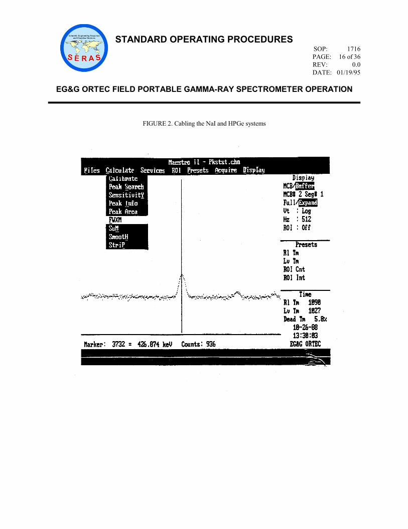
3. At main menu select MAESTRO. Hit enter. The MAESTRO Spectrum Display should now be
on the screen (Figure 3, Appendix A). To the right of the screen is the display parameters,
indicating the location of the spectrum (MCB or Buffer), location of channel marker (Vertical
(Vt) and Horizontal (Hz)), count time in seconds and presets, as well as current date and time.
Along the top of the spectrum display, seven menus are listed horizontally. Three to the right
(Presets, Acquire and Display) are MCB menu options. The left four are Buffer functions. Note
that the menus will only be an option depending on the location of the spectrum. Furthermore, if
a Buffer menu is selected while in MCB, the spectrum program will automatically switch to the
Buffer WITHOUT transferring the spectrum.

STANDARD OPERATING PROCEDURES
SOP: 1716
PAGE: 8 of 36
REV: 0.0
DATE: 01/19/95
EG&G ORTEC FIELD PORTABLE GAMMA-RAY SPECTROMETER OPERATION
4. Apply the bias to the detector.
a. Select the Services menu. By hitting <ALT> S you will also retrieve this menu.
b. Select 92X ControL. Hit enter. A menu will appear on the screen listing the
parameter set up for the system. It should read as follows:
Coarse Gain --> 10
Fine Gain ----> 0.5001
Shaping Time -> short
Det Bias -----> +2500V for HPGe or +900V for NaI
Auto PZ ------> Trigger
c. Change any of the parameters that do not appear as above, by toggling with the arrow
keys to highlight the desired function and press enter.
d. The detector bias is set using the potentiometer located at the right bottom corner of
the Nomad base. You should have already turned the potentiometer to the desired
voltage reading and thus that value should be indicated in this menu as the Det Bias.
See section 7.2.3 for the procedure.
e. Enable the bias by toggling down to the Det Bias line. Hit enter.
f. Select On from the next menu. Be sure the HPGe system has been properly cooled
with liquid nitrogen.
g. The red light labeled High Voltage On, located on the right side of the Nomad base
will turn on to indicate that bias has been put on the detector.
5. Auto PZ - Amplifier Pole Zeroed. The amplifier should be pole zeroed anytime the detector is
changed, the shaping time is changed or the power to the module is turned off.
a. Place near the detector, a radioactive source of sufficient activity to produce a
relatively high count rate. A 1μCi, Cs-137 source will be sufficient.
b. Toggle to the PZ trigger option and press enter. A message of "Auto PZ complete"
appearing at the bottom of the screen, will indicate when pole zeroing has been
completed. Hit the Esc key to exit out of this menu.
6. Display Parameters
a. Change the spectrum display to "full" by selecting the Display menu and toggling
down to Full/Expand. Hit enter. The displayed menu on the right side of the screen
will indicate a change in the parameter chosen. To the right of the Display prompt
should read Expand.
b. To move up and down the spectrum channels, use the appropriate right or left arrow
keys. To change the y-axis, use the up or down arrows or page up, page down keys.
The MAESTRO II computer software also has "hot keys" that enable rapid movement
up and down the spectrum (Figure 4, Appendix A).
c. Select the Presets menu to change the live time. Toggle down to Live time, and input
the number of seconds for analysis. Live time indicates actual sample analysis time,
taking into consideration the detector dead time.

STANDARD OPERATING PROCEDURES
SOP: 1716
PAGE: 9 of 36
REV: 0.0
DATE: 01/19/95
EG&G ORTEC FIELD PORTABLE GAMMA-RAY SPECTROMETER OPERATION
7.4 Spectrum Energy Calibration
1. Center the K-40 and Cs-137 source in front of the detector probe, placing the K-40 closest to
the detector. If necessary, apply a little tape to hold the Cs-137 check source button centered on
the K-40 container.
2. Select the Acquire menu. Select Clear to erase the previous spectrum on the current MCB.
3. Select the Acquire menu. Select StarT. As data is being collected, the spectrum will
continually update the acquisition on the monitor. The right hand side display menu, lower right
corner indicates the display time including the percent dead time.
4. Upon completion switch to the buffer by selecting the Acquire menu. Toggle down to
MCB>Buffer. Hit enter. When the spectrum has been transferred, the Display menu along the
right side of the screen will be updated and the "Buffer" position will be highlighted. You may
have to select one of the buffer menu choices (ex. File) to move the spectrum to the buffer. The
spectrum will then transfer to the buffer and you may perform work on the spectrum. If you do
not physically transfer the spectrum to the buffer and just select one of the buffer menu items,
the spectrum will not be transferred over.
5. Scan the spectrum with the right and left arrow keys. Locate two peaks from the calibration
standard spectrum. When using, K-40 and Cs-137, locate the 661.7 keV gamma from Cs-137
and the 1460.8 keV from K-40. It may be necessary to also toggle the up and down arrow keys
to increase or decrease the y-axis scale. To become proficient in locating the peaks, it may take
some practice to become familiar with their location.
6. Place a Region of Interest (ROI) to encompass each peak.
a. Move the cursor to the channel at the beginning of the first peak for the first calibration
point. Typically, three channels to include background before and after the peak are
included in the ROI.
b. Select the ROI menu. Toggle down to Begin. Hit enter. Move the cursor to the end
of the peak and select the ROI menu and toggle down to End. Hit enter. The points
encompassing the peak will be indicated by a shaded feature. Repeat this same
procedure to place a ROI around the second peak. Record both ROI ranges.
c. Place the cursor inside the first ROI shaded area. Select the Calculate menu. Toggle
down to Calibrate. Hit enter. The program will prompt an answer for the peak in
channel #. Enter the energy of the first peak. When using Cs-137, the peak energy is
661.7. Hit enter. Cursor to the next peak and repeat above procedure. When using
K-40, the second peak energy will be 1460.8. Hit enter. Enter the units as "keV" for
the next prompt. The system will now be calibrated. Generally speaking, the spectrum
is calibrated between the two energies used as calibration points. Therefore, an ideal
calibration standard is one that would encompass the energy of the isotope for
quantification in the samples.
7. Save the Spectrum
All spectrums should be saved before returning to the MCB. If you do not save before exiting
the buffer the information and all changes will be lost in transition.
a. Select the File menu. Toggle to the Save function. Hit enter. Respond to the prompt

STANDARD OPERATING PROCEDURES
SOP: 1716
PAGE: 10 of 36
REV: 0.0
DATE: 01/19/95
EG&G ORTEC FIELD PORTABLE GAMMA-RAY SPECTROMETER OPERATION
"Enter file mane to be SAVED". Eight letter/number maximum. Hit enter.
b. Respond to the next prompt "Enter the SAMPLE DESCRIPTION". Note that when
the spectrum is retrieved, this description will be displayed.
7.5 Background Analysis
Background analyses are typically performed prior to sample analysis and in the area of sample analysis to
best represent the background levels.
1. Remove all radioactive sources and samples from the vicinity of the detector during background
analysis. Start an acquisition.
a. Select the Acquire menu.
b. Select Clear to erase the previous spectrum on the current MCB.
c. Select Acquire. Select StarT. As data is being collected, the spectrum will continually
update the acquisition on the monitor. The right hand side display menu, lower right
corner indicates the display time including the percent dead time.
2. Transfer the spectrum to the buffer.
a. Select the Acquire menu.
b. Select MCB/Buffer.
3. Save the spectrum.
a. Select the File menu.
b. Select Save. Enter a relevant file name and description.
7.6 Reference Standard and Sample Analysis
Be sure to calibrate the spectrum prior to sample analysis. Without a calibrated spectrum the data
collected will be useless. Perform the reference standard analysis prior to analyzing a sample (unknown)
for determination of activity.
1. Place the sample (standard or unknown) in front of the detector probe.
a. Clear out the old spectrum. Begin the acquisition by selecting the Acquire menu.
Select StarT.
b. Upon completion transfer spectrum to the buffer by selecting the Acquire menu.
Select MCB>Buffer.
2. Create a ROI to encompass the gamma peak of interest from the reference standard or the
unknown. Record this region.
a. Move the cursor to channel of the beginning of the peak for the first calibration point.
Typically, three channels to include background are included in the peak.
b. Select the ROI menu. Toggle down to Begin. Hit enter. Move the cursor to the end

STANDARD OPERATING PROCEDURES
SOP: 1716
PAGE: 11 of 36
REV: 0.0
DATE: 01/19/95
EG&G ORTEC FIELD PORTABLE GAMMA-RAY SPECTROMETER OPERATION
of the peak and select the ROI menu and toggle down to End. Hit enter. The points
encompassing the peak will be indicated by a shaded feature. Record this ROI.
3. Save the spectrum.
a. Select the File menu.
b. Select Save. Enter a relevant file name and description.
4. Determine the net area in the peak after stripping background.
a. Move the cursor inside the peak ROI. Select the Calculate menu. Select StriP. Hit
enter. Select the current background file to strip off the current spectrum. Hit enter.
Enter "0" for time ratio as the strip multiplier.
b. Move the cursor inside the ROI. Select the Calculate menu. Select Net Area. The net
area under the peak will be indicated along the bottom portion of the computer screen.
Record this value as (Cr) for the reference standard or (Cs) for the sample.
5. Determine the sample mass.
a. Tare a field scale with an empty sample container on the balance. Obtain the mass of
the sample and record this value as (Ms).
6. Identifying Unknowns
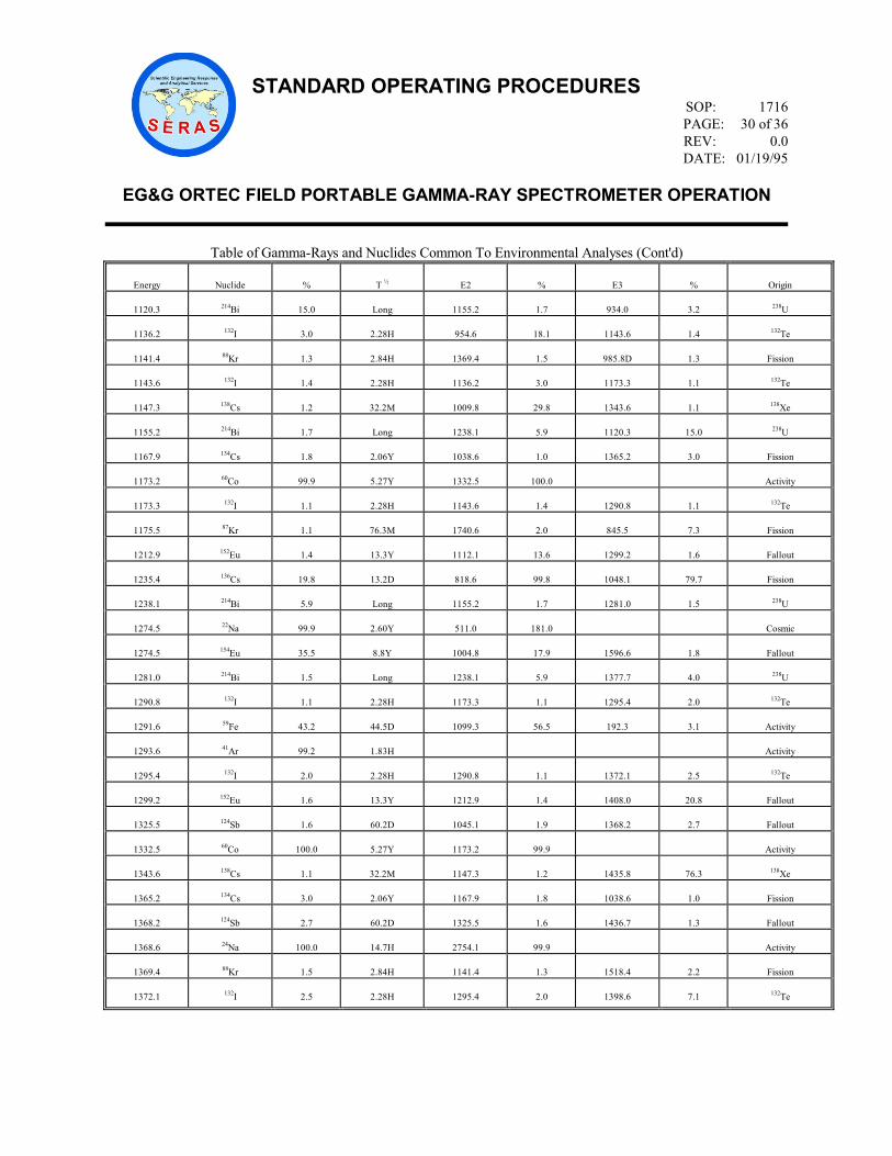
a. Refer to APPENDIX B, Table of Gamma-Ray Nuclides Common to Environmental
Analysis, to locate the energy of the unknown gamma peaks. Keep in mind the
limitations specified in section 4.0 of this SOP. Generally speaking, a proper
spectrum calibration should be insured before attempting to correctly identify
unknown radionuclides. In addition, knowledge of environmental radioactivity is often
recommended to assess the credibility of a find.
7.7 Detector Shutdown
Before removing power from the system, you must first remove the high voltage from the detector and
then quit out of the MAESTRO software. To do this:
1. Select the Services Menu. Toggle down to 92X ControL.
2. Toggle through next menu to Det Bias. Hit enter.
3. Select "Off" at next prompt.
4. Select the Services Menu. Toggle down to Quit. This will bring you to the MAESTRO Main
Menu. Toggle down to "Exit to System". Enter yes to the next prompt if the current file has
been saved.
5. Remove power from the Nomad base. Disconnect all cables.

STANDARD OPERATING PROCEDURES
SOP: 1716
PAGE: 12 of 36
REV: 0.0
DATE: 01/19/95
EG&G ORTEC FIELD PORTABLE GAMMA-RAY SPECTROMETER OPERATION
8.0 CALCULATIONS
8.1 Calculation of the Lower Limit of Detection (LLD)
It is often important to calculate the value below which, the instrument can not accurately detect. The
general calculation used to calculate the lower limit of detection is:
66.4BLLD 2/1
where:
LLD = Lower limit of detection
B = Background counts in ROI for gamma of interest
8.2 Determination of Sample Activity
The general formula for calculation of sample activity is:
sr
RnrrsS
MC
KMACA
where:
Mr= Reference Mass (g)
Ms= Sample Mass (g)
Cr= Reference Counts in Peak ROI after Strip
Cs= Sample Counts in Peak ROI after Strip
Ar= Activity of Reference Standard (pCi/g)
As= Activity of Sample (pCi/g)
KRn= Estimated Radon-222 Escape Factor for Radium quantification when using the Bi-210,
609 keV gamma peak to calculate for Radium
9.0 QUALITY ASSURANCE/QUALITY CONTROL (QA/QC)
There are no specific quality assurance activities which apply to the operation of the EG&G/ORTEC gamma
spectrometer. However, the following general QA procedures apply:
All instrumentation must be operated in accordance with operating instructions as supplied by the manufacturer,
unless otherwise specified in the work plan. Equipment checkouts and calibration activities must occur prior to
analysis operation and they must be documented. As a means of quality assurance, a health physicist or radiation
professional should be consulted prior to field work analyzing for radionuclides, who can thoroughly assess the
parameters on site and any interferences and check that proper calculations are being made with the data.
10.0 DATA VALIDATION
This section is not applicable to this SOP.

STANDARD OPERATING PROCEDURES
SOP: 1716
PAGE: 13 of 36
REV: 0.0
DATE: 01/19/95
EG&G ORTEC FIELD PORTABLE GAMMA-RAY SPECTROMETER OPERATION
11.0 HEALTH AND SAFETY
When handling hazardous materials, follow United States Environmental Protection Agency, Occupational Safety
and Health Administration, and corporate health and safety practices.
When handling radioactive samples, the exposures shall be kept as low as reasonably achievable. Refer to
ERT/SERAS SOP #3014, Radiation Protection Programs.
12.0 REFERENCES
EG&G ORTEC, Maestro II Software Operator's Manual, Version 1.4
EG&G ORTEC Solid-State Photon Detector Operators Manual - Gamma Gage
EG&G ORTEC Solid State Photon Detector Operators Manual - GEM Series
EG&G ORTEC Nomad Portable Spectroscopy System Model 92X-P Hardware Reference Manual
The Health Physics and Radiological Health Handbook, Nucleon Lectern Associates

STANDARD OPERATING PROCEDURES
SOP: 1716
PAGE: 14 of 36
REV: 0.0
DATE: 01/19/95
EG&G ORTEC FIELD PORTABLE GAMMA-RAY SPECTROMETER OPERATION
APPENDIX A
Figures
SOP #1716
January 1995

STANDARD OPERATING PROCEDURES
SOP: 1716
PAGE: 15 of 36
REV: 0.0
DATE: 01/19/95
EG&G ORTEC FIELD PORTABLE GAMMA-RAY SPECTROMETER OPERATION
FIGURE 1. Liquid Nitrogen Filling Diagram
STANDARD OPERATING PROCEDURES
SOP: 1716
PAGE: 16 of 36
REV: 0.0
DATE: 01/19/95
EG&G ORTEC FIELD PORTABLE GAMMA-RAY SPECTROMETER OPERATION
FIGURE 2. Cabling the NaI and HPGe systems

STANDARD OPERATING PROCEDURES
SOP: 1716
PAGE: 17 of 36
REV: 0.0
DATE: 01/19/95
EG&G ORTEC FIELD PORTABLE GAMMA-RAY SPECTROMETER OPERATION
FIGURE 3. MAESTRO Spectrum Display

STANDARD OPERATING PROCEDURES
SOP: 1716
PAGE: 18 of 36
REV: 0.0
DATE: 01/19/95
EG&G ORTEC FIELD PORTABLE GAMMA-RAY SPECTROMETER OPERATION
FIGURE 4. MAESTRO Hot Keys

STANDARD OPERATING PROCEDURES
SOP: 1716
PAGE: 19 of 36
REV: 0.0
DATE: 01/19/95
EG&G ORTEC FIELD PORTABLE GAMMA-RAY SPECTROMETER OPERATION
APPENDIX B
Table of Gamma-Ray Nuclides Common to Environmental Analysis
SOP #1716
January 1995

STANDARD OPERATING PROCEDURES
SOP: 1716
PAGE: 20 of 36
REV: 0.0
DATE: 01/19/95
EG&G ORTEC FIELD PORTABLE GAMMA-RAY SPECTROMETER OPERATION
Table of Gamma-Ray Nuclides Common To Environmental Analyses
Energy
Nuclide
%
T ½
E2
%
E6
%
Origin
14.4
57Co
9.5
272D
122.1
85.5
136.5
10.7
Activity
26.3
241Am
2.4
433Y
59.5
35.7
17.0LX
38.7
241Pu
30.0
140Ba
13.6
12.8D
162.7
6.2
304.9
4.3
Fallout
39.6
129I
7.5
1.6E7
30.0KX
70.8
Fission
39.9
212Bi
1.1
Long
727.3
6.7
1620.7
1.5
232Th
40.6
99Mo
1.1
65.9H
18.3X
3.2
140.5
3.5
Fallout
46.5
210Pb
4.1
22.3Y
238U
49.8
132Te
14.4
78.2H
30.0KX
70.9
111.9
1.9
Fallout
53.2
133Ba
2.2
10.5Y
81.0
34.2
31.0KX
101.3
Activity
59.5
237U
32.8
6.75D
101.1
26.0
208.0
22.0
Fallout
59.5
241Am
35.7
433Y
26.3
2.4
17.0LX
38.7
241Pu
60.0
155Eu
1.1
4.96Y
86.5
30.4
105.3
20.6
Fallout
61.5
239Np
1.0
2.36D
14.3LX
56.1
101.0KX
38.9
Fallout
63.3
234Th
3.8
Long
92.6D
5.4
238U
66.9
136Cs
12.5
13.2D
34.0KX
17.6
86.4
6.3
Fission
74.8X
214Pb
6.5
Long
77.1X
11.0
87.3X
3.9
238U
74.8X
212Pb
10.5
Long
77.1X
17.7
87.2
6.3
232Th
75.0X
208Tl
3.6
Long
72.8X
2.1
84.8X
1.3
232Th
77.1X
214Pb
11.0
Long
74.8X
6.5
87.2X
3.9
238U
77.1X
212Pb
17.7
Long
74.8X
10.5
87.2X
6.3
232Th
79.6
133Ba
3.2
10.5Y
53.2
2.2
Activity
80.1
144Ce
1.1
285D
133.5
11.1
696.5
1.3
Fallout
80.2
131I
2.6
8.04D
364.5
81.2
284.3
6.1
Fission
81.0
133Ba
34.2
10.5Y
276.4
7.3
79.6
3.2
Activity
81.0
133Xe
37.0
5.25D
79.6
0.2
31.0KX
40.1
Fission
84.3X
228Th
1.2
1.91Y
12.3X
3.1
232Th
D - Following half life indicates days M - Following half life indicates minutes
H - Following half life indicates hours X - Following energy indicates X-Ray
Y - Following half life indicates years D - Following energy indicates a doublet

STANDARD OPERATING PROCEDURES
SOP: 1716
PAGE: 21 of 36
REV: 0.0
DATE: 01/19/95
EG&G ORTEC FIELD PORTABLE GAMMA-RAY SPECTROMETER OPERATION
Table of Gamma-Rays and Nuclides Common To Environmental Analyses (cont'd)
Energy
Nuclide
%
T ½
E2
%
E3
%
Origin
86.4
136Cs
6.3
13.2D
66.9
12.5
153.3
7.5
Fission
86.5
155Eu
34.0
4.96Y
105.3
20.6
60.0
1.1
Fallout
87.2X
214Pb
3.9
Long
77.1X
11.0
241.9
7.5
238U
87.2X
212Pb
6.3
Long
238.6
43.6
77.1X
17.7
232Th
88.0
109Cd
3.6
463D
23.0KX
99.8
Activity
90.0X
228Ac
3.4
Long
93.4X
5.6
99.6
1.3
232Th
91.1
147Nd
28.0
11.0D
38.5KX
37.4
319.4
2.0
Fallout
92.6D
234Th
5.4
Long
63.3
3.8
238U
93.4X
228Ac
5.6
Long
90.0X
3.4
99.6
1.3
232Th
97.1
237U
16.0
6.75D
101.0
26.0
208.0
22.0
Fallout
99.6
228Ac
1.3
Long
129.0
2.9
209.4
4.1
232Th
101.1
237U
26.0
6.75D
59.5
32.8
208.0
22.0
Fallout
105.3
155Eu
20.6
4.96Y
86.5
34.0
60.0
1.1
Fallout
105.4X
228Ac
2.0
Long
99.6
1.3
129.0
2.9
232Th
106.1
239Np
22.7
2.36D
61.5
1.0
117.0KX
11.6
Fallout
109.2
235U
1.5
70E7Y
93.4KX
5.5
143.8
10.5
Natural
111.9
132Te
1.9
78.2H
49.8
14.4
116.4
1.9
Fallout
113.9
237U
25.0
6.75D
101.1
26.0
208.0
22.0
Fallout
116.3
132Te
1.9
78.2H
111.9
1.9
228.3
88.2
Fallout
121.8
152Eu
28.4
13.3Y
344.3
26.6
244.7
7.5
Fallout
122.1
57Co
85.5
273D
136.5
10.7
14.4
9.5
Activity
123.1
154Eu
40.5
8.8Y
248.0
6.6
591.8
4.8
Fallout
127.2
101Rh
73.0
3.3Y
198.0
70.8
325.2
13.4
Fallout
129.0
228Ac
2.9
Long
99.6
1.3
209.4
4.1
232Th

STANDARD OPERATING PROCEDURES
SOP: 1716
PAGE: 22 of 36
REV: 0.0
DATE: 01/19/95
EG&G ORTEC FIELD PORTABLE GAMMA-RAY SPECTROMETER OPERATION
Table of Gamma-Rays and Nuclides Common To Environmental Analyses (Cont'd)
Energy
Nuclide
%
T ½
E2
%
E3
%
Origin
133.5
144Ce
11.1
285D
696.5
1.3
80.1
1.1
Fallout
136.5
57Co
10.7
272D
122.1
85.5
14.4
9.5
Activity
138.0
138Cs
1.5
32.2M
227.7
1.5
462.8
30.7
138Xe
140.5
99Mo
3.5
65.9H
40.6
1.1
181.1
6.1
Fallout
140.5
99mTc
87.2
6.01H
18.4X
6.1
20.6X
1.2
99Mo
143.8
235U
10.5
70E7Y
109.2
1.5
163.4
4.7
Natural
145.4
141Ce
48.4
32.5D
37.0KX
17.4
Fission
151.2
85mKr
75.2
4.48H
304.9
13.7
Fission
153.3
136Cs
7.5
13.2D
86.4
6.3
164.0
4.6
Fission
153.9
138Xe
6.0
14.1M
242.7
3.5
258.4
31.5
Fission
162.7
140Ba
6.2
12.8D
304.9
4.3
30.0
13.6
Fallout
163.4
235U
4.7
70E7Y
143.8
10.5
185.7
53.0
Natural
164.0
136Cs
4.6
13.2D
153.3
7.5
176.6
13.6
Fission
165.9
139Ce
79.9
138D
34.0KX
79.5
Activity
166.0
88Kr
3.1
2.84H
196.3
26.0
362.3
2.3
Fission
176.3
125Sb
6.8
2.73Y
427.9
29.4
380.4
1.5
Fallout
176.6
136Cs
13.6
13.2D
164.0
4.6
273.7
12.7
Fission
181.1
99Mo
6.1
65.9H
140.5
3.5
366.4
1.2
Fallout
185.7
235U
53.0
70E7Y
143.8
10.5
205.3
4.7
Natural
186.1
226Ra
3.3
1600Y
Natural
192.3
59Fe
3.1
44.5D
1099.3
56.5
1291.6
43.2
Activity
196.3
88Kr
26.0
2.84H
362.3
2.3
166.0
3.1
Fission
198.0
101Rh
70.8
3.3Y
127.2
73.0
325.2
13.4
Fallout
205.3
235U
4.7
70E7Y
185.7
53.0
143.8
10.5
Natural
208.0
237U
22.0
6.75D
59.5
32.8
101.1
26.0
Fallout
209.4
228Ac
4.1
Long
129.0
2.9
270.3
3.8
232Th
227.7
138Cs
1.5
32.2M
138.0
1.5
409.0
4.7
138Xe
228.2
239Np
10.7
2.36D
106.1
22.7
277.6
14.2
Fallout

STANDARD OPERATING PROCEDURES
SOP: 1716
PAGE: 23 of 36
REV: 0.0
DATE: 01/19/95
EG&G ORTEC FIELD PORTABLE GAMMA-RAY SPECTROMETER OPERATION
Table of Gamma-Rays and Nuclides Common To Environmental Analyses (Cont'd)
Energy
Nuclide
%
T ½
E2
%
E3
%
Origin
228.3
132Te
88.2
78.2H
116.4
1.9
111.9
1.9
Fallout
233.2
133mXc
10.3
2.19D
30.0KX
56.3
Fission
238.6
212Pb
43.6
Long
300.0
3.3
232Th
240.8
224Ra
3.9
Long
232Th
241.9
214Pb
7.5
Long
295.1
19.2
352.0
37.1
238U
242.7
138Xe
3.5
14.1M
153.9
6.0
258.4
31.5
Fission
244.7
152Eu
7.5
13.3Y
121.8
28.4
344.3
26.6
Fallout
248.0
154Eu
6.6
8.8Y
123.1
40.5
591.8
4.8
Fallout
249.8
135Xe
90.0
9.10H
608.2
2.9
31.0KX
5.2
Fission
258.4
138Xe
31.5
14.1M
242.7
3.5
396.6
6.3
Fission
262.8
132I
1.4
2.28H
505.9
5.0
522.7
16.1
132Te
270.3
228Ac
3.8
Long
209.4
4.1
328.0
3.5
232Th
273.7
136Cs
12.7
13.2D
176.6
13.6
340.6
48.6
Fission
276.4
133Ba
7.1
10.5Y
302.9
18.4
81.0
34.2
Activity
277.3
208Tl
2.4
Long
510.6
7.8
583.0
30.9
232Th
277.6
238Np
14.2
2.36D
228.2
10.7
315.9
1.6
Fallout
279.2
203Hg
81.5
46.6D
74.6X
12.9
Fallout
284.3
131I
6.1
8.04D
364.5
81.2
80.2
2.6
Fission
295.1
214Pb
19.2
Long
351.9
37.1
241.9
7.5
238U
300.0
212Pb
3.3
Long
238.6
43.6
232Th
302.9
133Ba
18.4
10.5Y
276.4
7.1
356.0
62.2
Activity
304.9
140Ba
4.3
12.8D
162.7
6.2
423.7
3.1
Fallout
304.9
85mKr
13.7
4.48H
151.2
75.1
Fission
315.9
239Np
1.6
2.36D
277.6
14.2
334.3
2.1
Fallout
319.4
147Nd
2.0
11.0D
439.9
1.2
91.1
28.0
Fallout
320.1
51Cr
9.8
27.7D
Activity
325.2
101Rh
13.4
3.3Y
127.2
73.0
198.0
70.8
Fallout
328.0
228Ac
3.5
Long
270.3
3.8
338.4
12.4
232Th

STANDARD OPERATING PROCEDURES
SOP: 1716
PAGE: 24 of 36
REV: 0.0
DATE: 01/19/95
EG&G ORTEC FIELD PORTABLE GAMMA-RAY SPECTROMETER OPERATION
Table of Gamma-Rays and Nuclides Common To Environmental Analyses (Cont'd)
Energy
Nuclide
%
T ½
E2
%
E3
%
Origin
328.8
140La
20.7
40.3H
432.5
3.0
487.0
45.9
Fallout
334.3
239Np
2.1
2.36D
315.9
1.6
61.5
1.0
Fallout
338.4
228Ac
12.4
Long
328.0
3.5
409.6
2.2
232Th
340.6
136Cs
48.6
13.2D
273.7
12.7
818.6
99.8
Fission
344.3
152Eu
26.6
13.3Y
244.7
7.5
411.1
2.2
Fallout
352.0
214Pb
37.1
Long
241.9
7.5
295.1
19.2
238U
356.0
133Ba
62.2
10.5Y
302.9
18.4
383.8
8.9
Activity
362.3
88Kr
2.3
2.84H
196.3
26.0
834.9
13.0
Fission
364.5
131I
81.2
8.04D
637.0
7.3
284.3
6.1
Fission
366.4
99Mo
1.2
65.9H
181.1
6.1
739.5
12.1
Fallout
380.4
125Sb
1.5
2.73Y
176.3
6.8
427.9
29.4
Fallout
383.8
133Ba
8.9
10.5Y
356.0
62.2
302.9
18.4
Activity
396.6
138Xe
6.3
14.1M
258.4
31.5
401.5
2.2
Fission
401.5
138Xe
2.2
14.1M
434.6
20.3
396.6
6.3
Fission
402.6
87Kr
49.6
76.3M
845.5
7.3
673.9
1.9
Fission
409.0
138Cs
4.7
32.3M
227.7
1.5
462.8
30.7
138Xe
409.6
228Ac
2.2
Long
338.4
12.4
463.1
4.6
232Th
411.1
152Eu
2.2
13.3Y
344.3
26.6
444.0D
3.1
Fallout
415.3
102Rh
2.1
2.89Y
418.5
10.6
420.4
3.2
Fallout
418.5
102Rh
10.6
2.89Y
415.3
2.1
420.4
3.2
Fallout
420.4
102Rh
3.2
2.89Y
418.5
10.6
475.1
95.0
Fallout
423.7
140Ba
3.1
12.8D
437.6
1.9
304.9
4.3
Fallout
427.9
125Sb
29.4
2.73Y
380.4
1.5
463.4
10.5
Fallout
432.5
140La
3.0
40.3H
487.0
45.9
328.8
20.7
Fallout
434.6
138Xe
20.3
14.1M
401.5
2.2
1114.3
1.5
Fission
437.6
140Ba
1.9
12.8D
537.3
24.4
423.7
3.1
Fallout
439.9
147Nd
1.2
11.0D
319.4
2.0
531.0
13.1
Fallout
444.0D
152Eu
3.1
13.3Y
411.1
2.2
778.9
13.0
Fallout

STANDARD OPERATING PROCEDURES
SOP: 1716
PAGE: 25 of 36
REV: 0.0
DATE: 01/19/95
EG&G ORTEC FIELD PORTABLE GAMMA-RAY SPECTROMETER OPERATION
Table of Gamma-Rays and Nuclides Common To Environmental Analyses (Cont'd)
Energy
Nuclide
%
T ½
E2
%
E3
%
Origin
446.8
110mAg
3.8
250D
657.8
94.6
620.4
2.8
Activity
462.8
138Cs
30.7
32.2M
547.0
10.8
409.0
4.7
138Xe
463.1
228Ac
4.6
Long
409.6
2.2
755.3
1.3
232Th
463.4
125Sb
10.5
2.73X
427.9
29.4
600.5
17.8
Fallout
468.7
102mRh
2.9
207D
475.1
46.0
556.6
1.9
Fallout
475.1
102mRh
46.0
207D
468.7
2.9
556.6
1.9
Fallout
475.1
102Rh
95.0
2.89Y
628.1
8.5
420.5
3.2
Fallout
475.4
134Cs
1.5
2.06Y
563.2
8.4
569.3
15.4
Fission
477.6
7Be
10.3
53.2D
Cosmic
487.1
140La
45.5
40.2H
751.9
4.3
432.6
2.9
Fallout
497.1
103Ru
89.5
39.6D
610.3
5.6
Fallout
505.9
132I
5.0
2.28H
262.8
1.4
522.7
16.1
132Te
510.6
208T1
7.8
Long
277.3
2.4
583.0
30.9
232Th
511.0
65Zn
2.9
244D
1115.5
50.8
Activity
511.0
58Co
30.0
70.9D
810.8
99.5
Activity
511.0
22Na
180.8
2.60Y
1274.5
99.9
Cosmic
511.9
106Ru
20.7
372D
1050.4
1.5
621.9
9.8
Fallout
514.0
85Sr
99.3
64.8D
13.4KX
50.6
15.0KX
8.7
Activity
522.7
132I
16.1
2.28H
505.9
5.0
547.0
1.3
132Te
526.6
135mXe
81.2
15.7M
30.0KX
14.0
Fission
531.0
147Nd
13.1
11.0D
439.9
1.2
319.4
2.0
Fallout
537.3
140Ba
24.4
12.8D
437.6
1.9
423.7
3.1
Fallout
547.0
138Cs
10.8
32.2M
462.8
30.7
871.7
5.1
138Xe
547.0
132I
1.3
2.28H
522.7
16.1
621.2
~2.0
132Te
556.6
102mRh
1.9
207D
475.1
46.0
628.1
5.5
Fallout
563.2
134Cs
8.4
2.06Y
475.4
1.5
569.3
15.4
Fission
569.3
134Cs
15.4
2.06Y
563.2
8.4
604.7
97.6
Fission
569.2
207Bi
97.8
32.3Y
1063.1
74.9
1769.7
6.9
Fallout

STANDARD OPERATING PROCEDURES
SOP: 1716
PAGE: 26 of 36
REV: 0.0
DATE: 01/19/95
EG&G ORTEC FIELD PORTABLE GAMMA-RAY SPECTROMETER OPERATION
Table of Gamma-Rays and Nuclides Common To Environmental Analyses (Cont'd
Energy
Nuclide
%
T ½
E2
%
E3
%
Origin
583.0
208T1
30.9
Long
510.6
7.8
860.3
4.3
232Th
591.8
154Eu
4.8
8.8Y
248.0
6.6
692.5
1.7
Fallout
600.5
125Sb
17.8
2.73Y
463.4
10.5
606.6
5.0
Fallout
602.7
124Sb
97.8
60.2D
645.9
7.4
709.3
1.4
Fallout
604.7
134Cs
97.6
2.06Y
795.9
85.4
569.3
15.4
Fission
606.6
125Sb
5.0
2.73Y
600.5
17.8
635.9
11.3
Fallout
608.2
135Xe
2.9
9.10H
249.8
90.0
31.6KX
5.2
Fission
609.3
214Bi
46.1
Long
665.4
1.6
768.4
4.9
238U
610.3
103Ru
5.6
39.3D
497.1
88.7
Fallout
620.4
110mAg
2.8
250D
657.8
94.6
446.8
3.8
Activity
621.2
132I
~2.0
2.28H
547.1
1.3
630.3
13.8
132Te
621.9
106Ru
9.8
372D
511.9
20.7
1050.4
1.5
Fallout
628.1
102mRh
5.5
207D
556.6
1.9
1103.2
2.9
Fallout
628.1
102Rh
8.5
~2.9Y
475.1
95.0
631.3
56.0
Fallout
630.3
132I
13.8
2.28H
621.2
~2.0
650.6
2.7
132Te
631.3
102Rh
56.0
~2.9Y
628.1
8.5
692.4
1.8
Fallout
635.9
125Sb
11.3
2.73Y
606.6
5.0
671.4
1.8
Fallout
637.0
131I
7.3
8.04D
364.5
81.2
722.9
1.8
Fission
645.9
124Sb
7.4
60.2D
602.7
97.8
709.3
1.4
Fallout
650.6
132I
2.7
2.28H
630.3
13.8
667.7
98.7
132Te
657.8
110mAg
94.6
250D
620.4
2.8
677.6
10.4
Activity
661.7
137Cs
85.2
30.0Y
33.0KX
7.1
Fallout
665.4
214Bi
1.6
Long
609.3
46.1
768.4
4.9
238U
667.7
132I
98.7
2.28H
650.6
2.7
669.9
4.9
132Te
669.9
132I
4.9
2.28H
667.7
98.7
671.6
5.2
132Te
671.4
125Sb
1.8
2.73Y
635.9
11.3
606.6
5.0
Fallout
671.6
132I
5.2
2.28H
669.9
4.9
727.D
5.4
132Te
673.9
87Kr
1.9
76.3M
845.5
7.3
402.6
49.6
Fission
677.6
110mAg
10.4
250D
657.8
94.6
687.0
6.4
Activity

STANDARD OPERATING PROCEDURES
SOP: 1716
PAGE: 27 of 36
REV: 0.0
DATE: 01/19/95
EG&G ORTEC FIELD PORTABLE GAMMA-RAY SPECTROMETER OPERATION
Table of Gamma-Rays and Nuclides Common To Environmental Analyses (Cont'd)
Energy
Nuclide
%
T ½
E2
%
E3
%
Origin
687.0
110m
Ag
6.4
250D
677.6
10.4
706.7
16.4
Activity
692.4
102
Rh
1.8
~2.9Y
631.3
56.0
695.6
2.7
Fallout
692.5
154
Eu
1.7
8.8Y
591.8
4.8
723.4
19.7
Fallout
695.6
102
Rh
2.7
~2.9Y
692.4
1.8
697.6
45.7
Fallout
696.5
144
Ce
1.3
285D
133.5
11.1
80.1
1.1
Fallout
697.6
102Rh
45.7
~2.9Y
766.9
34.0
695.6
2.7
Fallout
706.7
110m
Ag
16.4
250D
687.0
6.4
744.3
4.7
Activity
709.3
124
Sb
1.4
60.2D
645.9
7.4
713.8
2.3
Fallout
713.8
124
Sb
2.3
60.2D
709.3
1.4
722.8
10.9
Fallout
722.8
124
Sb
10.9
60.2D
713.8
2.3
968.2
1.9
Fallout
722.9
131
I
1.8
8.04D
364.5
81.2
637.0
7.3
Fission
723.4
154
Eu
19.7
8.8Y
692.5
1.7
756.8
4.3
Fallout
724.2
95
Zr
44.1
64.0D
756.7
54.5
Fallout
727.0D
132
I
5.4
2.28H
671.6
5.2
728.7
1.1
132
Te
727.3
212
Bi
6.7
Long
39.9
1.1
1620.7
1.5
232
Th
728.7
132
I
1.1
2.28H
727.0D
5.4
772.7
76.2
132
Te
739.5
99
Mo
12.1
65.9H
366.4
1.2
777.9
4.4
Fallout
744.3
110m
Ag
4.7
250D
706.7
16.4
763.9
22.3
Activity
751.7
140
La
4.3
40.3H
487.0
45.9
815.8
23.6
Fallout
755.3
228
Ac
1.3
Long
463.1
4.6
772.3
1.1
232
Th
756.7
95
Zx
54.5
64.0D
724.2
44.1
Fallout
756.8
154
Eu
4.3
8.8Y
723.4
19.7
873.2
11.5
Fallout
763.1
208
T1
0.6
Long
583.0
30.9
860.3
4.3
232
Th
763.9
110m
Ag
22.3
250D
744.3
4.7
818.0
7.3
Activity
765.8
95
Nb
99.8
35.0D
Fallout
766.9
102
Rh
34.0
~2.9Y
697.6
45.7
1046.6
34.0
Fallout
768.4
214
Bi
5.0
Long
665.6
1.6
786.4D
0.3
238
U
772.3
228
Ac
1.1
Long
755.3
1.3
794.8
4.6
232
Th
772.7
132
I
76.2
2.28H
728.7
1.1
780.1
1.2
132
Te
777.9
99
Mo
4.4
65.9H
739.5
12.1
366.4
1.2
Fallout

STANDARD OPERATING PROCEDURES
SOP: 1716
PAGE: 28 of 36
REV: 0.0
DATE: 01/19/95
EG&G ORTEC FIELD PORTABLE GAMMA-RAY SPECTROMETER OPERATION
Table of Gamma-Rays and Nuclides Common To Environmental Analyses (Cont'd)
Energy
Nuclide
%
T ½
E2
%
E3
%
Origin
778.9
152
Eu
13.0
13.3Y
444.0D
3.1
867.4
4.2
Fallout
780.1
132
I
1.2
2.28H
772.7
76.2
809.8
2.9
132
Te
785.5
212
Bi
1.1
Long
727.3
6.7
1620.7
1.5
232
Th
794.8
228
Ac
4.6
Long
772.3
1.1
830.6
0.6
232
Th
786.4
214
Bi
0.3
Long
768.4
4.9
806.2
1.2
238
U
795.8
134
Cs
85.4
2.06Y
604.7
97.8
801.9
8.7
Fission
802.0
134
Cs
8.7
2.06Y
795.9
85.4
1038.6
1.0
Fission
806.2
214
Bi
1.2
Long
786.4
0.3
934.0
3.2
238
U
809.8
132
I
2.9
2.28H
780.1
1.2
812.3
5.6
132
Te
810.8
58
Co
99.5
70.9D
511.0
30.0
Activity
812.3
132
I
5.6
2.28H
809.8
2.9
877.2
1.1
132
Te
815.8
140
La
23.6
40.3H
751.7
4.3
867.8
5.6
Fallout
818.0
110m
Ag
7.3
250D
763.9
22.3
884.7
72.7
Activity
818.6
136
Cs
99.8
13.2D
340.6
48.6
1048.1
79.7
Fission
830.6
228
Ac
0.6
Long
794.8
4.6
835.6
1.7
232
Th
834.8
54
Mn
100.0
312.2D
Fallout
834.9
88
Kr
13.0
2.84H
362.3
2.3
985.8D
1.3
Fission
835.6
228
Ac
1.7
Long
830.6
0.6
840.4
0.9
232
Th
840.4
228
Ac
0.9
Long
835.6
1.7
904.3
0.9
232
Th
845.5
87
Kr
7.3
76.3M
673.9
1.9
1175.5
1.1
Fission
860.3
208
T1
4.3
Long
2614.4
35.8
583.0
30.9
232
Th
867.4
152
Eu
4.2
13.3Y
778.9
13.0
964.1
14.5
Fallout
867.8
140
La
5.6
40.3H
815.8
23.6
919.6
2.7
Fallout
871.7
138
Cs
5.1
32.2M
547.0
10.8
1009.8
29.8
138
Xe
873.2
154
Eu
11.5
8.8Y
756.8
4.3
996.3
10.3
Fallout
877.2
132
I
1.1
2.28H
812.3
5.6
954.6
18.1
132
Te
884.7
110m
Ag
72.7
250D
818.0
7.3
937.5
34.4
Activity
898.1
88
Y
92.7
107D
1836.1
99.4
Activity
898.0
88
Rb
14.1
17.8M
1836.1
21.4
2677.9
2.0
88
Kr
904.3
228
Ac
0.9
Long
840.4
0.9
911.2
29.0
232
Th

STANDARD OPERATING PROCEDURES
SOP: 1716
PAGE: 29 of 36
REV: 0.0
DATE: 01/19/95
EG&G ORTEC FIELD PORTABLE GAMMA-RAY SPECTROMETER OPERATION
Table of Gamma-Rays and Nuclices Common To Environmental Analyses (Cont'd)
Energy
Nuclide
%
T ½
E2
%
E3
%
Origin
911.2
228
Ac
29.0
Long
966.0D
23.2
840.4
0.9
232
Th
919.6
140
La
2.7
40.3H
867.8
5.6
925.2
7.0
Fallout
925.2
140
La
7.1
40.3H
487.0
45.9
919.6
2.7
Fallout
934.0
214
Bi
3.2
Long
1120.3
15.0
806.2
1.2
238
U
937.5
110m
Ag
34.4
250D
1384.3
24.3
884.7
72.7
Activity
954.6
132
I
18.1
2.28H
877.2
1.1
1136.2
3.0
132
Te
964.1
152
Eu
14.5
13.3Y
1085.9
9.9
867.4
4.2
Fallout
964.6
228
Ac
5.8
Long
969.0
17.4
911.2
29.0
232
Th
968.2
124
Sb
1.9
60.2D
1045.1
1.9
722.8
10.9
Fallout
969.0
228
Ac
17.4
Long
911.2
29.0
1459.2
1.1
232
Th
985.8
88
Kr
1.3
2.84H
1141.4
1.3
834.9
13.0
Fission
996.3
154
Eu
10.3
8.8Y
1004.8
17.9
873.2
11.5
Fallout
1001.0
234m
Pa
0.7
Long
766.4
0.2
742.8
0.1
238
U
1004.8
154
Eu
17.9
8.8Y
1274.5
35.5
996.3
10.3
Fallout
1009.8
138
Cs
29.8
32.2M
1147.3
1.2
871.7
5.1
138
Xe
1038.6
134
Cs
1.0
2.06Y
1167.9
1.8
802.0
8.7
Fission
1045.1
124
Sb
1.9
60.2D
1325.5
1.6
968.2
1.9
Fallout
1046.6
102
Rh
33.0
2.9Y
1103.2
4.4
766.9
34.0
Fallout
1048.1
136
Cs
79.7
13.2D
818.6
99.8
1235.4
19.8
Fission
1050.4
106
Ru
1.5
372D
511.9
20.7
621.9
9.8
Fallout
1063.1
207
Bi
74.9
32.2Y
569.2
97.8
1769.7
6.9
Fallout
1085.9
152
Eu
9.9
13.3Y
1112.1
13.6
964.1
14.5
Fallout
1099.3
59
Fe
56.5
44.5D
1291.6
43.2
192.3
3.1
Fallout
1103.2
102m
Rh
2.9
207D
556.6
1.9
628.1
5.5
Fallout
1103.2
102
Rh
4.4
2.9Y
1046.6
33.0
1112.9
18.9
Fallout
1112.1
152
Eu
13.6
13.3Y
1085.9
9.9
1212.9
1.4
Fallout
1112.9
102
Rh
18.9
2.9Y
1046.6
33.0
1103.2
4.4
Fallout
1114.3
138
Xe
1.5
14.1M
1768.4
16.7
434.6
20.3
Fission
1115.5
65
Zn
50.8
244D
511.0
2.9
Activity
STANDARD OPERATING PROCEDURES
SOP: 1716
PAGE: 30 of 36
REV: 0.0
DATE: 01/19/95
EG&G ORTEC FIELD PORTABLE GAMMA-RAY SPECTROMETER OPERATION
Table of Gamma-Rays and Nuclides Common To Environmental Analyses (Cont'd)
Energy
Nuclide
%
T ½
E2
%
E3
%
Origin
1120.3
214
Bi
15.0
Long
1155.2
1.7
934.0
3.2
238
U
1136.2
132
I
3.0
2.28H
954.6
18.1
1143.6
1.4
132
Te
1141.4
88
Kr
1.3
2.84H
1369.4
1.5
985.8D
1.3
Fission
1143.6
132
I
1.4
2.28H
1136.2
3.0
1173.3
1.1
132
Te
1147.3
138
Cs
1.2
32.2M
1009.8
29.8
1343.6
1.1
138
Xe
1155.2
214
Bi
1.7
Long
1238.1
5.9
1120.3
15.0
238
U
1167.9
134
Cs
1.8
2.06Y
1038.6
1.0
1365.2
3.0
Fission
1173.2
60
Co
99.9
5.27Y
1332.5
100.0
Activity
1173.3
132
I
1.1
2.28H
1143.6
1.4
1290.8
1.1
132
Te
1175.5
87
Kr
1.1
76.3M
1740.6
2.0
845.5
7.3
Fission
1212.9
152
Eu
1.4
13.3Y
1112.1
13.6
1299.2
1.6
Fallout
1235.4
136
Cs
19.8
13.2D
818.6
99.8
1048.1
79.7
Fission
1238.1
214
Bi
5.9
Long
1155.2
1.7
1281.0
1.5
238
U
1274.5
22
Na
99.9
2.60Y
511.0
181.0
Cosmic
1274.5
154
Eu
35.5
8.8Y
1004.8
17.9
1596.6
1.8
Fallout
1281.0
214
Bi
1.5
Long
1238.1
5.9
1377.7
4.0
238
U
1290.8
132
I
1.1
2.28H
1173.3
1.1
1295.4
2.0
132
Te
1291.6
59
Fe
43.2
44.5D
1099.3
56.5
192.3
3.1
Activity
1293.6
41
Ar
99.2
1.83H
Activity
1295.4
132
I
2.0
2.28H
1290.8
1.1
1372.1
2.5
132
Te
1299.2
152
Eu
1.6
13.3Y
1212.9
1.4
1408.0
20.8
Fallout
1325.5
124
Sb
1.6
60.2D
1045.1
1.9
1368.2
2.7
Fallout
1332.5
60
Co
100.0
5.27Y
1173.2
99.9
Activity
1343.6
138
Cs
1.1
32.2M
1147.3
1.2
1435.8
76.3
138
Xe
1365.2
134
Cs
3.0
2.06Y
1167.9
1.8
1038.6
1.0
Fission
1368.2
124
Sb
2.7
60.2D
1325.5
1.6
1436.7
1.3
Fallout
1368.6
24
Na
100.0
14.7H
2754.1
99.9
Activity
1369.4
88
Kr
1.5
2.84H
1141.4
1.3
1518.4
2.2
Fission
1372.1
132
I
2.5
2.28H
1295.4
2.0
1398.6
7.1
132
Te

STANDARD OPERATING PROCEDURES
SOP: 1716
PAGE: 31 of 36
REV: 0.0
DATE: 01/19/95
EG&G ORTEC FIELD PORTABLE GAMMA-RAY SPECTROMETER OPERATION
Table of Gamma-Rays and Nuclides Common To Environmental Analyses (Cont'd)
Energy
Nuclide
%
T ½
E2
%
E3
%
Origin
1377.7
214Bi
4.0
Long
1281.0
1.5
1401.5
1.4
238U
1384.3
110mAg
24.3
250D
1475.8
4.0
937.5
34.4
Activity
1398.6
132I
7.1
2.28H
1372.1
2.5
1442.5
1.4
132Te
1401.5
214Bi
1.4
Long
1377.7
4.0
1408.0
2.5
238U
1408.0
214Bi
2.5
Long
1401.5
1.4
1509.2
2.2
238U
1408.0
152Eu
20.8
13.3Y
1299.2
1.6
1212.9
1.4
Fallout
1435.8
138Cs
76.3
32.2M
1343.6
1.1
2218.0
15.2
138Xe
1436.6
124Sb
1.3
60.2D
1368.2
2.7
1691.0
47.1
Fallout
1442.5
132I
1.4
2.28H
1398.6
7.1
1921.1
1.2
132Te
1459.2
228Ac
1.1
Long
1499.0D
1.6
969.0
17.4
232Th
1460.8
40K
10.7
1.3E9
Natural
1475.8
110mAg
4.0
250D
1384.3
24.3
1505.0
13.0
Activity
1499.0D
228Ac
1.6
Long
1459.2
1.1
1588.2
3.6
232Th
1505.0
110mAg
13.0
250D
1475.8
4.0
1562.3
1.0
Activity
1509.2
214Bi
2.2
Long
1408.0
2.5
1661.3
1.2
238U
1518.4
88Kr
2.2
2.84H
1369.4
1.5
1529.8
10.9
Fission
1529.8
88Kr
10.9
2.84H
1518.4
2.2
2029.9
4.5
Fission
1588.2
228Ac
3.6
Long
1499.0D
1.6
1630.5
2.0
232Th
1596.5
140La
95.4
40.3H
487.0
45.9
2571.7
3.4
Fallout
1596.6
154Eu
1.7
8.8Y
1274.5
35.5
1004.8
17.9
Fallout
1620.7
212Bi
1.5
Long
727.3
6.7
785.5
1.1
232Th
1630.5
228Ac
2.0
Long
1588.2
3.6
1499.0D
1.6
232Th
1661.3
214Bi
1.2
Long
1509.2
2.2
1729.6
3.1
238U
1691.0
124Sb
47.1
60.2D
2090.9
5.5
1436.7
1.3
Fallout
1729.6
214Bi
3.1
Long
1764.5
15.9
1661.3
1.2
238U
1740.6
87Kr
2.0
76.3M
1175.5
1.1
2011.9
2.9
Fission
1764.5
214Bi
15.9
Long
1729.6
3.1
1847.4
2.1
238U
1768.4
138Xe
16.7
14.1M
1114.3
1.5
1850.9
1.4
Fission
1769.7
207Bi
6.9
32.2Y
1063.1
74.9
569.2
97.8
Fallout

STANDARD OPERATING PROCEDURES
SOP: 1716
PAGE: 32 of 36
REV: 0.0
DATE: 01/19/95
EG&G ORTEC FIELD PORTABLE GAMMA-RAY SPECTROMETER OPERATION
Table of Gamma-Rays and Nuclides Common To Environmental Analyses (Cont'd)
Energy
Nuclide
%
T ½
E2
%
E3
%
Origin
1836.1
88
Rb
21.4
17.8M
2677.9
2.0
898.1
14.1
88
Kr
1836.1
88
Y
99.4
107D
898.1
92.7
Other
1847.4
214
Bi
2.1
Long
1764.5
15.9
2118.5
1.2
238
U
1850.9
138
Xe
1.4
14.1M
1768.4
16.7
2004.8
5.4
Fission
1921.1
132
I
1.2
2.28H
1442.5
1.4
2002.4
1.1
132
Te
2002.4
132
I
1.1
2.28H
1921.1
1.2
1442.5
1.4
132
Te
2004.8
138
Xe
5.4
14.1M
1850.9
1.4
2015.9
12.3
Fission
2011.9
87
Kr
2.9
76.3M
1740.6
2.0
2556.0D
13.1
Fission
2015.9
138
Xe
12.3
14.1M
2004.8
5.4
2079.3
1.4
Fission
2029.9
88
Kr
4.5
2.84H
1529.8
10.9
2035.5
3.7
Fission
2035.5
88
Kr
3.7
2.84H
2029.9
4.5
2195.8
13.2
Fission
2079.3
138
Xe
1.4
14.1M
2015.9
12.3
2252.3
2.3
Fission
2090.9
124
Sb
5.5
60.2D
1436.6
1.3
1691.0
47.1
Fallout
2118.5
214
Bi
1.2
Long
1847.4
2.1
2204.1
5.0
238
U
2195.8
88
Kr
13.2
2.84H
2035.5
3.7
2231.8
3.4
Fission
2204.1
214
Bi
5.0
Long
2447.7
1.6
2118.5
1.2
238
U
2217.8
138
Cs
15.2
32.2M
1435.8
76.3
2639.4
7.6
138
Xe
2231.8
88
Kr
3.4
2.84H
2195.8
13.2
2392.1
34.6
Fission
2252.3
138
Xe
2.3
14.1M
2079.3
1.4
2015.9
12.3
Fission
2392.1
88
Kr
34.6
2.84H
2231.8
3.4
2195.8
13.2
Fission
2447.7
214
Bi
1.6
Long
2204.1
5.0
2118.5
1.2
238
U
2521.7
140
La
3.4
40.3H
1596.5
96.4
487.0
45.9
Fallout
2556D
87
Kr
13.1
76.3M
2011.9
2.9
1740.6
2.0
Fission
2614.4
208
T1
35.8
Long
860.3
4.3
583.0
30.9
232
Th
2639.4
138
Cs
7.6
32.2M
2217.8
15.2
1435.8
76.3
138
Xe
2677.9
88
Rb
2.0
17.8M
1836.1
21.4
898.1
14.1
88
Kr
2754.0
24
Na
99.9
14.7H
1368.6
100.0
Activity
6129.2
16
N
68.8
7.13S
7115.2
4.7
Other
7115.2
16
N
4.7
7.13S
6129.2
68.8
Other

STANDARD OPERATING PROCEDURES
SOP: 1716
PAGE: 33 of 36
REV: 0.0
DATE: 01/19/95
EG&G ORTEC FIELD PORTABLE GAMMA-RAY SPECTROMETER OPERATION
APPENDIX C
Troubleshooting Guide
SOP #1716
January 1995
Troubleshooting Guide
PROBLEM PROBABLE CAUSE ACTION
Message: No Duel Port ADCAM interface not plugged Check all connections
Memory into the computer or Nomad
base properly
Low or High energy side Incorrect Pole Adjustment See section 7.3.4
tailing and poor resolution
Wandering Peaks or multiple peaks Unstable electronics, bad cable or Check each electronic
observed with pulse height analyzer or connector component and cables
Detector loses liquid nitrogen Break in Dewar Repair
or warms up quickly
Poor gamma ray resolution Power line noise, RF pick up Eliminate ac power line noise by
isolation or filtration. If
operation in a high RF field
consider more shielding.
Related Documents


