Application Note 51281 (Revision NEW, 5/2006) Original Instructions EGCP-3 LS 8406-113 Revision K Explanation of Software Changes made for the EGCP-3 LS Control

Welcome message from author
This document is posted to help you gain knowledge. Please leave a comment to let me know what you think about it! Share it to your friends and learn new things together.
Transcript

Application Note 51281(Revision NEW, 5/2006)
Original Instructions
EGCP-3 LS 8406-113 Revision K
Explanation of Software Changes made for the EGCP-3 LS Control

General Precautions
Read this entire manual and all other publications pertaining to the work to be performed before installing, operating, or servicing this equipment.
Practice all plant and safety instructions and precautions.
Failure to follow instructions can cause personal injury and/or property damage.
Revisions
This publication may have been revised or updated since this copy was produced. To verify that you have the latest revision, check manual 26311 , Revision Status & Distribution Restrictions of Woodward Technical Publications, on the publications page of the Woodward website:
www.woodward.com/publications The latest version of most publications is available on the publications page. If your publication is not there, please contact your customer service representative to get the latest copy.
Proper Use
Any unauthorized modifications to or use of this equipment outside its specified mechanical, electrical, or other operating limits may cause personal injury and/or property damage, including damage to the equipment. Any such unauthorized modifications: (i) constitute "misuse" and/or "negligence" within the meaning of the product warranty thereby excluding warranty coverage for any resulting damage, and (ii) invalidate product certifications or listings.
Translated Publications
If the cover of this publication states "Translation of the Original Instructions" please note:
The original source of this publication may have been updated since this translation was made. Be sure to check manual 26311 , Revision Status & Distribution Restrictions of Woodward Technical Publications, to verify whether this translation is up to date. Out-of-date translations are marked with . Always compare with the original for technical specifications and for proper and safe installation and operation procedures.
Revisions—Changes in this publication since the last revision are indicated by a black line
alongside the text. Woodward reserves the right to update any portion of this publication at any time. Information provided by Woodward is believed to be correct and reliable. However, no responsibility is assumed by Woodward unless otherwise expressly undertaken.
Copyright © Woodward 2006 All Rights Reserved

Application Note 51281 EGCP-3 LS Software Change for 8406-113
Woodward 1
Warnings and Notices Important Definitions
This is the safety alert symbol. It is used to alert you to potential personal injury hazards. Obey all safety messages that follow this symbol to avoid possible injury or death.
DANGER—Indicates a hazardous situation which, if not avoided, will result in death or serious injury.
WARNING—Indicates a hazardous situation which, if not avoided, could result in death or serious injury.
CAUTION—Indicates a hazardous situation which, if not avoided, could result in minor or moderate injury.
NOTICE—Indicates a hazard that could result in property damage only (including damage to the control).
IMPORTANT—Designates an operating tip or maintenance suggestion.
Overspeed / Overtemperature /
Overpressure
The engine, turbine, or other type of prime mover should be equipped with an overspeed shutdown device to protect against runaway or damage to the prime mover with possible personal injury, loss of life, or property damage.
The overspeed shutdown device must be totally independent of the prime mover control system. An overtemperature or overpressure shutdown device may also be needed for safety, as appropriate.
Personal Protective Equipment
The products described in this publication may present risks that could lead to personal injury, loss of life, or property damage. Always wear the appropriate personal protective equipment (PPE) for the job at hand. Equipment that should be considered includes but is not limited to: Eye Protection Hearing Protection Hard Hat Gloves Safety Boots Respirator
Always read the proper Material Safety Data Sheet (MSDS) for any working fluid(s) and comply with recommended safety equipment.
Start-up
Be prepared to make an emergency shutdown when starting the engine, turbine, or other type of prime mover, to protect against runaway or overspeed with possible personal injury, loss of life, or property damage.
Automotive Applications
On- and off-highway Mobile Applications: Unless Woodward's control functions as the supervisory control, customer should install a system totally independent of the prime mover control system that monitors for supervisory control of engine (and takes appropriate action if supervisory control is lost) to protect against loss of engine control with possible personal injury, loss of life, or property damage.

EGCP-3 LS Software Change for 8406-113 Application Note 51281
2 Woodward
Battery Charging Device
To prevent damage to a control system that uses an alternator or battery-charging device, make sure the charging device is turned off before disconnecting the battery from the system.
Electrostatic Discharge Awareness
Electrostatic Precautions
Electronic controls contain static-sensitive parts. Observe the following precautions to prevent damage to these parts: Discharge body static before handling the control (with power to
the control turned off, contact a grounded surface and maintain contact while handling the control).
Avoid all plastic, vinyl, and Styrofoam (except antistatic versions) around printed circuit boards.
Do not touch the components or conductors on a printed circuit board with your hands or with conductive devices.
To prevent damage to electronic components caused by improper handling, read and observe the precautions in Woodward manual 82715, Guide for Handling and Protection of Electronic Controls, Printed Circuit Boards, and Modules.
Follow these precautions when working with or near the control. 1. Avoid the build-up of static electricity on your body by not wearing clothing
made of synthetic materials. Wear cotton or cotton-blend materials as much as possible because these do not store static electric charges as much as synthetics.
2. Do not remove the printed circuit board (PCB) from the control cabinet unless absolutely necessary. If you must remove the PCB from the control cabinet, follow these precautions:
Do not touch any part of the PCB except the edges. Do not touch the electrical conductors, the connectors, or the
components with conductive devices or with your hands. When replacing a PCB, keep the new PCB in the plastic antistatic
protective bag it comes in until you are ready to install it. Immediately after removing the old PCB from the control cabinet, place it in the antistatic protective bag.
Application Note 51281 EGCP-3 LS Software Change for 8406-113
Woodward 3
EGCP-3 LS Software Change Information for Control 8406-113
Introduction Woodward is releasing application software 5418-144J.SCP for upgrading existing EGCP-3 controls in the field. This application note describes the changes made in the software and the process to upgrade the software in the control.
The software can be used to upgrade these existing controls: 8406-113 B, C, D, E, F, G, H, or J can be upgraded. The new unit part number will be 8406-113 Rev K. This converts software 5418-144 A, B, C, D, E, F, G, or H to 5418-
144 J.
Description of Software Changes 1. Improved engine crank routine.
A few EGCP-3 installations were experiencing an issue where the EGCP-3 would give a very short crank time of less than one second for one of its crank attempts. This would occur randomly about once every 40 starts or so. A small delay of 200 milliseconds was added to the speed pickup sampling at start up to correct this issue.
2. Frequency Trim feature is now disabled in the Baseload mode.
For applications that were isolated from the utility and using a combination of baseload and isochronous units, the Frequency Trim function could cause the speed bias output to reach its limits.
3. Soft loading ramps when switching an LS control between Process
Slave mode following an MC process reference and the LS Baseload mode. When operating a system with 3 or more LS units and an MC unit, if one EGCP-3 was in Proc Slave following the master and then the other was switched to local baseload then back to Proc Slave, the unit would not ramp back to the MC reference but would jump immediately. .
4. The kW load status screen will display the text “At Reference”, instead of “- - -“ after switching from Process Slave to Baseload mode.
5. Increased the acceptance range for the Gen Rated kVAR setting.
A program configuration error might occur when entering values for a 0.7 PF generator.
6. Allow a cooldown time when the Start Sequencing setting was set to
Disabled. Previously, if the Start Sequencing setting were disabled, and the control unit did not have a magnetic pickup connected, the control would not use the cooldown timer on a stop.

EGCP-3 LS Software Change for 8406-113 Application Note 51281
4 Woodward
7. Added several new variables to the control Modbus® * list. These variables are information from the LON network.
a. Online Demand 30256 b. Online Demand Units 30257 c. Online Capacity 30258 d. Online Capacity Units 30259 e. Lon Next Start Unit 30260 f. Lon Next Stop Unit 30261 g. LON error message number 30262 h. LON error Flag 10198
*—Modbus is a trademark of Modicon, Inc. 8. The Gen Stable Timer and Bus Stable Timer’s minimum was lowered
from 1 second to 0.1 second. 9. The Bus-to-Bus synchronizing feature is blocked on a unit operating in
the Baseload mode. When the raise and lower discrete inputs were closed to change the Baseload reference, this would enable the bus-to-bus synchronizing feature, and the control would try to change the bus frequency instead of the Baseload reference.
10. Added a new setting to tune the ones place of the MW hours. Previously, the smallest change that could be made was in the hundreds place when resetting the MW hours.
11. The synchronizing speed bias range was increased from ±23% to ±46%. This request was made for people with soft busses, where the frequency may fluctuate.
12. When Start Sequencing was Disabled and the control did not have an MPU signal connected, the text “Error” would show on the System Display screen after the breaker opened.
13. Two new set points were added to clamp the speed bias range.
a. Analog Output Menu – Speed Bias Max Limit b. Analog Output Menu – Speed Bias Min Limit
Especially for Caterpillar ADEM controls, the Speed bias range for the PWM output should be limited to avoid a loss of signal error at the ADEM.
14. Improvements were made to the Speed and Voltage control when using
Raise/Lower Relay Contacts. a. Real Load Control Menu – Speed R/L Deadband % b. Reactive Load Control Menu - Volt R/L Deadband %
Two new set points were added. Previously, there was no deadband for the speed or voltage bias, so the control would always be trying to raise or lower and never stop. Now a deadband can be set where the control will not issue a raise or lower command as long as the bias is within this range.
15. Improvements were made to the synchronizer when using Raise/Lower
Relay Contacts. a. Previously the voltage matching would only correct the voltage until it
was just inside the window. Now the control will continue to match the voltage tighter to within 50% of the window.
b. The raise lower dynamics were improved.
Application Note 51281 EGCP-3 LS Software Change for 8406-113
Woodward 5
16. Added a new kW De-Rate Feature. a. Real Load Control Menu – Rated Load De-Rate %
This feature allows a unit to change its kW rating for the load sharing and start/stop sequencing functions. Used, for example, on dual-fuel applications.
17. For Modbus control, it is now possible to control the Auto, Test, Run inputs remotely as long as the physical Auto input is closed or a combination of Auto and Run. Previously, if the control had the physical Auto and Run inputs closed, the Remote commands were blocked.
18. The de-bounce time of the discrete inputs was added.
When changing between one mode and another with the Auto, Test, and Run inputs, there is now a 0.5 second time delay to switch between modes.
19. During operation if the voltage bias ever reached its limits, the voltage control mode will not switch to Manual. Previously, if the limits were reached, the control mode switched to Manual, and in some cases would remain in manual even if the voltage problem were corrected.
20. Improved the kW Load and Unload ramps when in isolated load sharing. The control now uses the load control gain and integral gain during the ramp functions.
21. Added a new setting to allow the user to clear the alarms without a password.
a. Calibration Menu - CLEAR ALARM NO PASSWORD Previously, at least an operator level password level was required to clear alarms. Now if this setting is set True, no password is required at the panel or over Modbus. In any case, the alarms will still remain in the alarm log.
22. Added a new setting for Voltage Gain when synchronizing. a. Synchronizer Menu – SYNC VOLTAGE GAIN
This setting is used to make the voltage matching function of the Synchronizer more or less responsive.
Compatibility with Existing Controls The new software, 5418-144 J, will operate with all existing EGCP-3 controls.
Download Instructions This section provides instructions for downloading the 5418144J.SCP software needed to upgrade the 8406-113.
Loading the Application software may change some or all of the Configuration set points. These set points should be saved to a File before upgrading the unit.
An unsafe condition could occur with improper use of these software tools. Only trained personnel should have access to these tools.
EGCP-3 LS Software Change for 8406-113 Application Note 51281
6 Woodward
Requirements 9-pin DB9 null modem cable. Woodward Watch Window Professional Software. This program is available
on the Woodward website at www.woodward.com) for a five-day trial. A license can be purchased for extended use.
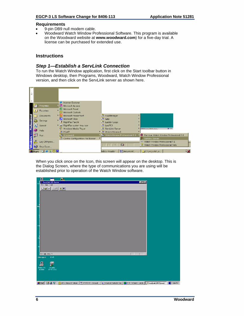
Instructions Step 1—Establish a ServLink Connection To run the Watch Window application, first click on the Start toolbar button in Windows desktop, then Programs, Woodward, Watch Window Professional version, and then click on the ServLink server as shown here.
When you click once on the Icon, this screen will appear on the desktop. This is the Dialog Screen, where the type of communications you are using will be established prior to operation of the Watch Window software.

Application Note 51281 EGCP-3 LS Software Change for 8406-113
Woodward 7
The first action to take inside the ServLink screen is to set up a new network definition file. Click once on File, and then on New as shown. The new network definition window will pop up on the computer screen.
This will open up the Network Options screen. This screen allows the user to configure the ServLink connection for serial com port, or modem. When a serial port is selected, the left side menus will be active and the right side menus will be grayed out.

EGCP-3 LS Software Change for 8406-113 Application Note 51281
8 Woodward
The “Use This Port” box of this screen is used to select which communication port (COM) or modem will be used to communicate using RS-232 protocol to the control. Clicking on the drop down box will tell the ServLink software to scan the computer and list any communications ports which are not being used by other applications, that may be used for serial communications. If the port that is desired does not appear, most likely it is being used by some other application on the computer. Another port should be selected, or the application that was using the port should be stopped. The next block down, “In this mode”, is used to select either multidrop or point-to-point communications over the serial port. Point-to-point communications assumes that the computer will be communicating with only one control at the other end of the network. Point-to-point communications should be used only when the communications between the computer and the control are made in a direct fashion, ( a null modem cable connected directly to the control). The advantage of using the point-to-point communications mode option is speed. Since the communications are only between the PC and one control, the ServLink software will scan for only one unit on the network. This takes less time than a multidrop communications mode, which scans for multiple controls on the network, regardless of how many units are actually connected to it. Use the multidrop communications option any time there are two or more controls that require monitoring from the computer on the same network. This will require an RS-422 or RS-485 network configuration. For RS-232 only point-to-point is allowed. When downloading a new software application, only one unit can be connected to the computer at a time. The next box down is the “At this baud rate” box. Different controls will operate at different baud rates. Please see the control manual to determine where the control baud rate is set. For example: EGCP-2 is 9600 (only) 2301D is 38400 (selectable) EGCP-3 is 115200 (selectable) The boxes on the right hand side of the ServLink New File setup screen are normally turned “off” when the “Use This Port” box is configured for the COM ports of the computer. These boxes are used when the Modem option is selected in the “Use This Port” box.
Application Note 51281 EGCP-3 LS Software Change for 8406-113
Woodward 9
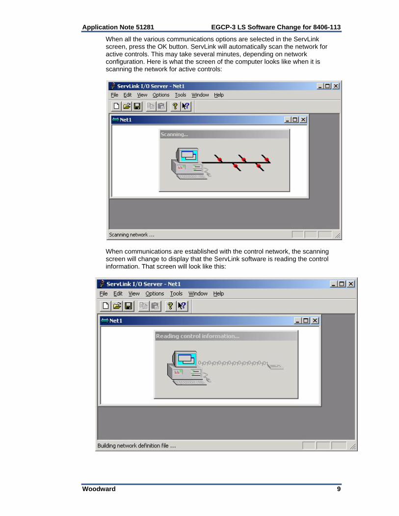
When all the various communications options are selected in the ServLink screen, press the OK button. ServLink will automatically scan the network for active controls. This may take several minutes, depending on network configuration. Here is what the screen of the computer looks like when it is scanning the network for active controls:
When communications are established with the control network, the scanning screen will change to display that the ServLink software is reading the control information. That screen will look like this:

EGCP-3 LS Software Change for 8406-113 Application Note 51281
10 Woodward
Once communications are established, and the data is read from the control network, the ServLink software will show each control it is communicating on the network by that control’s network address. Here is a typical ServLink network definition screen for an EGCP-3.
If your network configuration is constant (neither the number of controls on the network nor the PC attached to the network will change), you may want to save the Network Definition File you have created for ServLink. To do this, click on the File button in the upper left hand window of ServLink. Select “Save As”. A dialog window will pop up and ask you to name the new network definition file you have created. Typically, this file will be stored in the directory on the hard drive of the computer ServLink is operating from. The file name given to the network definition file will be given a “.net” extension. Once you have selected a file name, click on the OK button in the dialog box. This saves the network definition file you created. Once you have created and saved the network definition file for ServLink, all you have to do in the future to run the definition file is open ServLink from the Programs Menu, and select File, and then Open. When Open is selected, a list will appear containing the network definition file you created. Select the desired network definition file, and ServLink will automatically select the necessary communications options defined by the file and establish a communications link with the EGCP-2 control network. Now that ServLink has established a network connection, you may want to “minimize” the ServLink window by clicking on the Minimize button in the upper right hand of the ServLink Window. When you minimize an application, the software continues running, but the window is reduced to a button on the desktop toolbar. You can restore the application window to full size at any time by clicking on the reduced toolbar button for that software with the left mouse button.
Terminating ServLink will result in loss of communications with the network. The ServLink Network Definition file will have to be executed again to re-establish this link.

Application Note 51281 EGCP-3 LS Software Change for 8406-113
Woodward 11
Step 2—Start the Watch Window Software The Watch Window software adds the ability to monitor data from a computer. It also allows a user to save the control set points to a Tab delimited text file. The text file can then be printed, edited, and transferred into another control. The Watch Window Software will not run unless the computer is communicating with at least one control. Once the ServLink Communication has been established, start the Watch Window program from the Windows toolbar Start button.
The Watch Window Professional software is comprised of three separate windows, each with a different function.
1
2 3
EGCP-3 LS Software Change for 8406-113 Application Note 51281
12 Woodward
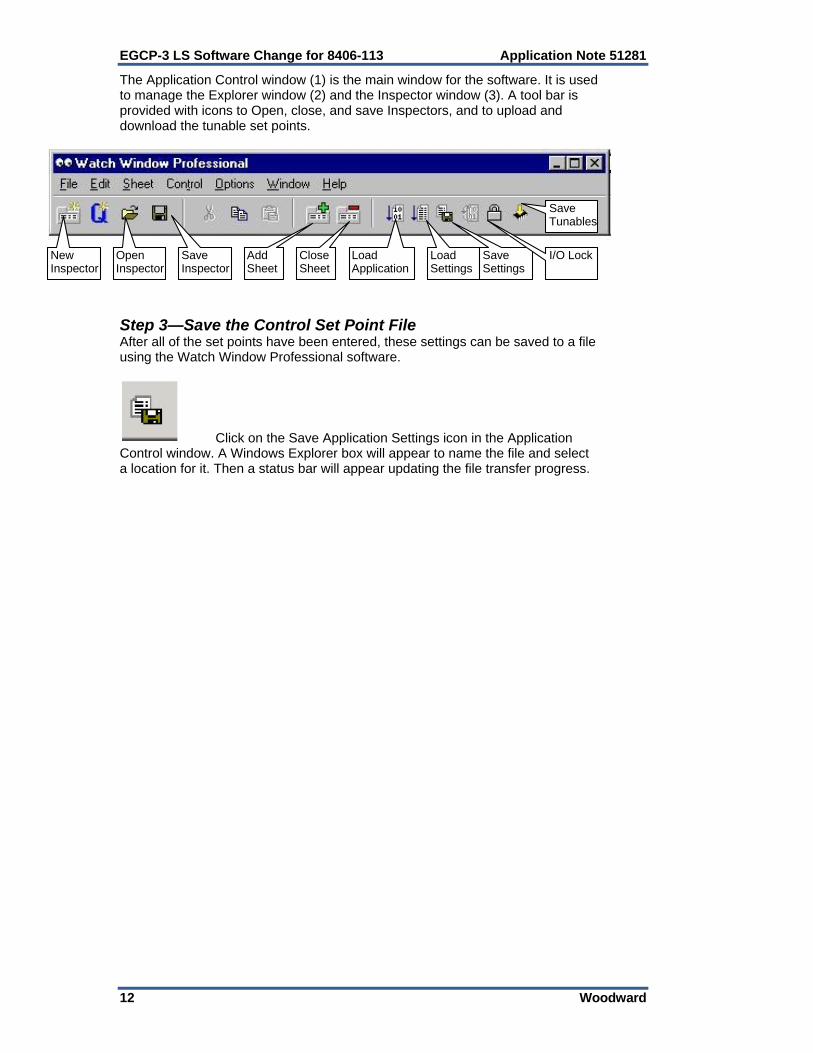
The Application Control window (1) is the main window for the software. It is used to manage the Explorer window (2) and the Inspector window (3). A tool bar is provided with icons to Open, close, and save Inspectors, and to upload and download the tunable set points.
New Inspector
Open Inspector
Save Inspector
Add Sheet
Close Sheet
Load Settings
Save Settings
I/O Lock Load Application
Save Tunables
Step 3—Save the Control Set Point File After all of the set points have been entered, these settings can be saved to a file using the Watch Window Professional software.
Click on the Save Application Settings icon in the Application Control window. A Windows Explorer box will appear to name the file and select a location for it. Then a status bar will appear updating the file transfer progress.

Application Note 51281 EGCP-3 LS Software Change for 8406-113
Woodward 13
The format of this file is tab de-limited. Using a program like Microsoft Excel, this set point file can be sorted and edited. Two columns will be formed, one with the variable name and the other with the variable value.
EGCP-3 LS Software Change for 8406-113 Application Note 51281
14 Woodward
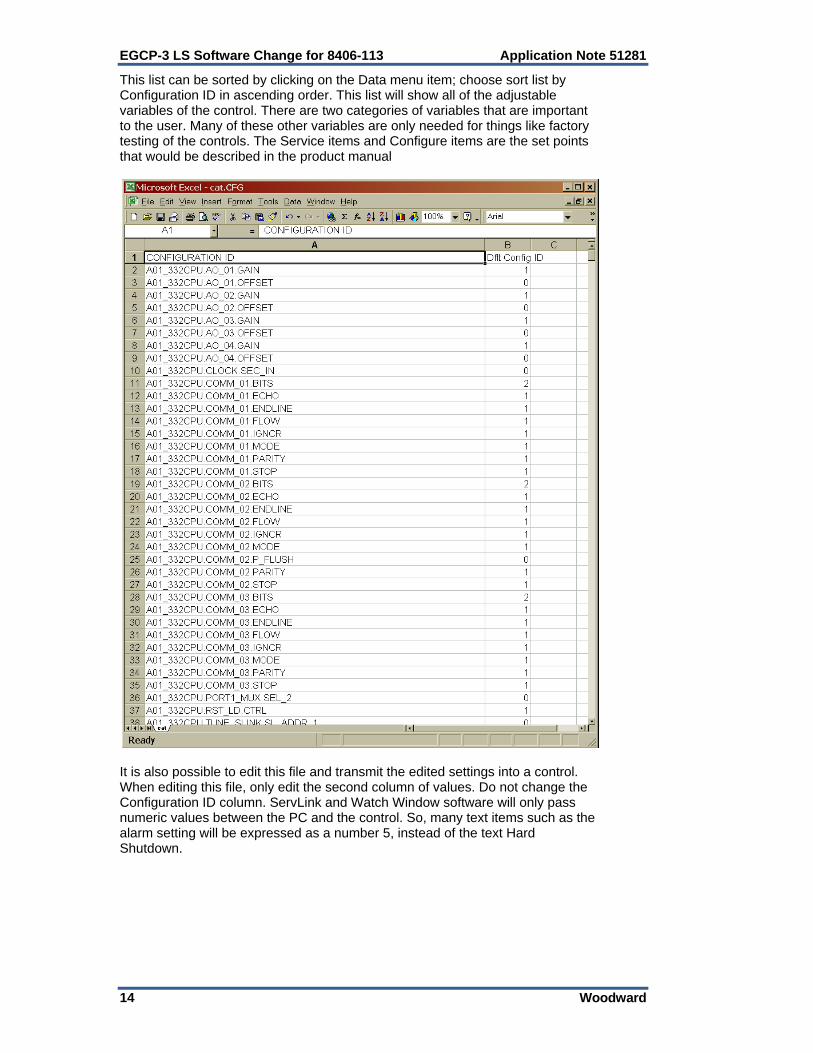
This list can be sorted by clicking on the Data menu item; choose sort list by Configuration ID in ascending order. This list will show all of the adjustable variables of the control. There are two categories of variables that are important to the user. Many of these other variables are only needed for things like factory testing of the controls. The Service items and Configure items are the set points that would be described in the product manual
It is also possible to edit this file and transmit the edited settings into a control. When editing this file, only edit the second column of values. Do not change the Configuration ID column. ServLink and Watch Window software will only pass numeric values between the PC and the control. So, many text items such as the alarm setting will be expressed as a number 5, instead of the text Hard Shutdown.
Application Note 51281 EGCP-3 LS Software Change for 8406-113
Woodward 15
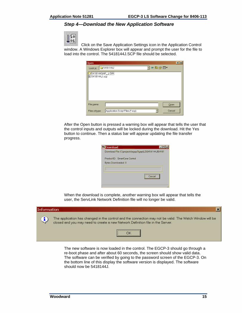
Step 4—Download the New Application Software
Click on the Save Application Settings icon in the Application Control window. A Windows Explorer box will appear and prompt the user for the file to load into the control. The 5418144J.SCP file should be selected.
After the Open button is pressed a warning box will appear that tells the user that the control inputs and outputs will be locked during the download. Hit the Yes button to continue. Then a status bar will appear updating the file transfer progress.
When the download is complete, another warning box will appear that tells the user, the ServLink Network Definition file will no longer be valid.
The new software is now loaded in the control. The EGCP-3 should go through a re-boot phase and after about 60 seconds, the screen should show valid data. The software can be verified by going to the password screen of the EGCP-3. On the bottom line of this display the software version is displayed. The software should now be 5418144J.

EGCP-3 LS Software Change for 8406-113 Application Note 51281
16 Woodward
Step 5—Build a New Network Definition file with ServLink The next step is to close both the Watch Window Professional application and the ServLink application. Then re-open the ServLink application and repeat the process of building a Network Definition file that was described earlier in the Step 1 Establish a ServLink Connection section. This section of the procedure should be repeated. After this new file has been loaded from the EGCP-3, this file can be saved. Step 6—Download the Previously Saved Application Settings
To load a set point file into a control, click on the Load Application Settings icon in the Application Control window. A warning box will appear that tells the user that the control inputs and outputs will be locked during the download. Hit the Yes button to go on. Next a Windows Explorer box will appear to find the set point file that is to be transferred.
Then a status bar will appear updating the file transfer progress. When the transfer is complete click on the Yes button to reset the control. Set point files can only be transferred when the unit is shut down. After the transfer is complete, verify that the correct values have been entered into the control. The unit should now be ready for operation.
Application Note 51281 EGCP-3 LS Software Change for 8406-113
Woodward 17
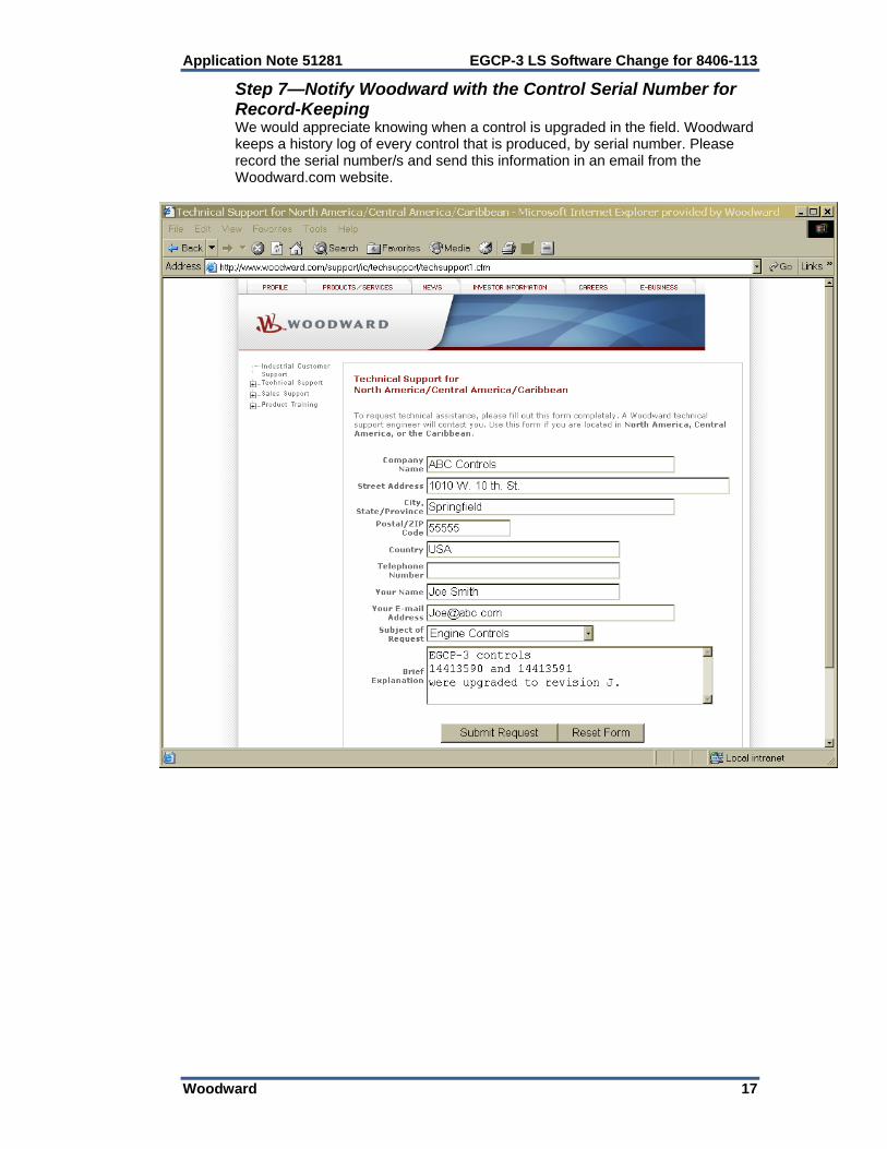
Step 7—Notify Woodward with the Control Serial Number for Record-Keeping We would appreciate knowing when a control is upgraded in the field. Woodward keeps a history log of every control that is produced, by serial number. Please record the serial number/s and send this information in an email from the Woodward.com website.

We appreciate your comments about the content of our publications.
Send comments to: [email protected]
Please reference publication 51281.
PO Box 1519, Fort Collins CO 80522-1519, USA 1000 East Drake Road, Fort Collins CO 80525, USA Phone +1 (970) 482-5811 Fax +1 (970) 498-3058
Email and Website—www.woodward.com
Woodward has company-owned plants, subsidiaries, and branches, as well as authorized distributors and other authorized service and sales facilities throughout the world.
Complete address / phone / fax / email information for all locations is available on our website.
Related Documents