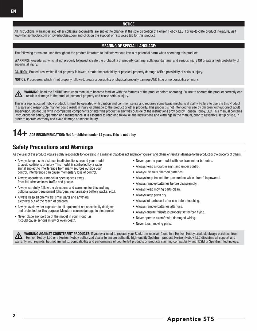
Instruction Manual Bedienungsanleitung Manuel d’utilisation Manuale di Istruzioni SAFE ® Select Technology, Optional Flight Envelope Protection

Welcome message from author
This document is posted to help you gain knowledge. Please leave a comment to let me know what you think about it! Share it to your friends and learn new things together.
Transcript
Instruction ManualBedienungsanleitungManuel d’utilisationManuale di Istruzioni
SAFE® Select Technology, Optional Flight Envelope Protection
EN
Apprentice STS2
Safety Precautions and Warnings
AGE RECOMMENDATION: Not for children under 14 years. This is not a toy.
As the user of this product, you are solely responsible for operating in a manner that does not endanger yourself and others or result in damage to the product or the property of others.
• Always keep a safe distance in all directions around your model to avoid collisions or injury. This model is controlled by a radio signal subject to interference from many sources outside your control. Interference can cause momentary loss of control.
• Always operate your model in open spaces away from full-size vehicles, traffic and people.
• Always carefully follow the directions and warnings for this and any optional support equipment (chargers, rechargeable battery packs, etc.).
• Always keep all chemicals, small parts and anything electrical out of the reach of children.
• Always avoid water exposure to all equipment not specifically designed and protected for this purpose. Moisture causes damage to electronics.
• Never place any portion of the model in your mouth as it could cause serious injury or even death.
• Never operate your model with low transmitter batteries.
• Always keep aircraft in sight and under control.
• Always use fully charged batteries.
• Always keep transmitter powered on while aircraft is powered.
• Always remove batteries before disassembly.
• Always keep moving parts clean.
• Always keep parts dry.
• Always let parts cool after use before touching.
• Always remove batteries after use.
• Always ensure failsafe is properly set before flying.
• Never operate aircraft with damaged wiring.
• Never touch moving parts.
NOTICE
All instructions, warranties and other collateral documents are subject to change at the sole discretion of Horizon Hobby, LLC. For up-to-date product literature, visit www.horizonhobby.com or towerhobbies.com and click on the support or resources tab for this product.
MEANING OF SPECIAL LANGUAGE:
The following terms are used throughout the product literature to indicate various levels of potential harm when operating this product:
WARNING: Procedures, which if not properly followed, create the probability of property damage, collateral damage, and serious injury OR create a high probability of superficial injury.
CAUTION: Procedures, which if not properly followed, create the probability of physical property damage AND a possibility of serious injury.
NOTICE: Procedures, which if not properly followed, create a possibility of physical property damage AND little or no possibility of injury.
WARNING: Read the ENTIRE instruction manual to become familiar with the features of the product before operating. Failure to operate the product correctly can result in damage to the product, personal property and cause serious injury.
This is a sophisticated hobby product. It must be operated with caution and common sense and requires some basic mechanical ability. Failure to operate this Product in a safe and responsible manner could result in injury or damage to the product or other property. This product is not intended for use by children without direct adult supervision. Do not use with incompatible components or alter this product in any way outside of the instructions provided by Horizon Hobby, LLC. This manual contains instructions for safety, operation and maintenance. It is essential to read and follow all the instructions and warnings in the manual, prior to assembly, setup or use, in order to operate correctly and avoid damage or serious injury.
14+
WARNING AGAINST COUNTERFEIT PRODUCTS: If you ever need to replace your Spektrum receiver found in a Horizon Hobby product, always purchase from Horizon Hobby, LLC or a Horizon Hobby authorized dealer to ensure authentic high-quality Spektrum product. Horizon Hobby, LLC disclaims all support and
warranty with regards, but not limited to, compatibility and performance of counterfeit products or products claiming compatibility with DSM or Spektrum technology.
EN
3
Table of ContentsSpecifications
If you own this product, you may be required to register with the FAA. For up-to-date information on how to register with the FAA, please visit https://registermyuas.faa.gov/. For additional assistance on regulations and guidance on UAS usage, visit knowbeforeyoufly.org/.
From the box to the air (No LAS or GPS Module) .....................................................4Charger Warnings ..................................................................................................4Charge the Flight Battery .......................................................................................5Transmitter (RTF) ...................................................................................................6Transmitter Setup (BNF) .........................................................................................7Dual Rates .............................................................................................................7Assemble the Aircraft .............................................................................................8Transmitter and Receiver Binding .........................................................................10Flight Battery Installation, SAFE system and Electronic Speed Control (ESC) Arming ..........................................................11Center of Gravity (CG) ..........................................................................................11Control Direction Test ...........................................................................................12Choose a Flying Field ...........................................................................................12Range Test ...........................................................................................................13Install the Propeller ..............................................................................................14Flying ..................................................................................................................15Landing ...............................................................................................................20Water Takeoff and Landing Using the Optional Float Set .......................................20Post Flight............................................................................................................20Factory settings for the Control Horns and Servo Arms .........................................21AS3X® System Trouble Shooting Guide (without GPS) ...........................................22Troubleshooting Guide (without GPS) ....................................................................22Optional Landing Assist Sensor (LAS) Upgrade .....................................................23Optional SAFE+ GPS Upgrade ..............................................................................24LED Indications ....................................................................................................32Service and Repairs .............................................................................................33Replacement Parts ...............................................................................................34AMA National Model Aircraft Safety Code .............................................................34Recommended Parts ............................................................................................34Optional Parts ......................................................................................................34Limited Warranty .................................................................................................35Warranty and Service Contact Information ...........................................................35FCC Information ...................................................................................................36IC Information ......................................................................................................36Compliance Information for the European Union ...................................................36
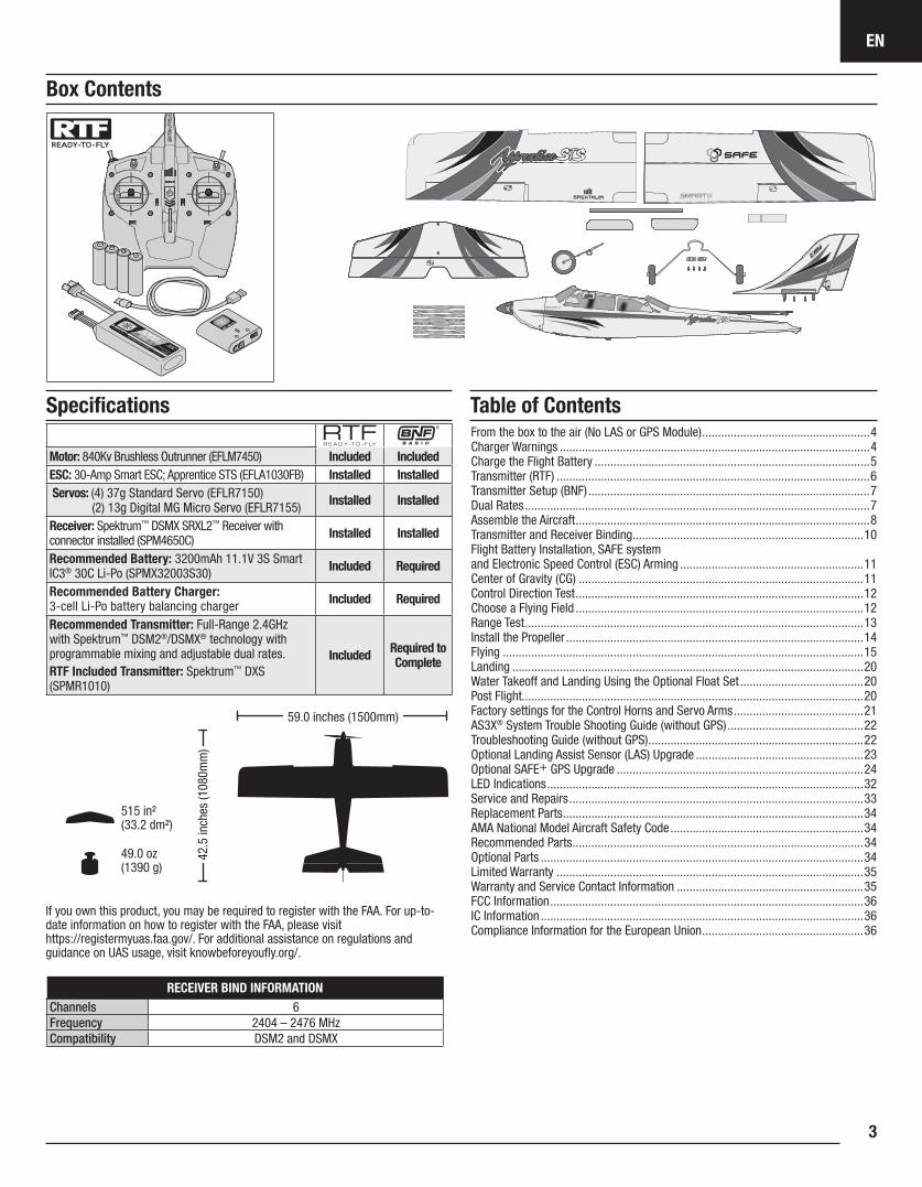
Box Contents
Motor: 840Kv Brushless Outrunner (EFLM7450) Included IncludedESC: 30-Amp Smart ESC; Apprentice STS (EFLA1030FB) Installed InstalledServos: (4) 37g Standard Servo (EFLR7150)
(2) 13g Digital MG Micro Servo (EFLR7155) Installed Installed
Receiver: Spektrum™ DSMX SRXL2™ Receiver with connector installed (SPM4650C) Installed Installed
Recommended Battery: 3200mAh 11.1V 3S Smart IC3® 30C Li-Po (SPMX32003S30) Included Required
Recommended Battery Charger: 3-cell Li-Po battery balancing charger Included Required
Recommended Transmitter: Full-Range 2.4GHz with Spektrum™ DSM2®/DSMX® technology with programmable mixing and adjustable dual rates.RTF Included Transmitter: Spektrum™ DXS (SPMR1010)
Included Required toComplete
49.0 oz (1390 g)
42.5
inch
es (1
080m
m)
59.0 inches (1500mm)
515 in² (33.2 dm²)
RECEIVER BIND INFORMATIONChannels 6Frequency 2404 – 2476 MHzCompatibility DSM2 and DSMX
EN
Apprentice STS4
CAUTION: All instructions and warnings must be followed exactly. Mishandling of Li-Po batteries can result in a fire, personal injury, and/or property damage.
• NEVER LEAVE CHARGING BATTERIES UNATTENDED.
• NEVER CHARGE BATTERIES OVERNIGHT.
• By handling, charging or using the included Li-Po battery, you assume all risks associated with lithium batteries.
• If at any time the battery begins to balloon or swell, discontinue use immediately. If charging or discharging, discontinue and disconnect. Continuing to use, charge or discharge a battery that is ballooning or swelling can result in fire.
• Always store the battery at room temperature in a dry area for best results.
• Always transport or temporarily store the battery in a temperature range of 40–120º F (5–49º C). Do not store battery or aircraft in a car or direct sunlight. If stored in a hot car, the battery can be damaged or even catch fire.
• Always charge batteries away from flammable materials.
• Always inspect the battery before charging and never charge dead or damaged batteries.
• Always disconnect the battery after charging, and let the charger cool between charges.
• Always constantly monitor the temperature of the battery pack while charging.
• ONLY USE A CHARGER SPECIFICALLY DESIGNED TO CHARGE LI-PO BATTERIES. Failure to charge the battery with a compatible charger may cause fire resulting in personal injury and/or property damage.
• Never discharge Li-Po cells to below 3V under load.
• Never cover warning labels with hook and loop strips.
• Never charge batteries outside recommended levels.
• Never attempt to dismantle or alter the charger.
• Never allow minors under the age of 14 to charge battery packs.
• Never charge batteries in extremely hot or cold places (recommended between 40–120° F or 5–49° C) or place in direct sunlight.
Charger Warnings
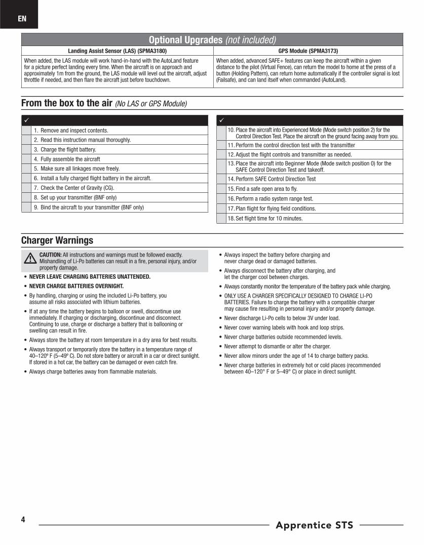
From the box to the air (No LAS or GPS Module)
1. Remove and inspect contents.
2. Read this instruction manual thoroughly.
3. Charge the flight battery.
4. Fully assemble the aircraft
5. Make sure all linkages move freely.
6. Install a fully charged flight battery in the aircraft.
7. Check the Center of Gravity (CG).
8. Set up your transmitter (BNF only)
9. Bind the aircraft to your transmitter (BNF only)
10. Place the aircraft into Experienced Mode (Mode switch position 2) for the
Control Direction Test. Place the aircraft on the ground facing away from you.
11. Perform the control direction test with the transmitter
12. Adjust the flight controls and transmitter as needed.
13. Place the aircraft into Beginner Mode (Mode switch position 0) for the SAFE Control Direction Test and takeoff.
14. Perform SAFE Control Direction Test
15. Find a safe open area to fly.
16. Perform a radio system range test.
17. Plan flight for flying field conditions.
18. Set flight time for 10 minutes.
Optional Upgrades (not included)Landing Assist Sensor (LAS) (SPMA3180) GPS Module (SPMA3173)
When added, the LAS module will work hand-in-hand with the AutoLand feature for a picture perfect landing every time. When the aircraft is on approach and approximately 1m from the ground, the LAS module will level out the aircraft, adjust throttle if needed, and then flare the aircraft just before touchdown.
When added, advanced SAFE+ features can keep the aircraft within a given distance to the pilot (Virtual Fence), can return the model to home at the press of a button (Holding Pattern), can return home automatically if the controller signal is lost (Failsafe), and can land itself when commanded (AutoLand).
EN
5
A
B
A
BA
B
The recommended battery for the E-flite Apprentice STS aircraft, included with the RTF version, is an 11.1V, 3200mAh 3S 30C Smart Technology LiPo battery with an IC3™ connector (SPMX32003S30). If using a different battery, the battery should be of similar capacity, dimensions and weight to fit in the fuselage. The aircraft electronic speed control is equipped with an IC3 device connector. Ensure the battery chosen is compatible. Always ensure the model balances at the recommended center of gravity (CG) with the chosen battery. Follow your chosen battery and battery charger instructions to charge the flight battery.
RTF Smart Technology Battery and S120 Charger, Specifications and OperationThe Spektrum S120 SMART Technology battery charger included with the RTF version of the aircraft is compatible only with Spektrum SMART 2-3 cell LiPo batteries or 6-7 cell NiMH batteries. It is not compaptible with any other battery chemistries or non-SMART batteries.
A USB power supply is required for use. A USB-C QC type power supply is recommended for the fastest charge times.
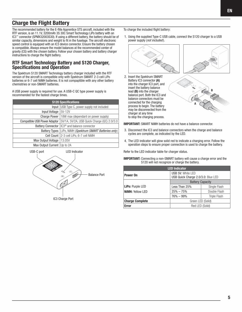
To charge the included flight battery:
1. Using the supplied Type-C USB cable, connect the S120 charger to a USB power supply (not included ).
2. Insert the Spektrum SMART Battery IC3 connector (A) into the charger IC3 port, and insert the battery balance lead (B) into the charger balance port. Both the IC3 and balance connectors must be connected for the charging process to begin. The battery may be disconnected from the charger at any time to stop the charging process.
IMPORTANT: SMART NiMH batteries do not have a balance connector.
3. Disconnect the IC3 and balance connectors when the charge and balance cycles are complete, as indicated by the LED.
4. The LED indicator will glow solid red to indicate a charging error. Follow the operation steps to ensure proper connection is used to charge the battery.
Refer to the LED indicator table for charger status.
IMPORTANT: Connecting a non-SMART battery will cause a charge error and the S120 will not recognize or charge the battery.
S120 SpecificationsInput USB Type C, power supply not included
Input Voltage 5V-12VCharge Power 18W max (dependant on power supply)
Compatible USB Power Adaptor 5V/1A, 5V/2A, USB Quick Charge (QC) 2.0/3.0Battery Connector IC3® and balance connector
Battery Types LiPo, NiMH (Spektrum SMART Batteries only )Cell Count 2-3 cell LiPo, 6-7 cell NiMH
Max Output Voltage 13.05VMax Output Current Up to 2A
LED Indicator
Power On USB 5V: White LED USB Quick Charge 2.0/3.0: Blue LED
LiPo: Purple LED
NiMH: Yellow LED
Battery CapacityLess Than 25% Single Flash25% – 75% Double Flash76% – 99% Triple Flash
Charge Complete Green LED (Solid)Error Red LED (Solid)
USB-C port LED Indicator
Balance Port
IC3 Charge Port
Charge the Flight Battery
EN
Apprentice STS6
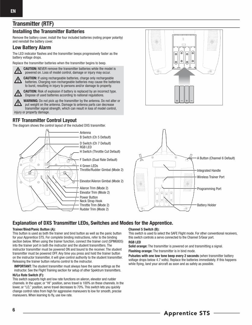
Transmitter (RTF)Installing the Transmitter BatteriesRemove the battery cover, install the four included batteries (noting proper polarity) and reinstall the battery cover.
Low Battery AlarmThe LED indicator flashes and the transmitter beeps progressively faster as the battery voltage drops.
Replace the transmitter batteries when the transmitter begins to beep.
CAUTION: NEVER remove the transmitter batteries while the model is powered on. Loss of model control, damage or injury may occur.
CAUTION: If using rechargeable batteries, charge only rechargeable batteries. Charging non-rechargeable batteries may cause the batteries to burst, resulting in injury to persons and/or damage to property.
CAUTION: Risk of explosion if battery is replaced by an incorrect type. Dispose of used batteries according to national regulations.
WARNING: Do not pick up the transmitter by the antenna. Do not alter or put weight on the antenna. Damage to antenna parts can decrease transmitter signal strength, which can result in loss of model control,
injury or property damage.
RTF Transmitter Control LayoutThe diagram shows the control layout of the included DXS transmitter.
AntennaB Switch (Ch 5 Default)
D Switch (Ch 7 Default)RGB LED H Switch (Throttle Cut Default)
F Switch (Dual Rate Default)
4 Green LEDsThrottle/Rudder Gimbal (Mode 2)
Aileron Trim (Mode 2)Elevator Trim (Mode 2)Power ButtonNeck Strap HookThrottle Trim (Mode 2)
Elevator/Aileron Gimbal (Mode 2)
A Button (Channel 6 Default)
Rudder Trim (Mode 2)
Integrated Handle
Wireless Trainer Port
Programming Port
Battery Holder
Explanation of DXS Transmitter LEDs, Switches and Modes for the Apprentice.Trainer/Bind/Panic Button (A):This button is used as both the trainer and bind button as well as the panic button for your Apprentice STS. For complete binding instructions, refer to the binding section below. When using the trainer function, connect the trainer cord (SPM6805) into the trainer port in both the instructor and the student transmitters. The instructor transmitter must be powered ON and bound to the receiver. The student transmitter must be powered OFF. Any time you press and hold the trainer button on the instructor transmitter, it will give control authority to the student transmitter. Releasing the trainer button returns control to the instructor. IMPORTANT: The student transmitter must always have the same settings as the instructor. See the Flight Training section for setup of other Spektrum transmitters.
Hi/Lo Rate Switch (F): This switch supports high and low rate functions on aileron, elevator and rudder channels. In the upper, or “HI” position, servo travel is 100% on these channels. In the lower, or “LO,” position, servo travel decreases to 70%. This switch lets you quickly change control rates from high for aggressive maneuvers to low for smooth, precise maneuvers. When learning to fly, use low rate.
Channel 5 Switch (B): This switch is used to select the SAFE Flight mode. For other conventional receivers, this switch controls a servo connected to the Channel 5/Gear port.RGB LEDSolid orange: The transmitter is powered on and transmitting a signal.Flashing orange: The transmitter is in bind mode.Pulsates with one low tone beep every 2 seconds (when transmitter battery voltage drops below 4.7 volts). Replace the batteries immediately. If this happens while flying, land your aircraft as soon and as safely as possible.
EN
7
Computerized Transmitter Setup (DX6 Gen2, DX6e,DX7 Gen2, DX8 Gen2, DX9, iX12, DX18 and DX20)
Start all transmitter programming with a blank model (do a model reset), then name the model.
Set Aileron, Elevator, and Rudder Rates to:
HIGH 100% LOW 70%
DX6DX6eDX8DX9iX12DX20NX6NX8NX10
Go to the SYSTEM SETUPSet MODEL TYPE: AIRPLANE Go to CHANNEL ASSIGN: click NEXT to go to Channel Input Config: GEAR: B, AUX1: IGo to the FUNCTION LISTGo to Throttle Cut: set to Switch H, Position: –100
Resulting in:
Switch H operates Throttle Cut, position 0 is normal and position 1 cuts power to the throttle. Switch B operates the 3 SAFE modes (0 beginner/1 intermediate/2 experienced).
Button I operates PANIC mode.
If using any DSMX transmitter other than the DXS included in the RTF version, the transmitter will have to be configured correctly for the SAFE system to work properly.
• SAFE Flight mode is selected using Channel 5 signal (high, middle, low)
• Panic mode is selected with Channel 6 signal (high, low)
Refer to your transmitter’s manual for more information about transmitter setup.
If using a 2 position switch for SAFE flight modes, only Beginner and Experienced modes will be active.
Any DXS Transmitter that was not included with a EFL Apprentice STS RTF will need to be programmed using the Spektrum Programmer (SPMA3065) to function correctly with this aircraft. Visit www.spektrumrc.com to download the correct program for this aircraft.
BNF Transmitter Telemetry SetupIf the transmitter that you intend to use with this aircraft is not displaying telemetry data, visit Spektrumrc.com and update your firmware. With the latest firmware installed on your transmitter the telemetry option should now be functional on your transmitter.
The included DSMX® full range transmitter features dual rates to allow you to select the amount of travel that you want from the control surfaces.
Dual Rate High Rate Low RateAileron 100% 70%Elevator 100% 70%Rudder 100% 70%
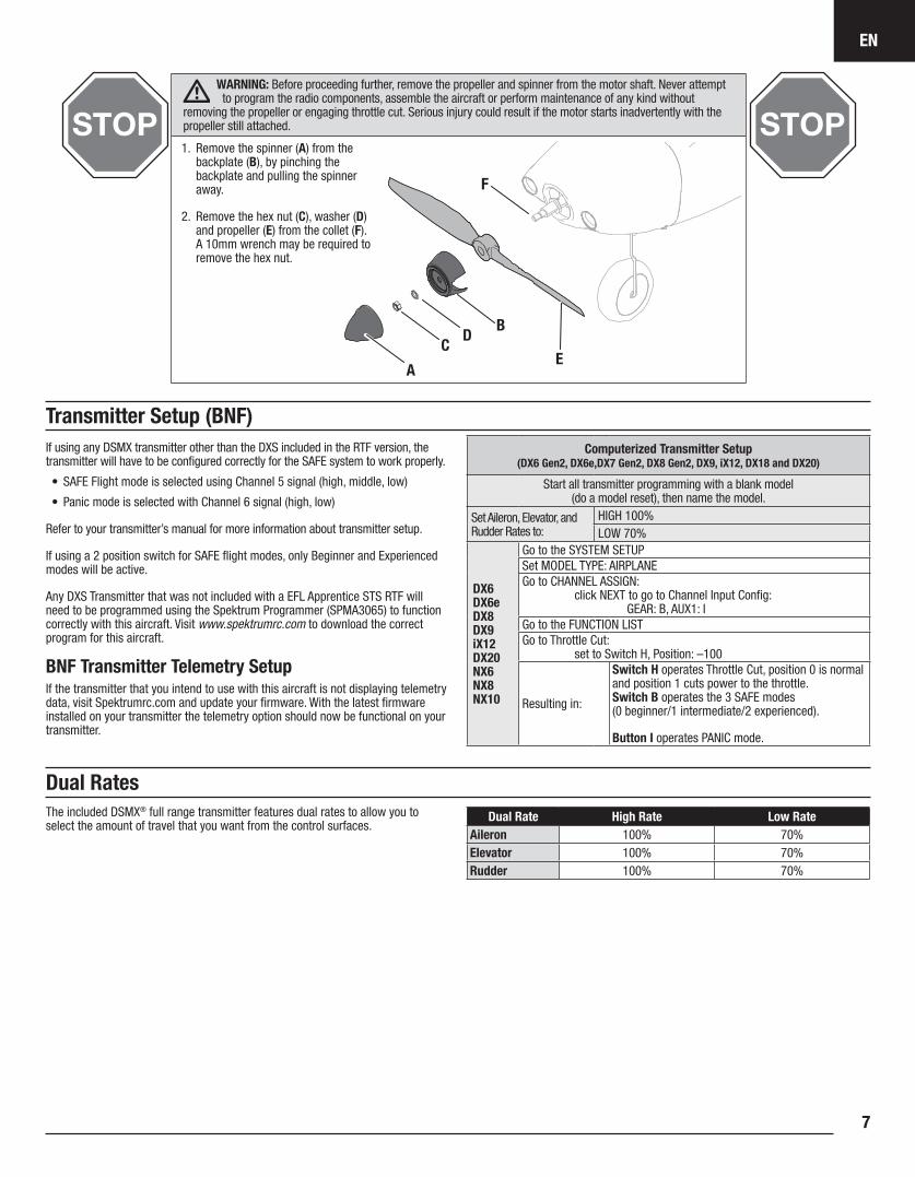
WARNING: Before proceeding further, remove the propeller and spinner from the motor shaft. Never attempt to program the radio components, assemble the aircraft or perform maintenance of any kind without
removing the propeller or engaging throttle cut. Serious injury could result if the motor starts inadvertently with the propeller still attached.
B
A
CD
E
F
1. Remove the spinner (A) from the backplate (B), by pinching the backplate and pulling the spinner away.
2. Remove the hex nut (C), washer (D) and propeller (E) from the collet (F). A 10mm wrench may be required to remove the hex nut.
Transmitter Setup (BNF)
Dual Rates
EN
Apprentice STS8
Assemble the Aircraft
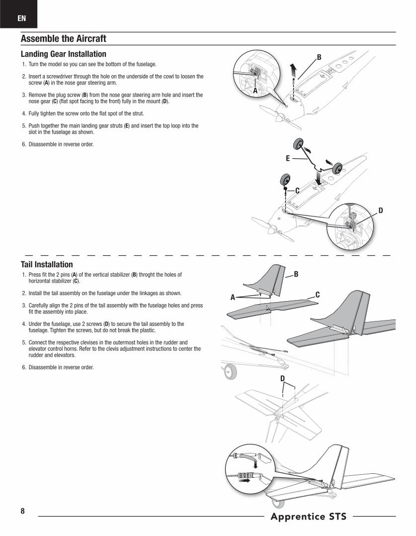
Landing Gear Installation1. Turn the model so you can see the bottom of the fuselage.
2. Insert a screwdriver through the hole on the underside of the cowl to loosen the screw (A) in the nose gear steering arm.
3. Remove the plug screw (B) from the nose gear steering arm hole and insert the nose gear (C) (flat spot facing to the front) fully in the mount (D).
4. Fully tighten the screw onto the flat spot of the strut.
5. Push together the main landing gear struts (E) and insert the top loop into the slot in the fuselage as shown.
6. Disassemble in reverse order.
A
D
C
E
Tail Installation1. Press fit the 2 pins (A) of the vertical stabilizer (B) throght the holes of
horizontal stabilizer (C).
2. Install the tail assembly on the fuselage under the linkages as shown.
3. Carefully align the 2 pins of the tail assembly with the fuselage holes and press fit the assembly into place.
4. Under the fuselage, use 2 screws (D) to secure the tail assembly to the fuselage. Tighten the screws, but do not break the plastic.
5. Connect the respective clevises in the outermost holes in the rudder and elevator control horns. Refer to the clevis adjustment instructions to center the rudder and elevators.
6. Disassemble in reverse order.
A
D
B
C
B
EN
9
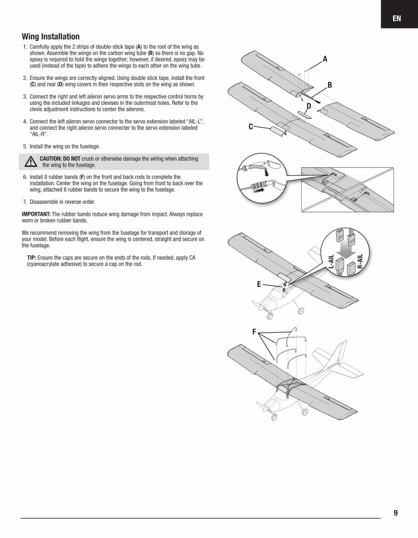
Wing Installation1. Carefully apply the 2 strips of double-stick tape (A) to the root of the wing as
shown. Assemble the wings on the carbon wing tube (B) so there is no gap. No epoxy is required to hold the wings together; however, if desired, epoxy may be used (instead of the tape) to adhere the wings to each other on the wing tube.
2. Ensure the wings are correctly aligned. Using double stick tape, install the front (C) and rear (D) wing covers in their respective slots on the wing as shown.
3. Connect the right and left aileron servo arms to the respective control horns by using the included linkages and clevises in the outermost holes. Refer to the clevis adjustment instructions to center the ailerons.
4. Connect the left aileron servo connector to the servo extension labeled “AIL-L”, and connect the right aileron servo connecter to the servo extension labeled “AIL-R”.
5. Install the wing on the fuselage.
CAUTION: DO NOT crush or otherwise damage the wiring when attaching the wing to the fuselage.
6. Install 8 rubber bands (F) on the front and back rods to complete the installation. Center the wing on the fuselage. Going from front to back over the wing, attached 8 rubber bands to secure the wing to the fuselage.
7. Disassemble in reverse order.
IMPORTANT: The rubber bands reduce wing damage from impact. Always replace worn or broken rubber bands.
We recommend removing the wing from the fuselage for transport and storage of your model. Before each flight, ensure the wing is centered, straight and secure on the fuselage.
TIP: Ensure the caps are secure on the ends of the rods. If needed, apply CA (cyanoacrylate adhesive) to secure a cap on the rod.
E
F
B
A
D
C
R-AI
L
L-AI
L
EN
Apprentice STS10
Transmitter and Receiver Binding
Binding is the process of programming the control unit to recognize the GUID (Globally Unique Identifier) code of a single specific transmitter.
The aircraft should be bound to the transmitter at the factory, but if you need to re-bind them, follow these steps. If your aircraft does not respond to the transmitter when the batteries in the aircraft and transmitter are fully charged, your aircraft and transmitter may need to be re-bound using the instructions below.
Please refer to the optional parts list in this manual or visit www.bindnfly.com for a list of compatible transmitters. For the BNF aircraft, you need to ‘bind’ your chosen Spektrum™ DSMX® technology equipped aircraft transmitter to the receiver for proper operation.
IMPORTANT: The throttle will not arm if the transmitter’s throttle control is not put at the lowest position. If you encounter problems, follow the binding instructions and refer to the transmitter troubleshooting guide for other instructions. If needed, contact the appropriate Horizon Product Support office.
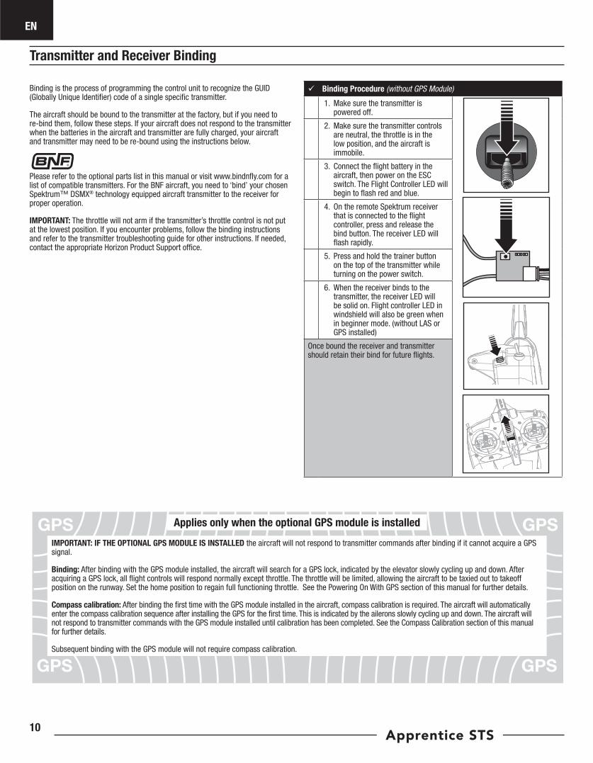
Binding Procedure (without GPS Module)
1. Make sure the transmitter is powered off.
2. Make sure the transmitter controls are neutral, the throttle is in the low position, and the aircraft is immobile.
3. Connect the flight battery in the aircraft, then power on the ESC switch. The Flight Controller LED will begin to flash red and blue.
4. On the remote Spektrum receiver that is connected to the flight controller, press and release the bind button. The receiver LED will flash rapidly.
5. Press and hold the trainer button on the top of the transmitter while turning on the power switch.
6. When the receiver binds to the transmitter, the receiver LED will be solid on. Flight controller LED in windshield will also be green when in beginner mode. (without LAS or GPS installed)
Once bound the receiver and transmitter should retain their bind for future flights.
IMPORTANT: IF THE OPTIONAL GPS MODULE IS INSTALLED the aircraft will not respond to transmitter commands after binding if it cannot acquire a GPS signal.
Binding: After binding with the GPS module installed, the aircraft will search for a GPS lock, indicated by the elevator slowly cycling up and down. After acquiring a GPS lock, all flight controls will respond normally except throttle. The throttle will be limited, allowing the aircraft to be taxied out to takeoff position on the runway. Set the home position to regain full functioning throttle. See the Powering On With GPS section of this manual for further details.
Compass calibration: After binding the first time with the GPS module installed in the aircraft, compass calibration is required. The aircraft will automatically enter the compass calibration sequence after installing the GPS for the first time. This is indicated by the ailerons slowly cycling up and down. The aircraft will not respond to transmitter commands with the GPS module installed until calibration has been completed. See the Compass Calibration section of this manual for further details.
Subsequent binding with the GPS module will not require compass calibration.
Applies only when the optional GPS module is installed
EN
11
Flight Battery Installation, SAFE system and Electronic Speed Control (ESC) Arming
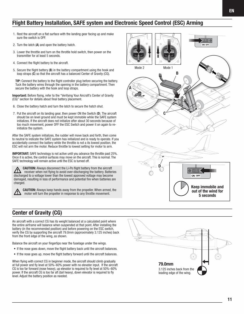
1. Rest the aircraft on a flat surface with the landing gear facing up and make sure the switch is OFF.
2. Turn the latch (A) and open the battery hatch.
3. Lower the throttle and turn on the throttle hold switch, then power on the transmitter for at least 5 seconds.
4. Connect the flight battery to the aircraft.
5. Secure the flight battery (B) in the battery compartment using the hook and loop straps (C) so that the aircraft has a balanced Center of Gravity (CG).
TIP: Connect the battery to the flight controller plug before securing the battery. Tuck the battery wires through the opening in the battery compartment. Then secure the battery with the hook and loop straps.
Important: Before flying, refer to the “Verifying Your Aircraft’s Center of Gravity (CG)” section for details about final battery placement.
6. Close the battery hatch and turn the latch to secure the hatch shut.
7. Put the aircraft on its landing gear, then power ON the Switch (D). The aircraft should be on level ground and must be kept immobile while the SAFE system initializes. If the aircraft does not initialize after about 30 seconds because of too much movement, power OFF the ESC Switch and power it on again to re-initialize the system.
After the SAFE system initializes, the rudder will move back and forth, then come to neutral to indicate the SAFE system has initialized and is ready to operate. If you accidentally connect the battery while the throttle is not a its lowest position, the ESC will not arm the motor. Reduce throttle to lowest setting for motor to arm.
IMPORTANT: SAFE technology is not active until you advance the throttle past 25%. Once it is active, the control surfaces may move on the aircraft. This is normal. The SAFE technology will remain active until the ESC is turned off.
CAUTION: Always disconnect the Li-Po flight battery from the aircraft receiver when not flying to avoid over-discharging the battery. Batteries
discharged to a voltage lower than the lowest approved voltage may become damaged, resulting in loss of performance and potential fire when batteries are charged.
CAUTION: Always keep hands away from the propeller. When armed, the motor will turn the propeller in response to any throttle movement.
Mode 2 Mode 1
Keep immobile and out of the wind for
5 seconds
A
B
D
C
Center of Gravity (CG)An aircraft with a correct CG has its weight balanced at a calculated point where the entire airframe will balance when suspended at that point. After installing the battery (in the recommended position) and before powering on the ESC switch, verify the CG by supporting the aircraft 79.0mm (approximately 3.125 inches) back from the front edge of the wing, as shown.
Balance the aircraft on your fingertips near the fuselage under the wings.
• If the nose goes down, move the flight battery back until the aircraft balances.
• If the nose goes up, move the flight battery forward until the aircraft balances.
When flying with correct CG in beginner mode, the aircraft should climb gradually at full power and fly level at 50%–60% power with no elevator input. If the aircraft CG is too far forward (nose heavy), up elevator is required to fly level at 50%–60% power. If the aircraft CG is too far aft (tail heavy), down elevator is required to fly level. Adjust the battery position as needed.
79.0mm3.125 inches back from the leading edge of the wing.
EN
Apprentice STS12
Control Direction Test
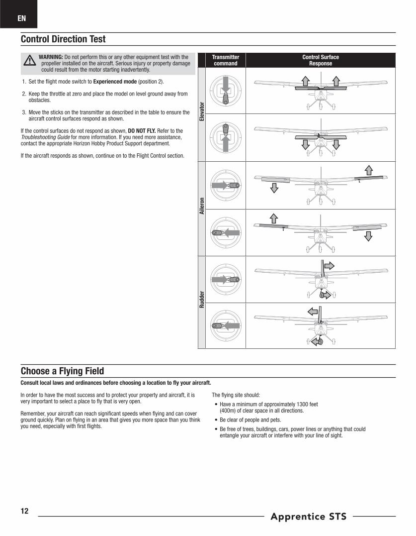
Choose a Flying FieldConsult local laws and ordinances before choosing a location to fly your aircraft.
In order to have the most success and to protect your property and aircraft, it is very important to select a place to fly that is very open.
Remember, your aircraft can reach significant speeds when flying and can cover ground quickly. Plan on flying in an area that gives you more space than you think you need, especially with first flights.
The flying site should:
• Have a minimum of approximately 1300 feet (400m) of clear space in all directions.
• Be clear of people and pets.
• Be free of trees, buildings, cars, power lines or anything that could entangle your aircraft or interfere with your line of sight.
WARNING: Do not perform this or any other equipment test with the propeller installed on the aircraft. Serious injury or property damage could result from the motor starting inadvertently.
1. Set the flight mode switch to Experienced mode (position 2).
2. Keep the throttle at zero and place the model on level ground away from obstacles.
3. Move the sticks on the transmitter as described in the table to ensure the aircraft control surfaces respond as shown.
If the control surfaces do not respond as shown, DO NOT FLY. Refer to the Troubleshooting Guide for more information. If you need more assistance, contact the appropriate Horizon Hobby Product Support department.
If the aircraft responds as shown, continue on to the Flight Control section.
Transmitter command
Control Surface Response
Elev
ator
Aile
ron
Rudd
er
EN
13
Range Test
WARNING: Do not perform this or any other equipment test with the propeller installed on the aircraft. Serious injury or property damage could result from the motor starting inadvertently.
WARNING: While holding the aircraft during the range test, always keep body parts and loose items away from the motor. Failure to do so could cause personal injury.
Before each flying session, and especially with a new model, you should perform a range check. If you have the BNF aircraft, refer to your transmitter manual to perform a range check of your system.
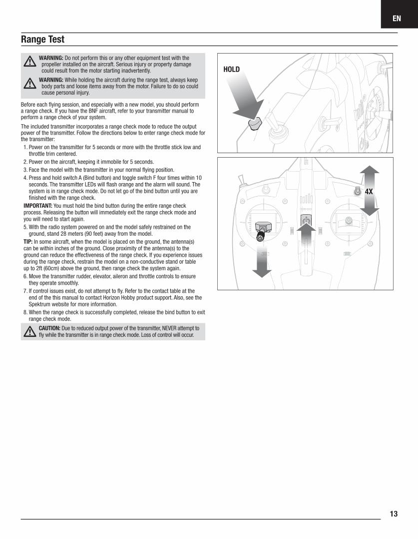
The included transmitter incorporates a range check mode to reduce the output power of the transmitter. Follow the directions below to enter range check mode for the transmitter:1. Power on the transmitter for 5 seconds or more with the throttle stick low and
throttle trim centered.2. Power on the aircraft, keeping it immobile for 5 seconds.3. Face the model with the transmitter in your normal flying position.4. Press and hold switch A (Bind button) and toggle switch F four times within 10
seconds. The transmitter LEDs will flash orange and the alarm will sound. The system is in range check mode. Do not let go of the bind button until you are finished with the range check.
IMPORTANT: You must hold the bind button during the entire range check process. Releasing the button will immediately exit the range check mode and you will need to start again.5. With the radio system powered on and the model safely restrained on the
ground, stand 28 meters (90 feet) away from the model.TIP: In some aircraft, when the model is placed on the ground, the antenna(s) can be within inches of the ground. Close proximity of the antenna(s) to the ground can reduce the effectiveness of the range check. If you experience issues during the range check, restrain the model on a non-conductive stand or table up to 2ft (60cm) above the ground, then range check the system again.6. Move the transmitter rudder, elevator, aileron and throttle controls to ensure
they operate smoothly.7. If control issues exist, do not attempt to fly. Refer to the contact table at the
end of the this manual to contact Horizon Hobby product support. Also, see the Spektrum website for more information.
8. When the range check is successfully completed, release the bind button to exit range check mode.
CAUTION: Due to reduced output power of the transmitter, NEVER attempt to fly while the transmitter is in range check mode. Loss of control will occur.
HOLD
4X
EN
Apprentice STS14
WARNING: Do not install the propeller until the aircraft has been completely assembled, all the systems have been checked thoroughly and you are located at a suitable flying site.
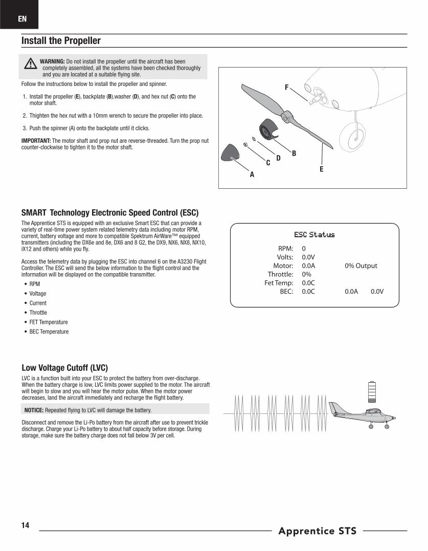
Follow the instructions below to install the propeller and spinner.
1. Install the propeller (E), backplate (B),washer (D), and hex nut (C) onto the motor shaft.
2. Thighten the hex nut with a 10mm wrench to secure the propeller into place.
3. Push the spinner (A) onto the backplate until it clicks.
IMPORTANT: The motor shaft and prop nut are reverse-threaded. Turn the prop nut counter-clockwise to tighten it to the motor shaft.
B
A
CD
E
F
SMART Technology Electronic Speed Control (ESC)The Apprentice STS is equipped with an exclusive Smart ESC that can provide a variety of real-time power system related telemetry data including motor RPM, current, battery voltage and more to compatible Spektrum AirWare™ equipped transmitters (including the DX6e and 8e, DX6 and 8 G2, the DX9, NX6, NX8, NX10, iX12 and others) while you fly.
Access the telemetry data by plugging the ESC into channel 6 on the A3230 Flight Controller. The ESC will send the below information to the flight control and the information will be displayed on the compatible transmitter.
• RPM
• Voltage
• Current
• Throttle
• FET Temperature
• BEC Temperature
RPM:Volts:
Motor:Throttle:
Fet Temp:BEC:
00.0V0.0A 0% Output0%0.0C0.0C 0.0A 0.0V
Low Voltage Cutoff (LVC)LVC is a function built into your ESC to protect the battery from over-discharge. When the battery charge is low, LVC limits power supplied to the motor. The aircraft will begin to slow and you will hear the motor pulse. When the motor power decreases, land the aircraft immediately and recharge the flight battery.
NOTICE: Repeated flying to LVC will damage the battery.
Disconnect and remove the Li-Po battery from the aircraft after use to prevent trickle discharge. Charge your Li-Po battery to about half capacity before storage. During storage, make sure the battery charge does not fall below 3V per cell.
Install the Propeller
EN
15
Flying
RollPitch
RollPitch
RollPitch
0 1
2
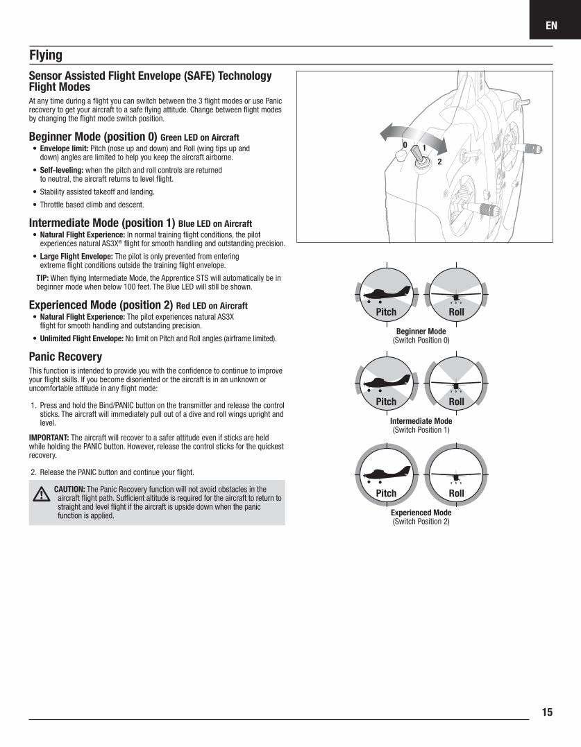
Sensor Assisted Flight Envelope (SAFE) Technology Flight ModesAt any time during a flight you can switch between the 3 flight modes or use Panic recovery to get your aircraft to a safe flying attitude. Change between flight modes by changing the flight mode switch position.
Beginner Mode (position 0) Green LED on Aircraft • Envelope limit: Pitch (nose up and down) and Roll (wing tips up and
down) angles are limited to help you keep the aircraft airborne.
• Self-leveling: when the pitch and roll controls are returned to neutral, the aircraft returns to level flight.
• Stability assisted takeoff and landing.
• Throttle based climb and descent.
Intermediate Mode (position 1) Blue LED on Aircraft • Natural Flight Experience: In normal training flight conditions, the pilot
experiences natural AS3X® flight for smooth handling and outstanding precision.
• Large Flight Envelope: The pilot is only prevented from entering extreme flight conditions outside the training flight envelope.
TIP: When flying Intermediate Mode, the Apprentice STS will automatically be in beginner mode when below 100 feet. The Blue LED will still be shown.
Experienced Mode (position 2) Red LED on Aircraft • Natural Flight Experience: The pilot experiences natural AS3X
flight for smooth handling and outstanding precision.
• Unlimited Flight Envelope: No limit on Pitch and Roll angles (airframe limited).
Panic RecoveryThis function is intended to provide you with the confidence to continue to improve your flight skills. If you become disoriented or the aircraft is in an unknown or uncomfortable attitude in any flight mode:
1. Press and hold the Bind/PANIC button on the transmitter and release the control sticks. The aircraft will immediately pull out of a dive and roll wings upright and level.
IMPORTANT: The aircraft will recover to a safer attitude even if sticks are held while holding the PANIC button. However, release the control sticks for the quickest recovery.
2. Release the PANIC button and continue your flight.
CAUTION: The Panic Recovery function will not avoid obstacles in the aircraft flight path. Sufficient altitude is required for the aircraft to return to straight and level flight if the aircraft is upside down when the panic function is applied.
Beginner Mode (Switch Position 0)
Intermediate Mode (Switch Position 1)
Experienced Mode (Switch Position 2)
EN
Apprentice STS16
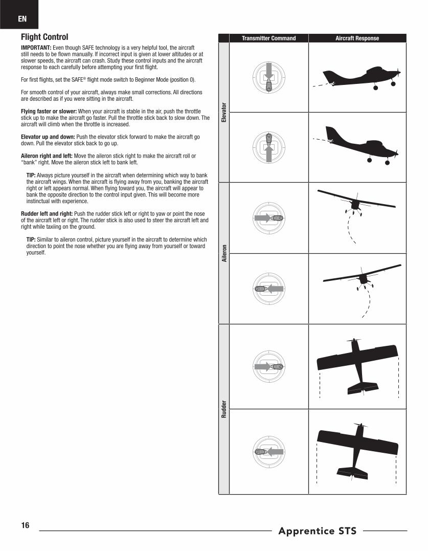
Flight Control IMPORTANT: Even though SAFE technology is a very helpful tool, the aircraft still needs to be flown manually. If incorrect input is given at lower altitudes or at slower speeds, the aircraft can crash. Study these control inputs and the aircraft response to each carefully before attempting your first flight.
For first flights, set the SAFE® flight mode switch to Beginner Mode (position 0).
For smooth control of your aircraft, always make small corrections. All directions are described as if you were sitting in the aircraft.
Flying faster or slower: When your aircraft is stable in the air, push the throttle stick up to make the aircraft go faster. Pull the throttle stick back to slow down. The aircraft will climb when the throttle is increased.
Elevator up and down: Push the elevator stick forward to make the aircraft go down. Pull the elevator stick back to go up.
Aileron right and left: Move the aileron stick right to make the aircraft roll or “bank” right. Move the aileron stick left to bank left.
TIP: Always picture yourself in the aircraft when determining which way to bank the aircraft wings. When the aircraft is flying away from you, banking the aircraft right or left appears normal. When flying toward you, the aircraft will appear to bank the opposite direction to the control input given. This will become more instinctual with experience.
Rudder left and right: Push the rudder stick left or right to yaw or point the nose of the aircraft left or right. The rudder stick is also used to steer the aircraft left and right while taxiing on the ground.
TIP: Similar to aileron control, picture yourself in the aircraft to determine which direction to point the nose whether you are flying away from yourself or toward yourself.
Transmitter Command Aircraft Response
Elev
ator
Aile
ron
Rudd
er
EN
17
Flight TrainingInstruction
To the new pilot: This aircraft is easy to fly and helps you apply beginner skills to flying; however, we recommend you get help from a qualified flight instructor for your first radio controlled flights. Some model flying clubs provide flight training at their flying fields. Find a nearby flying club through your local hobby shop. In the U.S., visit the Academy of Model Aeronautics at www.modelaircraft.org. for more information on clubs and flight instruction.
To the flight instructor: Feel free to experiment with the SAFE technology before instructing your student on this aircraft. The progressive switch positions in the SAFE technology are intended for a new pilot to learn with minimal instructor assistance. We recommend using Channel 5 Switch Position 1 to instruct a new pilot. Switch positions 0 and 2 may stabilize the aircraft more or less than you desire for instruction purposes.
Buddy Box Flight TrainingThe “buddy box” approach has helped many new pilots get the feel for aircraft control with the close assistance of a flight instructor. Connecting two transmitters enables your flight instructor to hold the “Instructor” transmitter while you hold the “Student” transmitter. While you learn to fly, the instructor holds the trainer switch, giving you control of the aircraft. If you need help, the flight instructor releases the switch to take control.
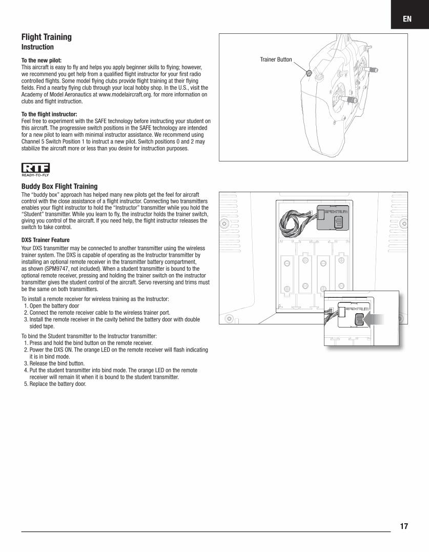
DXS Trainer FeatureYour DXS transmitter may be connected to another transmitter using the wireless trainer system. The DXS is capable of operating as the Instructor transmitter by installing an optional remote receiver in the transmitter battery compartment, as shown (SPM9747, not included). When a student transmitter is bound to the optional remote receiver, pressing and holding the trainer switch on the instructor transmitter gives the student control of the aircraft. Servo reversing and trims must be the same on both transmitters.
To install a remote receiver for wireless training as the Instructor:1. Open the battery door2. Connect the remote receiver cable to the wireless trainer port.3. Install the remote receiver in the cavity behind the battery door with double
sided tape.
To bind the Student transmitter to the Instructor transmitter:1. Press and hold the bind button on the remote receiver.2. Power the DXS ON. The orange LED on the remote receiver will flash indicating
it is in bind mode.3. Release the bind button.4. Put the student transmitter into bind mode. The orange LED on the remote
receiver will remain lit when it is bound to the student transmitter.5. Replace the battery door.
Trainer Button
EN
Apprentice STS18
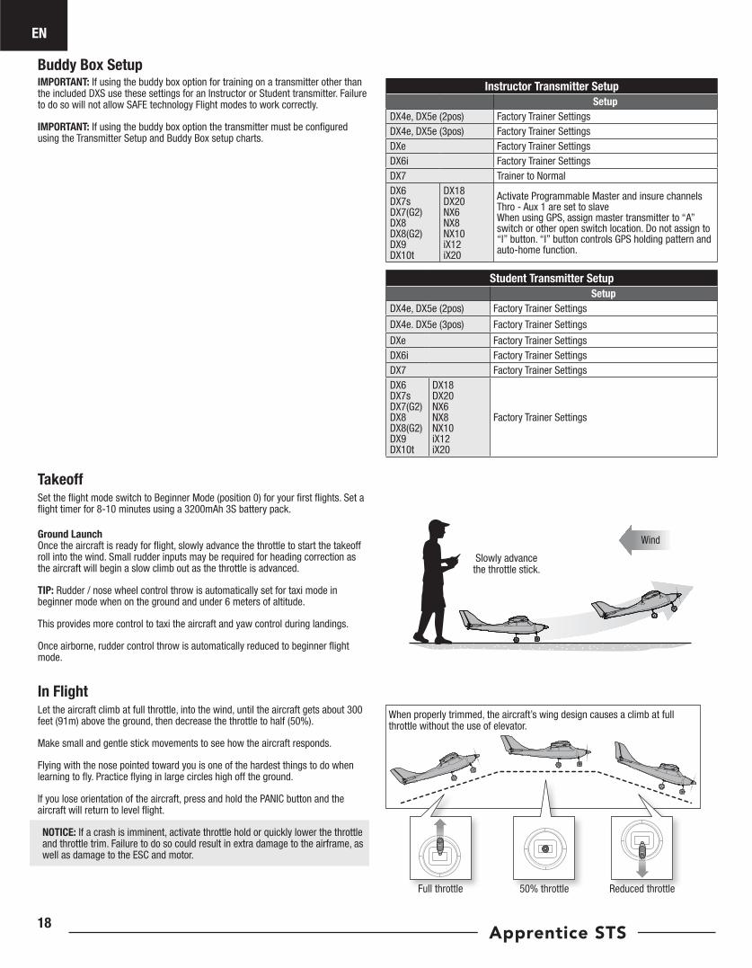
TakeoffSet the flight mode switch to Beginner Mode (position 0) for your first flights. Set a flight timer for 8-10 minutes using a 3200mAh 3S battery pack.
Ground Launch Once the aircraft is ready for flight, slowly advance the throttle to start the takeoff roll into the wind. Small rudder inputs may be required for heading correction as the aircraft will begin a slow climb out as the throttle is advanced.
TIP: Rudder / nose wheel control throw is automatically set for taxi mode in beginner mode when on the ground and under 6 meters of altitude.
This provides more control to taxi the aircraft and yaw control during landings.
Once airborne, rudder control throw is automatically reduced to beginner flight mode.
Slowly advance the throttle stick.
Wind
When properly trimmed, the aircraft’s wing design causes a climb at full throttle without the use of elevator.
50% throttleFull throttle Reduced throttle
In FlightLet the aircraft climb at full throttle, into the wind, until the aircraft gets about 300 feet (91m) above the ground, then decrease the throttle to half (50%).
Make small and gentle stick movements to see how the aircraft responds.
Flying with the nose pointed toward you is one of the hardest things to do when learning to fly. Practice flying in large circles high off the ground.
If you lose orientation of the aircraft, press and hold the PANIC button and the aircraft will return to level flight.
NOTICE: If a crash is imminent, activate throttle hold or quickly lower the throttle and throttle trim. Failure to do so could result in extra damage to the airframe, as well as damage to the ESC and motor.
IMPORTANT: If using the buddy box option for training on a transmitter other than the included DXS use these settings for an Instructor or Student transmitter. Failure to do so will not allow SAFE technology Flight modes to work correctly.
IMPORTANT: If using the buddy box option the transmitter must be configured using the Transmitter Setup and Buddy Box setup charts.
Instructor Transmitter SetupSetup
DX4e, DX5e (2pos) Factory Trainer SettingsDX4e, DX5e (3pos) Factory Trainer SettingsDXe Factory Trainer SettingsDX6i Factory Trainer SettingsDX7 Trainer to NormalDX6 DX7s DX7(G2) DX8 DX8(G2) DX9 DX10t
DX18 DX20 NX6 NX8 NX10 iX12 iX20
Activate Programmable Master and insure channels Thro - Aux 1 are set to slaveWhen using GPS, assign master transmitter to “A” switch or other open switch location. Do not assign to “I” button. “I” button controls GPS holding pattern and auto-home function.
Buddy Box Setup
Student Transmitter SetupSetup
DX4e, DX5e (2pos) Factory Trainer Settings
DX4e. DX5e (3pos) Factory Trainer Settings
DXe Factory Trainer SettingsDX6i Factory Trainer SettingsDX7 Factory Trainer SettingsDX6 DX7s DX7(G2) DX8 DX8(G2) DX9 DX10t
DX18 DX20 NX6 NX8 NX10 iX12 iX20
Factory Trainer Settings
EN
19
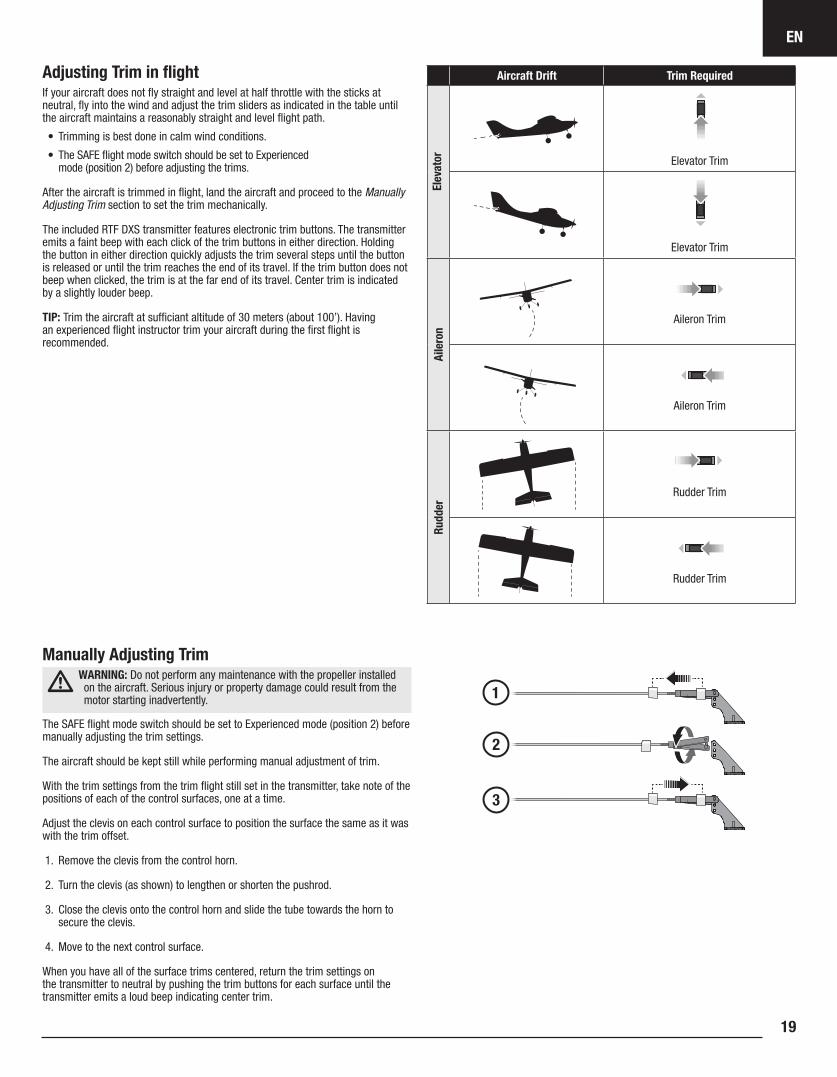
Adjusting Trim in flightIf your aircraft does not fly straight and level at half throttle with the sticks at neutral, fly into the wind and adjust the trim sliders as indicated in the table until the aircraft maintains a reasonably straight and level flight path.
• Trimming is best done in calm wind conditions.
• The SAFE flight mode switch should be set to Experienced mode (position 2) before adjusting the trims.
After the aircraft is trimmed in flight, land the aircraft and proceed to the Manually Adjusting Trim section to set the trim mechanically.
The included RTF DXS transmitter features electronic trim buttons. The transmitter emits a faint beep with each click of the trim buttons in either direction. Holding the button in either direction quickly adjusts the trim several steps until the button is released or until the trim reaches the end of its travel. If the trim button does not beep when clicked, the trim is at the far end of its travel. Center trim is indicated by a slightly louder beep.
TIP: Trim the aircraft at sufficiant altitude of 30 meters (about 100’). Having an experienced flight instructor trim your aircraft during the first flight is recommended.
Aircraft Drift Trim Required
Elev
ator Elevator Trim
Elevator Trim
Aile
ron
Aileron Trim
Aileron Trim
Rudd
er
Rudder Trim
Rudder Trim
Manually Adjusting Trim WARNING: Do not perform any maintenance with the propeller installed on the aircraft. Serious injury or property damage could result from the motor starting inadvertently.
The SAFE flight mode switch should be set to Experienced mode (position 2) before manually adjusting the trim settings.
The aircraft should be kept still while performing manual adjustment of trim.
With the trim settings from the trim flight still set in the transmitter, take note of the positions of each of the control surfaces, one at a time.
Adjust the clevis on each control surface to position the surface the same as it was with the trim offset.
1. Remove the clevis from the control horn.
2. Turn the clevis (as shown) to lengthen or shorten the pushrod.
3. Close the clevis onto the control horn and slide the tube towards the horn to secure the clevis.
4. Move to the next control surface.
When you have all of the surface trims centered, return the trim settings on the transmitter to neutral by pushing the trim buttons for each surface until the transmitter emits a loud beep indicating center trim.
EN
Apprentice STS20
IMPORTANT: We recommend flying with floats only once you have become able to fly comfortably in Experienced flight mode.
Only use the floats if you are comfortable flying your aircraft and have repeatedly taken off, flown and landed with success. Flying off water poses a higher risk to the airplane because the electronics can fail if fully immersed in water.
Always ensure the optional floats (ELFA550, sold separately) are secure on the fuselage and that the float rudder linkage is correctly connected and moves freely before putting the aircraft in water.
To take off on water, steer with the rudder and slowly increase the throttle. Keep the wings level on takeoff. Hold a small amount (1/4–1/3) of up elevator and the aircraft will lift off once flying speed is reached. Avoid rapidly increasing the throttle as torque from the motor may cause the aircraft to roll to the left when on water.
To land this aircraft on water, fly the aircraft to a couple of feet off the surface of the water. Reduce throttle and add up elevator to flare the aircraft.
When taxiing, you must use throttle to move the aircraft forward, but steer with the rudder stick. The stick will turn both the aircraft rudder and a small rudder attached to the left float.
Avoid taxiing cross wind if there is a breeze, as this can cause the aircraft to flip over if wind gets under the wing. Taxi 45 degrees into the direction of the wind (not perpendicular to the wind) and use aileron to hold the upwind wing down. The aircraft will naturally try to face into the wind when taxiing.
Always fully dry the aircraft after landing on water.
CAUTION: Never swim or go alone to get a downed model in the water.
CAUTION: If at any time water splashes in the fuselage while flying from water, bring the airplane to shore, open the battery hatch and
immediately remove any water that may have gotten in the fuselage. Leave the battery hatch open overnight to let the inside dry out and to prevent moisture damage to the electronic components. Failure to do so could cause the electronic components to fail, which could result in a crash.
Water Takeoff and Landing Using the Optional Float Set
45º
Up Aileron
Down Aileron
Wind
Taxi 45 degrees into the direction of the wind.
Post Flight1 Disconnect the flight battery from the ESC (Required for Safety and battery life).2 Power OFF the transmitter.3 Remove the flight battery from the aircraft.4 Recharge the flight battery.
5 Repair or replace all damaged parts.6 Store the flight battery apart from the aircraft and monitor the battery charge.7 Make note of the flight conditions and flight plan results, planning for future flights.
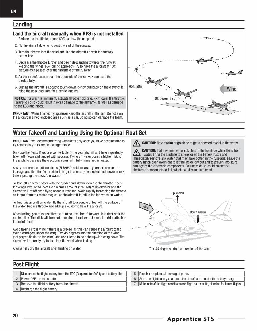
LandingLand the aircraft manually when GPS is not installed
1. Reduce the throttle to around 50% to slow the airspeed.
2. Fly the aircraft downwind past the end of the runway.
3. Turn the aircraft into the wind and line the aircraft up with the runway center line.
4. Decrease the throttle further and begin descending towards the runway, keeping the wings level during approach. Try to have the aircraft at 10ft altitude as it passes over the threshold of the runway.
5. As the aircraft passes over the threshold of the runway decrease the throttle fully.
6. Just as the aircraft is about to touch down, gently pull back on the elevator to raise the nose and flare for a gentle landing.
NOTICE: If a crash is imminent, activate throttle hold or quickly lower the throttle. Failure to do so could result in extra damage to the airframe, as well as damage to the ESC and motor.
IMPORTANT: When finished flying, never keep the aircraft in the sun. Do not store the aircraft in a hot, enclosed area such as a car. Doing so can damage the foam.
65ft (20m)
10ft power is cut
Wind
EN
21
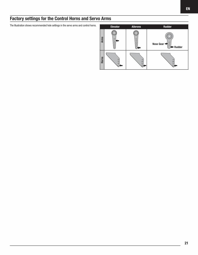
Factory settings for the Control Horns and Servo Arms
Elevator Ailerons Rudder
Arm
sHo
rns
Nose GearRudder
The Illustration shows recommended hole settings in the servo arms and control horns.
EN
Apprentice STS22
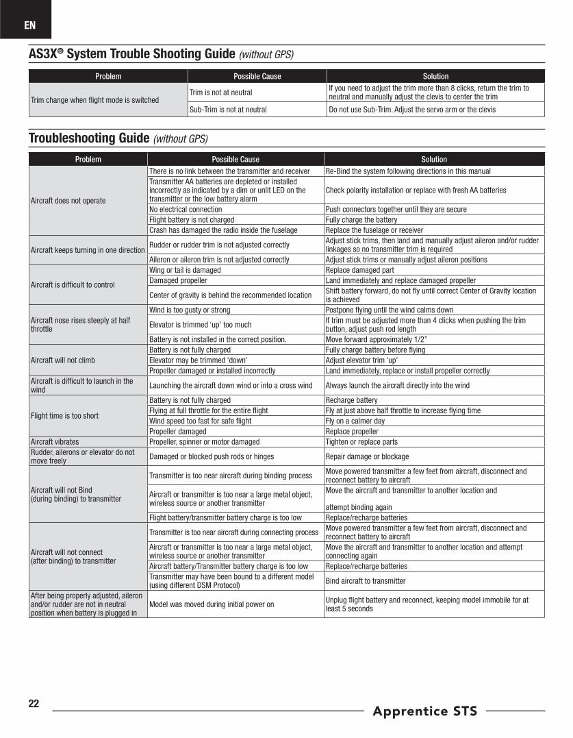
Troubleshooting Guide (without GPS)
Problem Possible Cause Solution
Trim change when flight mode is switchedTrim is not at neutral If you need to adjust the trim more than 8 clicks, return the trim to
neutral and manually adjust the clevis to center the trim
Sub-Trim is not at neutral Do not use Sub-Trim. Adjust the servo arm or the clevis
AS3X® System Trouble Shooting Guide (without GPS)
Problem Possible Cause Solution
Aircraft does not operate
There is no link between the transmitter and receiver Re-Bind the system following directions in this manualTransmitter AA batteries are depleted or installed incorrectly as indicated by a dim or unlit LED on the transmitter or the low battery alarm
Check polarity installation or replace with fresh AA batteries
No electrical connection Push connectors together until they are secureFlight battery is not charged Fully charge the batteryCrash has damaged the radio inside the fuselage Replace the fuselage or receiver
Aircraft keeps turning in one directionRudder or rudder trim is not adjusted correctly Adjust stick trims, then land and manually adjust aileron and/or rudder
linkages so no transmitter trim is requiredAileron or aileron trim is not adjusted correctly Adjust stick trims or manually adjust aileron positions
Aircraft is difficult to control
Wing or tail is damaged Replace damaged partDamaged propeller Land immediately and replace damaged propeller
Center of gravity is behind the recommended location Shift battery forward, do not fly until correct Center of Gravity location is achieved
Aircraft nose rises steeply at half throttle
Wind is too gusty or strong Postpone flying until the wind calms down
Elevator is trimmed ‘up’ too much If trim must be adjusted more than 4 clicks when pushing the trim button, adjust push rod length
Battery is not installed in the correct position. Move forward approximately 1/2”
Aircraft will not climbBattery is not fully charged Fully charge battery before flyingElevator may be trimmed ‘down’ Adjust elevator trim ‘up’ Propeller damaged or installed incorrectly Land immediately, replace or install propeller correctly
Aircraft is difficult to launch in the wind Launching the aircraft down wind or into a cross wind Always launch the aircraft directly into the wind
Flight time is too short
Battery is not fully charged Recharge batteryFlying at full throttle for the entire flight Fly at just above half throttle to increase flying timeWind speed too fast for safe flight Fly on a calmer dayPropeller damaged Replace propeller
Aircraft vibrates Propeller, spinner or motor damaged Tighten or replace partsRudder, ailerons or elevator do not move freely Damaged or blocked push rods or hinges Repair damage or blockage
Aircraft will not Bind (during binding) to transmitter
Transmitter is too near aircraft during binding process Move powered transmitter a few feet from aircraft, disconnect and reconnect battery to aircraft
Aircraft or transmitter is too near a large metal object, wireless source or another transmitter
Move the aircraft and transmitter to another location and
attempt binding againFlight battery/transmitter battery charge is too low Replace/recharge batteries
Aircraft will not connect (after binding) to transmitter
Transmitter is too near aircraft during connecting process Move powered transmitter a few feet from aircraft, disconnect and reconnect battery to aircraft
Aircraft or transmitter is too near a large metal object, wireless source or another transmitter
Move the aircraft and transmitter to another location and attempt connecting again
Aircraft battery/Transmitter battery charge is too low Replace/recharge batteriesTransmitter may have been bound to a different model (using different DSM Protocol) Bind aircraft to transmitter
After being properly adjusted, aileron and/or rudder are not in neutral position when battery is plugged in
Model was moved during initial power on Unplug flight battery and reconnect, keeping model immobile for at least 5 seconds
EN
23
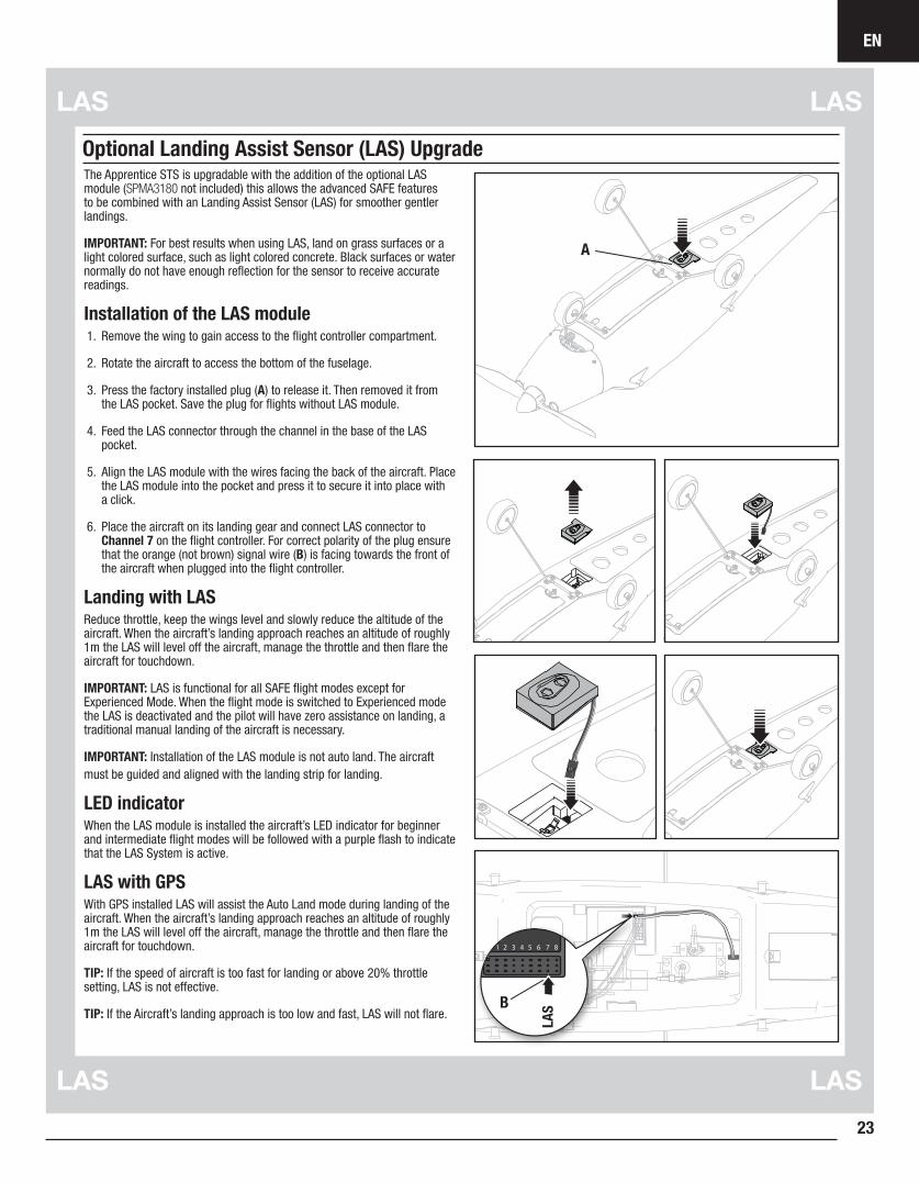
Optional Landing Assist Sensor (LAS) UpgradeThe Apprentice STS is upgradable with the addition of the optional LAS module (SPMA3180 not included) this allows the advanced SAFE features to be combined with an Landing Assist Sensor (LAS) for smoother gentler landings.
IMPORTANT: For best results when using LAS, land on grass surfaces or a light colored surface, such as light colored concrete. Black surfaces or water normally do not have enough reflection for the sensor to receive accurate readings.
Installation of the LAS module1. Remove the wing to gain access to the flight controller compartment.
2. Rotate the aircraft to access the bottom of the fuselage.
3. Press the factory installed plug (A) to release it. Then removed it from the LAS pocket. Save the plug for flights without LAS module.
4. Feed the LAS connector through the channel in the base of the LAS pocket.
5. Align the LAS module with the wires facing the back of the aircraft. Place the LAS module into the pocket and press it to secure it into place with a click.
6. Place the aircraft on its landing gear and connect LAS connector to Channel 7 on the flight controller. For correct polarity of the plug ensure that the orange (not brown) signal wire (B) is facing towards the front of the aircraft when plugged into the flight controller.
Landing with LASReduce throttle, keep the wings level and slowly reduce the altitude of the aircraft. When the aircraft’s landing approach reaches an altitude of roughly 1m the LAS will level off the aircraft, manage the throttle and then flare the aircraft for touchdown.
IMPORTANT: LAS is functional for all SAFE flight modes except for Experienced Mode. When the flight mode is switched to Experienced mode the LAS is deactivated and the pilot will have zero assistance on landing, a traditional manual landing of the aircraft is necessary.
IMPORTANT: Installation of the LAS module is not auto land. The aircraft must be guided and aligned with the landing strip for landing.
LED indicatorWhen the LAS module is installed the aircraft’s LED indicator for beginner and intermediate flight modes will be followed with a purple flash to indicate that the LAS System is active.
LAS with GPS With GPS installed LAS will assist the Auto Land mode during landing of the aircraft. When the aircraft’s landing approach reaches an altitude of roughly 1m the LAS will level off the aircraft, manage the throttle and then flare the aircraft for touchdown.
TIP: If the speed of aircraft is too fast for landing or above 20% throttle setting, LAS is not effective.
TIP: If the Aircraft’s landing approach is too low and fast, LAS will not flare.
A
LASB
EN
Apprentice STS24
Optional SAFE+ GPS Upgrade
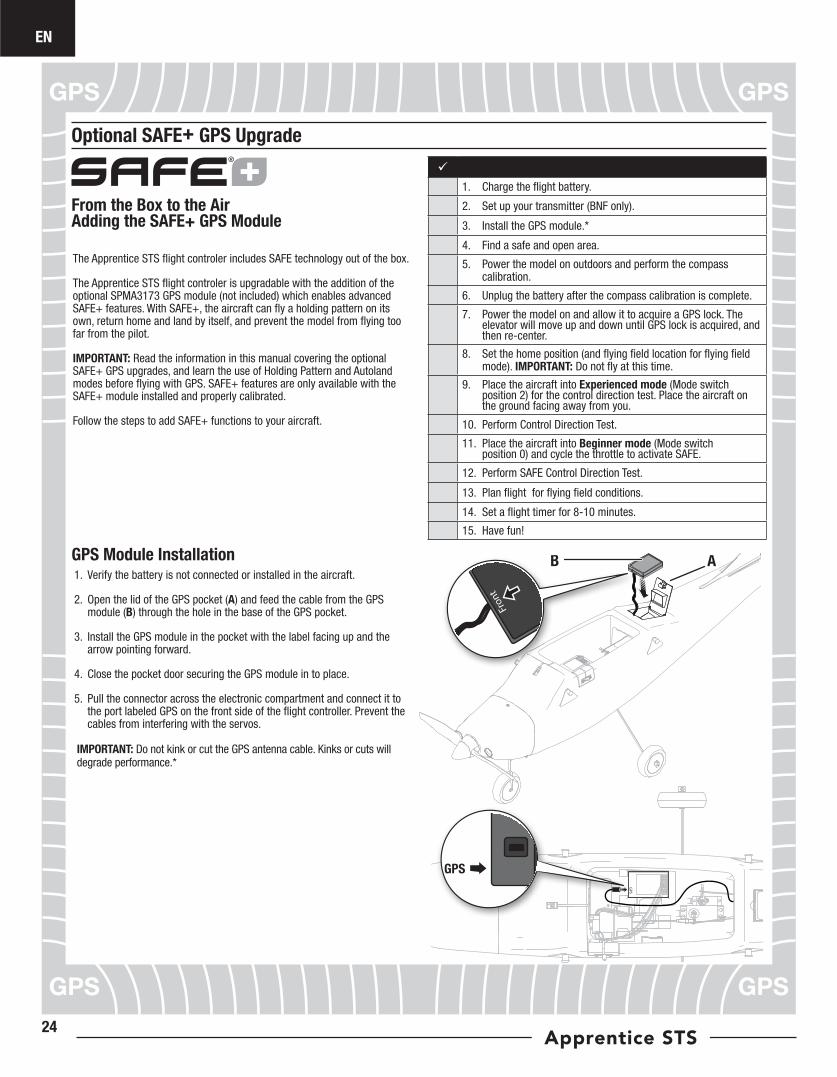
The Apprentice STS flight controler includes SAFE technology out of the box.
The Apprentice STS flight controler is upgradable with the addition of the optional SPMA3173 GPS module (not included) which enables advanced SAFE+ features. With SAFE+, the aircraft can fly a holding pattern on its own, return home and land by itself, and prevent the model from flying too far from the pilot.
IMPORTANT: Read the information in this manual covering the optional SAFE+ GPS upgrades, and learn the use of Holding Pattern and Autoland modes before flying with GPS. SAFE+ features are only available with the SAFE+ module installed and properly calibrated.
Follow the steps to add SAFE+ functions to your aircraft.
From the Box to the Air Adding the SAFE+ GPS Module
1. Charge the flight battery.
2. Set up your transmitter (BNF only).
3. Install the GPS module.*
4. Find a safe and open area.
5. Power the model on outdoors and perform the compass calibration.
6. Unplug the battery after the compass calibration is complete.
7. Power the model on and allow it to acquire a GPS lock. The elevator will move up and down until GPS lock is acquired, and then re-center.
8. Set the home position (and flying field location for flying field mode). IMPORTANT: Do not fly at this time.
9. Place the aircraft into Experienced mode (Mode switch position 2) for the control direction test. Place the aircraft on the ground facing away from you.
10. Perform Control Direction Test.
11. Place the aircraft into Beginner mode (Mode switch position 0) and cycle the throttle to activate SAFE.
12. Perform SAFE Control Direction Test.
13. Plan flight for flying field conditions.
14. Set a flight timer for 8-10 minutes.
15. Have fun!
GPS Module Installation1. Verify the battery is not connected or installed in the aircraft.
2. Open the lid of the GPS pocket (A) and feed the cable from the GPS module (B) through the hole in the base of the GPS pocket.
3. Install the GPS module in the pocket with the label facing up and the arrow pointing forward.
4. Close the pocket door securing the GPS module in to place.
5. Pull the connector across the electronic compartment and connect it to the port labeled GPS on the front side of the flight controller. Prevent the cables from interfering with the servos.
IMPORTANT: Do not kink or cut the GPS antenna cable. Kinks or cuts will degrade performance.*
GPS
GPS
Front
AB
EN
25
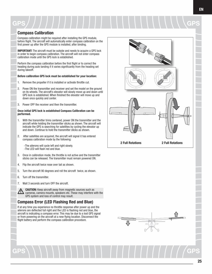
Compass CalibrationCompass calibration might be required after installing the GPS module, before flight. The aircraft will automatically enter compass calibration on the first power up after the GPS module is installed, after binding.
IMPORTANT: The aircraft must be outside and needs to acquire a GPS lock in order to begin compass calibration. The aircraft will not enter compass calibration mode until the GPS lock is established.
Perform the compass calibration before the first flight or to correct the heading during auto landing if it varies significantly from the heading set during takeoff.
Before calibration GPS lock must be established for your location:
1. Remove the propeller if it is installed or activate throttle cut.
2. Powe ON the transmitter and receiver and set the model on the ground on its wheels. The aircraft’s elevator will slowly move up and down until GPS lock is established. When finished the elevator will move up and down once quickly and center.
3. Power OFF the receiver and then the transmitter.
Once initial GPS lock is established Compass Calibration can be performed.
1. With the transmitter trims centered, power ON the transmitter and the aircraft while holding the transmitter sticks as shown. The aircraft will indicate the GPS is searching for satellites by cycling the elevator up and down. Continue to hold the transmitter sticks as shown.
2. After satellites are acquired, the aircraft will signal it has entered compass calibration mode by the following:
-The ailerons will cycle left and right slowly. -The LED will flash red and blue.
3. Once in calibration mode, the throttle is not active and the transmitter sticks can be released. The transmitter must remain powered ON.
4. Flip the aircraft twice nose over tail as shown.
5. Turn the aircraft 90 degrees and roll the aircraft twice, as shown.
6. Turn off the transmitter.
7. Wait 3 seconds and turn OFF the aircraft.
CAUTION: Keep aircraft away from magnetic sources such as cameras, camera mounts, speakers etc. These may interfere with the GPS system and loss of control may result.
Compass Error (LED Flashing Red and Blue)If at any time you experience no throttle response after power up and the ailerons are deflected full right and the LED is flashing red and blue, the aircraft is indicating a compass error. This may be due to a lost GPS signal or from powering on the aircraft at a new flying location. Disconnect the flight battery and perform the compass calibration procedure.
2 Full Rotations2 Full Rotations
EN
Apprentice STS26
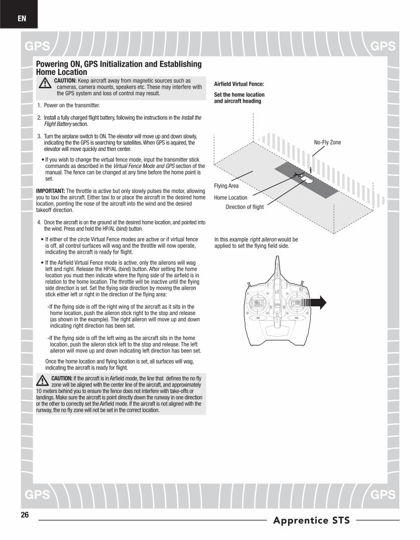
Powering ON, GPS Initialization and Establishing Home Location
CAUTION: Keep aircraft away from magnetic sources such as cameras, camera mounts, speakers etc. These may interfere with the GPS system and loss of control may result.
1. Power on the transmitter.
2. Install a fully charged flight battery, following the instructions in the Install the Flight Battery section.
3. Turn the airplane switch to ON. The elevator will move up and down slowly, indicating the the GPS is searching for satellites. When GPS is aquired, the elevator will move quickly and then center.
• If you wish to change the virtual fence mode, input the transmitter stick commands as described in the Virtual Fence Mode and GPS section of the manual. The fence can be changed at any time before the home point is set.
IMPORTANT: The throttle is active but only slowly pulses the motor, allowing you to taxi the aircraft. Either taxi to or place the aircraft in the desired home location, pointing the nose of the aircraft into the wind and the desired takeoff direction.
4. Once the aircraft is on the ground at the desired home location, and pointed into the wind. Press and hold the HP/AL (bind) button.
• If either of the circle Virtual Fence modes are active or if virtual fence is off, all control surfaces will wag and the throttle will now operate, indicating the aircraft is ready for flight.
• If the Airfield Virtual Fence mode is active, only the ailerons will wag left and right. Release the HP/AL (bind) button. After setting the home location you must then indicate where the flying side of the airfield is in relation to the home location. The throttle will be inactive until the flying side direction is set. Set the flying side direction by moving the aileron stick either left or right in the direction of the flying area:
-If the flying side is off the right wing of the aircraft as it sits in the home location, push the aileron stick right to the stop and release (as shown in the example). The right aileron will move up and down indicating right direction has been set.
-If the flying side is off the left wing as the aircraft sits in the home location, push the aileron stick left to the stop and release. The left aileron will move up and down indicating left direction has been set.
Once the home location and flying location is set, all surfaces will wag, indicating the aircraft is ready for flight.
CAUTION: If the aircraft is in Airfield mode, the line that defines the no fly zone will be aligned with the center line of the aircraft, and approximately
10 meters behind you to ensure the fence does not interfere with take-offs or landings. Make sure the aircraft is point directly down the runway in one direction or the other to correctly set the Airfield mode. If the aircraft is not aligned with the runway, the no fly zone will not be set in the correct location.
Home Location
No-Fly Zone
In this example right aileron would be applied to set the flying field side.
Flying Area
Direction of flight
Airfield Virtual Fence:
Set the home location and aircraft heading
EN
27
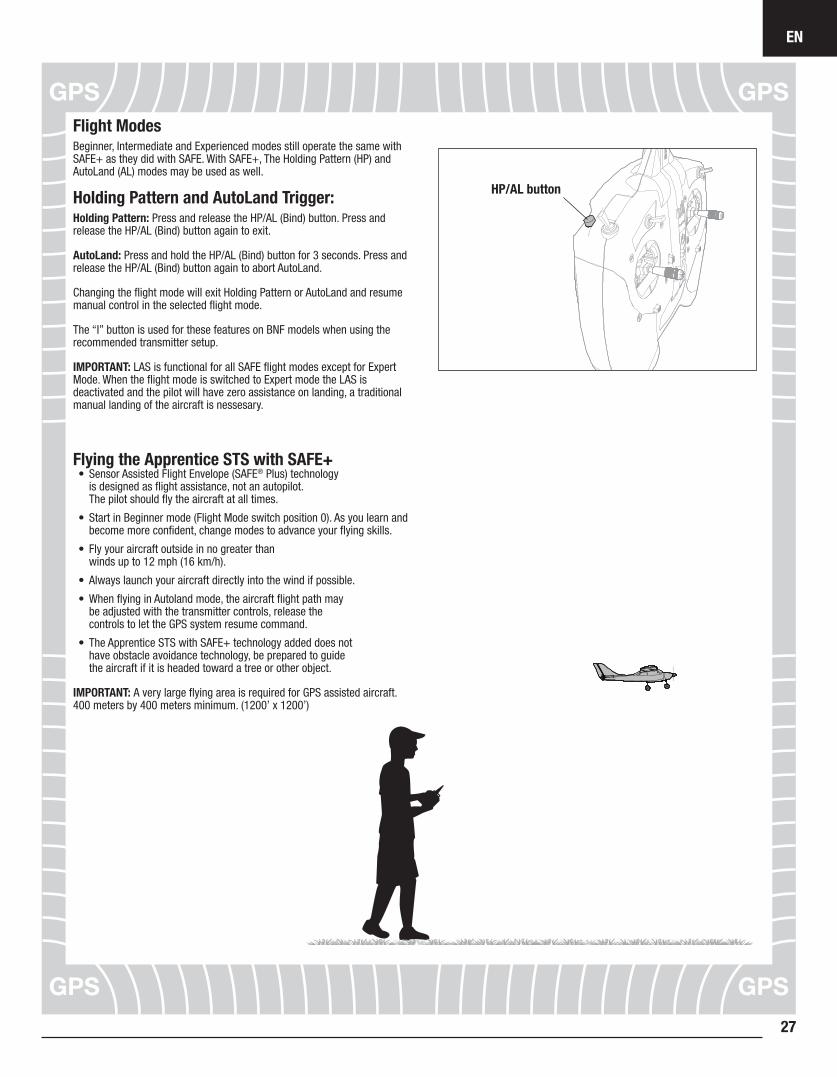
Flight ModesBeginner, Intermediate and Experienced modes still operate the same with SAFE+ as they did with SAFE. With SAFE+, The Holding Pattern (HP) and AutoLand (AL) modes may be used as well.
Holding Pattern and AutoLand Trigger:Holding Pattern: Press and release the HP/AL (Bind) button. Press and release the HP/AL (Bind) button again to exit.
AutoLand: Press and hold the HP/AL (Bind) button for 3 seconds. Press and release the HP/AL (Bind) button again to abort AutoLand.
Changing the flight mode will exit Holding Pattern or AutoLand and resume manual control in the selected flight mode.
The “I” button is used for these features on BNF models when using the recommended transmitter setup.
IMPORTANT: LAS is functional for all SAFE flight modes except for Expert Mode. When the flight mode is switched to Expert mode the LAS is deactivated and the pilot will have zero assistance on landing, a traditional manual landing of the aircraft is nessesary.
Flying the Apprentice STS with SAFE+• Sensor Assisted Flight Envelope (SAFE® Plus) technology
is designed as flight assistance, not an autopilot. The pilot should fly the aircraft at all times.
• Start in Beginner mode (Flight Mode switch position 0). As you learn and become more confident, change modes to advance your flying skills.
• Fly your aircraft outside in no greater than winds up to 12 mph (16 km/h).
• Always launch your aircraft directly into the wind if possible.
• When flying in Autoland mode, the aircraft flight path may be adjusted with the transmitter controls, release the controls to let the GPS system resume command.
• The Apprentice STS with SAFE+ technology added does not have obstacle avoidance technology, be prepared to guide the aircraft if it is headed toward a tree or other object.
IMPORTANT: A very large flying area is required for GPS assisted aircraft. 400 meters by 400 meters minimum. (1200’ x 1200’)
HP/AL button
EN
Apprentice STS28
Small (Default)
Home Location
Large
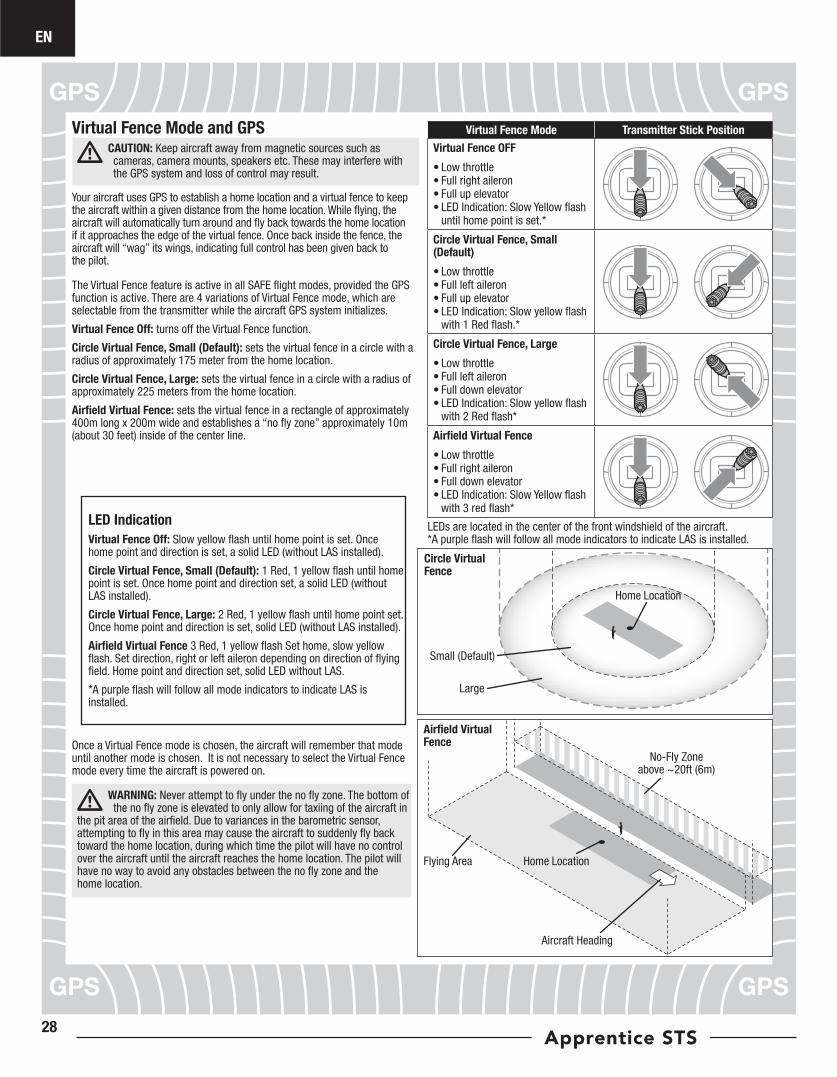
Virtual Fence Mode Transmitter Stick Position
Virtual Fence OFF
• Low throttle• Full right aileron• Full up elevator• LED Indication: Slow Yellow flash
until home point is set.*
Circle Virtual Fence, Small (Default)
• Low throttle• Full left aileron• Full up elevator• LED Indication: Slow yellow flash
with 1 Red flash.*
Circle Virtual Fence, Large
• Low throttle• Full left aileron• Full down elevator• LED Indication: Slow yellow flash
with 2 Red flash*
Airfield Virtual Fence
• Low throttle• Full right aileron• Full down elevator• LED Indication: Slow Yellow flash
with 3 red flash*
Circle Virtual Fence
Home Location
Aircraft Heading
No-Fly Zone above ~20ft (6m)
Flying Area
Airfield Virtual Fence
LEDs are located in the center of the front windshield of the aircraft. *A purple flash will follow all mode indicators to indicate LAS is installed.
Virtual Fence Mode and GPSCAUTION: Keep aircraft away from magnetic sources such as cameras, camera mounts, speakers etc. These may interfere with the GPS system and loss of control may result.
Your aircraft uses GPS to establish a home location and a virtual fence to keep the aircraft within a given distance from the home location. While flying, the aircraft will automatically turn around and fly back towards the home location if it approaches the edge of the virtual fence. Once back inside the fence, the aircraft will “wag” its wings, indicating full control has been given back to the pilot.
The Virtual Fence feature is active in all SAFE flight modes, provided the GPS function is active. There are 4 variations of Virtual Fence mode, which are selectable from the transmitter while the aircraft GPS system initializes.
Virtual Fence Off: turns off the Virtual Fence function.
Circle Virtual Fence, Small (Default): sets the virtual fence in a circle with a radius of approximately 175 meter from the home location.
Circle Virtual Fence, Large: sets the virtual fence in a circle with a radius of approximately 225 meters from the home location.
Airfield Virtual Fence: sets the virtual fence in a rectangle of approximately 400m long x 200m wide and establishes a “no fly zone” approximately 10m (about 30 feet) inside of the center line.
Once a Virtual Fence mode is chosen, the aircraft will remember that mode until another mode is chosen. It is not necessary to select the Virtual Fence mode every time the aircraft is powered on.
WARNING: Never attempt to fly under the no fly zone. The bottom of the no fly zone is elevated to only allow for taxiing of the aircraft in
the pit area of the airfield. Due to variances in the barometric sensor, attempting to fly in this area may cause the aircraft to suddenly fly back toward the home location, during which time the pilot will have no control over the aircraft until the aircraft reaches the home location. The pilot will have no way to avoid any obstacles between the no fly zone and the home location.
LED Indication
Virtual Fence Off: Slow yellow flash until home point is set. Once home point and direction is set, a solid LED (without LAS installed).
Circle Virtual Fence, Small (Default): 1 Red, 1 yellow flash until home point is set. Once home point and direction set, a solid LED (without LAS installed).
Circle Virtual Fence, Large: 2 Red, 1 yellow flash until home point set. Once home point and direction is set, solid LED (without LAS installed).
Airfield Virtual Fence 3 Red, 1 yellow flash Set home, slow yellow flash. Set direction, right or left aileron depending on direction of flying field. Home point and direction set, solid LED without LAS.
*A purple flash will follow all mode indicators to indicate LAS is installed.
EN
29
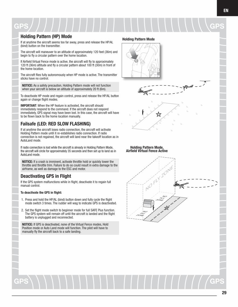
Holding Pattern Mode
Holding Pattern Mode, Airfield Virtual Fence Active
Holding Pattern (HP) ModeIf at anytime the aircraft seems too far away, press and release the HP/AL (bind) button on the transmitter.
The aircraft will maneuver to an altitude of approximately 120 feet (36m) and begin to fly a circular pattern over the home location.
If Airfield Virtual Fence mode is active, the aircraft will fly to approximately 120 ft (36m) altitude and fly a circular pattern about 100 ft (30m) in front of the home location.
The aircraft flies fully autonomously when HP mode is active. The transmitter sticks have no control.
NOTICE: As a safety precaution, Holding Pattern mode will not function when your aircraft is below an altitude of approximately 20 ft (6m).
To deactivate HP mode and regain control, press and release the HP/AL button again or change flight modes.
IMPORTANT: When the HP feature is activated, the aircraft should immediately respond to the command. If the aircraft does not respond immediately, GPS signal may have been lost. In this case, the aircraft will have to be flown back to the home location manually.
Failsafe (LED: RED SLOW FLASHING)If at anytime the aircraft loses radio connection, the aircraft will activate Holding Pattern mode until it re-establishes radio connection. If radio connection is not regained, the aircraft will land near the takeoff location as in AutoLand mode.
If radio connection is lost while the aircraft is already in Holding Pattern Mode, the aircraft will circle for approximately 35 seconds and then set up to land as in AutoLand mode.
NOTICE: If a crash is imminent, activate throttle hold or quickly lower the throttle and throttle trim. Failure to do so could result in extra damage to the airframe, as well as damage to the ESC and motor.
Deactivating GPS in FlightIf the GPS system malfunctions while in flight, deactivate it to regain full manual control.
To deactivate the GPS in flight:
1. Press and hold the HP/AL (bind) button down and fully cycle the flight mode switch 3 times. The rudder will wag to indicate GPS is deactivated.
2. Set the flight mode switch to beginner mode for full SAFE Plus function. The GPS system will remain off until the aircraft is landed and the flight battery is unplugged and reconnected.
NOTICE: If GPS is deactivated, none of the Virtual Fence modes, Hold Position mode or Auto Land mode will function. The pilot will have to manually fly the aircraft back to a safe landing.
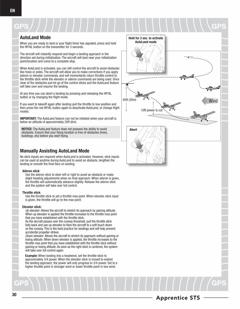
EN
Apprentice STS30
Manually Assisting AutoLand ModeNo stick inputs are required when AutoLand is activated. However, stick inputs can be used at anytime during AutoLand to avoid an obstacle, lengthen the landing or smooth the final flare on landing.
Aileron stick: Use the aileron stick to steer left or right to avoid an obstacle or make slight heading adjustments when on final approach. When aileron is given, the throttle will automatically advance slightly. Release the aileron stick and the system will take over full control.
Throttle stick: Use the throttle stick to set a throttle max point. When elevator stick input is given, the throttle will go to the max point.
Elevator stick: Up elevator: Allows the aircraft to stretch its approach by gaining altitude. When up elevator is applied the throttle increases to the throttle max point that you have established with the throttle stick. As the aircraft passes over the runway threshold, pull the throttle stick fully back and use up elevator to flare the aircraft to a soft touch down on the runway. This is the best practice for landings and will help prevent accidental propeller strikes. Down elevator : Allows the aircraft to stretch its approach without gaining or losing altitude. When down elevator is applied, the throttle increases to the throttle max point that you have established with the throttle stick without gaining or losing altitude. As soon as the right stick is centered, the system will take over full control again.
Example: When landing into a headwind, set the throttle stick to approximately 3/4 power. When the elevator stick is moved to extend the landing approach, the power will only progress to 3/4 power. Set to a higher throttle point in stronger wind or lower throttle point in low wind.
65ft (20m)
10ft power is cut
Wind
Hold for 3 sec. to activate AutoLand mode
Abort
AutoLand ModeWhen you are ready to land or your flight timer has signaled, press and hold the HP/AL button on the transmitter for 3 seconds.
The aircraft will instantly respond and begin a landing approach in the direction set during initialization. The aircraft will land near your initialization point/location and come to a complete stop.
When AutoLand is activated, you can still control the aircraft to avoid obstacles like trees or poles. The aircraft will allow you to make corrections if you apply aileron or elevator commands, and will momentarily return throttle control to the throttle stick while the elevator or aileron commands are being used. Once clear of the obstacles just let go of the control sticks and the AutoLand feature will take over and resume the landing.
At any time you can abort a landing by pressing and releasing the HP/AL button or by changing the flight mode.
If you want to takeoff again after landing pull the throttle to low position and then press the red HP/AL button again to deactivate AutoLand, or change flight modes.
IMPORTANT: The AutoLand feature can not be initiated when your aircraft is below an altitude of approximately 20ft (6m).
NOTICE: The AutoLand feature does not possess the ability to avoid obstacles. Ensure that your flying location is free of obstacles (trees, buildings, etc) before you start flying.
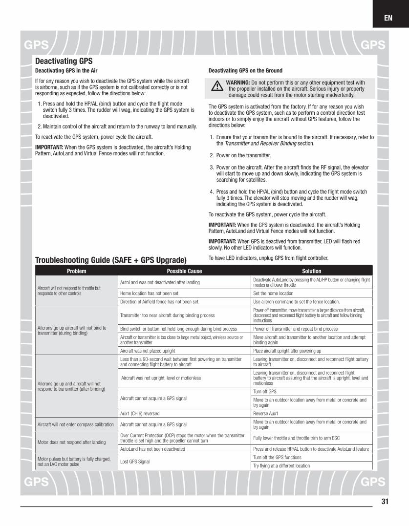
EN
31
Deactivating GPS in the Air
If for any reason you wish to deactivate the GPS system while the aircraft is airborne, such as if the GPS system is not calibrated correctly or is not responding as expected, follow the directions below:
1. Press and hold the HP/AL (bind) button and cycle the flight mode switch fully 3 times. The rudder will wag, indicating the GPS system is deactivated.
2. Maintain control of the aircraft and return to the runway to land manually.
To reactivate the GPS system, power cycle the aircraft.
IMPORTANT: When the GPS system is deactivated, the aircraft’s Holding Pattern, AutoLand and Virtual Fence modes will not function.
Deactivating GPS on the Ground
WARNING: Do not perform this or any other equipment test with the propeller installed on the aircraft. Serious injury or property damage could result from the motor starting inadvertently.
The GPS system is activated from the factory. If for any reason you wish to deactivate the GPS system, such as to perform a control direction test indoors or to simply enjoy the aircraft without GPS features, follow the directions below:
1. Ensure that your transmitter is bound to the aircraft. If necessary, refer to the Transmitter and Receiver Binding section.
2. Power on the transmitter.
3. Power on the aircraft. After the aircraft finds the RF signal, the elevator will start to move up and down slowly, indicating the GPS system is searching for satellites.
4. Press and hold the HP/AL (bind) button and cycle the flight mode switch fully 3 times. The elevator will stop moving and the rudder will wag, indicating the GPS system is deactivated.
To reactivate the GPS system, power cycle the aircraft.
IMPORTANT: When the GPS system is deactivated, the aircraft’s Holding Pattern, AutoLand and Virtual Fence modes will not function.
IMPORTANT: When GPS is deactived from transmitter, LED will flash red slowly. No other LED indicators will function.
To have LED indicators, unplug GPS from flight controller.
Deactivating GPS
Troubleshooting Guide (SAFE + GPS Upgrade)Problem Possible Cause Solution
Aircraft will not respond to throttle but responds to other controls
AutoLand was not deactivated after landing Deactivate AutoLand by pressing the AL/HP button or changing flight modes and lower throttle
Home location has not been set Set the home location
Direction of Airfield fence has not been set. Use aileron command to set the fence location.
Ailerons go up aircraft will not bind to transmitter (during binding)
Transmitter too near aircraft during binding processPower off transmitter, move transmitter a larger distance from aircraft, disconnect and reconnect flight battery to aircraft and follow binding instructions
Bind switch or button not held long enough during bind process Power off transmitter and repeat bind process
Aircraft or transmitter is too close to large metal object, wireless source or another transmitter
Move aircraft and transmitter to another location and attempt binding again
Aircraft was not placed upright Place aircraft upright after powering up
Ailerons go up and aircraft will not respond to transmitter (after binding)
Less than a 90-second wait between first powering on transmitter and connecting flight battery to aircraft
Leaving transmitter on, disconnect and reconnect flight battery to aircraft
Aircraft was not upright, level or motionlessLeaving transmitter on, disconnect and reconnect flight battery to aircraft assuring that the aircraft is upright, level and motionless
Aircraft cannot acquire a GPS signalTurn off GPS
Move to an outdoor location away from metal or concrete and try again
Aux1 (CH 6) reversed Reverse Aux1
Aircraft will not enter compass calibration Aircraft cannot acquire a GPS signal Move to an outdoor location away from metal or concrete and try again
Motor does not respond after landingOver Current Protection (OCP) stops the motor when the transmitter throttle is set high and the propeller cannot turn Fully lower throttle and throttle trim to arm ESC
AutoLand has not been deactivated Press and release HP/AL button to deactivate AutoLand feature
Motor pulses but battery is fully charged, not an LVC motor pulse Lost GPS Signal
Turn off the GPS functions
Try flying at a different location
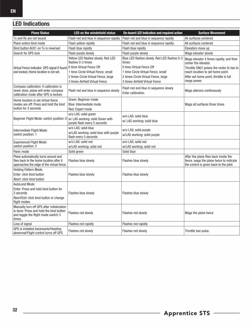
EN
Apprentice STS32
Plane Status LED on the windshield status On-board LED Indication and required action Surface Movement
Tx and Rx are not bound Flash red and blue in sequence rapidly Flash red and blue in sequence rapidly All surfaces centeredPlane enters bind mode Flash yellow rapidly Flash red and blue in sequence rapidly All surfaces centeredBind button AUX1 on Tx is reversed Flash blue rapidly Flash blue rapidly Elevators move upSearch for GPS lock Flash purple slowly Flash purple slowly Wags elevator slowly
Virtual Fence indicator; GPS signal if found and locked, Home location is not set.
Yellow LED flashes slowly. Red LED flashes 0-3 times: 0 time-Virtual Fence Off1 time-Circle Virtual Fence, small2 times-Circle Virtual Fence, large3 times-Airfield Virtual Fence
Blue LED flashes slowly. Red LED flashes 0-3 times: 0 time-Virtual Fence Off1 time-Circle Virtual Fence, small2 times-Circle Virtual Fence, large3 times-Airfield Virtual Fence
Wags elevator 4 times rapidly, and then center the elevator. Throttle ONLY pulses the motor to taxi to reach location to set home point.After set home point, throttle is full range power.
Compass calibration: if calibration is never done, plane will enter compass calibration mode after GPS is locked.
Flash red and blue in sequence slowlyFlash red and blue in sequence slowlyEnter calibration.
Wags ailerons continuously
Home location is set virtual fence modes are off: Press and hold the bind button for 3 seconds
Green: Beginner modeBlue: Intermediate modeRed: Expert mode
Wags all surfaces three times
Beginner Flight Mode: switch position: 0w/o LAS: solid greenw/ LAS working: solid Green with purple flash every 5 seconds
w/o LAS: solid bluew/ LAS working: solid blue
Intermediate Flight Mode: switch position: 1
w/o LAS: solid bluew/LAS working: solid blue with purple flash every 5 seconds
w/o LAS: solid purple w/LAS working: solid purple
Experienced Flight Mode: switch position: 2
w/o LAS: solid redw/LAS working: solid red
w/o LAS: solid redw/LAS working: solid red
Panic mode Solid green Solid bluePlane automatically turns around and flies back to the home location after it approaches the edge of the virtual fence.
Flashes blue slowly Flashes blue slowly After the plane flies back inside the fence, wags the plane twice to indicate the control is given back to the pilot.
Holding Pattern Mode: Enter: click bind buttonAbort: click bind button
Flashes blue slowly Flashes blue slowly
AutoLand Mode:Enter: Press and hold bind button for 3 secondsAbort/Exit: click bind button or change flight modes
Flashes blue slowly Flashes blue slowly
Manually turn off GPS after initialization is done: Press and hold the bind button and toggle the flight mode switch 3 times.
Flashes red slowly Flashes red slowly Wags the plane twice
Loss of signal Flashes red rapidly Flashes red rapidlyGPS is installed backwards/Heading abnormal/Flight control turns off GPS Flashes red slowly Flashes red slowly Throttle taxi pulse.
LED Indications
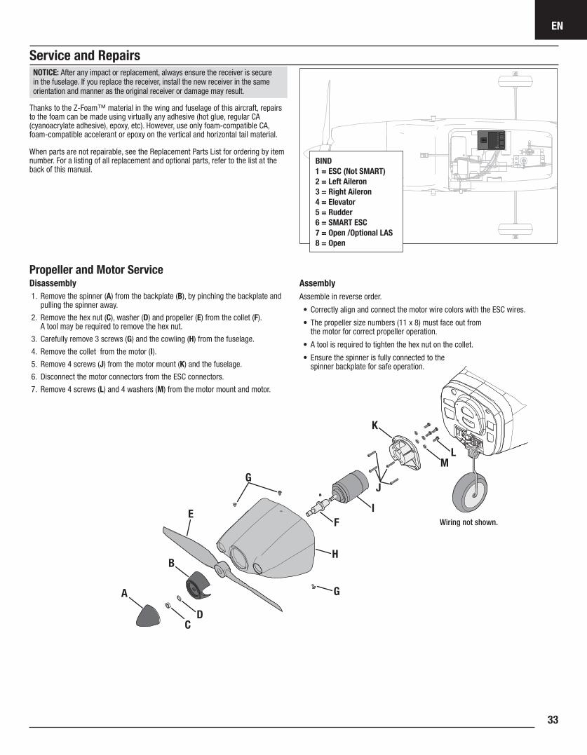
EN
33
Disassembly1. Remove the spinner (A) from the backplate (B), by pinching the backplate and
pulling the spinner away.
2. Remove the hex nut (C), washer (D) and propeller (E) from the collet (F). A tool may be required to remove the hex nut.
3. Carefully remove 3 screws (G) and the cowling (H) from the fuselage.
4. Remove the collet from the motor (I).
5. Remove 4 screws (J) from the motor mount (K) and the fuselage.
6. Disconnect the motor connectors from the ESC connectors.
7. Remove 4 screws (L) and 4 washers (M) from the motor mount and motor.
AssemblyAssemble in reverse order.
• Correctly align and connect the motor wire colors with the ESC wires.
• The propeller size numbers (11 x 8) must face out from the motor for correct propeller operation.
• A tool is required to tighten the hex nut on the collet.
• Ensure the spinner is fully connected to the spinner backplate for safe operation.
A
B
CD
E F
I
J
K
L M
G
G
H
Wiring not shown.
Service and Repairs
Propeller and Motor Service
NOTICE: After any impact or replacement, always ensure the receiver is secure in the fuselage. If you replace the receiver, install the new receiver in the same orientation and manner as the original receiver or damage may result.
Thanks to the Z-Foam™ material in the wing and fuselage of this aircraft, repairs to the foam can be made using virtually any adhesive (hot glue, regular CA (cyanoacrylate adhesive), epoxy, etc). However, use only foam-compatible CA, foam-compatible accelerant or epoxy on the vertical and horizontal tail material.
When parts are not repairable, see the Replacement Parts List for ordering by item number. For a listing of all replacement and optional parts, refer to the list at the back of this manual.
BIND1 = ESC (Not SMART) 2 = Left Aileron3 = Right Aileron4 = Elevator5 = Rudder6 = SMART ESC7 = Open /Optional LAS8 = Open
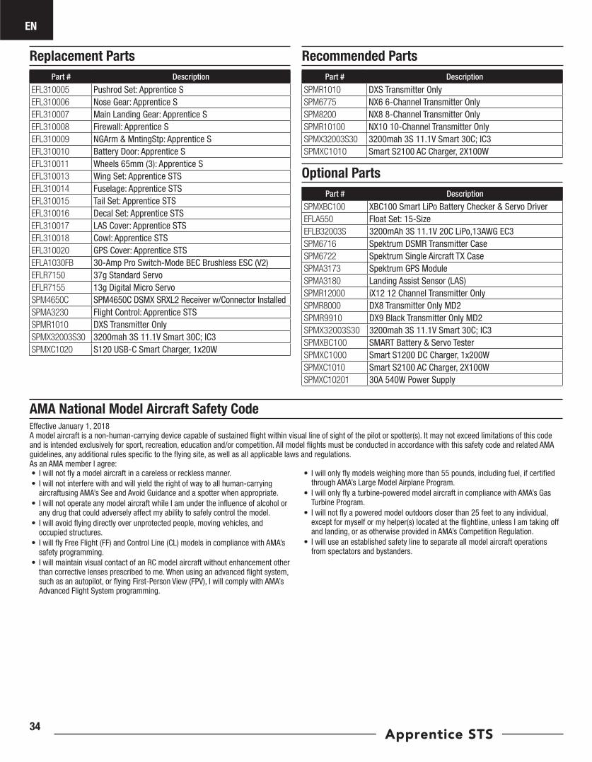
EN
Apprentice STS34
AMA National Model Aircraft Safety Code
Replacement Parts Recommended PartsPart # Description
EFL310005 Pushrod Set: Apprentice SEFL310006 Nose Gear: Apprentice SEFL310007 Main Landing Gear: Apprentice SEFL310008 Firewall: Apprentice SEFL310009 NGArm & MntingStp: Apprentice SEFL310010 Battery Door: Apprentice SEFL310011 Wheels 65mm (3): Apprentice SEFL310013 Wing Set: Apprentice STSEFL310014 Fuselage: Apprentice STSEFL310015 Tail Set: Apprentice STSEFL310016 Decal Set: Apprentice STSEFL310017 LAS Cover: Apprentice STSEFL310018 Cowl: Apprentice STSEFL310020 GPS Cover: Apprentice STSEFLA1030FB 30-Amp Pro Switch-Mode BEC Brushless ESC (V2)EFLR7150 37g Standard ServoEFLR7155 13g Digital Micro ServoSPM4650C SPM4650C DSMX SRXL2 Receiver w/Connector InstalledSPMA3230 Flight Control: Apprentice STSSPMR1010 DXS Transmitter OnlySPMX32003S30 3200mah 3S 11.1V Smart 30C; IC3SPMXC1020 S120 USB-C Smart Charger, 1x20W
Part # Description
SPMR1010 DXS Transmitter OnlySPM6775 NX6 6-Channel Transmitter OnlySPM8200 NX8 8-Channel Transmitter OnlySPMR10100 NX10 10-Channel Transmitter OnlySPMX32003S30 3200mah 3S 11.1V Smart 30C; IC3SPMXC1010 Smart S2100 AC Charger, 2X100W
Optional PartsPart # Description
SPMXBC100 XBC100 Smart LiPo Battery Checker & Servo DriverEFLA550 Float Set: 15-SizeEFLB32003S 3200mAh 3S 11.1V 20C LiPo,13AWG EC3SPM6716 Spektrum DSMR Transmitter CaseSPM6722 Spektrum Single Aircraft TX CaseSPMA3173 Spektrum GPS ModuleSPMA3180 Landing Assist Sensor (LAS)SPMR12000 iX12 12 Channel Transmitter OnlySPMR8000 DX8 Transmitter Only MD2SPMR9910 DX9 Black Transmitter Only MD2SPMX32003S30 3200mah 3S 11.1V Smart 30C; IC3SPMXBC100 SMART Battery & Servo TesterSPMXC1000 Smart S1200 DC Charger, 1x200WSPMXC1010 Smart S2100 AC Charger, 2X100WSPMXC10201 30A 540W Power Supply
Effective January 1, 2018A model aircraft is a non-human-carrying device capable of sustained flight within visual line of sight of the pilot or spotter(s). It may not exceed limitations of this code and is intended exclusively for sport, recreation, education and/or competition. All model flights must be conducted in accordance with this safety code and related AMA guidelines, any additional rules specific to the flying site, as well as all applicable laws and regulations.As an AMA member I agree:• I will not fly a model aircraft in a careless or reckless manner.• I will not interfere with and will yield the right of way to all human-carrying
aircraftusing AMA’s See and Avoid Guidance and a spotter when appropriate.• I will not operate any model aircraft while I am under the influence of alcohol or
any drug that could adversely affect my ability to safely control the model.• I will avoid flying directly over unprotected people, moving vehicles, and
occupied structures.• I will fly Free Flight (FF) and Control Line (CL) models in compliance with AMA’s
safety programming.• I will maintain visual contact of an RC model aircraft without enhancement other
than corrective lenses prescribed to me. When using an advanced flight system, such as an autopilot, or flying First-Person View (FPV), I will comply with AMA’s Advanced Flight System programming.
• I will only fly models weighing more than 55 pounds, including fuel, if certified through AMA’s Large Model Airplane Program.
• I will only fly a turbine-powered model aircraft in compliance with AMA’s Gas Turbine Program.
• I will not fly a powered model outdoors closer than 25 feet to any individual, except for myself or my helper(s) located at the flightline, unless I am taking off and landing, or as otherwise provided in AMA’s Competition Regulation.
• I will use an established safety line to separate all model aircraft operations from spectators and bystanders.
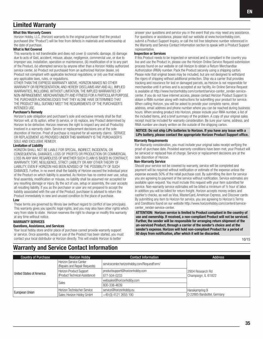
EN
35
Limited Warranty
Warranty and Service Contact Information
What this Warranty CoversHorizon Hobby, LLC, (Horizon) warrants to the original purchaser that the product purchased (the “Product”) will be free from defects in materials and workmanship at the date of purchase.What is Not CoveredThis warranty is not transferable and does not cover (i) cosmetic damage, (ii) damage due to acts of God, accident, misuse, abuse, negligence, commercial use, or due to improper use, installation, operation or maintenance, (iii) modification of or to any part of the Product, (iv) attempted service by anyone other than a Horizon Hobby authorized service center, (v) Product not purchased from an authorized Horizon dealer, (vi) Product not compliant with applicable technical regulations, or (vii) use that violates any applicable laws, rules, or regulations. OTHER THAN THE EXPRESS WARRANTY ABOVE, HORIZON MAKES NO OTHER WARRANTY OR REPRESENTATION, AND HEREBY DISCLAIMS ANY AND ALL IMPLIED WARRANTIES, INCLUDING, WITHOUT LIMITATION, THE IMPLIED WARRANTIES OF NON-INFRINGEMENT, MERCHANTABILITY AND FITNESS FOR A PARTICULAR PURPOSE. THE PURCHASER ACKNOWLEDGES THAT THEY ALONE HAVE DETERMINED THAT THE PRODUCT WILL SUITABLY MEET THE REQUIREMENTS OF THE PURCHASER’S INTENDED USE. Purchaser’s RemedyHorizon’s sole obligation and purchaser’s sole and exclusive remedy shall be that Horizon will, at its option, either (i) service, or (ii) replace, any Product determined by Horizon to be defective. Horizon reserves the right to inspect any and all Product(s) involved in a warranty claim. Service or replacement decisions are at the sole discretion of Horizon. Proof of purchase is required for all warranty claims. SERVICE OR REPLACEMENT AS PROVIDED UNDER THIS WARRANTY IS THE PURCHASER’S SOLE AND EXCLUSIVE REMEDY. Limitation of LiabilityHORIZON SHALL NOT BE LIABLE FOR SPECIAL, INDIRECT, INCIDENTAL OR CONSEQUENTIAL DAMAGES, LOSS OF PROFITS OR PRODUCTION OR COMMERCIAL LOSS IN ANY WAY, REGARDLESS OF WHETHER SUCH CLAIM IS BASED IN CONTRACT, WARRANTY, TORT, NEGLIGENCE, STRICT LIABILITY OR ANY OTHER THEORY OF LIABILITY, EVEN IF HORIZON HAS BEEN ADVISED OF THE POSSIBILITY OF SUCH DAMAGES. Further, in no event shall the liability of Horizon exceed the individual price of the Product on which liability is asserted. As Horizon has no control over use, setup, final assembly, modification or misuse, no liability shall be assumed nor accepted for any resulting damage or injury. By the act of use, setup or assembly, the user accepts all resulting liability. If you as the purchaser or user are not prepared to accept the liability associated with the use of the Product, purchaser is advised to return the Product immediately in new and unused condition to the place of purchase.LawThese terms are governed by Illinois law (without regard to conflict of law principals). This warranty gives you specific legal rights, and you may also have other rights which vary from state to state. Horizon reserves the right to change or modify this warranty at any time without notice.WARRANTY SERVICESQuestions, Assistance, and ServicesYour local hobby store and/or place of purchase cannot provide warranty support or service. Once assembly, setup or use of the Product has been started, you must contact your local distributor or Horizon directly. This will enable Horizon to better
answer your questions and service you in the event that you may need any assistance. For questions or assistance, please visit our website at www.horizonhobby.com, submit a Product Support Inquiry, or call the toll free telephone number referenced in the Warranty and Service Contact Information section to speak with a Product Support representative. Inspection or ServicesIf this Product needs to be inspected or serviced and is compliant in the country you live and use the Product in, please use the Horizon Online Service Request submission process found on our website or call Horizon to obtain a Return Merchandise Authorization (RMA) number. Pack the Product securely using a shipping carton. Please note that original boxes may be included, but are not designed to withstand the rigors of shipping without additional protection. Ship via a carrier that provides tracking and insurance for lost or damaged parcels, as Horizon is not responsible for merchandise until it arrives and is accepted at our facility. An Online Service Request is available at http://www.horizonhobby.com/content/service-center_render-service-center. If you do not have internet access, please contact Horizon Product Support to obtain a RMA number along with instructions for submitting your product for service. When calling Horizon, you will be asked to provide your complete name, street address, email address and phone number where you can be reached during business hours. When sending product into Horizon, please include your RMA number, a list of the included items, and a brief summary of the problem. A copy of your original sales receipt must be included for warranty consideration. Be sure your name, address, and RMA number are clearly written on the outside of the shipping carton.
NOTICE: Do not ship LiPo batteries to Horizon. If you have any issue with a LiPo battery, please contact the appropriate Horizon Product Support office.
Warranty Requirements For Warranty consideration, you must include your original sales receipt verifying the proof-of-purchase date. Provided warranty conditions have been met, your Product will be serviced or replaced free of charge. Service or replacement decisions are at the sole discretion of Horizon.Non-Warranty ServiceShould your service not be covered by warranty, service will be completed and payment will be required without notification or estimate of the expense unless the expense exceeds 50% of the retail purchase cost. By submitting the item for service you are agreeing to payment of the service without notification. Service estimates are available upon request. You must include this request with your item submitted for service. Non-warranty service estimates will be billed a minimum of ½ hour of labor. In addition you will be billed for return freight. Horizon accepts money orders and cashier’s checks, as well as Visa, MasterCard, American Express, and Discover cards. By submitting any item to Horizon for service, you are agreeing to Horizon’s Terms and Conditions found on our website http://www.horizonhobby.com/content/service-center_render-service-center.ATTENTION: Horizon service is limited to Product compliant in the country of use and ownership. If received, a non-compliant Product will not be serviced. Further, the sender will be responsible for arranging return shipment of the un-serviced Product, through a carrier of the sender’s choice and at the sender’s expense. Horizon will hold non-compliant Product for a period of 60 days from notification, after which it will be discarded.
10/15
Country of Purchase Horizon Hobby Contact Information Address
United States of America
Horizon Service Center (Repairs and Repair Requests) servicecenter.horizonhobby.com/RequestForm/
2904 Research Rd Champaign, IL 61822
Horizon Product Support (Product Technical Assistance)
European UnionHorizon Technischer Service [email protected] Hanskampring 9
D 22885 Barsbüttel, GermanySales: Horizon Hobby GmbH +49 (0) 4121 2655 100
EN
Apprentice STS36
Compliance Information for the European Union
FCC ID: BRWSRLRR2 and Contains FCC ID: BRWKATY1TSupplier’s Declaration of ConformityE-Flite Apprentice STS RTF, BNF Basic (EFL37000, EFL37500)
This device complies with part 15 of the FCC Rules. Operation is subject to the following two conditions: (1) This device may not cause harmful interference, and (2) this device must accept any interference received,
including interference that may cause undesired operation.
CAUTION: Changes or modifications not expressly approved by the party responsible for compliance could void the user’s authority to operate the equipment.
NOTE: This equipment has been tested and found to comply with the limits for a Class B digital device, pursuant to part 15 of the FCC Rules. These limits are designed to provide reasonable protection against harmful interference in a residential installation. This equipment generates, uses and can radiate radio frequency energy and, if not installed and used in accordance with the instructions,
may cause harmful interference to radio communications. However, there is no guarantee that interference will not occur in a particular installation. If this equipment does cause harmful interference to radio or television reception, which can be determined by turning the equipment off and on, the user is encouraged to try to correct the interference by one or more of the following measures:• Reorient or relocate the receiving antenna.• Increase the separation between the equipment and receiver.• Connect the equipment into an outlet on a circuit different from that to which
the receiver is connected.• Consult the dealer or an experienced radio/TV technician for help.
Horizon Hobby, LLC 2904 Research Rd.,Champaign, IL 61822Email: [email protected]: HorizonHobby.com
IC: 6157A-SRLRR2 and Contains IC: 6157A-KATY1TCAN ICES-3 (B)/NMB-3(B) This device contains license-exempt transmitter(s)/receivers(s) that comply with Innovation, Science, and Economic Development Canada’s license-exempt RSS(s). Operation is subject to the following 2 conditions:
1. This device may not cause interference.2. This device must accept any interference, including interference that may
cause undesired operation of the device.
EU Compliance Statement: E-Flite Apprentice STS RTF (EFL37000); Hereby, Horizon Hobby, LLC declares that the device is in compliance with the following: EU Low Voltage Directive 2014/35/EU; EU EMC Directive 2014/30/EU; EU Radio Equipment Directive 2014/53/EU.
Wireless Frequency Range and Wireless Output Power:Transmitter:2402 – 2478 MHz19.9 dBmReceiver:2404 – 2476 MHz2.96 dBm
E-Flite Apprentice STS BNF Basic (EFL37500); Hereby, Horizon Hobby, LLC declares that the device is in compliance with the following: EU Radio Equipment Directive 2014/53/EU.
Wireless Frequency Range and Wireless Output Power:Receiver:2404 – 2476 MHz2.96 dBm
The full text of the EU declaration of conformity is available at the following internet address: https://www.horizonhobby.com/content/support-render-compliance.
EU Manufacturer of Record:Horizon Hobby, LLC2904 Research RoadChampaign, IL 61822 USA
EU Importer of Record: Horizon Hobby, GmbHHanskampring 922885 Barsbüttel Germany
WEEE NOTICE:This appliance is labeled in accordance with European Directive 2012/19/EU concerning waste of electrical and electronic equipment (WEEE). This label indicates that this product should not be disposed of with household waste. It should be deposited at an appropriate facility to enable recovery and recycling.
IC Information
FCC Information
Related Documents