1 Efficient AFM based nanoparticle manipulation via sequential parallel pushing Kangmin Xu, Arash Kalantari and Xiaoping Qian Abstract—Atomic Force Microscopes (AFM) have become a useful tool not only for imaging at the nanoscale resolution, but also a useful tool for manipulating nanoscale objects in nanoscale device prototyping and for studying molecular and cellular mechanisms in biology. This paper presents a method, called sequential parallel push- ing (SPP), for efficient and automated nanoparticle manipulation. Instead of using tip scanning to fully locate the particle center, this method uses one scan line perpendicular to the pushing direction to determine the lateral coordinate of the particle center. The longitudinal position of the particle is inferred from the position where the tip loses contact with the particle through real-time analysis of vibration amplitude of the cantilever. The particle is then pushed from the determined lateral position along the current push direction toward the baseline of the target. This process is iterated until the particle reaches the target position. Experimental results show that the SPP algorithm, when compared with simple target-oriented pushing algorithms, not only reduces the number of scan lines but also decreases the number of pushing iterations. Consequently, the manipulations time has been decreased up to 4 times in some cases. The SPP method has been successfully applied to fabricate designed nanoscale patterns that are made of gold (10 ∼ 15nm diameter) particles and of 170 latex (50nm diameter) particles. Keywords: Atomic force microscopy, Nanomanipulation, Nanorobotics, Nanofabrication, Nanoparticle. I. INTRODUCTION The Atomic Force Microscope (AFM), invented in 1986 [1], provides a means to access nanoscale objects with high- resolution images of topography and other sample character- istics. Its salient features such as atomic imaging resolution, requiring little to no sample preparation, being applicable to both conductive and non-conductive materials in an ambient environment (air, liquid or vacuum) has led to its broad usage both as an imaging tool and a manipulation tool in many fields, such as biology, chemical, material, and nano- electromechanical systems. An AFM images a sample by rastering a tiny tip over the sample and by moderating the interaction force between the sample and the tip. This force has also been used to modify This work is supported by NSF Grant CMMI-0800912 and CNS-1035844). K. Xu and A. Kalantari are Research Assistants with the Department of Me- chanical, Materials and Aerospace Engineering, Illinois Institute of Technol- ogy, Chicago, IL 60616. Email: [email protected], [email protected] X. Qian is an associate professor with the Department of Mechanical, Ma- terials and Aerospace Engineering, Illinois Institute of Technology, Chicago, IL 60616. Email: [email protected]. Copyright (c) 2011 IEEE. Personal use of this material is permitted. However, permission to use this material for any other purposes must be obtained from the IEEE by sending a request to [email protected] the substrate and manipulate the objects on it. Due to its general applicability and high resolution, AFM has become a promising tool to prototype nanoscale devices [2] [3] through tip based manipulation. Fabrication of patterns and arrays of nanoparticles with reported applications, e.g., data storage or nanodevice prototyping, has been a topic of interest for quite a while [4] [5] [6]. However, fundamental challenges still exist in tip based nanomanipulation. A key challenge is the lack of real-time visual feedback. Since the same tip is used to both image and manipulate the nanoscale objects, the visual information on the movement of the nano-objects is not available during the manipulation process. In order to verify the manipulation result, the workspace is re-imaged which sometimes takes up to several minutes. To improve the scanning efficiency, local scanning the manipulated object, rather than the entire workspace, has been generally followed [4] [7] [8]. To provide feedback during the manipulation, augmented reality systems have been developed where deflection signal (force) is dis- played in real-time [9] [10] [11] [12]. Another challenge is the spatial uncertainties, caused by creep, thermal drift and hysteresis [13]. It can lead to position- ing inaccuracy and result in the objects being easily missed by the tip [14] [15]. Methods for overcoming these spatial uncertainties, notably based on the Kalman filter [16] and landmarks [17], have been proposed. Also, a recent survey on nanomanipulation systems is available in [5]. The general process of forming a sample pattern is illus- trated is Fig. 1. An initial image of the sample is obtained at the first step (Fig. 1.a). Next, pushing paths are planned based on the desired target positions (Fig. 1.b) and finally particles are pushed one-by-one using a manipulation algorithm. In this paper we will focus on developing a time efficient method for transporting each individual particle from a source position to a target position. The task of automatic path planning will be addressed elsewhere. Typically manipulation of each particle requires the iter- ation of the following two essential steps: (1) full particle localization where the particle’s center coordinates are fully determined and (2) target oriented pushing where the tip is moved from the determined particle center toward the target position. We term this approach as target oriented pushing (TOP) [4] [7] [8]. In this paper, our Sequential Parallel Pushing (SPP) algo- rithm uses two concepts to improve the time efficiency of the nanomanipulation process: partial localization of the particle center and parallel pushing. Note that the overall manipula- tion time is the sum of both particle pushing time and the

Welcome message from author
This document is posted to help you gain knowledge. Please leave a comment to let me know what you think about it! Share it to your friends and learn new things together.
Transcript

1
Efficient AFM based nanoparticle manipulation viasequential parallel pushing
Kangmin Xu, Arash Kalantari and Xiaoping Qian
Abstract—Atomic Force Microscopes (AFM) have become auseful tool not only for imaging at the nanoscale resolution,but also a useful tool for manipulating nanoscale objects innanoscale device prototyping and for studying molecular andcellular mechanisms in biology.
This paper presents a method, calledsequential parallel push-ing (SPP), for efficient and automated nanoparticle manipulation.Instead of using tip scanning to fully locate the particle center,this method uses one scan line perpendicular to the pushingdirection to determine the lateral coordinate of the particle center.The longitudinal position of the particle is inferred from t heposition where the tip loses contact with the particle throughreal-time analysis of vibration amplitude of the cantilever. Theparticle is then pushed from the determined lateral position alongthe current push direction toward the baseline of the target. Thisprocess is iterated until the particle reaches the target position.
Experimental results show that the SPP algorithm, whencompared with simple target-oriented pushing algorithms,notonly reduces the number of scan lines but also decreases thenumber of pushing iterations. Consequently, the manipulationstime has been decreased up to 4 times in some cases. TheSPP method has been successfully applied to fabricate designednanoscale patterns that are made of gold (10 ∼ 15nm diameter)particles and of 170 latex (50nm diameter) particles.
Keywords: Atomic force microscopy, Nanomanipulation,Nanorobotics, Nanofabrication, Nanoparticle.
I. INTRODUCTION
The Atomic Force Microscope (AFM), invented in 1986[1], provides a means to access nanoscale objects with high-resolution images of topography and other sample character-istics. Its salient features such as atomic imaging resolution,requiring little to no sample preparation, being applicable toboth conductive and non-conductive materials in an ambientenvironment (air, liquid or vacuum) has led to its broadusage both as an imaging tool and a manipulation tool inmany fields, such as biology, chemical, material, and nano-electromechanical systems.
An AFM images a sample by rastering a tiny tip over thesample and by moderating the interaction force between thesample and the tip. This force has also been used to modify
This work is supported by NSF Grant CMMI-0800912 and CNS-1035844).K. Xu and A. Kalantari are Research Assistants with the Department of Me-
chanical, Materials and Aerospace Engineering, Illinois Institute of Technol-ogy, Chicago, IL 60616. Email:[email protected], [email protected]
X. Qian is an associate professor with the Department of Mechanical, Ma-terials and Aerospace Engineering, Illinois Institute of Technology, Chicago,IL 60616. Email:[email protected].
Copyright (c) 2011 IEEE. Personal use of this material is permitted.However, permission to use this material for any other purposes must beobtained from the IEEE by sending a request to [email protected]
the substrate and manipulate the objects on it. Due to itsgeneral applicability and high resolution, AFM has become apromising tool to prototype nanoscale devices [2] [3] throughtip based manipulation. Fabrication of patterns and arraysofnanoparticles with reported applications, e.g., data storage ornanodevice prototyping, has been a topic of interest for quitea while [4] [5] [6].
However, fundamental challenges still exist in tip basednanomanipulation. A key challenge isthe lack of real-timevisual feedback. Since the same tip is used to both imageand manipulate the nanoscale objects, the visual informationon the movement of the nano-objects is not available duringthe manipulation process. In order to verify the manipulationresult, the workspace is re-imaged which sometimes takesup to several minutes. To improve the scanning efficiency,local scanning the manipulated object, rather than the entireworkspace, has been generally followed [4] [7] [8]. To providefeedback during the manipulation, augmented reality systemshave been developed where deflection signal (force) is dis-played in real-time [9] [10] [11] [12].
Another challenge isthe spatial uncertainties, caused bycreep, thermal drift and hysteresis [13]. It can lead to position-ing inaccuracy and result in the objects being easily missedby the tip [14] [15]. Methods for overcoming these spatialuncertainties, notably based on the Kalman filter [16] andlandmarks [17], have been proposed. Also, a recent surveyon nanomanipulation systems is available in [5].
The general process of forming a sample pattern is illus-trated is Fig. 1. An initial image of the sample is obtained atthe first step (Fig. 1.a). Next, pushing paths are planned basedon the desired target positions (Fig. 1.b) and finally particlesare pushed one-by-one using a manipulation algorithm. In thispaper we will focus on developing a time efficient method fortransporting each individual particle from a source position toa target position. The task of automatic path planning will beaddressed elsewhere.
Typically manipulation of each particle requires the iter-ation of the following two essential steps: (1) full particlelocalization where the particle’s center coordinates are fullydetermined and (2) target oriented pushing where the tip ismoved from the determined particle center toward the targetposition. We term this approach as target oriented pushing(TOP) [4] [7] [8].
In this paper, our Sequential Parallel Pushing (SPP) algo-rithm uses two concepts to improve the time efficiency of thenanomanipulation process: partial localization of the particlecenter and parallel pushing. Note that the overall manipula-tion time is the sum of both particle pushing time and the
2
�
�
�
�
�
�
�
�
�
�
�
�
�
�
�
� � �
��
������������
Fig. 1. A general AFM-based nano manipulation process. (a) Obtaining an Initial image, (b) Specifying target positions(shown by x) and planning pushingpaths and (c)Obtaining the final result (“iit’) after all particles are pushed.
scanning time used for particle localization. By using parallelpushing, we reduce the scanning time since particle’s forwardposition can be inferred from the point where the tip-particlecontact is lost. More specifically, (1)Partial localization ofthe particle center. Instead of using tip scanning to fullylocate the particle center, this method uses scan lines in asingle direction, perpendicular to the pushing direction,todetermine the lateral coordinate of the particle center. Thislateral coordinate is extracted from the topographical signalof the scan line. The longitudinal position of the particle isinferred from the position where the tip loses contact withthe particle, through real-time analysis of vibration amplitudesignal of the cantilever; (2)Parallel pushing. The particle isthen pushed from the determined lateral position parallel to theinitial pushing vector and toward the baseline of the target. Ifthe lateral distance of the particle to current initial pushing linegets larger than a defined threshold, the particle center will befully localized and the pushing direction is turned toward thetarget again.
In order for the SPP algorithm to work efficiently, theamount of lateral movement (caused by the particle pushed tothe left or the right side of the pushing path after each push)should not exceed the forward movement. This is generallytrue for particle manipulation. Further, due to the stochasticnature of the lateral movement, i.e. sometimes particles arepushed to the left and other times to the right of the path, theresulting zigzag travel path naturally compensates the lateralmovement. Compared to our earlier approach introduced in[18], instead of multiple scan lines, the SPP algorithm usesscan lines only in one direction perpendicular to the pushingpath, to determine the lateral coordinate of the particle center.
The performance of TOP and our SPP method is comparedboth through simulation using a contact model between tipand particle [18] based on a set of simple assumptions andvia experiments. The introduced manipulation algorithm hasbeen implemented on an Agilent 5500 AFM. SPP method hasbeen successfully applied to fabricate designed patterns madeof latex (50nm diameter) and gold (10 ∼ 15nm diameter)particles. Experimental comparison of this method with thetarget-oriented pushing methods demonstrates the superiorefficiency (up to 4 times better) of the SPP method.
Based on the empirical results, two main advantages can beremarked for SPP algorithm: (1) since only partial localizationof the particle is needed in SPP, it leads to fewer number ofscan lines comparing to full localization and consequentlythemanipulation process would be more time efficient (2) SPP
algorithm results in faster forward manipulation of particleswhen compared to simple TOP algorithms. This observationhas been proven to be true based on a simple geometricalanalysis. It has also been shown empirically that the pathtip travels during local scanning results in a more stable andconsequently more reliable reading of AFM signals comparingto TOP algorithms. This fact also helps to maintain a morestable tip-particle contact and therefore a larger forwardtravelof the particle.
In the remainder of this paper, the hardware platform of ourmanipulation system is introduced in next section. Detailsofthe SPP algorithm is given in Section III. The SPP algorithmis analytically analyzed in Section IV and the performance ofSPP algorithm is experimentally studied and compared withTOP algorithms in Section V. The SPP algorithm has beenused to create complex patterns and the results are presentedin Section VI. Finally the paper is concluded in Section VII.
II. M ANIPULATION PLATFORM
The SPP manipulation algorithm is implemented on acommercial AFM system. The original hardware platform andthe features added to make the implementation of the SPPpossible are presented in this section.
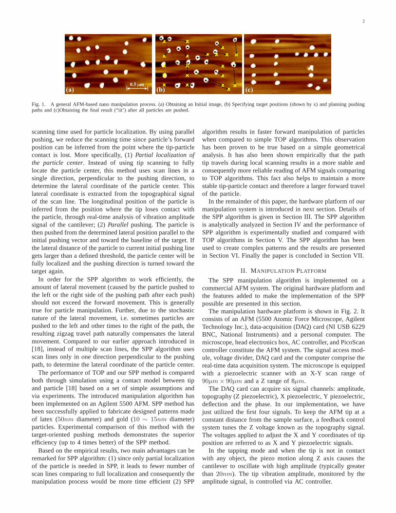
The manipulation hardware platform is shown in Fig. 2. Itconsists of an AFM (5500 Atomic Force Microscope, AgilentTechnology Inc.), data-acquisition (DAQ) card (NI USB 6229BNC, National Instruments) and a personal computer. Themicroscope, head electronics box, AC controller, and PicoScancontroller constitute the AFM system. The signal access mod-ule, voltage divider, DAQ card and the computer comprise thereal-time data acquisition system. The microscope is equippedwith a piezoelectric scanner with an X-Y scan range of90µm× 90µm and a Z range of 8µm.
The DAQ card can acquire six signal channels: amplitude,topography (Z piezoelectric), X piezoelectric, Y piezoelectric,deflection and the phase. In our implementation, we havejust utilized the first four signals. To keep the AFM tip at aconstant distance from the sample surface, a feedback controlsystem tunes the Z voltage known as the topography signal.The voltages applied to adjust the X and Y coordinates of tipposition are referred to as X and Y piezoelectric signals.
In the tapping mode and when the tip is not in contactwith any object, the piezo motion along Z axis causes thecantilever to oscillate with high amplitude (typically greaterthan 20nm). The tip vibration amplitude, monitored by theamplitude signal, is controlled via AC controller.
3
Personal computer
DAQ card
X,Y Piezoelectric Signal
Amplitude Signal
Topography Signal
AFM
Fig. 2. Hardware platform for our nanomanipulation system
The imaging and manipulation software is developed on QTutilizing the AFM and DAQ application program interfaces(APIs). The AFM API allows the user to control the motionof the tip, e.g. move or withdraw the tip and set the operationparameters, e.g. the vibration amplitude set point. The originalsystem hardware does not provide any real-time process in-formation (e.g. amplitude, deflection and friction information).Thus a DAQ card and a signal access module have been addedto the system to acquire real-time process information.
Amplitude Signal
Topography Signal
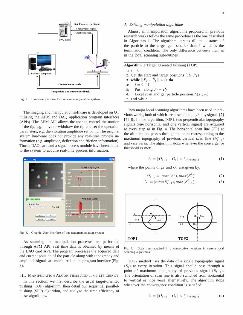
Fig. 3. Graphic User Interface of our nanomanipulation system
As scanning and manipulation processes are performedthrough AFM API, real time data is obtained by means ofthe DAQ card API. The program processes the acquired dataand current position of the particle along with topography andamplitude signals are monitored on the program interface (Fig.3).
III. M ANIPULATION ALGORITHMS AND TIME EFFICIENCY
In this section, we first describe the usual target-orientedpushing (TOP) algorithm, then detail our sequential parallel-pushing (SPP) algorithm, and analyze the time efficiency ofthese algorithms.
A. Existing manipulation algorithms
Almost all manipulation algorithms proposed in previousresearch works follow the same procedure as the one describedin Algorithm 1. The algorithm iterates till the distance ofthe particle to the target gets smaller thanδ which is thetermination condition. The only difference between them isin the local scanning subroutines.
Algorithm 1 Target Oriented Pushing (TOP)1: i = 02: Get the start and target positions(P0, Pf )3: while ||Pi − Pf || > ∆ do4: i = i+ 15: Push alongPi − Pf
6: Local scan and get particle positionPi(xi, yi)7: end while
Two major local scanning algorithms have been used in pre-vious works, both of which are based on topography signals [7][4] [8]. In first algorithm, TOP1, two perpendicular topographysignals (one horizontal and one vertical signal) are acquiredat every step as in Fig. 4. The horizontal scan line(Sh
i ) atthe ith iteration, passes through the point corresponding to themaximum topography of previous vertical scan line(Sv
i−1)and vice versa. The algorithm stops whenever the convergencethreshold is met:
δi = ‖Oi+1 −Oi‖ < δthreshold (1)
where the pointsOi+1 andOi are given by:
Oi+1 = [max(Svi ),max(Sh
i )] (2)
Oi = [max(Svi−1),max(Sh
i−1)] (3)
!"#$
!"
!"%$
!"#$
!" !"%$
&!'$ &!'(
"#$
"%$
"
"#$
"%$
"
Fig. 4. Scan lines acquired in 3 consecutive iterations in current localscanning algorithms
TOP2 method uses the data of a single topography signal(Si) at every iteration. This signal should pass through apoint of maximum topography of previous signal(Si−1).The orientation of scan line is also switched from horizontalto vertical or vice versa alternatively. The algorithm stopswhenever the convergence condition is satisfied:
δi = ‖Oi+1 −Oi‖ < δthreshold (4)
4
where the center pointsOi+1 andOi are given by:
Oi+1 = [max(Si+1)]Oi = [max(Si)] (5)
���������
���������
���
�� �
������
������
������
������
������
������
������
��������
������� ���������
� ���������
��������
���
���
���
�� �
�� ���
���
���
���
�� �
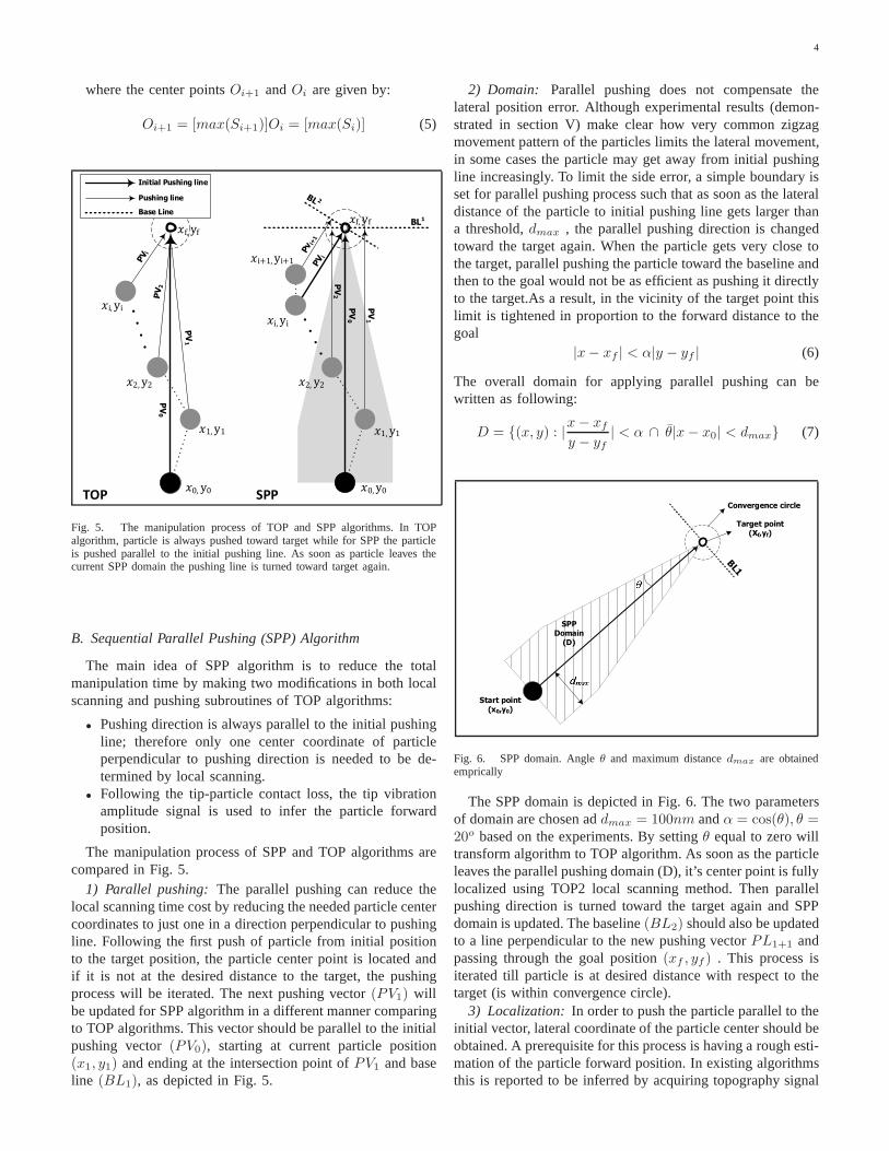
Fig. 5. The manipulation process of TOP and SPP algorithms. In TOPalgorithm, particle is always pushed toward target while for SPP the particleis pushed parallel to the initial pushing line. As soon as particle leaves thecurrent SPP domain the pushing line is turned toward target again.
B. Sequential Parallel Pushing (SPP) Algorithm
The main idea of SPP algorithm is to reduce the totalmanipulation time by making two modifications in both localscanning and pushing subroutines of TOP algorithms:
• Pushing direction is always parallel to the initial pushingline; therefore only one center coordinate of particleperpendicular to pushing direction is needed to be de-termined by local scanning.
• Following the tip-particle contact loss, the tip vibrationamplitude signal is used to infer the particle forwardposition.
The manipulation process of SPP and TOP algorithms arecompared in Fig. 5.
1) Parallel pushing: The parallel pushing can reduce thelocal scanning time cost by reducing the needed particle centercoordinates to just one in a direction perpendicular to pushingline. Following the first push of particle from initial positionto the target position, the particle center point is locatedandif it is not at the desired distance to the target, the pushingprocess will be iterated. The next pushing vector(PV1) willbe updated for SPP algorithm in a different manner comparingto TOP algorithms. This vector should be parallel to the initialpushing vector(PV0), starting at current particle position(x1, y1) and ending at the intersection point ofPV1 and baseline (BL1), as depicted in Fig. 5.
2) Domain: Parallel pushing does not compensate thelateral position error. Although experimental results (demon-strated in section V) make clear how very common zigzagmovement pattern of the particles limits the lateral movement,in some cases the particle may get away from initial pushingline increasingly. To limit the side error, a simple boundary isset for parallel pushing process such that as soon as the lateraldistance of the particle to initial pushing line gets largerthana threshold,dmax , the parallel pushing direction is changedtoward the target again. When the particle gets very close tothe target, parallel pushing the particle toward the baseline andthen to the goal would not be as efficient as pushing it directlyto the target.As a result, in the vicinity of the target pointthislimit is tightened in proportion to the forward distance to thegoal
|x− xf | < α|y − yf | (6)
The overall domain for applying parallel pushing can bewritten as following:
D = {(x, y) : |x− xf
y − yf| < α ∩ θ|x− x0| < dmax} (7)
����������������
� �� ��� �������
���
�����������
����� ��� �������
Fig. 6. SPP domain. Angleθ and maximum distancedmax are obtainedemprically
The SPP domain is depicted in Fig. 6. The two parametersof domain are chosen addmax = 100nm andα = cos(θ), θ =20o based on the experiments. By settingθ equal to zero willtransform algorithm to TOP algorithm. As soon as the particleleaves the parallel pushing domain (D), it’s center point isfullylocalized using TOP2 local scanning method. Then parallelpushing direction is turned toward the target again and SPPdomain is updated. The baseline(BL2) should also be updatedto a line perpendicular to the new pushing vectorPL1+1 andpassing through the goal position(xf , yf ) . This process isiterated till particle is at desired distance with respect to thetarget (is within convergence circle).
3) Localization: In order to push the particle parallel to theinitial vector, lateral coordinate of the particle center should beobtained. A prerequisite for this process is having a rough esti-mation of the particle forward position. In existing algorithmsthis is reported to be inferred by acquiring topography signal

5
in an iterative manner [4] [8]. The tip scans both sides of theprevious pushing vector until the existence of the particleisobserved as a change in topography signal. For SPP algorithm,we have used tip amplitude signal to infer the particle forwardposition. The planned process is illustrated in Fig. 7. Notethat our method for detecting the position where a particleis lost is similar to that in [19] except that, upon detection,SPP initiates only one lateral scan line afterwards to locatethe particle instead of full local scan with both horizontalandvertical lines.
At time t0, the AFM force feedback is turned off and tipstarts moving toward the target. As soon as the tip touches theparticle at timet1 , its vibration amplitude drops to zero andthe particle starts moving with tip. The tip loses its contactwith the particle at timet2 when it will again start vibratingand the amplitude signal will switch back to the initial valueconsequently. Estimating the time of contact loss, the forwardposition of the particle can be calculated from X and Y piezosignals.
Fig. 7. Amplitude and topography signals during the pushingprocess.
Following estimation of forward position of the particle, thelateral coordinate will be estimated by acquiring topographysignals at the inferred forward position at time . The topog-raphy scanning is repeated on the same line till the signal isstable which means:
δi = ‖Oi+1 −Oi‖ < δthreshold (8)
where the center pointsOi+1 andOi are given by:
Oi+1 = max(Si+1)Oi = max(Si) (9)
Manipulation process using SPP method is summarized inAlgorithm 2.
C. Time efficiency of manipulation algorithms
The total number of scan lines and pushing iterations arethe key parameters that determine the total manipulation time.Assuming an ideal manipulation process, the time efficiencyof introduced algorithms can be compared. The overall timeof manipulation can be formulated as following:
tt = tinit +
n∑i=1
[(zi +mi)ts + tp] (10)
Algorithm 2 Sequential Parallel Pushing1: i = 0 (iteration counter);2: Get the start and target positions(P0, Pf );3: while ||Pi − Pf || > ∆ do4: k = k + 15: P k
0 = Pi
6: while Pi in SPP Domaindo7: i = i+ 18: Push alongP k
0 − Pf from Pi up toBLk
9: SPP local scan and updatePi(xi, yi)10: end while11: Full local scanning and obtain exactPi(xi, yi)12: end while
wheretinit is Initialization time,i is the iteration step,n istotal number of pushing actions,m is the number of scan linesrequired to localize particle center at the iteration i,ts is thetime required for each scan line andtp is the time requiredfor each pushing action. Also,zi is the number of scan linesrequired to find the forward position of the particle followingeach push.
As described earlier, the SPP algorithm utilizes the am-plitude signal to locate the forward position of the particles.Hence the value ofzi for SPP algorithm is equal to zero.
In an ideal situation, the minimum and maximum number ofrequired scan lines(m) for TOP1 and TOP2 algorithms can beestimated as4 ≤ mTOP1 ≤ 6, 2 ≤ mTOP2 ≤ 3. Estimatingthis number for SPP algorithm is not that straightforward asthis algorithm may need full scanning process at some steps,but in general the algorithm will find the center line by 2scan lines. Therefore the expected value of total number ofscan lines(zi +mi) for SPP algorithm is expected to be theminimum.
This simple estimation of number of scan lines in idealsituation suggests that SPP can reduce the manipulation timeto a great extent. It should also be noted that SPP performsa more rigorous local scanning in the required directioncomparing to TOP2. Therefore we should expect to see fewernumber of pushing iterations for SPP which can furtherenhance the time efficiency of the manipulation process. Inthe following section, the performance of described algorithmswill be compared empirically and it has been shown thatSPP can shorten the manipulation time up to 4 times whencompared to two other algorithms.
IV. A LGORITHMIC PERFORMANCE VIA SIMULATION
To make the intrinsic characteristics of proposed pushingalgorithm clear and to compare it with two other introducedalgorithms, we model the travel distance for each push via asimple tip-particle contact model [18] based on a set of simpleassumptions. The AFM tip is assumed to have a conical shapewith semi-aperture angleθ, ending with a sphere of radiusRt.Particles are considered to be sphere with a radius ofRp asshown in Fig. 8. As such, we conduct a geometric analysis ofparticle movement from which we establish a stochastic modelof the particle motion and the localization process. During
6
pushing, the tip can jump over the particle [8], which shouldbetaken into consideration as part of uncertainty. Sliding happensas well that tip can bring particle to the destination withoutrelative tip-particle motion. Local scan accuracy is assumedto be the same such that only the algorithms’ pushing routinewill effect the finalized pushing trajectory.
�� ��
��
��
����������� ����� ����
����
������
�����
�������
��
��
�������
Fig. 8. (a) Side view and (b) top view of a conical AFM tip colliding witha spherical particle.
Based on the tip-particle contact model, the displacement ofthe particle in forward direction (pushing direction) and lateraldirection are given by
∆y = R
∫ α
α0
cos2 α
sinαdα
= R(cosα− cosα0 + log tanα
2− log tan
α0
2) (11)
∆x = R sinα (12)
whereR is the distance between tip center and particle centeron contact plane.α shows the direction particle laterally movesfrom the pushing line.α0 is the initial angel ofα. If tip doesnot jump over the particle during pushing process, final angelshould beπ/2. So a normal distribution is assumed to simulatethe jump-over case betweenα0 andπ/2, the contact will belost onα.
α ∼ N (π/2 − α0
2,π/2− α0
3) (13)
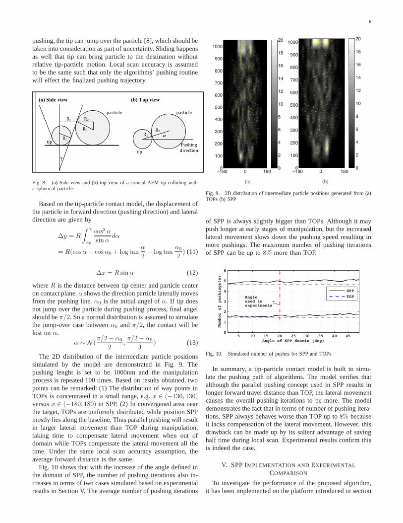
The 2D distribution of the intermediate particle positionssimulated by the model are demonstrated in Fig. 9. Thepushing lenght is set to be 1000nm and the manipulationprocess is repeated 100 times. Based on results obtained, twopoints can be remarked: (1) The distribution of way points inTOPs is concentrated in a small range, e.g.x ∈ (−130, 130)versusx ∈ (−180, 180) in SPP. (2) In convergened area nearthe target, TOPs are uniformly distributed while position SPPmostly lies along the baseline. Thus parallel pushing will resultin larger lateral movement than TOP during manipulation,taking time to compensate lateral movement when out ofdomain while TOPs compensate the lateral movement all thetime. Under the same local scan accuracy assumption, theaverage forward distance is the same.
Fig. 10 shows that with the increase of the angle defined inthe domain of SPP, the number of pushing iterations also in-creases in terms of two cases simulated based on experimentalresults in Section V. The average number of pushing iterations
−180 0 1800
100
200
300
400
500
600
700
800
900
1000
0
2
4
6
8
10
12
14
16
18
20
(a)
−180 0 1800
100
200
300
400
500
600
700
800
900
1000
0
2
4
6
8
10
12
14
16
18
20
(b)
Fig. 9. 2D distribution of intermediate particle positionsgenerated from (a)TOPs (b) SPP
of SPP is always slightly bigger than TOPs. Although it maypush longer at early stages of manipulation, but the increasedlateral movement slows down the pushing speed resulting inmore pushings. The maximum number of pushing iterationsof SPP can be up to8% more than TOP.
5 10 15 20 25 30 35 40 450
1
2
3
4
5
6
Angle of SPP doamin (deg)
Number of pushings(n)
SPP
TOPAngle used inexperiments
Fig. 10. Simulated number of pushes for SPP and TOPs
In summary, a tip-particle contact model is built to simu-late the pushing path of algorithms. The model verifies thatalthough the parallel pushing concept used in SPP results inlonger forward travel distance than TOP, the lateral movementcauses the overall pushing iterations to be more. The modeldemonstrates the fact that in terms of number of pushing itera-tions, SPP always behaves worse than TOP up to8% becauseit lacks compensation of the lateral movement. However, thisdrawback can be made up by its salient advantage of savinghalf time during local scan. Experimental results confirm thisis indeed the case.
V. SPP IMPLEMENTATION AND EXPERIMENTAL
COMPARISON
To investigate the performance of the proposed algorithm,it has been implemented on the platform introduced in section

7
II. The algorithm was applied to Latex nanoparticles with aradius of50nm deposited on a silicon substrate to push themfor a distance of1µm in air environment. Three differentlocal scanning convergence thresholds of5nm, 15nm and25nm were used to observe the effect of this parameter on theperformance of the algorithm. Each experiment was repeated10 times and the same procedure was replicated using TOP1and TOP2 algorithms to compare the performance of differentalgorithms.
Note that many process parameters that might affect themanipulation process (for instance particle size, substrateroughness and tip condition) which can affect the experimentalresults. We here report the experiments performed on twodifferent sets of particles. In one set of experiments theparticles could be moved to the final position easier and theaverage number of pushing iterations is less than 2 times.But in the other set manipulation processes required moreiterations to successfully deliver the particle to the targetposition. Besides, for the second set we could not use thelocal scanning accuracy of5nm. The reason was that the localscanning process required relatively many more scan lines toconverge and the particle was replaced during this processwhich resulted in failure of manipulation process eventually.Note that, in our experience, the SPP method has led to verygood success rate in manipulating both latex and gold particleson the silicon substrate. In latex nano particle experiments,there is less than 5% chance that a particle cannot be moveddue to strong bond between particle and substrate. We havenot further investigated the nature of this bond, it could bedueto the van der Waals force, capillary force or even chemicalbonds. In gold nanoparticle experiments, all gold nanoparticlescan be manipulated successfully by SPP.
Time and position data of all intermediate points wererecorded during pushing process. The results will be analyzedhere in time and position data subsections. Time data showsthat SPP takes the minimum manipulation time. From positiondata it has been inferred that SPP results in a faster forwardmotion; therefore the forward motion of the particles has beenanalyzed and two potential reasons for this observation hasbeen discussed.
A. Time data
Details of time data for each algorithm are given in Table I.Evidently, in all experiments SPP has the minimum manipula-tion time. This time is up to 4 times less that TOP1 algorithmfor δ = 5nm. Taking advantage of parallel pushing concept,SPP algorithm requires almost the least number of scan linesin all experiments. The amplitude signal obtained from ourexperimental platform was not accurate enough. As a result insome cases it took extra scan lines in addition to amplitudesignal to locate the particle. This fact has affected the averagenumber of scan lines required by SPP and the experimentalresults do not fully reflect the advantage of using amplitudesignal to estimate forward position of the particle.
The experimental results also show that asδ increases (thelocal scanning accuracy decreases) the number of requiredscan lines(m) decreases. Comparing the average number of
TABLE IT IME DATA OF TOPAND SPPALGORITHMS IMPLEMENTED TO PUSH A
LATEX NANOPARTICLE FOR A DISTANCE OF1µm. δ IS THE LOCALSCANNING THRESHOLD, m IS THE AVERAGE NUMBER OF SCAN LINES, n
IS THE AVERAGE NUMBER OF PUSHING ITERATIONS ANDtt(s) IS THE
AVERAGE TOTAL TIME REQUIRED FOR MANIPULATION
SET I SET IIδ(nm) Algo. m n tt(s) m n tt(s)
TOP1 16.7 4.9 80.05 TOP2 9.5 4.9 48.6 -
SPP 6.2 4.3 20.2TOP1 6.5 4.4 33.1 6.7 1.8 39.9
15 TOP2 3.5 4.9 23.0 4.6 1.4 26.6SPP 3.5 4.3 20.1 4.4 1.3 21.3
TOP1 5.1 4.4 27.0 6.2 2.1 41.825 TOP2 3.3 4.7 21.2 3.8 1.5 22.3
SPP 3.4 3.8 17.4 3.1 1.5 20.7
pushing iterations(n), TOP1 has a slightly better performancethan TOP2. This is what we expected because of the morethorough local scanning process of TOP1 algorithm. For SPP,(n) is even better than that for TOP1.
B. Position Data
The forward and lateral motion of the particles duringmanipulation process has been analyzed here.
1) Forward motion:The average forward movement of theparticle(D) is summarized in Table II for all three algorithmsand two sets of data. According to the obtained data, SPP hasthe biggestD. This means using the SPP pushing algorithmparticles approach faster to the goal comparing to TOP1 andTOP2 algorithms.
TABLE IIAVERAGE FORWARD MOVEMENT OF THE PARTICLE
δ(nm) Algo. SET I SET IITOP1 229.3 -
5 TOP2 219.2 -SPP 250.7 -
TOP1 429.5 92815 TOP2 351.1 911
SPP 492.0 953TOP1 411.9 880
25 TOP2 373.0 861SPP 414.0 952
The accumulative plot of particle travel way points obtainedfrom all ten experiments of first set is depicted in Fig. 11. Itcanbe seen that for SPP algorithm, fewer way points are locatedalong the path and they are concentrated close to the targetposition while these points are evenly distributed around theentire pushing course for TOP1 and TOP2 algorithms.
There are two main potential reasons for SPP being fasterin forward motion. Firstly, the path that tip travels duringlocalscanning process is shorter and with fewer changes in direc-tion comparing to two other algorithms. This fact has beenempirically proven to improve the stability of measurementsdone by SPP local scanning algorithm in next part. Second ofall, by a simple geometrical analysis it has been shown that theparallel pushing method of SPP algorithm justifies the fasterforward speed in part.

8
−200 0 2000
200
400
600
800
1000
1200
X(nm)
Y(nm)
TOP1
−200 0 2000
200
400
600
800
1000
1200
X(nm)
Y(nm)
TOP2
−200 0 2000
200
400
600
800
1000
1200
X(nm)Y(nm)
SPP
Fig. 11. Accumulative particle travel way points of all ten experiments plottedin X − Y plane. The local scanning threshold has beenδ = 15nm. Eachpoint shows the position of the particle after a push. The circles illustratethe convergence boundary of manipulation (r = 50nm in this case). Therectangles around points show the observed boundary of travel way points
a) Tip travel path: Pushing the particle closer to thecenterline reduces the chance of tip-particle contact loss.Therefore the local scanning accuracy directly affects thelength particle travels with the tip. It has been shown herethat the SPP local scanning process results in reading morestable signals from AFM. This fact can be a potential reasonfor SPP to push the particle toward the goal faster.
The paths tip goes through during local scanning algorithmsare compared in Fig. 12. For SPP, the scanning lines arerepeated trace and retrace lines since it only needs onecoordinate of the particle. For TOP, cross-scanning lines areneeded to fully localize the particle. The changes in directionof tip path cause disturbances due to piezoelectric actuatornonlinearities [4] which leads to imperfection in local scanningalgorithm.
Fig. 12. Tip travel path for SPP and TOP local scanning algorithms. InSPP tip scans over the same line repeatedly while for TOP algorithm the tipperforms cross scans.
To make this phenomenon explicit, both SPP and TOPlocal scanning procedures were used 10 times repeatedly tolocalize position of 5 different particles. The same experimentwas repeated 20 times for each particle. The average standarddeviations(σ) of estimated positions from 20 experiments foreach of 5 particles are given in Table III.
The results show a smallerσ for SPP algorithm in all 5cases. This implies that the center coordinate obtained using
TABLE IIITHE STANDARD DEVIATION (σ) OF ESTIMATED POTIONS OF PARTICLES
FROM SPPAND TOPLOCAL SCANNING ALGORITHMS
Particle σ (TOP) σ (SPP)1 6.2432 4.63242 5.8210 4.27813 6.2929 4.01134 6.2986 4.44595 6.5998 4.03636 6.2511 4.2808
SPP algorithm is more stable than that obtained by TOPalgorithm.
N
M
TO
P P
ush
ing
SP
P P
ush
ing
In
itial P
ush
ing
Base Line
End Line Target Position
D (
Fo
rward
Mo
vem
en
t)
Particle at step i
Y
X
o
1.0
2
0
a
b
c
L/D(Lateral to Frward Movment Ratio)
o
c
a
b
0.5
-1.0
Fig. 13. Geometrical analysis of the pushing process
b) Geometrical analysis:Assuming the same local scan-ning accuracy and consequently the same forward travelinglength (D) for SPP and TOP algorithms, the forward motionof the particle (in direction of initial pushing) is compared inFig. 13. Pushing the particle fromith step it can end up onany point on line M for SPP algorithm or line N for TOPalgorithms.
The plot on the right hand compares the distribution of theresulting position versus initial pushing angle,α0 . It can beconcluded that as the particle gets more away from initialpushing line, the possibility of particle ending up closer to thebase line is higher in case of SPP. This geometrical descriptionjustifies the observation of faster motion of particle in case ofSPP in part.
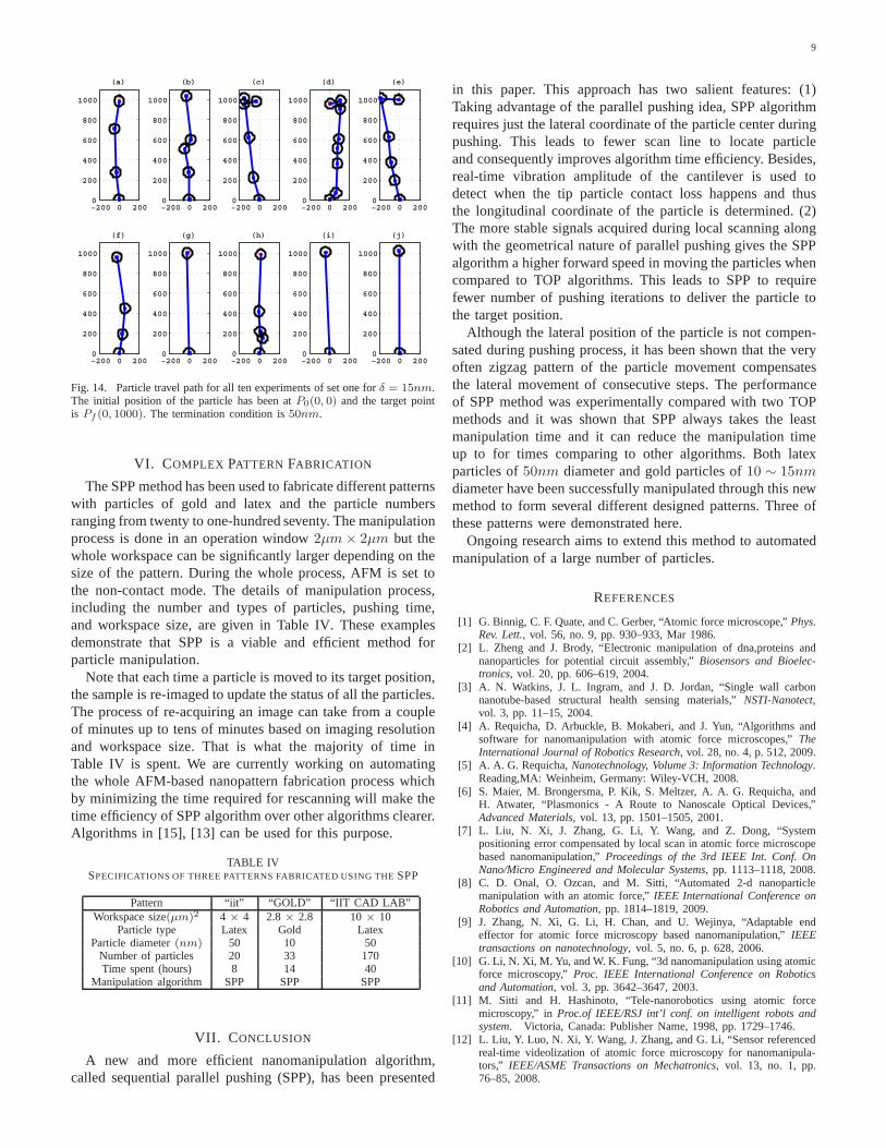
2) Lateral motion:Since the particle is just pushed forwardin SPP algorithm, the lateral movement may get large asthe particle approaches to the target. To observe how theparticle moves laterally while being pushed by SPP algorithm,the particle travel path for all ten experiments of set onewhereδ = 15nm is depicted in Fig. 14. The initial positionof the particle has been atP0(0, 0) and the target point isPf (0, 1000). Each circle shows a way point of the travel path.The travel paths in Fig. 14 (c),(d) and (e) are the worse casesthat can happen in which the lateral movement is alwaystowards one side. But paths of Fig. 14 (a), (b) , (f) and (h) showthat it is also possible that lateral movement in consecutivesteps compensate each other by forming a zigzag pattern.
9
−200 0 2000
200
400
600
800
1000
(a)
−200 0 2000
200
400
600
800
1000
(b)
−200 0 2000
200
400
600
800
1000
(c)
−200 0 2000
200
400
600
800
1000
(d)
−200 0 2000
200
400
600
800
1000
(e)
−200 0 2000
200
400
600
800
1000
(f)
−200 0 2000
200
400
600
800
1000
(g)
−200 0 2000
200
400
600
800
1000
(h)
−200 0 2000
200
400
600
800
1000
(i)
−200 0 2000
200
400
600
800
1000
(j)
Fig. 14. Particle travel path for all ten experiments of set one forδ = 15nm.The initial position of the particle has been atP0(0, 0) and the target pointis Pf (0, 1000). The termination condition is50nm.
VI. COMPLEX PATTERN FABRICATION
The SPP method has been used to fabricate different patternswith particles of gold and latex and the particle numbersranging from twenty to one-hundred seventy. The manipulationprocess is done in an operation window2µm× 2µm but thewhole workspace can be significantly larger depending on thesize of the pattern. During the whole process, AFM is set tothe non-contact mode. The details of manipulation process,including the number and types of particles, pushing time,and workspace size, are given in Table IV. These examplesdemonstrate that SPP is a viable and efficient method forparticle manipulation.
Note that each time a particle is moved to its target position,the sample is re-imaged to update the status of all the particles.The process of re-acquiring an image can take from a coupleof minutes up to tens of minutes based on imaging resolutionand workspace size. That is what the majority of time inTable IV is spent. We are currently working on automatingthe whole AFM-based nanopattern fabrication process whichby minimizing the time required for rescanning will make thetime efficiency of SPP algorithm over other algorithms clearer.Algorithms in [15], [13] can be used for this purpose.
TABLE IVSPECIFICATIONS OF THREE PATTERNS FABRICATED USING THESPP
Pattern “iit” “GOLD” “IIT CAD LAB”Workspace size(µm)2 4 × 4 2.8 × 2.8 10 × 10
Particle type Latex Gold LatexParticle diameter(nm) 50 10 50
Number of particles 20 33 170Time spent (hours) 8 14 40
Manipulation algorithm SPP SPP SPP
VII. C ONCLUSION
A new and more efficient nanomanipulation algorithm,called sequential parallel pushing (SPP), has been presented
in this paper. This approach has two salient features: (1)Taking advantage of the parallel pushing idea, SPP algorithmrequires just the lateral coordinate of the particle centerduringpushing. This leads to fewer scan line to locate particleand consequently improves algorithm time efficiency. Besides,real-time vibration amplitude of the cantilever is used todetect when the tip particle contact loss happens and thusthe longitudinal coordinate of the particle is determined.(2)The more stable signals acquired during local scanning alongwith the geometrical nature of parallel pushing gives the SPPalgorithm a higher forward speed in moving the particles whencompared to TOP algorithms. This leads to SPP to requirefewer number of pushing iterations to deliver the particle tothe target position.
Although the lateral position of the particle is not compen-sated during pushing process, it has been shown that the veryoften zigzag pattern of the particle movement compensatesthe lateral movement of consecutive steps. The performanceof SPP method was experimentally compared with two TOPmethods and it was shown that SPP always takes the leastmanipulation time and it can reduce the manipulation timeup to for times comparing to other algorithms. Both latexparticles of50nm diameter and gold particles of10 ∼ 15nmdiameter have been successfully manipulated through this newmethod to form several different designed patterns. Three ofthese patterns were demonstrated here.
Ongoing research aims to extend this method to automatedmanipulation of a large number of particles.
REFERENCES
[1] G. Binnig, C. F. Quate, and C. Gerber, “Atomic force microscope,”Phys.Rev. Lett., vol. 56, no. 9, pp. 930–933, Mar 1986.
[2] L. Zheng and J. Brody, “Electronic manipulation of dna,proteins andnanoparticles for potential circuit assembly,”Biosensors and Bioelec-tronics, vol. 20, pp. 606–619, 2004.
[3] A. N. Watkins, J. L. Ingram, and J. D. Jordan, “Single wallcarbonnanotube-based structural health sensing materials,”NSTI-Nanotect,vol. 3, pp. 11–15, 2004.
[4] A. Requicha, D. Arbuckle, B. Mokaberi, and J. Yun, “Algorithms andsoftware for nanomanipulation with atomic force microscopes,” TheInternational Journal of Robotics Research, vol. 28, no. 4, p. 512, 2009.
[5] A. A. G. Requicha,Nanotechnology, Volume 3: Information Technology.Reading,MA: Weinheim, Germany: Wiley-VCH, 2008.
[6] S. Maier, M. Brongersma, P. Kik, S. Meltzer, A. A. G. Requicha, andH. Atwater, “Plasmonics - A Route to Nanoscale Optical Devices,”Advanced Materials, vol. 13, pp. 1501–1505, 2001.
[7] L. Liu, N. Xi, J. Zhang, G. Li, Y. Wang, and Z. Dong, “Systempositioning error compensated by local scan in atomic forcemicroscopebased nanomanipulation,”Proceedings of the 3rd IEEE Int. Conf. OnNano/Micro Engineered and Molecular Systems, pp. 1113–1118, 2008.
[8] C. D. Onal, O. Ozcan, and M. Sitti, “Automated 2-d nanoparticlemanipulation with an atomic force,”IEEE International Conference onRobotics and Automation, pp. 1814–1819, 2009.
[9] J. Zhang, N. Xi, G. Li, H. Chan, and U. Wejinya, “Adaptableendeffector for atomic force microscopy based nanomanipulation,” IEEEtransactions on nanotechnology, vol. 5, no. 6, p. 628, 2006.
[10] G. Li, N. Xi, M. Yu, and W. K. Fung, “3d nanomanipulation using atomicforce microscopy,”Proc. IEEE International Conference on Roboticsand Automation, vol. 3, pp. 3642–3647, 2003.
[11] M. Sitti and H. Hashinoto, “Tele-nanorobotics using atomic forcemicroscopy,” inProc.of IEEE/RSJ int’l conf. on intelligent robots andsystem. Victoria, Canada: Publisher Name, 1998, pp. 1729–1746.
[12] L. Liu, Y. Luo, N. Xi, Y. Wang, J. Zhang, and G. Li, “Sensorreferencedreal-time videolization of atomic force microscopy for nanomanipula-tors,” IEEE/ASME Transactions on Mechatronics, vol. 13, no. 1, pp.76–85, 2008.

10
�����
������� ��������� �
��
Fig. 15. Complex patterns fabricated using SPP. (a)“iit” pattern composed of 20 latex nanoparticles; (b) “GOLD” pattern composed of 33 gold nanoparticles(c);“IIT CAD LAB” pattern composed of 170 latex nanoparticles.
[13] B. Mokaberi and A. A. G. Requicha, “Compensation of scanner creepand hysteresis for afm nanominipulation,”IEEE Transactions on Au-tomation Science and Engineering, vol. 5, pp. 197–206, 2008.
[14] B. A. Mantooth, Z. J. Donhauser, K. F. Kelly, and P. S. Weiss, “Cross-correction image tracking for drift correction and absorbate analysis,”Review of scientific instruments, vol. 73, no. 2, pp. 313–317, 2001.
[15] Z. Xu, X. Li, M. A. Sutton, and N. Li, “Drift and spatial distortionelimination in atomic force microscopy images by the digital imagecorrection technique,”J. Strain Analysis, vol. 43, pp. 729–743, 2008.
[16] B. Mokaberi and A. A. G. Requicha, “Drift compensation for automaticnanomanipulation with scanning probe microscopes,”IEEE Transactionson Automation Science and Engineering, vol. 3, pp. 199–207, 2006.
[17] L. Liu, N. Xi, Y. Wang, Z. Dong, and U. Wejinya, “LandmarkBasedSensing and Positioning in Robotic Nano Manipulation,”Proceedingsof the IEEE Int. Conf. On Robotics and Biomimetics, pp. 37–42, 2008.
[18] A. Rao, E. Gnecco, D. Marchetto, K. Mougin, M. Sch”onenberger, S. Valeri, and E. Meyer, “The analytical relations betweenparticles and probe trajectories in atomic force microscope nanomanip-ulation,” Nanotechnology, vol. 20, p. 115706, 2009.
[19] H. Xie and S. Regnier, “High-efficiency automated nanomanipulationwith parallel imaging/manipulation force microscopy,”Nanotechnology,IEEE Transactions on, no. 99, pp. 1–1, 2010.
[20] M. Tomitori and T. Arai, “Tip cleaning and sharpening processes fornoncontact atomic force microscope in ultrahigh vacuum,”Appliedsurface science, vol. 140, no. 3-4, pp. 432–438, 1999.
Related Documents