G E N E R A L C I V I L S T R U C T U R A L P R O C E S S PROCESS MECHANICAL UTILITY MECHANICAL ELECTRICAL

Welcome message from author
This document is posted to help you gain knowledge. Please leave a comment to let me know what you think about it! Share it to your friends and learn new things together.
Transcript

G E N E R A L
C I V I L
S T R U C T U R A L
P R O C E S S
PROCESS MECHANICAL
UTILITY MECHANICAL
ELECTRICAL

DIS
TR
IC
T O
F S
UM
ME
RLA
ND
WA
ST
EW
AT
ER
T
RE
AT
ME
NT
F
AC
ILIT
Y U
PG
RA
DE
Suite 400
1620 D
ickson A
venue
Kelow
na, B
C V
1Y
9Y
2
Phone: (250) 860-3225
Fax: (250) 860-3367
ww
w.stantec.com
FIL
TE
R P
RO
CE
SS
U
PG
RA
DE
G-002
SIT
E P
LA
N
SITE PLAN
KEY NOTES

DIS
TR
IC
T O
F S
UM
ME
RLA
ND
WA
ST
EW
AT
ER
T
RE
AT
ME
NT
F
AC
ILIT
Y U
PG
RA
DE
Suite 400
1620 D
ickson A
venue
Kelow
na, B
C V
1Y
9Y
2
Phone: (250) 860-3225
Fax: (250) 860-3367
ww
w.stantec.com
FIL
TE
R P
RO
CE
SS
U
PG
RA
DE
C-101
SIT
E G
RA
DIN
G
SITE GRADING PLAN
KEY NOTESLEGEND:

DIS
TR
IC
T O
F S
UM
ME
RLA
ND
WA
ST
EW
AT
ER
T
RE
AT
ME
NT
F
AC
ILIT
Y U
PG
RA
DE
Suite 400
1620 D
ickson A
venue
Kelow
na, B
C V
1Y
9Y
2
Phone: (250) 860-3225
Fax: (250) 860-3367
ww
w.stantec.com
FIL
TE
R P
RO
CE
SS
U
PG
RA
DE
C-102
YA
RD
P
IP
IN
G
YARD PIPING PLAN
KEY NOTESLEGEND:

DIS
TR
IC
T O
F S
UM
ME
RLA
ND
WA
ST
EW
AT
ER
T
RE
AT
ME
NT
F
AC
ILIT
Y U
PG
RA
DE
Suite 400
1620 D
ickson A
venue
Kelow
na, B
C V
1Y
9Y
2
Phone: (250) 860-3225
Fax: (250) 860-3367
ww
w.stantec.com
ABBREVIATIONS
A.B. anchor boltA.F. alternate facesARCH architecturalBLDG buildingBOT bottomC.I.P. cast in placeCL centre lineC.J. control jointCOL columnCONC concreteCONST. JT. construction jointCONT continuousC/W complete withDP deepDWG drawingEA eachE.F. each faceE.W. each wayELEV. elevationEMBED embedmentEQUIP equipmentFDN foundationF.F. far faceFLR floorFTG footingGA gaugeGALV galvanizedGL gridlineH1E hooked 1 endH2E hooked both endsH & HORIZ. horizontalJT jointKG kilogramLONG. longitudinal barsMAX. maximumMIN. minimumMFR manufacturerMPa megapascalN.F. near faceNTS not to scaleO.C. on centreOWSJ open Web steel joistPL plateREINF. reinforcingREQ'D requiredR/W reinforce withSECT sectionSIM. similarS.O.G. slab on gradeSPEC specificationSQ squareSTAGG staggeredSTD standardSTIFF. stiffenerSTL steelSTRUCT. structuralSYMM symmetricalTHK thickT.O.F. top of footingT.O.S. top of steelTRANS. transverse barsTYP typicalT&B top & bottomU.N.O. unless noted otherwiseU/S undersideV & VERT. verticalW.W.M. welded wire mesh
WALL THICKNESS VERTICAL REINF. HORIZONTAL REINF.
200mm
15M @ 500 O.C. 15M @ 400 O.C.
250mm
15M @ 400 O.C. 15M @ 300 O.C.
300mm
15M @ 500 O.C. each face 15M @ 500 O.C. each face
LOCATION EXPOSURE CLASS 28 DAY STRENGTH
MAX. COARSE
AGGREGATE
Footings & foundation walls
A1 35 MPa 20 mm
Slabs on grade, Interior
A1 30 MPa 20 mm
Slabs on grade, Exterior
A2 32 MPa 20 mm
Suspended slabs, beams, columns,
walls
35 MPa 20 mm
SLAB THICKNESS
REINFORCEMENT (fy = 400 MPa)
100mm to 150mm
10M @ 300mm O.C.
150mm to 200mm
10M @ 250mm O.C. 150 min. to 200mm
200mm to 250mm
10M @ 400mm O.C. 200 min. to 250mm
BAR SPLICE / LAP LENGTHS:
SIZE 25 MPa 30 MPa 35 MPa
10M 380 350 330
15M 560 510 490
20M 760 690 640
25M 1170 1070 990
30M 1410 1290 1190
2-20M 3200
Two 3200 long 20M bars
4-C15M 1600
Four 15M bars w/ a 90Á standard hook at one end, 1600mm long (including hook)
2-15M H1E 600
Two 15M bars. each w/ a 90Á standard hook at one end, hook length is 600mm
EXPOSURE CONDITION N*F-1, F-2, S-1, S-2
C-XL, C-1, C-3, A-1,
A-2, A-3
Cast against and permanently exposed to earth
- 75mm 75mm
Beams, girders, columns, and piles
30mm 40mm 60mm
Slabs, walls, joists, shells, and folded plates
20mm 40mm 60mm
Ratio of covered to nominal bar diameter 1.0 1.5 2.0
Ratio of cover to nominal maximum aggregate size
1.0 1.5 2.0
Ss = kPa
q(50)
kPa
Sr = kPa
S = kPa + Accumulation
S-001
FIL
TE
R P
RO
CE
SS
U
PG
RA
DE
EF
FL
UE
NT
F
IL
TE
RS
GE
NE
RA
L N
OT
ES

1
S300
2
S300
4
S300
3
S300
DIS
TR
IC
T O
F S
UM
ME
RLA
ND
WA
ST
EW
AT
ER
T
RE
AT
ME
NT
F
AC
ILIT
Y U
PG
RA
DE
Suite 400
1620 D
ickson A
venue
Kelow
na, B
C V
1Y
9Y
2
Phone: (250) 860-3225
Fax: (250) 860-3367
ww
w.stantec.com
S-101
FIL
TE
R P
RO
CE
SS
U
PG
RA
DE
EF
FL
UE
NT
F
IL
TE
RS
FO
UN
DA
TIO
N P
LA
N

2
S300
4
S300
1
S300
3
S300
DIS
TR
IC
T O
F S
UM
ME
RLA
ND
WA
ST
EW
AT
ER
T
RE
AT
ME
NT
F
AC
ILIT
Y U
PG
RA
DE
Suite 400
1620 D
ickson A
venue
Kelow
na, B
C V
1Y
9Y
2
Phone: (250) 860-3225
Fax: (250) 860-3367
ww
w.stantec.com
S-102
FIL
TE
R P
RO
CE
SS
U
PG
RA
DE
EF
FL
UE
NT
F
IL
TE
RS
MA
IN
F
LO
OR
P
LA
N

150 PVC WATERSTOP
SEE TYP DETAIL
1
1
2
150 PVC WATERSTOP
SEE TYP DETAIL
1
1
DIS
TR
IC
T O
F S
UM
ME
RLA
ND
WA
ST
EW
AT
ER
T
RE
AT
ME
NT
F
AC
ILIT
Y U
PG
RA
DE
Suite 400
1620 D
ickson A
venue
Kelow
na, B
C V
1Y
9Y
2
Phone: (250) 860-3225
Fax: (250) 860-3367
ww
w.stantec.com
S300
FIL
TE
R P
RO
CE
SS
U
PG
RA
DE
EF
FL
UE
NT
F
IL
TE
RS
SE
CT
IO
NS
KEY NOTES

DIS
TR
IC
T O
F S
UM
ME
RLA
ND
WA
ST
EW
AT
ER
T
RE
AT
ME
NT
F
AC
ILIT
Y U
PG
RA
DE
Suite 400
1620 D
ickson A
venue
Kelow
na, B
C V
1Y
9Y
2
Phone: (250) 860-3225
Fax: (250) 860-3367
ww
w.stantec.com
S500
FIL
TE
R P
RO
CE
SS
U
PG
RA
DE
EF
FL
UE
NT
F
IL
TE
RS
DE
TA
IL
S

DIS
TR
IC
T O
F S
UM
ME
RLA
ND
WA
ST
EW
AT
ER
T
RE
AT
ME
NT
F
AC
ILIT
Y U
PG
RA
DE
Suite 400
1620 D
ickson A
venue
Kelow
na, B
C V
1Y
9Y
2
Phone: (250) 860-3225
Fax: (250) 860-3367
ww
w.stantec.com
S501
FIL
TE
R P
RO
CE
SS
U
PG
RA
DE
EF
FL
UE
NT
F
IL
TE
RS
DE
TA
IL
S

DIS
TR
IC
T O
F S
UM
ME
RLA
ND
WA
ST
EW
AT
ER
T
RE
AT
ME
NT
F
AC
ILIT
Y U
PG
RA
DE
Suite 400
1620 D
ickson A
venue
Kelow
na, B
C V
1Y
9Y
2
Phone: (250) 860-3225
Fax: (250) 860-3367
ww
w.stantec.com
S502
FIL
TE
R P
RO
CE
SS
U
PG
RA
DE
EF
FL
UE
NT
F
IL
TE
RS
DE
TA
IL
S

DIS
TR
IC
T O
F S
UM
ME
RLA
ND
WA
ST
EW
AT
ER
T
RE
AT
ME
NT
F
AC
ILIT
Y U
PG
RA
DE
Suite 400
1620 D
ickson A
venue
Kelow
na, B
C V
1Y
9Y
2
Phone: (250) 860-3225
Fax: (250) 860-3367
ww
w.stantec.com
S503
FIL
TE
R P
RO
CE
SS
U
PG
RA
DE
EF
FL
UE
NT
F
IL
TE
RS
DE
TA
IL
S

~
DIS
TR
IC
T O
F S
UM
ME
RLA
ND
WA
ST
EW
AT
ER
T
RE
AT
ME
NT
F
AC
ILIT
Y U
PG
RA
DE
Suite 400
1620 D
ickson A
venue
Kelow
na, B
C V
1Y
9Y
2
Phone: (250) 860-3225
Fax: (250) 860-3367
ww
w.stantec.com
S504
FIL
TE
R P
RO
CE
SS
U
PG
RA
DE
EF
FL
UE
NT
F
IL
TE
RS
DE
TA
IL
S

EQUIPMENT SYMBOLS VALVE SYMBOLS
GENERAL ABBREVIATIONS
VALVE ACTUATORS/OPERATOR
GATE SYMBOLS
PIPE LINE DEVICES
COMMODITY LIST
PROCESS EQUIPMENT ABREVIATIONS
PROCESS IDENTIFIERS
PIPE & CHANNEL IDENTIFICATION
VALVE, GATE & WEIR IDENTIFICATION
EQUIPMENT IDENTIFICATION
DIS
TR
IC
T O
F S
UM
ME
RLA
ND
WA
ST
EW
AT
ER
T
RE
AT
ME
NT
F
AC
ILIT
Y U
PG
RA
DE
Suite 400
1620 D
ickson A
venue
Kelow
na, B
C V
1Y
9Y
2
Phone: (250) 860-3225
Fax: (250) 860-3367
ww
w.stantec.com
FIL
TE
R P
RO
CE
SS
U
PG
RA
DE
P-001
PR
OC
ES
S ID
EN
TIF
IC
AT
IO
N,
AB
BR
EV
IA
TIO
N &
S
YM
BO
LS

VCP
ACP
RELAY FUNCTION DESIGNATORS
DIS
TR
IC
T O
F S
UM
ME
RLA
ND
WA
ST
EW
AT
ER
T
RE
AT
ME
NT
F
AC
ILIT
Y U
PG
RA
DE
Suite 400
1620 D
ickson A
venue
Kelow
na, B
C V
1Y
9Y
2
Phone: (250) 860-3225
Fax: (250) 860-3367
ww
w.stantec.com
FIL
TE
R P
RO
CE
SS
U
PG
RA
DE
P-002
IN
ST
RU
ME
NT
AT
IO
N L
EG
EN
D &
S
YM
BO
LS

GENERAL NOTES
DIS
TR
IC
T O
F S
UM
ME
RLA
ND
WA
ST
EW
AT
ER
T
RE
AT
ME
NT
F
AC
ILIT
Y U
PG
RA
DE
Suite 400
1620 D
ickson A
venue
Kelow
na, B
C V
1Y
9Y
2
Phone: (250) 860-3225
Fax: (250) 860-3367
ww
w.stantec.com
FIL
TE
R P
RO
CE
SS
U
PG
RA
DE
P-101
PR
OC
ES
S &
IN
ST
RU
ME
NT
AT
IO
N D
IA
GR
AM
EF
FL
UE
NT
F
IL
TE
R 2

GENERAL NOTES
DIS
TR
IC
T O
F S
UM
ME
RLA
ND
WA
ST
EW
AT
ER
T
RE
AT
ME
NT
F
AC
ILIT
Y U
PG
RA
DE
Suite 400
1620 D
ickson A
venue
Kelow
na, B
C V
1Y
9Y
2
Phone: (250) 860-3225
Fax: (250) 860-3367
ww
w.stantec.com
FIL
TE
R P
RO
CE
SS
U
PG
RA
DE
P102
PR
OC
ES
S &
IN
ST
RU
ME
NT
AT
IO
N D
IA
GR
AM
EF
FL
UE
NT
F
IL
TE
R 3

DIS
TR
IC
T O
F S
UM
ME
RLA
ND
WA
ST
EW
AT
ER
T
RE
AT
ME
NT
F
AC
ILIT
Y U
PG
RA
DE
Suite 400
1620 D
ickson A
venue
Kelow
na, B
C V
1Y
9Y
2
Phone: (250) 860-3225
Fax: (250) 860-3367
ww
w.stantec.com
FIL
TE
R P
RO
CE
SS
U
PG
RA
DE
M-001
ST
AN
DA
RD
D
ET
AIL
S
SH
EE
T 1
DIS
TR
IC
T O
F S
UM
ME
RLA
ND
WA
ST
EW
AT
ER
T
RE
AT
ME
NT
F
AC
ILIT
Y U
PG
RA
DE
Suite 400
1620 D
ickson A
venue
Kelow
na, B
C V
1Y
9Y
2
Phone: (250) 860-3225
Fax: (250) 860-3367
ww
w.stantec.com
FIL
TE
R P
RO
CE
SS
U
PG
RA
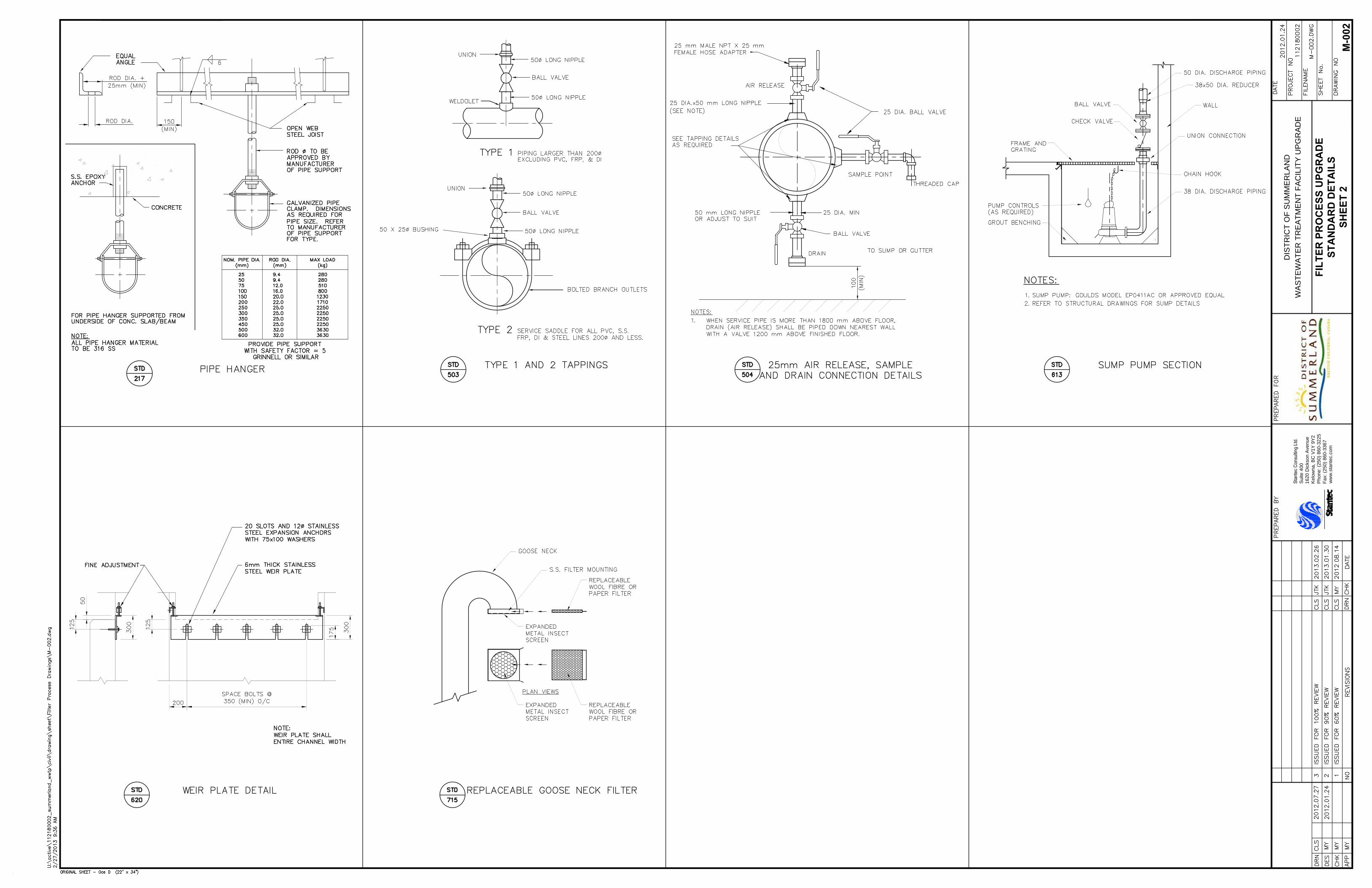
DE
M-002
ST
AN
DA
RD
D
ET
AIL
S
SH
EE
T 2

DIS
TR
IC
T O
F S
UM
ME
RLA
ND
WA
ST
EW
AT
ER
T
RE
AT
ME
NT
F
AC
ILIT
Y U
PG
RA
DE
Suite 400
1620 D
ickson A
venue
Kelow
na, B
C V
1Y
9Y
2
Phone: (250) 860-3225
Fax: (250) 860-3367
ww
w.stantec.com
FIL
TE
R P
RO
CE
SS
U
PG
RA
DE
M-101
EF
FL
UE
NT
F
IL
TE
RS
PL
AN
PLAN

DIS
TR
IC
T O
F S
UM
ME
RLA
ND
WA
ST
EW
AT
ER
T
RE
AT
ME
NT
F
AC
ILIT
Y U
PG
RA
DE
Suite 400
1620 D
ickson A
venue
Kelow
na, B
C V
1Y
9Y
2
Phone: (250) 860-3225
Fax: (250) 860-3367
ww
w.stantec.com
FIL
TE
R P
RO
CE
SS
U
PG
RA
DE
M-102
EF
FL
UE
NT
F
IL
TE
RS
SE
CT
IO
NS
A
ND
D
ET
AIL
S
SECTION
SECTION

DIS
TR
IC
T O
F S
UM
ME
RLA
ND
WA
ST
EW
AT
ER
T
RE
AT
ME
NT
F
AC
ILIT
Y U
PG
RA
DE
Suite 400
1620 D
ickson A
venue
Kelow
na, B
C V
1Y
9Y
2
Phone: (250) 860-3225
Fax: (250) 860-3367
ww
w.stantec.com
FIL
TE
R P
RO
CE
SS
U
PG
RA
DE
M-103
EF
FL
UE
NT
F
IL
TE
RS
SE
CT
IO
NS
A
ND
D
ET
AIL
S
SECTION
SECTION
TYP. ROTATING SKIMMER DETAIL
TYP. SUMP PUMP DETAIL
SCUM PUMP DETAIL


E-100
FIL
TE
R P
RO
CE
SS
U
PG
RA
DE
SIN
GL
E L
IN
E D
IA
GR
AM
DIS
TR
IC
T O
F S
UM
ME
RLA
ND
WA
ST
EW
AT
ER
T
RE
AT
ME
NT
F
AC
ILIT
Y U
PG
RA
DE
Suite 400
1620 D
ickson A
venue
Kelow
na, B
C V
1Y
9Y
2
Phone: (250) 860-3225
Fax: (250) 860-3367
ww
w.stantec.com

DIS
TR
IC
T O
F S
UM
ME
RLA
ND
WA
ST
EW
AT
ER
T
RE
AT
ME
NT
F
AC
ILIT
Y U
PG
RA
DE
Suite 400
1620 D
ickson A
venue
Kelow
na, B
C V
1Y
9Y
2
Phone: (250) 860-3225
Fax: (250) 860-3367
ww
w.stantec.com
E-101
FIL
TE
R P
RO
CE
SS
U
PG
RA
DE
MD
C / M
CC
M
OT
OR
S
CH
ED
UL
E

DIS
TR
IC
T O
F S
UM
ME
RLA
ND
WA
ST
EW
AT
ER
T
RE
AT
ME
NT
F
AC
ILIT
Y U
PG
RA
DE
Suite 400
1620 D
ickson A
venue
Kelow
na, B
C V
1Y
9Y
2
Phone: (250) 860-3225
Fax: (250) 860-3367
ww
w.stantec.com
E-102
FIL
TE
R P
RO
CE
SS
U
PG
RA
DE
MC
C E
LE
VA
TIO
N

DIS
TR
IC
T O
F S
UM
ME
RLA
ND
WA
ST
EW
AT
ER
T
RE
AT
ME
NT
F
AC
ILIT
Y U
PG
RA
DE
Suite 400
1620 D
ickson A
venue
Kelow
na, B
C V
1Y
9Y
2
Phone: (250) 860-3225
Fax: (250) 860-3367
ww
w.stantec.com
E-103
FIL
TE
R P
RO
CE
SS
U
PG
RA
DE
FIL
TE
R R
OO
M E
LE
CT
RIC
AL
P
LA
N

DIS
TR
IC
T O
F S
UM
ME
RLA
ND
WA
ST
EW
AT
ER
T
RE
AT
ME
NT
F
AC
ILIT
Y U
PG
RA
DE
Suite 400
1620 D
ickson A
venue
Kelow
na, B
C V
1Y
9Y
2
Phone: (250) 860-3225
Fax: (250) 860-3367
ww
w.stantec.com
E-104
FIL
TE
R P
RO
CE
SS
U
PG
RA
DE
CO
NT
RO
L S
CH
EM
AT
IC
S

District of Summerland
Wastewater Treatment Plant Effluent Filters Upgrade Volume 1 of 1
Prepared for:
District of Summerland Prepared by:
Stantec Consulting Ltd. DRAFT (100% Submission)
February 2013
Stantec Project No: 112180002

District of Summerland Section 00005 Effluent Filters Upgrade Contents of Tendering Conditions
February 2013 - 1 - Tender No. xxx-xxx
PROJECT DESCRIPTION:
CONTRACT FORMS & CONDITIONS Pages PRE-TENDER INFORMATION Section 00005 Contents of Tendering Conditions 1 - 1 Section 00030 Invitation to Tender 1 - 1 Section 00100 Instructions to Tenderers 1 - 7 INFORMATION FOR TENDERS Section 00220 Soil Investigation Data 1 - 1 Section 00230 Existing Site Conditions 1 - 1
END OF DOCUMENT

District of Summerland Section 00030 Effluent Filters Upgrade Invitation to Tender
February 2013 -1- Tender No. xxx-xxx
District of Summerland Tender No. XXXX
Wastewater Treatment Plant Effluent Filters Upgrade
SEALED Tenders, clearly marked, ‘Tender No. XXXX : ‘Wastewater Treatment Plant – Effluent Filters Upgrade’ will be received at District of Summerland, Engineering and Public Works Department, 9215 Cedar Avenue, Summerland, BC, V0H 1Z0 up to 2:00 PM Local Time, Thursday _______, 2013. Tenders will be opened at 2:01 PM on this date.
The work includes the following major items:
Construction of new wastewater effluent filters and installation of Owner supplied cloth media disk filter equipment (manufactured by Aqua Aerobics).
Reinforced concrete, miscellaneous metals, masonry, process mechanical, electrical, instrumentation, HVAC, demolition, site works, and related works.
Supply and installation of auxiliary equipment, structures and systems required to complete the work.
Tenders shall be accompanied by a Bank Draft in the amount of Ten (10%) Percent of the Total Tender Amount, payable to the District of Summerland or, a Surety Bid Bond accompanied by a Consent of Surety, in an amount equal to Ten Percent (10%) of the Tender Price.
Contract Documents may be obtained from District of Summerland Engineering and Public works, 9215 Cedar Avenue, Summerland, BC, V0H 1Z0 (Tel: xxx-xxx-xxxx) on or after __________, 2013 upon payment of Two Hundred and Fifty Dollars ($250.00) per set (GST included) which sum will be non-refundable. Cheques should be made payable to District of Summerland.
Tender Documents will be available for viewing at the District of Summerland Engineering and Public Works; or at the following locations of the Southern Interior Construction Association (SICA) offices: #104 – 151 Commercial Drive, Kelowna, BC (800) 661-7322; and the Vancouver Regional Construction Association (VRCA), 3636 East 4th Avenue, Vancouver, BC (604) 294-3766; and BC BID.
The District of Summerland reserves the right to waive informalities in or reject any or all tenders or accept the tender deemed most favourable in the interests of the District of Summerland. Without limiting the generality of the forgoing, any Tender which is incomplete, obscure, irregular, has erasures or corrections in the price sheet, unit prices omitted, or is accompanied by an insufficient or irregular Tender Security, may be rejected. Awards shall be made on tenders that will give the greatest value based on quality, service and price. The District of Summerland will not accept responsibility for the costs incurred by a Tenderer for the preparation and submission of a Tender or, for loss of potential profits where a Tender is not awarded. The lowest or any Tender will not necessarily be accepted.
All enquiries shall be directed to the Purchasing Agent, District of Summerland by emailing [email protected] and quoting the tender / contract number. Reponses shall be posted to the District of Summerland webpage.
A pre-tender meeting will be held at 10:00 a.m. Tuesday or Thursday, 2013. Tenderers shall meet at the WWTP Administration Building, 7630 Dunn Street, Summerland BC V0H 1Z4, which will be followed by a site tour. All attendees wishing to view the plant shall supply their own hardhat, vest and eyewear. Attendance is optional for all General Contractors.

District of Summerland Section 00100 Effluent Filters Upgrade Instructions to Tenderers
Feburary 2013 -1- Tender No. xxx-xxx
TABLE OF CONTENTS
ARTICLE NUMBER ARTICLE
Page
1. Tendering Conditions 2
2. Information Concerning Conditions of the Work 2
3. Addenda 3
4. Discrepancies, Omissions and Constructability 3
5. Requests for Review of Equivalent Alternatives 4
6. Alternative Proposals 4
7. Subcontractors 4
8. Suppliers and Manufacturers 5
9. Tender Guarantee 5
10. Tender Evaluation 6
11. Acceptance or Rejection of Tenders 6
12. 24 HOUR BREAKDOWN 7
TOTAL PAGES 7

District of Summerland Section 00100 Effluent Filters Upgrade Instructions to Tenderers
Feburary 2013 -2- Tender No. xxx-xxx
1. TENDERING CONDITIONS
.1 The TENDER shall be submitted in a sealed, clearly marked envelope and directed to the attention of the OWNER’s Receiving Officer: District of Summerland Engineering and Public Works, 9215 Cedar Avenue, Summerland, BC, V0H 1Z0.
.2 The TENDER, including all Schedules, shall be submitted on the separate forms provided. The Tenderer's legal status and business address shall be disclosed. The TENDER shall be signed by a duly authorized official and in the case of a corporation, shall be sealed with the corporate seal.
.3 The Tendering Period shall end at the time and date specified in the "Invitation to Tender," or at an extended time and date specified in a Written Notice.
.4 After a Tender has been received by the Owner's Receiving Officer designated in Paragraph 1.1, but before the expiry of the Tendering Period specified in Paragraph 1.3, the Tenderer may withdraw or modify its Tender but only in accordance with the following procedure:
.1 Notify the Owner's Receiving Officer in writing, or by Facsimile. The notice by Facsimile must be confirmed in a timely manner by sending by registered mail, a copy of the Written Notice signed and sealed in the same manner as was the Tender.
.2 Proof of receipt of the Written Notice will be an acknowledgment by return Telegram or Facsimile by the Owner.
.3 All faxed withdrawals or modifications of tenders shall be made in writing to the District of Summerland Engineering and Public Works, 9215 Cedar Avenue, Summerland, BC, V0H 1Z0 at (250) ________. Such faxed withdrawals or modifications, regardless of the time such fax is sent, must be received at the District of Summerland Engineering and Public Works no later than 15 minutes prior to the time of tender closing. The Owner does not guarantee receipt of faxed withdrawals or modifications, and is not responsible for any technical or equipment malfunctions or delays experienced in fax transmission or receipt. All faxed modifications received after the above noted time will not be accepted.
.5 The Instructions to Tenderers are provided as information for the tendering process in the period prior to submission of a TENDER. The Instructions to Tenderers are not a part of the CONTRACT DOCUMENTS nor of the CONTRACT.
2. INFORMATION CONCERNING CONDITIONS OF THE WORK
.1 TENDERERS shall carefully examine the CONTRACT DOCUMENTS and the WORKSITE, and shall fully inform themselves as to all existing conditions and limitations which will affect the execution of the CONTRACT. No consideration

District of Summerland Section 00100 Effluent Filters Upgrade Instructions to Tenderers
Feburary 2013 -3- Tender No. xxx-xxx
will be given after submission of a TENDER to any claim that there was any misunderstanding with respect to the conditions imposed by the CONTRACT.
.2 In preparation of a TENDER, TENDERERS shall use only those drawings listed in the CONTRACT DOCUMENTS that are clearly labeled "ISSUED FOR TENDER". TENDERERS shall not rely on any documents that are not so labeled.
.3 Discussions at TENDER Briefings or other oral discussions shall not become a part of the CONTRACT DOCUMENTS nor modify the CONTRACT DOCUMENTS unless confirmed by Addenda issued to all TENDERERS before closing.
3. ADDENDA
.1 If there are to be any changes in THE WORK, TENDERERS will be informed, prior to the close of the period allowed for receiving TENDERS, by means of an ADDENDUM, a written communication issued by the OWNER. All ADDENDA shall become a part of the CONTRACT DOCUMENTS, and receipt of ADDENDA shall be acknowledged by the TENDERER in the TENDER.
.2 ADDENDA will not be issued later than three (3) calendar days before the TENDER closing date.
.3 After TENDERS have been opened, no changes, additions, or deletions to any TENDER, except those specifically provided for in the Tendering Conditions shall be made either by or on behalf of the OWNER, or by or on behalf of the TENDERER.
4. DISCREPANCIES, OMISSIONS AND CONSTRUCTABILITY
.1 If a TENDERER finds discrepancies or errors or omissions in the drawings, specifications, or other documents or has any doubt as to the meaning or intent of any part thereof, he shall at once inform the OWNER. Any necessary changes, or additions, or further explanations, will be made by the OWNER by issuing an ADDENDUM.
.2 Every request for an interpretation shall be made in writing, and forwarded to the address given on the Invitation to Tender. Oral discussions, unless confirmed in writing in an Addendum, shall not modify the CONTRACT DOCUMENTS nor the tendering procedure.
.3 The TENDERER is responsible for gaining an understanding of the intent of the design as conveyed by the CONTRACT DOCUMENTS, adequate to allow the TENDERER to prepare a valid TENDER. The TENDERER shall be responsible for determining that THE WORK is constructable in accordance with the intent of the design.

District of Summerland Section 00100 Effluent Filters Upgrade Instructions to Tenderers
Feburary 2013 -4- Tender No. xxx-xxx
5. REQUESTS FOR REVIEW OF EQUIVALENT ALTERNATIVES
.1 The TENDERER shall submit any requests for review of equivalent alternatives to the ENGINEER at least 10 working days prior to the TENDER closing date.
.2 Requests for consideration of alternative PRODUCT shall be submitted in writing and directed to the ENGINEER, and shall contain pertinent data such as construction and operation characteristics.
.3 The OWNER may allow the alternative, and issue an ADDENDUM to the CONTRACT, or he may reject the alternative.
.4 The TENDERER shall use only alternatives that are confirmed by an ADDENDUM.
.5 Whenever alternatives are accepted, the TENDERER shall be responsible for making all consequent adjustments to make the alternative fit into THE WORK as specified, and the consequent costs shall be deemed to be included in the TENDER PRICE.
6. ALTERNATIVE PROPOSALS
.1 A TENDERER may submit a Schedule of Alternative Proposals as provided in the Supplementary Tender Forms in which he may list one or more alternative MATERIAL, PRODUCT or construction methods, regardless of whether the specifications provide for consideration of equivalent alternatives. Full descriptive details shall be submitted with a statement for each alternative, including the increase in cost or decrease in cost if the OWNER accepts that alternative. The Alternative Proposals will be considered only after TENDERS close, and the OWNER may accept or reject any or all of the Alternative Proposals. Any Alternative Proposal which is not specifically accepted shall be considered rejected.
.2 For every item for which an Alternative Proposal is submitted, the TENDERER must tender a price for that item as originally specified and his proposed increase or decrease if the alternative is used. The change in price tendered in the Alternative Proposal shall be added to or subtracted from the price tendered for the item as originally specified.
.3 Whenever alternatives are accepted, the TENDERER shall be responsible for making all consequent adjustments to make the alternative fit into THE WORK as specified, and these consequent costs shall be deemed to be included in the price difference tendered for the alternative proposal.
7. SUBCONTRACTORS
.1 The TENDERER shall submit in the Schedule of Subcontractors the names of SUBCONTRACTORS proposed for the work.

District of Summerland Section 00100 Effluent Filters Upgrade Instructions to Tenderers
Feburary 2013 -5- Tender No. xxx-xxx
.2 Where the Schedule of Subcontractors shows specific items of work the TENDERER shall name his SUBCONTRACTOR; or if the work will not be subcontracted he shall so indicate using the words "Own Forces".
.3 The SUBCONTRACTORS listed in the Tender may not be changed without the written consent of the OWNER. If the OWNER so requires, the TENDERER shall be prepared to confirm to the OWNER the competence of SUBCONTRACTORS prior to their acceptance on THE WORK.
.4 If at the time of Contract Award a SUBCONTRACTOR named in the Tender is not acceptable to the OWNER, the TENDERER shall name an alternative SUBCONTRACTOR acceptable to the owner.
8. SUPPLIERS AND MANUFACTURERS
.1 The TENDERER shall submit in the Schedule of Suppliers and Manufacturers of MATERIAL and PRODUCT, the names of Manufacturers, and if MATERIAL and PRODUCT are obtained through intermediate agents, the agents shall be indicated as the Suppliers.
.2 The Suppliers and Manufacturers named in the TENDER shall not be changed without the written consent of the OWNER.
.3 If, at the time of Contract Award a Supplier and/or Manufacturer named in the TENDER is not acceptable to the OWNER, the TENDERER shall name an alternative Supplier or Manufacturer acceptable to the Owner.
9. TENDER GUARANTEE
.1 The TENDER shall be accompanied by a Bid Bond in the amount of ten (10) percent of the CONTRACT PRICE and a Consent of Surety for the Performance Bond and Labour and Materials Payment Bond, in the amounts specified in the Tender Invitation. The Bid Bond and Consent of Surety shall be provided in an acceptable form by an agency that is acceptable to the OWNER, and licensed in the jurisdiction of the project. Alternatively the TENDERER may provide a certified cheque for the ten (10) percent of the CONTRACT PRICE or other form of TENDER Guarantee acceptable to the OWNER.
.2 The obligation of the Tender Guarantee shall be that if the OWNER accepts a TENDER and the TENDERER refuses to sign the AGREEMENT and to provide the specified performance guarantees, then the Tender Guarantee shall be forfeited to the OWNER.
.3 In the event that the OWNER’s damages arising from default of the Tenderer in failing to perform the CONTRACT after acceptance of its Tender are greater than the amount of the Tender Guarantee, the Tender Guarantee shall not be construed to limit or eliminate the OWNER’s right to sue for the balance of its damages or for all of its damages and that right may be exercised by the OWNER in its sole discretion.

District of Summerland Section 00100 Effluent Filters Upgrade Instructions to Tenderers
Feburary 2013 -6- Tender No. xxx-xxx
10. TENDER EVALUATION
.1 The OWNER reserves the right to evaluate TENDERS on the basis of criteria of its own choice, in its sole discretion, whether previously disclosed to TENDERERS or not, provided only that the reasons for selection of a TENDER shall not be frivolous, irrelevant, or malicious.
.2 In evaluation of TENDERS the OWNER may, but is not obligated to, apply preference for:
a) a local Contractor over non-local;
b) an earlier completion date over later;
c) a Contractor deemed by the OWNER in its sole discretion to be more competent than a less competent, (even though both may be competent to perform THE WORK).
.3 In evaluation of TENDERS the OWNER may, but is not obligated to, consider previous or on-going disputes from other CONTRACTS, with a TENDERER.
11. ACCEPTANCE OR REJECTION OF TENDERS
.1 The OWNER reserves the right to reject any or all TENDERS, to waive irregularities and informalities at his discretion and to accept the TENDER which the OWNER deems to be in its best interest. The lowest TENDER will not necessarily be accepted. Without limiting the generality of the foregoing, any TENDER may be rejected for any of the following reasons:
- Incomplete TENDER. - Obscured or irregular erasures or corrections in the Schedule Of Prices. - Prices omitted or unbalanced. - Insufficient or irregular Tender Guarantees. - Evidence of inadequate experience, or of inadequate capacity to perform
the contract, or failure to qualify under conditions of the Tendering Requirement.
- Evidence of previous failure to perform adequately on similar work. - The insertion by the Tenderer of conditions which vary the Tendering
Requirements or the Tender Forms.
.2 No action of the OWNER other than a written "Notice of Acceptance" shall constitute an acceptance of a TENDER. Such written notice shall be in the form included in the Contract Documents and shall be signed by officials properly authorized by the OWNER to do so, and either under the seal of the OWNER, or witnessed, as may be appropriate for the OWNER.
.3 The OWNER reserves its right to negotiate at the time of acceptance, with the lowest TENDERER only, for a lower TENDER PRICE, or for the removal from the TENDER of qualifying conditions, or both.

District of Summerland Section 00100 Effluent Filters Upgrade Instructions to Tenderers
Feburary 2013 -7- Tender No. xxx-xxx
12. 24 HOUR BREAKDOWN
.1 All tenders forms at time of submittal as a minimum shall include sub-totals and total pricing for the Schedule of Prices and Schedule of Provisional Work Items.
.2 Submittal of the detailed breakdown of Schedule of Prices and Schedule of Provisional Work Items and Schedules of Alternative Proposals, Schedule of Subcontractors and Schedule of Manufacturers / Suppliers must be faxed to District of Summerland Engineering and Public Works Services, 9215 Cedar Avenue, Summerland, BC, V0H 1Z0 (250) _____________within 24 hours of closing.
END OF DOCUMENT

District of Summerland Section 00220 Effluent Filters Upgrade Soil Investigation Data
Feburary 2013 - 1 - Tender No. xxx-xxx
PART 1 GENERAL
1.1 GEOTECHNICAL REPORT
.1 A geotechnical report has been prepared for the Owner’s use in design and it is attached herein in Appendix A.
The geotechnical report has been prepared by Beacon Geotechnical Ltd, Kelowna, BC dated November 5, 2012.
.2 Any information pertaining to soils and borehole logs is furnished by the Owner as a matter of general information only and borehole descriptions or logs are not to be interpreted as descriptive of conditions at locations other than those of the borehores themselves. Neither the Owner nor the Engineer warrants or makes any representation with respect to data or interpretations of data or opinions expressed in any geotechnical report available for the perusal of the Contractor, whether or not such report is included as part of the Tender or Contract Documents.
.3 The Tenderer should familiarize himself with the purpose and limitations of the geotechnical report when interpreting subsurface conditions for Tender preparation purposes.
END OF SECTION

District of Summerland Section 00230 Effluent Filters Upgrade Existing Site Conditions
February 2013 -1- Tender No. xxx-xxx
PART 1 GENERAL
1.1 EXISTING SITE CONDITIONS
.1 TENDERERS must visit the site and examine site conditions.
.2 TENDERERS may make tests, inspections and measurements, but such investigations must be performed under time schedules and arrangements with the OWNER and TENDERERS must comply with the OWNER'S requirements.
.3 TENDERERS must take note of the following particular existing site conditions:
Maintenance of existing wastewater treatment plant operation, facilities and underground utilities.
END OF SECTION

District of Summerland Section 00303 Effluent Filters Upgrade Contents of the Contract Documents
February 2013 -1- Tender No. xxx-xxx
CONTENTS OF THE CONTRACT DOCUMENTS
CONTRACT FORMS & CONDITIONS Pages Section 00303 Contents of the Contract Documents 1 - 6 Section 00304 Tender Forms 1 - 11 Section 00400 Supplementary Tender Forms 1 - 8 Section 00500 Agreement 1 - 4 Section 00600 Bonds and Certificates 1 - 2 Section 00700 General Conditions 1 - 34 Section 00800 Supplementary General Conditions 1 - 7 SPECIFICATIONS- DIVISION 1 TO 17
DIVISION 1 GENERAL REQUIREMENTS
Section 01010 Section 01014
Summary of the Work Work Sequence
Section 01015 Contractor's Use of the Premises Section 01040 Coordination Section 01050 Field Engineering Section 01060 Regulatory Requirements Section 01065 Special Project Requirements Section 01070 Abbreviations Section 01080 Identification Systems Section 01100 Alternatives Section 01150 Measurement and Payment Section 01200 Project Meetings Section 01300 Submittals Section 01310 Construction Schedules Section 01340 Shop Drawings Section 01380 Construction Photographs Section 01390 Drawings of Record Section 01400 Quality Control Section 01500 Construction Facilities Section 01561 Environmental Protection Section 01562 Waste Management Section 01600 Material and Installation Section 01650 Equipment Installation Section 01670 Commissioning and Handover Section 01700 Contract Closeout DIVISION 2 SITEWORK
Section 02224 Excavation and Site Work Section 02650 Underground Piping DIVISION 4 MASONRY
Section 04200 Masonry DIVISION 5 METALS
Section 05500 Miscellaneous Metals

District of Summerland Section 00303 Effluent Filters Upgrade Contents of the Contract Documents
February 2013 -2- Tender No. xxx-xxx
DIVISION 6 WOOD AND PLASTICS
Section 06100 Rough Carpentry Section 06200 Finish Carpentry Section 06600 Fiberglass Reinforced DIVISION 7 THERMAL AND MOISTURE PROTECTION
Section 07190 Air Vapor Barrier Section 07200 Building Insulation Section 07500 Membrane Roofing Section 07610 Sheet Metal Roofing Section 07620 Flashing and Trim Section 07625 Rainwater Leaders Section 07900 Sealant DIVISION 8 DOORS AND WINDOWS
Section 08101 Hollow Steel Doors Section 08102 Steel Door Frames Section 08331 Coiling Doors Section 08520 Alum Windows Section 08710 Hardware Section 08800 Glass and Glazing DIVISION 9 FINISHES
Section 09000 Room Finish Schedule Section 09900 Painting DIVISION 10 SPECIALTIES
Section 10400 Signage DIVISION 11 PROCESS MECHANICAL
Section 11100 General Provisions Section 11101 Pre Purchase Section 11102 Testing Section 11150 Process Piping Section 11160 Process Valves Section 11161 Scum Skimmer Pipe Section 11201 Slide Gates Section 11202 Weir Boxes and Gates Section 11431 Effluent Cloth Media Disc Filter Installation Section 11910 Identification, Process Piping & Equipment DIVISION 13 SPECIAL CONSTRUCTION
Section 13010 Instrumentation and Control General Required Section 13015 Scope of Work Section 13110 Enclosures Section 13127 Industrial Ethernet Network Section 13213 Powered Actuators Section 13400 Instrumentation Requirements Section 13701 Instrumentation Specifications Sheets Section 13702 Instrumentation Loop Drawings Section 13800 Commissioning, Testing and Training Section 13900 Control Panel

District of Summerland Section 00303 Effluent Filters Upgrade Contents of the Contract Documents
February 2013 -3- Tender No. xxx-xxx
DIVISION 15 BUILDING MECHANICAL
Section 15010 Mechanical General Section 15015 Testing, Balancing, and Commissioning Section 15190 Identification Section 15242 Seismic Restraints Section 15270 Insulation for Ducting Section 15505 Fire Exit Section 15015 Testing, Balancing, and Commissioning Section 15810 Duct Work Section 15820 Duct Accessories Section 15830 Air Distribution Equipment Section 15830 Fans Section 15850 Air Outlets Section 15925 Controls Section 15955 Mechanical Forms Section 15965 Manufactures Section 15966 Sub-Contractor DIVISION 16 ELECTRICAL
Section 16010 General Electrical Requirements Section 16030 Testing Of Equipment Section 16045 Seismic Section 16050 Basic Materials and Methods Section 16105 Ducts Section 16110 Conduits, Fastenings, and Fittings Section 16114 Cable Tray Section 16122 Wires & Cables Section 16130 Splitters Pull boxes Section 16132 Conduit Boxes Section 16140 Wiring Devices Section 16150 Motors Section 16160 Grounding Section 16165 Secondary Grounding Section 16190 Fastening and Supports Section 16420 Distribution Transformers Section 16430 Panel Boards Section 16501 General Requirements - Lighting Section 16510 Battery Operated Emergency and Exit Luminaires Section 16515 Lamps, Luminaires, Ballasts and Accessories Section 16705 Fire alarm Section 16742 Structured Cabling Section 16890 Electric Heating Section 16970 Testing General
DIVISION 17 INSTRUMENTATION AND CONTROLS
Section 17010 Instrumentation and Control General Requirements Section 17015 Instrumentation and Control Scope of Work Section 17110 Enclosures Section 17124 Instrumentation Cable

District of Summerland Section 00303 Effluent Filters Upgrade Contents of the Contract Documents
February 2013 -4- Tender No. xxx-xxx
Appendix A - Geotechnical Report
Appendix B - Aqua Aerobic Effluent Cloth Media Disk Filter Shop Drawing (Bound Separately)
END OF DOCUMENT

District of Summerland Section 00304 Effluent Filters Upgrade Tender Forms
February 2013 -1- Tender No. xxx-xxx
TABLE OF CONTENTS
ARTICLE NUMBER ARTICLE
Page
T-1 Contractor 2
T-2 Owner 2
T-3 Project Description 2
T-4 Basis of the Tender 2
T-5 Schedule of Prices 3
T-6 Schedule of Completions 6
T-6 A Liquidated Damages 6
T-7 Schedule of Addenda 6
T-8 Performance Guarantee and Insurance Certificate 7
T-9 Agreement 7
T-10 Notice to Proceed 7
T-11 Period of Irrevocability 7
T-12 Signatures 8
TOTAL PAGES 8

District of Summerland Section 00304 Effluent Filters Upgrade Tender Forms
February 2013 -2- Tender No. xxx-xxx
T-1 Contractor
Name
Address
Phone / Fax
T-2 Owner
Name District of Summerland
Address 9215 Cedar Avenue Summerland, BC, V0H 1Z0
T-3 Project Description
Construction of wastewater effluent filters including site works, demolition, concrete, masonry, process mechanical, electrical, instrumentation, building mechanical, commissioning and other related works.
T-4 Basis of the Tender
1. The CONTRACTOR has carefully examined the CONTRACT DOCUMENTS for the construction of THE WORK.
2. The CONTRACT DOCUMENTS are an integral part of this TENDER.
3. The CONTRACTOR has examined the WORKSITE and understands the conditions under which THE WORK is to be performed. The CONTRACTOR has satisfied himself that THE WORK is constructible.
4. The CONTRACTOR offers to furnish all of the MATERIAL and PRODUCT (except as otherwise specified to be supplied by others), together with all of the labour, to perform THE WORK described in the CONTRACT DOCUMENTS, in the manner prescribed therein, for the prices quoted in the Schedule of Prices, and in accordance with the other Schedules in this TENDER.
5. Where Prime Cost Sums for provision of MATERIAL or PRODUCT are included in the Schedule of Prices, only actual expenditures made upon the written authority of the OWNER, shall be paid out of these Prime Cost Sums, and if a Prime Cost Sum is not sufficient to cover that component of the work, then the CONTRACT PRICE shall be increased, and if the Prime Cost Sum is greater than required, the CONTRACT PRICE shall be decreased.
Prime Cost Sums shall include the net cost of the item, applicable taxes and duties and delivery to the Site. Prime Cost Sums shall not include handling at the site, protection, installation or overhead and profit. Allowance for handling, protection, installation, overhead and profit shall be made by the CONTRACTOR in his tendered prices for installation. The tendered prices for installation will not be adjusted if the actual cost of

District of Summerland Section 00304 Effluent Filters Upgrade Tender Forms
February 2013 -3- Tender No. xxx-xxx
the Prime Cost item has increased or decreased from the Prime Cost Sum in the TENDER.
6. Where Provisional Cost Sums for portions of THE WORK are included in the Schedule of Prices, only actual expenditures made upon the written authority of the OWNER, shall be paid out of these Provisional Cost Sums, and if the Provisional Cost Sum is not sufficient to cover THE WORK, then the CONTRACT PRICE shall be increased, and if the Provisional Cost Sum is greater than required for THE WORK, the CONTRACT PRICE shall be decreased.
7. Where a Contingency Allowance is included in the Schedule of Prices, only actual expenditures for increases in the quantities and changes in THE WORK, made upon the written authority of the OWNER, will be paid out of such allowance, and the CONTRACT PRICE will be changed in the amount by which the Contingency Allowance either exceeds or is exceeded by such expenditures.
8. Any equivalent alternatives used in this TENDER shall receive a final detailed review at the time of submission of shop drawings, and if an equivalent alternative is rejected at that time, the CONTRACTOR shall provide the item as originally specified at no change in the CONTRACT PRICE.
9. The estimated quantities of work are approximate only and are subject to increase or decrease, and whether the quantities are increased or decreased, the unit prices stated in the Schedule of Prices shall apply, and the CONTRACT PRICE shall be adjusted accordingly.
10. If a discrepancy is found between a Unit Price and an Amount, the Unit Price shall be considered as representing the intention of the CONTRACTOR, and the OWNER will recalculate the Amount. The addition of the Amounts will be corrected and a corrected TENDER Amount and CONTRACT PRICE will be established.
If a discrepancy is found between the sum of the corrected Amounts and the Tender Price shown, the sum of Amounts, as corrected shall be deemed to represent the intent of the Tenderer.
11. If a discrepancy is found between a Lump Sum Price and the corresponding Breakdown Prices, the Lump Sum Price shall be considered as representing the intention of the CONTRACTOR.
12. No action of the Owner other than sending a "Notice of Acceptance" in writing to the CONTRACTOR, shall constitute acceptance of a Tender. The Notice of Acceptance shall be in the form included in the CONTRACT DOCUMENTS as Document 00305.
T-5 Schedule of Prices
The CONTRACTOR offers the following Schedule of Prices for performance of the CONTRACT.

District of Summerland Section 00304 Effluent Filters Upgrade Tender Forms
February 2013 -4- Tender No. xxx-xxx
Schedule A – General Conditions (All Schedules)
Item No.
Specification and/or Description
Unit Price
Amount
A.1 General Requirements – Division 1
a) Mobilization & Demobilization Lump Sum $
b) Start-up and Commissioning Lump Sum $
Total Schedule A – General Conditions $
Schedule B – Effluent Filters
Item No.
Specification and/or Description
Unit Price
Amount
B.1 Site Work – Division 2
a) Underground Piping Lump Sum $
b) Demolition and Removal Lump Sum $
c) Dewatering Lump Sum $
d) Excavation and Backfill Lump Sum $
e) Paving Lump Sum $
f) Temporary Works Lump Sum $
B.2 Concrete – Division 3 Lump Sum $
B.3 Miscellaneous Metals – Division 5 Lump Sum $
B.4 Thermal & Moisture Protection – Division 7 Lump Sum $
B.5 Doors & Windows – Division 8 Lump Sum $
B.6 Finishes – Division 9 Lump Sum $
Schedule B – Effluent Filters
Item No.
Specification and/or Description
Unit Price
Amount
B.7 Process Mechanical – Division 11
B.7.1 Process Mechanical Equipment and Piping
a) Install Owner-Supplied Mechanical Equipment Lump Sum $
b) Supply & Install All Other Mechanical Equipment
Lump Sum $
c) Process Piping, Valves and Fittings Lump Sum $
d) Gates Lump Sum $
B.8 Building Mechanical – Division 15 Lump Sum $
B.9 Electrical – Division 16
a) Install Owner-Supplied Electrical Equipment
Lump Sum $
b) Supply & Install All Other Electrical Equipment and Wiring
Lump Sum $
c) Distribution, MCCs and Control Panels Lump Sum $

District of Summerland Section 00304 Effluent Filters Upgrade Tender Forms
February 2013 -5- Tender No. xxx-xxx
Item No.
Specification and/or Description
Unit Price
Amount
d) Lighting Lump Sum $
e) Site Electrical Lump Sum $
B.10 Controls and Instrumentation – Division 17
a) Install Owner-Supplied Control Panels and Instrumentation
Lump Sum $
b) Interconnecting Cabling Lump Sum $
c) Software Supply Lump Sum $
Total Schedule B – Effluent Filters $
SUMMARY OF TENDER
Schedule A – General Conditions Total $ Schedule B – Waste Water Treatment Plant Total $
Sub-total $
Federal Goods & Services Tax at 5.0% $
TOTAL CONTRACT PRICE (including GST) $

District of Summerland Section 00304 Effluent Filters Upgrade Tender Forms
February 2013 -6- Tender No. xxx-xxx
T-6 Schedule of Completions
1. The CONTRACTOR offers to begin THE WORK within the period specified in the "Notice to Proceed," and to prosecute THE WORK in such a manner as to achieve the following completion periods. Completion includes all clean-up and rectification of all deficiencies.
THE WORK shall be completed entirely in 240 calendar days from the date of commencement specified in the “Notice to Proceed”.
2. Time is of the Essence in this CONTRACT, and in the event that THE WORK is not completed within the period named above, the CONTRACTOR shall be responsible for all damages accruing to the OWNER due to late completion.
T-6A Liquidated Damages
1. The designated portion of THE WORK is described as follows: Total completion of the work including commissioning.
The designated portion of THE WORK shall be completed entirely in 240 Calendar Days (the Designated Completion Period).
2. If THE WORK is not completed within the Designated Completion Period, the CONTRACTOR shall pay to the OWNER Liquidated Damages of ($500 Five hundred and 00/100 dollars per Calendar day for each calendar day in excess of the Designated Completion Period until THE WORK is entirely completed. These costs will be deducted from Progress Payments and shall be used to offset additional costs incurred by the Owner for late completion.
3. There shall be no exclusion of time from the Designated Completion Period for any reason OTHER than delays clearly attributable to the OWNER, its agents, employees or any other authorized Representatives.
T-7 Schedule of Addenda
1. The CONTRACTOR states that he has received the following ADDENDA which have been considered and taken into account in determining the Prices tendered in the Schedule of Prices. The ADDENDA are issued by or in behalf of the Owner.
Addendum Number Date Issued Number of Pages

District of Summerland Section 00304 Effluent Filters Upgrade Tender Forms
February 2013 -7- Tender No. xxx-xxx
T-8 Performance Guarantee and Insurance Certificate
1. After receipt of Notice of Acceptance, the CONTRACTOR shall provide a Performance Bond in the amount of 50% of the CONTRACT PRICE and a standard Labour and Materials Payment Bond in the amount of 50% of the CONTRACT PRICE and the Bonds shall remain in effect for the duration of construction and the Warranty Period.
2. The bonds shall be in a form that is acceptable to the OWNER and shall be supplied by an agency that is acceptable to the OWNER and that is licensed in the jurisdiction in which THE WORK is located.
3. In the event that a Security Deposit is provided in lieu of a Performance Bond, the Security Deposit shall be retained to the end of the Warranty Period.
4. After receipt of Notice of Acceptance, the CONTRACTOR shall provide the required Insurance Certificate.
5. The costs of bonds and insurance shall be borne by the CONTRACTOR.
6. No Progress Payments shall be made until the required Bonds or Security Deposit and Insurance Certificate have been delivered to the OWNER.
T-9 Agreement
1. The CONTRACTOR shall sign the AGREEMENT within fourteen (14) calendar days after receipt of the Notice of Acceptance.
T-10 Notice to Proceed
1. After acceptance, the OWNER will issue a "Notice to Proceed" and the date specified in this Notice shall be the date of commencement entered into the AGREEMENT.
2. The CONTRACTOR shall not enter onto the WORKSITE nor commence work before the date of commencement specified in the "Notice to Proceed."
T-11 Period of Irrevocability
This TENDER is irrevocable for 60 days after the TENDER closing date.
TENDER Closing Date: ____________, 2013.

District of Summerland Section 00304 Effluent Filters Upgrade Tender Forms
February 2013 -8- Tender No. xxx-xxx
T-12 Signatures
Name of CONTRACTOR
Legal Status Corporation, Partnership or Sole Ownership
Correct Mailing Address
Names and Addresses of Corporation Officers or Members of the Organization:
Name Address Position
Name Address Position
Name Address Position
SIGNED, SEALED AND DELIVERED BY:
Signature of Witness Signature of CONTRACTOR
(Corporate Name (Seal Here Address
END OF DOCUMENT

Distric of Summerland Section 00400 Effluent Fitlers Upgrade Supplementary Tender Forms
February 2013 -1- Tender No. xxx-xxx
TABLE OF CONTENTS
ARTICLE NUMBER ARTICLE
Page
1. Content of Supplementary Tender Forms 2
2. Schedule of Unit Prices for Provisional Work Items 3
3. Schedule of Force Account Rates 3
4. Schedule of Alternative Proposals 4
5. Schedule of Contractor's Qualifications 4
6. Schedule of Equipment 5
7. Schedule of Contractor's Supervisory Personnel 5
8. Schedule of Subcontractors 6
9. Schedule of Manufacturers/Suppliers of Material and Product 6
TOTAL PAGES 6

Distric of Summerland Section 00400 Effluent Fitlers Upgrade Supplementary Tender Forms
February 2013 -2- Tender No. xxx-xxx
1. CONTENT OF SUPPLEMENTARY TENDER FORMS
.1 The Schedules in the Supplementary Tender Forms are offered for information and are subject to review by the OWNER, who may require these Schedules to be modified before the award of the CONTRACT. Modifications may be required for good cause, including but not limited to:
- unbalanced breakdown prices. - unacceptable SUBCONTRACTORS or Suppliers and Manufacturers. - unacceptable Force Account Rates. - unacceptable provisional unit prices. - unacceptable supervisory personnel. - other causes.
The CONTRACTOR warrants that all of the information given in these Schedules is current and correct. Changes to any schedule in the supplementary Tender Forms, agreed upon by the OWNER and the CONTRACTOR, after closing of the Tender Period but before Contract Award shall not in any way affect the Validity of the Tender.
.2 Upon acceptance by the OWNER, all Schedules in the Supplementary Tender Forms shall become a part of the CONTRACT DOCUMENTS.
.3 Table of Contents:
2 SCHEDULE OF UNIT PRICES FOR PROVISIONAL WORK ITEMS 3 SCHEDULE OF FORCE ACCOUNT RATES 4 SCHEDULE OF ALTERNATIVE PROPOSALS 5 SCHEDULE OF CONTRACTOR'S QUALIFICATIONS 6 SCHEDULE OF EQUIPMENT 7 SCHEDULE OF CONTRACTOR'S SUPERVISORY PERSONNEL 8 SCHEDULE OF SUBCONTRACTORS 9 SCHEDULE OF MANUFACTURERS / SUPPLIERS OF MATERIAL AND
PRODUCT

Distric of Summerland Section 00400 Effluent Fitlers Upgrade Supplementary Tender Forms
February 2013 -3- Tender No. xxx-xxx
2. SCHEDULE OF UNIT PRICES FOR PROVISIONAL WORK ITEMS
.1 The CONTRACTOR offers the following Schedule of Unit Prices to be used as information for the specific provisional work items listed. Actual expenditures for provisional work made upon the written authority of the OWNER will be paid out of the Provisional Cost Sum changes negotiated in the Unit Prices shall not change the provisional cost sum tendered.
.2 These items or units of work do not represent the scope of work currently included in the T-5 Schedule of Prices.
Schedule D – Provisional Work Items (transfer to Section 00304)
Item No.
Specification and/or Description Unit Quantity
Unit Price
Amount
Total Schedule D – Provisional Work Items (transfer to Section 00304)
$
3. SCHEDULE OF FORCE ACCOUNT RATES
.1 The CONTRACTOR offers to do force account work for the following rates for personnel and equipment. Equipment rates include operator, fuel, maintenance, profit and overhead. Personnel rates include payroll cost of labour, all payroll burdens, room and board, if applicable, overhead and profit. The cost of superintendents, time keepers, and other administrative and supervisory personnel and their vehicles are included in overhead. The cost of Bonding and Insurance is included in overhead.
.2 The CONTRACTOR understands that the OWNER may review these Force Account Rates and require changes for good cause.
EQUIPMENT: Description and Make Model and Size Hourly Rate
PERSONNEL: Occupation Or Trade Hourly Rate Overtime Rate

Distric of Summerland Section 00400 Effluent Fitlers Upgrade Supplementary Tender Forms
February 2013 -4- Tender No. xxx-xxx
4. SCHEDULE OF ALTERNATIVE PROPOSALS
.1 The CONTRACTOR offers the following alternative units of PRODUCT, MATERIAL or methods of doing THE WORK, and offers to increase or decrease the Price as stated for each unit of PRODUCT, MATERIAL or methods of doing THE WORK, and to increase or decrease the CONTRACT PRICE. The increase or decrease includes allowance for the cost of making any adjustments to THE WORK which may be required in order to make the proposed alternative fit into THE WORK as originally specified. The tendered increase or decrease in price shall be added to or subtracted from the price tendered for the work as originally specified.
.2 If the OWNER accepts an Alternative Proposal, as offered, or after negotiation, the increase or decrease in the price tendered for the work as originally specified, shall be implemented by a CHANGE ORDER after Award of the CONTRACT and the CONTRACT price shall then be changed.
.3 Alternative Proposals not specifically accepted by the OWNER are deemed to be rejected.
Item No.
Specification Section No.
Original Item
Alternative Item (Make / Model)
Price Difference
1
2
3
4
5
6 Item No.
Specifications Section No.
Original Item
Tendered Price
Alternative Item
Alternative Price
Price Difference
5. SCHEDULE OF CONTRACTOR'S QUALIFICATIONS
.1 The CONTRACTOR states that the following is a true account of his qualifica-tions and experience on work similar to THE WORK.

Distric of Summerland Section 00400 Effluent Fitlers Upgrade Supplementary Tender Forms
February 2013 -5- Tender No. xxx-xxx
Work Year Construction Cost Owner/Engineer
6. SCHEDULE OF EQUIPMENT
.1 The CONTRACTOR states that the equipment listed or its equivalent shall be available for THE WORK on this CONTRACT.
Description of Unit
Size or Capacity
Condition
Age
Present Location
7. SCHEDULE OF CONTRACTOR'S SUPERVISORY PERSONNEL
.1 The CONTRACTOR states that the following supervisory personnel shall be employed on this CONTRACT.
Name Position Experience

Distric of Summerland Section 00400 Effluent Fitlers Upgrade Supplementary Tender Forms
February 2013 -6- Tender No. xxx-xxx
8. SCHEDULE OF SUBCONTRACTORS
.1 The CONTRACTOR states that the following SUBCONTRACTORS shall be utilized on this CONTRACT:
.2 The CONTRACTOR agrees that if a named SUBCONTRACTOR is not acceptable to the OWNER, the CONTRACTOR shall name an alternative SUBCONTRACTOR, which is acceptable to the OWNER, before Award of the CONTRACT.
Items of Work Subcontractor Excavation Concrete Misc. Steel Painting Underground Piping Process Mechanical Building Mechanical Electrical Instrumentation SCADA / Programming
9. SCHEDULE OF MANUFACTURERS/SUPPLIERS OF MATERIAL AND PRODUCT
.1 The CONTRACTOR states that the following MANUFACTURERS/SUPPLIERS of MATERIAL and PRODUCT shall be utilized for the major supply items on this CONTRACT.
Item Supplier Manufacturer
Slide Gates
Sump Pumps
.2 The CONTRACTOR agrees that, if a named MANUFACTURER/SUPPLIER is not acceptable to the OWNER, the CONTRACTOR shall name an alternative, acceptable to the OWNER, before Award of the CONTRACT.
END OF DOCUMENT

District of Summerland Section 00500 Effluent Filters Upgrade Agreement
February 2013 -1- Tender No. xxx-xxx /
TABLE OF CONTENTS
ARTICLE NUMBER ARTICLE
Page
1. The Parties to the Contract and the Date of the Agreement 2
2. Scope of the Work 2
3. Completion Dates 2
4. Payment 3
5. Contract Price 3
6. Performance Guarantees 3
7. Written Notice 3
8. Signatures 4
TOTAL PAGES 4

District of Summerland Section 00500 Effluent Filters Upgrade Agreement
February 2013 -2- Tender No. xxx-xxx /
1. THE PARTIES TO THE CONTRACT AND THE DATE OF THE AGREEMENT
THIS AGREEMENT made in Triplicate on the ____ day of _________, 2013 by and between:
District of Summerland
Hereinafter called the "OWNER" and
Hereinafter called the "CONTRACTOR"
The OWNER and the CONTRACTOR agree as follows:
2. SCOPE OF THE WORK
.1 The CONTRACTOR agrees to furnish all of the MATERIAL and PRODUCT (except as otherwise specified to be supplied by others) together with all of the equipment, labour and transportation necessary to perform entirely THE WORK as described in the CONTRACT DOCUMENTS entitled:
Tender No. XXXX
“Wastewater Treatment Plant – Effluent Filters Upgrade”
The CONTRACT DOCUMENTS have been prepared by Stantec Consulting Ltd. and include all documents listed in the "Contents of the Contract Documents." The CONTRACT DOCUMENTS are an integral part of this AGREEMENT.
.2 In preparing these Contract Documents, Stantec Consulting Ltd. has relied on information or work product provided by the Owner or by Others on behalf of the Owner, and Stantec Consulting Ltd. does not warrant or guarantee the adequacy or reliability of such information or work product.
3. COMPLETION DATES
.1 THE WORK to be performed under this CONTRACT shall be commenced on the date specified in the “Notice to Proceed”. Components shall be completed and THE WORK in its entirety shall be fully completed, including clean-up and rectification of all deficiencies, within the time allotments specified in Document 00304, Paragraph T-6.1, “Schedule of Completions”, which paragraph is incorporated herein by reference.
.2 Time is of the essence of this AGREEMENT and in the event that THE WORK is not completed as specified, the CONTRACTOR shall become liable for any added engineering expense and any other costs incurred as damages to the OWNER. The amount of such damages may be deducted from any monies due the CONTRACTOR.

District of Summerland Section 00500 Effluent Filters Upgrade Agreement
February 2013 -3- Tender No. xxx-xxx /
.3 It is agreed between the OWNER and the CONTRACTOR that in the event of such delay in completion, the OWNER will suffer damages estimated to be $500 dollars per calendar day, and the CONTRACTOR agrees to pay such damages as liquidated damages and not as a penalty.
4. PAYMENT
.1 The OWNER shall pay the CONTRACTOR in Canadian currency for the performance of the CONTRACT at the Prices named in the TENDER, and subject to the conditions set forth in the CONTRACT DOCUMENTS.
5. CONTRACT PRICE
.1 The CONTRACT PRICE shall be $ ___________ which shall be subject to additions or subtractions as provided in the CONTRACT DOCUMENTS.
6. PERFORMANCE GUARANTEES
.1 The CONTRACTOR hereby deposits with the OWNER a Performance Bond in the amount of 50% of the CONTRACT PRICE and a Labour and Materials Payment Bond in the amount of 50% of the CONTRACT PRICE.
7. WRITTEN NOTICE
.1 Written notice shall be deemed to have been duly served if delivered in person to the individual, or to a member of the firm, or to an officer of the corporation for which it is intended; or sent by double registered mail to its business address.
.2 Written Notice must be served to:
The OWNER:
District of Summerland 9215 Cedar Avenue, Summerland, BC, V0H 1Z0
The CONTRACTOR:

District of Summerland Section 00500 Effluent Filters Upgrade Agreement
February 2013 -4- Tender No. xxx-xxx /
8. SIGNATURES
.1 IN WITNESS WHEREOF the Parties hereto have executed this AGREEMENT, the day and year first above written.
SIGNED, SEALED, AND DELIVERED in the presence of:
Witness to the Signature of the OWNER DISTRICT OF SUMMERLAND
1. 1.
Title:
Address: Address: District of Summerland 9215 Cedar Avenue Summerland, BC, V0H 1Z0
(SEAL)
2. 2.
Title:
Address: Address: District of Summerland 9215 Cedar Avenue Summerland, BC, V0H 1Z0
Witness to the Signature of the CONTRACTOR
1. 1.
Title:
Address: Address:
(SEAL)
2. 2.
Title:
Address: Address:
END OF DOCUMENT

District of Summerland Section 00600 Effluent Filters Upgade Bonds and Certificates
February 2013 -1- Tender No. xxx-xxx
STANTEC CONSULTING LTD.
CERTIFICATE OF INSURANCE This is to certify that the insurances as described herein have been arranged for the insured named herein on whose behalf this Certificate is executed, and we hereby certify that such insurances are in full force and effect. NAME OF INSURED
ADDRESS OF INSURED
INSURANCE COVERAGE PROVIDED
1. COMPREHENSIVE GENERAL LIABILITY INSURANCE covering property damage and
contractual liability.
Policy No. Insurer
Date Effective Date of Expiration
Limits of Liability Each Person
Each Occurrence
Aggregate Cover
Inclusive Limits 2. AUTOMOBILE INSURANCE covering all vehicles owned, operated, leased or hired.
Policy No. Insurer
Date Effective Date of Expiration
Limits of Liability Each Person
Each Accident
Inclusive Limits 3. COURSE OF CONSTRUCTION INSURANCE either All Risks Builders Risk Policy or
(Specify)

District of Summerland Section 00600 Effluent Filters Upgade Bonds and Certificates
February 2013 -2- Tender No. xxx-xxx
Policy No. Insurer
Date Effective Date of Expiration
Limits of Liability If any of the policies described herein are changed in any manner, for any reason during the period of coverage as stated herein, so as to effect this Certificate, or if any of the policies are cancelled or terminated, 15 days written notice shall be given to the Owner and to the Engineer prior to such change, cancellation or termination becoming effective. This Certificate is executed and issued to the Owner the day and date written below. OWNER: DISTRICT OF SUMMERLAND
Address: 9215 Cedar Avenue, Summerland, BC, V0H 1Z0
DATE: NAME OF AGENT OR BROKER:
Address: NAME OF AUTHORIZED OFFICIAL: SIGNATURE OF AUTHORIZED OFFICIAL: 4. WRAP-UP LIABILITY INSURANCE covering all Subcontractors, Suppliers, and the
OWNER, and its CONSULTANTS and SUBCONSULTANTS (if required by the CONTRACT).
END OF SECTION

District of Summerland Section 00700 Effluent Filters Upgrade General Conditions
February 2013 -1- Tender No. xxx-xxx
TABLE OF CONTENTS
ARTICLE NUMBER ARTICLE
Page
1. Definitions 3
2. Agreement 5
3. Drawings and Instructions 6
4. Reference Points and Layout 6
5. ENGINEER AND THE CONTRACTOR 7
6. Subcontractors 8
7. Other Contractors 9
8. Assignment 9
9. Indemnity 9
10. Dispute Resolution 10
11. Delays 11
12. Owner's Right To Do Work 12
13. Owner's Right to Terminate the Contract 12
14. Suspension of the Work by the Owner 13
15. Contractor's Right to Stop Work or Terminate the Contract 14
16. Changes in the Work 15
17. Valuation of Changes in the Work 16
18. Payments 17
19. Construction Completion Certificate 19
20. Final Certificate 20
21. Taxes and Duties 20
22. Patent Fees 20
23. Laws, Regulations, Surveys and Permits 21

District of Summerland Section 00700 Effluent Filters Upgrade General Conditions
February 2013 -2- Tender No. xxx-xxx
24. Compliance With Occupational Health and Safety Enactments 22
25. Liability Insurance 23
26. Property Insurance (Course of Construction Insurance) 24
27. Protection of Work and Property 26
28. Warranty Period 27
29. Inspection of the Work 28
30. Rejected Work 28
31. Labour 29
32. Material and Product Supplied by the Contractor 29
33. Material and Product Supplied by the Owner 30
34. Storage Facilities and Use of Premises 31
35. Use of Completed Portions of the Work 31
36. Cleanup and Final Cleaning of the Work 31
37. Remedies 32
TOTAL PAGES 34

District of Summerland Section 00700 Effluent Filters Upgrade General Conditions
February 2013 -3- Tender No. xxx-xxx
1. DEFINITIONS
.1 The contents of the CONTRACT DOCUMENTS are limited to:
Contract Forms:
- the TENDER Forms - the Supplementary TENDER Forms - Notice of Acceptance - the AGREEMENT - the Performance Bond - the Labour and Materials Payment Bond - the Certificate of Insurance;
Conditions of the Contract:
- the General Conditions - the Supplementary General Conditions;
Drawings;
Specifications;
Appendices;
Addenda;
Field Orders;
Change Orders.
.2 The following definitions shall apply throughout the CONTRACT DOCUMENTS:
.1 The term ENGINEER shall mean Stantec Consulting Ltd. or such other engineering firm as may from time to time be duly authorized and appointed in writing by the OWNER to act for the purposes of this CONTRACT within the authority and responsibility defined in the CONTRACT DOCUMENTS.
.2 The term OWNER REPRESENTATIVE shall mean an employee of the OWNER or an agent of the OWNER, specifically designated in writing by the OWNER to have special responsibilities and authorities as set out in the CONTRACT DOCUMENTS.
.3 The term THE WORK shall mean the entirety of the work described in these contract documents, including MATERIAL, PRODUCT, labour, PLANT, transportation and other facilities and items ancillary to the foregoing required to furnish and perform the CONTRACT by the CONTRACTOR in accordance with the intent of the design as expressed in the CONTRACT DOCUMENTS.

District of Summerland Section 00700 Effluent Filters Upgrade General Conditions
February 2013 -4- Tender No. xxx-xxx
.4 The term THE PROJECT shall mean the total construction contemplated by the OWNER, of which THE WORK may be the whole or only a part.
.5 The term WORKSITE shall mean the spatial limits within which THE WORK is located, during the period of performance of THE WORK from the date of Notice to Proceed to the date of the CONSTRUCTION COMPLETION CERTIFICATE.
.6 The term CONTRACTOR'S SUPERINTENDENT shall mean an employee or representative of the CONTRACTOR who is specifically authorized to be in full charge of the CONTRACTOR's operations at the WORKSITE and is so designated in writing by the CONTRACTOR to the OWNER.
.7 The term SUBCONTRACTOR shall mean a person neither contracting with nor employed directly by the OWNER for doing any of THE WORK, but contracting with or being employed directly by the CONTRACTOR, provided however that the term SUBCONTRACTOR shall not include one who merely supplies MATERIAL or PRODUCT for THE WORK to the CONTRACTOR.
.8 The term OTHER CONTRACTOR shall mean any person, firm or corporation employed by the OWNER on the site of THE PROJECT other than through the CONTRACTOR.
.9 The term CONTRACT PRICE shall mean the total amount of the CONTRACT as defined in the AGREEMENT, adjusted during the course of THE WORK as required by these CONTRACT DOCUMENTS.
.10 Certificates
a) The term PROGRESS PAYMENT CERTIFICATE shall mean a claim for payment for work done, prepared by the CONTRACTOR, reviewed and certified by the ENGINEER, upon which payment on account is made periodically by the OWNER.
b) The term CONSTRUCTION COMPLETION CERTIFICATE shall mean a certificate issued by the ENGINEER upon full completion of THE WORK, including cleanup and rectification of all deficiencies.
c) The term FINAL CERTIFICATE shall mean the certificate issued by the ENGINEER on behalf of the OWNER or by the OWNER, only at the request of the CONTRACTOR, after expiry of the WARRANTY PERIOD, provided that the conditions of the CONTRACT have been met.
.11 The term WARRANTY PERIOD shall mean the period beginning on the date specified in the "CONSTRUCTION COMPLETION CERTIFICATE," and ending after all conditions of the CONTRACT have been met, and the specified period has expired.

District of Summerland Section 00700 Effluent Filters Upgrade General Conditions
February 2013 -5- Tender No. xxx-xxx
.12 The term FIELD ORDER (F.O.) shall mean a written communication from the OWNER, or from the ENGINEER on behalf of the OWNER, to the CONTRACTOR, clarifying the CONTRACT DOCUMENTS, issuing additional instructions, requesting information, or ordering a change in THE WORK within the general scope of THE WORK.
.13 The term CHANGE ORDER shall mean a written communication issued by the OWNER, with the agreement of the CONTRACTOR, setting forth the authorized amount and time to be added to or deducted from the CONTRACT PRICE on account of changes in THE WORK described by a NOTICE OF CONTEMPLATED CHANGE and subsequent correspondence.
.14 The term NOTICE OF CONTEMPLATED CHANGE (NCC) shall mean a written communication from the ENGINEER, on behalf of the OWNER, describing a change in THE WORK and requesting a quotation, complete with a narrative description of the details of the work to be done by the CONTRACTOR to achieve the intent of the contemplated change.
.15 The term QUOTATION FOR CONTEMPLATED CHANGE (QCC) shall mean a written proposal by the CONTRACTOR to the OWNER for doing the work required to achieve the contemplated change, including both cost and time implications for doing the work.
.16 The term PLANT shall mean collectively all tools, implements, machinery, vehicles, structures, equipment and other things required for the execution of THE WORK, and provided by the CONTRACTOR.
.17 The term MATERIAL shall mean collectively all materials and commodities required to be furnished under the CONTRACT for THE WORK except those specifically provided for otherwise in the CONTRACT DOCUMENTS.
.18 The term PRODUCT shall mean collectively machinery or assembled components specifically provided for THE WORK and standard PRODUCT such as motors, pumps, etc. designed and produced for a specific use.
.19 The term "PROVIDE" shall mean supply and install.
.3 Words importing the singular only shall also include the plural and vice-versa, where the context requires.
.4 MATERIAL, PRODUCT, PLANT or methods described in words which so applied have a well-known technical or trade meaning shall be held to refer to such recognized meaning.
2. AGREEMENT
.1 The AGREEMENT shall be signed in Triplicate by the OWNER and the CONTRACTOR.

District of Summerland Section 00700 Effluent Filters Upgrade General Conditions
February 2013 -6- Tender No. xxx-xxx
3. DRAWINGS AND INSTRUCTIONS
.1 The OWNER will furnish to the CONTRACTOR 6 working copies of the CONTRACT DOCUMENTS.
.2 A current set of the complete CONTRACT DOCUMENTS, in good order, shall be kept at the WORKSITE and shall be available there to the ENGINEER and the OWNER.
.3 All drawings, specifications and copies thereof furnished by the ENGINEER are his property. They shall not be used on other work and, with the exception of the signed CONTRACT DOCUMENT set, are to be returned to the ENGINEER on request, upon completion of THE WORK.
.4 All models prepared by the ENGINEER for the OWNER's use and paid for by the OWNER, are the property of the OWNER, and not the CONTRACTOR, unless specifically agreed otherwise.
4. REFERENCE POINTS AND LAYOUT
.1 The ENGINEER will establish base lines and reference points, for the location of principal components of THE WORK, as well as bench marks in reasonable proximity to THE WORK.
.2 The CONTRACTOR shall be responsible for protection and preservation of bench marks, reference points and stakes, and legal survey pins, and in case of willful or careless destruction, he shall be charged with the resulting expense and shall be responsible for any mistakes that may be caused by their loss or disturbance.
.3 The CONTRACTOR shall provide all detailed layout of dimensions, locations, and elevations of THE WORK from the base lines, reference points, and bench marks set by the ENGINEER.
.4 The CONTRACTOR shall not proceed with THE WORK until he has received from the ENGINEER such base lines, reference points, elevations, and other points and instructions as are required for the execution of THE WORK.
.5 The CONTRACTOR shall, before commencing work at any point, satisfy himself as to the meaning and correctness of all stakes and instructions. No claims shall be considered for any allowance based on alleged inaccuracies, failure to read reference points correctly, or failure to interpret instructions correctly.
.6 If the CONTRACTOR, in the course of executing THE WORK, finds any discrepancy between the drawings and the physical conditions of the locality, or any errors, omissions or discrepancies in drawings or in the layout as given by points and instructions, he shall inform the OWNER immediately in writing, and the OWNER or the ENGINEER shall promptly verify the same and issue appropriate instructions. Any work done after discovery of errors, omissions or discrepancies, before further work is authorized, will be done at the CONTRACTOR'S risk.

District of Summerland Section 00700 Effluent Filters Upgrade General Conditions
February 2013 -7- Tender No. xxx-xxx
5. ENGINEER AND THE CONTRACTOR
.1 The ENGINEER shall administer the CONTRACT and shall, in the first instance, be the interpreter of the CONTRACT and shall assess the adequacy of performance by the Parties.
The ENGINEER shall provide full time resident services at the WORKSITE and general engineering services for THE WORK.
The duties, responsibilities and limitations of authority of the ENGINEER are defined in the CONTRACT DOCUMENTS and they may not be changed except with the written consent of the OWNER, the CONTRACTOR and the ENGINEER. They are delegated to the ENGINEER by the OWNER.
.2 The efforts of the ENGINEER shall be directed to reviewing construction progress, providing interpretation of the CONTRACT DOCUMENTS, where required, and assisting in the expeditious carrying out of THE WORK.
.3 The ENGINEER does not guarantee the CONTRACTOR's work nor undertake to check the quality and quantity of work on behalf of the CONTRACTOR. The ENGINEER is not responsible to the CONTRACTOR for discovering defects in THE WORK nor for advising the CONTRACTOR of defects in THE WORK.
.4 The CONTRACTOR shall bring to THE WORK the expertise, skill and experience required for the execution of THE WORK.
.5 During the course of execution of THE WORK, if the CONTRACTOR becomes aware of any error, discrepancy or omission in the drawings or the specifications, the CONTRACTOR shall immediately notify the ENGINEER in writing and request instructions. The CONTRACTOR shall not proceed any further with that portion of THE WORK until he has received such instructions in writing from the ENGINEER.
The ENGINEER may, by FIELD ORDER, put a "hold" on any portion of THE WORK while an error, discrepancy or omission, whether discovered by the CONTRACTOR or the ENGINEER, is investigated. Such a "hold" order shall not constitute a basis for a claim by the CONTRACTOR for delay, unless and until it critically affects the performance of THE WORK and the Schedule for Completion of THE WORK.
.6 The CONTRACTOR shall have complete control of THE WORK and shall direct and supervise THE WORK to ensure conformance with the intent of design as expressed in the CONTRACT DOCUMENTS. The CONTRACTOR shall be solely responsible for construction means, methods, techniques, sequences and procedures, and for coordinating the various aspects of THE WORK under the CONTRACT. The CONTRACTOR shall have determined that THE WORK is constructable.
.7 The CONTRACTOR shall have the sole responsibility for the design, erection, operation, maintenance and removal of temporary structures and other tempo-rary facilities, and for the design and execution of methods required in their use.

District of Summerland Section 00700 Effluent Filters Upgrade General Conditions
February 2013 -8- Tender No. xxx-xxx
When required by law or by the CONTRACT, the CONTRACTOR shall engage and pay for registered professional engineering personnel to perform the design of temporary facilities and methods of execution to ensure safety and satisfactory performance.
When required by the Specifications or drawings, the CONTRACTOR shall submit to the ENGINEER a written description and Drawings to show its proposed methods and means for doing certain specified items of THE WORK. These submissions are to made to allow the ENGINEER on the OWNER's behalf to:
a) determine the general conformance of the proposed means and methods with the intent of the design;
b) determine whether there are or could be any serious affects of a permanent nature on THE WORK, the WORKSITE, or the contiguous area outside the Worksite.
The OWNER, or the ENGINEER in the OWNER's behalf may, but they are not obligated to, comment, give approval or with hold approval of the proposed means and methods.
The OWNER may stop the CONTRACTOR from implementing the proposed means and methods by issuing a FIELD ORDER.
The CONTRACTOR shall employ a competent CONTRACTOR'S SUPERINTEN-DENT who shall be in attendance at the WORKSITE while THE WORK is being performed. The CONTRACTOR'S SUPERINTENDENT shall be acceptable to the OWNER and shall not be removed or changed without good reason, and then only with the approval of the OWNER.
The CONTRACTOR'S SUPERINTENDENT shall represent the CONTRACTOR at the WORKSITE and additional instructions given to him by the ENGINEER shall be deemed to have been given to the CONTRACTOR.
.8 Nothing contained in the CONTRACT DOCUMENTS shall be construed to form any contractual obligation between the ENGINEER and the CONTRACTOR.
6. SUBCONTRACTORS
.1 The CONTRACTOR shall preserve and protect the rights of the OWNER with respect to all work performed under the Contract and shall:
a) Require all SUBCONTRACTORS to perform work in accordance with and subject to the terms and conditions of the CONTRACT;
b) Be as fully responsible to the OWNER for acts and omissions of SUBCONTRACTORS and of persons directly or indirectly employed by them as for acts and omissions of persons directly employed by the CONTRACTOR;

District of Summerland Section 00700 Effluent Filters Upgrade General Conditions
February 2013 -9- Tender No. xxx-xxx
c) Incorporate all terms and conditions of the CONTRACT DOCUMENTS into all Subcontract Agreements he enters into with his SUBCONTRACTORS, insofar as they are applicable.
.2 The CONTRACTOR shall employ those SUBCONTRACTORS proposed in the Schedule of SUBCONTRACTORS for portions of THE WORK designated and as accepted by the OWNER prior to Acceptance of the TENDER.
.3 Nothing contained in the CONTRACT DOCUMENTS shall create any contractual obligation between any SUBCONTRACTOR and the OWNER.
7. OTHER CONTRACTORS
.1 The OWNER reserves the right to let other contracts on the WORKSITE related to the Project and to do work with his own forces on the Project.
.2 The OWNER shall coordinate the work, insurance coverages, and compliance of OTHER CONTRACTORS with rules and procedures for the WORKSITE insofar as these affect THE WORK of this CONTRACT.
.3 The CONTRACTOR shall coordinate his work with that of OTHER CON-TRACTORS and tie into works constructed by others as specified or shown in the CONTRACT DOCUMENTS.
.4 The CONTRACTOR shall report to the OWNER or the ENGINEER any apparent deficiencies in OTHER CONTRACTORS' work which would affect THE WORK of this CONTRACT as soon as they come to his attention and shall confirm such report in writing. Failure by the CONTRACTOR to so report shall invalidate any claims against the OWNER by reason of the deficiencies of OTHER CON-TRACTORS' work except as to those of which the CONTRACTOR could not reasonably be aware.
8. ASSIGNMENT
.1 Neither Party to the CONTRACT shall assign the CONTRACT or any portion thereof, nor any monies due to either Party, without the written consent of the other; which consent shall not be unreasonably withheld.
9. INDEMNITY
.1 The CONTRACTOR shall indemnify and hold harmless the OWNER, the ENGI-NEER, OTHER CONTRACTORS and any and all representatives or employees of the OWNER, from and against all third party actions, claims, demands or suits, or payments, losses, judgment or expenses arising out of or in consequence of the acts, omissions or negligence of the CONTRACTOR in performing THE WORK during the period of performance of THE WORK and during the Warranty Period.
.2 In the event of such a third party action, claim, demand or suit, the OWNER shall give written notice thereof to the CONTRACTOR and the CONTRACTOR shall thereupon defend against or otherwise dispose of the same, and shall pay any losses, judgments and expenses promptly after they are determined.

District of Summerland Section 00700 Effluent Filters Upgrade General Conditions
February 2013 -10- Tender No. xxx-xxx
.3 If the CONTRACTOR fails, refuses or neglects to defend, or otherwise dispose of such third party action, claim, demand or suit, within reasonable time and within legal time constraints, the OWNER may dispose of such action, claim, demand or suit on such terms as the OWNER, in his sole discretion, shall deem reasonable. The CONTRACTOR shall thereupon, and forthwith, pay to the OWNER the sums paid out by the OWNER and all reasonable costs incurred by the OWNER in disposing of the matter, including the OWNER’S legal costs on the Solicitor and Client basis.
.4 The obligation of the CONTRACTOR to indemnify the OWNER shall not apply to liability arising out of acts, omissions or negligence of the OWNER, the ENGINEER, OTHER CONTRACTORS or any other representative or employee of the OWNER.
10. DISPUTE RESOLUTION
.1 The Engineer shall, in the first instance, interpret the CONTRACT and make any determinations for which he is responsible and which he is authorized to make under the CONTRACT. Should either the CONTRACTOR or the OWNER dispute the written interpretation or determination made by the ENGINEER in the first instance, that party shall, within six (6) calendar days of receiving the determination or interpretation, submit to the ENGINEER a written notice of his dispute setting out all of the relevant details.
.2 Upon receipt of a Notice of Dispute, the ENGINEER shall immediately notify in writing the other party to the CONTRACT and provide to the other party a copy of the Notice of Dispute.
.3 The OWNER and the CONTRACTOR shall, within six (6) calendar days of receiving such notification, review the dispute jointly and attempt a resolution by negotiation.
.4 If the OWNER and the CONTRACTOR are not able to resolve the dispute by negotiation, they may, by mutual agreement, engage a mediator to assist them in further negotiation towards reaching a resolution.
.5 Alternatively, or after mediation has failed, the OWNER and the CONTRACTOR may, by mutual agreement, submit the dispute to arbitration under the laws of the jurisdiction in which THE WORK is situated. Insofar as it is compatible with the law in the jurisdiction in which THE WORK is situated, the Recommended Procedures for Arbitration of Construction Disputes of the Canadian Construction Association, the most current edition, shall be followed. The arbitrator's decision shall be binding.
.6 Alternatively, the CONTRACTOR or the OWNER may commence an action at law with respect to the dispute if it cannot be resolved by negotiation either with or without mediation.
Neither negotiation with or without mediation, nor arbitration, shall be conditions precedent to proceeding with an action at law.

District of Summerland Section 00700 Effluent Filters Upgrade General Conditions
February 2013 -11- Tender No. xxx-xxx
.7 If the dispute is not resolved promptly, the ENGINEER shall give instructions in writing to the CONTRACTOR to do such work or to take such actions or refrain from taking such actions as may be required to avoid delay, mitigate damage and continue the proper performance of THE WORK pending resolution of the dispute. The CONTRACTOR shall act promptly in accordance with such instructions and by so doing shall not jeopardize any claim he may have with respect to the dispute.
11. DELAYS
.1 If the CONTRACTOR is delayed in the performance of THE WORK by weather, labour disputes, strikes or lock-outs of the CONTRACTOR'S forces, or delay by common carriers, the CONTRACTOR shall not be compensated for any addi-tional costs thereby incurred, nor shall the completion dates be changed, because it is agreed that the CONTRACTOR is more competent than the OWNER to assess the probability and impact of these events. The CONTRACTOR'S forces in this context includes SUBCONTRACTORS and Suppliers and Manufacturers supplying or providing PRODUCTS or MATERIALS.
.2 If the CONTRACTOR is delayed in the performance of THE WORK by failure of the OWNER to make decisions respecting THE WORK, late delivery of MATERIALS or PRODUCTS furnished by the OWNER, or acts or omissions of the OWNER, or by strikes or lock-outs of the OWNER'S forces, the CON-TRACTOR shall be compensated for any additional costs thereby incurred, and the completion date, subject to paragraph 11.5 shall be changed. The amount of the compensation and the extent of change in completion date shall be determined in the first instance by the ENGINEER.
.3 If the CONTRACTOR is delayed in performance of THE WORK by a Suspension of THE WORK Notice by the OWNER and if the period of suspension is thirty (30) calendar days or less, the CONTRACT time shall be extended by the period of suspension plus six (6) calendar days, subject to the condition of paragraph 11.5.
.4 If the CONTRACTOR is delayed in the performance of THE WORK by a Stop Work Order issued by a court or other public authority, and provided that such Order was not issued as a result of any act or fault of the CONTRACTOR, or of anyone employed by him directly or indirectly, then the CONTRACTOR shall be entitled to claim compensation for additional costs thereby incurred, and the completion date, subject to paragraph 11.5, shall be changed. The amount of compensation and the extent of change in completion date shall be determined in the first instance by the ENGINEER.
.5 If the Completion Date is changed in accordance with paragraphs 11.2, 11.3 or 11.4, then, with respect to the new Completion Date, time is of the essence.
.6 The CONTRACTOR shall provide to the OWNER timely written notice of all delays for which it is the CONTRACTOR'S intention to claim either an extension of completion time or costs resulting from the delay or both.

District of Summerland Section 00700 Effluent Filters Upgrade General Conditions
February 2013 -12- Tender No. xxx-xxx
12. OWNER'S RIGHT TO DO WORK
.1 If the CONTRACTOR should refuse or fail to supply adequate PRODUCT, MATERIAL, PLANT or workmanship for the scheduled performance of THE WORK, or neglect to prosecute THE WORK properly, or fail to perform any of the provisions of the CONTRACT, then the OWNER may give written notice to the CONTRACTOR and his Surety that the CONTRACTOR is in default of his contractual obligations, and instruct him to correct the default within five (5) working days.
.2 If the correction of the default cannot be completed within the five (5) working days specified, the CONTRACTOR shall be considered to be in compliance with the OWNER'S instruction if he:
a) Commences the correction of the default within the specified time; and
b) Provides the OWNER with an acceptable schedule for such correction; and
c) Completes the correction in accordance with such schedule.
.3 If the CONTRACTOR fails to comply with the provisions of General Conditions 12.1 and 12.2, the OWNER may, without prejudice to any other right or remedy he may have, correct such default and may deduct the cost thereof from the payment then or thereafter due the CONTRACTOR. The ENGINEER shall, in the first instance, determine that both the corrective action and the amount subsequently charged to the CONTRACTOR are reasonable.
13. OWNER'S RIGHT TO TERMINATE THE CONTRACT
.1 If the CONTRACTOR should:
a) Be adjudged bankrupt, or make a general assignment for the benefit of creditors, or if a receiver is appointed on account of his insolvency; or
b) Fail to make sufficient payments due to his creditors for labour, PLANT, PRODUCT and MATERIAL used or reasonably required for use on or in THE WORK; or
c) Disregard laws or ordinances, or the ENGINEER'S instructions; or
d) Abandon THE WORK, or fail to adhere to THE WORK Schedule to such an extent that there is danger of failing to meet Completion dates; or
e) Otherwise violate the fundamental conditions of the Contract;
the OWNER shall, by written notice, instruct the CONTRACTOR to correct the default within five (5) working days. If the default is not corrected within five (5) working days, then the OWNER may, without prejudice to any other right or remedy he may have, terminate the CONTRACTOR'S right to continue THE WORK or terminate the CONTRACT.

District of Summerland Section 00700 Effluent Filters Upgrade General Conditions
February 2013 -13- Tender No. xxx-xxx
.2 If the OWNER terminates the CONTRACTOR'S right to continue with THE WORK or terminates the CONTRACT under the conditions set out above, and if the performance Warranty is unconditional, the OWNER shall be entitled to:
a) Take possession of the premises, PRODUCT, MATERIAL and PLANT and utilize them to finish THE WORK by whatever method he may deem expedient but without undue delay or expense; and
b) Withhold any further payments to the CONTRACTOR until THE WORK is finished; and
c) Upon completion of THE WORK, determine the full cost of finishing THE WORK as certified by the ENGINEER, including compensation to the ENGINEER for his additional services and a reasonable allowance as determined by the ENGINEER to cover the cost of any corrections required under the WARRANTY PERIOD, and charge the CONTRACTOR the amount by which the full cost exceeds the unpaid balance of the CONTRACT PRICE; or if such cost of finishing THE WORK is less than the unpaid balance of the CONTRACT PRICE, pay the CONTRACTOR the difference; and
d) On expiry of the WARRANTY PERIOD, charge the CONTRACTOR the cost of corrections required under the warranty.
The CONTRACTOR'S obligation under the CONTRACT as to the quality of that portion of THE WORK and warranty of that portion of THE WORK performed by the CONTRACTOR prior to termination of the CONTRACTOR'S right to continue with THE WORK shall continue in force after the termination.
.3 If the CONTRACTOR has provided a Performance Bond, the OWNER shall have the option of:
a) Terminating the CONTRACTOR'S right to continue with THE WORK; or
b) Terminating the CONTRACT; or
c) Exercising the OWNER'S rights in accordance with conditions of the Performance Bond.
14. SUSPENSION OF THE WORK BY THE OWNER
.1 The OWNER may suspend the execution of THE WORK by giving written notice to the CONTRACTOR to that effect.
.2 The CONTRACTOR, upon receiving such written notice, shall immediately suspend all operations except those necessary for the care and preservation of the portions of THE WORK already executed, and the WORKSITE.
.3 During the period of suspension, the CONTRACTOR shall not remove from the WORKSITE any part of THE WORK or any MATERIAL, PRODUCT or PLANT without the written approval of the OWNER.

District of Summerland Section 00700 Effluent Filters Upgrade General Conditions
February 2013 -14- Tender No. xxx-xxx
.4 If the period of suspension is thirty (30) calendar days or less, the CONTRACTOR shall, upon expiry of the suspension, resume the execution of THE WORK and he shall be paid additionally all of his reasonable costs incurred because of the suspension. The additional costs shall be claimed by the CONTRACTOR and shall be verified by a determination of the ENGINEER in the first instance.
.5 After thirty (30) calendar days, of suspension of THE WORK the OWNER at its sole option shall:
a) Negotiate terms under which the CONTRACTOR shall continue with the execution of THE WORK and the CONTRACTOR shall then resume operations in accordance with the terms of that negotiation; or
b) Deem the Notice of Suspension to be a Notice of Termination of the CONTRACT. In the event of Termination, the CONTRACTOR shall be paid his reasonable costs incurred due to the suspension. The additional costs shall be claimed by the CONTRACTOR and verified in the first instance by a determination of the ENGINEER. The CONTRACTOR shall not have a claim for loss of profit on that portion of THE WORK not performed.
.6 After thirty (30) calendar days of suspension of THE WORK, the CONTRACTOR shall be allowed to remove any or all of its PLANT from the WORKSITE without further approval from the OWNER.
15. CONTRACTOR'S RIGHT TO STOP WORK OR TERMINATE THE CONTRACT
.1 If the OWNER should be adjudged bankrupt, or makes a general assignment for the benefit of creditors, or if a receiver is appointed on account of his insolvency, the CONTRACTOR may, without prejudice to any other right or remedy he may have, by giving the OWNER five (5) days written notice, terminate the CONTRACT.
.2 If THE WORK should be stopped or otherwise delayed for a period of thirty days or more under an order of any court, or other public authority, and provided that such order was not issued as the result of any act or fault of the CONTRACTOR or of anyone directly or indirectly employed by him, the CONTRACTOR may, without prejudice to any other right or remedy he may have, by giving the OWNER written notice, terminate the CONTRACT.
.3 The CONTRACTOR may notify the OWNER in writing, with a copy to the ENGINEER, that the OWNER is in default of his contractual obligations if:
a) The ENGINEER fails to certify a Progress Payment Certificate in accordance with these General Conditions; or,
b) The OWNER, subject to requirements of these General Conditions, fails to pay to the CONTRACTOR when due, any amount certified by the ENGINEER, or awarded by arbitrators; or,

District of Summerland Section 00700 Effluent Filters Upgrade General Conditions
February 2013 -15- Tender No. xxx-xxx
c) The OWNER fails to furnish, upon written request from the CONTRACTOR, reasonable evidence of ability to fulfill the OWNER's financial obligation under the CONTRACT.
Such written notice shall advise the OWNER that if such default is not corrected within fifteen (15) calendar days from the receipt of the written notice the CONTRACTOR may, without prejudice to any other right or remedy he may have, stop THE WORK and terminate the Contract.
.4 If the CONTRACTOR terminates the Contract under the conditions set out above, he shall be paid for all work performed and for any loss sustained upon MATERIAL, PRODUCT and PLANT, with reasonable profit.
16. CHANGES IN THE WORK
.1 The OWNER may order changes in the work through additions, deletions, modifications or variations without invalidating the CONTRACT. The value of such changes shall be taken into account in ascertaining the final amount of the CONTRACT PRICE. All such work shall be executed under the conditions of the CONTRACT. No extension of the CONTRACT Completion Time shall be made on account of changes in the work unless expressly provided for in the CHANGE ORDER.
.2 No changes in the work shall be made unless pursuant to a FIELD ORDER or a CHANGE ORDER and no payment shall be made or credit given unless authorized by a CHANGE ORDER.
.3 The authority of the ENGINEER to order payment without prior approval of the OWNER, through a CHANGE ORDER is limited in any one instance to 10% of the Contingency Allowance or Five Thousand Dollars ($5,000) whichever is the lesser, and cumulatively to the amount of the Contingency Allowance. The CONTRACTOR shall not depend upon the order of the ENGINEER for claiming payments for changes in the work carried out in excess of those limits, without prior approval of the OWNER in each instance.
.4 The CONTRACTOR may, in writing, propose changes in the work, including the amount of additional payment or credit entailed in the proposal. If the OWNER accepts the CONTRACTOR'S proposal, the OWNER and the CONTRACTOR will authorize a CHANGE ORDER to that effect.
.5 When the OWNER desires to make a change in the work it shall issue a NOTICE OF CONTEMPLATED CHANGE (NCC) to the CONTRACTOR and the CONTRACTOR shall return to the OWNER a QUOTATION FOR CONTEMPLATED CHANGE (QCC). If the QUOTATION FOR CONTEMPLATED CHANGE is accepted the change in the work shall be authorized by a CHANGE ORDER signed by the OWNER and the CONTRACTOR.
.6 If the CONTRACTOR claims that any instruction by drawings, or otherwise, involves a change in THE WORK under this CONTRACT, he shall give the OWNER written notice thereof immediately, and he shall then follow the

District of Summerland Section 00700 Effluent Filters Upgrade General Conditions
February 2013 -16- Tender No. xxx-xxx
OWNER'S instruction regarding doing the work in question. No such claim shall be valid unless so made. If the CONTRACTOR'S claim for a change in THE WORK is approved a CHANGE ORDER shall be issued. The ENGINEER shall, in the first instance, determine the validity of the CONTRACTOR'S claim.
.7 Any work outside the scope of the CONTRACT for which the CONTRACTOR might be entitled to compensation, including any claim on the basis of quantum merit, shall be considered a change in THE WORK. No claim by the CONTRACTOR for additional payment on the basis of a change in THE WORK shall be valid and enforceable against the OWNER unless it is made pursuant to the provisions of General Condition 16.1 to 16.6.
17. VALUATION OF CHANGES IN THE WORK
.1 The valuation of changes in THE WORK due to differences between actual measured quantities at the time of construction and the approximate estimated quantities shown in the TENDER shall be determined on the basis of the Unit Prices named in the TENDER. No CHANGE ORDER is required.
.2 The valuation of changes in THE WORK due to deletion of work within the scope of the CONTRACT or addition of work to the scope of the CONTRACT shall be determined by Unit Prices named in the TENDER. A CHANGE ORDER is required.
.3 When there are changes in THE WORK which are not covered by Unit Prices named in the TENDER, the valuation of such changes shall be determined by:
a) An agreement on a Lump Sum in each instance between the OWNER and the CONTRACTOR; or
b) At the rates for the provision of labour and PLANT named in the Schedule of Force Account Rates in the Supplementary TENDER Forms, plus the CONTRACTOR'S cost plus 20% for MATERIAL and PRODUCT F.O.B. the job site, as established by invoices; or
c) On a CONTRACTOR'S cost basis as follows:
i) Payroll Cost of Labour, defined as direct wages and salaries for the hours worked, plus 20% to cover Workers' Compensation, Unemployment Insurance, Holiday Pay, Paid Statutory Holidays and other valid payroll burdens; plus
ii) The CONTRACTOR'S cost of providing room and board for labour, if room and board is normally provided by the CONTRACTOR on THE WORK; plus
iii) The CONTRACTOR'S cost for MATERIAL and PRODUCT F.O.B. the job site, less trade discounts, as established by invoices; plus
iv) Ten percent (10%) fee on the sum of items i), ii) and iii) to cover office and general overhead, use of small tools and profit.

District of Summerland Section 00700 Effluent Filters Upgrade General Conditions
February 2013 -17- Tender No. xxx-xxx
Overhead includes the cost of superintendence, foremen, timekeepers and other administrative and supervisory personnel and their vehicles and other job site costs, plus all office overhead costs; plus
v) The cost of rental of PLANT for the hours worked, at locally-accepted rates, or at provincial or territorial rates, for complete units including operator, fuel, grease, maintenance and all such other costs as are normal to an operating unit on the job site; plus
vi) A 10% markup on item v) to the CONTRACTOR (but not to a Subcontractor) provided that the CONTRACTOR does not own the equipment; plus
vii) Valid transportation costs for PLANT, specifically required for the change in the work, with no markup.
The choice of valuation methods a), b) or c) shall be made by the OWNER in his sole discretion.
.4 When the change in THE WORK is being done on a cost basis, that is, options b) or c), the CONTRACTOR shall be paid for work performed by his Subcontractors on the basis of a valuation in accordance with b) or c), depending upon which was selected by the OWNER for the change in THE WORK. The CONTRACTOR shall be allowed a markup of 10% on the SUBCONTRACTOR'S charges to cover the CONTRACTOR'S coordination.
.5 When a change in THE WORK is being done on a cost basis, either option b) or c), the CONTRACTOR shall submit to the ENGINEER or the OWNER on a daily basis an accounting in triplicate for work done on the preceding calendar day. The accounting shall include a listing of the hours of labour and PLANT and a listing of the MATERIAL and PRODUCT used. The ENGINEER shall, each day, check the CONTRACTOR’S accounting and, if it is numerically correct, he shall sign the three copies and return one signed copy to the CONTRACTOR. Only those items which are eligible in accordance with the CONTRACT shall be certified for payment by a CHANGE ORDER. The ENGINEER's signature shall not constitute an approval for payment.
.6 If, on any day, the CONTRACTOR fails to submit an account of the change in THE WORK being done on a cost basis, either option b) or c), the ENGINEER shall prepare the accounting, and this accounting shall be used as the basis of payment for that portion of the change in THE WORK, and no payment will be made for any other amount subsequently claimed by the CONTRACTOR for that portion of the change in THE WORK.
18. PAYMENTS
.1 At the end of each month during the performance of THE WORK, the CONTRACTOR shall prepare a Progress Payment Claim for that portion of THE WORK done during that month.

District of Summerland Section 00700 Effluent Filters Upgrade General Conditions
February 2013 -18- Tender No. xxx-xxx
A holdback of 10% of the total value of that portion of THE WORK performed to the end of that month, as shown on the Progress Payment Claim, shall be retained for various purposes of the OWNER, including conformance with the lien enactment, along with any other deductions from the Progress Payment Claim which may be warranted or may be required in accordance with conditions of this CONTRACT.
.2 The Progress Payment Claim shall be certified by the ENGINEER on the PROGRESS PAYMENT CERTIFICATE. Provided that the CONTRACTOR has submitted his Progress Payment Claim by the end of the month, the PROGRESS PAYMENT CERTIFICATE shall be submitted to the OWNER within seven (7) calendar days after the end of the month during which that portion of THE WORK covered by the PROGRESS PAYMENT CERTIFICATE was performed.
.3 Within 14 calendar days after receipt of the PROGRESS PAYMENT CERTIFICATE the OWNER shall make payment to the CONTRACTOR in the amount certified on the PROGRESS PAYMENT CERTIFICATE, provided there are no valid reasons for withholding payment.
.4 The OWNER may withhold payment on any PROGRESS PAYMENT CERTIFICATE as may be necessary or prudent to protect himself from loss on account of:
a) Unsatisfactory progress by the CONTRACTOR;
b) Defective work which is not remedied;
c) Claims filed, or reasonable expectation that claims will be filed, against the OWNER or the CONTRACTOR;
d) The failure of the CONTRACTOR to make payments properly to SUBCONTRACTORS or for MATERIAL, PRODUCT, PLANT and labour, or otherwise;
e) Damages caused by the CONTRACTOR to an OTHER CONTRACTOR;
f) Any other evidence of loss or danger of loss by the OWNER, on account of the CONTRACTOR'S operations.
When the grounds are removed, payment shall be made of accounts withheld because of them.
.5 In the event that THE WORK has been nearly completed, but minor items remain uncompleted and deficiencies have not all been rectified, the OWNER may withhold payment on PROGRESS PAYMENT CERTIFICATES in amounts sufficient, in the estimation of the ENGINEER, to ensure that the CONTRACTOR will complete such items and rectify such deficiencies in a timely manner. When the deficiencies have been rectified, the deficiency holdback applied shall be released.

District of Summerland Section 00700 Effluent Filters Upgrade General Conditions
February 2013 -19- Tender No. xxx-xxx
.6 The holdback in total shall be retained until FINAL PAYMENT is made and the holdback shall be released after the FINAL PAYMENT is made.
.7 The holdback shall be released by the OWNER to the CONTRACTOR after the following conditions have been met:
a) The ENGINEER has issued a CONSTRUCTION COMPLETION CERTIFICATE.
b) The CONTRACTOR has filed with the ENGINEER a certification from the Workers' Compensation Board, stating that all assessments due to them from the CONTRACTOR have been paid.
c) The CONTRACTOR has filed with the ENGINEER a statutory declaration that:
With exception of holdbacks retained by the OWNER, all claims for payment of MATERIAL, PRODUCT, PLANT and labour incurred by the CONTRACTOR directly or indirectly on account of THE WORK have been paid and no lien exists against the premises in respect of anything done or furnished under this CONTRACT; all claims and demands for payment in connection with this CONTRACT have been submitted and approved, thus establishing the final CONTRACT PRICE, and the amount of the FINAL PAYMENT.
This statutory declaration shall be dated no sooner than five (5) days after expiry of the latest Statutory Limitation Period for filing liens, applicable in the jurisdiction where THE WORK has been performed.
.8 FINAL PAYMENT and holdback release do not constitute a waiver of the WARRANTY PERIOD, nor shall they or attendant acts of the ENGINEER or the OWNER prejudice their rights under any requirement of the CONTRACT, nor relieve the CONTRACTOR of any of his responsibilities thereunder.
19. CONSTRUCTION COMPLETION CERTIFICATE
.1 Upon receipt of Written Notice from the CONTRACTOR that THE WORK is complete, that all deficiencies have been rectified, and all cleanup finished, the ENGINEER shall make an inspection, and when he finds THE WORK complete under the CONTRACT, he shall issue the CONSTRUCTION COMPLETION CERTIFICATE over his signature and the date specified in this Certificate shall be the date of commencement of the WARRANTY PERIOD.
.2 If, upon inspection, the ENGINEER determines that THE WORK is not completed, he shall instruct the CONTRACTOR, and issue a list of work items to be done, of cleanup items remaining, and of deficiencies to be rectified and when these have been done, he shall issue to the CONTRACTOR, the CONSTRUCTION COMPLETION CERTIFICATE, and the date specified in this Certificate, shall be the date of commencement of the WARRANTY PERIOD.

District of Summerland Section 00700 Effluent Filters Upgrade General Conditions
February 2013 -20- Tender No. xxx-xxx
The issuance of the CONSTRUCTION COMPLETION CERTIFICATE does not release the CONTRACTOR from his responsibilities under the CONTRACT.
20. FINAL CERTIFICATE
.1 Upon the expiration of the WARRANTY PERIOD, the successful conclusion of any tests required by the CONTRACT and satisfactory performance under operating conditions meeting THE WORK performance Warranty, the OWNER shall accept THE WORK and a FINAL CERTIFICATE may be issued if required by the CONTRACTOR. It shall be the responsibility of the CONTRACTOR to apply in writing to the ENGINEER for a FINAL CERTIFICATE.
.2 The issuance of a FINAL CERTIFICATE shall not release the CONTRACTOR from responsibility for any defects in his work, PRODUCT or MATERIAL for which the CONTRACTOR may in future be found liable in a court of law or otherwise.
21. TAXES AND DUTIES
.1 The CONTRACTOR shall pay all government sales taxes, customs duties and excise taxes and comply with laws, Acts, and regulations for collection and remittance of taxes with respect to the CONTRACT.
.2 Where an exemption of government sales taxes, customs duties or excise taxes is applicable to the CONTRACT by way of the CONTRACTOR filing claims for, or cooperating fully with the OWNER and the proper authorities in seeking to obtain such refunds, the procedure shall be established in a Supplementary General Condition.
.3 The Federal Goods and Services Tax (GST) is included in the TENDER PRICE and in the CONTRACT PRICE.
The CONTRACTOR shall show separately on each Progress Payment Claim the amount of GST required by the Act for the total amount of the Progress Payment Claim before Holdback deduction. GST on the net amount of payment after Holdback deduction will be paid to the CONTRACTOR by the OWNER in addition to the Net payment of each Progress Payment Claim.
GST applicable to the Holdback will be paid to the CONTRACTOR upon release of the Holdback. The CONTRACTOR shall remit the GST in accordance with the Act.
22. PATENT FEES
.1 The CONTRACTOR shall pay all royalties and patent license fees required for the performance of the CONTRACT. He shall hold the OWNER harmless from and against all claims, demands, losses, costs, damages, actions, suits or proceedings arising out of the CONTRACTOR'S performance of the CONTRACT which are attributable to an infringement or an alleged infringement of any patent of invention, by the CONTRACTOR, or anyone for whose acts it may be liable.
.2 In the event that the CONTRACTOR claims that, during the performance of THE WORK, he has encountered a claim for a patent license fee, for use of a

District of Summerland Section 00700 Effluent Filters Upgrade General Conditions
February 2013 -21- Tender No. xxx-xxx
MATERIAL, PRODUCT, process or method which was specified by the ENGINEER, and that he was not previously aware that use of such MATERIAL, PRODUCT, process or method was restricted under patent, or that a patent license fee was required, he shall immediately notify the OWNER, in writing, setting out the details of such claim and evidence of his previous lack of awareness of such license fee being required. The ENGINEER shall immediately investigate the claim and if it is judged valid, and the MATERIAL, PRODUCT, process or method is used, the OWNER shall pay the patent license fee.
23. LAWS, REGULATIONS, SURVEYS AND PERMITS
.1 The Laws and Regulations of the place where THE WORK is performed shall govern.
.2 The OWNER shall provide all legal surveys except legal surveys required to replace survey pins destroyed or damaged by the CONTRACTOR.
.3 The CONTRACTOR shall obtain all Permits, Licenses and Certificates, and pay all fees required for the performance of THE WORK.
.4 The OWNER shall obtain all easements and rights-of-way, and the CONTRACTOR shall have free use thereof for the purposes of this CONTRACT, provided that such use shall not interfere with or impede the operation of any OTHER CONTRACTORS or workmen employed by the OWNER, nor be in conflict with conditions of easement agreement or right-of-way limits. The CONTRACTOR shall indemnify and defend the OWNER against any claims, demands, or losses due to failure to meet all conditions of an easement agreement.
.5 The CONTRACTOR shall give all required notices, and comply with all laws, ordinances, regulations, codes and orders of all authorities having jurisdiction relating to THE WORK, to preservation of public health, and to construction safety. If the CONTRACTOR observes anything in the CONTRACT DOCUMENTS to be at variance with the foregoing, he shall promptly notify the ENGINEER in writing, and shall await the ENGINEER'S instructions. If the CONTRACTOR performs any work, knowing it to be contrary to such laws, ordinances, regulations, codes or orders, and without giving notice to and requesting instructions from the ENGINEER, he shall bear all costs arising therefrom.
.6 The CONTRACTOR shall make all arrangements with local authorities, operating departments, railway and highway officials, utility and service companies and the like, for detours, crossings, traffic control and similar requirements relating to performance of THE WORK, and he shall at his own cost observe their requirements and regulations.

District of Summerland Section 00700 Effluent Filters Upgrade General Conditions
February 2013 -22- Tender No. xxx-xxx
24. COMPLIANCE WITH OCCUPATIONAL HEALTH AND SAFETY ENACTMENTS
.1 The CONTRACTOR shall be primarily responsible for ensuring compliance with the applicable Occupational Health and Safety enactment and Regulations thereunder on the WORKSITE.
.2 In any case where, pursuant to the provisions of the applicable Occupational Health and Safety Act or its Regulations, an order is given to the CONTRACTOR or to one of his SUBCONTRACTORS with respect to their operations under this CONTRACT to cease operations for any reason (for examples, because of failure to install or adopt safety devices or appliances or methods as directed or required by the Act or Regulations thereunder, or because conditions of immediate danger exist that would be likely to result in injury to any person), the CONTRACTOR shall immediately obey such order and shall immediately take whatever steps are necessary to eliminate the cause of the order.
.3 In the event that the ENGINEER discovers a dangerous condition which in the ENGINEER’s opinion is likely to result in injury to any person, and there is no one in authority from the CONTRACTOR available or capable of removing the danger resultant from the CONTRACTOR'S operations, and no Officer of the Crown is available to take charge, then the ENGINEER may:
a) issue a Field Order to the CONTRACTOR’s workers to vacate the area of danger;
b) issue a Field Order to the CONTRACTOR requiring the immediate correction of the dangerous condition; and
c) notify the appropriate Officer(s) under the applicable Occupational Health and Safety Act,
and no such action by the ENGINEER shall in any way remove the responsibility for the matter from the CONTRACTOR, and the CONTRACTOR shall bear all related costs without recourse.
.4 In the event that the ENGINEER discovers a dangerous condition which in the ENGINEER’s opinion is likely to result in damage to any property, and there is no one in authority from the CONTRACTOR available or capable of removing the danger resultant from the CONTRACTOR'S operations, and no Officer of the Crown is available to take charge, then the ENGINEER may issue Written Notice to the CONTRACTOR and may immediately arrange for the removal of this danger and the CONTRACTOR shall be liable for the costs of such arrangements, but such act by the ENGINEER shall not relieve the CONTRACTOR of responsibility for injury, loss of life, or damage which may occur in that situation. The ENGINEER may also invoke Section 27.5 of this Specification.
.5 In the event that the CONTRACTOR refuses or fails to comply with an order under the Act or Regulations thereunder, so that the performance of THE WORK is stopped, the OWNER may, upon written notice, terminate the CONTRACT and proceed in accordance with General Conditions 13.2.

District of Summerland Section 00700 Effluent Filters Upgrade General Conditions
February 2013 -23- Tender No. xxx-xxx
.6 No action or lack of action by the ENGINEER or the OWNER under any of the provisions of this Section shall relieve the CONTRACTOR of his responsibilities under 24.1 above.
25. LIABILITY INSURANCE
.1 Comprehensive General Liability Insurance
a) The CONTRACTOR shall provide and maintain, either by way of a separate policy or by an endorsement to its existing policy, Comprehensive General Liability Insurance in a form and with an insurer acceptable to the OWNER and subject to limits of not less than five million dollars ($5,000,000) inclusive per occurrence for bodily injury, death, and damage to property including loss of use thereof.
b) The insurance shall be in the joint names of the CONTRACTOR, the OWNER and the ENGINEER, and shall also cover as Unnamed Insureds all SUBCONTRACTORS and anyone employed directly or indirectly by the CONTRACTOR or his SUBCONTRACTORS to perform a part or parts of THE WORK and including suppliers while on the WORKSITE to deliver MATERIAL or PRODUCT.
c) The insurance shall also include as Unnamed Insureds the consultants of the OWNER and of the ENGINEER, on THE WORK.
d) The Comprehensive General Liability Insurance shall include coverage for:
1) premises and operations liability
2) products or completed operations liability
3) blanket contractual liability
4) cross liability
5) elevator and hoist liability, as applicable
6) contingent employer's liability
7) personal injury liability arising of false arrest, detention or imprisonment or malicious prosecution, libel, slander or defamation of character; invasion of privacy, wrongful eviction or wrongful entry.
8) shoring, blasting, excavating, underpinning, demolition, pile driving and caisson work, work below ground surface, tunnelling and grading, as applicable.
9) liability with respect to non-owned licensed vehicles.
e) Comprehensive General Liability Insurance shall remain in effect continuously until the Construction Completion Certificate has been issued and then a Completed Operation Extension for 24 months shall be provided by the CONTRACTOR.

District of Summerland Section 00700 Effluent Filters Upgrade General Conditions
February 2013 -24- Tender No. xxx-xxx
.2 Automobile Liability Insurance
a) The CONTRACTOR shall provide and maintain liability insurance in respect of owned, non-owned and leased or rented licensed vehicles, aircraft or water craft, subject to limits of not less than three million dollars ($3,000,000) inclusive.
b) Automobile liability insurance shall be maintained continuously until the end of the WARRANTY PERIOD.
.3 The CONTRACTOR shall provide the OWNER with three certified copies of the Certificate of Insurance prior to the commencement of THE WORK and shall promptly provide the OWNER with a certified true copy of each insurance policy if requested.
.4 All liability insurance policies shall contain an endorsement to provide all Named Insureds with prior notice of material changes and cancellations. Such endorsement shall be in the following form:
"It is understood and agreed that the coverage provided by this policy will not be changed or amended materially nor cancelled until 30 days after written notice of such change or cancellation shall have been given to all Named Insureds."
26. PROPERTY INSURANCE (COURSE OF CONSTRUCTION INSURANCE)
.1 The CONTRACTOR shall provide and maintain property (course of construction) insurance in a form and by an insurer acceptable to the OWNER, insuring the full value of THE WORK in the amount of the CONTRACT PRICE. The policies shall include as named insureds the CONTRACTOR, the OWNER, and the ENGINEER. The policies shall also include as unnamed insureds all SUBCONTRACTORS and the OWNER'S and the ENGINEER'S consultants on THE WORK.
.2 Such coverage shall be provided for by a standard All Risks Builders' Risk Policy, including flood and earthquake and with only the following exclusions:
a) Any loss of use or occupancy howsoever caused;
b) Penalties for non-completion of or delay in completion of contract or non-compliance with contract conditions;
c) Cost of making good faulty or defective workmanship, material, construction or design, but this exclusion shall not apply to damage resulting from such faulty or defective workmanship, material, construction or design;
d) Wear and tear, normal upkeep, inherent vice, latent defect, vermin or normal making good, but this exclusion shall not apply to damage resulting from wear and tear, normal upkeep, inherent vice, latent defect, vermin or normal making good;

District of Summerland Section 00700 Effluent Filters Upgrade General Conditions
February 2013 -25- Tender No. xxx-xxx
e) Loss or damage caused by war, invasion, act of foreign enemy, hostilities (whether war be declared or not), civil war, rebellion, revolution, insurrection or military power;
f) Loss or damage caused by contamination by radioactive materials;
g) Loss or damage caused by frost or freezing caused by natural forces unless resulting from a peril insured hereunder;
h) Mysterious disappearance of property (except property in the custody of carriers or bailees for hire) or shortage disclosed by taking inventory;
i) Mechanical breakdown, but this exclusion shall not be deemed to exclude loss or damage arising as a consequence of mechanical breakdown;
j) Infidelity of the Insured's employees.
.3 The policies shall insure against all risks of direct loss or damage, and damage or loss due to delayed start-up, or due to delay in beneficial use in the amount of $100,000.
.4 Property Insurance shall cover:
a) All PRODUCT, MATERIAL, labour and supplies of any nature whatsoever, the property of the Insureds or of others for which the Insureds may have assumed responsibility, to be used in or pertaining to the site preparations, demolition of existing structures, erection and/or fabrication and/or reconstruction and/or repair of THE WORK while on the site or in transit;
b) The installation, testing and any subsequent use of machinery and equipment including boilers, pressure vessels or vessels under vacuum related to THE WORK;
c) Damage to THE WORK caused by an accident to and/or the explosion of any boiler(s) or pressure vessel(s) forming part of THE WORK.
Such coverage shall exclude construction machinery, equipment, temporary structural and other temporary facilities, tools and supplies used in the construction of THE WORK.
.5 The CONTRACTOR shall provide the OWNER with three certified copies of the Certificate of Insurance to be incorporated, as Document 00650, into the signed copies of the CONTRACT DOCUMENT prior to commencement of THE WORK and shall promptly provide the OWNER with a certified true copy of each insurance policy if requested.
Policies provided shall contain an endorsement to provide all Named Insureds with prior notice of changes and cancellations. Such endorsement shall be in the following form:
"It is understood and agreed that the coverage provided by this policy will not be changed or amended in any way nor cancelled until 30 days after written notice of such change or cancellation shall have been given to all Named Insureds."

District of Summerland Section 00700 Effluent Filters Upgrade General Conditions
February 2013 -26- Tender No. xxx-xxx
.6 All such insurance shall be maintained continuously until ten (10) days after the date of the Construction Completion Certificate. All such insurance shall provide for the OWNER to take occupancy of THE WORK or any part thereof during the term of this insurance. Any increase in the cost of this insurance arising out of such occupancy shall be at the OWNER'S expense.
.7 The policies shall provide that, in the event of a loss, payment for damage to THE WORK shall be made to the OWNER and the CONTRACTOR as their respective interests may appear. The CONTRACTOR shall act on behalf of the OWNER and himself for the purpose of adjusting the amount of such loss with the Insurers. On the determination of the extent of the loss, the CONTRACTOR shall immediately proceed to restore THE WORK and shall be entitled to receive from the OWNER (in addition to any sum due under the CONTRACT) the amount at which the OWNER'S interest in the restoration THE WORK has been appraised, such amount to be paid as the restoration proceeds and in accordance with the ENGINEER'S certificates for payment. Damage shall not affect the rights and obligations of either party under the CONTRACT except that the CONTRACTOR shall be entitled to such reasonable extension of time for Completion of THE WORK as the ENGINEER may determine in the first instance and subject to General Condition 11.5.
.8 The CONTRACTOR and SUBCONTRACTORS as may be applicable shall be responsible for any deductible amounts under the policies and for providing such additional insurance as may be required to protect them against loss on items excluded from the policies.
27. PROTECTION OF WORK AND PROPERTY
.1 The CONTRACTOR shall continuously maintain adequate protection of all of THE WORK from damage, and protect the OWNER'S property from damage or loss arising in connection with this CONTRACT. He shall make good any such damage or loss.
.2 The CONTRACTOR shall provide and maintain all passageways, guard fences, lights and other facilities for protection required by public authority or local conditions, or laws and regulations.
.3 The CONTRACTOR shall also protect all of the property outside of THE WORK from damage as a result of his operations. Any such damage shall be corrected by the CONTRACTOR at his expense.
.4 In an emergency affecting the safety of life, or of THE WORK, or adjoining property, the CONTRACTOR, without special instruction or authorization from the ENGINEER, shall act at his discretion to prevent such threatened loss or injury. Liability for payment for such action and the amount thereof shall be determined in the first instance by the ENGINEER.
.5 If the ENGINEER becomes aware of an emergency affecting the safety of life, or of THE WORK, or of adjoining property, and the CONTRACTOR, having been advised in writing of the emergency, fails or refuses to act to prevent such threatened loss, injury or damage, or if the ENGINEER is unable to advise the

District of Summerland Section 00700 Effluent Filters Upgrade General Conditions
February 2013 -27- Tender No. xxx-xxx
CONTRACTOR, the ENGINEER may order labour, material, and PLANT to be applied to prevent loss, injury or damage. The cost of labour, materials and equipment so used shall be the responsibility of the CONTRACTOR, and such action by the ENGINEER shall not relieve the CONTRACTOR of any responsibility for loss, injury, or damage which does occur.
28. WARRANTY PERIOD
.1 The WARRANTY PERIOD shall begin on the date specified in the CONSTRUCTION COMPLETION CERTIFICATE.
.2 The duration of the WARRANTY PERIOD shall be a minimum of two (2) years. The CONTRACTOR shall provide a Letter of Credit in the name of the OWNER in the amount of 5% of the TENDER PRICE up to a maximum of $50,000 for the duration of the WARRANTY PERIOD.
.3 The CONTRACTOR shall correct, at his own expense, any defects in THE
WORK due to faulty products or workmanship appearing within the WARRANTY PERIOD.
.4 The CONTRACTOR shall correct or pay for any damage to THE WORK or other property resulting from such defects or their correction.
.5 The OWNER shall notify the CONTRACTOR promptly of such defects. If the CONTRACTOR does not cause repairs to be made within ten (10) days after such notice, the OWNER shall have the right to purchase MATERIAL and employ men to execute said repairs, and the cost of the same shall be the responsibility of the CONTRACTOR or his Surety.
.6 Where repairs must be made immediately by reason of an emergency existing or otherwise, the OWNER shall have the right to undertake such repairs and charge the cost to the CONTRACTOR, except that the OWNER shall immediately notify the CONTRACTOR and shall withdraw from the work of repair if and as soon as the CONTRACTOR'S forces are ready to start work.
.7 The CONTRACTOR shall be responsible for all costs attributable to defective work, PRODUCT or MATERIAL, including the cost of engineering required for investigation of any repair of defects in THE WORK.
.8 At least one month prior to expiry of the WARRANTY PERIOD, the OWNER shall notify the CONTRACTOR in writing of any final tests which the CONTRACTOR may be required to carry out under the CONTRACT. The CONTRACTOR shall arrange to have such tests carried out promptly, and to provide opportunity for the OWNER to inspect or supervise such tests.
.9 At least one month prior to expiry of the WARRANTY PERIOD, the OWNER shall advise the CONTRACTOR of defects which the CONTRACTOR is required to remedy under the CONTRACT, and the CONTRACTOR shall promptly remedy such defects. The WARRANTY PERIOD shall not expire until all such defects are remedied.

District of Summerland Section 00700 Effluent Filters Upgrade General Conditions
February 2013 -28- Tender No. xxx-xxx
29. INSPECTION OF THE WORK
.1 The ENGINEER and his representatives shall at all times have access to THE WORK whenever it is in preparation or progress and the CONTRACTOR shall provide proper facilities for such access and for inspection. The ENGINEER shall have authority to reject work which does not conform to the requirements of the CONTRACT.
.2 If the specifications, the ENGINEER'S instructions, laws, ordinances, or any public authority require any part of THE WORK to be specially tested or approved, the CONTRACTOR shall give the ENGINEER timely notice of his readiness for inspection, and if the inspection is by an authority other than the ENGINEER, of the date fixed for such inspection.
.3 Inspections by the ENGINEER shall be made promptly. If any part of THE WORK should be covered up without approval or consent of the ENGINEER, it must, if required by the ENGINEER, be uncovered for examination at the CONTRACTOR'S expense.
.4 Re-examination of questioned parts of THE WORK may be ordered by the ENGINEER and if so ordered those parts of THE WORK shall be uncovered by the CONTRACTOR. If such parts of THE WORK are found not in accordance with the CONTRACT DOCUMENTS through the fault of the CONTRACTOR, the CONTRACTOR shall pay the cost of examination and replacement of THE WORK. If such parts of THE WORK are found in accordance with the CONTRACT DOCUMENTS, the OWNER shall pay these costs.
.5 MATERIAL and PRODUCT to be used in THE WORK are subject to inspection and approval of the ENGINEER at his discretion. MATERIAL and PRODUCT condemned as being unsuitable and not in conformity with the specifications, shall be removed from THE WORK and its vicinity without delay, and if the CONTRACTOR fails to do so within forty-eight (48) hours after having been so directed by the ENGINEER, the rejected MATERIAL and PRODUCT may be destroyed or removed by the OWNER and the cost shall be charged to the CONTRACTOR.
.6 The ENGINEER shall inspect THE WORK in the OWNER'S interest for the purpose of promoting effective completion of THE WORK until the CONSTRUCTION COMPLETION CERTIFICATE is issued, and such inspection or lack of it shall not relieve the CONTRACTOR of his responsibility to perform THE WORK in accordance with the CONTRACT.
30. REJECTED WORK
.1 Defective Work which has been rejected by the ENGINEER as failing to conform to the intent of design as expressed in the CONTRACT DOCUMENTS whether the result of poor workmanship, use of defective MATERIAL or PRODUCT, or damage through carelessness or other act or omission of the CONTRACTOR, and whether incorporated in THE WORK or not, shall be removed promptly from the premises by the CONTRACTOR and replaced or re-executed promptly at the CONTRACTOR'S expense.

District of Summerland Section 00700 Effluent Filters Upgrade General Conditions
February 2013 -29- Tender No. xxx-xxx
Work that has not been rejected specifically by the ENGINEER shall not therefore be deemed accepted or approved by the Engineer.
.2 OTHER CONTRACTORS' work destroyed or damaged by such removals or replacements shall be made good promptly at the CONTRACTOR'S expense.
.3 If in the opinion of the ENGINEER it is not expedient to correct defective Work or Work not done in accordance with the intent of design as expressed in the CONTRACT DOCUMENTS, the OWNER may deduct from the CONTRACT PRICE the difference in value between THE WORK as done and that called for by the CONTRACT. The difference shall be determined in the first instance by the ENGINEER.
31. LABOUR
.1 The CONTRACTOR shall employ Canadian Labour to the fullest practical extent and shall ensure that no person will be discriminated against because of race, colour, gender, age, religion, or origin.
.2 Wages and hours of labour shall be in compliance with Federal, Provincial or Territorial enactment, whichever governs.
.3 The CONTRACTOR shall at all times enforce discipline and good order among his employees, and shall not employ on THE WORK any unfit person or anyone not skilled to do THE WORK assigned to him. Any person employed on THE WORK who becomes intoxicated, intemperate, disorderly, incompetent or willfully negligent, shall be removed from THE WORK.
32. MATERIAL AND PRODUCT SUPPLIED BY THE CONTRACTOR
.1 The CONTRACTOR shall use MATERIAL and PRODUCT of Canadian manufacture to the fullest extent practicable.
.2 Unless otherwise specified, all MATERIAL and PRODUCT shall be new and of good quality. The CONTRACTOR shall furnish satisfactory evidence as to the kind and quality of MATERIAL and PRODUCT. The CONTRACTOR shall be responsible for replacement at his own cost of all MATERIAL and PRODUCT that are found to be defective in manufacture or that have become damaged in handling.
.3 The CONTRACTOR shall be responsible for the safe storage of MATERIAL and PRODUCT furnished by or to him, and accepted by him, and intended for THE WORK, until it has been incorporated into THE WORK.

District of Summerland Section 00700 Effluent Filters Upgrade General Conditions
February 2013 -30- Tender No. xxx-xxx
.4 Where, in the specifications or on the drawings, any MATERIAL, PRODUCT or method is specified, the CONTRACTOR may not use another MATERIAL, PRODUCT, equipment or method unless the ENGINEER has issued to the CONTRACTOR a written authorization for the use. The CONTRACTOR shall submit in writing an application for review to the ENGINEER. All submissions shall be accompanied by sufficient data including the following:
a) Delivery
b) Manufacture
c) Technical Data and Specifications in accordance with the International System of Units (S.I.) - metric units
d) Specified MATERIAL, PRODUCT or method for which the alternative is submitted
e) Prices in relation to the MATERIAL; method or PRODUCT specified originally.
Where required by the ENGINEER, samples shall be submitted.
.5 Whenever alternatives of MATERIAL, PRODUCT or methods are accepted for THE WORK, whether as a result of an alternative Proposal by the CONTRACTOR or an equivalent alternative submitted by the CONTRACTOR, the CONTRACTOR shall guarantee that the performance of the alternative MATERIAL, PRODUCT, or method shall be equivalent to what was originally specified.
.6 Whenever alternatives of MATERIAL, PRODUCT or methods are accepted for use on THE WORK, whether as a result of an alternative proposal by the CONTRACTOR or an equivalent alternative submitted by the CONTRACTOR, the CONTRACTOR shall be responsible for making all consequent adjustments, at his own expense, to make the alternative fit into THE WORK as specified.
33. MATERIAL AND PRODUCT SUPPLIED BY THE OWNER
.1 The OWNER undertakes to supply only such MATERIAL or PRODUCT as are specifically shown in the CONTRACT DOCUMENTS as being provided by the OWNER.
.2 It shall be the responsibility of the CONTRACTOR to arrange for and schedule delivery and storage of MATERIAL and PRODUCT supplied by the OWNER.
.3 The CONTRACTOR'S responsibility for MATERIAL and PRODUCT furnished by the OWNER shall begin at the time and place of delivery thereof to the CONTRACTOR. MATERIAL and PRODUCT already on the site shall become the CONTRACTOR'S responsibility on the date specified in the Notice to Proceed. The CONTRACTOR shall be responsible for unloading all OWNER-supplied MATERIAL and PRODUCT and the CONTRACTOR and the ENGINEER shall jointly examine them at the time and place of delivery to the CONTRACTOR, and shall prepare a statement of acceptance, specifically noting any defects and rejecting any defective MATERIAL or PRODUCT. The

District of Summerland Section 00700 Effluent Filters Upgrade General Conditions
February 2013 -31- Tender No. xxx-xxx
CONTRACTOR shall sign a Statement of Acceptance of MATERIAL and PRODUCT when accepting them into his charge. Any MATERIAL and PRODUCT furnished by the OWNER and installed by the CONTRACTOR shall, if found defective, be replaced by the CONTRACTOR. The CONTRACTOR, shall, at his own expense, furnish supplies, labour and facilities necessary to remove the defective MATERIAL and PRODUCT and install the sound MATERIAL and PRODUCT in a satisfactory manner.
34. STORAGE FACILITIES AND USE OF PREMISES
.1 The CONTRACTOR may use such facilities and areas as the OWNER may be willing and able to designate for the storage of MATERIAL and PRODUCT for THE WORK, without charge to the CONTRACTOR.
.2 Should the CONTRACTOR require additional facilities or areas he shall make all the necessary arrangements with the owners or occupants of such other facilities or areas and shall pay all rentals and all damages caused by such occupancy.
.3 The CONTRACTOR shall confine his apparatus, the storage of MATERIAL and PRODUCT and the operations of his workmen to limits indicated by law, ordinances, permits or directions of the ENGINEER and shall not unreasonably encumber the premises with his MATERIAL, PRODUCT or PLANT.
.4 The CONTRACTOR shall enforce all regulations and rules for the WORKSITE regarding signs, advertisements, fires, smoking, and storage of inflammable MATERIAL or PRODUCT, and disposal of wastes.
.5 The CONTRACTOR shall not load or permit any part of THE WORK or of the OWNER'S structures to be loaded in any way that will endanger their safety.
35. USE OF COMPLETED PORTIONS OF THE WORK
.1 The OWNER shall have the right to take possession of and use any completed or partially completed portions of THE WORK, notwithstanding that the time for completing THE WORK or such portions of THE WORK may not have expired; but such taking possession of and use shall not be deemed an acceptance of THE WORK.
.2 If such prior use increases the cost of THE WORK, the CONTRACTOR shall be entitled to such compensation as the ENGINEER in the first instance may determine.
.3 If a planned taking possession of and use of portions of THE WORK has been stipulated in the CONTRACT DOCUMENTS, then the CONTRACTOR shall have no claim for extra compensation on that account.
36. CLEANUP AND FINAL CLEANING OF THE WORK
.1 The CONTRACTOR shall maintain THE WORK in a tidy condition, free from accumulation of waste products and debris caused by his own operations.

District of Summerland Section 00700 Effluent Filters Upgrade General Conditions
February 2013 -32- Tender No. xxx-xxx
.2 When THE WORK is fully completed, the CONTRACTOR shall remove all surplus MATERIAL and PRODUCT, tools and PLANT. He shall also remove any waste products and debris, other than those caused by the OWNER, OTHER CONTRACTORS or their employees. He shall generally leave the WORKSITE in a neat and orderly condition.
37. REMEDIES
.1 The specific remedies to which the CONTRACTOR and the OWNER may resort under the terms of the CONTRACT DOCUMENTS are cumulative and are not intended to be exclusive of any other remedies to which the CONTRACTOR and the OWNER may be lawfully entitled in a case of breach or threatened breach of any covenant, term or provision of the CONTRACT.
.2 The waiver by the OWNER or ENGINEER of any breach of any covenant or warrant in the CONTRACT shall not be construed as a waiver of any future breach of the same terms of the Contract, and the approval by the OWNER or ENGINEER of any act by the CONTRACTOR or SUBCONTRACTOR shall not be construed as an approval to any subsequent similar acts by the CONTRACTOR or SUBCONTRACTOR.
END OF DOCUMENT

District of Summerland Section 00800 Effluent Filters Upgrade Supplementary General Conditions
February 2013 -1- Tender No. xxx-xxx
1. GENERAL
.1 These Supplementary General Conditions modify, delete or add to the General Conditions.
.2 In the event of a conflict between the General Conditions and the Supplementary General Conditions, the Supplementary General Conditions take precedence.
.3 Clauses of the General Conditions which have not been specifically modified shall remain in effect.
2. DEFINITIONS
.1 Reference Clause 1.1
a) A List of APPENDICES is included in the CONTRACT DOCUMENTS.
.2 Reference Clause 1.2
a) Delete Clause 1.2.2
b) Add to Clause 1.2.6 a second paragraph:
"The term CONTRACTOR’S PROJECT MANAGER shall mean a representative of the CONTRACTOR, superior to the CONTRACTOR’s SUPERINTENDENT, who has authority to issue QUOTATIONS for CONTEMPLATED CHANGE, to sign CHANGE ORDERS and to act on behalf of the CONTRACTOR both at and away from the WORKSITE with respect to the CONTRACT."
5. THE ENGINEER AND THE CONTRACTOR
.3 Reference Clause 5.1
Delete the second paragraph and replace it with the following:
"The ENGINEER shall provide only general engineering services for THE WORK, including periodic visits to the WORKSITE to observe the progress of THE WORK and general conformance to the intent of the design.
.4 Reference Clause 5.8
Add the following paragraph.
"The CONTRACTOR shall designate, in writing, a CONTRACTOR'S PROJECT MANAGER who shall have authority to issue QUOTATIONS for CONTEMPLATED CHANGE, sign CHANGE ORDERS, attend meetings on and off the WORKSITE, give instructions to the CONTRACTORS SUPERINTENDENT all on behalf of the CONTRACTOR and generally represent the CONTRACTOR with respect to the CONTRACT.

District of Summerland Section 00800 Effluent Filters Upgrade Supplementary General Conditions
February 2013 -2- Tender No. xxx-xxx
11. DELAYS
.5 After Paragraph 11.6, ADD Paragraph 11.7:
“.7 Impact Delays are those delays which arise out of the OWNER’S requirement of the CONTRACTOR to perform CHANGES IN THE WORK.
Impact delays may be a) certain to occur, b) foreseeable, but not certain to occur, or c) not foreseeable. At the time of submitting a QUOTATION FOR CONTEMPLATED CHANGE, the CONTRACTOR shall identify his intention, if any, to claim for Impact Delays, and provide justification for such claims or intentions to claim so that these can be negotiated and agreed upon in the CHANGE ORDER.
No claim for Impact Delays shall be valid or enforceable except as provided for in a CHANGE ORDER.”
16. CHANGES IN THE WORK
.6 Reference Clause 16.3
Delete this clause and substitute the following:
".3 The ENGINEER shall have no authority to issue CHANGE ORDERS without prior approval by the OWNER. The OWNER and the CONTRACTOR shall approve and sign every CHANGE ORDER prior to payment.”
.7 Delete 16.7 and substitute:
“.7 Impact costs are those costs and delays which arise from the OWNER’S requirement of the CONTRACTOR to perform CHANGES IN THE WORK, and which impact on performance of other parts of the WORK as originally specified.
.1 At the time that the CONTRACTOR submits a QUOTATION FOR CONTEMPLATED CHANGE, there may be expected Impact costs which are certain to occur if the CHANGES IN THE WORK are performed. Such costs shall be stated separately in the CONTRACTOR’S QUOTATION FOR CONTEMPLATED CHANGE with justification of their validity and quantum, so that the OWNER can accept, reject or negotiate their inclusion in a CHANGE ORDER.
.2 There may be expected some impact costs which have some probability of occurring, but not a certainty. In the QUOTATION FOR CONTEMPLATED CHANGE, the CONTRACTOR shall describe such impacts, with justification for the expectation that

District of Summerland Section 00800 Effluent Filters Upgrade Supplementary General Conditions
February 2013 -3- Tender No. xxx-xxx
they may occur, an estimate (if possible) of the probability of occurrence and an estimate of quantum of costs of the impacts.
.3 There may actually occur some impacts which could not have been foreseen at the time of submission of the QUOTATION FOR CONTEMPLATED CHANGE, and the CONTRACTOR shall make reference to that possibility in the QUOTATION FOR CONTEMPLATED CHANGE.
.4 No claim by the CONTRACTOR for additional payment arising from a CHANGE IN THE WORK shall be valid and enforceable against the OWNER unless it is made pursuant to the Provisions of General Condition 16.”

District of Summerland Section 00800 Effluent Filters Upgrade Supplementary General Conditions
February 2013 -4- Tender No. xxx-xxx
17. VALUATION OF CHANGES IN THE WORK
.8 Reference Clauses 17.3(b) and (c)
.9 After paragraph 17.6, ADD the following:
“.7 The CONTRACTOR in seeking recovery of Impact Cost as defined in General Condition 16 (Supplementary General Condition Document 00816), shall submit weekly accounts to the ENGINEER, justifying its claims in accordance with the requirements of the CHANGE ORDER.
18. PAYMENTS
.10 Reference Clause 18.1
.11 Reference Clause 18.2, 18.3, 18.4, and 18.5
a) Delete Clause 18.2 and REPLACE with the following:
".2 The CONTRACTOR'S Progress Payment Claim shall be reviewed by the ENGINEER based on those selective and intermittent observations he has made during construction of that portion of THE WORK for which payment is claimed. The ENGINEER shall sign a Review Acknowledgement marked on the CONTRACTOR'S Progress Payment claim. The CONTRACTOR shall certify the Progress Payment Claim."
b) In clauses 18.3, 18.4, and 18.5 DELETE the words "PROGRESS PAYMENT CERTIFICATE and substitute the words "the CONTRACTOR'S certified Progress Payment claim".
.12 Reference Clauses 18.6 and 18.7
a) DELETE Clauses 18.6 and 18.7 and REPLACE with a new clause 18.6.
"18.6 The CONTRACTOR may claim the Holdback, either in total, or in increments, in accordance with applicable Lien Act.
The OWNER shall pay the CONTRACTOR'S claim for Holdback release after the following conditions have been satisfied:
i) The CONTRACTOR, or the OWNER, or the ENGINEER on behalf of the OWNER, has issued a Certificate of Completion, or a Certificate of Substantial Completion, in accordance with requirements of the Lien Act.
ii) The CONTRACTOR has submitted to the OWNER, a Certification from the Worker's Compensation Board stating that all assessments due to them from the CONTRACTOR are currently paid up.

District of Summerland Section 00800 Effluent Filters Upgrade Supplementary General Conditions
February 2013 -5- Tender No. xxx-xxx
iii) The CONTRACTOR has filed with the OWNER, a Statutory Declaration that, with the exception of Holdbacks retained by the OWNER, all payments have been made to eligible Lien claimants and that there are no liens existing against the premises of THE WORK.
The Statutory Declaration shall be dated 5 days after the latest date for filing Liens in accordance with the applicable Lien Act.”
19. CONSTRUCTION COMPLETION CERTIFICATE
.13 Reference: Title 19 - CONSTRUCTION COMPLETION CERTIFICATE.
DELETE This Title and SUBSTITUTE:
"19. FINAL PAYMENT"
.14 Reference New Clause 19.3
".3 FINAL PAYMENT shall be made on the CONTRACTOR'S Final Progress Payment Claim after the date of the CONSTRUCTION COMPLETION CERTIFICATE and after the following conditions have been satisfied:
a) The CONTRACTOR has submitted to the OWNER a certificate by the Worker's Compensation Board that all assessments due to them from the CONTRACTOR have been paid.
b) The CONTRACTOR has submitted to the OWNER a Statutory Declaration stating that all claims for payment for MATERIAL, PRODUCT, PLANT, and labour incurred by the CONTRACTOR directly or indirectly on account of THE WORK have been paid no liens exist against the premises in respect of anything done or furnished under this CONTRACT, all claims and demands for payment in connection with this CONTRACT have been submitted and approved, thus establishing the final CONTRACT PRICE and the amount of the FINAL PAYMENT.
The Statutory Declaration shall be dated 5 days after expiry of the limitation period for filing liens in the jurisdiction where THE WORK has been performed.”
c) The CONTRACTOR to provide security in the form of a letter of credit in the amount of five (5) % of the tender price to a maximum amount of $50,000.

District of Summerland Section 00800 Effluent Filters Upgrade Supplementary General Conditions
February 2013 -6- Tender No. xxx-xxx
24. COMPLIANCE WITH OCCUPATIONAL HEALTH AND SAFETY ENACTMENTS
.15
a) ADD Clauses 24.7, 24.8 and 24.9:
"24.7 The ENGINEER shall have authority to issue orders and instructions orally or in writing, with respect to any matter affecting occupational health and safety on the WORKSITE and the CONTRACTOR, and its SUBCONTRACTORS, SUPPLIERS and PROVIDERS shall carry out and heed such orders and instructions in a timely manner.
24.8 If, in the opinion of the ENGINEER, the CONTRACTOR, or his SUB-CONTRACTORS, SUPPLIERS, or PROVIDERS, fail materially to comply with, carry out or heed the ENGINEER’s directions with respect to WORKSITE health and safety, the ENGINEER in his sole discretion may stop THE WORK until assurance of compliance is given in a manner satisfactory to the ENGINEER, OR if the non-compliance persists, the OWNER may terminate the CONTRACT and proceed in accordance with General Condition 13.2.
24.9 Neither the CONTRACTOR nor the OWNER shall have any cause of action, either in contract or in tort, nor bring any action for damages against the ENGINEER arising out of the ENGINEER’s orders or instructions with respect to safety and health.
38. LOAD RESTRICTIONS
.16 The CONTRACTOR is advised that road “Load Restrictions’ may be enforce during the construction of the works. The CONTRACTOR shall comply with these restrictions. There shall be no additional payment to the CONTRACTOR to compensate for Load Restrictions.
END OF DOCUMENT

District of Summerland Section 01010 Effluent Filter Upgrade Summary of the Work
Feburary 2013 - 1 - Tender No. xxx-xxx
PART 1 GENERAL
1.1 WORK UNDER THIS CONTRACT
.1 The Work under this Contract comprises the construction of an effluent filter system for the Summerland Wastewater Treatment Plant (WWTP) for the District of Summerland, hereinafter called the Owner.
1.2 WORK INCLUDED
.1 The Work includes the following components:
Siteworks including excavation and disposal of surplus clean excavated material; dewatering; stockpiling of excavated garbage or contaminated wastes on site; compaction of materials; design, shoring and temporary support systems for excavations, site grading and site remediation.
Cast-in-place reinforced concrete construction of tank structures, pipe gallery room and inlet/outlet channels for the effluent filters.
Modifications to existing channels and miscellaneous demolition works.
Supply and installation of process mechanical equipment, process pipework and valves, heating and ventilation equipment, electrical and instrumentation equipment, cabling and devices.
Supply and installation of miscellaneous metals.
Installation of Owner-supplied mechanical equipment including cloth media disk effluent filter assemblies (two in total) as manufactured by Aqua Aerobic Systems.
.2 The Work, unless specifically stated otherwise, includes the furnishing of all material, product, plant, labour and transportation necessary to complete the Work. The intent is that the Contractor provides a complete operating effluent filter assembly.
.3 The Work shall not be deemed complete until all components are placed in operation by the Contractor, and are successfully commissioned.
.4 Any minor item of the Work not called for in the specifications or shown on the drawings but clearly required to meet the intent of design and normally provided for the proper operation of the Work shall be provided as if specifically called for in the Contract Documents.

District of Summerland Section 01010 Effluent Filter Upgrade Summary of the Work
Feburary 2013 - 2 - Tender No. xxx-xxx
1.3 SITE CONDITIONS / LIMITS
.1 Prior to commencing construction of the Work, inspect field conditions, obtain and confirm actual site dimensions, examine surface conditions as required to ensure correct execution of the Work.
1.4 DOCUMENTS
.1 Notify the Engineer immediately upon discovery of discrepancies or omissions in the Contract Documents or of any doubt as to the meaning or intent of any part thereof.
.2 To proceed with the Work when an error is suspected or when there is doubt as to the interpretation of the project requirements constitutes full acceptance of any cost associated with any remedial work which may be required.
1.5 COORDINATION AND SCHEDULE
.1 Cooperate and liaise with other contractors, utility agencies, the Owner’s employees or their appointed representatives in order to make appropriate working arrangements to ensure satisfactory execution and timely completion of the Work. The Contractor will not have exclusive rights to the construction area.
.2 Attend coordination meetings, as directed by the Engineer, when the Engineer considers that they are necessary for ensuring the sufficiency of the liaison and co-operation with other contractors. The Contractor shall be deemed to have allowed in the Tender Price for any interference of the Contractor’s operations which may notify the Engineer immediately upon discovery of discrepancies or omissions in the Contract Documents or of any doubt as to the meaning or intent of any part thereof.
.3 The Contractor shall, after assuming responsibility for the Owner supplied equipment, be responsible for:
.1 Coordination of Delivery
.2 Receiving, unloading and storing
.3 Equipment installation
.4 Equipment performance testing
.5 Process system performance testing
.6 Operations and maintenance testing
1.6 MAINTAINING OPERATION OF EXISTING WORKS
.1 The Contractor, subcontractors and all workers on site must be made aware of the fact that the Wastewater Treatment Plant is to remain in continuous operation during the performance of the Work.

District of Summerland Section 01010 Effluent Filter Upgrade Summary of the Work
Feburary 2013 - 3 - Tender No. xxx-xxx
.2 The Contractor is to coordinate the construction of the Work in such a manner as to provide no impact on the operation of the existing Summerland Wastewater Treatment Plant.
.3 If service interruptions are necessary, such interruptions shall be made only at times approved by the Engineer and the Owner.
1.7 STANDARDS
.1 Wherever standards (e.g., CSA, ASTM and others), are referred to in these Contract Documents the current edition at the date of closing of Tenders shall apply.
.2 Where there is a clear conflict between the referenced Standard and the Contract Documents, the Contract Documents shall apply.
.3 Where there is an ambiguity between a Standard and any term of these Contract Documents, the Engineer shall, in the first instance, give an interpretation of the intent of the Contract Documents.
END OF SECTION

District of Summerland Section 01014 Effluent Filters Upgrade Work Sequence
February 2013 - 1 - Tender No. xxx-xxx
PART 1 GENERAL
1.1 CONTINUITY OF PLANT OPERATIONS
.1 The existing Summerland Wastewater Treatment Plant continuously receives and treats wastewater. Do not interrupt functions except as specified herein. Coordinate the Work to avoid any interference with normal operation of plant staff, equipment and processes.
.2 Entire plant shutdowns will not be permitted.
.3 In the event accidental bypassing of untreated or partially treated sewage to surface waters or drainage courses is caused by the Contractor's operations, the Owner may employ others or use its own forces to stop the bypassing and recover the costs from the Contractor.
.4 Pay all penalties and costs including legal fees and other expenses imposed on the Owner as a result of any bypass caused by or resulting from the actions of the Contractor, its employees, or subcontractors.
.5 The Work sequences and tie-in procedures specified in this Section enable the Contractor to perform construction activities concurrently with Owner activities required to maintain plant operations to meet applicable effluent requirements. The Contractor may propose alternative work sequences or procedures for the Work that maintain plant operations for review by the Engineer.
.6 Ensure that access is maintained for all operation and maintenance requirements of the existing plant at all times, housekeeping is maintained at the highest possible level to minimize interference, security requirements are fulfilled, and the existing facilities are maintained in weather-tight conditions.
.7 Complete all tie-ins to existing facilities in the shortest practical time frame and within the time limits specified in this Section to minimize interferences and prevent effluent bypassing. Scheduling must reflect that priority.
.8 Plan, schedule and coordinate all the Work that affects operating plant areas to minimize interferences. Conduct the Work by area while maintaining access for Owner operations.
1.2 PLANT FLOWS
.1 The existing plant flows are as follows:
.1 Minimum Daily Flow: 2,000 m3/d (23 L/s)
.2 Average Annual Flow: 4,000 m3/d (46 L/s)
.3 Maximum Daily Flow: 48,000 m3/d (56 L/s)

District of Summerland Section 01014 Effluent Filters Upgrade Work Sequence
February 2013 - 2 - Tender No. xxx-xxx
1.3 SHUTDOWN AND TIE-IN PLAN
.1 Prepare a detailed plan for any shutdown, tie-in, or construction activity which will potentially affect existing plant operations, describing temporary provisions, the length of time required to complete, and the necessary personnel and equipment which the Contractor will provide in order to prevent bypassing of associated treatment units.
.2 Prepare and submit the shutdown or tie-in plan to the Engineer a minimum of two weeks prior to conducting a scheduled shutdown or tie-in. Allow for review by the Engineer, followed by a meeting to be held between the Engineer, Owner operations personnel, and the Contractor to discuss activities and responsibilities relating to the shutdown or tie-in and potential limitations and requirements not addressed in the plan. Refer to Section 01065 for the requirements associated with receiving a Work Permit that allows the shut-down or tie-in to proceed.
.3 Provide backup to critical pumping operations in case of failure. Indicate backup to be provided including alternate power supplies and controls in shutdown plan.
1.4 GENERAL REQUIREMENTS
.1 Existing systems or individual equipment items will be isolated, dewatered, de-commissioned, de-energized and de-pressurized by the Owner where such isolation, dewatering, de-commissioning, de-energizing and de-pressurizing can be done with existing valves and circuit breakers. Where such isolation, dewatering, de-commissioning, de-energizing and de-pressurizing requires disassembly, such work to be completed by the Contractor including any associated clean-up. Perform all such work in accordance with the shutdown plan submitted by the Contractor and reviewed by the Engineer.
.2 The Owner will drain existing tanks to the level of the lowest existing drain line. Any subsequent cleaning or further draining and/or dewatering to be provided by the Contractor. Allow for cleaning, draining and dewatering in scheduling.
.3 Drain valves will be closed and locked out by the Owner after initial draining to prevent wastewater gases from re-entering existing tanks. Allow for removal of any construction water or rainwater accumulation.
.4 Design and provide watertight bulkheads to allow isolation of tanks and/or channels which are in service.
.5 Provide all necessary temporary pumps, blinds, piping, electrical wiring, controls, and labour during and subsequent to all activities as required. Pumps and upstream water levels to be continuously monitored by the Contractor to make all provisions necessary to prevent process upsets, flooding, and bypassing during all diversion pumping operations.
.6 Some shutdowns may have to take place during other than normal working hours (i.e., night-time, early mornings and/or weekends) in order to comply with plant shutdown limitations as described in this Section.

District of Summerland Section 01014 Effluent Filters Upgrade Work Sequence
February 2013 - 3 - Tender No. xxx-xxx
1.5 WORK PLANS AND SCHEDULE
.1 Provide detailed plans and schedules for all work activities which will create a disruption to or require the participation of Owner. Such activities will include shutdowns, tie-ins, or any work disrupting existing access, services, utilities or normal operations procedures. Submit two copies of detailed plans and schedules in accordance with Section 01065, no later than two weeks prior to the scheduled activity. No shutdown, tie-ins, outages or disruptive work activities will be allowed without approval by the Engineer of the appropriate plan and schedule. Coordinate the shutdown, tie-in or disruptive work with the construction schedule as provided by the Contractor. Identify each shutdown, tie-in, or disruptive work activity in the Construction Schedule.
1.6 WORK SEQUENCE AND TIE-IN – GENERAL
.1 Written request to the Engineer is required for any equipment shutdown under any circumstances, including but not limited to the interruption of power supplies, control systems, or water, air, or lubricant supply. Approved shutdowns may be limited in duration so as to not impact the treatment operations.
.2 Plant Shutdown Limitations: Total and partial shutdowns of the liquid stream processes at the plant will require approval and coordination by the Owner and Engineer. Partial shutdowns of the solids stream processes may be allowed by the Engineer.
.3 The Owner’s ability to accommodate shutdowns as described above is dependant upon several factors, including but not limited to plant operating status, equipment availability, influent flow rates, manpower availability, timing (i.e., weekdays versus weekends and holidays, day versus night), and other circumstances beyond the direct control of the Owner. While the Owner will make every effort to cooperate and accommodate shutdowns within the limitations expressed herein, the Contractor shall not rely on plant shutdowns being immediately available or occurring precisely as planned in every instance.
.4 Provide adequate protective coverings and take other measures as appropriate to prevent dropping concrete or other debris into the process flow or equipment during demolition and construction. In the event that foreign materials are inadvertently introduced into the process streams, advise the Engineer and operations staff immediately so that appropriate action can be taken to prevent damage to operating equipment. Where possible, the relevant equipment will be shut down and drained by the Owner, and the Contractor will take the necessary action to retrieve the foreign materials. The Contractor shall be liable to the Owner for all damage to operating equipment and for all related costs incurred by the Owner (shutdown, drainage, inspection, establishment and implementation of remedial measures, etc) as a result of the introduction of debris into the process stream(s) during the course of the Work.

District of Summerland Section 01014 Effluent Filters Upgrade Work Sequence
February 2013 - 4 - Tender No. xxx-xxx
.5 Owner Occupancy of Existing Facilities: Provide all protective measures and temporary utilities as required to support operations personnel access to and occupancy of the existing buildings and other areas as required to operate and maintain existing equipment.
.6 In all instances, temporary power and control equipment required to commission any equipment or systems in accordance with the Contract completion dates, but in advance of permanent power and control equipment or services being available, will be provided by the Contractor. Purchase and install all such temporary power and control equipment and related devices in accordance with the requirements of the relevant Contract specifications. Provide all necessary labour, equipment and services required to convert the above systems or equipment to permanent control. Upon removal, all temporary power and control equipment supplied by the Contractor shall be dismantled, tagged and packaged as spares (where applicable) and become the property of and be turned over to the Owner.
.7 Electrical and Instrumentation tie-ins to existing facilities: Coordinate electrical connections and instrumentation connections and perform both in the same shutdown so as to minimize the overall number of equipment shutdowns. Combined power and instrument connection shutdowns must occur one at a time and each must be a maximum of 2 hours duration unless noted otherwise. Total plant shutdowns will not be permitted. Supply and install temporary lighting for building interiors that will not have permanent lighting. Determine specific services affected and minimize impacts.
.8 Allow a maximum of 2 hours for piping tie-ins unless specifically noted otherwise. Allow a maximum of 2 hours for capping off existing piping. Coordinate all work with the Engineer and Owner. Minimize the duration that any equipment is out of service by pre-installation of as much piping as possible. Provide bypass piping and pumping as required if time required to complete the Work exceeds time noted above.
.9 Construction Work Areas, as identified on the Plans define the general area of the Work only and are not to be interpreted as limits of the Contract. Work outside the Construction Work Areas is subject to interference from and Owner operations.
1.7 GRIT REMOVAL BUILDING
.1 Construct new Grit Removal equipment, screening, washer and compactor and associated pumping and piping. The contractor shall test and commission all systems as per Section 01670.
.2 The Owner will divert all flows into a single force main to allow connections to the new Grit Removal building.
.3 Remove existing mechanical screen, bar screen and screenings compactor once the new Grit Removal building is operational. The contractor shall cover and seal all openings left after equipment removal. All electrical wires and conduits servicing the removed equipment shall be removed and capped to the existing panels. The

District of Summerland Section 01014 Effluent Filters Upgrade Work Sequence
February 2013 - 5 - Tender No. xxx-xxx
Owner will have the right to salvage any parts deemed necessary and the rest shall be disposed of by the contractor.
1.8 EFFLUENT FILTERS
.1 Construct the new Effluent Filters chambers and associated pumping and piping.
.2 The contractor shall be responsible for diverting all flows to the existing UV/Filter building without disruption to the process flows.
.3 Remove all the existing media, piping and electrical equipment in the existing filter building when the new effluent filters are operational. The Owner will have the right to salvage any parts deemed necessary and the rest shall be disposed of by the contractor.
1.9 WORK SEQUENCE AND TIE-IN – PROPOSED
.1 The following is a proposed sequence of work and tie-in plan to provide the Contractor with information to develop a detailed plan for scheduling and constructing the Work. The Contractor is responsible for sequence and tie-ins for the Work and all costs associated with undertaking the Work.
END OF SECTION

District of Summerland Section 01015 Effluent Filter Upgrade Contractor’s Use of the Premises
February 2013 - 1 - Tender No. xxx-xxx
PART 1 GENERAL
1.1 THE WORKSITE
.1 The Owner will provide the lands as detailed on the Drawings upon which the Work is to be constructed.
1.2 CONTRACTOR'S USE OF THE WORKSITE
.1 The Contractor shall have exclusive use and control of the worksite, provided that the Contractor permits access to the Owner, the Engineer and other contractors on the worksite for purposes of inspections, reviews, tests and carrying out work related to the Work.
.2 Contractor's use of the worksite for storage is limited to the following areas, as detailed on the Drawings.
.3 The Owner shall have unfettered use of thoroughfares, streets, lanes and other areas within the worksite until the Contractor requires those areas for execution of the Work, and after the Contractor has finished the portions of the Work in those areas.
.4 Unless otherwise agreed with the Owner, the Contractor shall give 48 hours notice to the Owner before entering a particular area of the worksite to execute the Work.
.5 Prior to the issuance of the Notice to Proceed and after the Contractor has fully completed its operations in a particular area, the Owner shall have use of the area and shall be responsible for Health and Safety Requirements and security in that area.
.6 During the Contractor’s use of a particular area of the worksite to execute the Work, the Contractor shall be responsible primarily for security and for ensuring compliance with Health and Safety Regulations.
.7 The Contractor shall be responsible for access to the worksite by means of temporary roads, tote roads, or agreements with the appropriate authorities to use existing means of access.
END OF SECTION

District of Summerland Section 01040 Effluent Filter Upgrade Coordination
February 2013 - 1 - Tender No. xxx-xxx
PART 1 GENERAL
1.1 GENERAL
.1 Although the specifications set forth the work requirements of various trades under separate Divisions, it is not intended that the work of that trade is limited to or includes all work set forth in that particular Division. The Contractor shall delegate the extent of the Work to be done by the various trades and shall coordinate execution of the Work by all trades.
.2 Although the specifications are separated into titled Divisions, neither the Engineer nor the Owner will be an arbitrator to establish limits of any agreements between the Contractor and the Contractor’s subcontractors.
1.2 MECHANICAL AND ELECTRICAL COORDINATION
.1 The Contractor shall examine the electrical, mechanical, structural and architectural drawings before beginning the Work and report to the Engineer any discrepancies or interferences.
.2 Electrical and mechanical system layouts shown on the Drawings may be diagrammatic and locations of outlets, fittings and equipment are approximate. Exact routing of conduits, wiring, pipes and cables shall be determined and coordinated by the Contractor to provide minimum interference and maximum usable space and in accordance with manufacturer's recommendations for safety, access and maintenance.
.3 Obtain the Engineer's approval for locations of outlets, fittings and equipment.
1.3 CUTTING AND PATCHING
.1 The Contractor shall do all cutting, fitting, or patching of the Work that may be required to make its several parts come together properly and fit it to receive or be received by work of other contractors shown in, or reasonably implied by, the Contract Documents.
.2 Any cost caused by cutting and patching due to ill-timed work shall be borne by the Contractor.
.3 The Contractor shall not endanger any adjacent property or portion of the Work by cutting, digging or any other method, and shall be responsible for any damages caused by the Contractor.
.4 Where new work connects with existing work, and where existing work is altered, cut and patch as required.
.5 Coordinate the Work to minimize the amount of cutting and patching required.

District of Summerland Section 01040 Effluent Filter Upgrade Coordination
February 2013 - 2 - Tender No. xxx-xxx
.6 Do no cutting that may impair the strength of structures. Obtain the Engineer’s approval before cutting, boring or sleeving load-bearing members.
.7 Make cuts clean and smooth and make patches equivalent to new work.
.8 Provide openings, holes and sleeves as required for process mechanical, building mechanical, electrical and all other components of the Work. Provide openings in pre-cast work and cast-in-place work.
.9 Drill or field cut smaller openings or holes and cast openings larger than 100 mm diameter.
1.4 CONCEALMENT
.1 Conceal pipes, ducts, conduits within walls and ceilings of finished areas, as required by the contract documents.
END OF SECTION

District of Summerland Section 01050 Effluent Filter Upgrade Field Engineering
February 2013 - 1 - Tender No. xxx-xxx
PART 1 GENERAL
1.1 GENERAL
.1 The Engineer will provide co-ordinates and benchmarks for the Work in addition to the provisions of Article 1.4 of the General Conditions, limited as follows:
.1 The Contractor shall be responsible for the correctness of the elevations and dimensions from the references provided by the Engineer.
.2 The layout of the Work shall be in accordance with the Construction Schedule which is prepared by the Contractor, submitted to the Engineer for review and is updated monthly.
.3 If the Contractor requests a change in layout procedure or sequence, the Contractor shall submit the request to the Engineer, giving a minimum of 48 hours notice of new or revised activities, unless otherwise agreed between the Engineer and the Contractor.
.4 The notice requesting a change shall be extended to 96 hours whenever a long weekend is involved.
1.2 MAJOR STRUCTURES
.1 The Engineer will provide a reference point and a bench mark. The Contractor shall be responsible for survey layout.
1.3 TRENCHING AND UNDERGROUND PIPE, GRADING
.1 The Contractor shall be responsible for survey layout. The Contractor shall provide an as-built survey of all above ground and underground utilities and structures based upon UTM coordinates, including inverts.
1.4 SURVEY ASSISTANCE
.1 The Contractor shall supply acceptable survey assistants to the Engineer to assist in measuring, and checking the Work.
1.5 CONSTRUCTION STAKES AND MATERIALS
.1 The Contractor shall provide construction stakes including laths and hubs and any other required materials including flagging, ribbon, chalk, etc.
END OF SECTION

District of Summerland Section 01060 Effluent Filter Upgrade Regulatory Requirements
February 2013 - 1 - Tender No. xxx-xxx
PART 1 GENERAL
1.1 GENERAL
.1 The Laws and Regulations of the Province of British Columbia shall govern.
.2 If the National Building Code of Canada applies to the Work, the standards of the Work shall conform to or exceed the minimum standards of the National Building Code of Canada.
.3 In the event of a dispute resolution by arbitration, the arbitration shall be governed by the British Columbia Arbitration Act.
.4 The Contractor shall ensure compliance on the Contractor’s part and on the part of all of the Contractor’s subcontractors with the British Columbia Workers’ Compensation Act and Regulations thereunder. Where the Contractor is required by the British Columbia Workers’ Compensation Act or by the Regulations to retain professional consultants and to obtain a Professional Engineer's signature and seal on the design of temporary structures, concrete forming, shoring and bracing of excavations, and the methods of executing these designs, the Contractor shall retain such consultants and comply with the Act and the Regulations, all at the Contractor’s own expense, and there shall be no extra payment on this account.
.5 The attention of the Contractor is directed to requirements of the British Columbia Builders' Lien Act and the Regulations thereunder.
.6 Where the Work of the Contract falls under the terms of the British Columbia Public Works Act, the British Columbia Public Works Act shall apply.
.7 All other British Columbia Acts and Regulations shall apply as appropriate and the Contractor shall comply with the requirements thereof as though they had been specifically named in these specifications.
.8 Abide by Ministry of Environment for protection of environment.
1.2 REGULATIONS, STANDARDS AND CODES
.1 Codes, Standards and Regulations are specified in other sections of the Specifications and the Work shall be done in accordance with those Codes, Standards and Regulations where applicable.
END OF SECTION

District of Summerland Section 01065 Effluent Filter Upgrade Special Project Requirements
February 2013 - 1 - Tender No. xxx-xxx
PART 1 GENERAL
1.1 GENERAL REQUIREMENTS
.1 These special project requirements and site sensitivities are over and above the requirements and care normally taken on a project.
.2 The Contractor, subcontractors and all workers on site shall be made aware of the fact that the Summerland Wastewater Treatment Plant operation will take priority over construction activity of the Contract. Also they shall be made aware that there are special site sensitivities that site personnel must be aware of and conform to, together with supplemental rules and regulations that will be established, as set out below.
.3 Prior to any construction taking place, submit details of means and methods to be used for the installation of the major components.
.4 Cooperation will be required by all parties.
1.2 SITE SENSITIVITIES
.1 All work in the plant area must protect against disruption of the treatment process. This concern applies particularly to activities where materials may be dropped into tanks or channels, such as all overhead work, concrete removal and repairs, mechanical fastening, painting touch-up operations, welding, bolting, etc. Refer to Section 01014 – Work Sequence.
.2 Protection of operations personnel and construction workers is imperative. Coordination with operation and adequate protection of personnel during all work will be required. Frequent safety inspections as part of plant operations can be expected.
.3 All activities which affect the operation of the plant will have to be scheduled with Plant operations. Plant or component shut downs will be made to provide windows for construction but they will be limited and must be coordinated and scheduled by the Contractor. Plant operation will take priority over all construction work in the Contract. Refer to Section 01014 – Work Sequence.
.4 A Work Permit System will be used to coordinate the Work and particularly to approve the relocation of all process piping, electrical or other work which effects operations. This system is not intended to restrict work progress, but to enable scheduling of the Work to least disrupt operations, maintain worker safety and provide a work location guideline should evacuation of the site be required.
.5 The Contractor must adhere to all requirements of the Work Permit System.

District of Summerland Section 01065 Effluent Filter Upgrade Special Project Requirements
February 2013 - 2 - Tender No. xxx-xxx
1.3 ORIENTATION PROGRAM
.1 The Contractor shall be responsible for ensuring that all the Contractor’s subcontractors and suppliers are familiar with statutory and special requirements for this project and all other regulations governing their work including the plant’s health and safety requirements.
.2 An Orientation Program outlining the nature of the Work and the special project requirements will be instituted by the Contractor for all workers on the site. The Owner will cooperate and provide their special requirements for this purpose. The Orientation Program will consist of the following:
.1 Description of the existing plant and the plant upgrades.
.2 General description of planned construction activities.
.3 Summary of special project sensitivities (need to maintain operations and operations access, work permit system, security requirements, etc.)
.4 Safety requirements associated with work activities on the project site.
.5 Reporting requirements.
.3 An agenda and summary of the Orientation Program will be submitted for review to the Engineer prior to the Contractor moving any operations on site. The Engineer will provide a reasonable level of information to the Contractor to facilitate preparation of this agenda and summary.
.4 The Orientation Program will be scheduled at regular intervals at the discretion of the Contractor, as necessary to ensure that all employees attend prior to working on the site.
.5 All Contractor personnel will be required to complete the Orientation Program prior to working on the site. The Contractor will prepare indicators (hardhat stickers) to be applied upon the workers hardhats in visible locations. No Contractor personnel will be allowed on site for more than three days without attending the Orientation Program. Contractor personnel who have not attended the Orientation Program will be required to be accompanied by personnel who have completed the Orientation Program.
.6 The Contractor will allow for the attendance of up to five Owner and Engineer personnel at any Orientation Program proceedings.
1.4 FUTURE WORK
.1 The Contract has been designed for future additions where shown. Ensure the Work of the Contract avoids encroachment into areas shown for future additions.

District of Summerland Section 01065 Effluent Filter Upgrade Special Project Requirements
February 2013 - 3 - Tender No. xxx-xxx
.2 Where capped services, empty conduit, empty outlet boxes and similar items are shown for future extension, clearly identify and record the terminations for ready access for future use.
.3 Where such terminations are concealed, accurately dimension their location on record drawings.
1.5 WORK ADJACENT TO PUBLIC OR PRIVATE PROPERTY
.1 Obtain written consent from the Owner of adjacent property before proceeding with a part of the Work that necessitates entry onto such property for the underpinning of adjacent structures and where overswing of cranes may occur. Such written consent will not limit the Contractor’s responsibility for property damage or personal injury.
1.6 ACCESS TO SITE
.1 It will be the Contractor’s responsibility to check that the access to the site is in suitable condition before any plant, equipment, or materials are dispatched to site.
.2 Access to the site will be via Dunn Street through the main gates into the Summerland WWTP.
1.7 HOURS OF WORK
.1 Limit the hours of work on site, including deliveries of materials and mobilization and demobilization of equipment, to the period between 0700h and 1800h (7:00 a.m. and 6:00 p.m.) daily, Monday through Friday, unless approved otherwise by the Engineer.
.2 Normal working hours at the Summerland WWTP are 0700h to 1530h (7:00 a.m. to 3:30 p.m.). When work in the Plant is planned for periods outside of this time frame, arrange with the Engineer and Owner.
1.8 WORK PERMITS
.1 Work Permits will be used to coordinate and approve all work that will directly or indirectly affect the plant operations, such as the relocation of all process piping equipment, and electrical services, and all work requiring parts of the operation to be taken out of service.
.2 The purpose of Work Permits is to prevent injury to the Plant Operators and Contractor personnel, prevent damage to the process piping, electrical system and wastewater treatment facilities. The work permit serves as a communication paper between the plant operators, the Contractor and the Engineer so that all procedures will be clear and understood by all parties. The plant operators reserve the right to require alterations to proposed work methods or timing where such alterations will result in minimization of disruption to plant operations.
.3 The Work Permit will be prepared by the Contractor; reviewed by the Owner and Engineer; and, when finalized, posted.

District of Summerland Section 01065 Effluent Filter Upgrade Special Project Requirements
February 2013 - 4 - Tender No. xxx-xxx
.4 The Work Permit will contain the following information:
.1 Work to be done
.2 Time period - potential hazards - safety precautions
.3 Safety equipment and personnel
.4 Equipment status prior, during and after work
.5 Effect on other work permits
.6 Amount of supervision
.7 Number of workers
.8 Any other special items required by the Engineer
.5 The Work Permit is required for all work including but not limited to the following:
.1 Any work involving a confined space
.2 In potentially flammable situations
.3 Near high voltage, toxic materials or high pressure areas
.4 Radiographic testing
.5 Re-routing of individual process and electrical lines
.6 Work below grade where underground piping or electrical cables are thought or known to exist
.7 Any work which will require any existing process, mechanical, electrical, or controls equipment to be taken out of service
.6 The Work Permit will be prepared by the Contractor and submitted to the Owner and Engineer at least two (2) weeks prior to anticipated start of work. The Engineer and the Owner will review the Work Permit. A meeting will be held to review the Work Permit, or it may be returned, with comments to the Contractor for re-submission. The Contractor must have a Work Permit approved by the Engineer and the Owner’s Representative before work commences on any given system.
.7 When the Work Permit (with amendments) review is complete the Engineer and the Owner’s representative will sign the Work Permit.
.8 A copy of the signed Work Permit will be given to the Contractor. All equipment, pipelines, electrical feeds, valves, etc. that are shut off while the work is being done will be locked out by the plant operators and the Contractor in the presence of the

District of Summerland Section 01065 Effluent Filter Upgrade Special Project Requirements
February 2013 - 5 - Tender No. xxx-xxx
Contractor and have a copy of the Work Permit attached to or mounted in a clearly visible location adjacent to the lockout.
.9 There will be a five minute meeting for all personnel at the beginning of each shift to communicate the conditions of the Work Permit.
.10 If any conditions change during the course of work, so that, in the opinion of the Engineer, the Owner or Contractor, such that safe continuation is questionable, the work must be stopped until a new revised Work Permit is issued.
.11 A copy of the signed Work Permit shall be posted in a conspicuous location close to the work site.
.12 The Work Permit form to be used is located at the end of this section.
1.9 LINE-STOPPING
.1 Line-tapping, line-stopping or valve inserts may be required if any process line cannot be shut down when required or for the length of time required to do the work.
.2 When an installation operation is required it shall be properly coordinated, planned and executed.
.3 The installation operation shall only be carried out by specialists well experienced in this type of work.
.4 Submit a Work Permit detailing procedures, schedules, scope and effect on plant operation for approval prior to carrying out this work.
PART 2 PRODUCTS
.1 Not Applicable.
PART 3 EXECUTION
.1 Not Applicable.

District of Summerland Section 01065 Effluent Filter Upgrade Special Project Requirements
February 2013 - 6 - Tender No. xxx-xxx
District of Summerland Summerland Wastewater Treatment Plant Effluent Filter Upgrade
WORK PERMIT
CONTRACTOR WORK LOCATION
SUBCONTRACTOR(S) REFERENCE DRAWINGS
WORK TIMES AND DATES
START
FINISH
JOB FOREMAN
DESCRIPTION OF WORK
WORKER NAMES
PLANT FACILITIES AFFECTED
REQUESTED BY: DATE:
THE WORK DESCRIBED HEREIN IS PART OF THE WORK OF CONTRACT _________ AND SHALL BE PERFORMED IN
ACCORDANCE WITH THE PROVISIONS OF THE CONTRACT.
NOTES:
ENGINEER: DATE:
OWNER’S REPRESENTATIVE DATE:
PLANT OPERATOR DATE:
SPECIAL CONDITIONS:
ISSUED BY: TIME: DATE:
RECEIVED BY: TIME: DATE:
RETURNED BY: TIME: DATE:
RETURNED TO: TIME: DATE:
PERMIT NUMBER: EXPIRY DATE:
END OF SECTION

District of Summerland Section 001070 Effluent Filter Upgrade Abbreviations
February 2013 - 1 - Tender No. xxx-xxx
PART 1 GENERAL
1.1 ABBREVIATIONS - SPECIFICATIONS, METHODS, STANDARDS
.1 General
AASHTO American Association of State Highway and Transportation Officials
ACI American Concrete Institute AISC American Institute of Steel Construction AISI American Iron and Steel Institute RCABC Roofing Contractors Association of BC ASCE American Society of Civil Engineers ASTM American Society for Testing and Materials AWS American Welding Society CAN National Standard of Canada CCA Canadian Construction Association CISC Canadian Institute of Steel Construction CRCA Canadian Roofing Contractors Association CSA Canadian Standards Association CWB Canadian Welding Bureau ISO International Organization for Standardization NBC National Building Code PMBC Plywood Manufacturer's Association SJI Steel Joist Institute SSPC Steel Structures Painting Council WCB Worker's Compensation Board
.2 Utilities
AWWA American Water Works Association CGA Canadian Gas Association CGSB Canadian General Standards Board CSPI Corrugated Steel Pipe Institute IAO Insurer's Advisory Organization RTAC Roads and Transportation Association of Canada ULC Underwriters Laboratories of Canada USA United States of America Standards (ASA)
.3 Mechanical
AMCA Air Moving and Conditioning Association ANSI American National Standards Institute ACR Air Conditioning and Refrigeration Institute ASHRAE American Society of Heating Refrigerating and Air Conditioning
Engineers NFPA National Fire Protection Association SAE Society of Automotive Engineers

District of Summerland Section 001070 Effluent Filter Upgrade Abbreviations
February 2013 - 2 - Tender No. xxx-xxx
.4 Electrical
AIEE American Institute of Electrical Engineers CEC Canadian Electrical Code EEMAC Electrical and Electronic Manufacturers Association of Canada IEC International Electrotechnical Commission IEEE Institute of Electrical and Electronic Engineers IES Illuminating Engineers Society IPCEA Insulated Power Cable Engineer's Association LEMA Lighting Equipment Manufacturer's Association NEC National Electrical Code NEMA National Electrical Manufacturers Association NESC National Electrical Safety Code
.5 Use of Abbreviations
.1 These abbreviations refer to Specifications, Methods and Standards issued by the respective Association, and the abbreviations are used in the specifications. Alphanumeric designations following the abbreviations denote the specification, method, or standard.
1.2 ABBREVIATIONS - METRIC
.1 General
.1 The specifications are metric and metric usage is based upon SI units in accordance with CSA Standard CAN/CSA-Z234.1 Canadian Metric Practice Guide. In this specification SI units are abbreviated in accordance with the Metric Units and Abbreviations below.
.2 Linear Measure
Metre m Millimetre mm Kilometre km micrometre micro-m
.3 Area
Square metre m2 Square millimetre mm2 Hectare ha
.4 Volume
Cubic metre m3 Litre L

District of Summerland Section 001070 Effluent Filter Upgrade Abbreviations
February 2013 - 3 - Tender No. xxx-xxx
.5 Mass and Density
Kilogram kg Gram g Tonne t Kilogram per metre kg/m Gram per metre g/m Kilogram per square metre kg/m2 Gram per square metre g/m2 Kilogram per cubic metre kg/m3
.6 Temperature
Degree Celcius °C
.7 Force, Pressure, Stress
Newton N Kilonewton kN Pascal Pa Kilopascal kPa Megapascal MPa
.8 Velocity, Rate of Flow
Metre per second m/s Metre per hour m/h Kilometre per hour km/h Litre per second L/s Cubic metre per second m3/s
.9 Power, Energy, Heat, Work
Watt W Kilowatt kW Kilowatt hour kWh Joule J
.10 Electricity
Ampere A Volt V
END OF SECTION

District of Summerland Section 01080 Effluent Filters Upgrade Identification Systems
February 2013 - 1 - Tender No. xxx-xxx
PART 1 GENERAL
1.1 GENERAL
.1 All systems shall be installed and identified in accordance with the specified identification systems.
1.2 ELECTRICAL
.1 Electrical conductors shall be identified by Colour Code as specified in Division 16 Electrical.
.2 Buried conduits shall be identified in accordance with local codes and as specified in Division 16 Electrical.
.3 Nameplates shall be provided for electrical panels and equipment and are specified in Division 16.
1.3 MECHANICAL
.1 Mechanical and process equipment shall be labelled in accordance with Divisions 11 and 15 Specifications. Piping shall be colour coded as specified below.
.2 Painting specifications in Section 09900 shall apply.
.3 Unless otherwise specified, piping and fittings for water supplies and sewerage systems shall be painted in accordance with the following Colour Code. The exception is stainless which shall be identified with pipe labels indicating product carried and flow direction. The entire length of the pipe shall be painted in the basic colour. Provide adhesive type labels indicating commodity and flow direction arrows.
Pipe Colour
Clarified water Dark Green Filtered water Dark Green Filtered and Chlorinated Blue (Potable Water) Plumbing (Waste) Brown
1.4 LAMACOIDS
.1 Provide a 250mm x 50mm lamacoid identification sign on each of the interior doors of the building. Wording will be provided by the Engineer.
END OF SECTION

District of Summerland Section 01100 Effluent Filters Upgrade Alternatives
February 2013 - 1 - Tender No. xxx-xxx
PART 1 GENERAL
1.1 USE OF ALTERNATIVES
.1 If the Contractor elects to supply and/or install an alternative material to that specified or shown on the Drawings, the Contractor shall be responsible for making all consequent adjustments, at the Contractor’s own cost, to make the alternative fit into the Work as specified, and these consequent costs shall be deemed to be included in the price bid for the alternate. Prior approval will be required from the Engineer before substitution of any specified materials or equipment.
END OF SECTION

District of Summerland Section 01150 Effluent Filters Upgrade Measurement and Payment
February 2013 - 1 - Tender No. xxx-xxx
PART 1 GENERAL
1.1 GENERAL
.1 Payments will be made on the basis of the Lump Sum prices tendered and the Unit Prices listed in the Tender, and in accordance with the General Conditions.
.2 The prices tendered for various items of work, unless specifically noted otherwise, shall include the supply of all labour, material, plant and equipment necessary to construct the Work in accordance with the specifications.
.3 The prices tendered for supply of materials and installation of materials shall be full compensation of supplying, hauling, installing, cleaning, testing, and placing in service together with all other work subsidiary and incidental thereto for which separate payment is not provided elsewhere.
.4 The method of measurement of the quantities for payment and the basis for payment and the basis for payment will be in accordance with the following items of this section. All measurement will be done by the Engineer using generally accepted field survey methods. Stationing interval for volume calculations shall not exceed 15m.
.5 Where the Tender shows separate items for supply and installation, the unit prices or lump sum prices tendered for supply shall include supplying, delivering, loading, unloading and all allowances for handling, storage, breakage and waste. Payment will be made only for materials actually installed.
1.2 LUMP SUM CONTRACTS
.1 Payments will be made on the basis of the following:
.1 Lump sum items in the Schedule of Breakdown Prices in the Supplementary Tender Forms.
.2 Unit prices tendered in the Schedule of Unit Prices for Provisional Work Items in the Supplementary Tender Forms.
.3 Changes in the Work for items not covered by unit prices, in accordance with the General Conditions.
.2 For each lump sum item in the Schedule of Breakdown Prices, the Engineer will, in co-operation with the Contractor, estimate the percentage of the item completed at the end of the payment period.
.3 For provisional work items to be paid for by unit prices in the Schedule of Unit Prices, for Provisional Work, the measurement and payment shall be only made on prior approval of Engineer before commencing work.

District of Summerland Section 01150 Effluent Filters Upgrade Measurement and Payment
February 2013 - 2 - Tender No. xxx-xxx
1.3 MOBILIZATION AND DEMOBILIZATION
.1 Mobilization and demobilization shall include the Contractor’s costs of mobilization at the beginning of the project; and the costs of demobilization at the end of the project.
.2 Included in mobilization are such items as bonding, insurance, permits, moving personnel, materials and equipment to the site, setting up temporary facilities and all preparation for performing the Work.
.3 Included in demobilization are preparation and submission of operation and maintenance manuals, record drawings, removal of all personnel, materials and equipment; and cleanup of the site and the Work.
.4 Payment will be made as follows, as approved by the Engineer:
.1 60% of the lump sum tendered will be included in the first progress payment certificate;
.2 40% of the lump sum tendered will be included in the final progress payment certificate.
.3 The Engineer may at his discretion recommend partial payment if mobilization or demobilization are not complete.
.5 With respect to Division 1 General Requirements, payment will be made as specified for demobilization and mobilization. The costs of other items specified under General Requirements shall be considered as incidental to the Work; and separate payment will not be made for any other items of General Requirements.
.6 The Contractor shall provide documentation to the Engineer detailing and itemizing actual costs of mobilization and demobilization prior to any payment being made for these items.
1.4 MAINTAINING EXISTING PLANT OPERATION
.1 Maintaining the existing plant operation shall include the Contractor’s costs of maintaining operation of the Summerland Wastewater Treatment Plant, including uninterrupted service for all plant utilities including power and control lines.
.2 The Work shall include the Contractor’s costs for provision of temporary works, bypass pumping, sheet piling, slope stabilization, shoring, temporary systems, relocation of work including existing mains / cables and controls, temporary power, temporary access and general works as required to maintain the existing plant.
.3 The Work shall also include identification and protection of existing utilities in advance of the Work to establish locations of the existing works and adjust the Work to suit. No additional payment will be made for night or weekend works to complete the required Works. All works shall be coordinated with the Owner well in advance of the schedule.
END OF SECTION

District of Summerland Section 01200 Effluent Filters Upgrade Project Meetings
February 2013 - 1 - Tender No. xxx-xxx
PART 1 GENERAL
1.1 PRECONSTRUCTION MEETING
.1 Preconstruction Meeting will be arranged by the Engineer after the Acceptance of the Tender.
.2 Preconstruction Meeting will be held at the Summerland Wastewater Treatment Plant or at an alternate location at or near the site.
.3 The agenda for the Preconstruction Meeting shall include, but is not limited to, the following:
.1 Confirm the Contractor’s Superintendent and Project Manager, and the Engineer’s resident personnel on the worksite.
.2 Establish worksite protocols for communication, reporting, inspection, etc.
.3 Clear up any ambiguities or questions of interpretation known at that time.
.4 Contractor shall present its detailed construction schedule.
.5 Occupational Health and Safety relationships and responsibilities.
.6 Discuss other responsibilities of the Owner, the Contractor, and the Engineer Review the General Conditions of the Contract Documents.
1.2 PROGRESS MEETINGS
.1 Progress Meetings will be held on a regular monthly basis or more frequently if requested by the Engineer.
.2 Accommodation for Progress Meetings shall be provided by the Contractor at or near the site.
.3 The Engineer will give to all parties advance notice of Progress Meeting dates, times and locations.
.4 The Contractor shall have in attendance the Contractor’s Superintendent and Project Manager and representatives of the subcontractors if requested by the Engineer.
.5 The Engineer will have the Engineer’s Project Manager or the Resident Engineer, or both, in attendance.
.6 The Owner may have a representative in attendance.
.7 Occupational Health and Safety incidents, records and procedures shall be part of the agenda for every Progress Meeting.

District of Summerland Section 01200 Effluent Filters Upgrade Project Meetings
February 2013 - 2 - Tender No. xxx-xxx
.8 Minutes will be taken by the Engineer and copies will be distributed to all attendees.
1.3 WEEKLY WORKSITE MEETINGS
.1 Weekly Worksite Meetings will be held.
.2 The Contractor shall forward copies of the Weekly Worksite and Safety meetings to the Engineer and Owner.
END OF SECTION

District of Summerland Section 01300 Effluent Filters Upgrade Submittals
February 2013 - 1 - Tender No. xxx-xxx
PART 1 GENERAL
1.1 GENERAL
.1 Submittals are required in accordance with the provisions of this section, to determine whether the specified material and product are furnished and installed in accordance with design intent as expressed in the Contract Documents.
.2 Individual submittals as required are detailed in other sections of the specifications.
.3 Submit a copy of the marked-up Specification indicating compliance or variations for each piece of equipment/device specified in the Contract Documents.
.4 Until submissions are reviewed, work involving relevant product or material may not proceed.
.5 Where the phrase "or reviewed equivalent" occurs in the Contract Documents, do not assume that material, product or methods will be accepted as equal by the Engineer unless the item has been specifically accepted for the Work by the Engineer in writing.
1.2 IDENTIFICATION OF SUBMITTALS
.1 Identify each submittal and resubmittal by showing at least the following information:
.1 Name, address and telephone number of the submitter, and a name of an individual for contact.
.2 Drawing number and specification number to which the submittal applies.
.3 Whether an original submittal or resubmittal.
.4 Confirmation of prior review by the Contractor.
.5 Date of submittal or resubmittal.
.6 Authorized signature of the Submitter.
1.3 COORDINATION OF SUBMITTALS
.1 Prior to submittal for the Engineer's review, coordinate all material:
.1 Determine and verify field dimensions and conditions and conformance with Specifications, including material, catalogue numbers, type numbers and similar data.
.2 Coordinate requirements between trades.
.3 Coordinate with requirements under laws, regulations, etc.

District of Summerland Section 01300 Effluent Filters Upgrade Submittals
February 2013 - 2 - Tender No. xxx-xxx
.4 Secure required approvals of public agencies, inspection agencies and standards agencies and show proof of approvals acquisition.
.5 Indicate any deviations from the intent of design as expressed in the Contract Documents and request specific review of these deviations.
1.4 TIMING OF SUBMITTALS
.1 Make submittals far enough in advance to allow adequate time for coordination, Engineer's review, revisions and resubmittals, and for supply and delivery in time for the scheduled installation in the Work.
.2 Allow at least ten working days for the Engineer’s review after receipt of submittals.
.3 Costs due to delays in making submittals shall be borne solely by the Contractor.
END OF SECTION

District of Summerland Section 01310 Effluent Filters Upgrade Construction Schedules
February 2013 - 1 - Tender No. xxx-xxx
PART 1 GENERAL
1.1 CONSTRUCTION SCHEDULE
.1 Upon award of the Contract and prior to commencement of the Work, the Contractor shall submit for approval to the Engineer a construction schedule in critical path method format (MS Project) showing all the principal phases of the Work. No Progress Payment Claim shall be certified until an acceptable Construction Schedule has been received by the Engineer.
.2 The Construction Schedule shall be updated monthly indicating actual progress of the Work by the Contractor.
.3 If, in the opinion of the Engineer, any Construction Schedule is inadequate as a control tool or if it does not show the Work being fully completed by the Contract Completion Date, the Engineer may reject it and the Contractor shall provide a Construction Schedule and work program that is acceptable to the Engineer.
END OF SECTION

District of Summerland Section 01340 Effluent Filters Upgrade Shop Drawings
February 2013 1 - Tender No. xxx-xxx
PART 1 GENERAL
1.1 REQUIREMENTS FOR SHOP DRAWINGS AND PRODUCT DATA
.1 The Contractor shall arrange for the preparation of clearly identified shop drawings and submit shop drawings in the following forms:
.1 Three prints to be retained by the Engineer plus the number of copies required by the Contractor.
.2 And, a PDF copy of the shop drawing is submitted.
The Contractor shall provide clearly identified product data and submit two prints to be retained by the Engineer plus the number of copies required by the Contractor.
Product data shall include but not be limited to:
.1 Product assembly drawings
.2 Materials list
.3 Principal dimensions
.4 Parts and components details
.5 Letters of compliance with recognized standards where required
.6 Operation data
.7 Operation curves
.8 Operation manuals where specified
.9 Product name and model number
.2 Shop drawings shall be accurately drawn to a scale sufficiently large to show all pertinent features of the item, and its method of connection to the Work and shall have sufficient space for the Contractor's stamp and the Engineer's review stamp.
.3 Shop drawings shall be in accordance with the International System of Units (S.I.) metric units.
.4 Prior to submission to the Engineer the Contractor shall review all shop drawings. By this review, the Contractor represents that the Contractor has determined and verified all field measurements, field construction criteria, materials, catalogue numbers and similar data or will do so, and that the Contractor has checked and coordinated each shop drawing with the requirements of the Work and of the Contract Documents. The Contractor's review of each shop drawing shall be indicated by stamp, with the date and signature of a responsible person.

District of Summerland Section 01340 Effluent Filters Upgrade Shop Drawings
February 2013 2 - Tender No. xxx-xxx
.5 The Contractor shall submit shop drawings to the Engineer for the Engineer’s review with reasonable promptness and in orderly sequence so as to cause no delay in the Work or in the work of other contractors. If either the Contractor or the Engineer so requests they shall jointly prepare a schedule fixing the dates for submission and return of shop drawings.
.6 At the time of submission the Contractor shall notify the Engineer in writing of any deviations in the shop drawings from the requirements of the Contract Documents.
.7 Include with the submittals, marked-up copies of the relevant specifications sections with addenda updates, and with each submission show deviation from requirements of the Contract Documents.
.8 The Engineer will review and return shop drawings in accordance with a schedule agreed upon, or otherwise with reasonable promptness. The Engineer's review shall be for conformity to the design concept and for general arrangement only and such review shall not relieve the Contractor of responsibility for errors or omissions in the shop drawings or of responsibility for meeting all requirements of the Contract Documents. A specific deviation on the shop drawings from the design concept requested by the Contractor may be approved or rejected in writing by the Engineer.
.9 The Contractor shall make any changes in shop drawings which the Engineer may require consistent with the contract documents and resubmit unless otherwise directed by the Engineer. When resubmitting, the Contractor shall notify the Engineer in writing of any revisions made by the Contractor other than those requested by the Engineer, in the Engineer’s review.
.10 Each reviewed shop drawing will be stamped by the Engineer with the following form of stamp:
Reviewed ( ) Reviewed as modified ( ) Revise and resubmit ( ) Not reviewed ( )
This review by the Engineer is for the sole purpose of ascertaining conformance with the general design concept. This review shall not constitute approval of the detail design inherent in the shop drawings, responsibility for which shall remain with the Contractor submitting same. Review by the Engineer shall not relieve the Contractor of the Contract’s responsibility for errors or omissions in the shop drawings or of the Contractor’s responsibility for meeting all requirements of the Contract Documents. The Contractor is responsible for dimensions to be confirmed and correlated at the job site, for information that pertains solely to fabrication processes or to techniques of construction, for installation, and for co-ordination of the work of all sub-trades.
Engineer
By:
Date:

District of Summerland Section 01340 Effluent Filters Upgrade Shop Drawings
February 2013 3 - Tender No. xxx-xxx
1.2 DESIGN BY THE CONTRACTOR
.1 When the Contractor is responsible for Engineering design of portions of the Work, this shall be clearly and specifically indicated in the drawings or in the specifications of the Contract Documents.
.2 Where the Contractor is required, either by law or regulation or by the Contract to provide engineering design, the Contractor shall use the services of a Professional Engineer registered in the area in which the Work is to be performed, and the Contractor shall submit shop drawings bearing the seal and signature of that Registered Professional Engineer.
END OF SECTION

District of Summerland Section 01380 Effluent Filters Upgrade Construction Photographs
February 2013 - 1 - Tender No. xxx-xxx
PART 1 GENERAL
1.1 REQUIREMENTS FOR CONSTRUCTION PHOTOGRAPHS
.1 The Contractor shall have progress of the Work photographs taken by a qualified persons approved by the Engineer.
.2 During the progress of the Work at intervals of not less than one week and during key items of the Work, as determined by the Engineer, the Contractor shall submit progress photographs to adequately cover the progress of the Work.
.3 Submit to the Engineer 2 copies of 600 dpi digital camera progress photographs on DVD on a monthly basis.
.4 Sufficient views of the Work shall be taken to show all parts of the Work being undertaken during the progress period being photographed.
.5 Properly identify each photograph by separate means with file name to include area. All photographs shall be date stamped electronically on the image.
.6 On completion of the Work, the Contractor shall submit 2 copies of the entire construction project on DVD and include a DVD copy in each Operation and Maintenance Manual.
END OF SECTION

District of Summerland Section 01390 Effluent Filters Upgrade Drawings of Record
February 2013 - 1 - Tender No. xxx-xxx
PART 1 GENERAL
1.1 RECORDS DURING CONSTRUCTION
.1 The Contractor shall keep one complete set of all construction drawings on the worksite.
.2 On the worksite set of construction drawings, the Contractor shall record any changes that are made during the actual construction of the Work. The purpose of recording these changes is to provide drawings of record at the end of the Work. The Contractor shall be responsible for the adequacy and the reliability of the information recorded on the construction drawings of record.
.3 At the completion of the construction period, the Contractor shall turn over the set of construction drawings which have been marked up with changes during the course of the Work to the Engineer to permit the Engineer to prepare Drawings of Record for the Work.
END OF SECTION

District of Summerland Section 01400 Effluent Filters Upgrade Quality Control
February 2013 - 1 - Tender No. xxx-xxx
PART 1 GENERAL
1.1 GENERAL
.1 The Contractor is responsible for the quality of material and product which the Contractor and for the Work.
.2 The Contractor is responsible for quality control and shall perform such inspections and tests as are necessary to ensure that the Work conforms to the requirements of the Contract Documents.
.3 During the progress of the Work, a sufficient number of tests shall be performed by the Contractor to determine that material, product and installation meet the specified requirements.
.4 Minimum requirements regarding quality control are specified in various sections of the Specifications, however, the Contractor shall perform as many inspections and tests as are necessary to ensure that the Work conforms to the requirements of the Contract Documents.
.5 Testing shall be in accordance with pertinent codes and regulations, and with selected standards of the American Society for Testing and Materials (ASTM) and Canadian Standards Association (CSA).
.6 Product testing, mill tests and laboratory reports to demonstrate that product and material supplied by the Contractor meet the Specifications are specified under various sections of the Contract Documents.
1.2 QUALITY CONTROL TESTING BY THE CONTRACTOR
.1 The Contractor shall retain the services of an independent testing agency under supervision of a registered Professional Engineer, and pay the cost of testing services for quality control including, but not limited to, the following:
.1 Sieve analysis of sands and aggregates to be supplied to the Work.
.2 Aggregates and mix designs for asphaltic concrete.
.3 Aggregates and mix design for Portland Cement concrete.
.4 Standard Proctor Density curves for backfill materials.
.5 Standard Proctor Density curves for approved borrow materials.
.6 Compaction control tests for foundation, backfill and embankment material. Review of foundation base prior to slab preparation.
.7 Any product testing that is required and is specified under various sections of the specifications.

District of Summerland Section 01400 Effluent Filters Upgrade Quality Control
February 2013 - 2 - Tender No. xxx-xxx
.2 The Contractor shall promptly process and distribute all required copies of test reports and test information and related instructions to all of the Contractor’s subcontractors and suppliers to ensure that all necessary retesting and replacement of construction can proceed without delay.
.3 The Contractor shall promptly provide the Engineer with copies of all test results.
1.3 QUALITY ASSURANCE TESTING BY THE OWNER
.1 The Owner may retain and pay for the services of an independent testing agency for testing for quality assurance, for the Owner's purposes.
.2 The Owner's testing agency and the Engineer may inspect and test material, product and the Work for conformance with the requirements of the Contract Documents; however, they do not undertake to check the quality of the Work on behalf of the Contractor nor to provide quality control.
.3 Inspections and tests by the Owner’s testing agency and by the Engineer do not relieve the Contractor of the Contractor’s responsibility to supply material and product and to perform the Work in accordance with the requirements of the Contract Documents.
.4 The Engineer, at the Engineer’s discretion, may order or perform any additional inspections and tests for purposes of the Engineer’s own or for purposes of the Owner.
.5 The Contractor shall coordinate with the Engineer the scheduling of testing and inspection by the Owner's testing agencies or by the Engineer, to enable testing to be done as necessary, without delay, and the Contractor shall notify the Engineer sufficiently in advance of operations to allow for such inspection and tests by the Engineer's or the Owner's testing agency.
1.4 CODE COMPLIANCE TESTING
.1 Inspections and tests required by codes or ordinances, or by an approval authority, shall be the responsibility of and shall be paid for by the Contractor.
.2 Copies of reports resulting from such inspections shall be submitted in a timely manner by the Contractor to the Owner.
1.5 RETESTING
.1 When tests on product, material or completed portions of the Work carried out by the Contractor or the Contractor's testing agency or by the Owner’s testing agency yield results not meeting the requirements of the Contract Documents, the Contractor, in addition to carrying out remedial work or replacement of the product or material shall provide for retesting of the remedied work and the replacement product and material. Retesting, including retesting by the Owner’s testing agency, shall be at the Contractor's expense.

District of Summerland Section 01400 Effluent Filters Upgrade Quality Control
February 2013 - 3 - Tender No. xxx-xxx
.2 In every case where the Contractor has submitted test results which fail to meet the requirements of the Contract Documents, the Contractor shall submit within a practical and reasonable time results of a retest showing that the results are in accordance with the requirements of the Contract Documents.
.3 If the Contractor fails or refuses to do remedial work or replace unacceptable material or product, the Engineer may refuse to certify payment and the Owner may refuse to make payment, in addition to any other remedies the Owner may have.
END OF SECTION

District of Summerland Section 01500 Effluent Filters Upgrade Construction Facilities
February 2013 - 1 - Tender No. xxx-xxx
PART 1 GENERAL
1.1 TEMPORARY UTILITIES
.1 Natural Gas, Gasoline and Other Fuels
.1 Provide and pay all costs for natural gas, gasoline and other fuels required for the performance of the Work, in accordance with governing regulations and ordinances, and the Contract Documents.
.2 Furnish and install all necessary temporary piping and upon completion of the Work remove all such temporary piping.
.2 Water
.1 Provide and pay all costs for all water required for the performance of the Work, in accordance with governing regulations and ordinances, and the Contract Documents.
.2 Furnish and install all necessary temporary piping and upon completion of the Work remove all such temporary piping.
.3 Electricity And Lighting
.1 Provide and pay all costs for electricity and artificial lighting required for the performance of the Work, in accordance with governing regulations and ordinances, and the Contract Documents.
.2 Furnish and install all necessary temporary wiring, distribution boxes, panels, etc., and upon completion of the Work, remove all such temporary installations.
.4 Telephone
.1 Provide, maintain and pay all costs for a telephone for the Contractor's use.
.5 Heating And Ventilating
.1 Provide and pay all costs for heating and ventilating, coverings and enclosures as necessary to protect and perform the Work.
.2 Furnish and install all necessary temporary equipment, piping, wiring, ducting, and other materials to perform the Work, and upon completion of the Work, remove all such temporary equipment.
.3 Temporary heating and ventilating shall be in accordance with all governing regulations and ordinances, and the Contract Documents.

District of Summerland Section 01500 Effluent Filters Upgrade Construction Facilities
February 2013 - 2 - Tender No. xxx-xxx
.4 Temporary heating and ventilating shall be provided to:
- facilitate progress of the Work - protect the Work and product and material against dampness and cold - prevent moisture condensation on surfaces - provide an atmosphere for curing material as required - provide adequate ventilation to meet safety regulations - prevent hazardous accumulation of dust, fumes, mists, vapours or gases
in areas occupied during construction - ventilate storage spaces containing hazardous or volatile materials
.6 Sanitary Facilities
.1 Furnish and install all required temporary toilet buildings with sanitary toilets for use of all workmen; comply with all minimum requirements of the Health Department or other public agency having jurisdiction; maintain in a sanitary condition at all times.
.7 Fire Protection
.1 Provide and pay all costs for adequate fire protection of the Work and adjacent property.
.2 Furnish and install temporary extinguishers, hydrants and other equipment, and upon completion of the Work remove all such temporary equipment.
1.2 CONSTRUCTION AIDS
.1 Temporary Plant
.1 Provide, arrange for, maintain and pay for all temporary items such as, but not limited to, stairs, ladders, scaffolding, ramps, transportation of labour and material, runways, chutes, hoists, elevators, tools, templates, as required for the completion of the Work.
.2 The location of such items shall be such as to prevent interference with, marking of, or damage to any portion of the Work.
.3 All such items shall conform to all applicable national and local ordinances regulating safety, and to the National Building Code of Canada, and to the requirements of the Contract Documents.
.2 Temporary Enclosures
.1 Furnish, install, and maintain for the duration of construction all required scaffolds, tarpaulins, barricades, canopies, warning signs, steps, bridges, platforms, and other temporary construction necessary for proper completion of the Work in compliance with all pertinent safety and other regulations.

District of Summerland Section 01500 Effluent Filters Upgrade Construction Facilities
February 2013 - 3 - Tender No. xxx-xxx
.3 Falsework and Temporary Construction Supports
.1 The Contractor shall be responsible for means and methods used for the falsework and temporary construction supports.
.2 If required by the Contract Documents, employ a qualified registered Professional Engineer for the design of temporary works, and design in accordance with CSA S269.1.
.3 Record design calculations and drawings to show that temporary works are adequate. Provide design loads, material details, and dimensions. Sign and seal design calculations and drawings, and revisions thereto.
.4 The Engineer's approval to proceed with falsework and temporary construction supports shall not relieve the Contractor of the Contractor’s responsibility in accordance with the Contract Documents. The Engineer’s review shall be for general conformance to the intent of design and for permanent effects on the worksite, or areas adjacent to the worksite.
.4 Temporary Excavation
.1 The Contractor is responsible for the means and methods of making temporary excavations in order to install components of the Work.
.5 Winter Construction
.1 Special construction methods required to perform the Work in severe weather shall be the responsibility of the Contractor.
.2 Where the Specifications call for work to be performed within a given temperature range or above a minimum temperature, it shall be the Contractor's responsibility to provide all temporary enclosures and heat necessary to provide the conditions specified.
.3 Where compaction of backfill is specified, the Contractor shall perform the Work in a manner such that compaction can be achieved.
.4 Where weather conditions are such that compaction of backfill consisting of excavated materials is not possible, the Contractor shall provide unfrozen granular material for backfill, at the Contractor's expense.
.6 Access Roads
.1 Construct temporary access roads as necessary to perform the Work, and maintain temporary access roads until the Work is complete or until permanent access is established.
.2 Locations and drainage facilities for temporary access roads are subject to the approval of the Engineer.

District of Summerland Section 01500 Effluent Filters Upgrade Construction Facilities
February 2013 - 4 - Tender No. xxx-xxx
.3 No direct payment will be made to the Contractor for construction of temporary access roads.
.7 Protection
.1 Remove trees, fences and other structures from the site of the Work, as necessary to perform the Work.
.2 Remove only those items that must be removed, or are clearly shown on the drawings to be removed.
.3 Protect all remaining trees, plants, fences and other items from damage during construction.
.8 Existing Utilities and Structures
.1 Existing utilities and structures include pipes, culverts, ditches or other items which are a part of an existing sewerage, drainage or water system; or which are a part of a gas, electrical, telephone, television, telecommunications or other utility system. Also included are sidewalks, curbs, gutters, swales, poles, fences or any other structures encountered during construction. The Contractor shall ensure the existing service is not disrupted or disinfection compromised.
.2 The Contractor shall be responsible for location, protection, removal or replacement of existing utilities and structures, or for repair of any damage which may occur during construction.
.3 Existing utilities and structures may be shown on the drawings, or described in the Specifications. Such information is shown for design purposes and the existence, location and detail given is information that is obtained during the design period and is not necessarily complete, correct or current.
.4 The Contractor shall pay all costs and be responsible for establishing locations and state of use of all existing utilities that may affect the Work. The Contractor shall make satisfactory arrangements with the utilities companies involved for the location, protection and inspection of existing utilities.
.5 Notice in writing shall be given by the Contractor to the utilities companies at least 48 hours before work commences in the vicinity of existing utilities.
.6 The Contractor shall pay all the costs involved in protection of utilities, inspection of utilities, and all costs due to delays because of existing utilities and structures.
.7 The Contractor shall provide for the uninterrupted flow of all water courses, sewers and drains encountered during the Work.
.8 Access shall be maintained to all existing structures such as valves, hydrants, meter chambers and control structures at all times during construction.

District of Summerland Section 01500 Effluent Filters Upgrade Construction Facilities
February 2013 - 5 - Tender No. xxx-xxx
.9 If interruption of service provided by an existing utility is necessary, the planned shut-down shall be approved by the owners of the utilities. Requests for shut-down shall be made by the Contractor in writing at least 48 hours in advance.
.10 The Contractor shall notify all customers or make arrangements with the utility company to notify all customers 24 hours in advance of a shut-down.
.11 Unless otherwise specified the Contractor shall make arrangements for relocation of existing utilities that the Engineer requests to be relocated; and the actual relocation shall be constructed by the owner of the utility. The Contractor will be reimbursed the invoiced cost of the relocation. No extra payment is permitted for delays, or standby time.
1.3 TEMPORARY CONTROLS
.1 Noise Controls
.1 Perform the Work in conformity with all municipal by-laws with respect to noise, hours of work, night work, early morning work and holiday work. Night work, early morning work or holiday work requires the written permission of the Engineer.
.2 Dust Control
.1 Perform the Work in a manner that will not produce an objectionable amount of dust. Dust control measures shall be paid for by the Contractor.
.3 Pollution Control
.1 Perform the Work in conformance with the applicable sections of the Provincial Regulations with respect to air and water pollution control requirements.
.4 Disposal of Wastes
.1 Burying of rubbish and waste on site is not permitted.
.2 Disposal of waste or volatile materials into waterways, storm or sanitary sewers is not permitted.
.3 Pumping or draining water containing silt in suspension into waterways, sewers or drainage systems is prohibited.
.4 Abide by requirements of Statute, Bylaw and Regulations respecting disposal of wastes.
.5 Obtain required Permits for waste disposal.

District of Summerland Section 01500 Effluent Filters Upgrade Construction Facilities
February 2013 - 6 - Tender No. xxx-xxx
.5 Work Adjacent to Waterways
.1 Do not operate construction equipment in waterways, nor remove borrow material nor dump fill material into waterways, except as approved and permitted by the appropriate authorities. Obtain any required permits.
.6 Traffic Control
.1 The Contractor shall be responsible for the regulation of traffic during construction, and shall perform the Work in a manner that will cause the least disruption of traffic.
.2 The Contractor shall co-ordinate the Work with the Engineer, and the Owner to reduce traffic problems.
.3 Provision of flagmen, traffic signs, and other traffic controls shall be the Contractor's responsibility and shall be in accordance with the TAC Manual of Uniform Traffic Control Devices.
.4 The Contractor shall supply all barriers, barricades, warning signs, detours, fences, flagmen and all other devices to protect the public. All applicable safety standards shall be followed.
.5 The Contractor shall obtain approval to block traffic temporarily if it is necessary to do so to perform the Work. Obtain the written approval of applicable municipal departments, the Owner and the Engineer. At least 48 hours prior to actually blocking traffic notify the following:
- Roadway Authority - Public Works Departments - Utilities Companies - Fire Department - Police Department
.6 Adequate construction parking, meeting local regulations, shall be provided by the Contractor.
.7 Haul routes shall be maintained by the Contractor. They shall be kept open to traffic and shall be clean at all times.
.8 Obtain permits as required to use public roads or streets for haul routes.
.7 Project Identification
.1 Construct, erect and maintain a project sign, minimum 1200 x 2400 mm erected at a location as directed by the Engineer.
.2 The sign shall show the name of the project, the Owner, the Engineer and the Contractor.

District of Summerland Section 01500 Effluent Filters Upgrade Construction Facilities
February 2013 - 7 - Tender No. xxx-xxx
.3 Submit a shop drawing of the sign for review by the Engineer.
.8 Contractor’s Field Office
.1 Furnish and install a field office building adequate in size and accommodation for all Contractor's offices, superintendent's office, supply and tool room throughout the entire construction period.
.9 Engineer’s Field Office
.1 The Owner will provide a field office for the sole use of the Engineer within the existing plant.
.2 The Contractor shall supply the Engineer's field office with:
- high speed internet connection - telephone with voicemail, fax machine, including telephone connection
and monthly charges
.10 Temporary Use of Owner's Facilities and the Work
.1 If the Owner permits the Contractor to make temporary use of the Owner's facilities, the Contractor shall use the facilities with care, providing all maintenance and repair, and shall leave the facilities in good working order when the Contractor is finished.
.2 If the Owner permits the Contractor to use facilities incorporated into the Work, the Contractor shall use them with care and be responsible for all maintenance and repair and for leaving the facilities in good order.
.3 Permanent systems shall not be used by the Contractor without the written permission of the Engineer.
.4 Permanent heating systems shall not be used for temporary heating without the written permission of the Engineer.
.5 If the Contractor obtains written permission to use existing heating systems or other systems temporarily, before completion, the Contractor shall change lubricants, filters and other accessory items completely upon completion of the Work. Warranties shall be extended by the Contractor to ensure that the Owner receives the full warranty, as specified.
.6 Temporary or trial usage by the Owner of any mechanical machinery, apparatus, equipment or any other work or materials supplied in accordance with the Contract Documents before final acceptance by the Engineer is not to be construed as evidence of acceptance. The Owner shall have the privilege of such temporary and trial usage as soon as the Contractor shall claim that said portion of the Work is completed.
END OF SECTION

District of Summerland Section 01561 Effluent Filters Upgrade Environmental Protection
February 2013 - 1 - Tender No. xxx-xxx
PART 1 GENERAL
1.1 INTENT
.1 This Section covers the work for the protection of the environment during construction. The provisions of this Section are in addition to the provisions of other sections of the Contract Documents.
1.2 SITE WORKING AREAS
.1 Confine operations to limits of the site working area shown on Drawings.
.2 Provide access roads to the site working area and on the site in locations shown or otherwise acceptable to the Engineer.
.3 Install fencing as required to clearly define the working limits to the site working area, haul routes, parking areas, access routes and maintenance areas to ensure all activity is confined to these areas.
1.3 CODES AND STANDARDS
.1 The Contractor shall follow the “Environmental Construction Guidelines for Municipal, Road, Sewage and Water Projects; 1987” by the Municipal Engineers Association. These Guidelines recommend construction procedures that are considered to be sound environmental practice for the following areas of concern:
.1 Construction Works Yard and Access Routes
.2 Equipment Fuelling, Maintenance and Storage
.3 Mud, Dust and Particulate Control
.4 Noise and Vibration Control
.5 Drilling and Blasting
.6 Protection of Land Features and Vegetation
.7 Clearing Right-of-Way/Disposal of Excess Material
.8 Site Drainage and Erosion Control
.9 De-watering
.10 Water Crossings and Construction through Sensitive Areas
.11 Groundwater and Well Water
.12 Hydrostatic Testing and Disinfection
.13 Site Restoration

District of Summerland Section 01561 Effluent Filters Upgrade Environmental Protection
February 2013 - 2 - Tender No. xxx-xxx
1.4 CONSTRUCTION PRACTICES
.1 Notwithstanding the above general concerns, the following environmental construction practices are specific to the Contract Documents:
.1 Control measures shall be provided to prevent silt-laden water from entering natural watercourses in accordance with the requirements of the Ministry of Water, Land and Air Protection.
.2 The velocity of discharge water shall be controlled to prevent unnecessary disturbance of natural watercourses.
.3 All equipment maintenance and refuelling shall be carried out so as to prevent the entry of petroleum products into the ground or watercourses at all times.
.4 The Contractor shall ensure the immediate availability of the products with which to effect temporary repair to broken pipelines and other services so the spill or other emission of a pollutant is immediately controlled and stopped and to mitigate the damages.
.5 Maintain temporary erosion and pollution control features installed in accordance with the Contract Documents.
.6 Control noise emission from equipment and plant to local authorities’ noise emission requirements.
.7 Cover or wet down dry materials and rubbish to prevent blowing dust and debris. Provide dust control for temporary roads.
1.5 SITE RESTORATION
.1 In general, the Contractor shall restore the site to conditions equal to or, if specified elsewhere, to a condition better than existing conditions.
.2 The Contractor shall restore lands outside of the limits of the Work which are disturbed by the Work to their original condition.
1.6 SPILLS REPORTING
.1 In the event of a spill or other emission of a pollutant into the natural environment, every person responsible for the emission of who causes or permits it must forthwith notify:
.1 The Ministry of Water, Land and Air Protection.
.2 The municipality or the regional municipality within the boundaries of which the spill occurred.
.3 The owner of the pollutant, if known.
.4 The person having control of the pollutant, if known.

District of Summerland Section 01561 Effluent Filters Upgrade Environmental Protection
February 2013 - 3 - Tender No. xxx-xxx
.5 The Engineer: Of the spill, of the circumstances thereof, and of the action taken or intended to be taken with respect thereto.
1.7 CONTINGENCY PLAN
.1 Prior to commencing construction, the Contractor shall prepare a Contingency Plan for the control and clean up of a spill. The Contractor shall submit for the Engineer’s review and the review of other responsible parties a copy of the Contingency Plan and make appropriate changes to it based on review comments received. The Contingency Plan shall be reviewed at the pre-construction meeting. The Contingency Plan shall include:
.1 The names and the telephone numbers of the persons in the local municipalities to be notified forthwith of a spill.
.2 The names and the telephone numbers of the representatives of the fire, the police and the health departments of the local municipalities who are responsible to respond to emergency situations.
.3 The Contractor’s proposal for the immediate containment and control of the spill, the cleanup procedures to be initiated immediately and any other action to be taken to mitigate the potential environmental damage while awaiting additional assistance.
.4 The name and the office and home telephone number of the Contractor’s representative responsible for preparing, implementing, directing and supervising the Contingency Plan.
1.8 DISPOSAL OF WASTES
.1 Fires and burning of rubbish on site are not permitted.
.2 Do not bury rubbish and waste materials on site.
.3 Do not dispose of waste or volatile materials, such as mineral spirits, oil or paint thinner into waterways, storm or sanitary sewers.
1.9 SITE CLEARING AND PLANT PROTECTION
.1 Protect trees and plants on site and adjacent properties where indicated.
.2 Protect roots of designated trees to dripline during excavation and site grading to prevent disturbance or damage. Avoid unnecessary traffic, dumping and storage of materials over root zones.
.3 Minimize stripping of topsoil and vegetation.
.4 Restrict tree removal to areas indicated or designated by Engineer.
END OF SECTION

District of Summerland Section 01562 Effluent Filters Upgrade Waste Management
February 2013 - 1 - Tender No. xxx-xxx
PART 1 GENERAL
1.1 DOCUMENTS
.1 This Section is to be read, interpreted and coordinated with all other parts.
1.2 WASTE MANAGEMENT GOALS FOR THE PROJECT
.1 The Owner has established that this Project shall generate the least amount of waste possible, and that processes shall be employed that ensure the generation of as little waste as possible including prevention of damage due to mishandling, improper storage, contamination, inadequate protection or other factors, as well as minimizing over-packaging and poor quantity estimating.
.2 Of the inevitable waste that is generated, the waste materials designated in this Section shall be salvaged for reuse, recycling or both. Waste disposal in landfills or incinerators shall be minimized. This means careful recycling of waste arising throughout the Work. For demolition work, this also means careful removal for salvage.
.3 In the selection and use of protective coatings and paints, where practicable, the Contractor shall:
.1 Select the most durable (low VOC) products available.
.2 Minimize the number of different colours and finishes.
.3 Select materials with the minimum hazardous ingredients.
.4 Refer to Master Painters Institute and Environmental Choice program for list of suitable paints.
1.3 CODE OF PRACTICE
.1 In addition to other requirements specified herein, it is a requirement of the Work that the Contractor comply with the GVRD Job Site Recycling: A Guide for Builders & Developers, which is located at www.gvrd.bc.ca/buildsmart/pdfs/gvrdjobsiterecguide.pdf.
1.4 WASTE MANAGEMENT PLAN
.1 Waste Management Plan: Within 10 days after receipt of the Notice to Proceed, or prior to any waste removal, whichever occurs sooner, the Contractor shall submit to the Engineer a Waste Management Plan. Attached as Table A is a sample format, together with sample waste generation rates to aid the Contractor in formulating the Waste Management Plan. The Contractor may use this form or provide a custom form containing the same information. The Waste Management Plan shall contain the following:

District of Summerland Section 01562 Effluent Filters Upgrade Waste Management
February 2013 - 2 - Tender No. xxx-xxx
.1 Analysis of the proposed Work site waste to be generated, including the types of recyclable and waste materials generated (by volume or weight). In the case of demolition, a list of each item proposed to be salvaged during the course of the Work should also be prepared.
.2 Alternatives to Landfilling: The Contractor shall designate responsibility for preparing a list of each material proposed to be salvaged, reused, or recycled during the course of the Work.
.3 List of compulsory materials to be recycled, shall include, as a minimum, the following designated materials:
.1 Old corrugated cardboard.
.2 Clean dimensional wood, palette wood.
.3 Concrete/brick/concrete block/asphalt.
.4 Scrap metal.
.5 Drywall.
.6 Land clearing debris.
.7 Paint (return to paint depot).
.4 List of optional materials to be salvaged (demolition projects only):
.1 Dimensioned lumber and heavy timbers.
.2 Wood siding.
.3 Structural steel.
.4 Wood paneling, molding, trim and wainscoting.
.5 Cabinets and casework.
.6 Insulation.
.7 Brick and block.
.8 Electric equipment and light fixtures.
.9 Plumbing fixtures and brass.
.10 Windows, doors and frames.
.11 Hardwood flooring.

District of Summerland Section 01562 Effluent Filters Upgrade Waste Management
February 2013 - 3 - Tender No. xxx-xxx
.2 Meetings: The Contractor shall conduct waste management meetings. Meetings shall include subcontractors affected by the Waste Management Plan. At a minimum, waste management goals and issues shall be discussed at the following meetings:
.1 Pre-tender meeting.
.2 Pre-construction meeting.
.3 Regular Work Site meetings.
.3 Materials Handling Procedures: The Contractor shall prevent contamination of materials to be recycled and salvaged, and handle materials consistent with requirements for acceptance by designated facilities. Where space permits, source separation is recommended. Where materials must be combined, they must be taken to a processing facility for separation off-site.
.4 Transportation: The Contractor may engage a hauling subcontractor, or self haul, or make each subcontractor responsible for their own waste. In any case, compliance with these requirements is mandatory.
.5 If requested, submit to the Owner way-bills, invoices and other documentation confirming that all materials have been hauled to the required locations.
1.5 WASTE MANAGEMENT PLAN IMPLEMENTATION:
.1 Manager: The Contractor shall designate an on-site party (or parties) responsible for instructing workers and overseeing and recording results of the Waste Management Plan for the Work.
.2 Distribution: The Contractor shall distribute copies of the Waste Management Plan to each superintendent and foreman, each subcontractor and the Engineer and the Owner.
.3 Instruction: The Contractor shall provide work site instruction of appropriate separation, handling, and recycling to be used by all parties at the appropriate stages of the Work. For demolition work, the Contractor shall provide work site instructions for salvage and requirements for reusing salvaged materials within the Work.
.4 Separation facilities: The Contractor shall lay out and label a specific area to facilitate separation of materials for recycling and salvage. Recycling and waste bin areas are to be kept neat and clean and clearly marked in order to avoid contamination of materials. The requirement for separation will only be waived if the Contractor can demonstrate to the Owner that there is insufficient room to accommodate it. If this is the case, the materials must be sent to a processing facility for separation off-site.

District of Summerland Section 01562 Effluent Filters Upgrade Waste Management
February 2013 - 4 - Tender No. xxx-xxx
.5 Hazardous wastes: Hazardous wastes shall be separated, stored, and disposed of in accordance with the requirements of the authorities having jurisdiction, including the Provincial Waste Management Act and B.C. Special Waste Regulation.
.6 Application for Progress Payments: The Contractor shall submit with invoice for progress payment, a summary of waste materials recycled, salvaged and disposed of using the form appended in Appendix A to this section, or a form generated by the Contractor containing the same information. Failure to submit this information may render the invoice incomplete and shall delay the progress payment. The waste materials summary shall contain the following information:
.1 The amount (in cubic metres or tonnes) of material landfilled or incinerated from the Work, the identity of the landfill, incinerator and/or transfer station. For each material recycled or salvaged from the Work, include the amount (in cubic metres or tonnes or in the case of salvaged items state quantities by number of items) and the destination (i.e. the material recovery facility, transfer station, landfill, incinerator or used building materials yard).

District of Summerland Section 01562 Effluent Filters Upgrade Waste Management
February 2013 - 5 - Tender No. xxx-xxx
PART 2 TABLE A
END OF SECTION

District of Summerland Section 01600 Effluent Filters Upgrade Material and Installation
February 2013 - 1 - Tender No. xxx-xxx
PART 1 GENERAL
1.1 QUALITY
.1 Material and product supplied and installed shall be new.
.2 Material and product supplied shall conform to the Specifications and to specified standards.
.3 Workmanship shall be the best quality, executed by workmen experienced and skilled in their respective trades.
.4 Ensure full cooperation among all trades and coordination of the Work with continuous supervision.
.5 Use product for which replacement parts and service are readily available.
.6 Use product of one manufacturer for product of the same type or classification. Do not mix different manufacturer’s product in the Work or in parts of the Work.
1.2 MANUFACTURER'S INSTRUCTIONS
.1 Unless otherwise specified, comply with the manufacturer's/supplier's instructions for material or product and installation methods.
.2 Notify the Engineer in writing of any conflict between the Specifications and the instructions of the manufacturer/supplier.
1.3 FASTENINGS
.1 Provide metal fastenings and accessories in the same texture, colour and finish as the base metal in which they occur. Prevent electrolytic action between dissimilar metals. Use non-corrosive fasteners, anchors and spacers for securing exterior work, or work that may be located in a corrosive atmosphere.
.2 Space anchors within limits of load bearing or shear capacity and ensure that they provide positive permanent anchorage.
.3 Space fastening evenly and lay out neatly.
1.4 DELIVERY AND STORAGE
.1 Deliver, store and maintain packaged material and product with manufacturer's seals and labels intact.
.2 Prevent damage and soiling of material and product.
.3 Store material and product in accordance with instructions of the manufacturer/ supplier.

District of Summerland Section 01600 Effluent Filters Upgrade Material and Installation
February 2013 - 2 - Tender No. xxx-xxx
.4 Provide suitable areas or buildings where storage is weatherproof, if dry areas are recommended by the manufacturer/supplier.
.5 Product shall have name plates displaying product data and serial numbers.
.6 Comply with Workplace Hazardous Materials Information Systems requirements.
END OF SECTION

District of Summerland Section 01650 Effluent Filters Upgrade Equipment Installation
February 2013 - 1 - Tender No. xxx-xxx
PART 1 GENERAL
1.1 INTENT
.1 This section describes general requirements for process, hoisting, mechanical, and electrical equipment relating to supply, installation, testing, and commissioning; and the verification thereof.
1.2 DEFINITIONS
.1 Manufacturer: The manufacturer is the person, partnership, or corporation responsible for the fabrication of equipment provided to the Contractor or the Owner supplied equipment handed over to the Contractor for installation for the completion of the Work.
.2 Manufacturer's Representative: A manufacturer's representative is a trained serviceman empowered by the Manufacturer to provide installation, testing, and commissioning assistance to the Contractor in the performance of these functions.
1.3 EXPERTISE AND RESPONSIBILITY
.1 The Engineer recognizes the expertise of the Manufacturer.
.2 Should the Engineer issue an Addendum, Field Order, Change Order, or oral instruction to change the Work which would, in the opinion of the Contractor, compromise the success or safety of the Work, then it shall be incumbent on the Contractor to notify in writing the Engineer to this effect within two ( 2 ) days.
1.4 EQUIPMENT DELIVERY
.1 The Contractor shall be responsible for receiving, unloading, and storage of Contractor supplied equipment. The Contractor shall be responsible for loading / unloading and storage of Owner supplied equipment as required.
.2 The Contractor shall ensure that all necessary precautions are taken in the loading / unloading of equipment and its subsequent storage.
.3 The Contractor shall inspect the contents of Owner supplied equipment and any equipment delivery and be satisfied of the contents thereof and damage which may have occurred during transport.
1.5 INSTALLATION ASSISTANCE
.1 Before commencing installation of Contractor supplied or Owner supplied equipment, where indicated in the Specifications, the Contractor shall arrange for the attendance of the Manufacturer's Representative to provide instructions in the methods, techniques, precautions, and any other information relevant to the successful installation of the equipment.

District of Summerland Section 01650 Effluent Filters Upgrade Equipment Installation
February 2013 - 2 - Tender No. xxx-xxx
.2 The Contractor shall inform the Engineer, in writing, of the attendance at the site of any Manufacturer's Representative for installation training at least fourteen ( 14 ) days prior to arrival.
.3 When the Manufacturer's Representative is satisfied that the Contractor is aware of all installation requirements, the Manufacturer’s Representative shall so certify by completing Form 101 that is attached to the Specifications.
.4 The completed form shall be delivered to the Engineer prior to departure of the Manufacturer's Representative from the site.
.5 Installation of the equipment shall not commence until the Engineer has advised that the completed Form 101 has been delivered.
1.6 INSTALLATION
.1 If necessary, or if so directed by the Engineer during the course of installation, the Contractor shall contact the Manufacturer to receive clarification of installation procedures, direction, or any other additional information necessary to continue or complete the installation in an appropriate manner.
.2 If it is found necessary, or if so directed by the Engineer, the Contractor shall arrange for the Manufacturer's Representative to visit the site to provide assistance during installation, all at no additional cost to the Owner.
.3 Prior to completing installation, the Contractor shall inform the Manufacturer and arrange for the attendance at the site of the Manufacturer's Representative to verify successful installation.
.4 The Contractor shall advise the Engineer in writing, at least seven ( 7 ) days prior, of the Manufacturer's Representative's scheduled arrival.
.5 The Manufacturer's Representative shall conduct a detailed inspection of the installation including alignment, electrical connections, belt tensions, rotation direction, running clearances, lubrication, workmanship and all other items as required to ensure successful operation of the equipment.
.6 The Manufacturer's Representative shall identify any outstanding deficiencies in the installation.
.7 In the presence of the Manufacturer's Representative, the Contractor, and the Engineer, the equipment shall then be given a one ( 1 ) hour trial run.
.8 If deficiencies noted by the Manufacturer's Representative or which become evident in the trial run prejudice the successful completion of the trial run, the deficiencies will be rectified by the Contractor and the Manufacturer's Representative will be required to re-inspect the installation, at no additional cost to the Owner.

District of Summerland Section 01650 Effluent Filters Upgrade Equipment Installation
February 2013 - 3 - Tender No. xxx-xxx
.9 On successful completion of the trial run in the second or subsequent attempt, the Manufacturer's Representative will certify successful installation by completing Form 102 that is attached to the Specifications.
.10 The completed Form 102 shall be delivered to the Engineer prior to departure of the Manufacturer's Representative from the site.
.11 Tag the equipment with a 100mm by 200mm blue card stating "Equipment Checked. Do Not Run." stenciled in large black letters. The Contractor shall sign and date each card.
1.7 OPERATION AND PERFORMANCE VERIFICATION
.1 Both Owner supplied and Contractor supplied equipment will be subjected to a demonstration, running test, and performance tests after the installation has been verified and any identified deficiencies have been remedied.
.2 The Contractor shall inform the Engineer at least fourteen ( 14 ) days in advance of conducting the tests and arrange for the attendance of the Manufacturer's Representative. The tests may be concurrent with the inspection of satisfactory installation if mutually agreed by the Contractor and the Engineer.
.3 The Manufacturer's Representative will conduct all necessary checks to the equipment and if necessary, advise the Contractor of any further checking, flushing, cleaning, or other work needed prior to confirming the equipment is ready to run.
.4 The Contractor shall then operate the equipment for at least one ( 1 ) hour to demonstrate the operation of the equipment and any required ancillary services. Any remedial measures required to ensure satisfactory operation shall be promptly undertaken.
.5 The Contractor shall then notify the Engineer of the readiness to demonstrate the operation of the equipment. The Engineer shall attend, as expeditiously as possible. The Owner’s representative, also shall attend if deemed appropriate by the Owner.
.6 With the assistance of the Manufacturer's Representative, the Contractor will demonstrate that the equipment is properly installed. Alignment, piping connections, electrical connections, etc. will be checked and if appropriate, code certifications provided.
.7 The equipment shall then be run for one ( 1 ) hour. Local controls shall be satisfactorily verified by cycling the equipment through several start-stop operations, modulating its output, or some combination. Operating parameters such as temperature, pressure, voltage, vibration, etc., will be checked to ensure that they are within the specified or Manufacturer's recommended limits, whichever is more stringent.
.8 On satisfactory completion of the one ( 1 ) hour demonstration, the equipment will be stopped and critical parameters, such as alignment, will be rechecked.

District of Summerland Section 01650 Effluent Filters Upgrade Equipment Installation
February 2013 - 4 - Tender No. xxx-xxx
.9 The equipment will be restarted and run for seven ( 7 ) days, of which the last forty-eight ( 48 ) hours shall be consecutive. During this period, as practicable, conditions will be simulated which represent maximum or most severe, average, and minimum or least severe conditions. These conditions will be mutually agreed to by the Contractor and Engineer on the basis of the information contained in the Specifications, as well as the methods utilized to create the simulated conditions and the time periods allotted to each.
.10 Performance tests will be conducted either concurrent with or subsequent to the running test, as practicable and agreed between the Engineer and the Contractor.
.11 Performance tests shall be as dictated in the Specifications for each item of equipment or as reasonably required by the Engineer to prove adherence to the requirements listed in the Specifications.
.12 Results of the performance tests shall be as documented and summarized by the Contractor in a format acceptable to the Engineer.
.13 All water, chemicals, temporary power, heating, or any other ancillary service required to complete the initial demonstration, running test and performance tests are the responsibility of the Contractor.
.14 Should the initial demonstration, running test or performance tests reveal any defects, then those defects shall be promptly rectified and the demonstration, running tests, and/or performance tests shall be repeated to the satisfaction of the Engineer. Additional costs incurred by the Contractor, the Engineer, or the Owner, due to repeat demonstration, running tests, and/or performance tests shall be the responsibility of the Contractor.
.15 On successful completion of the demonstration, running test, and performance tests, Form 103 that is attached to the Specification will be signed by the Manufacturer's Representative, Contractor, and the Engineer.
.16 The Contractor shall affix to the tested equipment a 100mm by 200mm card reading "Operable Condition - Do Not Operate without Contractor's Permission." stenciled on in large black letters.
1.8 OPERATOR TRAINING
.1 For equipment that is specified to include training, arrange for the attendance of the Manufacturer's Representative to provide classroom training session(s) to operating staff. Give the Engineer at least thirty (30) days notice of the session(s). At no time schedule the sessions for more than three (3) weeks prior to commissioning.
.2 The training sessions shall last two (2) days each or as specified elsewhere for Owner-supplied equipment. The presentations shall be given during the three (3) week period preceding the start of the seven (7) day operating period required for Form 103.
.3 Coordinate the training session(s) with the Manufacturer.

District of Summerland Section 01650 Effluent Filters Upgrade Equipment Installation
February 2013 - 5 - Tender No. xxx-xxx
.4 Prepare a draft handout taking the form of the relevant sections of the operation and maintenance manual supplemented with any other information needed to fully explain the equipment operation
.5 Prepare a draft agenda, outlining the content of the training sessions. Allow thirty (30) minutes at the beginning of the first period for the Engineer to provide a summary of the design intent relating to that equipment. Following the engineering design overview, provide ( as a minimum ) information covering major equipment operation, and engineering details related to mechanical and instrumentation devices.
.6 Submit the draft handout and draft agenda to the Engineer for review. Upon obtaining the Engineer's acceptance, prepare ten (10) copies of the handout and submit to the Engineer.
.7 Inform the Engineer of any requirements for audio-visual aids five (5) days before training session.
.8 The Contractor and Manufacturers Representative will be responsible to document each training session with a detailed set of minutes and provide five ( 5 ) sets of training seminar manuals at the end of the project in similar format to the O&M Manual.

District of Summerland Section 01650 Effluent Filters Upgrade Equipment Installation
February 2013 - 6 - Tender No. xxx-xxx
CERTIFICATE OF READINESS TO INSTALL
FORM 101 The undersigned has familiarized the Contractor of the specific installation requirements related to the equipment listed below and is satisfied that the Contractor understands the required procedures. PROJECT: ITEM OF EQUIPMENT: TAG NO: REFERENCE SPECIFICATION: MANUFACTURER'S REPRESENTATIVE DATE

District of Summerland Section 01650 Effluent Filters Upgrade Equipment Installation
February 2013 - 7 - Tender No. xxx-xxx
CERTIFICATE OF SATISFACTORY INSTALLATION
FORM 102
The undersigned has completed a check and inspection of the installation listed below and confirm that it is satisfactory and that defects have been remedied to my satisfaction except any as noted below: PROJECT: ITEM OF EQUIPMENT: TAG NO: REFERENCE SPECIFICATION: OUTSTANDING DEFECTS: MANUFACTURER'S REPRESENTATIVE DATE

District of Summerland Section 01650 Effluent Filters Upgrade Equipment Installation
February 2013 - 8 - Tender No. xxx-xxx
CERTIFICATE OF EQUIPMENT SATISFACTORY PERFORMANCE
FORM 103
The undersigned certify that the equipment listed below has been operated for at least seven (7) days of which the last two (2) days are consecutive and that the equipment operates satisfactorily and meets its specified operating criteria. No defects in the equipment were found. The equipment is therefore classed as "conforming". PROJECT: ITEM OF EQUIPMENT: TAG NO: REFERENCE SPECIFICATION: MANUFACTURER'S REPRESENTATIVE DATE CONTRACTOR'S REPRESENTATIVE DATE ENGINEER DATE
END OF SECTION

District of Summerland Section 01670 Effluent Filters Upgrade Commissioning and Handover
February 2013 - 1 - Tender No. xxx-xxx
PART 1 GENERAL
1.1 INTENT
.1 This section describes the Contractor's responsibilities in the commissioning and hand over of the process, electrical, and other systems to be installed as part of the Work.
1.2 DEFINITIONS
.1 System: For the purpose of this section, a System shall be defined as the equipment, piping, controls, ancillary devices, electrical power, etc. which together perform a specific function at the facility.
.2 Commissioning: For the purpose of this section, commissioning shall be defined as the successful operation of a System in accordance with its design requirements for a period of fourteen (14) days, the last seven (7) of which shall be consecutive.
.3 Acceptance: For the purpose of this section, acceptance shall be defined as the formal turnover of a System to the Owner for operation and maintenance. This shall occur after the end of commissioning of each System through a formal agreement between the Engineer, the Owner, and the Contractor.
1.3 COMMISSIONING TEAM
.1 The work of commissioning will be conducted by teams comprised of personnel from the Contractor, the Owner and the Engineer.
.2 The Engineer shall be responsible for the direction of the commissioning work and shall have ultimate authority.
.3 The plant operations staff shall represent process personnel and operating staff and/or maintenance staff.
.4 The Contractor shall provide personnel representing the appropriate trades, including control and instrumentation personnel during the commissioning work. These personnel shall be skilled workmen, able to expedite any minor repairs, adjustments, etc. as are required to complete commissioning with as few delays as possible.
1.4 COMMISSIONING PLAN
.1 The Commissioning Team shall develop a detailed methodology for the commissioning of each System at least fort-five (45) calendar days prior to planned start of commissioning work. The commissioning plan shall be drafted by the Contractor and include the following:

District of Summerland Section 01670 Effluent Filters Upgrade Commissioning and Handover
February 2013 - 2 - Tender No. xxx-xxx
.1 Detailed schedule of events, including but not limited to the schedule for completion of testing of all component parts of the System in accordance with Section 01650 – Equipment Installation prior to commissioning of a System.
.2 Method for introducing flow, disposing of partially treated effluent, and disposing of any sludge or other residual solids generated during the commissioning process. The Owner will take responsibility for the implementation of these measures.
.3 Planned attendance schedule for Manufacturer's Representatives.
.4 Contingency plans in the event of a process malfunction.
.5 Drawings and sketches as required to illustrate the planned sequence of events.
.6 List and details for all temporary equipment (e.g. pumps, etc.) required to facilitate commissioning work.
.7 List of all personnel who the Contractor plans for the commissioning work and hand-over with information indicating their qualifications.
.2 The Commissioning Plan shall be reviewed and agreed by the Commissioning Team prior to its implementation. The Engineer shall be the final arbiter.
1.5 EQUIPMENT
.1 All process, mechanical, electrical, control and miscellaneous equipment related to a System shall be successfully installed and tested in accordance with Section 01650 – Equipment Installation and any specific requirements noted in other Divisions. Form 103 (see Section 01650 – Equipment Installation) shall be executed for each item.
.2 Staff training sessions shall be completed during the commissioning period.
.3 Temporary equipment will be installed and tested as necessary to ensure that it functions reliably and consistently through the commissioning period.
1.6 CONTROLS
.1 All controls which are the responsibility of the Contractor shall be installed and tested prior to commissioning.
.2 The Engineer shall arrange for the simulation of the control sequences or shall allow for the operation of the System without the features included in the work of Others. Every effort shall be made to ensure that the commissioning period provides for the full and comprehensive operation of the equipment under all anticipated normal and adverse operating conditions.

District of Summerland Section 01670 Effluent Filters Upgrade Commissioning and Handover
February 2013 - 3 - Tender No. xxx-xxx
PART 2 PRODUCTS
2.1 PLANT UTILITY SERVICES
.1 The Owner shall provide power, chemicals, and other ancillary services as necessary to operate the plant through the commissioning period. Provision of these services shall be limited to reasonable levels.
2.2 MANPOWER
.1 Supply all staff required during commissioning as necessary to assist the plant operations staff in the operation of the plant processes on a twenty-four (24) hour basis.
.2 Supply competent staff capable of maintaining, repairing and adjusting the equipment and controls to achieve the intended design functions during the commissioning period.
2.3 OPERATING DESCRIPTIONS
.1 Operating descriptions have been prepared for the plant systems. To some degree, the intent of these have been included in the Drawings and Specifications. Other information outlining the operating requirements is available in preliminary form at the office of the Engineer. The Contractor will review these descriptions and will be familiar with the requirements in order that the Contractor can undertake commissioning in an appropriate manner.
2.4 DESIGN PARAMETERS
.1 Design parameters for the System to be commissioned shall be as defined in the Specifications and/or the operating descriptions; as modified by the Commissioning Team. The Commissioning Team will identify to the Contractor which parameters shall be modified prior to commissioning and shall be responsible for any subsequent changes during the commissioning period.
PART 3 EXECUTION
3.1 PREPARATION
.1 Each item of equipment included in the System to be commissioned shall be satisfactorily tested and Form 103 ( see Section 01650 – Equipment Installation ) completed.
.2 Piping, wiring, and other conduit systems shall be finished and tested.
.3 Services such as seal water, process drains, process air, instrument air, etc. shall be completed and tested prior to the commissioning of any systems which require these services.

District of Summerland Section 01670 Effluent Filters Upgrade Commissioning and Handover
February 2013 - 4 - Tender No. xxx-xxx
.4 Electrical connections shall be completed and inspected to the satisfaction of the governing authorities.
.5 Control systems shall be completed and the related control software debugged.
.6 Architectural finishes, heating and ventilation, and lighting shall be substantially complete.
.7 Provision shall be put in place to divert effluent to the area of the plant to be commissioned.
3.2 SEQUENCE
.1 The System shall be commissioned in a logical manner. Upstream components shall be commissioned first to the degree possible.
.2 The following sequence of events shall be followed:
.1 Draft O&M Manual shall be available at least one (1) month prior to the performance tests stipulated in Section 01650 – Equipment Installation. Submit final copies before the fourteen (14) day test period.
.2 Operating descriptions shall be made available four (4) weeks prior to testing.
.3 Operator training shall be undertaken three (3) weeks prior to commissioning.
.4 Equipment performance tests shall be conducted successfully.
.5 Effluent shall be introduced to the System.
.6 Start and run the System in manual mode.
.7 Turn separate items of equipment to automatic in a planned and logical manner. Ensure that the control system is operating the equipment in a manner which precludes damage of the equipment and which is consistent with the process operating requirements.
.8 Commence commissioning period of fourteen (14) days. The equipment shall operate continuously and successfully through the last seven (7) days of a commissioning period. Minor failures shall not void the commissioning period. A minor failure is defined as one which does not present a safety hazard, does not impact overall process functioning and can be temporarily overcome by the use of available standby equipment. The last seven (7) days of the commissioning period shall be re-started if a critical failure occurs. A critical failure shall be deemed as one which prohibits the process from functioning successfully for an eight (8) hour period or one which creates a safety hazard.
.9 Upon completing the commissioning period, the system shall be granted formal acceptance.

District of Summerland Section 01670 Effluent Filters Upgrade Commissioning and Handover
February 2013 - 5 - Tender No. xxx-xxx
3.3 COMMISSIONING
.1 Effluent will be introduced to the System in a manner which precludes the damage of any equipment or structures.
.2 Twice during the commissioning period, plant component settings will be modified to ensure that the System is subjected to flows and loads as close to design conditions as possible. Where necessary to achieve this, flows to the area being commissioned will be augmented to exaggerate the naturally occurring flows and loads. Where it is necessary to modify settings outside the limits of the area being commissioned, coordinate the changes with plant operations staff.
.3 Assist in the operation of the plant to achieve the process objectives.
.4 All components of the System shall be operated in the automatic / manual and the remote / local modes as required to prove proper operation.
.5 Ensure all bypasses and backup provisions function satisfactorily.
.6 All minor and major alarm conditions will be induced to ensure that the process reacts as intended, the applicable alarms are enunciated.
3.4 ACCEPTANCE
.1 The commissioning of the System shall be considered acceptable when the process has operated in a stable manner, satisfying the design criteria for a period of fourteen (14) days, the last seven (7) of which shall be consecutive.
.2 When the System has been commissioned satisfactorily, the System shall be formally accepted for operation and routine maintenance by plant operations staff.
.3 The Contractor is advised that commencement of the two-year Warranty Period is tied to the issuance of the Notice of Acceptance and shall not commence until that milestone is achieved.
.4 An Acceptance Meeting must be held at the end of the fourteen (14) day test to confirm the status of the System.
.5 The Certificate of Total Performance will be granted when the System has been commissioned and accepted, and all requirements of the General Conditions of the Contract Documents have been completed.

District of Summerland Section 01670 Effluent Filters Upgrade Commissioning and Handover
February 2013 - 6 - Tender No. xxx-xxx
CERTIFICATE OF SYSTEM PERFORMANCE
FORM 104 We certify that the equipment listed below has been operated and tested as per the Specifications using wastewater for at least twenty-eight (28) days and that the equipment meets its Performance Testing Criteria, including fully automatic controls. The equipment is therefore classed as “conforming”. PROJECT: ITEM OF EQUIPMENT: TAG NO: REFERENCE SPECIFICATION: MANUFACTURER'S REPRESENTATIVE DATE CONTRACTOR'S REPRESENTATIVE DATE ENGINEER DATE
END OF SECTION

District of Summerland Section 01700 Effluent Filters Upgrade Contract Closeout
February 2013 - 1 - Tender No. xxx-xxx
PART 1 GENERAL
1.1 CLEANUP
.1 Maintain the working area in a clean and orderly manner as the Work progresses, and upon completion of construction, remove all waste materials, and all temporary facilities from the site.
.2 Haul surplus or salvage materials that are the property of the Owner to the Owner's storage site.
.3 Remove surplus or salvaged materials belonging to the Contractor from the site.
.4 Clean haul routes and upgrade access roads damaged by construction.
.5 Vacuum clean interior building areas when ready for painting, and continue vacuuming as needed.
.6 Remove grease, dust, dirt, stains, labels, finger prints and other foreign materials from sight on exposed interior and exterior finished surfaces, including glass and other polished surfaces.
.7 Clean lighting reflectors, lenses and other lighting surfaces.
.8 Broom clean paved surfaces, rake clean other surfaces of ground.
.9 Remove debris and surplus materials from roof areas and accessible concealed spaces.
.10 Remove snow and ice that prevents access to the building.
1.2 RECORD DOCUMENTS
.1 As specified in other sections of the Specifications, the Contractor may be required to prepare record drawings, to provide survey notes, to supply test results or other documents. Such information shall be turned over to the Engineer; as soon as start-up is complete, and before the Construction Completion Certificate is issued.
.2 Record documents shall be neat, legible and accurate.
1.3 OPERATION MANUALS
.1 Prepare operation and maintenance manuals and submit four copies to the Engineer before the Completion Date. A $20,000 holdback will be retained until completed manuals are submitted and accepted.
.2 Operation and maintenance manuals are specified in general in this section, with regard to numbers of binders, preparation, marking, general arrangement, format and general contents. Requirements for mechanical, process equipment, electrical

District of Summerland Section 01700 Effluent Filters Upgrade Contract Closeout
February 2013 - 2 - Tender No. xxx-xxx
work and other items may be specified in other sections of the Specifications, however the general format shall be in accordance with this section.
.3 Provide the services of qualified and experienced personnel to prepare manuals.
.4 Prepare sets of manuals for various divisions using identical bindings, and the same indexing system and format for all manuals.
.5 Provide 215 x 280 mm extension type catalogue binders bound with heavy weight bright red fabric, hot stamped in silver lettering front and spine. Acropress, Cerlox or similar light weight or special hole binders are not acceptable.
.6 Letter each binder as follows:
Front Face
- Full identification of title of project - Prime consultant - full identification title - Sub consultant - full identification title - Contractor - full identification title - Sub contractors - full identification title
Spine
- Full identification of title of project - Copy number
.7 Arrange each individual binder as follows, using coloured divider tabs which shall be laminated mylar plastic and which shall be coloured according to section of the manual.
Each division of the manual ie. mechanical, electrical, process equipment etc. shall be a complete manual and shall in general be in the following format with the divider tabs as noted:
Tab 1.0 Title Page
- Job name & Owner's name - Address, telephone number and complete name of: - Prime Consultant - Subconsultant - General Contractor - SubContractor - Index of all divider tabs
Tab 1.1 List of drawings
Tab 1.2 Description of Systems
Tab 1.3 Operation of Systems

District of Summerland Section 01700 Effluent Filters Upgrade Contract Closeout
February 2013 - 3 - Tender No. xxx-xxx
Tab 1.4 Maintenance & Lubrication
Tab 1.5 List of suppliers and addresses of same
Tab 2.0, 2.1 etc. - Certifications
Tab 3.0, 3.1 etc. - Manufacturers data, shop drawings, bulletins
.8 Provide preventive maintenance program if specified in applicable sections.
.9 Provide, in addition to mechanical, electrical equipment details:
.1 Maintenance data for finished surfaces
.2 Copies of hardware schedules
.3 Guarantees, warranties and bonds showing names and addresses of manufacturer and guarantee commencement and expiry date
.4 Valve lists giving numbers, types, service and location.
.5 Certificates and inspection reports by the Manufacturers and the Manufacturer’s Representatives.
END OF SECTION

District of Summerland Division 2 – Section 02224 Effluent Filters Upgrade Excavation and Site Work
February 2013 - 1 - Tender No. xxx-xxx
PART 1 GENERAL
1.1 DESCRIPTION
.1 This section specifies requirements for excavation and for site work for buildings.
.2 Included in the work of this section are:
a) Site preparation, demolition, clearing, stripping
b) Structural Excavation and Backfill
c) Trenching and Backfilling for underground piping
d) Grading
e) Topsoil and Seeding
f) Subgrade preparation for roads and parking areas
g) Granular sub-base and base course for roads and parking areas
h) Asphalt surfacing
1.2 RELATED WORK
.1 Section 02650 - Underground Pipe.
.2 Section 03300 - Cast-In-Place Concrete.
1.3 REFERENCE STANDARDS
.1 Refer to ASTM Sieve Analyses and ASTM Tests for specifications for aggregates and soils.
.2 Other materials are specified with reference to CGSB Standards, CSA Standards, ASTM Standards and AASHO Standards.
1.4 SUBMITTALS
.1 At least 2 weeks before beginning work the Contractor shall submit to the Engineer for review, a complete and detailed outline of the procedures and methods that he/she will employ for this section of the Work.
.2 The Contractor shall not begin work until the Engineer has reviewed the submittal.

District of Summerland Division 2 – Section 02224 Effluent Filters Upgrade Excavation and Site Work
February 2013 - 2 - Tender No. xxx-xxx
1.5 PRODUCT DELIVERY, STORAGE AND HANDLING
.1 Deliver materials to the site and store in a manner such that granular materials are kept in separate piles and manufactured materials are stored according to the recommendations of the manufacturer.
1.6 JOB CONDITIONS AND REGULATIONS
.1 Perform work under observation of Worker’s Compensation Board.
.2 Perform work in a manner that will cause the least disruption to traffic.
.3 The Contractor is responsible for posting of warning and traffic signs; supply and placing of barricades and protective hoarding.
1.7 QUALITY ASSURANCE
.1 Refer to Section 01400 Quality Control.
.2 Submit to the Engineer a list of sources of materials including sand, gravel, borrow materials and concrete aggregates.
.3 Provide samples, test results, sieve analyses and reports for preliminary approval of materials.
.4 Preliminary approval of materials does not constitute general acceptance. Acceptance depends upon satisfactory field test results and performance in place.
.5 Submit to the Engineer for review:
a) concrete mix design
b) certified laboratory analysis for each shipment of asphalt cement.
c) copies of results of aggregate tests for each class of aggregate, including:
i) Los Angeles Abrasion Test (ASTM C131-81)
ii) Crushed fragments
iii) Specific Gravity and Absorption (ASTM C127/C128)
iv) Material Passing 75 micro-m sieve (ASTM C117)
.6 The Contractor shall pay for and submit a design mix based on the Standard Marshall Test Procedure (ASTM D1559).

District of Summerland Division 2 – Section 02224 Effluent Filters Upgrade Excavation and Site Work
February 2013 - 3 - Tender No. xxx-xxx
1.8 MINIMUM QUALITY CONTROL TEST FREQUENCIES
.1 Refer to Section 01400 - Quality Control.
.2 The following frequencies of testing are the minimum required. The Contractor shall perform as many tests as are necessary to ensure that the work conforms to the requirements of the Contract regardless of the minimum number specified.
.3 Provide moisture/density curves for each type of material from each source of material to be compacted to a specified density.
.4 Field densities:
a) Structures and Embankments (from excavated material) - one for each 4000 m2 of compacted layers.
b) Pipe Bedding - one for each 100 m of pipe installed.
c) Pipe Zone Backfill - one for each 100 m of pipe installed.
d) Trench Backfill - one for every 100 m of trench of 1.0 metres fill depth.
e) Subgrade Preparation - one field density for every 2000 m2 of 150 mm compacted layers.
f) Road Sub-base and Base course - one field density for every 500 m2 of sub-base and one field density for every 500 m2 of base course.
.5 Field Tests for Asphaltic Concrete Surface Course
a) Asphalt mixtures
i) daily analysis of density and air voids
ii) daily asphalt content determination
b) Field Testing of in place asphalt
i) density determination and air voids at least once each day and one test for every 1000 m2 of each layer.
ii) nuclear density determinations at the rate of one test for every 200 m2 of each layer.
iii) final curing and analysis tests at the rate of one test for every 4000 m2 of pavement in place.

District of Summerland Division 2 – Section 02224 Effluent Filters Upgrade Excavation and Site Work
February 2013 - 4 - Tender No. xxx-xxx
1.9 DISPOSAL
.1 All materials on site whether stockpiled, stored or excavated are the property of the Owner, and the Owner reserves the right to keep any part or all of the material.
.2 The Contractor shall dispose of debris, waste, unsuitable material, rock or excess material in accordance with the Contract Specification.
.3 The Contractor shall dispose of all materials at sites to be located by the Contractor.
.4 In areas shown on the plans or designated by the Engineer for clearing and grubbing, all timber logs, trees, stumps, brush and other rubbish must be disposed of as follows:
a) Remove all waste material from the site and dispose of in accordance with Article 1.9.3.
PART 2 PRODUCTS
2.1 GRANULAR MATERIALS
.1 Granular Fill shall comply with the following gradation.
Sieve Size Percent Passing
75 mm 95 - 100
25 mm 50 - 90
4.75 mm 20 - 60
425 micro m 5 - 35
75 micro m 0 - 5
.2 Sand shall comply with the following gradation.
Sieve Size Percent Passing
9.5 mm 100
4.75 mm 90 - 100
150 micro m 20 max.

District of Summerland Division 2 – Section 02224 Effluent Filters Upgrade Excavation and Site Work
February 2013 - 5 - Tender No. xxx-xxx
.3 Base Course Gravel shall comply with the following gradation.
Sieve Size Percent Passing
25 mm 100
19 mm 95 - 100
9.5 mm 60 - 80
4.75 mm 40 - 60
2.00 mm 25 - 45
425 micro m 10 - 25
75 micro m 2 - 10
.4 Sub-Base Course Gravel shall comply with the following gradation.
Sieve Size Percent Passing
75 mm 95 - 100
25 mm 50 - 90
4.75 mm 20 - 60
425 micro m 5 - 35
75 micro m 0 - 5
.5 The combined aggregates for asphalt surface course shall comply with the following gradation.
Sieve Size Percent Passing
12.50 mm 100
9.50 mm 78 - 94
4.75 mm 58 - 80
2.36 mm 52 - 74
2.00 mm 42 - 64
1.18 mm 28 - 48
425 micro m 19 - 38
150 micro m 10 - 24
75 micro m 5 - 14

District of Summerland Division 2 – Section 02224 Effluent Filters Upgrade Excavation and Site Work
February 2013 - 6 - Tender No. xxx-xxx
A minimum of 70% of the material retained on the 4.75 mm sieve shall have a minimum of 2 crushed faces.
2.2 FILTER CLOTH
.1 Non woven polyester in accordance with CGSB-148.1, 175 g/m2, 1.7 mm thickness, Nilex 4545 or approved equivalent alternative.
2.3 CEMENT
.1 Type 10 with concrete supplied in accordance with Contract Specifications in Section 03300, Cast-in-Place Concrete.
2.4 BITUMINOUS PRIMER
.1 MC-0 or MC-30 as approved by the Engineer.
2.5 ASPHALT CEMENT
.1 Uniform in character, delivered between 135°C and 177°C.
.2 Use grade AC 5.
2.6 RIPRAP
.1 Use Class 1 Nominal Size 300 mm hand placed rock riprap.
.2 Riprap shall be:
100% smaller than 450 mm or 136 kg
20% larger than 350 mm or 68 kg
50% larger than 300 mm or 36 kg
80% larger than 200 mm or 11 kg
PART 3 EXECUTION
3.1 SITE PREPARATION
.1 Clearing
a) Cut, remove and dispose of all timber, brush, windfall, stumps and rubbish except such trees and shrubs as are designated for preservation.

District of Summerland Division 2 – Section 02224 Effluent Filters Upgrade Excavation and Site Work
February 2013 - 7 - Tender No. xxx-xxx
b) Trim branches from timber and salvage usable timber. Salvaged timber shall be the property of the Contractor.
c) Dispose of branches and debris in accordance with Article 1.9 - Disposal.
d) Excavate, remove and dispose of roots, stumps, logs.
.2 Demolition
a) Demolish and remove from the site all objects designated for removal as well as any obstructions, fences or debris. Salvageable items, as designated by the Engineer, are to be deposited in the Owner’s storage yard.
b) Items which are hidden or buried, shall be removed if they are in the way of the structure or trenches. Structures and underground pipes which are not in the way, but are to be abandoned, may be left in place and capped or plugged.
.3 Stripping
a) Strip the site to the limits shown on the drawings, or strip those areas specified or ordered in writing.
b) Strip all areas to be excavated for structures, pipes or roadways.
c) Strip the full depth of topsoil or organic material.
d) Stockpile topsoil temporarily and dispose of stripped material that is not suitable as topsoil.
e) Disposal of unsuitable material shall be in accordance with Article 1.9 - Disposal.
.4 Stockpiling
a) Prepare space around the site for stockpiling excavated material and borrow materials.
3.2 EXCAVATION
.1 All excavation, whether in trenches or excavation for structures is classified as either rock excavation or common excavation.
.2 Common excavation is excavation of all materials, whatever their nature, which are not defined as rock. Common excavation includes dense till, hardpan, frozen materials, partially cemented materials or any other materials which can be ripped and excavated with heavy construction equipment.

District of Summerland Division 2 – Section 02224 Effluent Filters Upgrade Excavation and Site Work
February 2013 - 8 - Tender No. xxx-xxx
.3 Rock
a) Rock is either single boulders, pieces of concrete or masonry with a volume in excess of 0.50 m3 or any material that cannot be removed by a tracked machine, having a bucket capacity of 0.95 to 1.15 m3, and which requires for its removal, drilling and blasting or breaking up with a power operated hand tool.
b) No soft or disintegrated rock which can be removed with a hand pick; no material which can be ripped with a crawler tractor having a rated horsepower of 200 to 249; no loose or previously blasted rock or broken stone and no rock exterior to the minimum limits for measurement allowed, which may fall into the excavation will be measured or allowed. Removal and disposal of boulders from the excavation will not be considered rock excavation, unless they are 0.50 m3 or greater in volume.
c) Frozen material is not classified as rock.
.4 Temporary work, cofferdams, shoring and bracing
a) Provide all equipment and material to construct temporary works as required including sheeting, timbering, shoring and bracing.
b) Engage the services of the professional engineer to design temporary shoring and dewatering systems.
.5 Dewatering
a) It is the responsibility of the Contractor to remove water from trenches and excavations, regardless of origin.
b) Provide pumps and other equipment and materials necessary to keep excavations free of water while work is in progress.
c) Equipment used for dewatering shall be of a suitable and rugged type to ensure continuous operation.
d) Make provision as necessary to prevent floatation or damage to the work in case of accidental stoppage of de-watering equipment.
e) Protect excavations against flooding and damage due to surface run-off.
f) Dispose of the water away from the Work in a manner such that there is no damage to the Work or other property or persons.
g) Dewatering operations shall not impact existing infrastructure facilities, roadways or railways.

District of Summerland Division 2 – Section 02224 Effluent Filters Upgrade Excavation and Site Work
February 2013 - 9 - Tender No. xxx-xxx
.6 Excavate and remove all materials to the depths and dimensions necessary for the construction of the structure and/or pipe to the limits shown on the drawings.
.7 Stockpile excavated materials suitable for backfill in designated locations.
.8 Dispose of unsuitable excavated materials in accordance with Article 1.9 - Disposal.
.9 Excavate for structures and pipes allowing sufficient space to construct structures, lay pipes and to compact backfill.
.10 Minimize disturbance to supporting soil.
.11 Excavate to a depth greater than shown on the drawings, where soil is unsuitable for foundation and the Engineer orders such changes in elevations and dimensions.
.12 Fill with 15.0 MPa compressive strength concrete, any overexcavation carried out in error or carried out without prior approval of the Engineer.
.13 Remove debris and trim excavations. If material at the bottom of the excavation has been disturbed, compact to a density equal to undisturbed soil.
.14 Inspection
a) Notify the Engineer for inspection after the excavation is completed.
b) Do not place any material on the soil until the Engineer has viewed the depth of excavation and the character of the foundation material.
.15 Granular Base
a) Place granular materials in accordance with details on the drawings, and compact to 100% of the maximum density as determined by the Standard Proctor Compaction Test.
b) Place bedding sand in trenches in accordance with the Specifications for Underground Piping.
3.3 UNDERGROUND PIPING
.1 Underground pipe material and installation is specified in Section 02650 - Underground Piping. Installation of the pipe includes backfilling in the pipe zone to 300 mm over the top of the pipe.
3.4 BACKFILL
.1 Do not proceed with backfill until the Engineer has inspected the work in place.

District of Summerland Division 2 – Section 02224 Effluent Filters Upgrade Excavation and Site Work
February 2013 - 10 - Tender No. xxx-xxx
.2 Use only backfill materials meeting the Contract Specifications.
.3 Backfill cannot commence until concrete has sufficient strength to withstand earth and compaction pressures.
.4 Do not use frozen backfill.
a) Surround the drain pipe with filter cloth then place and compact gravel to a width of at least 250 mm on each side of the pipe and 200 mm over the pipe.
.5 Trench Backfill
a) Place backfill in a dry trench and roll backfill material down a slope or lower by machine.
b) Where pit run gravel or sand (Class 1) backfill is required, place the backfill material in uniform lifts and compact to 95% of the maximum density as determined by the Standard Proctor Compaction Test.
c) Where compacted native material can be used (Class 2) place the material in uniform lifts and compact to 95% of the maximum density as determined by the Standard Proctor Compaction Test.
d) Control moisture content by adding water or drying the material, at the Contractor's expense.
e) Bring the compacted backfill material up to the subgrade elevation of roads; or the bottom of topsoil.
.6 Backfill for structures
a) Backfill evenly around structures to minimize unbalanced lateral earth pressure.
b) Where granular material is required, place pit-run gravel or sand in layers not more than 200 mm in thickness and compact to 95% of the maximum density as determined by the Standard Proctor Compaction Test.
c) Where compacted native material can be used, place material in layers not more than 200 mm thick and compact to 95% of the maximum density as determined by the Standard Proctor Compaction Test.
d) Control moisture content of the backfill material by adding water or drying the material, at the Contractor's expense.
e) Keep heavy equipment at least 1.5 m away from structures.

District of Summerland Division 2 – Section 02224 Effluent Filters Upgrade Excavation and Site Work
February 2013 - 11 - Tender No. xxx-xxx
3.5 EMBANKMENTS AND GRADING
.1 Place all fills and embankments to elevations, contours and slopes shown on the drawings.
.2 Compaction shall be as specified in Article 3.5 - Backfill.
.3 Grade the top layer to a smooth regular surface.
.4 If there is insufficient suitable material from excavation, supply and place common fill and compact as specified in Article 3.5 - Backfill.
.5 If there are surplus materials after backfilling and embankments and grading are complete, remove surplus materials from the site.
.6 Grade the site as necessary for grassed areas, gravelled areas, parking lots, roadways, sidewalks and curbs and gutters.
3.6 DRAINAGE
.1 Grade the site as shown on the drawings to provide drainage.
.2 Install culverts on a uniform foundation of gravel 150 mm thick.
.3 Backfill as for trenches using compacted granular material as specified in Article 3.5 - Backfill.
.4 Hand place riprap on the ends of culverts.
3.7 ROADWAYS AND PARKING AREAS
.1 Scarify and shape the subgrade and compact the top 150 mm to 100% of the maximum density as determined by the Standard Proctor Compaction Test.
.2 Obtain the Engineer's approval before laying sub-base or base course.
.3 Place granular sub-base and base course to the thickness shown on the drawings. Place in layers not exceeding 150 mm in compacted thickness and compact at optimum moisture content to 100% of the maximum dry density as determined by the Standard Proctor Compaction Test.
.4 Place prime coat when temperature is lower than 10°C, at a rate of 2.0 L per m2.
.5 Use a mixing plant approved by the Engineer, meeting ASTM D995 which can produce a mixture conforming to the design mix and the job mix.
.6 Deliver hot mix at a temperature within 10°C of the specified temperature.

District of Summerland Division 2 – Section 02224 Effluent Filters Upgrade Excavation and Site Work
February 2013 - 12 - Tender No. xxx-xxx
.7 Ambient air temperature shall be 5°C or greater at the time of placing asphalt.
.8 Breakdown roll using approved equipment and follow immediately with steel wheeled rollers.
END OF SECTION 02224

District of Summerland Division 2 – Section 02650 Effluent Filters Upgrade Underground Piping
February 2013 - 1 - Tender No. xxx-xxx
PART 1 GENERAL
1.1 DESCRIPTION
.1 This section specifies requirements for underground piping at structures.
.2 Included are pressure pipes, gravity sanitary sewers, gravity storm sewers, forcemains and appurtenances.
1.2 RELATED WORK
.1 Excavation and trenching for underground pipe is specified in Section 02224 - Excavation and Site Work.
.2 Welding of steel pipe is specified in Division 11 - Process Mechanical.
1.3 REFERENCE STANDARDS
.1 Standards of BC Environment, Standards and Approvals Division apply to the work of this section.
.2 Refer to AWWA standards with regard to watermain, fittings, valves and hydrants.
.3 Refer to CSA and ASTM Standards for various sewer, drainage and water materials.
.4 All work to be in accordance with District of Summerland, Subdivision Servicing Bylaw and Standard Details.
1.4 QUALITY ASSURANCE
.1 Refer to Section 01400 Quality Control.
.2 Submit to the Engineer for review:
a) sieve analysis of bedding sand
1.5 QUALITY CONTROL TESTING
.1 Refer to Section 01400 - Quality Control.
.2 Moisture density curves: to ASTM-D698.
.3 Sieve analyses: to ASTM-C136.
.4 Field densities: to ASTM-D2167 or to ASTM-D2922.

District of Summerland Division 2 – Section 02650 Effluent Filters Upgrade Underground Piping
February 2013 - 2 - Tender No. xxx-xxx
.5 Minimum quality control test frequencies specified as follows are the minimum number required. The Contractor shall perform as many tests as are necessary to ensure that the Work conforms to the requirements of the Contract regardless of the minimum number required.
.6 Field densities
a) Pipe Bedding - one for each 100 metres of pipe installed
b) Pipe Zone Backfill - one for each 100 metres of pipe installed
1.6 PRODUCT DELIVERY, STORAGE AND HANDLING
.1 Unload and store materials at the site so that they are not damaged and are kept clean.
.2 Store materials in accordance with the manufacturer's recommendations.
1.7 REGULATIONS
.1 Regulations of British Columbia Occupational Health and Safety Act apply to the work of this section.
PART 2 PRODUCTS
2.1 CONCRETE
.1 In accordance with Section 03300 - Cast-In-Place Concrete.
2.2 PRESSURE PIPE
.1 Polyvinyl Chloride
a) To AWWA-C900 / C905, with rubber gasket joints
b) 75mm to 300mm PS / RAS / WAS / ELU / TEW / FSU C905 Series 125 (SDR32.5)
c) 600mm SE / ML, C905 Series 100 (SDR41)
d) 750mm PE / SE / ML, C905 Series 100 (SDR41)
.2 Steel Pipe
a) To AWWA-C200, ASTM A139 Grade B.

District of Summerland Division 2 – Section 02650 Effluent Filters Upgrade Underground Piping
February 2013 - 3 - Tender No. xxx-xxx
b) Wall thickness – standard wall
c) Ends prepared for welding.
d) Lining – Refer to Division 11.
e) Coating – polyethylene tape wrap to AWWA C214, total thickness 1.37mm. Field wrap joints to match pipe
f) Size – 100 to 750mm
g) Pipe stubs at structures cast into concrete
.3 Service Water Pipe
a) Copper
b) Size – 19mm. 25mm, 50mm, 63mm
.4 Watermain
a) To AWWA C900 PVC, with rubber gasket joint
b) All joints restrained and wrapped in accordance with AWWA standards
c) Size – 150mm, 200mm
2.3 FITTINGS, VALVES, HYDRANTS
.1 Fittings for Ductile Iron - AWWA-C110/A21.10.
.2 Fittings for P.V.C. - AWWA-C110/A21.10.
.3 Fittings for Steel - ASTM-A234M.
.4 Couplings - Dresser - A1-clad, coated, Style 38.
.5 Victaulic - Style 71.
.6 Flanges - ASTM-A181, Grade 1.
.7 Bolts and Nuts - ASTM-A307 galvanized.
2.3.1 Buried Gate Valves
.1 1,200 kPa cold water service.
.2 Nonrising, stem - 50 mm square operating nut.

District of Summerland Division 2 – Section 02650 Effluent Filters Upgrade Underground Piping
February 2013 - 4 - Tender No. xxx-xxx
.3 Mueller or Clough, or approved alternative.
.4 Valve connections to match the type of pipe.
.5 Turns to open - counterclockwise.
.6 Resilient seat.
.7 To AWWA C500.
2.3.2 Buried Butterfly Valves (not required in this contract)
.1 1,200 kPa cold water service.
.2 Valve Bodies Valve bodies shall be constructed of cast iron ASTM A-126 Class B and conform to AWWA C504 in terms of laying lengths and minimum body shell thickness. End connections shall be as specified on the plans.
.3 Valve Discs shall also be made from cast iron ASTM A-126 Class B or ASTM A-48 Class 40 Disc shall be furnished with 316 stainless steel seating edge to mate with the rubber seat on the body.
.4 Valve Seat shall be Buna-N rubber located on the valve body. Sizes 24" and larger shall be retained in the valve body by mechanical means without use of metal retainers or other devices located in the flow stream.
.5 Valve Shaft shall be 18-8 type 304 stainless steel conforming to ASTM A-276. Shaft seals shall be standard self-adjusting split V packing. Shaft seals shall be of a design allowing replacement without removing the valve shaft.
.6 Valve Bearings shall be sleeve type that are corrosion resistant and self lubricating.
.7 Actuators shall be fully grease packed and have stops in the open/close position. The actuator shall have a mechanical stop which will withstand an input torque of 450 ft. lbs. against the stop. The traveling nut shall engage alignment grooves in the housing. The actuators shall have a built in packing leak bypass to eliminate possible packing leakage into the actuator housing.
.8 All internal and/or external surfaces shall be covered with a polyamide cured epoxy coating applied over a sand blasted "new white metal surface" per SSPC-SP10 to a minimum of 6 mils in compliance with AWWA C550. NSF approved
.9 To AWWA C500-86, Pratt Groundhog or approved equal.
2.4 GRAVITY DRAIN PIPE
.1 PVC
a) To CSA-B182.1.

District of Summerland Division 2 – Section 02650 Effluent Filters Upgrade Underground Piping
February 2013 - 5 - Tender No. xxx-xxx
b) SDR 35 / SDR 28 for catch basin leads
c) Joint Type – Rubber gasket
d) Size – 200mm, 250mm. 300mm, 600mm
2.5 MANHOLES, CATCH BASINS
.1 ASTM-C478.
.2 Barrel Size – 1050mm, 1200mm, 1500mm, box culvert
.3 Catch Basin barrel – 750mm. Manhole frame and cover - Norwood NF-80.
.4 Catch Basin Frame and Cover - Norwood.
.5 Joints - Kent-seal or equal, or use O-ring barrels.
2.6 BEDDING SAND
.1 Comply with the following gradation:
Sieve Size Percent Passing
9.5 mm 100
4.75 mm 90 - 100
150 micro-m 20 max.
.2 The same bedding sand specification applies to sewermain and to pressure pipe.
.3 Use bedding sand for backfill in the pipe zone.
PART 3 EXECUTION
3.1 TRENCH INSPECTION
.1 Inspect the trench for clearance, grade and foundation for pipe.
3.2 ALIGNMENT AND GRADE
.1 Lay pipes to the alignment and grade shown on the drawings.
.2 Grades of sewer lines shall not deviate from design grades by more than 6 mm plus 10 mm per m of diameter of the sewer pipe.

District of Summerland Division 2 – Section 02650 Effluent Filters Upgrade Underground Piping
February 2013 - 6 - Tender No. xxx-xxx
3.3 BEDDING
.1 Prepare bedding, placing 100 mm of sand compacted to 95% of the maximum density as determined by the Standard Proctor Compaction Test.
.2 Where the drawings show that Class A concrete bedding is required, supply and place 20 MPa concrete the full width of the trench to the depth shown on the drawings.
3.4 BACKFILLING IN THE PIPE ZONE
.1 Backfill all pipes using bedding sand compacted to 95% of the maximum density as determined by the Standard Proctor Compaction Test to 300 mm over the pipe. The backfill shall be placed the full width of the trench.
.2 Do not use frozen materials.
3.5 PIPE LAYING AND JOINTING
.1 Lay pipes so that there is a smooth, uniform invert.
.2 Lay pipes so that each pipe is supported uniformly and continuously throughout its length.
.3 Clean pipe ends and make joints in accordance with the manufacturer's recommendations.
.4 Watermain joints shall be in accordance with AWWA Standards and Manuals where applicable. Welded joints in steel pipe shall be made in accordance with welding specifications in Division 11. Joints in sewermain shall be accordance with manufacturer's recommendations.
.5 Maintain the continuity of corrosion resistant linings on pipes. Field welds on cement mortar lined steel pipe shall be made in accordance with procedures recommended by the lining supplier. Field welds on epoxy or other material lined pipes shall be touched up after welded; and cured in accordance with the lining supplier's recommendations.
.6 Maintain the continuity of corrosion resistant external coatings on steel or ductile iron pipe. All coatings shall be checked with a holiday detector and repairs made with polyethylene tape, hand wrapped. Joints shall be wrapped or heat shrink sleeves shall be applied.
3.6 FITTINGS, VALVES, HYDRANTS
.1 Install fittings, valves and hydrants in accordance with details and in the locations shown on the drawings.

District of Summerland Division 2 – Section 02650 Effluent Filters Upgrade Underground Piping
February 2013 - 7 - Tender No. xxx-xxx
.2 Set valves and hydrants plumb and to finished grades.
.3 Construct reaction blocks from 20 MPa concrete at each fitting and hydrant; and where shown on the drawings.
.4 Coatings and linings shall be repaired to match pipe linings and coatings. Couplings and other fittings shall be filled with Denso plast and coated with Denso Tape.
3.7 MANHOLES, CATCH BASINS
.1 Install manholes, catch basins and sewer structures as shown on the drawings.
.2 Cast-in-place concrete shall be sulphate resistant 25 MPa placed in accordance with specification for Cast-In-Place Concrete - Section 03300.
.3 Set frames and covers to finished grades.
.4 Form smooth flow channels inside structures and make all joints watertight.
3.8 CLEANING
.1 Provide all water, air or other materials to clean and flush underground pipes.
.2 Chlorinate watermains in accordance with AWWA-C651.
3.9 TESTING
.1 Sewermain shall be inspected visually by the Engineer to determine alignment, breaks or obstructions.
.2 Perform a leakage test on all pressure pipe. Test pressure shall be the pressure rating of the pipe for a duration of 2 hours.
.3 Allowable leakages:
a) steel pipe - no leakage
b) all other pipe - in accordance with the formula:
L = NDP
128,300
where L = allowable leakage, litres
N = number of pipe joints
D = nominal diameter

District of Summerland Division 2 – Section 02650 Effluent Filters Upgrade Underground Piping
February 2013 - 8 - Tender No. xxx-xxx
P = square root of test pressure - kPa
.4 Repair and retest until test results are acceptable.
3.10 CONNECTION TO EXISTING SYSTEM
.1 Take care to prevent debris, sand or other material from entering an existing sewer system.
.2 Make connection to an existing water system in such a manner that interruption of service is minimal and chlorination and flushing are carefully and thoroughly carried out.
END OF SECTION 02650

District of Summerland Division 4 – Section 04200 Effluent Filters Upgrade Concrete Unit Masonry
February 2013 - 1 - Tender No. xxx-xxx
PART 1 GENERAL 1.1 DESCRIPTION
.1 This section refers to the supply and installation of concrete block unit masonry. .2 Do cutting and patching of masonry required to make work come together
properly and all cutting and patching with respect to piping, ducts, conduit, etc., as shown on Architectural, Mechanical and Electrical drawings.
.3 Install steel frames for doors, sidelights, screens, etc. in masonry walls. .4 Supply dovetail anchor slots for holding masonry anchors in concrete for
installation under Section 03300.
1.2 RELATED WORK
.1 Cast-in-Place Concrete Section 03300 .2 Miscellaneous Metal Section 05500 .3 Insulation Section 07200 .4 Caulking and Sealants Section 07900
.5 Painting Section 09900
1.3 REFERENCED STANTARDS
.1 CSA Standards on Concrete Masonry Units CSA/CAN3-A165 .2 Mortar and Grout for Unit Masonry CSA-A179 .3 Masonry Design for Buildings CSA/CAN3-S304.1 .4 Connectors for Masonry CSA/CAN3-A370 .5 Masonry Construction for Buildings CSA/CAN3-A371 .6 Where masonry walls or furring are required to act as loadbearing, fire
separations or barriers, or as fire protection for structural steel, they shall conform to the latest British Columbia Building Code.

District of Summerland Division 4 – Section 04200 Effluent Filters Upgrade Concrete Unit Masonry
February 2013 - 2 - Tender No. xxx-xxx
1.4 DEFINITIONS
.1 Loadbearing means supporting a load other than itself and any unit masonry wall which supports floor loads, roof loads, landing loads, staircase loads, or any other such loads whether directly or indirectly, or which is indicated on the drawings as loadbearing or which is shown on the Structural drawings, shall be considered to be a load bearing wall; type of block as specified.
.2 Exposed means visible on completion of project, unpainted, painted or otherwise
surface treated.
1.5 QUALITY CONTROL
.1 Refer to Section 01400.
PART 2 PRODUCTS
2.1 MATERIALS FOR CONCRETE UNIT MASONRY
.1 Concrete block: high pressure steam cured, load bearing: CSA-A165.1, Classification H/15/C/M. Size to be modular metric unless noted. Average moisture content at time of setting shall not exceed 20% of total absorption; stone aggregate and lightweight aggregate (slag or expanded shale only). Exposed block shall all be made by one manufacturer, approved by Engineer, and shall be uniform in colour, shade, texture and aggregate. Regular and split ledge types of blocks are intended for use. See drawings for details.
.2 Coloured, split face veneer block. Half height nominal 100 x 100 x 400, in full split
face, include split 2 faces for corner units, Classification: H/15/A/M .3 Spray on sealer applied after installation: clear, colourless, penetrating, non-
yellowing, silane-siloxane or silane type with not less than 8% solids. Water repellent coating shall meet the requirements of BC Masonry Quality Assurance Program for wind driven rain test. Sternson Huls Chem-Trete BSM 40 or approved alternate.
.4 Provide square units for exposed corners. Provide purpose made shapes for
lintels and bond beams. Provide additional special shapes as indicated. .5 Mortar to be Type S, based on CSA-A179. .6 Masonry accessories to be as follows:
a) Control joint filler: purpose made elastomer to ASTM D2240-75 of size and shape indicated on drawings.

District of Summerland Division 4 – Section 04200 Effluent Filters Upgrade Concrete Unit Masonry
February 2013 - 3 - Tender No. xxx-xxx
b) Nailing inserts: 0.6 mm thick purpose made galvanized steel inserts for setting in mortar joints.
c) Dovetail anchors: galvanized sheet steel 3.0 mm, formed to require shape or sizes.
.7 Reinforcing to be as follows:
a) Wire reinforcement: truss or ladder type to CAN3-A370 galvanized 3.75 mm side and cross rods, width 50 mm less than masonry.
b) High yield steel bars : Deformed billet steel bars to CSA G30.12M, grade
400, plain finish. c) Wall ties : 1.0 mm galvanized corrugated steel to CSA-A370. Bedding
distance at least 75% of masonry depth. d) Bolts and anchors: to CAN3-A370, for metal ties and horizontal
reinforcing in exterior walls.
.8 Grout to be to CSA-A179.
PART 3 EXECUTION
3.1 WORKMANSHIP
.1 Maintain wall/partition surface flatness in plane to 3 mm in 2500 mm and variation from plumb 6 mm in 3000 mm. Maximum variation in wall openings 6 mm from true size.
.2 Extend all walls/partitions to underside of structure except where otherwise
shown on drawings. .3 All concrete block walls shall have raked and caulked joints at the intersection of
fire rated concrete block walls to concrete walls, loadbearing concrete block walls to structural concrete.
3.2 INSTALLATION
.1 Installation to CSA-A371 and as specified herein: .2 When mortar is "thumb-print" hard, tool joints slightly concave for exposed work,
elsewhere, strike joints flush and clean out all chases and other cavities. Use sufficient force to press mortar right against masonry units on both sides of joint. Remove excess material and burrs.

District of Summerland Division 4 – Section 04200 Effluent Filters Upgrade Concrete Unit Masonry
February 2013 - 4 - Tender No. xxx-xxx
.3 Lay block in running bond, except as noted otherwise. .4 In block walls install continuos truss type wire reinforcement every second block
course, and as hereinafter specified. Outer rods 25 mm from each face. Lap splices minimum 150 mm.
.5 Tie intersecting walls/partitions together with trussed wire reinforcing every
second course. Where indicated on drawings provide vertical reinforcement as detailed and fill all cores with concrete. Similarly reinforce jambs of overhead door openings, two blocks wide each side.
.6 Provide continuous galvanized dovetail anchor slots where block walls abut
concrete walls and columns, to be located at 600 mm OC in walls. Provide dovetail anchors at 400 mm OC.
.7 Provide nailing inserts as detailed on drawings.
3.3 MASONRY WALL OPENINGS
.1 Fill spaces between wall and structure, ducts, pipes and sleeves with cement mortar completely from one side of wall to other in such a way as to maintain its integrity as a sound or fire barrier.
3.4 CUTTING AND PATCHING
.1 Minimize cutting block. Cut exposed block with power driven abrasive cutting disc or diamond cutting wheel for flush-mounted electrical outlets, grilles, pipes, conduit, leaving 3.0 mm maximum clearance.
.2 Patching of chases shall not be permitted without Engineer's approval.
3.5 BUILDING-IN
.1 Build-in all door frames, lintels, sleeves, anchor bolts, anchors, reinforcement, nailing strips and any other items supplied by others which have to be built into masonry.
.2 Notify others where materials to be set in masonry will be required. Tear out any
such work which has been improperly located, re-set, and make good to the satisfaction of the Engineer.
.3 Bed anchors of door frames in mortar and fill door frames solid with mortar where
indicated as well as erected.

District of Summerland Division 4 – Section 04200 Effluent Filters Upgrade Concrete Unit Masonry
February 2013 - 5 - Tender No. xxx-xxx
3.6 BOND BEAMS
.1 Install block bond beams where indicated and required for bearing of structural members.
.2 Bond beams shall be made of channel blocks reinforced as indicated on the
structural drawings, or if not indicated, with two 15 M continuous reinforcing bars placed in bottom with the appropriate cover, and filled with 20 MPa concrete.
3.7 REINFORCED LINTELS
.1 Install reinforced concrete block lintels at openings where steel lintels are not indicated, reinforced as indicated on the structural drawings.
.2 Cast and cure lintels in a straight form. Set special channel lintel blocks using
specified mortar. Place wood stops at either end of lintel to prevent movement during cure.
3.8 LATERAL SUPPORT AND ANCHORGE .1 Comply with CAN3-S304 and CAN3-A3171 and as shown on drawings.
3.9 CLEANING .1 On completion, remove any excess mortar and smears that may remain, using
wood paddles or scrapers. .2 Paint or replace defective mortar to match adjacent work. .3 Scrub surfaces to be cleaned using a non-acid cleaning solution of type which
will not harm constructed masonry. Use non-metallic tools in cleaning operations. Clean a trial test area and obtain approval to proceed.
.4 Use copious amounts of water and do cleaning in accordance with solution
manufacturer's directions. .5 Repeat cleaning operations as often as necessary until work is satisfactory.
END OF SECTION 04200

District of Summerland Division 5 – Section 05500 Effluent Filters Upgrade Miscellaneous Metal
February 2013 - 1 - Tender No. xxx-xxx
PART 1 GENERAL
1.1 WORK INCLUDED
.1 Metal fabrication required for this work is indicated on the drawings and includes, but is not necessarily limited to:
.1 Steel framing for wall openings and closures.
.2 Handrails and posts.
.3 Covers, grating, platforms, stairs and landings, all supports and anchors.
.4 Base and cap plates.
.5 Miscellaneous angle framing.
.6 Pipe bollards.
.7 Stairs, ladder and safety cage.
.8 Accessories, including all embedded plates.
1.2 RELATED WORK SPECIFIED IN OTHER SECTIONS
.1 Cast-in-Place Concrete Section 03300
.2 Masonry Section 04200
1.3 REFERENCE STANDARDS
.1 All standards to be latest issue at time of tender.
.2 Provide one copy on site of the first two standards listed below.
.3 BCBC , “British Columbia Building Code”.
.4 NBC 2005, “National Building Code”.
.5 CAN/CSA-S16.1, “Limit States Design of Steel Structures”.
.6 CAN/CSA-G40.20, “General Requirements for Rolled or Welded Structural Quality Steels”.
.7 CAN/CSA-G40.21, “Structural Quality Steels”.

District of Summerland Division 5 – Section 05500 Effluent Filters Upgrade Miscellaneous Metal
February 2013 - 2 - Tender No. xxx-xxx
.8 CAN/CSA-G164, “Hot Dip Galvanizing of Irregularly Shaped Articles”.
.9 CSA-W47.1, “Certification of Companies for Fusion Welding of Steel Structures”.
.10 CSA-W59, “Welded Steel Construction (Metal Arc Welding)”.
.11 CSA-W178.1, “Certification of Welding Inspection Organizations”.
.12 CSA-W178.2, “Certification of Welding Inspectors”.
.13 CSA-W186, “Welding of Reinforcing Bars in Reinforced Concrete Construction”.
.14 ASTM A193, “Specification for Alloy-Steel and Stainless Steel Bolting Material for High-Temperature Service.
.15 ASTM A307, “Low Carbon Steel Externally and Internally Threaded Fasteners”.
.16 ASTM A325, “High Strength Bolts for Structural Steel Joints Including Suitable Nuts and Plain Hardened Washers”.
.17 ASTM A449, “Specification for Quenched and Tempered Steel Bolts and Studs”.
.18 CISC/CPMA 1-73a, “Structural Steel One-Coat Paint”.
.19 CISC/CPMA 2-75, “Structural Steel Primer”.
.20 CAN/CGSB-1.40, “Primer, Structural Steel, Oil Alkyd Type”.
.21 CGSB 1-GP-171M, “Coating Inorganic Zinc”.
.22 SSPC SP2, “Hand Tool Cleaning”.
.23 SSPC SP6, “Commercial Blast Cleaning”.
.24 SSPC SP7, “Brush-Off Blast Cleaning”.
1.4 REGULATIONS
.1 Abide by the current bylaws and regulations of the province and/or municipality in which the work is located, and abide by the current laws and regulations with regard to public safety.
.2 The regulations of the Minister of Labour, Occupational Health and Safety Act, the Workers’ Compensation Board and other applicable acts administered by the authority having jurisdiction of the province apply to the work of this section.

District of Summerland Division 5 – Section 05500 Effluent Filters Upgrade Miscellaneous Metal
February 2013 - 3 - Tender No. xxx-xxx
1.5 SAFETY
.1 Carry out miscellaneous metal work in accordance with the British Columbia Building Bode and current Occupational Health and Safety Act construction safety regulations.
1.6 QUALIFICATIONS
.1 Structural steel fabricator to be certified as a Division 2 company under CSA-W47.1-1992, “Certification of Companies for Fusion Welding of Steel Structures”, or CSA Standard W55.3, “Resistance Welding Qualification Code for Fabricators of Structural Members”, or both, as applicable.
.2 Welding of steel is to be as per CSA-W59-1989. Welding of aluminum is to be as per CSA-W59.2-M1991.
.3 In the event of conflict between pertinent codes and regulations and the requirements of the referenced standards of these specifications, the provisions of the more stringent are to govern.
.4 Engage a professional structural engineer registered in the Province of British Columbia, fully qualified and experienced in the design of structural steel, stairs, landings, railings, connections and welded components to be responsible for the design of specified steel components, connections and welded components.
1.7 DESIGN
.1 Design components and connections in accordance with the BCBC and CAN/CSA-S16.1 to resist all loads shown on the drawing or as specified.
1.8 SHOP DRAWINGS
.1 After award of contract and before fabrication, submit shop drawings in accordance with Section 01300 to the Engineer for approval.
.2 Show all shop and erection details including cuts, copes, connections, holes, threaded fasteners, rivets and welds.
.3 Show all welds, both shop and field, by the currently recommended symbols of the Canadian Welding Bureau.
.4 Prepare shop drawings of all connections and components designed by the fabricator under the seal and signature of the Contractor’s professional structural engineer responsible for this design.

District of Summerland Division 5 – Section 05500 Effluent Filters Upgrade Miscellaneous Metal
February 2013 - 4 - Tender No. xxx-xxx
.5 Review of the shop drawings by the Engineer is intended as an assistance to the Contractor and does not relieve the Contractor of his or her responsibility for the completeness and accuracy of his or her work and its conformance with the contract drawings and specifications.
.6 Fabrication that commences prior to shop drawing review by the [Engineer] is at the risk of the Contractor.
1.9 QUALITY CONTROL
.1 The Contractor’s professional engineer responsible for the design of connections and other components is to inspect the fabrication and erection of these components in accordance with BCBC.
1.10 INSPECTION AND TESTING
.1 Materials and workmanship are to be subject to inspection and testing by an inspection and testing firm certified in accordance with CSA-W178.1, retained and paid for by the Owner and approved by the Engineer in accordance with Section 01400 of these specifications.
.2 Provide access for inspection to all places where work is being done or stockpiled prior to shipment.
.3 Inspection and testing firm to inspect all bolts for all snug-tightened high-strength bolted connections.
.4 Inspection and testing firm to inspect and verify one coat paint, primer, zinc coat and galvanizing thickness.
.5 The Engineer may request additional testing of welds and bolts to ascertain the full amount of defects if the tests noted above indicate excessive deficiencies. Additional costs for extra testing to be borne by the Contractor.
.6 Pay for all costs for re-testing and re-inspection as a result of defective workmanship.
.7 Pay for all costs of repairs to correct defective work.
.8 Inspection and testing firm to submit to the Engineer a final report certifying all welds and connections, including confirmation that required repairs have been completed. This report to be submitted under the seal and signature of a professional structural engineer registered in the Province of British Columbia.
.9 Notify Engineer and inspection and testing firm 24 hours prior to commencement of shop work for all testing and inspection.

District of Summerland Division 5 – Section 05500 Effluent Filters Upgrade Miscellaneous Metal
February 2013 - 5 - Tender No. xxx-xxx
1.11 ACCEPTABILITY
.1 Failure to comply with the requirements of these specifications will result in the structure being considered potentially deficient.
.2 Additional testing, inspection and evaluation may be required where evidence points to a potentially deficient structure.
.3 Pay all costs for additional testing, inspection and analysis required to demonstrate the adequacy of a structure that does not meet the requirements of the contract documents.
.4 Reinforce by additional construction or replace as directed by the Engineer at Contractor’s expense all structure or material judged inadequate by structural analysis or by testing and inspection.
.5 The Engineer may order further testing, inspection and analysis at any time. In this instance, the Owner will pay for those tests, inspections or analysis that meet the specified requirements, and the Contractor will pay for those that do not.
1.12 PRODUCT
.1 Use all means necessary to protect fabrications before, during and after installation.
.2 In the event of damage, immediately make all repairs and replacements necessary to the approval of the Engineer at no additional cost to the contract.
PART 2 PRODUCTS
2.1 MATERIALS
.1 Wide flange sections to meet CAN/CSA-G40.21-350W.
.2 Column base and cap plates, beam and plates, ledger angles and miscellaneous steel to meet CAN/CSA-G40.21-300W.
.3 Tube columns to CAN/CSA-G40.21-350W, Class C.
.4 Anchors for ledger angles, etc., steel bars as detailed conforming to ASTM A36.
.5 Welding materials as per CSA-W59.
.6 Aluminum: Alloy 6063-T6, 6351-T6 and 6061-T6 or as specified elsewhere.
.7 Galvanizing: Conform to CAN/CSA-G164.

District of Summerland Division 5 – Section 05500 Effluent Filters Upgrade Miscellaneous Metal
February 2013 - 6 - Tender No. xxx-xxx
.8 Stainless steel: ASTM A167-86 and A276-86a or Type 316 as shown on the drawings.
.9 High tensile bolts, nuts and washers as per ASTM A325. Nut dimensions as per ASA B182 for heavy semi-finished hexagon nuts. Nuts for galvanized bolts to be A563 Gade DH or A194 Grade 2H.
.10 Anchor bolts, nuts and washers as per ASTM A307.
.11 For fastenings in stainless steel and aluminum, use stainless steel Type 316 ELC ASTM A167-86.
.12 All fasteners submerged in water or sewage: Stainless steel Type 316 ELC ASTM A167-86.
.13 One-coat paint where no further painting is specified: Conform to CISC/CPMA 1.73a, “Structural Steel One-Coat Paint”.
.14 Primer where further painting is specified: Conform to CISC/CPMA 2-75, “Structural Steel Primer”.
.15 Shop studs to be Nelson headed type anchors with fluxed ends or approved equivalent. Sizes as detailed on drawings.
.16 All other materials not specifically described but required for a complete and proper installation of fabrications are to be new, free from rust, first quality of their respective kinds and subject to the approval of the [Engineer].
.17 Use only new materials, and where possible, use materials manufactured in Canada. Rust pitted steel not permitted.
2.2 CORROSION PROTECTION
.1 Conform to Section 09900, “Painting for Shop Priming”.
.2 Use stainless steel, aluminum or galvanized steel where shown on drawings.
2.3 ALUMINUM HANDRAILING
.1 Circular pipe handrailing, aluminum, of welded construction to CAN3-S157-M83 as shown on the drawings.
.2 Aluminum to be clear anodized prior to fabrication.
.3 Smooth all shop welds and treat with coating to match anodized material, as recommended by the manufacturer, for the intended use.

District of Summerland Division 5 – Section 05500 Effluent Filters Upgrade Miscellaneous Metal
February 2013 - 7 - Tender No. xxx-xxx
2.4 ALUMINUM GRATING
.1 Use DB aluminum grating with gauge to suit load, depth and span as shown on the drawings, or use approved alternate. Bearing bars to be Alloy 6063-T6.
.2 All grating to be designed to support loads shown on the drawings or a minimum uniform live load of not less than 4.8 kN/m2 or a point load of 8.0 kN, whichever will produce greater stresses, with a maximum deflection not exceeding 1/240 of the span.
.3 All grating to be removable and have a maximum weight of 220 N.
.4 All edges to be banded.
.5 Openings for valves, stems, etc. banded with clearance of not less than 25 mm left round.
.6 Obtain grating dimensions at the site before fabricating.
2.5 ALUMINUM CHECKERPLATE
.1 Covers and frames: Checkerplate, raised diamond pattern, framed Alloy 6351-T6. Construct the frames with aluminum structural angles or channels, mitred at the corners, complete with anchor lugs and flat surround. Fit covers with lifting handles. S.S. Type 316 ELC.
.2 Design treadplates for loads and limitation of deflection as specified for aluminum grating.
.3 Design load as per item 2.4.2 of this section.
.4 Minimum thickness 6 mm not including raised diamond lugs.
2.6 ALUMINUM ACCESS LADDERS AND STAIRS
.1 Aluminum access ladders and rungs welded construction to CAN3-S157, Alloy 6351-T6 and to be as detailed on the drawings.
.2 Finish to be clear anodized.
.3 Stair treads: DB aluminum stair treads or approved alternate.

District of Summerland Division 5 – Section 05500 Effluent Filters Upgrade Miscellaneous Metal
February 2013 - 8 - Tender No. xxx-xxx
2.7 ALL OTHER MISCELLANEOUS
.1 All other miscellaneous items as shown on the drawings are to be stainless steel unless otherwise specified or shown on the drawings.
2.8 STEEL HANDRAIL
.1 Circular (steel) pipe to CAN/CSA-G40.21-300W.
.2 Hot dip galvanized steel construction.
2.9 STEEL GRATING
.1 Design grating for uniform live load shown on the drawings or not less than 4.8 kN/m2 or a point load of 8.0 kN, whichever produces the largest stresses, with a maximum deflection of 1/240 of span or maximum 6 mm.
.2 Bearing bars: Depth and gauge to suit load and span as shown on the drawings.
.3 Grating to be removable in sections not exceeding 0.25 kN in weight.
.4 All edges to be banded.
.5 Band around openings with 25 mm clearance all around.
.6 Hot dip galvanized steel construction.
2.10 STEEL CHECKERPLATE
.1 Frames and covers to CAN/CSA-G40.21-300W.
.2 Frames: Structural (steel) sections with mitred corners, anchor lugs and flat surround as detailed.
.3 Covers: Raised, frame diamond pattern checkerplate with frame and with lifting handles of S.S. Type 316.
.4 Design for loads and deflection limits as specified for gratings.
.5 Minimum thickness 6 mm not including raised diamonds.
.6 Hot dip galvanized steel construction.

District of Summerland Division 5 – Section 05500 Effluent Filters Upgrade Miscellaneous Metal
February 2013 - 9 - Tender No. xxx-xxx
2.11 SAFETY CHAINS
.1 Removable 5 mm proof chain 13 mm x 29 mm c/c oval shaped 316 SS stainless steel links, snaphooks and eye unless noted otherwise.
2.12 LIFTING HOOKS AND RAIL SUPPORTS
.1 According to details on drawings.
.2 Hot dip galvanized steel construction.
2.13 OPEN GRATING STAIRS
.1 Fabricate stairs with open risers with tread gratings. Profile treads as indicated on drawings.
.2 Secure treads to stringers with bolted connection.
.3 Form stringers with C310 x 31 steel channels. Weld fascia plates of minimum 5 mm thick across channel toes. Grind all welds smooth and slightly radiused.
.4 Form grating landings same as treads. Reinforce underside of landings with steel angles.
2.14 BOLLARDS
.1 According to details on drawings.
2.15 ACCESS HATCHES
.1 Access hatches to be MSU, Bilco or USF type integral hatch cover complete with vandal proof features, gas assist springs for opening, integral recessed door padlock mechanism, slam lock with sealing plug and removable opening handle. Hatches for the UV room and clearwell shall be watertight design complete with neoprene gaskets. Hatches within travelled surfaces and as shown on the drawings shall be designed for H20 loading.
.2 Submit shop drawings.

District of Summerland Division 5 – Section 05500 Effluent Filters Upgrade Miscellaneous Metal
February 2013 - 10 - Tender No. xxx-xxx
PART 3 EXECUTION
3.1 SURFACE CONDITIONS
.1 Prior to installation of the work of this section, carefully inspect the installed work of all other trades and verify that all such work is complete to the point where this installation may properly commence.
.2 Verify that metal may be fabricated and erected in strict accordance with the original design, the approved shop drawings and the referenced standards.
.3 In the event of a discrepancy, immediately notify the Engineer.
.4 Do not proceed with fabrication or installation in areas of discrepancy until all such discrepancies have been fully resolved.
3.2 FABRICATION
.1 Fabricate in strict accordance with the approved shop drawings and the reference standards.
.2 No cutting or provision for holes except as on approved drawings.
.3 Shop and field connections as indicated on drawings, as specified herein or, in absence of any indication, conform to CSA-S16.1, “Limit States Design of Steel Structures”.
.4 Make design connections adequate to carry reactions shown on drawings or as detailed. No drilling in beam flanges permitted except as noted on structural drawings.
.5 All bolted connections to be “friction type” connections.
.6 Perform steel welding in accordance with CSA-W59.
.7 Perform aluminum welding in accordance with CSA-W59.2.
.8 Shop installed shear studs to be installed in strict conformance with requirements of CSA-W59.
.9 Tolerances of all miscellaneous metal to be maintained strictly in accordance with CAN/CSA-S16.1.

District of Summerland Division 5 – Section 05500 Effluent Filters Upgrade Miscellaneous Metal
February 2013 - 11 - Tender No. xxx-xxx
3.3 PAINTING
.1 All material to be cleaned by scraping, wire brushing or other effective means to remove loose mill scale, rust, oil, dirt and other foreign matter. After the material has been effectively cleaned, one coat of primer or one-coat paint if no further painting is specified is to be applied in the shop, except as follows:
.1 Surface of steel to be encased or in contact with concrete.
.2 All abrasions of the primer or paint, field joints, etc. are to be cleaned and painted using the specified shop primer or paint.
3.4 ERECTION
.1 Erect in accordance with approved drawings. Erect true and plumb. Use temporary bracing where necessary to take care of all loads to which the structure may be subject, including erection equipment and operation of same. Leave such bracing in place as long as required for safety.
.2 Use bolts for field connections except where welded field connections called for on drawings.
.3 Tolerance of all structural steel to be maintained strictly in accordance with CAN/CSA-S16.1.
3.5 CERTIFICATION
.1 Certify at the completion of work, under the seal and signature of the Contractor’s professional engineer responsible for this work, that all connections and components designed by the Contractor are capable of supporting the loads and forces indicated in the contract specifications and on the contract drawings and that all connections and components are fabricated and installed in accordance with the reviewed shop drawings.
END OF SECTION 05500

District of Summerland Division 6 – Section 06100 Effluent Filters Upgrade Rough Carpentry
February 2013 - 1 - Tender No. xxx-xxx
PART 1 GENERAL
1.1 DESCRIPTION
.1 This section specifies the supply and installation of rough carpentry for timber, concrete, masonry and steel buildings.
1.2 RELATED WORK
.1 Sheet Metal Roofing - Section 07610
.2 Painting - Section 09900
1.3 QUALITY ASSURANCE
.1 Lumber identification: by grade stamp of an agency certified by Canadian Lumber Standards Accreditation Board.
.2 Plywood identification: by grade mark in accordance with applicable CSA standards.
PART 2 PRODUCTS
2.1 LUMBER MATERIAL
.1 Lumber: unless specified otherwise, softwood, S4S, moisture content 19% for exterior work, maximum 12% for interior work and in accordance with following standards:
a) CSA-O141.
b) NLGA Standard Grading Rules for Canadian Lumber
.2 Furring, blocking, nailing strips, grounds, rough bucks, cants, curbs, fascia backing and sleepers:
a) Board sizes: "Standard" or better grade.
b) Dimension sizes: "Standard" light framing or better grade.
c) Post and timber sizes: "Standard" or better grade.

District of Summerland Division 6 – Section 06100 Effluent Filters Upgrade Rough Carpentry
February 2013 - 2 - Tender No. xxx-xxx
2.2 PANEL MATERIALS
.1 Douglas fir plywood (DFP): to CSA-O121, standard construction.
.2 Canadian softwood plywood (CSP): to CSA-O151, standard construction.
2.3 FASTENERS
.1 Nails, spikes and staples: to CSA-B111.
.2 Bolts: 12.5 mm diameter unless indicated otherwise, complete with nuts and washers.
.3 Proprietary fasteners: toggle bolts, expansion shields and lag bolts, screws and lead or inorganic fibre plugs, power actuated fastening devices recommended for purpose by manufacturer.
.4 Galvanizing: to CSA-G164, use galvanized fasteners for all works.
2.4 WOOD PRESERVATIVE
.1 Pressure treated and surface-applied wood preservatives: copper napthenate or 5% pentachlorophenol solution, water repellant preservative, conforming to CSA-080..
PART 3 EXECUTION
3.1 CONSTRUCTION
.1 Comply with requirements of NBC 2005, Part 9, supplemented by following Articles.
.2 Install members true to line, levels and elevations, square and plumb.
.3 Construct continuous members from pieces of longest practical length.
.4 Install spanning members with "crown edge" up.
.5 Select exposed framing for appearance. Install lumber and panel materials so that grade marks and other defacing marks are concealed or are removed by sanding where materials are left exposed.

District of Summerland Division 6 – Section 06100 Effluent Filters Upgrade Rough Carpentry
February 2013 - 3 - Tender No. xxx-xxx
.6 Frame, anchor, fasten, tie and brace members to provide necessary strength and rigidity.
.7 Countersink bolts where necessary to provide clearance for other work.
3.2 FURRING AND BLOCKING
.1 Install furring and blocking as required to space-out and support casework, cabinets, wall and ceiling finishes, facings, fascia, soffit, siding and other work as required.
.2 Align and plumb faces of furring and blocking to tolerance of 1:600.
3.3 NAILING STRIPS, GROUNDS AND ROUGH BUCKS
.1 Install rough bucks, nailers and linings to rough openings as required to provide backing for frames and other work.
3.4 CANTS, CURBS, FASCIA BACKING
.1 Install wood cants, fascia backing, nailers, curbs and other wood supports as required and secure using galvanized steel fasteners.
.2 Install wood backing, dressed, tapered and recessed slightly below top surface of roof insulation for roof hopper.
3.5 SLEEPERS
.1 Install sleepers as indicated.
3.6 FASTENERS
.1 Frame, anchor, fasten, tie and brace members to provide necessary strength and rigidity.
.2 Countersink bolts where necessary to provide clearance for other work.
3.7 SURFACE - APPLIED WOOD PRESERVATIVE
.1 Treat surfaces of material with wood preservative before installation.

District of Summerland Division 6 – Section 06100 Effluent Filters Upgrade Rough Carpentry
February 2013 - 4 - Tender No. xxx-xxx
.2 Apply preservative by dipping, or by brush to completely saturate and maintain wet film on surface for minimum 3 minute soak on lumber and one minute soak on plywood.
.3 Re-treat surfaces exposed by cutting, trimming or boring with liberal brush application of preservative before installation.
.4 Treat material as indicated on drawings and as follows:
a) Wood cants, fascia backing, curbs, nailers, sleepers on roof deck.
b) Wood sleepers for roof top equipments.
3.8 ELECTRICAL EQUIPMENT BACKBOARD
.1 Provide backboards for mounting electrical equipment as indicated. Use 19 mm thick plywood on 19 x 38 mm furring around perimeter and at maximum 300 mm intermediate spacing.
END OF SECTION 06100

District of Summerland Section 06200 Effluent Filters Upgrade Finish Carpentry
Feburary 2013 - 1 - Tender No. xxx-xxx
PART 1 GENERAL
1.1 SUMMARY
.1 Provide clear, kiln dried, dressed, or resawn material exposed to view, including casework, frames, standing and running trim, and other wood-related products.
.2 Provide composite wood panel as indicated and specified with accessories required for a complete installation.
.3 Install wood and metal doors and frames.
.4 Install glazing to wood and metal doors and frames.
.5 Install finish hardware.
1.2 RELATED SECTIONS
.1 Section 01560: Project Waste Management.
.2 Section 01561: Environmental Procedures.
.3 Section 01563: LEED Principles and Goals.
.4 Section 06100: Rough Carpentry.
.5 Section 06400: Architectural Woodwork.
.6 Section 09900: Paints and Coatings.
1.3 REFERENCES
.1 SDI 122-99, Installation and Troubleshooting Guide for Standard Steel Doors and Frames, Steel Door Institute.
.2 SDI 128-97, Guidelines for Acoustical Performance of Standard Steel Doors and Frames.
.3 SDI 129-00, Hinge and Strike Spacing.
.4 ANSI/DHI A115.1 1990, Preparation for Mortise Locks for 1¾” Doors.
.5 ANSI A250.6-97, Hardware on Steel Doors (Reinforcement Application).
.6 ANSI A250.8-98 (SDI-100), Recommended Specifications for Standard Steel Doors Frames.
District of Summerland Section 06200 Effluent Filters Upgrade Finish Carpentry
Feburary 2013 - 2 - Tender No. xxx-xxx
.7 NFPA 80, Fire Doors and Windows.
1.4 SUBMITTALS
.1 Submit in accordance with Section 01330 Submittal Procedures.
.2 Shop Drawings: Indicating detailed connections to adjacent construction.
.3 Samples: Finished samples of trim items in finishes specified, for pre-approval of colour matching by Consultant. Do not proceed with finishing until Consultant approves samples as standard for the Work.
1.5 QUALITY ASSURANCE
.1 Items shall meet the requirements of the Architectural Woodwork Manufacturers Association of Canada for Custom Grade, whose manual will form part of this specification. Any modifications to this standard, which occur in this specification or on the Drawings, will take precedent over the standard.
.2 Lumber grading shall conform to NLGA, National Lumber Grade Authority.
.3 Plywood, particleboard, and hardboard shall be graded in accordance with applicable CSA or CGSB standards. MDF shall be formaldehyde free.
.4 Douglas Fir plywood grades to conform to requirements for Standard and painted finish.
1.6 DELIVERY, STORAGE AND HANDLING
.1 Store, handle, and protect materials to prevent marring of surfaces. Cover in an approved manner to protect from damage. Disfigured or twisted fabrications will be rejected.
.2 Materials shall not be delivered or stored on site until immediately prior to installation commencing. Only quantities sufficient to permit efficient installation are to be delivered at any one time.
.3 Do not subject moisture equilibrium of finished products to excessive changes.
.4 Store all doors and frames vertically under cover.
.5 Place the units on at least 102 mm high wood sills or in a manner that will prevent rust or damage. Avoid the use of non-vented plastic or canvas shelters that can create a humidity chamber. Provide 6mm space between the doors to promote air circulation. If the wrapper on the door becomes wet, remove immediately.

District of Summerland Section 06200 Effluent Filters Upgrade Finish Carpentry
Feburary 2013 - 3 - Tender No. xxx-xxx
PART 2 PRODUCTS
2.1 PRODUCTS
.1 Pegboard:
.1 100 % recycled wood content
.2 No added urea-formaldehyde
.3 Finish: Refer to Finish Schedule and Section 09900 Paints and Coatings.
.4 Formaldehyde Emission Requirements: ANSI A208.2, Table A and HUD 24 CFR Part 3280.308.
2.2 ACCESSORIES
.1 Fasteners: Fasteners shall be adequately sized to fasten millwork and carry imposed loads. Fasten millwork items as required to resist seismic loading. Refer to details and confirm types and sizes of typical fastener types on shop drawings.
.2 Wood Screws: Select the material, type, size, and finish required for each use.
.3 Nails: Select the material, type, size, and finish required for each use.
.4 Anchors: Select the material, type, size, and finish required by each substrate for secure anchorage. Provide toothed steel or lead expansion bolt devices for drilled-in-place anchors. Furnish inserts and anchors, as required, to be set into concrete or masonry work for subsequent woodwork anchorage.
PART 3 EXECUTION
3.1 EXAMINATION
.1 Examine surfaces to which the work of this section is applied with installer present and ensure conditions are suitable to provide a complete and satisfactory installation. Correct unsatisfactory conditions.
.2 Start of work indicates acceptance of surfaces and conditions.
3.2 PREPARATION
.1 Ensure that the work of other trades is completed prior to the installation of factory applied finished painted products.

District of Summerland Section 06200 Effluent Filters Upgrade Finish Carpentry
Feburary 2013 - 4 - Tender No. xxx-xxx
3.3 INSTALLATION - GENERAL
.1 Install work straight, plumb, level and in true alignment except where otherwise indicated.
.2 Fit joints closely and fasten pieces rigidly in place. Neatly match and mitre joints. Fill exposed joints prior to jointing.
.3 Use only finish or casing nails. Countersink nail heads and leave ready for putty.
.4 Finished size shall be as indicated on the drawings.
.5 Leave surfaces free from hammer marks, warp, twist, open joints or other defects, and clean, scraped and sanded ready for finishing.
.6 Where finishes are applied at job site, clean millwork and fill nail holes in preparation for finishes application. Where work is to receive a transparent finish, use matching wood filler.
3.4 INSTALLATION OF METAL DOORS AND FRAMES
.1 Place frames prior to construction and enclosing of walls and ceilings. Set frames accurately in position, plumbed, aligned, and braced securely until permanent anchors are set. After construction is completed, remove temporary braces and spreaders leaving surfaces smooth and undamaged.
.2 Install labeled fire rated wood doors in accordance with the requirements of NFPA 80 and the authority having jurisdiction. Do not remove labels. Maintain integrity of doors.
.3 Frame Installation:
.1 Install frames plumb, level, rigid, and in true alignment as recommended in SDI 122 and ANSI/DHI A115.IG. Fasten all frames, other than drywall slip-on types to the adjacent structure so as to retain their position and stability. Install drywall slip-on frames in prepared wall openings in accordance with manufacturer's instructions.
.2 Where grouting is required in masonry installations, brace or fasten frames in such a way that will prevent the pressure of the grout from deforming the frame members. Mix grout to provide a 102 mm maximum slump consistency, hand troweled into place. Do not use grout mixed to a thinner, "pumpable" consistency.
.3 Steel Frames, including fire rated frames do not require grouting. Grouting is not recommended for frames installed in drywall.
.4 Door Installation:

District of Summerland Section 06200 Effluent Filters Upgrade Finish Carpentry
Feburary 2013 - 5 - Tender No. xxx-xxx
.1 Install and fasten doors to maintain alignment with frames to achieve maximum operational effectiveness and appearance. Fit hollow metal doors accurately in their respective frames with clearances specified in ANSI A 250.8. Adjust doors to maintain perimeter clearances as specified in ANSI A 250.8. Shim as indicated in ANSI/ DHI A115.I and SDI-122.
3.5 FINISH HARDWARE INSTALLATION
.1 Coordinate the installation of finish hardware in accordance with the manufacturer's instructions. Fit hardware accurately, using full complement of screws and draw up tight.
.2 Install hardware items in accordance with the hardware manufacturer's recommendations and templates. Consult ANSI/DHI A 115.I and ANSI A250.6 for other pertinent information.
.3 Install hardware to standard hardware location dimensions in accordance with Door and Hardware Institute Guide.
.4 Clean and polish hardware. Remove scratched, marred or damaged hardware and replace with new.
.5 Upon completion of installation, the Owner’s independent Hardware Inspector shall review the installation and confirm in writing to the Consultant that the finish hardware has been installed correctly. Replace items incorrectly installed at no additional cost to the project.
3.6 INSTALLATION OF GLAZING TO METAL DOORS, WOOD AND METAL FRAMES
.1 Work shall be by skilled glaziers with a minimum of 5 years experience.
.2 Install glazing to wood or metal frames in accordance with reviewed shop drawings.
.3 Install glass in frames without bending or twisting, with planes true and parallel to frame faces, with thickness or bedding even and regular all around.
.4 Ensure wood and steel frames and stops are primed before glazing. Do not mark or chip prefinished metal surfaces.
.5 Obtain glass sizes from site measurements, making allowances to suit glass thickness and sizes as recommended by the manufacturers.
.6 Glass weight and thicknesses shall be as required by size of glass unit in accordance with code requirements, but in no case shall be less than as detailed.
.7 Install glass on glazing blocks and with spacer blocks, both of sizes required, and to ensure adequate spaces for glazing, as recommended by the manufacturer of tapes.

District of Summerland Section 06200 Effluent Filters Upgrade Finish Carpentry
Feburary 2013 - 6 - Tender No. xxx-xxx
.8 Wood Doors: Wood stops; install glass type as indicated or scheduled and as required by light size. Set glass in continuous tape, both sides, according to the manufacturer's recommendations for interior glazing. No movement, sagging or rattling of glass allowed. Trim excess material.
3.7 PROTECTION AND CLEANING
.1 Protect adjacent work from damage, staining, and disfigurement caused by the work of this section.
.2 Promptly, as the work proceeds and on completion, keep the premises clean and free from rubbish, debris, surplus materials, and equipment accumulation.
.3 Protect materials and installed woodwork from damage by the work of other trades until acceptance of the work. Ensure required temperature/humidity conditions are maintained during remainder of the construction period in areas of finish woodwork installations.
END OF SECTION 06200

District of Summerland Division 6 – Section 06600 Effluent Filters Upgrade Fiberglass Reinforced Plastic Products
February 2013 - 1 - Tender No. xxx-xxx
PART 1 GENERAL
1.1 Description
.1 This section specifies requirements for the design, supply, fabrication, and installation of fiberglass reinforced plastic (FRP) gratings and support frames.
1.2 Related Work
.1 Cast-in-place concrete – Section 03300
.2 Miscellaneous Metals - Section 05500
1.3 Reference Standards
The latest edition of:
.1 British Columbia Building Code 2006
.2 National Building Code of Canada 2005.
.3 ASTM C581, Standard Method of Test for Chemical Resistance of Thermosetting Resins Used in Glass Fiber Reinforced Structures.
.4 ASTM D2583, Standard Test for Indentation of Plastic by Means of a Barcol Impressor.
.5 ASTM D3917, Standard Specification for Dimensional Tolerance of Thermosetting Glass-Reinforced Plastic Pultruded Shapes.
.6 ASTM D3918, Standard Definition of Terms Relating to Reinforced Plastic Pultruded Products.
.7 ASTM D3647, Standard Practice for Classifying Reinforced Plastic Pultruded Shapes According to Composition.
.8 ASTM D4385, Standard Practice for Classifying Visual Defects in Thermosetting Reinforced Plastic Pultruded Products.
.9 ASTM D570, Standard Test for Absorption of Plastics.
.10 ASTM D790, Standard Test for Flexural Properties of Plastics.

District of Summerland Division 6 – Section 06600 Effluent Filters Upgrade Fiberglass Reinforced Plastic Products
February 2013 - 2 - Tender No. xxx-xxx
.11 ASTM E84, Standard Method of Test for Surface Burning Characteristics of Building Materials.
1.4 Design Criteria
.1 The design of FRP products including connections shall be in accordance with governing building codes and standards as applicable.
.2 Design of FRP live loads on grating shall not be less than 5 kpa. Grating deflection at the center of a simple span not to exceed 6 mm when supported at 600 mm centers.
.3 Structural members shall be designed to support all applied loads. Deflection in any direction shall not be more than L/180 of span for structural members. Connections shall be designed to transfer the loads.
1.5 Submittals
.1 Shop drawings giving complete information necessary for fabrication and erection shall be submitted to Engineer for review at least ten (10) days in advance of fabrication in accordance with the requirements of Sections 01300 and 01340.
.2 Detailed shop drawings showing dimensions, spacing, sectional assembly, location and identification mark, size and type of supporting frames and design calculation.
.3 Each drawing submitted shall bear the signature and stamp of a qualified Professional Engineer registered in the Province of British Columbia.
.4 Manufacturer’s catalog data showing material construction and design tables with limits for span lengths and deflection under various uniform and concentrated loads.
.5 Samples of each type of product proposed shall be submitted for approval prior to placement of purchase order.
1.6 Shipping and Storage
.1 All system, sub-systems and structures shall be shop fabricated and assembled into the largest practical size suitable for transporting.
.2 All materials and equipment necessary for the fabrication and installation shall be stored before, during and after shipment in a manner to prevent cracking,

District of Summerland Division 6 – Section 06600 Effluent Filters Upgrade Fiberglass Reinforced Plastic Products
February 2013 - 3 - Tender No. xxx-xxx
twisting, bending, breaking, chipping or damage of any kind to the materials or equipment, including damage due to over exposure to the sun. Any material which, in the opinion of the Engineer, has become damaged as to be unfit for use, shall be promptly removed from the site of work, and the Contractor shall receive no compensation for the damaged material or its removal.
.3 Identify and match-mark all materials, items, and fabrications for installation and field assembly.
1.7 Quality Assurance
.1 Manufacturer to have fabricated product for a minimum of 5 years. Show evidence of providing similar installations and quantities on past projects.
PART 2 PRODUCTS
2.1 Gratings and Treads:
.1 FRP stair treads and gratings shall be fabricated bearing bars and cross rod manufactured by the pultrusion process; Duradek by Strongwell or approved alternate.
.2 Color : Gray yellow as marked on drawing.
.3 Provide a UV inhibitor and fire retardant in the resin or coating system.
.4 Formulate media support grating resin for maximum resistance to continuous chemical or solvent attack. Acceptable material: Vinylester Provide a surface veil to protect against glass fibers penetrating the resin surface in service.
.5 Provide slip resistant surface to walking surfaces.
.6 Provide weldable Type 316L stainless steel clips and bolts to connect or hold down gratings and treads.
2.2 Structural shapes and plate
.1 Structural shapes and plate shall be made from a premium grade polyester or vinyl ester resin with fire retardant additives to meet Class 1 flame rating of ASTM E-84 and meet the self-extinguishing requirements of ASTM D-635. All structural shapes shall contain a U.V. inhibitor.
.2 Color : gray as marked on drawings.

District of Summerland Division 6 – Section 06600 Effluent Filters Upgrade Fiberglass Reinforced Plastic Products
February 2013 - 4 - Tender No. xxx-xxx
2.3 Minimum Mechanical Properties
.1 Tensile strength : Lengthwise 207 Mpa , Crosswise 48 Mpa
.2 Tensile modulus of elasticity : Lengthwise 17,200 Mpa, Crosswise 5,500 Mpa
.3 Flexural strength : Lengthwise 207 Mpa, Crosswise 69 Mpa
.4 Flexural modulus of elasticity : Lengthwise 13,800 Mpa, Crosswise 5,500 Mpa
.5 Izod Impact : Lengthwise 10 Knm/mm, Crosswise 1.65 Knm/mm
.6 Specific gravity : 1.7
PART 3 EXECUTION
3.1 Fabrication
.1 Fabricate by the pultrusion process using a core of densely packed continuous glass fibers wrapped in a continuous glass mat pulled through a liquid resin bath and then through a heated shaping die which thermosets the resin. Completely wet the glass surface with resin to prevent infiltration of corrosives into the glass reinforcement.
.2 Assemble bearing rods into panels of grating using a system of pultruded cross rods and fixed spacers.
.3 Provide grating in panels to match support geometry shown to eliminate field cutting. Provide sealer kits to seal edges and damaged surfaces.
.4 Structural FRP members composition shall consist of a glass fiber reinforced polyester or vinyl ester resin matrix, approximately 50% resin to glass ratio. A synthetic surface veil shall be the outermost layer covering the exterior surfaces. Glass strand rovings shall be used internally for longitudinal strength. Continuous strand glass mats shall be used internally for transverse strength.
.5 FRP covers shall be constructed such that one person can handle and lift in and out of place. The covers shall be secured in place to prevent unnecessary movement during pedestrian traffic.

District of Summerland Division 6 – Section 06600 Effluent Filters Upgrade Fiberglass Reinforced Plastic Products
February 2013 - 5 - Tender No. xxx-xxx
3.2 Preparation
.1 Coordinate and furnish anchorages, templates, instructions and directions for installation of anchorages, including concrete inserts, curb angles, anchor bolts and miscellaneous items that are to be embedded in concrete.
3.3 Installation
.1 Install FRP gratings accurately in location, alignment and elevation with edges and surfaces level, plumb, true and free of rack.
.2 Furnish with end panel attachments and appurtenances to make the work complete and operable. Perform cutting, drilling and fastening in accordance with the manufacturer’s instructions.
.3 Provide adequate quantities of resin sealing kits comprised of pre-measured quantities of thixotropic resin and catalyst, mixing containers, chip brushes and stirring sticks. Seal the edges in accordance with manufacturer’s recommendations.
3.4 Cleaning and touchup
.1 After installation, clean surfaces and remove loose particles.
.2 Coat any field cut or drilled edges, damaged surfaces or abrasions otherwise unacceptable to the Engineer with sealer in accordance with manufacturer’s recommendations.
END OF SECTION 06600

District of Summerland Division 7 – Section 07190 Effluent Filters Upgrade Air / Vapour Barrier - Membrane
February 2013 - 1 - Tender No. xxx-xxx
PART 1 GENERAL 1.1 RELATED WORK .1 Rough Carpentry Section 06100
.2 Pre-formed Metal Siding Section 07411
.3 Membrane Roofing Section 07500
.4 Aluminum Windows Section 08520
.5 Flexible Membrane Section 07111
1.2 DELIVERY/STORAGE .1 Deliver and store materials, undamaged in original wrappings, in a suitable
environment. 1.3 SPECIAL PROTECTION .1 Provide adequate protection of materials and work of this section from damage by
weather and other causes. .2 Protect the work of other trades from damage resulting from work of this Section.
Make good such damage to the satisfaction of the Engineer. 1.4 ENVIRONMENTAL PROTECTION .1 Maintain surfaces and ambient air temperature 5°C minimum, for a minimum period
of 72 hours prior to, during, and after waterproofing application. 1.5 WARRANTY .1 The warranty shall state that the installed air/vapour barrier membrane within the
detailed building element is warranted against air/moisture infiltration or loss of adhesion form substrates for a period of three (3) years from the date of the Engineer’s Substantial Performance Review Report and that any defective material will be replaced including making good any damage to adjacent building finishes and components.
1.6 MOCK UP
.1 Construct mock-up in accordance with Section 01340 – Shop Drawings, Product Data, Samples and Mock-ups.

District of Summerland Division 7 – Section 07190 Effluent Filters Upgrade Air / Vapour Barrier - Membrane
February 2013 - 2 - Tender No. xxx-xxx
.2 Allow 24h for inspection of mock-up by Engineer before proceeding with air/vapour barrier work. Mock-up may remain as part of the work.
1.7 INSPECTION OF WORK
.1 Notify Engineer for inspection of completed air/vapour barrier membrane installation prior to proceeding with subsequent work.
PART 2 PRODUCTS 2.1 MATERIALS .1 Membrane : 1.0 mm thick, composite sheet, rubberized asphalt edge bead.
Acceptable products : Sopraseal Stick 1100, Bakor Blueskin SA, GRACE Perm-A-Barrier or approved alternate,
.2 Primer: rubber based solvent, compatible with the membrane. .3 Mastic: rubberized asphalt, compatible with the membrane. .4 Liquid Membrane: two component, 100% solid.
PART 3 EXECUTION 3.1 INSTALLATION .1 The air/vapour barrier membrane shall be installed generally as specified herein
and in strict accordance with the manufacturer’s written recommendations. .2 Install membrane in dry weather conditions at temperatures from 5 degree C
upward. For applications at subzero temperatures consult the manufacturer. 3.2 PREPARATION
.1 Prepare all surfaces to receive air/vapour barrier membrane to manufacturer’s requirements.
.2 Substrate surfaces shall be free from loose particles, grease, oil and other non-compatible matter before work start.
.3 Fill in all holes, cracks, form tie holes, masonry joints and other irregularities, smoothen out to an even surface.
.4 Remove any projections out of substrate surfaces. All substrate surfaces shall be dry.
.5 Co-ordinate with other sections to achieve smooth acceptable surfaces.

District of Summerland Division 7 – Section 07190 Effluent Filters Upgrade Air / Vapour Barrier - Membrane
February 2013 - 3 - Tender No. xxx-xxx
3.3 PRIMING
.1 Apply primer to clean and dry surfaces at a rate of 0.6 to 0.8 litres per sq. metre with lamb wool roller. Allow to dry for 30 minutes to a tacky surface.
.2 Prime only an area to be covered in one day. Areas not covered without 24 hours must be re-primted.
3.4 MEMBRANE
,1 Install membrane to all exterior wall primed surfaces in 2.4 m lengths or as otherwise recommended by the manufacturer.
.2 Lap all side edges 64 mm and end laps 150 mm and more.
.3 Apply sufficient pressure to top and bottom terminations to achieve full adhesive bond.
.4 Roll the membrane immediately after application to achieve full adhesion to substrate.
.5 Trowel mastic to all edge laps at the end of each day’s work.
.6 Connect and secure a bond between the roof air/vapour membrane when specified.
.7 Lap membrane and seal all joints at all protrusions through exterior wall.
.8 Ensure that the membrane, upon completion, is fully sealed and bonded to substrate as well as properly lapped and sealed to adjacent work prior to inspection.
3.5 INSPECTION AND REPAIR
.1 Repair and correct any deficiencies immediately after installation and before subsequent covering work begins.
.2 Patch punctures and seal inadequately lapped membrane joints.
.3 Repair any damage caused to adjacent work as a result of executing the work of this section.
3.6 COMPLETION AND CLEAN UP
.1 Clean up and remove all rubbish and surplus materials from the site as the work proceeds and at completion leaving the site in a clean and tidy condition to the Engineer’s approval.
END OF SECTION 07190

District of Summerland Division 7 – Section 07200 Effluent Filters Upgrade Building Insulation
February 2013 - 1 - Tender No. xxx-xxx
PART 1 GENERAL
1.1 DESCRIPTION
.1 This section specifies requirements for rigid insulations and adhesives for buildings, foundations and underground uses.
1.2 RELATED WORK
.1 Concrete Unit Masonry - Section 04200
.2 Metal Decking - Section 05300
.3 Structural Excavation and Backfill - Section 02220
.4 Trenching - Section 02221
.5 Roofing - Section 07500
1.3 REFERENCE STANDARDS
.1 Rigid insulation is specified in accordance with CGSB Standards and ASTM Standards.
1.4 SUBMITTALS
.1 Submit a representative sample of each type of insulation material proposed for use.
1.5 PRODUCT DELIVERY, STORAGE, HANDLING
.1 Pile insulation on raised platforms and cover with waterproof covers. Protect from direct sunlight.
.2 Store adhesives and coatings in a heated, dry location.

District of Summerland Division 7 – Section 07200 Effluent Filters Upgrade Building Insulation
February 2013 - 2 - Tender No. xxx-xxx
PART 2 PRODUCTS
2.1 POLYSTYRENE - FOR GENERAL WALL, FOUNDATION INSULATION
.1 Extruded expanded polystyrene meeting CGSB-51.20, Type 4, Styrofoam SM or approved equivalent alternative, shiplapped edges.
.2 R.S.I. - 0.87 per 25 mm.
.3 Standards
- Permeability - ASTM E96 - Dimensional Stability - ASTM D2126 - Compressive Strength - ASTM D 1621 - Water Absorption - ASTM C272/D2842 - Thermal Resistance - ASTM C177/C518
.4 Adhesive - conform to CGSB-71GP-24M.
.5 Primer - for concrete - as recommended by the adhesive manufacturer.
2.2 POLYSTYRENE - FOR BELOW GRADE AND TRENCH INSULATION
.1 Extruded, expanded polystyrene meeting CGSB-51GP-20M - Type 4 -Styrofoam H1 or approved equivalent alternative.
.2 R.S.I. - 0.87 per 25 mm.
.3 Standards
- Compressive Strength - ASTM D1621 - Thermal Resistance - ASTM C518/C177 - Water Absorption - ASTM D2842
.4 Compressive Strength
- HI-35 - 240 kPa - HI-60 - 410 kPa
2.3 POLYSTYRENE - FOR ROOF INSULATION
.1 Extruded, expanded polystyrene meeting CGSB-51-GP-20M (Type 4). Roofmate or approved equivalent alternative with shiplapped edges.
.2 R.S.I. value 0.87 per 25 mm.

District of Summerland Division 7 – Section 07200 Effluent Filters Upgrade Building Insulation
February 2013 - 3 - Tender No. xxx-xxx
.3 Standards
- Compressive Strength - ASTM D1621 - Water Absorption - ASTM D2842 - Thermal Resistance - ASTM C518 - Expansion - ASTM D696
.4 Adhesive conform to ULC Guide 360R13.
2.4 BATT INSULATION
.1 Fibrous Glass Batts: preformed insulation without a membrane, manufactured to CAN/ULCS702- 1997, type 1, sized for friction fit between framing, thermal resistance (RSI) as indicated on the drawings.
PART 3 EXECUTION
3.1 WORKMANSHIP
.1 Install insulation after building substrate materials are dry.
.2 Install insulation to maintain continuity of thermal protection.
.3 Fit insulation tight to plumbing, heating pipes, electrical boxes, etc. and around doors and windows.
.4 Seal joints and junctions with adhesive.
.5 Install in accordance with the manufacturer's recommendations.
3.2 INSTALLATION - CAVITY WALL
.1 Apply adhesive to insulation with daubs 40 mm dia. at 200 mm each wall.
.2 Maintain air space clear of obstructions.
3.3 INSTALLATION - FOUNDATION
.1 Apply adhesive to insulation with daubs 40 mm dia. at 200 mm each way.
.2 Place board as shown on the drawings and cover to prevent damage.

District of Summerland Division 7 – Section 07200 Effluent Filters Upgrade Building Insulation
February 2013 - 4 - Tender No. xxx-xxx
3.4 INSTALLATION - UTILITY TRENCH
.1 Place sand backfill over top of the pipe to 300 mm and level.
.2 Cut insulation to widths shown on the drawings or to trench width and lay in place, butting ends tightly.
.3 Insulation shall be fully supported by sand.
.4 Cover carefully with 400 mm sand and backfill trench in accordance with specifications for trenching and backfilling.
3.5 INSTALLATION - ROOF
.1 Refer to specifications for roofing.
.2 Apply insulation over gypsum board, staggering joints and butting sheets together.
.3 Cut insulation accurately to fit openings and edges.
.4 Protect from damage by sunlight by covering permanently within 24 hours or cover temporarily.
END OF SECTION 07200

District of Summerland Division 7 – Section 07500 Effluent Filters Upgrade Membrane Roofing
February 2013 - 1 - Tender No. xxx-xxx
PART 1 GENERAL 1.1 CONTENTS .1 This section specifies the requirements for the supply and installation of complete
prepared two-ply. Styrene-Butadiene-Styrene (SBS) modified bitumen roofing membrane including all related sealants, insulation, accessories and metal flashings indicated on the Drawings.
1.2 RELATED WORK .1 Rough Carpentry Section 06100
.2 Flexible Membrane Section 07111
.3 Building Insulation Section 07210
.4 Flashing and Trim Section 07620
.5 Counter Flashing for Mechanical Equipment Lead Flashing for Plumbing & Drains Division 15 1.3 QUALITY ASSURANCE .1 Workmanship Standards: Conform to the latest Guaranteed Standards of the Roofing Contractors
Association of British Columbia (RCABC) as published in the “RCABC Roofing Practices Manual” for a five (5) year Guarantee, unless modified by the contract documents to exceed those minimums.
.2 Qualification of Workers: Employ skilled applicators approved by membrane manufacturer. .3 Independent Inspection: (a) Will be performed using an independent inspection company acceptable to
RCABC appointed by the Owner. (b) Will be performed as required by RCABC under the five (5) year Guarantee
Program. (c) Inspection costs for this Guarantee are to be included in this contract.

District of Summerland Division 7 – Section 07500 Effluent Filters Upgrade Membrane Roofing
February 2013 - 2 - Tender No. xxx-xxx
1.4 SUBMITTALS .1 Provide the Owner with an “RCABC Roofing System Record” upon completion of
this contract. (Includes RCABC Guarantee, copies of inspection reports, and Roof Maintenance Guide.)
.2 Provide the Owner with one set of any required Material Safety Data Sheets
(MSDS) prior to commencement of work, for review and posting on job site. .3 Provide four (4) copies of manufacturer’s specification, installation procedures and
samples for approval. 1.5 PRODUCT DELIVERY, STORAGE AND HANDLING .1 Deliver and store materials in original containers with manufacturer’s labels and
seals intact. .2 Store materials elevated from contact with ground and moisture, and protected
from weather. .3 Store membrane rolls on end, one pallet high, selvage edge up; do not store in a
leaning position. .4 Where climatic conditions warrant, store membrane rolls in heated enclosures prior
to use, as recommended by manufacturer; bring only enough rolls for immediate use to work area.
.5 Avoid prolonged exposure of light and heat sensitive materials to sunlight. .6 Store combustible materials away from heat and open flame. .7 Consult the manufacturer’s material safety data sheets for materials on this project. 1.6 GUARANTEE .1 Provide the standard Roofing Contractors Association of BC (RCABC) five (5) year
Guarantee. 1.7 EXAMINATION OF SURFACES .1 Examine all surfaces to receive roofing or flashing. .2 Notify the Engineer of surfaces unacceptable to receive the work of this Section.

District of Summerland Division 7 – Section 07500 Effluent Filters Upgrade Membrane Roofing
February 2013 - 3 - Tender No. xxx-xxx
.3 The commencement of roofing or flashing will imply unconditional acceptance of the surfaces to receive this work.
.4 All roof openings, except roof drains, shall be curbed. Curbs shall be mounted on
and attached directly to the structural deck. Curb height shall be 203 mm for vents, and 254 mm for all other curbs, measured from the top of the membrane, unless otherwise noted on the drawings.
.5 Roof drains shall be installed at the proper elevation relative to the finished roof
surface. .6 Plywood and lumber nailer plate to walls and parapets shall be located and
installed as detailed. .7 Control joints and expansion joints shall be located and installed as detailed.
PART 2 PRODUCTS 2.1 MATERIALS .1 Gypsum Board Sheathing: Exterior gypsum sheathing board with water resistant
paper surfaces, 12.7 mm thickness. Reference Standard CSA-A82, 27-M1979. .2 Asphalt primer: SOPRALENE/ELASTOCOL Description: Primer shall be applied on all surfaces to be covered with membrane. .1 Nature: Black bituminous varnish. .2 Composition: Asphalt modified bitumen with thermoplastic polymers and
volatile solvents. .3 Asphalt: Type II or Type III (based on slope) in compliance with C.S.A. A123.4M
1979. .4 Vapour barrier: Elastophene sanded .5 Roof Insulation Urethane(Isocyanurate): Faced to CGSB 51.26 Provide min. 1 1/2% slope Min. R.S.I. insulation values: R.S.I. 3.47 (R=20)

District of Summerland Division 7 – Section 07500 Effluent Filters Upgrade Membrane Roofing
February 2013 - 4 - Tender No. xxx-xxx
.6 Insulation Overlay: 11 mm asphalt-impregnated fibreboard conforming to CAN//CSA-A247-M86, Type 1; (asphalt-coated one side) as required by manufacturer.
2.2 MEMBRANES .1 Membrane base sheet - ELASTOPHENE P.S. (or approved equal) .1 Description: Roofing membrane shall have a glass mat reinforcement and
thermofusible elastomeric asphalt. .2 Components: .1 Reinforcement: glass mat 95 g./m2 .2 Elastomeric asphalt: mix of selected bitumen and SBS
thermoplastic polymer. .3 Physical Properties: .1 Tensil strength, N/5cm.: Longitudinal: 840 Transversal: 660 .2 Ultimate elongation: Longitudinal: 4% Transversal: 4% .3 Static puncture strength: 98N .4 Low temperature flexibility: no cracking at -30oC. .2 Base sheet stripping (flashing) - SOPRALENE FLAM 180 (or approved equal) .1 Description: Roofing membrane shall have a non-woven polyester
reinforcement and thermofusible elastomeric asphalt. Both sides shall be protected by a thermofusible plastic film. This membrane is to be applied by hot asphalt only.
.2 Components: .1 Reinforcement: non-woven polyester, 180 g/m2. .2 Thermofusible elastomeric asphalt: mix of selected bitumen and
SBS thermoplastic polymer. .3 Physical Properties: .1 Tensile strength, N/5 cm.: Longitudinal: 1060 Transversal: 785

District of Summerland Division 7 – Section 07500 Effluent Filters Upgrade Membrane Roofing
February 2013 - 5 - Tender No. xxx-xxx
.2 Ultimate elongation: Longitudinal: 58% Transversal: 64% .3 Static puncture strength: 300N .4 Low temperature flexibility: no cracking at -30oC. .3 Membrane cap sheet and cap sheet stripping (flashing) - SOPRALENE FLAM 250
GR (or approved equal) .1 Description: Roofing membrane shall have a non-woven polyester
reinforcement and thermofusible elastomeric asphalt. The top side shall be self-protected with green coloured granules. The underside shall be protected by a thermofusible film. This membrane is to be applied by torching only.
.2 Components: .1 Reinforcement: 250 g./m2 of non-woven polyester. .2 Elastomeric asphalt: mix of selected bitumen and BS thermoplastic
polymer. .3 Physical Properties: .1 Tensile strength, N/5cm.: MD: 1450 XD: 1090 .2 Ultimate elongation: Longitudinal: 60% Transversal: 69% .3 Static puncture strength: 370N .4 Low temperature flexibility: no cracking at -30�C. 2.3 ACCESSORIES .1 Roofing nails: #10 hot dipped zinc coated with 12.7 mm diameter heads. .2 Gypsum board sheathing screws and plates: For metal deck thickness 0.759 mm
and less, use 32 mm long, self tapping, coated drywall screws with cone shaped shoulders, flat head, and Phillips drive. For metal deck thickness over 0.759 mm, use 32 mm long, self drilling, coated drywall screws with cone shaped shoulders, flat head, and Phillips drive. Plastic plates 76 mm diameter.
.3 Tape 50 mm wide self adhering cloth duct tape.

District of Summerland Division 7 – Section 07500 Effluent Filters Upgrade Membrane Roofing
February 2013 - 6 - Tender No. xxx-xxx
.4 Joint filler: Ethafoam rod. .5 Metal deck flute closures: Urethane foam shaped to profile of deck. .6 Flexible membrane air seal in accordance with Section 07111.
PART 3 EXECUTION
3.1 SURFACE INSPECTION AND PREPARATION .1 Before commencing work, the roofing contractor shall inspect and approve the
deck condition (slopes and nailing supports, if applicable) as well as parapet walls, roof drains, stack vents, vent outlets and others, building joints, etc. If applicable, a non-compliance notice shall be submitted to the contractor so that adjustments can be made. Commencement of work shall imply acceptance of surface and conditions.
.2 Before commencing work, all surfaces must be smooth, dry, clean and free of ice
and debris. No salt or calcium shall be used to remove ice or snow. .3 Check if the work of other trades has been properly completed. .4 Do not install materials in conditions of rain, snow or fog. 3.2 INSTALLATION .1 Install roofing elements on clean and dry surfaces, in accordance with the
manufacturer's requirements and recommendations. .2 Roofing work shall be performed on a continuous basis as surface and weather
conditions allow. .3 Adjoining surfaces shall be protected against any damage that could result from
the roofing installation. .4 Apply only as much insulation to the roof as can be covered the same day with
roofing membrane. At the conclusion of each day's work, seal exposed edges of the roof insulation. This seal shall be cut and removed upon continuation of the work.
.5 Install all roofing material in accordance with manufacturer's written instructions
and details.

District of Summerland Division 7 – Section 07500 Effluent Filters Upgrade Membrane Roofing
February 2013 - 7 - Tender No. xxx-xxx
3.3 EQUIPMENT .1 Maintain all equipment and tools in good working order. .2 Use torch types recommended by the manufacturer of the elastomeric asphalt
capsheet. 3.4 GYPSUM BOARD INSTALLATION ON STEEL DECK .1 On steel decks, fasten gypsum boards with specially designed screws and plates
approved by the Engineer and applied according to applicable local standards. Where gypsum board seams coincide with a steel deck flute, add galvanized sheets in order to ensure a continuous support.
.2 Fastener spacing to meet RCABC requirements. Use 10 screws and plates per
4 x 8 sheet. 3.5 ASPHALT PRIMER APPLICATION .1 Wood, concrete, metal or gypsum surfaces shall receive an asphalt primer coating
at the rate of 350 g./m2 (200 sq.ft./gallon). 3.6 VAPOUR BARRIER INSTALLATION .1 Primer coating shall be dry before vapour barrier installation. Vapour barrier shall
be unrolled on a hot asphalt bed at the rate of 1-1 1/2 kg./m2 (20-30 lb./sq.). .2 Application shall provide a surface free of air pockets, wrinkles, fishmouths or tears. .3 Install vapour barrier over parapets and seal to wall air vapour barrier and flexible
membrane to ensure a continuous air/vapour seal. 3.7 APPLYING INSULATION OVER VAPOUR BARRIER .1 Mechanical fasten insulation to roof structure as per RCABC requirements. .2 Use sloped insulation to achieve the drainage patterns indicated except where
sloped structure will provide required roof slope. .3 Apply 1.2 kg/m2 coat of hot asphalt to top of first layer of insulation and embed
fibreboard insulation. Place sheets with joints in line each way. Stagger joints of second layer with those of first layer.
3.8 APPLYING CANT STRIPS

District of Summerland Division 7 – Section 07500 Effluent Filters Upgrade Membrane Roofing
February 2013 - 8 - Tender No. xxx-xxx
.1 Install wood fibre cant strips over rigid insulation. .2 Apply hot asphalt to receiving surface and embed the cant firmly by hand. Nail to
plywood parapet facing if cant strip will not stay tight in corner. .3 Angle cut all cants to fit tightly on both back and bottom, where roof to wall angle
varies from 90o. 3.9 BASE SHEET INSTALLATION .1 Base sheet membrane shall be unrolled dry on insulation panels for alignment.
Each strip shall have 75 mm side laps and 150 mm end laps. .2 Base sheet shall be re-rolled from both ends and unrolled in a hot asphalt bed. .3 Asphalt shall be applied at a minimum temperature of approximately 230°C and
heated in a kettle at approximately 250°C. Asphalt shall be applied at a rate of 1 to 1.5 kg/m2 (20-30 lb./sq.) at a distance not to exceed 1 m from the roll to provide a sufficient thermal mass to melt and amalgamate with the asphalt of the membrane. For low temperature application, it may be necessary to heat asphalt at higher temperatures so that application temperature is adequate. However, the heating temperature of the asphalt shall not exceed 260°C, the recommended absolute limit. Care must be taken that the asphalt in the kettle is continuously used to prevent distillation. Generally speaking do not apply mopped membranes at temperatures below -10°C. The wind chill will affect proper adhesion of the bitumen.
.4 Application shall provide a smooth surface free of air pockets, wrinkles, fishmouths
or tears. .5 Apply a light glaze coat max. 1 kg/m2 (20 lb/sq.) on the surface of the base sheet. 3.10 BASE SHEET STRIPPING (FLASHING) INSTALLATION .1 Primer coating must be dry before application of the base sheet stripping. .2 Base sheet stripping shall be laid in strips 1 m wide to the vertical surfaces,
extending on to the flat surface of the roof a minimum of 100 mm. Side laps shall be 75 mm and shall be staggered a minimum of 100 mm with the laps of the base sheet.
.3 Base sheet stripping shall be torch welded directly on its support from bottom to
top. Torch welding shall soften the under side of the base sheet without overheating, resulting in a uniform adhesion over the entire surface. When allowed by the support, the base sheet top edge shall be nailed on 300 mm centres.

District of Summerland Division 7 – Section 07500 Effluent Filters Upgrade Membrane Roofing
February 2013 - 9 - Tender No. xxx-xxx
3.11 CAP SHEET INSTALLATION .1 Once the base sheet and stripping has been applied and does not show any
defects, the cap sheet can then be laid. .2 Cap sheet shall be unrolled starting from the low point of the roof. Cap sheet shall
be re-rolled from both ends prior to torching. Care must be taken to ensure good alignment of the first roll (parallel with the edge of the roof).
.3 Cap sheet shall be torch welded in accordance with recommendations of the
membrane manufacturer, on to the base sheet membrane. During this application, both surfaces shall be simultaneously melted, forming an asphalt bead that shall be pushed out in front of the cap sheet.
.4 Care must be taken not to burn the membranes, and their respective
reinforcements. .5 Base sheet and cap sheet seams shall be staggered a minimum of 300 mm. .6 Cap sheet shall have side laps of 75 mm and end laps 150 mm. Surface granules
on end laps shall be embedded prior to installation of following sheet. .7 Make sure the 2 membranes are properly welded, without air pockets, wrinkles,
fishmouths or tears. .8 After installation of the cap sheet, check all lap seams on the cap sheet. .9 During installation, care must be taken to avoid asphalt seepage greater than 6 mm
at seams. 3.12 CAP SHEET STRIPPING (FLASHING) INSTALLATION .1 Cap sheet stripping shall be laid in strips 1 m wide. Side laps shall be 75 mm and
shall be staggered a minimum of 100 mm from cap sheet laps. .2 Using a chalk line, lay-out a straight line on the cap sheet surface, parallel to roof
edge, 150 mm inside the roof from the base of the cant strip. .3 Using a torch and round nosed roofing trowel, embed the surface granules into the
heated and soft bitumen, from the chalk line to the edge of the cap sheet, at the top of the cant.
.4 Cap sheet stripping shall be torch welded directly on its base sheet, proceeding
from bottom to top. Torching shall soften the two membranes and ensure a uniform weld.

District of Summerland Division 7 – Section 07500 Effluent Filters Upgrade Membrane Roofing
February 2013 - 10 - Tender No. xxx-xxx
.5 Cap sheet stripping shall be applied to extend down outside face of exterior edge, across top of parapet, down interior vertical surface and on to flat roof a distance of 150 mm to the extent of area of embedded granules. Cut roll into required lengths and use width of roll 1 m down length of roof, maintaining specified 75 mm side laps.
END OF SECTION 07500

District of Summerland Division 7 – Section 07610 Effluent Filters Upgrade Sheet Metal Roofing
February 2013 - 1 - Tender No. xxx-xxx
PART 1 GENERAL 1.1 DESCRIPTION
.1 This section specifies the requirements to supply and install all preformed metal roofing products, as detailed on the drawings, and/or herein specified, including the following:
.1 Exterior insulated sheet metal roofing system. Supply all labour and
materials necessary to fabricate and install VICWEST Standing Seam Metal Roof System or approved equal including:
.1 Thermal barrier. .2 Air/vapour barrier. .3 Exterior metal roofing sheet. .4 Accessories including associated flashings, closures, sealants.
.2 Exterior sheet metal roofing over wood roof decks; Profile to match
VICWEST profile .3 Metal screws, sealants, gaskets, and all necessary hardware herein not
mentioned in order to complete this work. .4 Exterior corners, cap flashings, copings and closures and all necessary
fascia & soffit materials to complete this work.
1.2 RELATED WORK
.1 Structural Steel Section 05120
.2 Metal Decking Section 05300
.3 Miscellaneous Metal Section 05500
.4 Flexible Membrane/Air Barrier Section 07111
.5 Sealants Section 07900
1.3 REFERENCE STANDARDS
.1 Structural design to CAN/CSA-S136-M89. .2 Welding to CSA W59-M1989.
1.4 ROOFING SYSTEM
.1 Roofing assemblies to be field assembled.

District of Summerland Division 7 – Section 07610 Effluent Filters Upgrade Sheet Metal Roofing
February 2013 - 2 - Tender No. xxx-xxx
1.5 DESIGN
.1 Design in accordance with CAN/CSA-S136-M89. .2 Design all roofing systems to accommodate snow loads for Whistler BC .2 The roofing system to accommodate, by means of expansion joints, any
movement in the siding itself and between the siding and the building structure, caused by structural movements deflection and wracking, etc. and/or thermal expansion and contraction without permanent distortion, damage to infills, cracking of joints, breakage of seals, or water penetration.
.3 Design, assemble and secure roofing system to the building structural frame in a
manner that will keep any stresses on sealants within manufacturers' recommended maximum.
1.6 SAMPLES
.1 Submit colour samples for approval by the Owner and/or Engineer.
1.7 SHOP DRAWINGS
.1 Submit shop drawings in accordance with Section 01300 .2 Clearly indicate dimensions, siding profiles, attachment methods, schedule of
roofs plans, soffits, trim and closure pieces, and related work.
1.8 STORAGE
.1 Protect materials from damage of weather or workmen. .2 Ensure packaging of prefinished materials permits ventilation.
PART 2 PRODUCTS
2.1 COMPOSITE ROOF COMPONENTS
.1 Thermal Barrier: Exterior grade gypsum sheathing to CSA A82.27M minimum thickness shall be 12 mm (1/2").
.2 Air/Vapour Barrier: Membrane shall be {Ice and Water Shield} {Bituthene 3000} by W. R. Grace or an approved type to meet performance specified in Section 7190

District of Summerland Division 7 – Section 07610 Effluent Filters Upgrade Sheet Metal Roofing
February 2013 - 3 - Tender No. xxx-xxx
2.2 MATERIALS
.1 Prefinished Sheet Metal Roofing exposed to exterior:
.1 Profile: VICWEST Standing Seam Roofing profile or approved equal , with interlocking ribs at 600 mm spacing
.2 Profile Material: AZ150 Galvalume, sheet steel conforming to ASTM A792M Grade 230.
.3 Coating: Prefinished with "Stelcolor 5000" paint finish, 2 coat system dry paint film thickness of 0.025 mm on two sides.
.4 Colour to be selected from the standard range in manufacturer color chart to match existing metal roofs at the Whistler Waste Water Treatment Plant.
2.3 FASTENING SYSTEMS AND COMPONENTS
.1 Roof Panel Support System: Hidden fastener, purpose-made, thermally responsive full height clip system, designed to accommodate full insulation depth and allow for full thermal expansion and contraction of the exterior roof sheet. Clips to be fabricated from a minimum of 1.22 mm (.050") steel, with minimum Z275 galvanized coating.
.2 Roof Fasteners: As specified by manufacturer, to resist wind uplift and sliding
snow forces. .3 Screws for profiled sheet metal roofing over wood decks: cadmium plated steel,
purpose made, head colour same as exterior sheet, and complete with neoprene washers, concealed fastening where possible.
.4 Sealant: one component acrylic to CGSB 19-GP-3b of colour to match siding. .5 Gaskets: soft pliable vinyl, extruded profile, to achieve weathertightness when
installed. .6 Sub-girts and Furring: To ASTM A525-78A G-90 zinc coating designation, size to
suit detailed conditions, spaced to meet design parameters. .7 Exposed joint: (perpendicular to profile), ends of siding sheet shop cut clean and
square, backed with tight fitting filler lapping back of joint, pop rivet connections, all exposed components to be colour matched to siding.
.8 Accessories: cap flashings, drip flashings, internal corner flashings, copings and
closures for head, jamb, sill and corners, of same material and finish as exterior siding, brake formed to shape.
PART 3 EXECUTION

District of Summerland Division 7 – Section 07610 Effluent Filters Upgrade Sheet Metal Roofing
February 2013 - 4 - Tender No. xxx-xxx
3.1 INSPECTION
.1 Confirm acceptability of support system for soundness, measurement and flatness.
.2 Install roofing and attachments to manufacturer/fabricators written instructions. .3 Install prefinished metal ridge caps, fillers and closure strips with carefully formed
and profiled work. Install with concealed fasteners. .4 Maintain joints in exterior sheets true to line, tight fitting. .5 Caulk joints, seams and junctions with dissimilar materials, with specified
sealant. Refer to Section 07900 for caulking technique and workmanship. .6 Provide all components including parapet anchor plate, drip and cap flashings,
screws and fasteners as required to complete installation.
3.2 CONTROL/EXPANSION JOINTS
.1 Construct expansion joints as recommended by manufacturer. .2 Cover sheets, of brake formed profile, of same material and finish as adjacent
material. .3 Attach with purpose made fasteners, exposed head of same colour as adjacent
surface.
3.3 CLEANING
.1 Wash down exposed exterior surfaces using a solution of mild domestic detergent in warm water, applied with soft clean wiping cloths.
.2 Remove excess sealant by the moderate use of mineral spirits or other solvent
acceptable by the sealant manufacturer.
END OF SECTION 07610

District of Summerland Division 7 – Section 07620 Effluent Filters Upgrade Flashing and Trim
February 2013 - 1 - Tender No. xxx-xxx
PART 1 GENERAL 1.1 DESCRIPTION
.1 This section specifies the requirements for the supply and installation of flashing and trim in connection with roofing, and other areas of the work.
1.2 RELATED WORK
.1 Rough Carpentry Section 06100
.2 Preformed Metal Siding Section 07411
.3 Membrane Roofing Section 07520
.4 Counter Flashing for Mechanical Work Division 15
.5 Flashing for Plumbing Work Division 15 1.3 REFERENCE STANDARDS
.1 Carry out work in accordance with the RCABC Manual on Good Roofing Practice and Accepted Roofing Systems.
1.4 QUALITY ASSURANCE
.1 The Owner will employ a roofing inspector, and a B.C. Roofing Contractor's Association Certificate of Assurance will be required, covering the roofing and sheet metal work.
1.5 SUBMITTALS
.1 Submit samples for all pre-finished, coloured materials.
1.6 PRODUCT DELIVERY, STORAGE AND HANDLING
.1 Store roof flashing material off the ground and under cover. .2 Prevent contact of dissimilar metals during storage, and protect metals from
corrosive materials.

District of Summerland Division 7 – Section 07620 Effluent Filters Upgrade Flashing and Trim
February 2013 - 2 - Tender No. xxx-xxx
PART 2 PRODUCTS 2.1 GALVANIZED STEEL SHEET
.1 Commercial quality sheet to ASTM A526-80 with Z275 designation zinc coating to ASTM A525-80. Thickness 0.50-0.56 mm, minimum.
2.2 PREFINISHED STEEL SHEET
.1 Commercial quality sheet to ASTM A526 with Dofasco Pre-Coat 5000 Finish, or equivalent. Colour as selected by Engineer and to match adjacent siding material.
2.3 ACCESSORIES
.1 Plastic Cement to CGSB-37-GP-5M. .2 Underlay for metal flashing - dry sheathing to CAN2-51.32; No. 15 perforated
asphalt felt to CSA-A123.3-M1979. .3 Sealants in accordance with Section 07900. .4 Fasteners: of same material as sheet metal, to CSA-B111. .5 Washers: of same material as sheet metal, 1 mm thick with rubber packings. .6 Solder: to ASTM B32; tin and lead 50/50 or to sheet metal manufacturer's
proportion. .7 Flux: commercial preparation suitable for materials to be soldered. .8 Bituminous paint to CGSB-108M-1GP, Type 11 Alkali Resistant. .9 Touch-up paint as recommended by manufacturer.
2.4 FABRICATION
.1 Fabricate metal flashings and other sheet metal work in accordance with applicable CRCA F.L. Series specifications.
.2 Form pieces in 2400 mm maximum lengths. Make allowance for expansion at
joints. .3 Hem exposed edges on underside 12 mm and seal corners with sealant.

District of Summerland Division 7 – Section 07620 Effluent Filters Upgrade Flashing and Trim
February 2013 - 3 - Tender No. xxx-xxx
.4 Form sections square, true and accurate to size, free from distortion and other defects detrimental to appearance or performance.
.5 Apply isolation coatings to metal surfaces to be embedded in concrete or mortar.
2.7 METAL FLASHINGS
.1 Form flashings, copings, cap flashings and fascias to profiles indicated, of prefinished steel sheet. Contractor to note curved corners with flashing installation to suit radius as indicated on drawings.
.2 Form plastic pans from 0.7 mm thick galvanized steel with minimum 75 mm
upstand above finished roof and 100 mm continuous flanges with no open corners. Solder joints.
PART 3 EXECUTION 3.1 GENERAL
.1 Install sheet metal work in accordance with BC Roofing Contractor's Association Recommendations for Good Roofing, Section 8.2, Sheet Metal Flashings.
.2 Protect all membrane flashings with base flashings. .3 Join flashings by means of S-locks with an insert of approximately 25 mm. .4 Install reglet true, uniform, and level, and caulk with sealant. .5 Fasten sheet metal to suitable backing.
3.2 BASE AND COUNTER FLASHING
.1 Use base and counter flashings at horizontal to vertical junctions, where one piece wall flashing is not practical.
.2 Extend base flashing up vertical walls 200 mm above roof membrane, cover cant
strip and extend over horizontal surfaces. .3 Overlap counter flashing a minimum of 50 mm. .4 Mechanically fasten base flashing at intervals of 1200 mm and approximately
200 mm above the roof surface. .5 Fasten counter flashing into reglets or extend as cap flashing. Fasten at 600 mm
intervals.

District of Summerland Division 7 – Section 07620 Effluent Filters Upgrade Flashing and Trim
February 2013 - 4 - Tender No. xxx-xxx
3.3 CAP FLASHINGS
.1 Overlap base flashings a minimum of 50 mm. .2 Fasten at 1200 mm intervals, with no exposed fasteners on the top surface.
3.4 ROOF EDGES FLASHINGS
.1 Extend minimum 50 mm down fascia. .2 Fasten at 1200 mm intervals.
3.5 ROOF DRAIN FLASHING, PLUMBING VENT FLASHING, AND ROOF JACK, VENTILATOR AND GOOSENECK FLASHING
.1 Refer to Division 15, Mechanical Specifications.
END OF SECTION 07620

District of Summerland Division 7 – Section 07625 Effluent Filters Upgrade Roof Flashing and Rainwater Goods
February 2013 - 1 - Tender No. xxx-xxx
PART 1 GENERAL
0.1 QUALIFICATIONS
.1 Only competent and qualified tradesmen shall execute the work of this Section, using adequate plant and equipment.
0.2 DELIVERY / STORAGE
.1 Store off ground and under cover in a dry, well ventilated enclosure.
.2 Stack pre-formed material in manner to prevent twisting, bending and rubbing.
.3 Provide protection for galvanized or pre-coated surfaces.
.4 Prevent contact of dissimilar metals during storage. Protect from acids, flux, and other corrosive materials and elements.
0.3 EXAMINATION OF SURFACES
.1 Examine all surfaces to receive flashings.
.2 Ensure all unacceptable surfaces are repaired or replaced before commencing work of this Section.
.3 Commencement of flashing work will imply unconditional acceptance of surfaces
and substrate to which flashing is to be affixed.
PART 2 PRODUCT 0.1 MATERIALS
.1 Galvanized steel sheet: Commercial quality to ASTM A653-96 with Z275 designation zinc coating.
.2 Prepainted galvanized steel sheet: Commercial quality to ASTM A653-96, with
Z275 designation, factory painted with baked on enamel with colours of proven durability for exterior exposure, 8000 series colours as selected by the Consultant where not noted on the drawings.
.3 Flashing Nails: #12 hot dipped zinc coated, annular ringed.
.4 Sheet Metal Screws: Cadmium plated, self tapping, pan head.
.5 Bituminous Paint: CAN/CGSB-1.108-M89, type II.
.6 Plastic Cement: CAN/CGSB-37.5-M89.

District of Summerland Division 7 – Section 07625 Effluent Filters Upgrade Roof Flashing and Rainwater Goods
February 2013 - 2 - Tender No. xxx-xxx
.7 Lap Cement: CAN/CGSB-37.4-M89.
.8 Silicone or polyurethane sealant: to CAN/CGSB-19.13-M87, Sealing Compound,
One-Component, Elastomeric, Chemical Curing.
.9 Recessed Reglet: Preformed 0.70 mm galvanized steel channel with face and ends covered with plastic tape.
.10 Eavestrough Brackets: 3 mm x 38 mm galvanized steel strap.
.11 Eavestrough Spacers: 2 mm x 38 mm galvanized steel strap.
.12 Eavestrough Anchors: 10 mm dia. x 150 mm long galvanized lag screws and
ferrules.
.13 Precast concrete splash pads: grey concrete, purpose made air entrained. 0.2 FABRICATION
.1 Form metal rake, valley and eave edge flashings from 0.70 mm 0.08 mm prepainted galvanized steel.
.2 Form curb metal flashings from 0.70 mm 0.08 mm prepainted galvanized steel.
.3 Form eavestrough and downspouts from prepainted galvanized steel. Form
eavestrough of 150 mm widths using continuous rolling process. Downspouts shall be corrugated.
Profile
Nominal size
Girth
Thickness
Ogee
125 mm 320 mm
0.55 mm 0.08 mm
Rectangular 510 mm 0.55 mm 0.08 mm
530 mm to 635 mm
0.70 mm 0.1 mm
.4 Fabricate all flashings components to maximum length of 2.4 m.
.5 Form rake edge flashing with 100 mm wide deck flange and minimum 100 mm
deep fascia flange with 15 mm x 45 deg doubled drip edge.
.6 Form eave edge flashing with 100 mm wide deck flange and minimum 100 mm deep fascia flange.

District of Summerland Division 7 – Section 07625 Effluent Filters Upgrade Roof Flashing and Rainwater Goods
February 2013 - 3 - Tender No. xxx-xxx
.7 Over-brake rake and eave flashings slightly so that when installed, fascia flashings are sprung tightly to fascia boards or wall fascia panels.
.8 Form flashing and counterflashing for penetrations from 0.70 mm prepainted
galvanized steel.
PART 3 EXECUTION
0.1 WORKMANSHIP
.1 Form sections true and accurate to size, free from distortion and other defects detrimental to appearance and performance.
0.2 INSTALLATION
.1 Join all prepainted steel components with silicon sealant and cadmium plated screws.
.2 Lap flashing joints 50 mm, and seal both sections along lap with sealant. Nail
joints securely.
.3 Back paint sheet metal with bituminous paint on surfaces in contact with concrete, masonry, other cementitious materials, or dissimilar metal.
.4 Where reglet detail is required, insert metal flashing into reglet to form tight fit.
Seal flashing into reglet with polysulfide sealant.
.5 Set edge flashing on deck along rake and eave edges.
.6 Nail deck flange to deck with two rows of annular ringed nails. Set one row 25 mm from fascia board, with nails at 200 mm centres. Set second row 25 mm from cut edge of metal, with nails at 400 mm centres, staggered with first row.
.7 Secure eavestroughs over 100 mm wide with brackets at 750 mm centres.
Install spacer bars at 750 mm centres. Stagger position of brackets and spacer bars.
.8 Slope eavestroughs to downspouts.
.9 Install eavestroughs in maximum 15 m lengths. Close ends of each length.
Allow 15 mm between sections. Install to each section at least one downspout.

District of Summerland Division 7 – Section 07625 Effluent Filters Upgrade Roof Flashing and Rainwater Goods
February 2013 - 4 - Tender No. xxx-xxx
.10 Install ells and tees as required, and secure downspouts to wall with 0.55 mm 0.08 mm prepainted galvanized steel straps at 1.8 m centres, minimum 2 straps per downspout.
.11 Inset downspouts at canopy column 100mm x 100mm recess at Administration
building and canopies at man doors on DAF, Blower and UV buildings
END OF SECTION 07625

District of Summerland Division 7 – Section 07900 Effluent Filters Upgrade Sealants
February 2013 - 1 - Tender No. xxx-xxx
PART 1 GENERAL 1.1 DESCRIPTION
.1 This section specifies the requirements for sealants and back up materials for all
locations indicated on drawings where required to prevent a direct weather penetration and where required to effect a seal.
1.2 RELATED WORK
.1 Caulking for concrete Section 03300 .2 Caulking in connection with masonry Section 04200 .3 Caulking in connection with roof flashing Section 07620 .4 Caulking in connection with metal cladding Section 07411
1.3 REFERENCE STANDARDS
.1 Products shall be in conformance with CGSB and CSA Standards which are
referenced in this section. 1.4 QUALITY ASSURANCE
.1 Materials and workmanship shall be in accordance with the manufacturer's
recommendations. .2 The manufacturer's representative shall be consulted and the intended product
use shall be confirmed. .3 The manufacturer's representative shall visit the site prior to the commencement
of sealing to review products, job conditions and application with the Contractor and the Engineer.
.4 Sealant applicators shall be experienced in the application of the specified
products.
1.5 SUBMITTALS
.1 Submit samples when colour of sealant is to be approved.
1.6 PRODUCT DELIVERY, STORAGE AND HANDLING
.1 Ship, store and handle compounds and components in accordance with the
manufacturer's recommendations.

District of Summerland Division 7 – Section 07900 Effluent Filters Upgrade Sealants
February 2013 - 2 - Tender No. xxx-xxx
.2 Do not use materials after the storage period (shelf life) has been exceeded. .3 Maintain containers and labels on all products.
1.7 JOB CONDITIONS
.1 Sealant and substrate materials shall be suitable for application temperatures
from 5°C to 35°C. .2 For installation of sealants below 5°C consult the manufacturer and follow his
recommendations. 1.8 WARRANTY
.1 The Contractor shall warrant that the applied sealants will not leak, crack,
crumble, melt, shrink, run, lose adhesion or stain adjacent surfaces. .2 The warranty shall be in effect for two (2) years from the Completion Date.
PART 2 PRODUCTS 2.1 CLEANERS
.1 Use non-corrosive solvent recommended by sealant manufacturer for applicable
substrate materials. 2.2 PRIMERS
.1 Use non-staining type primers compatible with the sealant, as recommended by
the manufacturer. 2.3 BACKER ROD
.1 Compatible with primers and sealants, outsized 30% to 50%. .2 Extruded closed cell foam - polyethylene - chemically inert, and resistant to oils,
gasoline and solvents. 2.4 BOND BREAKER
.1 Pressure sensitive polyethylene tape that will not bond to sealants.

District of Summerland Division 7 – Section 07900 Effluent Filters Upgrade Sealants
February 2013 - 3 - Tender No. xxx-xxx
2.5 JOINT FILLER .1 Use PVC foam expansion joint filler capable of compression to 50%. .2 Use semi-rigid grade for cast-in-place concrete. .3 Use soft grade for masonry, brick, isolation joints in concrete. .4 Use adhesive that is compatible with joint filler. .5 Do not use asphalt impregnated board where sealants are used.
2.6 SEALANTS
.1 Use primer and sealant type to meet the requirements of various applications, as
recommended by the manufacturer and as specified. .2 Two component polysulphide base structural sealant for non-sag applications.
Suitable for: joints in precast concrete expansion and control joints in concrete and masonry walls joints in glass and metal curtain wall joints in metal siding perimeter of aluminum window frames and metal panels application temperature range 4°C to 40°C movement range to 25% to CAN/CGSB 19.24 M80 Shore A hardness 25-30 primer necessary for most substrates primer necessary for submerged service Sternson Duoflex NS or approved equivalent alternative
.3 Epoxidized polyurethane terpolymer sealant to weatherproof building joints for
non-sag applications. Suitable for: joints in precast concrete expansion and control joints in concrete and masonry walls curtain walls perimeter joints of doors and sash movement range to 25% to CAN 2-19-24-M80 Shore A hardness 25 Resistant to weathering - 20 years Tremco Dymeric or approved equivalent alternative

District of Summerland Division 7 – Section 07900 Effluent Filters Upgrade Sealants
February 2013 - 4 - Tender No. xxx-xxx
Not suitable for submerged joints, or areas subject to chemical spillage. .4 Two component polysulphide base structural sealant for self-leveling
applications. Suitable for: expansion and control joints in concrete floors expansion joints in tile and brick flooring movement range to 25% to CAN/CGSB 19.24 M80 Shore A hardness - 35-40 primer necessary for most substrates primer necessary for submerged service Sternson Duoflex SL or approved equivalent alternative
.5 One component silicone base for use as interior caulking
Suitable for: glazing, metal to metal, metal to glass, ceramics and porcelain movement range to 25% to CGSB-19 GP 4 Ma Shore A hardness 15-25 primer is required for some applications primer use and type to be Tremco Proglaze or approved equivalent
alternative as recommended by the manufacturer of sealant for plumbing applications where mildew resistance is necessary, use
primer and mildew resistant sealant .6 Two component epoxy urethane, catalyst cured, self-leveling sealant.
Suitable for: load bearing saw cut or preformed control joints heavy wear and impact areas Shore A hardness 80 movement to 15% use with compatible bonding agent Sternson Loadflex or approved equivalent alternative
.7 Corrosion resistant joint filler; chemical and water resistant.
Suitable for joint sealant for corrosive locations Shore A hardness 70 Sternson Talyflex or approved equivalent alternative

District of Summerland Division 7 – Section 07900 Effluent Filters Upgrade Sealants
February 2013 - 5 - Tender No. xxx-xxx
PART 3 EXECUTION 3.1 PREPARATION
.1 Prepare surfaces in accordance with the recommendations of the manufacturer.
The lower level floor slab and channel shall be sealed as per specifications. .2 Surfaces shall be clean, dry and free from contaminants. Remove dust, paint,
loose mortar and other foreign matter. .3 In concrete and masonry, ensure that there is no contamination from form
release agents, curing components and water repellents. To effectively remove contaminants, sand blast surfaces or grind surfaces.
.4 Remove oil, grease, mill scale and coatings from metals by wire brush, grinding
or sand blasting; or by approved solvents. 3.2 JOINT DIMENSION
.1 Examine joint sizes and correct as necessary to achieve joint width to depth ratio
1:1 for joints up to 13 mm width. Minimum width to be 6 mm. When joint width exceeds 13 mm, joint depth shall be 13 mm. Maximum joint width 50 mm.
3.3 JOINT BACK-UP
.1 To restrict joint depth, use approved backing rod; sized to allow a minimum of
25% compression of the backing when it is placed in the joint. .2 Use bond breaker to manufacturer's recommendations where joint backing
cannot be used. .3 Mask adjacent surfaces where necessary to prevent staining.
3.4 PRIMING
.1 Prime joint sides immediately prior to caulking, to the manufacturer's
recommendations. .2 Primers are a necessity in immersion conditions, and may be required in heavy
traffic areas, depending upon the manufacturer's recommendations. 3.5 APPLICATION OF SEALANT
.1 Mix sealants in accordance with the recommendations of the manufacturer,
observe mixing times and work life times.

District of Summerland Division 7 – Section 07900 Effluent Filters Upgrade Sealants
February 2013 - 6 - Tender No. xxx-xxx
.2 Apply sealants in accordance with the manufacturer's instructions using
approved gun, with proper sized nozzles. .3 Use sufficient pressure to fill voids and joints solid. .4 Neatly tool surface to a slightly concave joint. .5 Apply sealant to joints between window or door frames to adjacent building
components, around perimeter of every external opening, to control joints in masonry walls, concrete slabs and where indicated.
.6 Clean adjacent surfaces immediately and leave work neat and clean. Remove
excess sealant and droppings using recommended cleaners as work progresses. Remove masking after tooling of joints.
.7 Sealants shall be applied after cast-in-place concrete has cured a minimum of
28 days. If it is necessary to apply sealants before 28 days, obtain product and application advice from the manufacturer, and obtain the approval of the Engineer.
END OF SECTION 07900

District of Summerland Division 8 – Section 08101 Effluent Filters Upgrade Hollow Steel Doors
February 2013 - 1 - Tender No. xxx-xxx
PART 1 GENERAL
1.1 DESCRIPTION
.1 This section specifies requirements for the supply and installation of hollow steel doors as per drawings.
1.2 RELATED WORK
.1 Steel Door Frames - Section 08102
.2 Hardware - Section 08710
.3 Painting - Section 09900
1.3 REFERENCE STANDARDS
.1 Canadian Steel Door and Frame Manufacturer's Association.
1.4 STORAGE AND PROTECTION
.1 Deliver, store and handle all metal doors and frames in such a manner as to prevent damage and deterioration.
.2 Store doors upright, in a protected dry area, at least 100 mm off the ground and with at least 12 mm air space between individual pieces; protect all prefinished and hardware surfaces as required.
.3 Use all means necessary to protect the installed work and materials of all other trades.
.4 In the event of damage, immediately make all repairs and replacements necessary to the approval of the Engineer and at the Contractor's expense.
1.5 SHOP DRAWINGS
.1 Submit shop drawings in accordance with Section 01300 - Submittals.
.2 Clearly indicate each type of door, material, steel core thicknesses, mortises, reinforcements, locations of exposed fasteners, glazed openings.

District of Summerland Division 8 – Section 08101 Effluent Filters Upgrade Hollow Steel Doors
February 2013 - 2 - Tender No. xxx-xxx
PART 2 PRODUCTS
2.1 MATERIALS
.1 Doors 1.6 mm base thickness commercial grade sheet steel galvanized to ASTM A515 zinc finish.
.2 Glazing stops: minimum 1 mm base thickness sheet steel with W25 (wiped) zinc finish to ASTM-A653 and A924 fixed with tamperproof screws.
.3 Insulated core: semi-rigid fibreglass insulation minimum density 24 kg/m3 for all exterior doors.
.4 Primer: zinc chromate primer to CGSB-1.181.
2.2 FABRICATION
.1 Fabricate steel doors in compliance with Canadian Steel Door and Frame Manufacturer's Association, "Canadian Manufacturing Specification for Steel Doors and Frames", for hollow steel and honeycomb core construction, except where specified otherwise.
.2 Mortise, reinforce, drill and tap doors and reinforcements to receive hardware using templates provided by finish hardware supplier. Refer to Section 08710 - Hardware for mounting heights.
.3 Make provision for louvers and glazing as indicated and provide necessary glazing stops.
.4 Construct matching panels in same manner as doors.
.5 Touch up doors with primer where galvanized finish was damaged during fabrication.

District of Summerland Division 8 – Section 08101 Effluent Filters Upgrade Hollow Steel Doors
February 2013 - 3 - Tender No. xxx-xxx
PART 3 EXECUTION
3.1 INSTALLATION
.1 Install doors and hardware in accordance with templates and manufacturer's instructions. Maximum permissible warp is 3.0 mm measured diagonally across door. Install door threshold seals as required by hardware schedule and door schedule.
.2 Adjust operable parts for correct function.
.3 Fill surface depressions and butted joints with metallic paste filler and sand to uniform smooth finish, ready to receive finish painting.
END OF SECTION 08101

District of Summerland Division 8 – Section 08102 Effluent Filters Upgrade Steel Door Frames
February 2013 - 1 - Tender No. xxx-xxx
PART 1 GENERAL
1.1 DESCRIPTION
.1 This section specifies requirements for the supply and installation of all hollow steel frames for doors.
1.2 RELATED WORK
.1 Building-in and grouting frames in masonry - Section 04200 - Concrete Unit Masonry.
.2 Caulking of joints between frames and other building components - Section 07900 - Sealants.
.3 Hollow steel doors - Section 08101.
.4 Finish hardware, including weather-stripping - Section 08710 - Hardware.
.5 Painting - Section 09900.
1.3 REFERENCE STANDARDS
.1 Canadian Steel Door and Frame Manufacturer's Association.
1.4 STORAGE AND PROTECTION
.1 Prevent rust and damage to materials during delivery and storage.
.2 Stack suitably to prevent any damage.
.3 Work that becomes dented, misaligned or otherwise damaged shall be made good or replaced as required.
1.5 SHOP DRAWINGS
.1 Submit shop drawings in accordance with Section 01300 - Submittals. Clearly indicate each type of frame, material, gauge, mortises, reinforcements, anchors, finish and special features.

District of Summerland Division 8 – Section 08102 Effluent Filters Upgrade Steel Door Frames
February 2013 - 2 - Tender No. xxx-xxx
PART 2 PRODUCTS
2.1 MATERIALS
.1 Sheet steel: commercial grade galvanized to ASTM A525 zinc finish.
a) Frames: 1.6 mm base thickness steel.
b) Floor anchors, channel spreaders and wall anchors: minimum 1.6 mm base thickness steel.
c) Guard boxes: minimum 0.8 mm base thickness steel.
.2 Reinforcing channel: to CSA-G40.21-300W.
.3 Door bumpers: black neoprene stud.
.4 Primer: to CGSB-1.181.
.5 Thermally broken frame: "Therma-Frame" as manufactured by S.W. Fleming or conforming to CGSB-82.5.
2.2 FABRICATION
.1 Fabricate frames as detailed, to Canadian Steel Door and Frame Manufacturers Association, "Canadian Manufacturing Specifications for Steel Doors and Frames".
.2 Cut mitres and joints accurately and weld continuously on inside of frame profile.
.3 Grind welded corners and joints to flat plane, fill with metallic paste filler and sand to uniform smooth finish.
.4 Touch up frames with primer where galvanized finish is damaged during fabrication.
.5 Provide jamb anchors for fixing at floor.
.6 Reinforce head of frames wider than 1200 mm.
.7 Refer to Section 08710 - Hardware for hardware mounting heights.
.8 Install 2 bumpers at head for double doors.

District of Summerland Division 8 – Section 08102 Effluent Filters Upgrade Steel Door Frames
February 2013 - 3 - Tender No. xxx-xxx
PART 3 EXECUTION
3.1 INSTALLATION
.1 Set frames plumb, level and at correct elevation.
.2 Secure anchorages and connections to adjacent construction.
.3 Brace frames rigidly in position while building-in. Install temporary horizontal wood spreader at third points of door opening to maintain frame width. Provide vertical support at centre of head for openings over 1200 mm wide. Remove temporary spreaders after frames are built-in.
.4 Make allowances for deflection of structure to ensure structural loads are not transmitted to frames.
END OF SECTION 08102

District of Summerland Division 8 – Section 08331 Effluent Filters Upgrade Overhead Coiling Doors
February 2013 - 1 - Tender No. xxx-xxx
PART 1 GENERAL 1.1 DESCRIPTION
.1 This section specifies metal rolling doors of narrow horizontal slats, operating
vertically (rolling up at head of opening) and in wall openings. 1.2 RELATED WORK
.1 Miscellaneous Metals Section 05500
.2 Door and Frame Schedule Section 08010
.3 Painting Section 09900 1.3 SHOP DRAWINGS
.1 Submit shop drawings in accordance with Section 01300. .2 Indicate each type of door, arrangement of hardware, required clearances, etc.
1.4 MAINTENANCE DATA
.1 Provide data for maintenance of rolling metal doors and hardware for incorporation into maintenance manual.
1.5 DESIGN CRITERIA
.1 Design rolling door curtain and assembly to withstand windload of 960 Pa within door opening area.
PART 2 PRODUCTS 2.1 MATERIALS
.1 Doors to be insulated rolling metal doors, Cookson, Wayne Dalton or approved equal.
2.2 DOORS
.1 Doors to be insulated with minimum R.S.I. Valve 1.23 (R=7). .2 Assemble rolling door curtain of roll formed steel interlocking slat sections.

District of Summerland Division 8 – Section 08331 Effluent Filters Upgrade Overhead Coiling Doors
February 2013 - 2 - Tender No. xxx-xxx
.3 Rivet continuous end locks to slat ends. .4 Form guides of metal angles of sections of 5 mm minimum thickness. .5 Construct counterbalance assembly of heat treated torsion spring with 25%
overload factor. Enclose spring in steel pipe to support door curtain and counterbalance mechanism with maximum deflection of 1/360th of opening width. Provide ball bearings at rotating points. Provide spring tension adjusting wheel, accessible for setting.
.6 Support counterbalance assembly on 5 mm minimum thickness steel plate
brackets, forming end enclosures. .7 Enclose counterbalance assembly with sheet formed hood. .8 Equip door for locking from inside with side mounted, adjustable keeper, spring
powered latch bar, operated from interior only, complete with interlock switches for preset electrical operations when locked.
.9 Provide air-tight seal around perimeter of door in closed position. .10 Finish to be in factory finish, selected by Engineer from standard range.
2.3 OPERATION
.1 Equip door for manual chain operation.
PART 3 EXECUTION 3.1 INSTALLATION
.1 Install doors in accordance with manufacturer's printed instructions. .2 Adjust door operating components to ensure smooth opening and closing of
doors.
END OF SECTION 08331

District of Summerland Division 8 – Section 08520 Effluent Filters Upgrade Aluminum Windows
February 2013 - 1 - Tender No. xxx-xxx
PART 1 GENERAL 1.1 DESCRIPTION
.1 This section specifies the requirements for the supply and installation of aluminum windows and skylights.
1.2 RELATED WORK .1 Flexible membrane: Section 07111 .2 Caulking and sealants between frames and other building components: Section 07910 .3 Glass and glazing: Section 08800 1.3 REFERENCE STANDARD .1 Materials, fabrications, attachments, accessories, assembly and performance shall
conform to requirements of CAN 3-A440-M90. 1.4 DESIGN AND PERFORMANCE .1 Design members to withstand, within acceptable deflection limitations, their own
weight, the weight of glass, and the minimum design loads due to the pressure and suction of wind as calculated in accordance with the British Columbia Building Code and applicable regulations.
.2 The deflection, in a direction normal to the plane of the wall, of any metal framing
member, when carrying its full design load, shall not exceed 1/175, as a maximum condition in addition to other limitations specified herein.
.3 Design the window assembly to withstand wind and suction loads acting normal to
the plane of the window, in accordance with the British Columbia Building Code including "Climatic Information for Building Design in Canada", Supplement No. 1 to NBCC. Use the dynamic approach for wind load analysis.
.4 Air infiltration shall not exceed 0.25(m3/h)m-1 for each square metre of fixed wall
area, when tested in accordance with the requirements of CAN3-A440-M90, A3 level.
.5 Water Penetration: no water penetration shall occur when tested in accordance
with CAN3-A440-M90 at a test pressure of 250 Pa., B3 level.

District of Summerland Division 8 – Section 08520 Effluent Filters Upgrade Aluminum Windows
February 2013 - 2 - Tender No. xxx-xxx
.6 Make provision to drain, to the exterior, any water entering at joints and/or condensation occurring within the wall construction, all to the NRC "Rain Screen Principles".
.7 All materials shall be inorganic and arrest movement of rodents and insects. .8 Wind Load Resistance: When tested in accordance to CAN3-A440-M90, no
damage or breakage shall occur when tested to Blow Out Test @ 3,000 kPa. Mullions shall not deflect more than 1/175 of this length at test pressure 2,000 kPa, C3 level.
.9 Provide glazing pocket dimensions and subsequent glass coverage to conform to
glazing recommendations. .10 Assembly to withstand thermal movements of components as may be caused by a
temperature range from -40oC up to 50oC, in addition to structural movement of +/- 12.7 mm without harmful buckling, failure of joint sealers or undue stress on anchors, fasteners or glazing.
.11 All windows shall be in compliance with local or provincial regulations regarding
energy efficiency and / or maintain a minimum A2 air leakage rating as specified under CAN / CGSB-82.1-M.
1.5 SHOP DRAWINGS .1 Submit shop drawings in accordance with Section 01300. .2 Clearly indicate by large scale details, all perimeter conditions of construction,
mullion/muntin details, all components of the assembly, anchorage, sealing techniques, tolerances of openings, glazing materials and methods, drainage details and flow diagrams, elevations, all materials and finishes.
1.6 GUARANTEE / WARRANTY .1 Provide a written five (5) year (from date of Final Completion) guarantee in a form
satisfactory to the Owner, that all labour and materials provided are in accordance with the Contract Documents and should any defects develop during that period, any and all defects, shall, upon written notice be made good at the convenience of and without expense to the Owner.

District of Summerland Division 8 – Section 08520 Effluent Filters Upgrade Aluminum Windows
February 2013 - 3 - Tender No. xxx-xxx
PART 2 PRODUCTS 2.1 MATERIALS .1 Aluminum: to Alcan alloy 6063-T5 for extrusions and AA1100 for sheet. .2 Stainless Steel: to CSA G110.6. .3 Steel: to CAN 3 G40-21-M81 hot dip galvanized to ASTM A525M-80. .4 Glass and Glazing Materials: in accordance with Section 08800. .1 Exterior glazing to be hermetically sealed double glazing in accordance with
Section 08800. .2 Glazing shall be tempered safety glass where required by the British
Columbia Building Code. .3 Glazing to have safety glass. .5 Sealants: polyurethane, multi-component in accordance with Section 07910,
colour selected by the Engineer. .6 Gaskets, Seals: extruded flexible P.V.C. for this specific installation for life of
building to meet performance requirements. .7 Bolts, Screws, Fastenings: type 304 stainless steel where in contact with
aluminum, except fasteners connecting to structural steel supporting frame to be cadmium plated steel.
.8 Bituminous paint: Bituminous enamel coating to CGSB 1-GP-108M, type 2. .9 Insect screens fibreglass mesh 18 x 14. .10 Weather stripping extruded flexible EPDM to ASPM D-2000. 2.2 FINISHES .1 Finish on exposed aluminum surfaces shall be prefinished to match siding. .2 Paint ungalvanized steel clips, supports and reinforcing steel with steel primer or
bituminous paint.

District of Summerland Division 8 – Section 08520 Effluent Filters Upgrade Aluminum Windows
February 2013 - 4 - Tender No. xxx-xxx
2.3 COMPONENTS .1 Window framing: Aluminum extrusions Trifab 451 by Kawneer or approved equal.
Exterior window framing for double glazing. Interior window framing for single glazing, Trifab 450, or approved equal. Doors, Kawneer 190 series or approved equal.
2.4 FABRICATION .1 Fabricate frame to profiles and maximum face sizes as shown. .2 Design assembly to accommodate expansion and contraction when subjected to
minimum and maximum surface temperature of -30oC to +70oC. .3 Make allowances for deflection of structure to ensure that structure loads are not
transmitted to window frame. .4 Provide internal structural steel reinforcement as required. .5 Fabricate window units square and true with maximum tolerance of plus or minus
1.5 mm for units with a diagonal measurement over 1,800 mm. .6 Window system shall maintain a continuous air/vapour/thermal barrier throughout
all materials and components and at all details of junction with dissimilar building components. Secure the air/vapour/thermal barrier in place and seal to ensure a tight fit on all sides to prevent the infiltration of moisture laden air or the diffusion of water vapour. The air/vapour barrier shall be continuous and complete and shall not be punctured or broken. Mechanically fasten a 150 mm strip of air vapour barrier to the window frame as indicated.
.7 Accurately fit and rigidly frame together all joints, corners and mitres. Match
components carefully to produce perfect continuity of line and design. Make joints and connections on the exterior weathertight. Location of all exposed joints shall be subject to the approval of the Engineer.
2.5 SKYLIGHT .1 Velux FCM fixed with comfort plus glass or approved equal. Energy efficient type
skylight fabricated, fixed, structurally glazed, curb mount skylight with maintenance free, roll-formed aluminum exterior frame.
.2 Skylight shall be opened from the outside for easy maintenance and cleaning.

District of Summerland Division 8 – Section 08520 Effluent Filters Upgrade Aluminum Windows
February 2013 - 5 - Tender No. xxx-xxx
PART 3 EXECUTION 3.1 INSPECTION OF STRUCTURE .1 Field measure building frame. Confirm that variations in level and plumb are
acceptable prior to erection of wall.
.2 Co-ordinate dimensions, tolerances and methods of attachment at all stages of the work.
.3 Report discrepancies, irregularities and/or unacceptable conditions to the Architect
in writing, immediate upon discovery. .4 Commencement of site erection shall mean acceptance of conditions. 3.2 INSTALLATION .1 Erect and secure window units in prepared openings plumb and square, free from
warp, twist or superimposed loads, installed to achieve weathertight installation. .2 All anchors and fitments concealed. Exposed heads of fasteners not permitted. .3 Provide anchors that will permit sufficient adjustment for accurate alignment. .4 Secure work adequately and accurately to structure in required position, in a
manner not restricting thermal and wind movement of windows. .5 Maintain dimensional tolerances stated herein, after installation. Maintain
alignment with adjacent work. .6 Set maximum length extruded aluminum sills with uniform wash to exterior level in
their length for windows as shown. Install sill end closures and caulk watertight to jamb construction.
.7 Isolate aluminum surfaces from adjacent work with coating of asphaltic paint. .8 Glaze window units in accordance with Section 08800. .9 Secure flexible membrane air barrier to aluminum frame with mechanical fasteners.
Ensure continuity of air barrier. .10 Ensure continuity of weathertight seal and proper fit to building frame so as to
transfer all loads and achieve weathertight installation. Interior lite of glass to form air/vapour seal.
.11 Shop prepare framing members for field installation to building structure. .12 Reinforce all frames as necessary to meet specified design requirements.

District of Summerland Division 8 – Section 08520 Effluent Filters Upgrade Aluminum Windows
February 2013 - 6 - Tender No. xxx-xxx
.13 The completed installation shall be free from all objectionable noise, rattles, wind
whistles, or noise due to thermal movement. 3.3 CAULKING .1 Install sealant and related materials for perimeter of frame and between members
of aluminum work in accordance with Section 07910 to provide a weatherproof installation.
.2 Ensure continuity of air/vapour barrier with adjacent construction. 3.4 CLEANING .1 Wash down exposed exterior metal surfaces using a solution of mild domestic
detergent in warm water, applied with soft clean wiping cloths. .2 Clean exposed exterior non-metal surfaces as recommended by the manufacturer
of the material. .3 Wipe interior surfaces clean when construction is completed. .4 Remove excess sealant by the moderate use of mineral spirits or other solvent
acceptable by the sealant manufacturer and the metal fabricator. END OF SECTION 08520

District of Summerland Division 8 – Section 08710 Effluent Filters Upgrade Hardware
February 2013 - 1 - Tender No. xxx-xxx
PART 1 GENERAL
1.1 DESCRIPTION
.1 This section specifies the hardware for all buildings.
1.2 RELATED WORK
.1 Hollow Steel Doors - Section 08101
1.3 STANDARDS
.1 Codes Standards:
a) Conform to British Columbia Building Code.
b) Conform to Underwriters Laboratories of Canada, as applicable for labelled hardware in labelled or rated doors and frames.
1.4 SUBMITTALS
.1 Submittals shall be in accordance with Section 01300 - Submittals.
.2 Submit a detailed hardware schedule prior or ordering hardware.
.3 The hardware schedule shall show:
- door details - mounting heights - finish details - symbols, abbreviations - manufacturer name and product number
.4 Provide samples if requested by Owner.
.5 Provide templates as required for manufacturer of doors and frames.
.6 Label with permanent labels where hardware must have Underwriters Laboratories of Canada label.
.7 Provide parts and maintenance information, and where wrenches are required for adjustment, provide at least one of each.

District of Summerland Division 8 – Section 08710 Effluent Filters Upgrade Hardware
February 2013 - 2 - Tender No. xxx-xxx
1.5 PRODUCT HANDLING
.1 Delivery:
Each item of hardware to be separately wrapped in a manner to prevent damage to finish or surfaces. Deliver items to site with like items packed together, labelled as to exact item identification. Packing list must show quantities of each item shipped.
.2 Packaging:
Include with each item of hardware the following:
- screws, bolts and fastenings necessary for installation - installation instructions - special tools required for installation - keys for locksets (except as hereinafter noted under "Keying Control
System") in a suitable envelope tagged and plainly marked with the change number, door designation and all other identifying information as required.
.3 Labelling:
Legibly mark and adequately label, indicating the part of the work for which it is intended. Deliver hardware required for shop application in ample time so as not to impede the progress of the work.
1.6 COORDINATION
.1 After the award of the Contract and before furnishing any hardware, carefully check drawings of work requiring hardware, verify door swings, door and frame material and operating conditions and assure that all hardware will properly fit the work to which it is to be attached.
.2 Check shop drawings and frame and door lists affecting hardware type and installation and certify to the correctness thereof, or advise the Owner in writing of required revisions within fifteen (15) days of acceptance.
.3 Cooperate with trades using hardware supplied under this section.
1.7 GUARANTEES
.1 Provide two (2) year warranty for all hardware except for closers which shall have a five (5) year warranty.

District of Summerland Division 8 – Section 08710 Effluent Filters Upgrade Hardware
February 2013 - 3 - Tender No. xxx-xxx
PART 2 PRODUCTS
2.1 GENERAL
.1 Construct hardware to fit indicated details. Furnish hardware to template and with machine screws for use with metal frames or hollow metal doors. Use template strikes and wrought boxes, strike lip flat or curved as required by the latch and not to be projected beyond the jamb or door face.
.2 Furnish hardware with fastenings suitable to assure permanent anchorage. Where exposed, countersink, using oval-head fasteners except use flat-head type for hinges. Provide concealed fastenings wherever possible.
.3 All hardware shall comply with requirements of this section, the Hardware Schedule and local code requirements. The most stringent condition is to be applied. If in doubt, apply to the Owner for clarification.
2.2 FASTENINGS
.1 Furnish all hardware with all necessary screws, bolts, and other fasteners of suitable size and type, to anchor the hardware in position for long life under hard use.
.2 Fastening devices shall be of the same finish and material as the hardware which is to be fastened.
.3 Furnish fastenings where necessary with expansion shields, toggle bolts, hex bolts, and other anchors approved by the Owner, according to the material to which the hardware is to be applied and the recommendations of the hardware manufacturer and as specified.
2.3 KEYING
.1 All of the locks at a water treatment plant shall be keyed alike to one master key.
.2 There are locks required on 2 gates and locks supplied for the gates shall be keyed to match the master key.
.3 Deliver all keys to the Owner upon completion.

District of Summerland Division 8 – Section 08710 Effluent Filters Upgrade Hardware
February 2013 - 4 - Tender No. xxx-xxx
PART 3 EXECUTION
3.1 DELIVERIES
.1 Stock all items sufficiently in advance to ensure their availability and make all necessary deliveries in timely manner to ensure orderly progress of the work.
3.2 INSTALLATION
.1 Install finish hardware to approved schedule locations.
.2 Install in accordance with manufacturer's written instruction using the proper template supplied.
.3 Install to heights and centres scheduled for the component assemblies involved.
.4 Install each component in compliance with the manufacturer's instructions.
.5 Wherever cutting, drilling and fitting is required to install components onto or into surfaces which are later to be painted or finished, install each component completely and then remove and store in a secure place. After completion of the finishes, reinstall each item. Paint on finished hardware will not be acceptable.
.6 Set all components level, plumb and true to line and location. Adjust and lubricate so that components will operate smoothly and freely.
.7 After installation, provide such protection as will adequately protect all finishes from injury until completion of work. Upon completion, and at the time the Project is turned over to the Owner, each door and frame assembly shall be without blemishes, clean and in proper operating condition.
3.3 ADJUSTMENT
.1 Rehang or replace doors which do not swing or operate freely.
.2 Replace doors, frames and other components of the door openings which have been damaged prior to acceptance of the Project by the Owner.
3.4 ADJUSTING, CLEANING
.1 During installation of hardware and at completion, adjust hardware as necessary to ensure proper smooth and free operation.

District of Summerland Division 8 – Section 08710 Effluent Filters Upgrade Hardware
February 2013 - 5 - Tender No. xxx-xxx
.2 If shimming is necessary, use only approved non-corrodile metal shimms. Organic materials will not be allowed.
.3 Ensure key cylinders are properly installed in correct locations in accordance with approved keying schedule and that keys work properly.
.4 Clean and polish all hardware. Remove any scratched, marred or damaged hardware and replace with new. Ensure all screws are fully set, secure and flush.
3.5 HARDWARE SCHEDULE
ACCEPTABLE MANUFACTURERS .1 Hinges: Stanley, Hager .2 Locksets, Cylinders: Schlage .3 Exit Devices: Corbin ED6000 .4 Door Closers: Norton 7500, Corbin DC2200 .5 Kickplates, Pulls, Stops: Gallery, CBH, Hager, Gallery
.6 Weatherstrip, Thresholds: Draftseal, Pemko, K.N. Crowder General finishes for the specified products shall be:
.1 Hinges: BHMA 630 Satin Stainless Steel .2 Locksets: BHMA 630 Satin Stainless Steel .3 Exit Devices: BHMA 630 Satin Stainless Steel .4 Closers: BHMA 689 Silver Painted
.5 Balance: As Scheduled HARDWARE LIST TO FOLLOW
END OF SECTION 08710

District of Summerland Division 8 – Section 08800 Effluent Filters Upgrade Glass and Glazing
February 2013 - 1 - Tender No. xxx-xxx
PART 1 GENERAL 1.1 RELATED WORK .1 Standard metal doors Section 08110
.2 Wood Doors Section 08211
PART 2 PRODUCTS
2.1 GLASS MATERIALS
.1 Clear Float glass: to CAN2-12.3-M76 glazing quality. Maximum sizes as per NBCC.
.2 Mirrors - CAN/CGSB - 12.5 M86 silvered, slim profile clear anodized edge frame. .3 Safety (tempered) glass: to CAN2-12.1-M79 Type 2, Class B 6 mm thick. .4 Wired glass 70 CAN2 - 1.11 M90, 6 mm thick. .5 Factory sealed double glazing: to Can 2-12.8-M90 composed of 6 mm float glass
outboard lite, low-e film at second surfaced, 12.7 mm argon filled airspace, and 6 mm clear float glass inboard lite. Sealed unit to be of double seal configuration with a polyisobutylene primary seal and secondary structural seal of either silicone or polysulfide. .
2.2 GLAZING AND SEALING COMPOUND MATERIALS .1 Glazing tape: preformed butyl tape, 10-15 durometer hardness, paper release,
white colour, thickness and width to suit frames. .2 Setting blocks: neoprene, Shore "A" durometer hardness 80, 100 mm long x 10
mm thick x 6 mm high. .3 Spacer shims: neoprene, Shore "A" durometer hardness 50, 75 mm long x 2 mm
thick x 10 mm high. .4 Glazing splines: neoprene manufacturer's standard dry glazing splines to suit
aluminum extrusions, black colour. .5 Primer-sealers and cleaners: to glass manufacturer's standard.

District of Summerland Division 8 – Section 08800 Effluent Filters Upgrade Glass and Glazing
February 2013 - 2 - Tender No. xxx-xxx
PART 3 EXECUTION 3.1 WORKMANSHIP .1 Remove protective coatings and clean contact surfaces with solvent and wipe dry. .2 Apply primer-sealer to contact surfaces. .3 Place setting blocks as per manufacturer's instructions. .4 Install glass, rest on setting blocks, ensure full contact and adhesion at perimeter. .5 Install removable stops, without displacing tape. .6 Provide edge clearance of 3 mm minimum. .7 Insert spacer shims to centre glass in space. Place shims at 600 mm o.c. and keep
6 mm below sight line. .8 Do not cut or abrade tempered, heat treated, or coated glass. 3.2 EXTERIOR GLAZING .1 Dry method - tape/tape and sealant: .1 Cut glazing tape to proper length and set against permanent stops 6 mm
below sightline. Install horizontal strips first, extend over entire width of opening before applying vertical strips. Weld corners together by butting tape and dabbing with sealant.
.2 Place glazing tape on glass in manner described above. .3 Install removable stop, avoid displacement of tape, exert pressure on tape for
full continuous contact. .4 Apply cap bead of sealant at exterior void. .5 Apply sealant to uniform and level line flush with sightline and tooled or wiped
with solvent to smooth appearance.

District of Summerland Division 8 – Section 08800 Effluent Filters Upgrade Glass and Glazing
February 2013 - 3 - Tender No. xxx-xxx
3.3 INTERIOR GLAZING .1 Dry method - tape/tape: .1 Cut glazing tape to length and install against permanent stop, project 2 mm
above sightline. .2 Place glazing tape on free perimeter of glass in same manner described
above. .3 Install removable stop, avoid displacement of tape, exert pressure on tape for
full continuous contact. 3.4 FINISHING .1 Immediately remove sealant and compound droppings from finished surfaces.
Remove labels after work is completed. .2 After installation mark glass with an "X" by using tape or removable paste. Use tape
on interior surfaces only. END OF SECTION 08800

District of Summerland Division 9 – Section 09000 Effluent Filters Upgrade Room Finish Schedule
February 2013 - 1 - Tender No. xxx-xxx
PART 1 GENERAL
1.1 GENERAL NOTES
.1 Refer to the pages following for room finishes and surface treatment.
.2 All exposed scuppers to be paint finished.
.3 For paint types, refer to Section 09900
.4 Colours of the various paint finishes, concrete, vinyl base and plastic laminates, to be selected by Architect.
.5 Abbreviations used in the following schedules:
st.t.conc hard Steel trowelled concrete finish with hardener VCT Vinyl Composite Tile Cer.Tile Ceramic Tile (standard 150mm square) Vinyl Vinyl baseboard, 100x3mm thick, premolded, colored
Room Floor Base Walls Ceiling Height Remarks
Plant
Grit Building St.t.conc.hard. --- Conc. Block Seal and Painted
Moisture Proof , Painted
Filter Building St.t.conc.hard. --- Conc. Block Seal and Painted
Moisture Proof, Painted
END OF SECTION 09000

District of Summerland Division 9 – Section 09900 Effluent Filters Upgrade Painting
February 2013 - 1 - Tender No. xxx-xxx
PART 1 GENERAL 1.1 DESCRIPTION
.1 Include labour, materials, tools, scaffolds and other equipment, services and supervision required to cover the surfaces of the building or structure, the building services and accessories not otherwise protected or covered with paint, as shown and specified in the Contract Documents.
.2 Refer to drawings and schedules for type, location and extent of finishes
required, and include the field painting necessary to complete work shown, scheduled and specified, including backpriming.
.3 This section does not include surface preparation and priming to be carried out
as specified in Divisions 5, 8, 14, 15, and 16. 1.2 RELATED WORK SPECIFIED ELSEWHERE
.1 Preparation of surfaces to receive finish under this section of work, except as specifically called for in Contract Documents.
.2 Concrete block (Section 04200). .3 Shop painting of structural and miscellaneous metal (Sections 05120 and
05500). .4 Shop coating of metal doors, frames and steel fittings (Sections 08010, 08110,
08111,). .5 Shop coating of piping and mechanical equipment (Division 11 and 15). .6 Miscellaneous equipment not requiring coating. The following equipment will be
supplied with factory coatings:
Pumps, electrical panels; electric motors;
This equipment is to be cleaned and the factory coatings touched up where they
have sustained damage.

District of Summerland Division 9 – Section 09900 Effluent Filters Upgrade Painting
February 2013 - 2 - Tender No. xxx-xxx
.7 Painting is not required on the following:
Stainless steel - (surface treatment only) Brass Interiors of pipes and ductwork (unless specified in Division 11 or 15) Submerged galvanized metal Prefinished components specified in other sections Equipment name plates
1.3 REQUIREMENTS OF REGULATORY AGENCIES
.1 Tests by Agencies: shall fully cooperate with the Paint Inspection Agency in the performance of its duties for the duration of the contract.
.2 Design Conditions: Ensure the Paint Inspection Agency inspects surfaces requiring painting. Notify the Engineer and Contractor in writing of any defects or problems, prior to starting work, and after the prime coat is applied and defects become visible in the substrate.
1.4 QUALITY ASSURANCE .1 Qualification of Manufacturer: the paint products of the Paint manufacturer shall
be as listed in the Canadian Painting Contractor Architectural (CPCA) Painting Specification Manual, latest edition, under “Paint Product Recommendation” section.
.2 Qualifications of Applicators: the painting contractor must have a minimum of ten
(10) years proven satisfactory experience in related work. Maintain a qualified crew of painters throughout the duration of the work to fully satisfy the requirements of this specification. Engage only qualified journeymen who have a provincial Tradesman Qualification certificate of proficiency and registered apprentices, in painting and decorating work.
.3 Qualification of Testing Agency: perform painting and decorating inspection
using an inspector acceptable to the Engineer and in accordance with Chapter 7 of the Architectural Spec. Manual of the CPCA/HPDA of B.C.
1.5 SUBMITTALS
.1 Approvals: submit a written request to the Engineer for his approval of equivalent or alternative products. List each of the materials proposed, surfaces to be covered, manufacturer’s name and brand name of material.

District of Summerland Division 9 – Section 09900 Effluent Filters Upgrade Painting
February 2013 - 3 - Tender No. xxx-xxx
.2 Colours: paint colours as selected by Engineer. Before starting work, obtain from the Engineer a schedule showing where the various colours and finishes are to be applied.
.3 General Colour Requirements: refer to the Contract Documents for type and
extent of finishes and as specified under this Section. Paint exterior and interior steel and wood sash, frames, trim and door frames and trim generally same colours but a different colour than adjacent walls. Piping shall be colour coded in accordance with the type of service.
.4 Inspection and Guaranty: furnish a Canadian Painting Contractors (Provincial
Association) Two-Year Guaranty, or the alternative 100% Two-Year Maintenance Bond, on completion of this Section’s work. The Guaranty or alternative Maintenance Bond shall warrant the work and ensure that it has been performed in accordance with the standards and requirements incorporated in the Canadian Painting Contractors Architectural (CPCA) Specification Manual, (latest edition). The work performed by the Painting and Decorating Subcontractor shall be inspected by an independent inspector acceptable to the Engineer and to the appropriate Provincial Painting and Decorating Contractors Association. The cost of this inspection and the Guaranty or alternative Maintenance Bond shall be included in the tender price.
Painting and Decorating Subcontractors using the Maintenance Bond alternative
must supply with their tenders, a facsimile of the bond, together with written proof of their ability to furnish same, at no additional cost to the Corporation. The proposed bond form must include wording which reflects that the Guaranty refers to work undertaken in Canada.
1.6 MOCK UP
.1 Sample Panels: before proceeding with painting work, and when requested by the Engineer, furnish one complete sample area or item of each colour scheme required, show selected colours, finish texture, materials and workmanship. Once approved, the samples shall serve as the standard for like work throughout the project.
1.7 PRODUCT STORAGE AND HANDLING
.1 Delivery of Materials: deliver paint materials to the site in sealed, original labeled containers; bearing manufacturer’s name, type of paint, brand name, colour designation and instructions for mixing and/or reducing.
.2 Storage of Materials: Store paint materials at a minimum ambient temperature of
7C in a well ventilated and heated single designated area, provided by others.

District of Summerland Division 9 – Section 09900 Effluent Filters Upgrade Painting
February 2013 - 4 - Tender No. xxx-xxx
.3 Fire Hazard and Safety: take necessary precautionary measures to prevent fire hazards and spontaneous combustion.
.4 Toxic Materials: where toxic and explosive solvents and materials are used, take
appropriate precautions and do not smoke in the area.
1.8 ENVIRONMENTAL CONDITIONS
.1 Temperature, Humidity, and Moisture Control conform to the following: Temperatures - do not perform painting when temperatures on the
surfaces, or the air in the vicinity of the painting work are below 5C. the minimum temperatures allowed for Latex paints shall be 7C (interior work) and 10C (exterior work) UNLESS specifically approved by the Engineer.
Relative humidity - do no painting when it is higher than 85%. Moisture of surfaces - use electronic “Moisture Meter” testing method. Concrete block - maximum moisture content allowed is 12% for solvent
type paint. Wood - maximum moisture content allowed is 15%. Masonry surfaces must be tested for alkalinity.
.2 Note: Concrete shall have cured, and concrete blocks shall be installed at least 28 days prior to painting and ensure surfaces are visually dry on both sides before painting work starts. This is not be to construed as including a “wetting down” process for Latex.
.3 Lighting: do not proceed with painting and decorating work unless a minimum of
15 candle power/sq.ft. lighting is provided on the surfaces to be painted, as per Chapter 10, CPCA/MPDA Manual (latest edition).
.4 Ventilation: areas where painting and decorating work is proceeding require
adequate continuous ventilation and sufficient heating facilities to maintain temperatures above 7C for 24 hours before and after paint application. Provide heating and ventilation as required for the faithful performance of this Section’s work, as per Chapter 10, CPCA/MPDA Manual (latest edition).
1.9 NAME PLATES
.1 All equipment name plates shall be left clean and free of paint.
PART 2 PRODUCTS

District of Summerland Division 9 – Section 09900 Effluent Filters Upgrade Painting
February 2013 - 5 - Tender No. xxx-xxx
2.1 MATERIALS
.1 Provide paint, varnish, stain, enamel, lacquer, and fillers of a type and brand herein specified and listed under “Paint Product Recommendations” described in the Association Manual, latest edition, for specific purposes intended.
.2 Provide paint materials such as linseed oil, shellac, turpentine, etc., and any of
the above materials not specifically mentioned herein but required for first class work with the finish specified, of the highest quality product of an approved manufacturer. Ensure coating materials are compatible.
2.2 MIXING
.1 Use ready-mixed paints unless otherwise specified, except field mix any coating in paste or powder form, or to field-catalysed in accordance with the directions of its approved manufacturer. Fully grind pigments and maintain a soft paste consistency in the vehicle during storage which can be dispersed readily and uniformly by paddle to become a complete homogeneous mixture.
.2 Ensure paint has good flowing and brushing properties and is able to dry or cure
free of sags, etc. to yield the finish specified.
PART 3 EXECUTION 3.1 INSPECTION OF SURFACES
.1 Surface Examinations: prior to commencement of work of this section, thoroughly examine surfaces scheduled to be painted. Report in writing to the Engineer any condition adversely affecting this work. Do not proceed with painting work until defects have been corrected and surfaces are acceptable to the Painting Inspector.
.2 Surface Acceptance: commencement of work shall not be held to imply
acceptance of surfaces expect as qualified herein. For surface preparation of structural steel and miscellaneous metal surfaces, refer to the appropriate Section’s work and Chapter 10 of CPCA/MPDA Manual (latest edition).
3.2 PREPARATION OF SURFACES
.1 Mildew Removal: scrub with solution of TSP and bleach, rinse with clear water and allow surface to dry completely.

District of Summerland Division 9 – Section 09900 Effluent Filters Upgrade Painting
February 2013 - 6 - Tender No. xxx-xxx
.2 Galvanized Steel: remove surface contamination, wash metal with xylene solvent and apply coat of an approved etching type primer. (For doors, frames, ducts, piping, eaves troughs and flashing).
.3 Zinc Coated Steel: remove surface contamination and prepare surface to
material manufacturer’s instructions for priming. .4 Masonry and Cement Type Surfaces (brick, concrete, concrete block, stucco,
cement render, etc.): remove dirt, loose mortar, scale, powder and other foreign matter. Remove oil and grease using a solution containing TSP, then rinse and let dry. This is NOT to be construed to include cleaning, chipping or grinding of protrusions or filling of “honeycomb” holes, etc. which is to be carried out under Division 3.
Treat surfaces which are very smooth or have traces of form oil or parting
compounds with acid-detergent treatment and wash with water. Remove powder, chalking, and oxidizing.
Remove concrete stains caused by weathering of corroding metals using a
solution of sodium metasilicate after being thoroughly wetted with water. Let dry. .5 Structural and Miscellaneous Steel (Factory Primed): ensure surfaces are in a
proper condition to receive paint finish with grease, rust, scale, dirt and dust removed. Where steel and iron have a heavy coating of scale, remove by wire brushing, sandblasting, etc., as necessary. Ensure steel surfaces are satisfactory before proceeding with painting finishing. Touch up primer where necessary.
.6 Piping, Plumbing and Duct Work: treat galvanized surfaces with acetic acid, sal
soda or other approved solution, wash with clear water. Scrape, wire-brush the surfaces to remove mill scale, rust; clean with solvent to remove dirt, oil, grease; where solder flux has been used, clean with benzine. After installation and before final painting of equipment and accessories which are factory primed, clean surfaces and touch up bared or marred spots with same finish as primer.
.7 Stainless Steel: clean pipe with acid pickling solution as recommended by pipe
manufacturer. .8 Steel Pipe: prepare surfaces to SSPC-6.

District of Summerland Division 9 – Section 09900 Effluent Filters Upgrade Painting
February 2013 - 7 - Tender No. xxx-xxx
3.3 APPLICATION
.1 General .1 Use method of paint application by the accepted trade method.
Painting coats specified are intended to cover surfaces satisfactorily when applied in strict accordance to manufacturer’s recommendations.
Apply each coat at the proper consistency. Ensure each coat of paint is slightly darker than preceding coat,
unless otherwise approved. Sand lightly between coats to achieve an anchor for the required
finish. Do not apply finishes on surfaces that are not sufficiently dry. Ensure each coat of finish is dry and hard before a following coat
is applied unless the manufacturer’s directions state otherwise (e.g. see polyurethane coatings).
Tint filler to match wood when clear finishes are specified; work filler well into the grain and before it has set, wipe the excess from the surface.
On exterior work, do not paint during temperatures under 5C or immediately following rain, frost or dew; on interiors do not paint during temperatures under 5C or on surfaces where condensation has formed or is likely to form (unless specially formulated paints are used). The minimum temperatures allowed for Latex paints shall be 7C (interior work) and 10C (exterior work) UNLESS specifically approved by the Engineer.
.2 Priming and Backpriming
.1 Backprime exterior woodwork which is to receive a paint finish upon arrival at the job site with exterior primer paint, stain or varnish, depending on the finish.
.2 Backprime interior woodwork which is to receive a paint or enamel finish
upon arrival at the job site with enamel undercoating paint. .3 Reduce stain, or gloss varnish as per manufacturer’s directions. .4 Prime top and bottom edges of wood and metal doors with under coating,
stain or varnish, depending on the finish specified.

District of Summerland Division 9 – Section 09900 Effluent Filters Upgrade Painting
February 2013 - 8 - Tender No. xxx-xxx
3.4 FIELD QUALITY CONTROL
.1 Provide alkali content tests. Use pink litmus paper for testing surfaces for alkalinity. Where extreme alkali conditions occur, neutralize surfaces by washing. Wash will consist of a 4% solution of Zinc Sulphate (NOT ON SURFACES THAT ARE TO RECEIVE LATEX PAINTS).
3.5 CLEANING
.1 Promptly as the work proceeds and on completion of the work, remove paint where spilled, splashed or spattered; during the progress of the work, keep the premises free from any unnecessary accumulation of tools, equipment, surplus materials and debris; at the conclusion of the work, leave the premises neat and clean to the satisfaction of the Paint Inspector and the Engineer.
3.6 PROTECTION
.1 General: adequately protect surfaces from paint and damage and make good any damage caused by this Section by failure to provide suitable protection.
.2 Drop Cloths: furnish sufficient drop cloths, shields and protective equipment to
prevent spray or droppings from fouling completed or existing surfaces and in particular, surfaces within the paint storage and preparation area.
.3 Removal of Flammable Rubbish: place cotton waste, cloths and material which
may constitute a fire hazard, in closed metal containers and remove from the site daily.
.4 Protection of hardware: remove electrical plates, surface hardware, fittings and
fastenings, prior to painting operations. Carefully store, clean, and replace these items on completion of work in each area. Do not use solvent to clean hardware which will remove the permanent lacquer finish on some of these items.
3.7 PAINTING AND FINISHING SCHEDULE
.1 The following titles and code numbers refer to the Canadian Painting Contractors Architectural (CPCA) (or MPDA) Painting Specification Manual, latest edition, unless otherwise indicated for type of coating, grade, named products and manufacturers.
.2 Exterior painting and finishing schedule - Reference CPCA - Chapter 4A.
a) Galvanized Metal (flashing, doors and frames, NOTE: other galvanized metal work to remain uncoated) Premium Grade Ex. 12-A Alkyd Finish Touch up with galvanizing primer where shown on drawings - Zinga or
Galvacon.

District of Summerland Division 9 – Section 09900 Effluent Filters Upgrade Painting
February 2013 - 9 - Tender No. xxx-xxx
b) Steel O/H doors Premium Grade Ex. 12-D acrylic finish.
.3 Interior painting and finishing schedule - Reference CPCA - Chapter 4B. a) Wood Doors INT. 1-E stain and clear lacquer custom grade. b) Cabinets INT 1-A Alkyd finish custom grade.
c) Plaster and drywall INT. 4-A Alkyd Finish d) Concrete, Concrete Block (Note: Applies to walls and ceilings. Not
floors.)
Premium Grade INT. 7-B Alkyd Finish
e) Structural and Miscellaneous Metal (Factory Primed) (structural steel, crane beams, louvres, air handling units)
Premium Grade INT. 13-A Alkyd Finish
f) Galvanized Metal Zinc Coated Steel (ducts, pipes, doors, frames, louvres)
Premium Grade INT. 13-A Alkyd Finish
g) Plumbing and ducts
For concealed non-insulated ferrous metal piping and ducts, hangers, supports, grilles, registers, other ferrous metal work, except that which is galvanized, apply one coat asphalt paint; coat parts which will be inaccessible for painting before installing them. (Note: major piping 75 mm diameter and larger is scheduled separately below.)
h) Major Piping, Valves, Pumps, Fittings, Couplings, Adapters and
Associated Appurtenances
i) Touch Up of Existing Coatings
This shall apply to all manufactured valves, couplings, pumps and mechanical equipment which are supplied with manufacturer’s coatings which are unknown or do not conform to the pipe coating specification herein.
Clean all specified surfaces to SSPC-SP-2 (hand tool cleaning).
Apply two coats of industrial enamel as described below.

District of Summerland Division 9 – Section 09900 Effluent Filters Upgrade Painting
February 2013 - 10 - Tender No. xxx-xxx
ii) Top Coats
Ensure that all surfaces to be coated are clean and grease free.
Touch up any damage to the zinc chromate primer. Spray apply two complete coats (5 mils minimum dry film
thickness) of alkyd resin base BAPCO 39-000 Industrial Enamel or approved equal.
Submit colour chips for selection by the Corporation.
.4 Concrete Block
.1 Apply one coat of thinned two component epoxy designed for priming of masonry surfaces, dry film thickness of 1 - 2 mils.
a) Intergard high gloss finish E H series/EHA000 thinned 30% by
volume (International Paint). b) Amerlock 400 high solids epoxy thinned 25% by volume (General
Paint) or approved equal.
.2 Apply one coat of high build mastic to a minimum dry film thickness of 6 mils.
a) Intergard high build mastic E X series/EXA208 (International
Paint). b) Amerlock 400 high solids epoxy (General Paint) or approved
equal.
.5 Touch up of manufacturer’s coatings (over running crane, air supply and exhaust units, motors, electrical cabinets and all other equipment supplied with manufacturer’s coatings and not otherwise requiring coating under this section).
.1 Touch up to repair all damage during shipping and construction.
.2 Protect all tags, signs and nameplates and ensure that paint is not
applied to any uncoated surfaces.
.6 Piping Systems .1 Piping systems shall be painted in accordance with the specified colour
code. .2 All items including valves, couplings, and fittings in a piping system shall
be painted.

District of Summerland Division 9 – Section 09900 Effluent Filters Upgrade Painting
February 2013 - 11 - Tender No. xxx-xxx
3. Pipe that has surface preparation and priming in a shop, shall be touched up, shall have welds cleaned and shall be painted in accordance with the applicable item in the schedule of painting systems.
.4 Valves, couplings and other items in a piping system may be supplied
primed or shop finished. Such items shall be touched up as necessary and finish coated to match the piping system.
.5 Where the factory prime or finish coat consists of a material or materials
not known, the surfaces shall first be prepared in accordance with SSPC-SP-6; and reprimed with a primer that is compatible with the finish coat.
.6 Where carbon steel, cast iron or ductile iron valves, couplings or fittings
are installed in plastic, fibreglass or stainless steel piping systems, the metal items shall be painted in accordance with the applicable items in the schedule of painting systems to match the colour code.
.7 Apply one coat of primer, Valspar 13-Y-602 Epoxy Esler Valchem
Phenolic primer, or approve equivalent. .8 Apply two coats of finish, Vaspar 28 Series Chlorinated Valchem Rubber
Brand, or approved equivalent. .9 Apply paint to manufacturer’s recommendations.
3.8 PAINTING AND COLOUR CODE
.1 Definitions
a) Piping systems shall include pipes of any kind, fittings, valves and pipe coverings.
b) Hazardous materials are materials which are flammable, explosive,
corrosive, chemically active, toxic, productive of poisonous gases, or at high temperatures or pressures.
c) Fire quenching materials include CO2 chemical foam, sprinkler systems
and all other fire fighting and related equipment. d) Safe materials shall include materials that hold little or no hazard to
personnel or property. e) protective materials shall include all materials used to prevent or minimize
the hazards of dangerous materials by excluding fire quenching materials.
.2 Identification

District of Summerland Division 9 – Section 09900 Effluent Filters Upgrade Painting
February 2013 - 12 - Tender No. xxx-xxx
a) All piping systems shall be identified by colour and by legend. Where colour bands are used instead of continuous colour for identification, the legend shall be placed on the coloured bands.
b) Piping identification shall be positioned every 10 metres on straight runs
of pipe, at all changes of direction, and on both sides of equipment, valves, junctions, walls, floors, or ceilings.
c) The legend shall consist of stenciled letters giving the name of the
contents in full or in abbreviated form. Temperature, pressure, an arrow indicating direction of flow, and similar information should be included when pertinent. The legend letters shall be positioned upright and normal to the operators viewing point whenever possible. Letters shall be stenciled in an approved, easily readable style of lettering.
d) The size of legend letters and colour bands shall be as outlined in Table 1
below or as directly by the Engineer. For smaller diameter pipes use a permanently legible tag. Under special conditions the Engineer may approve wall markings or alternative means of identification. Stainless steel piping shall be identified by letters identifying contacts and flow direction arrows.
TABLE 1 - SIZE OF LEGEND LETTERS
Outside Diameter of Pipe or Covering
Length of Colour Field
Size of Letters
mm mm mm
19 to 32 200 10 38 to 51 200 20
64 to 190 300 30 200 to 250 600 60 over 250 800 90

District of Summerland Division 9 – Section 09900 Effluent Filters Upgrade Painting
February 2013 - 13 - Tender No. xxx-xxx
e) The colours for identification of piping systems shall be as outlined in Table 2 below and Section 01080.
TABLE 2 - CLASSIFICATION OF MATERIALS
AND DESIGNATION OF COLOURS
Classification
Colour of Filed (Valspar Numbers)
Colour of Legend Letters
Hazardous Materials Yellow 505-101 and/or Orange
Black
Fire Quenching Materials
Red 509-102 White
Safe Materials Green 503-107 Black Protective Materials Blue 202-101 White
END OF SECTION 09900

District of Summerland Division 10 – Section 10400 Effluent Filters Upgrade Signage
February 2013 - 1 - Tender No. xxx-xxx
PART 1 GENERAL 1.1 DESCRIPTION .1 Exterior, surface mounted signs as indicated on the drawings. .2 Letters are each individually mounted and secured. 1.2 SUBMITTALS .1 Samples: submit sample of sign letter complete with specified finish and fastening
device. .2 Shop Drawing: submit shop drawings in accordance with Section 01300. Show
letter types, anchorage, finish, spacing and dimensions. 1.3 QUALITY GUIDELINES .1 Use of experienced designers, production staff, and installers familiar with the
requirements of this work. 1.4 PRODUCT HANDLING .1 Use all means necessary to protect signage materials in all phases of handling,
storage and installation. .2 Protect installed work and work of others. .3 In the event of damage to this work, or work of others, make all replacements
immediately at no cost to the Owner. PART 2 PRODUCTS 2.1 SIGNS AND MATERIALS .1 Install 50 mm lamacoids on all interior doors.

District of Summerland Division 10 – Section 10400 Effluent Filters Upgrade Signage
February 2013 - 2 - Tender No. xxx-xxx
PART 3 EXECUTION 3.1 INSTALLATION .1 Install units plumb and level to locations shown on drawings. Securely attached with
concealed fasteners in accordance with approved shop drawings and manufacturer’s instructions. Finish each unit with threaded stud hardware.
.2 Upon completion leave sign letter in wipe clean conditions. 3.2 CLEAN-UP .1 Clean up any accumulated debris and remove from the site. .2 Clean any building surfaces which have been marred by the work of this section. END OF SECTION 10400

District of Summerland Division 11 – Section 11100 Effluent Filters Upgrade General Provisions
February 2013 - 1 - Tender No. xxx-xxx
1. DESCRIPTION
.1 This section specifies general clauses applicable to the supply and installation of all process mechanical systems.
.2 The process mechanical systems include all of the systems handling process fluid and those directly related to the process system.
.3 The Work under this section shall include the supply, installation, testing and start-up of the Process Mechanical Material and Products to provide a complete and workable installation in accordance with the contract drawings and specifications and all applicable codes, standards and ordinances. Any work and/or other necessary materials not specifically mentioned in the specifications or shown on the drawings, but necessary to complete the installation, shall be furnished by the Contractor as if specifically mentioned herein and detailed.
2. RELATED WORK
.1 Refer to Division 16 for Electrical work related to Process Mechanical work.
.2 Refer to Division 13 for Controls and Instruments related to Process Mechanical work.
.3 Refer to Division 15 for Building Services Mechanical Systems.
.4 All Sections Division 1 are an integral part of this specification and shall be read in conjunction herewith.
.5 The process mechanical drawings do not show structural details and any information involving accurate measurements of buildings. Refer to architectural and structural drawings as well as all other divisions of this specification.
.6 Piping and mechanical work shall be painted in accordance with the painting specifications in Division 9 and in accordance with this specification with regard to pipe identification.
3. PERMITS, CERTIFICATES, FEES
.1 The Contractor shall give all notices, obtain all permits and pay all fees so that the work specified herein may be carried out.
.2 The Contractor shall make all necessary arrangements with Utilities Companies for services and meters as required and pay for all the costs involved.
.3 Refer to Division 1, Section 01060 - Regulatory Requirements.

District of Summerland Division 11 – Section 11100 Effluent Filters Upgrade General Provisions
February 2013 - 2 - Tender No. xxx-xxx
4. CODES AND STANDARDS
.1 The Standards and Guidelines for Municipal Water Supply, Wastewater and Storm Drainage Facilities, BC Environment shall apply to the work of this Section.
.2 Welding shall conform to the ANSI/ASME Power Piping Code and the ASME Boiler and Pressure Vessel Code.
.3 Welders shall be qualified and licensed in British Columbia, and welder qualifications shall be in accordance with CSA-Z662. All welders must have proof of certification for welding of stainless steel pipe.
.4 Welding safety requirements shall be in accordance with CSA-W117.2 - Code for Safety in Welding and Cutting.
.5 Work shall be performed in accordance with the Regulations of the Occupational Health and Safety Act.
.6 Installation shall be in accordance with the National Building Code and all regulations and codes of the Province, Territory or Municipality in which the work is located.
5. REVIEWED ALTERNATIVES
.1 Approval of alternative equipment shall be in accordance with Instructions to Tenderers - Document 00100.
.2 Equipment shown on the drawings and specified is the recommended equipment and is to be used unless permission for a reviewed equivalent alternative is obtained.
6. PRODUCT DELIVERY, STORAGE, HANDLING
.1 All materials and equipment shall be delivered, handled and stored subject to the provisions contained herein and according to the manufacturer's recommendations.
.2 Provide temporary storage facilities and heated storage where required for sensitive items such as motors.
.3 Equipment, including pumps and motors, shall not be placed in temporary or final locations in the new structures before a date approved by the Engineer. The date of delivery into the structure shall be commensurate with the construction progress and the suitability, with respect to temperature, humidity, etc. of the building.

District of Summerland Division 11 – Section 11100 Effluent Filters Upgrade General Provisions
February 2013 - 3 - Tender No. xxx-xxx
.4 Take precautions to maintain equipment in good condition and to avoid corrosion or other damage which may affect the equipment's performance. Provide temporary coatings as required to prevent corrosion.
.5 Leave factory covers in place and prevent entry of foreign materials into working parts of equipment.
.6 Protect members and bearings with plastic covers.
.7 Grease all shafts and sheaves to prevent corrosion.
.8 The Contractor shall recognize the time interval required for complete construction before the structure is suitable for equipment installation. If equipment is manufactured before it is required at the site, the Contractor shall provide suitable heated dry storage space for the equipment, to the approval of the Engineer. All equipment and motors shall be rotated at least weekly during the storage period, and after installation, until the equipment is placed in normal use.
.9 All material damaged or otherwise harmfully affected during delivery, storage, handling or installation shall be replaced by the Contractor at his/her own expense.
7. EQUIPMENT SUPPORTS, ANCHORS, BASES
.1 The Contractor shall provide all structural work required for foundation and support of units, foundation bolts, sleeves, washers, nuts, shims and templates to locate bolts.
.2 Anchor bolts shall be set in concrete with one end of the bolt hooked as detailed; or sleeved anchor bolts as detailed may be set in concrete. Expansion type bolts drilled into concrete may not be used in lieu of anchor bolts.
.3 Provide a minimum of 25 mm non-metallic grout between bedplates and concrete foundation, fill voids, finish and remove wedges after grout is set. Grout shall be non metallic type.
.4 Where grouting is required for bedplates and equipment bases on concrete foundations, the surface of the concrete foundation shall be roughened to provide a bond.
.5 All bases shall be finished to match the floor.

District of Summerland Division 11 – Section 11100 Effluent Filters Upgrade General Provisions
February 2013 - 4 - Tender No. xxx-xxx
8. INSTALLATION
.1 Follow the recommended installation details and procedures for all equipment as found in the supplier's technical data, supplemented by the shop drawings, the contract drawings and the specifications and the directions of the Engineer.
.2 Install mechanical work in advance of concrete pouring as necessary.
.3 For equipment or material of the same type or classification, install only products of one manufacturer.
.4 Install all equipment with adequate access for inspection and servicing.
.5 Employ only skilled tradesmen properly licensed by the Province or Territory, for all work requiring tradesmen with special skill.
.6 Motors shall be aligned, shimmed and coupled to fit shafts, to the tolerances given by the manufacturer.
.7 Set equipment in place and install piping, fittings, valves and other items. Make final adjustments in alignment and elevation before securely fastening equipment and other items in place.
.8 Control alignment so that excess forces are not imposed on equipment when piping connections are tightened.
.9 Do not tighten pipes until grout is set.
.10 Tighten so that there are no excessive stresses set up in flanges.
9. VIBRATION ISOLATION
.1 Statically and dynamically balance rotating equipment for minimum vibration and low operating noise level.
.2 Provide flexible connectors for pipes to all equipment supported by vibration isolators.
.3 Provide flame proof flexible connectors between fans, heaters, equipment and ducts.
.4 Equipment installed by the Contractor shall operate smoothly without excessive wear, adjustment and attention. Vibration shall not exceed the manufacturer's specified limits for individual products. Vibrations in pumps shall be within acceptable field vibration limits as outlined in the Standards of the Hydraulics Institute.

District of Summerland Division 11 – Section 11100 Effluent Filters Upgrade General Provisions
February 2013 - 5 - Tender No. xxx-xxx
10. GUARDS
.1 Provide vibration free guards on all exposed drives and rotating parts, to meet safety requirements.
.2 Provide means to permit lubrication, use of test instruments and movements of motors to adjust belt tension.
11. MINOR DEVIATIONS
.1 The Contractor shall allow for additional material such as pipe and ducts for modifications that may be required to correct minor conflicts or deviations.
12. PRIMARY MEASURING ELEMENTS
.1 Install all primary elements specified in Division 13 - Controls and Instrumentation.
13. SHOP DRAWINGS
.1 Shop drawings shall be submitted in accordance with Section 01300 - Submittals, and in accordance with the requirements of the various sections of Divisions 11.
.2 The Contractor shall submit shop drawings and data for all products, components and control systems provided under Division 11 - Process Mechanical, all sections.
14. OPERATION AND MAINTENANCE MANUALS
.1 Submit operation and maintenance manuals in accordance with Section 01700 - Contract Closeout, and in accordance with the requirements of Division 11, all sections.
.2 Operation and Maintenance Manuals Specific to Process Mechanical shall include and be arranged as follows:
Tab 1.1 List of Process Drawings
Tab 1.2 Description of Systems: Provide a complete description of each mechanical system within the building. Include an explanation of each component comprising the system and a description of how each component interfaces with others within the system. Indicate the location of mode of

District of Summerland Division 11 – Section 11100 Effluent Filters Upgrade General Provisions
February 2013 - 6 - Tender No. xxx-xxx
energization, switches and controls and sequence of operation.
At the end of each system list the manufacturer, type, designation and location of each mechanical component.
Tab 1.3 Operation Division: Provide a comprehensive explanation of operation for each mechanical component. Include start up procedures, remote set point adjustments, condition indicators, alarms, how the mechanical component interfaces with other components, control sequences, operational changes for summer and winter operation and how to accomplish changeover, and safeguards to check if equipment goes off line.
Tab 1.4 Maintenance and Lubrication Division: Provide a preventive maintenance schedule for each of the major components to include daily, weekly, monthly, semi-annual and yearly checks and tasks. Include this information as a separate preventive maintenance schedule. Provide lubrication information and instructions which will explain the various bearings and lubrication procedures.
Tab 1.5 List of Equipment Suppliers and Contractors: Provide a complete list of equipment suppliers and contractors, including address and telephone number, separate from that which is indicated in "Tab 1.2".
Tab 2.0, 2.1, etc. Certification: Include copy of test data, hydrostatic or air tests performed on piping systems, equipment alignment certificates, copy of valve tag identification and pipe colour code.
Tab 3.0, 3.1, etc. Manufacturer's Shop Drawings and Maintenance Bulletins: Include materials as received in compliance with Article 13 - Shop Drawings.
.3 Provide two complete manuals including system description two weeks prior to startup. These are for Owner's and Engineer's review.
.4 Upon completion of performance tests and debugging, provide corrected system description and correct differences in manuals noted by Owner and Engineer.

District of Summerland Division 11 – Section 11100 Effluent Filters Upgrade General Provisions
February 2013 - 7 - Tender No. xxx-xxx
.5 Individual check sheets shall be prepared for all mechanical equipment. Each check sheet will contain specified design, shop drawing and actual on site information as follows:
designation location manufacturer model number serial number voltage current phase power peak load performance control set points safety limit set points equipment interlocked by controls control sequence
15. MANUFACTURER'S REPRESENTATIVE
.1 Refer to Division 1 - General Requirements, Section 01700 - Contract Closeout and to other sections of Division 11 with regard to start up and check out services by the manufacturers of equipment.
16. PAINTING
.1 Piping and valves shall be painted in accordance with paint specifications in Division 9.
.2 All unpainted equipment and appurtenances shall be given shop prime paint suitable for field painting as specified in Division 9.
.3 Hangers, supports and fabricated equipment shall be primed and painted as specified in Division 9.
.4 Equipment having a finished shop coat shall be touched up.
.5 Do not paint over nameplates.

District of Summerland Division 11 – Section 11100 Effluent Filters Upgrade General Provisions
February 2013 - 8 - Tender No. xxx-xxx
17. IDENTIFICATION OF EQUIPMENT
.1 Provide a manufacturer's nameplate on each piece of equipment.
.2 Provide system nameplates on each piece of mechanical equipment as follows:
Minimum size 75 mm x 35 mm x 2.5 mm thick laminated plastic with black face and white centre. Letters to be 6 mm high.
.3 Identify each piece of equipment by type and number.
18. IDENTIFICATION OF PIPING
.1 All piping shall be colour coded in accordance with the code shown in Section 01080 - Identification Systems and Division 9.
.2 Colours will be primary colours, numbered in accordance with CGSB Standard Paint Colours.
.3 The entire length of each pipe will be painted in the basic colour, with bands to indicate the specific fluid and an arrow to indicate flow direction.
.4 Bands shall be 25 mm wide.
.5 Use standard plastic colour bands and marker tags on small piping.
.6 Direction arrows shall be black 150 mm x 25 mm.
.7 Arrows shall be painted at each branch and termination point.
.8 Locate markers from usual operating areas and identify piping runs at least once in each room and where piping enters or leaves a room.
19. VALVE DIRECTORIES
.1 Tag all valves and floor stands to the corresponding valve number.
.2 Tags shall be 20 mm brass, lamacoid, metal photo or aluminum tags with black numbers, secured to the valve stem with a key chain.
.3 Prepare a schematic diagram of the various piping systems in the building and on each diagram show the valve number and the purpose of the valve. Frame one copy of each under glass for wall mounting as directed.
.4 All branch and main valves shall be consecutively numbered and identified on the schematic and on the list.

District of Summerland Division 11 – Section 11100 Effluent Filters Upgrade General Provisions
February 2013 - 9 - Tender No. xxx-xxx
.5 Tag automatic controls, instruments and relays and key to control shop drawing identification numbers. Tag all equipment excluding pipes and ducts.
20. ELECTRIC STARTING SWITCH IDENTIFICATION
.1 Identify electric starting switches, remote push button stations and equipment supplied under this division with lamacoid plates having 6 mm minimum letter size. Identification to state equipment controlled.
21. CLEANUP AND DISINFECTION
.1 All piping and equipment shall be thoroughly cleaned of dirt, cuttings and other foreign substances.
.2 Disconnect, clean and reconnect whenever necessary for purposes of locating and removing obstructions.
.3 Flush and chlorinate all potable water systems as specified in plumbing codes and where applicable, in accordance with AWWA standards for Disinfection of Facilities.
22. LUBRICATION
.1 For all equipment furnish all lubricants used during testing and trial runs.
.2 For equipment supplied by the Contractor, furnish lubricants in sufficient quantity for 12 months operation by the Owner.
.3 Identify lubricants furnished by brand, grade and item of equipment for which it is intended.
.4 Operate, drain and flush out bearings and refill with a new change of oil before completion.
23. DRAWINGS OF RECORD
.1 Refer to Division 1, Section 01390 - Drawings of Record.
.2 Drawings of Record are required for process mechanical revisions.
.3 The Contractor shall maintain, at the site, a separate set of “red line” process mechanical drawings on which he/she shall record all changes and deviations from the original contract plans and specifications.

District of Summerland Division 11 – Section 11100 Effluent Filters Upgrade General Provisions
February 2013 - 10 - Tender No. xxx-xxx
24. MOTORS
.1 Motors supplied for Process Mechanical equipment shall be suitable for hard, continuous service according to EEMAC and CSA Standards and shall operate free of vibration.
.2 Motors shall be TEFC type or explosion proof as required for the service indicated. Under full load the motor temperature rise shall not exceed 50°C.
25. CUTTING AND PATCHING
.1 Refer to Division 1, Section 01040 - Coordination which shall apply to the work of this section.
.2 The Contractor shall locate and provide holes and sleeves for all process mechanical work in accordance with the contract drawings and specifications, and in accordance with Section 01040.
26. TEMPORARY USE
.1 Refer to Section 01500 - Construction Facilities regarding temporary use of process mechanical piping and/or equipment.
END OF SECTION 11100

District of Summerland Division 11 – Section 11101 Effluent Filters Upgrade Pre-Purchased Equipment
February 2013 - 1 - Tender No. xxx-xxx
PART 1 GENERAL
1.1 WORK INCLUDED
.1 This section covers receipt, unloading and installation of the following equipment pre-selected and purchased by the Owner:
SBR – Sequencing Batch Reactor 1.2 DESCRIPTION
.1 The pre-selected equipment includes the supply and delivery of Effluent Filtration Equipment plus related materials, and associated testing and commissioning.
The Filtration Equipment is to be supplied by:
Aqua-Aerobic Systems Inc. 6306 N. Alpine Road
Lowes Park, IL 66111-7655
Telephone: 815-654-2501 Fax: 815-654-2508
1.3 DELIVERY
.1 The delivery of the Filtration equipment is anticipated to be one hundred and twelve (112) days after the issue of Purchase Order and approved shop drawings.
1.4 DOCUMENTS
.1 A copy of the documents related to the pre-selected treatment process equipment are included in the Appendix.
1.5 RELATED WORK SPECIFIED ELSEWHERE
Painting Section 09900
Commissioning Section 01650
Contract Closeout Section 01700
General Process Provisions Section 11100

District of Summerland Division 11 – Section 11101 Effluent Filters Upgrade Pre-Purchased Equipment
February 2013 - 2 - Tender No. xxx-xxx
1.6 PURCHASING, EXPEDITING DELIVERY AND INSTALLATION OF EQUIPMENT
.1 Take full responsibility for expediting the delivery including shop drawings, taking delivery including unloading, installing and putting into specified working operation, the pre-selected equipment specified herein.
.2 Confirm delivery dates with the Supplier and incorporate into the project construction schedule.
1.7 MATERIALS SUPPLIED AND EXTENT OF INSTALLATION WORK TO BE DONE ON THE JOB SITE
.1 Ascertain from the contract documents, the contract drawings, and the Supplier, the amount of materials to be supplied by the Supplier. Allow for the supply and installation of any remaining materials required for satisfactory operation and maintenance of the equipment.
.2 Determine and allow for the extent of field work required for the installation of the equipment, in accordance with the Supplier’s instructions.
.3 Obtain from the Supplier, copies of shop drawings, details, dimensions and any other information pertinent to the Work.
PART 2 PRODUCTS
2.1 EQUIPMENT DESCRIPTION
.1 The complete list of equipment to be supplied by Aqua-Aerobic Systems Inc.
along with a description of installation services and miscellaneous parts to be supplied by the General Contractor is provided in Appendix. If clarification in scope is required please advise engineer in writing.
2.2 ELECTRICAL WORK
.1 Provide power and control wiring as required.
.2 Provide controls integration with SCADA system.
PART 3 EXECUTION
3.1 SHIPPING LISTS, OPERATING AND MAINTENANCE MANUALS

District of Summerland Division 11 – Section 11101 Effluent Filters Upgrade Pre-Purchased Equipment
February 2013 - 3 - Tender No. xxx-xxx
.1 Have itemized shipping lists delivered to the site two weeks in advance of delivery.
.2 Have Operating and Maintenance Manuals delivered to the Engineer as detailed in Section 01650.
3.2 RECEIVING, UNLOADING AND STORING
.1 Provide all necessary labour, plant and equipment required for the receiving, handling, unloading and storage of equipment specified herein.
.2 Following manufacturers’ instructions with respect to handling, unloading and storage of equipment.
3.3 MANUFACTURER’S REPRESENTATION
.1 Arrange for the Manufacturer’s Representative to provide instructions for installation, supervise testing and supervise commissioning.
.2 It is a requirement of the equipment supply contract that the Supplier provide the services of a factory-trained representative to visit the site during equipment installation and check final alignment and general installation of the equipment to ensure that all conditions of the warranty are valid, and to put the units into operation.
3.4 INSTALLATION
.1 Install all equipment in strict accordance with Supplier instructions. Cast all anchor bolts, frames and other items into concrete work, as required.
.2 Provide all temporary safety devices, supports and bracing to prevent damage to and overloading of any structure during installation.
.3 Provide all appurtenances, fittings, connecting piping and accessories which are not specifically provided by the Supplier but which are necessary for the proper functioning of the equipment.
.4 Supply all necessary shims, gaskets, etc. and all necessary lifting and loading equipment and tools, etc., required to complete the installation.
3.5 LUBRICATION
.1 Lubricate all equipment in accordance with Supplier’s instructions.
.2 Provide and fill equipment with grease and oil as required for the initial operation.

District of Summerland Division 11 – Section 11101 Effluent Filters Upgrade Pre-Purchased Equipment
February 2013 - 4 - Tender No. xxx-xxx
3.6 FIELD TESTS
.1 Field test the units to verify performance as directed by the Supplier.
.2 Provide all temporary connections, pressure monitoring, and ammeters required for the performance of the tests.
.3 Co-ordinate written certification with the Manufacturer’s representative to the Engineer outlining the tests carried out and results for each unit. Include in this certification conformity of the installation.
3.7 COMMISSIONING
.1 Upon completion of successful field testing commission the equipment in coordination with the work of other Divisions in the Contract and as specified in Section 01650.
END OF SECTION 11101

District of Summerland Division 11 – Section 11102 Effluent Filters Upgrade Testing
February 2013 - 1 - Tender No. xxx-xxx
1. DESCRIPTION
.1 This section refers to testing of process mechanical piping and equipment.
.2 Testing of underground piping shall be in accordance with Section 02224, Excavation and Site Work.
2. RELATED WORK
.1 Quality Control - Section 01400
.2 Commissioning - Section 01650
3. GENERAL TESTING
.1 Test all equipment and material where required by contract specification or authority having jurisdiction to demonstrate its proper operation. All tests shall be witnessed by the Engineer.
.2 Provide all equipment, materials and labour for tests and pay all expenses for conducting same. All instruments shall be tested by an approved laboratory and test results and certificates showing degree of accuracy shall be furnished to the Engineer. If permanent gauges, thermometers, etc. are used for tests these shall not be installed until just prior to the tests to avoid possible changes in calibration.
.3 Should tests indicate defective work or performance at variance with specified requirements, make all changes immediately to correct the defects.
.4 The Contractor shall be in charge of the work during tests. He/she shall assume responsibility for damages in the event of injury to the personnel, building or equipment and shall bear all costs for liability, repairs and restoration.
.5 Perform tests as specified and upon completion of mechanical installation, provide certification of tests with detailed data as required. Itemize each test as to time performed and personnel responsible. Obtain certificates of approval, acceptance and compliance with rules and regulations from authorities having jurisdiction. Include these certificates in the Operation and Maintenance manuals. This work will not be considered complete until such certificates have been delivered to the Engineer.

District of Summerland Division 11 – Section 11102 Effluent Filters Upgrade Testing
February 2013 - 2 - Tender No. xxx-xxx
4. PRESSURE AND LEAKAGE TESTING
.1 Hydraulic tests shall be carried out for a period of 8 hours and pressure maintained with no appreciable pressure drop. Where leakage occurs, repairs shall be made and the entire system shall be retested.
a) Process piping shall be tested at normal operating pressure plus 300 kPa or 1030 kPa water pressure, whichever is greater, measured at the low point in the system or as specified otherwise.
.2 Lines which will be normally open-ended on completion of the work shall be initially plugged for testing purposes.
.3 Air shall not be used a test medium for systems not using air.
.4 Leaks in screwed fittings shall be corrected by remaking joints; leaks in welded joints shall be cut out and rewelded; leaks in copper lines shall be corrected by remaking joints. Caulking will not be permitted.
.5 Leaks in valves shall be rectified as required to meet valve specifications.
.6 Test air lines with compressed air. Maintain a pressure of 70 kPa for a period of 24 hours. Pressure drop shall not exceed 3.5 kPa in 24 hours, after allowance for temperature changes.
5. PERFORMANCE TESTING
.1 After the mechanical installations are completed and pressure tested, conduct performance tests to demonstrate that the equipment and systems actually meet the specified requirements.
.2 Lubricate all bearings, adjust and/or replace and set all direct drives and "V" belt drives for proper alignment and tension; calibrate and adjust all thermostats, thermometers, linkage and dampers; operate and test all motors and speed switches for correct wiring, sequences, check all heaters in motor starters; replace and clean all filters, flush out lines and equipment, remove and clean all strainers; fill all water systems and purge all air; clean fan wheels, heating and cooling coils; fasten all loose and rattling pieces of equipment. Equipment and other apparatus must operate quietly and develop specified capacities; control valves must operate freely.
.3 Operating tests shall be made on all systems and items of equipment. For testing, vary conditions to simulate operating conditions to test start up, operation sequence, normal shutdown, safety shutdown and all automatic and manual functions.

District of Summerland Division 11 – Section 11102 Effluent Filters Upgrade Testing
February 2013 - 3 - Tender No. xxx-xxx
.4 Furnish written test reports to the Engineer noting the tests made and any adjustments made.
6. WELDING TESTING
.1 Shop fabrication welding tests shall be performed by an independent testing agency paid for by the Contractor. Submit test results to the Engineer.
END OF SECTION 11102

District of Summerland Division 11 – Section 11150 Effluent Filters Upgrade Process Piping Material & Methods
February 2013 - 1 - Tender No. xxx-xxx
PART 1 GENERAL
1.1 DESCRIPTION
.1 This section specifies the general requirements for supply and installation of all process mechanical piping systems and is supplemented by other specific details shown or specified in the respective piping system section.
1.2 RELATED WORK
.1 Pressure Pipe - Section 02224
.2 Painting - Section 09900
.3 Process Mechanical, all other sections - Division 11
.4 Controls and Instrumentation - Division 13
.5 Building Mechanical - Division 15
.6 Electrical - Division 16
.7 Conform to General Requirements - Division 1
1.3 PIPING MATERIAL
.1 Unless otherwise specified the pipe material to be used for process piping systems shall be as follows:
a) Process piping including primary effluent, bioreactor NML recycle, ML – Coated and lined carbon steel, or as otherwise indicated on drawings.
b) Air piping – Stainless steel Type 316L Schedule 10S stainless steel shall be used. Provide isolation between stainless steel and carbon steel.
c) Chemical system piping - PVC Schedule 80
d) Small diameter piping < 50mm – Stainless steel, unless otherwise specified.
e) Foul air – Stainless steel or fiberglass, as indicated on drawings

District of Summerland Division 11 – Section 11150 Effluent Filters Upgrade Process Piping Material & Methods
February 2013 - 2 - Tender No. xxx-xxx
PART 2 PRODUCTS
2.1 PIPE - FOR BURIED SERVICE
.1 Refer to Division 2 for buried piping.
2.2 PIPE FOR NON-BURIED SERVICE
.1 Steel Pipe
65 mm diameter and smaller:
ASTM-A120 Galvanized, standard wall Black standard wall for gas Screwed joints Class 150
75 mm diameter to 125 mm diameter:
ASTM-A53 - Grade B Standard wall thickness Welded joints Flanged joints Victaulic joints Lining to be high-build epoxy Exterior primed for field painting (refer to Section 09900 - Painting),
150 mm diameter and larger:
ASTM-A53 - Grade B or ASTM-A139 – Grade B, AWWAC200, ANSI/ASME B36.10
Standard wall thickness Welded or seamless Tolerance to suit type of lining Beveled ends for welding interior lining to be high-build epoxy exterior primed for field painting (refer to Section 09900 - Painting),
.2 Stainless Steel Pipe
ASTM-A312 or ASTM-A778 Type 316L, surface finish to AWWA C220. Minimum Wall Thickness:
50 mm and less – Schedule 5S 63 mm and larger – Schedule 10S
Operating pressure rating: 1035 kPa

District of Summerland Division 11 – Section 11150 Effluent Filters Upgrade Process Piping Material & Methods
February 2013 - 3 - Tender No. xxx-xxx
Vacuum rating: 100 kPa Longitudinally welded by Tungsten Inert Gas (TIG) or Metal Inert Gas
(MIT) method Ends prepared for welding or to suit connections as shown on drawings Provide Vanstone flanges where required to connect to valves and
equipment and at 12 m maximum spacing on straight runs
.3 Copper Pipe - Pressure Service
Tube to ASTM-B88 Use Type K hard, Type L hard or Type M as required by codes
.4 Copper Pipe - DWV
ASTM-B306
.5 Polyvinyl Chloride (Pressure Service)
CSA-B137.3 Class 12454B PVC compound Schedule 80 Solvent weld joints
.6 Polyvinyl Chloride (Non-pressure Service - DWV)
CSA-B181.2 Solvent weld joints
2.3 PIPE FITTINGS
.1 Steel Welding Fittings
Includes elbows, tees, caps, reducers and other welding fittings as shown on drawings
50 mm to 100 mm – to ASTM-A234 Grade B 150 mm to 600 mm – to ASTM-A53 Grade B Over 600 mm – to ASTM-A53 Grade B, ANSI/AWWA-C208 - Seamless or seam welded Standard weight Physical properties to match pipe Dimensions to ANSI-B16.9 Lined and coated to match pipe

District of Summerland Division 11 – Section 11150 Effluent Filters Upgrade Process Piping Material & Methods
February 2013 - 4 - Tender No. xxx-xxx
.2 Stainless Steel
ASTM-A182, Type 316L, surface finish to AWWA C220, polished Wall thickness to match or exceed line pipe wall Elbows to 400 mm to be pressed type Elbows 450 mm and larger to be fabricated in mitred sections Slip-on flanges to be stainless steel, ANSI-B16.5 Class 150 standard
(immersion fittings to be stainless steel) Ends to be prepared to suit piping as required
.3 Steel - Threaded
ANSI-B16.3 - standard malleable Pressure rate to match pipe Lined and coated to match pipe Standard straight thread ANSI-B1.20.1
.4 Copper
Brass or bronze screwed water fittings to ANSI-B16.15 Flared joints to ANSI-B16.26 Solder joints to ANSI-B16.18 and ANSI-B16.22 Drainage fittings to ANSI-B16.23 Flanges to ANSI-B16.24
.5 PVC
For pressure service to CSA3-B137.3 For non-pressure service to CSA-181.2 Schedule 80 for all pressure fittings Solvent joint fittings to match pipe To AWWA-C111 - rubber gasket type where required Flanges, reducing bushings and other fittings to be compatible with line
pipe material
2.4 FLANGES
.1 Flanges for use in cold water service with steel pipe shall be welding neck or slip-on type as shown on the drawings.
.2 Slip-on flanges shall be in accordance with AWWA-C207.
.3 Slip-on flanges to be Class D for pressures as follows:
Pipe size 100 to 300 1200 kPa Pipe size greater than 300 1035 kPa

District of Summerland Division 11 – Section 11150 Effluent Filters Upgrade Process Piping Material & Methods
February 2013 - 5 - Tender No. xxx-xxx
.4 Slip-on flanges to be Class E for pressures up to 1900 kPa and Class F to 2070 kPa
.5 Slip-on flanges shall be flat faced.
.6 Welding neck flanges shall be steel to ASTM-A181, Grade 60, fabricated to ANSI B16.5, rated for 1035 kPa or 2070 kPa as shown on the drawings.
.7 Use flat face flanges to connect to cast iron flanges, and raised face flanges to connect to raised face flanges.
.8 Flange class shall be plainly marked on all flanges.
2.5 BOLTS AND NUTS
.1 Bolts and nuts shall be to AWWA C207.
.2 Bolts and nuts shall be carbon steel to ASTM-A307, Grade B galvanized, hexagonal heads.
.3 Size and length to match flanges and valves.
2.6 FLANGE GASKETS
.1 For flanges, 1.6 mm cloth inserted rubber SBR, Garlock Style 22 or approved alternate for temperatures below 100°C.
.2 Use flat ring gaskets with raised face flanges.
.3 For flanges in air piping use 1.6 mm neoprene, Garlock 7797 gasket or approved alternate.
.4 Use full faced gaskets with flat face flanges.
2.7 VICTAULIC COUPLINGS
.1 Victaulic couplings may be used for jointing standard steel pipe and stainless steel pipe.
.2 Victaulic couplings shall be in accordance with the recommendations of the Victaulic Company of Canada.
.3 For rigid connections in water piping use:
Victaulic Zero - Flex Style 07.

District of Summerland Division 11 – Section 11150 Effluent Filters Upgrade Process Piping Material & Methods
February 2013 - 6 - Tender No. xxx-xxx
.4 For flexible couplings allowing for expansion, contraction and deflection use:
Victaulic 77 Standard Couplings for maximum working pressures in accordance with manufacturer's recommendations.
.5 For flexible couplings detailed as Depend-o-lok use:
Victaulic Depend-o-lok, Type 1 FxF Coated and lined in accordance with AWWA C-210, NSF approved
.6 Coupling gaskets - Grade E-EDPM for water from -34°C to +110°C.
.7 Bolts and nuts - Zinc electroplated, from ASTM-A183 or stainless steel Type 304.
.8 Coupling Materials
Ductile Iron to ASTM-A536 for normal conditions. Stainless steel Type 316 for immersion conditions.
2.8 VICTAULIC GROOVES
.1 Standard Steel Pipe - cut grooves to coupling manufacturer's standards.
.2 Light Wall Steel Pipe - roll grooves to coupling manufacturer's standards or use Vic-ring ends.
.3 Cast Iron and Ductile Iron Pipe - radius cut groove either rigid or flexible type groove, as required.
.4 Stainless Steel Pipe - roll grooves to coupling manufacturer's standards.
2.9 SLEEVE TYPE COUPLINGS
.1 Use steel couplings, standard shop coated, with Robar, Dresserloy or approved alternative nuts and bolts, and plain grade 27 gaskets.
.2 Couplings to be Dresser Style 38 or approved alternative, standard length, standard weight or Victaulic Depend-o-lok where noted.
.3 Transition couplings to be Dresser Style 162 or approved alternative.
.4 For underground service use couplers with followers and middle rings fully coated with Dresser Al-Clad or approved alternative and installed with harness, nuts, bolts and rings packed with protective Denso Plast and coated with Denso tape.

District of Summerland Division 11 – Section 11150 Effluent Filters Upgrade Process Piping Material & Methods
February 2013 - 7 - Tender No. xxx-xxx
.5 Joint harness details shall be in accordance with AWWA Steel Pipe Manual M11.
.6 Design of joint harness shall be based on an operating pressure of 1035 kPa unless otherwise noted.
.7 Harness nuts and bolts to be hot dipped galvanized.
2.10 FLANGED ADAPTERS
.1 Dresser Style 127 or 128 to suit the type of pipe or approved alternative.
.2 Plain Grade 27 gasket.
.3 Standard shop coating.
2.11 WELDING OUTLETS
.1 Fabricate to the requirements of ANSI-B16.9, ANSI-B16.11 and ANSI-B31.1.
.2 Welded outlets include weldolets, sockolets and thredolets.
2.12 PIPE SLEEVES
.1 Pipe sleeves shall be of standard weight steel pipe and shall be, unless detailed otherwise, one size larger than the penetrating pipe for 100 mm and larger pipe, and two sizes larger for pipe smaller than 100 mm.
.2 Pipe sleeves shall have a 50 mm by 10 mm thick steel ring continuously welded all around the middle of the pipe length.
.3 Special sleeves shall be as shown on the drawings.

District of Summerland Division 11 – Section 11150 Effluent Filters Upgrade Process Piping Material & Methods
February 2013 - 8 - Tender No. xxx-xxx
2.13 SUPPORTS AND HANGERS - GENERAL
.1 Hangers and supports shall conform to ANSI Code for Pressure Piping B31.1.
.2 Materials, design and manufacture for pipe hangers and support shall be in accordance with ANSI/MSS SP-58.
.3 Hot dip galvanize all supports, hangers, guides, sway braces, restraints, dampeners, bolts, washers and nuts after fabrication and before installation.
.4 Hangers and supports shall be sized to suit the pipe sizes as shown on drawings and as recommended by the manufacturer.
2.14 PIPE SUPPORTS
.1 Wall supports - use Grinnell Fig. 194, Fig. 195, or Fig. 199 welded steel brackets hot dipped galvanized, or as shown on the drawings.
.2 Floor Supports - use concrete supports as detailed on drawings.
.3 Pipe saddle supports - use Grinnell Fig. 264 adjustable pipe saddle support complete with riser pipe and floor flange.
.4 Strap supports - use Grinnell Fig. 262 for 100 mm and smaller pipe. Provide straps for larger pipe as detailed on drawings.
.5 Wall supports for copper tubing up to 50 mm diameter shall be Grinnell tube strap or approved alternate.
2.15 PIPE HANGERS
.1 For non-insulated steel pipe of 150 mm and smaller use Grinnell Figure CT97C coated adjustable pipe ring complete with hanger rod and expansion case or insert for mounting on concrete surface.
.2 For non-insulated steel pipes to 600 mm use Grinnell Fig. 260 adjustable clevis galvanized.
.3 For copper tubing use Grinnell CT99C.
.4 For rollers to 750 mm pipe use adjustable steel yoke pipe roll Grinnell Fig. 171. For pipes larger than 750 mm, provide hangers as detailed on the drawings.
.5 For concrete inserts use Grinnell Fig. 152, Fig. 117 and Fig. 285 to suit service conditions and pipe size.

District of Summerland Division 11 – Section 11150 Effluent Filters Upgrade Process Piping Material & Methods
February 2013 - 9 - Tender No. xxx-xxx
.6 For ceiling flanges, use Grinnell Fig. 153.
.7 Hanger rods shall be machine threaded both ends and shall be hot dipped galvanized after fabrication.
.8 Spring hangers shall be Grinnell Fig. 80-V or 81-H constant support spring hangers.
.9 Any part of a hanger or other pipe support in direct contact with stainless steel shall be nylon coated with NCA-1477 nylon thermoplastic 0.5 mm thick or shall be of 304 stainless steel. Provide felt paper between pipe and concrete pipe supports to prevent bonding.
2.16 INJECTION QUILLS
.10 For polylmer injection system piping, provide injection quills with integral check valves at the point of polymer injection.
PART 3 EXECUTION
3.1 NUTS AND BOLTS
.1 Install nuts and bolts so that bolts have a minimum of two exposed threads projecting after tightening; with a maximum of 8 threads projecting.
.2 Apply Denso paste to exposed threads, flanges and coupling bolts.
3.2 INSTALLATION OF PIPE AND FITTINGS
.3 Prior to commencing piping work, examine route for conflicts and notify the Engineer of any conflicts. Obtain approval of the Engineer for any relocations.
.4 Install to piping lines and elevations shown on the drawings.
.5 Install all piping parallel to building walls.
.6 Determine exact location of each pipe in the field with respect to adjacent and interconnecting piping and equipment.
.7 Install all piping systems in accordance with the ANSI code for pressure piping, B31.1.

District of Summerland Division 11 – Section 11150 Effluent Filters Upgrade Process Piping Material & Methods
February 2013 - 10 - Tender No. xxx-xxx
.8 Provide flanged joints intermittently in all welded piping systems to facilitate removal of every section of the piping systems by two men and without cutting any pipe or joint.
.9 Provide unions intermittently in all screwed piping systems to facilitate removal of valves and every section of the piping system without cutting any pipe or joint.
.10 Provide temporary bracing and supports to adequately support pipes and fittings during installation.
.11 Where the required piping is not shown on drawings or is shown diagrammatically, the pipes shall be installed in such a way as to conserve head room and interfere as little as possible with the spaces through which they pass.
.12 Maintain grade on all draining pipes. Horizontal water piping shall be run with a grade of 2% to drain.
.13 Where piping is to connect to equipment, dimensions shown on the drawings are based on catalogue information of first named supplier.
.14 Modify work to suit final dimensions shown on shop drawings for equipment.
.15 Ascertain the correct equipment dimensions before ordering piping closure lengths and fittings. Review of drawings by the Engineer will not relieve the Contractor of his/her obligation in this respect.
3.3 PIPING INSTALLATION UNDERGROUND
.1 Install underground piping in strict observation of the regulations of the Workers Compensation Board.
.2 Install underground piping in accordance with these contract specifications and in accordance with Section 02224 - Excavation and Site Works.
3.4 JOINTING PIPES - GENERAL
.1 Clean pipes inside and outside before assembly. Remove welding slag.
.2 Ream pipes and tubes.
.3 Make screwed joints using approved compound or Teflon tape applied to male threads. Use thread tape on PVC pipe.
.4 Connect pipes to equipment as shown or specified, without springing the pipes.

District of Summerland Division 11 – Section 11150 Effluent Filters Upgrade Process Piping Material & Methods
February 2013 - 11 - Tender No. xxx-xxx
.5 Provide complete isolation of dissimilar metals. Do not connect copper to any ferrous metal.
.6 Use standard fittings for direction changes.
.7 Follow the recommendations of the manufacturer for jointing pipes and installing couplings and fittings.
3.5 WELDING STEEL PIPE JOINTS
.1 Jointing of steel pipe by field welding, shall be in accordance with CSA-Z662.
.2 Each operator shall be currently qualified for the P number covering the material on which he/she will be engaged as prescribed in the Welding Qualification Code, latest revision. Each operator certificate of qualification and experience record shall be on file at the site and shall be made available to the Engineer on request.
.3 Prior to the start of production welding, a detailed procedure specification shall be established and qualified in accordance with CSA-Z662, by the Contractor to demonstrate that welds have suitable mechanical properties and soundness.
.4 Welders shall qualify by demonstrating ability to produce acceptable welds using the qualified welding procedure. CSA Standard Z662 shall apply to this section.
.5 The Engineer reserves the right to specifically test, at no cost to the Owner, the qualification of individual welders employed by the Contractor.
.6 Welding equipment shall be of a size and type suitable for the work and shall be maintained in such a condition as to ensure acceptable welds, continuity of operation and safety of personnel.
.7 Filler metals shall be approved by the Canadian Welding Bureau and shall conform to CSA W 48.1 or CSA Standard W48.3.
.8 All welding shall be done by the shielded metal-arc welding process. Three beads or more shall be required and the size and type of rods used shall be suitable for the pipe being welded.
.9 Any welder who does not perform satisfactorily in the Engineer's test shall be removed from the job at no cost to the Owner.
.10 Welded pipe joints shall be single-V butt joint, using a root gap of 1.6 mm. Welds shall be full penetration welds. Care shall be exercised to keep the interior pipe lining free from damage during welding. Longitudinal weld seams shall be on opposite sides of the pipe at the joint. Welding shall not be carried on when

District of Summerland Division 11 – Section 11150 Effluent Filters Upgrade Process Piping Material & Methods
February 2013 - 12 - Tender No. xxx-xxx
weather conditions, in the opinion of Engineer, are unsatisfactory and would impair the quality of the welds.
.11 Quality of full penetration welds and partial penetration welds shall be determined by testing in conformance with CSA-Z662.
.12 The minimum distance between the edges to adjacent circumferential welds shall be 50 mm. If this requirement cannot be satisfied, stress relieving of the welds must be undertaken.
.13 The Engineer shall have the right to inspect all welds by non-destructive means or by removing welds and testing by mechanical means. Prepare sections for destructive testing in accordance with CSA-Z662.
.14 Repair damage to linings, and reline joints after welding is complete. Reline joints using materials and procedures recommended by the supplier of the lining material.
3.6 WELDING STAINLESS STEEL PIPING
.1 Welds shall be made by a certified welder, skilled in stainless steel welding. Submit certifications for all welders and submit details of proposed methods.
.2 Prepare pipe ends by grinding and bevelling; then clean using stainless steel brushes and acetone.
.3 Select filler rods and electrodes to conform with the pipe composition and submit lists for review.
.4 Make tack welds employing gas tungsten arc methods and remove while making the root pass.
.5 Use gas tungsten arc welding for materials to 3 mm thick; and for root pass for heavier thicknesses, using Gas Metal Arc Welding or Shielded Metal Arc Welding.
.6 Use argon as arc shielding gas.
.7 All welds shall have full penetration without shrinkage or porosity. Welds shall be smooth and shall not have undue protrusions on the pipe interior.
3.7 RUBBER GASKET JOINTS
.1 Make rubber gaskets joints in ductile iron pipe, PVC pipe or other pipes in accordance with the manufacturer's instructions. Use appropriate tools to pull

District of Summerland Division 11 – Section 11150 Effluent Filters Upgrade Process Piping Material & Methods
February 2013 - 13 - Tender No. xxx-xxx
joints, to field cut joints and to prepare pipes for joining. After assembly check the gasket position.
3.8 FLANGED JOINTS
.1 Fit flanged joints so that gaskets are bearing uniformly and joints are even. Apply an anti-seize compound to bolt threads and tighten bolts evenly.
3.9 VICTAULIC JOINTS
.1 Grooves shall be rigid style, made in accordance with the coupling manufacturer's recommendations.
3.10 SOLDER JOINTS
.1 Clean and flux solder pipe joint ends and fittings and fully sweat at each joint. Use 50/50 tin/lead solder and use 95/5 tin/antimony solder on hot water lines.
3.11 EXPANSION PIECES
.1 Install piping to permit free movement of piping caused by thermal expansion and contraction except where it is anchored.
.2 Install Victaulic couplings on flexible radius grooved cast iron pipe wherever pipe crosses structural expansion joints and install flexible Victaulic couplings wherever steel pipe crosses structural expansion joints.
.3 Provide for expansion and contraction by installing suitable expansion pieces as is necessary or where indicated.
.4 Provide expansion pieces having ratings equivalent to the test pressures specified for the particular piping system and wetted surfaces of material similar to that of the piping system.
.5 Design expansion pieces for the lengths of straight runs shown and the temperature differentials specified.
.6 Provide anchors and guides where necessary to direct expansion into expansion pieces.

District of Summerland Division 11 – Section 11150 Effluent Filters Upgrade Process Piping Material & Methods
February 2013 - 14 - Tender No. xxx-xxx
3.12 INSTALLATION OF SUPPORTS AND HANGERS
.1 Support all piping after alignment and before tightening joints.
.2 Do not move pipe after tightening joints.
.3 Provide all hangers, supports, anchor bolts, washers and nuts to support pipes at the lines and elevations indicated and/or as detailed on the drawings.
.4 Provide inserts in concrete, concrete piers and anchor bolts as required. Provide reinforcing bars in concrete for inserts carrying pipe over 100 mm in diameter.
.5 Bolt base flanges to the floors or to concrete.
.6 Provide all necessary sway braces, dampeners, flexible hoses and restraints to eliminate all movements of piping due to vibration. Install additional braces and anchors as necessary to eliminate vibrations.
.7 Provide hangers, supports, anchors, guides, dampeners, flexible hoses, restraints and sway braces that will cope with the loads and thrust forces from all directions so that all pipe joints will function and thrust is not transferred to the equipment to which the pipe is connected.
.8 Maximum hanger spacing and minimum rod size shall be in accordance with the pipe support supplier recommendations or with the following:
Maximum Maximum Pipe Size Rod Size Spacing Steel Spacing P.V.C.
up to 25 mm 10 mm 1200 mm 1200 mm 25 - 50 mm 10 mm 1800 mm 1800 mm 65 - 90 mm 12 mm 2400 mm 2100 mm 100 - 125 mm 16 mm 2400 mm 2100 mm 150 mm 20 mm 3600 mm 2400 mm 200 - 300 mm 22 mm 5500 mm 2400 mm 350 and up 25 mm 6500 mm 2800 mm
.9 Install sufficient hangers and supports to provide an adequate safety factor as outlined in ANS1-B31.1.
.10 Drilling into concrete, and using expansion type inserts will be permitted only on approval of the Engineer.

District of Summerland Division 11 – Section 11150 Effluent Filters Upgrade Process Piping Material & Methods
February 2013 - 15 - Tender No. xxx-xxx
3.13 PIPES THROUGH FLOORS AND WALLS
.1 Provide standard steel pipe sleeves where pipes pass through floors and walls.
.2 Install sleeves flush at walls and projecting at floors as detailed or 50 mm above floor surfaces and flush with bottom.
.3 Provide continuously welded rings on pipes passing through walls below grade or where walls are watertight. The thrust/seepage rings shall be as detailed on the drawings.
.4 Remove coating from pipes to be cast in concrete to permit a good bond.
.5 Where electrical insulation from concrete rebar is required, use link seals with pipe sleeves where shown on drawings.
.6 Where thrust restraint is required design according to AWWA Manual M11 or as detailed.
.7 For stainless steel pipe passing through concrete use stainless steel sleeves. Coat surfaces of stainless steel in contact with concrete, with bitumastic.
.8 There shall be no direct contact between structural steel and stainless steel.
.9 Seal space between sleeves and pipes with non-hardening mastic -Daraseal-A or approved alternative.
3.14 BACKFLOW PREVENTORS
.1 Install backflow preventors on treated water lines wherever there is a possibility of contamination due to cross connections. This includes but is not limited to connections to:
a) Engine or equipment cooling systems and make up water.
b) Make up water for loop systems containing toxic liquids.
c) Hose bibb or wash down facilities within untreated water facilities.
.2 Provide with an air gap, a suitably sized collector funnel beneath the valve drain to contain the drain discharge. Pipe the collector funnel to the nearest drain.

District of Summerland Division 11 – Section 11150 Effluent Filters Upgrade Process Piping Material & Methods
February 2013 - 16 - Tender No. xxx-xxx
3.15 CLEANING
.1 Clean all pipes, fittings and miscellaneous items after installation.
.2 Remove all materials from pipes, whatever their origin, by flushing with water, blowing with air and dismantling and manually cleaning.
.3 Prevent entrance of foreign materials from pipes to equipment or pumps.
.4 Pickle stainless steel lines and wash to remove stains. Pickle all welds and brush with stainless steel brushes; then wash with hot water.
3.16 SHOP FINISHES
.1 Shop priming of the equipment shall be as specified in Section 09900 - Painting.
3.17 FIELD PAINTING
.1 Field painting shall be in accordance with Section 09900 - Painting.
END OF SECTION 11150

District of Summerland Division 11 – Section 11160 Effluent Filters Upgrade Process Valves
February 2013 - 1 - Tender No. xxx-xxx
PART 1 GENERAL
1.1 DESCRIPTION
.1 This section specifies the supply and installation of all process valves applicable to the process piping system. Excluded are chemical system valves which are specified in Section 11155.
.2 Conform to Division 1 - General Requirements and Division 9 - Finishes.
.3 Valves shall be tested in accordance with Section 11102 - Testing.
.4 Refer to Division 13 – Control and Instrumentation for specifications of electric valve actuators.
1.2 SUBMITTALS
.1 The Contractor shall submit shop drawings and product data as follows:
a) Assembly drawings and material list. Butterfly valve shop drawings shall include the location and orientation of each valve actuator.
b) Details of all parts and principal dimensions.
c) Submit installation manuals before shipment of any equipment.
d) Submit operation and maintenance manuals 30 days prior to start up.
1.3 SUPPLIERS
.1 All valves and operators of the same type shall be provided by one manufacturer.
PART 2 PRODUCTS
2.1 PLUG VALVE
Cast iron body, welded nickel seat Permanently lubricated type Flanges to ANSI-B16.1, Class 125 Plug Buna-N coated Teflon thrust washers 1200 kPa pressure rated Minimum 80% open area

District of Summerland Division 11 – Section 11160 Effluent Filters Upgrade Process Valves
February 2013 - 2 - Tender No. xxx-xxx
Dezurik, Valmatic or approved alternative Manual valve actuators shall be as follows:
a) Sizes 100 mm and smaller - provide hand lever b) Sizes 150 mm and larger - totally enclosed, grease packed gear
actuator c/w position indicator and handwheel
2.2 BUTTERFLY VALVES
.1 Keystone, Bray, Pratt, Dezurik, Sure-Seal or approved equal.
.2 All butterfly valves for use in air systems shall have 316 stainless steel disc and disc trim, and be suitable for service between -17C and 148C.
.3 Full-lug Wafer Body
Rubber seated type Cast iron, wafer body For installation between 1035 kPa ANSI drilled flanges Single piece stainless steel shaft - consistent diameter throughout body Valve Seat - EPDM with Buna N O-ring edge Through tapped lugs Shaft seal Buna N For operating temperature -20°C to +80°C For dead end/isolation service Valve size 50 - 500 mm
Bronze disc Cast iron body Operating pressure 1000 kPa
.4 Flanged Wafer Body
600 mm to 1200 mm Rubber seated type Cast iron, full flange, wafer style body Cast iron disc with nickel seating edge Single piece stainless steel shaft - consistent diameter throughout body EPDM seat Disc/shaft secured with stainless steel fasteners Externally adjustable shaft packing For installation between 1035 kPa ANSI drilled weldneck flanges

District of Summerland Division 11 – Section 11160 Effluent Filters Upgrade Process Valves
February 2013 - 3 - Tender No. xxx-xxx
Flange gaskets not required
.5 Manual Butterfly Valve Actuators
For valves 100 mm and smaller - lever operated cast iron complete with 10 position plated steel notch plate and stainless steel spring.
For valves 150 mm and larger - enclosed gear actuator, cast iron housing and cover, alloy steel worm, ductile iron segment, steel shaft Buna N seals and aluminum handwheel. Design for 445 N rim pull. .
2.3 GATE VALVES
.6 Valves 75 mm and smaller
Bronze body Solid wedge Non-rising stem 1380 kPa WOG rating Jenkins, Crane, Grinnel, Stockham, or approved alternative
.7 100 mm and larger - flanged (not AWWA type)
1200 kPa WOG rating Non-rising stem Bronze trimmed Solid Wedge or Double disc Counterclockwise turns to open Flanged ends Jenkins, Crane, Grinnel or approved alternative
2.4 CHECK VALVES
.8 Rubber Flapper Swing Check Valve
Cast iron body and cover Buna N flapper with O-ring seating and internally reinforced with steel Seating surface at 45 degree angle Replaceable flapper with top cover plate Rated for 1380 kPa working pressure Epoxy coated External back flow device

District of Summerland Division 11 – Section 11160 Effluent Filters Upgrade Process Valves
February 2013 - 4 - Tender No. xxx-xxx
APCO, Valmatic, Crispin, or approved alternative
2.5 TELESCOPING VALVES
Valve Size: 450 mm diameter Quantity: 2 Location: Influent Channel Operating Floor Elevation: ____ m Maximum Water Level: _____m Minimum Water Level: _____m Center of 150 mm Pipe Connection/ Flange: ____ m Fixed Pipe and Sliding Tube: Stainless steel ASTM A-276 Type 304 Stem Guides: Ultra high molecular weight polyethylene (UHMWPE)
ASTM D-1248 Stem Cover: Clear polycarbonate stem cover with a cap, condensation
vents, and a clear mylar position indicating tape Stem Bracket: Stainless steel ASTM A-276 Type 304 Flange: UHMWPE sealing flange with EPDM compression Lifting Mechanism: Manual operator, floor stand type complete with a
side mounted crank with a gear ratio as required for specified operating conditions.
Acceptable Manufacturer: Fontaine, Waterman, or reviewed alternative.
2.6 AIR VALVE
.9 Water Service
Single lever type for pressures to 1200 kPa Compound lever type for pressures to 2000 kPa Cast iron body and cover ASTM A48 Class 30 Stainless steel float and other internal parts Buna-N seat Threaded inlet 1035 kPa maximum working pressure Valve outlet piped to drain Inlet size as shown on drawings APCO, Valmatic, Crispin or approved equal
.10 Sewage Service
Body and cover cast iron, extended body design Stainless steel linkage, stem and internals Concave stainless steel float Buna N needle Threaded inlet

District of Summerland Division 11 – Section 11160 Effluent Filters Upgrade Process Valves
February 2013 - 5 - Tender No. xxx-xxx
Valve outlet piped to drain Backwash attachments c/w hose and blow-off valves APCO, Valmatic, Crispin or approved alternative
2.7 PRESSURE REDUCING VALVE
Diaphragm type, single diaphragm to 200 mm and double diaphragm for 250 mm valve and larger
Hydraulically operated Pilot controlled Globe style Flanged cast iron body to ANSI-B16.1, Class 125 Type 303 stainless steel seat and stem Singer, Cla-Val or approved alternative
2.8 WASHDOWN HOSE ASSEMBLY (PROVIDE ASSEMBLY AT EACH OF THE YARD HYDRANT LOCATIONS)
Flexible PVC covered hose Light weight 1000 kPa pressure rating 20 metres long 40 mm aluminum female expansion ring coupling at inlet end suitable for
hose valve connection Hard-coated, 40 mm aluminum ball valve c/w pistol hand grip at outlet
end of hose Hose to be 40 mm Goodall Limelite Mill Hose or approved alternate Valve to be 40 mm Goodall Super Flo Ball Valve or approved alternate
2.9 VALVE BOX
Cast iron valve box for 100 mm and larger valves buried underground Sliding type c/w stone catcher and cover 125 mm I.D. valve box Minimum 28 mm diameter extension spindle with 50 mm square top
operating nut and bottom nut Supply one (1) operating wrench

District of Summerland Division 11 – Section 11160 Effluent Filters Upgrade Process Valves
February 2013 - 6 - Tender No. xxx-xxx
2.10 MANUAL GEAR OPERATORS
.11 Manual gear operators shall be sized for the operating rim pull of 80 N at maximum working pressure differential across the valve.
.12 Provide hand lever operator for valves 100 mm and smaller.
.13 Provide geared type actuator complete with valve position indicator for valves 150 mm and larger. Handwheel operator shall be provided unless otherwise specified.
2.11 EXTENSION STEM OPERATOR
.14 Provide extension stem, stem guides, 50 mm square AWWA operating nut where shown on the drawings.
.15 Valve extension stem shall be 316 stainless steel c/w stainless steel wall brackets as required for complete installation. The stems shall withstand the maximum operator torques with a safety factor of 1.5.
2.12 FLOOR STAND OPERATORS (MANUAL)
.16 Floor stand operators shall be of the enclosed gear pedestal type with top handwheel or side mounted cranks as per the Contract Drawings and shall be sized for the allowable maximum torques for the specified operating pressure across the valve.
.17 Gear ratios shall be selected so that the force exerted on the rim of the crank shall not exceed 180 N. Operator shall be capable of withstanding a force of up to 900 N on the rim without damage. Valve position indicators shall be supplied.
.18 The lift mechanism shall be complete with floor stand, ball thrust bearings, grease fittings, bronze nuts, mounting pedestal and accessories as required.
.19 The operator shall be adaptable to a power wrench operation by replacing the crank with an adapter socket.
.20 Standard pedestal floorstand shall be used unless otherwise specified. Provide offset pedestal floorstand where shown on the drawings.
.21 Provide rising stem floorstand for sluice gates and non-rising stem floorstand for valves.
.22 Provide clear plastic stem cover over the rising stem complete with markings for valve position indication.

District of Summerland Division 11 – Section 11160 Effluent Filters Upgrade Process Valves
February 2013 - 7 - Tender No. xxx-xxx
2.13 ELECTRIC ACTUATORS
.1 The design of electric actuators shall meet the requirements of AWWA C504
latest edition. .2 Refer to Division 13 for detail specifications of electric actuators.
2.14 SHOP FINISHES
.23 All unfinished iron and steel work on the valves shall be thoroughly cleaned and painted with approved shop coat, refer to Section 09900 - Painting. All finished parts shall be coated with heavy grease or a mixture of white lead and tallow to prevent corrosion during shipment and installation. Bronze work shall be left bright.
2.15 FIELD PAINTING
.24 All exposed surfaces of valves shall be painted after installation, refer to Section 09900 - Painting.
PART 3 EXECUTION
3.1 VALVES AND OPERATORS
.1 Install all valves and operators in strict accordance with manufacturer's shop drawings and instructions.
.2 Valve floor stands and operators shall be oriented as shown on the drawings.
.3 Install extension stems, stem supports and other accessories as required and as shown on drawings for the connection of valve operators to floor stand units.
.4 If pipe sleeves through concrete slab for floor stands are not in vertical line with gear operators other than as shown on the drawings, provide universal joints on the extension operating stem for the correction of alignment.
3.2 SUPERVISION
.1 A supervision period shall be allowed for by the Supplier's representative to thoroughly check the final installation, supervise start-up, finalize on-site adjustments and coordinate the field supervision by other suppliers within his area of responsibility.

District of Summerland Division 11 – Section 11160 Effluent Filters Upgrade Process Valves
February 2013 - 8 - Tender No. xxx-xxx
.2 The results of site testing shall be compiled in report form and submitted in duplicate, directly to the Engineer. At a later date, it is necessary to instruct the Owner's operating personnel in the equipment operation and maintenance procedures.
.3 Valves shall not be used as isolating valves when testing water lines at higher than valve class normal operating pressure.
END OF SECTION 11160

District of Summerland Section 11161 Effluent Filters Upgrade Scum Skimmer Pipe
February 2008 - 1 - Tender No. xxx-xxx / Contract No. xxx-xxx
PART 1 GENERAL
1.1 DESCRIPTION
.1 This Section covers the Work for the supply and installation of one (1) manually operated scum skimmer pipes in the filter inlet channels, complete with operators and all necessary parts and accessories indicated on the drawings, specified or otherwise required for a complete, properly operating installation.
1.2 SUBMITTALS
.1 Submit Shop Drawings in accordance with Section 01340 – Shop Drawings.
.2 Submit operating and maintenance data in accordance with Section 01700 – Contract Closeout.
1.3 COORDINATION
.1 Coordinate with other divisions to ensure there are no conflicts in the work.
1.4 SHIPMENT, PROTECTION AND STORAGE
.1 Ship, protect and store equipment in accordance with Section 01600 – Material and Installation.
.2 Identify all other special storage requirements.
PART 2 PRODUCTS
2.1 SCUM SKIMMER PIPE
.1 One (1) motorized operated skimmer pipe supplied and installed by the Contractor.
.2 Pipe diameter 200 mm with nominal 6.25 mm wall thickness, Type 304 stainless steel.
.3 The slotted scum pipe skimmer shall be capable of spanning the width of the tank within a maximum deflection limited to 1.6mm (1/16-inch) (both empty and full) and shall allow for uniform flow of scum its entire length.
.4 The slotted scum pipe shall be suitable for installation in concrete basins with dimensions and maximum water depth as shown on the drawings.
.5 A 60-degree slot shall be cut symmetrically about the vertical axis of the pipe with the edges serving as a weir over which the skimmings flow into the pipe when the pipe is rotated. The edges of the slot shall be parallel to the longitudinal axis of the pipe. At regular intervals of not more than 792mm (2’-6”), 50mm (2”) wide bands of the full pipe periphery shall be left in the pipe to act as stiffeners.

District of Summerland Section 11161 Effluent Filters Upgrade Scum Skimmer Pipe
February 2008 - 2 - Tender No. xxx-xxx / Contract No. xxx-xxx
.6 The revolving pipe shall be supported at each end such that a slight vertical or horizontal misalignment shall not interfere with the operation of the pipe. The pipe shall be supported and rotate on wall mounted Cast Iron bearings. The bearings shall be made of UHMW material. Plywood fillers shall be furnished with the open-end supports to provide watertight connections to the tank walls without grouting.
.7 A suitable watertight seal shall be provided between the rotating pipe and the wall mounted bearing. The seal shall be constructed that it remains effective even in a slight misalignment. The seal shall nor be affected by grease. Mild acids, or alkalis. The seal shall be renewable.
.8 Skimmer pipe spans the full width of the filter inlet channel; rotates 30-degrees in either direction. The channel width is 1000 mm.
.9 Skimmer pipe supported at each end in such a manner that a slight vertical horizontal misalignment will not interfere with the smooth operation of the pipe.
.10 The pipe is supported and rotates in a rolled steel collar, welded to an adjustable steel plate.
.11 Provide a suitable water-tight seal for the open end of the pipe. Construct the seal so that it remains effective even with a slight misalignment of the pipe and collar.
.12 Resistant to oil, grease, mild acids or alkalines. Seal assembly readily removed and replace without removing the pipe from the support.
2.2 SKIMMER DRIVE
.1 The revolving scum skimming pipe shall be motor driven by means of a TEFC electrical motor operator and a vertical worm gear drive, and shall be capable of skimming in both the forward and reverse modes. The worm gear drive shall consist of a UHMW, cut tooth worm gear wheel and a Nylon cut tooth double threaded worm rigidly mounted on a structural steel support. The worm shaft shall revolve in a babbitted bearing. The revolving pipe shall be free to float inside the worm wheel so that slight misalignment of the pipe will not affect the mesh of the worm and worm wheel.
.2 Recesses in the worm wheel shall engage lugs bolted to the pipe to turn the pipe as the
worm is turned. The vertical pipe stem shall be secured to the worm shaft in such a manner that a slight misalignment will not affect the mesh of the worm and worm wheel. The worm reduction shall provide an adequate mechanical advantage so that a slight pressure on the hand-wheel will turn the pipe and allow easy, accurate adjustment.
.3 A pedestal mounted motor operated actuator shall be provided to operate the worm gear
drive. The pipe stem shall be fabricated to complement the physical requirements of the pedestal and motor actuator. Compatibility of the worm gear drive mechanism, pedestal mount, and motor actuator is the unit responsibility of the supplier and the overall responsibility of the Contractor.

District of Summerland Section 11161 Effluent Filters Upgrade Scum Skimmer Pipe
February 2008 - 3 - Tender No. xxx-xxx / Contract No. xxx-xxx
.4 The motor operator (actuator) with integral manual hand-wheel shall be as specified in Specification . The pedestal motor mount shall be sized by the supplier to accommodate the motor operator. 4-20mp signals needed to send to control panels for plant use.
.5 All grease fittings shall be equipped with stainless steel extensions accessible from the
walkways, and shall meet the requirements of Specification 11 80 00, General Equipment Provisions. Grease fitting extensions shall be 316 SS.
.6 All parts of the mechanism shall be amply proportioned for all stress that may occur
during fabrication, erections and intermittent or continuous operation. Workmanship of shall be of high grade in all respects.
2.3 ACCEPTABLE MANUFACTURERS
.1 Siemens/US Filter
PART 3 EXECUTION
3.1 MANUFACTURER’S REPRESENTATIVE
.1 Arrange for a technically qualified Manufacturer’s Representative to attend the installation work, certify correct installation, train operating and maintenance staff and undertake the testing of the system for sufficient periods, to ensure the equipment is installed, operated, and maintained in accordance with the manufacturer’s recommended procedures.
.2 Commission the equipment, including component parts, to ensure the equipment functions as intended in the process system.
3.2 INSTALLATION
.1 Ensure the equipment is installed as required to provide satisfactory service.
.2 Instruct installer in the methods and precautions to be followed in the installation of the equipment. Certify the installer’s understanding by completing Form 101, included in Section 01650 – Equipment Installation.
.3 Cooperate with the installer to fulfill the requirements for a successful installation, as documented by Form 102, illustrated in Section 01650 – Equipment Installation.
3.3 TESTING
.1 Ensure the equipment, including all component parts, operates as intended.
.2 Test to demonstrate that the equipment and installation work, is not defective mechanically, or otherwise and is safe and satisfactory.

District of Summerland Section 11161 Effluent Filters Upgrade Scum Skimmer Pipe
February 2008 - 4 - Tender No. xxx-xxx / Contract No. xxx-xxx
.3 Provide all labour, materials, and test apparatus necessary for conducting tests at no additional cost to the Owner.
.4 Cooperate with the installer to fulfill the requirements for successful testing of the equipment as documented by Form 103, illustrated in Section 01650 – Equipment Installation.
END OF SECTION

District of Summerland Division 11 – Section 11201 Effluent Filters Upgrade Slide Gates
February 2013 - 1 - Tender No. xxx-xxx
PART 1 GENERAL 1.1 DESCRIPTION
1. This section specifies the supply and installation of slide gates indicated on the drawings and as specified hereinafter.
2. Each gate shall have a clear waterway, shall consist of a slide, frame, guides, stem, gate operator and accessories for a complete slide gate assembly as specified.
3. Conform to Division 1 - General Requirements and Division 9 - Finishes.
1.2 SUBMITTALS
1. The Contractor shall submit shop drawings of the gate as follows:
a) General layout of slide gate and drive with anchor bolt locations.
b) Details of gate operator assembly and parts list.
c) Details of gate assembly, accessories and parts list.
d) Details of stem support assemblies.
e) Submit installation manuals before shipment of gates.
PART 2 PRODUCTS
2.1 MATERIALS AND DESIGN
1. Each slide gate shall be designed for the specified seating and unseating head and shall be of the highest quality both as to materials and workmanship. Gates shall be manufactured by Armtec, Fontaine, Dynamic Water Control, or approved equal.
2. The slide gates shall meet the requirements of AWWA C513 – latest edition and meet the leakage requirements as specified herein.
3. All parts of gates shall be amply proportioned for all stresses which may occur during installation and operation.
4. The slide gates shall close by rotation of the stems or handwheels, in a clockwise direction.

District of Summerland Division 11 – Section 11201 Effluent Filters Upgrade Slide Gates
February 2013 - 2 - Tender No. xxx-xxx
5. The slide gates shall have heavy self-supporting frames as noted in the specifications, machined and drilled for bolting to flat surfaces.
6. All anchor bolts and fasteners shall be stainless steel. The stainless steel shall meet the requirement of ASTM A320 GR BB or B8F and ASTM A194 GR 8 or BF.
2.2 REPLACEMENTS
1. Make interchangeable such individual pieces of the equipment herein specified which are furnished alike in each unit. Like pieces shall conform to exact dimensions on the working drawings made by the Manufacturer, so that no fitting or adjustment will be necessary in setting up the entire equipment, other than such as is usually done in high grade standard designed apparatus.
2. It is essential that any defective piece of equipment be easily replaced by a new piece made in accordance with the drawings.
2.3 FRAMES AND GUIDES
1. Provide slide gate frames of ASTM A276, Type 304 stainless steel and come complete with angle frame (SS) and J seals. Gate seals shall be solid neoprene rubber seals (ASTM – D2000).
2. The gate frame shall be of flat back type as shown in the gate schedule, with the frame extended to such height as to retain as least one-half of the vertical height of the slide when the gate is fully open.
3. The gate frame cross section shall be designed to provide a minimum slot width.
4. Gate seat and angle frame shall be an integral unit of structural shapes, assembled by welding to form the waterway opening.
5. Side angles, filler bars and cover bars shall form guides for the slide, and holes shall be provided for mounting on anchor bolts.
2.4 SLIDES
1. Provide slides of ASTM A240, Type 304 stainless steel.
2. Gate slide shall be fabricated from 6 mm minimum thickness plate and reinforced with structural shapes to limit deflection under full head to 1/360 of the span.
3. The slide shall be provided with a stem connection attached by welding, to receive the stem. The pocket shall be capable of taking the full thrust developed during gate operation.
4. Flush bottom seal shall be securely fastened to the bottom cross member of the

District of Summerland Division 11 – Section 11201 Effluent Filters Upgrade Slide Gates
February 2013 - 3 - Tender No. xxx-xxx
frame, and be removable without disturbing the concrete in the invert of the opening. The top of the seal shall be flush with the invert of the frame. The gate slide should make uniform contact with the top surface of the seal when it is closed and shall not damage the seal surface.
2.5 STEMS
1. Provide the rising type stems of ASTM-A582 stainless steel complete with stem block and guides.
2. The stems shall be designed to withstand, without buckling, the maximum thrust developed by the operating power mechanism or the manually operated handwheel.
3. Provide stem guides of two directional adjustment type, as required so that the unsupported length of any stem does not exceed slenderness ratio (L/r) of 200.
4. Provide removable weatherproof stem guards of transparent plastic.
5. Stem guards shall have the words "Open", "Closed", and the numerals engraved at appropriate locations thereon and a graduated scale. Vent holes shall be provided to prevent condensation.
6. Provide threaded cast zinc aluminum stop nuts on all geared and ball bearing lifts.
7. Hollow type stems are not permitted.
2.6 MANUAL LIFT
1. Provide manual lifting device where specified.
2. Manual lift shall be a floor stand type complete with a side mounted crank with a gear ratio as required for specified operating conditions.
3. For further details on the manual floor stand operators refer to Section 11150 - Process Piping Materials and Methods.
2.7 GATE SCHEDULE
1. The slide gates to be provided are outlined as;
Headworks – Stop gates for channels
Disc filters – influent channel

District of Summerland Division 11 – Section 11201 Effluent Filters Upgrade Slide Gates
February 2013 - 4 - Tender No. xxx-xxx
PART 3 EXECUTION
3.1 SHOP FINISHES
1. Thoroughly clean all unfinished steel work of the gate assembly, including guide brackets, collars and paint as specified in Section 09900 - Painting.
2. Coat finished parts with heavy grease or a mixture of white lead and allow to prevent corrosion during shipment and installation.
3. Shop prime other equipment with the appropriate primer specified under Section 09900 - Painting.
3.2 INSTALLATION
1. Test gates to the seating and unseating pressures specified.
2. Test gates for leakage and reduce leakage in amount specified.
3. Protect all exposed apparatus and equipment from mortar drippings, wet concrete or other adhering substances.
4. After installation, clean gates and operators of all foreign matter.
5. Adjust gate and operator to provide smooth operation.
3.3 FIELD PAINTING
1. Field painting of gates, frames and operators is provided under Section 09900.
END OF SECTION 11201

District of Summerland Section 11202 Effluent Filters Upgrade Weir Boxes and Plates
February 2013 - 1 - Tender No. xxx-xxx
PART 1 GENERAL
1.1 WORK INCLUDED
.1 This section specifies the installation and commissioning of two (2) Owner supplied stainless steel wall mounted weir boxes.
.2 This section specifies the supply, installation and commissioning of two (2) stainless steel weir plates. Weir plates supplied and installed by Contractor.
1.2 RELATED WORK
.1 Appendix B: Aqua-Aerobic Systems Shop Drawings
1.3 SUBMITTALS
.1 Shop Drawings: Submit in accordance with Section 01340 – Shop Drawings.
.1 Provide details of the weir plates, concrete embedment / attachment, and installation instructions.
.2 Operation and Maintenance Data: Provide information for incorporation in Operation and Maintenance Manual as specified in Section 01700 – Contract Closeout.
PART 2 PRODUCTS
2.1 GENERAL
.1 Owner supplied weir boxes shall be shop assembled and inspected to ensure that field fitting will not be required.
2.2 WEIR PLATES
.1 Construct weir plates of 304 stainless steel with a minimum thickness of 5.0 mm.
.2 Fabricate weir plates with slotted holes and firmly affix to the supporting structure.
.3 Overflow weirs shall be vertically adjustable by at least 75mm.
.4 The top edge of overflow weirs shall be straight and true or cut to the profile indicated on the Drawings.
.5 Where necessary to prevent leakage around the weir plate, provide caulking or neoprene gaskets to seal between the weir and the structure.
.6 Provide all mounting angles, supports, etc. as required to install the weirs.

District of Summerland Section 11202 Effluent Filters Upgrade Weir Boxes and Plates
February 2013 - 2 - Tender No. xxx-xxx
PART 3 EXECUTION
3.1 INSTALLATION
.1 Install weir boxes and plates as shown on the Drawings.
.2 Refer to Section 11203 – Sluice Gate and Weir Schedule.
3.2 CORROSION PROTECTION
.1 Provide bitumastic coating to all aluminum in contact with concrete as specified in Section 11900 – Field Applied Corrosion Protection and Maintenance Coatings.
3.3 TESTING
.1 Operate each weir box and weir plate to ensure elevation and hydraulics are as per Drawings.
3.4 COMMISSIONING
.1 Manufacturer’s Representative to attend commissioning of the process system which includes the weir boxes and weir plates in this section to ensure that each functions as intended in the process system.
END OF SECTION

District of Summerland Section 11431 Effluent Filters Upgrade Effluent Cloth Media Disk Filter Installation
February 2013 - 1 - Tender No. xxx-xxx
PART 1 GENERAL
1.1 WORK INCLUDED
.1 This specification describes the Owner supplied cloth media disk filter equipment for filtering effluent from the secondary treatment process, complete with disk assembly, drive and backwash system, all required valves and with all required control equipment and accessories as manufactured by Aqua-Aerobic Systems.
.2 Filter equipment to be installed in concrete tanks constructed by the Contractor.
.3 Services of a Manufacturer’s Representative are provided by Aqua-Aerobic Systems for training, installation and commissioning.
1.2 EQUIPMENT LIST
Equipment Name Item No. Equipment No.
Effluent Filter 2 1 FLT-5410
Effluent Filter 3 2 FLT-5420
1.3 DELIVERY AND STORAGE
.1 Filter equipment is stored at the Summerland Wastewater Treatment Facility.
.2 Inspect the equipment and assume responsibility for storage until ready for installation.
PART 2 PRODUCTS
2.1 MANUFACTURER
.1 Aqua-Aerobic Systems Inc., AquaDisk

District of Summerland Section 11431 Effluent Filters Upgrade Effluent Cloth Media Disk Filter Installation
February 2013 - 2 - Tender No. xxx-xxx
2.2 CAPACITIES AND PERFORMANCE
.1 Filter modules are designed for the following conditions:
Parameter Operating Characteristics
Number of filter modules 6
Average annual flow, m3/d 4,000
Maximum day flow, m3/d 4,800
Effluent temperature (minimum), ºC 7
Effluent temperature (maximum), ºC 20
Inlet TSS (average), mg/L 5
Inlet TSS (maximum), mg/L 10
Outlet TSS (average), mg/L ≤5
Inlet BOD5 (average), mg/L 15
2.3 MATERIALS
Component Material
Filter cloth frame Type 304 stainless steel or polypropylene copolymer
All metal components in contact with effluent
Type 316 stainless steel
Metal components above the effluent Type 304 stainless steel
Fasteners, bolts, washers Type 304 stainless steel
Filter panel disk or cloth media disk Polyester filter cloth or woven nylon fiber pile construction with polyester backing
2.4 EQUIPMENT COMPONENTS
.1 Filter Basin:
.1 Cast-in-place concrete basins and inlet / outlet channels constructed by the Contractor.
.2 Inlet Weir Structures:
.1 Contractor to install inlet weir structures for each filter basin, designed for the specified flow conditions and fabricated of Type 304 stainless steel. Contractor to install Owner supplied weir boxes. Refer to Section 11202 – Weir Boxes and Plates.

District of Summerland Section 11431 Effluent Filters Upgrade Effluent Cloth Media Disk Filter Installation
February 2013 - 3 - Tender No. xxx-xxx
.3 Inlet Sluice Gates:
.1 sluice gates are to be supplied and installed by the Contractor. For each filter basin a 450mm diameter inlet sluice gate is to be mounted to the basin wall. Each sluice gate is complete with frame, cover, guide rail, stem and extension, stem guide, handwheel operator and associated components, from Type 304 stainless steel. Installation by the Contractor.
.2 Thimbles for each sluice gate are to be supplied and installed by the Contractor.
.4 Centre Drum:
.1 A water-tight, centre drum, one piece construction, structural welded; fabricated from Type 304 stainless steel with openings for mounting of disk assemblies and a 600mm diameter outlet port is supplied by Owner. A segmented drive sprocket for the centre drum, fabricated from UHMW polyethylene is provided by Owner. Installation by the Contractor.
.5 Disk Assembly:
.1 Disk assembly consists of filter cloth and frame (supplied by Owner). Disk assembly is fixed to the centre drum, complete with rubber gasket for a water-tight seal. Frame is fabricated from Type 304 stainless steel or polyethylene. Filter cloth is fabricated from polyester or woven nylon fibre pile with polyester backing; filter pore size 0.010mm. Installation by the Contractor.
.6 Filter Drive:
.1 A filter drive complete with a gearbox, drive sprocket, gear motor, drive chain and chain guard (supplied by Owner). Drive rotates the centre drum and disk assembly during the backwash cycle. A drive chain and sprocket is provided for the disk assembly and centre drum fabricated from nylon with Type 304 stainless steel link pins. Installation by the Contractor.
.7 Backwash / Sludge Removal:
.1 Each filter module is provided with a backwash / sludge removal system (supplied by Owner) consisting of internal fittings and pipework and external backwash pumps, electrically activated backwash valves and nozzles, sludge valves, sludge collection pipework and fittings, vacuum and pressure gauges, and miscellaneous accessories as required for a complete and operating backwash system.
.2 Contractor to Install backwash pumps, actuators, pump valves in the pump room adjacent to the filter basins.
.3 Each pump is provided with a manually operated flow control valve and inlet/outlet isolation ball valves.
.8 Mounting Brackets / Frames and Hardware:

District of Summerland Section 11431 Effluent Filters Upgrade Effluent Cloth Media Disk Filter Installation
February 2013 - 4 - Tender No. xxx-xxx
.1 Each filter module is fitted with required frame(s) or mounting brackets (supplied by Owner), fabricated from Type 304 stainless steel, to permit attachment of the filter modules to the filter basin floor and walls. Installation by the Contractor.
.9 Pipework:
.1 Interconnecting pipework in each pump gallery room, backwash pipes through the basin walls, scum removal pipework, submersible pump piping and piping to the existing filter gravity drain sump is to be supplied and installed by the Contractor.
.10 Pressure Transducer:
.1 Each filter basin has a submersible pressure transducer unit (supplied by Owner) fabricated from Type 304 stainless steel to monitor and report effluent level, and with a PVC stilling well. Installation by the Contractor.
.11 High Level (HL) Float Switch:
.1 A HL float switch is supplied by the Owner to indicate an emergency overflow condition. Installation by the Contractor.
.12 Scum Removal Pumps:
.1 Two scum removal pumps are supplied and installation by the Contractor for removal of surface scum from the inlet channels. Refer to Section 11211 – Scum Removal Pumps.
.13 Submersible Sump Pump:
.1 Each pump gallery room is to be fitted with a submersible sump pump. Submersible pumps are to be supplied and installed by the Contractor.
2.5 INSTRUMENTATION / CONTROLS
.1 Each filter is provided with automatic and manual controls (supplied by Owner) for the operation of the disk filters and pumps, ready for field mounting and wiring; control systems for each filter are independent.
.2 The following equipment / devices are provided:
.1 Control panel rated NEMA 4X; fabricated from Type 304 stainless steel; capable of being wall mounted; with heater, thermostat and combination drain and breather.
.2 Main disconnect circuit breaker located in the control panel enclosure; door mounted operating mechanism with thermal trip elements.
.3 Power distribution fusing for primary and secondary protection of the transformer and overload protection for each motor starter, rated at 480V.

District of Summerland Section 11431 Effluent Filters Upgrade Effluent Cloth Media Disk Filter Installation
February 2013 - 5 - Tender No. xxx-xxx
.4 Step-down multi-tap transformer to reduce power to 120V, single phase.
.5 Circuit breakers for all single phase branch or supplementary circuits.
.6 Fuses and fuse loader, properly rated for individual control devices.
.7 Integral motor starter combining all functions - disconnect, circuit breaker, contactor and overload relay in a coordinated motor controller.
.8 Standard feed-through screw terminal blocks, DIN rail mounted; number all terminals as per wiring schematic.
.9 Control relays with a pilot light; relay socket panel and DIN rail mounted inside the enclosure.
.10 Ground fault duplex receptacle for instrument use only.
.11 High frequency noise filter to protect the PLC and instrument receptacle power feed.
.12 Surge protection module to protect PLC and control instruments.
.13 An industrial grade, compact 24 V DC power supply to rated components; DIN rail mounted; green LED illuminated when output voltage is “OK”.
.14 PLC to control automatic operation of the filters; mounted inside the main control panel; PLC components consisting of panel mounted rack or chassis, power supply, CPU, discrete input / output modules and analogue input / output modules; Ethernet/IP and RS-232 communication port.
.15 HMI interface that provides control display screens for operating parameters such as backwash interval and duration; sludge waste interval and duration; number of backwashes; water level in the filter; elapsed time on drive motor and backwash pump; total backwash and sludge withdrawal time / alarm history; etc.
.3 Installation of instrumentation and controls by the Contractor.
PART 3 EXECUTION
3.1 MANUFACTURER’S REPRESENTATIVE
.1 Services of a Manufacturer’s Representative to train installation personnel; to train operating personnel; and to witness installation and testing to ensure the equipment is installed and operated as intended are provided by Aqua-Aerobics and included as part of the Owner’s equipment pre-purchase contract with Aqua-Aerobics.

District of Summerland Section 11431 Effluent Filters Upgrade Effluent Cloth Media Disk Filter Installation
February 2013 - 6 - Tender No. xxx-xxx
.2 The periods of attendance, are:
.1 Installation Training, Testing and Commission Witnessing 4 days
.2 Operations and Maintenance Training 4 days
.3 Six (6) month site visit 1 day
.4 Twelve (12) month (end of warranty) site visit 1 day
.3 The Manufacturer’s Representative is responsible for instructing the Contractor of all procedures and requirements necessary for the successful installation of the equipment.
.4 The Manufacturer’s Representative is responsible for ensuring the equipment, including all component parts, operates as intended. Contractor to cooperate with the Manufacturer’s Representative to fulfill the requirements for successful testing of the equipment.
.5 The Manufacturer’s Representative is responsible for commissioning of the equipment, including component parts, to ensure the equipment functions as intended in the process system. Contractor to cooperate with the Manufacturer’s Representative to fulfill the requirements for successful commissioning of the equipment and system.
END OF SECTION

District of Summerland Division 11 – Section 11910 Effluent Filters Upgrade Identification, Process Piping & Equipment
February 2013 - 1 - Tender No. xxx-xxx
PART 1 GENERAL
1.1 WORK INCLUDED
.1 Identification of equipment, motors, vessels, valves, ferrous, non-ferrous and insulated piping.
1.2 RELATED WORK
.1 Field Applied Corrosion Protection and Maintenance Coatings Section 11900
.2 Factory Applied Prime and / or Finish Coatings Section 11902
.3 Identification Section 15190
.4 Painting Section 09900
.5 Electrical Division 16
.6 Instrumentation Division 13
1.3 SUBMITTALS
.1 Submittals shall be in accordance with Section 01300 – Submittals.
.2 Submit details of nameplates, identification markers, and colour chips for each item to be identified.
PART 2 PRODUCTS
2.1 EQUIPMENT NAMEPLATES
.1 Provide metal nameplate on each piece of manufacturer’s equipment, mechanically fastened with raised or recessed letters.
.2 Provide Underwriters’ laboratories and/or CSA registration plates, as required by respective agency.
.3 Manufacturer’s nameplates to indicate size, equipment model, manufacturer’s name, serial number, voltage, cycle, phase and power of motors.
2.2 PIPING
.1 All piping installed under this Contractor shall be painted and identified with pipe markers designating the pipe service and the direction of flow, except for stainless steel pipe and aluminum recovered pipe which shall be banded and identified.
.2 Pipe markers shall either be painted on the pipe or be snap on up to 150 mm and wire tied to pipe over 150 mm diameter.

District of Summerland Division 11 – Section 11910 Effluent Filters Upgrade Identification, Process Piping & Equipment
February 2013 - 2 - Tender No. xxx-xxx
.3 Direction arrows are to be 150 mm long by 70 mm wide for piping with an outer diameter of 75 mm or larger, including insulation. Use 100 mm long by 20 mm high for smaller diameters. Abbreviations for names of the pipe service are provided in the drawings.
.4 Provide black letters and direction arrows, white or red background for fire protection services.
.5 Design Standard: Revere Seton – Setmark
2.3 COLOUR CODING
.1 Colour coded system identification shall be carried out on the following items:
.1 All uninsulated piping and valves.
.2 All canvas and cotton insulated coverings.
.3 All pumps – Pumps shall be coated the colour identifying the material being pumped.
.4 All motors shall be painted grey.
.2 Identification shall consist of the following:
.1 Full coating of non-stainless steel pipes and valves to the colour designated for the medium being conveyed.
.2 Non-submerged process equipment shall be coated to match the colour requirements of the material being processed.
.3 Valve handles, chain wheels, and similar appurtenances shall be red.
.3 Identification colours shall be as shown in the following schedule. Colours indicated are from the General Paints (Canada) Ltd. Line of Industrial / Marine products.
.1 Submit colour board for Engineer’s approval, a minimum of three weeks prior to painting.
Process Commodity Colour Identification
Centrate Grey CNT
Filter Backwash Grey FB
Grit Grey GR
Instrument Air Dark Brown (3958A) With white band
PA
Odour Control Air – OA
Process Air Jade Green PA
Primary Effluent Charcoal (3850D) PE
Polymer Feed White PF

District of Summerland Division 11 – Section 11910 Effluent Filters Upgrade Identification, Process Piping & Equipment
February 2013 - 3 - Tender No. xxx-xxx
Process Commodity Colour Identification
Primary Influent Charcoal (3850D) PI
Sample Line Same Colour as Line being sampled
SA
Seal Water Green SW
Service Air Dark Brown (3958A) CA
Alum Yellow Brown (94-A) ALUM
Subnatant Tan (3144W) SUB
Treated Effluent Water Aqua (1406PL) TEW
Vent Black V
Waste Activated Sludge Teak Brown with One Green Band
WAS
Other
Electrical (motors, etc). French Grey (4778W)
.4 Refer to Section 15190 for identification requirements of mechanical piping and equipment.
PART 3 EXECUTION
3.1 EQUIPMENT MANUFACTURER’S NAMEPLATES
.1 Locate nameplates so that they are easily read. Do not insulate or paint over plates.
3.2 EQUIPMENT PROJECT IDENTIFICATION
.1 Plates shall be attached to the equipment with sheet metal screws or nuts and bolts (adhesive will not be accepted).
.2 Fasten plates in conspicuous locations. Where plates cannot be mounted on hot or cold surfaces, provide standoffs.
.3 Refer to Section 01645 – 1.5 for further details regarding nameplates, tag numbers, descriptions and lamicoid plates.
3.3 PIPING
.1 On completion of protective coatings or finish painting, neatly stencil on yellow, green or white backgrounds, as appropriate, direction flow arrows and the pipe service or attach pipe marking labels.

District of Summerland Division 11 – Section 11910 Effluent Filters Upgrade Identification, Process Piping & Equipment
February 2013 - 4 - Tender No. xxx-xxx
.2 Provide pipe identification in readily visible locations. Piping shall be identified.
.1 At each valve.
.2 On both sides of wall penetrations.
.3 At floor and roof penetrations.
.4 On each leg of branches.
.5 Every 10 metres along continuous runs.
END OF SECTION 11910

District of Summerland Division 13 – Section 13010 Effluent Filters Upgrade Instrumentation & Control General Requirements
February 2013 - 1 - Tender No. xxx-xxx
PART 1 GENERAL
1.1 REFERENCES
.1 This section covers items common to sections of Division 13. This section supplements the requirements of Division 1. Division 1 shall be used to clarify any anomalies associated with sections of Division 13.
.2 The contractor shall take full responsibility for and shall coordinate the work of Division 13 and Division 16 to guarantee a complete and finished installation of the electrical and instrumentation and control systems. The Division 13 drawings and specifications are to be read together with drawings and specifications of all other Divisions and specifically Division 16. Additional information necessary to complete the work is included in other sections of the drawings and specifications.
.3 All tables shown of the Division 13 drawings and specifications are for general information purposes only and may show lists of equipment and materials. A complete take-off from all drawings and specifications shall be done by the Contractor in order to determine accurate quantities of equipment and materials.
.4 Codes and Standards
This specification contains references to the following documents. They are a part of this section as specified and modified. In case of conflict between the requirements of this section and those of the listed documents, the requirements of this section shall prevail.
.1 C22.1-06, Canadian Electrical Code, 2006 Revision.
.2 API RP550-86, Manual on Installation of Refinery Instruments and Control Systems, Part I--Process Instrumentation and Control Sections 1 through 13.
.3 ASTM B68-86, Seamless Copper Tube
.4 ASTM D883-89, Terms Relating to Plastics
.5 IEC 61508, Functional Safety of Electrical Safety-Related Systems
.6 ISA RP7.1-56, Pneumatic Control Circuit Pressure Test
.7 ISA RP12.6-87, Installation of Intrinsically Safe Systems for Hazardous (Classified) Locations
.8 ISA S5.4-76, Instrument Loop Diagrams
.9 ISA S51.1-79, Process Instrumentation Terminology
.10 NEMA 25085, Enclosures for Industrial Controls and System

District of Summerland Division 13 – Section 13010 Effluent Filters Upgrade Instrumentation & Control General Requirements
February 2013 - 2 - Tender No. xxx-xxx
.11 NEMA ICS 1-88, General Standards for Industrial Control and Systems
.12 NEMA ICS 2-88, Industrial Control Devices, Controllers, and Assemblies
.13 NFPA 70, National Electrical Code (NEC)
.14 SAMA PMC 17-10-63, Bushings and Wells for Temperature Sensing Elements
.15 UL 1012-89, Power Supplies
.16 Weik, Martin H., Communications Standard Dictionary, Van Nostrand Reinhold Co., 1983.
.5 Instrumentation and Control Qualifications
.1 The Contractor responsible for Instrumentation & Controls work shall be regularly employed in the construction of water and wastewater facilities and municipal work.
.2 The Contractor shall provide fully qualified journeyman instrumentation and electrical personnel capable of performing the requirements of this work. The work identified in this Contract also includes installation; testing, configuring, verification and commissioning of Fieldbus and Ethernet based components of electrical and instrumentation & control systems. The qualifications of the instrumentation personnel shall include adequate and appropriate training in the Bus technology and fiber cable installation provided by recognized institutions.
.3 The Contractor shall provide a portfolio of similar completed projects, key project personnel resumes, and certificate of recognition as evidence of their sustainability to under take the work. The Engineer reserves the right to disqualify the proponent that fails to support his claim of qualifications.
1.2 GLOSSARY OF TERMS
.1 An explanation of definitions used throughout Division 17 are as follows;
AI/AO Analogue Input/Output
CMMS Computerized Maintenance Management System
CDACS Computer and Data Acquisition Control System; see SCADA.
DI/DO Digital Input/Output
HMI Human Machine Interface – an industrial computer panel or operator interface terminal usually installed outside of a control room, which allows viewing of various process area real-time graphics, viewing alarms, changing of process parameters and modes and other operator control actions. The functionality of HMI is independent of the SCADA computers (servers/clients).
HSE High Speed Ethernet

District of Summerland Division 13 – Section 13010 Effluent Filters Upgrade Instrumentation & Control General Requirements
February 2013 - 3 - Tender No. xxx-xxx
I/O Input/Output Signals
KIB Kamloops Indian Band
LAN Local Area Network
LIMS Laboratory Information Management System
MCC Motor Control Centre
OIT Operator Interface Terminal
OPC OLE for Process Control (communication interface driver)
PCS Plant Control System – all automated process control components including SCADA/PLC, standalone controllers, Operator Interface Terminals etc. Same as SCADA.
PID Proportional, Integral, Derivative Process Control Actions
PLC Programmable Logic Controller
RAM Random Access Memory
SCADA Supervisory Control and Data Acquisition (also referred to in this context as PCS). A SCADA system includes controllers, processors, networks, SCADA computers, computer software user interface (SCADA software), communication equipment and communication protocols. A SCADA system monitors the entire plant process in real time.
UPS Uninterruptible Power Supply
WAN Wide Area Network
WWTP Wastewater Treatment Plant
.2 SUPPLY: Shall mean that so noted equipment is to be purchased, assembled and shipped undamaged to the site. Where an item is supplied by the owner, by others, or by another division, the work of mounting connecting and commissioning the item shall be included in the contract unless specifically otherwise noted.
.3 PROVIDE: Shall mean that the so noted equipment is to be supplied, installed, connected, adjusted, calibrated, tuned, cleaned, commissioned and placed into full service.
.4 INSTALL: Shall mean to put the specified item into full operation, securely fastened and connected to the system. The contractor shall provide all work and material which is necessary to securely fasten and give a presentable finished appearance including all necessary connections and conductors. Such noted equipment must be fully calibrated and tested.
.5 APPROVED: Shall mean that the so noted equipment is to be officially accepted by the Engineer prior ordering, fabrication and installation.
.6 COORDINATE: Shall mean to make all arrangements directly with agencies, individuals and other trades, confirm schedules, be in attendance at the time work is

District of Summerland Division 13 – Section 13010 Effluent Filters Upgrade Instrumentation & Control General Requirements
February 2013 - 4 - Tender No. xxx-xxx
carried out, take full responsibility for having the work carried out correct and in timely manner to meet the construction schedule.
.7 FIELD WIRING: Shall mean all labour and material necessary to connect all instrumentation and control devices and equipment, both discrete and analog, regardless of voltage and current, and all power supply wiring other than 120VAC power supply wiring and shall also include all interconnecting cables between portions of the system.
.8 COMMUNICATION WIRING: Shall mean all work and material required for connection of control data communications including but not limited to Ethernet, Profibus DP and PA and Modbus communications.
.9 OWNER: Shall mean the Kamloops Indian Band or it’s appointed representative.
.10 ENGINEER: Shall mean Stantec or it’s appointed representative.
.11 Interpret specialized terms not explicitly defined herein in accordance with ISA S51.1, NEMA ICS 1, ANSI/IEEE Std 100, and The Communications Standard Dictionary, by Martin H. Weik.
1.3 REQUIREMENTS OF WORK
.1 The Contractor shall be ultimately responsible and shall provide for the supply, installation, certification, adjustment, tuning and start-up and commissioning of a complete, coordinated system that shall reliably perform the intended functions.
.2 Supply, install, commission, and provide one year warranty for a complete and fully documented instrumentation and control system as specified herein. The instrumentation and control system contains packaged equipment, component subsystems and appurtenances specified in this and other sections (Divisions 11, 15 and Division 16) of the specifications.
.3 The Work includes all hardware, software, labour and services necessary to provide fully functional, coordinated control system for the entire plant addition (new and existing systems modifications). Supply all items and accessories specified by the Contract Drawings or the specification in the quality and quantity required. Perform all operations as designated by the specification according to the methods prescribed, complete with all necessary labour and incidentals.
.4 Codes, Rules, Permits & Fees
.1 Comply with all laws, ordinances, rules, regulations, codes and orders of all authorities having jurisdiction relating to this work.
.2 Comply with all rules of the Electrical Safety Act of the Province, Canadian Electrical Code, CSA Standards, Canadian Underwriters Laboratories and the applicable building codes, whether specifically shown on drawings or not, relating to supply of products and installation quality.

District of Summerland Division 13 – Section 13010 Effluent Filters Upgrade Instrumentation & Control General Requirements
February 2013 - 5 - Tender No. xxx-xxx
.5 Refer to Section 13015 for basic of the scope of instrumentation and control work under this contract. Refer to all other drawings and specifications for the complete scope of the Instrumentation and Controls work.
.6 Where packaged, stand-alone control systems are supplied under other Divisions of this Contract, co-ordinate and ensure Submittal Drawings, Motor Control Schematics, Instrument Specification Sheets (ISS), and Control Wiring Drawings are provided in accordance with the requirements of this section and in accordance with the Division 13 Drawings.
.7 Where modifications are made to packaged systems, stand-alone control systems, or other contractor equipment supplied under other Divisions of this Contract, and the modifications are due to vendor or Contractor changes to the systems in question, the systems may be considered acceptable provided:
.1 The proposed system and/or its modifications satisfy the intent of the design, and
.2 The changes or modifications combined for all aspects of work by all trades do not result in a cost addition to the Contract
.3 Approved by the Engineer.
.8 Where packaged, stand-alone equipment with control systems are pre-purchased by owner or supplied by under other Divisions of this Contract, provide all necessary labour, material and cabling to install and connect the equipment to the required remote monitoring and/or control functions. Coordinate and provide all supplies to complete end-to-end commissioning of all required remote monitoring and/or control functions. Ensure the correct functionality of any equipment supplied under other Divisions.
.9 The contract drawings for Division 13 detail the wiring requirements, cables, terminations, and Plant Control System (PCS) interface requirements for equipment and control systems contained within packaged systems supplied under other Divisions of this Contract or pre-purchased. These drawings have been produced to accurately show the control intent for the packaged system. If the packaged system provided differs from that shown on the drawings, or if modified terminations, cabling or interfaces are required to properly integrate the actual equipment to the process, electrical distribution, or PCS, the Contractor is to provide cables, wiring, and terminations to satisfy the general intent as per the drawings, at no additional cost to the Contract.
.10 The Contractor's responsibility also includes receiving, uncrating, examining for shortages or damage, assembling, field fitting, installing, mounting, wiring and testing of vendor supplied component subsystems.
.11 Subsystems of the instrumentation and control system will generally include the following:
.1 Primary elements and transmitters

District of Summerland Division 13 – Section 13010 Effluent Filters Upgrade Instrumentation & Control General Requirements
February 2013 - 6 - Tender No. xxx-xxx
.2 Final control elements
.3 Instrumentation and control field devices
.4 Instrumentation cabling
.5 Instrumentation power supplies
.6 Communication wiring
.7 Instrumentation and control junction boxes and marshalling panels.
.8 Plant Control System configuration
.9 Instrumentation and control local control panels with the associated equipment.
.12 Plant Control System (PCS) is the overall plant computer control system which includes PCS software.
.13 All software, field devices, wiring and local control panels and system integration work not specifically defined as supplied by others shall be provided under this Contract.
.14 Compliance
.1 Failure to comply with the Drawings and Specifications shall be cause for rejection of the work and the contractor shall be required to make all required changes to comply with the drawings and specifications at no additional cost to the Owner or their agents and representatives.
.2 Where a conflict exists between any applicable code, regulation, directives, standard or manufacturers recommended practice for any item and what is shown on drawings or specified, seek clarification from the Engineer prior to submitting Tender , otherwise it is assumed the most expensive alternate was allowed for.
.15 Where packaged, stand-alone control systems are supplied under other divisions of this specification, provide cabling to connect to the required remote monitoring and/or control functions. Install and wire equipment and provide end-to-end commissioning of all required remote monitoring and/or control functions. Ensure the correct functionality of any equipment supplied under other divisions of this specification.
.16 Documentation provided by the Contractor shall be submitted in paper and electronic (AutoCAD and PDF) format and shall include but not be limited to:
.1 Equipment descriptive data.
.2 Equipment installation, service manuals, operation/ maintenance manuals and recommended spare parts lists.

District of Summerland Division 13 – Section 13010 Effluent Filters Upgrade Instrumentation & Control General Requirements
February 2013 - 7 - Tender No. xxx-xxx
.3 Records of conductor identification, field terminals, changes, etc.
.4 Instrumentation and control panel shop drawings, face layouts, schematics and point-to-point wiring diagrams.
.5 Records of as-built information for the complete instrumentation system.
.17 Documentation provided to the Contractor for the execution of work shall include, but not be limited to, the following:
.1 P&IDs – depict the general intent of the control systems and are to be used as the governing document for the scope of work.
.2 Control System Architecture Drawing – showing connection diagram between major I&C system components, including Ethernet Cat5 and Devicenet Networks.
.3 Wiring Diagrams.
.4 PLC I/O connection diagrams.
.5 Instrument Index – a sorted index of the detailed information for the devices shown on the P&IDs. The index lists the appropriate support documentation for the devices' supply and installation. The instrument index is the controlling document for the supply of materials.
.6 Input/Output Index – a sorted index of the PCS (Plant Computer System) I/O points shown on the P&ID's.
.7 Instrument Specification Sheets - detail the relevant data for the supply of devices.
.8 Typical Instrument Loop Diagrams (ILDs) – showing interconnections and hook-up of devices with conventional I/Os. The Contractor is to reproduce an ILD for each device and record all relevant as-built information on each sheet for submission at the completion of the work. Fill in all terminal and wiring numbers etc. from the shop drawing as they become available.
.9 Location Drawings – indicates in plan and/or elevation views where the instrument elements and any other control system components are physically located. These drawings are provided to assist the Contractor in locating the devices.
.10 Instrument Standard Details (ISD) – provide a reference for installation, operation and other instructions pertinent to a particular type device including typical marshalling panel layout drawings.
.11 Detailed Specification – lists qualifications, quality of materials and workmanship, and supplementary information.
.18 Related Work
District of Summerland Division 13 – Section 13010 Effluent Filters Upgrade Instrumentation & Control General Requirements
February 2013 - 8 - Tender No. xxx-xxx
.1 Process – Division 11
.2 Mechanical – Division 15
.3 Electrical – Division 16
1.4 DOCUMENTATION
.1 Contract Drawings and Specifications
.1 Refer to Division 1.
.2 Supply and install all items and accessories specified by the drawings or the specification in the quality and quantity required. Perform all operations as designated by the specification according to the methods prescribed, complete with all necessary labour and incidentals.
.3 Treat any item or subject omitted from this division's specifications or drawings, but which is mentioned or specified in other divisions' specifications or drawings and pertains to the instrumentation and control system, as being integral to the overall system. Provide such specified items or subjects.
.4 Provide all minor items and work not shown or specified but which are reasonably necessary to complete the work.
.5 If discrepancies or omissions in the drawings or specifications are found, or if intent or meaning is not clear, consult the Engineer for clarification before submitting tender. If a ruling has not been requested, the contractor shall allow in the tendered price for the most expensive alternative.
.6 The responsibility to determine which division provides various products and work rests with the Contractor. Additional compensation will not be considered because of differences in interpretation of specifications.
.2 Tender Submittals
.1 Submit a schedule within thirty (30) days of award of contract to the Engineer showing projected ordering and delivery dates of all products to meet the required construction schedule. Provide all necessary information regarding ordering and delivery dates for whose delivery affects the construction schedule.
.2 Submit shop drawings for all products supplied by this Division for review and approval by the Engineer. Submit shop drawings for review prior to purchase of any products or equipment to job site sufficiently in advance to allow ample time for checking.
.3 All shop drawings and manual information shall be also submitted in paper and electronic (AutoCAD and PDF) format.

District of Summerland Division 13 – Section 13010 Effluent Filters Upgrade Instrumentation & Control General Requirements
February 2013 - 9 - Tender No. xxx-xxx
.4 Contractor to review, modify, and approve the shop drawings prior to submitting shop drawings to the Engineer for review. Contractor approval of a drawing indicates that the drawing has been checked by the person making the approval.
.5 Stamp and sign the shop drawing to show approval, indicating the above has been complied with. If Contractor revisions are too extensive, return the submission to the supplier for revision, then repeat the shop drawing approval process before submitting them to the Engineer.
.6 The list of equipment for which shop drawings are to be provided includes, but is not limited to:
.7 Local Control Panels – Engineered shop drawings
.8 Cable Junction Boxes – Engineered shop drawings
.9 Instrumentation Equipment – including instrument specification sheet for each device as per Section 13701
.10 PLC equipment in including all hardware, software and associated control panel assemblies
.11 Terminals
.12 Relays
.13 Terminal and Wire Marking System
.14 All Ethernet Network Equipment
.15 All Devicenet Network Equipment
.16 Patch Cords
.17 Gas Detectors.
.6 Manufacture of products shall conform to shop drawings marked as reviewed by the Engineer and returned to the Contractor.
.7 Keep one complete, maintained set of shop drawings at the job site during the construction period, record site modifications.
.1 Refer to Division 1 for further information on shop drawing submittals.
.3 On-Site Record Drawings
.1 Maintain on-site a complete set of as-built drawings as listed in Division 1 of this specification.

District of Summerland Division 13 – Section 13010 Effluent Filters Upgrade Instrumentation & Control General Requirements
February 2013 - 10 - Tender No. xxx-xxx
.2 In addition to the requirements as stated in Division 1, record on the drawings the following information:
.1 Mark all change orders, alterations or additions.
.2 Show all instrumentation cable and control tubing.
.3 Show all changes to the numbers and location of equipment, panels and end devices that may occur during the course of the work.
.3 Use record drawings to create as-builts for the complete instrumentation system. A set of 'B' size (11" x 17") AutoCAD drawings and associated files of schematic drawings will be made available to the successful tenderer.
.4 Before requesting the final completion certificate make any necessary final corrections to the drawings, sign each print as a certification of accuracy and deliver all sets to the Engineer for approval.
.4 Operations and Maintenance Manuals and As-Built Drawings
.1 Refer to Division 1 for general O&M manual submittal information.
.2 The contractor shall submit an updated instrument index list with accurate loop drawings.
.3 In addition to the requirements specified in Division 1, provide the following information:
.1 Table of Contents – Arrange contents sequentially by systems under section numbers. Label tabs of dividers between each to match section numbers in the Table of Contents.
.2 Systems Descriptions – A brief synopsis of each system typed and inserted at the beginning of each section. Include sketches and diagrams where appropriate.
.3 Maintenance and operating instructions for all equipment and controls – These operating instructions need not be manufacturer's data but may be typewritten instructions in simple language to guide the in the proper operation and maintenance of his installation.
.4 A copy of all wiring diagrams complete with wire coding, test sheets and programming information.
.4 Set of final reviewed shop drawings which shall include but not be limited to:
.1 Equipment Descriptive Data
.2 Equipment Installation, service manuals, operation and maintenance manuals (including Devicenet and PA)

District of Summerland Division 13 – Section 13010 Effluent Filters Upgrade Instrumentation & Control General Requirements
February 2013 - 11 - Tender No. xxx-xxx
.3 Recommended spare part lists
.4 Schematics and interconnecting wiring diagrams
.5 The recording of conductor identification, field terminals, on the Instrument Loop Drawings (ILD) provided as part of this specification or by others as it relates to the equipment with this scope of supply.
.6 Instrumentation and control panel shop drawings, complete with terminals, face layouts, schematics and point to point wiring diagrams.
.7 Ethernet network control system architecture drawings complete with wiring identification numbers.
.8 DeviceNet control system architecture drawings.
.9 Plant Control System Application Manual – written by the contractor.
.5 The Engineer and Owner will review a sample of shop drawing wiring diagrams and in case of any errors and omissions the contractor make all required corrections without any additional cost.
.5 Standards of Workmanship
.1 Execute all work in a manner, which will result in the completed installation presenting an acceptable appearance, to a level of quality defined in the general conditions of this specification.
.2 Unless otherwise specified or shown, install products in accordance with the recommendations and ratings of the product manufacturers.
.3 Remove advertising labels from all products installed that have such labels attached. Identification or CSA labels are not to be removed.
.4 Remove dirt, rubbish, grease, etc. resulting from work performed under this section of the contract from all surfaces.
1.5 EQUIPMENT
.1 Receiving, Storing, and Protection of Components during Construction
.1 Examine each component upon delivery to site. Report all damage noted to the Engineer prior to accepting or rejecting delivery. All instrumentation primary elements, control components, panels, etc. shall be placed in a secure, dry, heated storage building. Maintain the space temperature above 10° C and the space relative humidity below fifty (50%) percent.
.2 Perform a preliminary examination upon delivery to ensure that all instrumentation and control components supplied for this project under this section of the specification comply with the requirements stated in the instrument specification sheets and drawings.

District of Summerland Division 13 – Section 13010 Effluent Filters Upgrade Instrumentation & Control General Requirements
February 2013 - 12 - Tender No. xxx-xxx
.3 Itemize all non-conformities noted above and forward them to the Engineer. Any delays in construction resulting from the delivery to site of non-conforming instrumentation and control components shall be the responsibility of the Contractor.
.4 Precautions
.1 Do not install primary elements or other sensitive equipment until construction is sufficiently completed to provide an "operating condition" environment. Notify the Engineer prior to installing any equipment of this type.
.2 Ensure that the physical dimensions of the components are such that they can be installed without interference with the building structure or other equipment, and that, after installation, there are sufficient clearances on all sides for maintenance, servicing and operation of the equipment
.3 Ensure that covers where required are properly installed on all equipment. Provide all covers, padding, guards, etc. as required to guard any equipment against damage.
.5 Return all damaged equipment to the factory for total corrective repairs.
1.6 SITE
.1 Classification of Plant Areas
.1 Refer to Division 16.
PART 2 PRODUCTS
2.1 GENERAL
.1 Refer to Requirements of Division 1.
.2 Selected Products and Equivalents
.1 Provide products and materials that are new and free from all defects.
.2 Products and materials called for on the drawings or in the specifications by trade names, manufacturer's name and catalogue reference are those which are to be used as the basis for the Tender and for installation as part of this contract.
.3 The design has been based on the use of the first named product, where applicable equivalent products are listed they must meet all functional requirements of the first named product.
.4 Provide the products specified unless a proposal for an alternative or substitute product has been accepted in accordance with the requirements following.

District of Summerland Division 13 – Section 13010 Effluent Filters Upgrade Instrumentation & Control General Requirements
February 2013 - 13 - Tender No. xxx-xxx
.3 Alternate Products
.1 Refer to Division 1 for consideration of alternate products.
.2 Alternate products and materials to those specified will only be considered by the Engineer if they are shown in the Tender as a material variation, and where applicable, with an appropriate price adjustment. The Engineer will reserve the right to accept or reject any alternative without explanation.
.3 The alternate submission shall provide sufficient information to enable the Engineer to determine whether the alternate is acceptable or unacceptable.
.4 Provide complete information on required revisions to other work and products to accommodate each alternate product.
.5 The Contractor assumes full responsibility when providing alternative products or materials that all space, weight, connections, performance, power and wiring requirements etc. are considered and compensated for. Any costs incurred for additional components, changes to other services, structural or space requirements, layouts and plans, etc. that may arise from the use of the alternate to be borne by the Contractor.
.6 Materials or equipment rejected by the Engineer to be immediately removed from the project.
.4 Review of Products
.1 Immediately after notification of award of contract, review with the Engineer the list of products to be provided by this Division.
.2 After agreement on product list has been reached, no subsequent changes will be permitted except as specified hereafter.
.5 Substitution of Products after Contract Award
.1 After acceptance of the list of products, no substitution of any item will be permitted unless the approved item cannot be delivered in time to comply with the work schedule.
.2 To receive acceptance, proposed substitute products are to equal or exceed the quality, finish and performance of those specified and/or shown, and not to exceed the physical space requirements allotted, as shown on the drawings.
.3 Provide to the Engineer documentary proof of equality, difference in price, where applicable, and delivery dates, in the form of certified quotations from suppliers of both specified items and proposed substitutions.
.4 Refer to Division 0 for additional information on substitutions.
.5 The engineer will review the shop drawings for the equipment which deviates form the original specification only after the contractor provides written

District of Summerland Division 13 – Section 13010 Effluent Filters Upgrade Instrumentation & Control General Requirements
February 2013 - 14 - Tender No. xxx-xxx
explanation that each substation comply with at least one of the following criteria:
.1 The specified equipment is no longer available.
.2 The proposed alternative equipment has more advanced technical characteristics than the specified equipment and it will be provided without contract price increase.
.3 The proposed alternative equipment has same technical characteristics as the specified equipment but brings significant cost savings to the Owner.
.4 The proposed alternative equipment carries significant construction cost savings for the Owner.
.6 Quality of Products
.1 All products provided to be CSA Approved, and Canadian Underwriters’ Laboratory cUL approved where applicable.
.2 If products specified are not CSA or cUL approved, obtain approval of the relevant provincial regulatory authority. Pay all applicable charges levied and make all modifications required for approval.
.3 Products provided, if not specified, to be of a quality best suited to the purpose required and their use is subject to approval by the Engineer.
.4 Provide new materials, equipment and articles incorporated in the Work, not damaged or defective and of the best quality (compatible with specifications) for the purpose intended. If requested furnish evidence as to type, source and quality of products provided.
.5 Defective materials, equipment and articles whenever found may be rejected regardless of previous inspection. Inspection by the Engineer does not relieve the Contractor of his responsibility but is merely a precaution against oversight or error. Remove and replace defective materials at own expense and be responsible for all delays and expenses caused by rejection.
.6 Permanent labels, trademarks and nameplates on materials, equipment and articles are not acceptable in prominent locations except where required for operating instructions and when located in mechanical or electrical rooms.
.7 Immediately upon signing the Contract, review Product requirements and anticipate foreseeable delivery delays in any items. If delays in deliveries of materials, equipment or articles are foreseeable, propose substitutions or other remedial action in ample time to prevent delay in performance of the Work.
.8 To receive approval, proposed substitutes must equal or exceed the quality, finish and performance of those specified and/or shown, and must not exceed the space requirements allotted on the Drawings.

District of Summerland Division 13 – Section 13010 Effluent Filters Upgrade Instrumentation & Control General Requirements
February 2013 - 15 - Tender No. xxx-xxx
.9 Uniformity of Manufacture
.1 Unless otherwise specifically called for in the specification, uniformity of manufacture to be maintained for similar products throughout the work.
.10 Product Finishes
.1 Products to be manufacturers' standard finish. Where special finishes are specified, refer to Division 9 for details on quality and workmanship of the finishes.

District of Summerland Division 13 – Section 13010 Effluent Filters Upgrade Instrumentation & Control General Requirements
February 2013 - 16 - Tender No. xxx-xxx
.11 Use of Products during Construction
.1 Any equipment used for temporary or construction purposes to be approved by the Engineer and in accordance with Division 1 of this specification. Clean and restore to "as new" condition all equipment prior to the time of substantial completion.
.2 The warranty period does not begin until the date of substantial completion of the work.
2.2 IDENTIFICATION AND LABELING
.1 Refer to Division 1 for general identification requirements. Provide lamicoid nameplates with 5 mm white lettering on black background. Identify the loop tag number (where applicable) and the device name, function, and instrument range or setpoint value on the nameplate.
.2 Where it is not possible to attach a lamicoid nameplate to a field instrument component, provide the component with a stainless steel metal tag firmly connected to the device and identified with the loop tag number.
.3 Provide a stamped stainless steel nameplate at each end of all instrumentation cables; 5mm lettering, securely fastened with steel banding.
.4 Identify all wires where they terminate at the marshalling panels, local control panels, junction boxes, and field devices with a heat shrink sleeve with machine printed labeling. Cat5e Ethernet, DeviceNet cables, TPSH analog cables and wires, control cables and wires for digital inputs/outputs, 120VAC power cables and wires for local control panels and instruments shall be identified at both ends.
.1 Identify all wiring with permanent indelible numbered markings at each end of each cable and conductor with approved type wire markers. Submit proposed cable numbering for review by the Engineer and Owner before commencing the installation.
.2 The cable and wire numbering system shall be as per Division 16. Colour coding to CEC current edition unless otherwise indicated.
.5 Clearly mark all panels, pull boxes, junction boxes, etc. to indicate the nature of service.
.6 Provide neatly typed circuit directories for panel power distribution systems to indicate loops or devices powered by the circuit and the fuse size.
.7 Identify all exposed control conduits at all pull box locations, where the conduits enter or leave a location, and 13 meters on centre throughout the location. This shall apply to conduits above removable ceilings.

District of Summerland Division 13 – Section 13010 Effluent Filters Upgrade Instrumentation & Control General Requirements
February 2013 - 17 - Tender No. xxx-xxx
.8 For direct current wiring use black for positive and white for negative.
.9 For thermistor wiring to motors, use red and blue coloured, insulated wire.
PART 3 EXECUTION
3.1 SITE EXAMINATION
.1 Refer to the requirements of Division 1.
3.2 COORDINATION WITH OTHER DIVISIONS
.1 Examine the drawings and specifications of all divisions associated with this work and familiarize. Before commencing work, obtain a ruling from the Engineer on any conflicting issues between divisions.
.2 Provide work plan and identify methodologies for equipment installation with provision made for the most expeditious means to complete the work.
.3 Structural members shall not be cut without prior approval of the Engineer.
3.3 PRODUCT HANDLING
.1 Use all means necessary to protect the installation and to protect products and installed work of all other trades.
.2 Any damage to the products and/or installed work shall be repaired or replaced by the Contractor at no additional cost to the City of Kelowna, and to the approval of the Engineer.
3.4 SEPARATION OF SERVICES
.1 Maintain separation between the electrical wiring system, building piping, ductwork and the instrumentation cables so that each system is isolated (except at approved connections to such systems) to prevent galvanic corrosion. In particular, contact between dissimilar metals, such as copper and aluminum, in damp or wet locations is unacceptable.
.2 Classifications of Circuits
.1 The circuit categorization shall of first priority follow CE Code with respect to separation for electrical safety and the following shall apply with respect to electro-magnetic compatibility and for determining necessary separations:

District of Summerland Division 13 – Section 13010 Effluent Filters Upgrade Instrumentation & Control General Requirements
February 2013 - 18 - Tender No. xxx-xxx
Very Noisy High voltage circuits and their associated grounding
High current (>200A) LV circuits
Harmonic-rich LV circuits
DC circuits: un-suppressed or above 50V
Noisy Low current class 2 circuits
Medium power pulsed or radio frequency circuits
Indifferent ELV digital status circuits
Intrinsically safe circuits
Telecommunications circuits
Fire alarm and emergency lighting circuits (note that some fire alarm circuits may fall into the category of signal circuits)
Any other emergency, shutdown, or high integrity circuit (e.g., toxic gas alarm)
Sensitive Analogue signal circuits
Data communication circuits
Very Sensitive Low level voltage and current signals (e.g. from instrument sensors)
.2 Separation of Circuits
.1 This section relates to running cables carrying differing types of circuits in close proximity to one another and to other services. Sensitive circuits and very sensitive circuits shall normally be run in individually twisted pair shielded cable.
.2 For cables sharing the same support / containment system, the following shall provide guidance to minimize extraneous interference.
.3 Segregation details:
Segregation between circuits Very Noisy Noisy Indifferent Sensitive
Very Sensitive
Very Noisy Thermal grouping as per CE Code
150 mm 300 mm 300 mm 300 mm
Noisy 150 mm Thermal grouping as per CE Code
150 mm 150 mm 150 mm
Indifferent 300 mm 150 mm Separation of circuit types
100 mm 100 mm
Sensitive 300 mm 150 mm 100 mm Touching 50 mm
Very Sensitive 300 mm 150 mm 100 mm 50 mm Touching
.4 Do not support wiring from pipes, ductwork, etc. Hangers for suspended
ceilings may be used for the support of wiring only when approval is obtained from the Engineer and the ceiling installer, and only if approved clips or hangers are used.

District of Summerland Division 13 – Section 13010 Effluent Filters Upgrade Instrumentation & Control General Requirements
February 2013 - 19 - Tender No. xxx-xxx
3.5 EQUIPMENT CONNECTIONS
.1 Prior to the connection of signal wiring to process control and instrumentation devices, check the device voltage rating and polarity for compatibility with the corresponding loop and/or schematic diagram. Where device and circuit characteristics are found to be incompatible, the connections are not to be made. Report the condition immediately to the Engineer.
.2 All control wiring diagrams illustrate typical control circuits applicable to the type of equipment specified. Control circuits may vary with different manufacturer’s equipment. Verify all control circuits with the suppliers of the equipment and make any corrections to the control wiring diagrams that may be required.
.3 Provide power disconnect terminals in the marshalling panels for all devices or control system input/outputs sourced from the panel. Provide local power disconnect switches for all 120VAC power instruments and mount adjacent to the instrument.
.4 Provide a disconnecting means in the cable connecting each ultrasonic transponder to the transmitter. This disconnect shall consist of a terminal strip in a local WP junction box with approximately 3 meters of cable from the transponder.
3.6 WIRING TO EQUIPMENT SUPPLIED BY OTHERS
.1 Equipment supplied by the Kamloops Indian Band or by other Divisions, that have external or field mount control devices, is to be installed, wired and commissioned by this Division.
3.7 ACCESS PANELS
.1 Provide access panels where instrumentation and control system junction boxes are concealed. Panels to be of adequate size for servicing of the concealed junction box and complete with necessary frames and hinged doors held closed with captive fasteners. The type and size of panels are to be coordinated with the Engineer.
.2 In removable ceiling areas provide markers on ceiling tile to locate equipment requiring access. Use a 25 mm dia. blue circle painted on the access panel to indicate that it is for instrumentation and control system access.
3.8 SEALING OF WALL AND FLOOR OPENINGS
.1 Seal all conduit and cable entries passing through outside walls of buildings, through partition walls separating electrical rooms from other areas, through fire separations, and through floors above grade.
.2 Seal openings after all wiring entries have been completed.
.3 Sealing material shall be fire resistant and not contain any compounds which will chemically affect the wiring jacket or insulating material. Cable penetrations through fire separations, if required, are to be sealed. Acceptable methods are Canstrut "Fire Stop", Electrovert "Multi-Cable Transit" or Dow Corning RTV Silicone Foam.

District of Summerland Division 13 – Section 13010 Effluent Filters Upgrade Instrumentation & Control General Requirements
February 2013 - 20 - Tender No. xxx-xxx
.4 Cable transit blocks (with knock out blocks) are also acceptable as long as they have capability to be sealed.
3.9 SLEEVES
.1 Provide sleeves of galvanized steel pipe with machine cut ends of ample size to accommodate conduits passing through walls, partitions, ceilings, floors, etc.
.2 For wall, partitions and ceilings the sleeve ends are to be flush with the finish on both sides. For floors the ends shall extend 100 mm above finished floor level.
.3 Fill the space between the sleeve and the conduit with fire stop material and caulked around the top and bottom with approved permanently resilient, non-flammable and weatherproof silicone base compound. Ensure that the seal is compatible with the floor and ceiling finishes.
.4 Locate the sleeves and position exactly prior to construction of the walls and floors.
.5 Failure to comply with the above requirements shall be remedied at the Contractor's expense.
3.10 INSTRUMENT MOUNTING STANDS
.1 Supply and install instrumentation mounting stands as required. Stands are to be either floor or wall mounted. The mounting stands are to be fabricated from aluminum or hot dipped galvanized steel.
.2 Supply and install protective drip shield for any exterior stand-mounted instrumentation equipment. The drip shield is to extend 50 mm at the top and sides from the front face of the equipment. The drip shield is to be fabricated from aluminum.
3.11 CONNECTIONS TO MECHANICAL, ELECTRICAL AND EXISTING SYSTEMS
.1 Refer to Divisions 11, 15 and 16 for the required tie-in procedures.
3.12 TAGGING STANDARDS FOR DEVICES AND WIRING
.1 Tag all devices, wires and I/O using the assigned loop, equipment or device tag name. Where tag naming and numbering is not defined, the Engineer will provide naming and numbering that is consistent with the plant naming conventions.
3.13 CALIBRATION AND CONFIGURATION
.1 Instruments to be factory pre-calibrated and the calibration verified in-place after installation. Provide a printed record of the factory calibration parameters for "smart" devices.
.2 Prior to calibration completely program and configure all "intelligent" instruments including entries of the appropriate range and tag number e.g., HART instruments. Tags are as shown on the P&IDs. Where specific loop configurations are required a

District of Summerland Division 13 – Section 13010 Effluent Filters Upgrade Instrumentation & Control General Requirements
February 2013 - 21 - Tender No. xxx-xxx
block loop schematic will be provided for input prior to commissioning. Provide a printed record of device serial numbers against their assigned tag number and record all block assignments and configurations.
.3 Verify that devices respond to the assigned address, label each device with the address and maintain a permanent record of the addressing scheme.
.4 Instrument set up and calibration is to be conducted by a qualified technician working under the approval of the instrument manufacturer and with qualifications as described in this section.
.5 Calibrate all instruments to an accuracy of 1/2 of one percent of reading, or to the manufacturer's stated accuracy for the instrument.
.6 Calibrate all instruments in accordance with the manufactures recommendations. In addition perform the following applicable calibration checks for each instrument and its associated signal conditioning equipment:
.1 Calibrate all inline flow meters by a draw-down test.
.2 Calibrate all density meters by lab samples.
.3 Calibrate all vacuum and pressure instruments by manometer or accurate test instrument and hand test pump.
.4 Calibrate gas detectors using standard gas sample.
.5 Calibrate temperature instruments against a standard lab thermometer.
3.14 COMMISSIONING
.1 Refer to the requirements of Division 1 and Section 13800 for additional commissioning requirements.
.2 Inspections
.1 Provide two (2) weeks' written notice to the Engineer prior to energizing any system to allow for inspection by the Engineer.
.3 During commissioning demonstrate to the Engineer or the Engineer's representative proper calibration and correct operation of instruments and gauges.
.4 Commissioning of the instrumentation and control system to include but not be limited to the following:
.1 Verify instrument calibration and provide written report.
.2 Verify signal levels and wiring connections to Marshalling Panel(s) and Local Control Panels for all instrumentation and control equipment.

District of Summerland Division 13 – Section 13010 Effluent Filters Upgrade Instrumentation & Control General Requirements
February 2013 - 22 - Tender No. xxx-xxx
.3 Function check and adjust under operational conditions the instruments and control equipment.
.4 Coordinate instruments and control equipment supplier's service personnel as required for complete system testing.
.5 The Contractor shall make provision to be available and coordinate with the Plant Control System programming team, and the commissioning team to check the sensor signals from source to destination.
.6 Instruct plant personnel in correct method of operation of instruments and control equipment.
.7 Direct plant personnel at hand-over as to final adjustment of the system for correct operation of plant.
3.15 PROPER MOUNTING
.1 Follow the appropriate instrument installation standard details and manufacturers recommendations for installing local and field instrumentation and electrical devices.
.2 Do not install instrumentation on any support structures which could be removed e.g., handrails. In general instruments shall only be installed on their own instrument support.
3.16 TRAINING
.1 Provide training and training literature, described in detail in Division 1, in the proper operation and maintenance of all control devices, control valves, and ancillary instrumentation described under this section of the specification.
3.17 TEST FORMS
Form No. Title
LCR Loop Check Report
ITR Instrument Test Report
END OF SECTION 13010

Division 13 - Section 13010 Instrumentation and Control General Requirements
December 2008 - 23 - 111700273
LOOP CHECK REPORT CHECKED OUT OK
NOT APPLICABLE
FURTHER ACTION REQUIRED
INSTRUMENT TAG NO.
LOOP NO. ___________ SHEET NO. ___________ P & I DWG. NO. _______
INSTALLATION COMPLETE
Primary Element
Impulse Lines
Block and Drain Valves
Air Supply/Filter/Reg.
Wiring
Tracing/Insulation/Housing
Mounting and Location
CDACS I/O & Status
CALIBRATED
Impulse Lines Press. Tested
LOOP CHECKED
Element To Receiver
X Mtr. to Receiver
X Mtr./Trans. to Receiver
X Mtr./Trans. to Switches
Switches to Annunciator
Interlocking Circuit
Controller to Valve
Controller Action D or R
REMARKS: READY FOR START-UP DATE:
Installed by:
Checked by:

Division 13 - Section 13010 Instrumentation and Control General Requirements
December 2008 - 24 - 111700273
INSTRUMENT TEST REPORT
SYSTEM:
SERVICE:
LOCATION:
MAKE:
SERIAL NO.:
ELEMENT:
DESIGN SETTING/RANGE:
SIGNAL IN: _______________ OUT: ________________
INSTRUMENT CONDITION:
PROJECT NO.: _
TAG NO.:
MODEL:
CSA:
RANGE:
CONTACT TO: ____________________ ON:
ASSOCIATED INSTRUMENT:
CONFORM TO SPEC:
DATA SHEET:
TEST 1 TEST 2
TEST METHOD
INPUT OUTPUT INPUT OUTPUT
PROCESS INC. DEC. INC. DEC. INC. DEC. INC. DEC.
TEST POINT 1
TEST POINT 2
TEST POINT 3
TEST POINT 4
TEST POINT 5
COMMENTS
GRAPHS
TESTED BY: CHECKED BY:
DATE: DATE:

District of Summerland Division 13 – Section 13015 Effluent Filters Upgrade Scope of Work
February 2013 - 1 - Tender No. xxx-xxx
PART 1 GENERAL
1.1 PROJECT DESCRIPTION
.1 Plant Control System Description:
.1 The system to be installed under this Contract is summarized on the Control System Architecture and Communication Drawing.
.2 The equipment installed by the Contractor will include but not be limited to:
.1 Local Control Panels.
.2 Vendor supplied Control panels (LCP-300 for SBR #1, LCP-400 for Disk filter system, LCP-430 for UV Control System, LCP-650 for Centrifuge).
.3 Cat5e Ethernet wiring and communication equipment required.
.4 DeviceNet wiring and communication equipment.
.5 Instrumentation c/w associated field wiring and power supply wiring.
.2 Description of Process Area Control Equipment:
.1 The P&ID drawings, Control System Architecture drawings, an instrument index in Section 13700, a PLC I/O list Section 13600 and instrument loop diagrams in 13702 are included and describe most of the instrumentation signals, c/w their wiring requirements, to be connected as PCS I/O and communication ports. The Contractor shall take a detailed take-off from all drawings and specifications for an accurate list of instrumentation signals and interface requirements.
.3 Work Under This Contract:
.1 The Control System/Instrumentation work to be done under this Contract includes, but is not limited to, the supply of materials, labour, equipment, and permits necessary for the complete control system manufacturing, assembly, shop testing, installation, site testing and commissioning for the lift station, new headworks screens & grit facilities, new sequencing batch reactors, new aerobic digesters, new UV module, new blowers, new centrifuge, new polymer pumps, new alum pump, new administration building, new UV system, new control networks, new polymer systems and sludge transfer pumps.
.2 The work under this Instrumentation and Control (I&C) Section of the Contract includes supply of Instruments as specified in the Instrument Index and Instrument Specification Sheets (ISS) and complete installation and integration of both contractor supplied instruments, as well as those supplied by others, or part of a package with the newly developed control system.

District of Summerland Division 13 – Section 13015 Effluent Filters Upgrade Scope of Work
February 2013 - 2 - Tender No. xxx-xxx
.3 The General Contractor will review contract documents to determine the complete instrumentation, electrical, and data communications network requirements, and assemble a list of contract design information for clarification by the Engineer. The Contractor will be required to produce a work schedule in a compatible format with the Master Project Schedule, and submit it to the Engineer for approval. The submission task milestones will be compliant with the milestones of the Master Project Schedule.
.4 This specification section does not show all required I&C work. The required I&C work is shown on the Contract Drawings, Specifications, and as specified herein. A guarantee of all workmanship and materials for a period specified is also required.
.4 Related Work shall include but not be limited to:
.1 Electrical work - specified in the Electrical Sections under Division 16, shall be considered to be a part of these Specifications for proper coordination between the Control system and the Electrical portions of the Work. The Electrical system work shall be supplied under the General Contract. The Division 13 Contractor shall be under the Division 16 responsibility for purpose of contract coordination.
.2 Integration of the new HVAC system specified under Division 15 into the new control system shall be considered to be a part of these Specifications and shall be coordinated with the General Contractor.
.3 Various Process Equipment will be supplied under separate divisions. The process Equipment shall be incorporated by the Contractor into the overall process control system at the KIB WWTP. The Various Process Equipment will be installed on site by others, and tied into the control system by this division.
.4 Any conflict between contract required PCS and controls under different packages, will be brought to Engineer attention before tender closing. All changes due to lack of coordination between divisions or change in contract documents reference design packages and referenced components will not be accepted as a cost adder as the construction contract is performed, unless previously approved by the engineer.
1.2 PROJECT OBJECTIVES
.1 The following is a list of primary objectives that will be provided as part of the PCS deliverables. This information is intended for use by the General Contractor to provide background knowledge of the PCS system for integration with his scope of supply and installation for the local control panels, instrumentation and electrical field devices, data network communications equipment, and control room consoles.
.2 The procurement of the PCS OS computers shall be included in the contract. The PCS software shall be provided and programmed / configured by the Integrator Contractor.

District of Summerland Division 13 – Section 13015 Effluent Filters Upgrade Scope of Work
February 2013 - 3 - Tender No. xxx-xxx
.3 The Contractor’s programming and system integration team will develop a system to meet the following requirements:
.1 The system will:
.1 Be a fully programmed and configured Plant Control System (PCS) which complies with the requirements of the project objectives and the needs of the KIB Wastewater Treatment Plant operational personnel. The PCS will monitor and control process equipment to provide speedy responses to plant process changes, alarm conditions and operator interaction to be able to monitor and react to these conditions. The control system software logic will provide a functional level of automation consistent with the operational and process needs as shown in the process engineering design and consistent with the experience of other similar applications within the Wastewater Industry.
.2 Provide the plant operators with an accurate representation of the plant status and the ability to execute control at the operator workstations. Alarm management, report and trend generation will be available throughout the PCS.
.3 Provide standard security features to protect from unauthorized entry, minimize the possibility of abuse of the system, restrict access to standard desktop applications and operating system functions. Login will be directly to the PCS application.
.4 Automatically provide Management Information reports to enable Management Personnel to be fully informed of the plant operational characteristics and performance (e.g. chemical, electricity, gas, material usage).
.5 Provide the capability for control of equipment which has large power usage (e.g. electrical load shedding and restoration).
.6 Provide accurate, effective automated control of all process equipment used industry standard control modes.
.7 Provide the ability to operate the plant in Remote-Manual mode should the control system components Malfunction.
.8 Provide trending capability to provide plant personnel with a historical and analytical perspective of the plant’s real-time and long-term operations.
.9 Provide permanent electronic archiving and retrieval of process data, operator intervention and system configuration for analysis and reporting purposes.
.2 Training
.1 The Contractor will provide all training applicable to the PCS application, software and components.

District of Summerland Division 13 – Section 13015 Effluent Filters Upgrade Scope of Work
February 2013 - 4 - Tender No. xxx-xxx
.2 The Contractor will make provision for training of field equipment and communications network cabling in the plant areas.
.3 Provide training for the PCS system and application as per sections 13720 and 13800 requirements.
.3 Documentation
.1 The Contractor system integration team shall provide complete documentation for the installation, configuration, operation and maintenance of all elements of the PCS.
.2 The Contractor shall provide complete documentation regarding the installation of instruments and complete instrumentation loop diagrams (ILD) for all installed systems (including interfaces to starters and vedor packages).
.3 The Contractor shall provide complete documentation regarding the installation, programming (where applicable), setup of all remote equipment in the plant areas. Provide complete documentation to support long-term system maintenance.
1.3 WORK INCLUDED
.1 The Work included is the provision and commissioning of a complete and fully functional waste water plant control system. The work shall include any equipment, material and labour not specifically noted or detailed in the specifications and drawings but which is evidently required to furnish a complete functional system. The work shall include but not be limited to:
.1 Provide all instruments shown in the specifications and drawings, unless specifically noted as supplied by others, complete with installation & mounting supports and hardware, sunshields, field wiring and power supply wiring to the associated control panels, calibration, setup, testing, adjusting and commissioning. The Contractor shall coordinate with the General Contractor and all other divisions.
.2 Installation of all instruments shown as supplied by others, complete with all field communication and power wiring to the associated Local Control Panels, required installation & mounting supports, hardware, programming, setup, adjusting fine tuning, testing and commissioning.
.3 Provide engineered and complete Local Control Panels (LCP) as indicated in Section 13110. All required mounting hardware is to be supplied by the Contractor.
.4 Install Local Control Panels (LCP) provided by packaged equipment suppliers, others and the Owner as indicated in Section 13110. The local control panels supplied by others shall include but not be limited to:

District of Summerland Division 13 – Section 13015 Effluent Filters Upgrade Scope of Work
February 2013 - 5 - Tender No. xxx-xxx
.1 Fine Screens (LCP-200).
.2 Grit Removal & Dewaterng (LCP-270).
.3 Centrifuge (LCP-650).
.4 SBR’s (LCP-300).
.5 Disc Filters (LCP-400, 410, 420, 440).
.6 UV Module (LCP-430).
.5 Provide air or water DO sensors cleaning system (as required by the DO sensors manufacturer) c/w all solenoid valves controlled by the associated DO Transmitters, air (water) piping from the BDIPs to the sensors air (water) blast heads.
.6 Provide system integration work to integrate the HVAC equipment into the Plant Control System. Refer to Division 15 for detailed sequence of operation requirements. Allow for minimum of 6 new PCS variables for each HVAC system for the following areas:
.1 Headworks
.2 GenSet Building
.7 Provide control wiring between the PCS local control panels (as indicated in the I/O list) and HVAC local control panels provided by Division 16.
.8 Provide control wiring for the door contacts and fire alarm signals to the PCS I/O points as indicated. For location of the door and fire alarm contacts refer to Division 16 drawings.
.9 The Contractor shall setup, test, and commission all communication equipment and parameters for all Ethernet, DeviceNet and Ethernet IP devices. Include all Variable Frequency Drives (VFDs) and Smart Overload motor starters, Soft Start Drives and Power Monitors installed in the intelligent MCCs. The Contractor shall allow for services of a qualified equipment representative to carry out setup and testing of this equipment.
.10 Wire and setup ALL electric valves gates, weirs, dampers actuators and positioners. The Contractor shall allow for services of a qualified equipment representative to carry out setup and testing of the electric actuators and pneumatic positioners.
.11 Provide specified PCS Software licensed to the KIB. Provide user manuals and software installation disk c/w software licenses.
.12 The Contractor shall allow for two mandatory visits, each visit 40 hours of engineering time plus all expenses, for Siemens Application Engineer (appointed by Siemens Canada) assistance for setup and programming of SBR

District of Summerland Division 13 – Section 13015 Effluent Filters Upgrade Scope of Work
February 2013 - 6 - Tender No. xxx-xxx
systems. The Siemens Application Engineer shall assist the Contractor for 40 hours during initial system setup, 40 hours during SCADA software installation and setup at the computers.
.13 The Contractor shall allow for the full Siemens Tech Support contract during the duration of the application development and commissioning.
.14 The Contractor is responsible to setup all parameters for the intelligent MCC’s smart overloads and VFDs and to do all necessary adjustments until the plant if fully functional.
.15 Provide calibration gas and installed lines for all new LEL (Methane) sensors.
.16 Allow time in the tender price to create additional 50 Priority 1 Alarms, 20 Priority 2 Alarms and 20 Priority 3 Alarms c/w with their integration to the PCS database.
.17 Allow time in the tender price to work for ten additional days as directed by the Engineer to make any changes and adjustments.
.18 Allow in the tendered price sufficient time to test, adjust, demonstrate and troubleshoot the complete control system including all devices and wiring. The Contractor shall have a fully qualified and available Control technician(s) to work totally independent or with the installed equipment representative until a complete control system is commissioned and works reliably and trouble free. The technician must be available and dedicated to the commissioning during all the time of the commissioning.
.19 The Contractor shall be fully qualified and equipped to carry out the testing of all control and instrumentation equipment and systems or as an alternative, shall provide the services of a qualified manufacturer’s representative to carry out testing.
.20 In addition to the above, allow in the tender for a fully qualified instrumentation and control technician familiar with the installation to work for one day at each local control panel, supplied by the Contractor, under direction of the Engineer to make any changes and adjustments which the Engineer directs.
.21 The Contractor will make provision for training applicable to the PCS application, software and system components.
.22 The Contractor will assume full responsibility for protection and safekeeping of all equipment supplied.
.23 Preparation for Division 13 shop drawings to be submitted to the Engineer for review and approval. Submit all applicable shop drawings in one binder.
.24 The Contractor will conduct testing of all communication interfaces and assist with testing of the PCS. The networks will typically be:
.1 Plant Ethernet local area network; Cat5e.

District of Summerland Division 13 – Section 13015 Effluent Filters Upgrade Scope of Work
February 2013 - 7 - Tender No. xxx-xxx
.2 DeviceNet network interface to electrical equipment such as VFD's and MCC's and instruments as specified in the drawings and specifications.
.25 FAT and site testing will also be conducted by the Contractor to assess the quality of control system components and marshalling and local control panels.
.26 The Contractor System Integration Team will be responsible for testing and commissioning of the following programmed server applications to ensure correct, safe and reliable operation, prior to commission of the plant control system.
.1 Validate archive server configuration
.2 Validate calculated and fixed values
.3 Generate reports
.4 Validate access to other third party applications e.g., UV and Power monitoring System
.5 Validate fail-over and system recovery
.6 Validate Communications link, security, and alarm system
.7 Validate operator graphical environment.
.27 All seismic restraints for all I&C equipment and installations (were required).
.28 Factory Acceptance Tests.
.29 Site testing and site acceptance tests (allow for a minimum of three weeks of supervised site acceptance tests).
.30 Provide as-built drawings.
.31 Allow in the tendered price for adequate time for on-site commissioning time for the PCS programmers to complete the work. During that time, the programmers shall make changes to the PCS application as directed by the Engineer provided this does not preclude the programmers from completing the original scope of work within the time allotted. The instrumentation and control technicians must be available at the site at the same time.
.32 Coordination of the programming and configuration work with the packaged equipment suppliers. The Contractor shall assure for the full integration of the packed systems into the Plant Control System.
.33 The Contractor will make provision to participate in overall plant operations testing during plant start-up and full commissioning. They will respond to field instrumentation/data communications problems during this period and provide the necessary corrective action when required.

District of Summerland Division 13 – Section 13015 Effluent Filters Upgrade Scope of Work
February 2013 - 8 - Tender No. xxx-xxx
.34 Following completion of the plant operations testing, the General Contractor to rectify any outstanding deficiencies.
.35 The Contractor will also be required to provide Warranty Services Support during the maintenance period for the equipment applicable under its scope of responsibilities.
.36 The Contractor will be responsible to properly identify and tag all items supplied sufficiently to prevent loss. Tagging will be of particular importance when the equipment is delivered to site. An equipment list will be made available to the Engineer following delivery to site.
1.4 WORK EXCLUDED
.1 General Requirements
.1 Not applicable.
.2 Other Work Excluded
.1 All wireways such as conduits, cable trays etc.
.2 Power supply to all Local Control Panels (By Division 16).
.3 Provision of all Remote Operator Stations for all electrical motors (By Division 16).
.4 Provision of all valves, gates, dampers c/w associated actuators (By Division 15).
PART 2 PRODUCTS
.1 Refer to all other drawings and specifications.
PART 3 EXECUTION
.1 Refer to all other drawings and specifications.
END OF SECTION 13015

District of Summerland Division 13 – Section 13110 Effluent Filters Upgrade Enclosures
February 2013 - 1 - Tender No. xxx-xxx
PART 1 GENERAL
1.1 REFERENCES
.1 Equipment, products and execution must meet all requirements detailed in Section 13010.
.2 The marshalling panels are defined as the panels located in the process areas to arrange and group filed wiring in proper order and allow for easier installation and troubleshooting.
.3 The local control panels are defined as the panels located in the process areas and where the control processors and/or associated I/O modules, and various communication modules and equipment are installed and all field wiring from the associated instruments is terminated. These panels will be connected to, but installed remotely from, the marshalling panels in a location of easy and unrestricted access for the plant operators.
1.2 GENERAL REQUIREMENTS
.1 It is not the intent of this specification to completely specify all details of design and construction of the panel.
.2 The selection of all accessories, materials and methods of fabrication not specifically covered by these specifications, but which are necessary to complete the fabrication of the panels, shall be the responsibility of the Contractor and shall be carried out in accordance with good engineering practices.
.3 The enclosures must be suitable for carrying the weight of the equipment mounted inside the panel and on the doors without any distortion or warping.
.4 The enclosures shall be sized to accommodate the proper layout and mounting of equipment devices as per the drawings and specifications.
.5 The contractor shall supply all instruments and components mounted on or within panels unless otherwise noted.
.6 All free-standing enclosures must be installed on 100mm concrete house-keeping pads.
1.3 DOCUMENTATION
.1 The documentation supplied by the Contractor shall include as a minimum:

District of Summerland Division 13 – Section 13110 Effluent Filters Upgrade Enclosures
February 2013 - 2 - Tender No. xxx-xxx
.1 General arrangement drawings and bill of materials.
.2 Wiring design drawings and wiring diagrams.
.3 Equipment descriptive data.
1.4 CODES AND STANDARDS
.1 As a minimum, the design, materials and construction of panels, cabinets and racks shall comply with the applicable Requirements and Recommendations of the following Codes and Standards. The latest edition in force at the time of purchase shall apply.
.1 Canadian Standards Association (CSA)
.1 C22.1-06 – Canadian Electrical Code, Part 1
.2 C22.2 – Canadian Electrical Code, latest revision.
.2 Applicable Provincial Regulations.
.3 Electrical & Electronics Manufacturers Association of Canada (EEMAC)
.1 E14-1 – Industrial Control and Systems.
.4 National Electrical Manufacturers Association (NEMA)
.1 1S1.1 – Enclosures
.2 1C5 – Enclosures for Industrial Controls and Systems.
PART 2 PRODUCTS
2.1 PANEL ENCLOSURES
.1 Provide EEMAC Type 12 gasketed enclosures in electrical rooms and control rooms.
.2 All enclosures for mounting outside of electrical rooms and control/server rooms to be EEMAC Type 4X watertight as a minimum unless otherwise specified or required to meet the electrical area classification.
.3 All local control panels with EEMAC 4 rating must have ventilation louvers c/w ventilation louvers, an exhaust fan and thermostat. All local control panels installed outside or non air-conditioned environments shall have an integral heater c/w thermostat.

District of Summerland Division 13 – Section 13110 Effluent Filters Upgrade Enclosures
February 2013 - 3 - Tender No. xxx-xxx
.4 All enclosures to have a corrosion inhibitor:
.1 Daubrite 5 Disk VCI Emitter for enclosures < 5cu ft.
.2 Daubrite 10 Disk VCI Emitter for enclosures > 5 cu. ft.
.5 Unless otherwise specified, provide outside finishes on all enclosures in ANSI 61 Grey.
.6 Each enclosure must be supplied with a data pocket for storing wiring diagrams, operation manuals and other documentation inside the enclosure.
.7 Provide EEMAC Type 7 enclosures for equipment in and around classified areas.
.8 Enclosures for equipment in process corrosive atmospheres to be EEMAC Type 4X approved for the classification. Stainless steel shall be used.
.9 Enclosures for mounting field control indicator lamps and switches in unclassified non-corrosive areas to be approved model die cast enclosures. Allen-Bradley model 800H-xTZ or Engineer approved equal.
.10 Enclosures for mounting field control indicator lamps and switches in classified areas to be approved model stainless steel or epoxy painted aluminum enclosures.
.11 Supply, fabricate, checkout, layout, document and deliver to site fully equipped and functional panels.
.12 Fabricate panels/enclosures from 11 gauge steel panels complete with necessary stiffening to form a rigid free-standing lineup. The structures must be suitable for carrying the weight of the equipment mounted inside the panel and on the doors. Provide removable top and bottom cable entry plates.
.13 Provide panels with front access only. Doors shall be key lockable and fitted with 3-point heavy duty latching assemblies. Provide a continuous piano hinge and a pneumatic hold open device on each door.
.14 Finish the interior of the enclosure with white paint. Provide a switched fluorescent light fixture and 120VAC duplex convenience receptacle inside the enclosure.
.15 Supply all components contained on or within the panels fully wired under this section of the specification.
.16 For necessary information regarding the engineering and manufacturing of the Local Control Panels, refer to Local Control Panel drawings, the applicable

District of Summerland Division 13 – Section 13110 Effluent Filters Upgrade Enclosures
February 2013 - 4 - Tender No. xxx-xxx
Instrumentation Installation Standard Details and loop Diagrams in contract drawings, all applicable drawings and specifications and installation and user manuals for the selected equipment.
.17 Panel enclosures supplied as I&C local control panels and housing, Remote I/O modules or PLC modules and other control equipment shall be supplied with devices to protect the equipment from damage due to supplied power failure, spikes and drops, noise/harmonics and temporary power failure. Power for all instruments shall be from the plant UPS system.
.18 The Local Control Panel drawings represent suggested control panel layout. It is the contractor’s responsibility to build the Local Control Panels based on actual physical dimensions of the supplied equipment and panel components. Final layout and panel size will be determined at the shop drawing approval stage. Fuses required shall be determined based on actual instrumentation provided under this contract.
2.2 WIRING AND ACCESSORIES
.1 Provide wiring inside the panels according to the following specifications:
.1 Control wiring to be a minimum of #16 AWG tinned stranded copper; insulation rated at 600 V.
.2 Wiring for power distribution shall be a minimum of #14 AWG tinned stranded copper; insulation rated at 600 V.
.3 Analog wiring to be a minimum of #18 single pair copper 300V CIC white/black cable with overall foil shield and the drain wire. The black wire shall be positive and white wire shall be negative. Drain wires shall be clipped in the filed and terminated on individual green/yellow terminal blocks in the control panel. The shield shall be grounded at only one end in the control panel grounding terminals, and cut back and insulated at the instrument end.
.4 Refer to Division 16 for cable routing requirements.
.2 Tag each wire at both ends with a heat shrink sleeve that is machine printed.
.3 Wiring systems with different voltage levels or types shall be suitably segregated within the panel, according to relevant electrical codes. As a minimum separate control wiring from analog signal and communications wiring.
.4 Run all wiring in enclosed plastic wireways such as Panduit. Size all wireways so that the total cross sectional area of the insulated wire and cable does not exceed forty (40%) percent of the cross sectional area of the wireway.

District of Summerland Division 13 – Section 13110 Effluent Filters Upgrade Enclosures
February 2013 - 5 - Tender No. xxx-xxx
.5 Provide a minimum clearance of 40 mm between wireways and any point of wire termination.
.6 Terminate all wiring, incoming and outgoing, at terminal strips mounted inside the panels. Identify each terminal strip with a terminal strip number, defined as follows:
.1 Wire identification to use the connected field device tag name with the wire's corresponding terminal number appended to it.
.2 Identify every joint and/or terminal of the above wire run with the same identifier until the wire meets another tagged device, at which point the wire identifier will change to use the new device name and terminal number.
.3 Identify spare wires by using the destination identifier, i.e., the location and terminal identifier of the opposite end of the wire are combined to form the wire tag. All spare wires must be terminated in the dedicated terminals at both ends.
.4 Arrange wiring on terminal blocks such that all internal panel wiring terminates on the inboard side of the terminal block and all external wire connections are made on the outboard side.
.7 Provide a 120 VAC panel power distribution system and a 24VDC power distribution system in each panel. Provide a thermal magnetic circuit breaker on each main power circuit and a fused terminal block with blown fuse indicator for each branched circuit off the main.
.8 Provide disconnect type terminal blocks Weidmuller, Phoenix Contact or Engineer approved equal, to isolate field wiring that is powered sourced from the Main Control Panel.
.9 Provide sufficient terminals so that not more that two (2) wires are connected under the same terminal. Provide twenty (20%) percent spare terminal capacity at each terminal block assembly.
.10 Terminals shall be Weidmuller SAK Series, Phoenix Contact or Engineer approved type colour coded as follows:
Red = positive 24Vdc Black = 0Vdc common and analog signal plus White = analog signal common and VAC neutral Grey = 120 VAC Green = ground Yellow = Shield
.11 Provide nameplates for each device on or within the panels and enclosures. Nameplates shall be black lamicoid with white lettering, a minimum of 25 mm x 75

District of Summerland Division 13 – Section 13110 Effluent Filters Upgrade Enclosures
February 2013 - 6 - Tender No. xxx-xxx
mm in size with up to three lines of 3 mm lettering. Securely fasten nameplates in and situate them in a visible location.
.12 Every cable entering or leaving the enclosure shall be labeled with permanent marking identification subject to the review by the Engineer.
2.3 PANEL GROUNDING
.1 Provide noise free low resistance grounding connection using stranded ground wire to all equipment installed in the panel according to manufacturer’s recommendations and all applicable standards and codes.
.2 Provide a ground system for the instrumentation circuits, isolated from the main power system ground to each marshaling panel.
.3 Provide 25 x 200 mm copper grounding bus mounted in each local control panel c/w grounding lugs for each panel, suitable for termination of up to #2 AWG copper grounding conductor. The grounded bus shall be bonded to the ground.
.4 Provide in each marshaling panel an isolated grounding buss bar 6 x 25 x 600 mm, equipped with necessary lugs for accepting two #2 AWG grounding conductors. The grounded bus shall be bonded to the ground.
.5 Firmly bond all panel mounted devices on or within the panels to ground. Provide supplementary bonding conductors for back panels and doors. Attach a separate bonding conductor to all devices that are not firmly fastened to the panels with screws for such devices as case mounted instruments, meters, etc.
.6 Bond each enclosure door to the grounding lug.
2.4 LOCAL CONTROL AND MARSHALING PANEL EQUIPMENT AND INSTRUMENTS
.1 Provide panel equipment and instruments, as applicable, unless otherwise indicated:
.1 Power Supply 24VDC, 10A
.1 Input: 120VAC
.2 Output: 24VDC, 10A
.3 Din Rail Mounted
.4 Temperature Rating: -10°C to +60°C (without de-rating)
.5 Efficiency: >= 87%

District of Summerland Division 13 – Section 13110 Effluent Filters Upgrade Enclosures
February 2013 - 7 - Tender No. xxx-xxx
.6 Mount in control panels as per drawings, specifications and manufacturer’s recommendations.
.7 Relay Output: 120VAC, 2A to indicated Power OK status.
.8 Approved Manufacturers: Siemens SITOP, Allen Bradley 1606-XL series, Phoenix Contact Quint power series, Sola Heavy-Duty SDN series or engineer approved equal.
.2 Power Supply 24VDC, 2.5A
.1 Input: 120VAC
.2 Output: 24VDC, 2.5
.3 Din Rail Mounted
.4 Temperature Rating: -10°C to +60°C (without de-rating)
.5 Efficiency: >= 85%
.6 Mount in control panels as per drawings, specifications and manufacturer’s recommendations.
.7 Relay Output: 120VAC, 2A to indicated Power OK status.
.8 Approved Manufacturers: Siemens SITOP, Allen Bradley 1606-XL series, Phoenix Contact Quint or Mini power series, Sola Heavy-Duty SDN series or engineer approved equal.
.2 Surge Suppressor
.1 Input: 120VAC
.2 Output: 120VAC, pure sine wave
.3 Din Rail Mounted
.4 Current: min 10A
.5 Temperature Rating: -10°C to +45°C (without de-rating)
.6 Dry 120VAC rated contacts to indicate device failure
.7 Warranty: 10 years
.8 Mount in control panels as per drawings, specifications and manufacturer’s recommendations.

District of Summerland Division 13 – Section 13110 Effluent Filters Upgrade Enclosures
February 2013 - 8 - Tender No. xxx-xxx
.9 Approved Manufacturers: Liebert Isatrol Elite and Sola Heavy-Duty STV25K series or engineer approved equal.
.3 Pilot Lights
.1 Provide pilot lights of LED type for extended lamp life, oil tight, push to test, complete with appropriate colour lenses. Normal colours used are run=green, stop=red unless otherwise depicted elsewhere. Refer to Division 16 for additional information
.4 Terminals
.1 Provide strap screw type terminal blocks rated for 600 volts.
.2 Identify each terminal block within an enclosure with a unique machine printed terminal block number. Cabinet chassis grounding terminal blocks to be identified by the electrical ground symbol.
.3 Connections to screw terminals to be locking fork tongue insulated crimp type wire connectors equal to Panduit PAN-TERM series or T&B STA-KON series.
.4 Terminals to be Weidmuller, Phoenix Contact or engineer approved equal.
.1 DIN Rail NS 35/7.5 PERF 2000MM
.2 UT 2.5 Terminal Block
.3 UT 2.5-PE Ground Block
.4 UTTB 2.5 Two Level Terminal Block
.5 UT 4-HESILED 24 (5x20) Fused Terminal Block – for 24VDC rated circuits c/w all required fuses
.6 UT-4-HESILED 250 (5x20) Fused Terminal Block – for 120VAC rated circuits c/w all required fuses
.7 CLIPFIX 35-5 End Bracket
.8 D-UT 2.5/10 End Cover for Terminal Block
.9 DP-UTTB 2.5/4 End Cover for Two Level Terminal Block
.10 FBS 2-5 Bridge
.5 Provide a group of terminals for each of 120 VAC hot and neutral and 24 VDC positive and negative power. Distribution wiring to have a thermal magnetic circuit breaker upstream of all major blocks of loads, adequately sized to

District of Summerland Division 13 – Section 13110 Effluent Filters Upgrade Enclosures
February 2013 - 9 - Tender No. xxx-xxx
protect the connected load while not causing nuisance tripping. Provide nickel-plated terminals for all high capacity applications in excess of 15 A.
.6 Provide Weidmuller or Phoenix Contact disconnect type terminal blocks c/w fuses for each load or loop powered from the control panels.
.7 All terminals shall be identified with marker pins and/or strips.
.5 Nameplates
.1 Refer to Section 13010 for nameplate specification.
.6 Signal Current Isolator
.1 Isolator to provide galvanic isolation of milliampere transmission signals from transmitters with inadequately isolated output circuits.
.2 Isolator to be housed in a NEMA 250, Type 4/7 conduit body and derive its operating power from the signal input circuit.
.3 Input and output signals to be 4-20mA DC, with an error not exceeding 0.1% of span. Input resistance will not exceed 550 ohms with an output load of 250 ohms.
.4 Isolator to be by MTL, Weidmuller, Phoenix Contact or engineer approved equal.
.7 Isolation Relay
.1 Three isolated channels
.2 Rated for Class 1 Zone 0
.3 Power Supply: 120VAC
.4 Relay outputs: Three dry contacts 120VAC rated N.O.
.5 Fail-safe earth fault protection
.6 Manufacturer and Model: MTL 2213 or Engineer approved equal
.8 Consumables
.1 Supply all consumables such as fuses, lamps, bulbs, etc., until and during start-up and commissioning. At completion of commissioning, provide 10% spare inventory of each type of consumables.

District of Summerland Division 13 – Section 13110 Effluent Filters Upgrade Enclosures
February 2013 - 10 - Tender No. xxx-xxx
.2 Provide a tabulated list of all consumables utilized, indicating where used, type, rating, and reorder details. Include the list with the operation and maintenance manual information.
PART 3 EXECUTION
3.1 REFERENCES
.1 Refer to Section 13010, Part 3.
3.2 MOUNTING HEIGHTS
.1 Unless otherwise specified or a conflict exists, mount all panels, starters and disconnects 2000 mm to top of cover.
3.3 IDENTIFICATION
.1 Each enclosure shall be clearly identified with a 0.1” thick lamacoid nameplate black face and white core, mechanically attached with self tapping screws to the panel door. The nameplate to indicate panel name as indicated on drawings.
.2 If more than one power source is present in a panel, a separate warning nameplate with red face and white core, mechanically attached with self tapping screws to the panel door shall be provided. The nameplate to indicate the number of power sources and their origin.
.3 All instruments within the panel shall be identified as per 2.5.11.
.4 Provide a list of all circuit breakers and fuses laminated in plastic. The list shall be located in each associated enclosure.
.5 All wires shall be identified.
3.4 INSTALLATION
.1 Locate as indicate on the drawings
.2 Connect instrumentation, power, control, communication and filed wiring,
.3 Conduit and cable entrance shall be from bottom only, unless otherwise specified.

District of Summerland Division 13 – Section 13110 Effluent Filters Upgrade Enclosures
February 2013 - 11 - Tender No. xxx-xxx
3.5 RELATED WORK
.1 Interconnection to the associated panels terminal strips, communication and field devices.
.2 Installation of interconnecting cables to field devices, instruments and communication devices.
END OF SECTION 13110

District of Summerland Division 13 – Section 13127 Effluent Filters Upgrade Industrial Ethernet Network
February 2013 - 1 - Tender No. xxx-xxx
PART 1 GENERAL
1.1 DESCRIPTION
.1 The Work includes the provision of all Industrial Ethernet Equipment.
.2 Refer to Section 13010 for general instrumentation and control requirements related to communication requirements.
PART 2 PRODUCTS
2.1 GENERAL
.1 All provided equipment and material to be rated for industrial use.
.2 Provide shop drawings and product data in accordance with section 13010.
2.2 CABLES
.1 Provide industrial Ethernet Cat 5e 24 AWG Bonded-Pair cables Al interlocked armour PVC outer jacket cable.
.2 Maximal distance 85m.
.3 Color code: Blue
.4 Unarmored cable shall be installed in a dedicated conduit and armored cable shall be installed in Division 13 cable trays.
.5 No splices are allowed.
.6 Manufacturer and cable type: Belden Category 5e DataTuff Twisted Pair Cables or Engineer approved equal.
2.3 ETHERNET SWITCHES
.1 Provide only Industrial graded Ethernet switches – NTRON 500 Series.
.1 Provide Ethernet switches as identified on drawing I005 and I009
.2 Main PLC data switch shall be – NTRON 7014 series or Engineer approved equal.

District of Summerland Division 13 – Section 13127 Effluent Filters Upgrade Industrial Ethernet Network
February 2013 - 2 - Tender No. xxx-xxx
PART 3 EXECUTION
3.1 ETHERNET INSTALLATION
.1 All non-armoured Cat5e cables shall be installed in dedicated communication wireways.
.2 All Ethernet cables within LCPs and MCCs shall be installed separately from power wires.
.3 Connect devices as indicated on the drawings. Terminate administration building data cables on RJ45 patch panels located in the electrical room.
.4 All installation shall be in accordance with IA/TIA Standards and good industry practices.
.1 TIA/EIA 568-B.1 Commercial Building Telecommunications Cabling Standard – Part 1 General Requirements
.2 TIA/EIA 568-B.2 Commercial Building Telecommunications Cabling Standard – Part 2 Balanced Twisted Pair Cabling Components
.3 TIA /EIA 568-B.3 Commercial Building Telecommunications Cabling Standard – Part 3 Optical Fiber Cabling Component Standard
.5 Test all cables and terminations to a Cat5e standard. Submit test reports to engineer.
.6 Prior to the final commissioning and demonstration, test TCP/IP configuration from the main Ethernet switch using WEB browser management tools and verify all links.
.7 Performance degradation of the Ethernet communication links will occur if the Cat5e cables are exposed to extreme high-frequency noise. It is the Contractor’s responsibility to properly route cables and condition power to the equipment in order to assure communication reliability.
END OF SECTION 13127

District of Summerland Division 13 – Section 13213 Effluent Filters Upgrade Powered Actuators
February 2013 - 1 - Tender No. xxx-xxx
PART 1 GENERAL
1.1 WORK INCLUDED
.1 Setup parameters & test electrical powered actuators and supply, setup & test pneumatic positioners and accessories for controlled devices such as valves, gates dampers, etc.
.2 All powered actuators shall be supplied together with the mechanical equipment (e.g. valves, gates, etc.) by the mechanical equipment supplier under Division 11.
.3 All sizing and selection of modulating and on/off control valve components shall be undertaken by the mechanical equipment supplier under Division 11.
.4 Sizing and matching of powered actuators to controlled devices shall be undertaken by the mechanical equipment supplier under Division 11 and coordinated with the work specified herein.
1.2 RELATED WORK
.1 General Process Provisions: Section 11100.
.2 Process Piping: Section 11150.
.3 Slide Gates: Section 11201.
.4 Process Valves: Section 11160.
.5 Controls and Instrumentation: Section 13010, 13400, 13800.
1.3 SUBMITTALS FOR REVIEW
.1 Submittals in accordance with Division 1 and Section 13010.
.2 Furnish shop drawings for complete actuator assemblies and accessories prior to delivery.
.3 Provide calculations for sizing, noise, cavitations and actuator torque calculations, etc., in addition to the requirements of other Divisions all by Division 11.
.4 Submit a completed ISA S20.50 Instrument Specification Sheet for each device.
1.4 SUBMITTALS FOR INFORMATION ONLY
.1 Submit the following in addition to the requirements of Division 1 and Section 13010:
.1 Factory calibration and testing reports. Handwritten reports not to be accepted.
.2 Operations and maintenance manuals in accordance with Division 11.

District of Summerland Division 13 – Section 13213 Effluent Filters Upgrade Powered Actuators
February 2013 - 2 - Tender No. xxx-xxx
1.5 SERVICE CONDITIONS
.1 Provide electrical enclosures rated for the area classification. Refer to Division 16 for classification of plant areas.
.2 Control air to be instrument quality, oil free, supplied between 555 kPa minimum to 810 kPa maximum pressure.
.3 Refer to Section 13010 for additional details.
1.6 SHIPMENT, PROTECTION AND STORAGE
.1 Ship and store equipment in accordance with Division 1 and Section 13010.
1.7 DELIVERY AND STORAGE
.1 Deliver valves and actuators to site use loading methods, which do not damage casings or coatings.
.2 Clearly tag all control valves and actuators, stating size, type, coatings and mating parts.
.3 When stored on site use storage methods recommended by the manufacturer to prevent damage, undue stresses, or weatherproofing.
1.8 PROCESS VALVE AND ACTUATOR SCHEDULES
.1 Refer to the drawings for valve and actuator identification. Power actuated devices, which require automation, are shown on the P&ID's. Actuators and all ancillary instrumentation are as specified under Division 13. The device material specifications are found under Division 11 or Division 15.
.2 Actuator type abbreviations are referenced in Divisions 11 and 15.
.3 Devices and actuators shall be provided from the device manufacturer and shipped pre-assembled with all accessories.
1.9 COORDINATION
.1 The valve and gate suppliers shall provide verification that the control actuators are compatible with their valves and gates and are correctly sized.
.2 The actuator manufacturer is responsible for mating the actuator to the valve. Valve manufacturer is responsible for providing actuator mounting flange. Actuator supplier to supply the actuator mounting bolts and machine the actuator stem and nut to meet the valve stem requirements. Refer to Section 15100. Provide device and actuator as a matched set from the same manufacturer.
.3 The gate manufacturer is responsible for mating the actuator to the gate. Gate manufacturer is responsible for providing actuator mounting flange. Refer to Section 11181 for requirements for gates and gate actuators.

District of Summerland Division 13 – Section 13213 Effluent Filters Upgrade Powered Actuators
February 2013 - 3 - Tender No. xxx-xxx
PART 2 PRODUCTS
2.1 GENERAL
.1 Provide new material only.
.2 Provide all actuator mounting hardware and accessories mounted on the device prior to shipment.
.3 Provide actuators of EEMAC 4 construction, suitable for use in an industrial environment.
.4 Provide device and actuator as a matched set from the same manufacturer wherever possible.
.5 All motorized valves actuators shall have reverse starting control transformer and local controls integral with valve actuator, suitably housed to prevent breathing and condensation.
.6 All actuators and positioners shall have LCD position indicator and provide non intrusive setting and commissioning.
.7 Tag the control devices, accessories and actuators to indicate operating characteristics. Tag the actuator inlet and outlet ports for electric or pneumatic services. Electric actuators must be CSA approved.
.8 Each electric actuator shall have a hand switch with 3 position functionality 'O/C/A' where; 'A' position (Remote Mode) allows the Plant Control System control over the valve position, 'O' position (Manual Open) drives the valve to the Open position and 'C' position (Manual Close) drives the valve to the Closed position.
.9 All electric actuators installed in hazardous locations shall be explosion proof and suitable for the Class1 Div2 Group D classified areas.
2.2 ACTUATOR TYPES
.1 Electro-Mechanical Actuators, General
.1 Provide electric actuators of type shown on the P&IDs.
.2 Unless noted otherwise, the actuator will fail to the last position when the control function or power fails.
.3 Unless otherwise specified, electric actuators to be 120VAC 1ph/60 Hz for service. Provide each actuator with a high torque, reversible motor which is capable of continuous duty over the full operating range.
.2 Electric Quarter Turn Actuators, Open/Close Type (EMQO) and Modulating Type (EMQM)
.1 Provide electric operators suitable for mounting on quarter turn valves or dampers intended for on/off and modulating service.

District of Summerland Division 13 – Section 13213 Effluent Filters Upgrade Powered Actuators
February 2013 - 4 - Tender No. xxx-xxx
.2 Provide each actuator with built-in motor overload protection.
.3 Fit each actuator with a hand wheel, which will enable manual override control of the valve.
.4 Each actuator to be capable of operating in any horizontal or vertical orientation.
.5 Provide external mechanical indication of valve position. Provide an external visual position indicator for each positioner.
.6 House internal components in an EEMAC 4 enclosure, moisture-resistant and corrosion-resistant. Internal components to be permanently lubricated.
.7 Motors will be rated at twenty (20%) percent intermittent duty cycle.
.8 Provide adjustable mechanical limit stops to ensure over-turning of the valve does not occur.
.9 Protect exterior mounted actuators against low temperature and condensation.
.10 The actuator speed will be field adjustable.
.11 Provide a terminal board for field wiring. Include contacts to indicate the open/closed status of the valve.
.3 Electric Linear Actuators, Open/Close Type (EMLO) and Modulating Type (EMLM)
.1 Electric actuators for gates to be comprised of an electric motor and one or two gear boxes, depending on the gate design.
.2 Provide a sufficiently sized motor to seat and unseat gates and, if necessary, for control to traverse from full open to full closed position in small increments, in response to control signals.
.3 The actuator will impart a travel speed of 2.5 m/hr to modulating gates and 18.0 m/h to open/close gates unless otherwise specified on the ISS. The actuator speed to be field adjustable.
.4 The actuator shall be fully compatible with the gate. Mount at operating height on the frame.
.5 Actuators to accept 120Vac, 1 phase / 60 Hz power. Protect motors against reversed phase rotation.
.6 The drive train to be rated for heavy duty, continuous service. Connect the actuator drive shaft to gear box shaft(s) through a removable flexible mechanical coupling. Where the actuator is fitted to two stems, ensure that the gearing in each gearbox allows both stems to move identically.
.7 House the internal components of actuators and related gear boxes in weather proof, corrosion proof metal enclosures. Electrical components to be contained in EEMAC 4 enclosures. All electrical and mechanical components shall be

District of Summerland Division 13 – Section 13213 Effluent Filters Upgrade Powered Actuators
February 2013 - 5 - Tender No. xxx-xxx
capable of continuous operation in an ambient temperature range of -40°C to plus 40°C.
.8 Provide a space heater for each actuator.
.9 Fit actuators with a capstan hand wheel operator. Fit hand wheel assemblies with a clutching mechanism which prevents hand wheel operation during normal motor operation. Provide a 1:1 gearing ratio with respect to the main drive shaft for the hand wheel.
.10 Fit removable safety guards over all moving drive train components between the actuator and each gear box.
.11 Provide adjustable limit switches on each actuator to define the upper and lower limit of the stroke.
.12 High torque switches will protect the equipment and the structure against excessive gate travel. Provide high torque protection at the lower and upper ends of the stroke.
.13 Provide a controller enclosure to contain a motor contactor complete with overload protection. Provide line, load, and external control terminal strips.
.14 Fit each actuator with an electronic positioner to control gate elevation in response to Profibus control command.
.15 Provide a local operating station with a Local-Off-Remote switch and an Open-Close-Auto switch
.4 Damper Actuators –
.1 Type: heavy duty, electric damper actuator suitable for high duty cycle operation, equivalent to Honeywell or Siemens.
.2 Operation: 90o Stroke, fully modulating.
.3 Minimum design operating torque: 50Nm.
.4 Control Signals: Dry contact ON-OFF
.5 Power: 120v/1ph/60Hz.
.6 Features: mechanical position input control, position transmitter, open/close limit switches, position indicator, manual override feature c/w manual operator.
2.3 VALVE POSITIONERS
.1 Provide positioners pre-mounted to each actuator. Do not mount a positioner upside down.
.2 Each positioner to service the entire operating range of the actuator. The equipment position shall be fed back to the positioner through a mechanical linkage.

District of Summerland Division 13 – Section 13213 Effluent Filters Upgrade Powered Actuators
February 2013 - 6 - Tender No. xxx-xxx
.3 Positioner to operate with instrument quality, oil-free control air.
.4 Mount a pressure gauge on the positioner to measure air output.
2.4 POSITION SWITCHES AND INDICATORS
.1 When specified, actuator position switches include two (2) form C 2 amp contacts in an EEMAC 4 (minimum) rated enclosure.
.2 Cams to be fastened to a splined shaft and adjustable without set screws.
.3 Provide a visual indicator with beacon type display showing red when the controlled device is closed position and green in open.
.4 Supply all required hardware for mounting of position monitor in accordance with the specified valve/actuator orientation.
.5 Valves to have external position indication.
.6 Enclosures to be suitable for environment to which they are exposed.
2.5 MANUAL LOADING STATION
.1 Manual loading station shall consist of a manually adjustable loading regulator, changeover valve (manual/automatic), a gauge for manual signal pressure indication, a gauge for automatic signal pressure indication, an air set, and air supply isolating valve.
.2 Mount loading station on a galvanized plate attached to a floor stand. Locate station within 2m of the controlled device.
2.6 MINIMUM MONITORING AND CONTROL SIGNAL REQUIREMENTS
.1 Open Close Electric actuators
.1 Valve Opened
.2 Valve Closed
.3 Torque Indication
.4 General Fault
.5 Valve in Remote (Auto)
.6 Open/Close Command(s)
PART 3 EXECUTION
3.1 PREPARATION

District of Summerland Division 13 – Section 13213 Effluent Filters Upgrade Powered Actuators
February 2013 - 7 - Tender No. xxx-xxx
.1 Prior to installation of the valve and/or gate actuators, field measure and check all equipment locations, pipe alignments, and structural installations. Ensure that sufficient space and accessibility is available for pneumatic and electric actuators.
.2 Where conflicts are identified, inform the Engineer and initiate the necessary modifications at no cost to the Owner.
3.2 INSTALLATION
.1 Install actuators, related panels, and the interconnecting air tubing and wiring as shown in the drawings, and as recommended by the manufacturer.
.2 Install control valves as described in Division 11.
3.3 FIELD TESTING AND COMMISSIONING
.1 Provide testing and commissioning in accordance with Division 1 and Section 13010, Part 3.
.2 Factory test each actuator assembly prior to shipment.
.3 The manufacturer's representative will be required to commission the electric and/or pneumatic actuators to verify the installation and make final travel limits and torque adjustments.
3.4 TRAINING
.1 Provide training in accordance with Division 1.
END OF SECTION 13213

District of Summerland Division 13 – Section 13400 Effluent Filters Upgrade Instrumentation Requirements
February 2013 - 1 - Tender No. xxx-xxx
PART 1 GENERAL
1.1 STANDARDS OF CONFORMANCE
.1 Instrument Systems and Automation Society, ISA-S50.1, current edition, Compatibility of Analog Signals for Electronic Industrial Process Instruments.
.2 ISA Standard S20: Specification Forms for Process Measurement and Control Instruments, Primary Elements and Control Valves.
.3 Underwriter Laboratories, UL508, Standards for Industrial Control Equipment.
.4 National Electrical Manufacturers Association (NEMA), Pub. No. ICS-6, enclosures for industrial controls and systems.
.5 Canadian Standards Association (CSA).
.6 Approvals
.1 Factory Mutual (FM) approval for explosion proof and intrinsic safety I5.
.2 Canadian Standards Association (CSA) approval for explosion proof and intrinsic safety C6.
1.2 GENERAL INSTRUMENTATION REQUIREMENTS
.1 Provide instruments with conformably coated printed circuit boards if available from the listed manufacturers in order to prevent damage by dust, moisture, fungus and airborne contaminants.
.2 Provide instruments complete with mounting hardware, floor stands, sunshades, wall brackets or instrument racks as required by the manufacturer.
.3 Provide instrument enclosures NEMA/EEMAC rated for the environment. In hazardous areas, meet the Area and zone rating as shown or specified. In areas subject to flooding, provide submergence rated enclosures. Enclosures in process areas a minimum of NEMA 4 / 4X.
1.3 SUBMITTALS
.1 Comply with the provisions and requirements of Section 13010.
.2 Submit the following for each model instrument provided:
.1 Manufacturer's design and performance specification data and descriptive literature.
.2 Equipment dimensioning and installation requirements and recommendations.
.3 Required and optional accessories lists.

District of Summerland Division 13 – Section 13400 Effluent Filters Upgrade Instrumentation Requirements
February 2013 - 2 - Tender No. xxx-xxx
.4 Electrical signal and power connection diagrams.
.5 Operation and maintenance documentation for each type instrument after product approval.
.6 Calibration certifications from the manufacturer for each calibrated instrument.
.7 List of recommended spare parts and spare parts to be provided.
.8 List of optional accessories.
.3 Submit the following for each instrument provided:
.1 Tag number and description.
.2 Complete model number.
.3 Instrument Data Sheets (Section 13702) with all fields completed.
.4 Catalog literature edited to indicate specific items provided.
.5 Mounting details for all typical installation requirements and special details for non-typical applications.
.6 Methods and materials required for installation. Include power and signal connection details.
.7 Other specific submittal information as specified in the particular instrument specification.
1.4 QUALITY ASSURANCE
.1 Provide instrumentation of rugged construction designed for the site conditions. Provide only new, standard, first-grade materials throughout, conforming to standards established by Underwriter's Laboratories (UL), Inc., CSA approved and so marked or labeled, together with manufacturer's brand or trademark.
.2 Provide material and equipment in accordance with applicable codes and standards, except as modified by the specifications.
.3 Use single source manufacturer for each instrument type. Use the same manufacturer for different instrument types whenever possible.
.4 Coordinate instrumentation to assure proper interface and system integration. Provide signal processing equipment, to include, but not be limited to, process sensing and measurement, transducers, signal converters, conditioners, transmitters, receivers and power supplies.

District of Summerland Division 13 – Section 13400 Effluent Filters Upgrade Instrumentation Requirements
February 2013 - 3 - Tender No. xxx-xxx
1.5 DELIVERY, STORAGE, AND HANDLING
.1 Provide and securely attach the tag number and instructions for proper field handling and installation to each instrument prior to packaging.
.2 Package instrumentation to provide protection against shipping damage, dust, moisture and atmospheric contaminants.
.3 Include a shipping label which contains the following information:
.1 Tag number and description.
.2 Instructions for unloading, transporting, storing and handling at the site.
PART 2 PRODUCTS
2.1 INSTRUMENTS
.1 Provide instrumentation as required and specified in Instrument Specification Sheets (ISSs) in Section 13701 to provide fully functioning Instrumentation and Control system.
.2 In general, alarm contacts close to alarm. Normally closed contacts that open on detection of the alarm condition or loss of power are only required for high priority critical or safety shutdown/interlock alarms.
.3 Hydrostatic Level, Temperature and Pressure Transmitters shall have 4-20mA output Hart protocol option.
.4 Ultrasonic Level Transmitter shall have 4-20mA output and 120VAC rated dry contact for fault indication.
.5 Gas Detection System shall have 4-20mA output and 120VAC rated dry contact for fault indication.
.6 For more information about instruments I/O & communication and power wiring requirements refer to Section 13702 Loop Drawings and instrument’s user and installation manuals.
2.2 INSTRUMENT MANUFACTURERS
.1 Provide instruments from the manufacturers listed in Instrument Specification Sheets (ISSs) in Section 13701
2.3 SETUP, STARTUP AND COMMISSIONING
.1 Setup, test, startup and commission all instruments.
.2 The contractor shall allow for services of a qualified equipment representative to carry out setup and testing of all instruments.

District of Summerland Division 13 – Section 13400 Effluent Filters Upgrade Instrumentation Requirements
February 2013 - 4 - Tender No. xxx-xxx
PART 3 EXECUTION
3.1 REFERENCES
.1 Refer to Section 13010, Part 3.
3.2 INSTALLATION
.1 All transmitters installed outside shall have sun-shade protection.
.2 All 120VAC powered instruments shall be powered from the plant UPS system.
.3 Install instruments as per manufacturer’s recommendation and in accordance with installation details provided with contract drawings.
3.3 COMISSIONING AND START-UP
.1 Refer to Section 13800.
END OF SECTION 13400

District of Summerland Division 13 – Section 13701 Effluent Filters Upgrade Instrumentation Specifications Sheets
February 2013 - 1 - Tender No. xxx-xxx
PART 1 GENERAL
1.1 STANDARDS OF CONFORMANCE
.1 ISA standard S20 current edition, Specifications forms for Process Measurement and control Instruments, Primary Elements and control Valves
.2 Underwriter Laboratories, UL508, Standards for Industrial Control Equipment.
1.2 DESCRIPTION
.1 The Work includes the provision of all instrument specification sheets.
.2 Refer to Section 13010 for general instrumentation and control requirements related to instrument specification sheets.
1.3 INSTRUMENT SPECIFICATION SHEETS
.1 Provide data sheets to itemize detailed as-built information regarding the specification of instruments included as part of this work for each instrument supplied. The data sheets already included in this section list specific minimum requirements for particular applications.
.2 Use forms in accordance with ISA Standard S20 as a template for the preparation of the specification sheets submitted for approval
1.4 SUBMITTALS
.1 Comply with the provisions and requirements of Section 13010.
PART 2 PRODUCTS
NOT USED IN THIS SECTION
PART 3 EXECUTION
NOT USED IN THIS SECTION
END OF SECTION 13701

District of Summerland Division 13 – Section 13702 Effluent Filters Upgrade Instrumentation Loop Drawings
February 2013 - 1 - Tender No. xxx-xxx
PART 1 GENERAL
1.1 STANDARDS OF CONFORMANCE
.1 ISA standard S50.1, current edition, Compatibility of Analog Signals for Electronic Industrial Process Instruments.
.2 ISA Standard 5.4: Instrument loop Diagrams.
.3 Underwriter Laboratories, UL508, Standards for Industrial Control Equipment.
1.2 DESCRIPTION
.1 The Work includes the preparation of instrument loop drawings.
.2 Refer to Section 13010 for general instrumentation and control requirements related to the loop drawings.
.3 Use Contract Documents drawings I-015 & I-016 as a template for ILD preparation.
1.3 INSTRUMENT LOOP DRAWINGS (ILD)
.1 Prepare a series of drawings that show instrument loop wiring. One drawing per loop will be completed and submitted for approval after award of the Contract to Instrumentation Contractor.
.1 Typical ILDs have been included in the Contract Documents for each type of loop. Produce drawings in accordance with the typical requirements defined herein. For all Fieldbus controlled instruments, typical connections loop diagrams are provided with contract drawings
1.4 SUBMITTALS
.1 Comply with the provisions and requirements of Section 13010.
PART 2 PRODUCTS
NOT USED IN THIS SECTION
PART 3 EXECUTION
NOT USED IN THIS SECTION
END OF SECTION 13400

District of Summerland Division 13 – Section 13800 Effluent Filters Upgrade Commissioning, Testing & Training
February 2013 - 1 - Tender No. xxx-xxx
PART 1 GENERAL
1.1 DESCRIPTION
.1 Refer to Section 13010 for general instrumentation and control requirements related to commissioning, testing, & training.
.2 Testing & Verification:
.1 The Work includes the provision of all necessary testing, instrument calibration, and installation verification, for each system and piece of equipment complete with written reports prior to system completion. After system completion (or part thereof), the Contractor shall commence commissioning and start-up activities.
.2 Conform to the general requirements of Section 01650 regarding testing of the instrumentation and control equipment and coordinate instrumentation and control work to facilitate testing of other equipment.
.3 Training:
.1 Provide maintenance and operator training for the complete control system.
.2 Refer to the requirements of Section 01664 for general requirements related to personnel training.
.4 Commissioning:
.1 In cooperation with the Engineer and Plant Control System (PCS) Contractors System Integrator shall perform extensive commissioning and start-up functions to verify the operation of all of the systems described herein as the installation in completed. Cooperation will be required to facilitate the timely performance of these activities. The Contractors System Integrator Team, under the direction of the Engineer, will coordinate and schedule all activities associated with commissioning and start-up, and the Contractor shall cooperate and arrange its schedule of the Work to facilitate the timely performance and completion of this work.
.2 Commissioning and handover of the facilities will comply with the requirements of Section 01670.
.5 It is the responsibility of General Contractor and Plant Control System (PCS) System Integrator to provide a coordinated commissioning and start-up program. The overall program will be presented to the owner and Engineer for approval.
PART 2 PRODUCTS
.1 Not Applicable

District of Summerland Division 13 – Section 13800 Effluent Filters Upgrade Commissioning, Testing & Training
February 2013 - 2 - Tender No. xxx-xxx
PART 3 EXECUTION
3.1 COMMISSIONING
.1 Prior to commissioning and start-up activities, a series of operational tests will be performed by the Contractor, including, but not be limited to:
.1 Verification of correct transmission of signals from field instrument to the receiving device (controller I/O modules and Profibus Ethernet and Devicenet communication ports).
.2 Verification of correct transmission of signals from smart overloads, variable frequency drives (VFDs), soft start drives (SSDs), power monitor and communication gateways.
.3 On completion of installation, check all controlling inputs and controlled outputs for individual correctness prior to activation of any line equipment.
.4 Subsequently, perform all equipment function operation and interlock checks prior to activation of any line equipment (dry run check).
.5 Finally, place all equipment on line and energize for an actual controlled operation cycle.
.6 Complete any corrective action necessary that has been identified as part of the checkout procedure, on an ongoing basis.
.2 For those parts of the system that are software programmable, perform software commissioning and start-up. Determine the sequence in which the software commissioning and start-up shall occur and coordinate the performance of software commissioning and start-up with the Engineer.
.3 During software commissioning and start-up, perform the manual or automatic activation of field devices. Confirm the integrity and functional operation associated with the wiring and equipment which is required to operate with the software systems provided.
.4 For software commissioning and start-up, include, but do not limit to:
.1 Process control strategy verification
.2 PCS HMI Screens verification down to final control drives
.3 PCS HMI Screens verification, including but not limited to: mimics, alarms, tag scaling, trends and reports.
.4 Annunciation system verification
.5 System operation in manual, auto and fail mode
.6 Systems power fail/restart testing to verify proper operation

District of Summerland Division 13 – Section 13800 Effluent Filters Upgrade Commissioning, Testing & Training
February 2013 - 3 - Tender No. xxx-xxx
.7 Verification of all trip, alarm, and display functions
.5 Conduct final verification of commissioning of all systems through actual operation of the various parts of the process as determined by the Owner and the Engineer.
.6 Coordinate work with the centrifuge supplier representative.
.7 Control System commissioning will be considered complete when, in the opinion of the Engineer, the control system hardware or designated portion has properly operated for seven (7) continuous days, 24 hours per day without interruption. This 7-day period is in addition to any test periods or operational demonstrations specified elsewhere. The objective will have been achieved once it has been demonstrated that all systems are operating and have complied with the specified performance requirements herein.
3.2 TESTING
.8 Prior to the completion of the Work, perform comprehensive testing of the installation. Include the following activities:
.1 Wire insulation tests
.2 Wire continuity tests including associated terminations
.3 Grounding system continuity and isolation tests
.4 Any other testing necessary to verify the operation of equipment and installation work
.9 Provide the services of a manufacturer’s representative for equipment to assist with any of the equipment tests to be performed. Any components, incorrect wiring, or systems found to be defective or deficient during the tests shall be repaired or replaced.
.10 Coordinate test schedules with the Engineer.
.11 The participation in testing activities and use of the equipment during testing periods by the Owner is to be allowed provided it does not adversely affect specified testing requirements. Such participation shall not relieve the Contractor of any of the obligations stipulated herein.
.12 Prior to the commencement of any testing, the Contractor shall ensure that all spare parts, expendables, and test equipment pertinent to the system being tested are on site. Test equipment shall include all necessary multi-meters, process instrument calibrators for 4-20 mA, 24 VDC devices and signal generators or simulators. Test equipment shall be provided by the Contractor and shall remain the property of the Contractor at the end of all testing.
3.3 CALIBRATION
.1 In situ, calibrate and adjust all instrumentation to verify correct operation, range adjustment, compensation, scaling, etc. Provide instrument calibration services for all individual components such as signal transmitters, analyzers, transducers, power supplies, and like equipment where appropriate.

District of Summerland Division 13 – Section 13800 Effluent Filters Upgrade Commissioning, Testing & Training
February 2013 - 4 - Tender No. xxx-xxx
.2 Provide certified calibration reports for each instrument. In the reports, include, but do not limit to, such information as:
.1 Device tag number
.2 Equipment description
.3 Service application
.4 Process variable measurement range
.5 Description of calibration equipment used
.6 “As found” calibration data
.7 “As left” calibration data
.8 Date, name, and signature of technician
.3 Include calibration reports in the operating and maintenance manuals described in Section 01735.
3.4 INSTALLATION VERIFICATION
.1 When the system installation has been completed (or part thereof), perform detailed verification checks for all systems supplied and installed as part of the Work. In the checks and reviews, include the following:
.1 Certify that the equipment has been installed as per the Contract drawings and recommended installation procedures, reporting any discrepancies to the Engineer.
.2 Certify that the equipment power and grounding requirements have been satisfied, reporting any discrepancies to the Engineer. For the grounding system, include an itemized check of each instrument circuit to verify the correct isolation of all shields and instrument grounds.
.3 Certify that all terminations to the equipment are properly installed. Report any discrepancies to the Engineer.
.4 Certify that all wiring continuity (whether new or existing) has been verified.
.5 Certify that all process taps and instrument connections have been performed according to the requirements detailed herein and shown on the drawings.
.6 Certify that the installation (or part thereof as completed) is ready for commissioning and start-up.
.7 Witnessed Functional Acceptance Test shall be done on the complete control system. During this test, the contractor has to execute component by component and loop by loop tests. The correct results have to be verified in the field, on the associated PLCs and SCADA applications. The test shall be performed using approved procedures and shall be signed off upon satisfactory completion.
.2 Undertake any corrective action found to be necessary during the course of the verification checkout and review.

District of Summerland Division 13 – Section 13800 Effluent Filters Upgrade Commissioning, Testing & Training
February 2013 - 5 - Tender No. xxx-xxx
.3 Report any discoveries of defects or deficiencies in writing to the Engineer for any equipment supplied by the Owner.
.4 Allow for the participation of the Owner’s personnel in the verification checks . Such participation shall not relieve the Contractor of any of the obligations.
.5 Prepare the various reports and certificates described herein. Forward three (3) copies of each report or certificate to the Engineer. Clearly identify any discrepancies which require action on the part of the Engineer.
3.5 TRAINING
.6 GENERAL
.1 Prepare a training plan for each category listing formal courses, including course descriptions and the duration of each course. Training shall be held at the KIB WWTP site. The training plans shall also include descriptions of informal training and a duration estimate for each session, and shall be submitted 45 days prior to performance of the training.
.2 Training aids which will be utilized by any supplier/presenter, such as videotapes, overhead displays, wall charts, etc., will be provided to the Engineer for further use/ reference. The Kamloops Indian Band reserves the right to videotape any or all training sessions conducted at the City’s Band’s facilities.
.3 Provide training computers with demo software programs etc.
.4 All instructions and instructional materials, including trainees’ workbooks, instructor’s guides, training aids, equipment, and system manuals shall be provided. Only proven accepted modern teaching techniques shall be used. Each course instructor shall be assigned full-time status and shall not perform other duties which will interrupt the instruction during the training session.
.7 MAINTENANCE TRAINING
.1 Provide detailed maintenance training, including software use and configuration, for the City’s maintenance staff as to the detailed and routine maintenance of the equipment as well as troubleshooting procedures. For this training, include any audio-visual training aids as well as all pertinent literature provided in a bound format of each person, as well as “hands on” training for familiarization with the equipment. The training shall include but not be limited to: explanation of the format and use of the OEM (Operation and Maintenance Manual), detailed description of regular maintenance procedures, troubleshooting procedures and safety in maintenance procedures.
.2 The maintenance training shall be based on five (5) trainees in five eight (8) hour sessions.
.3 The training course shall cover all installed instruments, SCADA equipment and application.

District of Summerland Division 13 – Section 13800 Effluent Filters Upgrade Commissioning, Testing & Training
February 2013 - 6 - Tender No. xxx-xxx
.4 The training course shall cover but not be limited to:
.1 Explanation of the use and format of the instrumentation and control operating and maintenance manuals.
.2 Demonstrate how to conduct daily, weekly, monthly and yearly maintenance procedures using the Operation and Maintenance Manual (OEM). Indicate what sort of conditions should be expected and where each maintenance task is recorded on the manufacturer’s scheduled maintenance log sheets.
.5 Operation, calibration, testing and care and handling for each supplied instrument. The contractor shall also:
.1 Demonstrate common problems and simple troubleshooting techniques which do not require the manufacturer’s technical representative’s expertise in making repairs.
.2 That components of the system should be visually inspected and what should be noted for maintenance record purposes.
.3 Basic troubleshooting procedures for all instruments and control devices.
.6 Safe maintenance procedures. A safety manual shall be provided by the contractor and handed to the Owner.
.7 Detailed routine testing requirements, methods and expected values
.8 The contractor shall offer complete and comprehensive training programs for the SCADA system, including the controller, networks, and OS:
.9 Controller hardware training course content shall include, but not be limited to:
.1 CPU, power supply, communication cards, backplane, local and remote I/O racks.
.2 I/O cards
.3 Devicenet and Ethernet communication
.10 OS hardware training course content shall include, but not be limited to: hardware training course content shall include, but not be limited to:
.1 OS System overview
.2 OS client and server architecture, including networking and redundancy
.3 The display hierarchy, and the graphical, trending, alarm, reporting displays

District of Summerland Division 13 – Section 13800 Effluent Filters Upgrade Commissioning, Testing & Training
February 2013 - 7 - Tender No. xxx-xxx
.11 Controller engineering training course content shall include, but not be limited to tools for:
.1 Configuration of the I/O hardware devices
.2 Configuration of the communication networks; Ethernet, Devicenet.
.3 Configuration of continuous and sequential control operations.
.4 Design of operating and monitoring strategies
.12 OS engineering training course content shall include, but not be limited to tools for:
.1 Introduction to Windows
.2 Creation of OS system application
.3 Creation, administration and management of OS system database.
.4 Creation, administration, and management of graphics displays.
.5 Creation, administration, and management of historical subsystem.
.6 Creation, administration, and management of reporting subsystem.
.7 Creation, administration, and management of Web server.
.8 Creation, administration, and management of OPC servers.
.9 Creation, administration, and management of Asset Management Software application.
.10 HMI scripting.
.13 Review of the new SCADA programs and applications.
.14 Review of all new SCADA screens – all functions and features.
3.3 OPERATOR TRAINING
.8 For the detailed operator training, include, but do not necessarily restrict to representatives from the equipment suppliers who shall provide on-site training for the operation as to the function and operation of the equipment.
.9 For this training, include audio-visual training aids as well as all pertinent literature provided in a bound format for each operator.
.10 The operator training shall be based on five (5) – six (6) trainees attending in ten separate sessions for eight (8) hours per session.

District of Summerland Division 13 – Section 13800 Effluent Filters Upgrade Commissioning, Testing & Training
February 2013 - 8 - Tender No. xxx-xxx
END OF SECTION 13800

District of Summerland Division 13 – Section 13900 Effluent Filters Upgrade CONTROL PANEL – PCL
February 2013 - 1 - Tender No. xxx-xxx
PART 1 GENERAL
1.1 SECTION INCLUDES
.1 Each panel shall be a pre-assembled, factory tested unit. Upon delivery to the Work Site, each panel shall be ready for installation with only minor electrical connections required by the Contractor.
.2 Power supply to the panels shall be 120 volts, 60 Hz, single phase unless otherwise indicated or required for a properly operating system. A single power feed from the Uninterruptible Power Supply (UPS) system shall be provided. All internal panel power distribution shall be provided by the Supply Contractor as indicated on the Drawings and as required for proper operation of the panel mounted components.
.3 All panels shall be suitable for operation in the indicated environment. Unless otherwise indicated, all outdoor panels shall be provided with thermostatically controlled heaters and cooling fans. Air conditioners, sun shields, or rain shields shall be provided for outdoor panels, where indicated on the Drawings.
1.2 RELATED SECTIONS
.1 Refer to Division 01 for General Requirements related to the general contract
1.3 REFERENCES
.1 C22.1-06, Canadian Electrical Code
.2 API RP550-86, Manual on Installation of Refinery Instruments and Control Systems, Part I--Process Instrumentation and Control Sections 1 through 13.
.3 IEC 61508, Functional Safety of Electrical Safety-Related Systems
.4 ISA RP12.6-87, Installation of Intrinsically Safe Systems for Hazardous (Classified) Locations
.5 ISA S5.4-76, Instrument Loop Diagrams
.6 ISA S51.1-79, Process Instrumentation Terminology
.7 NEMA 25085, Enclosures for Industrial Controls and System
.8 NEMA ICS 1-88, General Standards for Industrial Control and Systems
.9 NEMA ICS 2-88, Industrial Control Devices, Controllers, and Assemblies

District of Summerland Division 13 – Section 13900 Effluent Filters Upgrade CONTROL PANEL – PCL
February 2013 - 2 - Tender No. xxx-xxx
PART 2 PRODUCTS
2.1 MATERIAL
.1 The following does not constitute a complete specification, but merely outlines the general scope and special features of the instrumentation and equipment required.
.2 All instrumentation, control, and electrical devices provided under this Section shall be CSA approved and shall bear the CSA approvals seal. All panels shall conform to the requirements of NEMA ICS-6.
2.2 ENCLOSURES
.1 All enclosures in electrical rooms, control rooms and HVAC rooms shall be CSA Type 12, gasketed.
.2 All enclosures outdoors shall be CSA Type 4X stainless Steel.
.3 Field Panels and Field Termination/Junction Boxes shall be equal to Rittal EB, BG, AE and KS Series, PLC panels shall be as manufactured by Hammond or as approved by the engineer.
2.3 CONTROL DEVICES
.1 Pilot lights shall be transformer type with LED lamps for extended lamp life, oil tight, push to test, complete with appropriate colour lenses. Normal colors used are run/on/open = green, stop/off/closed = red or unless otherwise depicted elsewhere.
2.4 CONTROL PANEL
.1 This specification covers the minimum requirements for the shop fabrication and testing of control panels as described herein.
.2 All components contained on or within the panel are to be supplied and fully wired under this contract.
.3 Responsibility shall include the supply, fabrication, checkout, layout, documentation and delivery to site of fully equipped and functional panels.
.4 The selection of all accessories, materials and methods for fabrication not specifically covered by this specification, but which are necessary to complete the fabrication of the control panels, shall be the responsibility of the panel fabricator and shall be carried out in accordance with good engineering practices.
.5 The panels must bear approval from a recognized certification agency accredited by the Standards Council of Canada.
.6 Layout and design the panels generally as indicated on project drawings to provide a well organized arrangement.
.7 Documentation shall include:
.1 Equipment description data.
.2 Equipment installation and operations/maintenance manuals and spare parts list.
.3 Schematic loop and interconnecting wiring diagrams.

District of Summerland Division 13 – Section 13900 Effluent Filters Upgrade CONTROL PANEL – PCL
February 2013 - 3 - Tender No. xxx-xxx
.8 Nameplates shall be provided for all installed devices on or within the panels identified in accordance with the nameplates on the layout drawings or its tag number.
.1 Nameplates shall be securely fastened to the panels with screws or rivets. All tags must be permanent and placed in a visible location within the panel.
.9 Wiring inside panels shall be a minimum of #16 AWG tinned stranded copper; insulation rated at 600 V.
.1 Wiring for power distribution shall be a minimum of #14 AWG tinned stranded copper; insulation rated at 600 V.
.2 Each wire must be tagged at both ends with a heat shrink sleeve that is machine printed.
.3 Wiring systems with different voltage levels or types must be suitably segregated within the panel.
.4 All wiring shall be run in enclosed plastic wire ways such as Panduit. Wire ways shall be sized so that the total cross sectional area of the insulated wire and cable does not exceed 40% of the cross sectional area of the wireway.
.5 A minimum clearance of 30 mm shall be provided between wire ways and any point of wire termination.
.10 Firmly bond all panel mounted device on or within the panels to ground. Provide supplementary bonding conductors for back panels and doors.
.1 Attach a separate bonding conductor to all devices that are not firmly fastened to the panels with screws for such devices as case mounted instruments, meters, etc.
.11 Type 12 enclosures shall be fabricated from 11 gauge steel panels, complete with necessary stiffening to form a rigid assembly. The structures must be suitable for carrying the weight of the equipment mounted inside the panel and on the doors.
.1 Provide removable bottom cable entry panels.
.12 All wiring incoming and outgoing, shall terminate at terminal strips mounted inside panels. Each terminal strip must be identified with a terminal strip number.
.13 Grounding lugs shall be provided for each panel, suitable for termination of up to 6 AWG copper grounding conductor.
.1 Provide a 6 mm x 25 mm x 150 mm long copper ground bar across the bottom of control panel for Teck cable ground termination.
.2 Ground items of instrumentation and control equipment to ground bus with individual stranded copper connections size #14 AWG min
.3 Provide an insulated #6 GND from each control panel terminal strip to outside ground grid.
.14 Provide sponge type corrosion inhibitor quantity to suit panel volume as per manufacturer’s sizing table.
.15 The control panels shall be fabricated to the applicable codes and standards as follows:
.1 Electrical and Electronic Manufacturers Association of Canada (EEMAC).
.2 Canadian Standards Association (CSA).
.3 Canadian Electric Code (CEC).

District of Summerland Division 13 – Section 13900 Effluent Filters Upgrade CONTROL PANEL – PCL
February 2013 - 4 - Tender No. xxx-xxx
.4 Institute of Electronic and Electric Engineers (IEEE).
.5 The local inspection authority, having jurisdiction, where the panels will be installed.
.16 All other Field Panels and Field Termination/Junction Boxes shall be equal to Rittal EB, BG, AE and KS Series or another approved equal.
2.5 FREE STANDING VERTICAL PANELS
.1 The following specific requirements shall apply to the freestanding vertical panels:
.1 Construction
.1 Each panel shall be a completely enclosed, dust-tight, indoor cubicle, formed from steel structural members and plates. The base of the panel shall be formed of steel channels, with flanges extending upwards, and shall be provided with 12 mm diameter holes at 300 mm centers so that it can be bolted to the floor or concrete equipment base. Welds, seams, and edges of all exposed surfaces shall be ground smooth. Suitable lifting facilities shall be provided for handling and shipment. The panel structure shall be rigid and freestanding, suitably braced and of sufficient strength to support all mounted equipment, to withstand handling and shipment, and to remain in proper alignment.
.2 Hinged Front Panel
.1 The front of the panel shall consist of a hinged door or doors, with mounted instruments and control devices, fabricated from USS 10 gauge carbon steel sheet and suitably braced and supported to maintain alignment. Panels with hinged front shall be wide enough to permit the doors to be opened without interference with rear projection of any flush-mounted instruments. The top, sides, and back to the panel shall be fabricated from USS 10 gauge or heavier carbon steel sheets.
.3 Doors
.1 Doors shall be essentially full height, with turned-back edges and sufficient bracing to ensure rigidity and prevent sagging. Doors shall be mounted with strong, continuous, piano type hinges. Positive latches, acting from a door handle, shall hold doors securely against rubber gaskets at top, side, and bottom. Each panel which contains PLC equipment shall be provided with at least one folding shelf, mounted to the inside of a front door near the location of the PLC racks. The shelf shall be designed for the intended use and shall be provided with adequate bracing to support a minimum of 20 kg.
.4 Panel Size and Arrangement
.1 Panel dimensions and general device arrangement shall be approximately as indicated on the Drawings. If the panel fabricator feels that alternate panel sizes or devices arrangements are required, the proposed arrangement shall be submitted to the Engineer for review before work proceeds. Panel front-mounted devices shall be arranged for optimum operator access and viewing with switches and controls mounted between 900 and 1500 mm from

District of Summerland Division 13 – Section 13900 Effluent Filters Upgrade CONTROL PANEL – PCL
February 2013 - 5 - Tender No. xxx-xxx
the bottom of the panel and indicating lights and instruments mounted between 900 and 1900 mm from the bottom of the panel.
.5 Conduit Entrance
.1 The top of each panel shall be provided with 600 mm square removable access plates, which may be drilled to accommodate external wiring and conduit to be installed from above. Each panel shall be provided with a removable top hat for housing incoming cables. The top hat shall include nominal 302 by 260 mm cutouts on the top and removable front and side plates. The top hat shall be mounted to the top of the panel in the field.
.6 Interior Lighting
.1 Illumination of panel interiors shall be provided by ceiling-mounted lamp fixtures with a common “On-Off” switch or automatic door interlock switch near each door. Fixtures shall be fluorescent tube type, equally spaced throughout the panel, and sized for approximately one watt per cubic foot of panel volume. Duplex grounded receptacles for service and maintenance tools shall be provided throughout the length of the panel at spacing not to exceed 5 feet. The lighting and receptacle circuit shall be fused separately from the PLC systems.
2.6 PANEL MOUNTED DEVICES
.1 Selector Switches
.1 Selector switches shall be heavy-duty, oil-tight type with gloved-hand or wing lever operators. Position legends shall be engraved on the switch faceplate. Switches for electric circuits shall have silver butting or sliding contacts, rated 10 amperes continuous at 120 volts AC. Contact configuration shall be as indicated on the Drawings or as required for the application. Switches used in electronic signal circuits shall have contacts suitable for that duty. Selector switches shall be manufactured by Allen-Bradley or Idec. Refer to the Drawings for manufacturer’s part number or model series.
.2 Indicating Lights
.1 Indicating lights shall be heavy-duty, oil-tight type with a low voltage lamp. A built-in transformer shall be used for AC service. Legends shall be engraved on the lens or on a legend faceplate. Lamps shall be easily replaceable from the front of the indicating light. Indicating lights shall be manufactured by Allen-Bradley or Idec. Refer to the Drawings for manufacturer’s part number or model series.
.3 Pushbuttons
.1 Pushbuttons shall be heavy-duty, oil-tight type with legend engraved on the pushbutton faceplate. Pushbutton contacts shall be rated 10 amperes continuous at 120 volts AC. Pushbuttons shall be manufactured by Allen-Bradley or Idec. Refer to the Drawings for manufacturer’s part number or model series.
.4 Power Supplies
.1 DC power supplies shall be switching type, selectable for either 120 VAC or 240 VAC input power. Power supply output shall be regulated 24 volts DC at the power rating indicated on the Drawings. Minimum power supply rating

District of Summerland Division 13 – Section 13900 Effluent Filters Upgrade CONTROL PANEL – PCL
February 2013 - 6 - Tender No. xxx-xxx
shall be 30 watts. Power supplies shall be CSA approved, compact style, suitable for DIN rail mounting. Power supplies for instrument loop applications shall be suitable for operation in parallel to provide a fail-safe arrangement.
.2 Regulated DC power supplies for instrument loops shall be a redundant pair, arranged such that each power supply can provide the required load and both supplies are equally loaded when on-line. The power supply system shall be designed so that either supply can be removed, repaired, and returned to service without disrupting instrument system operation.
.3 Refer to the Drawings for manufacturer’s part number or model series.
.5 Relays
.1 Relays shall be of the compact DIN rail mount style, with dustproof plastic enclosures, unless otherwise noted. Relays shall be CSA approved and shall have not less than double-pole, double-throw contacts. Control circuit relays shall have silver-cadmium oxide contacts rated 10 amperes at 120 volts AC. Electronic switching-duty relays shall have gold-plated or gold alloy contacts suitable for use with low level signals. Relays used for computer input, alarm input, or indicating light service shall have contacts rated not less than 3 amperes. Time-delay relays shall have dials or switch settings engraved in seconds and shall have timing repeatability of plus or minimum 2.0 percent of setting. Latching and special purpose relays shall be as required for the specific application. Relays shall be provided with an integral pilot light to indicate an energized state.
.2 Control, general purpose, latching, and special purpose relays shall be manufactured by Idec. Time-delay relays shall be manufactured by Omron.
2.7 INSTRUMENTATION CONTROL PANEL
.1 The Main Control Panel section, hereafter referred to as “panel”, shall be a free standing EEMAC 12 (4X) structure, arranged to be an integral part of the control architecture and sized as per drawings.
.1 Provide minimum 12 gauge metal for cabinet and 11 gauge for equipment mounting pans.
.2 All seams to be continuously welded.
.3 Door stiffeners as required.
.4 Provide removable lifting means.
.5 Provide maximum height, back pan, left and right side pans.
.6 Provide maximum width door.
.7 Provide single point lockable, automotive type door handle on right side of door.
.8 Provide full height piano hinge on door side.
.9 Layout door and internal components as per drawings.
.10 Finish: Apply as per Section 40 30 10.
.1 Interior: white, 1 coat of primer and 2 coats of finish, 1.5 mils per coat
.2 Exterior: ASA Gray 61 to match distribution equipment.
The panel shall contain the following minimum device and components. It shall be noted however that the contractor shall provide fully featured and fully functional control system. Any items required to meet the requirement must be included.

District of Summerland Division 13 – Section 13900 Effluent Filters Upgrade CONTROL PANEL – PCL
February 2013 - 7 - Tender No. xxx-xxx
.2 Operator Interface Panel HMI
.1 Provide HMI panels as indicated on drawings
.1 PanelView Plus1000
.2 Mount on panel door and wire as per drawings.
.3 24 VDC Power Supply:
.1 120-AC/24-DC 10 Amp Power Supply.
.1 DIN rail mount in panel and wire as per drawings.
.2 Redundant power supply.
.4 Ethernet Switch:
.1 Full IEEE 802.3 Compliance
.2 10/100BaseTX RJ-45 Ports
.3 -40º to 85º C Operating Temperature
.4 Auto sensing 10/100BaseTX, Duplex, and MDIX
.5 Industrial ready heavy duty
.6 LED's For Link, Speed, Activity & Duplex Status
.7 As indicated on drawings.
.5 PLC Interface Terminal Relays:
.1 Terminal Relays: in accordance with drawings.
.2 DIN rail mount in panel and wire as per drawings.
.6 Corrosion Inhibitor (installed in each LCP)
.1 Daubrite 5 Disk VCI Emitter for control panels < 5 cu.ft.
.2 Daubrite 10 Disk VCI Emitter for control panels > 5 cu.ft.
.7 Surge Suppressor(s)
.1 The power entrance to each panel shall be provided with a surge protection device. Surge protectors shall be nominal 120 volts AC with a nominal clamping voltage of 200 volts. Surge protectors shall be of the nonfaulting and non-interrupting design, with a response time not to exceed 5 nanoseconds. Surge protectors shall meet the requirements of IEEE-419. Surge protectors shall be equal to
.1 Tycor “AGS-12010XS”.
.2 Liebert Isatrol Elite IE-120.
.2 Continuous Current: 20A
.3 DIN rail mounting.
.8 Surface mounted duplex GFI receptacle
.9 Programmable Controller
.1 Programmable Controller shall provide high reliability in industrial applications. The internal wiring of the controller is to be fixed, with the logic functions it must perform in a given application to be programmed into its memory. The controller shall be supplied with the CPU, memory (program and data) input/output modules, DeviceNet scanner, Ethernet TCP/IP modules, power supply, and all power and interface cables necessary to function as a complete, reliable and operable system.

District of Summerland Division 13 – Section 13900 Effluent Filters Upgrade CONTROL PANEL – PCL
February 2013 - 8 - Tender No. xxx-xxx
.2 PLC is designed based on the Allen Bradley ControlLogix.
.3 Each Programmable Controller shall contain sufficient number of conventional inputs and outputs (digital and analog) to fulfill the specification requirements.
.1 Digital Inputs: 120VAC
.2 Digital Outputs: isolated relays, 120VAC
.3 Analog Inputs: 4-20mA,
.4 Analog Outputs: 4-20mA,
.5 Network connection modules (DeviceNet & Ethernet)
.4 All conventional inputs and outputs listed in the I/O list documented within this specifications shall be augmented by at least 20% for spares and future use in the project.
.5 The capability shall exist to allow for expansion of the system by the addition of hardware and/or software.
.6 The design must prohibit upside down insertion of the modules as well as safeguard against the insertion of a module into the wrong slot or chassis via an electronic method for identifying a module. Electronic keying performs an electronic check to insure that the physical module is consistent with what was configured.
.7 All hardware of the Programmable Controller shall operate at an ambient temperature of 0 to 60 degrees C (32 to 140 degrees F), with an ambient temperature rating for storage of –40 to +85 degrees C (- 40 to +185 degrees F).
.8 The Programmable Controller hardware shall function continuously in the relative humidity range of 0% to 95% with no condensation at 60 degrees Celcius.
.9 The Programmable Controller system shall be described and tested to operate in a high electrical noise environment.
.10 Each input and output module shall be self-contained and housed within a chassis.
.11 Programmable Controller shall have at least one DeviceNet Scanner module for connection to the Electrical Room MCC.
.12 Programmable Controller shall have at least one Ethernet port for connection to the main SCADA network and contain embedded web-server for remote web accessibility.
.13 Provide the Programmable Controller rack sized to accommodate all input and output cards, all interface modules, CPU modules and power supplies required to meet the intent of these specifications.
.14 The Programmable Controller power supplies shall be sized to meet the controller power requirements with input voltage of 120 VAC.
2.8 SPARE PARTS
.1 The Contractor shall provide a list of recommended spares and expendable items in sufficient quantities to sustain the Process Instrumentation and Control system for a period of 3 years after acceptance. The total purchase cost for recommended list shall be provided in addition to the unit cost of the each item, but this amount shall

District of Summerland Division 13 – Section 13900 Effluent Filters Upgrade CONTROL PANEL – PCL
February 2013 - 9 - Tender No. xxx-xxx
be provided in addition to the unit cost of the each item; this amount is not to be included in the tendered price.
PART 3 EXECUTION
3.1 INSTALLATION
.1 Assemble as per plans and specifications.
.2 Provide a list laminated in plastic of all circuit breakers and fuses mounted in each Panel. Locate the list in each Panel.
3.2 FACTORY TESTING
.1 After assembly in the factory, the equipment shall be given standard factory test such as high potential, continuity and ground tests, and such operational tests as are normally required for equipment of its type and voltage class.
.2 The Engineer shall be notified 48 hours prior to the start of the tests so that they may witness these tests is required. The equipment shall not be delivered until the Engineer has inspected the equipment and has witnessed the testing and is satisfied that the equipment is ready for delivery.
.3 Power distribution, field terminations, and internal wiring shall be fully tested and certified by the panel fabricator. Factory testing procedures shall be submitted to the Engineer for approval prior to commencing the testing. Following testing, test results shall be submitted. Factory testing shall include verification of all relay and hardwired logic.
3.3 SHIPPING
.1 Skid mount the completed panel and wrap with protective cardboard.
.2 Shipping: Include the cost of loading, transportation and off-loading.
3.4 INSTALLATION
.1 Locate Instrumentation Control Panels as indicated on the drawings.
.2 Connect field instrumentation, power and control wires.
3.5 PANEL SCHEDULE
.1 The following tables list the I/O required to be provided under this Section, including the general requirements for each. Actual panel construction details shall be as indicated on the Shop Drawings by Integrator Contractor.
END OF SECTION

District of Summerland Division 15 – Section 1501 Effluent Filters Upgrade Mechanical General Requirements
February 2013 - 1 - Tender No. xxx-xxx
PART 1 GENERAL
1.1 WORK INCLUDED
.1 The General Conditions, Supplements and Amendments shall govern this Division (read in conjunction with Instructions to Tenderers / Bidders). This section covers items common to all sections of Division 15 (Mechanical, Plumbing and Fire Protection) and is intended to supplement the requirements of other divisions.
.2 The word "Provide" shall mean "Supply and Install" the products and services specified. "As Indicated" means that the item(s) specified are shown on the drawings.
.3 Provide materials, equipment and plant, of specified design, performance and quality; and, current models with published certified ratings for which replacement parts are readily available. Provide project management and on-site supervision to undertake administration, meet schedules, ensure timely performance, ensure coordination, and establish orderly completion and the delivery of a fully commissioned installation.
.4 The most stringent requirements of this and other sections shall govern.
.5 All work shall be in accordance with the Drawings and Specifications and their intent, complete with all necessary components, including those not normally shown or specified, but required for a complete installation.
.6 "Consultant" shall mean Stantec Consulting Ltd.
1.2 STANDARD OF ACCEPTANCE
.1 Standard of acceptance shall mean that item named and specified by manufacturer and/or catalogue number forms part of specification and sets standard regarding performance, quality of material and workmanship and when used in conjunction with a referenced standard, shall be deemed to supplement the standard.
.2 Acceptable Product manufacturers are listed in the Equipment Supplier Schedules in Section 15960.
.3 Where two or more manufacturers are listed, the manufacturer's name shown underlined or shown with a model name (and / or number) was used in preparing the design. Tenders may be based on any one of those named, provided that they meet every aspect of the drawings and specifications.
.4 Where other than the underlined manufacturer or named manufacturer is selected or approved, include for the cost of any resulting work (both under this Division and other Divisions) and any consultant fees necessary for the redesign of equipment, installation or structure. Submit redesign drawings for review with Shop Drawings. Maintain installation, access and servicing clearances. Redesign drawings shall be to scale and of a standard equal to the Project Drawings.
.5 Where two or more items of equipment and/or material, of the same type, are required, provide products of a single manufacturer.
.6 Install and test all equipment and material, in accordance with the detailed recommendations of the manufacturer.
.7 A visible manufacturer's nameplate shall indicate manufacturer's name, model number, serial number, capacity data, electrical characteristics and approval stamps.

District of Summerland Division 15 – Section 1501 Effluent Filters Upgrade Mechanical General Requirements
February 2013 - 2 - Tender No. xxx-xxx
1.3 ADDITION OF ACCEPTABLE MANUFACTURERS
.1 Material/products considered to satisfy the specification, but of a manufacturer other than those named in the Equipment Supplier Schedule may be submitted to the Consultant for consideration not later than five (5) working days prior to closing of tender or of bid depository subtrade tender whichever is earlier.
.2 Addition of manufacturer's names to the specifications will be by addendum only.
1.4 TENDER INQUIRIES
.1 All contractor queries during the tender period shall be made in writing to the consultant. Contractor queries will be collected and suitable addenda will be issued for clarification. No verbal information will be issued by the consultant's office during tender. All tender queries may be faxed, mailed or couriered to the consultant's office. No telephone questions will be answered or considered to be part of the project (unless answered in writing via addendum).
1.5 EQUIPMENT LIST
.1 Submit a completed Equipment List, showing the make of equipment and material included in the Tender, including the names of the sub trades, 10 days after the award of the Contract.
.2 The equipment list shall be a full list of materials intended for installation.
1.6 DETAILED PRICE BREAKDOWNS
.1 10 days after the award of contract submit price breakdowns on photocopies of the Price Breakdown Forms included in Section 15955. Submit a separate breakdown for each section of the mechanical work listed on the Progress Claim Summary Form in Section 15955.
.2 In particular cases more detail may be necessary to properly assess a change order or progress claim. This additional information, which could include all suppliers and all sub-contractors, shall be supplied when requested by the Consultant.
.3 Mark-up information is required for change orders but is optional on the original tender price.
1.7 PROGRESS CLAIMS
.1 Submit with each progress claim a progress claim summary based on the Progress Claim Summary Form included in Section 15955.
.2 Submit detailed price breakdowns on a photocopy of the Detailed Price Breakdown Form for each section of the mechanical work listed on the Progress Claim Summary Form and for each separate mechanical change order item exceeding $10,000.00.
1.8 SCHEDULING
.1 Coordinate with Division 1, Construction Schedule.

District of Summerland Division 15 – Section 1501 Effluent Filters Upgrade Mechanical General Requirements
February 2013 - 3 - Tender No. xxx-xxx
.2 Incorporate within the Construction Schedule, a complete and realistic schedule, integrated with, and recognizing the reliance on, other divisions of the work. Take into account the lead time for the review of operating and maintenance manuals, commissioning, verification of system operation by the Consultant and the demonstration and instruction to the Owner. The schedule shall include but not limited to the following items: a) Installation and testing of piping systems and equipment b) Installation and cleaning of duct systems and equipment c) Chemical cleaning and treatment of piping d) Control system installation e) Air and Water balancing f) Air measurements of existing systems prior to any renovation work (foul Air
System) g) Connection of electrical services to equipment by electrical contractor h) Start-up of mechanical equipment and systems i) Check-out of control systems j) Commissioning of mechanical systems k) Demonstration of systems and equipment to Consultant l) Demonstration of systems and equipment to Owner m) Preparation of maintenance manuals and as-built drawings n) Submission of the various documents required prior to substantial performance
1.9 RESPONSIBILITIES
.1 Visit the site before tendering. Examine all local and existing conditions on which the work is dependent.
.2 No consideration will be granted for any misunderstanding, of work to be done, resulting from failure to visit the site.
.3 Ensure that equipment does not transmit noise and/or vibration to other parts of the building, as a result of poor installation practice.
.4 Where the Contract Documents do not contain sufficient information for the proper selection of equipment for bidding, notify the Consultant during the tendering period. If clarification is not obtainable, allow for the most expensive arrangement. Failure to do this shall not relieve the Contractor of responsibility to provide the intended equipment.
1.10 COORDINATION
.1 Check drawings of all trades to verify space and headroom limitations for work to be installed. Coordinate work with all trades and make changes to facilitate a satisfactory installation. Make no deviations to the design intent involving extra cost to the Owner, without the Consultant's written approval.
.2 The drawings indicate the general location and route to be followed by the piping and ductwork. Where details are not shown on the drawings or only shown diagrammatically, the pipes and ductwork shall be installed in such a way as to conserve head room and interfere as little as possible with the free use of space through which they pass. Service lines shall run parallel to building lines. All ducts and pipes in the ceiling shall be kept as tight as possible to beams or other limiting members at high level. All pipes and ducts shall be coordinated in elevation to ensure that they are concealed in the ceiling or structural space provided unless detailed otherwise on drawings.

District of Summerland Division 15 – Section 1501 Effluent Filters Upgrade Mechanical General Requirements
February 2013 - 4 - Tender No. xxx-xxx
.3 Work out jointly all interference problems on the site and coordinate all work before fabricating, or installing any material or equipment. Where necessary produce interference drawings showing exact locations of mechanical equipment within service areas, shafts and the ceiling space. Ensure that all materials and equipment fit into the allotted spaces and that all equipment can be properly serviced and replaced, if and when required. Advise the Consultant of space problems before fabricating, or installing any material or equipment. Demonstrate to the Consultant on completion of the work that all equipment installed can be properly, safely serviced and replaced, if and when required.
1.11 PERMITS
.1 Obtain all required permits and pay all fees therefore and comply with all Provincial, Municipal (City of Kelowna) and other legal regulations and bylaws applicable to the work.
.2 Arrange for inspection of all work by the authorities having jurisdiction. On completion of the work, furnish final unconditional certificates of approval by the inspecting authorities.
1.12 CODES, REGULATIONS AND STANDARDS
.1 Division 15 work shall conform to the following codes, regulations and standards, and all other codes in effect at the time of award of Contract, and any others having jurisdiction. The latest revision of each code and standard shall apply unless otherwise specified in the contract documents: a) Bylaws
i) Local Building Bylaws b) Canadian Standards Association
i) CSA Standard C22.1, Canadian Electrical Code. c) National Fire Codes
i) N.F.P.A. 10 Portable Fire Extinguishers d) Province of British Columbia
i) B.C. Building Code. ii) B.C. Amendment to Canadian Electrical Code. iii) B.C. Electrical Safety Branch Bulletins. iv) B.C. Code Amendments, Gas Safety Act & Regulations v) B.C. Industrial Health & Safety Regulations, Workers' Compensation
Board of British Columbia vi) B.C. Fire Code
e) SMACNA Publications i) H.V.A.C. Duct Construction Standards ii) Guidelines for seismic restraints of mechanical systems
.2 Where these specifications specifically indicate requirements more onerous than the aforementioned codes, these specifically indicated requirements shall be incorporated into the work.
1.13 WARRANTY
.1 Use of installed equipment during construction shall not shorten or alter the warranty period as specified in the General Conditions.
.2 Take note of any extended warranties specified.

District of Summerland Division 15 – Section 1501 Effluent Filters Upgrade Mechanical General Requirements
February 2013 - 5 - Tender No. xxx-xxx
.3 Refer to Section 15900 for Control System warranty requirements.
1.14 ENERGY CONSUMPTION
.1 Consultant may reject equipment submitted for approval or review on basis of performance or energy consumed or demanded.
1.15 ASBESTOS
.1 All material / products installed shall be free of asbestos.
1.16 WORKMANSHIP
.1 Workmanship shall be in accordance with well established practice and standards accepted and recognized by the Consultant and the Trade.
.2 The Consultant shall have the right to reject any item of work that does not conform to the Contract Documents and accepted standards of performance, quietness of operation, finish and appearance.
.3 Employ only tradesmen holding valid Provincial Trade Qualification Certificates. Tradesmen shall perform only work that their certificate permits. Certificates shall be available for inspection by the Consultant.
1.17 DRAWINGS AND MEASUREMENTS
.1 Drawings are generally diagrammatic and are intended to indicate the scope and general arrangement of work and are not detailed installation drawings. Do not scale the drawings. Obtain accurate dimensions from the Architectural and Structural drawings.
.2 Consult the architectural drawings and details for exact locations of fixtures and equipment. Obtain this information from the Consultant where definite locations are not indicated.
.3 Take field measurements, where equipment and material dimensions are dependent upon building dimensions.
.4 Where imperial units have been indicated in brackets [ ] following the requirements in SI units, the conversion is approximate and provided for convenience. The SI units shall govern.
1.18 ACCESSIBILITY
.1 Install all work so as to be readily accessible for adjustment, operation and maintenance. Furnish access doors where required in building surfaces for installation by building trades.
1.19 PROTECTION OF WORK
.1 Protect equipment and materials, stored or in place, from the weather, moisture, dust and physical damage.
.2 Mask machined surfaces. Secure covers over equipment openings and open ends of piping, ductwork and conduits, as installation work progresses.

District of Summerland Division 15 – Section 1501 Effluent Filters Upgrade Mechanical General Requirements
February 2013 - 6 - Tender No. xxx-xxx
.3 Equipment having operating parts, bearings or machined surfaces, showing signs of rusting, pitting or physical damage will be rejected.
.4 Refinish damaged or marred factory finish.
.5 Air systems to have air filters installed before fans are operated. Install new air filters before system acceptance.
1.20 SHOP DRAWINGS/PRODUCT DATA
.1 Process a) Shop drawings/product data shall be submitted as listed in Section 15965,
H.V.A.C. Equipment Suppliers Schedule and as specified in Plumbing Sections 15400 and 15500.
b) Shop drawings/product data shall be reviewed, signed and processed as described in the General Conditions, in Division 1.
.2 Content a) Shop drawings submitted title sheet. b) Data shall be specific and technical. c) Identify each piece of equipment. d) Information shall include all scheduled data. e) Advertising literature will be rejected. f) The project shall be identified on each document. g) Information shall be given in S.I. units. h) The shop drawings/product data shall include:
i) Dimensioned construction drawings with plans and sections showing size, arrangement and necessary clearances, with all equipment weight's and mounting point loads.
ii) Mounting arrangements iii) Capacity and performance characteristics indicated on performance
curves for fans and pumps iv) Sound Power Data v) Motor efficiencies on motors 1H.P. and larger vi) List of the manufacturers and figure numbers for all valves, traps and
strainers vii) Detailed drawings of bases, supports and anchor bolts viii) Control explanation and internal wiring diagrams for packaged
equipment. ix) Control system drawings x) Interlock wiring diagrams including details of all component parts in order
that the function of each is displayed xi) A written description of control sequences relating to the schematic
diagrams
.3 Format a) Electronic Shop Drawings that generally conform to Black line prints (216 mm x
280 mm [8-1/2" x 11"] or 280 mm x 430 mm [11" x 17"]) b) Larger drawings may be submitted electronically space for stamps and
signatures

District of Summerland Division 15 – Section 1501 Effluent Filters Upgrade Mechanical General Requirements
February 2013 - 7 - Tender No. xxx-xxx
c) An assembly of related components, e.g. grilles, registers and diffusers or radiation with sheet metal cabinets, etc. between covers with the contents, identified by model number, listed on the front cover with item identification numbers.
d) A brochure for plumbing fixtures between covers with the contents named with model numbers listed on the front cover with item identification numbers.
.4 Format a) Provide electronic shop drawings and other copies as indicated in division 01.
.5 Coordination a) Where mechanical equipment requires electrical connections, power or other
services, the shop drawings shall also be circulated through the Electrical Contractor (or other "services" contractor(s)) prior to submission to the Consultants.
.6 Keep one [1] physical copy of shop drawings and product data, on site, available for reference.
1.21 EQUIPMENT RESTRAINT
.1 It is the entire responsibility of equipment manufacturers to design their equipment so that the strength and anchorage of internal components of the equipment exceeds the force level used to restrain and anchor the unit itself to the supporting structure.
1.22 EQUIPMENT INSTALLATION
.1 Provide unions and flanges to permit equipment maintenance and disassembly and to minimize disturbance to piping and duct systems and without interfering with building structure or other equipment.
.2 Provide means of access for servicing equipment including permanently lubricated bearings.
.3 Pipe equipment drains to floor drains.
.4 Line up equipment, rectangular cleanouts and similar items with building walls wherever possible.
1.23 ANCHOR BOLTS AND TEMPLATES
.1 Supply anchor bolts and templates for installation by other divisions.
1.24 ACCESS DOORS
.1 Unless otherwise noted, access doors shall be minimum: 450mmx450mm [18"x18"] for body entry; 300mmx300mm [12"x12"] for hand entry; 200mmx200mm [8"x8"] for cleanout access. Access doors in building surfaces shall be at least as large as duct access panels accessed through them and shall be oversized when necessary.
.2 Locate access doors so that all concealed items are readily accessible for adjustment, operation and maintenance. Locate in service and storage areas wherever possible. Do not locate in panelled, feature or special finish walls, without prior approval of the Consultant.
.3 Minimum Requirements:

District of Summerland Division 15 – Section 1501 Effluent Filters Upgrade Mechanical General Requirements
February 2013 - 8 - Tender No. xxx-xxx
a) 180 degree door swing, mitred rounded safety corners flush welded, concealed hinges, screwdriver latches, and anchor straps or lugs to suit construction, all steel prime coated.
.4 Standard of Acceptance : Zurn, Wade, Acudor, Can-Aqua, Milcor, Maxam, Van-Met.
1.25 CUTTING, PATCHING AND DIGGING
.1 Lay out all cutting, patching and digging required to accommodate the mechanical services. Coordinate with other Divisions. The performance of actual cutting, patching, digging, canning and coring is specified under other Divisions. Be responsible for correct location and sizing of all openings required under Division 15, including pipe sleeves and duct openings. Allow oversized openings for fire dampers and pipe penetrations where insulation is specified.
.2 Verify the location of existing service runs and structural components within existing concrete floor and walls prior to core drilling and/or cutting. Repairs to existing services and structural components damaged as a result of core drilling and cutting is included in this section of the work.
.3 Openings through structural members of the building shall not be made without the approval of the Structural Engineer and Consultant.
1.26 CUTTING, CORING AND PATCHING
.1 Openings in building surfaces other than concrete: a) Lay out all openings required. b) The performance of the actual cutting and patching will be done by the
appropriate building trade.
.2 Openings through structural members of the building shall not be made without the approval of the Consultant.
1.27 FASTENING TO BUILDING STRUCTURE
.1 General: a) Do not use inserts in base material with a compressive strength less than 13.79
MPa [2000 psi] [refer to structural drawings]. b) All inserts supporting piping shall have a factor of safety of 5. All other inserts
shall have a factor of safety of 4.
.2 Types: a) Cast-in-place type:
i) Channel type - Burndy, Canadian Strut, Unistrut, Cantruss or Hilti Channel.
ii) Wedge type galvanized steel concrete insert, Grinnell Fig. 281 for up to 200 mm [8"] pipe size.
iii) Universal type malleable iron body insert, Grinnell Fig. 282 for up to 200 mm [8"] pipe size.
iv) Screw concrete insert, Grinnell Fig. 152 for up to 300 mm [12"] pipe size. b) Drilled, mechanical expansion type:
i) Hilti HSL or UCAN LHL heavy duty anchor for use in concrete with compressive strength not less than 19.6 MPa [2840 psi].

District of Summerland Division 15 – Section 1501 Effluent Filters Upgrade Mechanical General Requirements
February 2013 - 9 - Tender No. xxx-xxx
ii) Hilti Kwik-Bolt or UCAN WED stud anchor for concrete. (Do not use in seismic restraint applications).
iii) Hilti HDI or UCAN IPA drop-in anchor for concrete. iv) Hilti or UCAN Sleeve Anchor (medium and light duty) for concrete and
masonry. v) Hilti ZBP or UCAN Zamac pin bolt (light duty) for concrete and masonry.
c) Drilled, adhesive type: i) Hilti HVA or UCAN Adhesive Anchor consisting of anchor rod assembly
with a capsule containing a two-component adhesive, resin and hardener.
ii) Hilti HY150 consisting of anchor rod with a 2 part adhesive system. iii) For use in concrete housekeeping bases (in vertical downward position)
where the distance to the edge of the concrete base could cause weakness if a mechanical expansion type anchor were used.
iv) Rod assemblies shall extend a minimum of 50 mm [2"] into the concrete slab below the housekeeping bases.
.3 Note: a) All drilling for inserts shall be performed using the appropriate tool specifically
designed for the particular insert. The diameter and depth of each drilled hole shall be to the exact dimensions as specified by the insert manufacturer.
b) Refer to manufacturer's recommendations for tightening torques to be applied to inserts.
c) Where specifically called for, drills shall include a dust vacuum system, Hilti SAV Dust Vacuum System.
1.28 MISCELLANEOUS METAL
.1 Be responsible for all miscellaneous steel work relative to Division 15 of the Specifications, including but not limited to: a) Support of equipment b) Hanging, support, anchoring, guiding and relative work as it applies to piping,
ductwork, fans and mechanical equipment. c) Earthquake restraint devices d) Pipe anchor and/or support posts e) Ceiling ring bolts - secure to structure or steel supports.
.2 All steel work shall be prime and undercoat painted ready for finish under Division 9. Refer to drawings for details.
1.29 PIPE SLEEVES
.1 Pipes and ducts passing through fire rated separations that have no fire resistance (non-rated separations) do not require a sleeve, but the insulation at the separation should be wrapped with 0.61 [24 ga] thick galvanized sheet steel band to which to apply the flexible caulking compound to.
.2 Pipe sleeves for perimeter walls and foundation walls shall be cast iron sleeve or Schedule 40 steel pipe with annular fin continuously welded at midpoint. Annular fin shall be embedded into centre of wall.
.3 Pipe sleeves for wet or waste water treatment areas and equipment rooms shall be Schedule 40 steel pipe.

District of Summerland Division 15 – Section 1501 Effluent Filters Upgrade Mechanical General Requirements
February 2013 - 10 - Tender No. xxx-xxx
.4 Pipe sleeves shall extend 25 mm [1"] on each side of walls in unfinished areas
.5 Pipe sleeves shall extend 25mm [1"] beyond exterior face of building. Caulk with flexible caulking compound.
.6 Sleeve Size: 12 mm [1/2"] clearance all around, between sleeve and pipe or between sleeve and pipe insulation.
.7 Paint exterior surfaces of ferrous sleeves with heavy application of rust inhibiting primer.
.8 Packing of Sleeves: a) Where sleeves pass through foundation walls and perimeter walls the space
between sleeve and pipe or between sleeve and pipe insulation shall be caulked with waterproof fire retardant non-hardening mastic.
1.30 DUCT AND PIPE MOUNTED CONTROL EQUIPMENT
.1 The following automatic control equipment will be supplied under Section 15900 but installed by the appropriate trade sections of Division 15: a) Automatic control valves b) Temperature control wells c) Pressure tappings d) Flow switches e) Automatic control dampers f) Static pressure sensors
1.31 ELECTRIC MOTORS
.1 Provide motors for mechanical equipment as specified.
.2 Unless noted otherwise, provide open drip-proof, ball bearing, continuous duty motors of EEMAC class B, suitable for 40 deg. C. ambient, for all mechanical equipment.
.3 Motors powered by variable speed drive controllers shall be manufactured by Baldor, General Electric, Reliance, Siemens, Toshiba, U.S. Electric Motors or Westinghouse. They shall be EEMAC class B with Type F "inverter duty" insulation, shall have a 1.15 service factor on sine wave power, 1.0 service factor on PWM power and meet NEMA Code MG-1, 1993 Part 31.
.4 Motors shall have standard voltage ratings consistent with the project distribution voltages. Motors less than 1/2 H.P. to be 120 volt, 60 cycle, single phase power. Motors 1/2 H.P. and larger to be 3 phase power and for the scheduled voltage.
.5 Provide motors with efficiencies measured by IEEE Standard 112 (1978) Method B: a) Dynamometer, or CAN/CSA Standard - C390-93. b) For all equipment requiring 1 H.P. motors and larger. c) Motor efficiencies shall meet or exceed the efficiencies indicated below:
HP Minimum Efficiency (%)
3600 RPM 2 Pole
1800 RPM 4 Pole
1200 RPM 6 Pole
1 75.5 82.5 80.0
1.5 82.5 84.0 85.5

District of Summerland Division 15 – Section 1501 Effluent Filters Upgrade Mechanical General Requirements
February 2013 - 11 - Tender No. xxx-xxx
HP Minimum Efficiency (%)
3600 RPM 2 Pole
1800 RPM 4 Pole
1200 RPM 6 Pole
2 84.0 84.0 86.5
3 85.5 87.5 87.5
5 87.5 87.5 87.5
7.5 88.5 89.5 89.5
10 89.5 89.5 89.5
15 90.2 91.0 90.2
20 90.2 91.0 90.2
25 91.0 92.4 91.7
.6 All motors to be standard 1800 RPM unless specifically scheduled otherwise.
.7 Provide all motors with terminal boxes, suitable for power connections.
.8 Provide screw adjustable bases on all belt connected motors.
.9 Motors to be of the capacitor start type when they may be manually cycled from a starting switch, which is located in the finished space.
.10 Motors exposed to outdoor temperature to be lubricated with lubricants suitable for operation at 6 deg. C. below the lowest temperature recorded by ASHRAE or the Climatic Information (Supplement to the National Building Code), for the location in which they are installed.
.11 Submit data of test method used, with shop drawings, when motor efficiencies are called for.
.12 Unless otherwise noted starters and protection devices will be included under the Electrical Division of the Specification.
.13 Assist Division 16 to ensure proper connection, correct thermal overload protection and correct motor controls.
.14 Where starters are included in this Division as an integral part of packaged equipment, they shall contain thermal overload protection in all ungrounded lines.
.15 Equipment, which has more than one voltage rating, shall be fed from a single power source through a disconnect switch.
.16 If delivery of specified motor will delay delivery or installation of any equipment, install an acceptable motor for temporary use. Final acceptance of equipment will not be given until specified motor is installed.
1.32 BELT DRIVES
.1 Provide belt drives to the following requirements: a) Provide steel, cast iron or aluminum sheaves for motors less than 3/4 H.P. b) Provide steel or cast iron sheaves keyed to shafts, for motors 3/4 H.P. and
larger. c) For motors less than 10 H.P. provide standard adjustable pitch drive sheaves
having +/-10% range. Use mid-position of range for specified RPM.

District of Summerland Division 15 – Section 1501 Effluent Filters Upgrade Mechanical General Requirements
February 2013 - 12 - Tender No. xxx-xxx
d) For motors 10 H.P. and larger, provide fixed pitch drive sheaves with split tapered bushing and keyway. Provide final drive sheaves of size to suit final balancing.
.2 Match drive and driven sheaves.
.3 V-belts shall conform with the American Belt Manufacturers standards. Multiple belts shall be matched sets.
.4 Not less than a 2-belt configuration is required for each drive for motors 3/4 H.P. and larger.
.5 Minimum drive rating shall be 150% of nameplate rating of motor. Keep overhung loads within manufacturer's design requirements on prime mover shafts.
.6 Motor slide rail adjustment baseplate with double draw bolt, shall allow for centre line adjustment.
.7 Tension belts to manufacturers recommendations before start up and after 100 hours of operation using calibrated belt tensioning gauge.
.8 Provide one spare set of belts for each piece of equipment with each belt separately identified for the equipment item to be served.
1.33 SHAFT COUPLINGS
.1 Shaft couplings shall be of the pin or jaw neoprene insert type, gear type, or flexing steel insert type and shall allow coupling inserts to be easily removed without disassembly of the equipment.
1.34 SETTING AND ALIGNMENT
.1 Employ a journeyman millwright to align all V-belt drives and/or shaft coupling drives prior to initial start up. The millwright shall also check that centrifugal fan wheels are properly centred on fan shafts.
.2 Align shaft couplings, using a dial indicator, to within +/-0.051 mm [0.002"] after grouting is complete and the piping system is operational.
.3 Align V-belt drives using a straight edge.
.4 Submit a certificate from the millwright employed, certifying that all shaft couplings and V-belt drives have been aligned and centrifugal fan wheels centred prior to initial start up and checked again after final system balance adjustment.
1.35 GUARDS
.1 Provide removable protective guards on all exposed V-belt drives and shaft couplings in accordance with Worker's Compensation Board requirements.
.2 Guards for drives shall have: a) 1 mm [18 ga.] expanded metal screen welded to 25 mm [1"] steel angle frame. b) 1.5 mm [16 ga.] thick galvanized sheet metal tops and bottoms. c) Removable side[s] for servicing. d) 38 mm [1-1/2"] dia. holes on both shaft centres for insertion of tachometer. e) Sectionalize if necessary so one man can handle removal.

District of Summerland Division 15 – Section 1501 Effluent Filters Upgrade Mechanical General Requirements
February 2013 - 13 - Tender No. xxx-xxx
.3 Provide means to permit lubrication and use of test instruments with guards in place.
.4 Fabricate and install belt guards for V-belt drives to permit movement of motors for adjusting belt tension and for belt slap.
.5 Provide removable "U" shaped guards for flexible couplings with 2.5 mm [12 ga.] thick galvanized frame and 1.2 mm [18 ga.] thick expanded mesh face.
.6 Provide guards on all unprotected fan inlets and outlets. Guards to be provided by fan manufacturer.
.7 Prime coat guards and finish paint to match equipment.
.8 Secure guards to equipment allowing for ease of removal.
1.36 EQUIPMENT SUPPORTS
.1 Provide stands and supports for equipment and materials supplied.
.2 Lay out concrete bases and curbs required under Division 15. Coordinate with Division 3. All concrete work is under Division 3.
.3 Concrete bases shall be a minimum of 100 mm [4"] thick, or as noted and shall project at least 150 mm [6"] outside the bedplate, unless otherwise directed. Bases and curbs shall be keyed to the floor and incorporate reinforcing bars and/or steel mesh. Chamfer edges of bases at 45 degrees.
.4 Equipment with bedplates shall have metal wedges placed under the edges of the bedplates to raise them 25 [1"] above the base after levelling. The wedges shall be left permanently in place. Fill the space between the bedplate and the base with non-shrink grout - Embeco or In-Pakt.
.5 Construct equipment supports of structural steel or steel pipe. Securely brace. Employ only welded construction. Bolt mounting plates to the structure.
.6 Support ceiling hung equipment with rod hangers and/or structural steel.
1.37 LUBRICATION OF EQUIPMENT
.1 Lubricate all new equipment prior to being operated, except sealed bearings, which shall be checked.
.2 Use the lubricant recommended by the manufacturer for the service for which the equipment is specified.
.3 Extend lubricating connections and sight glasses to the outside of housings, where lubricating positions are not readily accessible.
.4 Submit a check list, showing that all operated equipment has been lubricated prior to and during any temporary heating period and the demonstration and instruction period.
1.38 PAINTING
.1 Clean exposed bare metal surfaces supplied under Division 15 removing all dirt, dust, grease and millscale. Apply at least one coat of corrosion resistant primer paint to all supports and equipment fabricated from ferrous metal.

District of Summerland Division 15 – Section 1501 Effluent Filters Upgrade Mechanical General Requirements
February 2013 - 14 - Tender No. xxx-xxx
.2 Paint all pipe hangers and exposed sleeves, in exposed areas, with a rust inhibiting primer, as they are installed.
.3 Repaint all marred factory finished equipment supplied under Division 15, to match the original factory finish.
.4 Coordinate with Division 9.
.5 Painting of all equipment and materials, supplied under Division 15, installed in mechanical equipment areas and inside finished areas of the building or exposed outside the building, is included under Division 9 of the Specification.
.6 Painting by Division 9 shall be in accordance with the following Colour Schedule for Mechanical Equipment Areas: Item Colour Finish
Ductwork, Plenums and Miscellaneous Steel
not galvanized Grey
galvanized White
plenum access doors and 200 mm around doors Grey
Fan Casings and Bases Grey
Guards – Belt and Coupling To match associated equipment
Insulation Covering (on piping, tanks, heat exchangers, breeching, etc.)
White
Motors (electric) To match associated equipment
Piping (uninsulated) White
1.39 START-UP
.1 Before starting the plant, provide a certificate stating that the plant is ready for start-up and the following conditions have been met. (See forms in Section 15955). a) All safety controls installed and fully operational b) Permanent electrical connections made to all equipment. c) All air filters installed. d) Pump and fan drives properly aligned by a journeyman millwright. e) All mechanical equipment rooms are vacuum cleaned.
1.40 TEMPORARY HEATING
.1 The main air handling supply units shall not be used for temporary heat.
1.41 SPARE PARTS
.1 Provide spare parts as follows: a) One set of V-belts for each piece of machinery. b) One set of filter media for each filter or filter bank installed (pre and final filters).
END OF SECTION 15010

District of Summerland Division 15 – Section 15015 Effluent Filters Upgrade Testing, Balancing & Commissioning
February 2013 - 1 - Tender No. xxx-xxx
PART 1 GENERAL
1.1 RELATED WORK
.1 This Section of the Specification forms part of the Contract Documents and is to be read, interpreted and coordinated with all other parts.
1.2 TESTS
.1 Give written 24 hour notice of date for tests.
.2 Do not externally insulate or conceal work until tested and approved. Follow construction schedule and arrange for tests.
.3 Conduct tests in presence of Consultant. Arrange for the Owners representative to be present.
.4 Bear costs including retesting and making good.
.5 Refer to Piping Sections for specific test requirements.
.6 Prior to tests, isolate all equipment or other parts which are not designed to withstand test pressures.
1.3 BALANCING - AIR SYSTEMS
.1 Adjust duct and terminal balance dampers and adjust or change drive sheaves to balance supply, return and exhaust air systems to provide the design air quantities (within +/-10%) at each outlet and inlet and to maintain the design relationship between the supply and exhaust air system quantities.
.2 Adjust air terminals to obtain the optimum air distribution pattern.
.3 Permanently mark the final balance position on all balance dampers and adjustable air turning devices by means of permanent custom adhesive stickers across the balancing dampers to seal them in position.
.4 Submit a report to the Consultant indicating final fan r/min., motor operating amperages, system static pressure and final air quantities obtained.
.5 Air systems shall be balanced with clean filters in place, at a total of 105% to 110% of specified total airflow rates.

District of Summerland Division 15 – Section 15015 Effluent Filters Upgrade Testing, Balancing & Commissioning
February 2013 - 2 - Tender No. xxx-xxx
1.4 COMMISSIONING AND DEMONSTRATION
.1 Be responsible for the performance and commissioning of all equipment supplied under the H.V.A.C. Sections of Division 15. Commissioning is the process of advancing the installation from the stage of static completion to full working order to specified requirements. It is the activation of the completed installation.
.2 The commissioning shall be executed in accordance with the intent of ASHRAE Standard "Guideline for Commissioning of HVAC Systems".
.3 In consultation with the General Contractor, ensure that sufficient time is allowed and fully identified on the construction schedule for the proper commissioning of all mechanical systems.
.4 Submit a schedule for the commissioning phase of the work. This schedule shall show:
a) Equipment start-up schedule.
b) Submission dates for the various documents required prior to substantial completion.
c) Timing of the various phases of the commissioning, testing, balancing and demonstration process.
.5 Commissioning is concluded when air and water systems have been balanced and the installation is in full working order and acceptable for use. The work will include the following:
a) Balancing of the air systems as specified in this section.
b) Set up air diffusers, registers and grilles for optimum distribution
c) Set up constant volume and variable volume fans.
d) Plug all air pressure and flow measuring holes.
e) Adjust vibration isolators and earthquake restraints for optimum performance.
f) Verification of water tightness of all roof and exterior wall penetrations
g) Set up all automatic control valves/dampers and automatic temperature control devices.
h) Testing and debugging
i) Set up and test all alarm and protective devices.

District of Summerland Division 15 – Section 15015 Effluent Filters Upgrade Testing, Balancing & Commissioning
February 2013 - 3 - Tender No. xxx-xxx
.6 At the conclusion of commissioning, demonstrate the operation of the systems to the Consultant and then to the Owner's Operating Staff. For demonstration and instruction to Operating staff requirements, refer to this section of the specification.
.7 The verification process shall include the demonstration of the following:
a) The ease of access that has been provided throughout for servicing coils, motors, drives, fusible link fire dampers, smoke dampers, control dampers and damper operators.
b) Location of and opening and closing of all access panels.
c) Operation of all automatic control dampers and automatic temperature control devices.
d) Operation of all alarm and protective devices.
e) Operation of all equipment and systems under each mode of operating, and failure, including:
i) Automatic controls.
ii) Make-up air unuts
iii) Unit heaters
iv) Fans
.8 At the completion of the commissioning, testing, balancing and demonstration submit the following to the Consultant:
a) A letter certifying that all work specified under this contract is complete, clean and operational in accordance with the specification and drawings.
b) Completed copies of all commissioning check lists plus copies of start-up reports from specialty contractors and vendors.
c) "AS-BUILT" record drawings, as specified.
d) A list of all alarm and protective devices tested, with the final operating settings.
1.5 OPERATING & MAINTENANCE MANUALS
.1 Prepare instruction manuals which include equipment manufacturers' operating and maintenance bulletins, a report on the balancing of the air and water systems and a report on chlorination of water mains.

District of Summerland Division 15 – Section 15015 Effluent Filters Upgrade Testing, Balancing & Commissioning
February 2013 - 4 - Tender No. xxx-xxx
.2 The manufacturers' bulletins shall include:
a) General description of the equipment and their operation.
b) Normal maintenance and minor trouble-shooting of each major item.
c) Wiring diagrams
d) Control diagrams
e) Spare parts list
f) Local source of supply
.3 Provide signed off copies of consultant’s inspection reports.
.4 Submit three copies in suitably labelled stiff accopress binders, to the Consultant at least ten days prior to the substantial performance inspection date.
.5 Provide a digital based copy of the Operating & Maintenance Manuals described above.
a) This shall consist of all data in the manuals, arranged in a “pdf” format file, with an interactive menu system of bookmarks to match the manual format.
b) Include the latest version of Adobe Acrobat Reader.
c) Include “pdf” format copies of the as-built project drawings (contact the consultant for files).
d) Submit the disks (or FTP site) to the consultant for review and comment. Incorporate any suggested revisions.
1.6 RECORD DRAWINGS
.1 Maintain one set of contract drawing white prints, including all supplementary and revision drawings on site, solely for the purpose of recording, in red, any change and/or deviation from the Contract Drawings as it occurs. Include elevations and detailed locations of buried services.
.2 Comply with requirements indicated in Division 1
.3 The set of white prints will be provided to the contractor by the Consultant at the contractors cost.

District of Summerland Division 15 – Section 15015 Effluent Filters Upgrade Testing, Balancing & Commissioning
February 2013 - 5 - Tender No. xxx-xxx
.4 The marked-up set of prints shall be reviewed on site monthly by the consultant during the construction process. This review will form a requirement for approval of the monthly progress claim.
.5 Back filling shall not occur until underground services dimensions are marked on the prints,
.6 The Record Drawings shall include, but not limited to, the following changes and shall be recorded daily:
a) Size, location, arrangement, routing and extent of ductwork, piping, terminal units, equipment, fixtures, clean-outs, valves, rough-in, etc. above and below grade inside the building and including dimensioned locations of buried piping from building walls
b) Location of back flow preventers
c) Water lines: Invert elevations to be recorded at each junction, changes of direction and every 30 m [100 ft] run.
d) Sanitary Sewers: Invert elevations and locations to be recorded at each clean-out.
e) Storm Drains & Sewers: Invert elevations to be recorded at each manhole, clean-out, changes of direction and every 30 m [100 ft] run.
f) All services located below ground level and in or below a building slab.
g) Location, tagging and numbering of all valves
.7 CAD Drafting:
a) Refer to Division 1 for “Preparation of Record Drawings – Cash Allowance” for cost of preparing record drawings.
b) At the completion of the work, certify the drawing as being accurate, mark the drawing as "AS-BUILT", and send to the Engineer upon substantial completion of this Contract.
c) Purchase a set of CAD files from the Consultant. Allow a single per project cost of $250.00 per drawing. Obtain the services of the Consultant or an approved CAD draftsperson to transfer all changes to amend the CAD files in the latest version of AutoCAD.
d) Include all details from revision drawings, addenda, and change orders. Label each drawing in the lower right corner in letters of at least 12mm [1/2"] high as follows:

District of Summerland Division 15 – Section 15015 Effluent Filters Upgrade Testing, Balancing & Commissioning
February 2013 - 6 - Tender No. xxx-xxx
i) "AS BUILT DRAWINGS", Contractors name and date.
e) Provide one set of check prints for review by Consultant.
f) Upon acceptance by the Consultant, provide computer CAD files and two sets of plots.
g) Note: The Contractor will be required to sign a standard Stantec Consulting Ltd. / Contractor agreement entitled "Authorization to Use CAD drawing files". The agreement restricts the use of the CAD files to the purpose of "as-built" only and determines the editing procedures.
1.7 DEMONSTRATION AND INSTRUCTION TO OPERATING STAFF
.1 Provide certified personnel to demonstrate plant operation and to instruct operating staff on operation of mechanical equipment. Provide maintenance specialist personnel to instruct operating staff on maintenance and adjustment of mechanical equipment and any changes or modification in equipment made under terms of guarantee.
.2 The demonstration shall include:
a) Operation and sequencing of all automatic control dampers and automatic temperature control devices.
b) Operability of randomly selected fire dampers.
c) Operation and maintenance requirements of all equipment and systems under each mode of operation including:
i) Controls
ii) Fans
iii) Air Handling units
.3 Provide instruction during regular work hours prior to acceptance and turn-over to operating staff for regular operation.
.4 Use Operating and Maintenance manuals for instruction purposes.
.5 Submit the proposed instructional agenda for approval.
.6 Finalize demonstration and instructions by obtaining a signed statement from the Owner that the demonstration and instructions have been given satisfactorily. Forms in Section 15955 should be used for this purpose.

District of Summerland Division 15 – Section 15015 Effluent Filters Upgrade Testing, Balancing & Commissioning
February 2013 - 7 - Tender No. xxx-xxx
1.8 SUBSTANTIAL PERFORMANCE REQUIREMENTS
.1 Before the Consultant is requested to make an inspection for substantial performance of the work:
a) Commission all systems and prove out all components, interlocks and safety devices.
b) Submit a letter certifying that all work (including calibration of instruments and balancing of systems) is complete, operational, clean and all required submissions have been completed.
.2 The work will not be considered to be ready for use or substantially complete until the following requirements have been met:
a) All reported deficiencies have been corrected.
b) Testing and balancing completed.
c) Operating and Maintenance Manuals completed.
d) "As Built" Record Drawing ready for review.
e) System Commissioning has been completed and has been verified by Consultant.
f) All demonstrations to the owner have been completed.
.3 Letters of assurance will not be issued until the following requirements have been met:
a) All items listed in .1 and .2 above have been completed.
b) Certificate of Penetrations through separations (MF173)
c) Gas Inspection - Certificate of inspection
d) Seismic Engineers letter of Assurance and final inspection report
e) Certificate of Substantial Performance (MF190)
f) Signed off copies of consultant’s inspection reports
g) Sprinkler and fire alarm test verification, sprinkler materials and test certificate.
h) Plumbing Inspection report / card

District of Summerland Division 15 – Section 15015 Effluent Filters Upgrade Testing, Balancing & Commissioning
February 2013 - 8 - Tender No. xxx-xxx
i) Certificate of Backflow Prevention device
1.9 DEFICIENCY HOLDBACKS AND DEFICIENCY INSPECTIONS
.1 Work under this Division which is still outstanding when substantial performance is certified will be considered deficient and a sum equal to at least twice the estimated cost of completing that work will be held back.
.2 It is expected that outstanding work will be completed in an expeditious manner and the entire holdback sum will be retained until the requirements for Total Performance of Division 15 work have been met and verified.
END OF SECTION 15015

District of Summerland Division 15 – Section 15190 Effluent Filters Upgrade Identification
February 2013 - 1 - Tender No. xxx-xxx
PART 1 GENERAL
1.1 RELATED WORK
.1 This section of the Specification forms part of the Contract Documents and is to be read, interpreted and coordinated with all other parts.
1.2 EQUIPMENT
.1 Manufacturer's Nameplates
a) Each piece of manufactured equipment shall have a metal nameplate, with raised or recessed letters. Mechanically fasten plate to equipment.
b) Manufacturer's nameplates shall indicate manufacturer's name, equipment model, size, serial number and electrical characteristics and pertinent information for any other services connections.
c) Include ULC, (Underwriters' Laboratories Canada) and CSA, (Canadian Standards Association) registration logos and those of other agencies, as required by the respective agencies.
d) Nameplates shall be located so that they are easily read. Do not insulate or paint over nameplates.
.2 System Nameplates
a) Each piece of equipment shall be identified with its equipment schedule identification, e.g. supply fan SF-1, Make-up Air Unit MUA-1 etc…
b) Provide laminated plastic plates with black face and white centre of minimum size 90 mm x 40 mm x 2.5 mm [3-1/2" x 1-1/2" x 3/32"] engraved with 12 mm [1/2"] high lettering. Use 25 mm [1"] high lettering for all major equipment.
c) Apply nameplates securely in conspicuous places, on cool surfaces.
d) Identify systems, and areas or zones of building being serviced.
1.3 PIPING
.1 Piping Identification
a) Each piping system shall be colour coded for identification and labeled with the system identification code letters, including temperature and pressure, if applicable, and directional flow arrows in accordance with the Pipe Identification Colour Schedule. See diagram for sizes of lettering and bands.

District of Summerland Division 15 – Section 15190 Effluent Filters Upgrade Identification
February 2013 - 2 - Tender No. xxx-xxx
b) Identify piping adjacent to valves and where valves are in series at no more than 2 m [6'-6"] intervals. Identify piping at least once in each room and at 15 m [50 ft.] maximum spacing in open areas. Exception: gas piping to be identified at 2 m [6'-6"] intervals in ceiling plenums.
c) Identify piping both sides where piping passes through walls, partitions and floors.
d) Identify piping at point of entry and leaving each pipe chase and/or confined space.
e) Identify piping accessible at each access opening.
f) Identification labels may be stenciled. Identification arrows labels and letters may be vinyl cloth (Brady B500) or vinyl film (Brady B946), with adhesive compatible with the surface temperature.
g) Identification colour bands for primary and secondary colours to indicate the type and degree of hazard shall be applied to overlap a minimum of 150 mm [6"]. Ends to be stapled. Bands shall be Brady B550 vinyl cloth tape or Brady B946 vinyl tape, with adhesive compatible with the surface temperature.
1.4 DUCTWORK
.1 Identify all ductwork to denote system and/or zone served and an air flow direction arrow.
.2 Identify automatic control dampers concealed in ductwork. Identify the "open" and "closed" position of the operator arm on the outside of the duct or duct insulation.
.3 Identification letters shall be 50 mm [2"] high black letters on white background. Flow arrows shall be 50 mm [2"] wide by 150 mm [6"] long black arrows on a white background. Stencil over final finish only.
1.5 TAGGING IDENTIFICATION
.1 Secure engraved laminated plastic identification tags (black face and white centre) on the following items:
a) Temperature control instruments, gauges and panels, coordinated with control diagrams identification.
b) Electrical switchgear supplied under Division 15.

District of Summerland Division 15 – Section 15190 Effluent Filters Upgrade Identification
February 2013 - 3 - Tender No. xxx-xxx
1.6 PIPE IDENTIFICATION COLOUR SCHEDULE
Service Identificatio
n Lettering
Primary Colour
Secondary Colour
T3 Cold Water Service T3 C.W. – DO NOT DRINK
green -
1.7 PIPE IDENTIFICATION BANDING COLOURS
.1 LETTERS:
a) 13 mm [1/2"] high - 1-1/4 NPS pipe & smaller.
b) 25 mm [1"] high - 1-1/2 NPS up to 2-1/2 NPS pipe.
c) 50 mm [2"] high - 3 NPS and larger pipe.
.2 BANDS:
a) 38 mm [1-1/2"] wide, except arrow bands 50 mm [2"] wide.
.3 COLOURS:
a) horizontally hatched - primary colour.
b) vertically hatched - secondary colour.
c) black letters and arrows on yellow primary colour background, white letters and arrows or red, blue or green backgrounds.
END OF SECTION 15190

District of Summerland Division 15 – Section 15242 Effluent Filters Upgrade Seismic Restraints
February 2013 - 1 - Tender No. xxx-xxx
PART 1 GENERAL
1.1 RELATED WORK
.1 This Section of the Specification forms part of the Contract Documents and is to be read, interpreted and coordinated with all other parts.
1.2 REGULATORY REQUIREMENTS
.1 Restraints shall meet the requirements of the British Columbia Building Code.
1.3 SEISMIC RESTRAINT DESIGN AND INSPECTION
.1 Arrange and pay for the services of a B.C. registered professional structural engineer who specializes in the restraint of building elements. This structural engineer, herein referred to as the seismic engineer shall provide all required engineering services related to seismic restraints of non-vibration isolated equipment, ductwork and piping as indicated below.
.2 The seismic engineer shall provide assistance to the contractor as necessary during the course of restraint of equipment, ductwork and piping.
.3 The seismic engineer shall inspect the completed seismic installation and shall submit a statutory declaration to the consultant stating that the complete seismic installation is installed in accordance with his drawings and instructions and it complies with the regulatory requirements.
1.4 SUBMITTALS
.1 Submit shop drawings of all restraining devices, not covered in the SMACNA Guidelines, including details of attachment to the structure, either tested in an independent testing laboratory or approved by a B.C. registered professional engineer.
.2 Proposed inserts or connections to structure to follow directions of project structural consultant.
1.5 APPLICATION
.1 Provide cable restraints on all isolated equipment and seismic restraint on all other equipment, piping and ductwork, all in general accordance with SMACNA Guidelines (see Products).
.2 Generally, the seismic restraint requirements apply to suspended equipment, ductwork or piping that may sway during a seismic occurrence and to base mounted equipment that may topple or shift position during a seismic occurrence.

District of Summerland Division 15 – Section 15242 Effluent Filters Upgrade Seismic Restraints
February 2013 - 2 - Tender No. xxx-xxx
1.6 SCOPE OF WORK
.1 Provide restraint on all piping, ductwork, equipment and machinery which is part of the building mechanical service systems to prevent injury or hazard to persons and equipment and to retain equipment in its normal position in the event of an earthquake. This specification covers equipment which is not specifically covered in SMACNA.
.2 Provide all seismic restraint related hardware, (including bolts and anchors) from point of attachment to equipment through to and including attachment to structure.
.3 When equipment is mounted on concrete housekeeping pads, and / or concrete curbs the anchor bolts shall extend through the pad into the structure.
.4 It is the entire responsibility of equipment manufacturers to design their equipment so that the strength and anchorage of internal components of the equipment exceeds the force level used to restrain and anchor the unit itself to the supporting structure.
.5 Seismic restraints may only be omitted where permitted by SMACNA.
PART 2 PRODUCTS
2.1 GENERAL
.1 Mason Type SCB (Seismic Cable Brace) slack cable restraints supplied by Vibra-Sonic Control.
.2 Restraint systems as indicated in 1998 SMACNA "Seismic Restraint Manual Guidelines for Mechanical Systems" (second edition), Seismic Hazard Level SHL A. If lesser restraint than recommended by SMACNA SHL A is proposed to meet local Code seismic requirements, provide shop drawings of details certified by a B.C. registered structural consultant.
PART 3 EXECUTION 3.1 GENERAL
.1 It is the responsibility of the contractor to ascertain that an appropriate size device be selected for each individual piece of equipment.
.2 The following are guidelines for some items not covered in SMACNA but certified shop drawings should still be submitted. Note that this list is not intended to cover all equipment requiring restraints.

District of Summerland Division 15 – Section 15242 Effluent Filters Upgrade Seismic Restraints
February 2013 - 3 - Tender No. xxx-xxx
.3 All resiliently mounted equipment, including piping and ductwork, shall be provided with seismic restraining devices (snubbers).
3.2 AIR TERMINALS
.1 Air terminals installed in grid ceilings on rigid duct shall have at least two screws securing the air terminal to the duct.
.2 Attach security bridles at opposite corners of each air terminal and in such a manner that the air terminal cannot fall.
.3 Provide all necessary brackets for attachment of security bridles to the air terminals.
3.3 ISOLATED EQUIPMENT
.1 Install cables using appropriate grommets, shackles, and other hardware to ensure alignment of the restraints and to avoid bending the cables at connecting points.
.2 Connect slack cable restraints to ceiling hung equipment in such a way that the axial projection of the wires passes through the centre of gravity of the equipment.
.3 Vary adjacent spacing of restraints on a piping run by 10% to 30% to avoid coincident resonances.
.4 Install restraints at least 50 mm [2"] clear of all other equipment and services.
.5 Adjust restraint cables such that they are not visibly slack, or such that the flexibility is approximately 40 mm [1-1/2"] under thumb pressure for a 1.5 m [5 ft] cable length (equivalent ratio for other cable lengths). Adjust the clearance at cable strap/spacer piece restraints to not exceed 6 mm [1/4"].
.6 Provide transverse and axial restraints as close as practical to a vertical bend.
.7 At steel trusses, connect to top chords and follow truss manufacturer's instructions.
END OF SECTION

District of Summerland Division 15 – Section 15270 Effluent Filters Upgrade Thermal Insulation for Ducting
February 2013 - 1 - Tender No. xxx-xxx
PART 1 GENERAL
1.1 RELATED WORK
.1 This Section of the Specification forms part of the Contract Documents and is to be read, interpreted and coordinated with all other parts.
1.2 GENERAL
.1 Provide external thermal insulation for ductwork
.2 Journeyman insulation applicators, skilled in this trade, shall perform the work.
.3 Be responsible for ensuring that sufficient space is always provided to allow proper installation of insulation materials.
.4 As applicable, use the latest edition of the "B.C. Insulation Contractors Association (BCICA) Standards Manual" as a reference standard if sufficient detail/information is not specified herein.
1.3 REGULATORY REQUIREMENTS
.1 Flame spread ratings and smoke developed classifications shall be as required by the 1998 B.C. Building Code and NFPA 90A. Generally the flame spread rating throughout the material shall not exceed 25 and the smoke developed classification shall not exceed 50.
.2 Insulation thickness and insulating values shall be in accordance with ASHRAE 90.1.
1.4 QUALIFICATIONS AND SAMPLES
.1 Submit, for approval, substantiating manufacturer's documentation (and samples when requested) for all materials, applications and finishing methods to establish that all will satisfy this specification and meet all applicable code requirements, before commencing work.
PART 2 PRODUCTS
2.1 EXTERNAL FLEXIBLE INSULATION
.1 External flexible glass fibre insulation with integral vapour barrier.
a) Minimum density - 12 kg/cu.m. [0.75 lbs/cu. ft.].
b) Thermal Conductivity at 24oC. - 0.042 W/m/oC.

District of Summerland Division 15 – Section 15270 Effluent Filters Upgrade Thermal Insulation for Ducting
February 2013 - 2 - Tender No. xxx-xxx
c) Acceptable Manufacturers:
i) Certainteed STD Ductwrap #75 FSK, Manson Alley-Wrap FSK, Owens Corning all service faced duct wrap, Knauf FSK Ductwrap, Schuller Micro Lite FSK.
2.2 ACCESSORIES
.1 Insulation Adhesive
a) Bakelite 230-39, Childers CP-82, CP-56W, Epolux Cadoprene 400, Foster 85-20, Polymer Glasstack #25, Robson Ticki-Tuff.
.2 Vapour Barrier Tape
a) Finishing tape as commercially available to meet flame spread rating and smoke developed classification requirements of NBC 1985 and compatible with facing material.
b) Scrim foil self-adhesive tape.
.3 Vapour Barrier Adhesive
a) Bakelite 230-21, Childers CP-82, Epolux Cadoprene 400, Foster 85-20, 3M 4230.
.4 Insulation Coating
a) Bakelite 120-09, Childers CP-50, Epolux Cadalag 336, Foster 30-36, Robson White Lag.
.5 Reinforcing Membrane
a) Glass reinforcing membrane as commercially available.
.6 Seal Coating
a) Bakelite 120-09, Childers CP-50, Epolux Cadalag 336, Foster 30-36,Robson White Lag.
.7 Finish Jackets:
a) Thermocanvas Jacket:
i) Fattal's Thermocanvas, Robson Flamex FR Canvas or Tai-Can Canvas.
b) Aluminum Jacket:

District of Summerland Division 15 – Section 15270 Effluent Filters Upgrade Thermal Insulation for Ducting
February 2013 - 3 - Tender No. xxx-xxx
i) 0.51 mm [22 ga.] thick smooth aluminum jacketing with longitudinal slip joints and 50mm [2"] end laps with factory applied protective liner on interior surface.
- Childers, Alco Thermoclad 1 or other as commercially available.
.8 Fabric Adhesive
a) Bakelite 120-18, Childers CP-52, Epolux Cadalag 336, Foster 30-36.
.9 Fabric Coating
a) Bakelite 120-09, Childers CP-50, Epolux Cadalag 336, Foster 30-36.
2.3 SCOPE OF INSULATION
.1 Scope 1: External Flexible Insulation with vapour barrier. (Exposed ducts within a room, which is being served by the exposed ducts, do not require external insulation)”.
Thickness
Service Mm [ins]
Outdoor air ductwork (from intake to mixing plenum). 50 [2]
Exhaust air discharge through roof (including sides and bottom of plenum).
50 [2]
All exhaust air ductwork from outside wall or roof to 1.5 m [5 ft.] inside building.
25 [1]
PART 3 EXECUTION
3.1 APPLICATION
.1 Apply external insulation to ductwork only after all tests have been made and systems accepted by the Consultant as air tight.
.2 Apply insulation and insulation finish in a workmanlike manner so that the finished product is uniform, smooth in finish, pleasing to the eye and with longitudinal seams concealed from view. Apply ductwork insulation materials, accessories and finishes in accordance with manufacturer's recommendations.

District of Summerland Division 15 – Section 15270 Effluent Filters Upgrade Thermal Insulation for Ducting
February 2013 - 4 - Tender No. xxx-xxx
.3 Insulation and vapour barrier shall be continuous through all non-rated separations.
3.2 INSULATION TERMINATION
.1 Terminate insulation short of all control, smoke and fire dampers so as not to interfere with their operation.
.2 Terminate insulation 900 mm [36"] short of duct mounted electric heating coils.
3.3 EXTERNAL FLEXIBLE INSULATION WITH VAPOUR BARRIER
.1 Adhere insulation with insulation adhesive applied in 150mm [6”] wide strips at 300mm [12”] on centre and secure with twine at 300mm [12”] on centre.
.2 On rectangular ductwork and plenums, over 610mm [24"] in width, spotweld pins 6mm [1/4"] longer than the insulation thickness, one per square foot of duct minimum. If pins are installed in the field, a capacitor gun shall be used. Impale the insulation over the pins, and hold in place using metal or nylon clips (washers). Alternatively, use an assembly consisting of a welded pin with integral head washer welded in place over the insulation. (Clinched pins not acceptable).
.3 Adhere foil faced vapour barrier tape over all butt joints, raw edges, holding washers and other points of penetration of the vapour barrier jacket on all exposed hot and cold ducts and concealed cold ducts.
3.4 DUCTWORK INSULATION FINISHES
.1 "Exposed" ductwork insulation "inside" finished floor spaces shall be finished with canvas jacket and fabric coating.
END OF SECTION 15270

District of Summerland Division 15 – Section 15505 Effluent Filters Upgrade Portable Fire Extinguishers
February 2013 - 1 - Tender No. xxx-xxx
PART 1 GENERAL
1.1 RELATED WORK
.1 This Section of the Specification forms part of the Contract Documents and is to be read, interpreted and coordinated with all other parts.
1.2 REFERENCE STANDARDS
.1 Do work in accordance with the recommendations and requirements of:
a) National Fire Protection Association #10, Standard for Portable Fire Extinguishers.
b) National Fire Code of Canada.
c) Fire Commissioner of Canada Code FC-401 for fire extinguishers.
1.3 SHOP DRAWINGS AND PRODUCT DATA
.1 Submit shop drawings and product data.
1.4 MAINTENANCE DATA
.1 Provide maintenance data for incorporation into the Operations and Maintenance Manuals.
PART 2 PRODUCTS
2.1 FIRE EXTINGUISHERS
.1 Fire Extinguisher 'FEX-1':
a) Extinguisher: Multipurpose stored pressure rechargeable fire extinguisher, squeeze grip positive on/off operation, heavy duty glossy enamel finish steel cylinder, pull pin safety lock, forged valve, rating for 4-A, 60-B,C and capacity of 4.5 kilograms [10 pounds] with wall bracket.
i) Acceptable Products: National Fire Equipment ABC-10F, General, Ansul, Chubb.

District of Summerland Division 15 – Section 15505 Effluent Filters Upgrade Portable Fire Extinguishers
February 2013 - 2 - Tender No. xxx-xxx
PART 3 EXECUTION
3.1 INSTALLATION
.1 Install or mount extinguishers on brackets as indicated.
.2 Install extinguishers with a gross weight of less than 18.1 kg [40 lb] with the top at 1400mm [55”] above the floor. Install extinguishers with a gross weight of more than 18.1 kg [40 lb] with the top at 1070mm [42”] above the floor.
3.2 IDENTIFICATION
.1 Identify extinguishers in accordance with the recommendations of NFPA 10.
.2 Attach a tag or label to extinguishers, indicating the month and year of installation which provides space for subsequent service date recording.
END OF SECTION 15505

District of Summerland Division 15 – Section 15810 Effluent Filters Upgrade Ductworks and Plenums
February 2013 - 1 - Tender No. xxx-xxx
PART 1 GENERAL
1.1 RELATED WORK
.1 This Section of the Specification forms part of the Contract Documents and is to be read, interpreted and coordinated with all other parts.
.2 Refer to Section 15242 for required seismic restraint of ductwork.
1.2 REFERENCE STANDARDS
.1 The construction and installation of ductwork and plenums shall be in accordance with the latest edition of the following referenced SMACNA manuals and ASHRAE handbooks.
a) SMACNA - H.V.A.C. Duct Construction Standards.
b) SMACNA - H.V.A.C. Air Duct Leakage Test Manual.
c) ASHRAE - Handbook - Equipment Volume.
1.3 GENERAL
.1 Duct sizes on drawings indicate clear inside dimensions. For acoustically lined or internally insulated ducts, maintain inside duct dimensions.
.2 Where duct sizes are shown in nominal metric sizes, round and oval duct sizes may be supplied in the nearest available sizes in equivalent imperial units.
.3 Proper sized openings shall be arranged for in the correct locations through all slabs and walls. Openings shall be planned to include for the installation of fire dampers at all rated fire separations.
.4 The project drawings are diagrammatic and although efforts have been made to provide information regarding the number of offsets and transitions, not all are necessarily shown. Changes may be required in duct routings, elevation and duct shape to eliminate interference with structure and other services. All required adjustments shall be established when coordinating and field measuring the work prior to fabrication and must be provided as part of the contract and all associated costs must be considered and included.

District of Summerland Division 15 – Section 15810 Effluent Filters Upgrade Ductworks and Plenums
February 2013 - 2 - Tender No. xxx-xxx
PART 2 PRODUCTS
2.1 GALVANIZED STEEL
.1 Galvanized steel shall have a 380 g/sq.m. [1-1/4 oz/sq.ft] galvanizing coat both sides to ASTM A525 G90.
2.2 DUCTWORK PRESSURES
.1 Provide ductwork and plenums fabricated from galvanized steel for the static pressure categories listed below.
a) 1000 Pa [4" W.G.] static pressure.
i) All exhaust air ductwork upstream from the Foul Air System
b) 500 Pa [2" W.G.] static pressure
i) All supply ductwork downstream from makeup air unit to terminal air outlets
ii) All exhaust and relief air ductwork
2.3 DUCTWORK - 500 PA [2" W.G.] STATIC PRESSURE
.1 Provide galvanized iron ductwork for system operating pressures 500 Pa [2" W.G.] and less. Ductwork shall be constructed, reinforced, sealed and installed to withstand 1-1/2 times the working static pressure.
.2 Construct rectangular ductwork in accordance with Section I including Tables 1-5, 1-10, 1-11, 1-12, 1-13 and Figs. 1-4 through 1-18 of the SMACNA Duct Standards.
.3 Nomasco "Ductmate System" or Exanno "Nexus System" may be used for rectangular duct joints.
.4 At least two opposite faces of all rectangular ductwork must be joined together using a type of joint, which cannot pull apart.
.5 Construct rectangular duct fittings in accordance with Section II including Figs. 2-1 to 2-11 and Figs. 2-16 to 2-18 of the SMACNA Duct Standards.
.6 Construct round ductwork in accordance with Section III including Table 3-2 and Figs. 3-1 and 3-2 of the SMACNA Duct Standards, but excluding beaded crimp joints and snaplock seams.

District of Summerland Division 15 – Section 15810 Effluent Filters Upgrade Ductworks and Plenums
February 2013 - 3 - Tender No. xxx-xxx
.7 Construct flat oval ductwork in accordance with Section III including Table 3-4 and Fig. 3-6 of the SMACNA Duct Standards. Joints and seams shall be similar to those indicated for round ducts. Flat oval duct to be used for positive pressure application only.
.8 Construct round and flat oval duct fittings in accordance with Section III including Table 3-1 and Figs. 3-3 through 3-6 of the SMACNA Duct Standards. Round elbows shall have a centreline radius of 1.0 times duct diameter. Sheet metal gauge of fittings and elbows shall be not less than the thickness of that specified for longitudinal seam straight duct. Adjustable elbows are not permitted.
2.4 DUCTWORK - 750 PA [3"] AND GREATER STATIC PRESSURE (FOUL AIR)
.1 Provide galvanized iron ductwork for system operating pressure over 750 Pa [3" W.G.]. Ductwork shall be constructed, reinforced, sealed and installed to withstand 1-1/2 times the working static pressure.
.2 Construct rectangular ductwork in accordance with Section I including Tables 1-6 through 1-13 and Figs. 1-2 through 1-18 of the SMACNA Duct Standards.
.3 Nomasco "Ductmate System", Exanno "Nexus System" or "Lockformer TDC, TDF system", may be used for rectangular duct joints.
.4 Construct rectangular duct fittings in accordance with Section II including Figs. 2-1 through 2-11 of the SMACNA Duct Standards.
.5 Construct round ductwork in accordance with Section III including Table 3-2 and Figs. 3-1 and 3-2 of the SMACNA Duct Standards.
.6 Construct round duct fittings in accordance with Section III including Table 3-1 and Figs. 3-3 through 3-6 of the SMACNA Duct Standards. Round elbows shall have a centreline radius of 1.5 times duct diameter. Construct 90 deg. elbows of not less than 5 tapered sections. All seams and joints in round or oval duct fittings and elbows shall be spot welded lap seams at not more than 50mm [2"] spacing and all inside seams sealed with approved duct sealant. If the zinc coating is burned off the steel during welding, the joints shall be painted to prevent corrosion. Sheet metal gauges of fittings and elbows shall be not less than the thickness of that specified for longitudinal seam straight duct but suitably thick for welding methods used.
2.5 DUCTWORK - STAINLESS STEEL - ROUND
.1 Provide low pressure stainless steel fume hood exhaust ductwork from fume cabinets up to and including vertical stacks above the roof for the following system:
a) Foul Air System

District of Summerland Division 15 – Section 15810 Effluent Filters Upgrade Ductworks and Plenums
February 2013 - 4 - Tender No. xxx-xxx
.2 Material:
a) 1.14 mm [18 ga.], #316L stainless steel with No. 2B finish where concealed and No. 4 finish where exposed to the room (except mechanical rooms) or exposed outdoors.
.3 Fabrication:
a) All joints on duct and fittings shall be butt seams continuously T.I.G. welded. Lap type joints are not acceptable. All welded joints in exposed locations must be ground and polished.
b) Provide gasketted companion flanged joints and any required transitions for fume hood duct connections.
c) Provide escutcheon trim bands around all duct ceiling penetrations.
.4 Elbows:
a) Round duct elbows shall be made of mitred, welded matching stainless steel or stamped elbows of the same material. Welded elbow thickness shall be 1.14 mm [18 ga.]. 90 deg. elbows shall have a minimum of five sections. Centreline radius shall be 1.5 times duct diameter.
.5 Support:
a) Support exposed ductwork with 50 mm x 1.8 mm [2" x 14 ga.] stainless steel (No. 4 finish), U-strap hangers at 2.4 m [8 ft.] centres.
b) Support concealed ductwork with 50 mm x 1.8 mm [2" x 14 ga.] galvanized steel, U-strap hangers, at 2.4 m [8 ft.] centres.
2.6 DUCTWORK - ACOUSTICALLY LINED
.1 Where rectangular ductwork is indicated to be acoustically insulated with flexible acoustic duct liner, liner shall be installed in accordance with instructions and Figures 2-22 through 2-25, SMACNA Duct Standards. Duct sizes shown are inside the duct liner.
.2 Where round ductwork is indicated to be acoustically insulated, it shall consist of two concentric round ducts with 25 mm [1"] thick flexible fibrous glass duct liner between the two ducts. The inner duct shall be perforated and correspond to the duct diameter noted on the drawings. The outer duct shall be suitable for the static pressure and shall be sealed airtight where it joins the adjacent ductwork.
2.7 WIRE MESH SCREENS
.1 Provide wire mesh screens in all air intake openings where noted on the drawings.

District of Summerland Division 15 – Section 15810 Effluent Filters Upgrade Ductworks and Plenums
February 2013 - 5 - Tender No. xxx-xxx
.2 Screens shall be constructed from aluminum wire 1.3 mm diameter [16 ga].
.3 Screen mesh shall be 12.7 mm [1/2"].
.4 Mount screens in 0.66 mm thick [20 ga] folded aluminum frames.
PART 3 EXECUTION
3.1 DUCTWORK & PLENUM INSTALLATION
.1 Where a duct contains a fire or smoke damper, construct the duct so that the free area of the duct is maintained through the fire or smoke damper.
.2 Where a duct is to be internally insulated, enlarge the duct so as not to reduce the duct free area.
.3 Make the taper of diverging transitions less than 20 deg. and the taper of converging transitions less than 30 deg., in accordance with Fig. 2-9 of the SMACNA Duct Standards. Maximum divergence upstream of equipment to be 30 deg. and 45 deg. convergence downstream.
.4 Make the inside radius of any rectangular duct elbow at least equal to the duct width, measured in the direction of the radius. If space conditions do not permit a full radius elbow to be installed, use square elbows with multi-blade turning vanes.
.5 Turning vanes shall be single wall type. Vanes in galvanized sheet metal ducts shall be constructed from galvanized steel, minimum thickness 0.76 mm [22 ga]. Vanes shall be spaced at 40 mm [1-1/2"] centres and shall turn through 90 deg., with a radius of 50 mm [2"]. Vanes shall not include a straight trailing edge. Refer to Figs. 2-3 and 2-4 of the SMACNA Duct Standards. Vanes and runners in aluminum ducts shall be constructed from aluminum. Aluminum vanes shall be 0.86 mm thick [18 ga].
.6 For 500 Pa [2"] pressure systems, install tie rods to limit the maximum unsupported vane length to 914 mm [36"]. Refer to Fig. 2-4 of the SMACNA Duct Standards.
.7 For 750 Pa [3"] and greater pressure systems, install tie rods to limit the maximum unsupported vane length to 460 mm [18"]. Refer to 2-4 of the SMACNA Duct Standards.
.8 Install duct necks before grilles, registers and diffusers and cushion heads after diffuser take-offs.

District of Summerland Division 15 – Section 15810 Effluent Filters Upgrade Ductworks and Plenums
February 2013 - 6 - Tender No. xxx-xxx
.9 Where indicated, install adjustable air turning devices, where full radius take-off fittings cannot be installed, in accordance with Fig. 2-16 of the SMACNA Duct Standards. Adjustment shall be accessible outside the duct with lockable quadrant operator or through the grille or register with key-operated worm gear mechanism.
.10 Cross-break or bead all metal duct panels unless otherwise noted.
.11 Do not cross-break duct panels on 750 Pa [3"] and greater static pressure systems.
.12 Do not cross-break bottom duct panels when ductwork is handling moisture.
.13 Grade all ductwork handling moisture, a minimum of 1:120 [1" in 10 ft] back to the source or at low points in the ductwork, provide a 150 mm [6"] deep drain sump and 32 mm [1-1/4"] dia. drain connection with deep seal trap and pipe to drain.
.14 Construct ductwork handling moisture with three sided bottom sections and a separate top panel. Install the three sided bottom sections and internally seal the transverse joints with CGE Silicone Sealant "Silpruf". Then install the top panels and seal the top panel seams and joints.
.15 Support ductwork using galvanized steel straps, cadmium plated threaded rods, flat bar or angle hangers. Attachments to the structure shall be compatible with the structure and selected for the load of the ductwork. Install ductwork hangers in accordance with Section IV including Tables 4-1 through 4-3 and Figs. 4-1 through 4-9 of the SMACNA Duct Standards.
.16 Support duct risers at their base and at each floor and at not greater than 3.7 m [12 ft] intervals.
.17 During construction, protect openings in suspended ductwork by covering with polyethylene, and protect floor outlet duct openings with metal caps.
.18 Where ducts penetrate roofs, install sleeves and roof curb c/w flashing and counterflashing. Pack sleeves in roof with fibreglass insulation.
3.2 DUCTWORK LEAKAGE TEST
.1 Leakage test all 750 Pa [3"] and greater static pressure supply ductwork installed under this contract, as recommended in the SMACNA H.V.A.C. Air Duct Leakage Test Manual, 1985 Standards, to a static pressure 500 Pa [2" W.G.] in excess of the specified ductwork design static pressure.
.2 Use equipment capable of demonstrating leakage.
.3 Test the first 30 m [100 ft] of installed ductwork in the presence of the Consultant.

District of Summerland Division 15 – Section 15810 Effluent Filters Upgrade Ductworks and Plenums
February 2013 - 7 - Tender No. xxx-xxx
.4 Test a 30m [100ft] section of 500 Pa [2"] static pressure ductwork, where complete systems over 30m [100 ft] long are installed under this contract to a static pressure of 500 Pa [2" W.G.].
.5 The total allowable leakage for the entire system shall be not greater than [5] percent of the total system capacity.
.6 Submit test reports for all ducts tested.
3.3 DUCTWORK CLEANING
.1 Clean all plenums and buried supply ductwork with an industrial vacuum cleaner on completion of the duct and plenum installation.
.2 Install air filters of the specified performance.
.3 Blow out all supply ductwork, (by means of the supply fan) on completion of the duct and plenum installation and prior to installation of air terminals.
END OF SECTION 15810

District of Summerland Division 15 – Section 15820 Effluent Filters Upgrade Duct Accessories
February 2013 - 1 - Tender No. xxx-xxx
PART 1 GENERAL
1.1 RELATED WORK
.1 This Section of the Specification forms part of the Contract Documents and is to be read, interpreted and coordinated with all other parts.
1.2 CERTIFICATION OF RATINGS
.1 Catalogue or published ratings shall be those obtained from tests carried out by manufacturer or independent testing agency signifying adherence to codes and standards.
PART 2 PRODUCTS
2.1 BACKDRAFT DAMPERS - MEDIUM DUTY
.1 Minimum Requirements:
a) 1.4 mm thick [16 ga] galvanized steel or aluminum channel frame.
b) 1.2 mm thick [15 ga] aluminum blades, complete with stiffening ribs/bends.
c) Full blade length shafts; brass, ball or nylon bearings.
d) Felt or neoprene anti-chatter blade strips.
e) Blade connecting linkage with eyelet and pin bearings.
f) Maximum blade length of 760 mm [30"], use multiples for larger dimensions.
g) Manufacturer's label.
h) Where a balanced backdraft damper (BBD) is indicated the damper shall incorporate an adjustable counterbalance weight and lever.
i) Maximum pressure drop across damper at 4.06 m/s [800 FPM] shall be 45 Pa [0.18" w.g.]
.2 Standard of Acceptance: Airolite 625, Penn CBD-6.

District of Summerland Division 15 – Section 15820 Effluent Filters Upgrade Duct Accessories
February 2013 - 2 - Tender No. xxx-xxx
2.2 BALANCING DAMPERS
.1 Construction in accordance with SMACNA Duct Standards - Figs. 2-14 and 2-15.
.2 Provide balancing dampers at points on low pressure supply, return and exhaust systems where branches are taken from larger duct as required for proper air balancing.
.3 Provide balancing dampers at each run out to a grille or diffuser.
.4 Minimum Requirements:
a) Rectangular ducts:
i) Up to 300 mm [12"] deep - single blade (butterfly type).
ii) 330 mm [13"] to 400 mm [16"] deep - two opposed blades, mechanically interlocked with pivots at quarter points.
iii) 430 mm [17"] deep and over - multiple opposed blades, mechanically interlocked with blades not greater than 200 mm [8"] deep and pivots equally spaced.
b) Round Ducts:
i) Single blade (butterfly type).
c) Material:
i) Minimum 1.47 mm [16 ga] thick galvanized steel blade on all butterfly dampers.
ii) Minimum 1.47 mm [16 ga] thick galvanized steel blades on multi-blade dampers with rigidly constructed galvanized steel frame (no frame required on single blade dampers).
iii) Minimum 1.14 mm [18 ga] thick stainless steel blades for fume exhaust ducts.
d) Shafts and Bearings:
i) Shaft diameters:
- 6.4 mm [1/4"] for up to 300 mm [12"] damper diameter or length.
- 9.5 mm [3/8"] for 330 mm [13"] to 457 mm [18"] damper diameter or length.

District of Summerland Division 15 – Section 15820 Effluent Filters Upgrade Duct Accessories
February 2013 - 3 - Tender No. xxx-xxx
- 12.7 mm [1/2"] for 480 mm [19"] to 1200 mm [48"] damper diameter or length.
ii) Bearings:
- end bearings on all low pressure single blade dampers above 300 mm [12"] dia.
- bearings on multiple blade dampers shall be bronze oilite type.
e) Operating Mechanism:
i) Lockable quadrant type with end bearing on accessible rectangular ducts up to 400 mm [16"] deep and on accessible round ducts.
ii) Wide pitch screw mechanism type with crank operator on accessible rectangular ducts 430 mm [17"] and over in depth and on inaccessible rectangular and round ducts.
iii) Override limiting stops.
iv) No blade movement in set position.
f) Concealed Regulators:
i) For all drywall ceilings which do not have access panels provide concealed balancing damper regulators embedded in the finished ceiling. Concealed damper regulator to be connected to balancing damper by means of flexible Bowden cable and to be installed flush with ceiling. Coverplate to be held in place with 2 screws and to be easily removed for damper adjustment. Concealed damper regulator to be similar to Young Regulator Co. Model No. 270-301. Provide all necessary hardware including Young Regulator balance damper model 520-CC and Bowden cable. Refer to Mechanical Detail MD 832A.
ii) Drawing designation: D (CR).
2.3 DUCT ACCESS
.1 Provide access doors and panels as follows:
a) Doors: where shown on the drawings.

District of Summerland Division 15 – Section 15820 Effluent Filters Upgrade Duct Accessories
February 2013 - 4 - Tender No. xxx-xxx
b) Panels:
i) Every 12 m [40 ft] on all ductwork.
ii) At the base of each duct riser.
iii) Both sides of equipment blocking the duct e.g.
- air flow measuring stations
- coils
iv) At or to one side of other equipment in duct e.g
- backdraft dampers (counter weight side)
- balance dampers serving multiple outlets/inlets
- bearings (fans/motors)
- control dampers
- control sensors
v) Panels need not be provided where access is available through a door or a register mounted on the side of the duct.
.2 Dimensions:
a) Doors:
i) 500 mm [20"] wide x 1370 mm [54"] high.
ii) Head of door 1780 mm [70"] above floor.
b) Panels:
i) 380 mm x 500 mm [15"x20"].
ii) Where the far corners of the duct are closer than 500 mm [20"] and the equipment within the duct is closer than 300 mm [12"] the size may be reduced to 400 mm x 300 mm [16"x12"] or 450 mm x 250 mm [18"x10"] elliptical.
iii) Where space will not permit the above dimensions to be attained they should be matched as closely as possible and where necessary additional access be provided.

District of Summerland Division 15 – Section 15820 Effluent Filters Upgrade Duct Accessories
February 2013 - 5 - Tender No. xxx-xxx
.3 Products:
i) Doors - construct in accordance with SMACNA Duct Standards Fig. 6-12 except for latch type. 40 mm [1-1/2"] thick insulation.
ii) Panels - Nailor Hart, Ventlok, 25 mm [1"] thick insulation.
iii) Gaskets - neoprene or foam rubber.
.4 Hardware:
a) Panels up to 400 mm x 300 mm [16"x12"] - 2 sash locks.
b) Panels - 380 mm x 500 mm [15"x20"] - 4 sash locks.
c) Doors - piano hinge and Ventlok 310 latches c/w front and inside handles and front door pull.
2.4 DUCT CONNECTORS - VIBRATION ISOLATION
.1 Provide flexible duct connections to provide vibration isolation at all duct and plenum connections to fan and air handling units. See Figure 2-19 SMACNA Duct Standards.
.2 Minimum Requirements:
a) Pre-assembled 75 mm [3"] minimum long flexible connection with 75 mm [3"] long 0.62 mm [24 ga] galvanized steel duct connectors on each side of the flexible connection. Flexible connector - fiber glass fabric with elastomer coating.
.3 Standard of Acceptance: Duro Dyne "Durolon", Dynair "Hypalon", Ventfabrics "Ventlon".
.4 Centrifugal fans with 900 mm [36"] diameter and larger fan wheels, use 150 mm [6"] long flexible connection.
.5 Do not install connectors on perchloric acid fume exhaust systems.
2.5 DUCTWORK - FLEXIBLE - INSULATED
.1 Provide factory fabricated insulated flexible ductwork for the following applications:
a) Connections to downstream side of variable volume and constant volume mixing boxes, where indicated.
b) Connections to air terminals where indicated.

District of Summerland Division 15 – Section 15820 Effluent Filters Upgrade Duct Accessories
February 2013 - 6 - Tender No. xxx-xxx
.2 Minimum Requirements:
a) Flexible vinyl coated steel helix bonded to inner duct liner. Fibrous glass thermal insulation.
b) Outer jacket of metalized fire-resistant vapour barrier.
c) Suitable for up to 500 Pa [2" w.g.] positive static pressure and/or 250 Pa [1" w.g.] negative static pressure.
d) UL or ULC labelled, Class 1, duct connector.
e) Acoustically rated.
.3 Standard of Acceptance: Glass-Flex ABL-181, Thermaflex M-KE, Wiremold WK.
.4 Duct lengths shall be limited to 6 times duct diameter but not longer than 1200 mm [4 ft].
.5 Connect to ductwork using two wraps of duct tape and stainless steel worm drive clamps or Panduit adjustable diameter clamps or Thermaflex duct strap.
.6 Support with 25 mm x 0.76 mm [1" x 22 ga] galvanized steel straps or hanger wires attached to integral duct grommets.
.7 Minimum centreline radius of flexible ductwork bends shall be 1.5 times the duct diameter.
2.6 DUCTWORK SEALERS
.1 Provide duct sealing compounds for use in fabrication of all ductwork and plenum joints.
.2 Low Pressure Systems - SMACNA Seal Classification B. Medium and High Pressure Systems - SMACNA Seal Classification A.
.3 Duct sealants and tapes must have VOC contents less than the VOC content limits of the State of California’s South Coast Air Quality Management District (SCAQMD) Rule # 1168, October 2003. The VOC limit of the sealer shall not exceed 30.0 g VOC / L and shall not contain chloroform, ethylene dichloride, methylene chloride, perchloroethylene, and trichloroethylene.
.4 Standard of Acceptance:
a) Miracle/Kingco Ultraseal 970 (Greenguard certified product), McGill Air-Seal Group (United Duct Sealer, Uni-Mastic 181, Uni-Flex), Tyco Adhesives (Polyken Mastic), Hardcast Carlisle (Aluma Grip, Foil Grip, Flex Grip DS-321), Avery Dennis Corporation (Fasson 0810)

District of Summerland Division 15 – Section 15820 Effluent Filters Upgrade Duct Accessories
February 2013 - 7 - Tender No. xxx-xxx
.5 Where accessible, apply sealer to inside of joints on ducts and plenums under positive pressure - e.g. on the discharge side of fans.
.6 Apply sealer to outside of joints on ducts and plenums under negative pressure - e.g. on the suction side of fans.
PART 3 EXECUTION
3.1 BALANCING DAMPERS
.1 Identify the air flow direction and blade rotation and open and closed position.
.2 On all round ductwork larger than 300 mm [12"] diameter and on externally insulated rectangular ductwork, provide sheet metal bridge to raise quadrant type operators above the insulation thickness (coordinate with Section 15270). Provide an open end bearing where bridges are used. Bridges on uninsulated round ducts shall be at least 25 mm [1"] high.
.3 Where quadrant type operators are used, the lever shall be arranged parallel with the damper blade.
3.2 CONTROL DAMPERS - AUTOMATIC
.1 Packaged equipment specified to be complete with control dampers, shall include control dampers as normally supplied by the equipment manufacturer unless otherwise noted.
.2 All other automatic control dampers are specified in Section 15900.
.3 Under this section be responsible for installation of control dampers supplied under Section 15900.
.4 The indicated size of control dampers is the dimension outside the frame. Oversize the ductwork to include the depth of the damper frame if the pressure drop across the damper exceeds 25 Pa [0.1" w.g.].
.5 Control damper frames shall be fitted tightly into ductwork and sealed airtight.
.6 Check that dampers are installed square and true. Ensure that damper end linkages are easily accessible.
.7 Do not install control dampers within the thickness of any wall unless otherwise indicated.

District of Summerland Division 15 – Section 15820 Effluent Filters Upgrade Duct Accessories
February 2013 - 8 - Tender No. xxx-xxx
3.3 DUCT ACCESS
.1 Seal frames airtight.
.2 Install so as not to interfere with air flow.
.3 Install to provide easiest possible access for service and cleaning.
.4 Do not use sheet metal screws for attaching access panels to ductwork.
.5 Round ducts 330 mm [13"] dia. and larger shall include a short collar for the installation of access panels.
.6 Small rectangular ducts shall be transitioned to a minimum dimension across the duct of 330 mm [13"] for the installation of access panels.
3.4 DUCT CONNECTORS - VIBRATION ISOLATION
.1 Ensure flexible duct connectors do not reduce duct free area on suction side of fans.
END OF SECTION 15820

District of Summerland Division 15 – Section 15830 Effluent Filters Upgrade Air Distribution System
February 2013 - 1 - Tender No. xxx-xxx
PART 1 GENERAL
1.1 RELATED WORK
.1 This Section of the Specification forms part of the Contract Documents and is to be read, interpreted and coordinated with all other parts.
1.2 SUBMITTALS
.1 Fan shop drawings shall include sound rating data and fan curves showing operating point plotted on curves.
.2 Fan shop drawings shall include motor efficiencies. Refer to Section 15010 for minimum motor efficiencies.
1.3 CERTIFICATION OF RATINGS
.1 Catalogued or published ratings shall be those obtained from tests carried out by manufacturer or those ordered by him from independent testing agency signifying adherence to codes and standards.
PART 2 PRODUCTS
2.1 AIR TERMINALS
.1 General:
a) Grilles, registers and diffusers shall be product of one manufacturer.
b) Refer to drawings for sizes and air quantities.
c) Refer to schedules on drawings for specifics.
d) The manufacturer (other than the design listed) shall match performance data and indicate a specific comparison for each item, with the shop drawing submission.
e) All ceiling mounted air terminals shall be provided with means for attachment of two (2) 12 ASWG seismic security wires at opposite corners of each air terminal.
f) Provide concealed baffles, where necessary, to direct air away from walls, columns or other obstructions within the radius of air terminal operation.

District of Summerland Division 15 – Section 15830 Effluent Filters Upgrade Air Distribution System
February 2013 - 2 - Tender No. xxx-xxx
g) Provide full perimeter sponge rubber gaskets.
2.2 FANS - GENERAL
.1 Provide fans selected for maximum efficiency and generating noise levels on site not exceeding the level calculated from the ASHRAE Guide (1987* Systems, Ch. 52, Table 5). If fans are not specified at maximum efficiency, advise mechanical consultant before tendering and submit alternate price for maximum efficiency fans. If approval to supply noisier fans is not obtained prior to tendering, provide equipment meeting ASHRAE levels on site without loss in efficiency.
.2 Submit fan sound power levels with shop drawings measured to applicable AMCA standards, or other data acceptable to the engineer. Provide test data, if requested. Indicate on shop drawings the test configuration, including ductwork, and any end reflection corrections applied to the data and / or if such corrections have been omitted.
.3 Provide location of similar existing fan installation when requested and co-ordinate with engineer to obtain access.
.4 Fans: statically and dynamically balanced, constructed in conformity with AMCA-99-83. Dynamically balance fans to 1.5-mm/s vibration amplitude, maximum measured on bearing housings. Provide fan shafts with critical speed at least 1.5-times operational speed.
.5 Ratings: based on tests performed in accordance with AMCA 210, and ASHRAE 51-85. Units shall bear AMCA certified rating seal.
.6 Refer to Section 15010 for high efficiency motor requirements.
.7 Ratings: based on tests performed in accordance with AMCA 210, and ASHRAE 51-85. Units shall bear AMCA certified rating seal.
.8 Refer to Section 15010 for high efficiency motor requirements.
.9 Refer to drawings for motor position, rotation and discharge arrangements.
2.3 FANS - MOTORS AND VARIABLE SPEED DRIVES
.1 Provide motors and variable frequency drive / motor assemblies generating noise levels which are imperceptible in the occupied space, and outside building, relative to fan noise. Provide acoustical data confirming required performance prior to tendering. If approval is not obtained prior to tendering, provide equipment meeting specified imperceptible requirement without loss in efficiency.
.2 Provide location of similar existing installation when requested and coordinate with engineer to obtain access.

District of Summerland Division 15 – Section 15830 Effluent Filters Upgrade Air Distribution System
February 2013 - 3 - Tender No. xxx-xxx
2.4 FANS - AXIAL (CONSTANT VOLUME)
.1 Minimum Requirements:
a) Steel tubular casing, long type, with flanged ends and stationary guide vanes where scheduled.
b) Mounting feet.
c) Aluminum air-foil blade impeller with adjustable pitch angle.
d) Rotating parts factory statically and dynamically balanced.
e) Totally enclosed motor, direct drive.
f) Casing with externally mounted junction box.
g) Galvanized or prime and factory enamel coating over all interior of casing, including steel accessories. Galvanized or prime coating over all exterior parts of casing and steel components.
h) Provide extended lubricators for fan bearings 19 mm [3/4"] diameter and larger.
.2 Accessories:
a) The acoustic centre pod (where specified) in the discharge cone shall be constructed from 23% open area perforated galvanized steel packed with inorganic fibre under compression. Dimensions of pod as follows: length of pod to match length of discharge cone (with extension, if applicable, to reach the downstream side of the fan motor), diameter to match diameter of fan motor.
b) Inlet bell and screen where scheduled or when not directly connected to ductwork on inlet side.
c) Inlet and outlet cones where scheduled and/or shown on drawings.
d) Matching flanges.
e) Fans to be supplied adjusted for duty scheduled.
2.5 FANS - CABINET
.1 Minimum Requirements:

District of Summerland Division 15 – Section 15830 Effluent Filters Upgrade Air Distribution System
February 2013 - 4 - Tender No. xxx-xxx
a) Steel cabinet arranged for ducted inlet and outlet connections c/w duct collars (where shown) or ceiling exhaust opening c/w exhaust grille (where shown).
b) Acoustically insulated cabinet.
c) Centrifugal fan on rubber isolators.
d) Backdraft damper.
e) Access panel.
f) Integral motor thermal overload protection.
g) Motor disconnect plug and integral receptacle.
.2 Accessories:
a) Solid state speed control - where scheduled.
2.6 FANS - CEILING EXHAUST
.1 Minimum Requirements:
a) Centrifugal blower, motor vibration isolated.
b) Built-in backdraft damper.
c) White plastic exhaust grille.
d) Adjustable hanger bracket.
e) Pre-wired outlet box, plug-in receptacle.
.2 Accessories:
a) Solid state speed control - where scheduled.
2.7 FANS - CENTRIFUGAL
.1 Minimum Requirements:
a) Welded steel fan wheel with backward inclined blades, unless otherwise specified.
b) Bearings: Heavy duty pillow-block grease lubricated ball or roller self aligning type and a minimum rated life of 80,000 hours in accordance with AFBMA L-10 life standard.

District of Summerland Division 15 – Section 15830 Effluent Filters Upgrade Air Distribution System
February 2013 - 5 - Tender No. xxx-xxx
c) Gasketted scroll access panel, secured with quick release fasteners.
d) 20 mm [3/4"] scroll drain and brass plug.
e) Enamel painted steel fan wheels and inside scrolls.
f) Prime coat painted outside scroll including supports and steel accessories.
g) Rust preventative coating on fan shafts.
h) Drip proof motor.
i) On single inlet fans provide extended lubricators on inlet side bearings.
.2 Accessories:
a) Belt drives.
b) Belt guards c/w tachometer holes.
c) Coupling guards.
d) Fan inlet safety screens.
e) Steel frame base and motor slide rails (refer to section 15241).
f) Variable Volume Devices:
i) Variable speed drives:
.3 Notes:
a) Variable volume control devices to be capable of controlling the fan capacity from 100% of the maximum scheduled operating condition to 30% of the maximum scheduled operating condition.
b) Fans to be supplied adjusted for the "initial" duty.
2.8 FANS - UTILITY
.1 Minimum Requirements:
a) Steel wheel and reinforced scroll on integral supports.
b) Gasketted scroll access panel, secured with quick release fasteners.
c) 20 mm [3/4"] scroll drain and brass plug.
d) Rust preventative coating on shaft.

District of Summerland Division 15 – Section 15830 Effluent Filters Upgrade Air Distribution System
February 2013 - 6 - Tender No. xxx-xxx
e) Enamel painted fan wheels and scrolls.
f) Weatherproof enamelled cover for motor drive.
g) Belt driven sets with adjustable motor bed plate and variable pitch drive sheave.
2.9 FILTERS - GENERAL
.1 Filter media shall be UL listed, Class I or Class II.
.2 Filters: suitable for air at 100% RH and air temperatures between 3oC [37oF] and 50oC [122oF].
.3 Efficiency: based on ASHRAE 52-76, atmospheric dust spot efficiency. "Absolute filter" efficiency shall be tested with 0.3 micrometre dioctyl phthalate (DOP) smoke.
.4 Dust holding capacity: Air Filter Institute (AFI) Test.
.5 Representative filters shall have been tested by an independent test laboratory and test results shall be made available on request.
.6 Filter identification shall be clearly marked on each filter.
.7 Provide two (2) sets of filter media (for each filter) - one for installation and one for handover to the owner as a spare. Obtain signed receipt.
.8 All panel filter media used during "temporary heating" shall be replaced by new media on substantial completion.
.9 Refer to mechanical schedules for specific filtration requirements.
2.10 FILTERS - PANEL TYPE
.1 Minimum Requirements:
a) 50 mm [2"] thick disposable pleated cotton media.
b) Enclosing frame shall be constructed from rigid, heavy duty high wet strength beverage board with diagonal support members bonded to both sides of each pleat.
c) Efficiency: 25% to 30%.
.2 Standard of Acceptance:
a) AAF AM-AIR 300, Farr 30/30.

District of Summerland Division 15 – Section 15830 Effluent Filters Upgrade Air Distribution System
February 2013 - 7 - Tender No. xxx-xxx
PART 3 EXECUTION
3.1 AIR TERMINALS
.1 Install with cadmium plated screws in countersunk holes where fastenings are visible.
.2 Install ductwork as high as practical, using offsets where required to obtain maximum duct neck lengths for diffusers.
.3 Refer to Architectural Reflected Ceiling plans for exact locations of air terminals.
.4 Paint ductwork behind grilles with matte black paint where duct or insulation surfaces are visible.
.5 Attach registers and grilles to branch ducts with duct necks having minimum length to prevent grille or register damper from protruding into branch duct.
.6 Hand over door grilles to the General Contractor for installation.
3.2 FANS
.1 Install fans as indicated, complete with vibration isolators and seismic restraints as specified in Sections 15241 and 15242.
.2 Install fans with flexible connections on inlet ductwork and on discharge ductwork. Ensure metal bands of connectors are parallel with minimum 25 mm [1"] flex between ductwork and fan during running.
.3 Install connectors such that connectors are clear of the air stream. Provide flange extensions as necessary. Ensure accurate alignment of duct to fan.
.4 Provide safety screens where fan inlet or outlet is exposed.
.5 Provide belt guards on belt driven fans.
.6 Provide and install sheaves and belts required for final air balance.
.7 Assist the Balancing Agency in altering blade pitch angles as required for final air balance. Provide access to fan wheel for blade adjustment.
.8 Mount floor mounted fans on 100 mm [4"] thick concrete housekeeping bases (bases under Division 3).
.9 Mount roof mounted fans on curbs 200 mm [8"] minimum above roof.
END OF SECTION 15830

District of Summerland Division 15 – Section 15830 Effluent Filters Upgrade HVAC Fans
February 2013 - 1 - Tender No. xxx-xxx
1 GENERAL
1.01 RELATED WORK
.1 This Section of the Specification forms part of the Contract Documents and is to be read, interpreted and coordinated with all other parts.
1.02 QUALITY ASSURANCE
.1 Catalogued or published ratings shall be those obtained from tests carried out by manufacturer or those ordered by him from independent testing agency signifying adherence to codes and standards.
1.03 SUBMITTALS
.1 Fan shop drawings shall include sound rating data and fan curves showing operating point plotted on curves.
.2 Fan shop drawings shall include motor efficiencies. Refer to Section 23 05 13 for minimum motor efficiencies.
2 PRODUCTS
2.01 FANS - GENERAL
.1 Provide fans selected for maximum efficiency and generating noise levels on site not exceeding the level calculated from the ASHRAE Guide. If fans are not specified at maximum efficiency, advise mechanical consultant before tendering and submit alternate price for maximum efficiency fans. If approval to supply noisier fans is not obtained prior to tendering, provide equipment meeting ASHRAE levels on site without loss in efficiency.
.2 Submit fan sound power levels with shop drawings measured to applicable AMCA standards, or other data acceptable to the engineer. Provide test data, if requested. Indicate on shop drawings the test configuration, including ductwork, and any end reflection corrections applied to the data and / or if such corrections have been omitted.
.3 Fans: statically and dynamically balanced, constructed in conformity with AMCA-99-83. Dynamically balance fans to 1.5-mm/s vibration amplitude, maximum measured on bearing housings. Provide fan shafts with critical speed at least 1.5-times operational speed.
.4 Ratings: based on tests performed in accordance with AMCA 210, and ASHRAE 51-85. Units shall bear AMCA certified rating seal.
.5 Refer to Section 23 05 13 for high efficiency motor requirements.
.6 Refer to drawings for motor position, rotation and discharge arrangements.
.7 For motors less than 10 H.P. provide standard adjustable pitch drive sheaves having +/-10% range. Use mid-position of range for specified RPM.
.8 For motors 10 H.P. and larger, provide fixed pitch drive sheaves with split tapered bushing and keyway. Provide final drive sheaves of size to suit final balancing.

District of Summerland Division 15 – Section 15830 Effluent Filters Upgrade HVAC Fans
February 2013 - 2 - Tender No. xxx-xxx
.9 Match drive and driven sheaves.
.10 V-belts shall conform with the American Belt Manufacturers standards. Multiple belts shall be matched sets.
.11 Minimum drive rating shall be 150% of nameplate rating of motor
.12 Not less than a 2-belt configuration is required for each drive for motors 3/4 H.P. and larger.
.13 Provide belt guard with tachometer ports for all belt drive fans.
.14 Bearings shall have a minimum L-10 life of 100,000 hours based on the maximum safe speed of the fan class.
.15 Fans shall be treated to suit the airstream in which they are used.
.16 Provide secure attachment points for seismic restraints. Mounting brackets shall be suitable for seismic loading.
2.02 FANS - CABINET
.1 Minimum Requirements: .1 Steel cabinet arranged for ducted inlet and outlet connections c/w duct
collars (where shown) or ceiling exhaust opening c/w exhaust grille (where shown).
.2 Acoustically insulated cabinet.
.3 Centrifugal fan on rubber isolators.
.4 Backdraft damper.
.5 Access panel.
.6 Integral motor thermal overload protection.
.7 Motor disconnect plug and integral receptacle.
.2 Accessories: .1 Solid state speed control - where scheduled.
2.03 FANS - CEILING EXHAUST
.1 Minimum Requirements: .1 Centrifugal blower, motor vibration isolated. .2 Built-in backdraft damper. .3 White plastic exhaust grille. .4 Adjustable hanger bracket. .5 Pre-wired outlet box, plug-in receptacle.
.2 Accessories: .1 Solid state speed control - where scheduled.
2.04 FANS - CEILING VENTILATORS
.1 Minimum Requirements: .1 Large diameter propeller blades, all metal construction. .2 Baked enamel white finish. .3 Totally enclosed, permanently lubricated ball-bearing motors. .4 Arranged for downward blowing.
.2 Accessories:

District of Summerland Division 15 – Section 15830 Effluent Filters Upgrade HVAC Fans
February 2013 - 3 - Tender No. xxx-xxx
.1 Manual, infinitely variable on/off speed control switch (one control for each fan).
.2 "Down-rod" suitable for suspension height.
2.05 FANS - CENTRIFUGAL
.1 Minimum Requirements: .1 Welded steel fan wheel with airfoil or backward inclined blades, as otherwise
specified. .2 Bearings: Heavy-duty pillow-block grease lubricated ball or roller self
aligning type. .3 Gasketted scroll access panel, secured with quick release fasteners. .4 20 mm [3/4"] scroll drain and brass plug. .5 Enamel painted steel fan wheels and inside scrolls. .6 Prime coat painted outside scroll including supports and steel accessories. .7 Rust preventative coating on fan shafts. .8 Drip proof motor. .9 On single inlet fans provide extended lubricators on inlet side bearings.
.2 Accessories: .1 Belt drives. .2 Belt guards c/w tachometer holes. .3 Coupling guards. .4 Fan inlet safety screens. .5 Steel frame base and motor slide rails (refer to section 23 05 48).
2.06 FANS - UTILITY
.1 Minimum Requirements: .1 Steel wheel and reinforced scroll on integral supports. .2 Gasketted scroll access panel, secured with quick release fasteners. .3 20 mm [3/4"] scroll drain and brass plug. .4 Rust preventative coating on shaft. .5 Enamel painted fan wheels and scrolls. .6 Weatherproof enamelled cover for motor drive. .7 Belt driven sets with adjustable motor bed plate and variable pitch drive
sheave.
2.07 FANS - PROPELLER
.1 Minimum Requirements: .1 Formed steel or aluminum propeller blades. .2 Spun steel venturi. .3 Grease lubricated ball bearings suitable for operating in any position. .4 Belt driven with adjustable drive sheave and belt guard or direct driven as
scheduled. .5 Motor mounting brackets. .6 Totally enclosed motor.
.2 Accessories: .1 Fan guard as scheduled. .2 Automatic backdraft dampers with gasketted edges as scheduled.

District of Summerland Division 15 – Section 15830 Effluent Filters Upgrade HVAC Fans
February 2013 - 4 - Tender No. xxx-xxx
3 EXECUTION
3.01 FANS
.1 Install fans as indicated, complete with vibration isolators and seismic restraints as specified in Sections 23 05 48 and 23 05 49.
.2 Install fans with flexible connections on inlet ductwork and on discharge ductwork. Ensure metal bands of connectors are parallel with minimum 25 mm [1"] flex between ductwork and fan during running.
.3 Install connectors such that connectors are clear of the air stream. Provide flange extensions as necessary. Ensure accurate alignment of duct to fan.
.4 Provide safety screens where fan inlet or outlet is exposed.
.5 Provide belt guards on belt driven fans.
.6 Provide and install sheaves and belts required for final air balance.
.7 Assist the Balancing Agency in altering blade pitch angles as required for final air balance. Provide access to fan wheel for blade adjustment.
.8 Mount floor mounted fans on 100 mm [4"] thick concrete housekeeping bases (bases under Division 3).
.9 Mount roof mounted fans on curbs 200 mm [8"] minimum above roof.
3.02 GAUGES - AIR PRESSURE
.1 Mount gauges for easy visual inspection.
.2 All piping to be neatly formed in true vertical/horizontal lines free from kinks.
.3 Seal all penetrations of plenums or ducts.
END OF SECTION

District of Summerland Division 15 – Section 15850 Effluent Filters Upgrade Air Outlets
February 2013 - 1 - Tender No. xxx-xxx
1 GENERAL
1.01 RELATED WORK
.1 This Section of the Specification forms part of the Contract Documents and is to be read, interpreted and coordinated with all other parts.
1.02 QUALITY ASSURANCE
.1 Catalogued or published ratings shall be those obtained from tests carried out by manufacturer or those ordered by him from independent testing agency signifying adherence to codes and standards
2 PRODUCTS
2.01 AIR TERMINALS
.1 General: .1 Grilles shall be product of one manufacturer. .2 Refer to drawings for sizes and air quantities. .3 Base air outlet application on space noise level of NC 30 maximum .4 The manufacturer (other than the design listed) shall match performance
data and indicate a specific comparison for each item, with the shop drawing submission.
.5 All air terminals shall be provided with means for attachment of two seismic security wires at opposite corners of each air terminal.
.6 Provide concealed baffles, where necessary, to direct air away from walls, columns or other obstructions within the radius of air terminal operation.
.7 Provide auxiliary frames for diffusers located in drywall ceilings and grilles mounted in gyroc walls in public areas. In other areas the grilles should be attached to the ductwork, flanged to the outside of the wall opening.
3 EXECUTION
3.01 AIR TERMINALS
.1 Install with cadmium plated screws in countersunk holes where fastenings are visible.
.2 Install ductwork as high as practical, using offsets where required to obtain maximum duct neck lengths for diffusers.
.3 Paint ductwork behind grilles with matte black paint where duct or insulation surfaces are visible.
.4 Attach registers and grilles to branch ducts with duct necks having minimum length to prevent grille or register damper from protruding into branch duct.
.5 Where air terminals are installed in mechanical grid ceilings, provide at least two 12 ASWG galvanized steel wire seismic security bridles per air terminal tied either to the building structure or to ceiling hanger wires. Attach security bridles at opposite corners of each air terminal and in such a manner that the air terminal cannot fall.

District of Summerland Division 15 – Section 15850 Effluent Filters Upgrade Air Outlets
February 2013 - 2 - Tender No. xxx-xxx
.6 Hand over door grilles to the General Contractor for installation.
END OF SECTION

District of Summerland Division 15 – Section 15925 Effluent Filters Upgrade Control Systems Sequence of Operations
February 2013 - 1 - Tender No. xxx-xxx
PART 1 GENERAL
1.1 RELATED WORK
.1 This Section of the Specification forms part of the Contract Documents and is to be read, interpreted and coordinated with all other parts.
1.2 SCOPE OF WORK
.1 The new control system will consist of electric controls.
PART 2 CONTROLS SEQUENCES
2.1 DIRECT FIRED MAKE-UP AIR HANDLING UNIT MUA-1
.1 Components:
a) Outdoor air damper
b) Burner
.2 System stopped:
a) Supply fan stopped.
b) Outdoor air damper closed.
.3 System operation:
a) During occupied hours as determined by the local programmable thermostat the furnace shall operate continuously.
b) On a call for heat and proving of airflow, the burner shall modulate to maintain space temperature setpoint.
2.2 MISCELLANEOUS EXHAUST FANS
.1 Fans shall be controlled by local wall switches. Refer to Div. 16.
2.3 UNIT HEATER CONTROL
.1 Electric Unit Heater (UH-1)

District of Summerland Division 15 – Section 15925 Effluent Filters Upgrade Control Systems Sequence of Operations
February 2013 - 2 - Tender No. xxx-xxx
a) Low voltage wall mounted thermostat shall control the electric unit heater UH-1, to maintain room temperature of 13 deg C.
END OF SECTION 15925

District of Summerland Division 15 – Section 15955 Effluent Filters Upgrade Mechanical Forms
February 2013 - 1 - Tender No. xxx-xxx
1 MF 100 CHECK LIST – SUBMISSIONS TO CONSULTANT
ITEM CHECKED BY
DATE
10 WORKING DAYS BEFORE CLOSE OF SUBTRADE TENDER – Request for addition of acceptable manufacturers
10 DAYS AFTER AWARD OF THE CONTRACT – List of equipment suppliers and subtrades – Detailed price breakdown (MF 120, 121, 122)
A.S.A.P. – Product & Fabrication samples (MF 131) – Shop Drawings
WITH EACH APPLICATION FOR PROGRESS PAYMENT – Price breakdown (MF 120, 121, 122)
PRIOR TO CLOSING IN CEILINGS & SHAFTS – Duct and pipe test data
PRIOR TO STARTING SYSTEMS – Checklists for start-up (MF 151, 152, 153)
PRIOR TO COMMISSIONING SYSTEMS – Checklists for operation (MF 151, 152, 153) – Commissioning schedule
PRIOR TO DEMONSTRATION OF SYSTEMS – Demonstration agenda
10 DAYS PRIOR TO SUBSTANTIAL PERFORMANCE INSPECTION – Submission of items listed on Form MF-188
WHEN REQUESTING INSPECTION OF OUTSTANDING WORK – Certificate of total completion (MF 192) – Checklist of work remaining (MF 191) – Checklists of Demonstrations (MF 181, 182, 183)

District of Summerland Division 15 – Section 15955 Effluent Filters Upgrade Mechanical Forms
February 2013 - 2 - Tender No. xxx-xxx
2 MF 120 PROGRESS CLAIM SUMMARY – DIVISION 15
CLAIM NO:
FOR MONTH OF:
ITEM PRICE WORK TO DATE PREVIOUS WORK
THIS MONTH
$ % $ % $ % $
Base Contract Summary
- HVAC
- Plumbing
- Cash Allowances
Total Base Contract
Change Order Summary
Total Change Orders
Total Contract:
Amount due less 10% mechanics lien holdback
NOTES: Submit this form as called for on MF 100 for tender price breakdown and for each progress claim.

District of Summerland Division 15 – Section 15955 Effluent Filters Upgrade Mechanical Forms
February 2013 - 3 - Tender No. xxx-xxx
3 MF 121 DETAILED PRICE BREAKDOWN – HVAC
CLAIM NO:
FOR MONTH OF:
ITEM PRICE WORK TO DATE PREVIOUS WORK THIS MONTH
Mechanical $ % $ % $ % $
Mobilization & Permits
Air Handing Equipment
Matl.
Lab.
HVAC Piping & Equipment:
Matl.
Lab.
Insulation – Piping &
Equipment
Matl.
Lab.
SUBTOTAL
Sheet Metal
Air Terminal & Access. Matl.
Ductwork Matl.
Lab.
Insulation – Ductwork Matl.
Lab.
Duct Cleaning: Lab.
Testing & Balancing Lab.
SUBTOTAL
Refrigeration Matl.
Lab.
SUBTOTAL
Controls Matl.
Lab.
SUBTOTAL
Finishing
Comm. & Demonstration Maintenance Manuals
SUBTOTAL
TOTAL
NOTES: .1 Submit this form as called for on MF 100 for tender price breakdown and with each
progress claim.
.2 Submit a separate form for each item listed on MF 120.

District of Summerland Division 15 – Section 15955 Effluent Filters Upgrade Mechanical Forms
February 2013 - 4 - Tender No. xxx-xxx
4 MF 122 DETAILED PRICE BREAKDOWN – PLUMBING
CLAIM NO:
FOR MONTH OF:
ITEM PRICE WORK TO DATE PREVIOUS WORK
THIS MONTH
Plumbing $ % $ % $ % $
Sanitary & Storm Drainage
Matl.
Lab.
Domestic Water Matl.
Lab.
Fixtures & Equipment Matl.
Lab.
Plumbing Insulation Matl.
Lab.
Medical Gas Matl.
Lab.
Fire Protection Matl.
Lab.
Wet & Dry Vacuum Matl.
Lab.
Outside Services Matl.
Lab.
TOTAL
NOTES:
.1 Submit this form as called for on MF 100 for tender price breakdown and with each progress claim.
.2 Submit a separate form for each item listed on MF 120.

District of Summerland Division 15 – Section 15955 Effluent Filters Upgrade Mechanical Forms
February 2013 - 5 - Tender No. xxx-xxx
5 MF 151 CHECK LIST - START-UP AND OPERATION REQUIREMENTS - AIR SYSTEMS System: _______________________
ITEM CHECKED BY DATE
Prior To Start-Up
Safety Controls Installed & Operational Control And Smoke Dampers Operational Permanent Electrical Connections Made Fan Drives Aligned By Millwright Fan Rooms & Plenums Vacuum Cleaned Equipment Lubricated Building Swept & Clear Of Dust All Filters Installed Operating & Maintenance Data Available
During Start-Up
Qualified Operator In Charge Supply Ducts Blown Out Using Fans R.A. & Exhaust Ducts Blown Out Using Fans
During Subsequent Operation
Qualified Operator In Charge Ensure That The Building Has Remained Clean Equipment Maintained Lubrication Maintained & Logged
NOTES:
.1 This is a brief check list and does not cover all procedures which may be advisable in a particular case. Additional information is available from equipment suppliers.
.2 Prior to starting or operating each system complete the appropriate section of this form and submit it to the Consultant.
.3 Submit completed copies of this form for each system with the certificate of substantial performance.

District of Summerland Division 15 – Section 15955 Effluent Filters Upgrade Mechanical Forms
February 2013 - 6 - Tender No. xxx-xxx
6 MF 170 CERTIFICATE OF TESTING AND BALANCING
I hereby declare that I ___________________________________________
I am an employee/a principal of _____________________________________
And certify that the testing and balancing procedures specified under Division 15 have been satisfactorily completed and I hereby certify that complete factual reports have been distributed.
SIGNED _____________________________________ DATE ____________________
NOTES:
.1 This certificate must be submitted when requesting inspection of substantial performance.

District of Summerland Division 15 – Section 15955 Effluent Filters Upgrade Mechanical Forms
February 2013 - 7 - Tender No. xxx-xxx
7 MF 171 CERTIFICATE OF DUCT CLEANLINESS
I hereby certify that I ________________________________________________
I am an employee/a principal of __________________________________________
And have personally witnessed that the following duct systems have been vacuumed as necessary, are now clean and have been resealed with access panels in place at all cleaning openings in the ductwork.
FAN NO. SYSTEM DESCRIPTION
SIGNED __________________________ DATE ______________________
NOTES:
.1 This certificate must be submitted when requesting inspection of substantial performance.

District of Summerland Division 15 – Section 15955 Effluent Filters Upgrade Mechanical Forms
February 2013 - 8 - Tender No. xxx-xxx
8 MF 174 CERTIFICATE OF SEISMIC RESTRAINT INSTALLATION I hereby declare that I ___________________________________________
am an employee/a principal of _____________________________________
And certify that the seismic restraint of all mechanical equipment, piping and ductwork specified under Division 15 has been satisfactorily completed and that the installation meets the requirements of the B.C. Building Code as it relates to seismic restraint.
SIGNED _____________________________________ DATE ____________________
NOTES:
.1 This certificate must be submitted when requesting inspection of substantial performance.

District of Summerland Division 15 – Section 15955 Effluent Filters Upgrade Mechanical Forms
February 2013 - 9 - Tender No. xxx-xxx
9 MF 175 CERTIFICATE OF VIBRATION ISOLATION I hereby declare that I ___________________________________________
am an employee/a principal of _____________________________________
And certify that the vibration isolation installation specified under Division-15 has been satisfactorily completed.
SIGNED _____________________________________ DATE ____________________
NOTES:
.1 This certificate must be submitted when requesting inspection of substantial performance.

District of Summerland Division 15 – Section 15955 Effluent Filters Upgrade Mechanical Forms
February 2013 - 10 - Tender No. xxx-xxx
10 MF 176 CERTIFICATE OF PIPE PRESSURE TEST
I hereby declare that I ___________________________________________
I am an employee/a principal of _____________________________________
And certify that the testing of the following system has been performed as noted and I hereby certify that complete factual reports have been distributed.
SYSTEM: ______________________________________________________________________
FULL (F) OR PARTIAL (P) TEST: ____________________________________________________
DESCRIPTION IF PARTIAL TEST: ___________________________________________________
PRESSURE: ____________________________________________________________________
START TIME / DURATION: _________________________________________________________
SIGNED _________________________________________ DATE ____________________
PRINT NAME__________________________________________
WITNESSED _____________________________________ DATE ____________________
PRINT NAME__________________________________________
NOTES:
.1 This certificate must be completed for all systems and submitted when requesting inspection of substantial performance.

District of Summerland Division 15 – Section 15955 Effluent Filters Upgrade Mechanical Forms
February 2013 - 11 - Tender No. xxx-xxx
11 MF 180 CHECK LIST & RECORD – ITEMS TO BE HANDED TO OWNER
ITEM RECEIVED DATE
Fan Belts – Spare Sets
Filters - Spare Sets (Panel and Final)
Identification Schedule (Framed)
Thermostat Keys
NOTES:
.1 Copies of this form to be submitted to the consultant and the owner with all items signed off when requesting inspection of substantial performance.

District of Summerland Division 15 – Section 15955 Effluent Filters Upgrade Mechanical Forms
February 2013 - 12 - Tender No. xxx-xxx
12 MF 181 CHECK LIST – DEMONSTRATION OF AIR HANDLING SYSTEMS System: ______________________
CONTRACTOR OWNER
ITEM SIGNED DATE SIGNED DATE
Review of System Concept
Review of Maintenance Manual
Review of System Balance
Troubleshooting
Points of required Maintenance
Access to Equipment
Location of Control Devices
All Electric Interlocks
All Alarms
Temperature Control
Humidity Control
Air Pressure Control
Air Volume Control
NOTES:
.1 Contractor to submit copies of this form with each appropriate item signed and dated by the person having overall charge of commissioning when requesting inspection for substantial performance. (See MF 190).
.2 Owners representative to sign off each item during the demonstration.
.3 Contractor to strike out items where they do not apply to the systems being demonstrated.
.4 Interlocks and controls to be demonstrated by following the descriptions and diagrams in the contract documents and proving that all controls function as required.
.5 Where multiple identical controls are installed (thermostats) the owners representative may elect to only witness sample items, but the person having charge of commissioning is expected to have checked all of them.

District of Summerland Division 15 – Section 15955 Effluent Filters Upgrade Mechanical Forms
February 2013 - 13 - Tender No. xxx-xxx
13 MF 188 CHECK LIST – SUBSTANTIAL COMPLETION SUBMISSIONS – HVAC
SECTION ITEM CHECKED
15010 Equipment Extended Warranties Certificates
15010 Equipment Inventory Sheets
15010 Lubrication of Equipment Checklist
15010 Penetrations through Separations Certificate (MF-173)
15015 Air Balancing Report
15015 Testing & Balancing Certificate (MF 170)
15015 Fire Damper Inspection Certificate (MF 172) and Checked Drawings
15015 Commissioning Report and Checklists
15015 Operating & Maintenance Manuals
15015 Record Drawings
15015 Demonstration to Operating Staff agenda
15190 Identification Schedules
15241 Vibration Isolation Installation Certificate. (MF-175)
15242 Seismic Restraint Installation Certificate. (MF-174)
15651 Refrigeration System Start-up Test Reports
15810 Duct Leakage Test Reports
15810 Duct Cleanliness Certificate (MF 171)
15955 Certificates of Pipe Pressure Test (MF 176)
15955 Demonstrations Checklists (MF 181, 182, 183)
15955 Items handed to Owner Checklist (MF 180)
15955 Substantial Performance Certificate (MF(190)
15955 Checklist of work remaining after Substantial (MF 191).
NOTES:
.1 This list is provided as a checklist and may not include all substantial completion requirements.

District of Summerland Division 15 – Section 15955 Effluent Filters Upgrade Mechanical Forms
February 2013 - 14 - Tender No. xxx-xxx
14 MF 189 CHECK LIST – SUBSTANTIAL COMPLETION SUBMISSIONS- PLUMBING
SECTION ITEM CHECKED 15015 Operating & Maintenance Manuals. (Also 15400 & 15500)
15015 Record Drawings. (Also 15400 & 15500)
15400 Plumbing Inspection certificate
15401 Buried drainage piping. Pipe leakage and bedding tests
15420 Buried gas pipe covering report. (Also 02715 & 15400)
15410 Backflow prevention station test certificate
15410 Hose Bibb operating keys. Signed receipt from Owner
15410 Pipe test reports
15410 Backflow prevention (RPPD) test certificate
NOTES:
.1 This list is provided as a checklist and may not include all substantial completion requirements.

District of Summerland Division 15 – Section 15955 Effluent Filters Upgrade Mechanical Forms
February 2013 - 15 - Tender No. xxx-xxx
15 MF 190 CERTIFICATE OF SUBSTANTIAL PERFORMANCE DIVISION 15 I hereby certify that I ______________________________________________________ am an employee / a principal /an agent of ____________________________________________________________________________ and have personally witnessed the following with regard to the mechanical systems work specified on the above project and that to the best of my knowledge except as noted on MF 191 (attached);
The installation is complete and as specified.
The systems have been commissioned and operate satisfactorily.
Every control sequence and every control performs as specified.
The systems are clean.
All of the required submissions have been made to the consultant.
SIGNED ___________________________________ DATE ______________________________
NOTES:
.1 This certificate must be completed and submitted to the consultant when requesting inspection for substantial performance.
.2 If it is apparent during this inspection that the systems or their operation are seriously deficient then all reasonable costs of any subsequent inspections shall be deducted from the contract sum.

District of Summerland Division 15 – Section 15955 Effluent Filters Upgrade Mechanical Forms
February 2013 - 16 - Tender No. xxx-xxx
16 MF 191 CHECK LIST – WORK REMAINING AFTER SUBSTANTIAL PERFORMANCE
COMPLETION
ITEM NO.
DESCRIPTION CLAIMED BY
DATE VERIFIED DATE
NOTES:
.1 This form must be filled in and submitted to the Consultant when requesting inspection for substantial performance.
.2 Items arising out of this inspection will be added to the list by the Consultant. Copies of the complete list will be circulated to the Owner, the Architect and the Contractor.
.3 The Contractor may include estimated values against the outstanding work but determination of the actual amounts to be held will be made by the Consultant.
.4 The Contractor shall sign off each item as it is completed and submit the list monthly to the Consultant. When all items are signed off the completed list shall be submitted with the certificate of total performance MF 192.

District of Summerland Division 15 – Section 15955 Effluent Filters Upgrade Mechanical Forms
February 2013 - 17 - Tender No. xxx-xxx
17 MF 192 CERTIFICATE OF TOTAL PERFORMANCE – DIVISION 15 I hereby certify that I _____________________________________________________ am an employee / a principal / an agent of __________________________________________________________________________ and have personally witnessed that each item of outstanding work on the checklist and record of work remaining after substantial completion MF 191 (attached) has been satisfactorily completed and I hereby certify that the Mechanical systems work specified on the above project is complete. SIGNED _____________________________________ DATE ___________________________
NOTES:
.1 This certificate must be completed and submitted to the Consultant when requesting inspection for total performance.
.2 If it is apparent during this inspection that the systems or their operation are seriously deficient then all reasonable costs of any subsequent inspections shall be deducted from the contract sum.
END OF SECTION 15955

District of Summerland Division 15 – Section 15965 Effluent Filters Upgrade HVAC Equipment Manufactures
February 2013 - 1 - Tender No. xxx-xxx
EQUIPMENT MANUFACTURER SHOP DWG.
ACCESS DOORS Acudor, Maxam, Milcor,
ACCESS PANELS Nailor, Ventlok, Ruskin
MAKE-UP AIR UNITS Engineered Air, ICG X
AIR TERMINALS E.H. Price, Nailor, Titus, Krueger X
BACKDRAFT DAMPERS Airolite 625, Penn CBD-6, Ruskin CBD-4, Westvent X
ELECTRIC COILS Chromalox, Chaudair, Indeeco, Thermolec
CONTROL DAMPERS Arrow-Foil PBDAF & OBDAF, Honeywell Moduflow D642 & D643, Johnson Proportion/Aire D-1200 & D-1300, Ruskin CD36, Tamco 1000, Westvent
X
DUCT CONNECTORS FLEXIBLE
Duro Dyne "Durolon", Ventfabrics - "Ventlon" -
FANS
Cabinet Carnes, Cook, Greenheck, Delhi, X
Utility (Wall, Roof) Avaho, Barry, Chicago, Cook, Greenheck, Northern Blower, Penn, Trane, Twincity, Delhi
FILTERS AAF, Cambridge, Farr, Viledon X
HEATERS Duct (Electric) Chromalox, Chaudair, Ovellet X
ELECTRIC UNIT HEATERS Chromalox, Chaudair, Qmark X
VIBRATION ISOLATORS Mason, Korfund, Vibron, Vibro-Acoustics X
NOTE:
.1 The design is based upon the equipment listed in the equipment schedules and/or underlined in the H.V.A.C. Equipment Supplier Schedules.
.2 X Denotes required submission. Blank forms for inventory sheets are available at no charge from Stantec Consulting Ltd.
END OF SECTION 15965

District of Summerland Division 15 – Section 15965 Effluent Filters Upgrade HVAC Subcontractor
February 2013 - 1 - Tender No. xxx-xxx
BALANCING:
INLAND TECHNICAL SERVICES LTD.
WESTERN MECHANICAL SERVICES
K.D. ENGINEERING CO.
COMMISSIONING:
INLAND TECHNICAL SERVICES LTD.
WESTERN MECHANICAL SERVICES
K.D. ENGINEERING CO.
OPERATING & MAINTENANCE MANUALS:
INLAND TECHNICAL SERVICES LTD.
WESTERN MECHANICAL SERVICES
K.D. ENGINEERING CO.
CLEANING AGENCIES:
- DUCTWORK POWER SUCTION SERVICES LTD.
ACE MOBILE POWER SERVICES LTD.
CLEAN AIR SERVICES CANADA LTD.
END OF SECTION 15966

District of Summerland Division 16 – Section 16010 Effluent Filters Upgrade General Electrical Requirements
February 2013 - 1 - Tender No. xxx-xxx
PART 1 GENERAL
1.1 GENERAL
.1 This section covers items common to Division 16 and supplements requirements of Division 1.
.2 Reference also all other specification sections and drawings, and particularly Division 13 and Division 11 for work required to be included.
1.2 CODES AND STANDARDS
.1 Do complete installation in accordance with CSA C22.1-Current Edition, BC Electrical Code and all current BC Electrical Safety Branch amendments except where specified otherwise.
.2 Do underground systems in accordance with CSA C22.3 No.7-M86 except where specified otherwise.
.3 Abbreviations for electrical terms: to CSA Z85-1983.
1.3 COMPLIANCE
.1 Failure to comply with the drawings and specifications shall be cause for rejection of the work and the contractor shall be required to make good at no additional cost to the Owner or their agents.
1.4 DEFINITIONS
.1 The following words as used in this specification shall have specific meanings as defined here:
a) Owner shall mean the Tk’Emlups Indian Band or it’s appointed representative.
b) Engineer shall mean Stantec Consulting Ltd. or their appointed representative.
c) “Provide” (provision) shall mean that the so noted item is to be supplied, installed, tested, calibrated, and commissioned, and ready for use by the Owner.
d) "Install" means all work and material necessary to place the specified item into full operation, securely fastened and to give a presentable finished appearance. "Install" also includes all necessary connections and conductors.

District of Summerland Division 16 – Section 16010 Effluent Filters Upgrade General Electrical Requirements
February 2013 - 2 - Tender No. xxx-xxx
e) "Coordinate" means to make all arrangements directly with agencies and individuals, confirm schedules, be in attendance at the time work is carried out, take full responsibility for having the work carried out correctly and in a timely manner to meet the construction schedule.
f) "Engineer Approved Equal" means that the product, method or practice has been approved in writing by the Engineer, prior to installation.
1.5 WORK INCLUDED
.1 Work shall be in accordance with the drawings and specifications and shall include all materials, labor, tools, equipment required for the construction, installation and putting into operation the complete electrical system.
.2 It is the intent of the drawings and specifications to provide a complete and workable installation in all respects. Any work, fitting and/or necessary material not specifically mentioned or shown on the plans, but obviously necessary to complete the installation, shall be furnished by the Contractor as if specifically mentioned herein and detailed.
.3 The contract price shall include but not be limited to the supply, installation and commissioning of the following:
a) All electrical work required for the construction of the new Wastewater Treatment Plant, including but not limited to the new Administration building Headworks facility, lift station, sequencing batch reactors, aerobic digester, sludge de-watering and handling and utility building
b) Provision of new 3 Phase service and telephone service(s) as required for the facility.
c) Provision of complete electrical distribution, grounding, lighting, telephone, data, intruder alarm and fire alarm systems for the Plant.
d) Provision of a standby generator, complete with controls, all accessories including but not limited to battery charger, exhaust system, fuel tanks and fuel system, cooling system including metalwork shrouding, controlled louvers mounting equipment and hardware and transfer switche as indicated.
e) Provision of a complete Plant Instrumentation and Control System as indicated and defined in Division 13, including but not limited to Control Panels, PLCs (Programmable Logic Controllers), Operator Interface Panels, Computers, Software and Programming, Data communication network, cabling, and connection of power and signal circuits to all instruments and all controlled equipment in the Plant. The contractor is to take delivery of all Vendor supplied control panels, install them and connect them to the Plant control network as indicated. The Contractor

District of Summerland Division 16 – Section 16010 Effluent Filters Upgrade General Electrical Requirements
February 2013 - 3 - Tender No. xxx-xxx
is to receive the owner-supplied Supervisory Control And Data Acquisition (SCADA) computers and install them as indicated on drawings. Provision of software will be by the owner. Programming of the SCADA system will be carried out by the contractor. All work on the Instrumentation and Control installation shall be carried out by electricians and technicians with experience and proven ability in the installation of Industrial Control Systems. The contractor shall provide experience resumes and references for each of the workers prior to commencement of the work to confirm that they have the required training and experience. Any worker whom the Engineer deems to be not sufficiently qualified shall not be permitted to work on the Electrical or Instrumentation and Control Systems.
f) Provision of Motor Control Centres (MCCs) with all components indicated and/or required for full operation, including but not limited to Variable Frequency Drives (VFD’s), starters, solid state soft starters, disconnect switches, panels and transformers, power factor capacitors and interconnections.
g) Power supply and control for all Heating, and Ventilating equipment.
h) Interconnection of and setup of all equipment supplied to the site as part of any Vendor supplied equipment package.
i) Field commissioning, adjustments and certified manufacturers acceptance reports.
j) Training. Provide a complete structured on-site training program for the Owner’s personnel. The training is to be carried out by qualified trainers, approved by the Engineer, and is to cover all aspects of the operation and maintenance of the electrical, instrumentation and control equipment in the Plant. Training is to include classroom sessions with all available technical materials provided by the Contractor in sufficient number of copies for at least 5 Owners personnel, as well as on-site hands-on familiarization with all equipment.
k) Coordination with BC Hydro & Telus. All utility related civil work required for the installation.
.4 In addition to all work specified and shown on the contract drawings, allow in the tender for a qualified electrician, fully familiar with the Plant equipment and installation to work under the direction of the Engineer for a period of five days to carry out such additions and modifications as the Engineer shall direct.
1.6 WORK NOT INCLUDED
.1 Utility connection fees will be paid for by others.

District of Summerland Division 16 – Section 16010 Effluent Filters Upgrade General Electrical Requirements
February 2013 - 4 - Tender No. xxx-xxx
1.7 WORKMANSHIP
.1 Workmanship shall be the best quality, executed by workers qualified to do electrical work as defined under Part 4 of the Electrical Safety Act.
.2 The Engineer reserves the right to require the dismissal from the site of workers deemed incompetent, and the contractor shall immediately provide sufficient properly qualified workers to complete the work on schedule.
.3 In cases of dispute, decisions as to the quality, fitness or workmanship rest solely with the Engineer, whose decision is final.
.4 If any of the work is such as to make it impractical to produce required results, immediately notify the Engineer.
1.8 DRAWINGS AND SPECIFICATIONS
.1 The plans and specifications shall be used together, and all materials and labor mentioned in one but omitted from the other shall be considered as sufficiently specified and shall therefore be supplied and installed.
.2 The location of various items on the drawings are approximate, unless specified otherwise, and are subject to slight revisions as the work is installed in order to accommodate construction conditions.
.3 Where equipment and material dimensions are dependent upon building dimensions, take field measurements, do not scale the drawings.
1.9 ERRORS AND OMISSIONS
.1 In the event of errors or discrepancies between the drawings and specifications, the contractor shall obtain a ruling before tenders are submitted.
.2 If a ruling has not been requested, it shall be assumed that in event of a discrepancy, the contractor has allowed for the more expensive alternative.
1.10 ALTERNATIVE EQUIPMENT
.1 The contractor is required to base bid the specified equipment and show a separate price for alternative equipment.
.2 The Engineer shall review after tender submissions and be the sole judge on the acceptability of alternatives.

District of Summerland Division 16 – Section 16010 Effluent Filters Upgrade General Electrical Requirements
February 2013 - 5 - Tender No. xxx-xxx
1.11 AS-BUILT DRAWINGS
.1 The electrical contractor is required to record all modifications made to the electrical work on site as the work progresses, to keep current a clearly marked-up set of drawings and upon request provide to the Engineer for review.
.2 After commissioning the contractor shall transfer all changes to a single set of drawings provided by the Engineer.
.3 At the time of Substantial Performance, the contractor shall amend the CAD files. Obtain the services of an approved CAD draftsperson to transfer all changes to amend the CAD files in AUTOCAD Version 2008. Include all revisions and change orders. Submit the “Record Drawing” CAD files and one set of plots to the Engineer prior to Total Performance of the contract.
NOTE: The contractor will be required to sign a standard Stantec / Contractor agreement entitled “Authorization to Use CAD drawing files”. The agreement restricts the use of the CAD files to the purpose of “as-built” only and determines the editing procedures.
.4 No Substantial Performance shall be issued until final “Record Drawing” CAD files and one set of prints have been received and accepted by the Engineer.
1.12 OPERATION AND MAINTENANCE MANUALS
.1 Provide installation, operation and maintenance manuals on all equipment designated for shop drawings.
.2 Provide six sets of original documents, each set bound in a three ring binder each with a table contents and tabbed dividers.
.3 Xerox or fax copies are not acceptable unless they are of exactly the same quality as the originals.
1.13 PERMITS, COSTS AND INSPECTION
.1 Obtain the necessary Electrical Permit and pay associated costs.
.2 Notify Engineer of changes required by Electrical Inspection Department prior to making changes.
.3 Provide to Engineer Certificates of Acceptance from the Electrical Inspection Department on completion of the work.

District of Summerland Division 16 – Section 16010 Effluent Filters Upgrade General Electrical Requirements
February 2013 - 6 - Tender No. xxx-xxx
1.14 GUARANTEE / WARRANTY
.1 The contractor shall guarantee/warrant all equipment of his supply and replace at his expense any part which may fail or prove defective within a period of twelve months after final acceptance.
1.15 VOLTAGE RATINGS
.1 Operating voltages: to CAN3-C235-83.
1.16 MATERIALS AND EQUIPMENT
.1 Provide materials and equipment in accordance with Division 16.
.2 Equipment and materials to be CSA certified.
.3 Where there is no alternative to supplying equipment which is not CSA certified, obtain special approval from Electrical Inspection Department.
1.17 SHOP DRAWINGS
.1 Submit shop drawings and/or product literature for system components as called below, but not limited to:
a) Service Entrance Section (SES).
b) Motor Control Centre (MCC).
c) Variable Frequency Drives (VFD).
d) Solid State Soft Start Devices (SSD).
e) Standby Diesel Generator.
f) Automatic Transfer Switch.
g) Distribution Transformers.
h) Molded case circuit breakers. Lighting fixtures.
i) Emergency lights.
j) Control Panels.
k) Programmable logic controllers (PLC) c/w quantities.
l) HMI, Touch Screen Panels
m) Control Panels (CP) and associated devices.

District of Summerland Division 16 – Section 16010 Effluent Filters Upgrade General Electrical Requirements
February 2013 - 7 - Tender No. xxx-xxx
n) Manual controls c/w quantities.
o) Recorders. DC power supplies.
p) Power Conditioning Units
q) Battery Charger & batteries
r) Run time meters.
s) Flow totalizers.
t) Terminal relays.
u) Terminal and wire marking system.
v) Power monitor and metering
w) Panel Board and schedule.
x) Lightning and Surge Protector
y) Any custom fabricated equipment or hardware
z) Over-current and ground-fault protection relay
aa) Cable Trays
bb) Fire Alarm system
cc) Intruder Alarm system
.2 Shop drawings shall be clear and legible. Fax copies are not acceptable.
.3 Shop drawings shall be dimensioned.
.4 Engineered shop drawings shall be submitted for the Standby Diesel Generator, Automatic Transfer Switch, VFD’s; Soft Start Devices; SES MCC and Control Panel.
.5 The Engineer’s review includes for a general overview of shop drawings for conformity to project requirements in accordance with the construction agreement and does not relieve the contractor of errors or discrepancies.
.6 Allow five working days for the review and processing of shop drawings.
1.18 FINISHES
.1 Electrical equipment shall be painted as specified herein.

District of Summerland Division 16 – Section 16010 Effluent Filters Upgrade General Electrical Requirements
February 2013 - 8 - Tender No. xxx-xxx
.2 Thoroughly clean and degrease metal surfaces before priming and painting with two air-dried coats of finish paint to provide an average thickness of 5 mils.
.3 Paint indoor SES, MCC Section and Instrumentation and Control Panel enclosure ASA Gray 61.
.4 Touch-up equipment surfaces to new condition using paint obtained from the equipment manufacturer. Where touch-up painting does not, in the opinion of the Engineer, result in a finish equivalent to a factory new finish, the enclosure is to be replaced with a new enclosure or completely painted to match factory finish by a qualified painting contractor.
1.19 EQUIPMENT IDENTIFICATION
Identify electrical equipment with name plates and labels as follows:
.1 Nameplates:
a) Lamicoid 3 mm thick plastic engraving sheet, black face, white core, mechanically attached with self tapping screws unless noted otherwise.
Nameplate Sizes
Size 1 10 x 50 mm 1 line 3 mm high letters
Size 2 12 x 70 mm 1 line 5 mm high letters
Size 3 12 x 70 mm 2 lines 3 mm high letters
Size 4 20 x 90 mm 1 line 8 mm high letters
Size 5 20 x 90 mm 2 lines 5 mm high letters
Size 6 25 x 100 mm 1 line 12 mm high letters
Size 7 25 x 100 mm 2 line 6 mm high letters
.2 Wording on nameplates to be approved by Engineer prior to manufacture.
.3 Allow for average of twenty-five letters per nameplate.
.4 Identification to be English.
.5 Disconnects and contactors: indicate equipment being controlled and voltage.
.6 Terminal cabinets and pull boxes: indicate system and voltage.
.7 Transformers: indicate capacity, primary and secondary voltages.
1.20 WIRING IDENTIFICATION

District of Summerland Division 16 – Section 16010 Effluent Filters Upgrade General Electrical Requirements
February 2013 - 9 - Tender No. xxx-xxx
.1 Identify wiring with permanent indelible markings, either numbered or colored plastic tapes, on both ends of phase conductors of feeders and branch circuit wiring.
.2 Maintain phase sequence and color coding throughout.
.3 Color coding to C22.1-1994.
.4 Phase termination’s shall be: A phase red, B phase black, C phase blue, consistent throughout the Plant and wiring changes to obtain proper rotation shall be made at end devices, i.e. motors.
1.21 CONDUIT AND CABLE IDENTIFICATION
.1 Colour code conduits, boxes and metallic sheathed cables.
.2 Code with plastic tape or paint at points where conduit or cable enters wall, ceiling, or flooring, and at 15 m intervals.
.3 Colours: 25 mm wide prime colour and 20 mm wide auxiliary colour.
.4 Colour code conduits, boxes and metallic sheathed cables.
Prime Auxiliary up to 250 V yellow up to 600 V yellow green up to 5 kV yellow blue up to 15 kV yellow red up to 25 kV yellow black Telephone green Other communication system green blue Fire alarm red Emergency voice red blue
.5 Provide cable identification as follows:
a) All cables shall be tagged with markers showing the complete cable numbers at locations as follows:
1. Cables entering starters, panels 1 marker immediately above (or below) glanding plate or cabinet bottom.
2. In addition to the above 1 marker at point where cables enter starters.

District of Summerland Division 16 – Section 16010 Effluent Filters Upgrade General Electrical Requirements
February 2013 - 10 - Tender No. xxx-xxx
3. Teck cable markers shall be stamped stainless steel cable tag fastened with metal banding. Tagged at each cable end.
b) All control conductors of all cables shall be marked with the complete wire number at both ends.
c) All wire shall be identified by thermoplastic PVC sleeve type wire markers.
d) Wire markers shall be the individual interlocking type assembled to compose the wire number or a continuous tubular sleeve type custom hot stamped with the wire number.
1.22 WIRING TERMINATION
.1 All wires are to be terminated on approved lugs or terminal blocks suitable for copper conductors.
1.23 MOUNTING HEIGHTS
.1 Mounting height of equipment is from finished floor to centerline of equipment unless otherwise specified or indicated.
.2 If mounting height of equipment is not specified or indicated, verify before proceeding with installation.
.3 Install electrical equipment at the following heights unless indicated otherwise:
a) Local switches: 1,370 mm
b) Wall receptacles: 450 mm
1.24 LOAD BALANCE
.1 Measure phase current to panel-boards with normal loads (lighting) operating at time of acceptance.
.2 Adjust branch circuit connections as required to obtain best balance of current between phases and record changes.
.3 Measure phase voltages at loads and adjust transformer taps to within 2% of rated voltage of equipment.
.4 Submit, at completion of work, report listing phase and neutral currents on panel-boards, and dry-core transformers operating under normal load. State hour and date on which each load was measured, and voltage at time of test.
1.25 CONDUIT AND CABLE INSTALLATION

District of Summerland Division 16 – Section 16010 Effluent Filters Upgrade General Electrical Requirements
February 2013 - 11 - Tender No. xxx-xxx
.1 Provide all conduits required for connection of power and control circuits to all equipment identified. Confirm all conduit sizing and advise the Engineer before tendering of any instances where conduit size is not adequate to allow for installation of all conductors without exceeding 40% conduit fill.
1.26 FIELD QUALITY CONTROL
.1 The contractor shall conduct and pay for following tests:
a) Power distribution system including phasing, voltage, grounding and load balancing.
.2 Provide a manufacturer’s certificate or letter confirming that the entire installation as it pertains to each system had been installed in accordance with the manufacturers instructions.
.3 Insulation Resistance Testing
a) Megger circuits, feeders and equipment up to 350 V with a 500 V instrument.
b) Megger 350-600 V circuits, feeders and equipment with a 1000 V instrument.
c) Check resistance to ground before energizing.
.4 Carry out tests in presence of Engineer.
.5 Provide instruments, meters, equipment and personnel required to conduct all tests.
.6 Ground fault detectors shall be dynamically tested by injecting current flow into the zero sequence current sensor.
.7 Submit test results for Engineer’s review.
1.27 PROTECTIVE DEVICES
.1 The contractor shall ensure circuit protective devices such as circuit breakers, overload relays and fuses are installed and set to required values. The contractor shall provide a complete Plant protection and coordination study based on the equipment which his tender proposes to supply and shall ensure that the selection and setting of the equipment results in an installation, properly coordinated and with adequate interrupting ratings.
1.28 CLEANUP
.1 Do final cleaning in accordance with the Special Conditions and Description of the Work.

District of Summerland Division 16 – Section 16010 Effluent Filters Upgrade General Electrical Requirements
February 2013 - 12 - Tender No. xxx-xxx
.2 At time of final cleaning, clean lighting reflectors, lenses and other lighting surfaces that have been exposed to construction dust and dirt.
1.29 CONTRACTOR’S RESPONSIBILITY
.1 The contractor shall be responsible for the equipment and work until its completion and final acceptance.
.2 The contractor shall replace any item which may be damaged, lost or stolen without additional cost to the Owner.
.3 Install all work promptly and in advance of concrete pouring or similar construction.
.4 Co-ordinate with other Divisions the placement of in-slab conduits and sleeves prior to pouring.
.5 Co-ordinate work with other Divisions such that all equipment, conduits and wiring will be installed in the best arrangement.
.6 Protect finished and unfinished work from damage.
.7 Before acceptance, clean all exposed surfaces of lighting luminaries, lamps, Starters, Instrumentation and Control panels and other electrical equipment of dust and plaster.
.8 Lighting luminaries lenses shall be washed and dried before commissioning.
.9 Furnish all work and materials in accordance with CSA codes, provincial and local inspection department, and BC Hydro regulation requirements.
1.30 LOCATION OF EQUIPMENT
.1 Examine and study the Architectural, Structural and Mechanical drawings for items affecting the installation of the work under this specification and locate conduit runs panels, pull and junction boxes, outlets for lighting, power, intercom and convenience receptacles and other outlets accordingly and such that maximum ceiling heights can be maintained.
.2 Any conduit, outlet or equipment which is mis-located as a result of failure to observe the foregoing instructions shall be relocated without extra cost.
.3 If a specific equipment location is in question, request directions from the Engineer.
1.31 ALIGNMENT OF ELECTRICAL COMPONENTS
.1 Where there are two or more electrical items (thermostats, switches, etc.) together, they shall be aligned vertically and/or horizontally to present a neat

District of Summerland Division 16 – Section 16010 Effluent Filters Upgrade General Electrical Requirements
February 2013 - 13 - Tender No. xxx-xxx
orderly appearance. Where devices are grouped, provide multi-gang backboxes and cover plates.
.2 They shall also be aligned and symmetrical with architectural elements.
1.32 ACCESSIBILITY
.1 Install all work so as to be readily accessible for adjustment, operation and maintenance.
.2 Access hatches shall be installed at no additional cost to the contract in walls and ceilings to provide accessibility to electrical equipment within these areas.
.3 Locations of such access hatches shall be of an approved type and shall be installed in an approved location.
1.33 SITE ACCEPTANCE TESTING
.1 Provide an factory representative for an on site period of minimum 4 hours per VFD to assist in the VFD checkout and commissioning
.2 Provide load banks and an electrician for an on site period of minimum two days to carry out load testing of the standby diesel generator.
.3 Provide a written start-up and acceptance report and certificate.
1.34 SUBSTANTIAL COMPLETION INSPECTION
.1 Prior to substantial completion inspection, submit written confirmation that:
a) The installation as specified is completely assembled and wired.
b) All wiring devices, plates, motor control, lighting fixtures and other equipment are operational, clean and correctly labeled.
c) All systems have been tested as required and are in proper working order.
d) Panel-board directories have been completed and all lamicoid nameplates have been installed.
e) Factory finished equipment has been cleaned, touched up or refinished to present a new appearance.
f) VSD and SSD parameters have been set up and tested.
g) Protection relays and/or instrumentation (circuit breakers, overload relays, ground fault detectors, metering equipment) has been set up and tested.
h) Fire alarm system has been verified.

District of Summerland Division 16 – Section 16010 Effluent Filters Upgrade General Electrical Requirements
February 2013 - 14 - Tender No. xxx-xxx
i) Maintenance manuals have been submitted.
.2 The contractor shall include all overtime costs (if required) in the contract price.
END OF SECTION 16010

District of Summerland Division 16 – Section 16030 Effluent Filters Upgrade Testing of Equipment
February 2013 - 1 - Tender No. xxx-xxx
PART 1 GENERAL
1.1 SCOPE
.1 References to completion of the work in other sections requires that full function testing and operational demonstration be performed for each and every system included in the work of Division 16. Testing and startup for each system by Division 16 to include the following activities:
.1 Pre-startup visual inspection and testing.
.2 Startup for energization and full functional demonstration.
.3 Post startup tests and operational checks.
.4 All corrective and follow-up actions and any retesting as necessary.
.2 Prior to the final demonstration and instructional seminars, test and check all portions of the electrical system for satisfactory operation. All tests to be done in the presence of the Engineer and/or his representative, suitably logged, tabulated, signed and incorporated in project documentation.
.3 Testing, and verification to include, but not be limited to the following:
Specification Test Performance by Reference
Normal visual and electrical trade and 16030 - 1.2 mechanical inspections low tension systems installers Megger tests electrical trade 16030 - 1.2 Load balance tests electrical trade 16030 - 1.2 Motor current recordings electrical trade 16030 - 1.2 with Division 11/15 Distribution voltage checks electrical trade 16030 - 1.2 Power factor readings electrical trade 16030 - 1.2 Control and instrumentation Tests electrical trade 16030 – 1.2

District of Summerland Division 16 – Section 16030 Effluent Filters Upgrade Testing of Equipment
February 2013 - 2 - Tender No. xxx-xxx
Witness testing one Engineer's 16030 - 1.3 representative, one electrical trade representative and one owner’s representative Grounding electrical trade 16160 - 1.3.1
Low tension systems low tension systems 16450 installation and electrical trade representative, one electrical trade
.4 Pre-startup checks and function tests for major electrical distribution equipment to be provided by authorized manufacturer's service representative. Division 16 to include all costs for involvement of manufacturer's representatives for this work.
.5 Provide records of all production tests required by EEMAC or CSA for all power distribution equipment to Engineer prior to field testing with applicable copies of factory tests.
.6 Any manufacturer, supplier or contractor who objects to test procedures, methods and test voltage levels specified herein to confirm objections in writing at least 10 working days prior to tender closing stating all reasons for such objections. Failing to do this constitutes acceptance of all test procedures stated herein and ensures that warranties are not voided by such tests and procedures.
.7 In addition, refer to individual specification sections for testing required for specified equipment and system.
.8 In general each piece of equipment and each system is to be pre-tested by the contractor and the results recorded on a checklist report form developed by the contractor and approved by the engineer. Forms are to be submitted to the engineer for review and approval. Formal testing will not begin until at least four (4) weeks after the submission of forms.
1.2 BUILDING DISTRIBUTION SYSTEM
.1 Before energising any portion of the electrical systems, perform megger tests on all feeders. Results to conform to the Canadian Electrical Code to the satisfaction of the authorised inspection authority and to the Engineer. Test results to be logged, tabulated and incorporated into operating and maintenance manuals.

District of Summerland Division 16 – Section 16030 Effluent Filters Upgrade Testing of Equipment
February 2013 - 3 - Tender No. xxx-xxx
.2 Upon completion of building and immediately prior to final inspection and take-over, check load balance on all feeders at distribution centres, motor control centres and panelboards. Tests to be carried out by turning on all possible loads in the building and checking load current balance. If load unbalance exceeds 15%, reconnect circuits to balance load.
.3 Upon building completion and immediately prior to final inspection and turnover to Owner, in conjunction with other divisions monitor and record all motor operating amperages under full load conditions.
.4 Make voltage checks throughout building after building is in operation for 60 days and at this time, if directed by the Engineer, adjust transformer tap settings. Readings taken at this time to be logged, tabulated and any adjustments made to be suitably logged and incorporated in the Operating and Maintenance Manuals.
.5 All protective devices to be tested and calibrated or calibration tested, as applicable, on site prior to energizing, to ensure proper operation as calculated on co-ordination studies. Testing and calibration to consist of verification of published curves and setting of devices at specified settings. Complete report to be submitted to the Engineer within seven days of completion of testing.
.6 In co-operation with Division 11 and 15, take clip-on ammeter readings on all phases of all motors with motors running under full load condition. Readings to be logged, tabulated and incorporated in the operating and maintenance manuals.
.7 All the following tests to be performed by Division 16 to low voltage (600 volt and below) switchgear and motor control (suitably log test results in O & M manuals):
a) Phase continuity, identification test of bussing per latest provided as-built manufacturer's drawings.
b) Mechanical torque test of all bus and cable terminations to recommended manufacturer's levels.
c) Insulation resistance test - all phases to others and ground, using appropriate DC test level for voltage level of equipment.
d) Testing of all breaker units per the manufacturer's installation and maintenance instructions provided including full mechanical-electrical operation inspection and test.
e) Metering: calibration function test all meters installed in switchgear. (Revenue metering excluded).
1.3 WITNESS TESTING
.1 Allow in base tender amount for witness testing of the following equipment:

District of Summerland Division 16 – Section 16030 Effluent Filters Upgrade Testing of Equipment
February 2013 - 4 - Tender No. xxx-xxx
- 600 volt MCC and distribution equipment
- emergency generator equipment and transfer switches.
- control panels and network equipment.
Testing to take place at factory or factories, prior to shipment. Include all costs of Division 16, manufacturers and suppliers associated with this testing.
.2 Contractor to make available one electrician for testing at the following packaged systems supplied by others:
a) Disc filters & disc filter cleaning system.
b) UV system
c) Centrifuge
d) Blowers
e) Headworks systems
f) SBR control system
.3 Allow up to two weeks for testing and commissioning. Not necessarily all at one time.
END OF SECTION 16030

District of Summerland Division 16 – Section 16045 Effluent Filters Upgrade Seismic Restraints
February 2013 - 1 - Tender No. xxx-xxx
PART 1 GENERAL
1.1 SEISMIC RESTRAINTS
.1 Provide seismic restraint and anchorage for all equipment and services in accordance with the current edition of the B.C. Building Code, and all applicable Building Bylaws, except that the seismic loads shall be determined in accordance with the National Building Code of Canada 1998 edition.
.2 All equipment shall be tested in an independent testing laboratory or shall be certified by a Registered Professional Engineer to demonstrate that the equipment meets the requirements of all Codes and Bylaws in terms of "withstanding" the lateral forces in any direction to be expected in the project seismic zone. "Withstanding" shall generally mean remaining in one piece and not breaking away from moorings.
.3 Provide certified professionally sealed shop and placement drawings for all electrical equipment and equipment assemblies including but not limited to transformers, panels, lighting and all major equipment, and runs of conduit/cable racks showing the methods of attachment to the particular structure for each piece of equipment and assembly and provide anchorage/attachment details approved and sealed by a B.C. Registered Professional Engineer for review by the Project Structural Engineer. Submit samples of materials required to complete the seismic restraint work for review if and when requested. Pay for the services of the Professional Engineer who designed all anchorage/attachments to inspect on the same site (on a progressive basis) and to provide typewritten Inspection Reports to the Engineer throughout construction and to provide as required by the authorities having jurisdiction all required "Letters of Assurance and Conformance" with the Specified Codes, Standards and Bylaws. If requested by the Engineer, calculations sealed by a Professional Engineer registered in B.C. shall be provided for the seismic restraint design shown on the shop drawings. Shop drawings shall show the equipment type, manufacturer's name, model number and weight of the equipment restrained.
.4 Free-standing equipment shall be fastened to the basic structure using anchorage/attachments to overcome seismic overturning forces as designed by a Professional Engineer as noted above.
.5 Provide slack cable restraint systems as designed by a Professional Engineer as described previously but generally as follows:
a) Connect slack cable restraints to suspended equipment in such a way that the axial projection of the wires passes through the centre of gravity of the equipment.
b) Oriented restraint wires on suspended equipment at approximately 90° to each other (in plan), and tie back to the structure at an angle not

District of Summerland Division 16 – Section 16045 Effluent Filters Upgrade Seismic Restraints
February 2013 - 2 - Tender No. xxx-xxx
exceeding 45° to the horizontal.
c) Select each anchor in the structure for a load equal to twice the weight of the equipment with a safety factor of four.
d) Install cable using appropriate grommets, shackles, thimbles, u-bolts, and other hardware to ensure alignment of the restraints and to avoid bending cables at connection points.
e) Restraints shall be serviced at least 50 mm clear of all other equipment and services.
f) Adjust restraint cables such that they are not visibly slack, but such that the flexibility is approximately 35 mm under thumb pressure for a 1500 mm cable length (equivalent ratio for other cable lengths).
g) Provide transverse and axial restraints within four metres of a vertical bend.
h) Transverse bracing for one raceway section may also act as longitudinal bracing for the raceway connected perpendicular to it, provided the bracing is installed within 610 mm of the elbow or junction box. Branch runs shall not be used to restrain main runs.
.6 Install a 300 mm length of flexible conduit and a braided bonding jumper in each surface mounted conduit where it crosses a building expansion or seismic joint.
.7 Rigid support systems shall not be braced to dissimilar parts of a building or two dissimilar building systems that may respond in a different mode during an earthquake. Provide loops in cables and flexible connections in raceways where such services leave a suspended trapeze rack or other support and extend down to floor braced equipment or wall mounted equipment. Freedom of movement shall be up to 300 mm in all directions.
.8 All recessed lighting fixtures in mechanical grid ceilings (i.e., T-bar) shall be restrained using at least two (2) #16 ASWG stranded stainless steel aircraft cable security bridles per fixture tied to the basic building structure. Attach security bridles at ends of each fixture using a further attachment to each corner of the fixture and in such a manner that the fixture cannot fall lower than 300 mm beneath the ceiling.
.9 Surface-mounted lighting fixtures mounted on mechanical grid ceilings shall be attached to the ceiling system with positive clamping devices that completely surround the supporting members. Security bridles shall be minimum #16 ASWG stranded stainless steel aircraft cables and attached between the clamping devices and adjacent ceiling hanger or to their structure above in the same manner as described for recessed fixture supports.

District of Summerland Division 16 – Section 16045 Effluent Filters Upgrade Seismic Restraints
February 2013 - 3 - Tender No. xxx-xxx
.10 Pendant-hung or chain-hung lighting fixtures shall be provided with minimum #16 ASWG stranded stainless steel aircraft cables to the structure in the same manner as described for recessed fixture supports.
.11 Electrical outlet boxes flush mounted in mechanical grid ceilings shall be anchored to ceiling grid.
END OF SECTION 16045

District of Summerland Division 16 – Section 16050 Effluent Filters Upgrade Basic Materials and Methods
February 2013 - 1 - Tender No. xxx-xxx
PART 1 GENERAL
1.0 RELATED WORK
.1 Refer to Division 1 for General Requirements related to the general contract.
.2 Refer to Division 11 (Process Mechanical), Division 15 (Mechanical), and Division 13 (Instrumentation) for Mechanical and Instrumentation work related to the Electrical Installation.
.3 Refer to Division 9 for Finishes related to Electrical Installation.
1.1 DESCRIPTION OF WORK
.1 This contractor shall furnish and install as shown or specified herein the following basic materials and shall accomplish the work required in compliance with the following methods. The section shall include but not be limited to:
a) Concrete Platforms, Foundations, Pits and Concrete Encased Ducts
b) Electrical Equipment Mounting and Provisions
c) Raceways and Conduits
d) Outlet Boxes, Pull Boxes and Junction Boxes
e) Conduit Seals
f) Wire and Cable
g) Location of Outlets and Equipment
h) Surface Metal Wireways
i) Connections to Special Equipment
j) Equipment Identification and Cleanup
k) Cutting and Patching
l) Excavating, Trenching and Backfilling
m) Remodeling

District of Summerland Division 16 – Section 16050 Effluent Filters Upgrade Basic Materials and Methods
February 2013 - 2 - Tender No. xxx-xxx
1.2 QUALITY ASSURANCE
.1 All materials and equipment shall be new and of best quality, of the type best suited for the purpose intended, and be made by nationally recognized and substantially established manufacturers. The type and weight of material used for each purpose shall be as herein specified, and all material shall conform with the requirements of the latest standard specifications of the "ASTM" for that particular material.
.2 Where such listing is available, all electrical materials used in this work shall be listed by the Underwriters Laboratories, Inc., or other Nationally Recognized Testing Laboratory, and shall bear a "UL" or "NRTL" label.
1.3 SHOP DRAWINGS
.1 The shop drawings as specified in "Section 16010.
PART 2 PRODUCTS
2.1 CONCRETE PLATFORMS, FOUNDATIONS, PITS & CONCRETE ENCASED DUCTS
.1 Unless otherwise specified or indicated, all floor mounted equipment (such as switchboards, motor control center, transformers, etc.) shall be anchored to two 100 mm by 50 mm minimum channel iron sills, by tack welding or bolting. Sills shall be furnished by the Electrical Contractor to suit the equipment and shall be installed so that equipment is 100 mm above floor.
.2 Where a membrane waterproofed floor or pressure slab is under the equipment, there shall be provided a 100 mm high concrete platform poured separately on top of finished floor slab. This platform shall not extend more than 50 mm in all directions beyond the maximum dimensions of the equipment. The 100 mm channel sills specified above shall be furnished and installed in this platform.
.3 In addition to the above, this contractor shall provide all foundations and pits required for installation of work specified herein.
.4 The above specified concrete work shall be constructed of dense concrete composed of 1 part portland cement, 2 parts clean, sharp sand, and 4 parts crushed stone or gravel. All exposed surfaces shall be finished with 1:2 mix cement mortar troweled smooth with beveled edges. All Necessary anchor bolts, washers, templates, etc., shall be furnished complete and bolts shall be built into foundations with proper size sleeves.
.5 PVC Ducts and Fittings
a) Concrete encased ducts 50 mm diameter and larger, type EB1.

District of Summerland Division 16 – Section 16050 Effluent Filters Upgrade Basic Materials and Methods
February 2013 - 3 - Tender No. xxx-xxx
b) Ducts smaller than 50 mm diameter, rigid PVC.
c) Rigid PVC translucent push fit type couplings, bell end fittings, plugs, caps, adapters as required to make complete installation.
.6 Concrete Encased Ducts Installation General
a) Install underground duct banks including form-work.
b) Open trench completely before ducts are laid and ensure that no obstruction will necessitate change in grade of ducts.
c) Install ducts at depths indicated.
d) Encase PVC ducts with 75 mm thick concrete cover. Use galvanized steel conduit for sections extending above finished grade level.
e) Use bell ends at duct termination’s in SES, PDC, MCC and ATS sections.
f) Use conduit to duct adapters when connecting to conduits.
g) Cut, ream and taper end of ducts in field in accordance with manufacturer’s recommendations, so that duct ends are fully equal to factory-made ends.
h) Allow concrete to attain 50% of its specified strength before back-filling.
i) Use anchors, ties as required to secure ducts and prevent moving during placing of concrete. Tie ducts to spacers with twine or other non-metallic material. Remove weights or wood braces before concrete has set and fill voids.
j) Clean ducts before laying. Cap ends of ducts during construction and after installation to prevent entrance of foreign materials.
k) Immediately after placing of concrete, pull through each duct a wooden mandrel not less than 300 mm long and of a diameter of duct, followed by stiff bristle brush to remove sand, earth and other foreign matter. Avoid disturbing or damaging ducts where concrete has not set completely. Pull stiff bristle brush through each duct immediately before pulling-in cables.
.6 Concrete Inspections
a) Advise Engineer so that he may inspect installation and be present during placement of concrete and clean-out.

District of Summerland Division 16 – Section 16050 Effluent Filters Upgrade Basic Materials and Methods
February 2013 - 4 - Tender No. xxx-xxx
2.2 ELECTRICAL EQUIPMENT MOUNTING AND PROVISIONS
.1 Wherever electrical switch gear, troughs, panelboards, etc., are indicated mounted on wall surfaces, this Contractor shall first install a ¾" Type BD plywood panel of sufficient size for mounting all equipment. Plywood panels shall be cleanly cut, without burrs or splinters, square, and painted two coats of gray fire retardant preservative on both sides.
.2 Plywood shall be anchored to walls by means of toggle or expansion anchors. Equipment shall be attached to plywood by means of wood screws.
.3 Wherever indicated by the drawings or by other sections of this specification, furnish and install wiring troughs to facilitate connections to electrical equipment. Troughs shall be constructed of code gauge metal, prime coated inside and out and with a gray enamel finish coat. Covers shall be screw attachment type. Troughs shall be installed wherever two or more safety switches or motor starters occur at one location, fed from a common set of conductors, to allow tap connections to be made outside of the switch or starter cover.
2.3 RACEWAYS
.1 In general process wiring shall be Teck cable in cable tray as per section 16114.
.2 Galvanized Rigid Conduit (GRC): Heavy wall conduit shall be hot-dip galvanized alloy steel with smooth interior and carefully reamed ends and shall bear the CSA label. Elbows and couplings shall be hot-dipped galvanized and the steel shall contain the same alloying chemistry as the conduit. Heavy wall, galvanized steel, conduit shall be used in all runs where required for mechanical protection. Heavy wall conduit only shall be used in hazardous areas and in poured concrete. See "Special Requirements" for installation of conduit buried in earth.
.3 Electrical metallic tubing (EMT): EMT may be used for ancillary systems, in furred ceiling areas and interior partitions, surface mounted in equipment rooms and fan rooms and in concrete slabs above grade when installed with approved wrench tight, ring compression, water tight fittings. EMT shall not be used in slab on grade or where exposed to moisture or earth. Indenter fitting shall not be used. Set screw, steel fittings may be used in dry locations.
.4 Aluminum conduit shall not be used.
.5 Rigid non-metallic conduit shall be made of virgin polyvinyl chloride resin, extruded, Schedule 40 PVC rigid conduit, light grey in color, supplied in 10 foot lengths each with a coupling. It shall be U.L. listed and bear the label for use above ground, underground direct burial and concrete encased. It shall be cut square with all rough edges removed from ends to protect the wires from abrasion. All connections shall be made by solvent welding. All fittings shall be U.L. listed and installed in accordance with the manufacturer's recommended procedures. Expansion joints shall be provided wherever conduit crosses building expansion joints or where a

District of Summerland Division 16 – Section 16050 Effluent Filters Upgrade Basic Materials and Methods
February 2013 - 5 - Tender No. xxx-xxx
wide temperature differential exists.
.6 Flexible metal conduit shall be used for connections to motors, fixed appliances and recessed luminaires where required. Maximum lengths of flexible conduit used to install motors, appliances or transformers shall be 750 mm. Metal conduits shall be jumpered by use of grounding bushing with pressure type wire terminal. A green grounding conductor shall be installed in all flexible metal conduit over two (2) meters in length; or 300 mm diameter or larger; conductor size shall be as indicated or as required by the Canadian Electrical Code.
.7 Liquid-tight conduit with liquid-tight fittings shall be used in washrooms, kitchens, wells, sump pits, transformer connections and areas of high moisture content.
.8 Flexible metallic tubing shall not be used except where provided for pig-tail connections by lighting luminaire manufacturers. Tubing shall not be over 2 metres in length and shall be in accordance with the Canadian Electrical Code.
.9 Surface metal raceways shall be installed for branch circuit wiring extensions as shown on drawing. Raceways shall be installed with fasteners, fittings, raceway and box extensions as required for a complete raceway system. Surface metal raceway outlet boxes shall be installed for new fixture outlets. Surface metal raceway system shall be Wiremold 500, or equal. Color of raceway, fittings, extensions and boxes shall be buff.
.10 All empty conduits shall include a polypropylene fish cord between pull boxes.
.11 Conduits shall be fastened using two hole steel straps for conduits larger than 50 mm. Beam clamps shall be used to secure conduits to exposed steel work.
2.4 BOXES AND FITTINGS
.1 Outlet boxes shall be galvanized steel standard electrical type with knockout openings as required and shall be manufactured by Appleton, Steel City, National Electric, RACO, or equal and approved.
.2 Outlet boxes shall be at least 1½ inches deep, 4 inches square or octagonal stamped steel type with 4 inch square device covers of size to accommodate devices noted. Outlet boxes in masonry walls may be special masonry type. Outlet boxes on exposed conduit runs in unfinished areas and equipment rooms shall be 4 inch square or multi-gang boxes with matching covers. Outlet boxes on exposed conduit runs in finished areas or where indicated shall be cast FS type with covers as specified elsewhere. Floor outlet boxes shall be special types as specified elsewhere. Outlet boxes for receptacle devices shall be provided with grounding lead lug or screw.
.3 Outlet boxes noted as WP (weatherproof) shall be a flush FS type box with at least 4 machine screw connections for a gasketed device and cover.

District of Summerland Division 16 – Section 16050 Effluent Filters Upgrade Basic Materials and Methods
February 2013 - 6 - Tender No. xxx-xxx
.4 Pull boxes and junction boxes are generally not indicated on drawings except for special requirements. This contractor shall install pull boxes or junction boxes as required to facilitate wire pulling. Pull boxes and junction boxes shall be galvanized code gauge steel with removable or hinged covers and shall be sized as required. Pull boxes and junction boxes shall be installed in accessible locations and shall not be installed in finished spaces without approval of the Engineer.
.5 Provide insulation barriers in gang type switch boxes containing more than one switch when connected to different voltage systems or to 2 different phases of a 347 volt system.
.6 Explosion-proof outlets shall be as specified elsewhere.
.7 On all conduit systems the connector fitting shall be of the insulated throat type. Where rigid conduit is connected to a threadless box, double locknut method shall be used.
.8 All conduit fittings shall be of steel as manufactured by The Thomas and Betts Co., Steel City Company, RACO, or equal. Malleable iron fittings shall not be used on any conduits.
2.5 CONDUIT SEALS
.1 This contractor shall furnish and install where shown on the drawings or specified herein type "EYS" conduit seals. Seals shall be installed on conduits that pass through walls or ceilings of coolers and from a non-hazardous area to a hazardous area according to the CEC. Seals to be installed on the conduit passing through a cooler shall be put on the warm side of the wall or ceiling as close to the cooler as possible. After conductors have been installed, EYS fittings shall be filled with sealing compound according to manufacturer's recommended method.
.2 This contractor shall furnish and install where shown on the drawings or specified herein O-Z/Gedney type "FSK" thru wall and floor seals. Seals shall be installed in all concrete walls below grade which have waterproofing membrane. Seals shall be installed with pressure clamp on the inside of the wall. After conductors have been installed conduit shall be filled with a water-tight sealant similar to Dow Corning 3-6548 RTV silicone foam.
2.6 WIRE AND CABLE - 600 VOLT
.1 All wire and cable for feeder and branch of circuits shall conform to the requirements of the current edition of the CEC and shall meet all relevant Specifications. Refer to section 16122.
.2 Conductor sizes shall be standard American Wire Gauge (AWG) sizes and shall be as noted on the drawings. All conductors shall be stranded. Minimum size shall be No. 12, unless otherwise noted. Wire size on 120 volt, 20 ampere branch circuit runs over 75 feet shall be increased to No. 10 (minimum) to limit excessive voltage

District of Summerland Division 16 – Section 16050 Effluent Filters Upgrade Basic Materials and Methods
February 2013 - 7 - Tender No. xxx-xxx
drop. All 3 phase, 4 wire (20 ampere) branch circuit home runs for ballasted lighting shall be minimum No. 10 wire. Wire size requirements larger than No. 12 shall be as noted on drawings or as required for the load.
.3 All wire and cable shall be delivered to the job in standard coils and reels with approved tag noting length, wire size, insulation type, and manufacturer's name; and shall be suitably protected from weather and damage during storage and handling.
.4 Splices shall be made with solderless - tapeless, mechanical wire connectors with spring action to maintain constant pressure on the conductors. Connectors shall be U.L. listed and equal to 3M Scotchlok Brand, Type Y, R, G, and B, or Ideal Model 45l, 452, 455, and 453.
.5 Splices and taps in wireways shall be made using 3M Scotchlok Brand #562 and 567 self-stripping tap connectors for copper conductor size No. 12 and No. 10. For conductors size No. 8 and larger use approved gutter taps similar to OZ/Gedney type PMX combination parallel gutter taps and covers.
.6 Where taping of conductors is required, use minimum of two layers wrapped half-lapped. Tape shall be U.L. listed 3M Scotch Branch 33+, or equal. Splices in areas of high ambient temperatures (boiler control panels, electric heating element controls and junction boxes, etc.) shall be made with crimp type, zinc plated steel, connectors with wrap-cap insulators equal to Ideal crimp connector.
.7 Branch circuit wire and cable shall be factory color-coded by integral pigmentation, and feeder cables shall be color-coded at all terminations with plastic colored tape, with a separate color for each phase and neutral conductor. The color code indicated in the accompanying chart shall be used consistently throughout the electrical installation.
CONDUCTOR COLOUR
PHASE A RED
PHASE B BLACK
PHASE C BLUE
NEUTRAL WHITE
EQUIP. GND. GREEN

District of Summerland Division 16 – Section 16050 Effluent Filters Upgrade Basic Materials and Methods
February 2013 - 8 - Tender No. xxx-xxx
PART 3 EXECUTION
3.1 GENERAL INSTALLATION
.1. Conduits shall be sized as noted or as required by CEC for number and size of conductors installed except that 19 mm shall be minimum size for all conduit runs. Maximum size shall be as allowed by the CEC and within the limits of commonly manufactured sizes.
.2 All conduit joints shall be cut square, threaded, reamed smooth and drawn up tight. Bends or offsets shall be made with standard conduit ells or field bends made with an approved bender or hickey.
.3 All conduit and raceways except as noted below and unless the building construction forms an approved means of support, shall be securely positioned by galvanized steel straps, clamps and hangers with suitable fastenings. Concealed conduits shall be run in a direct line with long sweep bends and offsets. Exposed conduits shall be run parallel to and at right angles to building lines and neatly grouped and supported with approved conduit hangers or channel supports. Wooden plugs shall not be used.
.4 All conduit, fittings and boxes shall be concealed where building construction will permit except drops from ceilings, risers from floor to island motors or appliances in equipment areas.
.5 All conduits 25 mm diameter and larger shall be provided with expansion fittings where the conduits cross building joints. Conduit with continuous horizontal runs over 30 m, without a minimum of two 90º bends, shall be provided with expansion fittings. Expansion fittings in poured concrete shall be OZ/Gedney Type "AX" with Type "BJ" bonding jumper. For Electrical Metallic Conduit (EMT) use Type "TX" expansion fittings.
.6 Conduits shall be continuous from outlet to outlet, from outlets to cabinets, pull or junction boxes and shall be secured to all boxes with locknuts and bushings in such manner that each system shall be electrically continuous throughout. Conduit ends shall be capped to prevent entrance of foreign materials during construction. Conduit size changes shall occur only at outlet or pull boxes.
.7 Rigid non-metallic conduit shall be used only where noted on the drawings. Even where use is indicated, rigid non-metallic conduit shall not be used above grade or where exposed, even partially, No non-metallic elbows shall be used anywhere. All elbows shall be galvanized rigid steel, with a minimum radius of 12 times the conduit diameter.
.8 This Contractor shall provide and install all conduits for power, controls, and communications, plus wiring for any 120 volt power supply requirements noted on drawings. Control and signal conductors shall be provided and installed by Division 16. .

District of Summerland Division 16 – Section 16050 Effluent Filters Upgrade Basic Materials and Methods
February 2013 - 9 - Tender No. xxx-xxx
3.2 LOCATION OF OUTLETS AND EQUIPMENT
.1 Outlets shall be installed at the heights and approximate designated positions as shown on drawings or indicated in specifications, unless otherwise directed. Outlets in similar rooms shall be installed in the same relative location in each room. Outlets shall not be installed back-to-back but shall be offset approximately 6 inches, or 24 inches in fire-rated walls.
.2 Outlets shall be located to clear piping, ductwork and other obstructions. Switch outlets shall be on latch side of door except where type of construction dictates otherwise. Outlets in masonry or tile shall be located as far as practical adjacent to horizontal and vertical mortar joints to minimize cutting.
.3 All outlet boxes installed in plaster, plasterboard, acoustic tile, or paneled surfaces shall be provided with plaster rings except 4-inch octagonal ceiling boxes. Outlet boxes installed in masonry, tile or concrete surfaces, shall be provided with square corner type extension rings where special masonry boxes are not used. All outlet boxes shall be protected from entrance of foreign materials during the construction period.
.4 All outlet boxes shall be concealed except where shown or noted otherwise. Outlet boxes, plaster rings or extension rings shall be installed flush with the finished surface. Openings for boxes in masonry, tile, plasterboard, paneling, or similar surfaces shall be cut in by trades installing the surface material and shall be exact box size. This contractor shall verify type and depth of finished surface so that outlet will be flush.
.5 Verify locations and dimensions of electrical equipment, particularly in the case of door swings, heights of cabinets and counters, shelves and location of equipment installed by Owner or other trades.
.6 Mounting heights indicated on drawings shall be to centerline of outlet unless indicated otherwise. Heights may be adjusted to align with mortar joints as specified above, however, all similar outlets in a given area shall be adjusted to the same height unless specifically noted at the outlet.
.7 Duplex receptacle outlets indicated to be installed above counters shall be mounted in horizontal plane not less than 3 inches higher than the top of the counter backsplash or at heights indicated.
.8 All similar equipment shall be installed at the same heights throughout the building, such as panelboards, motor starters, etc.
3.3 SPECIAL REQUIREMENTS
.1 All metallic conduit buried in earth exterior shall be specially protected against corrosion and deterioration by one of the following methods:

District of Summerland Division 16 – Section 16050 Effluent Filters Upgrade Basic Materials and Methods
February 2013 - 10 - Tender No. xxx-xxx
a) Field coat entire conduit and fittings with asphalt paint equal to Bitumastic #50.
b) Use 40 mil PVC coated conduit, equal to Perma-Cote Standard by Perma-Cote Industries.
.2 All couplings shall be painted after assembly. All nicks in plastic coated conduit shall be painted with plastic material as recommended by manufacturer. Where bitumastic paint is applied, the paint must be thoroughly dry prior to backfilling.
.3 Exterior conduit shall be installed a minimum of 24 inches below grade. Where multiple conduit runs are indicated, they shall be installed in the same trench. Backfilling shall be as specified elsewhere. Provide drain tees in each conduit and pitch conduit to drain tee. Provide gravel drain pocket below drain tee. On long runs drain tees shall be installed a maximum of 100 feet apart.
.4 Conduits in poured concrete shall not be larger than 1/3 of the thickness of the slab and shall be located entirely within the middle 1/3 of the concrete member.
.5 Where conduits pass through roof, care should be taken to provide proper flashing and seal against moisture leakage.
.6 Conduit shall not be installed outside of building walls or exterior court areas except where specifically noted.
.7 All conduit systems must be installed complete before conductors are pulled in. Wire shall not be drawn into conduit until after the conduit system is complete and has been thoroughly swabbed out. Wire shall not be drawn into conduit in such a manner as to injure the insulation.
3.4 CONNECTIONS TO SPECIAL EQUIPMENT
.1 Special equipment is hereby defined as all equipment that is not specified under this contract but requires connections by this contractor, as indicated on the drawings. Such equipment includes blowers, pumps, and 120 volt power supply to instrumentation and control equipment. Connections shall be performed by this contractor. This contractor shall verify the locations of such connections by securing from the equipment suppliers or Division 11, 13 or 15 contractors, templates, detail drawings and roughing-in measurements.
.2 Unless otherwise specified, the contractor responsible for furnishing such equipment is also responsible for setting the equipment in place.
.3 All equipment included in this division of the specifications requiring connections by other contractors shall be provided with proper openings, tappings, flanges, etc., ready for final connection.
.4 This contractor shall provide and install conduit with pull cords for all low-voltage

District of Summerland Division 16 – Section 16050 Effluent Filters Upgrade Basic Materials and Methods
February 2013 - 11 - Tender No. xxx-xxx
wiring required by Division 13 for instrumentation. Coordinate with Division 13 for conduit sizes, locations, and routings.
3.5 EQUIPMENT IDENTIFICATION
.1 All electrical equipment furnished by this contractor shall be provided with identification indicating its use or function. Equipment to be identified shall include, but not be limited to switchboards, panelboards, distribution panels, automatic transfer switches, special system control panels, motors, and motor starters, push-button stations, pilot light, special lighting or control switches, emergency receptacles, special receptacles, communication system pull boxes and junction boxes, and empty conduits provided for future use. Normal use lighting switches, receptacles and conduit will not require identification unless specifically noted otherwise.
.2 Identification labels shall be black laminated plastic plates with white engraved letters. Letters shall be minimum of one-quarter inch high and centered on the plates. Attach plates with self tapping screws or pop rivets. Flush panelboards occurring in corridors shall have identification plate on interior, attached with adhesive. Labels for the emergency distribution equipment shall be red laminated plastic plates with white letters.
.3 For communication systems pull or junction boxes and blank outlet boxes, plastic laminated engraved, adhesive backed labels, black color, shall be used for identification (attach to inside of coverplate in finished areas).
.4 For cables, provide a stamped stainless steel cable tag, 5mm lettering at each end. Fasten with steel banding.
.5 Distribution sections, motor control center, etc., shall have individually identified breakers or switches with identification directly adjacent to the device and not in a typed directory.
.6 Each panelboard shall be provided with a neatly typed directory with plastic protector of circuits describing loads and areas served. Room names or Owner's room numbers shall be used; do not use plan room numbers. Spare positions shall be left blank on directory.
.7 Hand lettering of identification will not be acceptable. Temporary labels used during construction shall be completely removed and surface repainted if required.
.8 Devices using standard wall plates and requiring identification shall be provided with engraved plates. Plates shall be machine engraved and the letters filled in with white enamel, with minimum 1/4 inch high letters.
3.6 EQUIPMENT CLEANUP
.1 Special care must be taken for protection of panels, switches, starters, etc. All must

District of Summerland Division 16 – Section 16050 Effluent Filters Upgrade Basic Materials and Methods
February 2013 - 12 - Tender No. xxx-xxx
be kept completely protected from weather elements, painting, etc., until the building is substantially completed. Damage from rust, paint, scratches, etc., shall be corrected as directed by the Engineer.
.2 Clean all switchgear, motor controls, etc., and take special care to remove dirt, mortar, wire scraps, etc., from junction boxes and switchgear interiors.
.3 Clean light fixtures and lamps thoroughly, just prior to final inspection. Fixture globes, enclosures, shielding, etc., shall be cleaned by an approved method.
.4 Accessible elements of disconnecting and protective devices of equipment, coils of dry type transformers and the like shall be cleaned with compressed air (less than 15 PSI) and the enclosures vacuum cleaned prior to being energized.
.5 Protection of electrical equipment during painting of the building shall be the responsibility of the Painting Contractor. This shall not relieve the Electrical Contractor of the responsibility for checking to assure that adequate protection is being provided.
3.7 CUTTING AND PATCHING
.1 In existing construction this contractor shall perform all cutting required and all necessary patching after completion to restore the surface to its original condition, unless otherwise indicated.
.2 In new construction the General Contractor will be required under his contract to leave all chases and openings in walls, floors, ceilings, partitions, etc., where shown on the drawings or otherwise necessary to receive electrical work, but this contractor shall furnish him full information as to locations, dimensions, etc., of such chases and openings, including provision and proper setting of sleeves and other equipment in such time as to cause no delay to work of General Contractor.
.3 Should any cutting of walls, floors, ceilings, partitions, etc., be required for proper installation of the work or apparatus of this contractor, or be made necessary on account of his failure to give General Contractor proper information at the time required, such cutting shall be done at his own expense, restoring the work to its original condition.
.4 All cutting and patching done by this contractor shall be subject to the direction and approval of the Engineer. This contractor shall not endanger the stability of the structure by cutting, digging, or otherwise, and shall not be at any time cut or alter work of any other contractor without Engineer's consent.
3.8 EXCAVATING, TRENCHING AND BACKFILLING
.1 This contractor shall perform all excavation to the depths indicated on the drawings or specified. During excavation, material suitable for backfilling shall be piled in an orderly manner a sufficient distance from trench or other excavations to prevent

District of Summerland Division 16 – Section 16050 Effluent Filters Upgrade Basic Materials and Methods
February 2013 - 13 - Tender No. xxx-xxx
slides or cave-ins. All excavated materials not required or usable for backfilling shall be removed from the site. Necessary grading shall be done to prevent surface water from flowing into trenches or other excavations and onto adjacent property. Furnish all pumping required to keep excavated space clear of water during construction. The A/E will inspect excavation and approve soil conditions and direct procedure if unsatisfactory conditions are discovered. Provide sheeting and shoring as may be Necessary for the protection of the work and the safety of personnel and to conform with OSHA regulations. Protect bottom of excavation from frost and do not place structures or pipe on frozen ground.
.2 Prior to opening an excavation, effort shall be made to determine whether underground installations such as sewer, telephone, water, fuel, electric lines, etc. will be encountered, and if so, where such underground installations are located. When the excavation approaches the estimated location of such an installation, the exact location shall be determined and when it is uncovered, proper supports shall be provided for the existing installation. Utility companies shall be contacted and advised of proposed work prior to the start of actual excavation.
.3 Backfill excavations below finished grades with similar materials to that removed in excavation, free from rubbish and other unsuitable material. Backfilling shall be done to finished grades indicated on drawings. If no finished grading is to be done in excavated areas, this contractor shall backfill to existing grades and restore the surface to its original condition. All backfill shall be compacted in six inch lifts to 95% maximum density.
.4 The contractor shall be responsible for protecting trenches and providing adequate crossovers where pedestrian and vehicular traffic occurs. Guard rails, flags, lamps, etc., shall be used for such protection.
.5 This contractor shall be responsible for the replacement of existing street pavement, curbs, sidewalks, etc., removed or damaged by him in the course of the work unless such pavement, curbs and sidewalks are to be reconstructed under the General Contract. This contractor shall make necessary arrangements to perform such repairs and shall pay all costs in connection therewith and include it in his bid.
END OF SECTION 16050

District of Summerland Division 16 – Section 16105 Effluent Filters Upgrade Concrete Encased Ducts
February 2013 - 1 - Tender No. xxx-xxx
PART 1 GENERAL
1.1 RELATED WORK
.1 Excavation and back-filling Division 3
.2 Cast-in-place concrete Division 3
PART 2 PRODUCTS
2.1 PVC DUCTS AND FITTINGS
.1 - Concrete encased ducts 75 mm diameter and larger.
.2 Rigid PVC translucent push fit type couplings, bell end fittings, plugs, caps, adapters as required to make complete installation.
2.2 CABLE PULLING EQUIPMENT
.1 6 mm stranded polypropylene pull rope.
PART 3 EXECUTION
3.1 INSTALLATION GENERAL
.1 Install underground duct banks including form-work.
.2 Open trench completely before ducts are laid and ensure that no obstruction will necessitate change in grade of ducts.
.3 Install ducts at depths indicated.
.4 Encase PVC ducts with 75 mm thick concrete cover. Use galvanized steel conduit for sections extending above finished grade level.
.5 Where concrete encasement inside buildings is required, forming is to be approved by the engineer prior to construction and final encasement pour is to be straight, symmetrical, and finished smooth. Work not correctly executed to an acceptable standard established by the engineer is to be removed in its entirety and redone.

District of Summerland Division 16 – Section 16105 Effluent Filters Upgrade Concrete Encased Ducts
February 2013 - 2 - Tender No. xxx-xxx
.6 Use bell ends at duct termination’s in SES, MCC and ATS sections, in underground JBs and at the liftstations.
.7 Use conduit to duct adapters when connecting to conduits.
.8 Cut, ream and taper end of ducts in field in accordance with manufacturer’s recommendations, so that duct ends are fully equal to factory-made ends.
.9 Allow concrete to attain 50% of its specified strength before back-filling.
.10 Use anchors, ties as required to secure ducts and prevent moving during placing of concrete. Tie ducts to spacers with twine or other non-metallic material. Remove weights or wood braces before concrete has set and fill voids.
.10 Clean ducts before laying. Cap ends of ducts during construction and after installation to prevent entrance of foreign materials.
.11 Immediately after placing of concrete, pull through each duct a wooden mandrel not less than 300 mm long and of a diameter of duct, followed by stiff bristle brush to remove sand, earth and other foreign matter. Avoid disturbing or damaging ducts where concrete has not set completely. Pull stiff bristle brush through each duct immediately before pulling-in cables.
3.2 INSPECTIONS
.1 Advise Engineer so that he may inspect ducts and be present during placement of concrete and clean-out.
END OF SECTION 16105

District of Summerland Division 16 – Section 16110 Effluent Filters Upgrade Conduits, Fastenings, and Fittings
February 2013 - 1 - Tender No. xxx-xxx
PART 1 GENERAL
1.1 LOCATION OF CONDUIT
.1 Drawings and tables do not indicate all conduit runs.
.2 Those indicated are in diagrammatic form only.
.3 Provide all conduits required for a complete installation. All conductors are to be in conduit unless otherwise specifically indicated.
PART 2 PRODUCTS
2.1 CONDUITS
.1 Rigid hot dipped galvanized steel threaded conduit.
.2 Rigid PVC Type:
.3 Electrical metallic tubing (EMT).
.4 Coreline
.5 Minimum size 19 mm.
.6 Concrete Encased Ducts:
a) Embedded in minimum 50 mm concrete envelope.
b) Type Rigid PVC.
2.2 CONDUIT FASTENINGS
.1 Two hole steel straps for conduits larger than 50 mm.
.2 Beam clamps to secure conduits to exposed steel work.
2.3 CONDUIT FITTINGS
.1 Fittings: manufactured for use with conduit specified. Coating: same as conduit.
.2 Factory “ells” where 90 degree bends are required 25 mm and larger conduits.

District of Summerland Division 16 – Section 16110 Effluent Filters Upgrade Conduits, Fastenings, and Fittings
February 2013 - 2 - Tender No. xxx-xxx
2.4 CONDUIT SEALS
.1 Type EYS seals with factory sealing compound where required, and for all conduits entering or leaving a hazardous location as defined in the electrical code.
2.5 FISH CORD
.1 Polypropylene.
PART 3 EXECUTION
3.1 INSTALLATION
.1 Install conduits to conserve headroom in exposed locations and cause interference in spaces through which they pass.
.2 Replace conduit if kinked or flattened more than 1/10th of its original diameter.
.3 Mechanically bend steel conduit over 19 mm diameter.
.4 Field threads on rigid conduit must be of sufficient length to draw conduits up tight.
.5 Install fish cord in empty conduits.
.6 Where conduits become blocked, remove and replace blocked section.
.7 Do not use liquids to clean out conduits.
.8 Dry conduits out before installing wire.
3.2 SURFACE CONDUITS
.1 Run parallel or perpendicular to building lines.
.2 Run conduits in flanged portion of structural steel.
.3 Group conduits wherever possible on surface channels.
.4 Do not pass conduits through structural members except as indicated.
.5 Do not locate conduits less than 75 mm parallel to hot water lines with minimum of 25 mm at crossovers.
3.3 WIRING METHOD

District of Summerland Division 16 – Section 16110 Effluent Filters Upgrade Conduits, Fastenings, and Fittings
February 2013 - 3 - Tender No. xxx-xxx
.1 In building: concealed above ceiling and in walls in finished areas, on surface or in slab in open plant area and mechanical room, unless other wise specified.
.2 In Class I zone 2 area: surface mounted rigid steel with EYS seals.
.3 In-slab: RPVC or Coreline. Transition to EMT or Rigid Steel where exiting the slab.
.4 In utility building: surface mounted or recessed EMT conduit.
.5 In wet well: surface mounted PVC conduit.
.6 Rigid Steel in Centrifuge, Filter, UV and Alum Rooms
END OF SECTION 16110

District of Summerland Division 16 – Section 16114 Effluent Filters Upgrade Cable Tray
February 2013 - 1 - Tender No. xxx-xxx
PART 1 GENERAL
1.1 DESCRIPTION
.1 Cable tray to form a complete system, including straight lengths, horizontal and vertical elbows, tees, crosses, reducers, coupler covers and accessories as detailed in this specification and as shown on drawings.
1.2 RELATED WORK
.1 General Electrical Provisions Section 16010
.2 Supporting Devices Section 16190
1.3 REFERENCE STANDARDS
.1 All cable tray to conform to CSA 22.2 No. 126.
.2 Shop drawings and product data
a) Submit shop drawings and product data to show proposed cable tray installation details and suspension system.
PART 2 PRODUCTS
2.1 CABLE TRAY
.1 Cable tray and fittings: to CSA 22.2 No. 126.
.2 Ladder type, Class C6 to CSA C22.2 No. 126-M1980.
.3 Extruded aluminum tray, 150, 300, 450, 600 & 750 mm wide with a depth of 150 mm.
.4 Horizontal elbows, end plates, drop outs, vertical risers and drops, tees, wyes, expansion joints, reducers and covers where required. Fittings: manufactured accessories for the cable tray supplied. Radii on fittings: 300 mm minimum.
.5 Barriers where different voltage systems are in the same cable tray.
2.2 CABLE TRAY SUPPORTS
.1 Provide supports, hangers, and securing devices as required for complete installation.

District of Summerland Division 16 – Section 16114 Effluent Filters Upgrade Cable Tray
February 2013 - 2 - Tender No. xxx-xxx
2.3 ACCEPTABLE MANUFACTURERS
.1 B – Line Systems Inc.
.2 CANSTRUT Products Ltd.
.3 Unitray Systems Inc.
.4 Enduro Systems, Inc.
.5 Code Electric
PART 3 EXECUTION
3.1 INSTALLATION
.1 Prior to the placement of cable tray, confirm location of all services.
.2 Confirmation to be provided in the form of contract drawings marked up with turn-up, vendor’s shop drawings with turn-ups and locations indicated, or in a similar manner.
.3 Install cable tray in accordance with the confirming information, making reasonable adjustments to the locations shown by scale on the contract documents without additional costs.
.4 Support cable tray from ceilings with hanger rods and approved fittings. Support cable tray mounted on walls with welded aluminum wall bracket channels. Special runs of cable tray shall be supported as indicated on drawings. Where hanger rods are used, rods to be galvanized steel and to be not smaller than 12 mm in diameter. Rods to be continuously threaded and utilize locknuts or other equivalent securing device.
.5 All trays shall be checked for surface smoothness prior to and after installation, all burrs, ridges, etc., on tray surfaces facing cables to be removed.
.6 Coordinate supports and tray location with work of other trades. Notify Owner of any conflicts and obtain a ruling before proceeding with the installation. Prepare rough-in drawings illustrating the locations and methods of supports of all components.
.7 Where terminations are indicated, provide a grommet or protective bushing to protect exiting cables.
.8 In general, provide separate cable tray for signal (instrumentation and data) cables, except as noted.

District of Summerland Division 16 – Section 16114 Effluent Filters Upgrade Cable Tray
February 2013 - 3 - Tender No. xxx-xxx
.9 Provide covers for all outdoor cable trays.
3.2 CABLES IN CABLE TRAY
.1 Install cables individually.
.2 Lay cables into cable tray. Use rollers when necessary to pull cables.
.3 Secure cables in cable tray at (6) m centers, with nylon ties.
.4 In general cable trays shall be random fill with a barriers between power and control cables. For spaced cables the air space between cables shall be 100% of the largest conductor diameter or unless otherwise specified or unless specifically approved by the Engineer. Where reduce spacing is approved by the engineer, increase size of cables and conductors to allow for code required derating factors and to achieve the same ampacity as the full ampacity of the originally specified cables and conductors. There will be 40% spare space area in all cable tray.
3.3 CABLE TRAY INSTALLATION
.1 Support suspended cable tray from trapeze style hangers with hangers located on not greater than 2.4 m centres on straight runs and at all corners, offsets and tee fittings.
.2 Cable tray location and mounting heights to be coordinated on site to avoid conflict with other services, to maintain maximum headroom and to be serviceable.
.3 Cable tray sections shall be joined by approved connector plates and rust-resistant (plated) hardware. Torque all hardware as per manufacturer's recommendations.
.4 Cables shall be secured in place in tray with tie wraps where in horizontal runs and with cable clamps in vertical runs.
.5 Division 16 to take note that all cable trays shall connect to or terminate at the respective panel backboard location with an appropriate section of tray. Connector tray sections shall be complete with all necessary elbows, offset, 45 corners, supports, etc. for a complete installation. The intent is that all major tray runs be installed at the same elevation. Changes in elevation will be required in a number of locations to permit passage of other major services. Provide smooth 45 vertical offsets as required.
.6 Grounding: A #4/0 ground conductor shall be installed within all electrical cable trays and connected to each length of tray by a ground clamp. Connect ground conductor to building ground system at the electrical room ground bus.

District of Summerland Division 16 – Section 16114 Effluent Filters Upgrade Cable Tray
February 2013 - 4 - Tender No. xxx-xxx
.7 Provide pulleys and rollers to install cables.
.8 Secure cables after installation and placement with nylon cable ties at 2 m intervals.
.9 Ladder type tray to be used for all cables except as indicated on the drawings.
END OF SECTION 16114

District of Summerland Division 16 – Section 16122 Effluent Filters Upgrade Wires and Cables 0-1000 V
February 2013 - 1 - Tender No. xxx-xxx
PART 1 GENERAL
1.1 PRODUCT DATA
.1 Submit shop drawings and product data in accordance with Section 16010.
PART 2 PRODUCTS
2.1 BUILDING WIRES
.1 Conductors: stranded for 12 AWG and larger.
.2 Minimum conductor size 12 AWG.
.3 Copper conductors: size as indicated, with 1000 VAC insulation of chemically cross-linked thermosetting polyethylene material rated RW90.
2.2 TECK POWER
.1 Conductors:
a) Grounding conductor: copper.
b) Circuit conductors: size as indicated.
.2 Insulation:
a) Type: Chemically cross-linked thermosetting polyethylene. RW90: 1000 VAC for power.
b) Direct buried Teck cable shall be Teck RWU90.
.3 Inner jacket:
a) Polyvinyl chloride.
.4 Armour:
a) Interlocking aluminum.
.5 Overall covering:
a) Polyvinyl chloride, FT4 rating.
.6 Connectors:

District of Summerland Division 16 – Section 16122 Effluent Filters Upgrade Wires and Cables 0-1000 V
February 2013 - 2 - Tender No. xxx-xxx
a) Watertight, approved for TECK cable.
2.3 ARMOURED CONTROL CABLE
.1 7 strand, 14 gauge, copper wire, RW90, insulated with XLPE.
.2 Conductors Alpha numeric coded.
.3 7 strand bonding conductor, 14 gauge.
.4 Clear polyester separator tape.
.5 Black PVC jacket over conductors.
.6 Aluminum interlocked armour.
.7 Overall blue PVC jacket, sunlight resistant.
.8 Equal to Shaw Flex XLPE insulated Armcon Control.
2.4 ARMOURED INSTRUMENT CABLE
.1 600 volt rating.
.2 7 strand, 18 gauge, copper wire, RW90, insulated with XLPE.
.3 Pairs coloured Black and White.
.4 White conductor Alpha numeric coded.
.5 7 strand tinned copper drain wire with each pair.
.6 Aluminum/polyester tape shield with each pair.
.7 Overall aluminum/polyester tape shield.
.8 7 strand tinned copper drain wire with each pair.
.9 Nylon rip cord for jacket removal.
.10 Black PVC jacket.
.11 Aluminum interlocked armour.
.12 Grey PVC jacket, sunlight resistant.
.13 Equal to Shaw Flex XLPE insulated Armcon armour instrumentation.
2.5 ALUMINUM CONDUCTORS

District of Summerland Division 16 – Section 16122 Effluent Filters Upgrade Wires and Cables 0-1000 V
February 2013 - 3 - Tender No. xxx-xxx
.1 Aluminum wire may be used for cables # 1/0 AWG and larger. Upsize specified cable accordingly.
2.6 CONTROL WIRING
.1 For control panel wiring refer to Division 13 of these specifications.
PART 3 EXECUTION
3.1 INSTALLATION OF BUILDING WIRES
.1 Install wiring as follows:
a) In conduit systems in accordance with Section 16110.
b) In underground ducts in accordance with Section 16105.
3.2 INSTALLATION OF TECK CABLE 0-1000 V AND ARMOURED CONTROL CABLE
.1 Install cables.
.2 Group cables wherever possible on channels.
.3 Terminate cables in accordance with Section 16150.
.4 Provide separation between control and power cables.
3.3 INSTALLATION OF CONTROL CABLES
.1 Install non-armoured control cables in conduit.
3.4 CABLES IN CABLE TRAY
.1 All cables installed in tray shall be armoured Teck cable or as approved by engineer.
END OF SECTION 16122

District of Summerland Division 16 – Section 16130 Effluent Filters Upgrade Splitters, Junction and Pull Boxes
February 2013 - 1 - Tender No. xxx-xxx
PART 1 GENERAL
1.1 SHOP DRAWINGS AND PRODUCT DATA
.1 Submit shop drawings and product data in accordance with Section 16010.
PART 2 PRODUCTS
2.1 JUNCTION AND PULL BOXES
.1 Nema 4x Aluminum construction or PVC with screw-on “shoe box” covers for surface mounting unless otherwise specified.
.2 Covers with 25 mm minimum extension all around, for flush-mounted pull and junction boxes.
.3 Class 1 zone 2 locations:
a) Cast aluminum box, from copper free aluminum, sized to suit conduit and wire or as shown on the drawings.
b) Approved manufacturer’s: Killark, Crouse-Hinds, Hammond, Hoffman and Pyle-National.
.4 All boxes 300 mm x 300 mm and larger shall have hinged covers and twist lock hasp.
PART 3 EXECUTION
3.1 JUNCTION, PULL BOXES AND CABINETS INSTALLATION
.1 Install pull boxes in accessible locations,
.2 Only main junction and pull boxes are indicated. Install pull boxes so as not to exceed 30 m of conduit run between pull boxes.
3.2 IDENTIFICATION
.1 Provide equipment identification in accordance with Section 16010.
.2 Install black plate, size 2 identification labels indicating system name, voltage and phase.
.3 Indicate panel and circuit number on the inside cover of all junction boxes.
END OF SECTION 16130

District of Summerland Division 16 – Section 16132 Effluent Filters Upgrade Outlet and Conduit Boxes, Fitings
February 2013 - 1 - Tender No. xxx-xxx
PART 1 GENERAL
1.1 REFERENCES
.1 CSA C22.1 (1994) Canadian Electrical Code, Part 1.
PART 2 PRODUCTS
2.1 CONDUIT BOXES
.1 Cast FS or FD aluminum boxes with factory-threaded hubs and mounting feet for surface wiring of receptacles and other devices.
.2 PVC in wet areas.
PART 3 EXECUTION
3.1 INSTALLATION
.1 Support boxes independently of connection conduit.
.2 Fill boxes with paper, sponges or foam or similar approved material to prevent entry of debris during construction.
.3 Remove upon completion of work.
END OF SECTION 16132

District of Summerland Division 16 – Section 16140 Effluent Filters Upgrade Wiring Devices
February 2013 - 1 - Tender No. xxx-xxx
PART 1 GENERAL
1.1 SHOP DRAWINGS AND PRODUCT DATA
.1 Submit shop drawings and product data in accordance with Section 16010.
PART 2 PRODUCTS
2.1 125 VAC, 15 A RECEPTACLES
.1 Duplex receptacles, specification grade, CSA type 5-15 R, 125V, 15 A, U ground, with following features:
a) White urea molded housing.
b) Red moulding for UPS connected receptacles.
c) Suitable for No. 10 AWG for back and side wiring.
d) Break-off links for use, as split receptacles.
e) Eight back wired entrances, four side wiring screws.
f) Triple wipe contacts and riveted grounding contacts.
g) Bryant Catalogue 5252 or Hubbell Catalogue 5252.
h) Or as above with isolated ground where circuited from isolated ground panel
2.2 COVER PLATES
.1 Cover plates for wiring devices.
.2 Cover plates from one manufacturer throughout project.
.3 Stainless steel cover plates for flush mounted wiring devices, and cast covers for surface-mounted FS or FD type conduit boxes.
.4 Weather-proof double lift spring-loaded cast aluminum cover plates, complete with gaskets for exterior receptacles or within the utility and headworks buildings.
2.3 GROUND FAULT RECEPTACLES
.1 Standard duplex receptacles connected to ground fault circuit breakers or GFCI receptacles where specified.

District of Summerland Division 16 – Section 16140 Effluent Filters Upgrade Wiring Devices
February 2013 - 2 - Tender No. xxx-xxx
2.4 TWIST- LOCK RECEPTACLES
.1 Twist-Lock Receptacles
Twist-Lock receptacles, corrosion resistant, 125 VAC, 20A, 2-pole EEMAC
L5-20R. Hubbel catalogue 23 CM 10-A.
.2 Twist-Lock receptacles, corrosion resistant, 600 VAC, 30A, 3-Pole.
Hubbellock catalogue 22 CM 427.
2.5 MANUAL STARTER FOR SINGLE PHASE FRACTIONAL HP MOTORS
.1 120 VAC, single phase, fractional horsepower motor starter with overload relay to suit motor, EEMAC 12 enclosure, pilot light and toggle switch for use with exhaust fans, vent fans, unit heaters and furnace by Division 15.
.2 Starters and wiring by electrical contractor.
2.6 AUTOMATIC STARTER FOR SINGLE PHASE FRACTIONAL HP MOTORS
.1 Heavy duty H-O-A and start/stop push button station with green start and red stop booted push buttons..EEMAC 4 enclosure, Allen Bradley 800H or approved equal.
.2 Automatic operation shall be as indicated in the drawings.
.3 Starters and wiring by electrical contractor.
PART 3 EXECUTION
3.1 INSTALLATION
.1 Receptacles
a) Mount receptacles at 450 mm unless noted otherwise.
.2 Cover Plates:
a) Do not use cover plates meant for flush outlet boxes on surface-mounted boxes.
END OF SECTION 16140

District of Summerland Division 16 – Section 16150 Effluent Filters Upgrade Motors
February 2013 - 1 - Tender No. xxx-xxx
PART 1 GENERAL
1.1 RELATED WORK
.1 General Electrical Provisions Section 16010
.2 Field Instrumentation Section 13330
.3 Installation of Mechanical Equipment Motors Division 11 & 15
PART 2 PRODUCTS
2.1 MOTORS
.1 Motors 250 W or less to be 120 V, single phase, 60 Hz, and all motors 560 W and greater to be 600 V, three phase, 60 Hz. Refer to Motor Schedules for exact ratings. All valve operator and gate operator motors to be 120V, single phase 60 HZ
.2 Motors rated 56 kW (75 hp) and greater to be supplied with RTD winding thermal detectors, one per phase and two bearing detectors. All required protection relays and connections to protect the motor from damage from overheating.
.3 All 3 phase motors to be class F insulation with class B rise, 1.15 SF, high efficiency and high power factor.
.4 Motor enclosures to be TEFC unless otherwise indicated.
.5 Two speed motors shall be two winding design.
.6 Motors powered by AC Adjustable Speed Drives are to be rated for Inverter Duty (Inverter Grade)
a) Motors will be designed for use on generic PWM waveform to meet NEMA MG1, Part 31, Section 31.40.4.2.
b) Motors shall be capable of operating at variable torque load over a 5:1 speed range.
c) Motors will be marked to CSA C22.2 No. 100-95 clause 12.4 and have in addition to the normal motor marking:
i) motor application (eg. Inverter-duty);
ii) speed range over which the machine is designed to operate;

District of Summerland Division 16 – Section 16150 Effluent Filters Upgrade Motors
February 2013 - 2 - Tender No. xxx-xxx
iii) type of torque application for which the machine is designed eg. VT (variable torque), CT (constant torque), CHp (constant horsepower) or equivalent);
iv) type of inverter it is designed for eg. PWM (pulse width modulated)
2.2 MOTORIZED ACTUATORS
.1 General
a) Provide motor operators including the motor, power gearing, torque switches and auxiliary hand wheel or chain-operated hand wheel, as a self-contained unit for the motor operated valves as shown on the drawings.
b) Power gearing enclosures shall be of cast aluminum and gears shall run in oil or grease. Fill and drain plugs shall be provided for oil and bottom head lubrication fittings for grease.
c) Operator shall be furnished with hand wheel or chain-operated hand wheel for emergency manual operation. The hand wheel shall not rotate when motor is energized. Motor rotor shall not rotate when hand wheel is in use.
d) The hand wheel shall engage by means of an automatic declutching device. Hand wheels shall not require more than 180 N pull at the rim to operate.
e) Electric motors shall be CSA approved, totally enclosed, non-ventilated with Class B insulation and windings specially impregnated to prevent moisture absorption. Motors shall operate on 600 volt 3 phase, 60 hertz power and shall be capable of at least 60 starts per hour.
f) A thermal protector, CGE Thermo-Tector or approved alternative shall be embedded in the windings to stop the motor on over-heating.
g) Provide position adjustable limit switches for each operator for transmitting open-close status.
h) Motorized operators shall in addition to the above requirements have the following characteristics and appurtenances:
i) monitor relay to indicate phase loss, control supply loss, valve switch not in auto, thermostat trip,
ii) have 4 train limit switches,

District of Summerland Division 16 – Section 16150 Effluent Filters Upgrade Motors
February 2013 - 3 - Tender No. xxx-xxx
iii) have CSA type 4 enclosure,
iv) have integral reversing starter c/w open/stop/close push button and hand/auto selector switch,
v) have a locally mounted valve position indicator,
vi) have mechanical operator and disengaging clutch.
i) The operator shall be provided to develop the maximum torques indicated in AWWA C504-87. Where torque requirements are based on operating conditions, operators shall be selected on the basis of the required torque for such conditions times the following service factors:
i) Dynamic torque - A factor of 1.5 shall be used when considering the dynamic torque in the calculation of the opening torque.
ii) Seating Torque - A factor of 1.25 shall be used when calculating the seating torque.
j) The actuator must provide a local display of the position of the equipment, even when the power supply is not present. The display shall be able to be rotated in 90 degree increments so as to provide easy viewing regardless of mounting position.
k) The reversing starter, control transformer, and local controls shall be integral with the valve actuator, suitably housed to prevent breathing and condensation buildup. For ON/OFF service, this starter shall be an electromechanical type suitable for 60 starts per hour and of rating appropriate to motor size. For modulating duty, the starter shall be suitable for up to a maximum of 1,200 starts per hour.
l) Integral to the actuator shall be non-intrusive local controls for Open, Close, and Stop, and a local/remote selector Switch, pad lockable in any one of the following three positions:
Local Control Only
Off (No Electrical Operation)
Remote Control plus Local Stop Only.
The local controls shall be arranged so that the direction of valve travel can be reversed without the necessity of stopping the actuator.

District of Summerland Division 16 – Section 16150 Effluent Filters Upgrade Motors
February 2013 - 4 - Tender No. xxx-xxx
2.3 SUBMERSIBLE MOTORS
.1 Motor Construction
.2 While the general intention is that the motor construction shall be directed towards providing the most economical frame size consistent with these specified requirements, the design and quality of construction shall not be sacrificed in any manner, and a robust motor requiring a minimum of service and maintenance shall be provided.
.3 Motors shall be designed and built for operation with VFD in speed ranges of 10 to 60 Hz on power source of 600 volt AC.
.4 Motors shall be in accordance with EEMAC Design Letter B for temperature rise, EEMAC Code Letter G for in-rush kVA, and CSA Standards.
.5 Motors shall be provided in accordance with motor data listed below, and shall be capable of satisfactory operation at voltage of 10% above or below the rated value without harmful effects.
.6 Motors driving pumps shall be sized to always exceed the kilowatt requirements of the pump at any point on the pump curve by at least 10%.
.7 Motor winding, rotor and bearings to be in a sealed submersible type housing, with moisture sensing probe. Motors shall be capable of operating with motor only partially submerged. Normal operating mode will be under fully submerged condition.
.8 Motors shall be designed for continuous duty, submerged or not fully submerged and shall be capable of a minimum of 20 starts per hour.
.9 All rotating components of the drive shall be statically and dynamically balanced as an assembled unit and shall be such as to produce minimum vibration under service condition.
.10 The motor insulation shall be EEMAC standard, Class F, rated for 155C.
.11 The overall motor power factor at full load condition shall not be less than 0.85.
.12 Provide lifting lugs for full weight of pump and motor.
.13 Bearings shall be factory pre-lubricated for low maintenance and bearing life shall be not less than AFBMA L-10 life of 70,000 hours.

District of Summerland Division 16 – Section 16150 Effluent Filters Upgrade Motors
February 2013 - 5 - Tender No. xxx-xxx
.14 Power and control cables shall be sized to match the pump equipment supplied for the specified service conditions, and shall be fully waterproof.
.15 Provide waterproof connections at the motor and the discharge column exit points.
.16 Provide motor stator protection for each phase winding and leak detection system in the stator chamber. The protection monitoring cables will be connected to the motor monitoring unit (supervision relay) to be installed in the associated motor starter in the electrical room.
.17 Motor Protection Supervision Relay shall be provided by the supplier of the submersible equipment as an integrated component. (e.g. Cas and/or MiniCas units by Flygt).
PART 3 EXECUTION
3.1 INSTALLATION
.1 Confirm coordination required, final connections, loads and locations of motors, prior to installation.
.2 Mark phase identification at all motor junctions and terminations.
.3 Motors for mechanical equipment installed by that trade. Location of motors, conduit and connection points shown for equipment supplied by the mechanical trade are for estimating purposes only.
.4 Provide line voltage and signal connections for all mechanical equipment.
.5 Use liquid tight flex for all motor connections from conduit systems.
.6 Supply copies of motor test results prior to ordering motors.
.7 Confirm proper nameplate markings before hooking up motors intended for use with AC variable speed drive.
.8 Confirm that two speed motors are of the isolated, two winding design. If not isolated winding advise Owner and do not terminate.
END OF SECTION 16150

District of Summerland Division 16 – Section 16160 Effluent Filters Upgrade Grounding
February 2013 - 1 - Tender No. xxx-xxx
PART 1 GENERAL
1.1 RELATED WORK
.1 Section 16010: General Electrical Provisions
.2 Section 16122: Wire and Cable
.3 Section 16165: Secondary Grounding
1.2 SUMMARY
.1 Install complete grounding and bonding system for all electrical equipment and for all conducive non-electrical fittings and equipment required to be bonded as indicated and in accordance with Canadian Electrical Code and local inspection authority.
PART 2 PRODUCTS
2.1 GROUND BUSSES
.1 Ground busses to be 50 mm x 6 mm copper minimum mounted on insulating standoffs, complete with approved ground lugs suitably sized for grounding cables as indicated on the drawings and specifications. Ground bus length to be as indicated on drawings.
.2 Copper or bronze lugs required for termination of all copper conductors at ground busses.
PART 3 EXECUTION
3.1 INSTALLATION
.1 Provide ufer ground in each building on site including utility, administration and headworks. Bond each ufer ground together with a # 4/0 AWG bare copper conductor
.2 From two points on the utility building ground grid, provide 2 #4/0 bare ground conductors to the electrical room ground bus. From the ground bus provide 2-#4/0 bare ground conductors to the switchgear ground bus.

District of Summerland Division 16 – Section 16160 Effluent Filters Upgrade Grounding
February 2013 - 2 - Tender No. xxx-xxx
.3 Identify ground leads above poured concrete slabs with permanent marker tags describing connections to ground grid and locations.
.4 Ground rods are to be installed in “value box” type enclosure with cost lids at grade, and identifying littering cost or engraved into each lid.
3.2 ELECTRICAL SYSTEM GROUNDING
.1 Provide grounding conductor(s) in 347/600 volt switchgear to solidly ground the secondary system. Grounding conductors to be sized to Canadian Electrical Code and switchgear manufacturer’s requirements and as indicated on the drawings.
.2 Provide a grounding conductor from the secondary of every distribution transformer to the grounding system. Ground conductor to be sized in accordance with Canadian Electrical Code and as indicated on the drawings. Bond at the electrical room ground bus or the cable tray ground conductor.
END OF SECTION 16160

District of Summerland Division 16 – Section 16165 Effluent Filters Upgrade Secondary Grounding
February 2013 - 1 - Tender No. xxx-xxx
PART 1 GENERAL
1.1 RELATED WORK
.1 Section 16010: General requirements
.2 Section 16050: Basic Materials and Methods
1.2 SUMMARY
.1 Install complete grounding system as indicated and in accordance with Canadian Electrical Code and local inspection authority.
.2 Provide engineer certified ground resistance tests and, where required by the Inspection Authority, provide calculated step and touch protential calculated valves to meet or exceed code requirements.
PART 2 PRODUCTS
2.1 EQUIPMENT
.1 Clamps for grounding of conductor, size as indicated, to electrically conductive underground water pipe.
.2 Copper conductor minimum 6 m for each electrode, bare, stranded, soft annealed, size as indicated.
.3 Rod electrodes, sectional galvanized steel, 19 mm diameter by 6 m long.
.4 System and circuit, equipment, grounding conductors, bare stranded copper, soft annealed, size as indicated.
.5 Non-corroding accessories necessary for grounding system, type, size material as indicated, including but not necessarily limited to:
a) Grounding and bonding bushings.
b) Protective type clamps.
c) Bolted type conductor connectors.
d) Thermit welded type conductor connectors.
e) Bonding jumpers, straps.
f) Pressure wire connectors.

District of Summerland Division 16 – Section 16165 Effluent Filters Upgrade Secondary Grounding
February 2013 - 2 - Tender No. xxx-xxx
PART 3 EXECUTION
3.1 INSTALLATION GENERAL
.1 Install complete permanent, continuous, system and circuit, equipment, systems including, electrodes, conductors, connectors, accessories, as indicated, to conform to requirements of Engineer, and local authority having jurisdiction over installation.
.2 Where EMT is used, run ground wire in conduit.
.3 Install connectors in accordance with manufacturer’s instruction.
.4 Protect exposed grounding conductors form mechanical injury.
.5 Make buried connections, and connections to conductive water main, electrodes, using copper welding by Thermit process.
.6 Use mechanical connectors for grounding connections to equipment provided with lugs.
.7 Soldered joints are not permitted.
.8 Install bonding wire for flexible conduit, connected at both ends to grounding bushing, solderless lug, clamp or cup washer and screw.
.9 Connect building structural steel and metal siding to ground by welding copper to steel.
.10 Make grounding connections in radial configuration only, with connections terminating at single grounding point. Avoid loop connections.
3.2 ELECTRODES
.1 Make ground connections to continuously conductive underground water pipe line.
.2 Install rod, electrodes and make grounding connections.
.3 Use size # 6 AWG copper conductors for connections to electrodes.
3.3 EQUIPMENT GROUNDING
.1 Install grounding connections to typical equipment included in, but not necessarily limited to the following list: Service equipment, transformers, switch gear, duct systems, frames of motors, motor control centers, starters, control panels, building steel work, distribution panels and outdoor lighting.

District of Summerland Division 16 – Section 16165 Effluent Filters Upgrade Secondary Grounding
February 2013 - 3 - Tender No. xxx-xxx
3.4 GROUNDING BUS
.1 Install copper grounding bus mounted inside service entrance and motor control centers.
.2 Ground items of electrical equipment in electrical room to ground bus with individual bare stranded copper connections size # 6 AWG.
3.5 BONDING
.1 Using minimum # 1/0 copper conductors, bond all piping systems (water, gas,
chemical) to the service ground.
.2 Bond building steel including columns and rebar to the building ground grid at
least 2 locations in .each building.
.3 Provide a # 6 insulated green ground conductor from each control panel back to
the electrical room ground bus. Isolate from ground at all other locations.
3.6 FIELD QUALITY CONTROL
.1 Perform tests in accordance with Section 16010.
.2 Perform ground continuity and resistance tests using method appropriate to site conditions and approval of Engineer and local authority having jurisdiction over installation.
.3 Perform tests before energizing electrical system.
END OF SECTION 16165

District of Summerland Division 16 – Section 16190 Effluent Filters Upgrade Fastening and Supports
February 2013 - 1 - Tender No. xxx-xxx
PART 1 GENERAL
1.1 RELATED WORK
.1 Fastenings and Supports: Division 3
PART 2 PRODUCT
2.1 SUPPORT CHANNELS
.1 U shape, size 41 x 41 mm, 2.5 mm thick, surface mounted.
PART 3 EXECUTION
3.1 INSTALLATION
.1 Secure equipment to tile and plaster surfaces with lead anchors.
.2 Secure equipment to poured concrete with expandable inserts.
.3 Secure equipment to hollow masonry walls or suspended ceilings with toggle bolts.
.4 Fasten exposed conduit or cables to building construction or support system using straps.
a) One-hole malleable iron straps to secure surface conduits and cables 50 mm and smaller.
b) Two hole steel straps for conduits and cables larger than 50 mm.
c) Beam clamps to secure conduit to exposed steel work.
.5 Provide metal brackets, frame hangers, clamps, and related types of support structures where indicated or as required to support conduit and cable runs. All equipment used is to be corrosion resistant and is not to rust during its lifetime in humid or wet environment.
.6 All hardware used is to be stainless steel or plated with rust-proof material or of corrosion resistant/rust-proof alloy.
.7 Ensure adequate support for raceways and cables dropped vertically to equipment where there is no wall support.

District of Summerland Division 16 – Section 16190 Effluent Filters Upgrade Fastening and Supports
February 2013 - 2 - Tender No. xxx-xxx
.8 Do not use wire lashing or perforated strap to support or secure raceways or cables.
.9 Do not use supports or equipment installed for other trades for conduit or cable support except with permission of other trade and approval of Engineer.
.10 Install fastenings and supports as required for each type of equipment, cable and conduit, and in accordance with manufacturer’s installation recommendations.
END OF SECTION 16190

District of Summerland Division 16 – Section 16420 Effluent Filters Upgrade Distribution Transformers
February 2013 - 1 - Tender No. xxx-xxx
PART 1 GENERAL
1.1 SHOP DRAWINGS
.1 Submit shop drawings in accordance with Section 16010.
PART 2 PRODUCTS
2.1 DRY TYPE TRANSFORMER
.1 Dry-type transformer, double wound isolation type.
.2 Outdoor non-ventilated, non-hazardous location.
.3 Rating: As noted on drawings.
.4 220 insulation system class 90 degrees C temperature rise.
.5 Impedance: < 5.5 %.
.6 Primary winding: copper, 600 VAC, delta, 3 wire.
.7 Voltage taps: 4 – 2 at 2.5% FCAN & 2 at 2.5% FCBN.
.8 Secondary winding: copper, 120/208 VAC, star, four wire with neutral brought out and grounded.
.9 Hammond, Delta or equivalent.
PART 3 EXECUTION
3.1 INSTALLATION
.1 Locate and install transformers as indicated.
.2 Floor mounted transformer mounted on 3.5” concrete pads.
.3 Adjust taps for voltage within 3% of nominal
3.2 WIRING
.1 Connect transformer to protection device and distribution equipment.
END OF SECTION 16420

District of Summerland Division 16 – Section 16430 Effluent Filters Upgrade Panel Boards
February 2013 - 1 - Tender No. xxx-xxx
PART 1 GENERAL
1.1 SHOP DRAWINGS
.1 Submit shop drawings in accordance with Section 16010.
PART 2 PRODUCTS
2.1 PANEL BOARDS, BREAKER TYPE
.1 Panel board shall be of the molded case bolt on circuit breaker type, 347/600 volt and 120/208 volt as indicated.
.2 Panel board shall be fabricated from code gauge sheet steel painted with rust resisting zinc-chromatic primer.
.3 Trims shall have door in door design equipped with flush hinges, lock and catch. Panels shall be capable of being opened without the use of tools. Panels mounted in main plant area shall be of weather proof construction. Outdoor panels shall be weather proof c/w rain shield.
.4 Two keys shall be supplied with each lock.
.5 All locks shall be common keyed.
.6 Panel-board catches shall be flush with trim cover.
.7 Breakers shall be identified on a type written directory mounted in a suitable frame facing inside each panel door, indicating the circuit being controlled by each breaker.
.8 Wording for the directory shall clearly identify the load and location.
.9 Panels shall have numbered circuits; odd numbers on left and even numbers right.
.10 Copper bus with neutral of same ampere rating as mains.
.11 Bus and breakers shall be rated as follows:
600V: 22 kA, RMS Symmetrical IC
208V/120V: 10 kA, RMS Symmetrical IC
.12 Empty spaces in panel boards shall be filled with 15A IP breakers.
.13 Provide isolated ground bus where indicated.

District of Summerland Division 16 – Section 16430 Effluent Filters Upgrade Panel Boards
February 2013 - 2 - Tender No. xxx-xxx
PART 3 EXECUTION
3.1 INSTALLATION
.1 Locate and install panel boards as indicated.
3.2 WIRING
.1 Connect devices to panel boards.
END OF SECTION 16430

District of Summerland Division 16 – Section 16501 Effluent Filters Upgrade Electrical Lighting General Description
February 2013 - 1 - Tender No. xxx-xxx
PART 1 GENERAL
1.1 INTENT
.1 Provide lighting fixtures and accessories for all outlets as listed in the Fixture Schedule and as shown on drawings.
.2 Lighting fixtures shall be structurally well designed and constructed, using new parts and materials of the highest commercial grade available.
.3 Ground all lighting equipment to grounding system.
.4 Verify all ceiling types and finishes before ordering fixtures and provide fixtures suitable for mounting in or on ceilings being installed in each area, as specified. Where fixture types specified are not suitable for ceiling being installed, obtain written instructions from the Engineer before ordering fixtures.
.5 Fixtures of the same or similar type shall be supplied by the same manufacturer.
PART 2 PRODUCTS
2.1 BALLASTS
.1 All ballasts shall be supplied with a rated voltage matching the supply voltage indicated on the drawings. Ballast output current and voltage shall match the current and voltage ratings of the lamp or lamps they are designed to operate. All ballasts shall have power factor correction to 90% or more. Ballasts to be built to CSA Standard C22.2 No.74-1969. Ballast to meet the quality and performance standards set by CBM.
.2 Fluorescent ballasts minimum requirements:
a) Ballasts shall contain no PCB's.
b) Ballasts shall be of the high efficiency electronic, operating at 120 volts, with input frequency of 60 Hz. All ballasts to be "A" sound rated. Ballasts shall comply with FCC and NEMA limits covering EMI and RFI and shall not interfere with operation of other normal electrical equipment. Ballasts must be CSA approved and must operate lamps within the ANSI lamp specification and meet FCC Rules and Regulations, Part 18.
c) Ballasts shall operate 2/32 watt T8 instant start lamps (or as indicated), providing rated life and rated lumen output of lamps Power factor shall not be less than 95% and ballast crest factor shall not exceed 1.7. Total harmonic distortion to be less than 10%.

District of Summerland Division 16 – Section 16501 Effluent Filters Upgrade Electrical Lighting General Description
February 2013 - 2 - Tender No. xxx-xxx
d) Ballasts shall provide auto surge protection to withstand line transients as defined in ANSI C62.41 Category A. Ballasts shall not contain polychlorinated biphenyls (PCB's).
e) Acceptable Manufacturers: Advanced, Philips, Motorola, Magnetek, or approved equivalent.
.3 H.I.D. ballasts to be sound rated "A". Provide epoxy encased "super quiet" ballast assemblies for all ballast mounted interior fixtures.
.4 All ballasts on exterior fixtures to be rated -20oC for fluorescent, -29oC for metal halide, -34oC for mercury, low and high pressure sodium.
2.2 LAMPS
.1 Provide and install lamps in all fixtures in the project.
.2 Install fluorescent lamps with the same Watt rating as called for on the electrical drawings. Install cool white lamps unless otherwise called for in a fixture schedule. Refer to schedule for exceptions.
.3 Store the lamps in a safe place and install them in accordance with the requirements of this specification leaving fixtures completely lamped and in operating condition.
.4 Incandescent fixtures shall be complete with 2500 hour 130 V extended service inside frosted lamps. Where noted in the Fixture Schedule, clear lamps, reflector lamps, silver bowl lamps or special lamps as called for shall be used.
.5 High Pressure Sodium lamps to be coated. Metal Halide lamps to be coated unless otherwise noted. Mercury lamps to be colour corrected or as indicated on the lighting fixture schedule.
.6 Compact fluorescent lamps shall be compact type with 4100K colour temperature.
.7 Dimensions and electrical characteristics shall meet the requirements of CSA Specification C10-1951. New incandescent lamps shall be installed on completion of project.
.8 Acceptable Lamp Manufacturers:
a) Philips
b) G.E.
c) Sylvania

District of Summerland Division 16 – Section 16501 Effluent Filters Upgrade Electrical Lighting General Description
February 2013 - 3 - Tender No. xxx-xxx
d) Osram
2.3 SOCKETS
.1 Sockets for incandescent fixtures shall be standard medium base.
.2 Sockets for fluorescent fixtures shall be standard medium bi-pin unless otherwise noted.
2.4 FIXTURES
.1 All fixtures shall comply with CSA Standard C22.2 No.9-1968. Accessories and components shall comply with relevant CSA Standards applicable to accessory or components.
.2 Recessed incandescent fixtures shall be of the approved prewired type with junction box forming an integral part of the fixture assembly and so located in relation to the fixture that the junction box is CSA approved for 60 degree C wire. The electrical trade shall supply and install all necessary plaster rings, supports, etc., required for complete and proper installation.
.3 Close ceiling mounted type incandescent fixtures shall be provided with insulating and reflective pad or ventilation slots so that temperature in the outlet box is satisfactory for 60 degree C conductors. Fixtures with pads shall be CSA approved with an enclosed pad that is normally visible.
.4 Except where otherwise noted in the Fixture Schedule, depth of recessed fluorescent fixtures shall not exceed 150 mm, including mounting yokes, or bridges and the distance from the back face of the diffuser or lens to the centre of the lamp shall be not less than 75 mm. Design of reflector and lamp position shall be to provide high efficiency, even brightness and lack of lamp lines.
.5 Fluorescent fixtures shall be constructed of not less than code gauge steel. All metal parts shall be thoroughly cleaned and finished in high reflectance baked white enamel over corrosion-resistant primer. Reflecting surfaces and exposed surface shall have not less than two coats of baked white enamel with reflectance of not less than 85%.
.6 All fixture diffusers, lens panels, lens frames, etc., shall be securely and adequately supported and shall be removable without the use of tools for cleaning.
.7 Fixtures shall incorporate adequate gasketting, stops and barriers to form light traps and prevent light leaks.
.8 Fixtures shall be designed for adequate dissipation of ballast and lamp heat to avoid short ballast life, nuisance thermal tripping and decreased lamp output.

District of Summerland Division 16 – Section 16501 Effluent Filters Upgrade Electrical Lighting General Description
February 2013 - 4 - Tender No. xxx-xxx
Heat test reports by independent laboratories shall be provided where required by the Consultant.
.9 Construction of all fixtures shall be such as to provide a rigid well aligned fixture. Formed or ribbed backplates, end plates, reinforcing channel, heavy gauge sockets, straps, etc., shall be used where required to accomplish this.
.10 The construction and performance of all fluorescent fixtures shall be subject to the acceptance of the Consultant. Full photometric data from independent testing laboratory shall be provided where required by the Engineer.
PART 3 EXECUTION
3.1 INSTALLATION AND SUPPORTS
.1 Provide complete and proper support for all fixtures, fixture hangers, etc., including headers in ceiling space, where required, for proper support of outlet boxes and fixture hanger assemblies.
.2 Support fixtures as shown on the drawings, level, plumb and true with the structure and other equipment in a horizontal or vertical position as intended. Wall or side bracket mounted fixture housings shall be rigidly installed and adjusted to give a neat flush fit to the surface on which it is mounted.
.3 All hangers, supports, fastenings or accessory fittings shall be protected against corrosion. Care shall be taken during the installation to assure that insulation and corrosion protection is not damaged.
.4 Self aligning seismically rated ball joint hangers shall be used for rod suspended fixtures. Ceiling canopies or hood assemblies intended to cover the suspension attachments shall be installed to fit tightly to the ceiling without restricting the alignment of the hanger. Support fixtures by hangers and mounting arrangements which will not cause the fixture frame, housing, sides or lens frame to be distorted; or prevent complete alignment of several fixtures in a row.
.5 The suspension length of all ceiling mounted suspended types of lighting fixtures as listed in the Fixture Schedule shall be the overall length from the ceiling to the lowest point of the fixture body, reflector or glassware in its hanging position.
.6 Metal inserts, expansion bolts or toggle bolts in concrete slabs for stems which do not carry wiring must be accurately located in relation to the outlet boxes, to allow perfect alignment and spacing of suspension stems.

District of Summerland Division 16 – Section 16501 Effluent Filters Upgrade Electrical Lighting General Description
February 2013 - 5 - Tender No. xxx-xxx
.7 Where fixtures are surface mounted on the underside of an inverted tee bar ceiling, the fixture shall be supported either directly from the building structure by means of rod hangers and inserts or by means of metal angle headers, supported from the tee bar framing structure above the tile. Fixtures shall be supported from the quarter points.
.8 Wiring from outlet boxes to fluorescent fixtures and wiring through fluorescent fixture channels shall be rated for 90 degrees C.
.9 Connection to incandescent fixtures shall be by means of approved fixture type wiring.
.10 All recessed fixtures to be installed so that they are removable from below to gain access to outlet box or prewired fixture box. Connect all recessed fixtures to boxes with flexible conduit and approved fixture wire. Provide approved drywall enclosures in insulated ceilings. Volume of enclosure to comply with Electrical Code.
.11 Install fixture lenses as late as possible to protect from dirt and dust. Remove and clean or replace lenses to the satisfaction of the Consultant.
END OF SECTION 16501

District of Summerland Division 16 – Section 16510 Effluent Filters Upgrade Battery Operated Emergency & Exit Luminaires
February 2013 - 1 - Tender No. xxx-xxx
PART 1 GENERAL
1.1 RELATED WORK
.1 Section 16515 - Lamps, Luminaires, Ballasts and Accessories
.2 Section 16045 - Seismic Restraints
.3 Section 16501 - General Requirements For Lighting
1.2 REGULATORY REQUIREMENTS
.1 All units to comply with CSA Performance Standard C22.2 No.141, and recognized by Section 46 of the Canadian Electrical code, Part I, latest edition.
PART 2 PRODUCTS
2.1 EXIT SIGNS LUMINAIRES
.1 Provide exit sign units. Each unit to be complete with the following:
a) Cast aluminium housing that is impact and scratch-resistant
b) Replaceable chevron directional indicator faceplate.
c) Each letter to be 150 mm high cut-outs with red LED’S.
d) LED’S to be rated for 25 years life.
e) Input voltage to be 120V.
f) Faceplate and housing to have no visible unused knockouts.
g) Automatic recharge after discharge.
h) Test Switch and LED to provide visual and manual means of monitoring the system operations.
i) Circuit from nearest emergency luminaires battery pack.
2.2 EMERGENCY LUMINAIRES
.1 Provide emergency lighting units for automatic operation on power failure. Each unit to be as indicated on lighting schedules on drawings.

District of Summerland Division 16 – Section 16510 Effluent Filters Upgrade Battery Operated Emergency & Exit Luminaires
February 2013 - 2 - Tender No. xxx-xxx
PART 3 EXECUTION
3.1 INSTALLATION
.1 Power to exit sign luminaires and emergency lighting luminaires in each building to be provided from a separate 15 Amp breaker in the buildings panelboard.
Provide 15A, 120-volt circuit and single receptacle for emergency lighting luminaries.
.2 All exit sign luminaries wiring to be installed in separate conduits and all conductors to be No. 12 AWG minimum with RW90 X-link insulation.
.3 Provide mounting brackets and locate as shown on drawings.
.4 Adjust unit heads to suit site conditions.
END OF SECTION 16510

District of Summerland Division 16 – Section 16515 Effluent Filters Upgrade Lamps, Luminaires, Ballasts, & Accessories
February 2013 - 1 - Tender No. xxx-xxx
PART 1 GENERAL
1.1 RELATED WORK
.1 Section 16045 - Seismic Restraints
.2 Section 16501 - General Requirements For Lighting
.3 Section 16510 - Battery Operated Emergency and Exit Luminaires
1.2 GENERAL REQUIREMENTS FOR LIGHTING
.1 Refer to Section 16501.
1.3 REFERENCE STANDARDS
.1 Ballasts to meet standards of an electrical testing laboratory and the Certified Ballast Manufacturers Association, complete with capacitors with pressure sensitive devices, to prevent rupturing.
.2 Where such listing is available, all electrical materials used in this work shall be listed by CSA, the Underwriters Laboratories, Inc., or other Nationally Recognized Testing Laboratory, and shall bear a “CSA”, or "ULC" label.
.3 Luminaires shall conform to latest NEMA standards.
.4 Wherever acrylic lens material is specified, it shall mean the use of 100% virgin acrylic materials. Reference to polystyrene or plastic lens materials shall mean only light stable types guaranteed not to yellow for a five year period. Lenses shall be a minimum nominal thickness of 0.125 inches.
PART 2 PRODUCTS
2.1 LAMPS
.1 Lamps shall be installed in luminaires according to drawings and fixture schedule. All lamps shall conform to ANSI Standards, C78 series applicable to each type of lamp.

District of Summerland Division 16 – Section 16515 Effluent Filters Upgrade Lamps, Luminaires, Ballasts, & Accessories
February 2013 - 2 - Tender No. xxx-xxx
2.2 INCANDESCENT LAMPS
.1 Incandescent lamps: 2500 hour, 130 volt, extended service, inside frosted, clear, Par, R, reflector as specified for particular luminaires type. Special lamps to be used where indicated with longest life available in each category.
2.3 FLUORESCENT LAMPS
.1 Fluorescent lamps: energy efficient, T8, instant start with following minimum requirements:
Wattage Initial Colour Lumens Rated Life
17 (610 mm) 4100º K 1,325 20,000 hrs
25 (915 mm) 4100º K 2,125 20,000 hrs
32 (1220 mm) 4100º K 3,000 20,000 hrs
13 PL 4100º K 900 10,000 hrs
26 PL 4100º K 1,800 10,000 hrs
2.4 METAL HALIDE LAMPS
.1 Wattage Colour Lumens Rated Life
50 Diffuse Coated
175 Diffuse Coated 14,000 10,000 hrs
250 Diffuse Coated 20,500 10,000 hrs
400 Diffuse Coated 36,000 20,000 hrs
.2 All HID lamps to be specific to mounting position. Use of universal lamps is not permitted.
.3 All metal halide lamps to be mogul base.
.4 Metal halide lamps shall be pulse start, phosphor coated of the wattage shown in the fixture schedule, and meet ANSI type M-135 requirements. If used in an open luminaires, the lamp must be rated "O" for use in an Open Fixture, and incorporate a protective arc tube shroud design. Lamps used in enclosed luminaires must have be an ANSI "E" rating. Venture Uni-Form series.

District of Summerland Division 16 – Section 16515 Effluent Filters Upgrade Lamps, Luminaires, Ballasts, & Accessories
February 2013 - 3 - Tender No. xxx-xxx
2.5 METAL HALIDE LAMPS
.1 High pressure sodium (HPS) lamps shall be compatible with the fixture and ballast.
2.6 SPARE LAMPS
.1 Refer to Section 16020.
2.7 FLUORESCENT BALLASTS
.1 Unless noted otherwise, fluorescent ballasts shall be electronic solid-state consisting of rectifier, high-frequency inverter, and power control and regulation circuitry. Ballasts shall be UL Listed Class P, sound rated A, contain no PCB's, and be in an enclosure of the same size and wiring as magnetic ballasts. Ballasts shall, as a minimum, meet ANSI C82.11 specification, and any more stringent requirements noted herein.
.2 Light regulation shall be ±10% with ±10% input voltage variation.
.3 Power factor shall be a minimum of 90% and lamp current crest factor shall be less than or equal to 1.7.
.4 Input current third harmonic shall not exceed 33%, or ANSI recommendation. Total power line harmonic distortion shall be less than 10%. Flicker to be 15% or less with any lamp suitable for the ballast.
.5 Lamps shall be operated in rapid start mode.
.6 Ballasts shall withstand line transients per ANSI/IEEE C62.41, Category A. Ballast temperature shall not exceed 25°C rise over 40°C ambient.
.7 Radio frequency interference limits shall comply with FCC Rules and Regulations, CRF 47 Part 15, Subpart J. Operating frequency shall be between 20 kHz and 60 kHz.
.8 Ballast factor shall meet ANSI C82.11 and shall be in the range between 85% and 96%.
2.8 HID BALLASTS
.1 Ballasts for high intensity discharge (HID) lamps, except HPS, shall be constant wattage autotransformer type with a minimum of 90 percent power factor.
.2 Ballasts shall conform to UL1029, "High-Intensity-Discharge Lamp Ballasts", and to ANSI C82.4, "Ballasts for High-Intensity-Discharge and Low-Pressure Sodium Lamps (Multiple-Supply Type)."

District of Summerland Division 16 – Section 16515 Effluent Filters Upgrade Lamps, Luminaires, Ballasts, & Accessories
February 2013 - 4 - Tender No. xxx-xxx
.3 Pulse start metal halide ballasts shall be ANSI type M-xxx, constant wattage autotransformer (CWA), and a current crest factor not to exceed 1.6.
.4 Ballasts for high pressure sodium (HPS) shall be the autoregulator type with minimum of 90 percent power factor.
.5 All indoor HID ballast shall be epoxy encapsulated, extra quiet (unless noted otherwise) type similar to Advance 73B Series.
.6 Ballasts in exterior luminaires shall have a starting temperature rating of -20F.
.7 Each HID ballast shall be provided with an in-line fuse.
2.9 LUMINAIRE TYPES
.1 Luminaires shall be as on the Luminaires Schedules and on the drawings, or approved equals.
.2 Luminaires for hazardous locations shall conform to UL 844, "Electric Lighting Fixtures for Use in Hazardous (Classified) Locations," or provide units that have Factory Mutual Engineering and Research Corporation (FM) certification for the indicated class and division of hazard.
.3 Fluorescent fixture housings shall be painted after fabrication. Manufacturer's standard finish shall be applied over corrosion-resistant primer, free of streaks, runs, holidays, stains, blisters, and defects. Minimum surface reflectance shall be as follows, except as otherwise indicated:
a) White Surfaces: 85 percent.
b) Specular Surfaces: 83 percent.
c) Diffusing Specular Surfaces: 75 percent.
d) Laminated Silver Metallized Film: 90 percent.
.4 Lenses, Diffusers, Covers, and Globes: 100 percent virgin acrylic plastic or water white, annealed crystal glass except as indicated. Plastic shall have a high resistance to yellowing and other changes due to aging, exposure to heat and UV radiation. Minimum lens thickness shall be 0.125 inches.

District of Summerland Division 16 – Section 16515 Effluent Filters Upgrade Lamps, Luminaires, Ballasts, & Accessories
February 2013 - 5 - Tender No. xxx-xxx
PART 3 EXECUTION
3.1 INSTALLATION OF BALLASTS
.1 Supply ballasts of compatible design to lamps specified.
.2 High intensity discharge ballasts to be mounted complete with rubber grommets to isolate structure continuity and reduce noise transmissions.
3.2 INSTALLATION OF INTERIOR LUMINAIRES
.1 Fluorescent luminaires and heavy incandescent luminaires shall be rigidly supported with metal bar hangers secured to structural members or suspended ceiling framing. Luminaires larger than 2x4 feet shall be supported independent of ceiling framing. Special mounting requirements shall be as noted.
.2 Recessed fluorescent luminaires designed for lay-in installation on tee bar suspended ceiling systems may be installed on tee bars with additional support wires as required for heavy luminaires. Earthquake hold down clips shall be provided for all lay-in luminaires.
.3 Surface mounted fluorescent luminaires shall be supported at 1.2 meter intervals with suitable luminaires hangers. Luminaires may be fastened to main tee bars on suspended ceiling systems with clips designed for this purpose; however, a tee bar hanger shall be provided at each fixture support location, and lateral supports provided to prevent twisting.
.4 All square fluorescent luminaires shall be orientated so all lamps run the same direction in the same room, corridor or definable space.
.5 Luminaires requiring additional accessible outlet connection boxes and high-temperature wire from outlet box to fixture shall be furnished with this wiring per NEC and Local Codes. Frames of all recessed luminaires shall be tight to ceiling to eliminate light leaks.
.6 Ceiling construction, available depths, and structural, piping, and duct interference shall be verified for all recessed luminaires. Provide gypboard boxes over recessed luminaires in fire rated ceilings where required to maintain fire rating. The exact location of luminaires shall be verified with the "Reflected Ceiling Plan."
3.3 ADJUSTING AND CLEANING
.1 Clean luminaires of dirt and debris upon completion of installation.

District of Summerland Division 16 – Section 16515 Effluent Filters Upgrade Lamps, Luminaires, Ballasts, & Accessories
February 2013 - 6 - Tender No. xxx-xxx
.2 Protect installed luminaires from damage during remainder of construction period. Luminaires shall be clean at the time of final inspection.
3.4 GROUNDING
.1 Provide equipment grounding connections for lighting luminaires as required. Tighten connections to comply with tightening torques specified in UL Standard 486A to assure permanent and effective grounds.
END OF SECTION 16515

District of Summerland Division 16 – Section 16705 Effluent Filters Upgrade Fire Alarm System
February 2013 - 1 - Tender No. xxx-xxx
PART 1 GENERAL
1.1 RELATED WORK
1.2 REGULATORY REQUIREMENTS
.1 The fire alarm system to be designed and installed to meet the following standards:
a) C.S.A. Standard C22.1, Canadian Electrical Code, Part 1, current edition bulletins of the Electrical Energy Inspection Division.
b) Standard for Installation of Fire Alarm System CAN/ULC S524.
c) Standard for Verification of Fire Alarm System CAN/ULC S537.
d) The BC Building Code.
.2 Installation subject to approval of consultant and fire marshal for final acceptance.
1.3 SYSTEM
.1 Equipment to be ULC approved at time of tender.
.2 System to be electrically supervised as required by ULC and specified herein.
.3 System operation shall not require personnel with special computer operation skills. User operating language to be based on English type commands.
.4 The system shall use horns, and visual signal appliances where indicated. Single stage alarming devices and control modules to interface with conventional monitor or alarm devices on the floor areas.
.5 The system to be for 24 volt DC operation from a rectified 120 volt AC power supply.
.6 Fire Alarm System to be non-addressable, 10 zone, single stage, annunciated and microprocessor based, utilizing end devices, distribution and control. System shall be complete with all necessary hardware, software and memory, specifically tailored for this installation.
.7 Design for this project has been based on Edwards FireShield. Engineer approved alternates must be technically equivalent and will be considered at time of Tender. Addressable systems will also be considered.

District of Summerland Division 16 – Section 16705 Effluent Filters Upgrade Fire Alarm System
February 2013 - 2 - Tender No. xxx-xxx
1.4 SHOP DRAWINGS
.1 Shop drawings to be submitted as outlined herein and contain all items within one complete submission.
.2 Shop drawings to include a complete material list with manufacturer, style, model number and quantity. Recommended cable type and size to be included in material list.
.3 Shop drawings to include manufacturer's specification sheets with photographic depiction of all system components. Specification and descriptive data to include dimension, weight, appearance, connection provisions, materials, metal gauges and operating specification, characteristics, features and controls.
.4 Shop drawings to include the following diagrams:
a) Equipment panel elevation. Elevation to indicate component layouts, cable routing and terminal blocks.
b) Detail drawings of the control panel indicating material, finish component models, housing requirements and mounting details.
c) Complete detailed system circuit diagrams indicating:
i) Main control panel,
ii) Alarm devices,
iii) Auxiliary interconnections,
iv) Panel interconnect wiring,
v) Detailed wiring connections and wire designations.
.5 Complete wiring diagram showing terminal identification, cable type and cable designation.
.6 No material or equipment to be delivered to the jobsite prior to final approval of shop drawings unless otherwise specified and documented in writing by the Owner.
.7 Provide factory data sheets for the following:
a) Main panel indicating:
b) All materials,
c) Finishes,

District of Summerland Division 16 – Section 16705 Effluent Filters Upgrade Fire Alarm System
February 2013 - 3 - Tender No. xxx-xxx
d) Layouts,
e) Proposed labelling.
.8 All system devices indicating:
a) Typical wiring connections,
b) Installation instructions,
c) Control settings,
d) Component limitations.
1.5 OPERATING MANUALS
.1 Operating manuals to be furnished as specified in Section 16010. Operating instructions to consist of the following:
a) Each manual to be bound in a separate three ring loose-leaf binder and to contain a title page, table of contents, statement of guarantee including termination date and name of person to be called in event of equipment failure.
b) Individual factory issued manuals containing all technical information on each piece of equipment installed. In the event such manuals are not available from the factory, system installer to establish same and compile within the manual to the satisfaction of the Consultant.
c) Each manual to contain a system parts list, a parts list for individual components, detailed schematics and recommended maintenance procedures. Advertising brochures or operational instructions shall not be considered as technical manuals.
d) Engineering drawings depicting layout and interconnection of all system components and "as-built" conduit layout.
e) In addition to the above described manuals, system installer to deliver one (1) set of all shop and circuit drawings, wiring schedules and single line block drawings.
1.6 WARRANTY/SERVICE
.1 System installer to include with his base tender price a guarantee stating:
a) Service to be provided on system within 24 hours of call origination during the warranty period.

District of Summerland Division 16 – Section 16705 Effluent Filters Upgrade Fire Alarm System
February 2013 - 4 - Tender No. xxx-xxx
b) Full warranty on new system to be provided for a period of 12 months.
c) During warranty period the system installer at his expense to repair and replace all such defective work and other work to the new system damaged thereby which fails or becomes defective during the term of the warranty, provided that such failure is not caused by improper usage or physical damage.
d) Should the system installer fail to comply with Sub-item 1.1, work will be performed by others at his expense.
e) Warranty date to commence from date of final acceptance of this work.
1.7 TRAINING
.1 System installer to conduct training program for designated maintenance and operating personnel. Program to include but not be limited to the following:
a) Operation: designated personnel to be trained to accomplish and understand all aspects of system operation.
b) Maintenance: designated personnel to be trained to perform routine maintenance on the system.
.2 Training periods to take place within 30 days of installation completion and system verification.
.3 Allow for one four (4) hour training seminar.
1.8 TESTS AND ADJUSTMENTS
.1 Upon completion of system installation, tests to be conducted by the system installer to determine system conformity to requirements of the specification. Tests to be conducted in presence of the Owner’s representative and Consultant who may suspend or discontinue tests at any time performance is considered unsatisfactory. Resumption of testing to cover the previously untested elements and any completed elements at the discretion of the Consultant.
.2 All equipment or wiring provided by system installer which tests prove to be defective or operating improperly to be corrected or replaced promptly at no additional cost to the Owner.
1.9 SYSTEM SUPERVISION
.1 Fire alarm pullstations, detectors, sprinkler circuits, pre-action sprinkler circuits, and annunciation network lines to be fully supervised utilizing a "Class B loop".

District of Summerland Division 16 – Section 16705 Effluent Filters Upgrade Fire Alarm System
February 2013 - 5 - Tender No. xxx-xxx
.2 Complete system to be supervised against failure of operating power, open circuits, and ground. Supervision to be maintained on all circuits even in the event of a power failure, when the system is on battery standby. Any of the above shall cause trouble buzzer to sound at the main control panel and also light a common trouble lamp in the same panels. Trouble on system to produce a tone distinct from the tone of the alarm signals.
.3 System to incorporate a silencing switch in the main control panel, which when operated, silences the trouble bell but causes the trouble lamp to remain illuminated until the trouble is cleared and the system returned to normal. Upon return to normal, trouble signal lamp shall be automatically reset to normal.
.4 System to have integral telephone dialler for remote monitoring.
1.10 SYSTEM OPERATION
.1 Operation of an alarm initiating device to automatically perform the following functions:
a) Activate alarm to sound and activate visual signals throughout the space for not less than one minute. (Strobe to flash at slow speed and audible to sound steady). Audible signal may be silenced and visual signal de-activated after one minute of operation.
b) Provide visual indication of fire condition location and initiating device.
c) Provide re-sound signal into operation after acknowledgement has been initiated at the fire command station, and/or at local field panels.
d) Provide log of event, time, date, alarm, area and action taken.
e) Interface to Process Control system via a form “C” contact output.
1.11 CONTROL RELAY INTERFACE
.1 Provide interface modules, programming and coordination at each system including a 1” conduit and interconnecting wires to facilitate the following
a) Shut down all facility air conditioning units.
b) Closing of all building HVAC system return air dampers.
c) Release of all access controlled doors.
1.12 SOURCE OF SUPPLY
.1 Complete fire alarm system shall be supplied by a single manufacturer.

District of Summerland Division 16 – Section 16705 Effluent Filters Upgrade Fire Alarm System
February 2013 - 6 - Tender No. xxx-xxx
1.13 COORDINATION
.1 Co-ordinate installation of fire alarm system with:
a) Mechanical equipment controls with Division 15.
b) Security / Access Control system installer.
.2 Co-ordinate with the above noted work as required to provide a complete, integrated, functional system.
1.14 SYSTEM MAINTENANCE AND TESTING FACILITY
.1 Provide required hardware/software such that system alarm zones can be temporarily disabled by site personnel to enable annual testing of system devices. A trouble signal would be present during testing but system ULC approval will be unaffected.
PART 2 PRODUCTS
2.1 FIRE ALARM CONTROL PANEL
.1 Of code gauge construction with full viewing windows, hinged key locked front cover and painted panels in colours as selected by Consultant.
.2 In control panel install main CPU and associated modules to operate the system. System construction to be modular with solid state, microprocessor based electronics.
.3 The system to provide following features and functions:
a) The system to be capable of on site programming to accommodate and facilitate expansion, building parameter changes or changes required by the Owner and/or local codes.
b) To accommodate and facilitate scope changes, initiation circuits shall be individually configured on site to provide either ALARM/TROUBLE operation, alarm only, trouble only, current limited alarm, no alarm, normally closed device monitoring, a non-latching circuit, or an alarm verification circuit.
c) System to incorporate an alarm, and trouble log stored in a historical data file which can be recalled via system keypad.

District of Summerland Division 16 – Section 16705 Effluent Filters Upgrade Fire Alarm System
February 2013 - 7 - Tender No. xxx-xxx
d) Control panel to have a chronological display of multiple events for trouble shooting and system history.
e) Control panel to have a dedicated:
i) alarm LED with acknowledge switch.
ii) supervisory LED with acknowledge switch.
iii) trouble LED with acknowledge switch.
f) The control panel to have the capability of annunciating a trouble reminder audibly and visually. This feature is to be programmable at specific time intervals, thus reminding the Owner that a trouble has been silenced and should be serviced.
g) System shall be complete with password protection. Passwords to be custom selected for Owner use and field programmable.
h) The system shall come complete with alarm, monitor and control points indicated in these documents plus software capacity for fifty percent spare points (alarm monitor and control) in place.
i) The system shall be complete with (80 character minimum) LCD readout and numerical keypad at the main control panel to facilitate system programming.
j) The system shall be complete with battery standby, of sufficient capacity to operate the system in standby mode for a period of 24 hours, and have sufficient capacity to operate the visual and audible signals for 30 minutes at the end of the standby period.
k) All alarm initiating devices shall be grouped into their respective zones for annunciation on the fire alarm panel annunciator.
2.2 MANUAL FIRE ALARM STATIONS
.1 Manual Fire Alarm Stations: to ULC-S528 and as follows:
a) Type: Single Stage.
b) Construction: Extruded Aluminium.
c) Mounting: Semi Flush.
d) Features: Red
e) Operation: Manual lever.

District of Summerland Division 16 – Section 16705 Effluent Filters Upgrade Fire Alarm System
February 2013 - 8 - Tender No. xxx-xxx
f) Ambient temperature: 0°C to 40°C.
g) Ambient humidity: 0 - 93%
h) Weatherproof enclosure for all stations in the plant area.
2.3 THERMAL DETECTORS
.1 Thermal Detectors: Non-addressable Rate of Rise and Fixed Temperature as follows:
a) Construction: Plastic plug in type with separate mounting base.
b) Wire connection to base only to allow for easy removal.
.2 Ambient temperature 0°C to 40°C.
.3 Ambient Humidity - 10% to 95% R.H.
.4 Shielded electronics to limit noise interference.
.5 Operation:
a) Rate of Rise / Fixed Temperature Type: Shall operate at 9°C / minute rate of temperature rise or 57°C fixed temperature.
b) Fixed Temperature Type: Non-Resettable shall operate at 90C. To be used in the blower room.
.6 Provide one removal tool with extension poles for removal of detectors in high ceiling areas.
2.4 PRODUCTS-OF-COMBUSTION DETECTORS
.1 Products-of-combustion (POC) sensors complete with separate mounting base shall be provided where indicated. Units to be unaffected by changes in environmental temperature, humidity and pressure. Surface mounted, screw connection separate field wiring base, indicator lamp, design and function based on dual chamber principle.
.2 Sensors shall have a self contained sensitivity setting.
.3 The POC sensor shall be stable even withstanding air-gusts up to 10 m/sec velocity. The detector shall have a fine mesh insect screen and have a completely sealed back to prevent entry of dust, moisture and air turbulence. The electronics of the unit shall be totally shielded to protect against false alarms due to EMI and RFI. The detector head shall be easily disassembled to facilitate cleaning. All wiring to the smoke detector shall be wired to the base only, thus

District of Summerland Division 16 – Section 16705 Effluent Filters Upgrade Fire Alarm System
February 2013 - 9 - Tender No. xxx-xxx
when removing the head for maintenance or cleaning no wiring is disturbed. The detector head shall contain an LED which shall flash in standby mode and glow continuously to indicate alarm, or a sensor trouble condition. The detector head shall contain a locking screw to prevent unauthorized removal of the head from the base.
.4 Ceiling units to be attractive design, easy to clean, chamber to be provided with anti-static protection, overall tapered geometry with no flare-outs to collect dust. Chamber port open 360.
.5 Provide one removal tool with extension poles for removal of detectors in high ceiling areas.
.6 Detectors to meet ULC-S529 standards.
2.5 HORN / STROBE SIGNAL APPLIANCES
.1 Signal appliances: to ULC S526 and as follows:
a) Voltage: 24 VDC.
b) Mounting: designed for wall.
c) Strobe Construction:
i) High intensity Xenon flasher.
ii) Rated Candela - 15.
iii) Pyramid shaped.
iv) Clear lexan lens with white print reading "FIRE".
d) Horn Construction:
i) Red Finish.
ii) 98 dBA at 10 ft.
iii) 4” Semi-Flush
e) Operation: All strobes to be synchronized at 1 flash per second.
f) All visual signal appliances to be connected to a dedicated supervised output circuit in the fire alarm control panel.

District of Summerland Division 16 – Section 16705 Effluent Filters Upgrade Fire Alarm System
February 2013 - 10 - Tender No. xxx-xxx
2.6 END-OF-LINE RESISTOR ASSEMBLY
.1 End-of-line Resistor Assembly: single gang plate, terminal strip on back, resistor and lamacoid nametag on front identifying zone and / or device.
2.7 SYSTEM POWER SUPPLY
.1 Power Supply: to ULC S527 and as follows:
a) Rectifier and Battery Charger:
i) Designed to automatically maintain battery bank fully charged.
ii) Sized to recharge batteries in 24 hours minimum.
iii) Designed to operate system when batteries are disconnected.
iv) Temperature compensated.
v) Provide battery connection supervision.
b) Battery Bank: Sealed Gel-cell type.
c) Capacity: Designed to operate system under supervisory load condition for 24 hours and then have sufficient power to provide 30 minutes of continuous voice and visual communication without recharging.
d) Mounting integral with Fire Control Panel.
2.8 WIRE AND CABLE
.1 Conductors: Copper, to CSA C22.2 and No.75-M1983 and as follows:
a) Conductor Insulation: Minimum rating 300 volts. Single conductor RW90 X-link.
b) Multi-conductor cables 105°C with outer PVC jacket, colour coded, FAS rated.
c) Conductor sizes as follows:
i) Minimum conductor size for alarm initiating circuits shall be #18 AWG.
ii) Minimum conductor size for signal circuits shall be #14 AWG.
iii) Minimum conductor size for AC circuits shall be #12 AWG.

District of Summerland Division 16 – Section 16705 Effluent Filters Upgrade Fire Alarm System
February 2013 - 11 - Tender No. xxx-xxx
iv) Minimum conductor size for visual signal appliance circuits shall be #14 AWG.
v) Size all fire alarm wiring for maximum 3% voltage drop at maximum load at last device in run.
PART 3 EXECUTION
3.1 INSTALLATION
.1 System installation shall conform to CAN4-S524-M91 Standard for the Installation of Fire Alarm Systems.
.2 Mount all end-of-line resistors immediately beyond the last device in separate backbox.
.3 Mount all control modules, monitor modules in separate backbox in ceiling tile or wall. Do not conceal modules in ceiling spaces.
.4 External AC UPS Power Supply:
a) 120 volt AC supply:
b) Provide power supply disconnect breaker in control panel.
3.2 SPARE PARTS
.1 In addition to all required devices indicated on the drawings and specified herein, provide the following spare components:
a) 1 horn / strobe signal appliance
b) 2 thermal detectors
c) 2 P of C detectors
d) 1 control relay
3.3 WIRING
.1 Make conductor terminations in panel on terminal strips with separate terminal for each conductor.
.2 Neatly install wiring clamped with nylon cable straps or laced with jute cord.
.3 Number identify all strips as indicated on shop drawings.

District of Summerland Division 16 – Section 16705 Effluent Filters Upgrade Fire Alarm System
February 2013 - 12 - Tender No. xxx-xxx
.4 Attach wiring diagram to inside of panel door.
.5 Visual signal appliances to be wired independent from audible devices on the system.
.6 It is acceptable to provide motor control centre connection from nearest fire alarm transponder, or from control modules mounted inside control terminal section.
.7 All wiring to be installed in conduit.
.8 All backboxes in exposed installations to be as provided by system manufacturer.
3.4 CONNECTION OF WORK SUPPLIED AND INSTALLED UNDER OTHER SECTIONS
.1 Provide outputs for control of auxiliary equipment supplied and installed under other Sections.
a) Supply and return air fan control as noted on the contract drawings.
.2 Connect control relay to positively shut down equipment independently of DDC system.
.3 Connect control relay to access control panel to release doors on alarm.
3.5 PROTECTION OF COMPLETED WORK
.1 Protect equipment in areas of construction to prevent the entry of dust, paint and any other foreign matter into the devices or panels.
3.6 SYSTEM INSPECTION
.1 Carry out a complete inspection and test of system on completion of installation to insure the following:
a) System is complete and functional in accordance with the contract documents and regulatory requirements.
b) System in installed in accordance with the manufacturer's recommendations.
c) Smoke control equipment has been installed, connected and functioning.
d) All auxiliary equipment has been connected and functioning.
e) On completion of inspection, and only after all obvious work has been completed:

District of Summerland Division 16 – Section 16705 Effluent Filters Upgrade Fire Alarm System
February 2013 - 13 - Tender No. xxx-xxx
i) Deliver four (4) complete sets of maintenance and operating instructions manuals to the Consultant.
ii) When system and inspection are complete provide a written statement to the Consultant stating that system inspection is complete and system is ready for verification.
3.7 PERFORMANCE VERIFICATION
.1 Division 16 will be responsible for directing performance verification of fire alarm system in accordance with CAN4-S537-04, Standard for Verification of Fire Alarm System Installations.
.2 Prior to requesting performance verification witnessing by the Consultant, ensure that fire alarm system is fully operable and that subsequent work to be performed on system will not invalidate examinations and tests performed during verification procedure.
.3 Division 16 and fire alarm system manufacturer's representative shall be present at all times during the verification procedure and shall undertake the following:
a) Provide all required testing equipment and tools.
b) Disassemble and reassemble system components.
c) Disconnect and reconnect wiring.
d) Perform required field adjustments.
e) Repair defective work and replace defective components.
f) Perform all other work on the system required by verification procedure.
g) Provide four portable communication devices during entire verification.
.4 Division 16 to include in this bid all costs for fire alarm system verification, including the Fire Alarm System Manufacturer's representative's costs.
.5 The following parties shall be present at all times during verification procedure:
a) Owner's representative.
b) Consultant.
c) Fire alarm system manufacturer's representative.

District of Summerland Division 16 – Section 16705 Effluent Filters Upgrade Fire Alarm System
February 2013 - 14 - Tender No. xxx-xxx
3.8 PROGRAMMING
.1 This contract to include three (3) software re-programs for all the equipment installed under this Contract. These software generations to include all memory storage devices and burn-in based on devices, control points and monitor points installed under this Contract.
3.9 CHECK LIST
.1 All conductors are made of copper.
.2 Overcurrent protection for fire alarm system is dedicated, marked (painted red and labeled) and as close as practicable to the main service.
.3 The overcurrent device must be fitted with a locking device.
.4 Raceways, cables, junction boxes, termination boxes and fire alarm hardware are color coded, identified and tagged.
.5 Each fire alarm controller, annunciator, transponder and graphics panel has a nameplate.
.6 Cables are FAS type or approved equivalent and rated for application.
.7 Wiring of fire alarm system is independent of all other wiring except where an interface to another system is necessary (communications wiring, ancillary device wiring, etc.).
.8 Wiring in non-combustible building must be in a metal conduit or metal sheathed cable unless the wiring is embedded in at least 50 mm of concrete.
.9 Exposed non-current carrying metal parts of electrical equipment including outlet boxes, conductor enclosures, raceway, and cabinets are bonded to ground.
.10 Electrical supervision is assured through end-of-line resistor or by Class A wiring.
.11 Fire alarm devices are mounted at heights and locations appropriate for the equipment.
.12 All fire alarm equipment is ULC approved.
.13 Fire alarm annunciator is located at the entrance to the administration building.
.14 Fire alarm control panel has adequate working space in front of it.
.15 All fire alarm equipment is new.
.16 All fire alarm equipment is free of cracks, dents, paint, defects and damage.

District of Summerland Division 16 – Section 16705 Effluent Filters Upgrade Fire Alarm System
February 2013 - 15 - Tender No. xxx-xxx
.17 All fire alarm equipment is operational as per manufacturer’s claim.
.18 Fire alarm system has been verified and tested.
.19 Standby power supply provides adequate supply capacity to facilitate and operate the fire alarm system in the event that normal power is lost.
.20 All indicating lamps, LEDs and liquid displays are operating normally.
.21 Visual and audible signaling devices are adequate to provide coverage of protected area.
.22 Instructions where and when necessary for the use and understanding of the fire alarm equipment is posted local to the equipment.
.23 Mechanical protection has been provided in areas subject to physical damage.
.24 Cables and conductors are tagged and labeled.
.25 Terminals and terminal strips to which fire alarm conductors are terminated are tagged and labeled.
.26 Cables and conductors are adequately supported and free of undue strain.
.27 All cabinets, boxes, controllers and wireways are clean and free of debris.
.28 Spare parts and equipment are present.
END OF SECTION 16705

District of Summerland Division 16 – Section 16742 Effluent Filters Upgrade Structured Cabling
February 2013 - 1 - Tender No. xxx-xxx
PART 1 GENERAL
1.1 SCOPE
.1 Supply and install complete telephone and data structured cabling system as indicated on the drawings and specified herein.
.2 .System to be complete with all data/telephone outlets, patch panels, faceplates, equipment racks, cable management systems, wiring blocks, connecting blocks, wire and cable to form a complete system.
.3 Entire system to be approved to Category 5e standard. Only certified installers may quote this section.
.4 Systems installer to coordinate all labelling with Owner and Consultant.
1.2 ACCEPTABLE STANDARDS (LATEST EDITION OF ALL STANDARDS)
.1 ISO / IEC 11801 Information Technology - Generic cabling for customer premises.
.2 .ANSI / TIE / EIA-568-B Commercial Building Telecommunications Cabling Standard.
.3 ANSI / TIA / EIA-569 Commercial Building Standard for Telecommunications Pathways and Spaces.
.4 ANSI / EIA / TIA-606 Administration Standard for the Telecommunications Infrastructure of Commercial Buildings.
.5 ANSI / EIA / TIA-607 Commercial Buildings Grounding and Bonding Requirements for Telecommunications.
.6 Building Industries Consulting Services, International (BICSI) Telecommunications Distribution Methods manual (TDMM).
1.3 SHOP DRAWINGS
.1 Shop drawings to be submitted as outlined herein and Section 16010 and contain all items within one complete submission.
.2 Shop drawings that are submitted incomplete will be returned to Contractor without review.
.3 Shop drawings to include a complete material list with manufacturer, style, model number and quantity. Wire and cable to be included in material list.
.4 Shop drawings to include manufacturer's specification sheets with photographic

District of Summerland Division 16 – Section 16742 Effluent Filters Upgrade Structured Cabling
February 2013 - 2 - Tender No. xxx-xxx
depiction of all system components. Specification and descriptive data to include dimension, weight, appearance, connection provisions, materials, metal gauges and operating specification, characteristics, features and controls.
.5 Shop drawings to include the following diagrams:
a) Front backboard punchdown block elevations for each backboard. Elevations to indicate component layouts, cable routing and component functions.
b) Front equipment rack elevations for each rack. Elevations to indicate new equipment including patch panels (incl. Port capacity), wire management (horizontal and vertical), cable routing, cable details, port labelling, existing equipment (if applicable).
c) System room plan drawings depicting backboards, equipment racks and cable routing.
d) Layout drawings for patch panels and jackfields.
e) Cable details, including type and electrical characteristics.
f) Complete engineering drawings of all custom made components indicating all materials, gauges, finishes and wiring diagrams.
g) Complete system block diagrams indicating all components, interconnection and cabling.
h) Complete detailed system circuit diagrams depicting how components are interconnected component functions, cable terminations, terminal identification and cable designation.
i) Complete system wire and cable designation schedule indicating origin, terminus, origin terminal identification, terminus terminal identification, cable function, cable type and cable designation, at each demarcation point.
j) Under no circumstances will wiring schematics or typical wiring details be considered as circuit diagrams.
1.4 ELECTRICAL SPARE PARTS AND MAINTENANCE MATERIALS
.1 None
1.5 OPERATING MANUALS
.1 Operating manuals to be furnished as specified herein and in Section 16010. Operating instructions to consist of following:

District of Summerland Division 16 – Section 16742 Effluent Filters Upgrade Structured Cabling
February 2013 - 3 - Tender No. xxx-xxx
a) Individual factory issued manuals containing all technical information on each type of equipment installed. In event such manuals are not available from the factory, system installer to establish same and compile within the manual to satisfaction of the Owner.
b) Each manual to contain a system parts list, a parts list for individual components, detailed schematics and recommended maintenance procedures. Advertising brochures or operational instructions shall not be considered as technical manuals. Refer to Section 16010 for manual compilation.
c) Engineering drawings depicting layout and interconnection of all system components and as-built conduit layout.
.2 In addition to the above described manuals, system installer to include all shop and circuit drawings, warranties, installation certification, wiring schedules and single line block drawings in the manuals.
1.6 GENERAL REQUIREMENTS
.1 System to be complete with all necessary components to provide functions required whether or not each and every item is necessarily mentioned. All components to be production proven models. Custom designed units will only be considered for those items that are not currently available on commercial market. System to be supplied and installed by an established communications contracting firm that is approved by Owner.
.2 Selection of system to be made on the basis of quality and suitability of equipment, service facilities, and past performance of contracting firm.
.3 Before proceeding with installation, successful system installer to submit to Owner for approval a complete detailed proposal as outlined in Shop Drawings.
.4 All conduit, pullboxes, junction boxes and terminal panels are to be installed to provide a complete conduit system for the Telephone and Data system.
.5 All wiring for systems to be PVC insulated, unshielded, twisted pair. All wiring to be installed in conduit and tray system unless otherwise specified.
.6 The system, when complete, must perform to complete satisfaction of Owner and must be free of all interference from cross-talk, hum, switch and relay noise, etc. All wiring in Communication Rooms to be terminated on punchdown blocks and patch panels and to be neatly installed, laced and tagged.
.7 Personnel installing communications cabling shall be trained and conversant with communications cabling practices required for this project. Proof of certification must be provided prior to commencement of work.

District of Summerland Division 16 – Section 16742 Effluent Filters Upgrade Structured Cabling
February 2013 - 4 - Tender No. xxx-xxx
.8 The system shall be certified with Manufacturer’s Certificate. The system shall be installed by a contractor designated and trained by the manufacturer of being capable to do so and shall provide written confirmation of this fact.
1.7 SYSTEM DESCRIPTION
.1 The communication cabling system consists of horizontal data/voice wiring as follows: 4-pair unshielded twisted pair (UTP) Category 5e cables from distribution patch panels in Communication Rooms to all communication outlets as shown on drawings.
.2 Cross-connections at punch down blocks for voice circuits.
.3 Multipair fibre backbones interconnecting communication rooms and racks.
1.8 WARRANTY/SERVICE
.1 System installer to include with their base tender price a guarantee stating:
a) Full warranty on new system to be provided for fifteen (10) years.
b) Service to be provided on system within 24 hours of call origination during the warranty period.
c) During warranty period system installer at his expense to repair and replace all such defective work and other work to new system damaged thereby which fails or becomes defective during term of warranty, provided that such failure is not caused by improper usage or physical damage.
d) Warranty date to commence from date of Substantial Performance of this work.
e) System to be certified to meet and or exceed Category 6 standards of gigabit speed and of performance for the duration of the warranty as specified by the manufacturer.
f) Installer to provide complete certification on the communication cabling.
1.9 TRAINING
.1 System installer to conduct training program for designated maintenance and operating personnel. This program to include but not be limited to the following:
a) Operation: designated personnel to be trained to accomplish and understand all aspects of system operation.
b) Maintenance: designated personnel to be trained to perform routine

District of Summerland Division 16 – Section 16742 Effluent Filters Upgrade Structured Cabling
February 2013 - 5 - Tender No. xxx-xxx
maintenance on the system.
c) Training period schedule to be established by Owner. Training periods to take place after Substantial Performance of the Work and prior to system use.
1.10 INSTALLER
.1 Installer shall be certified to install structured cabling.
PART 2 PRODUCTS
2.1 CABLE
.1 All horizontal data and telephone cable to be 4 unshielded, twisted pairs. Cable to be UL listed type NEC CMR and certified by CSA as type PCC with an FT4 CMN flame test rating. Cable to be Enhanced Category 5e FT6 acceptable where required by code.
2.2 COMMUNICATIONS OUTLET ASSEMBLIES
.1 Communication Outlet - Boxes:
a) Double gang recessed box, 63 mm minimum depth with appropriate plaster ring.
b) 25 mm EMT, stubbed from box to cable tray as part of communications conduit system with grommeted or bushed cable exit(s).
.2 Communications Outlet - Housings:
a) Formed outlet plate:
i) Maximum dimensions: 120 mm x 120 mm x 15 mm deep.
ii) Rear and side entry of cable. Strain relief provisions for side entry of cable.
iii) Flat plate: minimum thickness 3.9 mm.
b) Accepts minimum of two (2) snap-in or slide-in outlet inserts per single gang opening.
c) Mounts to standard one-device, two-device, electrical box, or adapter ring opening.

District of Summerland Division 16 – Section 16742 Effluent Filters Upgrade Structured Cabling
February 2013 - 6 - Tender No. xxx-xxx
d) Constructed of high-impact fire-retardant thermoplastic.
e) Coordinate faceplate colour with wall finish colour and General Contractor.
.3 Communications Outlet - Jacks:
a) Copper-Based: to EIA/TIA/TSB 40-A-1994, standards, worst pair:
i) Cabling to terminate on 8 position modular jack assembly. Provide quantities as shown on drawings. Provide blanks for unused ports.
ii) Provide icons for jack use type (data or voice).
iii) Jack Colour to match faceplate colour.
2.3 WIRING HARDWARE
.1 Equipment Rack
a) Wall mounted rack fabricated of 2.5 mm minimum metal, equipment mounting rails fabricated of 2.0 mm minimum metal, drilled and tapped for No. 10 screws, with provision to attach grounding. Designed to accept EIA standard 483 mm wide panels. Black. Provide racks as identified on the drawings.
b) Vertical panel spacing to be minimum of 500 mm in increments of 44.5 mm. Rack to be equipped with: rear mounted power strips with 3 AC outlets and on / off switch. Provide surge suppressed circuit to each AC strip kit. AC strip kit to be surge protected.
c) Racks to be equipped with complete vertical and horizontal wire management system.
d) Ground and seismically restrain racks.
e) Designed for both copper and fiber cable installations with front and rear cable segregation.
.2 Patch Panels:
a) Ports: same type(s) as corresponding outlets. Ports / Panel: maximum quantity 48.
b) Physical, Electrical, Transmission Properties: not less than specified for outlets.

District of Summerland Division 16 – Section 16742 Effluent Filters Upgrade Structured Cabling
February 2013 - 7 - Tender No. xxx-xxx
c) Rear-mount Cable Support Bracket(s): minimum one per 24 incoming cables.
d) Grounding: grounding lug hardware kit.
e) Panel:
i) Width 483 mm.
ii) Multiple of EIA standard module height of 44.45 mm.
iii) EIA mounting hole spacing.
f) Panel Height: 1¾ “.
g) Material: metal and minimum thicknesses as follows:
i) 3 mm flat anodized aluminum.
ii) 1.65 mm formed aluminum.
iii) 1.9 mm flat steel.
iv) 1.5 mm formed steel.
h) Accepts same inserts as outlet housing.
i) Provide sufficient patch panels for all installed horizontal cables plus 10% spare.
.3 Wire Management
a) Each patch panel and active Owner’s equipment to be separated by one (1) 1.75” wire management panel.
2.4 PATCH CABLES
.1 UTP Type:
a) Matching installed cable’s transmission and electrical specifications.
b) Modular Connectors:
i) Matching types and minimum specifications as for outlet components.
ii) Long body type.

District of Summerland Division 16 – Section 16742 Effluent Filters Upgrade Structured Cabling
February 2013 - 8 - Tender No. xxx-xxx
iii) Suitable for solid or stranded conductor as required and wire gauge.
iv) Tool-stuffed or plier stuffed with IDC contacts and plier-latched cap.
c) Provide two (2) patch cables for each new data drop, one wiring closet and one workstation Cat 5e straight cable.
d) Colour:
i) Data Colour Code: Blue.
e) Length:
i) Workstation patch cables to be 10’.
ii) Wiring closet patch cables to be variations of 1’ lengths as required to facilitate a tidy installation.
f) Owner to supervise dressing and organization of patch cables at patch panels.
2.5 BACKBOARD LAYOUTS
.1 Backboard to be of ¾” poplar plywood, G1S, size and quantity as indicated on drawings, 19mm thick, painted according to Architectural finish schedule on front and all edges. Prime coat back (firetreated).
.2 Terminate all horizontal telephone wiring in electrical room on wiring blocks mechanically fastened to backboards. Use wire management to organize blocks and channel cable from block to block. Ensure wire management is sufficient to allow for a neat installation. Wrap cables together on backboard and cable trays using Velcro straps.
.3 Ensure that each cable is terminated at same wiring block location on each block from end to end.
.4 Provide termination strips for cable terminations. Provide labels for each strip and labelled according to approved labelling scheme.
.5 Provide sufficient components of each type to terminate all wiring plus 10% spare.

District of Summerland Division 16 – Section 16742 Effluent Filters Upgrade Structured Cabling
February 2013 - 9 - Tender No. xxx-xxx
PART 3 EXECUTION
3.1 INSTALLATION
.1 Cable Installation:
a) Install data cable and telephone cable in conduit and cable trays, wireways and surface raceways indicated on drawings. No free-air cabling above ceiling accepted.
.2 Cable Trays, Wireways and Wiremold Surface Raceways:
a) Install cable management raceway on both sides of racks and on backboard in Communications Rooms.
b) Provide cable tray from equipment rack to telephone termination backboard, seismically restrained at either ends and at middle to ceiling or adjacent wall.
.3 Boxes and Fittings:
a) Ensure in advance that outlet box/data outlet installation methods yield vertically mounted data outlets.
.4 Cabinets, Enclosures, Racks, Backboards:
a) Install at locations and heights indicated on drawings.
b) Use green insulated 6 AWG ground conductors for grounding racks. Use grounding bushing, solderless lug, clamp, or cup washer and screw.
c) Protect ground conductors from mechanical injury.
d) Install ground conductors such that neither ground conductors not data cables interfere with one another in regards to future servicing of patch panel rear connections.
e) Anchor or stabilize racks.
.5 Wire and Cable:
a) Swab raceway system before installing wiring.
b) Do not exceed manufacturer's maximum pulling force specifications.
c) Maintain not less than minimum bending radius for fiber and copper conductors.

District of Summerland Division 16 – Section 16742 Effluent Filters Upgrade Structured Cabling
February 2013 - 10 - Tender No. xxx-xxx
d) Install cable along or at right angles to building lines unless impractical to do so. Verify specific cases of deviation in advance with consultant.
e) Maintain open copper conductor cable at maximum practical distance from fluorescent ballasts and other EMF - or discharge generating equipment.
f) Ensure that cable is not flattened, squeezed, or crimped at any point along entire run. No splices or intermediate terminations in cable runs.
g) Install cables in raceway in communications room and fan individual cables to applicable patch panels in neat, logical fashion.
h) Tie wrap cables neatly into logical bundles. No nylon tie straps acceptable use only Velcro style tie wraps.
i) Minimum 3 m of slack cable per run.
j) Patch panel cords to be dressed to fit under Owner’s Supervision.
.6 Connectors:
a) Use tooling specific to connector types in use.
b) Use connectors suitable for nature of conductor in cable, e.g. stranded vs. solid copper.
c) Ensure that connectors’ strain relief provisions are used. Strip jackets only amount required.
d) Maintain pair twists within 13 mm of termination.
.7 Patch Panels:
a) Mount patch panels in orderly fashion. Submit rack layouts for approval prior to installation.
b) Ground as required by system.
c) Mount panels to racks with as many screws as there are mounting holes or slots in panels.
d) UTP Connection Configuration in accordance with ANSI/TIA/EIA 568-B.
.8 Cabling System Labelling
a) The Contractor shall adhere to the Owner’s labelling system standard and submit for approval a labelling system for the cable installation. Customer

District of Summerland Division 16 – Section 16742 Effluent Filters Upgrade Structured Cabling
February 2013 - 11 - Tender No. xxx-xxx
will negotiate an appropriate labelling scheme with the successful contractor. At a minimum, the labelling system shall clearly identify all components of the system: racks, cables, panels, and outlets. The labelling system shall designate the cables origin and destination and a unique identifier for the cable within the system. Racks and patch panels shall be labelled to identify the location within the cabling system infrastructure. All labelling information shall be recorded on the as-built drawings and all test documents shall reflect the appropriate labelling scheme.
b) All label printing will be machine generated using indelible ink ribbons or cartridges. Self-laminating labels will be used on cable jackets, appropriately sized to the OD of the cable, and placed within view at the termination point on each end. Outlet labels will be the manufacturer’s labels provided with the outlet assembly.
c) Label: Cable jacket at both terminated ends, patch panels and outlet faceplates.
3.2 TESTING
.1 Test all runs upon completion of permanent terminations, using instrumentation acceptable to the Consultant. Before commencing testing, submit sample test data sheets and information with respect to test instrumentation to be used.
.2 Acceptable Test Instruments:
a) Copper: Fluke DSP-4000; Microtest Omni scanner
b) Fibre: Fulke DSP-4000; Agilent Wire Slope 350
.3 Copper Media:
a) Test for the following:
i) Continuity
ii) Pair placement and polarity.
iii) DC resistance
iv) Characteristics at highest contemplated frequency:
.1 Attenuation
.2 Mutual Capacitance.
.3 Near-end crosstalk (NEXT) - for each pair.

District of Summerland Division 16 – Section 16742 Effluent Filters Upgrade Structured Cabling
February 2013 - 12 - Tender No. xxx-xxx
v) Run length.
vi) Wire Map.
vii) Power Sum Near-End Crosstalk (PSNEXT).
viii) Equal Level Far-End Crosstalk (ELPEXT).
ix) Power Sum Equal Level Far-End Crosstalk (PSELFEXT).
x) Return Loss.
.4 Fibre Optic Media:
a) Ensure that test instrument is temperature-stabilized or is temperature-independent or temperature-compensated before commencing test.
b) Test for the following:
i) Run attenuation at 850 and 1300 nm wavelengths.
ii) Run length.
iii) Smooth light continuity with no loss spike.
.5 Each spool of copper and fibre optic cable shall be tested for continuity prior to being installed.
3.3 REPORT
.1 Record results in tabular form.
.2 Segregate horizontal runs, inter-room runs, and risers by category or run and by type of cable.
.3 Present horizontal results in ascending order.
.4 Report Submission:
a) Submit three (3) reports printed on 215 mm by 280 m white paper.
b) Submit two (2) reports prepared in electronic form using Microsoft Excel or Lotus 1 2 3 on 15 mm or 90 mm diskettes.
END OF SECTION 16742

District of Summerland Division 16 – Section 16890 Rev A Effluent Filters Upgrade Electric Heating
February 2013 - 1 - Tender No. xxx-xxx
PART 1 GENERAL
1.1 RELATED WORK
.1 This section of the Specification forms part of the Contract Documents and is to be read, interpreted and coordinated with all other parts.
.2 Section 16010: General Requirements.
.3 Section 16045: Seismic Restraints.
1.2 SHOP DRAWINGS
.1 Submit shop drawings in accordance with Section 16010.
PART 2 PRODUCTS
2.1 EQUIPMENT
.1 Division 16 will provide the following heaters:
a) All force flow heaters.
b) All the baseboard heaters.
c) All the unit heaters.
d) Thermostats as indicated.
2.2 FORCE FLOW HEATERS
.1 Standard of Acceptance:
a) Install Chromalox RFI series in Administration Building.
.2 CSA approved.
.3 Steel cabinet with baked enamel finish. Inlet and outlet bar grilles on front face. Surface mounting arrangement
.4 Two speed direct drive fan assembly.
.5 Stainless steel sheathed heating elements, with corrosion protected steel fins.
.6 Factory installed switching relays, fan delay switch, on-off switch, over-temperature protection and two position speed switch.

District of Summerland Division 16 – Section 16890 Rev A Effluent Filters Upgrade Electric Heating
February 2013 - 2 - Tender No. xxx-xxx
.7 Accessories:
a) Line voltage wall mounted thermostat, unit mounted thermostat.
.8 Capacity:
a) As noted on the drawing.
b) Electrical service: 208/1/60 or as shown on the drawings.
2.3 BASEBOARD HEATERS
.1 Standard of Acceptance:
a) Install Chromalox Architectural AF-6 series in Administration Building.
.2 CSA approved
.3 14 ga. Steel cabinet 153 mm [6"] high with baked enamel finish. Inlet and outlet bar grilles on front face. Surface mounting arrangement
.4 Stainless steel heating elements, with aluminum fins.
.5 Integral over-temperature protection.
.6 Accessories:
a) Low voltage wall mounted thermostat, low voltage single pole relay 24 volt transformer, where indicated.
.7 Capacity:
a) As noted on the drawing.
b) Electrical service: 120/1/60 or 208/1/60 as shown on the drawings.
2.4 UNIT HEATERS
.1 Standard of Acceptance
a) Install chromalux CHXA series in the head works area.
b) Install EU series in other plant areas or as noted in the heater schedule.
.2 CSA. approved.
.3 Electric Coils: Nickel - chrome electric resistance coils embedded in refractory material and enclosed in steel sheathing.

District of Summerland Division 16 – Section 16890 Rev A Effluent Filters Upgrade Electric Heating
February 2013 - 3 - Tender No. xxx-xxx
.4 Fan: Direct drive propeller type.
.5 Motor: Thermally protected, prelubricated sealed bearings and resilient motor supports.
.6 Air Outlet: Independently adjustable horizontal louvres.
.7 Controls:
a) Overheat protection (automatic and manual reset).
b) Magnetic contactor.
c) Shop drawings to include wiring diagrams.
.8 Finish: Factory baked enamel.
.9 Accessories:
a) Mounting bracket for wall mounting.
b) Built-in thermostat.
PART 3 EXECUTION
3.1 INSTALLATION
.1 Electrical contractor to supply as per Mechanical schedules and as specified in Division 16.
.2 Locate and install heaters as indicated on drawings and in the specifications.
.3 Provide all required mounting brackets.
.4 Install to manufacturers specifications.
END OF SECTION 16890

District of Summerland Division 16 – Section 16970 Effluent Filters Upgrade Electrical Starting & Testing General Requirements
February 2013 - 1 - Tender No. xxx-xxx
PART 1 GENERAL
1.1 INTENT
.1 Intended for this project is a comprehensive facility start-up process all of which is to be included in the tendered price.
.2 The Start-up Program includes all start-up activities, full function testing and operational demonstration for all distribution equipment, lighting, special systems and instrumentation and control, including calibration of all instruments and equipment, and all assistance required to conduct the testing of vendor-supplied package systems. Testing and start-up for each system by Division 16 to include the following general activities.
a) Co-ordination and expediting of complete and accurate shop drawing information on all items of electrical supply.
b) Installation compliance with manufacturer's recommendations and installation procedures.
c) Detailed visual inspections by Division 16's supervisory personnel during construction to ensure completeness of equipment and correctness of installation.
d) Factory acceptance witness testing where specified.
e) Pre-startup checks by Division 16 or manufacturer specified herein.
f) Specialised testing by independent testing agencies as specified herein.
g) Startup or energization and full functional testing by manufacturer, Division 16 or independent testing agencies as specified herein.
h) Post startup tests and operation checks.
i) All corrective and follow-up actions and any retesting as necessary.
.3 Division 16 to arrange pre-startup checks, co-ordinate and fully supervise startup activities and provide equipment/system data and operational measurements as identified herein.
.4 Prior to startup of electrical systems, Division 16 to arrange and pay for all specialised testing by independent agencies and related requirements as specified herein. Specialised testing and startup activities provided by manufacturer's technical and service personnel as required and where specified to be included in tender price.
.5 If test results do not conform with applicable requirements, repair, replace, adjust

District of Summerland Division 16 – Section 16970 Effluent Filters Upgrade Electrical Starting & Testing General Requirements
February 2013 - 2 - Tender No. xxx-xxx
or balance equipment and systems. Repeat testing as necessary until acceptable results are achieved.
.6 The Engineer and Owner’s representatives may be present during any and all portions of Division 16 testing or pre-startup, startup and post startup procedures.
1.2 RELATED REQUIREMENTS
.1 Section 01650: Commissioning
.2 Section 01700: Contract Closeout
.3 Section 16030: Testing of Equipment
1.3 STARTING AND TESTING - GENERAL
.1 Prior to startup of electrical equipment, Division 16 to arrange for pre-startup check by equipment manufacturer. Pre-startup check lists to be provided by each equipment manufacturer in advance of pre-startup checking activity. Completed pre-startup check lists and reports to be provided to Engineer prior to scheduling of startup testing.
.2 Prior to startup and testing of all electrical equipment or systems, verify with Engineer any tests required to be witnessed. Provide sufficient notice to the Engineer prior to commencement of all procedures included in the startup schedule. Refer to Section 01660 for startup plan. Engineer and Owner delegates shall be allowed to witness all testing, adjusting, startup, balancing and cleaning procedures.
.3 Assume all costs associated with starting, testing, adjusting and balancing, including the supply of testing equipment and including disbursement costs for the witnessing of factory testing by Division 16, one Owner’s representative and one Engineer's representative.
.4 Prior to testing, ensure all electrical equipment is cleaned and free of dust. Ensure that all deficiencies identified by Engineer inspections are corrected. After testing, protect equipment subject to dust from construction activities.
.5 Assume all liabilities associated with startup, testing and balancing.
1.4 COORDINATION
.1 Co-ordinate startup of electrical equipment and systems with testing, demonstration and instruction of all process systems.
.2 Where any equipment or systems require testing prior to equipment startup, ensure that such work has been completed prior to starting of the electrical equipment and systems.

District of Summerland Division 16 – Section 16970 Effluent Filters Upgrade Electrical Starting & Testing General Requirements
February 2013 - 3 - Tender No. xxx-xxx
.3 Do not conceal or cover equipment until inspected, tested and approved by the Engineer.
.4 Division 16 shall be responsible for the co-ordination of electrical equipment testing.
1.5 SITE TESTING REPORTS
.1 Division 16 and manufacturer shall be responsible for completing all tests specified. All startup and independent testing to be logged on appropriate test forms.
.2 Contractor is to develop appropriate forms/procedures and submit for Engineer’s review and approval prior to startup execution.
.3 Prior to any startup or testing activity, Division 16 shall verify that the system is fully installed and ready for testing or startup.
.4 Submit completed test report forms immediately after tests are performed. During startup, record data gathered on test sheets or equipment data sheets as applicable.
.5 Maintain one photocopy on site of all data taken during startup.
.6 Submit test report for ground resistance.
1.6 WITNESSING OF STARTING AND TESTING
.1 Prior to starting and testing of electrical equipment or systems, prepare a schedule of tests required to be witnessed by the Engineer/Owner.
.2 Provide sufficient advance notice and schedule tests requiring witnessing by the Engineer/Owner for a time acceptable to the Engineer and Owner.
.3 Owner or Engineer may witness all or any portion of testing and starting procedures performed by the Division 16.
.4 Division 16 shall be present for all tests of electrical and/or instrumentation equipment.
1.7 MANUFACTURER'S STARTUP RECOMMENDATIONS
.1 Prior to starting equipment or systems, obtain and review manufacturer's installation, operation and starting instructions.
.2 Use manufacturer's and supplier's starting personnel where required to maintain validity of manufacturer's warranty. Confirm with manufacturer that all testing specified in this Section will not void any warranties.

District of Summerland Division 16 – Section 16970 Effluent Filters Upgrade Electrical Starting & Testing General Requirements
February 2013 - 4 - Tender No. xxx-xxx
.3 Compare installation to manufacturer's published data and record discrepancies. Modify procedures detrimental to equipment performance prior to starting equipment.
1.8 MANUFACTURER'S SERVICE ON SITE
.1 Arrange and pay for qualified manufacturer's representatives to supervise startup and testing of the following electrical equipment and systems:
a) Power Distribution Switchgear
.2 Motor Controls including VFDs
.3 Standby Diesel Generator and Automatic Transfer Switches
.4 Fire alarm systems
.5 Access Control / Security Systems
.6 Manufacturer's personnel shall be experienced in the design and operation of equipment and systems being started and have the ability to interpret results of readings, and tests and shall formally report results in a logical fashion.
1.9 REFERENCE DOCUMENTS
.1 Perform tests in accordance with:
a) These Contract Documents.
b) Requirements of authorities having jurisdiction.
c) Manufacturer's published instructions.
d) Applicable CSA, IEEE, IPCEA, EEMAC, NEMA and ASTM standards.
.2 If requirements of any of the foregoing conflict, notify Engineer before proceeding with test and obtain clarification.
1.10 CONTRACTOR AND MANUFACTURER REPORTS
.1 Appropriate test report forms are to be provided by the Contractor and submitted sufficiently in advance to the Engineeer for review and approval. Make all such modifications to the test report forms as the Engineer shall require. Testing is not to proceed until the test report forms are approved by the Engineer.
.2 Submit completed test report forms immediately after tests are performed.
a) Record all data gathered on site on approved test report forms.

District of Summerland Division 16 – Section 16970 Effluent Filters Upgrade Electrical Starting & Testing General Requirements
February 2013 - 5 - Tender No. xxx-xxx
b) Provide the Engineer with one photocopy of each completed test report form within 7 days of work completion.
c) Maintain one photocopy on site of all data taken during starting and testing period.
d) Maintain one copy of all final starting, testing, balancing and adjusting reports on site up to interim acceptance of the work for reference purposes.
.3 Arrange for manufacturer to submit copies of all production test records required by EEMAC and CSA standards for manufactured electrical equipment to the Engineer prior to shipping.
.4 Arrange for manufacturer to submit brief step-by-step description of entire starting procedure to allow Owner to repeat startup at any time.
1.11 CORRECTION OF DEFICIENCIES
.1 Correct all contract deficiencies found during electrical starting and testing of equipment and systems.
1.12 COORDINATION
.1 Co-ordinate starting of electrical equipment and systems with testing and demonstration carried out by other Divisions.
PART 2 PRODUCTS
2.1 TEST EQUIPMENT
.1 Provide all equipment and tools necessary to perform testing specified herein.
.2 Submit to the Engineer a list of equipment and instruments which will be used in starting, testing, balancing and adjusting electrical equipment for review and comment.
END OF SECTION 16970

District of Summerland Division 17-Section 17010 Effluent Filters Upgrade Instrumentation and Control General Requirements
February 2013 - 1 - Tender No. xxx-xxx
PART 1 GENERAL
1.1 GENERAL
.1 This section covers items related to Division 17 and supplements and requirements of other Divisions.
.2 The Contractor shall take full responsibility for and shall coordinate the Work of Division 16 and Division 17 to guarantee a complete and finished installation of the electrical and instrumentation & control systems. The Division 13 and 17 drawings and specifications are to be read together with Drawings and Specifications of all other Divisions and specifically Division 16. Additional information necessary to complete the Work is included in other sections of the Drawings and Specifications.
.3 All tables and diagrams shown of the Division 13 and 17 drawings and Specifications are for information purposes only and may show partial lists of equipment and materials. A complete takeoff for all Drawings and Specifications shall be done by the Contractor in order to determine accurate quantities of equipment and materials.
.4 The effluent disk filter equipment Shop Drawings (Appendix B) are the integral part of these Specifications.
.5 Definitions
.1 SCADA – Supervisory Control and Data Acquisition System. A SCADA system includes controllers, networks, computers (SCADA computers), computer software user interface (SCADA software), communication equipment and communication protocols. A SCADA system monitors the entire plant control system in real time.
.2 PLC - Programmable Logic Controller: The digital system that performs digital and analog control in a stand-alone or shared control system.
.3 HMI - Human-Machine Interface: an industrial computer panel or operator interface terminal, usually installed outside of a control room, which allows viewing of the various process area real-time graphics, viewing alarms, changing of process parameters and modes and other operator control actions
.4 SUPPLY – Shall mean that so noted equipment is to be purchased, assembled and shipped undamaged to the site. Where an item is supplied by the Owner, by Others, or by another division, the work of mounting connecting and commissioning the item shall be included in the Contract Document unless specifically otherwise noted.
.5 PROVIDE – Shall be mean that the so noted equipment is to be supplied, installed, connected, adjusted, calibrated, tuned, cleaned, commissioned and placed into full service.
District of Summerland Division 17-Section 17010 Effluent Filters Upgrade Instrumentation and Control General Requirements
February 2013 - 2 - Tender No. xxx-xxx
.6 INSTALL – Shall be mean to put the specified item into full operation, securely fastened and connected to the system. The Contractor shall provide all work and material which is necessary to securely fasten and give a presentable finished appearance including all necessary connections and conductors. Such noted equipment must be fully calibrated and tested.
.7 APPROVED – Shall mean that the so noted equipment is to be officially accepted by the Engineer prior to ordering, fabrication and installation.
.8 COORDINATE – Shall mean to make all arrangements directly with agencies, individuals and other trades, confirm schedules, be in attendance at the time work is carried out, take full responsibility for having the Work carried out correctly and in a timely manner to meet the construction schedule.
.9 FIELD WIRING – Shall mean all labour and material necessary to connect all instrumentation and control devices and equipment, both discrete and analog, regardless of voltage and current, and all power supply wiring other than 120VAC power supply wiring and shall also include all interconnecting cables between portions of the system.
.10 COMMUNICATION WIRING – shall mean all work and material required for connection of control data communications including but not limited to Ethernet communications, DeviceNet , Profibus and Fieldbus.
1.2 REQUIREMENTS OF WORK
.1 The Contractor shall be ultimately responsible and shall provide for the supply, installation, certification, adjustment, tuning and start-up and commissioning of a complete, coordinated system that shall reliably perform the intended functions.
.2 Supply, install, commission, and provide warranty for a complete and fully documented instrumentation and control system as specified herein. The instrumentation and control system contains packaged equipment, component subsystems and appurtenances specified in this and other sections (Divisions 11, 15 and Division16) of the specifications.
.3 The Work includes all hardware, labour and services necessary to provide fully functional, coordinated control system for the new effluent disk filter facility. Supply all items and accessories specified by the Contract Drawings or the Specifications in the quality and quantity required. Perform all operations as designated by the Specification according to the methods prescribed, complete with all necessary labour and incidentals.
.4 Component subsystems of the instrumentation and control system will include, but are not limited to the following:
.1 Primary elements and transmitters
.2 Control valves
.3 Instrumentation and control junction boxes and control panels
.4 Instrumentation cabling

District of Summerland Division 17-Section 17010 Effluent Filters Upgrade Instrumentation and Control General Requirements
February 2013 - 3 - Tender No. xxx-xxx
.5 Instrumentation power supplies
.5 Packaged, stand-alone control systems for the effluent disk filters are supplied by the Owner and under other Divisions of the Contract Documents. The Contractor is to co-ordinate and ensures Shop Drawings, Motor Control Schematics, and Control Wiring Drawings are provided in accordance with the requirements of this section and in accordance with the Division 17 drawings.
.6 Where modifications are made to packaged systems, stand-alone control systems, or other Contractor equipment supplied under other Divisions of the Contract Documents, and the modifications are due to vendor or Contractor changes to the systems in question, the systems may be considered acceptable provided:
.1 The proposed system and/or its modifications satisfy the intent of the Specifications, and
.2 The changes or modifications combined for all aspects of the Work by all trades do not result in a cost addition to the Contract.
.3 Approved by the Engineer
.7 Where packaged, stand-alone equipment with control systems are pre-purchased by the Owner or supplied by under other Divisions of the Contract Documents, provide all necessary labour, material and cabling to install and connect the equipment to the required remote monitoring and/or control functions. Coordinate and provide all supplies to complete end-to-end commissioning of all required remote monitoring and/or control functions. Ensure the correct functionality of any equipment supplied under other Divisions.
.8 The drawings for Division 13 and 17, detail the wiring requirements, cables, terminations, and SCADA interface requirements for equipment and control systems contained within packaged systems supplied under other Divisions of the Contract Document or pre-purchased. These drawings have been produced to accurately show the control intent for the packaged system. If the packaged system provided differs from that shown on the drawings, or if modified terminations, cabling or interfaces are required to properly integrate the actual equipment to the process, electrical distribution, or SCADA, the Contractor is to provide cables, wiring, and terminations to satisfy the general intent as per the drawings, at no additional cost.
.9 Documentation referred to includes as a minimum:
.1 Equipment descriptive data
.2 Equipment installation, service manuals, operation and maintenance manuals, and recommended spare parts lists
.3 Schematics and interconnecting wiring diagrams
.4 Instrumentation and control panel Shop Drawings, face layouts, schematics and point-to-point wiring diagrams.

District of Summerland Division 17-Section 17010 Effluent Filters Upgrade Instrumentation and Control General Requirements
February 2013 - 4 - Tender No. xxx-xxx
.10 References
.11 This Section contains references to the following documents. They are a part of this section as specified and modified. In case of conflict between the requirements of this section and those of the listed documents, the requirements of this section prevail.
Reference Title
CEC C22.1 Canadian Electrical Code – Part 1 Latest Edition
IEEE 100 Dictionary of Electrical and Electronic Terms
ISA S5.1 Symbols, graphic
ISA S51.1 Process Instrumentation Terminology
NEMA 250 Enclosures for Industrial Controls and System
NEMA ICS 1 General Standards for Industrial Control and Systems
NEMA ICS 2 Industrial Control Devices, Controllers, and Assemblies
UBC Uniform Building Code
UL 1012 Power Supplies
.12 Codes, Rules, Permits, and Fees
.1 Comply with all laws, ordinances, rules, regulations, codes, standards and orders of all authorities having jurisdiction relating to the Work.
.2 Comply with CSA Standards, Canadian Underwriters’ Laboratories and the applicable building codes.
.13 Compliance
.1 Failure to comply with the Drawings and Specifications shall be cause for rejection of the work and the Contractor shall be required to make all required changes to comply with the Drawings and Specifications at no additional cost to the Owner or their agents and representatives.
.2 Where a conflict exists between any applicable code, regulation, directives, standard or manufacturers recommended practice for any item and what is shown on drawings or specified, seek clarification from the Engineer prior to submitting Tender or allow for the most expensive alternative.
.14 Standards of Workmanship
.1 Execute all the Work in a manner that will result in the completed installation presenting an acceptable appearance, to a level of quality defined in the general conditions of the Specification.
.2 Employ a competent supervisor and all necessary licensed tradesmen to complete the Work in the required time.
.3 Arrange and install products to fit properly into designated building spaces.

District of Summerland Division 17-Section 17010 Effluent Filters Upgrade Instrumentation and Control General Requirements
February 2013 - 5 - Tender No. xxx-xxx
.4 Ensure products are installed in accordance with the recommendations and ratings of the product manufacturers.
.5 The Engineer reserves the right to require the dismissal from the site of workers deemed incompetent.
.6 In case of dispute, decisions as to the acceptability of the quality of work rest solely with the Engineer, whose decision is final.
.15 Drawings and Specifications
.1 Refer to Division 1.
.2 Supply all items and accessories specified in the quality and quantity required. Perform all operations as designated by the Specifications according to the methods prescribed, complete with all necessary labour and incidentals.
.3 Provide all minor items and work that are reasonably necessary to complete the Work.
.4 If discrepancies or omissions in the Specifications are found, or if intent or meaning is not clear, consult the Engineer for clarification before submitting Tender. If the clarification has not been requested, the Contractor shall allow for the more expensive alternative.
.16 Coordination with Other Divisions
.1 The Contractor shall be responsible for coordinate all trades, such as electrical, process mechanical, HVAC for the equipment which is installed under the Contract Documents.
.2 Site Examination
.1 Conform to Section 01040 – Coordination. The responsibility to determine which Division provides various products and work rests with the Contractor. Additional compensation will not be considered because of differences in interpretation of Specifications.
.3 Treat any item or subject omitted from this Division’s Specifications, but which is mentioned or reasonably specified in other Divisions’ Specifications or drawings and pertains to the instrumentation and control system, as being integral to the overall system. Provide such specified items or subjects.
.4 Lay out the Work and equipment with due regard to architectural, structural and mechanical features. Architectural and structural drawings take precedence over electrical drawings regarding locations of walls, doors and equipment.
.5 Examine and study the architectural, structural and mechanical drawings for items affecting the installation of the Work under the Specifications and locate wireways, instruments, controlled equipment and control panels accordingly

District of Summerland Division 17-Section 17010 Effluent Filters Upgrade Instrumentation and Control General Requirements
February 2013 - 6 - Tender No. xxx-xxx
and in such way that required clearances can be maintained, and to avoid conflict with other installations.
.6 Do not cut structural members without prior written approval of the Engineer.
.7 Examine previously constructed work and notify the Engineer of any conditions which prejudice the proper completion of the Work.
.8 The Contractor shall thoroughly check drawings and Specifications of all other trades for conflict and coordination with the control and instrumentation trade. If any conflict is found, obtain a ruling from the Engineer before proceeding.
.17 Environmental Requirements
.1 Unless otherwise noted, all equipment wiring methods in the effluent disk filter facility shall meet or exceed EEMAC 4X rating.
1.3 EQUIPMENT
.1 Receiving, Storing, and Protection of Components during Construction
.1 Examine each component upon delivery to site. Report all damage noted to the Engineer prior to accepting or rejecting delivery.
.2 Make provision for off-loading for all equipment deliveries. Off-loading should only be performed by trained and qualified personnel.
.3 Perform a preliminary examination upon delivery to ensure that:
.1 All instrumentation and control components supplied for this project under this section of the Specifications comply with the requirements stated in the Specifications.
.2 All instrumentation and control components that have been supplied under other sections of the Specification, or that have been pre-purchased under previous contracts and are to be connected to instrumentation and control components supplied under this section of the Specifications, comply with the requirements stated in the instrument specification sheets and as defined by the Specifications.
.2 Itemize all non-conformities noted above and forward them to the Engineer. Any delays in construction resulting from the delivery to site of non-conforming instrumentation and control components supplied under the Contract Documents are to be borne by the Contractor.
.3 Do not allow installation of primary elements or other sensitive equipment until construction is sufficiently completed to provide an “operating condition” environment. Notify the Engineer prior to installing any equipment of this type.

District of Summerland Division 17-Section 17010 Effluent Filters Upgrade Instrumentation and Control General Requirements
February 2013 - 7 - Tender No. xxx-xxx
.4 Ensure that covers, where required, are properly installed on all equipment. Provide all covers, padding, guards, etc., as required to guard any equipment against damage to finish, proper operation, or life expectancy.
.5 Return all damaged equipment to the factory for total corrective repairs. If deemed necessary by the Engineer, the damaged equipment shall be replaced with new product. The Contractor shall bear any costs due to construction delays resulting from the delay in delivery of acceptable equipment supplied under the Contract Documents.
.6 All labour and material required for installation of the instrumentation and control equipment as specified, shown on the drawings and as indicated in the associated user manuals must be provided. All required mounting hardware required to mount the equipment shall be provided by the Contractor and included in the original Tender Price.
.7 The instrumentation and control equipment provided under the Contract Documents or supplied by Others and installed by the Contractor shall be installed in such way to fully comply with the manufacturer’s instructions, all applicable installation standards and the Specifications and drawings. The equipment must be installed in such way so that it can be easily read and serviced. Unless otherwise indicated in the Specification and drawings, all instruments which have local indicator displays and all HMI panels shall be mounted in such way that the center point of the HMI is 1500mm above the floor and must be oriented in such way that it is easy to view them.
.8 All instruments and control panel installed together shall be aligned horizontally and vertically in such way to present a neat and orderly appearance. They shall also be aligned and symmetrical with other equipment and architectural elements.
1.4 DOCUMENTATION
.1 Submittals
.1 Submit a schedule within 20 days of Award of the Contract to the Engineer showing projected ordering and delivery dates of all products to meet the required construction schedule. Provide all necessary information regarding ordering and delivery dates for instrumentation and control products as required for scheduling.
.2 Provide catalog cuts of all equipment, devices and materials where requested by the individual specification sub-sections. Catalog information includes technical specifications and application information, including ratings, range, weight, accuracy, adjustability, etc. Edit the catalog cuts to show only the information which applies to the proposed product for this project.
.3 Assemble the catalog cuts in a folder or binder. Each folder or binder shall contain a cover sheet that is indexed by item and cross-referenced to the appropriate specification sub-section.
.4 After receiving approval of the list of products and equipment from the Engineer, but prior to delivery of any products or equipment to job site and

District of Summerland Division 17-Section 17010 Effluent Filters Upgrade Instrumentation and Control General Requirements
February 2013 - 8 - Tender No. xxx-xxx
sufficiently in advance to allow ample time for checking, submit Shop Drawings for review. The list of equipment for which Shop Drawings are to be provided includes, but is not limited to:
.1 Cable junction boxes (Engineered shop drawings)
.2 All specially fabricated materials and equipment
.3 Terminals
.4 Terminal and wire marking system
.5 Review, modify, and approve the Shop Drawings prior to submitting Shop Drawings to the Engineer for review. Contractor approval of a drawing indicates the following:
.1 The Shop Drawing has been checked by the person making the approval.
.2 The equipment or material complies in all respects with the requirements of the Specifications and Drawings.
.3 The quantities, if indicated on the drawing, are correct.
.4 The physical dimensions of the components are such that they can be installed without interference with the building structure or other equipment, and that after installation, there are sufficient clearances on all sides for maintenance, servicing, and operation of the equipment.
.5 The points of attachment are clearly indicated, i.e., TOP, BOTTOM, SIDE, etc.
.6 The arrangement and location are properly oriented.
.7 The product is suitable for its intended use.
.6 Stamp and sign the Shop Drawing to show approval, indicating the above has been complied with. If Contractor revisions are too extensive, return the submission to the supplier for revision, then repeat the Shop Drawing approval process before submitting them to the Engineer.
.7 Manufacture of products shall conform to Shop Drawings marked as reviewed by the Engineer and returned to the Contractor.
.8 Keep one complete, maintained set of Shop Drawings at the job site during the construction period.
.9 Refer to Section 01300 – Submittals for further information on Shop Drawing submittals.
.10 Shop Drawings must be clear and legible. Fax copies are not acceptable.

District of Summerland Division 17-Section 17010 Effluent Filters Upgrade Instrumentation and Control General Requirements
February 2013 - 9 - Tender No. xxx-xxx
.11 The Engineer’s review includes a general overview of Shop Drawings for conformity to project requirements and intentions in accordance with the construction agreement and does not relieve the Contractor of responsibility to correct any errors, omissions and discrepancies.
.2 Operations and Maintenance Manuals
.1 Refer to Division 1 and Division 16 for general O&M manual submittal information.
.2 In addition to the requirements specified in Section 01700 – Contract Closeout, provide the following information:
.1 Table of Contents - Arrange contents sequentially by systems under section numbers. Label tabs of dividers between each to match section numbers in the Table of Contents.
.2 Systems Descriptions - A brief synopsis of each system typed and inserted at the beginning of each section. Include sketches and diagrams where appropriate.
.3 Maintenance and operating instructions for all electrical equipment and controls - These operating instructions need not be manufacturer’s data, but may be typewritten instructions in simple language to guide the Owner in the proper operation and maintenance of the installation.
.4 A copy of all wiring diagrams complete with wire coding.
.5 Include type and accuracy of instruments used.
.6 Set of final reviewed Shop Drawings.
.7 Provide a tabulated list of all consumables utilized (fuses, lamps, etc.) indicating where used, type, rating, and reorder details.
.8 Provide a tabulated list of all components supplied (hardware and software) for the installation, complete with make, model, manufacturer, part order number, and source of supply.
PART 2 PRODUCTS
2.1 GENERAL
.1 Refer to the requirements of Division 1.
.2 Selected Products
.1 Provide products and materials that are new and free from all defects. Refer to Clause 1.2.2 for further details.

District of Summerland Division 17-Section 17010 Effluent Filters Upgrade Instrumentation and Control General Requirements
February 2013 - 10 - Tender No. xxx-xxx
.2 Products and materials called for on the drawings or in the Specifications by trade names, manufacturer’s name, and catalogue reference are those which are to be used as the basis for the Tender.
.3 The design has been based on the use of the first named product, where acceptable products are listed in the Specification.
.3 Review of Products
.1 Immediately after notification of Award of the Contract, review with the Engineer the list of products proposed, including any alternatives submitted with the Tender.
.2 After agreement on product list has been reached, no subsequent changes will be permitted except as specified hereafter.
.4 Substitution of Products After Contract Award
.1 After acceptance of the list of products, no substitution of any item will be permitted unless the approved item cannot be delivered in time to comply with the Work schedule.
.2 To receive acceptance, proposed alternates are to equal or exceed the quality, finish and performance of those specified and/or shown, and not to exceed the physical space allotted.
.3 Provide to the Engineer documentary proof of equality, difference in price (if any), and delivery dates, in the form of certified quotations from suppliers of both specified items and proposed substitutions.
.4 Include costs for any required revisions to other structures and products to accommodate such substitutions. All extra costs are, unless negotiated otherwise, the responsibility of the Contractor.
.5 Refer to Division 0 for additional information on substitutions.
.6 The Engineer will review the Shop Drawings for the equipment which deviates form the original specification only after the Contractor provides written explanation that each substitution complies with at least one of the following criteria:
.1 The specified equipment is no longer available.
.2 The proposed alternative equipment has advanced technical characteristics than the specified equipment and it will be provided without a price increase.
.3 The proposed alternative equipment has same technical characteristics as the specified equipment but brings significant cost savings to the Owner.

District of Summerland Division 17-Section 17010 Effluent Filters Upgrade Instrumentation and Control General Requirements
February 2013 - 11 - Tender No. xxx-xxx
.4 The proposed alternative equipment carries significant construction cost savings for the Owner.
.5 Quality of Products
.1 All products provided to be CSA Approved, and Canadian Underwriters’ Laboratory approved where applicable.
.2 If products specified are not CSA or CUL approved, obtain approval of the relevant provincial regulatory authority. Pay all applicable charges levied and make all modifications required for approval.
.3 Products provided, if not specified, to be of a quality best suited to the purpose required and their use is subject to approval by the Engineer.
.6 Uniformity of Manufacture
.1 Unless otherwise specifically called for in the Specification, uniformity of manufacture is to be maintained for similar products throughout the Work.
.7 Product Finishes
.1 The Contractor is to specify proposed finishes to be used for the Engineer’s review.
.8 Use of Products During Construction
.1 Any equipment used for temporary or construction purposes are to be approved by the Engineer and in accordance with Division 1 of the Specification. Clean and restore to “as new” condition all equipment prior to the time of substantial completion. All computers supplied for the Work shall be new and unused.
2.2 INSTRUMENTATION
.1 General
.1 Instruments to be suitable for the environmental conditions in which they are to be installed.
.2 Determine where injurious conditions may be expected to occur and make proper provision to protect the instruments to ensure their proper and reliable operation.
.3 Provide power surge protectors, heating cables, and devices to protect instruments, equipment, and lines from being functionally impaired or damaged by power surges or environmental conditions. Each panel assembly shall include transient voltage surge suppression equipment at all power entry points.

District of Summerland Division 17-Section 17010 Effluent Filters Upgrade Instrumentation and Control General Requirements
February 2013 - 12 - Tender No. xxx-xxx
2.3 IDENTIFICATION
.1 Provide lamacoid nameplates for all instruments, control panels, marshaling panels and cables. Where it is not possible to attach a lamacoid nameplate to a field instrument component, provide the component with a stainless steel metal tag firmly wired to the device and identified with the loop tag number.
.2 Identify all wires where they terminate at the marshalling panels, local control panels, junction boxes, and field devices with the cable tag plus suffix.
.3 Clearly mark all panels, main feeders, pull boxes, junction boxes, etc., to indicate the nature of service.
.4 Identify all control wires with coloured insulation and permanent wire markers at every terminal and at accessible points throughout their entire run.
.5 Identify all instruments and control panels with lamacoid 3mm thick plastic engraving sheets with black face and white core mechanically attached with self tapping screws.
PART 3 EXECUTION
3.1 SITE EXAMINATION
.1 Refer to the requirements of Division 1.
.2 No additional compensation will be given for extra work due to existing conditions which such examination should have disclosed.
3.2 COORDINATION WITH OTHER DIVISIONS
.1 Examine and fully familiarize with the Specifications of all divisions and become fully familiar with the Work. Before commencing work, obtain a ruling from the Engineer on any conflicting issues between Divisions. No compensation will be made for any costs arising from conflict not identified before the Work has commenced.
.2 Coordinate the Work to be performed under this section of the Specification with all Divisions installing equipment to ensure that there are no conflicts. The Division 13 and 17 drawings and Specifications are to be read together with drawings and specifications of all other Divisions and specifically Division 16. Additional information required for complete work is contained in other sections of the Drawings and Specifications and equipment user and installation manuals.
.3 Lay out the Work and equipment with due regard to architectural, structural, and mechanical features. Architectural and structural drawings take precedence over electrical drawings regarding locations of walls, doors, and equipment.
.4 Examine previously constructed work and notify the Engineer of any conditions which prejudice the proper completion of this work.

District of Summerland Division 17-Section 17010 Effluent Filters Upgrade Instrumentation and Control General Requirements
February 2013 - 13 - Tender No. xxx-xxx
3.3 PRODUCT HANDLING
.1 Use all means necessary to protect the products included in this Division before, during, and after installation, and to protect products and installed work of all other trades.
.2 Any damage to the products and/or installed work shall be repaired or replaced by the Contractor at no additional cost to the Owner, and to the approval of the Engineer.
.3 Remove advertising labels from all products installed that have such labels attached. Identification or CSA labels are not to be removed.
.4 Remove dirt, rubbish, grease, etc., resulting from work performed under this section of the Contract Documents from all external and internal surfaces of all electrical equipment including all enclosures.
3.4 SEPARATION OF SERVICES
.1 Maintain separation between the electrical wiring system, building piping, ductwork, and the instrumentation cables so that each system is isolated (except at approved connections to such systems) to prevent galvanic corrosion. In particular, contact between dissimilar metals, such as copper and aluminum, in damp or wet locations is unacceptable.
.2 Do not support wiring from pipes, ductwork, etc. Hangers for suspended ceilings may be used for the support of wiring only when approval is obtained from the Engineer and the ceiling installer, and only if approved clips or hangers are used.
3.5 EQUIPMENT IDENTIFICATION
.1 3 mm thick plastic lamicoid name plates, black face, white core, mechanically attached with self tapping screws, 4 - 12 mm high lettering, to be attached to the front face of the following equipment:
Local Control Panels Instruments Analog Junction Boxes Control Junction Boxes Cables Nameplates:
NAMEPLATE SIZES
Size 1 10 x 50 mm 1 line 6mm high letters Size 2 12x 70 mm 1 line 6mm high letters Size 3 12 x 70 mm 2 lines 4mm high letters Size 4 20 x 90 mm 1 line 8mm high letters Size 5 20 x 90 mm 2 lines 8mm high letters

District of Summerland Division 17-Section 17010 Effluent Filters Upgrade Instrumentation and Control General Requirements
February 2013 - 14 - Tender No. xxx-xxx
Size 6 25 x100 mm 1 line 12mm high letters Size 7 25 x 100 mm 2 lines 10mm high letters
.1 Wording on nameplates to be approved by the Engineer prior to manufacture.
.2 Allow for average of twenty-five (25) letters per nameplate.
3.6 EQUIPMENT CONNECTIONS
.1 Prior to the connection of signal wiring to process control and instrumentation devices, check the device voltage rating and polarity for compatibility with the corresponding schematic diagram. Where device and circuit characteristics are found to be incompatible, the connections are not to be made. Report the condition immediately to the Engineer.
.2 All control wiring diagrams illustrate typical control circuits applicable to the type of equipment specified. Control circuits may vary with different manufacturers of equipment. Verify all control circuits with the suppliers of the equipment and make any corrections to the control wiring diagrams that may be required.
3.7 ACCESS PANELS
.1 Provide access panels where instrumentation and control system junction boxes are concealed. Panels to be of adequate size for servicing of the concealed junction box and complete with necessary frames and hinged doors held closed with captive fasteners. The type and size of panels are to be coordinated with the Engineer.
3.8 INSTRUMENT MOUNTING STANDS
.1 Supply and install instrumentation mounting stands as required. Stands are to be either floor or wall mounted. The mounting stands are to be fabricated from aluminum and supplied painted.
3.9 SEALING OF WALL AND FLOOR OPENINGS
.1 Seal all conduit and cable entries passing through outside walls of buildings, through partition walls separating electrical rooms from other areas, through fire separations, and through floors above grade.
.2 Seal openings after all wiring entries have been completed.
3.10 SLEEVES
.1 Provide sleeves of rigid alum pipe with machine cut ends of ample size to accommodate conduits passing through walls, partitions, ceilings, floors, etc.
.2 For walls, partitions and ceilings, the ends shall be flush with the finish on both sides. For floors, the ends shall extend 100 mm above finished floor level.

District of Summerland Division 17-Section 17010 Effluent Filters Upgrade Instrumentation and Control General Requirements
February 2013 - 15 - Tender No. xxx-xxx
.3 Fill the space between the sleeve and the conduit with fire stop material and caulk around the top and bottom with approved permanently resilient, non-flammable and weatherproof silicone base compound. Ensure that the seal is compatible with the floor and ceiling finishes.
3.11 TESTING OF INSTRUMENTS
.1 Coordinate testing with work of other contractors that interface to the Work specified herein, and in particular, with all pre-purchased equipment suppliers and plant personnel.
.2 Check the operation of final control elements such as solenoid valves, actuators, etc., by manual control before checking with automatic control.
3.12 CALIBRATION
.1 Instruments are to be factory pre-calibrated.
.2 All instruments are to be field set up and calibrated by an accredited instrument technician working under the approval of the instrument manufacturer.
.3 Calibrate all instruments to an accuracy of 1/2 of one percent of full range, or to the manufacturer’s stated accuracy of the instrument whenever an accuracy of 1/2 of one percent is not achievable.
3.13 COMMISSIONING
.1 Refer to the requirements of Division 1 for additional commissioning requirements.
.2 Inspections
.1 Provide two (2) weeks written notice to the Engineer prior to energizing any system to allow for inspection by the Engineer of the following:
.1 Proper mounting
.2 Proper connections
.2 During commissioning demonstrate to the Engineer proper calibration and correct operation of all instruments and gauges.
.3 Commissioning of the instrumentation and control system is to include, but not be limited to the following:
.1 Supervise installation of components, wiring connections and piping connections.
.2 Verify instrument calibration and provide written report.
.3 Function check and adjust under operational conditions the instruments and control equipment.

District of Summerland Division 17-Section 17010 Effluent Filters Upgrade Instrumentation and Control General Requirements
February 2013 - 16 - Tender No. xxx-xxx
.4 Coordinate instruments and control equipment supplier’s service personnel as required for complete system testing.
.5 Instruct plant personnel in correct method of operation of instruments and control equipment.
.6 Direct plant personnel at hand-over as to final adjustment of the system for correct operation of plant.
.7 Ensure that the instrumentation and control equipment suppliers cooperate to complete the Work of this section.
.8 Verify signal levels and wiring connections to all instrumentation and control equipment.
3.14 WORK ON EXISTING EQUIPMENT
.1 It is the Contractor’s responsibility to obtain and use the Owner’s Operation and Maintenance Manuals related to the existing equipment and to accurately take-off existing wiring schematics in order to do all necessary rewiring on the existing equipment as indicated in the Specifications and drawings.
.2 Coordinate with the Owner before de-energizing or changing the setup of any piece of existing equipment.
3.15 CLEANING
.1 Before acceptance all instrumentation and control equipment exterior and surfaces and control panels and junction interiors and general work areas must be clean. All damaged paint surfaces must be restored to factory-quality finish.
3.16 WIRING TO EQUIPMENT SUPPLIED BY OTHERS
.1 Equipment supplied by the Owner or under other Divisions will be moved to the installation site by Others. However, all instrumentation & control, field and communication wiring and connections shall be done by this Division.
3.17 PERMITS, COSTS AND INSPECTION
.1 The Contractor is to obtain all necessary and required permits and pay all associated costs at the Contractor’s own expense.
.2 The Contractor shall provide Certificates of Acceptance from the local Electrical Inspection Authority after the Work is completed.
.3 If any changes are required by the Electrical Inspection Authority, notify the Engineer prior making those changes.

District of Summerland Division 17-Section 17010 Effluent Filters Upgrade Instrumentation and Control General Requirements
February 2013 - 17 - Tender No. xxx-xxx
3.18 WARRANTY
.1 The Contractor shall guarantee/warranty all equipment and labour which the Contractor provided for the project and replace at the Contractor’s own expense any part which may fail within a period of twenty-four months after final acceptance.
END OF SECTION
Related Documents