SIGNAL PROCESSING: IN&GE COMMUNICATION ELSEVIER Efficient representations of video sequences and their applications Michal Irani*, P. Anandan, Jim Bergen, Rakesh Kumar, Steve Hsu Dwirl srrr2off Rc.vctr~C/f Crntw, CN531)0. Princr/o/l, ‘YJ oxw, L’S,4 Abstract Recently, there has been a gl-owing interest in the USC of mosaic images to rcprcscnf the infwnatio~~ contained in video sequences. This paper systematically investigates ho\\ to go beyond thinking of the mosaic simply ax ;I \,isualization device. but rather as a basis for an @cic~nr and umplctv representation of video scqucnccs. We describe two different types of mosaics called the stufic and the &nc/rxi~ mosaics that are suitable for diflcrcnt needs and scenarios. Thcsc two types of mosaics are unified and generalized in a mosaic representation called the /o~ywr.nl /~wwmkl. To handle sequences containing large variations in image resolution, we develop a n2fr/ti~eso/Llrit,rl 777ostric~. We discuss a series of increasingly complex alignment transformations (ranging from 2D to 3D and layers) for making the mosaics. We describe techniques for the basic elements of the mosaic construction process, namely sequence ~L/~;\w~KW~, scqucncc i~tc!lrx~io/~ into a mosaic image. and ~KC~‘LK~/ r777d~~,sis to represent information not captured by the mosaic image. WC dcscribc several powerful video applications of mosaic representations including ~.icko c~m7prcssior7, 7 it/co ~~77/11777~~~~7~7~~777. ~~77/7~777~~cv/ c.i.s77r7/i_lrtic~rr. and other applications in IG/U inck.\-i77(q, srorc~h. and 777trr7;/~7{/“rio77. Kqvvords- Video representation: Mosaic images; Motion analysis: Image rcsistration: Video databasch: \‘~dcc~ compression; Video enhancement: Video visualization; Video indwng: \:idco manipulation I. Introduction Video is a very rich source of information. Its two basic advantages over still images are the ability to obtain a continuously varying set of views of a scene. and the ability to capture the temporal (or ‘dynamic’) evolution of phenomena. A number of applications that involve processing the entire information within video sequences have recently emerged. These include digital libraries, interactive video analysis and softcopy exploitation environments. low-bitratc video transmission, and interactive video editing and manipulation systems. These applications require ekient representations of large video streams, and efficient methods of access- ing and analyzing the information contained in the video data. There has been a growing interest in the use of a panoramic ‘mosaic’ image as an efficient way to represent a collection of frames (e.g., see Fig. I ) [ 17.2 I. 22, 161. Since successive images within a video sequence usually overlap by a large amount, the mosaic image provides a significant reduction in the total amount of data needed to represent the scent. OY23-SY6S/Y61$15.00 @ lYY6 Elscvicr Science B.V. All nghts reserwd ssnr 0Y23-5’)h5(95)00055-0

Welcome message from author
This document is posted to help you gain knowledge. Please leave a comment to let me know what you think about it! Share it to your friends and learn new things together.
Transcript
SIGNAL PROCESSING:
IN&GE COMMUNICATION
ELSEVIER
Efficient representations of video sequences and their applications
Michal Irani*, P. Anandan, Jim Bergen, Rakesh Kumar, Steve Hsu Dwirl srrr2off Rc.vctr~C/f Crntw, CN531)0. Princr/o/l, ‘YJ oxw, L’S,4
Abstract
Recently, there has been a gl-owing interest in the USC of mosaic images to rcprcscnf the infwnatio~~ contained in video sequences. This paper systematically investigates ho\\ to go beyond thinking of the mosaic simply ax ;I \,isualization device. but rather as a basis for an @cic~nr and umplctv representation of video scqucnccs. We describe two different types of mosaics called the stufic and the &nc/rxi~ mosaics that are suitable for diflcrcnt needs and scenarios. Thcsc two
types of mosaics are unified and generalized in a mosaic representation called the /o~ywr.nl /~wwmkl. To handle sequences containing large variations in image resolution, we develop a n2fr/ti~eso/Llrit,rl 777ostric~. We discuss a series of increasingly complex alignment transformations (ranging from 2D to 3D and layers) for making the mosaics. We describe techniques for the basic elements of the mosaic construction process, namely sequence ~L/~;\w~KW~, scqucncc i~tc!lrx~io/~ into a mosaic image. and ~KC~‘LK~/ r777d~~,sis to represent information not captured by the mosaic image. WC dcscribc several powerful video applications of mosaic representations including ~.icko c~m7prcssior7, 7 it/co ~~77/11777~~~~7~7~~777. ~~77/7~777~~cv/ c.i.s77r7/i_lrtic~rr. and
other applications in IG/U inck.\-i77(q, srorc~h. and 777trr7;/~7{/“rio77.
Kqvvords- Video representation: Mosaic images; Motion analysis: Image rcsistration: Video databasch: \‘~dcc~
compression; Video enhancement: Video visualization; Video indwng: \:idco manipulation
I. Introduction
Video is a very rich source of information. Its two basic advantages over still images are the ability to obtain a continuously varying set of views of a scene. and the ability to capture the temporal (or ‘dynamic’) evolution of phenomena.
A number of applications that involve processing
the entire information within video sequences have recently emerged. These include digital libraries, interactive video analysis and softcopy exploitation
environments. low-bitratc video transmission, and interactive video editing and manipulation systems.
These applications require ekient representations of large video streams, and efficient methods of access- ing and analyzing the information contained in the video data.
There has been a growing interest in the use of a panoramic ‘mosaic’ image as an efficient way to represent a collection of frames (e.g., see Fig. I ) [ 17.2 I. 22, 161. Since successive images within a video sequence usually overlap by a large amount, the mosaic image provides a significant reduction in the total amount of data needed to represent the scent.
OY23-SY6S/Y61$15.00 @ lYY6 Elscvicr Science B.V. All nghts reserwd
ssnr 0Y23-5’)h5(95)00055-0
328 M. Irani et al. ISignal Processing: Image Communication 8 (1996) 327-351
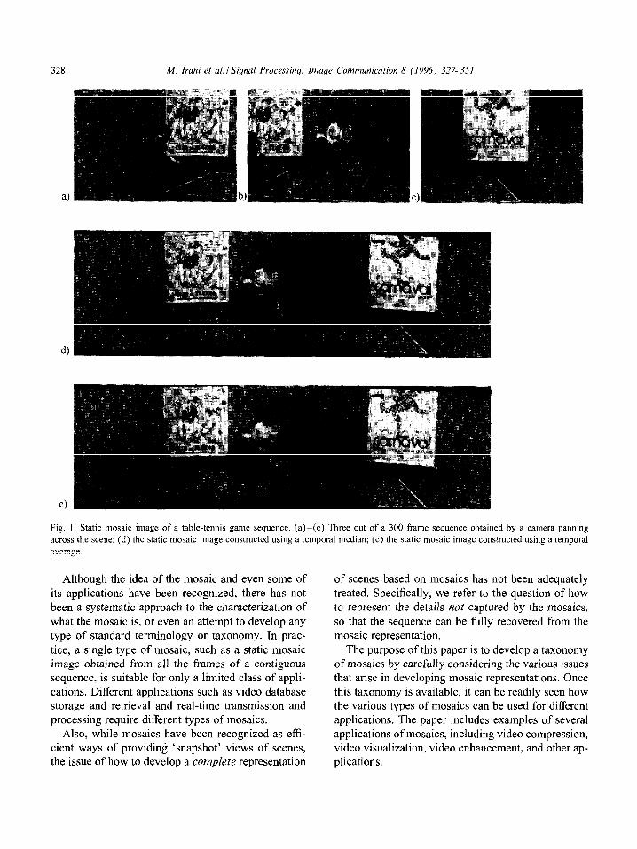
Fig. 1. Static mosaic image of a table-tennis game sequence. (a)-(c) Three out of a 300 frame sequence obtained by a camera panning
across the scene; (d) the static mosaic image constructed using a temporal median; (e) the static mosaic image constructed using a temporal
average.
Although the idea of the mosaic and even some of its applications have been recognized, there has not been a systematic approach to the characterization of what the mosaic is, or even an attempt to develop any type of standard terminology or taxonomy. In prac- tice, a single type of mosaic, such as a static mosaic image obtained from all the frames of a contiguous sequence, is suitable for only a limited class of appli- cations. Different applications such as video database storage and retrieval and real-time transmission and processing require different types of mosaics.
Also, while mosaics have been recognized as effi- cient ways of providing ‘snapshot’ views of scenes, the issue of how to develop a complete representation
of scenes based on mosaics has not been adequately treated. Specifically, we refer to the question of how to represent the details not captured by the mosaics, so that the sequence can be fully recovered from the mosaic representation.
The purpose of this paper is to develop a taxonomy of mosaics by carefully considering the various issues that arise in developing mosaic representations. Once this taxonomy is available, it can be readily seen how the various types of mosaics can be used for different applications. The paper includes examples of several applications of mosaics, including video compression, video visualization, video enhancement, and other ap- plications.
M. Iruni et al. ISiynul Prowssing: Image Communication 8 (1996) 327-351 329
The remainder of the paper is organized as follows.
Section 2 presents various types of mosaic represen- tations, and discusses their efficiency and complete- ness in terms of sequence representation. Section 3 describes the techniques that we use to align the im- ages, construct the mosaics, and detect the significant
‘residuals’ not captured in the mosaics from the input video stream. Section 4 outlines a number of powerful video applications of the mosaic representations with
examples and experimental results. Finally Section 5 discusses the salient issues for future research on this topic.
2. The mosaic representation
A mosaic image is constructed from all frames in a
scene sequence, giving a panoramic view of the scene. Although the idea of a mosaic image is simple and clear, a closer look at the definition reveals a number of subtle variations. For instance, since the different images that comprise a mosaic spatially overlap with each other, but are taken at different time instances,
there is a choice regarding how the different grey val- ues available for the same pixel are combined. Sim- ilarly, the variations in the pixel resolution between images leads to the issue of choosing the resolution of the mosaic image. Finally, there are also choices regarding the geometric transformation model used for aligning the images to each other. The different
choices in these various issues is typically a result of the type of application for which the mosaic is in- tended.
In this section we describe different ‘types’ of mosaics that arise out of the types of considerations outlined above.
2. I. Static mosaic
The static mosaic is the common mosaic represen- tation [ 17,22,2 1, 16, 141, although it is usually not re- ferred to by this name. It has been previously referred
to as mosaic or as ‘salient still’ (e.g., see Figs. 1 and 2). It will be shown (in Section 4) how the static mosaic can also be extended to represent temporal subsam- ples of key events in the sequence to produce a static ‘event’ mosaic (or ‘synopsis’ mosaic).
The input video sequence is usually segmented into
contiguous scene subsequences (e.g., see [23]), and a static mosaic image is constructed for each scene subsequence to provide a snapshot view of the sub- sequence. This is done in batch mode, by aligning all frames of that subsequence to a fixed coordinate
system (which can be either user-defined or chosen automatically according to some other criteria). The aligned images are then integrated using different types
of temporal filters into a mosaic image, and the signif- icant residuals are computed for each frame of relative to the mosaic image. The details of the mosaic con-
struction process are described in Section 3. Note that after integration, the moving objects either disappear or leave ‘ghost-like’ traces in the panoramic mosaic image.
Examples of static mosaic images are shown in Figs. 1 and 2. In Fig. 1 a static mosaic im- age of a table-tennis game sequence is constructed, once using a temporal median, and once using a temporal average. In this sequence, the player and the crowd move with respect to the back-
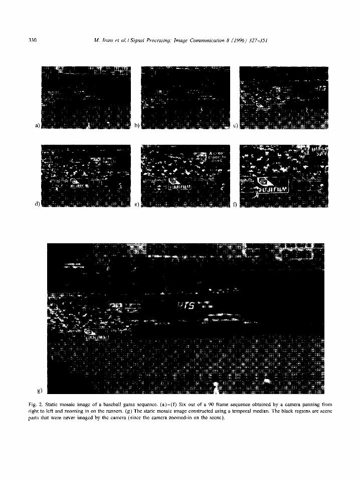
ground, while the camera pans to the right. The constructed mosaic image displays a sharp back- ground, with blurry crowd, and a ghost-like player. Fig. 2 shows a static mosaic image of a base- ball game sequence produced using a temporal median. In this sequence two players run across the field (from right to left), while the camera pans to the left and zooms in on the players. The constructed mosaic image in this case displays
a sharp image of the background with no trace of the two players. In both examples, a 2D mo- tion model was sufficient to align the images (see Section 3).
The static mosaic image exploits long term tempo- ral redundancies (over the entire scene subsequence) and large sputiul correlations (over large portions of the image frames), and is therefore an efficient scene representation. For examples, in Figs. 1 and 2, the entire video sequence can be represented by the mo- saic image of the background scene with the appropri- ate transformations that relate each frame to the mo-
saic image. The only information in the sequence not captured by the mosaic image and needing additional representation are the changes in the scene with re- spect to the background (e.g., moving players). These residuals can either be represented independently for
330 A4. Irani et al. ISignal Processing: Image Communication 8 (1996) 327-351
b)
e)
Fig. 2. Static mosaic image of a baseball game sequence. (a)-(f) S’ LX out of a 90 frame sequence obtained by a camera panning from
right to left and zooming in on the runners. (g) The static mosaic image constructed using a temporal median. The black regions are scene
parts that were never imaged by the camera (since the camera zoomed-in on the scene).
each frame, or can frequently be represented more ef- ficiently as another layer using yet another mosaic [l] (see Section 2.5).
The issue of representing residuals which are not captured by the mosaic image has frequently been overlooked by handling sequences with no scene ac- tivity [2 1, 16. 141. The mosaic image, along with the frame alignment transformations, and with the residu- als together constitute a conydrtr and &icirnt repre-
sentation, from which the video sequence can beJtl& reconstructed. These issues have been addressed to a limited extent with respect to video compression in [I], although that work does not consider how to as- sign a significance measure to the residuals or how to handle non-rigid layers.
The static mosaic, being an efficient scene repre- sentation, is ideal for video storuge and retrieval, es-
pecially for rupid browsing in large digital libraries
and to obtain efficient access to individual frames of interest. It can also be used to increase the efficiency of content-based indexing into a video sequence, to reduce the tedium associated with video manipulation
and analysis. Last but not least, it can be used for en- hanced visualization in the form of panoramic views, as well as a tool for enhancing the contents of the im- ages. These applications are described in greater detail in Section 4.
Since the stutic mosaic is constructed in hutch
mode, it cannot completely depict the dynamic as- pects of the video sequence. This requires a dynumic
mosaic, which is a srquerfcr of evolving mosaic im- ages, where the content of each new mosaic image is updated with the most current information from the most recent frame. The sequence of dynamic mosaics can be visualized either with a stationary background (e.g., by completely removing any camera induced motion), or in a manner such that each new mosaic image frame is aligned to the corresponding input video image frame. In the former case, the coordinate
system of the mosaic is fixed (see Fig. 3), whereas in the latter case the mosaic is viewed within a mov- ing coordinate system (see Fig. 4). In some cases a third alternative may be more appropriate, wherein a portion of the camera motion (e.g.. high frequency
jitter) is removed or a preferred camera trajectory is synthesized.
When a jxed coordinate system is chosen for the dynamic mosaic, each new image frame is warped to- wards the current dynamic mosaic image, and the in- formation within its field of view is updated accord- ing to the update criterion (e.g., most recent, average,
weighted average, etc. (see Section 3.2)). When the coordinate system of the mosaic is chosen to be (/J)-
namicall~~ updated to match that of the input sequence, the current dynamic mosaic image is warped towards each new frame, and then the information within the current field of view is updated according to the up- date criterion. When a virtuul coordinute sy.s/em is chosen (either predetermined by the user, or computed according to some criterion), both the dynamic mosaic
and the current frame are warped towards that coordi- nate system. Note that the definition of the coordinate system and the warping mechanism will vary accord- ing to the world and motion model (see Section 3).
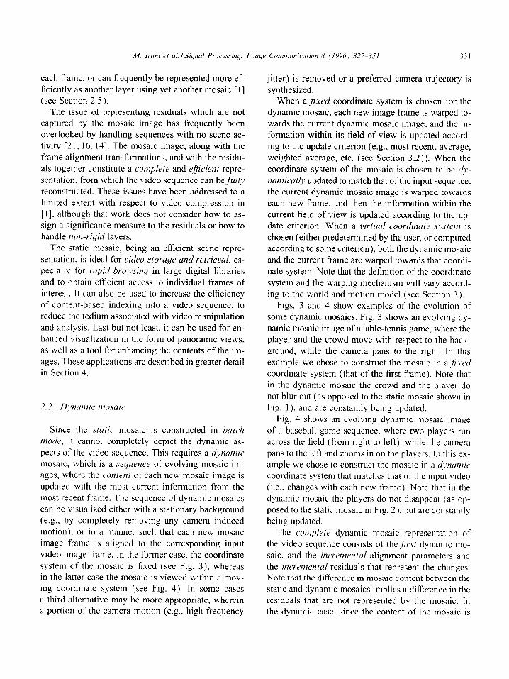
Figs. 3 and 4 show examples of the evolution of some dynamic mosaics. Fig. 3 shows an evolving dy-
namic mosaic image of a table-tennis game, where the player and the crowd move with respect to the back- ground, while the camera pans to the right. In this
example we chose to construct the mosaic in a ,~~.YcJc/ coordinate system (that of the first frame). Note that in the dynamic mosaic the crowd and the player do
not blur out (as opposed to the static mosaic shown in Fig. 1 ), and are constantly being updated.
Fig. 4 shows an evolving dynamic mosaic image of a baseball game sequence, where two players run across the field (from right to left), while the camera
pans to the left and zooms in on the players. In this ex- ample we chose to construct the mosaic in a dynumic
coordinate system that matches that of the input video (i.e., changes with each new frame). Note that in the
dynamic mosaic the players do not disappear (as op- posed to the static mosaic in Fig. 2), but are constantly being updated.
The umplete dynamic mosaic representation of the video sequence consists of the ,$r.st dynamic mo- saic, and the incrementul alignment parameters and
the incremental residuals that represent the changes. Note that the difference in mosaic content between the static and dynamic mosaics implies a difference in the residuals that are not represented by the mosaic. In the dynamic case, since the content of the mosaic is
332 M. Irani et al. /Signal Processing: Image Communication 8 (1996) 327-351
Fig. 3. Evolution of the dynamic mosaic images of the table-tennis game sequence. Left column: Three frames from the original sequence.
Right column: The corresponding dynamic mosaic images. Note that the position of the player and the crowd are constantly being updated
to match the current frame.
dynamically being updated, the residuals reflect only changes in the scene that occur in the time elapsed between successive frames, as well as additional parts of the scene that were revealed for the first time to the camera. These are different from the residuals in the
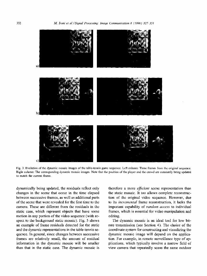
static case, which represent objects that have some motion in any portion of the video sequence (with re- spect to the background static mosaic). Fig. 5 shows an example of frame residuals detected for the static and the dynamic representations in the table-tennis se- quence. In general, since changes between successive frames are relatively small, the amount of residual information in the dynamic mosaic will be smaller than that in the static case. The dynamic mosaic is
therefore a more eficient scene representation than the static mosaic. It too allows complete reconstruc- tion of the original video sequence. However, due to its incremental frame reconstruction, it lacks the important capability of random access to individual
frames, which is essential for video manipulation and editing.
The dynamic mosaic is an ideal tool for low bit- rate transmission (see Section 4). The choice of the coordinate system for constructing and visualizing the dynamic mosaic image will depend on the applica- tion. For example, in remote surveillance type of ap- plications, which typically involve a narrow field of view camera that repeatedly scans the same outdoor

,2-i. Irani et al. ISignal Processiny: hnaye Communication 8 11996) 327-351 333
b)
Fig. 4. Evolution of the dynamic mosaic images of the baseball game sequence. Left column: Three frames from the original sequence.
Right column: The corresponding dynamic mosaic images. Note that the coordinate system as well as the position of the players are
constantly being updated to match the current frame.
M. Irani et al. ISignal Processing: Image Communication 8 (1996) 327-351
Fig. 5. The residual maps of static versus dynamic cases. (a) A single frame from the table-tennis sequence. (b) The residual map
computed for the corresponding frame in the static representation. The brighter values signify more significant residuals. (c) The residual
map computed for the corresponding frame in the dynamic representation. Note that the amount of residuals in the dynamic case is
significantly smaller than the amount of residuals in the static case.
natural scene and is usually very bouncy, it is benefi- cial to construct a dynamic mosaic with a fixed coor- dinate system, as it will also serve as a stabilization
mechanism for the remote observer. However, in flight surveillance, it makes more sense to keep a dynami- cally updating coordinate system that matches that of the view as seen by the pilot (with a gradually growing field of view obtained as the mosaic is constructed). These issues are discussed in Section 4.
2.3. Temporal pyramid
The static and the dynamic mosaics are extremes of a continuum: One uses a completely static image, which may be based on an arbitrarily long sequence, and in principle there may be an arbitrarily long time
interval between the current frame and the static mo- saic. The dynamic mosaic is completely current and always has the most recent available information. As a result, the dynamic mosaic is more efficient than the static mosaic, but since it requires sequential recon- struction of the frames, it does not provide as immedi- ate an access to the individual frames as the static mo-
saic. In order to bridge the gap between these two ex- tremes and obtain the benefits of both representations (i.e., representation efficiency versus random-access to frames), a ‘temporal pyramid’ mosaic can be used.
As discussed in Section 2.2, the static mosaic does not remove as much short-term temporal redundancy among residuals as the dynamic mosaic (see Fig. 5). The static mosaic can be extended to use a hierarchy of mosaics whose levels corresponds to different amounts of temporal integration. This hierarchical organization is similar to spatial image pyramid representation. The finest level contains the set of original images, one
for each frame of the input sequence. The temporal
sampling decreases successively as we go from fine to coarse resolution levels of the pyramid. We will refer
to the nodes of the pyramid as mosaics. For instance, in the manner analogous to the Laplacian pyramid, the sampling rate can be reduced by a factor of 2 between successive levels (although in principle, the factor can be any number). In this case, each mosaic at a given level can be obtained in the same fashion as pixel val- ues are computed in the Laplacian pyramid (e.g., as
difference of low-pass operators). The coarsest level will consist of a single mosaic, which is the same as the static mosaic described in Section 2.1. The suc- ceeding levels represent residuals estimated over var-
ious time scales. Reconstruction can be achieved by hierarchically combining the static mosaic with the residual mosaics, namely in logarithmic time.
2.4. Multiresolution mosaic
Changes in image resolution occur within the se- quence, e.g., as the camera zooms in and out. Con- structing the mosaic image in low resolution results
in the loss of high frequency information in the re- gions of the mosaic that correspond to high resolution frames. Constructing the mosaic image at the high- est detected resolution, on the other hand, incurs the penalty of oversampling the low resolution frames. Moreover, in the dynamic mosaic case, the resolution variation is not known in advance.
Varying image resolutions can be handled by a mul- tiresolution mosaic data structure, which captures in- formation from each new frame at its closest corre- sponding resolution level in a mosaic pyramid. It is a sparse pyramid in the sense that the resolution levels
M. Irani rt ul. I Signal Processing: haye Comrrwkution 8 (19%) 327-351 335
are not complete (certain mosaic regions may be rep- can be neglected. Similarly, if independent scene ac-
resented at high resolution, others only at low resolu- tivity is confined to a small number of pixels, again
tion). When a frame is predicted/reconstructed from these effects can be neglected during the construction
the mosaic pyramid, the highest existing resolution of the mosaic. In both these situations, there will be
data in the mosaic which corresponds to the frame nonzero but small residuals associated with the mo-
(i.e., is within its region of support) is projected onto saic. These residuals are represented separately. The
that frame’s resolution. 2D alignment process is described in Section 3.1.1.
Note that the multiresolution mosaic is a completely different representation than the temporal pyramid mo- saic, although both use a coarse-to-fine data structure. The unit elements at each level of the multiresolu- tion mosaic are pixrls, while the unit elements at each level of the temporal pyramid mosaic are mosuic im- ages. The multiresolution mosaic data structure can be applied to the static, dynamic, and temporal pyramid mosaic representations.
2.5.2. Purallux based mosaic
2.5. Mosaic wpresentutions C~YSUS scene complexity
As explained above, the 2D alignment models are sufficient when the effects of 3D parallax (relative to
the mosaic surface) are small. However, this does not mean that when these effects are significant, we need to abandon the mosaic-based approach to representing video sequences. One approach is to represent the par-
allax effects as indiiciduul frame residuals. A better and more efficient approach to modeling parallax effects can be done by naturally extending the mosaic repre- sentation to capture parallax in a single representation.
So far, we have described various types of mosaics that address different requirements, specifically rep- resentational efficiency and access efficiency. In this subsection, we consider another aspect of mosaic rep- resentations, namely the choice of the frame to frame alignment transformation.
2.5.1. T/w 20 mosuic All the examples that have been shown so far in
this paper have relied on constructing a mosaic image using 2D alignment parametric transformations. Such a mosaic provides a complete representation of the scene segment under the following circumstances: In scenarios where there is no scene activity apart from the motion of the camera and when either there is no translation of the camera, or when the entire scene can be approximated by a single parametric surface (typically a plane).
The key to the 3D extension lies in the observation that the residual motion after aligning a dominant pla-
nar surface in the scene is purely epipolar and is due to the combination of camera translation and the dis-
tance of the other parts of the scene from the dominant (aligned) plane [14, 191. Specifically, we use the fol- lowing result derived in [ 141: Given two views (under
perspective projection) of a scene (possibly from two distinct uncalibrated cameras), if the image motion corresponding to an arbitrary plane (called the ‘refer-
ence plane’) is compensated (by applying an appro- priate 2D parametric warping transformation to one
of the images) then the residual parallax displacement field on the reference image plane is an epipolar field. Further, the magnitude of the parallax displacement vector at each point directly depends on the distance of that point from the reference plane.
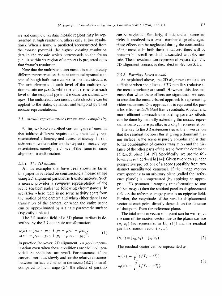
The 2D motion field of a 3D planar surface is de- scribed by the 2D quadratic transformation:
u(x) = 1’I.X + pz’ + p5 + p7x2 + psxy, c(x) == p3.r + Pd.,’ + p6 + p7xy + p*y2.
The total motion vector of a point can be written as the sum of the motion vector due to the planar surface
(u,, tip) (as represented in Eq. ( 1)) and the residual parallax motion vector (Us, rr):
In practice, however, 2D alignment is a good approx-
imation even when these conditions are violated, pro- vided the violations are small. For instances, if the camera translates slowly and/or the relative distances between surface elements in the scene (LIZ) is small compared to their range (Z), the effects of parallax
(u,L’) = (upcp) + (UbC,).
The residual vector can be represented as
(2)
(3)
336 M. Irani et al. ISignal Processing: Image Communication 8 (1996) 327-351
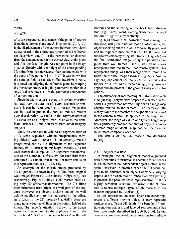
where
Y = HIP,,
H is the perpendicular distance of the point of interest from the reference plane and P, is its depth. (TX, TY, T,) is the displacement of the camera between two views
as expressed in the coordinate system of the reference (or fist) view, and Tl is the perpendicular distance from the camera center of the second view to the plane and f is the focal length. At each point in the image
y varies directly with the height of the corresponding 3D point from the reference surface and inversely with
the depth of the point. In [ 14,19,20] it was shown that the parallax field is a relative affine invariant. Finally, it is noted that aligning the reference plane by warping the inspection image using the parametric motion field (u,, vr) also removes all of the rotational components of camera motion.
Since the 3D structure is usually invariant over time (at least over the duration of several seconds or min-
utes), it can be represented as a mosaic image that can be used to predict the parallax-induced motion over that duration. We refer to this representation of
3D structure as a ‘height’ map (relative to the dom- inant surface), a term borrowed from aerial imagery analysis.
Thus, the complete mosaic-based representation of a 3D scene sequence (without independently mov- ing objects) would contain: (i) an intensity mosaic image produced by 3D alignment of the sequence frames, (ii) a corresponding height mosaic, (iii) for
each frame: the computed 2D alignment transforma- tion of the dominant surface, (iv) for each frame: the computed 3D camera translation. For more details on this representation see [14,13,15].
An example of the mosaic image produced by 3D alignment is shown in Fig. 6. The three original
wall images Frames l-3 are shown in Figs. 6(a)-(c) respectively. Fig. 6(d) shows a 2D mosaic built us-
ing only 2D affine transformations. The 2D affine transformations used aligns the wall part of the im- ages. However the objects sticking out of the wall exhibit parallax and are not registered by the affine. As a result in the 2D mosaic (Fig. 6(d)), there are many ghost (duplicate) lines in the bottom half of the image. The reader’s attention is drawn to the image regions corresponding to the duplicate lines in the boxes titled ‘TRY’ and ‘Wooden blocks’ in the left
bottom and the smearing on the book title informa-
tion (e.g., Excel, Word, Getting Started) in the right bottom of Fig. 6(d), respectively.
Fig. 6(e) shows a 3D corrected mosaic image. In this case, using the parallax motion information, the objects sticking out of the wall are correctly positioned
and no duplicate lines are visible. The 3D corrected mosaic was made by using wall frame 3 (Fig. 6(c)) as the final destination image. Using the parallax com- puted from wall frames 1 and 2, wall frame 2 was reprojected into the frame 3 coordinate system. This reprojected image was then merged with frame 3 to
make the Mosaic image shown in Fig. 6(e). Note in Fig. 6(c) one cannot see the boxes entitled ‘Wooden blocks’ or ‘TRY’. In the mosaic image, they however appear and are present in the geometrically correct lo- cations.
The efficiency of representing 3D information with a height map (heights with respect to a surface in the scene) is greater than representing it with a range map (depths relative to the camera). The increased effi-
ciency is due to the fact that the height map is invariant to the camera motion, as opposed to the range map. Moreover, the range of values of a typical height map has significantly smaller than that of a typical camera
centered range or ‘depth’ map, and can therefore be much more compactly encoded.
The details of the 3D mosaic are described
in [15].
2.5.3. Layers and tiles In principle, the 2D alignment model augmented
with 3D parallax information is adequate for all scenes in which there is no independent object motion in the scene. However, in practice, when the 3D scene be- gins to be cluttered with objects at widely varying
depths, and/or when real or ‘fence-like’ transparency is present, the parallax based representation of 3D is
highly inefficient. A natural extension to the 2D mo- saic is to use multiple layers of 2D mosaics in the manner suggested by Adelson [ 11.
In this representation, each layer can either rep- resent a different moving object or may represent surface at a different 3D depth. The benefits of mul- tiple motion analysis and layered representation has been previously described in [ 1 , 10,9,11,4]. In our own work, we have developed algorithms for multiple

Fig. 6. Parallax corrected mosaic to represent 3D scenes. (a)-(c) Three frames of the input video sequence taken from a sideways moving
camera. The third frame (c) is used as the reference image. (d) The result of constructing a mosaic-based on 2D planar surface alignment.
Patterns on the wall are perfectly aligned. However, note that objects ‘sticking out’ of the wall are not well aligned, as indicated by the
duplicate lines. (e) The result of constructing a mosaic after correcting for 3D planar parallax. Note that all portions of the scene are well
aligned.
motion segmentation [8] and layered motion recovery [ 181. We plan to combine these with the 2D mosaics, and the parallax-based representations described earlier.
Another extension that is necessary in order to han-
dle extended fields of view is a ‘tiled’ representation. To motivate this, consider the simple example of a panning camera. In this case, the use of a single mo- saic image plane based on central projection does not
meaningfully extend to more than a few degrees of ro- tation. Reprojecting the views acquired after rotating the camera by 45” or so results in significant distor- tion of the images, and therefore later in poor image reconstruction. Similarly when the camera is moved
around an object (e.g., even a simple object like a
box or a table) to get a frontal view of all of its sur- faces, projecting these to a single planar mosaic view will lead to the loss of image information from other views. In the panning case, a natural alternative is to use a coordinate system based on a spherical retina.
However, this approach does not easily generalize to the second example of a moving camera given above.
A better approach may be to have a series of tiles that correspond to different mosaic imaging planes (e.g., in the case of the pan, these will be tangent planes to the sphere) and assemble these ‘tiles’ together into a larger mosaic. Each image can be predicted from the tile that corresponds most to that image in terms of
338 M. Irani et al. ISignal Processing: Image Communication 8 (1996) 327-351
resolution and minimizes the distortion. In this way gions of interest (which is initially the entire image the representation becomes somewhat more complex, region) is used as a match measure. This measure is but its efficiency will be preserved while making it minimized with respect to the quadratic image motion more of a complete and effective scene representation. parameters.
The SSD error measure for estimating the image motion within a region is
3. Mosaic construction
A mosaic-based representation is constructed from
all frames in a scene sequence, giving a panoramic view of that scene. Three steps are involved in this process: the alignment of the images in the sequence, the integration of the images into a mosaic image, and
the computation of signficant residuals between the mosaic and the individual frames.
K(u)) = CU(x,t) --1(x - u(x),t - 1))2, (4) X
where x = (x, y) denotes the spatial image position of
a point, 1 the (Laplacian pyramid) image intensity and u(x) = (u(x, y), u(x, y)) denotes the image velocity at that point, and the sum is computed over all the points within the region and {u} is used to denote the entire
motion field within that region.
3.1. Image alignment
As noted in Eq. (1) (Section 2), the 2D motion field of a 3D planar surface can be described by the 2D quadratic transformation:
Image alignment depends on the chosen world model and motion model. The alignment can be lim- ited to 2D parametric motion models, or can utilize
more complex 3D motion models and layered repre- sentations. Most of the examples in this paper utilize 2D alignment models. In this section we describe the 2D alignment methods in some detail, and briefly outline the 3D alignment methods. More details of 3D alignment can be found in [ 14, 13, 151. This sec- tion also describes how we compose frame-to-frame alignment parameters to achieve the alignment of an
entire sequence of images.
u(x) = PIX + P2Y + Ps + P7X2 + PSXY,
o(x) = P3x + P4.Y + P6 + p7xY + pSY2.
(5)
Besides being a description of the instantaneous mo-
tion field of a planar surface, this transformation also describes well the 2D image motion of an arbitrary 3D scene undergoing camera rotations, zooms, and small camera translations, arrl, when the overall 3D range (Z) to the scene is much greater than the variation of the range within the scene (AZ).
3.1.1. 2D image alignment The parametric motion that is used to register
(align) images represents the motion of a domi- nant surface in the scene, usually the background scene. In the current implementation, 2D parametric motion models (a 6-parameter affine transforma- tion and an g-parameter quadratic transformation) are used to approximate the motions between two
images.
The objective function E given in Eq. (4) is mini- mized via the Gauss-Newton optimization technique. Let pi denote the current estimate of the quadratic
parameters. After warping the inspection image (to- wards the reference image) by applying the paramet- ric transformation pi to it, an incremental estimate Sp can be determined. After iterating certain number of times within a pyramid level, the process continues at the next finer level.
To align two images (an ‘inspection’ image and a ‘reference’ image), we use the hierarchical direct reg- istration technique described in [2,8] with a planar surface image motion model. This technique first con- structs a Laplacian pyramid from each of the two in- put images, and then estimates the motion parameters in a coarse-fine manner. Within each level the sum of squared difference (SSD) measure integrated over re-
With the above technique, the reference and inspec-
tion images are registered so that the desired image region is aligned. The above estimation technique is a least-squares based approach and hence possibly sen- sitive to outliers. However, as reported in [4] this sen- sitivity is minimized by doing the least-squares esti- mation over a pyramid. The pyramid based approach locks on to the dominant image motion in the scene.
We have also experimented and obtained good results with robust versions [ 1 l] of the above direct
M. lrani et al. I Signal Processiny: Image Communicution 8 (1996) 327-351 339
method. The robust version of the above method handles scenes with multiple moving objects. It com- putes the dominunt parametric motion, where all other image regions are detected as outliers [ 11, lo]. The outlier mask is used to segment the image region into the dominant layer (that whose image motion can be explained by the computed dominant 2D transfor- mation) and to the layer which corresponds to the re- maining parts of the image (whose motion cannot be explained by the computed 2D dominant parametric transformation; e.g., see Fig. 5). The same technique
can then be applied recursicely to the layer which corresponds to the remaining parts of the image, to find the next dominant parametric transformation and
its region within the image, etc. Note that the outlier mask computed for each 2D
transformation is a continuous mask. Its values can be used for ~r~eighting purposes in the robust parametric motion estimation. They are also occasionally used for weighting the pixels of the individual image frames during the irztegrution process to construct the mosaic
image (Section 3.2). Benefits of using these weights in the mosaic construction for some applications are demonstrated in Section 4.
technique described in [3]. The quasi-parametric
technique is generally more accurate than using optic flow, but requires an initial estimate for translation. If needed, an initial estimate of the translation direction can be obtained by using the optical flow obtained by using the technique also described in [3].
The sequential registration algorithm is useful when there is a visible planar surface in the scene that oc- cupies a significant portion of the image. However,
in many situations, such as images of curved objects and hilly terrains, no such plane may be present in
the scene, hence, the sequential registration algorithm may fail in the first step (of plane alignment). How- ever, the planefparallax representation is still appli-
cable, since a ‘virtual’ reference plane can be used as the basis for computing the residual parallax.
To handle the situations when a virtual plane is required, the planar surface alignment and the parallax estimation have to be performed simultaneously. This algorithm consists of two steps:
1. First the plane registration algorithm described in Section 3. I .l is applied to the entire scene. Al- though this may not register any real or virtual plane, it provides a good set of initial parameters for the second step.
3.1.2. 3Ddignment
Purulb.~ estimation. The key step involved in the computation of 3D alignment is the estimation of the residual parallax motion with respect to the refer- ence plane that is aligned by the 2D mosaic. The tech-
nique for achieving this is described in greater detail in [ 15, 131. Below we briefly outline our approach.
2. The total motion vector at a point is expressed as a sum of the motion vector due to a planar surface and the residual parallax motion. The initial esti- mate for the planar motion field is given by the re- sults of the first step given above. The parallax field is initialized to zero, and the translational motion parameters are set to an arbitrary initial value. Both these components are then refined simultaneously
The computation of the parallax information can proceed in one of two ways. The first technique takes a sequentid registrution approach, in which the plane is first registered using an 8 parameter quadratic trans- formation. The residual parallax is then estimated as a separate step. The second technique simultaneously estimates the planar and parallax motion compo- nents, and is hence referred to as a simultuneous registration.
_ i.e., the 8 parameters of the quadratic transfor- mation is refined as well as the translational mo- tion parameters and the parallax magnitude at each pixel.
The refinement process achieves alignment of every pixel (within the region where the two views overlap) between the two views. The refinement process is done in a manner similar to the quasi-parametric ego motion estimation algorithm described in [3].
In the sequential approach, the plane registration 30 corrected mosuics. We refer to the mosaic image is achieved in the same manner as described in Sec- that is obtained by achieving 3D alignment between tion 3.1.1. After the plane is aligned in this fashion, multiple views as the ‘3D corrected mosaic’. The re- the parallax vectors and the direction of translation are covery of parallax information requires at least two simultaneously estimated using the quasi-parametric views of the same portion of the scene. This means
340 M. Irani et al. ISignal Processing: Image Communication 8 (1996) 327-351
that the extension of a single view into a mosaic con- sisting of information from a second view requires a third view to provide the parallax information for the second view (in particular, for those portions of the second view not visible in the first view). The three views should partially (but not completely) overlap
with each other. Given such views, the process of con- struction involves the following steps: The first step
is to register the first two images and to build a par- allax map in the second frame’s coordinate system. With this parallax map, we compute the quadratic transformation parameters (pi,. . . , ~8) and the cam-
era translation parameters (Ta, TzY, Tzz), which regis- ter the second image with the third image. Note that to estimate these 11 ‘pose’ parameters in the mosaic case, we do not need point correspondences. Rather, we directly register the second image with the third
image using the estimated parallax map as an input. We again minimize Eq. (4) but this time estimate only
the 11 pose parameters.
to obtain the alignment parameters between any two frames of the sequence.
When constructing a static mosaic, all the frames are aligned to a fixed coordinate system. If the mo- saic coordinate system that is selected is that of a par- ticular frame (called the ‘reference’ frame), then all
other images are aligned to that frame. If a virtual coordinate system is selected, then the transformation between the virtual coordinate system and one of the
input frames (the reference frame) needs to be given. In this case, this additional transformation is simply
composed with the transformations required to align each frame to the reference frame.
Note that the sequence alignment process requires only one pass on the sequence (for computing adja- cent alignment transformations, and then sequentially composing these transformations for warping the im-
age frames to the mosaic coordinate system).
After the pose parameters between the second and the third image are estimated, the second image is
then reprojected (by forward warping) to create a syn- thetic image taken from the third view-point. This
synthetic image however contains image regions com- mon to the first two images but not present in the third image. The final step to obtain the mosaic is to merge the synthetic third image with the actual third image. The result of this process of construct- ing the 3D corrected mosaic was previously shown in
Fig. 6.
Frame to mosaic. One problem with frame to frame alignment is that errors may accumulate during the repeated composition of alignment parameters. The alignment can be further refined by directly refining the transformation between each image frame and the mosaic image. To handle the problem of large dis- placements between the mosaic image and the new image frames, the alignment parameters computed between the previous frame and the mosaic image are used as an initial estimate.
To construct the parallax mosaic, we forward warp the parallax map to the third image coordinate system, much the same way as the second image was repro- jetted. Given the pose parameters between images 2 and 3, the parallax map of those portions not visible in 1 but only in 2 and 3 can also be estimated. The re-
projected parallax map is merged with this additional parallax information to complete the mosaic.
3.1.3. Sequence alignment The alignment of all image frames in the sequence
to form the mosaic can be performed in three ways:
Mosaic to frame. The frame to mosaic alignment is appropriate when the mosaic is constructed with respect to a static coordinate system. However, in some dynamic applications such as real-time video transmission, it is important to maintain the images in their input coordinate systems. In this case, it is more useful to align the mosaic to the current frame. In this case the transformation between the most recent mosaic and the current frame is identical to the transformation between the previous frame and the new frame.
3.2. Image integration
Frame to frame. The alignment parameters are first Once the frames are aligned (or, in the dynamic computed between successive frames for the entire case, the current mosaic and new frame are aligned), sequence. These parameters can then be composed they can be integrated to construct the mosaic
M. Irani et al. ISignal Processing: Image Communication 8 (1996) 327-351 341
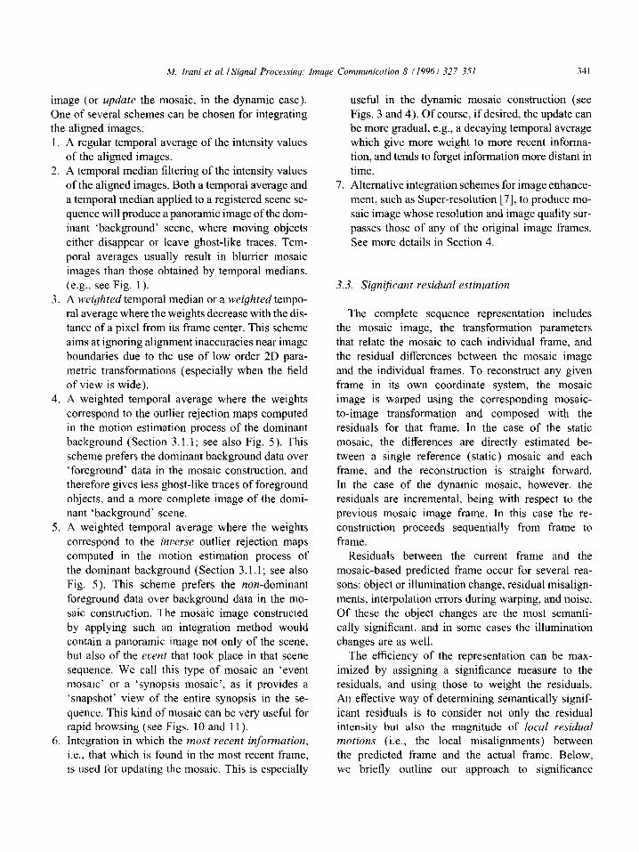
image (or update the mosaic, in the dynamic case). One of several schemes can be chosen for integrating the aligned images: 1. A regular temporal average of the intensity values
of the aligned images. 2. A temporal median filtering of the intensity values
of the aligned images. Both a temporal average and
a temporal median applied to a registered scene se- quence will produce a panoramic image of the dom- inant ‘background’ scene, where moving objects
either disappear or leave ghost-like traces. Tem- poral averages usually result in blurrier mosaic images than those obtained by temporal medians.
(e.g., see Fig. 1). 3. A w*eigh ted temporal median or a weigh ted tempo-
ral average where the weights decrease with the dis- tance of a pixel from its frame center. This scheme
aims at ignoring alignment inaccuracies near image boundaries due to the use of low order 2D para- metric transformations (especially when the field of view is wide).
4. A weighted temporal average where the weights correspond to the outlier rejection maps computed in the motion estimation process of the dominant background (Section 3.1.1; see also Fig. 5). This scheme prefers the dominant background data over ‘foreground’ data in the mosaic construction, and therefore gives less ghost-like traces of foreground objects, and a more complete image of the domi- nant ‘background’ scene.
5. A weighted temporal average where the weights correspond to the inverse outlier rejection maps computed in the motion estimation process of the dominant background (Section 3.1.1; see also
Fig. 5). This scheme prefers the non-dominant foreground data over background data in the mo- saic construction. The mosaic image constructed
by applying such an integration method would contain a panoramic image not only of the scene, but also of the eaent that took place in that scene sequence. We call this type of mosaic an ‘event mosaic’ or a ‘synopsis mosaic’, as it provides a ‘snapshot’ view of the entire synopsis in the se-
quence. This kind of mosaic can be very useful for rapid browsing (see Figs. 10 and 11).
6. Integration in which the most recent information,
i.e., that which is found in the most recent frame, is used for updating the mosaic. This is especially
useful in the dynamic mosaic construction (see Figs. 3 and 4). Of course, if desired, the update can be more gradual, e.g., a decaying temporal average which give more weight to more recent informa- tion, and tends to forget information more distant in
time. 7. Alternative integration schemes for image enhance-
ment, such as Super-resolution [7], to produce mo- saic image whose resolution and image quality sur-
passes those of any of the original image frames. See more details in Section 4.
3.3. Significant residual estimation
The complete sequence representation includes the mosaic image, the transformation parameters that relate the mosaic to each individual frame, and
the residual differences between the mosaic image and the individual frames. To reconstruct any given frame in its own coordinate system, the mosaic
image is warped using the corresponding mosaic- to-image transformation and composed with the residuals for that frame. In the case of the static mosaic, the differences are directly estimated be-
tween a single reference (static) mosaic and each frame, and the reconstruction is straight forward. In the case of the dynamic mosaic, however, the
residuals are incremental, being with respect to the previous mosaic image frame. In this case the re- construction proceeds sequentially from frame to frame.
Residuals between the current frame and the
mosaic-based predicted frame occur for several rea- sons: object or illumination change, residual misalign- ments, interpolation errors during warping, and noise.
Of these the object changes are the most semanti- cally significant, and in some cases the illumination changes are as well.
The efficiency of the representation can be max-
imized by assigning a significance measure to the residuals, and using those to weight the residuals. An effective way of determining semantically signif-
icant residuals is to consider not only the residual intensity but also the magnitude of local residual motions (i.e., the local misalignments) between the predicted frame and the actual frame. Below, we briefly outline our approach to significance
342 M. Irani et al. ISignal Processing: Image Communication 8 (1996) 327-351
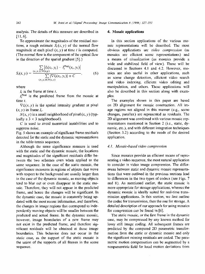
analysis. The details of this measure are described in
[ll, 61. To approximate the magnitudes of the residual mo-
tions, a rough estimate S, (x, y) of the normal flow magnitude at each pixel (x, y) at time t is computed.
(The normal flow is the component of the optical flow in the direction of the spatial gradient [5].)
C Id(Xi, Vi) - Ip”“(Xi, Vi>1
where It is the frame at time ZPred
t. VIt(x,y) is the spatial intensity gradient at pixel
(x, y ) in frame 1,. N(x, y) is a small neighborhood of pixel (x, y) (typ-
ically a 3 x 3 neighborhood). C is used to avoid numerical instabilities and to
suppress noise. Fig. 5 shows an example of significant frame residuals detected for the static and the dynamic representations
in the table-tennis sequence. Although the same significance measure is used
with the static and the dynamic mosaic, the locations and magnitudes of the significant residuals differ be- tween the two schemes even when applied to the
same sequence. In the case of the static mosaic, the significance measures in regions of objects that move
with respect to the background are usually larger than in the case of the dynamic mosaic, as moving objects tend to blur out or even disappear in the static mo- saic. Therefore, they will not appear in the predicted frame, and hence the changes will be significant. In the dynamic case, the mosaic is constantly being up- dated with the most recent information, and therefore,
the changes in image regions that correspond to inde- pendently moving objects will be smaller between the predicted and actual frame. In the dynamic mosaic, however, image boundaries of a new frame may not exist in the predicted frame, and therefore sig- nificant residuals will be obtained at those image boundaries. This behavior does not occur in the static case, as the support of the static mosaic is the union of the supports of all frames in the scene sequence.
4. Mosaic applications
In this section applications of the various mo- saic representations will be described. The most
obvious applications are video compression (as mosaics are efficient scene representations) and
a means of visualization (as mosaics provide a wide and stabilized field of view). These will be discussed in Sections 4.1 and 4.2. However, mo- saics are also useful in other applications, such as scene change detection, efficient video search and video indexing, efficient video editing and manipulation, and others. These applications will also be described in this section along with exam-
ples. The examples shown in this paper are based
on 2D alignment for mosaic construction. All im-
age regions not aligned in this manner (e.g., scene changes, parallax) are represented as residuals. The 2D alignment was combined with various mosaic rep- resentations mentioned in Section 2 (i.e., static, dy- namic, etc.), and with different integration techniques (Section 3.2) according to the needs of the desired application.
4.1. Mosaic-based video compression
Since mosaics provide an efficient means of repre- senting a video sequence, the most natural application to consider is video image compression. The differ-
ences between static and dynamic mosaic representa- tions that were outlined in the previous sections lead to differences in the two types of codecs (see Figs. 7 and 8). As mentioned earlier, the static mosaic is more appropriate for storage applications, whereas the dynamic mosaic is ideally suited for real-time trans- mission applications. In this section, we first outline the codec for transmission, then the one for storage. A detailed description of our approach for using mosaics
for compression can be found in [6]. The static mosaic, or the first frame in the dynamic
case, may be compressed by any known method for lossy still image coding. All subsequent frames are predicted by the computed 2D parametric transfor- mation from the static or dynamic mosaic and only the significant missing residuals are coded. The para- metric motion compensation can be augmented by a nonparametric field for local motion deviations from
hf. Irani et ul. ISignul Processiny: Imugr Cmnrnunicutior~ 8 11996) 327 351 343
Mosaics CODER
Align 4’ successive -
Residual Significance
frames Estimation * analysis
- . . . . . . . . . . . . . . . . . . .
. . . . . . . . . . . . . . . . . . . . . . .,,fZZODER . . . . . . . . . . . . . . . . . . .
. . . . . . . . . . . . . . . . . . . . . . . . . . . . . . . . . . . . . . . . . . . . . 9 . . . . .
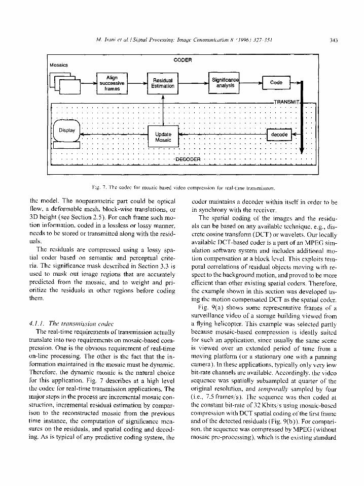
Fig. 7. The codec for mosaic-based video compression for real-time transmission
the model. The nonparametric part could be optical
flow, a deformable mesh, block-wise translations, or 3D height (see Section 2.5). For each frame such mo- tion information, coded in a lossless or lossy manner, needs to be stored or transmitted along with the resid- uals.
The residuals are compressed using a lossy spa- tial coder based on semantic and perceptual crite-
ria. The significance mask described in Section 3.3 is used to mask out image regions that are accurately predicted from the mosaic, and to weight and pri-
oritize the residuals in other regions before coding them.
4. I. 1. The transmission CO&Y The real-time requirements of transmission actually
translate into two requirements on mosaic-based com-
pression. One is the obvious requirement of real-time on-line processing. The other is the fact that the in- formation maintained in the mosaic must be dynamic. Therefore, the dynamic mosaic is the natural choice for this application. Fig. 7 describes at a high level
the codec for real-time transmission applications. The major steps in the process are incremental mosaic con-
struction, incremental residual estimation by compar- ison to the reconstructed mosaic from the previous time instance, the computation of significance mea- sures on the residuals, and spatial coding and decod- ing. As is typical of any predictive coding system, the
coder maintains a decoder within itself in order to be
in synchrony with the receiver. The spatial coding of the images and the residu-
als can be based on any available technique, e.g., dis- crete cosine transform (DCT) or wavelets. Our locally available DCT-based coder is a part of an MPEG sim- ulation software system and includes additional mo-
tion compensation at a block level. This exploits tem- poral correlations of residual objects moving with re- spect to the background motion, and proved to be more efficient than other existing spatial coders. Therefore,
the example shown in this section was developed us- ing the motion compensated DCT as the spatial coder.
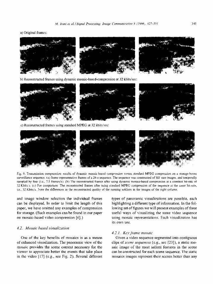
Fig. 9(a) shows some representative frames of a surveillance video of a storage building viewed from a flying helicopter. This example was selected partly because mosaic-based compression is ideally suited for such an application, since usually the same scene is viewed over an extended period of time from a
moving platform (or a stationary one with a panning camera). In these applications, typically only very low bit-rate channels are available. Accordingly, the video sequence was spatially subsampled at quarter of the original resolution, and temporull~~ sampled by four
(i.e., 7.5 frames/s). The sequence was then coded at the constant bit-rate of 32 Kbits/‘s using mosaic-based compression with DCT spatial coding of the first frame and of the detected residuals (Fig. 9(b)). For compari- son, the sequence was compressed by MPEG (without mosaic pre-processing), which is the existing standard
344 M. Irani et al. ISignal Processing: Image Communication 8 (1996) 327-351
STORAGE
Fl
image sequence
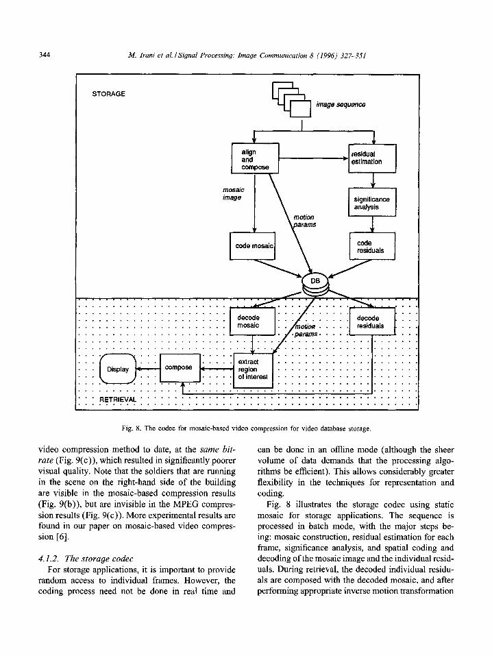
Fig. 8. The codec for mosaic-based video compression for video database storage.
video compression method to date, at the same bit- rate (Fig. 9(c)), which resulted in significantly poorer visual quality. Note that the soldiers that are running
in the scene on the right-hand side of the building are visible in the mosaic-based compression results
(Fig. 9(b)), but are invisible in the MPEG compres- sion results (Fig. 9(c)). More experimental results are found in our paper on mosaic-based video compres- sion [6].
4.1.2. The storage codec For storage applications, it is important to provide
random access to individual frames. However, the coding process need not be done in real time and
can be done in an offline mode (although the sheer volume of data demands that the processing algo- rithms be efficient). This allows considerably greater flexibility in the techniques for representation and coding.
Fig. 8 illustrates the storage codec using static mosaic for storage applications. The sequence is processed in batch mode, with the major steps be- ing: mosaic construction, residual estimation for each frame, significance analysis, and spatial coding and decoding of the mosaic image and the individual resid- uals. During retrieval, the decoded individual residu- als are composed with the decoded mosaic, and after performing appropriate inverse motion transformation
&I. Irani et al. I Signal Processing: Image Communication 8 (1996) 327-351 335
b) Reconstructed frames using dynamic mosaic-based-compression at 32 kbitsisec.
c) Reconstructed frames using standard MPEG at 32 kbits/sec:
Fig. 9. Transmission compression: results of dynamic mosaic-based compression versus standard MPEG compression on a storage-house
surveillance sequence. (a) Some representative frames of a 24-s sequence. The sequence was constructed of SIF size images, and temporally
sampled by four (i.e., 7.5 frames/s). (b) The reconstructed frames after using dynamic mosaic-based compression at a constant bit-rate of
32 Kbits:s. (c) For comparison: The reconstructed frames after using standard MPEG compression of the sequence at the same bit-rate,
i.e., 32 Kbits/s. Note the differences in the reconstructed quality of the running soldiers in the images of the right column.
and image window selection the individual frames
can be displayed. In order to limit the length of this paper, we have omitted any examples of compression for storage. (Such examples can be found in our paper on mosaic-based video compression [6].)
types of panoramic visualizations are possible, each highlighting a different type of information. In the fol- lowing set of figures we will present examples of three useful ways of visualizing the same video sequence using mosaic representations. Each visualization has its own use.
4.2. Gsualkation
One of the key benefits of mosaics is as a means of enhanced visualization. The panoramic view of the mosaic provides the scene context necessary for the viewer to appreciate better the events that take place in the video [17] (e.g., see Fig. 2). Several different
4.2.1. Key jiame mosaic Given a video sequence segmented into contiguous
clips of scene sequences (e.g., see [23]), a static mo- saic image of the most salient features in the scene can be constructed for each scene sequence. The static mosaics images represent their scenes better than any
346 M. Irani et al. ISignal Processing: Image Communication 8 (1996) 327-3.51
single frame, and can therefore be used as key frames for rapid browsing through the entire video sequence
[22], which is digitally stored, and for other purposes as well (see Section 4.4). The panoramic visualization shown of the baseball sequence shown in Fig. 2(g)
also illustrates the idea of the key frame mosaic. A second example of a key frame mosaic is
shown in Fig. 10(g). This figure displays a back- ground a 12-second a
camera a helicopter.
a synopsis a
mosaic
a static
a new a sequence
a virtual
a virtual
a desired
3 and 4 show
a display
[ 171.
a useful
a se-
a framestore
a single
a sequence a deserted a re-

Fig. IO. Panoramic mosaic Image of a scene captured by a 12-s flight sequence. (a)-(f) SIX frames sampled out of the 360 frame
sequence. Note the two lrnaged helicopters in the foreground. (g) The panoramic mosaic image of the hnc~k~lro~~d scene (without the two
imaged helicopters). (h) The synopsis mosaic image of the sequence showing the trajectories of the two imaged helicopters on top of the
background mosaic.
n/r. Irani et al. /Signal Processing: Image Communication 8 (1994) 327-351
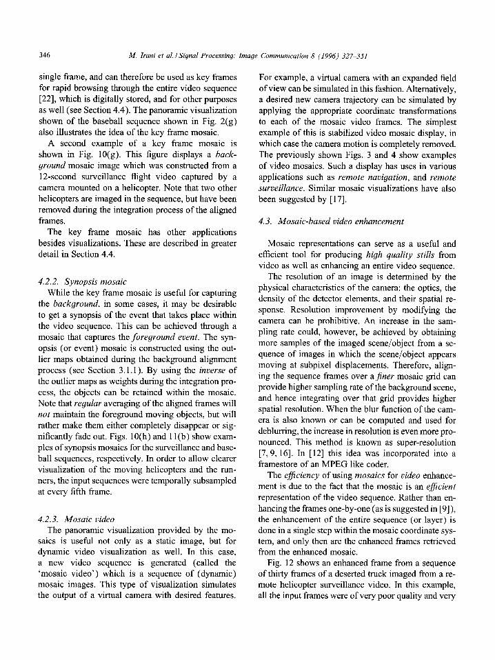
Fig. 11. Synopsis mosaic image of the baseball game sequence. (a) The static background mosaic of the scene without the event. (b) The
synopsis mosaic of the baseball sequence showing the event that occurred in the scene on top of the background mosaic (i.e., showing
the trajectories of the two runners).
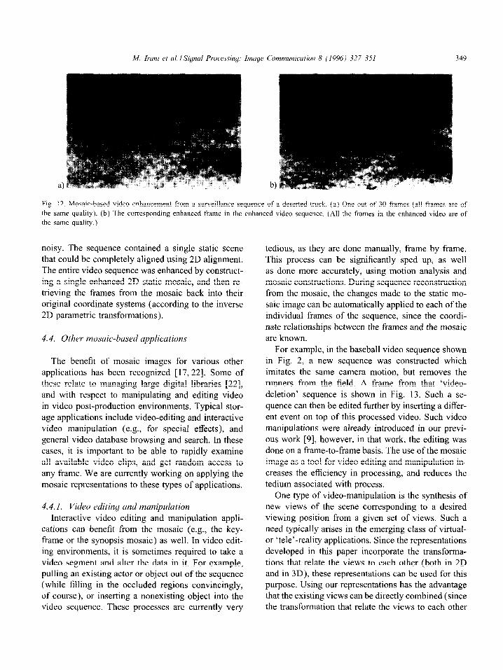
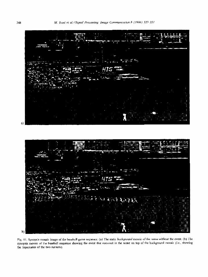
Fig. 12. Mosaic-based video enhancement from a surveillance sequence of a deserted truck. (a) One out of 30 frames (all frames are of
the same quality). (b) The corresponding enhanced frame in the enhanced video sequence. (All the frames in the enhanced video are of
the same quality.)
noisy. The sequence contained a single static scene
that could be completely aligned using 2D alignment. The entire video sequence was enhanced by construct- ing a single enhanced 2D static mosaic, and then re- trieving the frames from the mosaic back into their original coordinate systems (according to the inverse 2D parametric transformations).
4.4. Other mosuic-based upplications
The benefit of mosaic images for various other applications has been recognized [17,22]. Some of these relate to managing large digital libraries [22],
and with respect to manipulating and editing video in video post-production environments. Typical stor- age applications include video-editing and interactive video manipulation (e.g., for special effects), and
general video database browsing and search. In these cases, it is important to be able to rapidly examine all available video clips, and get random access to any frame. We are currently working on applying the mosaic representations to these types of applications.
4.4.1. Video editing and manipulation
Interactive video editing and manipulation appli- cations can benefit from the mosaic (e.g., the key- frame or the synopsis mosaic) as well. In video edit- ing environments, it is sometimes required to take a
video segment and alter the data in it. For example, pulling an existing actor or object out of the sequence (while filling in the occluded regions convincingly, of course), or inserting a nonexisting object into the video sequence. These processes are currently very
tedious, as they are done manually, frame by frame. This process can be significantly sped up, as well as done more accurately, using motion analysis and mosaic constructions. During sequence reconstruction from the mosaic, the changes made to the static mo- saic image can be automatically applied to each of the
individual frames of the sequence, since the coordi- nate relationships between the frames and the mosaic are known.
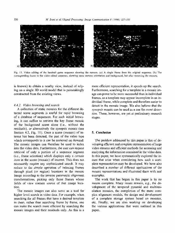
For example, in the baseball video sequence shown in Fig. 2, a new sequence was constructed which imitates the same camera motion, but removes the
runners from the field. A frame from that ‘video- deletion’ sequence is shown in Fig. 13. Such a se- quence can then be edited further by inserting a differ- ent event on top of this processed video. Such video manipulations were already introduced in our previ-
ous work [9], however, in that work, the editing was done on a frame-to-frame basis. The use of the mosaic image as a tool for video editing and manipulation in- creases the efficiency in processing, and reduces the tedium associated with process.
One type of video-manipulation is the synthesis of new views of the scene corresponding to a desired viewing position from a given set of views. Such a need typically arises in the emerging class of virtual- or ‘tele’-reality applications. Since the representations developed in this paper incorporate the transforma-
tions that relate the views to each other (both in 2D and in 3D), these representations can be used for this purpose. Using our representations has the advantage that the existing views can be directly combined (since the transformation that relate the views to each other
hf. Irani et al. /Signal Processing: Image Communication 8 (1996) 327-351
Fig. 13. Video editing of the baseball game sequence showing the runners. (a) A single frame from the original sequence. (b) The
corresponding frame in the video edited sequence, showing same camera orientation and background, but after removing the runners.
is known) to obtain a nearby view, ing on a single 3D world model that
constructed from the existing views.
4.4.2. Video browsing and search
instead of rely- is painstakingly
A collection of static mosaics for the different de-
tected scene segments is useful for rapid browsing of a database of sequences. For such initial brows- ing, it can suffice to retrieve the key frame mosaic of the background scene alone (i.e., without the
residuals), or alternatively the synopsis mosaic (see Section 4.2, Fig. 11). Once a scene (mosaic) of in- terest has been detected, the part of the video tape which corresponds to it can be retrieved on demand. The mosaic images can therefore be used to index into the video data. Furthermore, the user can request
retrieval of only a portion of a sequence segment (i.e., frame selection) which displays only a certain
item in the scene (mosaic) of interest. This does not necessarily require any sophisticated search. It may reduce to the simple operation of indexing frames through pixel (or region) locations in the mosaic image according to the inverse parametric alignment
transformations, picking only those frames whose fields of view contain source of that image loca- tion.
The mosaic images can also serve as a tool for higher level search in video data. For example, when searching for all frames that have a desired template in them, rather than searching frame by frame, one can make the search more efficient by searching the mosaic images and their residuals only. As this is a
more efficient representation, it speeds up the search.
Furthermore, searching for a template in a mosaic im- age can prove to be more successful than in individual frames, as a template may appear incomplete in an in- dividual frame, while complete and therefore easier to detect in the mosaic image. We also believe that the
synopsis mosaic can be used as a cue for event detec-
tion. These, however, are yet at preliminary research stages.
5. Conclusion
The problem addressed by this paper is that of de- veloping efficient and complete representation of large video streams and efficient methods for accessing and
analyzing the information contained in the video data. In this paper, we have systematically explored the is- sues that arise when considering how such a com- plete representation may be developed. We have also described a number of different applications of the mosaic representations and illustrated them with real examples.
The work that has begun in this paper is by no means complete. Many issues remain, e.g., the de- velopment of the temporal pyramid and multires- olution mosaics, the completion of the more com- plex alignment models, the design and development of a complete storage system based on mosaics, etc. Finally, we are also working on developing the various applications that were outlined in this paper.
M. Iruni et al. ISignal Processing: Imuqe Communiccrtion 8 119%) 327 3.51 351
References
[I] E.H. Adelson, Layered representations for image coding,
Tech. Report 181, MIT Media Lab. Vision and Modeling
Group, December I99
Cott7pur. Vision Graph. Image Process.:
Gruphtd Models and ImugL’ Processing, Vol. 53, May
1991, pp. 231-239.
[8] M. lrani and S. Peleg. “Image sequence enhancement using
multiple motion analysis”, Proc. IEEE Cot$ on Computer
C ision und Partern Rrwgnition, June 1992.
[9] M. Iram and S. Peleg, “Using motion analysis for image
enhancement”, J. Vi.suul Comtn. Imuge Representation.
Vol. 4, No. 4, December 1993, pp. 324-335.
[IO] M. Irani, B. Rousso and S. Peleg, “Detecting and tracking
multiple moving objects using temporal integration”, Proc.
European Con/. on Computer Vision, Santa Margarita
Ligure, May 1992. pp. 282-287.
[I I] M. Irani, B. Rousso and S. Peleg, “Computing occluding
and transparent motions”, Internut. J. Comput Vi.Gon,
Vol. 12, February 1994, pp. 5-16.
[I21 R. Kermode, Building the big picture: Enhanced resolution
from coding, MSc thesis, MIT. June 1994.
[13] R. Kumar, P. Anandan and K. Hanna. “Direct recovery
of shape from multiple views: a parallax based approach”,
Proc,. 12112 ICPR, 1994.
[ 141 R. Kumar, P. Anandan and K. Hanna, “Shape recovery from
multiple views: A parallax based approach”, DARPA IL’
Workshop, Monterey. CA, November 1994.
[ 151 R. Kumar, P. Anandan, M. Irani. J.R. Bergen and K.J.
Hanna, “Representation of scenes from collections of
images”, Wotkshop on ReprPsmrrrtiotts of’ Visual Swnes,
1995.
[I61 S. Mann and R.W. Picard, “Virtual bellows: Constructing
high quality stills from video”, Ptw. IEEE fntwnrtt. C’onj:
on Image Prowsitug, November 1994.
[I71 P.C. McLean, Structured video coding. MSc thesis, MIT,
June 1991.
[ 181 S. Peleg, S. Hsu and P. Anandan, “Accurate computation of
optical flow by using layered motion representations”. Proc
ICPRY4. 1994.
[ 191 H. Sawhney, 3d geometry from planar parallax. Pro<, CIVPR
YZ. June 1994.
[20] A. Shashua and N. Navab, “Relative affine structure: Theory
and application to 3d reconstruction from perspective views”,
Proc. IEEE Conf: on Computer Vision and Puttern
Recognition, Seattle, WA., June 1994, pp. 483-489.
[2l] R. Sreliski, Image mosaicing for tele-reality applications.
Tech. Report CRL 9412, Dlgital Equipment Corporation,
1994.
[22] L. Teodosio and W. Bender, “Salient video stills: Content
and context preserved”, ACM Multimetliu ‘93, Submitted.
[23] H.-J. Zhang, A. Kankanhalli and S.W. Smoliar, “Automatic
partitioning of full-motion video”. ~2lullimmdia .S~xtem.s.
Vol. I, No. I. 1993, pp. 10-28.
Related Documents