Photon Netw Commun (2010) 19:22–31 DOI 10.1007/s11107-009-0207-9 Efficient optimization of network protection design with p-cycles Hoang N. Nguyen · Daryoush Habibi · Quoc V. Phung Received: 4 April 2009 / Accepted: 9 August 2009 / Published online: 3 September 2009 © Springer Science+Business Media, LLC 2009 Abstract The purpose of this paper is to consider network survivability designs that utilize the p-cycle, and to propose a novel ILP formulation for capacity design based on network fundamental cycles, as well as the available straddling links. Concepts of visible and hidden straddling links—which are essential components of the model presented herein—are also introduced. The proposed model caters for the case of joint optimization of a p-cycle network that can be solved without enumerating p-cycle candidates. In addition, the complexity of the proposed model is much less than any con- ventional model dealing with large size networks and suit- able for the design of networks having multiple quality of protection (MQoP) service classes using mixed protection techniques. Keywords Network survivability · p-cycle 1 Introduction and motivation The introduction of p-cycles into network protection and survivability design in 1998 by W. D. Grover et al. [1] has advanced the field to a new level, and has success- fully filled the disparities in resource efficiency and recovery time between mesh and ring networks. The p-cycle can be considered as the most efficient pre-configured protection for networks. With restoration speeds comparable to that of H. N. Nguyen (B ) · D. Habibi · Q. V. Phung School of Engineering, Edith Cowan University, Perth, Australia e-mail: [email protected] D. Habibi e-mail: [email protected] Q. V. Phung e-mail: [email protected] ring topologies, and capacity efficiency akin to that of mesh networks, the protection scheme is implemented onto virtual ring structure segments of a mesh network. In addition, the p-cycle takes advantage of straddling links to achieve further resource utilization. Figure 1 is a example of a p-cycle. Here, the thick solid lines show spare channels that protect the working channels passing through them, whereas the dashed lines depict the straddling spans which require no spare capacity, but can be protected twice the number of working channels passing through them. Although, the p-cycle is an advanced pre- configured protection scheme, its capacity allocation model (known as the pure ILP model )[2] employs all possible can- didates. The number of p-cycle candidates increases expo- nentially with network size, and also with the complexity of the ILP model. The pure ILP model usually does not take into account the ‘non-simple p-cycle’ as its inclusion may result in the number of candidates increasing significantly. In this case, the results obtained from the model are not optimal, as the extra straddling relationships with non-simple p-cycles will not be included in the solution. This study aims to support the design of networks that provide MQoP service classes [3] and applying mixed pro- tection techniques in one model [4]. For this purpose, various protection techniques are integrated into one ILP formula- tion, giving due consideration to the advantages and disad- vantages of each technique in terms of resource usage and recovery time after failure, etc. It is important to note, that in practical situations, network demands do not all have the same requirements. For instance, one group of demands may require protection, but others may not need it, or, one group may need fast recovery time while for others this may not be critical and delays of a couple of seconds may be acceptable. By considering MQoP class demands, network resources can 123

Welcome message from author
This document is posted to help you gain knowledge. Please leave a comment to let me know what you think about it! Share it to your friends and learn new things together.
Transcript
Photon Netw Commun (2010) 19:22–31DOI 10.1007/s11107-009-0207-9
Efficient optimization of network protection design with p-cycles
Hoang N. Nguyen · Daryoush Habibi · Quoc V. Phung
Received: 4 April 2009 / Accepted: 9 August 2009 / Published online: 3 September 2009© Springer Science+Business Media, LLC 2009
Abstract The purpose of this paper is to consider networksurvivability designs that utilize the p-cycle, and to propose anovel ILP formulation for capacity design based on networkfundamental cycles, as well as the available straddling links.Concepts of visible and hidden straddling links—which areessential components of the model presented herein—arealso introduced. The proposed model caters for the case ofjoint optimization of a p-cycle network that can be solvedwithout enumerating p-cycle candidates. In addition, thecomplexity of the proposed model is much less than any con-ventional model dealing with large size networks and suit-able for the design of networks having multiple quality ofprotection (MQoP) service classes using mixed protectiontechniques.
Keywords Network survivability · p-cycle
1 Introduction and motivation
The introduction of p-cycles into network protection andsurvivability design in 1998 by W. D. Grover et al. [1]has advanced the field to a new level, and has success-fully filled the disparities in resource efficiency and recoverytime between mesh and ring networks. The p-cycle can beconsidered as the most efficient pre-configured protectionfor networks. With restoration speeds comparable to that of
H. N. Nguyen (B) · D. Habibi · Q. V. PhungSchool of Engineering, Edith Cowan University, Perth, Australiae-mail: [email protected]
D. Habibie-mail: [email protected]
Q. V. Phunge-mail: [email protected]
ring topologies, and capacity efficiency akin to that of meshnetworks, the protection scheme is implemented onto virtualring structure segments of a mesh network. In addition, thep-cycle takes advantage of straddling links to achieve furtherresource utilization.
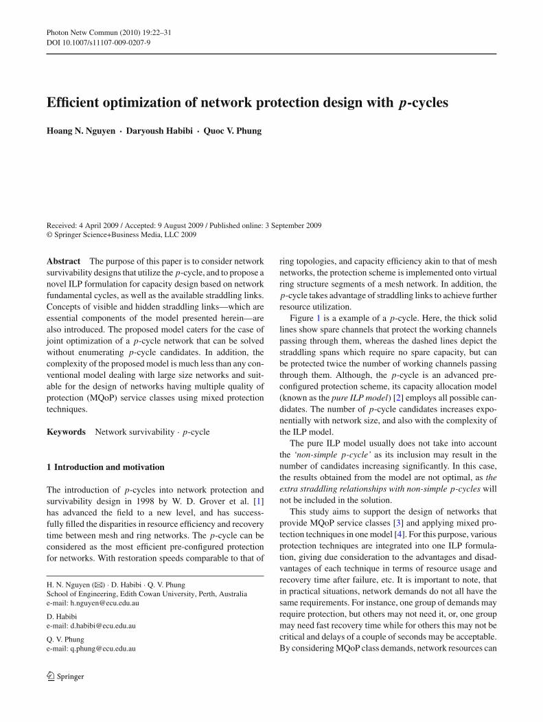
Figure 1 is a example of a p-cycle. Here, the thick solidlines show spare channels that protect the working channelspassing through them, whereas the dashed lines depict thestraddling spans which require no spare capacity, but canbe protected twice the number of working channels passingthrough them. Although, the p-cycle is an advanced pre-configured protection scheme, its capacity allocation model(known as the pure ILP model) [2] employs all possible can-didates. The number of p-cycle candidates increases expo-nentially with network size, and also with the complexity ofthe ILP model.
The pure ILP model usually does not take into accountthe ‘non-simple p-cycle’ as its inclusion may result in thenumber of candidates increasing significantly. In this case,the results obtained from the model are not optimal, as theextra straddling relationships with non-simple p-cycles willnot be included in the solution.
This study aims to support the design of networks thatprovide MQoP service classes [3] and applying mixed pro-tection techniques in one model [4]. For this purpose, variousprotection techniques are integrated into one ILP formula-tion, giving due consideration to the advantages and disad-vantages of each technique in terms of resource usage andrecovery time after failure, etc. It is important to note, thatin practical situations, network demands do not all have thesame requirements. For instance, one group of demands mayrequire protection, but others may not need it, or, one groupmay need fast recovery time while for others this may not becritical and delays of a couple of seconds may be acceptable.By considering MQoP class demands, network resources can
123
Photon Netw Commun (2010) 19:22–31 23
Fig. 1 Typical p-cycle on an arbitrary network
be allocated much more efficiently. However, conventionalprotection scheme designs take many different implementa-tion approaches and nearly all of them contain a very largenumber of variables; for example, the pure ILP model forp-cycles. This makes the process of integrating these intoone model a very difficult task, potentially yielding a highlycomplex model.
In this paper, the complexity problem of the pure ILPmodel is solved by proposing a new ILP formulation usingthe network’s fundamental cycles. Thus, it is proved that theformulation presented in this paper can achieve the optimalsolution. It is also important to note that, in reducing themodel complexity, there is no guarantee of a shorter timeframe resulting in a satisfactory solution when compared withother models. However, it does guarantee to improve on theworst case scenarios within the conventional model. It is notthe purpose of this study to compare the run-times of variousmodels.
2 Background and related works
In this section, a review of some major developments inp-cycle design is presented, and a number of important termsthat are used in the proposed model are defined.
The research on p-cycle design can be categorized intothree main groups:
– Applications - In this category, authors try to implementp-cycles in networks with different design scenarios suchas: multi-failures [5], node protection [6,7], path protec-tion [6,8], and wavelength converter placement [9–11].
– Capacity design and modeling - Research in this cate-gory concentrates on resource allocation, p-cycle place-ment, and model formulation [12–16].
– Evaluation - Here, the focus is on evaluating the reliabil-ity of networks utilizing p-cycles [7,17].
In the first, the application group, researchers attempt todiscover all the potential benefits of the p-cycle for networksurvivability. An investigation into network survivabilitywith p-cycles under multiple failures is performed bySchupke [5], and his report shows that the main factors which
contribute to restorability of a network are the number ofp-cycles allocated and the number of protected workingcapacities. Increasing the number of cycles, and minimiz-ing the maximum working capacity coverage of selectedp-cycles will increase the restorability of the network [14].In general, p-cycles are also known as ‘span-protecting’p-cycles, and can partially protect the network against nodefailures [6,18]. Please note that throughout this paper, theterm p-cycle(s) alone implies ‘span-protecting’ p-cycle(s).A variation of the p-cycle are the ‘encircling’ p-cycles—these have been proposed by Stamatelakis et al [19].Although, encircling p-cycles can protect a network fromnode failures, the p-cycle capacity is high if there are alarger number of transiting traffic streams [7]. The ‘path seg-ment-protecting p-cycle’ or ‘flow-p-cycle’ is another con-cept introduced by Shen et al. [6]. In this context, flow-p-cycles can be more efficient than p-cycles and can protectthe network against both link and node failures. Accordingto [6,7], ‘flow-p-cycles’ have a limitation as they do not havethe “simplicity of failure detection and protection switchingby the node adjacent to the failure”, and thus, switching nodesare required [7]. The study of p-cycle configuration with par-tial wavelength converters by Tianjian Li et al. [11] in bothcases of joint and non-joint optimization1 shows promisingresults, which take into account the full advantages of wave-length converter sharing.
Due to the larger number of variables involved in the pureILP model, it takes a significant amount of computation timein network design to obtain the optimal solution. Therefore,to reduce the computational complexity, several methods ofpre-selecting a reduced number of candidate p-cycles areproposed. A cycle generation algorithm is used to find a goodset of candidates based on a combination of high efficiencycycles and short cycles so that working capacities can beefficiently protected by the candidate cycles [15]. Heuristicalgorithms for finding the optimal p-cycles to protect a givenworking capacity distribution are introduced in [13], wheretwo pre-selection criteria known as the topological score (TS)and the apriori efficiency (AE) of p-cycles are used to getthe set of candidates prior to the ILP formulation. The workin [2] involves the identification of primary p-cycles usingthe straddling link algorithm (SLA), followed by a search forbetter cycles using various search algorithms to produce thefinal set of candidates with highest efficiency. The maximumdeviation compared to the pure ILP model can be up to 14%and varies with network topology. The complexity of thismodel is greatly reduced compared to the pure ILP model,for instance 270 vs. 7321 for the USA network.
1 In joint optimization, the working channels are found at the same timeas the spare channels. In non-joint optimization, the working channelsare assigned in advance.
123
24 Photon Netw Commun (2010) 19:22–31
Dominic A. Schupke [14] introduces a different approachto formulate a non-joint optimization without an enumerationof candidates before optimization. However, the proposedmodel is very complex, and the author suggests a four-stepheuristic algorithm which makes the calculation tractable andachieves a near-optimal solution.
Excepting the use of heuristic programs to search forsuitable p-cycles to protect working capacities, all ILPformulations for p-cycle network design require a set ofcandidates. There is a trade off between the computationalcomplexity given by the number of candidates and the per-formance. By using network fundamental cycles and estab-lishing the set of possible straddling links constructed fromthose fundamental cycles, it is possible to formulate thep-cycle network design in a completely different way, whichis less complex than conventional models, but still able toachieve the best solutions. Here the number of input variablesare significantly reduced, since the number of the network’sfundamental cycles is much less than the number of p-cyclecandidates.
2.1 Necessity of the use of all cycle candidatesfor obtaining optimal solutions
Conceptually, a p-cycle in a network G can be considered asa logical cycle c embedded on G. The p-cycle provides onepre-configured protection path against any failure of on-cyclelinks and two protection paths against failures of straddlinglinks. Figure 2a shows an example in which p-cycle c con-tains five on-cycle links and one straddling link l. In the ‘pure’ILP model, all cycles in a network have to be included in theset of candidates.
In fact, p-cycle c can be constructed by merging twosmaller cycles c1 and c2 and then removing the commonlink l as in Fig. 2b. Generally, any cycle in the network canbe constructed from a number of fundamental cycles whichcontain no straddling links. Figure 2b shows an example inwhich a cycle is constructed by merging three fundamen-tal cycles c1, c2, and c3. Hence, in principle, the set of allfundamental cycles in the network is sufficient for obtainingoptimal solutions in survivable network p-cycle design.
2.2 Preliminary theory
In this section, the preliminary theory relating to theproposed model is discussed. Mathematical and technical
(a) (b) (c)
Fig. 2 Constructing p-cycles
Fig. 3 Typical planar network 9N14S
concepts used in this paper are defined and explained.Furthermore, some terminology is adopted from studied lit-erature.
– A network physical topology is represented as an undi-rected graph G(V, E), where V is a set of network nodesand E is a set of network spans. The term ’span’ impliesthe direct physical connection between two end nodesand ‘link’ refers to the direct logical connection betweentwo end nodes.
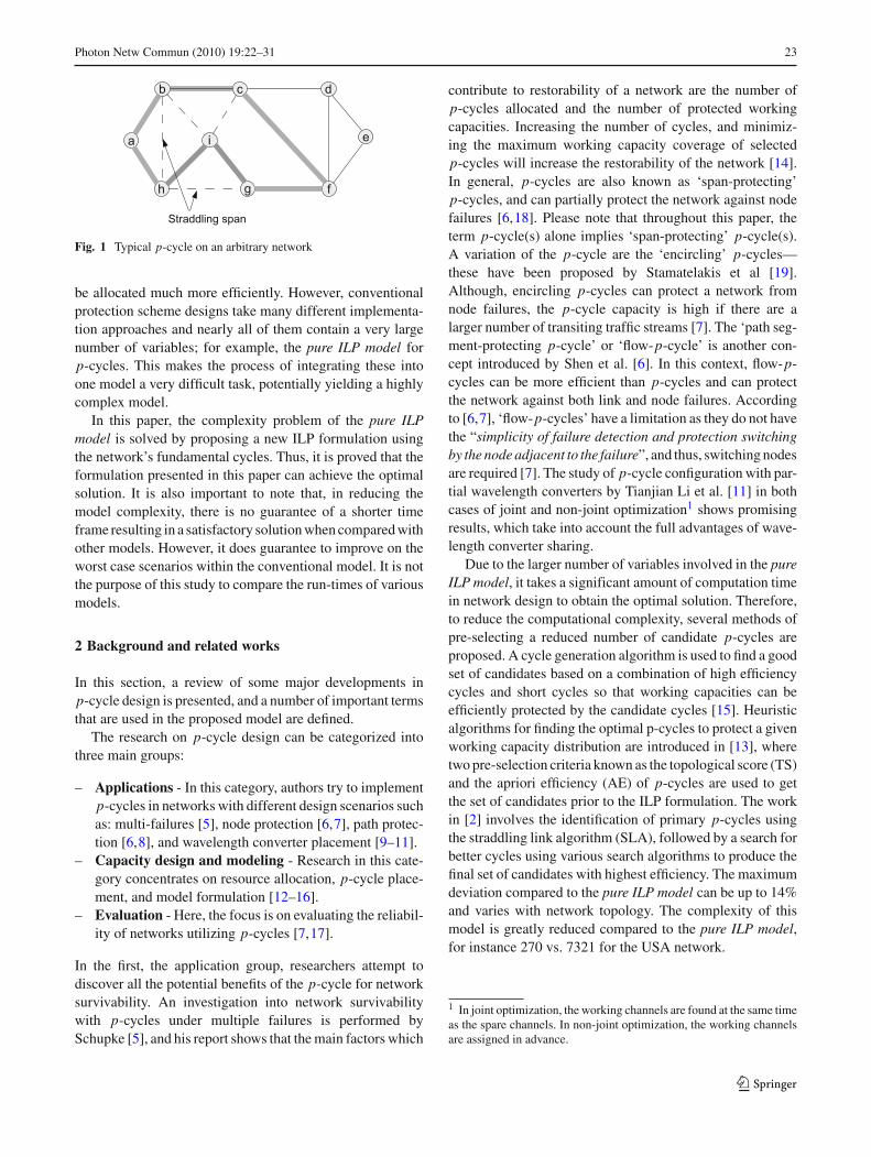
– A cycle in an undirected graph is fundamental if itcontains no straddling link. Figure 3 shows an arbi-trary network with nine nodes and 14 spans, which hasthe following set of fundamental cycles: c1 = {1 2 3},c2 = {3 4 8}, c3 = {5 6 7}, c4 = {5 7 9}, c5 = {2 3 8 6},c6 = {4 5 6 8}, c7 = {2 3 4 5 6} (c7 contains no straddlinglink, thus it is valid).
– A straddling link is called a visible straddling link if it canbe created by merging two different fundamental cycles,and is the only common link that exists between them.Figure 3 shows a typical visible straddling link e3, whichis the common link between two fundamental cycles c1
and c5.– A straddling link is called a hidden straddling link if it can
be created by merging two or more fundamental cyclestogether, but is not part of any of those cycles. Note that,the number of fundamental cycles that are used to gener-ate the hidden straddling links determine the magnitudeof the trade off between resource efficiency, and mini-mum restoration time in case of failure. A longer recov-ery path may result if the hidden straddling link is formedby many fundamental cycles. Figure 3 shows a typicalhidden straddling link e12, which is formed by the twofundamental cycles c4 and c6.
– A non-shareable set: The purposes for finding the non-shareable set � are for preventing the construction of
123
Photon Netw Commun (2010) 19:22–31 25
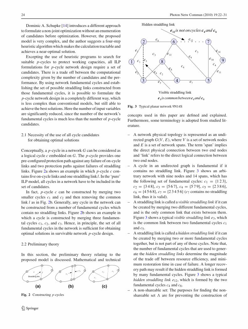
Fig. 4 Illustration of a non-shareable cycle
the encircling p-cycle(s) and guaranteeing that at everysingle node on the selected p-cycles, there must be twonon-straddling spans at each node of the cycle that carrythe spare capacity. Each � contains groups of straddlinglinks. Each group in the set consists of straddling linksthat have at least one common fundamental cycle com-ponent. However, if merging these fundamental cyclesinto a subgraph causes the straddling links to disappear,this group is said to be non-shareable. For example, inFig. 3, straddling link e6 is formed by cycles c2 and c5,straddling link e8 is formed by cycles c2 and c6, and strad-dling link e13 is formed by cycles c5 and c6. When cyclec2 is shared between straddling links, the relevant strad-dling links will vanish, which means that the sharing ofcycles will create a new subgraph {2 3 4 5 6 8} with nostraddling links. Therefore, this group is non-shareable.
2.3 Non-shareable cycles between straddling spans
The non-shareable set contains a number of subsets λi , {i =1, 2..., n} corresponding to the straddling span indices. Ineach subset λi , there may be more than one non-shareablegroup of straddling spans. For example, λ4 of the straddlingspan index 4 has the following non-shareable groups: {4, 6}and {4, 5}. The group {4, 6} contains the straddling spanindices 4 and 6, which use cycles (2–5) and (2–6). Thus itbecomes invalid if they join together as shown in Fig. 4. For agiven graph with K straddling spans (K is an arbitrary num-ber), there will be K subsets containing the non-shareablegroups. The subset does not necessarily contain any of thenon-shareable groups, it can be an empty set.
2.4 Finding a network’s fundamental cycles
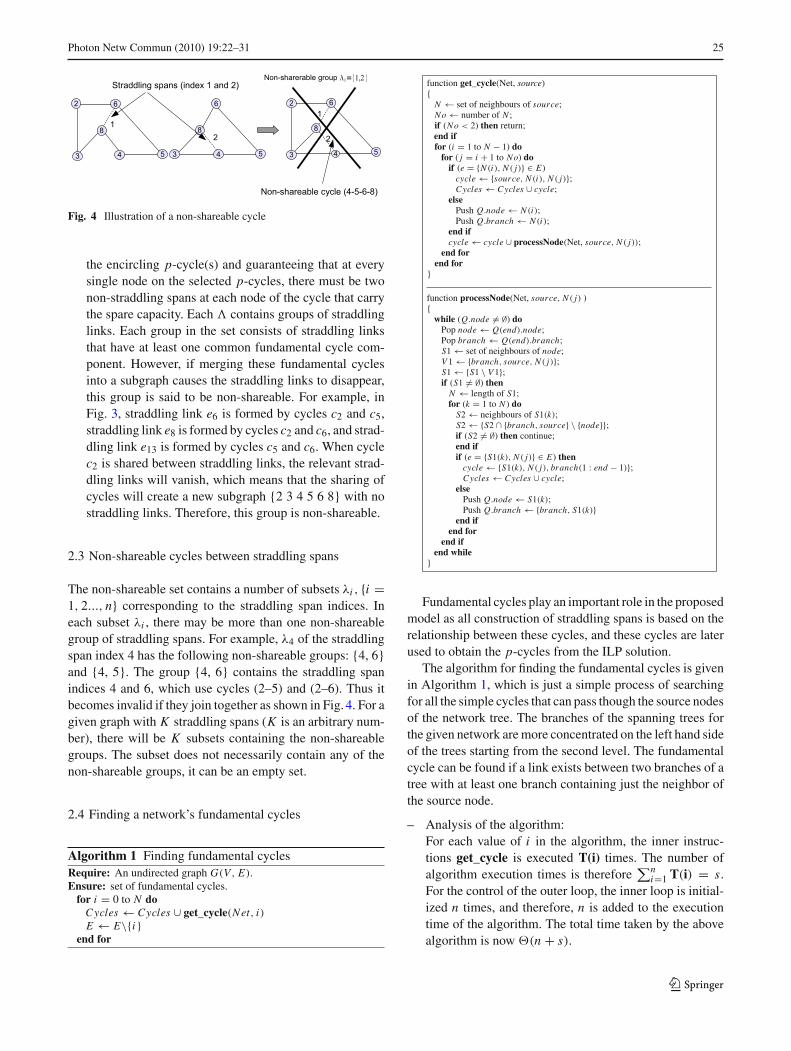
Algorithm 1 Finding fundamental cyclesRequire: An undirected graph G(V, E).Ensure: set of fundamental cycles.
for i = 0 to N doCycles ← Cycles ∪ get_cycle(Net, i)E ← E\{i}
end for
function get_cycle(Net, source){
N ← set of neighbours of source;No← number of N ;if (No < 2) then return;end iffor (i = 1 to N − 1) do
for ( j = i + 1 to No) doif (e = {N (i), N ( j)} ∈ E)
cycle← {source, N (i), N ( j)};Cycles ← Cycles ∪ cycle;
elsePush Q.node← N (i);Push Q.branch ← N (i);
end ifcycle← cycle ∪ processNode(Net, source, N ( j));
end forend for
}
function processNode(Net, source, N ( j) ){
while (Q.node �= ∅) doPop node← Q(end).node;Pop branch ← Q(end).branch;S1← set of neighbours of node;V 1← {branch, source, N ( j)};S1← {S1 \ V 1};if (S1 �= ∅) then
N ← length of S1;for (k = 1 to N ) do
S2← neighbours of S1(k);S2← {S2 ∩ {branch, source} \ {node}};if (S2 �= ∅) then continue;end ifif (e = {S1(k), N ( j)} ∈ E) then
cycle← {S1(k), N ( j), branch(1 : end − 1)};Cycles ← Cycles ∪ cycle;
elsePush Q.node← S1(k);Push Q.branch ← {branch, S1(k)}
end ifend for
end ifend while
}
Fundamental cycles play an important role in the proposedmodel as all construction of straddling spans is based on therelationship between these cycles, and these cycles are laterused to obtain the p-cycles from the ILP solution.
The algorithm for finding the fundamental cycles is givenin Algorithm 1, which is just a simple process of searchingfor all the simple cycles that can pass though the source nodesof the network tree. The branches of the spanning trees forthe given network are more concentrated on the left hand sideof the trees starting from the second level. The fundamentalcycle can be found if a link exists between two branches of atree with at least one branch containing just the neighbor ofthe source node.
– Analysis of the algorithm:For each value of i in the algorithm, the inner instruc-tions get_cycle is executed T(i) times. The number ofalgorithm execution times is therefore
∑ni=1 T(i) = s.
For the control of the outer loop, the inner loop is initial-ized n times, and therefore, n is added to the executiontime of the algorithm. The total time taken by the abovealgorithm is now �(n + s).
123
26 Photon Netw Commun (2010) 19:22–31
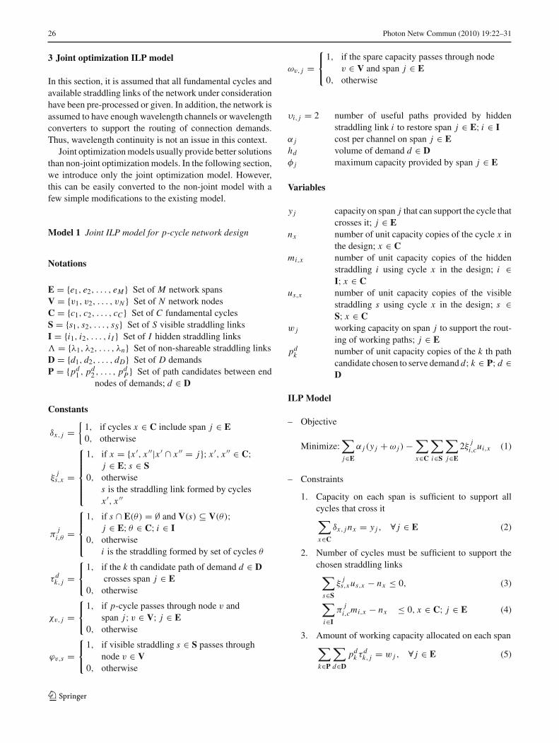
3 Joint optimization ILP model
In this section, it is assumed that all fundamental cycles andavailable straddling links of the network under considerationhave been pre-processed or given. In addition, the network isassumed to have enough wavelength channels or wavelengthconverters to support the routing of connection demands.Thus, wavelength continuity is not an issue in this context.
Joint optimization models usually provide better solutionsthan non-joint optimization models. In the following section,we introduce only the joint optimization model. However,this can be easily converted to the non-joint model with afew simple modifications to the existing model.
Model 1 Joint ILP model for p-cycle network design
Notations
E = {e1, e2, . . . , eM } Set of M network spansV = {v1, v2, . . . , vN } Set of N network nodesC = {c1, c2, . . . , cC } Set of C fundamental cyclesS = {s1, s2, . . . , sS} Set of S visible straddling linksI = {i1, i2, . . . , i I } Set of I hidden straddling links� = {λ1, λ2, . . . , λn} Set of non-shareable straddling linksD = {d1, d2, . . . , dD} Set of D demandsP = {pd
1 , pd2 , . . . , pd
P } Set of path candidates between endnodes of demands; d ∈ D
Constants
δx, j ={
1, if cycles x ∈ C include span j ∈ E0, otherwise
ξj
s,x =
⎧⎪⎪⎪⎪⎨
⎪⎪⎪⎪⎩
1, if x = {x ′, x ′′|x ′ ∩ x ′′ = j}; x ′, x ′′ ∈ C;j ∈ E; s ∈ S
0, otherwises is the straddling link formed by cyclesx ′, x ′′
πj
i,θ =
⎧⎪⎪⎨
⎪⎪⎩
1, if s ∩ E(θ) = ∅ and V(s) ⊆ V(θ);j ∈ E; θ ∈ C; i ∈ I
0, otherwisei is the straddling formed by set of cycles θ
τ dk, j =
⎧⎨
⎩
1, if the k th candidate path of demand d ∈ Dcrosses span j ∈ E
0, otherwise
χv, j =⎧⎨
⎩
1, if p-cycle passes through node v andspan j; v ∈ V; j ∈ E
0, otherwise
ϕv,s =⎧⎨
⎩
1, if visible straddling s ∈ S passes throughnode v ∈ V
0, otherwise
ωv, j =⎧⎨
⎩
1, if the spare capacity passes through nodev ∈ V and span j ∈ E
0, otherwise
υi, j = 2 number of useful paths provided by hiddenstraddling link i to restore span j ∈ E; i ∈ I
α j cost per channel on span j ∈ Ehd volume of demand d ∈ Dφ j maximum capacity provided by span j ∈ E
Variables
y j capacity on span j that can support the cycle thatcrosses it; j ∈ E
nx number of unit capacity copies of the cycle x inthe design; x ∈ C
mi,x number of unit capacity copies of the hiddenstraddling i using cycle x in the design; i ∈I; x ∈ C
us,x number of unit capacity copies of the visiblestraddling s using cycle x in the design; s ∈S; x ∈ C
w j working capacity on span j to support the rout-ing of working paths; j ∈ E
pdk number of unit capacity copies of the k th path
candidate chosen to serve demand d; k ∈ P; d ∈D
ILP Model
– Objective
Minimize:∑
j∈E
α j (y j + ω j )−∑
x∈C
∑
i∈S
∑
j∈E
2ξj
i,cui,x (1)
– Constraints
1. Capacity on each span is sufficient to support allcycles that cross it∑
x∈C
δx, j nx = y j , ∀ j ∈ E (2)
2. Number of cycles must be sufficient to support thechosen straddling links∑
s∈S
ξj
s,x us,x − nx ≤ 0, (3)
∑
i∈I
πj
i,cmi,x − nx ≤ 0, x ∈ C; j ∈ E (4)
3. Amount of working capacity allocated on each span∑
k∈P
∑
d∈D
pdk τ d
k, j = w j , ∀ j ∈ E (5)
123
Photon Netw Commun (2010) 19:22–31 27
4. Spare capacity allocated on links must be sufficientto support 100% restorability∑
i∈I
υi, j mi,x + y j ≥ w j , ∀ j ∈ E; x ∈ C (6)
5. The total number of useful capacity provided by thes th visible straddling link at span j must be less thanor equal to the total number of capacity of that spanformed by the corresponding cycles∑
s∈S
2ξj
s,x us,x − y j ≤ 0, ∀ j ∈ E; x ∈ C (7)
6. A common cycle cannot be shared between straddlinglinks(
∑
s∈S
ξj
s,x us,x +∑
i∈I
πj ′
i,x mi,x
)
− nx ≤ 0
∀{ξ ks,x , π
j ′i,x } ⊆ �
x ∈ C; j, j ′ ∈ E (8)
7. Path selection constraint: Each connection of demandis required to be assigned to one candidate path∑
k∈P
pdk = hd , ∀d ∈ D (9)
8. Total capacity assigned for each span (working plusspare capacity) must be less than or equal to the max-imum capacity that can be provided by the corre-sponding span∑
s∈S
(−2ξj
s,x us,x + yi )+ ω j ≤ φ j
∀ j ∈ E; x ∈ C (10)
9. Number of selected visible straddling spans s throughnode i must be less than or equal to the number ofp-cycles passing through it∑
v∈V
ϕv,sus,x −∑
j∈E
∑
v∈V
χv, j < 0
∀s ∈ S; x ∈ C (11)
10. The total number of links through a node v must beequal to the total number of useful paths provided bythe visible straddling links plus twice the number ofp-cycles through that node. In other words, at everyp-cycle node, there are always two links that are notstraddling links∑
s∈S
2ϕv,sus,x + 2∑
j∈E
χv, j −∑
j∈E
y jωv, j = 0
∀v ∈ V; x ∈ C (12)
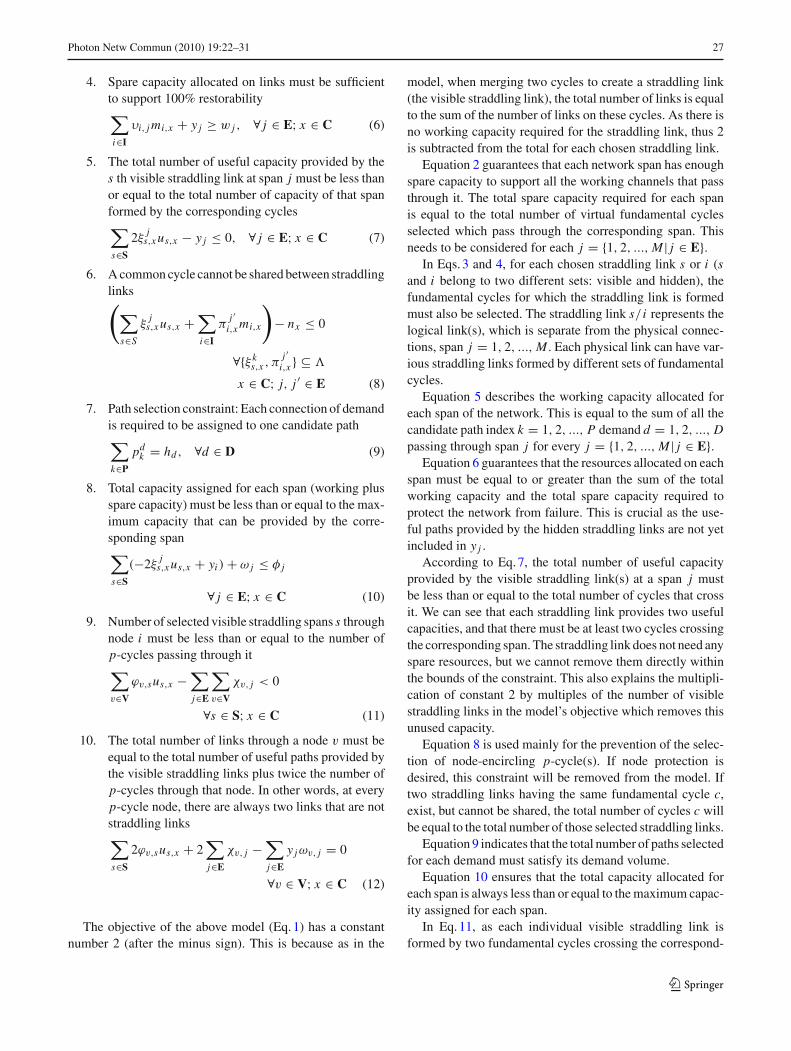
The objective of the above model (Eq. 1) has a constantnumber 2 (after the minus sign). This is because as in the
model, when merging two cycles to create a straddling link(the visible straddling link), the total number of links is equalto the sum of the number of links on these cycles. As there isno working capacity required for the straddling link, thus 2is subtracted from the total for each chosen straddling link.
Equation 2 guarantees that each network span has enoughspare capacity to support all the working channels that passthrough it. The total spare capacity required for each spanis equal to the total number of virtual fundamental cyclesselected which pass through the corresponding span. Thisneeds to be considered for each j = {1, 2, ..., M | j ∈ E}.
In Eqs. 3 and 4, for each chosen straddling link s or i (sand i belong to two different sets: visible and hidden), thefundamental cycles for which the straddling link is formedmust also be selected. The straddling link s/ i represents thelogical link(s), which is separate from the physical connec-tions, span j = 1, 2, ..., M . Each physical link can have var-ious straddling links formed by different sets of fundamentalcycles.
Equation 5 describes the working capacity allocated foreach span of the network. This is equal to the sum of all thecandidate path index k = 1, 2, ..., P demand d = 1, 2, ..., Dpassing through span j for every j = {1, 2, ..., M | j ∈ E}.
Equation 6 guarantees that the resources allocated on eachspan must be equal to or greater than the sum of the totalworking capacity and the total spare capacity required toprotect the network from failure. This is crucial as the use-ful paths provided by the hidden straddling links are not yetincluded in y j .
According to Eq. 7, the total number of useful capacityprovided by the visible straddling link(s) at a span j mustbe less than or equal to the total number of cycles that crossit. We can see that each straddling link provides two usefulcapacities, and that there must be at least two cycles crossingthe corresponding span. The straddling link does not need anyspare resources, but we cannot remove them directly withinthe bounds of the constraint. This also explains the multipli-cation of constant 2 by multiples of the number of visiblestraddling links in the model’s objective which removes thisunused capacity.
Equation 8 is used mainly for the prevention of the selec-tion of node-encircling p-cycle(s). If node protection isdesired, this constraint will be removed from the model. Iftwo straddling links having the same fundamental cycle c,exist, but cannot be shared, the total number of cycles c willbe equal to the total number of those selected straddling links.
Equation 9 indicates that the total number of paths selectedfor each demand must satisfy its demand volume.
Equation 10 ensures that the total capacity allocated foreach span is always less than or equal to the maximum capac-ity assigned for each span.
In Eq. 11, as each individual visible straddling link isformed by two fundamental cycles crossing the correspond-
123
28 Photon Netw Commun (2010) 19:22–31
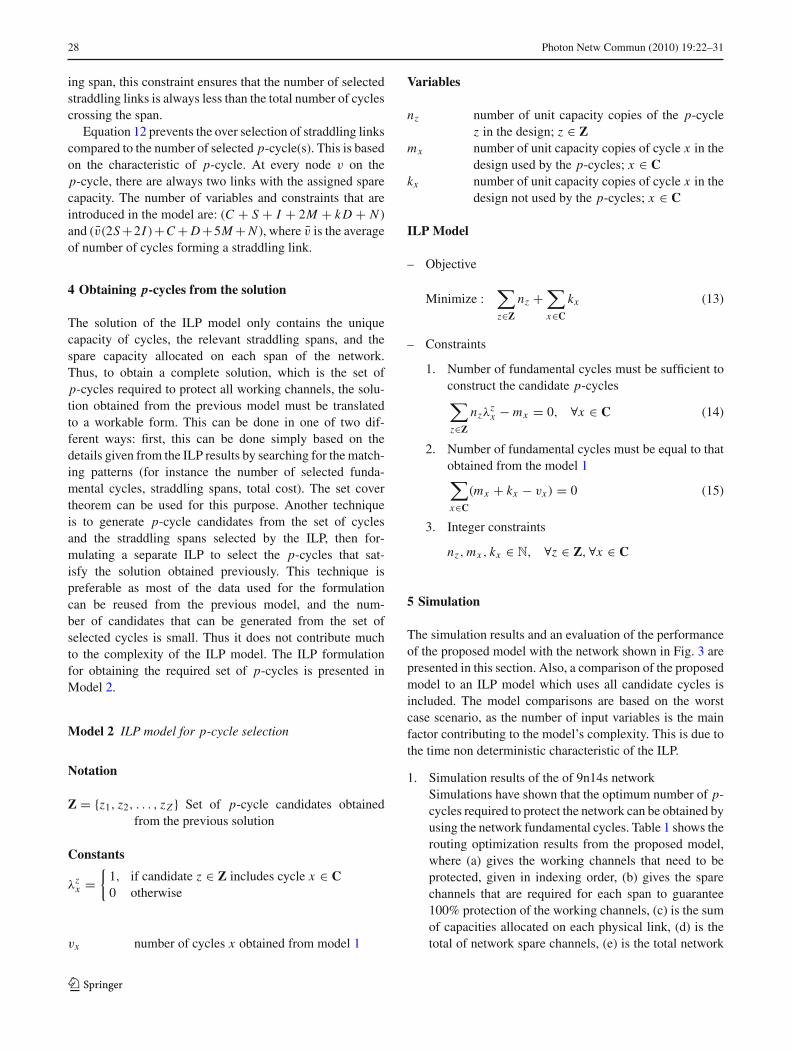
ing span, this constraint ensures that the number of selectedstraddling links is always less than the total number of cyclescrossing the span.
Equation 12 prevents the over selection of straddling linkscompared to the number of selected p-cycle(s). This is basedon the characteristic of p-cycle. At every node v on thep-cycle, there are always two links with the assigned sparecapacity. The number of variables and constraints that areintroduced in the model are: (C + S + I + 2M + k D + N )and (v̄(2S+2I )+C+D+5M+N ), where v̄ is the averageof number of cycles forming a straddling link.
4 Obtaining p-cycles from the solution
The solution of the ILP model only contains the uniquecapacity of cycles, the relevant straddling spans, and thespare capacity allocated on each span of the network.Thus, to obtain a complete solution, which is the set ofp-cycles required to protect all working channels, the solu-tion obtained from the previous model must be translatedto a workable form. This can be done in one of two dif-ferent ways: first, this can be done simply based on thedetails given from the ILP results by searching for the match-ing patterns (for instance the number of selected funda-mental cycles, straddling spans, total cost). The set covertheorem can be used for this purpose. Another techniqueis to generate p-cycle candidates from the set of cyclesand the straddling spans selected by the ILP, then for-mulating a separate ILP to select the p-cycles that sat-isfy the solution obtained previously. This technique ispreferable as most of the data used for the formulationcan be reused from the previous model, and the num-ber of candidates that can be generated from the set ofselected cycles is small. Thus it does not contribute muchto the complexity of the ILP model. The ILP formulationfor obtaining the required set of p-cycles is presented inModel 2.
Model 2 ILP model for p-cycle selection
Notation
Z = {z1, z2, . . . , zZ } Set of p-cycle candidates obtainedfrom the previous solution
Constants
λzx =
{1, if candidate z ∈ Z includes cycle x ∈ C0 otherwise
vx number of cycles x obtained from model 1
Variables
nz number of unit capacity copies of the p-cyclez in the design; z ∈ Z
mx number of unit capacity copies of cycle x in thedesign used by the p-cycles; x ∈ C
kx number of unit capacity copies of cycle x in thedesign not used by the p-cycles; x ∈ C
ILP Model
– Objective
Minimize :∑
z∈Z
nz +∑
x∈C
kx (13)
– Constraints
1. Number of fundamental cycles must be sufficient toconstruct the candidate p-cycles∑
z∈Z
nzλzx − mx = 0, ∀x ∈ C (14)
2. Number of fundamental cycles must be equal to thatobtained from the model 1∑
x∈C
(mx + kx − vx ) = 0 (15)
3. Integer constraints
nz, mx , kx ∈ N, ∀z ∈ Z,∀x ∈ C
5 Simulation
The simulation results and an evaluation of the performanceof the proposed model with the network shown in Fig. 3 arepresented in this section. Also, a comparison of the proposedmodel to an ILP model which uses all candidate cycles isincluded. The model comparisons are based on the worstcase scenario, as the number of input variables is the mainfactor contributing to the model’s complexity. This is due tothe time non deterministic characteristic of the ILP.
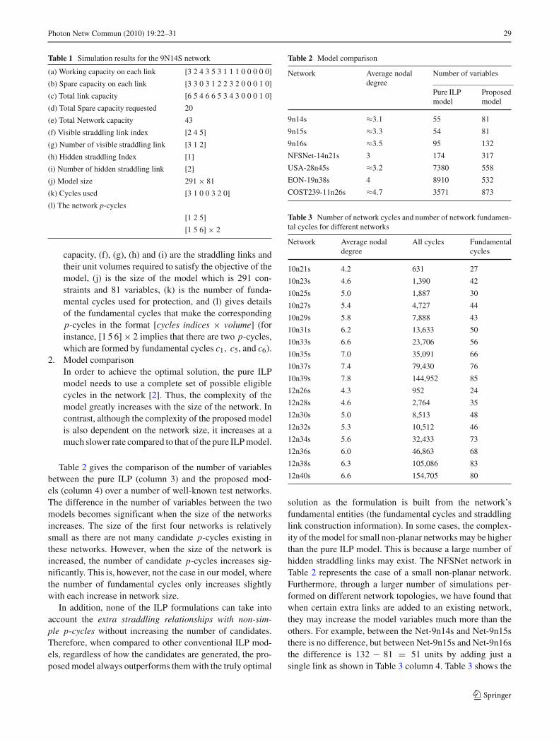
1. Simulation results of the of 9n14s networkSimulations have shown that the optimum number of p-cycles required to protect the network can be obtained byusing the network fundamental cycles. Table 1 shows therouting optimization results from the proposed model,where (a) gives the working channels that need to beprotected, given in indexing order, (b) gives the sparechannels that are required for each span to guarantee100% protection of the working channels, (c) is the sumof capacities allocated on each physical link, (d) is thetotal of network spare channels, (e) is the total network
123
Photon Netw Commun (2010) 19:22–31 29
Table 1 Simulation results for the 9N14S network
(a) Working capacity on each link [3 2 4 3 5 3 1 1 1 0 0 0 0 0]
(b) Spare capacity on each link [3 3 0 3 1 2 2 3 2 0 0 0 1 0]
(c) Total link capacity [6 5 4 6 6 5 3 4 3 0 0 0 1 0]
(d) Total Spare capacity requested 20
(e) Total Network capacity 43
(f) Visible straddling link index [2 4 5]
(g) Number of visible straddling link [3 1 2]
(h) Hidden straddling Index [1]
(i) Number of hidden straddling link [2]
(j) Model size 291× 81
(k) Cycles used [3 1 0 0 3 2 0]
(l) The network p-cycles
[1 2 5]
[1 5 6] × 2
capacity, (f), (g), (h) and (i) are the straddling links andtheir unit volumes required to satisfy the objective of themodel, (j) is the size of the model which is 291 con-straints and 81 variables, (k) is the number of funda-mental cycles used for protection, and (l) gives detailsof the fundamental cycles that make the correspondingp-cycles in the format [cycles indices × volume] (forinstance, [1 5 6] × 2 implies that there are two p-cycles,which are formed by fundamental cycles c1, c5, and c6).
2. Model comparisonIn order to achieve the optimal solution, the pure ILPmodel needs to use a complete set of possible eligiblecycles in the network [2]. Thus, the complexity of themodel greatly increases with the size of the network. Incontrast, although the complexity of the proposed modelis also dependent on the network size, it increases at amuch slower rate compared to that of the pure ILP model.
Table 2 gives the comparison of the number of variablesbetween the pure ILP (column 3) and the proposed mod-els (column 4) over a number of well-known test networks.The difference in the number of variables between the twomodels becomes significant when the size of the networksincreases. The size of the first four networks is relativelysmall as there are not many candidate p-cycles existing inthese networks. However, when the size of the network isincreased, the number of candidate p-cycles increases sig-nificantly. This is, however, not the case in our model, wherethe number of fundamental cycles only increases slightlywith each increase in network size.
In addition, none of the ILP formulations can take intoaccount the extra straddling relationships with non-sim-ple p-cycles without increasing the number of candidates.Therefore, when compared to other conventional ILP mod-els, regardless of how the candidates are generated, the pro-posed model always outperforms them with the truly optimal
Table 2 Model comparison
Network Average nodal Number of variablesdegree
Pure ILPmodel
Proposedmodel
9n14s ≈3.1 55 81
9n15s ≈3.3 54 81
9n16s ≈3.5 95 132
NFSNet-14n21s 3 174 317
USA-28n45s ≈3.2 7380 558
EON-19n38s 4 8910 532
COST239-11n26s ≈4.7 3571 873
Table 3 Number of network cycles and number of network fundamen-tal cycles for different networks
Network Average nodaldegree
All cycles Fundamentalcycles
10n21s 4.2 631 27
10n23s 4.6 1,390 42
10n25s 5.0 1,887 30
10n27s 5.4 4,727 44
10n29s 5.8 7,888 43
10n31s 6.2 13,633 50
10n33s 6.6 23,706 56
10n35s 7.0 35,091 66
10n37s 7.4 79,430 76
10n39s 7.8 144,952 85
12n26s 4.3 952 24
12n28s 4.6 2,764 35
12n30s 5.0 8,513 48
12n32s 5.3 10,512 46
12n34s 5.6 32,433 73
12n36s 6.0 46,863 68
12n38s 6.3 105,086 83
12n40s 6.6 154,705 80
solution as the formulation is built from the network’sfundamental entities (the fundamental cycles and straddlinglink construction information). In some cases, the complex-ity of the model for small non-planar networks may be higherthan the pure ILP model. This is because a large number ofhidden straddling links may exist. The NFSNet network inTable 2 represents the case of a small non-planar network.Furthermore, through a larger number of simulations per-formed on different network topologies, we have found thatwhen certain extra links are added to an existing network,they may increase the model variables much more than theothers. For example, between the Net-9n14s and Net-9n15sthere is no difference, but between Net-9n15s and Net-9n16sthe difference is 132 − 81 = 51 units by adding just asingle link as shown in Table 3 column 4. Table 3 shows the
123
30 Photon Netw Commun (2010) 19:22–31
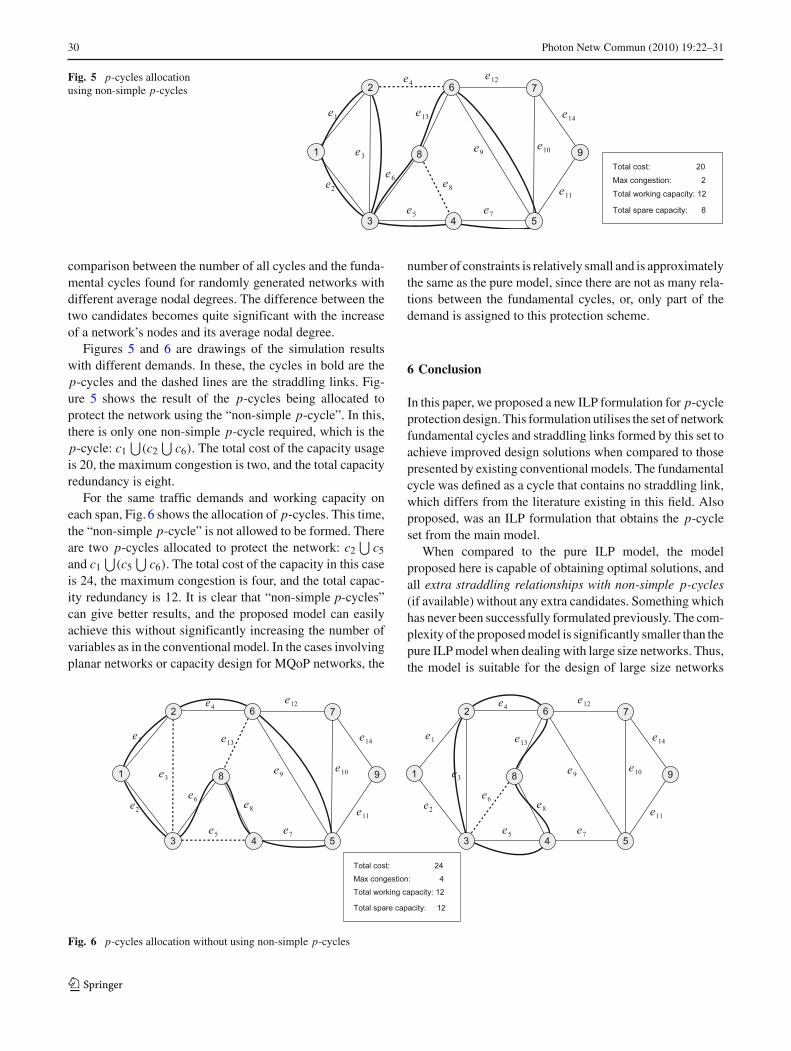
Fig. 5 p-cycles allocationusing non-simple p-cycles
comparison between the number of all cycles and the funda-mental cycles found for randomly generated networks withdifferent average nodal degrees. The difference between thetwo candidates becomes quite significant with the increaseof a network’s nodes and its average nodal degree.
Figures 5 and 6 are drawings of the simulation resultswith different demands. In these, the cycles in bold are thep-cycles and the dashed lines are the straddling links. Fig-ure 5 shows the result of the p-cycles being allocated toprotect the network using the “non-simple p-cycle”. In this,there is only one non-simple p-cycle required, which is thep-cycle: c1
⋃(c2
⋃c6). The total cost of the capacity usage
is 20, the maximum congestion is two, and the total capacityredundancy is eight.
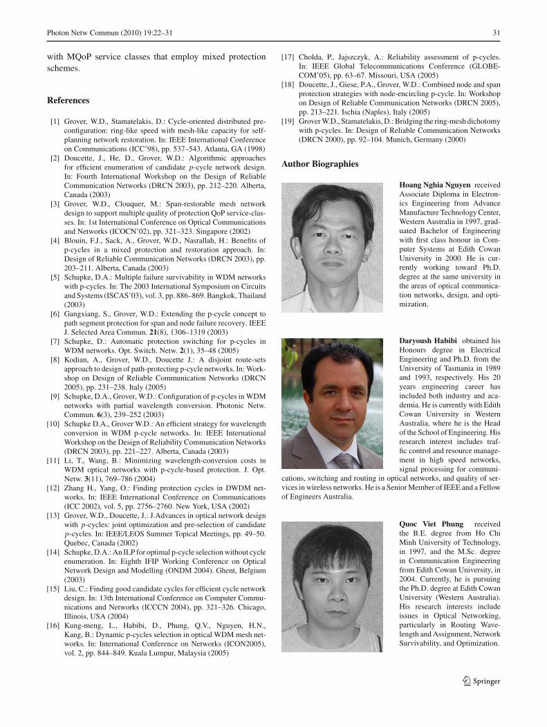
For the same traffic demands and working capacity oneach span, Fig. 6 shows the allocation of p-cycles. This time,the “non-simple p-cycle” is not allowed to be formed. Thereare two p-cycles allocated to protect the network: c2
⋃c5
and c1⋃
(c5⋃
c6). The total cost of the capacity in this caseis 24, the maximum congestion is four, and the total capac-ity redundancy is 12. It is clear that “non-simple p-cycles”can give better results, and the proposed model can easilyachieve this without significantly increasing the number ofvariables as in the conventional model. In the cases involvingplanar networks or capacity design for MQoP networks, the
number of constraints is relatively small and is approximatelythe same as the pure model, since there are not as many rela-tions between the fundamental cycles, or, only part of thedemand is assigned to this protection scheme.
6 Conclusion
In this paper, we proposed a new ILP formulation for p-cycleprotection design. This formulation utilises the set of networkfundamental cycles and straddling links formed by this set toachieve improved design solutions when compared to thosepresented by existing conventional models. The fundamentalcycle was defined as a cycle that contains no straddling link,which differs from the literature existing in this field. Alsoproposed, was an ILP formulation that obtains the p-cycleset from the main model.
When compared to the pure ILP model, the modelproposed here is capable of obtaining optimal solutions, andall extra straddling relationships with non-simple p-cycles(if available) without any extra candidates. Something whichhas never been successfully formulated previously. The com-plexity of the proposed model is significantly smaller than thepure ILP model when dealing with large size networks. Thus,the model is suitable for the design of large size networks
Fig. 6 p-cycles allocation without using non-simple p-cycles
123
Photon Netw Commun (2010) 19:22–31 31
with MQoP service classes that employ mixed protectionschemes.
References
[1] Grover, W.D., Stamatelakis, D.: Cycle-oriented distributed pre-configuration: ring-like speed with mesh-like capacity for self-planning network restoration. In: IEEE International Conferenceon Communications (ICC’98), pp. 537–543. Atlanta, GA (1998)
[2] Doucette, J., He, D., Grover, W.D.: Algorithmic approachesfor efficient enumeration of candidate p-cycle network design.In: Fourth International Workshop on the Design of ReliableCommunication Networks (DRCN 2003), pp. 212–220. Alberta,Canada (2003)
[3] Grover, W.D., Clouquer, M.: Span-restorable mesh networkdesign to support multiple quality of protection QoP service-clas-ses. In: 1st International Conference on Optical Communicationsand Networks (ICOCN’02), pp. 321–323. Singapore (2002)
[4] Blouin, F.J., Sack, A., Grover, W.D., Nasrallah, H.: Benefits ofp-cycles in a mixed protection and restoration approach. In:Design of Reliable Communication Networks (DRCN 2003), pp.203–211. Alberta, Canada (2003)
[5] Schupke, D.A.: Multiple failure survivability in WDM networkswith p-cycles. In: The 2003 International Symposium on Circuitsand Systems (ISCAS’03), vol. 3, pp. 886–869. Bangkok, Thailand(2003)
[6] Gangxiang, S., Grover, W.D.: Extending the p-cycle concept topath segment protection for span and node failure recovery. IEEEJ. Selected Area Commun. 21(8), 1306–1319 (2003)
[7] Schupke, D.: Automatic protection switching for p-cycles inWDM networks. Opt. Switch. Netw. 2(1), 35–48 (2005)
[8] Kodian, A., Grover, W.D., Doucette J.: A disjoint route-setsapproach to design of path-protecting p-cycle networks. In: Work-shop on Design of Reliable Communication Networks (DRCN2005), pp. 231–238. Italy (2005)
[9] Schupke, D.A., Grover, W.D.: Configuration of p-cycles in WDMnetworks with partial wavelength conversion. Photonic Netw.Commun. 6(3), 239–252 (2003)
[10] Schupke D.A., Grover W.D.: An efficient strategy for wavelengthconversion in WDM p-cycle networks. In: IEEE InternationalWorkshop on the Design of Reliability Communication Networks(DRCN 2003), pp. 221–227. Alberta, Canada (2003)
[11] Li, T., Wang, B.: Minimizing wavelength-conversion costs inWDM optical networks with p-cycle-based protection. J. Opt.Netw. 3(11), 769–786 (2004)
[12] Zhang H., Yang, O.: Finding protection cycles in DWDM net-works. In: IEEE International Conference on Communications(ICC 2002), vol. 5, pp. 2756–2760. New York, USA (2002)
[13] Grover, W.D., Doucette, J.: J.Advances in optical network designwith p-cycles: joint optimization and pre-selection of candidatep-cycles. In: IEEE/LEOS Summer Topical Meetings, pp. 49–50.Quebec, Canada (2002)
[14] Schupke, D.A.: An ILP for optimal p-cycle selection without cycleenumeration. In: Eighth IFIP Working Conference on OpticalNetwork Design and Modelling (ONDM 2004). Ghent, Belgium(2003)
[15] Liu, C.: Finding good candidate cycles for efficient cycle networkdesign. In: 13th International Conference on Computer Commu-nications and Networks (ICCCN 2004), pp. 321–326. Chicago,Illinois, USA (2004)
[16] Kung-meng, L., Habibi, D., Phung, Q.V., Nguyen, H.N.,Kang, B.: Dynamic p-cycles selection in optical WDM mesh net-works. In: International Conference on Networks (ICON2005),vol. 2, pp. 844–849. Kuala Lumpur, Malaysia (2005)
[17] Cholda, P., Jajszczyk, A.: Reliability assessment of p-cycles.In: IEEE Global Telecommunications Conference (GLOBE-COM’05), pp. 63–67. Missouri, USA (2005)
[18] Doucette, J., Giese, P.A., Grover, W.D.: Combined node and spanprotection strategies with node-encircling p-cycle. In: Workshopon Design of Reliable Communication Networks (DRCN 2005),pp. 213–221. Ischia (Naples), Italy (2005)
[19] Grover W.D., Stamatelakis, D.: Bridging the ring-mesh dichotomywith p-cycles. In: Design of Reliable Communication Networks(DRCN 2000), pp. 92–104. Munich, Germany (2000)
Author Biographies
Hoang Nghia Nguyen receivedAssociate Diploma in Electron-ics Engineering from AdvanceManufacture Technology Center,Western Australia in 1997, grad-uated Bachelor of Engineeringwith first class honour in Com-puter Systems at Edith CowanUniversity in 2000. He is cur-rently working toward Ph.D.degree at the same university inthe areas of optical communica-tion networks, design, and opti-mization.
Daryoush Habibi obtained hisHonours degree in ElectricalEngineering and Ph.D. from theUniversity of Tasmania in 1989and 1993, respectively. His 20years engineering career hasincluded both industry and aca-demia. He is currently with EdithCowan University in WesternAustralia, where he is the Headof the School of Engineering. Hisresearch interest includes traf-fic control and resource manage-ment in high speed networks,signal processing for communi-
cations, switching and routing in optical networks, and quality of ser-vices in wireless networks. He is a Senior Member of IEEE and a Fellowof Engineers Australia.
Quoc Viet Phung receivedthe B.E. degree from Ho ChiMinh University of Technology,in 1997, and the M.Sc. degreein Communication Engineeringfrom Edith Cowan University, in2004. Currently, he is pursuingthe Ph.D. degree at Edith CowanUniversity (Western Australia).His research interests includeissues in Optical Networking,particularly in Routing Wave-length and Assignment, NetworkSurvivability, and Optimization.
123
Related Documents