Confidential © ams AG 2014 Efficient Motor Commutation through Advanced Position Sensing: The Trend towards Brushless DC Motors Heinz Oyrer, Senior Manager Global Marketing Sensors Expo and Conference , June 24-26, 2014

Efficient Motor Commutation through Advanced Position Sensing - The Trend towards Brushless DC Motors
Jul 13, 2015
Welcome message from author
This document is posted to help you gain knowledge. Please leave a comment to let me know what you think about it! Share it to your friends and learn new things together.
Transcript

Confidential © ams AG 2014
Efficient Motor Commutation through
Advanced Position Sensing:
The Trend towards Brushless DC
Motors
Heinz Oyrer, Senior Manager Global Marketing
Sensors Expo and Conference , June 24-26, 2014

Confidential © ams AG 2014
Page 2
EFFICIENT MOTOR COMMUTATION THROUGH
ADVANCED POSITION SENSING The Trend towards Brushless DC Motors
EFFICIENCY OF ELECTRICAL MOTORS
BRUSHLESS DC MOTORS
MOTOR POSITION SENSOR
INTEGRATED POSITION SENSING IN EPS

Confidential © ams AG 2014
Page 3
• Electric motors are the single biggest
consumer of electricity.
• They account for about 2/3 of industrial
power consumption and, about 45% of global
power consumption, according to a new
analysis by the International Energy Agency
Source: CleanTechnica, abb.com/energyefficiency
Electric Motors Use Majority of Global Electricity

Confidential © ams AG 2014
Page 4
• Thousands of words and column inches are
devoted to topics such as nuclear power,
renewable energy, and electric vehicles
• Rarely discussed is the fact that the majority
of electric motors are inefficient,
oversized, or running when they don’t
need to be running.
Source: CleanTechnica, abb.com/energyefficiency
Majority of Electric Motors are Inefficient

Confidential © ams AG 2014
Page 5
Opportunities for Efficiency
• Addressing the efficiency of electric motors is
an important topic that needs to be tackled.
Source: CleanTechnica, abb.com/energyefficiency

Confidential © ams AG 2014
Page 6
An electric motor system comprises three layers of
equipment :
1. Electric motor: a fully functioning electric
motor runs from the electric grid.
2. Core motor system. The core motor
system controls torque and speed. It
consists of the electric motor, its driven
piece of mechanical equipment along with
the necessary interconnection and a
variable‐speed drive (VSD) system between
the grid and the motor.
3. The total motor system consists of the
core motor system plus the eventual
application of power and the electric
equipment between the grid and the motor.
Energy‐efficiency for Electric Motor‐driven Systems
Source: International Energy Agency,
Energy-Efficiency Policy Opportunities
for Electric Motor-Driven Systems 2011

Confidential © ams AG 2014
Page 7
EFFICIENT MOTOR COMMUTATION THROUGH
ADVANCED POSITION SENSING The Trend towards Brushless DC Motors
EFFICIENCY OF ELECTRICAL MOTORS
BRUSHLESS DC MOTORS
MOTOR POSITION SENSOR
INTEGRATED POSITION SENSING IN EPS

Confidential © ams AG 2014
Page 8
Motor Types Key Parameters
Stepper Motor AC Induction Brushless / Servo Universal
Confidential © ams AG 2014
Page 9
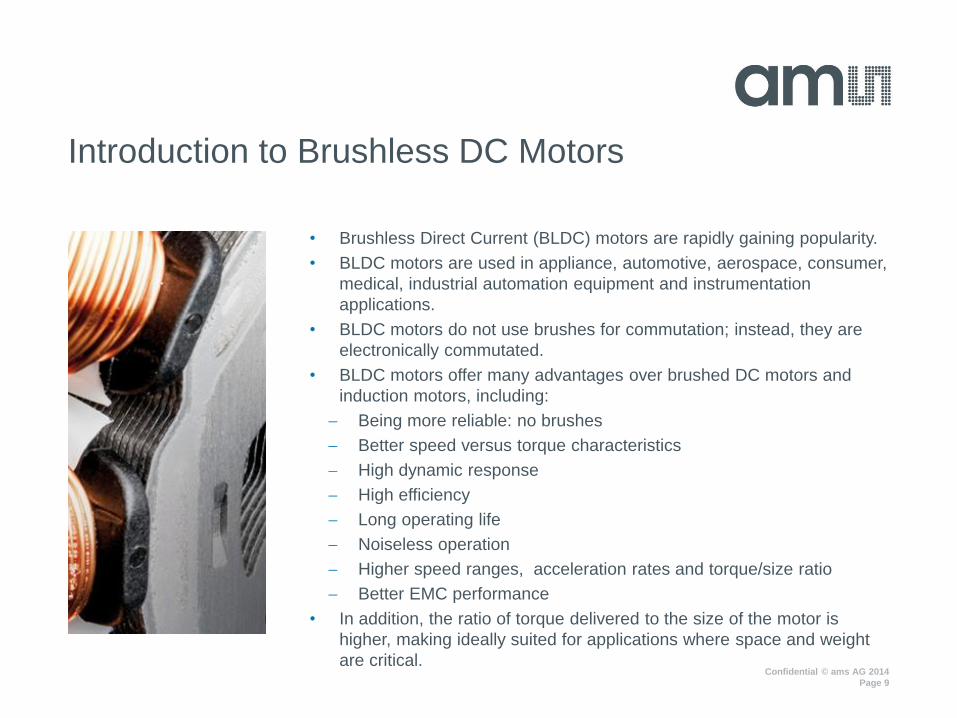
• Brushless Direct Current (BLDC) motors are rapidly gaining popularity.
• BLDC motors are used in appliance, automotive, aerospace, consumer,
medical, industrial automation equipment and instrumentation
applications.
• BLDC motors do not use brushes for commutation; instead, they are
electronically commutated.
• BLDC motors offer many advantages over brushed DC motors and
induction motors, including:
Being more reliable: no brushes
Better speed versus torque characteristics
High dynamic response
High efficiency
Long operating life
Noiseless operation
Higher speed ranges, acceleration rates and torque/size ratio
Better EMC performance
• In addition, the ratio of torque delivered to the size of the motor is
higher, making ideally suited for applications where space and weight
are critical.
Introduction to Brushless DC Motors

Confidential © ams AG 2014
Page 10
Brushless Direct Current (BLDC) motors are rapidly gaining popularity
• "Sales volumes of brushless DC motors are forecast to grow much
faster than that of either brushed DC motors or stepper motors. Major
advantages of brushless DC motors include higher efficiency at
converting electricity into mechanical power, reduced noise, longer
lifetime and higher reliability.“, Michael Liu, IMS Research
• E-Motor market is growing 40% from 2012 to 2017
Government regulations worldwide
• Require the industry to implement new efficiency classes IE1, IE2,
IE3, … (IE = International Efficiency to reduce CO2 (higher efficiency
means better motor control)
Key requirements in Automotive market
• Reducing CO2-emissions by saving weight and reducing fuel
consumption
• Improve passenger safety and anti-collision systems and electric
stability program
• Improve passenger comfort to reduce noise and improve handling
The Trend Towards Brushless Motors

Confidential © ams AG 2014
Page 11
• Today: Cost of brushed > Cost of BLDC but < Cost of BLDC +
electronics
• Near future: Cost of brushed = Cost of BLDC + PCB
• Future: Cost of brushed > Cost of BLDC + electronics all
brushed motors will be replaced by BLDC
• Most brushed motors do not have electronics but all BLDC need it.
(Cost of brushed – Cost of BLDC) = available amount for
electronics, however also cost pressure for electronics
• Reduce the number of gearboxes by increasing the torque of the
motor - no gearbox means lower motor speed – direct drive
Cost Pressure for Brushless Motors

Confidential © ams AG 2014
Page 12
• BLDC motors consist of a rotating permanent
magnet (rotor) and (min) 3 equally spaced
fixed windings (stator).
• By controlling the currents in the stator, a
magnetic field of arbitrary direction and
magnitude can be produced.
• Torque is produced by the attraction and
repulsion between the rotor and stator field
• In the case of a brushed DC motor, feedback
is implemented using a mechanical
commutator and brushes. In a BLDC motor, it
is achieved using multiple feedback sensors.
• The most commonly used sensors are hall
sensors and optical encoders.
Brushless Motor Basics

Confidential © ams AG 2014
Page 13
In order to apply the most efficient stator field, the position of the rotor must be known. There are several methods to detect the rotor position:
• Sensor-less
By measuring back-EMF and/or stator coil currents
• Optical switches
Using a coded disc
• Resolvers
Flanged onto the rotor shaft
• Hall switches
Embedded into the stator, actuated by the rotor magnet. Based on the combination of these three Hall sensor signals, the exact sequence of commutation can be determined.
• Integrated Hall sensors = Position Sensor
A Hall effect magnetic position sensor is a transducer that varies its output voltage in response to a magnetic field.
Mounted at the end of the shaft
Rotor Position Feedback

Confidential © ams AG 2014
Page 14
Motor Application Requirements
Requirement Sensor - Types Sensorless
Speed control • Magnetic Position Sensor
• Optical Encoder
Sensorless is possible with back
EMF and FOC at speed > 300rpm*
Commutation
• 3 discrete Hall switches
• Magnetic Position Sensor
• Optical Encoder
Sensorless is possible with back
EMF and FOC at speed > 300rpm*
Position Control
Torque Control
• Optical Encoder
• Magnetic Position Sensor
• Inductive (Resolver)
Sensorless not possible
Sensor always needed
EMF … electro magnetic force
FOC … field oriented control
* Lower rpm possible but very complex algorithms

Confidential © ams AG 2014
Page 15
EFFICIENT MOTOR COMMUTATION THROUGH
ADVANCED POSITION SENSING The Trend towards Brushless DC Motors
EFFICIENCY OF ELECTRICAL MOTORS
BRUSHLESS DC MOTORS
MOTOR POSITION SENSOR
INTEGRATED POSITION SENSING IN EPS

Confidential © ams AG 2014
Page 16
• One single Hall sensor can reduce component cost, the cost for
precision mounting is saved
• It can output the rotor position by one single sensor and deliver the
absolute angle position of the rotor during start
• Electric brake and hold
• Increase efficiency by software
• Applicable for small motor designs
• The sensor does not need to reside on specific positions inside the
motor which results in more design freedom for the motor designer
• Power efficient (no power dissipation like with sensor-less/shunt)
• Easy integration
• High temperature environment
• High start-up torque, low torque ripple, low audible noise
• High accuracy, excellent reliability and high safety levels
(automotive)
When Do Customers Need a Position Sensor?

Confidential © ams AG 2014
Page 17
Efficient motor commutation
• Needs fast and accurate position measurement
Key enablers
• Measurement quantization (resolution)
• INL (integral-non-linearity)
• Noise
• System propagation delay
Benchmark
• INL (8mm Magnet + displacement) = 1.2deg
• Noise = 0.05deg
• System propagation delay = 1.9µs
• Core resolution = 14bit
• Maximum Speed = 28.000 rpm
• Flexible choice of interfaces
• Immunity to external stray field
Position Sensing for Efficient Motor Commutation

Confidential © ams AG 2014
Page 18
Angle accuracy: ideal slope

Confidential © ams AG 2014
Page 19
Angle accuracy: system propagation delay

Confidential © ams AG 2014
Page 20
Integrated Dynamic Angle*) Error Compensation
Dynamic Angle Error
Hardware Compensation integrated!
No Software needed!
External HW + SW compensation needed
Ma
gne
tic P
ositio
n S
en
sor
Syste
m
*) DAEC™ - patent pending

Confidential © ams AG 2014
Page 21
EFFICIENT MOTOR COMMUTATION THROUGH
ADVANCED POSITION SENSING The Trend towards Brushless DC Motors
EFFICIENCY OF ELECTRICAL MOTORS
BRUSHLESS DC MOTORS
MOTOR POSITION SENSOR
INTEGRATED POSITION SENSING IN EPS

Confidential © ams AG 2014
Page 22
• Magnetic position sensing is now becoming the
leading solution for automobile EPS systems that
have greater operational effectiveness.
• Sophisticated sensor devices with multiple
sensing elements on a single die enable faster
and more accurate acquisition of information
required by the EPS system.
• Precise position of the automobile's steering
wheel, improved performance of its EPS system
while keeping costs and required space to a
minimum.
Stability over temperature
Robustness against tolerances
Robustness against interfering field
Up to 7 pole pairs
Up to 28.000 rpm (depending on application)
Angle error <1° deg
ISO26262-compliance (depending on OEM
specification)
Integrated Position Sensing in EPS
BLDC
Rotor Position Sensor
Electric Power Steering dominates the steering market,
EPS outperforms other markets in growth.
The motor position
sensor controls the
commutation of a
brushless DC motor
employed in the
system.
Confidential © ams AG 2014
Page 23
Summary
• Improving the efficiency of electric motors has become an important topic at a global level
• The core motor system offers a great potential for savings
Controlling torque and speed as well costs
BLDC motors as a key enabler
• BLDC motors offer many advantages over brushed DC motors and induction motors.
Better speed versus torque characteristics, high dynamic response, high efficiency, long
operating life, noiseless operation, higher speed ranges, rugged construction and so on.
Torque delivered to the motor size is higher, making it ideal for applications where space and
weight are critical factors.
BLDC motors find wide spread adoption in applications such as automotive, appliance,
aerospace, consumer, medical, instrumentation and automation
• Magnetic position sensing as a monolithic integrated function is becoming the leading
technology for motor control applications that demand:
Higher accuracy & broader speed specifications
Integrated chip design (no SW/HW compensation in ECU)
Reduced system & component costs
More design freedom for motor designers

Confidential © ams AG 2014
Thank you
Please contact me at [email protected]
and/or visit our website www.ams.com

Confidential © ams AG 2014
Page 25
APPENDIX

Confidential © ams AG 2014
Page 26
1.) Higher efficiency (government – rules) … to reduce the CO2 ww
Motor market trends

Confidential © ams AG 2014
Page 27
When Do Customers Need a Position Sensor?
Motor-Types Benefits for the customer Resolution [PPR]
Stepper Motor
- Count the steps and monitor the position
- Reduce power consumption
- Reduce motor size
- Reduce total weight
- Reduce system costs
- Safety
200, 256 (10-bit)
300
400
500, 512 (11-bit)
BLDC Motor
EC Motor
- Remove 3 discrete Hall switches (cost down)
- Get also the absolute angle position of the rotor during start
- Increase efficiency by software
- Small motor designs possible
90 (8.5-bit)
360 (10.5-bit)
720 (11.5-bit)
PMSM Motor
AC Servomotor
- Reduce system cost
- Replace Optical Encoders - expensive (~15 – 50.- EUR)
- Replace Resolvers - very expansive (> 50.- EUR)
- Higher reliability compare to optical
- Smaller motor design possible
500, 512 (11-bit)
1000, 1024 (12-bit)
2000 (13-bit)
2500 (~14-bit)
BLDC … Brushless DC Motor
EC … Electric commutated
PMSM … Permanent Magnet Synchron Motor

Confidential © ams AG 2014
Page 28
Standard Interfaces
Interface
name
Output for
what?
Number
of wires Function
ABI
(quadrature
interface)
Incremental 3 - Speed & direction control
- Position control
- Standardized
- For high speed
(up to 30.000 rpm)
UVW Motor
commutation 3
- Motor control (provide same
output as 3 discrete Halls) - Standardized on BLDC
PWM (pulse
width
modulation)
Absolute
angle
information
1 - Absolute rotor position
information for start
- One wire only
- Slow interface
SPI, I2C,
SSI (digital
interfaces)
Absolute
angle
information
2, 3, 4
- Absolute rotor position for start
- Speed & direction control
- Position control
- Direct motor control
- Good for
System Integrator
- No standard for
Motor Controller
Analog
Absolute
angle
information
1 Absolute rotor position
information for start
- One wire only
- Slow interface

Confidential © ams AG 2014
Page 29
• Position sensors measure the distance a body has moved from its
reference and the resulting output is given as a feedback to the
control system.
• Motion of a body can be rectilinear or curvilinear; accordingly,
position sensors are called linear position sensors or angular
position sensors.
• Position sensors use different sensing principles to sense the
displacement of a body. Depending on these different sensing
principles they can be classified contacting or non-contacting
position sensors.
• Contacting sensors measure linear or angular position through a
mechanical connection whereas non-contacting position sensors
measure the linear or angular position of an object without any
physical contact.
What are position sensors?

Confidential © ams AG 2014
Page 30
• Non-contacting position sensors are highly reliable and offer a
long functional life due to the absence of mechanical parts and
physical contact.
• Magnetic sensors use:
The Hall effect to determine position, angle, or displacement
The anisotropic magneto resistive effect or a magnetically
actuated reed switch to detect magnetic fields generated by a
reference magnet.
• Hall Effect based Magnetic Position Sensors - A Hall effect
sensor is a transducer that varies its output voltage in response to a
magnetic field. Hall effect sensors are used for sensing proximity
switching, positioning, speed detection and current.
What are position sensors?

Confidential © ams AG 2014
Page 31
• Emergence of contactless and integrated
magnetic position sensors
• Traditional sensors are replaced by
contactless sensors that handle complex
and highly integrated electronics –
delivering higher sensitivity, smaller form
factors and increased flexibility
• Strong trend is going from simple angle and
distance sensors towards robust, intelligent
sensor systems and applications with
multiple simultaneous measurement axes
• Tackling the shortcomings of optical,
magneto resistive, inductive and linear Hall
sensors and switches
• No wear, insensitive to humidity, dust, dirt
and harsh environments
• Solutions offer enhanced precision,
repeatability, and robustness in addition to
stray field immunity.
Why hall-based magnetic position sensing?
Related Documents