Freescale Semiconductor Application Note © Freescale Semiconductor, Inc., 2004, 2006. All rights reserved. 1 Introduction The adaptive Finite Impulse Response filter (FIR) is one of the most commonly implemented algorithms on DSPs. Adaptive FIR filters are used for a variety of applications in a variety of forms. Some of these applications have special requirements that increase the complexity of efficient FIR implementation. Minimum latency requirements, restricted data alignment, windowed filtering, and coefficient adaptation can increase code size and computational costs. These considerations are especially important on multiple arithmetic logic unit (ALU) processors that have implementation restrictions. This application note discusses these topics as they apply to the implementation of an adaptive FIR filter for echo cancellation (ECAN) with the StarCore™ SC140 architecture. Document Number: AN3064 Rev. 1, 04/2006 Contents 1. Introduction . . . . . . . . . . . . . . . . . . . . . . . . . . . . . . . . . 1 2. Echo Cancellation and Adaptive Filtering . . . . . . . . . 2 3. Adaptive Filtering on the SC140 Core . . . . . . . . . . . . 3 4. Conclusion . . . . . . . . . . . . . . . . . . . . . . . . . . . . . . . . 14 5. References . . . . . . . . . . . . . . . . . . . . . . . . . . . . . . . . . 15 6. Appendix A . . . . . . . . . . . . . . . . . . . . . . . . . . . . . . . . 15 Efficient Implementation of Adaptive Filtering in Echo Cancellation Using the SC140 Core by Brad Zwernemann, Digital Systems Division Freescale Semiconductor, Austin, Texas

Welcome message from author
This document is posted to help you gain knowledge. Please leave a comment to let me know what you think about it! Share it to your friends and learn new things together.
Transcript

Freescale SemiconductorApplication Note
© Freescale Semiconductor, Inc., 2004, 2006. All rights reserved.
1 IntroductionThe adaptive Finite Impulse Response filter (FIR) is one of the most commonly implemented algorithms on DSPs. Adaptive FIR filters are used for a variety of applications in a variety of forms. Some of these applications have special requirements that increase the complexity of efficient FIR implementation. Minimum latency requirements, restricted data alignment, windowed filtering, and coefficient adaptation can increase code size and computational costs. These considerations are especially important on multiple arithmetic logic unit (ALU) processors that have implementation restrictions. This application note discusses these topics as they apply to the implementation of an adaptive FIR filter for echo cancellation (ECAN) with the StarCore™ SC140 architecture.
Document Number: AN3064Rev. 1, 04/2006
Contents1. Introduction . . . . . . . . . . . . . . . . . . . . . . . . . . . . . . . . . 12. Echo Cancellation and Adaptive Filtering . . . . . . . . . 23. Adaptive Filtering on the SC140 Core . . . . . . . . . . . . 34. Conclusion . . . . . . . . . . . . . . . . . . . . . . . . . . . . . . . . 145. References . . . . . . . . . . . . . . . . . . . . . . . . . . . . . . . . . 156. Appendix A . . . . . . . . . . . . . . . . . . . . . . . . . . . . . . . . 15
Efficient Implementation of Adaptive Filtering in Echo Cancellation Using the SC140 Coreby Brad Zwernemann, Digital Systems Division
Freescale Semiconductor, Austin, Texas
Efficient Implementation of Adaptive Filtering in Echo Cancellation Using the SC140 Core, Rev. 1
2 Freescale Semiconductor
Echo Cancellation and Adaptive Filtering
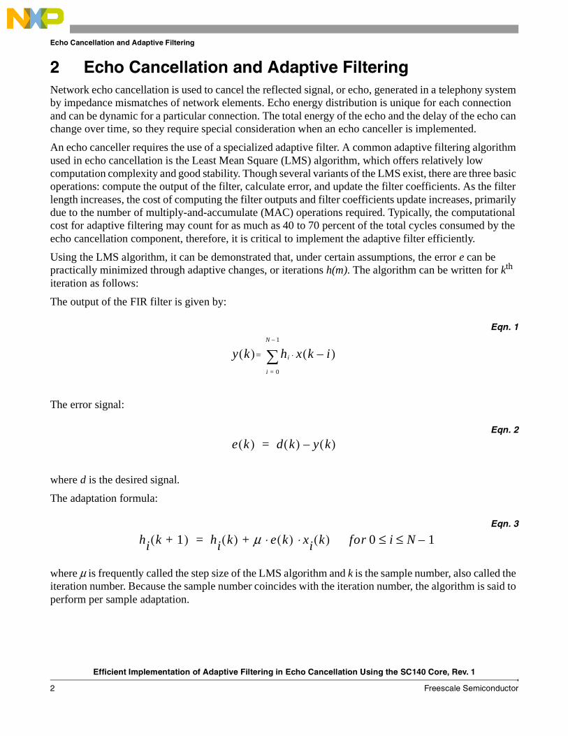
2 Echo Cancellation and Adaptive FilteringNetwork echo cancellation is used to cancel the reflected signal, or echo, generated in a telephony system by impedance mismatches of network elements. Echo energy distribution is unique for each connection and can be dynamic for a particular connection. The total energy of the echo and the delay of the echo can change over time, so they require special consideration when an echo canceller is implemented.
An echo canceller requires the use of a specialized adaptive filter. A common adaptive filtering algorithm used in echo cancellation is the Least Mean Square (LMS) algorithm, which offers relatively low computation complexity and good stability. Though several variants of the LMS exist, there are three basic operations: compute the output of the filter, calculate error, and update the filter coefficients. As the filter length increases, the cost of computing the filter outputs and filter coefficients update increases, primarily due to the number of multiply-and-accumulate (MAC) operations required. Typically, the computational cost for adaptive filtering may count for as much as 40 to 70 percent of the total cycles consumed by the echo cancellation component, therefore, it is critical to implement the adaptive filter efficiently.
Using the LMS algorithm, it can be demonstrated that, under certain assumptions, the error e can be practically minimized through adaptive changes, or iterations h(m). The algorithm can be written for kth iteration as follows:
The output of the FIR filter is given by:
Eqn. 1
The error signal:
Eqn. 2
where d is the desired signal.
The adaptation formula:
Eqn. 3
where µ is frequently called the step size of the LMS algorithm and k is the sample number, also called the iteration number. Because the sample number coincides with the iteration number, the algorithm is said to perform per sample adaptation.
y k( ) hi
i 0=
N 1–
∑= x k i–( )⋅
e k( ) d k( ) y k( )–=
hi k 1+( ) hi k( ) µ e k( ) xi k( ) for 0 i N 1–≤ ≤⋅ ⋅+=

Efficient Implementation of Adaptive Filtering in Echo Cancellation Using the SC140 Core, Rev. 1
Freescale Semiconductor 3
Adaptive Filtering on the SC140 Core
As the LMS algorithm governing equations indicate, three major computational steps are required to implement the algorithm:
• Computation of the output of the FIR filter
• Computation of error
• Computation of updated coefficients of the FIR filter
Cycle consumption for the adaptive FIR filter is dictated primarily by two operations: applying the filter and updating the filter coefficients. Using an example 256 tap filter, the FIR requires 256 MACs and 2 × 256 data moves. The update requires 256 MACS and 3 × 256 data moves.
Generally, DSPs have one to four arithmetic logic units and can move data in parallel with the arithmetic operations. Read/write and register combinations may be restricted in some architectures, limiting the efficiency of filtering operations.
3 Adaptive Filtering on the SC140 CoreDSPs have addressing modes that perform modulo address pointer updates automatically, eliminating the need to check the modulo condition in software. Some DSPs can also execute multiple data moves and arithmetic operations in parallel. Freescale StarCore-based DSPs have both modulo addressing and parallel execution. The SC140 architecture has four arithmetic logic units (ALU) and two address arithmetic units (AAU) and executes up to six instructions, including four arithmetic operations and two moves of up to 64 bits each with pointer updates (see Figure 1). For details on StarCore architecture, see the SC140 DSP Core Reference Manual.

Efficient Implementation of Adaptive Filtering in Echo Cancellation Using the SC140 Core, Rev. 1
4 Freescale Semiconductor
Adaptive Filtering on the SC140 Core
Figure 1. StarCore SC140 Block Diagram
The typical filtering application is based on the following buffered filter equation:
Eqn. 4
In real-time DSP implementations, the input x and filter coefficients h are kept in buffers of length N. As Equation 4 shows, n is not used in the indices of the input or coefficient buffers. The equation assumes that data is properly positioned within the buffers. Although the data in the coefficient buffer does not change, new input samples must be shifted into the input buffer and the oldest shifted out. Shifting the data within the buffer requires N additional moves, consuming processor cycles and decreasing efficiency. An efficient alternative to data shifting is to use modulo data pointers. As inputs are updated in the input buffer, a pointer to the oldest data with offset f is updated modulo N to wrap around the circular buffer as shown in Figure 2.
Address Generator Register File
BMU
Program Sequencer
EONCE
JTAG Controller
UnifiedData/Program Memory
ISAP
AAU
AAU
ALU
ALU
ALU
ALU
AGU
Instruction Bus
128 32 32 32 64 64
25
PDB PAB XABA XABB XDBA XDBB
DALU
DALURegister File
y n[ ] x k[ ]h N 1– k–[ ]k 0=
N 1–
∑=

Efficient Implementation of Adaptive Filtering in Echo Cancellation Using the SC140 Core, Rev. 1
Freescale Semiconductor 5
Adaptive Filtering on the SC140 Core
Figure 2. FIR Filter Buffers
The new filter equation using modulo is shown in Equation 5:
Eqn. 5
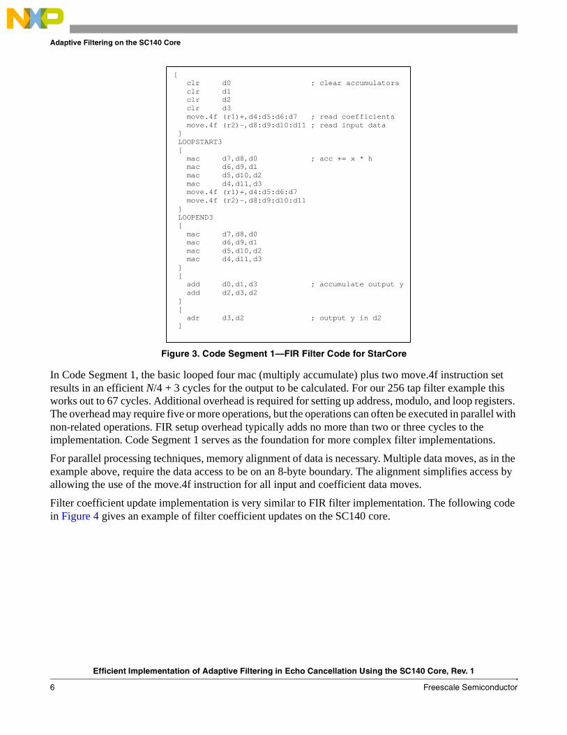
A partial implementation of an FIR filter in StarCore assembly language is shown in Figure 3. The code illustrates the sequence of arithmetic operations and data reads to compute a single output of the filter.
xN-f xN-1 x0 x1 xN-1-f… …Input Buffer
h0 hN-1h1 …Filter Buffer
offset f
y n[ ] x k f+( )modN[ ]h N 1– k–[ ]
where 0 f N≤ ≤
k 0=
N 1–
∑=
Efficient Implementation of Adaptive Filtering in Echo Cancellation Using the SC140 Core, Rev. 1
6 Freescale Semiconductor
Adaptive Filtering on the SC140 Core
Figure 3. Code Segment 1—FIR Filter Code for StarCore
In Code Segment 1, the basic looped four mac (multiply accumulate) plus two move.4f instruction set results in an efficient N/4 + 3 cycles for the output to be calculated. For our 256 tap filter example this works out to 67 cycles. Additional overhead is required for setting up address, modulo, and loop registers. The overhead may require five or more operations, but the operations can often be executed in parallel with non-related operations. FIR setup overhead typically adds no more than two or three cycles to the implementation. Code Segment 1 serves as the foundation for more complex filter implementations.
For parallel processing techniques, memory alignment of data is necessary. Multiple data moves, as in the example above, require the data access to be on an 8-byte boundary. The alignment simplifies access by allowing the use of the move.4f instruction for all input and coefficient data moves.
Filter coefficient update implementation is very similar to FIR filter implementation. The following code in Figure 4 gives an example of filter coefficient updates on the SC140 core.
[ clr d0 ; clear accumulators clr d1 clr d2 clr d3 move.4f (r1)+,d4:d5:d6:d7 ; read coefficients move.4f (r2)-,d8:d9:d10:d11 ; read input data ] LOOPSTART3 [ mac d7,d8,d0 ; acc += x * h mac d6,d9,d1 mac d5,d10,d2 mac d4,d11,d3 move.4f (r1)+,d4:d5:d6:d7 move.4f (r2)-,d8:d9:d10:d11 ] LOOPEND3 [ mac d7,d8,d0 mac d6,d9,d1 mac d5,d10,d2 mac d4,d11,d3 ] [ add d0,d1,d3 ; accumulate output y add d2,d3,d2 ] [ adr d3,d2 ; output y in d2 ]

Efficient Implementation of Adaptive Filtering in Echo Cancellation Using the SC140 Core, Rev. 1
Freescale Semiconductor 7
Adaptive Filtering on the SC140 Core
Figure 4. Code Segment 2—Update FIR Code for SC140
The SC140 core can perform four reads and four writes in a single cycle. Coefficient update requires one multiply accumulate, two reads, and one write per data. Updates require one additional memory access over the filter and, therefore, a greater number of cycles than the filter for the same filter size. The update is accomplished by performing eight multiply accumulate operations and twelve move operations per iteration of the loop. The total number of cycles for a filter of size N is 3N/8 + 1. For our 256 tap example filter, the update requires 97 cycles.
The read/write and register use combination is restricted in some architectures and may require a greater number of cycles than SC140 core. The ability to perform eight memory accesses, read or write, with four arithmetic operations and flexible register usage makes the SC140 core much more efficient at coefficient update than some other DSP architectures.
For best efficiency and code simplification, use the following guidelines when implementing an adaptive FIR filter:
• Buffer sizes should be equivalent.
• Buffer sizes should be a multiple of four.
• Align input and filter buffers on 8-byte boundaries.
• Access input buffer and filter buffer on 8-byte boundaries.
• Process four inputs and four outputs per filter iteration.
• Use the four mac and two move.4f instruction sequence for all filter computation.
• Use modulo addressing mode.
It is not always possible to follow all of these guidelines. Echo canceller requirements in particular make some of these requirements difficult.
[ move.4f (r1)+,d0:d1:d2:d3 ; load fir[0] -> fir[3] move.4f (r2)-,d4:d5:d6:d7 ; load data[ptr] ->data[ptr+3] ] FALIGN LOOPSTART1 [ macr d15,d4,d3 macr d15,d5,d2 macr d15,d6,d1 macr d15,d7,d0 move.4f (r2)-,d4:d5:d6:d7 ; load data move.4f (r1)+,d8:d9:d10:d11 ; load coefficients ] [ macr d15,d4,d11 macr d15,d5,d10 macr d15,d6,d9 macr d15,d7,d8 move.4f (r2)-,d4:d5:d6:d7 ; load data moves.4f d0:d1:d2:d3,(r3)+ ; write coefficients ] [ moves.4f d8:d9:d10:d11,(r3)+ ; write coefficients move.4f (r1)+,d0:d1:d2:d3 ; load coefficients ] LOOPEND1

Efficient Implementation of Adaptive Filtering in Echo Cancellation Using the SC140 Core, Rev. 1
8 Freescale Semiconductor
Adaptive Filtering on the SC140 Core
3.1 Filtering Requirements for ECANHigh performance programmable DSP-based echo cancellers using the LMS algorithm have special filtering requirements not found in standard filtering applications. The signal reflections handled by echo cancellers have energy within a limited time span (echo span). However, the reflection energy may be delayed anywhere from zero milliseconds to an interval several times greater than the echo span itself. The echo canceller must search the full potential delay range (echo tail span) and find the region of the reflection energy. As a result, only a portion of the filter coefficients may have significant energy. The energy is usually concentrated in a particular delay range allowing a windowed filter approach to be used. With more complex networks, the energy may exist in several delay ranges, so multiple windows must be used. Windowing provides sufficient coverage to cancel echo while eliminating the inefficiency of filtering in the negligible energy range. Echo cancellers are also required to limit response time to one millisecond per ITU G.168 standards [2]. To meet this requirement, an echo canceller must be able to filter a single input and single output.
3.1.1 Pointers and Modulo AddressingAn example high performance echo canceller can use an echo tail span of N samples and an echo span of M samples where N > M. The M sample echo span represents a windowed segment of a full N sample filter where only the windowed portion has significant energy. As the window moves to coincide with the bulk delay time of the echo, the location of the access into the coefficient buffer changes. Figure 4 shows an input buffer and a filter coefficient buffer. The input buffer contains the N newest input samples. The coefficient buffer contains N coefficients, but only M coefficients have significant energy. The region of significant energy is shifted by a delay of d.
Figure 5. Input and Filter Coefficient Buffers
Input Buffer
…
0 N - 1
Coefficient Buffer
… … …
0 d d + M - 1 N - 1

Efficient Implementation of Adaptive Filtering in Echo Cancellation Using the SC140 Core, Rev. 1
Freescale Semiconductor 9
Adaptive Filtering on the SC140 Core
The coefficient definition for windowed filtering is:
Eqn. 6
Region of significant energy:
Eqn. 7
An input data buffer for the full N sample echo tail is kept in memory, but for memory conservation a buffer of only M samples is kept for coefficients. To facilitate a shortened coefficient buffer, changes in the access point to the filter coefficients must be translated into changes in the access point to the input buffer, as demonstrated in Equation 8. In the example, d represents echo bulk delay.
The windowed filter equation is as shown in Equation 8:
Eqn. 8
Table 1 details an example of windowed filtering and lists the characteristics of the input and filter coefficients.
Table 1. Windowed FIR Filter Example
Buffer Size N = 16
Window Size M = 4
Input Offset f = 4
Bulk Delay d = 5
h i[ ] 0 for 0 i dandh i[ ] 0 for d M i Nwhere 0 d N M–≤ ≤
≤ ≤+,≅
≤ ≤,≅
h i[ ] for d i d M+<≤,
y n[ ] x k f d– N M–+ +( )mod N[ ]h d M 1– k–+[ ]
where 0 f N
and 0 d N M–≤ ≤
<≤
k 0=
M 1–
∑=
Efficient Implementation of Adaptive Filtering in Echo Cancellation Using the SC140 Core, Rev. 1
10 Freescale Semiconductor
Adaptive Filtering on the SC140 Core
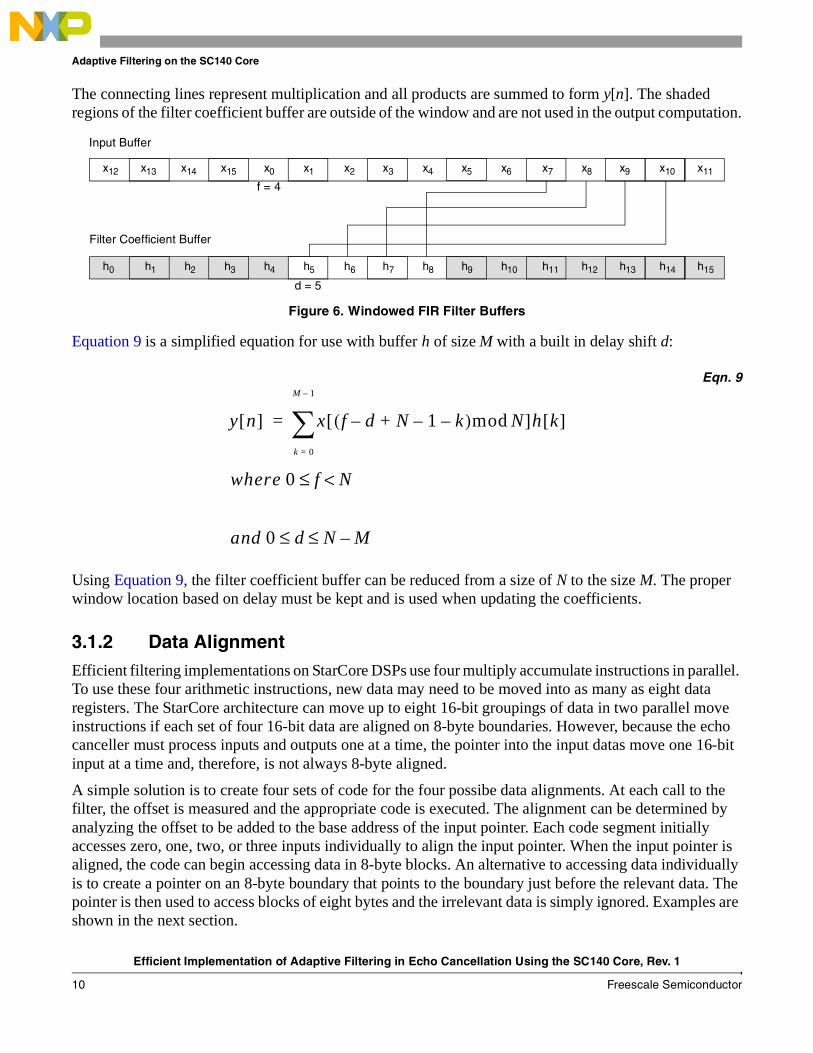
The connecting lines represent multiplication and all products are summed to form y[n]. The shaded regions of the filter coefficient buffer are outside of the window and are not used in the output computation.
Figure 6. Windowed FIR Filter Buffers
Equation 9 is a simplified equation for use with buffer h of size M with a built in delay shift d:
Eqn. 9
Using Equation 9, the filter coefficient buffer can be reduced from a size of N to the size M. The proper window location based on delay must be kept and is used when updating the coefficients.
3.1.2 Data AlignmentEfficient filtering implementations on StarCore DSPs use four multiply accumulate instructions in parallel. To use these four arithmetic instructions, new data may need to be moved into as many as eight data registers. The StarCore architecture can move up to eight 16-bit groupings of data in two parallel move instructions if each set of four 16-bit data are aligned on 8-byte boundaries. However, because the echo canceller must process inputs and outputs one at a time, the pointer into the input datas move one 16-bit input at a time and, therefore, is not always 8-byte aligned.
A simple solution is to create four sets of code for the four possibe data alignments. At each call to the filter, the offset is measured and the appropriate code is executed. The alignment can be determined by analyzing the offset to be added to the base address of the input pointer. Each code segment initially accesses zero, one, two, or three inputs individually to align the input pointer. When the input pointer is aligned, the code can begin accessing data in 8-byte blocks. An alternative to accessing data individually is to create a pointer on an 8-byte boundary that points to the boundary just before the relevant data. The pointer is then used to access blocks of eight bytes and the irrelevant data is simply ignored. Examples are shown in the next section.
x12 x13 x0x15x14 x1 x5x4x3x2 x6 x7 x10x9x8 x11
h0 h1 h4h3h2 h5 h9h8h7h6 h10 h11 h14h13h12 h15
Input Buffer
Filter Coefficient Buffer
f = 4
d = 5
y n[ ] x f d– N 1– k–+( )mod N[ ]h k[ ]
where 0 f N
and 0 d N M–≤ ≤
<≤
k 0=
M 1–
∑=

Efficient Implementation of Adaptive Filtering in Echo Cancellation Using the SC140 Core, Rev. 1
Freescale Semiconductor 11
Adaptive Filtering on the SC140 Core
3.2 Example of Windowed FIR Application and UpdateIn the example presented in this section, an FIR is first applied and then updated.
3.2.1 Apply FIRIt is helpful to create a model for the filter in C code before the assembly code version is implemented. In Code Segment 3, the windowed filter uses two buffers of size N and M where N > M. The buffer of length M is treated as a sliding window. Modulo pointer updates for input buffer x are required only when f - d > M - 1.
Figure 7. Code Segment 3–C Code for Windowed FIR
The code is split into two sections depending on where the window is placed within the buffer. In one case, the window is completely within the bounds of the buffer and no modulo is necessary. In the other case, the window wraps around the buffer and split computation is needed to handle the modulo addressing. The split computation is not necessary if hardware modulo addressing is used. Hardware-based modulo addressing is most easily implemented in assembly code.
Code Segment 1 is the base code for FIR filters, but some modifications are needed to handle data that is not 8-byte aligned. In Code Segment 3, a modified portion of the assembly code implementation is shown. This example is from one of the four sets of code described in Section 3.1.2, “Data Alignment”. The data is off alignment by four bytes. Only two of the first four data read are relevant (registers d8 and d9). The data in registers d10 and d11 is ignored. To use the move.4f instruction, the pointer must point four bytes before the start of the valid data.
acc = 0; temp = delay-offset; // -N < (delay-offset) < N-M if (temp < 0) { temp += N; // 0 < temp < N-1 } if (temp <= (N-M)) { for (k=0; k<M; k++) { acc += x[offset-delay+N-1-k] * h[k]; } } else { // temp is > (N-M) i = offset-delay+N-1; for (k=0; i>=0; k++, i--) { // from x[offset-delay+N-1] down to x[0] acc += x[i] * h[k]; } i = N-1; for (; k<M; k++,i--) { // from x[N-1] down to x[offset-delay+N-M] acc += x[i] * h[k]; } }

Efficient Implementation of Adaptive Filtering in Echo Cancellation Using the SC140 Core, Rev. 1
12 Freescale Semiconductor
Adaptive Filtering on the SC140 Core
Figure 8. Code Segment 4–Assembly Code Alignment Off by Four Bytes
Code Segment 5 is similar, but alignment is off by two bytes so only one 16-bit input is ignored.
Figure 9. Code Segment 5–Assembly Code Alignment Off by Two Bytes
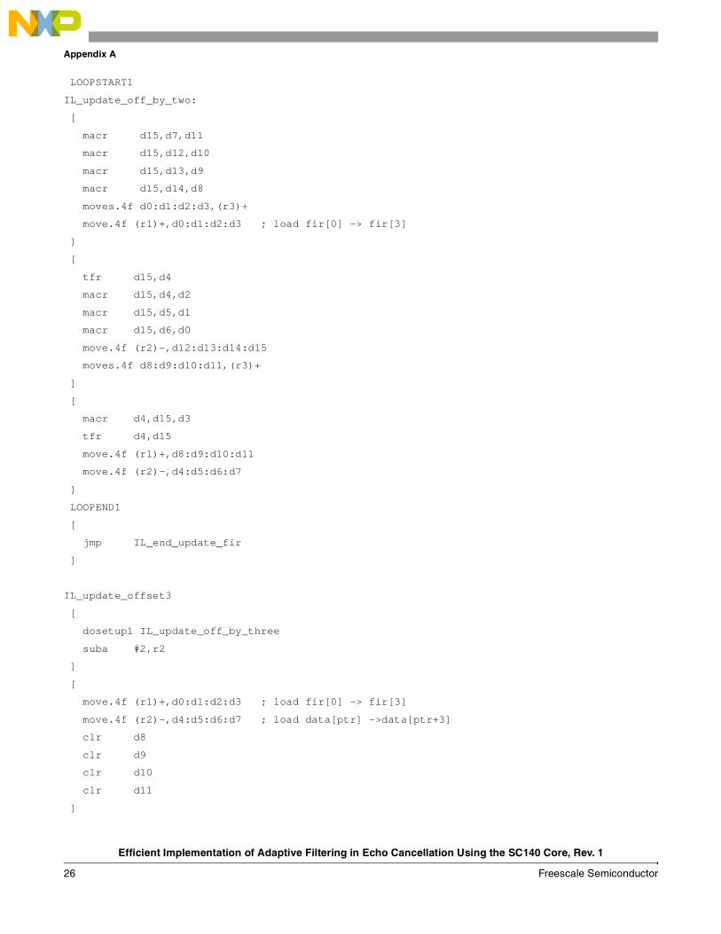
Similar code must be included after the loop to complete the execution for the remaining non-aligned data. Excess data is read again and discarded. Though extra data moves are performed, there is no increase in cycle consumption because the move.4f instruction requires only one cycle just as other data moves. Section 6, “Appendix A”, features more detailed code examples.
[ clr d0 clr d1 clr d2 clr d3 move.4f (r1)+,d4:d5:d6:d7 move.4f (r2)-,d8:d9:d10:d11 ] [ mac d5,d8,d1 mac d4,d9,d0 move.4f (r1)+,d12:d13:d14:d15 move.4f (r2)-,d8:d9:d10:d11 ] LOOPSTART3 [ mac d13,d8,d1 mac d12,d9,d0 mac d7,d10,d3 mac d6,d11,d2 move.4f (r1)+,d4:d5:d6:d7 move.4f (r2)-,d8:d9:d10:d11 ]
[ clr d0 clr d1 clr d2 clr d3 move.4f (r1)+,d4:d5:d6:d7 move.4f (r2)-,d8:d9:d10:d11 ] [ mac d6,d8,d2 mac d5,d9,d1 mac d4,d10,d0 move.4f (r1)+,d12:d13:d14:d15 move.4f (r2)-,d8:d9:d10:d11 ] LOOPSTART3 [ mac d14,d8,d2 mac d13,d9,d1 mac d12,d10,d0 mac d7,d11,d3 move.4f (r1)+,d4:d5:d6:d7 move.4f (r2)-,d8:d9:d10:d11 ]

Efficient Implementation of Adaptive Filtering in Echo Cancellation Using the SC140 Core, Rev. 1
Freescale Semiconductor 13
Adaptive Filtering on the SC140 Core
3.2.2 Update FIRIn an echo cancellation application, the LMS algorithm updates the coefficients of the FIR filter to adapt to the echo. The implementation of the FIR update is very similar to the FIR itself, with two major differences. First, where the single FIR output is the sum of products of multiply accumulate instructions, the update has an output for every multiply accumulate instruction. Thus, there is a write for each data item as opposed to a single write for each call. Second, the FIR update outputs the sum of the coefficient plus the input multiplied by a constant value. The FIR output is the sum of the product of the input and coefficients. Code Segment 6 details the update FIR implementation in C code.
Figure 10. Code Segment 6–C Code for Update Windowed FIR
The assembly code for the FIR update is also very similar to the FIR code. There are a few changes:
• The macr (multiply accumulate with round) instruction is used in place of mac because each macr result is an output.
• The moves.4f instruction is used in every iteration of the loop to write the updated filter coefficients.
• Each macr instruction has register d15, a constant value, as one of the operands.
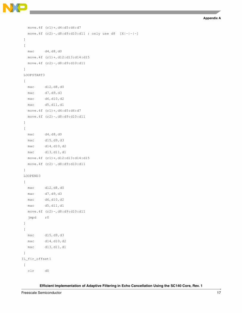
Code Segment 7 shows an example of assembly code for an update FIR where data is not 8-byte aligned.
// y is passed to the function acc = 0; temp = delay-offset; // -N < (delay-offset) < N-M if (temp < 0) { temp += N; // 0 < temp < N-1 } if (temp <= (N-M)) { for (k=0; k<M; k++) { h[k] += y * x[offset-delay+N-1-k] } } else { // temp is > (N-M) i = offset-delay+N-1; for (k=0; i>=0; k++, i--) { // from x[offset-delay+N-1] down to x[0] h[k] += y * x[i] } i = N-1; for (; k<M; k++,i--) { // from x[N-1] down to x[offset-delay+N-M] h[k] += y * x[i] } }

Efficient Implementation of Adaptive Filtering in Echo Cancellation Using the SC140 Core, Rev. 1
14 Freescale Semiconductor
Conclusion
Figure 11. Code Segment 7–Assembly Code Update FIR Not Aligned
4 ConclusionAlthough an echo canceller requires special filtering, a cycle efficient filter can be implemented with relatively little added complexity. Careful implementation allows the full use of StarCore modulo addressing, parallel read and write, and parallel arithmetic operations. Cycle consumption is comparable to a standard filter of the same size and code size is increased to approximately four times that of the standard filter if the method described in this application note is used.
[ move.4f (r1)+,d0:d1:d2:d3 ; load fir[0] -> fir[3] move.4f (r2)-,d4:d5:d6:d7 ; load data[ptr] ->data[ptr+3] ] [ tfr d15,d4 macr d15,d4,d1 macr d15,d5,d0 move.4f (r2)-,d12:d13:d14:d15 ; load data[ptr] ->data[ptr+3] dosetup1 IL_update_off_by_one ] [ tfr d4,d15 macr d4,d14,d3 macr d4,d15,d2 move.4f (r1)+,d8:d9:d10:d11 ; load fir[0] -> fir[3] move.4f (r2)-,d4:d5:d6:d7 ; load data[ptr] ->data[ptr+3] ] FALIGN LOOPSTART1 update_off_by_one: [ macr d15,d6,d11 macr d15,d7,d10 macr d15,d12,d9 macr d15,d13,d8 moves.4f d0:d1:d2:d3,(r3)+ move.4f (r1)+,d0:d1:d2:d3 ] [ tfr d15,d4 macr d15,d4,d1 macr d15,d5,d0 moves.4f d8:d9:d10:d11,(r3)+ move.4f (r2)-,d12:d13:d14:d15 ; load data[ptr] ->data[ptr+3] ] [ tfr d4,d15 macr d4,d14,d3 macr d4,d15,d2 move.4f (r2)-,d4:d5:d6:d7 ; load data[ptr] ->data[ptr+3] move.4f (r1)+,d8:d9:d10:d11 ; load fir[0] -> fir[3] ] LOOPEND1

Efficient Implementation of Adaptive Filtering in Echo Cancellation Using the SC140 Core, Rev. 1
Freescale Semiconductor 15
References
5 References1. SC140 DSP Core Reference Manual, (MNSC140CORE) Freescale Semiconductor, 2004.
2. ITU-T Recommendation G.168–Digital Network Echo Cancellers, 1997/2000/2002/2004.
3. Roman A. Dyba, Perry P. He, and Lúcio F. C. Pessoa, Network Echo Cancellers and Freescale Solutions Using the StarCore SC140 Core (AN2598).
4. Simon Haykin, Adaptive Filter Theory, Third Edition, Prentice Hall, 1997.
6 Appendix A
6.1 Apply FIR;============================ START_INLINE ====================================
;* apply_fir *
;* apply_fir (data *ec) *
;==============================================================================
[
adda #taps,r6,r1 ; for apply_fir
adda #bulk_delay,r6,r3 ; r3 points to bulk_delay
]
[
move.w (r1),d6 ; (taps)
adda #first_ref,r6,r5 ; r5 poits to first_ref
]
[
asl d6,d11 ; d11 = # of bytes for taps
asrr #>3,d6 ; d6 = taps/8
]
[
adda #data,r6,r1 ; fir_ptr = data
adda #ref_base,r6,r0
]
[
tfra r1,r2
move.w (r0),d3
]
[
move.l d3,r0
deceq d6 ; d6 = taps/8 -1
adda #echospan,r6,r8
]
[

Efficient Implementation of Adaptive Filtering in Echo Cancellation Using the SC140 Core, Rev. 1
16 Freescale Semiconductor
Appendix A
move.w (r5),d1 ; d1 = first_ref
move.w (r3),d2 ; d2 = bulk_delay
]
[
addl1a r0,r2 ; ref_ptr = data + ref_base + ...
move.w (r8),d3 ; echospan
]
[
asl d3,d3 ; (echospan)*2 size in bytes for buffer
sub d2,d1,d5 ; new_ref = new_ref - bulk_delay
push mctl
move.l #$0800,mctl ; m0 used w/ r2,
]
[
and #2,d5,d1
move.l d5,r4
move.l d3,m0 ; (echospan)*2 size in bytes for buffer
]
[
tstgt d1
and #1,d5,d1
doensh3 d6
]
[
tstgt d1
tfra r2,r10
btd IL_fir_offby23
]
[
addl1a r4,r2 ; ref_ptr = data + ref_base + new_ref
move.l #IL_fir_end_add1,r0
]
[
ift suba #2,r2
ift jmp IL_fir_offset1
]
IL_fir_offset0
[
clr d0
clr d1
clr d2
clr d3
Efficient Implementation of Adaptive Filtering in Echo Cancellation Using the SC140 Core, Rev. 1
Freescale Semiconductor 17
Appendix A
move.4f (r1)+,d4:d5:d6:d7
move.4f (r2)-,d8:d9:d10:d11 ; only use d8 [X|-|-|-]
]
[
mac d4,d8,d0
move.4f (r1)+,d12:d13:d14:d15
move.4f (r2)-,d8:d9:d10:d11
]
LOOPSTART3
[
mac d12,d8,d0
mac d7,d9,d3
mac d6,d10,d2
mac d5,d11,d1
move.4f (r1)+,d4:d5:d6:d7
move.4f (r2)-,d8:d9:d10:d11
]
[
mac d4,d8,d0
mac d15,d9,d3
mac d14,d10,d2
mac d13,d11,d1
move.4f (r1)+,d12:d13:d14:d15
move.4f (r2)-,d8:d9:d10:d11
]
LOOPEND3
[
mac d12,d8,d0
mac d7,d9,d3
mac d6,d10,d2
mac d5,d11,d1
move.4f (r2)-,d8:d9:d10:d11
jmpd r0
]
[
mac d15,d9,d3
mac d14,d10,d2
mac d13,d11,d1
]
IL_fir_offset1
[
clr d0

Efficient Implementation of Adaptive Filtering in Echo Cancellation Using the SC140 Core, Rev. 1
18 Freescale Semiconductor
Appendix A
clr d1
clr d2
clr d3
move.4f (r1)+,d4:d5:d6:d7 ; load fir[0] -> fir[3]
move.4f (r2)-,d8:d9:d10:d11 ; only use d8 & d9 [Y|X|-|-]
]
[
mac d5,d8,d1
mac d4,d9,d0
move.4f (r1)+,d12:d13:d14:d15
move.4f (r2)-,d8:d9:d10:d11
]
LOOPSTART3
[
mac d13,d8,d1
mac d12,d9,d0
mac d7,d10,d3
mac d6,d11,d2
move.4f (r1)+,d4:d5:d6:d7
move.4f (r2)-,d8:d9:d10:d11
]
[
mac d5,d8,d1
mac d4,d9,d0
mac d15,d10,d3
mac d14,d11,d2
move.4f (r1)+,d12:d13:d14:d15
move.4f (r2)-,d8:d9:d10:d11
]
LOOPEND3
[
mac d13,d8,d1
mac d12,d9,d0
mac d7,d10,d3
mac d6,d11,d2
move.4f (r2)-,d8:d9:d10:d11
jmpd r0
]
[
mac d15,d10,d3
mac d14,d11,d2
]

Efficient Implementation of Adaptive Filtering in Echo Cancellation Using the SC140 Core, Rev. 1
Freescale Semiconductor 19
Appendix A
IL_fir_offby23
[
bt IL_fir_offset3
suba #4,r2
]
IL_fir_offset2
[
clr d0
clr d1
clr d2
clr d3
move.4f (r1)+,d4:d5:d6:d7 ; load fir[0] -> fir[3]
move.4f (r2)-,d8:d9:d10:d11 ; only use d8,d9 & d10 [Z|Y|X|-]
]
[
mac d6,d8,d2
mac d5,d9,d1
mac d4,d10,d0
move.4f (r1)+,d12:d13:d14:d15
move.4f (r2)-,d8:d9:d10:d11
]
LOOPSTART3
[
mac d14,d8,d2
mac d13,d9,d1
mac d12,d10,d0
mac d7,d11,d3
move.4f (r1)+,d4:d5:d6:d7
move.4f (r2)-,d8:d9:d10:d11
]
[
mac d6,d8,d2
mac d5,d9,d1
mac d4,d10,d0
mac d15,d11,d3
move.4f (r1)+,d12:d13:d14:d15
move.4f (r2)-,d8:d9:d10:d11
]
LOOPEND3
[
mac d14,d8,d2
mac d13,d9,d1
Efficient Implementation of Adaptive Filtering in Echo Cancellation Using the SC140 Core, Rev. 1
20 Freescale Semiconductor
Appendix A
mac d12,d10,d0
mac d7,d11,d3
move.4f (r2)-,d8:d9:d10:d11
jmpd r0
]
mac d15,d11,d3
IL_fir_offset3
suba #2,r2 ; sub #6
[
clr d0
clr d1
clr d2
clr d3
move.4f (r1)+,d4:d5:d6:d7 ; load fir[0] -> fir[3]
move.4f (r2)-,d8:d9:d10:d11 ; use d8,d9,d10,d11 [A|Z|Y|X]
]
[
mac d7,d8,d0
mac d6,d9,d1
mac d5,d10,d2
mac d4,d11,d3
move.4f (r2)-,d8:d9:d10:d11
move.4f (r1)+,d4:d5:d6:d7
]
LOOPSTART3
[
mac d7,d8,d3
mac d6,d9,d2
mac d5,d10,d1
mac d4,d11,d0
move.4f (r1)+,d4:d5:d6:d7
move.4f (r2)-,d8:d9:d10:d11
]
[
mac d7,d8,d3
mac d6,d9,d2
mac d5,d10,d1
mac d4,d11,d0
move.4f (r1)+,d4:d5:d6:d7
move.4f (r2)-,d8:d9:d10:d11
]
LOOPEND3

Efficient Implementation of Adaptive Filtering in Echo Cancellation Using the SC140 Core, Rev. 1
Freescale Semiconductor 21
Appendix A
[
mac d7,d8,d3
mac d6,d9,d2
mac d5,d10,d1
mac d4,d11,d0
]
IL_fir_end_add1
[
add d0,d1,d0
add d2,d3,d2
]
IL_fir_end_add2
[
add d0,d2,d0
pop mctl
]
nop ; MCTL Stall
[
rnd d0,d2
]
;==============================================================================
;* end apply_fir *
;==============================================================================
6.2 Update FIR;==============================================================================
;* update_fir *
;* update_fir (data *ec, const Word16 y) *
;==============================================================================
[
adda #taps,r6,r5 ; r5 points to # of taps
adda #bulk_delay,r6,r3 ; r3 points to bulk_delay
]
[
move.w (r3),d2 ; d2 = bulk_delay
move.w (r5),d0 ; d0 = taps
]
adda #first_ref,r6,r5 ; r2 points to first_ref
[
move.w (r5),d1 ; d1 = first_ref
add #2,d3
adda #ref_base,r6,r0
Efficient Implementation of Adaptive Filtering in Echo Cancellation Using the SC140 Core, Rev. 1
22 Freescale Semiconductor
Appendix A
]
[
adda #data,r6,r1 ; fir_ptr = data
move.w (r0),d4
]
[
move.l d4,r0
adda #echospan,r6,r8
]
[
tfra r1,r2
sub d2,d1,d5 ; d5 = first_ref - (bulk_delay)
move.w (r8),d4 ; echospan
]
[
push mctl
asl d5,d6 ; d5 = new_ref in bytes
and d5,d3
addl1a r0,r2 ; ref_ptr = data + ref_base + ...
asl d4,d4 ; (echospan)*2 size in bytes for buffer
]
[
move.l d4,m0 ; (echospan)*2 size in bytes for buffer
move.l #$0800,mctl ; m0 used with r2
]
nop ; MCTL Stall
[
move.l d6,r4
tfra r2,r10
tstgt d3
and #01,d5,d1
]
[
btd IL_update_offset2or3
tstgt d1
doen1 d0
]
[
adda r4,r2
tfra r1,r3 ; transfer r1 to r3, for storing updated FIR
]
[
Efficient Implementation of Adaptive Filtering in Echo Cancellation Using the SC140 Core, Rev. 1
Freescale Semiconductor 23
Appendix A
ift jmp IL_update_offset1
ift suba #2,r2
]
IL_update_offset0or1
[
move.4f (r1)+,d0:d1:d2:d3 ; load fir[0] -> fir[3]
move.4f (r2)-,d4:d5:d6:d7 ; load data[ptr] ->data[ptr+3]
]
[
tfr d15,d4
macr d15,d4,d0
move.4f (r2)-,d12:d13:d14:d15 ; load data[ptr] ->data[ptr+3]
dosetup1 IL_update_off_by_zero
]
[
tfr d4,d15
macr d4,d13,d3
macr d4,d14,d2
macr d4,d15,d1
move.4f (r2)-,d4:d5:d6:d7 ; load data[ptr] ->data[ptr+3]
move.4f (r1)+,d8:d9:d10:d11
]
FALIGN
LOOPSTART1
IL_update_off_by_zero:
[
macr d15,d5,d11
macr d15,d6,d10
macr d15,d7,d9
macr d15,d12,d8
moves.4f d0:d1:d2:d3,(r3)+
move.4f (r1)+,d0:d1:d2:d3 ; load fir[0] -> fir[3]
]
[
tfr d15,d4
macr d15,d4,d0
move.4f (r2)-,d12:d13:d14:d15 ; load data[ptr] ->data[ptr+3]
moves.4f d8:d9:d10:d11,(r3)+
]
[
tfr d4,d15
macr d4,d13,d3

Efficient Implementation of Adaptive Filtering in Echo Cancellation Using the SC140 Core, Rev. 1
24 Freescale Semiconductor
Appendix A
macr d4,d14,d2
macr d4,d15,d1
move.4f (r1)+,d8:d9:d10:d11
move.4f (r2)-,d4:d5:d6:d7 ; load data[ptr] ->data[ptr+3]
]
LOOPEND1
[
jmp IL_end_update_fir
]
IL_update_offset1
[
move.4f (r1)+,d0:d1:d2:d3 ; load fir[0] -> fir[3]
move.4f (r2)-,d4:d5:d6:d7 ; load data[ptr] ->data[ptr+3]
]
[
tfr d15,d4
macr d15,d4,d1
macr d15,d5,d0
move.4f (r2)-,d12:d13:d14:d15 ; load data[ptr] ->data[ptr+3]
dosetup1 IL_update_off_by_one
]
[
tfr d4,d15
macr d4,d14,d3
macr d4,d15,d2
move.4f (r1)+,d8:d9:d10:d11 ; load fir[0] -> fir[3]
move.4f (r2)-,d4:d5:d6:d7 ; load data[ptr] ->data[ptr+3]
]
FALIGN
LOOPSTART1
IL_update_off_by_one:
[
macr d15,d6,d11
macr d15,d7,d10
macr d15,d12,d9
macr d15,d13,d8
moves.4f d0:d1:d2:d3,(r3)+
move.4f (r1)+,d0:d1:d2:d3
]
[
tfr d15,d4
macr d15,d4,d1
Efficient Implementation of Adaptive Filtering in Echo Cancellation Using the SC140 Core, Rev. 1
Freescale Semiconductor 25
Appendix A
macr d15,d5,d0
moves.4f d8:d9:d10:d11,(r3)+
move.4f (r2)-,d12:d13:d14:d15 ; load data[ptr] ->data[ptr+3]
]
[
tfr d4,d15
macr d4,d14,d3
macr d4,d15,d2
move.4f (r2)-,d4:d5:d6:d7 ; load data[ptr] ->data[ptr+3]
move.4f (r1)+,d8:d9:d10:d11 ; load fir[0] -> fir[3]
]
LOOPEND1
[
jmp IL_end_update_fir
]
IL_update_offset2or3
[
bt IL_update_offset3
suba #4,r2
]
IL_update_offset2
[
dosetup1 IL_update_off_by_two
]
[
move.4f (r1)+,d0:d1:d2:d3 ; load fir[0] -> fir[3]
move.4f (r2)-,d4:d5:d6:d7 ; load data[ptr] ->data[ptr+3]
]
[
tfr d15,d4
macr d15,d4,d2
macr d15,d5,d1
macr d15,d6,d0
move.4f (r2)-,d12:d13:d14:d15 ; load data[ptr] ->data[ptr+3]
]
[
tfr d4,d15
macr d4,d15,d3
move.4f (r2)-,d4:d5:d6:d7 ; load data[ptr] ->data[ptr+3]
move.4f (r1)+,d8:d9:d10:d11 ; load fir[0] -> fir[3]
]
FALIGN
Efficient Implementation of Adaptive Filtering in Echo Cancellation Using the SC140 Core, Rev. 1
26 Freescale Semiconductor
Appendix A
LOOPSTART1
IL_update_off_by_two:
[
macr d15,d7,d11
macr d15,d12,d10
macr d15,d13,d9
macr d15,d14,d8
moves.4f d0:d1:d2:d3,(r3)+
move.4f (r1)+,d0:d1:d2:d3 ; load fir[0] -> fir[3]
]
[
tfr d15,d4
macr d15,d4,d2
macr d15,d5,d1
macr d15,d6,d0
move.4f (r2)-,d12:d13:d14:d15
moves.4f d8:d9:d10:d11,(r3)+
]
[
macr d4,d15,d3
tfr d4,d15
move.4f (r1)+,d8:d9:d10:d11
move.4f (r2)-,d4:d5:d6:d7
]
LOOPEND1
[
jmp IL_end_update_fir
]
IL_update_offset3
[
dosetup1 IL_update_off_by_three
suba #2,r2
]
[
move.4f (r1)+,d0:d1:d2:d3 ; load fir[0] -> fir[3]
move.4f (r2)-,d4:d5:d6:d7 ; load data[ptr] ->data[ptr+3]
clr d8
clr d9
clr d10
clr d11
]

Efficient Implementation of Adaptive Filtering in Echo Cancellation Using the SC140 Core, Rev. 1
Freescale Semiconductor 27
Appendix A
FALIGN
LOOPSTART1
IL_update_off_by_three:
[
macr d15,d4,d3
macr d15,d5,d2
macr d15,d6,d1
macr d15,d7,d0
move.4f (r2)-,d4:d5:d6:d7
move.4f (r1)+,d8:d9:d10:d11
]
[
macr d15,d4,d11
macr d15,d5,d10
macr d15,d6,d9
macr d15,d7,d8
move.4f (r2)-,d4:d5:d6:d7
moves.4f d0:d1:d2:d3,(r3)+
]
[
moves.4f d8:d9:d10:d11,(r3)+
move.4f (r1)+,d0:d1:d2:d3
]
LOOPEND1
IL_end_update_fir
[
pop mctl
]
;==============================================================================
;* end update_fir *
;==============================================================================

Document Number: AN3064Rev. 104/2006
Freescale™ and the Freescale logo are trademarks of Freescale Semiconductor, Inc. StarCore is a licensed trademark of StarCore LLC. All other product or service names are the property of their respective owners.
© Freescale Semiconductor, Inc., 2004, 2006.
Information in this document is provided solely to enable system and software
implementers to use Freescale Semiconductor products. There are no express or
implied copyright licenses granted hereunder to design or fabricate any integrated
circuits or integrated circuits based on the information in this document.
Freescale Semiconductor reserves the right to make changes without further notice to
any products herein. Freescale Semiconductor makes no warranty, representation or
guarantee regarding the suitability of its products for any particular purpose, nor does
Freescale Semiconductor assume any liability arising out of the application or use of
any product or circuit, and specifically disclaims any and all liability, including without
limitation consequential or incidental damages. “Typical” parameters which may be
provided in Freescale Semiconductor data sheets and/or specifications can and do
vary in different applications and actual performance may vary over time. All operating
parameters, including “Typicals” must be validated for each customer application by
customer’s technical experts. Freescale Semiconductor does not convey any license
under its patent rights nor the rights of others. Freescale Semiconductor products are
not designed, intended, or authorized for use as components in systems intended for
surgical implant into the body, or other applications intended to support or sustain life,
or for any other application in which the failure of the Freescale Semiconductor product
could create a situation where personal injury or death may occur. Should Buyer
purchase or use Freescale Semiconductor products for any such unintended or
unauthorized application, Buyer shall indemnify and hold Freescale Semiconductor
and its officers, employees, subsidiaries, affiliates, and distributors harmless against all
claims, costs, damages, and expenses, and reasonable attorney fees arising out of,
directly or indirectly, any claim of personal injury or death associated with such
unintended or unauthorized use, even if such claim alleges that Freescale
Semiconductor was negligent regarding the design or manufacture of the part.
How to Reach Us:
Home Page: www.freescale.com
email: [email protected]
USA/Europe or Locations Not Listed: Freescale Semiconductor Technical Information Center, CH3701300 N. Alma School Road Chandler, Arizona 85224 (800) [email protected]
Europe, Middle East, and Africa:Freescale Halbleiter Deutschland GmbHTechnical Information CenterSchatzbogen 781829 Muenchen, Germany+44 1296 380 456 (English) +46 8 52200080 (English)+49 89 92103 559 (German)+33 1 69 35 48 48 (French) [email protected]
Japan: Freescale Semiconductor Japan Ltd. HeadquartersARCO Tower 15F1-8-1, Shimo-Meguro, Meguro-ku Tokyo 153-0064, Japan 0120 191014+81 2666 [email protected]
Asia/Pacific: Freescale Semiconductor Hong Kong Ltd. Technical Information Center2 Dai King Street Tai Po Industrial Estate, Tai Po, N.T., Hong Kong +800 2666 [email protected]
For Literature Requests Only:Freescale Semiconductor
Literature Distribution Center P.O. Box 5405Denver, Colorado 80217 (800) 441-2447303-675-2140Fax: 303-675-2150LDCForFreescaleSemiconductor
@hibbertgroup.com
Related Documents


