ammonia would react directly with com- pounds 4a and 4b, and a dissociative path D, in which ammonia would react with a 14- electron complex formed after dissociation of olefin (Scheme 5). The rates of decay of the pentene complex 4b were measured by 31 P NMR spectroscopy with varied amounts of olefin and ratios of ammonia to olefin (data and plot are shown in figs. S1 and S2 and table S1). The observable rate constants, k obs , predicted for reaction by associative path C (Eq. 1) and dissociative path D (Eq. 2), were derived with the steady state approximation. For path C, the observed rate constant would be independent of the con- centration of olefin, but for path D, a plot of 1/k obs versus the ratio of olefin to ammonia is predicted to be linear with a nonzero intercept. The reactions were clearly slower at higher concentrations of olefin, and a plot of 1/k obs versus the ratio of olefin to ammonia was found to be linear with a positive slope (0.20 10 –4 T 0.01 10 –4 s –1 ) and a nonzero y intercept (0.65 10 –4 T 0.16 10 –4 s). These data suggest that olefin dissociation is the first step in the reaction, and, if so, the y intercept of this double reciprocal plot would correspond to the inverse of the rate constant for dissociation of olefin. 1 k obs 0 k j1 k 1 k 2 Eammonia^ þ 1 k 1 Eammonia^ ð1Þ 1 k obs 0 k j1 Epentene^ k 1 k 2 Eammonia^ þ 1 k 1 ð2Þ Because substitution reaction of square- planar d 8 complexes typically proceed associ- atively, and because the reactions could occur by more complex pathways with multiple equilibria preceding N-H bond cleavage, we conducted further experiments to test whether the reaction was initiated by dissociation of olefin. The pentene in complex 4b is dis- placed by ethylene to form ethylene complex 4c. If the reactions of 4b occur dissociatively, then the rate constants for dissociation of pentene obtained from the reaction of 4b with ethylene and from the reaction of 4b with ammonia should be the same. Consistent with dissociative reactions of 4b, the reaction of 4b with ethylene was independent of the concentration of ethylene or 0.03 to 0.3 M added pentene; all reactions occurred with rate constants within 3% of the mean value of 1.6 10 j3 . Moreover, this mean value is well within experimental error of the value of k 1 (1.5 10 j3 ) measured for the reaction of ammonia with 4b. The identification of an iridium complex that undergoes oxidative addition of ammonia and the elucidation of key thermodynamic and mechanistic aspects of the reaction advance our understanding of how to cleave N-H bonds under mild conditions. We antic- ipate that this understanding will accelerate the development of catalytic chemistry that parallels the existing reactions of hydrogen, hydrocarbons, silanes, and boranes but begins with oxidative addition of the N-H bond of abundant and inexpensive ammonia. References and Notes 1. G. B. Kauffman, in Coordination Chemistry: A Century of Progress. (American Chemical Society Symposium Series, Washington, DC, 1994), vol. 565, pp. 3–34. 2. Two reactions of ammonia are among the top 10 challenges for catalysis listed in this article: J. Haggin, Chem. Eng. News. 71, 23 (1993). 3. For a reaction of an Ir(I) complex with ammonia to form an insoluble product containing hydrides and bridging amides, as characterized by solid-state IR and 1 H NMR spectroscopy and derivatization, see A. L. Casalnuovo, J. C. Calabrese, D. Milstein, Inorg. Chem. 26, 971 (1987). 4. For the protonolysis of a hydride ligand on a group IV metal complex, presumably after coordination of the ammonia ligand, see G. L. Hillhouse, J. E. Bercaw, J. Am. Chem. Soc. 106, 5472 (1984). 5. For an example of a reaction of ammonia with a cluster to form a product in low yield that was formulated by 1 H NMR spectroscopy to contain a bridging hydride and bridging amide, see E. G. Bryan, B. F. G. Johnson, J. Lewis, J. Chem. Soc. Dalton Trans. 1977, 1328 (1977). 6. F. L. Joslin, M. P. Johnson, J. T. Mague, D. M. Roundhill, Organometallics 10, 2781 (1991). 7. A. W. Kaplan, J. C. M. Ritter, R. G. Bergman, J. Am. Chem. Soc. 120, 6828 (1998). 8. J. Campora, P. Palma, D. del Rio, M. M. Conejo, E. Alvarez, Organometallics 23, 5653 (2004). 9. D. Conner, K. N. Jayaprakash, T. R. Cundari, T. B. Gunnoe, Organometallics 23, 2724 (2004). 10. H. E. Bryndza, W. Tam, Chem. Rev. 88, 1163 (1988). 11. J. R. Fulton, A. W. Holland, D. J. Fox, R. G. Bergman, Acc. Chem. Res. 35, 44 (2002). 12. J. R. Fulton, S. Sklenak, M. W. Bouwkamp, R. G. Bergman, J. Am. Chem. Soc. 124, 4722 (2002). 13. D. J. Fox, R. G. Bergman, Organometallics 23, 1656 (2004). 14. M. Kanzelberger, B. Singh, M. Czerw, K. Krogh-Jespersen, A. S. Goldman, J. Am. Chem. Soc. 122, 11017 (2000). 15. D. Morales-Morales, D. W. Lee, Z. Wang, C. M. Jensen, Organometallics 20, 1144 (2001). 16. M. Kanzelberger et al., J. Am. Chem. Soc. 125, 13644 (2003). 17. K. Krogh-Jesperson et al., J. Am. Chem. Soc. 124, 10797 (2002). 18. N. A. Al-Salem, H. D. Empsall, R. Markham, B. L. Shaw, B. Weeks, J. Chem. Soc. Dalton Trans. 1979, 1972 (1979). 19. M. A. McLoughlin, R. J. Flesher, W. C. Kaska, H. A. Mayer, Organometallics 13, 3816 (1994). 20. Materials and methods, including the details of the synthesis of the olefin complexes, are available as supporting material on Science Online. 21. J. F. Riehl, Y. Jean, O. Eisenstein, M. Pelissier, Organo- metallics 11, 729 (1992). 22. J. F. Hartwig, R. G. Bergman, R. A. Andersen, J. Am. Chem. Soc. 113, 3404 (1991). 23. J. Ruiz, V. Rodriguez, G. Lopez, P. A. Chaloner, P. B. Hitchcock, J. Chem. Soc. Dalton Trans. 1997, 4271 (1997). 24. M. Kanzelberger et al., J. Am. Chem. Soc. 125, 13644 (2003). 25. P. L. Holland, R. A. Andersen, R. G. Bergman, J. K. Huang, S. P. Nolan, J. Am. Chem. Soc. 119, 12800 (1997). 26. H. A. Y. Mohammad et al., Organometallics 21, 5775 (2002). 27. H. D. Empsall et al., J. Chem. Soc. Chem. Commun. 1977, 589 (1977). 28. C. Crocker et al., J. Chem. Soc. Dalton Trans. 1982, 1217 (1982). 29. This method would detect deuterium in the ligand if it were present in 10% of the sample. 30. We thank the Department of Energy for funding. Structural data for compounds 4a and 5 have been deposited in the Cambridge Crystallographic Data Centre under CCDC 260224 (4a) and 260225 (5), and can be obtained free of charge at www.ccdc.cam. ac.uk/conts/retrieving.html. We thank L. Bienen for editing of the manuscript. Supporting Online Material www.sciencemag.org/cgi/content/full/307/5712/1080/ DC1 Materials and Methods Figs. S1 to S5 Tables S1 to S6 References and Notes 1 December 2004; accepted 12 January 2005 10.1126/science.1109389 Efficient Bipedal Robots Based on Passive-Dynamic Walkers Steve Collins, 1 Andy Ruina, 2 * Russ Tedrake, 3 Martijn Wisse 4 Passive-dynamic walkers are simple mechanical devices, composed of solid parts connected by joints, that walk stably down a slope. They have no motors or controllers, yet can have remarkably humanlike motions. This suggests that these machines are useful models of human locomotion; however, they cannot walk on level ground. Here we present three robots based on passive-dynamics, with small active power sources substituted for gravity, which can walk on level ground. These robots use less control and less energy than other powered robots, yet walk more naturally, further suggesting the importance of passive-dynamics in human locomotion. Most researchers study human locomotion by observing people as they walk, measuring joint angles and ground reaction forces (1). Our approach is different: We study human locomotion by designing and testing walking machines that we compare to humans in terms of morphology, gait appearance, ener- gy use, and control. Previous bipedal robots with humanlike forms have demonstrated smooth, versatile motions (2–5). These impressive robots are based on the mainstream control paradigm, namely, precise joint-angle control. For the study of human walking, this control para- digm is unsatisfactory, because it requires actuators with higher precision and frequen- R EPORTS 18 FEBRUARY 2005 VOL 307 SCIENCE www.sciencemag.org 1082

Welcome message from author
This document is posted to help you gain knowledge. Please leave a comment to let me know what you think about it! Share it to your friends and learn new things together.
Transcript

ammonia would react directly with com-
pounds 4a and 4b, and a dissociative path D,
in which ammonia would react with a 14-
electron complex formed after dissociation
of olefin (Scheme 5). The rates of decay of
the pentene complex 4b were measured by31P NMR spectroscopy with varied amounts
of olefin and ratios of ammonia to olefin
(data and plot are shown in figs. S1 and S2
and table S1). The observable rate constants,
kobs
, predicted for reaction by associative
path C (Eq. 1) and dissociative path D (Eq.
2), were derived with the steady state
approximation. For path C, the observed rate
constant would be independent of the con-
centration of olefin, but for path D, a plot
of 1/kobs
versus the ratio of olefin to ammonia
is predicted to be linear with a nonzero
intercept. The reactions were clearly slower
at higher concentrations of olefin, and a plot
of 1/kobs
versus the ratio of olefin to ammonia
was found to be linear with a positive slope
(0.20 � 10–4 T 0.01 � 10–4 s–1) and a nonzero
y intercept (0.65 � 10–4 T 0.16 � 10–4 s).
These data suggest that olefin dissociation
is the first step in the reaction, and, if so, the
y intercept of this double reciprocal plot
would correspond to the inverse of the rate
constant for dissociation of olefin.
1
kobs
0kj1
k1k
2Eammonia^
þ 1
k1Eammonia^
ð1Þ
1
kobs
0kj1Epentene^
k1k2Eammonia^þ 1
k1
ð2Þ
Because substitution reaction of square-
planar d8 complexes typically proceed associ-
atively, and because the reactions could occur
by more complex pathways with multiple
equilibria preceding N-H bond cleavage, we
conducted further experiments to test whether
the reaction was initiated by dissociation of
olefin. The pentene in complex 4b is dis-
placed by ethylene to form ethylene complex
4c. If the reactions of 4b occur dissociatively,
then the rate constants for dissociation of
pentene obtained from the reaction of 4b with
ethylene and from the reaction of 4b with
ammonia should be the same.
Consistent with dissociative reactions of
4b, the reaction of 4b with ethylene was
independent of the concentration of ethylene
or 0.03 to 0.3 M added pentene; all reactions
occurred with rate constants within 3% of the
mean value of 1.6 � 10j3. Moreover, this
mean value is well within experimental error
of the value of k1
(1.5 � 10j3) measured for
the reaction of ammonia with 4b.
The identification of an iridium complex
that undergoes oxidative addition of ammonia
and the elucidation of key thermodynamic
and mechanistic aspects of the reaction
advance our understanding of how to cleave
N-H bonds under mild conditions. We antic-
ipate that this understanding will accelerate
the development of catalytic chemistry that
parallels the existing reactions of hydrogen,
hydrocarbons, silanes, and boranes but begins
with oxidative addition of the N-H bond of
abundant and inexpensive ammonia.
References and Notes1. G. B. Kauffman, in Coordination Chemistry: A Century
of Progress. (American Chemical Society SymposiumSeries, Washington, DC, 1994), vol. 565, pp. 3–34.
2. Two reactions of ammonia are among the top 10challenges for catalysis listed in this article: J. Haggin,Chem. Eng. News. 71, 23 (1993).
3. For a reaction of an Ir(I) complex with ammonia toform an insoluble product containing hydrides andbridging amides, as characterized by solid-state IRand 1H NMR spectroscopy and derivatization, seeA. L. Casalnuovo, J. C. Calabrese, D. Milstein, Inorg.Chem. 26, 971 (1987).
4. For the protonolysis of a hydride ligand on a groupIV metal complex, presumably after coordination ofthe ammonia ligand, see G. L. Hillhouse, J. E. Bercaw,J. Am. Chem. Soc. 106, 5472 (1984).
5. For an example of a reaction of ammonia with acluster to form a product in low yield that wasformulated by 1H NMR spectroscopy to contain abridging hydride and bridging amide, see E. G. Bryan,B. F. G. Johnson, J. Lewis, J. Chem. Soc. Dalton Trans.1977, 1328 (1977).
6. F. L. Joslin, M. P. Johnson, J. T. Mague, D. M. Roundhill,Organometallics 10, 2781 (1991).
7. A. W. Kaplan, J. C. M. Ritter, R. G. Bergman, J. Am.Chem. Soc. 120, 6828 (1998).
8. J. Campora, P. Palma, D. del Rio, M. M. Conejo, E.Alvarez, Organometallics 23, 5653 (2004).
9. D. Conner, K. N. Jayaprakash, T. R. Cundari, T. B.Gunnoe, Organometallics 23, 2724 (2004).
10. H. E. Bryndza, W. Tam, Chem. Rev. 88, 1163 (1988).11. J. R. Fulton, A. W. Holland, D. J. Fox, R. G. Bergman,
Acc. Chem. Res. 35, 44 (2002).12. J. R. Fulton, S. Sklenak, M. W. Bouwkamp, R. G.
Bergman, J. Am. Chem. Soc. 124, 4722 (2002).13. D. J. Fox, R. G. Bergman, Organometallics 23, 1656
(2004).14. M. Kanzelberger, B. Singh, M. Czerw, K. Krogh-Jespersen,
A. S. Goldman, J. Am. Chem. Soc. 122, 11017 (2000).
15. D. Morales-Morales, D. W. Lee, Z. Wang, C. M.Jensen, Organometallics 20, 1144 (2001).
16. M. Kanzelberger et al., J. Am. Chem. Soc. 125, 13644(2003).
17. K. Krogh-Jesperson et al., J. Am. Chem. Soc. 124,10797 (2002).
18. N. A. Al-Salem, H. D. Empsall, R. Markham, B. L.Shaw, B. Weeks, J. Chem. Soc. Dalton Trans. 1979,1972 (1979).
19. M. A. McLoughlin, R. J. Flesher, W. C. Kaska, H. A.Mayer, Organometallics 13, 3816 (1994).
20. Materials and methods, including the details of thesynthesis of the olefin complexes, are available assupporting material on Science Online.
21. J. F. Riehl, Y. Jean, O. Eisenstein, M. Pelissier, Organo-metallics 11, 729 (1992).
22. J. F. Hartwig, R. G. Bergman, R. A. Andersen, J. Am.Chem. Soc. 113, 3404 (1991).
23. J. Ruiz, V. Rodriguez, G. Lopez, P. A. Chaloner, P. B.Hitchcock, J. Chem. Soc. Dalton Trans. 1997, 4271(1997).
24. M. Kanzelberger et al., J. Am. Chem. Soc. 125, 13644(2003).
25. P. L. Holland, R. A. Andersen, R. G. Bergman, J. K. Huang,S. P. Nolan, J. Am. Chem. Soc. 119, 12800 (1997).
26. H. A. Y. Mohammad et al., Organometallics 21, 5775(2002).
27. H. D. Empsall et al., J. Chem. Soc. Chem. Commun.1977, 589 (1977).
28. C. Crocker et al., J. Chem. Soc. Dalton Trans. 1982,1217 (1982).
29. This method would detect deuterium in the ligand ifit were present in 10% of the sample.
30. We thank the Department of Energy for funding.Structural data for compounds 4a and 5 have beendeposited in the Cambridge Crystallographic DataCentre under CCDC 260224 (4a) and 260225 (5),and can be obtained free of charge at www.ccdc.cam.ac.uk/conts/retrieving.html. We thank L. Bienen forediting of the manuscript.
Supporting Online Materialwww.sciencemag.org/cgi/content/full/307/5712/1080/DC1Materials and MethodsFigs. S1 to S5Tables S1 to S6References and Notes
1 December 2004; accepted 12 January 200510.1126/science.1109389
Efficient Bipedal Robots Based onPassive-Dynamic Walkers
Steve Collins,1 Andy Ruina,2* Russ Tedrake,3 Martijn Wisse4
Passive-dynamic walkers are simple mechanical devices, composed of solidparts connected by joints, that walk stably down a slope. They have nomotors or controllers, yet can have remarkably humanlike motions. Thissuggests that these machines are useful models of human locomotion;however, they cannot walk on level ground. Here we present three robotsbased on passive-dynamics, with small active power sources substituted forgravity, which can walk on level ground. These robots use less control and lessenergy than other powered robots, yet walk more naturally, furthersuggesting the importance of passive-dynamics in human locomotion.
Most researchers study human locomotion
by observing people as they walk, measuring
joint angles and ground reaction forces (1).
Our approach is different: We study human
locomotion by designing and testing walking
machines that we compare to humans in
terms of morphology, gait appearance, ener-
gy use, and control.
Previous bipedal robots with humanlike
forms have demonstrated smooth, versatile
motions (2–5). These impressive robots are
based on the mainstream control paradigm,
namely, precise joint-angle control. For the
study of human walking, this control para-
digm is unsatisfactory, because it requires
actuators with higher precision and frequen-
R E P O R T S
18 FEBRUARY 2005 VOL 307 SCIENCE www.sciencemag.org1082
Andy Ruina
Rectangle
Andy Ruina
Rectangle
cy response than human muscles have (6)
and requires an order of magnitude more
energy. To address these issues, passive-
dynamic walkers (Fig. 1) were proposed as
a new design and control paradigm (7). In
contrast to mainstream robots, which actively
control every joint angle at all times, passive-
dynamic walkers do not control any joint
angle at any time. Although these walkers
have no actuation or control, they can walk
downhill with startlingly humanlike gaits (8).
To demonstrate that the humanlike prop-
erties of passive-dynamic machines are not
dependent on gravitational power, but rather
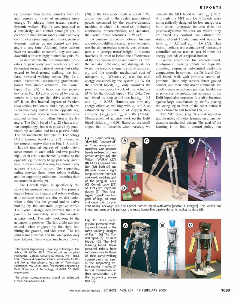
extend to level-ground walking, we built
three powered walking robots (Fig. 2) at
three institutions, substituting gravitational
power with simple actuation. The Cornell
biped (Fig. 2A) is based on the passive
device in Fig. 1D and is powered by electric
motors with springs that drive ankle push-
off. It has five internal degrees of freedom
(two ankles, two knees, and a hip), each arm
is mechanically linked to the opposite leg,
and the small body is kinematically con-
strained so that its midline bisects the hip
angle. The Delft biped (Fig. 2B) has a sim-
ilar morphology, but it is powered by pneu-
matic hip actuation and has a passive ankle.
The Massachusetts Institute of Technology
(MIT) learning biped (Fig. 2C) is based on
the simpler ramp-walkers in Fig. 1, A and B.
It has six internal degrees of freedom (two
servo motors in each ankle and two passive
hips), each arm is mechanically linked to the
opposite leg, the body hangs passively, and it
uses reinforcement learning to automatically
acquire a control policy. The supporting
online movies show these robots walking
and the supporting online text describes their
construction details (9).
The Cornell biped is specifically de-
signed for minimal energy use. The primary
energy losses for humans and robots walking
at a constant speed are due to dissipation
when a foot hits the ground and to active
braking by the actuators (negative work).
The Cornell design demonstrates that it is
possible to completely avoid this negative
actuator work. The only work done by the
actuators is positive: The left ankle actively
extends when triggered by the right foot
hitting the ground, and vice versa. The hip
joint is not powered, and the knee joints only
have latches. The average mechanical power
(10) of the two ankle joints is about 3 W,
almost identical to the scaled gravitational
power consumed by the passive-dynamic
machine on which it is based (8). Including
electronics, microcontroller, and actuators,
the Cornell biped consumes 11 W (11).
To compare efficiency between humans
and robots of different sizes, it is convenient to
use the dimensionless specific cost of trans-
port, ct0 (energy used)/(weight � distance
traveled). In order to isolate the effectiveness
of the mechanical design and controller from
the actuator efficiency, we distinguish be-
tween the specific energetic cost of transport,
cet
, and the specific mechanical cost of
transport, cmt
. Whereas cet
uses the total
energy consumed by the system (11 W for
the Cornell biped), cmt
only considers the
positive mechanical work of the actuators
(3 W for the Cornell biped). The 13-kg Cor-
nell biped walking at 0.4 m/s has cet, 0.2
and cmt
, 0.055. Humans are similarly
energy effective, walking with cet, 0.2, as
estimated by the volume of oxygen they
consume (VO2
), and cmt
, 0.05 (12–14).
Measurement of actuator work on the Delft
biped yields cmt
, 0.08. Based on the small
slopes that it descends when passive, we
estimate the MIT biped to have cmt
Q 0.02.
Although the MIT and Delft bipeds were
not specifically designed for low-energy use,
both inherit energetic features from the
passive-dynamic walkers on which they
are based. By contrast, we estimate the
state-of-the-art Honda humanoid Asimo to
have cet
, 3.2 and cmt
, 1.6 (15). Thus
Asimo, perhaps representative of joint-angle
controlled robots, uses at least 10 times the
energy (scaled) of a typical human.
Control algorithms for state-of-the-art,
level-ground walking robots are typically
complex, requiring substantial real-time
computation. In contrast, the Delft and Cor-
nell bipeds walk with primitive control al-
gorithms. Their only sensors detect ground
contact, and their only motor commands are
on/off signals issued once per step. In addition
to powering the motion, hip actuation in the
Delft biped also improves fore-aft robustness
against large disturbances by swiftly placing
the swing leg in front of the robot before it
has a chance to fall forward (16, 17).
The MIT biped (Fig. 2C) is designed to
test the utility of motor learning on a passive-
dynamic mechanical design. The goal of the
learning is to find a control policy that
1Mechanical Engineering, University of Michigan, AnnArbor, MI 48104, USA. 2Theoretical and AppliedMechanics, Cornell University, Ithaca, NY 14853,USA. 3Brain and Cognitive Sciences and Center for Bitsand Atoms, Massachusetts Institute of Technology,Cambridge, MA 02139, USA. 4Mechanical Engineering,Delft University of Technology, NL-2628 CD Delft,Netherlands.
*To whom correspondence should be addressed.E-mail: [email protected]
Fig. 1. ‘‘Ramp-walking,’’‘‘downhill,’’ ‘‘unpowered,’’or ‘‘passive-dynamic’’machines. Our poweredbipeds are based on thesepassive designs. (A) TheWilson ‘‘Walkie’’ (27).(B) MIT’s improved ver-sion (28). Both (A) and(B) walk down a slightramp with the ‘‘comical,awkward, waddling gaitof the penguin’’ (27).(C) Cornell copy (29)of McGeer’s capstonedesign (7). This four-legged ‘‘biped’’ has twopairs of legs, an innerand outer pair, to pre-vent falling sideways. (D) The Cornell passive biped with arms [photo: H. Morgan]. This walker hasknees and arms and is perhaps the most humanlike passive-dynamic walker to date (8).
B
C DA
Fig. 2. Three level-ground powered walk-ing robots based on theramp-walking designsof Fig. 1. (A) The Cor-nell biped. (B) The Delftbiped. (C) The MITlearning biped. Thesepowered robots havemotions close to thoseof their ramp-walkingcounterparts as seenin the supporting on-line movies (movies S1to S3). Information ontheir construction is inthe supporting onlinetext (9).
A B C
R E P O R T S
www.sciencemag.org SCIENCE VOL 307 18 FEBRUARY 2005 1083
stabilizes the robot_s trajectory on level terrain
using the passive ramp-walking trajectory as
the target. The robot acquires a feedback
control policy that maps sensors to actions
using a function approximator with 35 param-
eters. With every step that the robot takes, it
makes small, random changes to the parame-
ters and measures the change in walking
performance. This measurement yields a
noisy sample of the relation between the
parameters and the performance, called the
performance gradient, on each step. By means
of an actor-critic reinforcement learning al-
gorithm (18), measurements from previous
steps are combined with the measurement
from the current step to efficiently estimate
the performance gradient on the real robot
despite sensor noise, imperfect actuators, and
uncertainty in the environment. The algorithm
uses this estimate in a real-time gradient de-
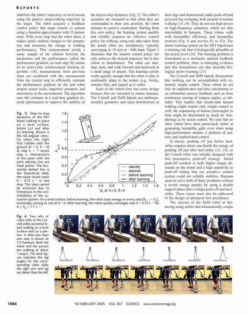
scent optimization to improve the stability of
the step-to-step dynamics (Fig. 3). The robot_sactuators are mounted so that when they are
commanded to their zero position, the robot
imitates its passive counterpart. Starting from
this zero policy, the learning system quickly
and reliably acquires an effective control
policy for walking, using only data taken from
the actual robot (no simulations), typically
converging in 10 min or È600 steps. Figure 3
illustrates that the learned control policy not
only achieves the desired trajectory but is also
robust to disturbances. The robot can start,
stop, steer, and walk forward and backward at
a small range of speeds. This learning system
works quickly enough that the robot is able to
continually adapt to the terrain (e.g., bricks,
wooden tiles, and carpet) as it walks.
Each of the robots here has some design
features that are intended to mimic humans.
The Cornell and Delft bipeds use anthropo-
morphic geometry and mass distributions in
their legs and demonstrate ankle push-off and
powered leg swinging, both present in human
walking (14, 19). They do not use high-power
or high-frequency actuation, which are also
unavailable to humans. These robots walk
with humanlike efficiency and humanlike
motions (Fig. 4 and movies S1 to S3). The
motor learning system on the MIT biped uses
a learning rule that is biologically plausible at
the neural level (20). The learning problem is
formulated as a stochastic optimal feedback
control problem; there is emerging evidence
that this formulation can also describe bio-
logical motor learning (21).
The Cornell and Delft bipeds demonstrate
that walking can be accomplished with ex-
tremely simple control. These robots do not
rely on sophisticated real-time calculations or
on substantial sensory feedback such as from
continuous sensing of torques, angles, or atti-
tudes. This implies that steady-state human
walking might require only simple control as
well; the sequencing of human joint-angles in
time might be determined as much by mor-
phology as by motor control. We note that no
other robots have done particularly better at
generating humanlike gaits even when using
high-performance motors, a plethora of sen-
sors, and sophisticated control.
In theory, pushing off just before heel-
strike requires about one-fourth the energy of
pushing off just after heel-strike (22, 23), so
the Cornell robot was initially designed with
this preemptive push-off strategy. Initial
push-off resulted in both higher torque de-
mands on the motor and a high sensitivity to
push-off timing that our primitive control
system could not reliably stabilize. Humans
seem to solve both of these problems without
a severe energy penalty by using a double
support phase that overlaps push-off and heel-
strike. These issues must also be addressed
in the design of advanced foot prostheses.
The success of the Delft robot at bal-
ancing using ankles that kinematically couple
Fig. 3. Step-to-stepdynamics of the MITbiped walking in placeon a level surface,before (q) and after(x) learning. Shown isthe roll angular veloc-ity when the rightfoot collides with theground (q 0 0, q 9 0)at step n þ 1 versusstep n. Intersectionsof the plots with thesolid identity line arefixed points. The hor-izontal dashed line isthe theoretical ideal;the robot would reachq 0 0.75 sj1 in onestep. This ideal cannotbe achieved due tolimitations in the con-trollability of the ac-tuation system. On a level surface, before learning, the robot loses energy on every step (qnþ1 G qn),eventually coming to rest at q 0 0. After learning, the robot quickly converges near q 0 0.75 sj1 for0 e q0 e 1.7 sj1.
0 10
0.2
0.4
0.6
0.8
1
1.2
1.4
1.6
n at = 0θ
θ
θ
θ
θ, > 0
n+1
identitydesiredbefore learningafter learning
0.2 0.4 0.6 0.8 1.2 1.4 1.6. .
.
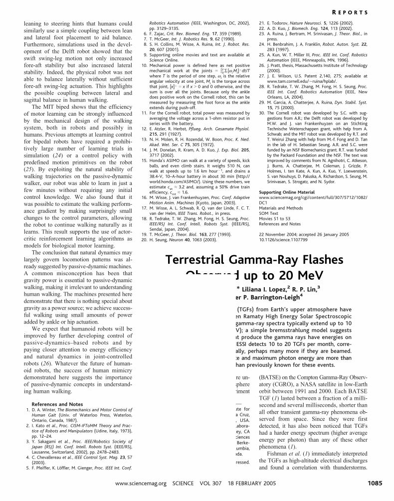
Fig. 4. Two sets ofvideo stills of the Cor-nell ankle-powered bi-ped walking on a levelsurface next to a per-son. A little less thanone step is shown at7.5 frames/s. Both therobot and the personare walking at about1 step/s. The stick fig-ure indicates the legangles for the corre-sponding video stills;the right arm and legare darker than the left.
R E P O R T S
18 FEBRUARY 2005 VOL 307 SCIENCE www.sciencemag.org1084
leaning to steering hints that humans could
similarly use a simple coupling between lean
and lateral foot placement to aid balance.
Furthermore, simulations used in the devel-
opment of the Delft robot showed that the
swift swing-leg motion not only increased
fore-aft stability but also increased lateral
stability. Indeed, the physical robot was not
able to balance laterally without sufficient
fore-aft swing-leg actuation. This highlights
the possible coupling between lateral and
sagittal balance in human walking.
The MIT biped shows that the efficiency
of motor learning can be strongly influenced
by the mechanical design of the walking
system, both in robots and possibly in
humans. Previous attempts at learning control
for bipedal robots have required a prohibi-
tively large number of learning trials in
simulation (24) or a control policy with
predefined motion primitives on the robot
(25). By exploiting the natural stability of
walking trajectories on the passive-dynamic
walker, our robot was able to learn in just a
few minutes without requiring any initial
control knowledge. We also found that it
was possible to estimate the walking perform-
ance gradient by making surprisingly small
changes to the control parameters, allowing
the robot to continue walking naturally as it
learns. This result supports the use of actor-
critic reinforcement learning algorithms as
models for biological motor learning.
The conclusion that natural dynamics may
largely govern locomotion patterns was al-
ready suggested by passive-dynamic machines.
A common misconception has been that
gravity power is essential to passive-dynamic
walking, making it irrelevant to understanding
human walking. The machines presented here
demonstrate that there is nothing special about
gravity as a power source; we achieve success-
ful walking using small amounts of power
added by ankle or hip actuation.
We expect that humanoid robots will be
improved by further developing control of
passive-dynamics–based robots and by
paying closer attention to energy efficiency
and natural dynamics in joint-controlled
robots (26). Whatever the future of human-
oid robots, the success of human mimicry
demonstrated here suggests the importance
of passive-dynamic concepts in understand-
ing human walking.
References and Notes1. D. A. Winter, The Biomechanics and Motor Control of
Human Gait (Univ. of Waterloo Press, Waterloo,Ontario, Canada, 1987).
2. I. Kato et al., Proc. CISM-IFToMM Theory and Prac-tice of Robots and Manipulators (Udine, Italy, 1973),pp. 12–24.
3. Y. Sakagami et al., Proc. IEEE/Robotics Society ofJapan (RSJ) Int. Conf. Intell. Robots Syst. (IEEE/RSJ,Lausanne, Switzerland, 2002), pp. 2478–2483.
4. C. Chevallereau et al., IEEE Control Syst. Mag. 23, 57(2003).
5. F. Pfeiffer, K. Loffler, M. Gienger, Proc. IEEE Int. Conf.
Robotics Automation (IEEE, Washington, DC, 2002),pp. 3129–3135.
6. F. Zajac, Crit. Rev. Biomed. Eng. 17, 359 (1989).7. T. McGeer, Int. J. Robotics Res. 9, 62 (1990).8. S. H. Collins, M. Wisse, A. Ruina, Int. J. Robot. Res.
20, 607 (2001).9. Supporting online movies and text are available at
Science Online.10. Mechanical power is defined here as net positive
mechanical work at the joints 0 X0T S [wi Mi]
þdt/Twhere T is the period of one step, wi is the relativeangular velocity at one joint, Mi is the torque acrossthat joint, [x]þ 0 x if x 9 0 and 0 otherwise, and thesum is over all the joints. Because only the ankledoes positive work on the Cornell robot, this can bemeasured by measuring the foot force as the ankleextends during push-off.
11. For the Cornell robot, total power was measured byaveraging the voltage across a 1-ohm resistor put inseries with the battery.
12. E. Atzler, R. Herbst, Pflueg. Arch. Gesamate Physiol.215, 291 (1927).
13. N. H. Molen, R. H. Rozendal, W. Boon, Proc. K. Ned.Akad. Wet. Ser. C 75, 305 (1972).
14. J. M. Donelan, R. Kram, A. D. Kuo, J. Exp. Biol. 205,3717 (2002).
15. Honda’s ASIMO can walk at a variety of speeds, kickballs, and even climb stairs. It weighs 510 N, canwalk at speeds up to 1.6 km hourj1, and drains a38.4-V, 10–A-hour battery in about 30 min (http://world.honda.com/ASIMO/). Using these numbers, weestimate cet , 3.2 and, assuming a 50% drive trainefficiency, cmt , 1.6.
16. M. Wisse, J. van Frankenhuyzen, Proc. Conf. AdaptiveMotion Anim. Machines (Kyoto, Japan, 2003).
17. M. Wisse, A. L. Schwab, R. Q. van der Linde, F. C. T.van der Helm, IEEE Trans. Robot., in press.
18. R. Tedrake, T. W. Zhang, M. Fong, H. S. Seung, Proc.IEEE/RSJ Int. Conf. Intell. Robots Syst. (IEEE/RSJ,Sendai, Japan, 2004).
19. T. McGeer, J. Theor. Biol. 163, 277 (1993).20. H. Seung, Neuron 40, 1063 (2003).
21. E. Todorov, Nature Neurosci. 5, 1226 (2002).22. A. D. Kuo, J. Biomech. Eng. 124, 113 (2002).23. A. Ruina, J. Bertram, M. Srinivasan, J. Theor. Biol., in
press.24. H. Benbrahim, J. A. Franklin, Robot. Auton. Syst. 22,
283 (1997).25. A. Kun, W. T. Miller III, Proc. IEEE Int. Conf. Robotics
Automation (IEEE, Minneapolis, MN, 1996).26. J. Pratt, thesis, Massachusetts Institute of Technology
(2000).27. J. E. Wilson, U.S. Patent 2,140, 275; available at
www.tam.cornell.edu/Èruina/hplab/.28. R. Tedrake, T. W. Zhang, M. Fong, H. S. Seung, Proc.
IEEE Int. Conf. Robotics Automation (IEEE, NewOrleans, LA, 2004).
29. M. Garcia, A. Chatterjee, A. Ruina, Dyn. Stabil. Syst.15, 75 (2000).
30. The Cornell robot was developed by S.C. with sug-gestions from A.R.; the Delft robot was developed byM.W. and J. van Frankenhuyzen on an StichtingTechnische Wetenschappen grant, with help from A.Schwab; and the MIT robot was developed by R.T. andT. Weirui Zhang with help from M.-f. Fong and D. Tanin the lab of H. Sebastian Seung. A.R. and S.C. werefunded by an NSF Biomechanics grant. R.T. was fundedby the Packard Foundation and the NSF. The text wasimproved by comments from N. Agnihotri, C. Atkeson,J. Burns, A. Chatterjee, M. Coleman, J. Grizzle, P.Holmes, I. ten Kate, A. Kun, A. Kuo, Y. Loewenstein,S. van Nouhuys, D. Paluska, A. Richardson, S. Seung, M.Srinivasan, S. Strogatz, and N. Sydor.
Supporting Online Materialwww.sciencemag.org/cgi/content/full/307/5712/1082/DC1Materials and MethodsSOM TextMovies S1 to S3References and Notes
22 November 2004; accepted 26 January 200510.1126/science.1107799
Terrestrial Gamma-Ray FlashesObserved up to 20 MeVDavid M. Smith,1* Liliana I. Lopez,2 R. P. Lin,3
Christopher P. Barrington-Leigh4
Terrestrial gamma-ray flashes (TGFs) from Earth’s upper atmosphere havebeen detected with the Reuven Ramaty High Energy Solar SpectroscopicImager (RHESSI) satellite. The gamma-ray spectra typically extend up to 10to 20 megaelectron volts (MeV); a simple bremsstrahlung model suggeststhat most of the electrons that produce the gamma rays have energies onthe order of 20 to 40 MeV. RHESSI detects 10 to 20 TGFs per month, corre-sponding to È50 per day globally, perhaps many more if they are beamed.Both the frequency of occurrence and maximum photon energy are more thanan order of magnitude higher than previously known for these events.
Terrestrial gamma-ray flashes (TGFs) were un-
expectedly detected from Earth_s atmosphere
by the Burst and Transient Source Experiment
(BATSE) on the Compton Gamma-Ray Observ-
atory (CGRO), a NASA satellite in low-Earth
orbit between 1991 and 2000. Each BATSE
TGF (1) lasted between a fraction of a milli-
second and several milliseconds, shorter than
all other transient gamma-ray phenomena ob-
served from space. Since they were first
detected, it has also been noticed that TGFs
had a harder energy spectrum (higher average
energy per photon) than any of these other
phenomena (1).
Fishman et al. (1) immediately interpreted
the TGFs as high-altitude electrical discharges
and found a correlation with thunderstorms.
1Physics Department and Santa Cruz Institute forParticle Physics, University of California, Santa Cruz,1156 High Street, Santa Cruz, CA 95064, USA.2Astronomy Department and Space Sciences Labora-tory, University of California, Berkeley, Berkeley, CA94720, USA. 3Physics Department and Space SciencesLaboratory, University of California, Berkeley, Berke-ley, CA 94720, USA. 4University of British Columbia,2329 West Mall Vancouver, BC V6T 1Z4 Canada.
*To whom correspondence should be addressed.E-mail: [email protected]
R E P O R T S
www.sciencemag.org SCIENCE VOL 307 18 FEBRUARY 2005 1085
Andy Ruina
Rectangle
SUPPORTING ONLINE MATERIALfor
Efficient bipedal robots based on passive-dynamic walkers
Steven H. Collins1, Andy Ruina2∗, Russ Tedrake3, Martijn Wisse4
1Mechanical Engineering, University of Michigan, Ann Arbor, MI 48104, USA2Theoretical & Applied Mechanics, Cornell University, Ithaca, NY 14853, USA
3Brain & Cognitive Sciences and Center for Bits and Atoms,Massachusetts Institute of Technology, Cambridge, MA 02139, USA
4Mechanical Engineering, Delft University of Technology, NL-2628 CD Delft, NETHERLANDS
∗Correspondence to: [email protected].
February 11, 2005
This supporting material includes
1. Materials and Methods. Details about therobots’ construction and control.
2. An analogy. A description of the parallels(in content, not in significance) between firstpowered flight and these robots.
In addition we hope readers will look at the videos:
S1 Cornell powered biped. This movie showsvideos of the robot walking on flat ground. Aslow-motion segment shows the ankle push-off actuation.
S2 Delft pneumatic biped. This movie shows therobot walking down a hall with views from thefront, side, and back.
S3 MIT learning biped. This movie begins withthe powered robot imitating passive walkingdown a 0.9 degree slope, from three cameraangles. Then it shows the robot learning towalk on flat terrain with foam protective pads.
The controller kicks the robot into random ini-tial conditions between learning trials. Aftera few minutes, the robot is walking well inplace, so we command it to walk in a circle.Finally, we show the robot walking down thehall, on tiles and outside; this footage is takenfrom a single trial where the robot adapted toeach change in the terrain as it walked.
More material and other videos are availablethroughhttp://tam.cornell.edu/˜ruina/powerwalk.html .
1 Materials and Methods
Details about the three robots are presented here.
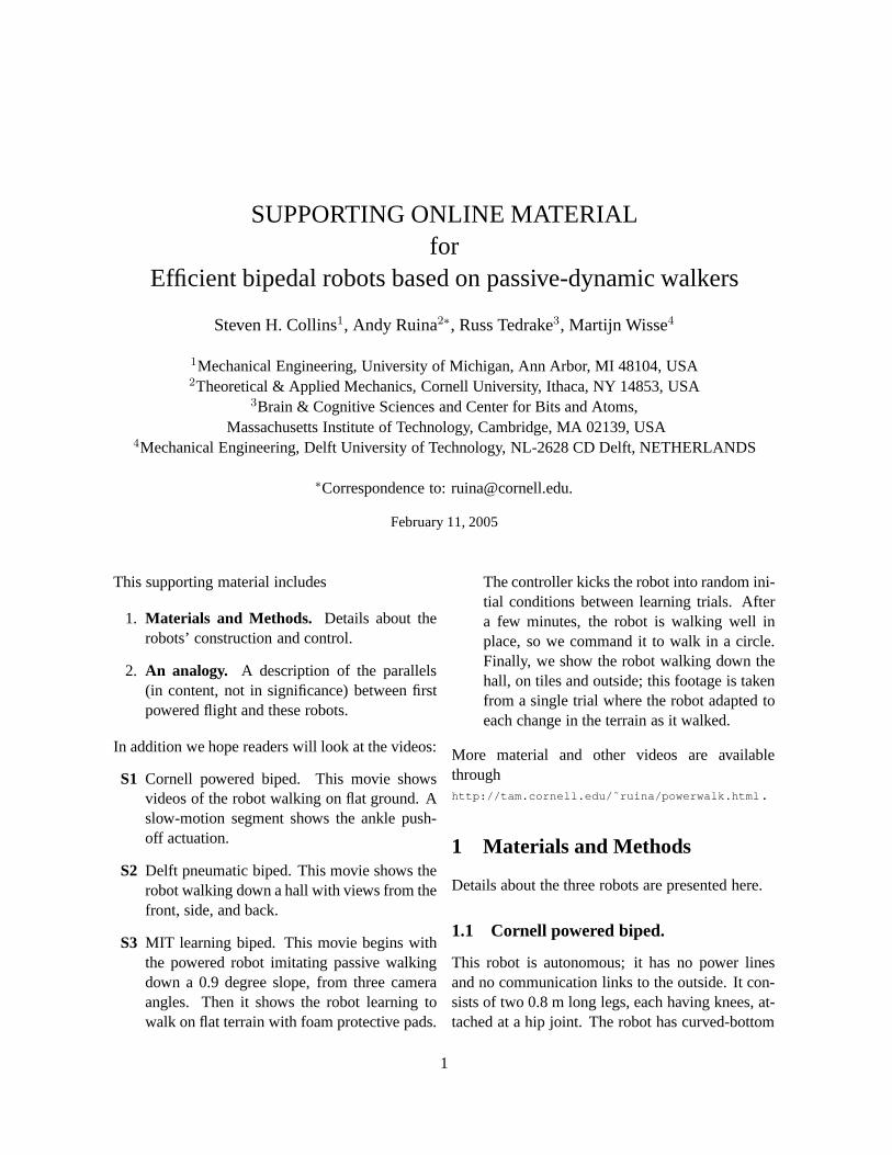
1.1 Cornell powered biped.
This robot is autonomous; it has no power linesand no communication links to the outside. It con-sists of two 0.8 m long legs, each having knees, at-tached at a hip joint. The robot has curved-bottom
1
Figure 1: The Cornell powered biped
feet, arms, and a small torso which is kept uprightby connection to the legs with an angle-bisectingmechanism. Each arm carries a battery. The rightarm is rigidly attached to the left leg andvice versa,reducing yaw oscillations (Fallis, 1888, Collins,Wisse and Ruina 2001). The machine weighs 12.7kg and has 5 internal degrees of freedom (one hip,two knees, and two ankles). The thigh-to-shanklength and mass ratios are 0.91 to 1 and 3.3 to1, respectively, which mimics human architectureand seems important to the passive dynamics of thesystem. The hip joint is fully passive. A latch ateach knee passively locks the shank to be paral-lel with its proximal thigh throughout stance. This
latch is released by a solenoid at the completion ofankle push-off, at which point the knee is passiveuntil knee-strike. Ankle push-off restores energylost, mostly to heel-strike collisions. To minimizethe needed motor size, energy for ankle push-off isstored in a spring between steps.
The control circuitry is located in thehip/torso/head visible in the figure. A finite-state machine with eight binary inputs and outputsis implemented in 68 lines of code on an AtmelAT90S8515 chip running on an ATSTK500standard development board. A second boardwith relays and passive conditioning componentsconnects the board to the electromechanical andsensory parts. During the first state, Left LegSwing, all actuators are unpowered and the leftknee latch passively locks at knee strike. Whenground-detection contact switches below theleft foot detect impending heel strike, the statechanges to Right Ankle Push-Off. This beginsa timed activation of the solenoids that releasethe plantar-flexor spring of the right foot. Whenswitches detect full foot extension, the statechanges to Right Toe Return. During this state, a9.5 Watt, 6.4 oz gear-reduced MicroMo©R motor isactivated, slowly retracting the foot and restoringspring energy. Also, a short time after detection ofimpending left-foot heel-strike, a solenoid unlocksthe right knee. When a switch on the motorindicates full foot retraction, the state changes toRight Leg Swing, and the foot-retraction motoris deactivated. The state machine then swapsroles for the left and right legs and goes to theinitial state. Taking all sensing, including thesensing of internal degrees of freedom (whichcould in principle be made open loop), about 20bits of information per step flows to the processor.Environmental sensing, i.e., the instant of footcontact, is about seven bits per step.
This machine has only one capability, walkingforward. It is designed to walk with minimal en-ergy use. Its speed, path and joint motions are notshaped or controlled but follow from its mechanicaldesign and primitive ankle push-off actuation. An-
2
kle extension occurs mostly after the opposite leghas completed heel-strike collision, so in principlethe machine could be made to consume about fourtimes less energy by having ankle push-off before,rather than after, the opposing leg’s foot-to-groundcollision (Kuo, 2002). However, push-off beforeheel-strike seems to require more precise timingand also requires greater ankle torques. We sur-rendered this possible gain in energy effectivenessin trade for greater simplicity of control.
Low energy use was a primary goal in the designof the Cornell robot. We measured its power con-sumption during walking trials using an off-boarddigital oscilloscope connected with fine wires. At500 samples per second, the scope measured bat-tery voltage on one channel, and the voltage dropacross a 1 ohm power resistor in series with thebatteries on another. The product of the voltageand current was, on average, 11 watts (yieldingcet = 0.2). Mechanical energy use was measuredin experimentally simulated push-off trials. Theforce at each foot contact point was measured asthe ankle was slowly moved through its extensionrange, and this force was integrated to estimate me-chanical work per step, yielding an average over acycle of about 3 watts (cmt = 0.055). This is aslight over-estimate of the mechanical energy usedfor propulsion because some energy is lost at thecollision between the ankle and shank at full ankleextension.
The theoretical lower limit for the cost of trans-port in walking models iscmt = 0. This can beachieved by swaying the upper body with springsin such a manner as to totally eliminate the colli-sional losses (Gomes and Ruina, 2005). Withoutswaying the upper body, a motion that would havesignificant energetic cost in humans, a rough lowerbound on energetic cost can be estimated from thepoint-mass small-angle model of Ruina, Srinivasanand Bertram (2005) as
cet ≥ cmt ≥ J(d − df )2
ℓ2
v2
2gd≈ 0.0003
whereJ is the collision reduction factor, which
is 1/4 for push-off before heel-strike,d ≈ 0.4mis the step length,df ≈ 0.2m is the foot length,ℓ ≈ 0.8m is the leg length,v = 0.4m/s is theaverage velocity, andg ≈ 10 m/s2 is the grav-ity constant. In a dynamic 3-D model (adaptedfrom Kuo 1999) with geometry, mass distribution,speed, and step length similar to this robot, with-out a hip spring or pre-emptive push-off, we foundthe mechanical cost of transport to be 0.013. Usingthe liberal collision reduction factor of 1/4 above,this yields a theoretical minimum of 0.003. Springactuated leg swing, used by humans, could alsosignificantly reduce the mechanical work require-ments for walking at this speed by reducing steplength. Thus, by a variety of estimates, the me-chanical work of this robot walking at this speed,small as it is, seems to have room for an order ofmagnitude reduction.
The Cornell powered biped walked successfullyduring a period of a few weeks starting in July2003. This robot is a proof-of-concept prototype,not a production-run machine. It was developed asa one-shot attempt using a small ($10K) budget. Asis not unusual for experimental robots, the devicedid not stand up well to long periods of testing; onaverage about one mechanical component wouldbreak per day of testing. For instance, the cablesconnecting the motor to the primary ankle exten-sion spring ran over a small radius pulley at theknee and broke frequently. When the Cornell robotwas best tuned it would walk successfully at about30% of attempts. Failed launches were due to inad-equate matching of proper initial conditions, mostoften ending with foot scuff of the swing leg. Therobot seems mildly unstable in heading, so once itwas launched, the primary failure mode was walk-ing off of the (narrow) walking table or walkinginto a wall. Uneven ground also lead to falls. Be-cause it walked 10 or more steps many times, withthe end only coming from hitting a wall or cliff, thegait is clearly stable (although not very) for bothlateral and sagital balance. However, the reader canmake his/her own judgments based on the videoswhich are the basic documentation of success.
3
A key aspect of the success, and also the touchi-ness, of this robot is the shape and construction ofthe feet. The general issues related to feet for thisclass of robots is discussed in Collins, Wisse andRuina (2001). We tried various support-rail curveshapes and overall foot stiffnesses, and only one ofthese led to successful walking.
The Cornell machine, which uses wide support-ing feet for lateral stability, is not being maintained.Rather, present efforts are aimed at developing amachine which uses simple active control for lat-eral balance using foot placement. This is usedby humans during walking (Bauby and Kuo 2000)and the idea is related to the kinematic lean-to-steermechanism of the Delft Biped and the steering usedby a bicycle rider for balance.
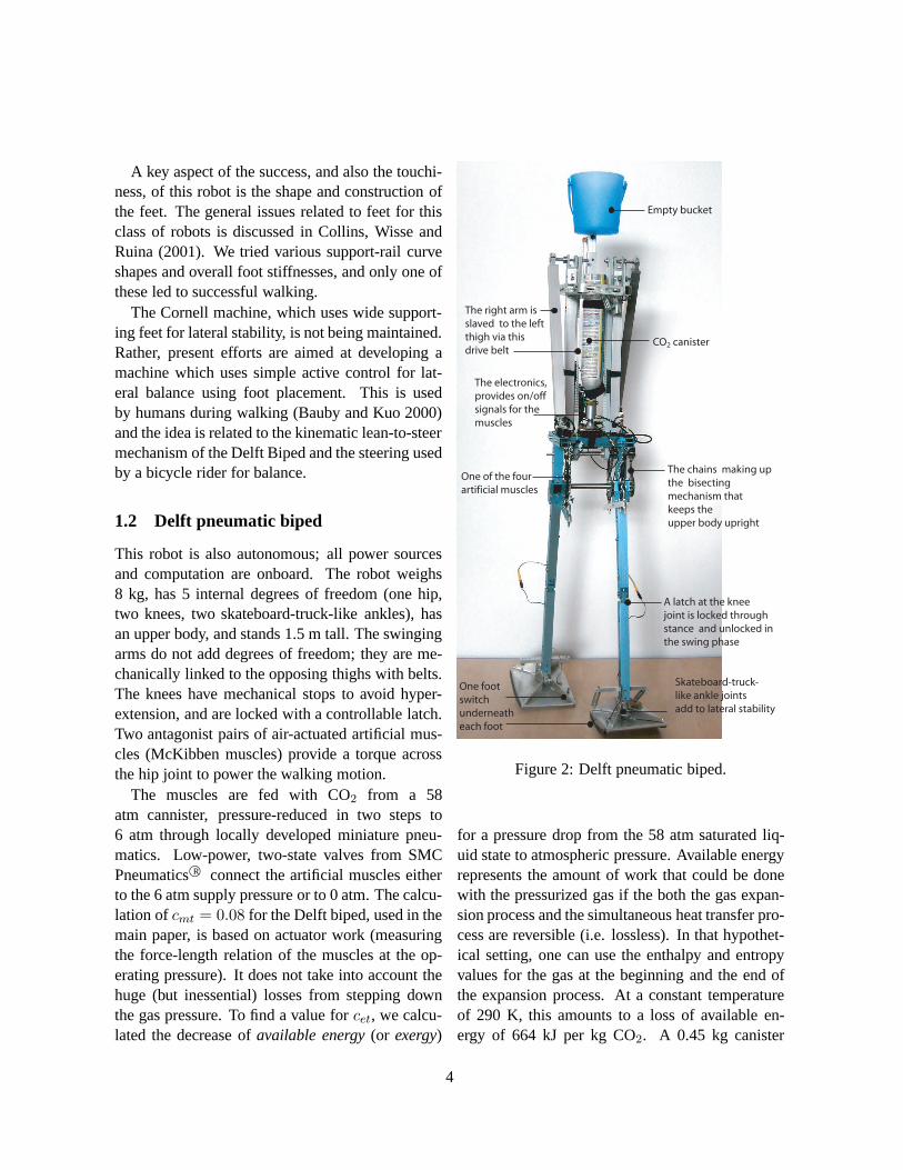
1.2 Delft pneumatic biped
This robot is also autonomous; all power sourcesand computation are onboard. The robot weighs8 kg, has 5 internal degrees of freedom (one hip,two knees, two skateboard-truck-like ankles), hasan upper body, and stands 1.5 m tall. The swingingarms do not add degrees of freedom; they are me-chanically linked to the opposing thighs with belts.The knees have mechanical stops to avoid hyper-extension, and are locked with a controllable latch.Two antagonist pairs of air-actuated artificial mus-cles (McKibben muscles) provide a torque acrossthe hip joint to power the walking motion.
The muscles are fed with CO2 from a 58atm cannister, pressure-reduced in two steps to6 atm through locally developed miniature pneu-matics. Low-power, two-state valves from SMCPneumatics©R connect the artificial muscles eitherto the 6 atm supply pressure or to 0 atm. The calcu-lation ofcmt = 0.08 for the Delft biped, used in themain paper, is based on actuator work (measuringthe force-length relation of the muscles at the op-erating pressure). It does not take into account thehuge (but inessential) losses from stepping downthe gas pressure. To find a value forcet, we calcu-lated the decrease ofavailable energy(or exergy)
A latch at the knee
joint is locked through
stance and unlocked in
the swing phase
The right arm is
slaved to the left
thigh via this
drive belt
The chains making up
the bisecting
mechanism that
keeps the
upper body upright
CO2 canister
The electronics,
provides on/off
signals for the
muscles
One foot
switch
underneath
each foot
One of the four
artificial muscles
Empty bucket
Skateboard-truck-
like ankle joints
add to lateral stability
Figure 2: Delft pneumatic biped.
for a pressure drop from the 58 atm saturated liq-uid state to atmospheric pressure. Available energyrepresents the amount of work that could be donewith the pressurized gas if the both the gas expan-sion process and the simultaneous heat transfer pro-cess are reversible (i.e. lossless). In that hypothet-ical setting, one can use the enthalpy and entropyvalues for the gas at the beginning and the end ofthe expansion process. At a constant temperatureof 290 K, this amounts to a loss of available en-ergy of 664 kJ per kg CO2. A 0.45 kg canister
4

can power the 8 kg robot for 30 min of walkingat 0.4 m/s yieldingcet = 5.3. This value has lit-tle meaning, however. First, even the best real-world gas-expansion systems can only use about30% of the theoretically available energy, due toirreversibility issues. More importantly, most ofthe expansion loss would be eliminated if the CO2
had been stored at 6 atm. Unfortunately this wouldrequire an impractically large storage tank. Thusthe discrepancy betweencet = 5.3 andcmt = 0.08is due to practical problems associated with usingcompressed-gas energy storage.
McKibben muscles have a low stiffness whenunactuated, leaving the joints to behave almost pas-sively at zero pressure. At higher pressures, theMcKibben muscles behave as progressively stiffersprings. By activating opposing muscles in differ-ent proportions, the relaxed angle of a joint can becontrolled. This is applied at the hip where the ar-tificial muscles alternate in action. At the start ofeach step, determined by a foot switch, one mus-cle is set to 6 atm and the other to 0 atm. Theswing leg is thus accelerated forward until the re-laxed angle of the hip is reached, where it (approxi-mately) stays due to damping in the muscles and inthe joint. If sufficient hip joint stiffness is obtainedfrom the hip muscles, stable walking similar to thatof McGeer’s four-legged machine can be obtained.The upper body is kept upright via a kinematic re-striction, a chain mechanism at the hip which con-fines the upper body to the bisection angle of thetwo legs (Wisse, Hobbelen and Schwab, 2005).
Lateral stability in two-legged robots can be ob-tained in a number of ways (Kuo, 1999), and onesolution was tested in the Delft robot. The feet areattached to the lower leg via special ankle joints(Wisse and Schwab, 2005) which have a joint axisthat runs from above the heel down through themiddle of the foot, quite unlike the human anklebut much like skateboard trucks. The mechanismcreates a nonholonomic constraint, which can en-able stability without dissipation, as found in skate-boards (Hubbard, 1979). If the robot starts to lean
sideways as a result of a disturbance, the ankle al-lows the foot to remain flat on the floor. Due tothe tilted joint orientation, the leaning is accompa-nied by steering. If the walker has sufficient for-ward velocity, this steering helps prevent it fromfalling sideways, much like the turning of a bikewheel into a fall helps prevent a bike from fallingdown.
A Universal Processor Board from MultiMotions©R (based on the Microchip©R PIC16F877micro-controller) uses foot-contact switch signalsto open or close the pneumatic valves. The controlprogram is a state machine with two states: eitherthe left or the right leg is in swing phase. At thebeginning of the swing phase, the swing knee isbent. Four hundred milliseconds after the start ofthe swing phase, the knee latch is closed, waitingfor the lower leg to reach full extension through itspassive swing motion. Programmed in assembly,this amounts to about 30 lines of code. The onlysensing is the time of foot contact, used once perstep. Taking account of the implicit rounding fromthe processor loop time, we estimate the sensor in-formation flow rate is about six bits per second.
The Delft powered biped first walked success-fully in July 2004. When mechanically sound, mostof the manual launches (by an experienced person)result in a steady walk. Falls can often be attributedto disturbances from within the machine (a contactswitch that performs unreliably, or a cable that getsstuck between parts), and occasionally to floor ir-regularities. Another problem is that the pneumaticand mechanical systems (which were developed atDelft for a proof-of-principle prototype rather thanan industrial-strength product) have frequent me-chanical failures that often need a day or more tofix. At present the machine is being kept workingso it can repeat the behavior shown in movie S2.
1.3 MIT learning biped.
First we duplicated the Wilson design (Fig. 1a ofthe main paper) using two rigid bodies connectedby a simple hinge. The kneeless morphology was
5
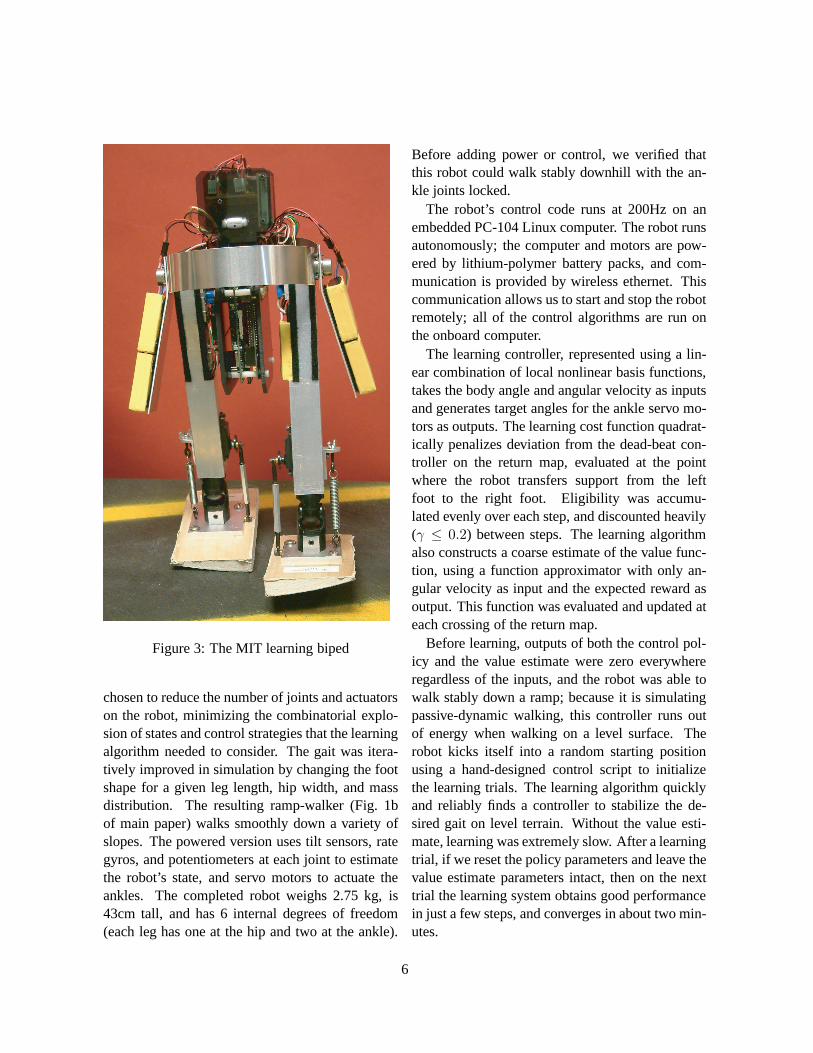
Figure 3: The MIT learning biped
chosen to reduce the number of joints and actuatorson the robot, minimizing the combinatorial explo-sion of states and control strategies that the learningalgorithm needed to consider. The gait was itera-tively improved in simulation by changing the footshape for a given leg length, hip width, and massdistribution. The resulting ramp-walker (Fig. 1bof main paper) walks smoothly down a variety ofslopes. The powered version uses tilt sensors, rategyros, and potentiometers at each joint to estimatethe robot’s state, and servo motors to actuate theankles. The completed robot weighs 2.75 kg, is43cm tall, and has 6 internal degrees of freedom(each leg has one at the hip and two at the ankle).
Before adding power or control, we verified thatthis robot could walk stably downhill with the an-kle joints locked.
The robot’s control code runs at 200Hz on anembedded PC-104 Linux computer. The robot runsautonomously; the computer and motors are pow-ered by lithium-polymer battery packs, and com-munication is provided by wireless ethernet. Thiscommunication allows us to start and stop the robotremotely; all of the control algorithms are run onthe onboard computer.
The learning controller, represented using a lin-ear combination of local nonlinear basis functions,takes the body angle and angular velocity as inputsand generates target angles for the ankle servo mo-tors as outputs. The learning cost function quadrat-ically penalizes deviation from the dead-beat con-troller on the return map, evaluated at the pointwhere the robot transfers support from the leftfoot to the right foot. Eligibility was accumu-lated evenly over each step, and discounted heavily(γ ≤ 0.2) between steps. The learning algorithmalso constructs a coarse estimate of the value func-tion, using a function approximator with only an-gular velocity as input and the expected reward asoutput. This function was evaluated and updated ateach crossing of the return map.
Before learning, outputs of both the control pol-icy and the value estimate were zero everywhereregardless of the inputs, and the robot was able towalk stably down a ramp; because it is simulatingpassive-dynamic walking, this controller runs outof energy when walking on a level surface. Therobot kicks itself into a random starting positionusing a hand-designed control script to initializethe learning trials. The learning algorithm quicklyand reliably finds a controller to stabilize the de-sired gait on level terrain. Without the value esti-mate, learning was extremely slow. After a learningtrial, if we reset the policy parameters and leave thevalue estimate parameters intact, then on the nexttrial the learning system obtains good performancein just a few steps, and converges in about two min-utes.
6
The resulting controller outputs ankle com-mands that are a simple, time-independent functionof the state of the robot, and does not require anydynamic models. All learning trials were carriedout on the physical biped with no offline simula-tions. The learned controller is quantifiably (usingthe eigenvalues of the return map) more stable thanany controller we were able to design by hand, andrecovers from most perturbations in as little as onestep. The robot continually learns and adapts to theterrain as it walks.
The MIT biped, which was not optimized for en-ergy efficiency, hascet = 10.5, as calculated by theenergy put back into the batteries by the rechargerafter 30 minutes of walking. Thecet for this robotis especially high because the robot has a powerfulcomputer (700 MHz Pentium) on a light robot thatwalks slowly.
The version of the MIT powered biped shownhere first walked successfully in January 2004. Theearliest powered prototype of this type at MIT firstwalked successfully in June 2003.
The MIT biped is still working well, and is thesubject of active development and study. Newlearning algorithms and new design elements (suchas different curvatures in the feet) are being testedwith the same hardware. A new version with kneesis mostly developed. The robot has walked fora few one-hour on-the-treadmill energy-use trials(the batteries would have lasted for about 90-100minutes).
2 Analogy with first poweredflight*
On December 17, 1903 the Wright brothers firstflew a heavier-than-air man-carrying powered ma-chine. There are various parallels between theirmachine and the simply-powered low-energy-usewalking robots described here.
Starting from before the work began, theWright’s were inspired by flying toys. The walk-ing machines here were also inspired by, and even
partially based on, walking toys.The Wright’s ideas about control of steer in air-
craft were based on the relation between steer andlean in bicycles. Our research in the passive bal-ance of robots was inspired by the self-stability ofbicycles.
The Wrights worked for years developing glid-ers, planes powered by the release of gravitationalpotential energy as they flew down a glide slope.This was in contradiction to a common paradigmof the time, which was to try to get a powered planeto work, motor and all, all at once. Once they hadmastered gliding they were confident they couldmaster powered flight. On the second day they triedthe idea, adding a primitive engine to a glider de-sign, they made their famous flight. Our develop-ment of passive-dynamic walkers, robots that walkdown gentle slopes powered only by gravity, wasby far the bulk of our efforts. Once we had thoseworking well we were confident that the machinescould walk on the level with a small addition ofpower. The result that adding power to a downhillmachine works is one of the subjects of this paper.
The analogy above is not accidental. TadMcGeer, the pioneer of passive-dynamic robotics,was trained as an aeronautical engineer. McGeer’sforay into robotics was directly and explicitly animitation of the Wright Brothers paradigm. Itworked for the Wrights after others failed at mas-tering power and flight all at once. Perhaps,McGeer thought, it could work for the more pedes-trian task of making an efficient walking robot.McGeer put aside the project after making signifi-cant progress with passive machines (walking robotgliders), returning to the world of airplane design.Our research has been, more or less, to pick upwhere McGeer left off, improve the ‘gliders’, andthen add simple power.
* The analogy has its limits. Heavier-than-airpowered flight was a well-defined major goal over along period of time with huge consequences. That
7

accomplishment swamps anything that might hap-pen with robotics, including this research. TheWright analogy does not extend to the significanceof our work, which is hugely less.
References for supplementary mate-rial
C. E. Bauby, A. D. Kuo,J. Biomech. 33, 1433(2000).
S. H. Collins, M. Wisse, A. Ruina,Int. J. Robot.Res.20, 607 (2001).
G. T. Fallis, Walking toy, Patent, U.S.Patent Office (1888). Available athttp://www.tam.cornell.edu/.ruina/hplab.
M. Gomes, and A. Ruina,Phys. Rev. Letters Einpress (2005).
M. Hubbard,J. Appl. Mech.46, 931 (1979).
A. D. Kuo, J. Biomech. Eng.124, 113 (2002).
A. D. Kuo, Int. J. Robot. Res.18, 917 (1999).
A. Ruina, M. Srinivasan, and J. Bertram, J. Theor.Biol. in press (2005).
M. Wisse, A.L. Schwab,Int. J. Robot. Res., inpress (2005)
M. Wisse, D.G.E. Hobbelen, A.L. Schwab,IEEET. Robot., in press (2005)
8
Related Documents