ADDIS ABABA UNIVERSITY SCHOOL OF GRADUATE STUDIES EFFICIENCY OF GAS FILLED DETECTOR FOR BETA AND GAMMA RADIATIONS By ANNO KARE ANNO July 2006 Addis Ababa

Welcome message from author
This document is posted to help you gain knowledge. Please leave a comment to let me know what you think about it! Share it to your friends and learn new things together.
Transcript
ADDIS ABABA UNIVERSITY
SCHOOL OF GRADUATE STUDIES
EFFICIENCY OF GAS FILLED DETECTOR
FOR BETA AND GAMMA RADIATIONS
By
ANNO KARE ANNO
July 2006
Addis Ababa
EFFICIENCY OF GAS FILLED
DETECTOR FOR
THE DETECTION OF BETA AND GAMMA RADIATIONS
A PROJECT PRESENTED TO THE SCHOOLOF GRADUATE STUDIESOF
ADDIS ABABA UNIVERSITY
IN PARTIAL FULFILMENT OF THE REQUIREMENTS FOR MASTER OF SCIENCE IN PHYSICS
BY ANNO KARE ANNO
July 2006 Addis Ababa
ADDIS ABABA UNIVERSITY
SCHOOL OF GRADUATE SUDIES
Efficiency of Gas Filled Detector For
The detection of Beta and Gamma Radiations
By Anno Kare
Approved by the Board of Examiners
------------------------------------ --------------------------- Chairman, Department Graduate Committee Signature ------------------------------------------- --------------------------------- Advisor Signature -------------------------------------------- ---------------------------------
Examiner Signature
Abstract There are many forms of radiation –heat, light, radar, radio waves etc. differ from
one another in frequency but not in kind. The so called “kinds” of radiation are
characterized by the techniques used to produce and detect them; The classical theory of
Maxwell applies to all these radiations and all are ultimately due to the acceleration of
electrical charges. Except for differences of frequency, and observation made on
one’Kind “of radiation must also be true of all other kinds.
Radiation is energy in the form of waves or particles. The great majority of it
occurs naturally and we are all exposed to it all of the time .It is all around us-in
atmosphere, the earth, our food our bodies and from cosmic rays, from outer space and
medical X-rays. Radiation can be produced from a variety of sources. There are two
broad types - ionizing and non-ionizing radiation - classified in terms of their effects on
matter. Non-ionizing radiation includes some ultra violet light, visible and infrared light,
microwaves, radar and radio waves. Ionizing radiation is that which has enough energy to
remove an electron from an atom, thereby producing an ion - an electrically charged atom
or grouping of atoms. Cosmic rays, x-rays and the radiation emitted by the decay of
radioactive substances are examples of ionizing radiation. Although they are types of
radiation, alpha and beta particles and neutrons are not parts of the electro-magnetic
spectrum because they are particles not waves. We are most affected by ionizing
radiation, which deposits some of its energy as a result of electrical interactions when it
passes through matter. It can be harmful to the human body in excessive doses because it
can damage individual cells, possibly resulting in damage to organs, or other long-term
effects.
Radiologist discovered that repeated exposure of their hands to X-rays resulted in skin
burns. This discovery led to the wide spread use of X-rays in the treatment of cancer.
Also it was realized that excessive exposure of the body to radiation could result in
radiation different in their biological effect on tissues even when the absorbed dose is the
same. This basically depends on ionizing power of radiation. The relative biological
effectiveness of electrons and positions are the same. Whereas, heavy ionizing particles
such as alpha particles and fission fragments produce much greeter biological effect.
However, containing it, shielding against it, moving away from it, or removing the source
can gain effective protection from radiation. Radiation has the same effect, whether from
natural or man-made sources. Most people receive their greatest exposure to radiation
from the naturally occurring radioactive gas radon. It is produced as a result of the decay
of uranium - which is present in all rocks and soils. We all breathe it every day and it
accounts for about 50 per cent of our total radiation dose. In fact, about 85 per cent of our
total dose is the result of naturally occurring radiation. Medical sources, such as x-rays,
account for a further 14 per cent. The fall-out from past nuclear weapons tests and
incidents such as Chernobyl amount to 0.2 per cent and discharges from the nuclear
industry total much less than 0.1 per cent
It may be wondered why it is, if the surfaces of all bodies are continually emitting
radiant energy, that all bodies do not eventually radiate away all their internal energy and
cool down to a temperature of absolute zero. The answer is that they would do so if
energy were not supplied to them in some way. In the case of filament of an eclectic
lamp, energy is supplied electrically to make up for the energy radiated. As soon as the
energy supply is cut off, bodies do, infact, cool down very quickly to room temperature.
The reason that they don not cool further is that their surroundings (the walls, and other
objects in the room) are also radiating and some of this radiant energy is intercepted,
absorbed and converted into internal energy. The same thing is true of all other objects in
the room –each is both emitting and absorbing radiant energy simultaneously.

ACKNOWLEGEMENT
I would like to express my appreciation and Heart felt gratitude to
professor A.K. Chaubey, my project Advisor for his invaluable
professional advice by giving me intellectual guidance, unreserved
suggestions and constructive comments. With out his great dedication
and assistance, the completion of this work has been impossible.
My special thanks also goes to my wife Chaltu Alemayehu and my
children Tigist Anno, Amanuel Anno and Ebise Anno whose eagerness to
see my success and their unreserved support were engines to my
educational endeavors. I also appreciate their patience & long endurance
specially during my last semester times.
I would like also to acknowledge and say congratulations to all family
members, who are at the back of all my work & eagerly waiting for my
success my father Ato Kare Anno, my mother W/o Guye Mamo, Ato Liyo
Gebre Micael & Ato wolde Gebre Micael and also my brothers & sisters.
Above all, I thank the almighty God who helped me in every aspect from
the beginning to the end of my study years. Passing through
unforgettable bad incident in August 1992 and also obstacles from the
beginning till the end of my studies coming to this even is a great victory.
My almighty Heavenly father, who told me to join this programme &
accomplished accordingly due the glory. If God were not with me I could
not have accomplished the work.
More over my thanks also goes to Oromiya education Bureau east
wollega education Bureau, Nekemte Town Woreda Education Bureau for
their cooperation & financial support till the end my study years.
Finally, I would like to acknowledge, all the department members of
physics (AAU) and specially my graduate instructor for their cooperation
and instance for their cooperation and instance throughout my study
years .I well like also to express my indebted to all my fiends who helped
me directly or indirectly, who assisted me is many ways special Zewdie
meko Cherinet Amente & Kumesa Gelana during my stay in graduate
school.
INTRODUCTION
Nuclear Physics deals with the structure, properties & transformation of
atomic nucleus. It is one of the most modern branches of science. Even
at the end of 19 th century, the atomic nucleus had not been discovered
and the atom was considered to be the smallest indivisible particle of
matter. The discovery of cathode rays and x-rays in 1895 and natural
radioactivity in 1896 showed that the atomic structure of all elements
has something in common. They all contain electrons, which are emitted
under certain conditions and the heaviest elements exhibit the properties
of alpha, beta and gamma radioactivities.
The main objective of this work is primarily to study the radiations from
radioactive nucleus and in particular to determine the efficiency of has
detectors. The most impressing result of this project is its agreement
with the expected result. The fact that detection efficiency of GM counter
for beta-radiation is 88% and for gamma radiation 2% is a great
achievement.
The whole work of the project can be seen from two angles. First I have
tried to assess the theoretical background for the experiment as a
literature survey and the second part is experimental part from the start
to the end of the efficiency determination process.
The first chapter deals with atomic nucleus. Here the basic properties of
atomic nucleus its size and shape, binding energy and nuclear stability
are considered. In the second chapter I have touched the general case of
radioactivity and then inclined to nuclear radiations. In this chapter the
radioactive decay law, the three common types of nuclear radiations.
(Alpha beta and gamma) are given. In here I have discussed source of
the common types of radiation & decay schemes and have tried to focus
on the energy relation of these radiations, which is a key to understand
the internal structure of the nucleus.
The third chapter is devoted to interaction of charged radiations and
uncharged radiations in general and then focuses on beta-radiation &
gamma radiation interactions in particular. In this chapter the four types
of electron interaction with mater and the three common cases gamma
interaction with matter are given. This is necessary as a part of this work
because the origin and hence the nature of their interaction enable us to
detect radiation.
The fourth chapter contains detectors. First the over view of detectors as
a whole and then Gas filled detectors are given. Under this the commonly
used detectors-Sodium Iodide (NaI), solid state detector-highly pure
germanium (HPGe), and then gas filled detectors are given. General
properties of gas filled detectors, ionization chambers, proportional
counters and GM counters are discussed. Specially in the last part of
this chapter basic features of GM counter, avalanche formation and
detection efficiency are included.
In all cases I have tried to touch the related concepts without deviating
from the main objective of the project as much as possible.
In the last chapter the details of the experiment are given, starting from
the experimental set up to the determination of the efficiency of GM
counter, the whole process is given. Then there are also result and
discussion comments on the obtained result. Finally, with brief
conclusion are recommendation & the whole work- completed.
1
Table of Contents
page
Abstract -------------------------------------------------------------------- i
Acknowledgement ----------------------------------------------------------iii
Introduction ----------------------------------------------------------------------1
Chapter One The Atomic Nucleus
1.1 Introduction ---------------------------------------------------------------------3
1.2 Nuclear Size & Shapes ---------------------------------------------------3
1.3 Nuclear Binding Energy -------------------------------------------------- 4
1.4 Nuclear Stability -------------------------------------------------- 6
Chapter Two Radioactivity
2.1 Discovery of Radioactivity -------------------------------------------------- 8
2.2 General Properties of Radioactivity ----------------------------------------- 9
2.3 Radioactive Decay Law -------------------------------------------------- 9
2.4 Nuclear Radiations -----------------------------------------------------------12
2.4.1 Alpha Radiation -----------------------------------------------------------12
2.4.2 Beta Radiation ---------------------------------------------------------------------16
2.4.3 Gamma Radiation ------------------------------------------------------------21
Chapter Three
Interaction of Nuclear Radiation with Matter
3.1 Introduction --------------------------------------------------------------------33
3.2 Interaction of Heavy charged Particles with matter -------------------------35
3.3 Interaction of Light charged particles with matter --------------------------39
3.4 Interaction of Gamma rays with matter ---------------------------------44
2
Chapter Four
Nuclear Radiation Detection and Measurement
4.1 Introduction ……………………………………………………………… 52
4.2 Detector Overview ……………………………………………………. 54
4.3 Gas filled Detectors …………………………………………………….. 58
Chapter Five
The Experimental Measurement of Efficiency of
Gas Filled Detector for Beta and Gamma Radiation
5.1 The Experiment..……………………………………………………….. 74
5.2 Experimental set up……………………………………………………… 74
5.3 Experimental Techniques…………………………………………………74.
5.4 The Plateau characteristic of GM counter……………………………… 75
5.5 Determination of Efficiency of Gas Filled Detector …………………… 76
5.6 Results and Discussion……………………………………………………80
5.7 Conclusion…………………………………………………………………84
References
3
Chapter One
The Atomic Nucleus
2.1 Introduction
A very different atomic model was indicated by experiments performed by Rutherford
and his associates in1911(H. Geiger and E. Marsden ).According to Rutherford gold
foil experiment, many of the alpha particles did go straight through the foil (deflected
only by very small amounts ) and amazingly some alpha particles were deflected
through very large angles .A few even returned to the side of the gold foil from which
they came .Rutherford ,s astonishment at this is evident in his comment ,”It was quite
the most incredible event that has ever happened to me in my life .It was almost as
incredible as if you fired 15 –inch shell at a piece of tissue paper and it came back and
hit you “ .
For smaller separation, (less than 10-14 m) the prediction of coulombs is not obeyed
because the nucleus no longer appears as a point charge to the alpha particle.
Rutherford concluded that (1) the positive massive part of atom was concentrated in a
very small volume at the center of the atom called nucleus, surrounded by a cloud of
electrons. (2) Because the atom is mostly empty space, many of the alpha particles go
through the foil with practically no deviation. But an alpha particle passes closer to the
nucleus experiences a very large force exerted by a massive positive core and is
deflected through large angles in a single encounter.
From alpha decay studies it was known that heavy nuclei can, to some extent, break
up in to smaller and identical constituents. Clearly, it is therefore built up of more
elementary particles. However, it was known before 1932 exactly what these particles
were. In that year Chad wick discovered the neutron, and since that discovery, it has
been generally accepted that the nucleus is built up of neutrons and protons. In beta
and induced reactions at high energies, other particles may emerge from the nucleus.
However, we now believe that these particles are created in the nucleus at the moment
of emission and are therefore not to be considered as constituents of the nucleus.[7]
4
2.2 Nuclear Sizes and Shapes
Atoms of each element contain a number of protons in the nucleus equal to the atomic
number, and a like number of orbital electrons. In addition, all nuclei of all atoms
except hydrogen contain one or more neutrons. Since like electric charges repel each
other, each proton is repelled by all other protons in the nucleus. As the number of
protons increases, the magnitude of the force on any one proton increases becoming so
large that all nuclei with more than 83 protons are radioactive. No nucleus with more
than one proton can exist without neutrons. Neutrons are essential in such nuclei to
bind together the positively charged protons.[4]
........ What is the nature of the force of attraction holding the nuclear properties
together? The gravitational force is negligible, and the electric forces tend to disrupt
the nucleus. One must assume that the nuclear binding force is a kind not previously
encountered in nature. There is a great deal of evidence indicating that it is a short
range force acting only between nucleons that are very close to each other, that is with
less than two diameters between their centers. Because of the short range of nuclear
forces, the nucleons are packed together much like marbles in a bag. This is not to say
that protons and neutrons are actually round balls. Actually they are probably more
like a cloud that is most dense at its center.
Both neutrons and protons tend to occur in pair in the nucleus. Although there is
mutual attraction between neutrons and also a component of attraction between
protons, the most important nuclear force is due to proton-neutron attraction.
According to an approximate theory, this nuclear force, like chemical bonds in a
molecule, can saturate. Just as oxygen atom binds to itself only two protons, each
proton to two neutrons.
........ Nuclear sizes have in recent years been measured more accurately by
scattering high energy electrons off various target elements through out the periodic
table. If a nuclear radius is R, the corresponding volume is 4/3 Π R3 and so, R3 is
proportional to A. This relationship is usually expressed in inverse form as: R = R0A1/3
(2 . 1)
where R0 = 1.2 ×10⁻¹⁵ m [5]
5
This means that the nucleus is something like 10,000 times smaller than the atom as a
whole. Atoms are thus very empty structure and this explains why negatrons( β -
particles), alpha particles, neutrons etc can pass through matter so readily.[2]
2. 3 NUCLEAR BINDING ENERGY
The nucleus contains 99.975% of the mass of an atom. Comparison ofthe separate
mass of all the nucleons constituting the nucleus with the mass M of an atomic nucleus
shows that mass of the nucleus is always less than mass of the separate nucleons. This
is quite natural, since the nucleus is a tightly bound system of nucleons corresponding
to the minimum energy. We can compute the nuclear binding energy as:
B.E = [ZMP +(A – Z)Mn - ZMA] c2 (2 . 2)
Where Z is the number of protons, A-Z is the number of neutrons and MP, Mn &
ZMA represent masses of proton ,neutron, and the final nucleus respectively. The
binding energy is a measure of energy which must be spent to split a given nucleus in
to all its constituents nucleons.
The binding energy divided by the mass number A is called the specific binding
energy of a nucleon in the nucleus or the binding energy per nucleon.
B* = ε = B.E/A (2 . 3)
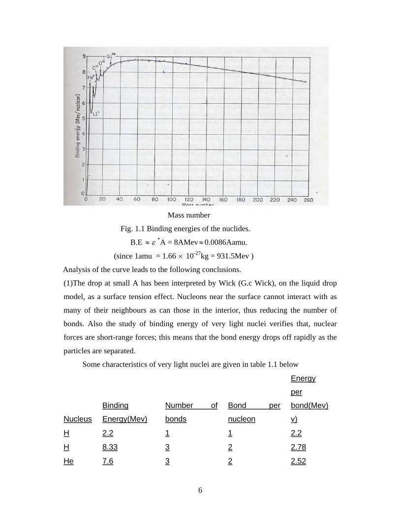
The plot of B*or ε against A is shown in the figure 1.1 below. From the figure 1.1 it
can be seen that ε (A) increases rapidly from ε = 0 for A = 1 to ε =8Mev for
A=16,passes through its maximum value ε max=8.8Mev for A ≈ 60(58Fe and 62Ni) and
then gradually decreases to ε =7.6Mev for the heaviest element encountered in nature,
namely uranium. The average value ε * is equal to 8Mevand ε =ε *=8Mev for most of
the nuclei. Hence, to a first approximation, the binding energy of atomic nuclei can be
expressed in terms of the mass number through the relation
6
Mass number
Fig. 1.1 Binding energies of the nuclides.
B.E ≈ ε *A = 8AMev ≈ 0.0086Aamu.
(since 1amu = 1.66 × 10⁻²⁷kg = 931.5Mev )
Analysis of the curve leads to the following conclusions.
(1)The drop at small A has been interpreted by Wick (G.c Wick), on the liquid drop
model, as a surface tension effect. Nucleons near the surface cannot interact with as
many of their neighbours as can those in the interior, thus reducing the number of
bonds. Also the study of binding energy of very light nuclei verifies that, nuclear
forces are short-range forces; this means that the bond energy drops off rapidly as the
particles are separated.
Some characteristics of very light nuclei are given in table 1.1 below
Nucleus
Binding
Energy(Mev)
Number of
bonds
Bond per
nucleon
Energy
per
bond(Mev)
v)
H 2.2 1 1 2.2
H 8.33 3 2 2.78
He 7.6 3 2 2.52
7
He 28.11 6 3 4.69
We see that the energy per bond increases as we go down the column. The bonds per
nucleon also increase as we go down the column, which suggests that the nucleons are
drawn together. [3] also we see that the peak at A = 4 corresponds to the exceptionally
stable 2He4 nucleus, the alpha particle.[5]
(2) The fact that B* or ε is nearly constant for intermediate masses allow us to say
that nuclear forces are saturated. i.e. the ability of a nucleon to interact not with all
nucleons surrounding it but just with a few of them. Indeed, if each nucleon in a
nucleus interact with all the (A-1) remaining nucleons, the total energy would be
proportional to A(A-1) ≈ A2 and not to A. Saturation is closely related to the short
range nature of nuclear forces.[4]
(3)The positive value of B.E and ε for all nuclei implies that nuclear forces are
attractive in nature, the energy of attraction being more than compensating the
coulomb repulsion by protons. Moreover, the large value of the average binding
energy per nucleon ε * = 8Mev means that nuclear interaction is extremely strong.[1]
(4)The binding energy ε per nucleon in a nucleus is a measure of its stability. The
value of ε is especially large in even-even nuclei (even z and even n),which include
the α -particle like nuclei 12C, 16O, etc (α -particle like nuclei are the ones containing
A = 4n nucleons, of which there are z = 2n protons & N = 2n neutrons n being an
integer).This circumstance indicates an additional (pairing) interaction between two
nucleons)[1],for all the bonds of the four particles are used.[4]
(5)Nuclei with an odd mass number, i.e. even-odd (even z and odd N) and odd even
(odd z and even N) nuclei have unpaired neutron (proton) and hence a somewhat
lower value of ε . Finally an odd- odd nuclei (odd z and odd N) are β -radioactive as
a rule, since they have two unpaired nucleons i.e. the lowest value of ε (only four
such β -stable nuclei are known:1H2, 3Li6,5B10 and 7N14.[1]
(6)A comparison of the value of ε for all even-even nuclei reveals that even against
the background of α -particle like nuclei with a high stability, there are still higher
values of ε for nuclei containing one of the following numbers of protons and/or
neutrons: 2 , 8 , 20 , (28) , 50 , 82 , 126 (the last number corresponds to neutron
only).These numbers are called magic nuclei. Nuclei having magic numbers of protons
8
and neutrons are called double magic nuclei. The unusually high stability of magic
nuclei is explained in the shell model of the nucleus. Nucleon shells for protons and
neutrons are filled independently. A simultaneous filling of proton and neutron shells
indicates the formation of especially stable double magic nuclei.[1]
1 . 4 Nuclear stability
Not all combinations of neutrons and protons form stable nuclei. In general light
nuclei (A ≤ 20) contain approximately equal numbers of neutrons and protons,[5]
while in heavier nuclei larger proportion of neutrons is required to produce increased
separation between the protons.[4] Nucleons, which have spin of ½, obey the pauli
exclusion principle. As a result each nuclear energy level can contain two neutrons of
opposite spins and two protons of opposite spins. Energy levels in nuclei are filled in
sequence just as energy levels in atoms are, to achieve configurations of minimum
energy and therefore maximum stability.[5]
Sixty percent of stable nuclides have both even Z and even N,[5] and
thereare 162 such stable nuclides. [4] Nearly all others have either even Z and odd N
or odd Z and even N with the number of 54 and 50 respectively.[4]Only five stable
odd- odd nuclei are known: 1H2 , 3Li6 , 5Be10 , 7N14 and 73Ta180.[5]
Nucleons inside the nucleus are more tightly bound than are those on the surface. In
light nuclei most or all of the nucleons are on the surface. This tends to make the very
light nuclides less stable than those of intermediate mass The very heavy nuclei are
less stable than those of somewhat smaller mass because of the large disruptive force
of their large electric charge. Nuclides of intermediate mass are therefore more stable
than either the very light or very heavy nuclides.[4]
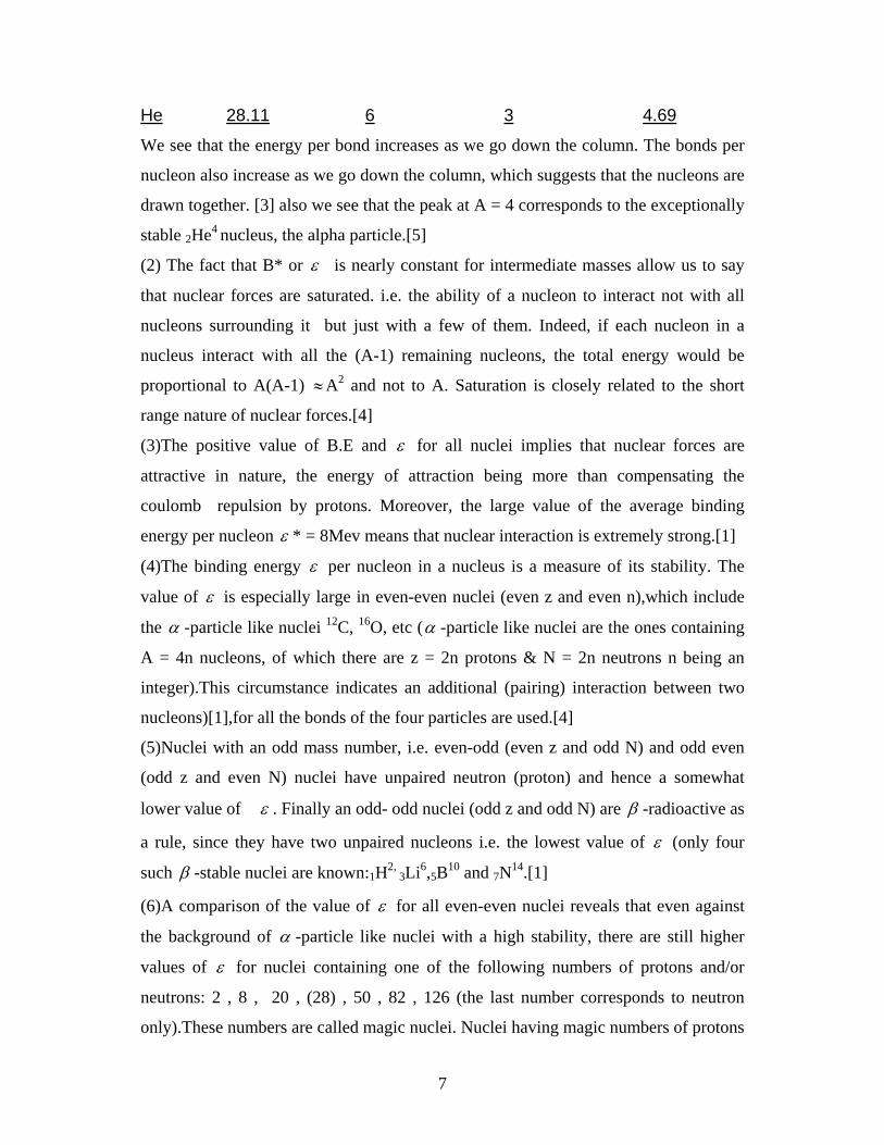
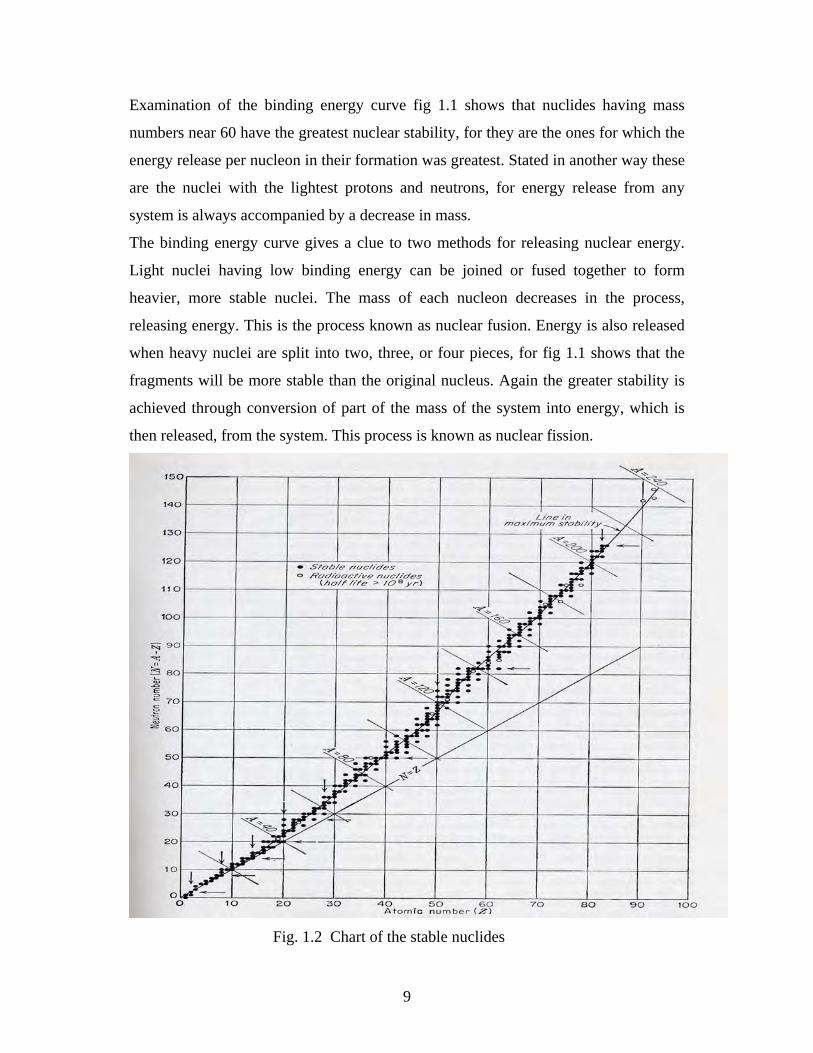
As shown in fig 1.2 at low Z values, stable nuclides contain roughly equal number of
protons and neutrons. Nuclides just above or below the line of stability are unstable
and decay by radioactive disintegrations, fission etc, while nuclides far from the line
of stability on the chart are not observed. The line of stability ends at Z=83 and
nuclides with atomic number greater than this are always unstable & undergo
radioactive decay. [2]
9
Examination of the binding energy curve fig 1.1 shows that nuclides having mass
numbers near 60 have the greatest nuclear stability, for they are the ones for which the
energy release per nucleon in their formation was greatest. Stated in another way these
are the nuclei with the lightest protons and neutrons, for energy release from any
system is always accompanied by a decrease in mass.
The binding energy curve gives a clue to two methods for releasing nuclear energy.
Light nuclei having low binding energy can be joined or fused together to form
heavier, more stable nuclei. The mass of each nucleon decreases in the process,
releasing energy. This is the process known as nuclear fusion. Energy is also released
when heavy nuclei are split into two, three, or four pieces, for fig 1.1 shows that the
fragments will be more stable than the original nucleus. Again the greater stability is
achieved through conversion of part of the mass of the system into energy, which is
then released, from the system. This process is known as nuclear fission.
Fig. 1.2 Chart of the stable nuclides
10
It is well known fact that all three radioactive families existing in nature
terminate at 82Pb. Among the nuclei encountered in nature those with Z ≤ 82 are as a
rule stable. Alpha particles with the highest energy (in comparison with the
neighbouring nuclei) are emitted by radioactive nuclei with N = 128 , Z = 84 and
N=84, which are transformed into the nuclei with N=126, Z=82 and N=82
respectively. Similarly, the highest energy of beta decay is observed in beta transitions
to magic nuclei, while the beta particle emitted by magic nuclei have the lowest
energy.[1]
CHAPTER TWO
RADIOACTIVITY
2.1 Discovery of Radioactivity
One of the most important discoveries in nuclear physics was made in 1896, quite by
accident. Wilhelm Rontegen had discovered x-rays the preceding year. Henri
Becquerel was trying to determine the relationship between the phosphorescence of
certain salts after exposure to sunlight and the fluorescence of the glass in an operating
x-ray tube. One of the salts used was potassium uranium sulphate,
K2UO2(SO4)2H2O.After exposing some of this salt to sun light, Becquerel found that
not only did it emit visible light, but also rays which, like x-rays, could penetrate
through thick black paper and thin metal foils exposing photographic plates wrapped
within. When cloudy weather intervened, he put the uranium salt and a photographic
plate away in a drawer to wait for sunny weather. Later this plate was developed, and
an intense image of the salt appeared although the salt had not been exposed to much
sunlight. Becquerel then conducted further experiments showing that the intensity of
the penetrating radiations was quite independent of any exposure to sun light and that
they came from uranium in the salt.[4] If it were not for the fact that a few very
long lived radio nuclides occur in nature, it is certain that radioactivity would not have
been discovered as early as it was. Natural thorium minerals contain 90 Th232 and
uranium minerals contain 92U235 and 92U238. The half lives of these naturally occurring
radio nuclides are comparable with or greater than the age of the earth (≈ 3×10⁹years).
It must be presumed, therefore, that when earth matter, as we now know it, was
11
created these radio nuclides were formed along with the stable nuclides and have been
decaying very slowly ever since. The shorter lived radio nuclides would have decayed
away long ago and are thus not found in nature.[2] Ernest Rutherford repeated
Becquerel’s experiments and showed that uranium emits two kinds of radiations,
which he called alpha and beta rays. Rutherford found that the alpha rays are absorbed
by very thin layers of matter, such as sheet of paper, but that the beta rays are able to
produce the effects discovered by Becquerel. A third still more highly penetrating
emission called gamma rays was discovered later. Rutherford’s investigations led,
several years later, to his nuclear model of the atom, and all three radiations were
shown to come from the nucleus. Marie curie discovered that thorium has about the
same degree of radioactivity, as does uranium. Her tests showed that the uranium ore,
pitchblende, contained considerably more radioactivity than could be expected from
its uranium content. She and her husband, Pierre, then succeeded in separating from
the pitch blende the previously unknown elements is over a million times more
radioactive than uranium.[4] therefore if uranium and thorium minerals were not
radioactive, we would probably not know much about nuclear physics today. [3]
2.2 General Properties of Radiations
Radioactivity is spontaneous emission of nuclear radiation by a substance. This
radiation occurs during α- or β- transformations of atomic nuclei as well as during
other nuclear decays, i.e. in transitions of excited nuclei into their ground energy
states, in spontaneous fission.[6] the basic properties of the three radiations are:
(1) from the deflection direction and the magnetic field direction, the α- and β-
radiations are streams of high speed positively and negatively charged particles
respectively. Further experiments involving the determination of charge to mass ratio
of these particles show that the α- particles are helium nuclei and that the β- particles
are negatrons. The third component called gamma radiation undeflected by a magnetic
field. The γ-rays were recognized early on as being electromagnetic waves and similar
to x-rays but with more energy.
12
(2) When the α-, β- and γ-radiations which occur in radioactivity are passed into
absorbing materials of different thickness, it is the gamma (γ) radiation which has the
greatest penetrating power while the alpha (α) radiation is the most easily absorbed.
(3) The γ-radiation is practically unaffected by paper and aluminium sheet and is
only partly absorbed by the lead. The β- radiation is hardly affected by the paper but is
absorbed by aluminium and lead. In general, the α- and β- radiations can be easily and
completely absorbed by relatively thin layers of any material while the γ- radiation is
never quite completely absorbed even by the very thick layers of the most dense
materials.
(4) When any radioactive radiation, but in particular α- or β- radiation is passed
through a gas, it produces ionization of the gas molecules. If the gas is enclosed
between two electrodes maintained at different potentials, an ionization current (I)
through the gas results.
2.3 Radioactive Decay Law
If any radioactive sample is examined for its radioactivity, it is always observed
that the strength or activity as measured by the rate of emission of α-, β- and γ-rays
decrease with time. The time taken for the activity to decrease to one half of its initial
value is called the half-life, T1/2, and is characteristic of each radionuclide.
Radionuclides are known with half-lives from 10-6 to 1010 years.
If at any time the number of radioactive atoms present is N(t), then it is an
experimental fact that the disintegration rate R,or rate of change of N(t) with time is
proportional to N, i.e. R = dt
tdN )( = - λ N……………………………………(2.1)
Where λ is the constant of proportionality, called the decay constant, and the negative
sign indicates that the number of atoms N, is decreasing with time. Integration of
Eq.2.1.yields directly the equation :
N = Noexp(- λ t)..……………………………………………(2.2)
Where No is the number of radioactive atoms at time t = 0, and N is the number at time
t. Then for half life T1/2 we have:1/2 No = Noexp(- λ T1/2) ⇒ T1/2 = λ
2ln
13
Or T1/2 = λ693.0 ………………………………………(2.3)
If the unstable nuclei of a given species were identical clock like mechanisms obeying
the laws of classical physics, we would expect all of them to decay at the same time
after their formation. Instead, they are found to decay after a wide range of different
times. The explanation of this behaviour lies in the probabilistic nature of quantum
mechanics.
Radioactivity is a property of nuclear state. It is impossible to affect the process of
radioactive decay without changing the state of the nucleus.consequently, the
probability, λ of radioactive decay per unit time is constant for a given nucleus, in a
given energy state (Isotope). Since λ is probability per unit time, λ dt is the
probability that any nucleus will undergo decay in a time interval dt. If a sample
contains N undecayed nuclei, the number dN that decay in a unit time dt is the product
of the number of nuclei N(t) and the probability, λ dt that each will decay in dt .
That is:
dN= - λ Ndt………………………………………(2.4)
where the minus sign is required because N(t) decreases with increasing time, t. the
disintegration probability λ appears in this equation as a coefficient called the decay
constant. Equation 2.4 can be rewritten as:
N
dN = - λ dt
and integrating both sides, ∫N
No
NdN / = - λ … ∫tdt
0 gives , lnN - lnNo = - λ t
i.e. N = Noe- λ t…………………………………(2.5)
this equation 2.5 which gives the variation of the number of radioactive nuclei with
time is known as the exponential radioactive decay law.
Since it is the activity or counting rate, (dtdN )which is observed rather than N,
differentiating equation 2.5 yields: dtdN = - λ Noexp(- λ t).
But (- λ No) is the initial activity Ro at time t = 0, so that:
14
R = ROexp(- λ t)…………………………………(2.6)
From equation (3.5), it follows that the process of radioactive decay is described by an
exponential function. Hence at any instant of time t, there always exist undecayed
nuclei with lifetime exactly equal to The number of these nuclei will be:
dn(t) = λ N(t) = λ No exp(- λ t)
We can calculate the average life time T of a given radioactive nucleus by calculating
the average value of t as:
T = t =
∫
∫∞
∞
0
0
)(
)(
tdN
ttdN =
No
dtttNo∫∞
−0
)exp( λλ
Putting x = λ t gives dx = dtλ , or dt = dx / λ , so that we have
T = λ1
∫∞
−0
)exp( dxxx = λ1
Or T = λ1 (2.7)
I.e. the average lifetime T of radioactive nucleus is the reciprocal of the decay
constant. Note also that we can write the decay law as:
N(t) = 2n
No (2.8)
Where n is the number of half lives in time t and n = t / T1/2 (since T1/2ln 2/ λ or
λ = ln2 / T1/2 and then exp (- tλ ) = exp(-tln2 / T1/2) = 2-t/T1/2)
There are several ways to characterize the rate at which a radioactive nucleus
decays. One is to give decay constant λ . The other is to give the reciprocal 1 / λ
which is denoted by T. putting t = T, into the equation (3.5) gives:
N = No / e (2.9)
i.e., T is the time in which N drops to the fraction of 1/e of its original value.
For a general case when unstable nuclei decays in more than one fashion (say by
beta decay as well as gamma decay) we denote the total decay constant λ as:
λ = λ 1 + λ 2 + λ 3 + (2.10)
15
Where λ 1, λ 2, λ 3 etc are partial decay constants of each specific mode. We can also
write a mean lifetime T (T = 1 / λ ) as:
1/T = 1/T1 + 1/T2 + 1/T3 + (2.11)
and call T as the total mean life time and T1, T 2, T3 etc as partial mean life times.[9]
if in turn the nuclei N2 appearing as a result of radioactive disintegration
of nuclei N1, are also radioactive , we must write a system of two differential
equations to describe these two successive transformations instead of single
differential equation. I.e. dN1(t) / dt = - λ 1N1(t)
dN2(t) /dt = λ 1N1(t) - λ 2N2(t) (2.12)
Where λ 1and λ 2 are disintegration constants of nuclei N1 and N2 respectively. The
system of equations describing the mutual transformation of three, four, or more
substances can be also written in an exactly similar manner. Solving this system of
equations (3.12), we obtain the following result.
N1(t) = N01 exp(- λ 1t)
N2(t) = N02exp(- λ 2t ) + λ 1N01 / ( λ 2 - λ 1)[exp(- λ 1t) – exp(- λ 2t)] (2.13)
Where N01 and N 02 are the values of N1(t) and N2(t) at t = 0. expressions (3.13) are
considerably simplified if T1 >> T2 ( λ 1 << λ 2) and time periods t << T1 are
considered. in this case N1(t) ≈ N01
N2(t) ≈ N02 exp( - λ 2 t ) + λ 1N 01 / λ 2[1 - exp(- λ 2 t) ] (2.14)
If N02 = 0,we get N2(t) ≈ λ 1N 01 / λ 2 (1 - exp( λ 2t ) (2.15)
Then in the limiting case we get:
lim)t→ ∞ N2(t) = λ 1N 01 / λ 2 = const
or λ 1N 1 / N2 λ 2 (2.16)
and this is called the secular equation. This indicates that the number of
disintegrations, N2 λ 2 of the daughter material is equal to the number of
disintegrations of the parent substance- which is secular equilibrium condition. This
equation can be used to compare two interconvertible substances where half life of the
second substance being much smaller than the first (T2 << T1). Under the condition
that this comparison is made at the instant t >>T2 (T2 << t << T1)
Some of the more often used units characterizing the activity are
16
1Curie = 1Ci = 3.7 x 10 10 disintegrations / second
1Rutherford = 1R = 10 6 dis / sec
1Becquerel = 1Bq = 1dis / sec [13]
2..4 NUCLEAR RADIATIONS
2.4.1 INTRODUCTION
The three common radiations from radioactive elements are alpha beta and gamma
radiations. It was shown that the alpha particle is identical to helium nucleus, beta
radiation consists of electrons, and that gamma radiation is electromagnetic wave. In
natural radionuclides, alpha process and beta processes very often compete, that is
they may both be energetically possible. Whether or not a given nuclide is observed to
be simultaneously an alpha emitter and beta emitter depends on whether the
probabilities of occurrence of the two processes are sufficiently close in order of
magnitude.[7]
2.4.2 ALPHA- DECAY
Alpha rays are positively charged particles and are identical with doubly ionized
helium atoms (He++). They are emitted by nuclei as a result of alpha decay. Mostly
heavy nuclei (Z > 82) undergo natural alpha decay. Usually alpha decay is
accompanied by beta decay and/or gamma decay. In alpha decay, parent nucleus
transforms into a daughter nucleus and an alpha particle; thus the mass number of the
parent nucleus decreases by four units while atomic number decreases by two units.[9]
The decay process is written schematically as:
ZXA Z-2YA-4 + 2α 4 ------------------2.18
Where X and Y are the initial and final nuclear species [11]
ENERGETICS OFALPHA DECAY: The energy mass equation for α -decay
can be written as: Mc2 = M1c2 + mac2 + Qa
where M&M1 are the representative masses of parent nucleus and daughter nucleus.
Or Qa = (M – M1 - ma)c2 (Q – equation) ----------2.19
17
`Where Q is called the nuclear disintegration energy. Hence the possibility of α -
decay interms of mass is expressed by the relation M > M1 + ma (i.e. Qa > 0)
---2.20
(i) From the conservation of momentum we can see that, the daughter nucleus M1,
recoils with equal momentum as alpha particle:
i.e. Pa = PM-1 or mava = M1v1
and then v1 = mava/M1
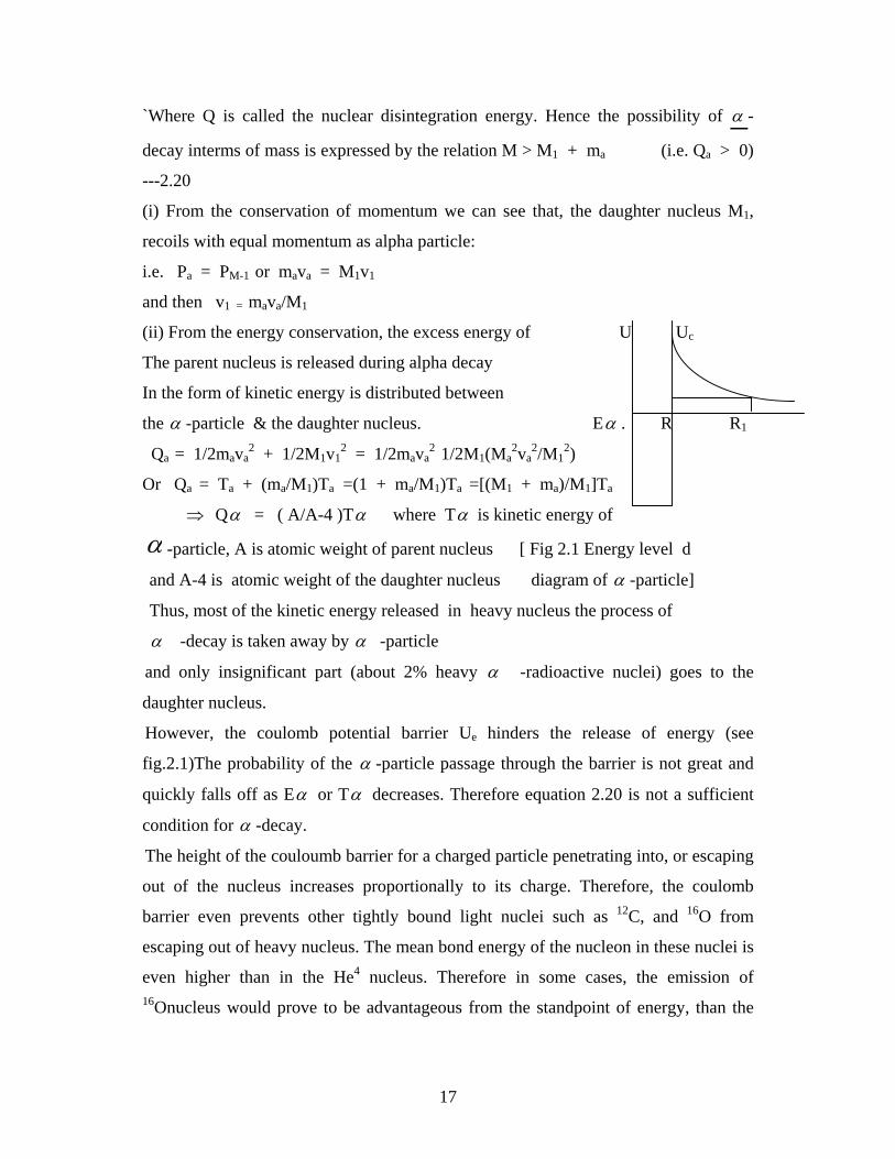
(ii) From the energy conservation, the excess energy of U Uc
The parent nucleus is released during alpha decay
In the form of kinetic energy is distributed between
the α -particle & the daughter nucleus. Eα . R R1
Qa = 1/2mava2 + 1/2M1v1
2 = 1/2mava2 1/2M1(Ma
2va2/M1
2)
Or Qa = Ta + (ma/M1)Ta =(1 + ma/M1)Ta =[(M1 + ma)/M1]Ta
⇒ Qα = ( A/A-4 )Tα where Tα is kinetic energy of
α -particle, A is atomic weight of parent nucleus [ Fig 2.1 Energy level d
and A-4 is atomic weight of the daughter nucleus diagram of α -particle]
Thus, most of the kinetic energy released in heavy nucleus the process of
α -decay is taken away by α -particle
and only insignificant part (about 2% heavy α -radioactive nuclei) goes to the
daughter nucleus.
However, the coulomb potential barrier Ue hinders the release of energy (see
fig.2.1)The probability of the α -particle passage through the barrier is not great and
quickly falls off as Eα or Tα decreases. Therefore equation 2.20 is not a sufficient
condition for α -decay.
The height of the couloumb barrier for a charged particle penetrating into, or escaping
out of the nucleus increases proportionally to its charge. Therefore, the coulomb
barrier even prevents other tightly bound light nuclei such as 12C, and 16O from
escaping out of heavy nucleus. The mean bond energy of the nucleon in these nuclei is
even higher than in the He4 nucleus. Therefore in some cases, the emission of 16Onucleus would prove to be advantageous from the standpoint of energy, than the
18
successive escape of four alpha particles. However, the escape of the nuclei heavier
than He4 nucleus has not been observed.
2.4.2 Mechanisms of α -decay
From the point of view of classical physics, a body with energy Eα ( ≈ 4Mev) being
in the region 0 ≤ r ≤ R separated from the outer space by an energy barrier of the
height Uc and width R1 – R, can never be beyond this region because on reaching the
coordinate r = R, the kinetic energy of the body becomes equal to zero and its further
motion into the region r > R ceases. The only possible way to leave the potential is
to get such a quantity of energy ΔE from outside that the total energy of the body E +
ΔE ,becomes greater than the height of the barrier Ue.
The potential energy curve has a peak at r = R, called the coulomb potential
barrier. Hence it is not surprising that α - decay does not occur instantaneously. What
is surprising is the fact that it does occur at all, since the overcoming of a coulomb
barrier of height Uc> 8.8Mev by an α - particle with a kinetic energy of 4Mev is
forbidden in classical physics. Only quantum mechanics explains the α -decay
mechanism. Actually in the world of microscopic particles (electrons, nucleons, α -
particles) whose motion is described by quantum mechanics rather than by classical
physics, there exists a possibility of the passage of a particle through a potential barrier
– which is called tunneling.[1] Thus a particle possessing wave properties may be
beyond the potential well even when its total energy Eα < Uc.
In nuclides with high atomic number, the mutual electrostatic repulsion of the protons
is a powerful force tending to tear the nucleus apart. As a result, many of the heavier
nuclei tend to stabilize by emitting part of their charge in the form of an alpha particle.
For example when uranium-235 emits an alpha particle, thorium-231 is formed
according to the equation: 92U235 90Th 231 + 2He4 + γ + 4.67Mev.
Where the 4.67Mev of energy is liberated in the reaction corresponds to a 0.00502amu
decrease in the mass of the products as compared to the parent nucleus. Typical alpha
emitter (source) with no gamma radiation is francium-220.
87Fr220 85At216 + 2He4 6.81Mev
19
Here all the energy is carried by the particles as kinetic energy. The kinetic energy is
divided in inverse proportion to the mass of the particles; so that alpha particle takes
(216/220)6.81 = 6.69Mev and the remaining
(4/220)6.81 =.124Mev goes for the recoiling nucleus.
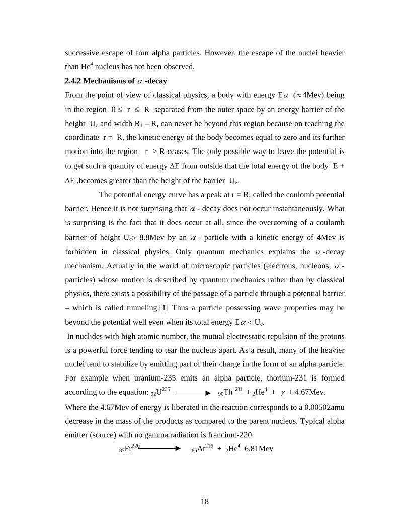
With many alpha emitters, all emitted alpha particles have exactly the same
energy. Nearly all of the alpha particles have energy greater than 4Mev.[12] A
plot of alpha rays emitted per unit time against Eα the energy of alpha rays is
called alpha ray spectrum and it usually shows a plot of similar to figure 2.2
Fig. 2.2 Alpha ray spectrum
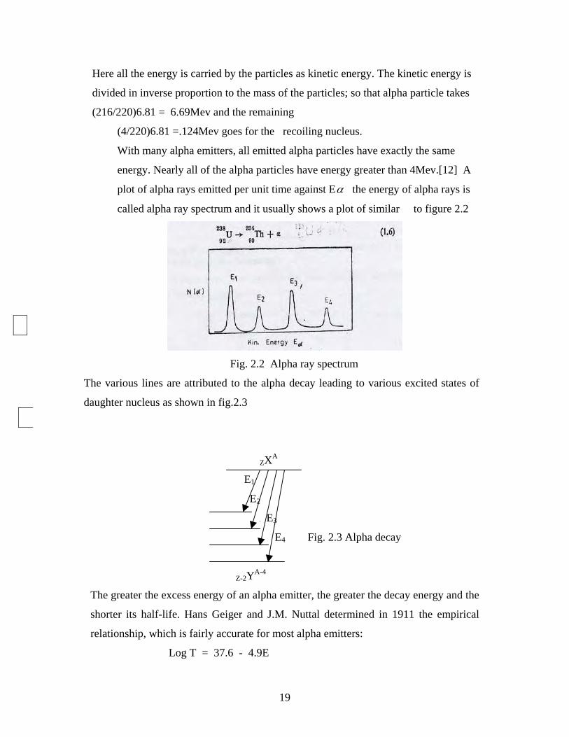
The various lines are attributed to the alpha decay leading to various excited states of
daughter nucleus as shown in fig.2.3
ZXA
E1
E2
E3
E4 Fig. 2.3 Alpha decay
Z-2YA-4
The greater the excess energy of an alpha emitter, the greater the decay energy and the
shorter its half-life. Hans Geiger and J.M. Nuttal determined in 1911 the empirical
relationship, which is fairly accurate for most alpha emitters:
Log T = 37.6 - 4.9E
20
Where T is a half life (sec) and E is alpha particle energy in Mev.
Also one may wonder why alpha particles rather than the protons/neutrons are emitted
by heavy nuclei. This is of course due to the binding energy. The binding energy of
the alpha particle is nearly as large as the binding energy of heavy nuclides, but the
proton/neutron binding energy is zero. In terms of mass, the protons/neutrons in alpha
particles are only slightly more massive than those in heavy nucleus, but an isolated
proton/neutron is considerably more massive. As a result an alpha particle needs to
acquire only a small amount of mass(energy) from the balance of the nucleus to be
emitted, while a proton would have to acquire considerably more mass (energy) for
emission to be possible.
2.5.2 Beta Decay
Many nuclides decay by an electron emission, positron emission, and orbital electron
about energy levels and decay schemes of light and intermediate weight nuclide as
well as those in the region of natural radioactive elements can be obtained by studying
β -decay.[12]
2.4.2.1 Energetics of Beta decay
There are three types of beta decay. These are (i) β - -decay, (ii) β +-decayand (iii)
electron capture (K-capture)
(i) A parent atom ZXA will be transformed during the β --decay according to the
equation: ZXA z+1YA + β - + Qβ-
The energy liberated in the β -- decay process (Q-equation) can be written as:
Mnc2 = Mn‘c2 + mec2 +Qβ
Or Qβ- = [ Mn - Mn‘ - me ]c2
Adding Zme to the respective nuclear masses, equivalently interms of the
mass of the atoms we can write :
Q β - =[(Mn + zme) - (Mn‘ + zme + me) ]c2
=[M(A,Z) - M(A,Z+1)]c2
Hence the energy condition for the possibility of the β --decay process is :
M(A,Z) > M(A,Z+1) (since Qβ- has has to be positive).
21
(ii) For β+-decay process also we can write an equation:
ZXA Z-1YA + β + + Qβ+
The energy liberated or the Q –equation for the process can be written as:
Mnc2 = Mn/c2 + mec2 + Qβ+
Or Qβ+ = [ Mn - Mn/ - me]c2
Again adding zme to both nuclei, we can go over from nuclear masses to atomic
masses as: Qβ+ = [(Mn + Zme) – (Mn// +me + Zme)]c2
Qβ+ = [(Mn(A,Z) + Zme) – (Mn(A,Z-1) +(Z-1)me + 2me)]c2
= [M(A,Z ) – M(A,Z-1) – 2me]c2
Then the energy condition for the β +- decay can be written in analogy to the β --
decay as : M(A,Z) > M(A,Z-1) + 2me (For Qβ+ to be positive)
(iii) The third type of beta radioactivity is electron capture (EC) involves the capture
of an electron by the nuclei from its own electron shell.[1] This is an alternative mode
of decay to positron emission and again causes an increase in the neutron to proton
ratio of emitting nucleus.[2]
A parent atom ZXA will be transformed during this decay (EC) according to the
equation: ZXA + e Z-1YA (EC decay ). [9]
Then the energy released during electron capture (EC) is given by:
Mnc2 + mec2 = Mn‘c2 + QEC
Or QEC = [Mn(A,Z) + me - Mn(A,Z-1)]c2
Adding the mass of Z-electrons to both nuclei, we get :
QEC =[Mn(A,Z) + Zme + me –(Mn(A,Z-1) + (Z-1)me + me)]c2
= [M(A,Z) – M(A,Z-1)]c2..[9]
The energy condition for the electron capture is:
Mn(A,Z) + me > Mn(A,Z-1)
Or M(A,Z) > M(A,Z-1)
The phenomenon of electron capture is quite significant for heavy nuclei whose k-
shell is quite close to the nucleus. Besides the capture of an electron from the k-shell
(k-capture), capture from L-shell (L-capture), capture from M-shell (M- capture)
22
(Of course with relatively less binding energy) are also observed.[1] The vacancy left
behind in the k-shell etc is followed by higher orbital electrons cascading down with
the emission of x-ray lines characteristic of the newly formed daughter atom (A,Z-
1).The x-ray emission is the net result and the only observable phenomenon associated
with the electron capture process.[2]
Finally, the fact that positrons and negatrons are emitted by the nuclei doesn’t mean
that they are present in nuclei as such. Their ejection results from an unknown process,
but is due to an unstable ratio of neutrons to protons in nuclei. If the number of
neutrons, (A-z) is greater than the number of protons, (z), an excess of neutrons can
lead to negatron emission with net result of a decrease in the neutron to proton ratio
i.e. 0n1 1p1 + β -
Similarly deficiency of neutrons can lead to positron emission, by which process the
neutron to proton ratio increases. I.e. 1P1 0n1 + β -
I n the electron capture process the nucleus captures one of the inner orbital electrons,
usually a k-shell electrons, which effectively converts one of the nuclear protons into a
neutron. I.e. 1P1 0n1.
2.4.2.2 The Neutrino Hypothesis
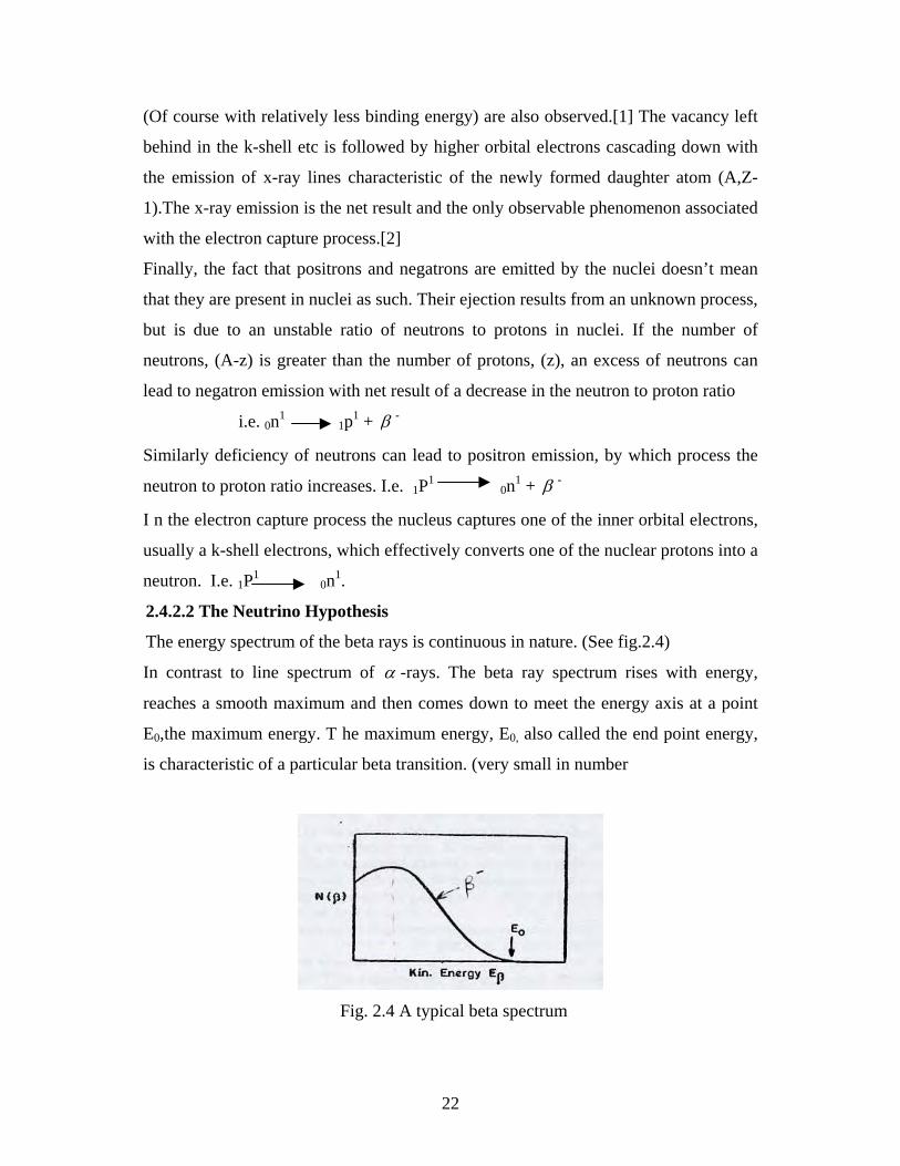
The energy spectrum of the beta rays is continuous in nature. (See fig.2.4)
In contrast to line spectrum of α -rays. The beta ray spectrum rises with energy,
reaches a smooth maximum and then comes down to meet the energy axis at a point
E0,the maximum energy. T he maximum energy, E0, also called the end point energy,
is characteristic of a particular beta transition. (very small in number
Fig. 2.4 A typical beta spectrum
23
The change of mass in any beta decay process is found to correspond to the sum of the
maximum energy carried by any beta particle plus the emitted gamma ray (if any).The
question then arises as what happens to the balance of the energy when beta particles
having less than the maximum energy are emitted? Also protons, neutrons and
electrons spin about their axes with an angular momentum given by 1/2 η . How then
can angular momentum be conserved in beta emission, when a new particle (the
electron) is suddenly created? The answer to these questions were suggested by
Wolfgang Paul in 1927
In the investigations of the properties of elementary particles W.Pauli,
theoretically predicted the existence of new particle namely neutrino – in 1931. By
considering the beta decay of atomic nuclei, Pauli arrived at the conclusion that the
existence of neutrino is inevitable. Ofcourse its existence was proved experimentally
later. In the above discussion we have seen that beta energy spectrum is continuous
where the energy from mass difference is fixed. Also the elementary act of beta decay
seemed to violate simultaneously the laws of conservation of energy, momentum and
angular momentum.
Inorder to explain the continuous nature of beta spectrum and to rescue the
conservation laws, Pauli proposed that the emission of an electron(positron) during the
beta decay of a nucleus is accompanied by the simultaneous emission of a neutral
particle with a mass equal to zero and with a half integral spin.
It was agreed to call the particle formed together with a positron during the
β +decay: (A,Z) (A,Z-1) + e+ + ve , the electron neutrino (ve) and the
particle formed together with the electron during the β - -decay :
(A,Z) (A,Z+1) + e- + ν e, the electron anti neutrino(ν e)
The first process is reduced to the transformation of a nuclear proton into a neutron as
Per decay scheme: P n + e+ +νe.
While the second process is reduced to the transformation of a nuclear neutron into a
proton: n P + e- + νe
Note the only difference between neutrino and antineutrino is in their helicity, i.e.
right handedness (νe) and left handedness (νe)
Finally from neutrino hypothesis we have the following results.
24
(i) Energy is conserved since now there is another particle (neutrino/antineutrino) is
emitted in each cases of beta decay. Thus we have, Eν = Emax - Eβ
I.e. if Eβ = Emax then Eν = 0 and Eβ = 0 for Eν = Emax.. Therefore this solves
the question of β - energy spectrum and its conservation.
(ii) Angular momentum is also conserved. For example in 1H3 2He3 + β- + ν
(iii) Linear momentum is also conserved due to the presence of neutrino.
2.4.2.3. Energy levels and Decay schemes
Beta transformations often yield information about the energy levels of the
product nuclei and about decay scheme. These transformations are
sometimes accompanied by γ - rays, and the presence of γ – radiation
means that the product nucleus is formed in an exited state and pass to
its ground state by emitting one or more γ - rays. If no γ -ray is emitted,
the β -transition is directly to the ground state of the product nucleus.
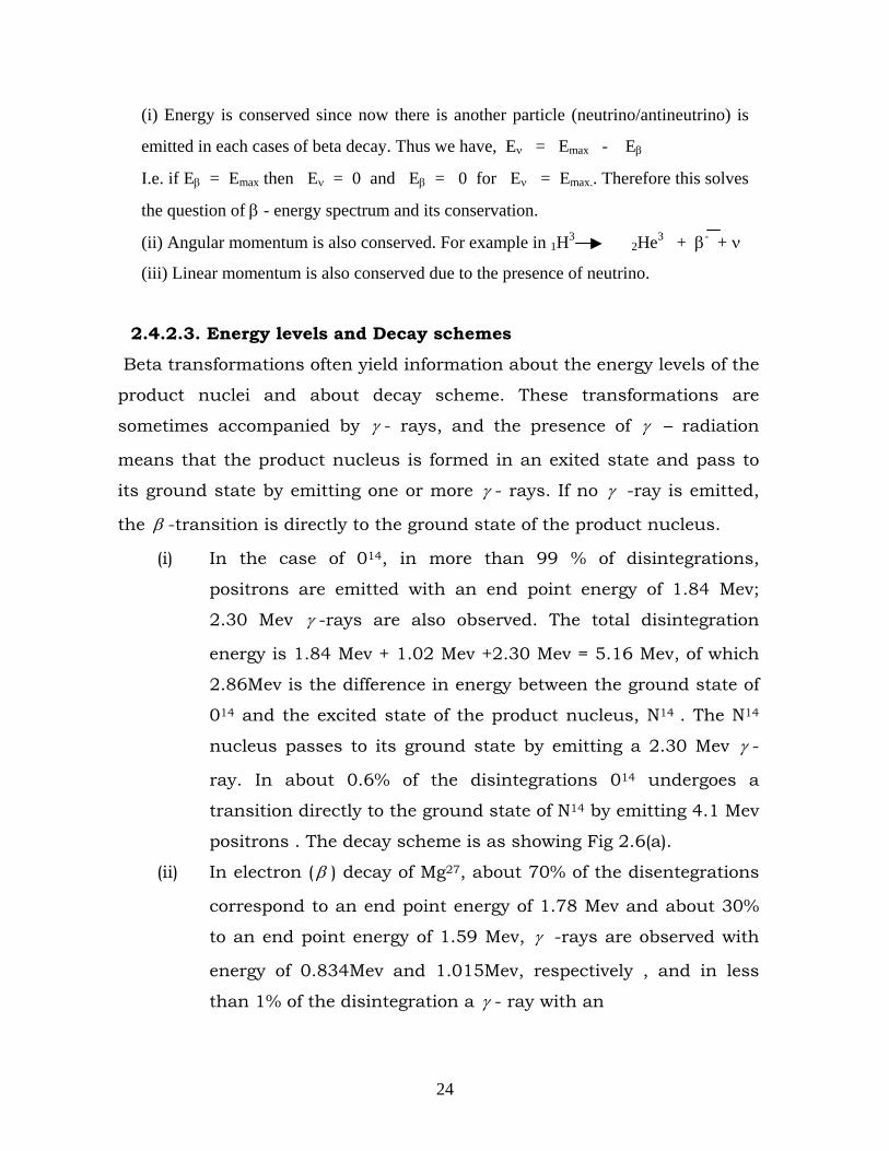
(i) In the case of 014, in more than 99 % of disintegrations,
positrons are emitted with an end point energy of 1.84 Mev;
2.30 Mev γ -rays are also observed. The total disintegration
energy is 1.84 Mev + 1.02 Mev +2.30 Mev = 5.16 Mev, of which
2.86Mev is the difference in energy between the ground state of
014 and the excited state of the product nucleus, N14 . The N14
nucleus passes to its ground state by emitting a 2.30 Mev γ -
ray. In about 0.6% of the disintegrations 014 undergoes a
transition directly to the ground state of N14 by emitting 4.1 Mev
positrons . The decay scheme is as showing Fig 2.6(a).
(ii) In electron ( β ) decay of Mg27, about 70% of the disentegrations
correspond to an end point energy of 1.78 Mev and about 30%
to an end point energy of 1.59 Mev, γ -rays are observed with
energy of 0.834Mev and 1.015Mev, respectively , and in less
than 1% of the disintegration a γ - ray with an
25
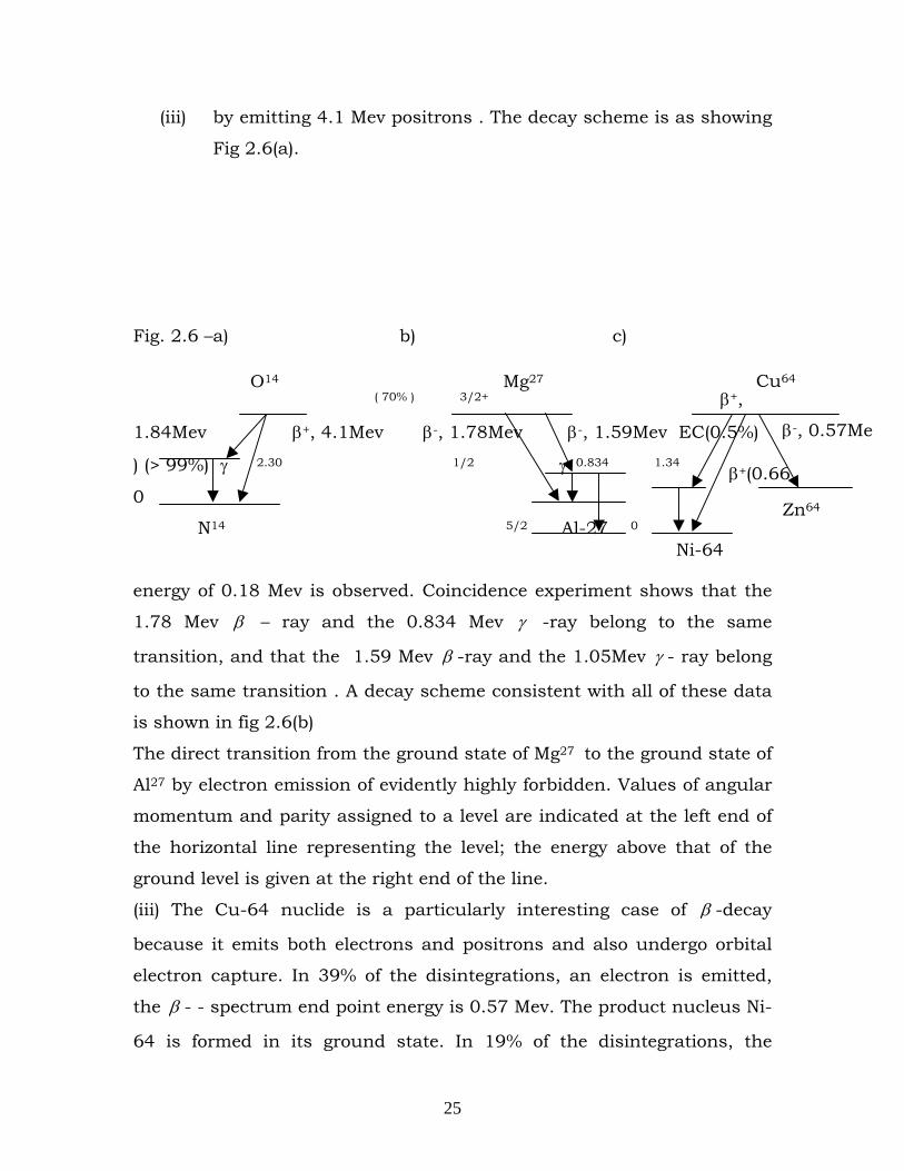
(iii) by emitting 4.1 Mev positrons . The decay scheme is as showing
Fig 2.6(a).
Fig. 2.6 –a) b) c)
( 70% ) 3/2+ 1.015 β+,
1.84Mev β+, 4.1Mev β-, 1.78Mev β-, 1.59Mev EC(0.5%)
) (> 99%) γ 2.30 1/2 γ 0.834 1.34
0
N14 5/2 Al-27 0
energy of 0.18 Mev is observed. Coincidence experiment shows that the
1.78 Mev β – ray and the 0.834 Mev γ -ray belong to the same
transition, and that the 1.59 Mev β -ray and the 1.05Mev γ - ray belong
to the same transition . A decay scheme consistent with all of these data
is shown in fig 2.6(b)
The direct transition from the ground state of Mg27 to the ground state of
Al27 by electron emission of evidently highly forbidden. Values of angular
momentum and parity assigned to a level are indicated at the left end of
the horizontal line representing the level; the energy above that of the
ground level is given at the right end of the line.
(iii) The Cu-64 nuclide is a particularly interesting case of β -decay
because it emits both electrons and positrons and also undergo orbital
electron capture. In 39% of the disintegrations, an electron is emitted,
the β - - spectrum end point energy is 0.57 Mev. The product nucleus Ni-
64 is formed in its ground state. In 19% of the disintegrations, the
β+(0.66
β-, 0.57Me
O14
Ni-64
Zn64
Cu64 Mg27
26
positron is emitted with an end point energy of 0.66 Mev; the product
nucleus Ni 64 is formed in its ground state. In 42% of this
disintegrations, a k-electron is captured. In nearly all of the captures, the
product nucleus, Ni 64 is formed in to ground state, but in a small
fraction of the k-capture, a γ -ray is observed with an energy of 1.34Mev.
There is, therefore, an excited level of Ni 64, 1.34Mev above the ground
state. It has been shown that the γ -ray is observed only in coincidence
with the orbital electron capture, and it is not associated with the
emission of either the electron or the positron. The decay scheme of Cu
64 is shown in fig 2.6(c).
2.4.3 Gamma Radiation
2.4.3.1 Nature of Gamma Radiation
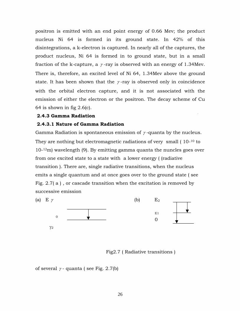
Gamma Radiation is spontaneous emission of γ -quanta by the nucleus.
They are nothing but electromagnetic radiations of very small ( 10-10 to
10-12m) wavelength (9). By emitting gamma quanta the nuncles goes over
from one excited state to a state with a lower energy ( (radiative
transition ). There are, single radiative transitions, when the nucleus
emits a single quantum and at once goes over to the ground state ( see
Fig. 2.7( a ) , or cascade transition when the excitation is removed by
successive emission
(a) E γ (b) E2
γ2
Fig2.7 ( Radiative transitions )
of several γ - quanta ( see Fig. 2.7(b)
E1
0 0
27
Hence gamma radiation is a short wave electro magnetic radiation of
nuclear origin whose energy usually varies from leker to 5 mcv in the
electromagnet de exation process the nuclear drops to a lower edxcited
state or to the ground state, in exact analogy with the emission of light
from excited atoms how ever, the emerges of the electromagnitivc quanta
emited by nuclei are mostly in the range 1014 to 106 times the energy of a
photos in the usable aspect rum.
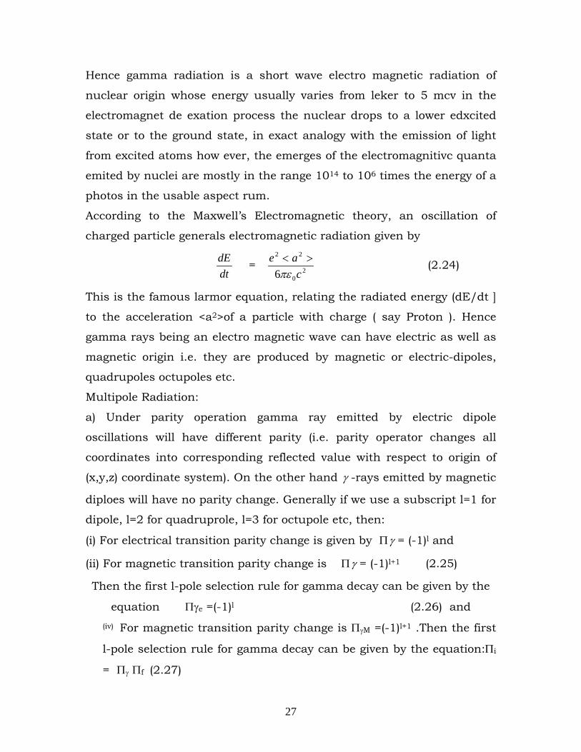
According to the Maxwell’s Electromagnetic theory, an oscillation of
charged particle generals electromagnetic radiation given by
dtdE = 2
0
22
6 cae
πε>< (2.24)
This is the famous larmor equation, relating the radiated energy (dE/dt ]
to the acceleration <a2>of a particle with charge ( say Proton ). Hence
gamma rays being an electro magnetic wave can have electric as well as
magnetic origin i.e. they are produced by magnetic or electric-dipoles,
quadrupoles octupoles etc.
Multipole Radiation:
a) Under parity operation gamma ray emitted by electric dipole
oscillations will have different parity (i.e. parity operator changes all
coordinates into corresponding reflected value with respect to origin of
(x,y,z) coordinate system). On the other hand γ -rays emitted by magnetic
diploes will have no parity change. Generally if we use a subscript l=1 for
dipole, l=2 for quadruprole, l=3 for octupole etc, then:
(i) For electrical transition parity change is given by Πγ = (-1)l and
(ii) For magnetic transition parity change is Πγ = (-1)l+1 (2.25)
Then the first l-pole selection rule for gamma decay can be given by the
equation Πγe =(-1)l (2.26) and (iv) For magnetic transition parity change is ΠγM =(-1)l+1 .Then the first
l-pole selection rule for gamma decay can be given by the equation:Πi
= Πγ Πf (2.27)
28
Where the subscripts i and f stand for initial and final states.
(b) When transition takes place from an initial state of total angular
momentum, Ii to a state of angular momentum If, then the difference in
angular momentum is associated with gamma. As angular momentum is
quantized gamma may have any value of l, l=0,1,2,---- and a selection
rule II based on the change in I-value can be written as:
/If-Ii/ < l < If+Ii (2.28)
Where l being an angular momentum, l= 1,2,3 --- Shows the multipolity
of the electric (El) or magnetic (Ml) transitions.
The first excited state of 60 -Co is 4+ state at 2.505 Mev. It decays to 2+
state at 1.332 Mev. Via E2 transition since the transition with the lowest
l-value is faster than the others by several orders of magnitude (where 2<
l <6) and no parity change (+ to +) (see fig )
2.4.3.2 Energetics of Gamma decay
(kinematics of photon Emission)
Emission of energetic photon – gamma radiation – is typical for a nucleus
de exciting from some high – lying excited state to the ground state
configuration. These transmutations take place within the same nucleus
ZXA in contrast to beta decay and alpha decay processes . They merely
represent a re- ordering of the nucleons with in the nucleus with a
lowering of mass from the excited ( M* C2) to the lowest (MoC2 ) Value .
The total energy balance then reads .
M0 * C2 = Mo C2 + Eγ + T0 (2.29)
With Eγ the energy of the emitted photon and T0 the Kle of the recoiling
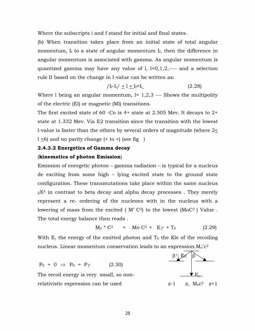
nucleus. Linear momentum conservation leads to an expression.Mo*c2
β+; Ec β-
P0 = 0 ⇒ P0 = Pγ (2.30)
The recoil energy is very small, so non- Eγ
relativistic expression can be used z-1 z, Moc2 z+1
29
i.e.T0 = Po2/2Mo =Pγ2/2Mo=Eγ2/2Moc2 ,since Pγ = Eγ/c (2.31)
Fig.2.8
2.4.3.3 The Nuclear Deexcitation mechanisms
Nuclear in highly excited states most often de excite themselves by the
emission of heavy particle, whenever this is energetically possible.
Particularly when the energy of excitation of nuclei is below the nucleon
binding energy, nucleon emission is not observed. In such a case either
gamma decay or another phenomena – internal conversion (IC), (some
times) or pair production (with small probability) may take place.
(i) Gamma Decay: Gamma decay is a natural radioactive
phenomenon, which is observed just like other decay as, α and
β – decay. This is also observed when excited state of nucleus
produced in nuclear reaction decides to ground state.
(ii) Electron of internal conversion: Sometimes it is possible for
nuclear excitation energy to be removed by ejection of an atomic
electron of internal conversion. The coalomb field of the nucleus
transfers all of the excitation energy directly to the atomic
electron, causing it to move in to unbound state with an energy
balance of Te = (Ei –Ef) – En
or = E* -En (2.32)
where E* or = Ei –Ef is the nuclear excitation energy, En is the
binding energy of electrons in the corresponding shells of the atom,
and Te is the electron Kinetic energy. The energy is transmitted
mainly through the columb interaction and a larger probability for k-
electrons will result because k-electrons have a non-vanishing
probability of coming into nuclear interior.
The total probability per unit time of decay of excited
nucleus is given by Γ/h, where we write for bound state
Γ=Γγ + Γe (2.33)
30
which Γ is the width for emission of electron and Γ is width for r-
emission. In both cases the total energy of nuclear excitation is
removed and the two process must be regarded as competing
alternatives. If the number of electrons observed per excited nucleus
is Ne and the number of γ-rays is Nγ we define the internal conversion
coefficient,α and as: α = Ne /Nγ = Γe/Γγ (2.34)
Where α may have any value between zero and infinity. The absolute
value of the coefficient α is the higher, the longer the lifetime with
respect to the emission of a γ -quantum, and the higher z of the
nucleus. i.e. the close the electron shells of the atom to the nucleus.
X-radiation and Auger electrons
As a result of emission of the electron of internal conversion, the
atomic nucleus passes to its ground state. The ground state by
definition, is the neutral atom with all electrons in the lowest possible
state. The atom, however, remains excited because of the lack of an
electron in one of its shells. When a hole has been created in the 1s
state, for instance, an electron from another state will drop down and
fill the hole. Therefore, the emission of the internal conversion
electron is accompanied by the radiation of the characteristics x-ray
quanta or by the emission of the auger electrons.
The emission of the electron of internal conversion is most probable from
the k-shell. In this case, the excitation energy of the atom is equal to the binding
energy of the lost electron, Ek. Filling the vacancy in the K-shell occurs mainly in the
transition of the electron from the nearest L- shell and the atom emits a Kα x-ray
quantum. (The transitions are labeled Kα for transitions to L levels Kβ for transitions
to the M levels, and Kγ for transitions to the N- levels) When a hole is created in the
L- Shell and the atom emits Kα radiation, an electron from the M,N,or O shells etc
has much lower energy than the K radiation. Hence one electron hole, Originally, in
the K shell, , for instance, may produce a cascade of x – ray , with rapidly decreasing
quantum energies. In competition with this series of events is another interesting
31
process called auger effect in this process the available energy released in K to L
transition is used not to emit a photon but to eject another L- electron. Hence two
holes appear in the L- shell, more auger electrons and / or L- radiation etc. follow
Conversion with pair production: one more mechanism of releasing the excess energy
from the nucleus is called conversion with pair production. If the excitation energy of
the nuclear exceeds 1.02 Mev (E*>2mc2) this is the coulomb field of the nucleus, an
electron – positron pair may be produced as an alternative to γ-ray emission and
electron internal conversion i.e. excited nucleus may emit a positron – electron pair
which carries off all its excitation energy. As the emission of conversion electrons,
conversion with pair production is not the conversion proper. i.e. is not the trans
formation of a γ – quantum, previously emitted from the nucleus, into an electron
positron pair, but is an additional method of giving off the nuclear energy into the
outer space. The probability of this process is always low in comparison with the
probability of emitting a γ – quantum. In contrast to the internal conversion
coefficient, the probability of conversion with pair production is slightly lower with
the increase of Z of the nucleus as well as with increase of the nuclear transition
multipolarity (its being produced by diploe (l=1), quadrupole (l=2) or higher poles)
the kinetic energy released in the process of pair production, Epair = E* - 2mc2, is
distributed between the electron, the position and the remaining of atom.
2.4.3. Sources of Gamma rays
In radioactive decay, daughter nucleus is usually left in an excited
state as a result of the alpha or beta decay of the parent nucleus.
Subsequently the daughter nucleus de-excites from these higher
levels by emitting gamma rays. Thus, gamma rays usually follow the
alpha or beta decay.(1) Alpha decay: In most (normal) cases of α-
decay, the excess energy of the parent nucleus is released in the form
of kinetic energy. i.e. Eα =Tα +Tnuc, which is distributed between
alpha particle and daughter nucleus. But alpha spectra frequently
contain groups of alpha particle with lower (fine structure of alpha
spectra) and sometime even higher (Long range alpha particle)
energies as compared to the normal α - decay.
32
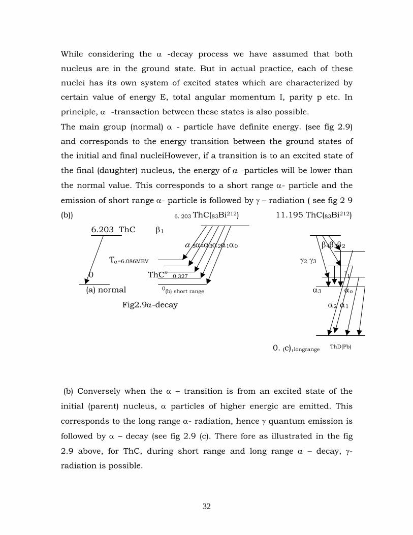
While considering the α -decay process we have assumed that both
nucleus are in the ground state. But in actual practice, each of these
nuclei has its own system of excited states which are characterized by
certain value of energy E, total angular momentum I, parity p etc. In
principle, α -transaction between these states is also possible.
The main group (normal) α - particle have definite energy. (see fig 2.9)
and corresponds to the energy transition between the ground states of
the initial and final nucleiHowever, if a transition is to an excited state of
the final (daughter) nucleus, the energy of α -particles will be lower than
the normal value. This corresponds to a short range α- particle and the
emission of short range α- particle is followed by γ – radiation ( see fig 2 9
(b)) 6. 203 ThC(83Bi212) 11.195 ThC(83Bi212)
6.203 ThC β1
α 5α4α3α2α1α0 β4β3β2
Tα=6.086MEV γ2 γ3
0 ThC” 0.327 γ1
(a) normal 0(b) short range α3 αo
Fig2.9α-decay α2 α1
0. (c),longrange ThD(Pb)
(b) Conversely when the α – transition is from an excited state of the
initial (parent) nucleus, α particles of higher energic are emitted. This
corresponds to the long range α- radiation, hence γ quantum emission is
followed by α – decay (see fig 2.9 (c). There fore as illustrated in the fig
2.9 above, for ThC, during short range and long range α – decay, γ-
radiation is possible.
33
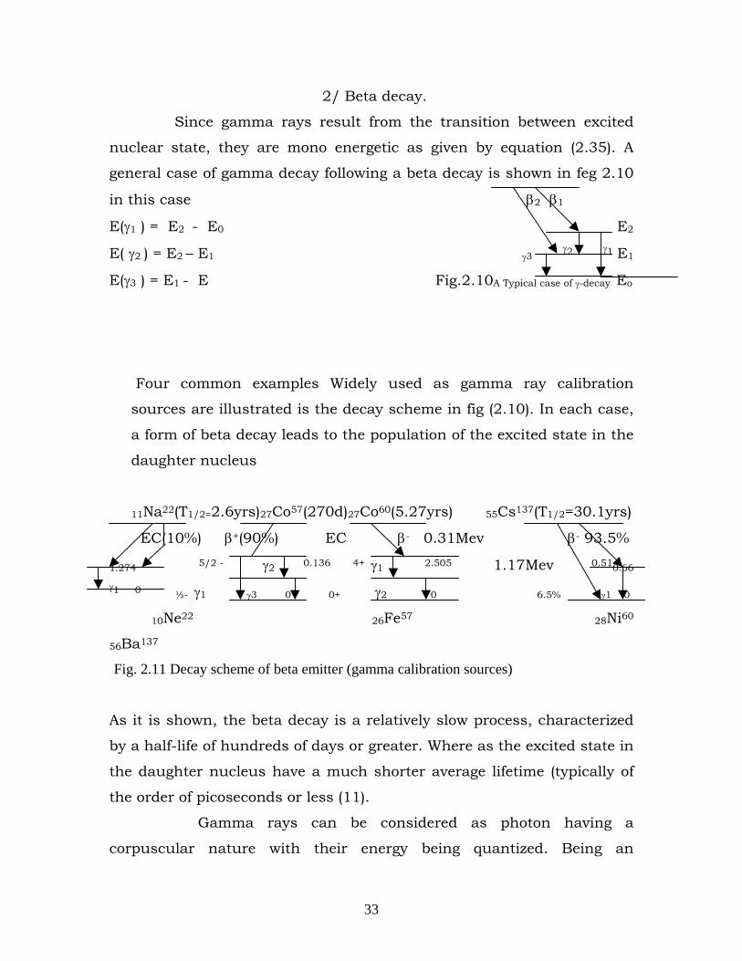
2/ Beta decay.
Since gamma rays result from the transition between excited
nuclear state, they are mono energetic as given by equation (2.35). A
general case of gamma decay following a beta decay is shown in feg 2.10
in this case β2 β1
E(γ1 ) = E2 - E0 E2
E( γ2 ) = E2 – E1 γ3 γ2 γ1 E1
E(γ3 ) = E1 - E Fig.2.10A Typical case of γ-decay Eo
Four common examples Widely used as gamma ray calibration
sources are illustrated is the decay scheme in fig (2.10). In each case,
a form of beta decay leads to the population of the excited state in the
daughter nucleus
11Na22(T1/2=2.6yrs)27Co57(270d)27Co60(5.27yrs) 55Cs137(T1/2=30.1yrs)
EC(10%) β+(90%) EC β- 0.31Mev β- 93.5%
1.274 5/2 - γ2 0.136 4+ γ1 2.505 1.17Mev 0.510.66 γ1 0 ½- γ1 γ3 0 0+ γ2 0 6.5% γ1 0
10Ne22 26Fe57 28Ni60
56Ba137
Fig. 2.11 Decay scheme of beta emitter (gamma calibration sources)
As it is shown, the beta decay is a relatively slow process, characterized
by a half-life of hundreds of days or greater. Where as the excited state in
the daughter nucleus have a much shorter average lifetime (typically of
the order of picoseconds or less (11).
Gamma rays can be considered as photon having a
corpuscular nature with their energy being quantized. Being an
34
electromagnetic radiation, it travels with the velocity of light. Thus a γ-
ray having a wave frequency v will have a quantum of energy hv. (where
h is Planck’s constant=6.626×1034 Js = 4.134x 10⁻¹⁵ evs). The energy of
gamma photon is determined by the difference in energy between
intermediate and final state of the nucleus (undergoing isomeric
transition). This difference is the same for all nuclei of a specific nuclide
have more than one intermediate state or energy level. When this is the
case, a radionuclide might emit gamma photons with several different
energies. If gamma ray comes out as a result of transition from an initial
nuclear state of energy. Ei to a final state of energy Ef. Then the energy of
γ-ray is given by: hv = Ei –Ef (2.35)
(3) Isomeric Transition (IT):
Nuclides having excited levels which do not decay instantaneously are
called isomeric nuclei. These levels are called Isomeric levels. They decay
either by γ-emission or by internal conversion. The transition leading to
the de excitation of such levels is called isomeric transition (IT).
Examples of decay scheme for nuclear isomers: Unlike other decays
these are isomeric level decays by γ-emission to the ground level, which
is stable.
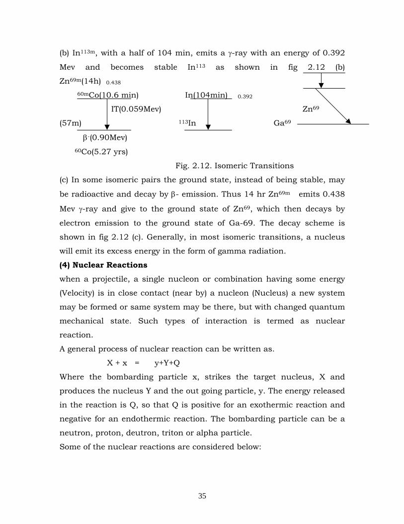
(a) The decay of 60mCo, by isomeric transition is shown in fig 2.12(a). The
half life of 60mCo isomeric level of 60Co, is 10.6Min. After a radioactive
nucleus undergoes an isobaric (A & Z unchanged) transition, it usually
contains too much energy to be in its final stable or daughter state.
When the excited level only decays by γ-emission to the ground level, as
in the case shown below, the members of the isomeric pair are said to be
genetically related.
35
(b) In113m, with a half of 104 min, emits a γ-ray with an energy of 0.392
Mev and becomes stable In113 as shown in fig 2.12 (b)
Zn69m(14h) 0.438
60mCo(10.6 min) In(104min) 0.392
IT(0.059Mev) Zn69
(57m) 113In Ga69
β-(0.90Mev)
60Co(5.27 yrs)
Fig. 2.12. Isomeric Transitions
(c) In some isomeric pairs the ground state, instead of being stable, may
be radioactive and decay by β- emission. Thus 14 hr Zn69m emits 0.438
Mev γ-ray and give to the ground state of Zn69, which then decays by
electron emission to the ground state of Ga-69. The decay scheme is
shown in fig 2.12 (c). Generally, in most isomeric transitions, a nucleus
will emit its excess energy in the form of gamma radiation.
(4) Nuclear Reactions
when a projectile, a single nucleon or combination having some energy
(Velocity) is in close contact (near by) a nucleon (Nucleus) a new system
may be formed or same system may be there, but with changed quantum
mechanical state. Such types of interaction is termed as nuclear
reaction.
A general process of nuclear reaction can be written as.
X + x = y+Y+Q
Where the bombarding particle x, strikes the target nucleus, X and
produces the nucleus Y and the out going particle, y. The energy released
in the reaction is Q, so that Q is positive for an exothermic reaction and
negative for an endothermic reaction. The bombarding particle can be a
neutron, proton, deutron, triton or alpha particle.
Some of the nuclear reactions are considered below:
36
(a) The possible, natural dcay processes, can be brought into the class
of reaction process with the conditions of no incoming particle x,
and Q>o. They are
(i) α-decay: ZXA Z-2YA-4 + 2He4
(ii) β-decay: ZXA Z+1YA + e- + ve (β- decay)
ZXA Z-1YA + e+ + ve ( β+-decay)
ZXA Z-1YA + ve (electron capture)
(iii) γ-decay:ZXA* ZXA + γ
(b) Elastic scattering: this is represented by: x+X x+X
Here the out going particle and the target nucleus remain the same
after interaction.
Ex. 2He4 + 79Au197 79Au179 + 2He4
Note there is no appreciable energy loss of the energy of the projectile.
(c) In elastic scattering (Collision):
x+X X* + x/
The resultant nucleus X is the same, but now is excited state. But
this remains only for sometime so that it decays to the ground state
by γ-ray emission.
i.e. X* X + γ
Ex :H + 3Li7 3 3Li7* + :H
(d) Radiative capture: x+x y* y + γ (representation)
In this case the target nucleus captures the projectile so that a new
system y is formed and it in excited state a gamma ray will be emitted.
This two common case of such reactions are (p,γ) and (n,γ) reaction.
(1) (p,γ) reaction: Here the bombarding proton is captured by the
nucleus. The compound nucleus, which is formed, is unstable,
and goes down to the ground state by emitting γ-ray protons. The
reaction is of the type
37
Z XA + 1H1 (ZYA+1)* Z+1YA+1 + γ
Some examples of (p,γ) reactions are:
3Li7 + 1H1 (4Be8)* 4Be8 +γ
6 C12 + 1H1 (7N13) * 7 N13 +γ
7 N14 + 1H1 (8 O15)* 8O15 + γ
12Mg24 + 1H1 (13Al25)* 13Al25 + γ
13Al27 + 1H1 (14Si28)* 14Si28 + γ
(iii) (n, γ) reaction. The other case of radiative capture is (n, γ)
reaction. In this case the target nucleus captures neutron and
the compound nucleus is formed in excited state. The reaction
can be represented by.
ZXA + 0n1 (ZXA+1) * ZXA+1 + γ
The simplest example fir (n,r) reaction is the reaction of hydrogen as a target with slow neutrons 1H1 + 0n1 (1H2)* 1H2 + γ Other examples of (n, γ) reaction are:
13Al27 + 0n1 13Al28)* 13Al28 + γ
29Cu63+ 0n1 29Cu64)* 29Cu64 + γ
47Ag107 + 0n1 (47Ag180)* 47Ag108 + γ
49In115 + 0n1 ( 49In116)* 49In116 + γ
Therefore we can see there are nuclear reactions in which γ-ray photons
are emitted. i.e. radiative capture, inelastic scattering and γ-decay.
Chapter Three- Interaction of nuclear radiation with Matter
3.1. Introduction
Nuclear radiations (alpha, beta, proton, neutron, gamma ray, etc) are
emitted as a result of various transformations and adjustments that take
place inside the nucleus. Any radiation is detected by its interaction with
matter. If this interaction is very small as in the case of neutron, the
detection of radiation becomes extremely difficult. It is necessary to study
38
the manner in which nuclear radiation interact with matter in order to
understand the methods and instruments used for the detection,
measurement and characterization of nuclear radiation. (13) We shall
confine our discussion to incident energy of the order 0.1-5Mev. For
these energies, coulomb force are mainly responsible for these
interactions (we shall not deal with those interactions which arise from
specifically nuclear force) & they give rise to ionization, scattering and
radiative loses. (9)
The harmful effects of the radiations on tissues are highly dependent on
the ability of the radiations to ionize the matter. Further, the selection of
proper shielding material for the safe handling of radiation substance is
based on our knowledge of the penetration of nuclear radiation in matter.
Nuclear radiation can be classified in the following groups.
(1) Charged radiation a) Heavy charged particles (alpha, proton,
deutron etc)
b) light charged particles (mainly electron).
(2) Uncharged radiation a) Electro magnitude radiation gamma
rays
b) Neutral particles (Mainly neutron)
The passage through matter of charged particle, (mainly electron) and
uncharged radiation (mainly gamma radiation) will be treared in the next
section.
3.2. Interaction of Heavy charged particles
(i) Nature of the interaction
Heavy charged particles such as the alpha particle interact with matter
primarily through coulomb’s force between their positive charge and the
negative charge of the orbital electron, within the absorber atoms.
Although interactions of the particle with nucleus are also possible, such
encounters occur only rarely and they are not normally significant in the
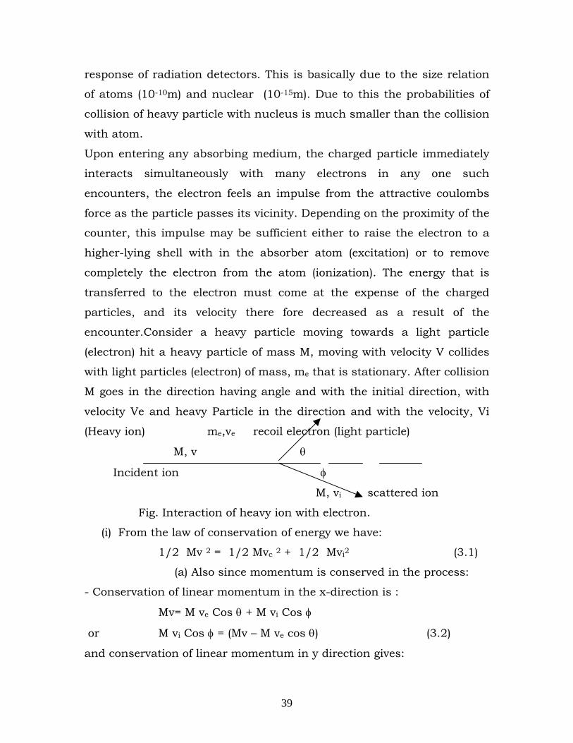
39
response of radiation detectors. This is basically due to the size relation
of atoms (10-10m) and nuclear (10-15m). Due to this the probabilities of
collision of heavy particle with nucleus is much smaller than the collision
with atom.
Upon entering any absorbing medium, the charged particle immediately
interacts simultaneously with many electrons in any one such
encounters, the electron feels an impulse from the attractive coulombs
force as the particle passes its vicinity. Depending on the proximity of the
counter, this impulse may be sufficient either to raise the electron to a
higher-lying shell with in the absorber atom (excitation) or to remove
completely the electron from the atom (ionization). The energy that is
transferred to the electron must come at the expense of the charged
particles, and its velocity there fore decreased as a result of the
encounter.Consider a heavy particle moving towards a light particle
(electron) hit a heavy particle of mass M, moving with velocity V collides
with light particles (electron) of mass, me that is stationary. After collision
M goes in the direction having angle and with the initial direction, with
velocity Ve and heavy Particle in the direction and with the velocity, Vi
(Heavy ion) me,ve recoil electron (light particle)
M, v θ
Incident ion φ
M, vi scattered ion
Fig. Interaction of heavy ion with electron.
(i) From the law of conservation of energy we have:
1/2 Mv 2 = 1/2 Mvc 2 + 1/2 Mvi2 (3.1)
(a) Also since momentum is conserved in the process:
- Conservation of linear momentum in the x-direction is :
Mv= M ve Cos θ + M vi Cos φ
or M vi Cos φ = (Mv – M ve cos θ) (3.2)
and conservation of linear momentum in y direction gives:
40
O = M vi sin φ - M ve sin θ
or M vi sin 4 = M ve sin θ (3. 3)
But since we are intersected in the direction, θ, to eliminate φ, squaring
and adding questions (3.2) and (3.3)
M2 vi 2 = (Mv – M ve cos θ) 2 + m2 ve 2 sin 2 θ
M2 Vi2 = M2 V2 + M2 ve 2 – 2Mm v ve cos θ, dividing by M2 we get
Vi2 = V2 + (m/M)2 + Ve 2 – 2 m/M V Ve Cos θ (3. 4)
From equation (1), Vi2 = V2 – me/M Ve2 (3. 5)
Now equating equations (3.4) and (3.5): we have:
Ve (1+ me/M) = 2v cos θ
or Ve = )/1(
cos2Mm
v
e+θ (3. 6)
We are intersected in the maximum value of Ve, and hence taking, θ =o
(recoil in forward direction) and M>>m,
(Ve) Max = 2v (3.7)
This shows that the maximum energy that can be transferred from a
charged particle of mass M with kinetic energy E to an electron of mass
me in a single collision is
4Emo/m, (or about 1/500 of the particle energy per nucleon)
(½ me Ve2 = ½ (me 4 v2) = 4 me/M) E.
Because this is a small fraction the total energy, the primary particle
must lose its energy in many such interactions during its passage
through an absorber. At any given time, the particle is interacting with
many electrons, so the net effect is to decrease its velocity continuously
until the particle is stopped. Therefore charged particles are
characterized by a definite range in a given absorber material, distance
beyond which no particles will penetrate.
41
(2) Stopping power
The linear stopping power for charged particle in a given absorber is
simply defined as the differential energy loss for that particle with in the
material divided by the corresponding differential path length.
S = dxdE
− (3.8)
The value ofdxdE
− along a particle track is also called its specific energy
loss or, more casually, its rate of energy loss.[11].
If the incident particle has mass M and energy E and collides with an
electron of mass me, then the maximum energy, which the electron can
acquire, is:
(Te)Max = 1/2 me (Ve)2 Max = 1/2me [ Mv / (me + M) ] 2
or (Te) Max = (4m M/(m +M) 2) E (3.9)
or approximately (Te) max = 4 mE/M, When M>>m as derived above (eq.
6). For light particle of several Mev this energy is of the order 10Kev so
that it is justifiable to neglect the electronic binding energy and consider
the collisions to occur with free electrons. The more energetic recoiling
electrons resulting from such collisions are often called ‘delta rays’. Since
their appearance in early cloud chamber experiments led to the mistaken
idea that they were a fourth type of radiation.
The transfer of energy at each collision is thus generally a small fraction,
of the order 10-3 times the particle energy, so that the deflections from a
straight line path are small. The range, determined by a large number of
events, is well defined. Calculation of the energy loss per unit path length
have been made by livingston and Bethe with a result expressed by:
dxdE
− = Bmv
ZNze2
244π− 3.(10)
42
Where e & m are electronic charge and mass, ze and v are the particle
charge and velocity, Z in the atomic number of the absorber and N the
number of absorber atoms per Cm3. B, sometimes called the stopping
number, is the logarithmic function.
B= Log e (2nv 2/I) – Log e (1-v2/c2) – V2/C2) 3. (11)
Here I is the mean ionization potential of the absorber atoms and C is
the velocity of light. The first term in the expression predominates up to
1000 Mev. B therefore varies rather slowly with particle energy, and
approximately, from equation (3.10).
dxdE ∝ 2
2
vz ∝
Ez 2
(3.12)
This is to be expected since the slower the particle the greater is the time
for which its coulomb field acts upon the electron and the greater
impulse imparted gives an increased probability of excitation.
The range, R, of a particle is given by the integral
R = ∫E
dxdEdE
0 )/( =
NZzemM
244π ∫
v
vBdvv
0
3
)(
(3.13)
It is convenient to use this equation to relate the range of one particle to that of another of the same initial velocity. We may write R (V)= M/z2. f(v).
where f(v) involves only the particle velocity. Thus for the range of proton
and deuterons (Z=1) R(E) = dd
RMM ( E
MM d × ) 3.(14)
R(E) = 0.50 Rd (2.0E)
For particles of different z there is a small correction term, c, owing to the
different rate of capture and loss near the end of the range. Thus, for
proton and alphas,
Rp(E) = 1.007 Rd (3.972 E) – C
Where C = 0.2 Cm in air, and microns in silicon.
43
3.3. Interaction of light charged particles with matter
3.3.1. Electrons
Beta rays are fast electrons, which may be emitted, in natural
radioactivity of induced activity following nuclear transmutation that is
caused by another nuclear radiation. They may also be produced by the
acceleration in an electric field of electrons emitted from a heated
filament. Electrons differ from heavy particles in that their paths in
solids are not straight and their ranges is therefore rather indefinite. This
is because their mass is the same as that of the electron in the absorber
so that as much as half the initial energy may be lost in a single
collision. The deflections and the statistical straggling in range are
therefore large, as has been revealed by cloud chamber experiments in
which the track of a single electron can be made visible. The high
velocities often attained by electron, quite commonly an appreciable
fraction of the velocity of light, makes it necessary to describe their
motion relativistically. Following are the four important processes by
which electrons lose their kinetic energy during their passage through
matter.
(i) In-elastic collision of electrons: In-elastic collision of incident electrons
with bound atomic electrons in the matter is the most important
mechanism by which incident electron loses their energy in their passage
through matter. During such in-elastic collision, incident electron
transfers part of its energy to a bound atomic electron taking it to an
excited state (excitation) or an unbound state (ionization).
For electrons of up to 10 Mev the dominant mode of energy loss are
excitation and ionization of the electron of the absorber, just as in the
case of heavy particles. The rate of energy loss is therefore given by the
same formula, with z=1.
. dxdE
− = Bmv
ZNze2
244π− 3. (15)
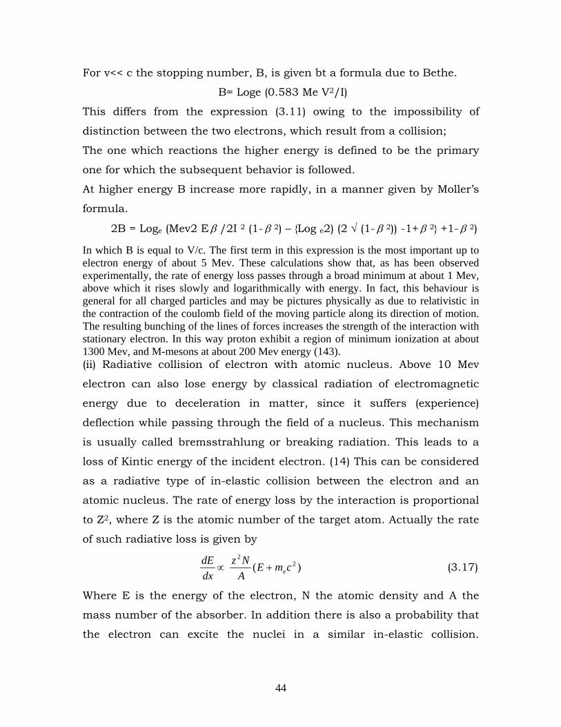
44
For v<< c the stopping number, B, is given bt a formula due to Bethe.
B= Loge (0.583 Me V2/I)
This differs from the expression (3.11) owing to the impossibility of
distinction between the two electrons, which result from a collision;
The one which reactions the higher energy is defined to be the primary
one for which the subsequent behavior is followed.
At higher energy B increase more rapidly, in a manner given by Moller’s
formula.
2B = Loge (Mev2 E β /2I 2 (1- β 2) – {Log e2) (2 √ (1- β 2)) -1+ β 2} +1- β 2)
In which B is equal to V/c. The first term in this expression is the most important up to electron energy of about 5 Mev. These calculations show that, as has been observed experimentally, the rate of energy loss passes through a broad minimum at about 1 Mev, above which it rises slowly and logarithmically with energy. In fact, this behaviour is general for all charged particles and may be pictures physically as due to relativistic in the contraction of the coulomb field of the moving particle along its direction of motion. The resulting bunching of the lines of forces increases the strength of the interaction with stationary electron. In this way proton exhibit a region of minimum ionization at about 1300 Mev, and M-mesons at about 200 Mev energy (143). (ii) Radiative collision of electron with atomic nucleus. Above 10 Mev
electron can also lose energy by classical radiation of electromagnetic
energy due to deceleration in matter, since it suffers (experience)
deflection while passing through the field of a nucleus. This mechanism
is usually called bremsstrahlung or breaking radiation. This leads to a
loss of Kintic energy of the incident electron. (14) This can be considered
as a radiative type of in-elastic collision between the electron and an
atomic nucleus. The rate of energy loss by the interaction is proportional
to Z2, where Z is the atomic number of the target atom. Actually the rate
of such radiative loss is given by
dxdE
∝ )( 22
cmEANz
e+ (3.17)
Where E is the energy of the electron, N the atomic density and A the
mass number of the absorber. In addition there is also a probability that
the electron can excite the nuclei in a similar in-elastic collision.
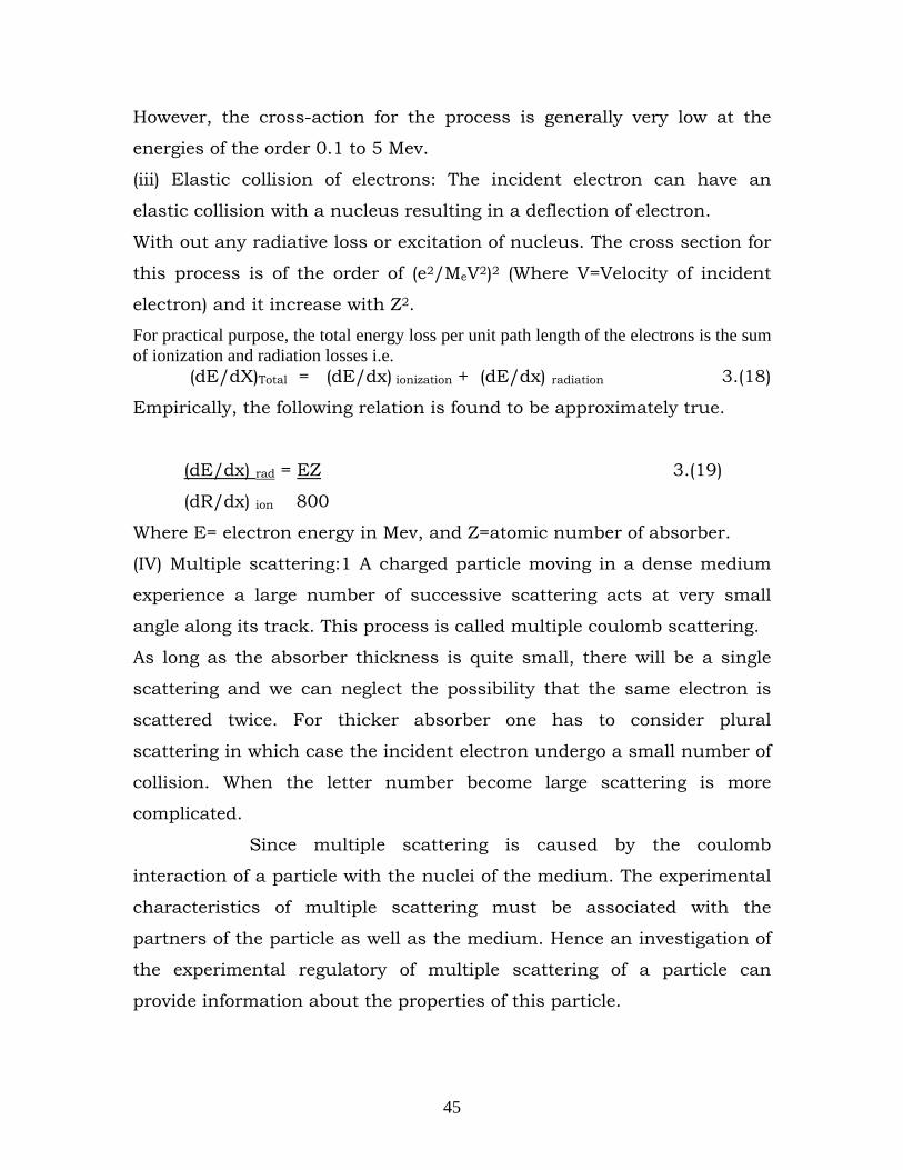
45
However, the cross-action for the process is generally very low at the
energies of the order 0.1 to 5 Mev.
(iii) Elastic collision of electrons: The incident electron can have an
elastic collision with a nucleus resulting in a deflection of electron.
With out any radiative loss or excitation of nucleus. The cross section for
this process is of the order of (e2/MeV2)2 (Where V=Velocity of incident
electron) and it increase with Z2.
For practical purpose, the total energy loss per unit path length of the electrons is the sum of ionization and radiation losses i.e. (dE/dX)Total = (dE/dx) ionization + (dE/dx) radiation 3.(18)
Empirically, the following relation is found to be approximately true.
(dE/dx) rad = EZ 3.(19)
(dR/dx) ion 800
Where E= electron energy in Mev, and Z=atomic number of absorber.
(IV) Multiple scattering:1 A charged particle moving in a dense medium
experience a large number of successive scattering acts at very small
angle along its track. This process is called multiple coulomb scattering.
As long as the absorber thickness is quite small, there will be a single
scattering and we can neglect the possibility that the same electron is
scattered twice. For thicker absorber one has to consider plural
scattering in which case the incident electron undergo a small number of
collision. When the letter number become large scattering is more
complicated.
Since multiple scattering is caused by the coulomb
interaction of a particle with the nuclei of the medium. The experimental
characteristics of multiple scattering must be associated with the
partners of the particle as well as the medium. Hence an investigation of
the experimental regulatory of multiple scattering of a particle can
provide information about the properties of this particle.
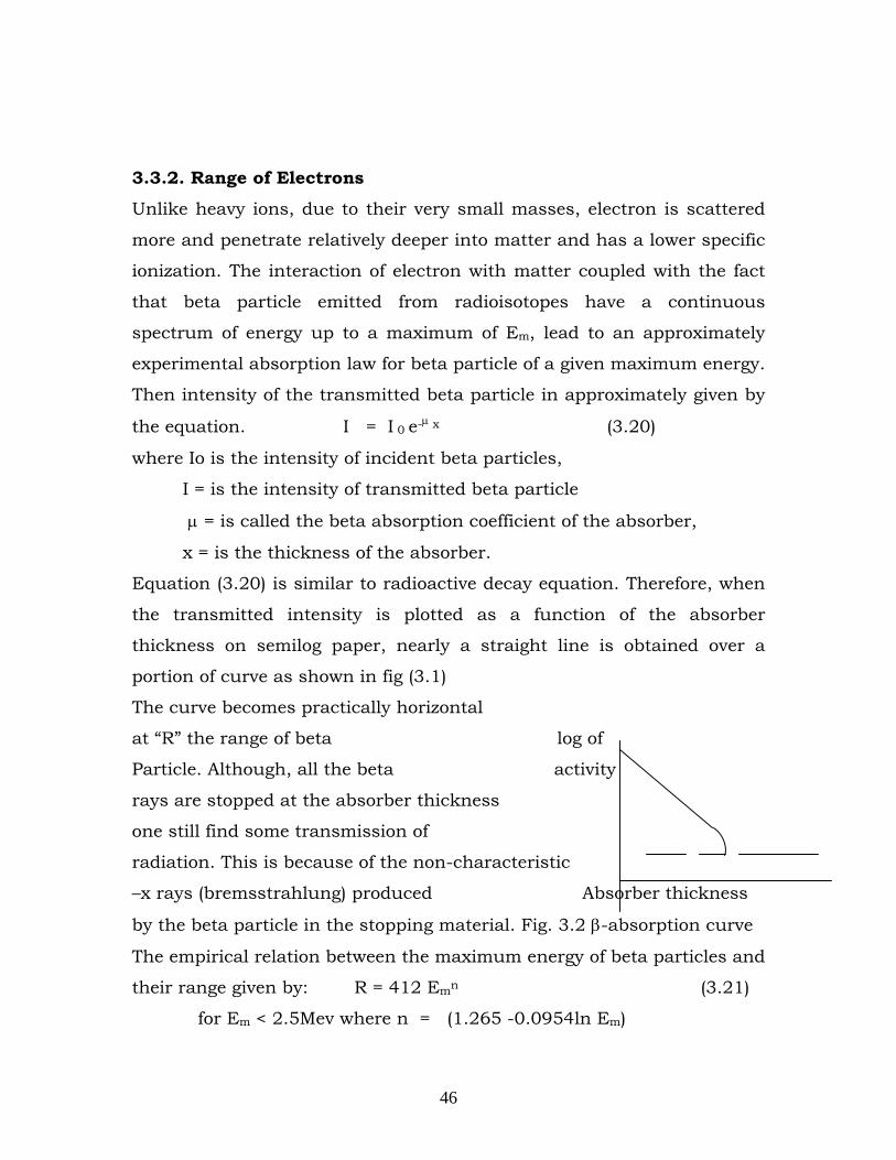
46
3.3.2. Range of Electrons
Unlike heavy ions, due to their very small masses, electron is scattered
more and penetrate relatively deeper into matter and has a lower specific
ionization. The interaction of electron with matter coupled with the fact
that beta particle emitted from radioisotopes have a continuous
spectrum of energy up to a maximum of Em, lead to an approximately
experimental absorption law for beta particle of a given maximum energy.
Then intensity of the transmitted beta particle in approximately given by
the equation. I = I 0 e-μ x (3.20)
where Io is the intensity of incident beta particles,
I = is the intensity of transmitted beta particle
μ = is called the beta absorption coefficient of the absorber,
x = is the thickness of the absorber.
Equation (3.20) is similar to radioactive decay equation. Therefore, when
the transmitted intensity is plotted as a function of the absorber
thickness on semilog paper, nearly a straight line is obtained over a
portion of curve as shown in fig (3.1)
The curve becomes practically horizontal
at “R” the range of beta log of
Particle. Although, all the beta activity
rays are stopped at the absorber thickness
one still find some transmission of
radiation. This is because of the non-characteristic
–x rays (bremsstrahlung) produced Absorber thickness
by the beta particle in the stopping material. Fig. 3.2 β-absorption curve
The empirical relation between the maximum energy of beta particles and
their range given by: R = 412 Emn (3.21)
for Em < 2.5Mev where n = (1.265 -0.0954ln Em)
47
and R=530 Em -106 (3.22)
for Em >2.5 MevWhere the unit of range R is (mg/cm3) while that for Em
is (Mev)
3.3.2. Positrons
The interaction of positrons with matter is almost identical with that of electron but for
some minor differences. However, there is a very important way in which positrons can
annihilate with the electrons in matter. This annihilation can either be a free annihilation
with an electron or via the formation of a (e+ e-) hydrogen-like atom called positron. The
positron annihilation leads to 2 photons if the electron-positron spin is anti parallel and
into 3 photons if the spin orientation is parallel.
3.4 INTERACTION OF GAMMA RAY WITH MATTER
Gamma rays interact with matterby one of the three typpes of process, namely the
photoelectric effect, compton scattering and pair production.
(i) in photoelectric effect the photon of energy Eγ with a whole atomof the
absorber, and the whole energy is used to eject an electron, usually from one of the inner
electron orbits, and E β = Eγ - Eb (3.23)a
Where Eb is the binding energy of the electron. the original gamma ray disappears
in this process, but the excited atom will subsequently emit one or more x-rays of total
energy Eb
(ii) the compton scattering processmay be considered as an elastic collission
between a photon and an electron , in which the electron binding energy is very small
compared with the photon energy. The energy is shared between the scattered photon
and the recoilking electron.
(iii) In pair production the photon dis appears and an electron positron pair is
created with total kinetic energy kinetic energy equal to the photon energy less the rest
energy of the two particles.
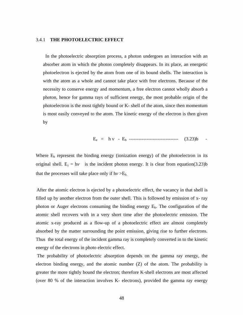
48
3.4.1 THE PHOTOELECTRIC EFFECT
In the photoelectric absorption process, a photon undergoes an interaction with an
absorber atom in which the photon completely disappears. In its place, an energetic
photoelectron is ejected by the atom from one of its bound shells. The interaction is
with the atom as a whole and cannot take place with free electrons. Because of the
necessity to conserve energy and momentum, a free electron cannot wholly absorb a
photon, hence for gamma rays of sufficient energy, the most probable origin of the
photoelectron is the most tightly bound or K- shell of the atom, since then momentum
is most easily conveyed to the atom. The kinetic energy of the electron is then given
by
Ee = h ν - Eb ------------------------------- (3.23)b -
Where Eb represent the binding energy (ionization energy) of the photoelectron in its
original shell. Eγ = hv is the incident photon energy. It is clear from equation(3.23)b
that the processes will take place only if hv >Eb.
After the atomic electron is ejected by a photoelectric effect, the vacancy in that shell is
filled up by another electron from the outer shell. This is followed by emission of x- ray
photon or Auger electrons consuming the binding energy Eb. The configuration of the
atomic shell recovers with in a very short time after the photoelectric emission. The
atomic x-ray produced as a flow-up of a photoelectric effect are almost completely
absorbed by the matter surrounding the point emission, giving rise to further electrons.
Thus the total energy of the incident gamma ray is completely converted in to the kinetic
energy of the electrons in photo electric effect.
The probability of photoelectric absorption depends on the gamma ray energy, the
electron binding energy, and the atomic number (Z) of the atom. The probability is
greater the more tightly bound the electron; therefore K-shell electrons are most affected
(over 80 % of the interaction involves K- electrons), provided the gamma ray energy
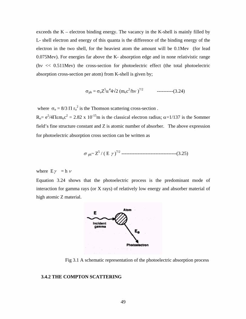
49
exceeds the K – electron binding energy. The vacancy in the K-shell is mainly filled by
L- shell electron and energy of this quanta is the difference of the binding energy of the
electron in the two shell, for the heaviest atom the amount will be 0.1Mev (for lead
0.075Mev). For energies far above the K- absorption edge and in none relativistic range
(hν << 0.511Mev) the cross-section for photoelectric effect (the total photoelectric
absorption cross-section per atom) from K-shell is given by;
σph = σeZ5α44√2 (moc2/hν )7/2 ----------(3.24)
where σe = 8/3 Π ro2 is the Thomson scattering cross-section .
Ro= e2/4Πεmoc2 = 2.82 x 10⁻¹⁵m is the classical electron radius; α=1/137 is the Sommer
field’s fine structure constant and Z is atomic number of absorber. The above expression
for photoelectric absorption cross section can be written as
σ ph~ Z5 / ( E γ )7/2 ----------------------------------(3.25)
where Eγ = h ν
Equation 3.24 shows that the photoelectric process is the predominant mode of
interaction for gamma rays (or X rays) of relatively low energy and absorber material of
high atomic Z material.
Fig 3.1 A schematic representation of the photoelectric absorption process
3.4.2 THE COMPTON SCATTERING
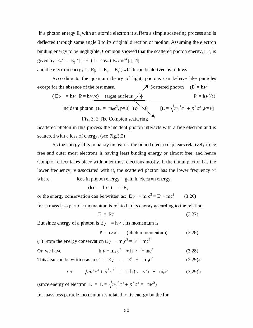
50
If a photon energy Eγ with an atomic electron it suffers a simple scattering process and is
deflected through some angle θ to its original direction of motion. Assuming the electron
binding energy to be negligible, Compton showed that the scattered photon energy, Eγ’, is
given by: Eγ’ = Eγ / [1 + (1 – cosφ) Eγ /mc2]. [14]
and the electron energy is: Eβ = Eγ - Eγ’, which can be derived as follows.
According to the quantum theory of light, photons can behave like particles
except for the absence of the rest mass. Scattered photon (E/ = hν /
( Eγ = hν , P = hν /c) target nucleus φ P/ = hν //c)
Incident photon (E = m0c2, p=0) ) φ θ [E = 2420
2
cpcm + ,P=P]
Fig. 3. 2 The Compton scattering
Scattered photon in this process the incident photon interacts with a free electron and is
scattered with a loss of energy. (see Fig.3.2)
As the energy of gamma ray increases, the bound electron appears relatively to be
free and outer most electrons is having least binding energy or almost free, and hence
Compton effect takes place with outer most electrons mostly. If the initial photon has the
lower frequency, v associated with it, the scattered photon has the lower frequency v/,
where: loss in photon energy = gain in electron energy
(hν - hν /) = Ee
or the energy conservation can be written as: Eγ + moc2 = E/ + mc2 (3.26)
for a mass less particle momentum is related to its energy according to the relation
E = Pc (3.27)
But since energy of a photon is Eγ = hν , its momentum is
P = hν /c (photon momentum) (3.28)
(1) From the energy conservation Eγ + moc2 = E/ + mc2
Or we have h ν + mo c2 + h ν /+ mc2 (3.28)
This also can be written as mc2 = Eγ - E/ + moc2 (3.29)a
Or 2420
2
cpcm + = = h ( vv − /) + moc2 (3.29)b
(since energy of electron E = E = 2420
2
cpcm + = mc2)
for mass less particle momentum is related to its energy by the for
51
E = Pc and for the photon Eγ = hν , its momentum is, P = hν /c
(2) for the above process the conservation of momentum gives:
(i) for the x- direction: h v /c = hv / /c cosΦ + pcosθ (3.30)
(ii) for the y- direction; 0 =( h v / /c) sin φ - p sin θ (3.31)
(where m = 2
2
0 1cvm − is the relativistic mass of the recoil electron where
C = 2.988 x 10⁻⁸ m/s is the speed of light and h = 6.66 x 10⁻³⁴Js is the planck’s constant
v and v / are frequency of incident gamma ray and scattered gamma ray respectively)
To eliminate θ we can write the above equations as follows:
Squaring and adding equations 3.30 and 3.31 we obtain:
P2c2 = ( h v /c)2 + ( hv / /c)2 - 2 h v /c( hv / /c) cosΦ (3.32)
Also squaring and adding equations 3.29a and 3.29b, we have:
P2c2 + (moc2)2 = (h v - hv /)2 +2 moc2 ( h v - hv /) + mo2c4
P2c2 = (h v )2 + ( hv /)2 - 2 h v ( hv /) + 2 moc2 ( h v - hv /) (3.33)
Finally equating equations 3.32 and 3.33 we obtain:
2 moc2 ( h v - hv /) - 2 h v ( hv /) = - 2 h v ( hv /) cosΦ
or 2 moc2 ( h v - hv /) = 2 h v ( hv /)(1 - cosΦ )
this can be written in a convenient form as
( v - ν/) / v ν/ = [h/moc2 ] (1 - cosΦ ) (3.34)a
(1 / v - 1 / ν/ ) = h/moc2 (1 – cosΦ) (3.35)b
This relationship is simpler when expressed in terms of wave length rather than
frequency. From c = λ v , substituting 1 / v = λ /c into equation 3.35b, we get:
(λ/ /c - λ /c) = h/moc2 (1 – cosΦ) (3.36)a
(λ/ - λ) = h/moc (1 – cosΦ) (3.37)b
or Δλ = h/moc (1 – cosΦ)
52
where λ is wave length of primary gamma ray photon, λ / is wave length of scattered
gamma ray photon and λλ − / is the change in wavelength of Compton scattered
gamma ray or Compton shift This equation (3.37) b was derived by Arthur H Compton in
the early 1920s, and the phenomenon which it describes, which he was first to observe is
known as the Compton effect
h /moc =0.0242 Ao is called Compton wavelength.
The wave length shift or Compton shift λ / - λ , thus depends on the angle of scattering
angle φ and can be written as;
∆ λ = 0.0242 (1-cosφ ) (3.38)
where λ is measured in angstroms (Ao) . It does not depend on the scattering material (Z)
and energy of incident gamma ray. From this relation we see that, (i) For φ = 0, Δλ = 0
and no Compton effect. This is the case for low incident gamma ray energy (h v << moc2)
(ii) For φ = 90o, Δλ = h / moc = 0.0242A and
(iii) For φ = 180, Δλ = 2 h / moc = 0.0484 Ao, corresponds to maximum change in back
scattered gamma ray, which means that the change in wave length of gamma radiation
interacting with electron never exceed 0.0484Ao. Energy of scattered photon is minimum
but never zero, so that complete absorption is not possible. Compton effect is the process
of partial scattering and partial absorption as a part of the energy is transferred to an
electron.
(2) In Compton process the dependence of both kinetic energy of recoiling electron and
energy of scattered gamma ray on the scattering angle (φ) and energy of incident gamma
ray can be found follows: From equation 3.35b
1 / v / = 1 / ν = h/moc2(1 – cosΦ)
i.e. 1 /ν/ = [1 + h v /moc2 (1 – cosΦ)] / v
or ν/ = v / [1 + h v /moc2 (1 – cosΦ)] (3.39)
Then introducing this result, the energy of the scattered photon (kinetic energy) which is
given by E/ = hν /, becomes: E/ = hν / = h v / [1 + ( h v /moc2 ) (1 – cosΦ)] (3.40)
This also gives the minimum energy of photon to be,
E/min
= h v / [1 + 2h v /moc2 ] (3.41)
= moc2/2 = 255.5Kev ; if hν >> moc2/2 .
53
(3) Then the kinetic energy of the recoiling electron, introducing the result from part 2
can be expressed as: : Eβ = Eγ - Eγ / = h v - h v / [1 + h v /moc2 (1 – cosΦ)]
or Eβ = [ h v / moc2 (1 – cosΦ)] h v / [1 + h v /moc2 (1 – cosΦ)]
This result shows that `the recoil electrons may have any energy between zero and a
maximum corresponding to a minimum value of Eγ /, which occurs for a back scattered
photon(φ = 180o). Then or (Eβ)max = [2(h v )2 /moc2] / (1 + 2(h v ) /moc2
or (Eβ)max = 2 (Eγ )2 / (moc2 + 2 Eγ ) (3.42)a
or = hν /[1+ moc2/2hν ] (3.42)b
The relation between the angle θ at which the recoil electron leaves
and the angle φ at which the scattered gamma ray leaves can be easily obtained by taking
the ratio of equation 330 and 3.31 together with the trigonometric identity, is given by;
Cotθ = (1+hν /moc2) tan(φ/2) (3.43)
Where tanφ/2 =(1-cosφ)/sinφ
From this relation (3.43), as the gamma ray scattered in the range, from φ = 0 to φ =180;
the recoiling electrons can emitted in the range from θ =90 to 0. For backward scattered
gamma ray
(φ =180 ) , the electron scattered forward (θ =0) .For these cases the energy of scattered
gamma ray which is minimum , given by equation 3.41 and energy of the scattered
electron ,which is maximum , given by equation (3.42). Every electron in the absorber
can contribute independently to this process, so that the Compton absorption coefficient
is proportional to the electron density NZ. Klein and Nishina showed that at high energies
(Eγ > 1Mev) the absorpt6ion coefficient is given by
μcompton ≈ 1.25 x 10⁻²⁵ (NZ / Eγ )[loge(2Eγ /mc2) + 1/2] cm-1 (3.44)
which approximates to an inverse dependence on Eγ
Also the Compton scattering cross sections have been theoretically calculated by the
Klein and Nishina From this formula for energy photon (α <<1) the scattering cross
section per electron is given by:
eσ c = σ e ( 1- 2 α + 26/5 α 2 --------- ) (3.45)
54
where α = hν / moc2 and σ e = 8/3 π ( e2/ moc2 )2 = 6.651 x10⁻²⁸ m2 is Thomson cross
section and for high energy photon ( α > 1 ) the scattering cross section per electron is
given by
eσ c = α
ασ 2/1)2ln(3/8 +C (3.46)
The above asymptotic expression for σ c shows that at low energy eσ c decreases with
increasing photon energy, and at high energy it falls off more rapidly with increasing
photon energy. In Compton process the assumed electrons are free. For photon energies
of well above the binding energies it assumes that all atomic electrons are available for
the process, and Compton cross section per atom is given by
σ c = Z e σ c (3.47)
where Z is atomic number of scatter;
2.1.3 Pair production
Pair production is the third mechanism by which gamma ray interact with matter with the
production of an electron- positron pair (γ → e- +e+). For pair production to occur the
gamma ray energy must exceed the rest energy of the electron and positron, i.e. 1.02
Mev. In order that the momentum and mass energy may both be conserved; the process
can take place only in the field of the third particle. This is generally an atomic nucleus,
although the effect can occur in the field of an electron. The excess energy appears as
kinetic energy, Ekin, of the electron positron pair, and a very small recoil energy is
imparted to the nucleus.
Ekin = Eγ - 1.02 Mev (3.48)
At energies near the threshold, the absorption coefficient depends linearly upon the
photon energy the absorption coefficient depends linearly upon the photon energy.
μpair ∝ NZ2(Eγ - 2mc2) (3.49)
while at higher energies the dependence becomes logarithmic.
μpair ∝ NZ2logeEγ
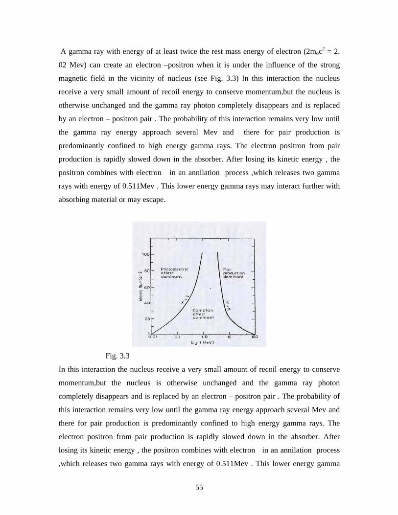
55
A gamma ray with energy of at least twice the rest mass energy of electron (2moc2 = 2.
02 Mev) can create an electron –positron when it is under the influence of the strong
magnetic field in the vicinity of nucleus (see Fig. 3.3) In this interaction the nucleus
receive a very small amount of recoil energy to conserve momentum,but the nucleus is
otherwise unchanged and the gamma ray photon completely disappears and is replaced
by an electron – positron pair . The probability of this interaction remains very low until
the gamma ray energy approach several Mev and there for pair production is
predominantly confined to high energy gamma rays. The electron positron from pair
production is rapidly slowed down in the absorber. After losing its kinetic energy , the
positron combines with electron in an annilation process ,which releases two gamma
rays with energy of 0.511Mev . This lower energy gamma rays may interact further with
absorbing material or may escape.
Fig. 3.3
In this interaction the nucleus receive a very small amount of recoil energy to conserve
momentum,but the nucleus is otherwise unchanged and the gamma ray photon
completely disappears and is replaced by an electron – positron pair . The probability of
this interaction remains very low until the gamma ray energy approach several Mev and
there for pair production is predominantly confined to high energy gamma rays. The
electron positron from pair production is rapidly slowed down in the absorber. After
losing its kinetic energy , the positron combines with electron in an annilation process
,which releases two gamma rays with energy of 0.511Mev . This lower energy gamma
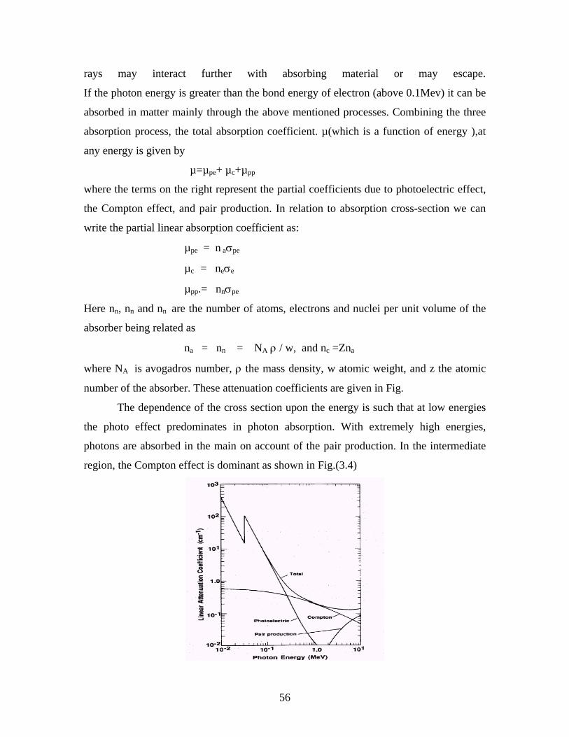
56
rays may interact further with absorbing material or may escape.
If the photon energy is greater than the bond energy of electron (above 0.1Mev) it can be
absorbed in matter mainly through the above mentioned processes. Combining the three
absorption process, the total absorption coefficient. µ(which is a function of energy ),at
any energy is given by
µ=µpe+ µc+µpp
where the terms on the right represent the partial coefficients due to photoelectric effect,
the Compton effect, and pair production. In relation to absorption cross-section we can
write the partial linear absorption coefficient as:
µpe = n aσpe
µc = neσe
µpp.= nnσpe
Here nn, nn and nn are the number of atoms, electrons and nuclei per unit volume of the
absorber being related as
na = nn = NA ρ / w, and nc =Zna
where NA is avogadros number, ρ the mass density, w atomic weight, and z the atomic
number of the absorber. These attenuation coefficients are given in Fig.
The dependence of the cross section upon the energy is such that at low energies
the photo effect predominates in photon absorption. With extremely high energies,
photons are absorbed in the main on account of the pair production. In the intermediate
region, the Compton effect is dominant as shown in Fig.(3.4)
57
Fig. 3.4 Attenuation coefficients of Gamma rays in sodium iodide.
CHAPTER FOUR
NUCLEAR RADIATION DETECTION AND MEASUREMENT
4.1 Introduction
A number of factors are common to different methods of detection of nuclear radiations.
In general detection methods are based on the processes of ionization and excitation of
atom in the detection medium by the passage of a charged particle. Neutral particles or
electromagnetic radiation must interact first with the detection medium or with an
adjoining converter in order to produce the charged particles required for ionization. The
methods by which the ions, electrons, or excited atoms are subsequently made apparent
vary widely and have been adapted to many different types of system, solid, liquid and
gaseous, either with or without an applied electric field.
In both gaseous and solid counters charged particles liberated by ionization can be
collected by ionization can be collected at boundary electrodes under an applied electric
field. In the other important types of solid state detector, the scintillation counter, use is
made of emission of light by excited atoms, detected by conversion of a stream of
electron from the photo sensitive cathode of a photo multiplier tube
Nuclear radiation detectors can be divided into two main groups:
(1) Electrical pulse detectors,
(2) Track detectors.
(1) In the electrical pulse detectors, a nuclear particles detected by the electrical pulse
generated by the particle in the detector and the mean level of radiation flux is
measured.[14] they give information about nuclear radiation quickly and easily.
(2) In the second type, the track (path) of the particle is recorded. Such detectors can give
more information about the nuclear radiation (particle) because one can see the actual
path of the nuclear particle and can have permanent record of this path (by photography),
which can be analyzed at any later time. Though they are slow and tedious, it is possible
to distinguish individual particles using track detectors.
58
Generally electrical pulse detectors are used for the measurement of activity from
radioisotopes. The counters that are commonly used to detect nuclear radiation by the
electrical pulse generated by radiation can be categorized as:
(1) Gas Filled detectors (counters)
(2) Scintillation counters (detectors)
(3) Semiconductor detectors
In this chapter first I will describe the last two detectors shortly and then discuss about
the gas filled detectors.
4.2 Detector Overview
Since we cannot see, smell or taste radiation, we are dependent on instruments to indicate
the presence of ionizing radiation. Most nuclear measurements involve the detection of
particles –particles ejected from the radioactive nuclei, particles produced from
accelerators probe nuclei, and particles created in nuclear reactions. In addition to
detecting these particles, one must usually measure some of their properties – their mass,
charge, energy momentum and so on. In the coarse of detecting and measuring particles,
there is a sharp distinction between charged and neutral particles. when a charged particle
passes through matter (solid liquid or gas) it can ionize or raise them to excited states.
This ionization or excitation is easily detected and is the basis for most detectors of
charged particles. Neutral particles, such as the photon (γ-ray) and neutron, are usually
not easily detected, and most detectors of neutral particles work by having the neutral
produce a charged particle and then detecting the charged particle.
(1) Gas Filled Detectors: the most common type of instrument is gas filled
detector. This instrument works on the principle that as radiation passes
through air or specific a gas, ionizing of the molecules in the air occur. When
a high voltage is placed between two areas of the gas filled space, the positive
ions will be attracted to the negative side of the detector.(the cathode) and free
electrons will travel to the positive side (the anode). These charges are
collected by the anode and cathode, which then form a very small current in
the wires going to the detector. By placing a very sensitive currnt-measuring
device between the wires from the cathode and anode, the small current is
measured and displayed as a signal. The more radiation which enters the
59
chamber, the more current displayed by the instrument. This will be treated in
the next section in detail.
(2) Scintillation detectors: The second most common type of radiation detecting
instrument is the scintillation detector. When charged particle passes through
matter they not only ionize atoms; they also elevate atoms to excited states.
These excited atoms then give off light as they fall back to the ground state,
and this light is exploited in the scintillation detector. One of the earliest such
detectors was the zinc sulfide screen used by Rutherford in many of his
experiments with α - particles. Each time an alpha hits the screen, the tiny
flash of light that it produced was observed by the experimenter – a tedious
and tiring job, which could only be done in a totally dark room.
Today, the light from a scintillation detector is monitored automatically. A
photoelectric cell converts the light into an electric pulse, which, amplified by a
photo multiplier if necessary, can beefed directly into a computer for processing
and recording.
The basic principle of this instrument is the use of special material, which glows
or scintillates when radiation interacts with it. Most modern scintillation detector
use materials, such as NaI ( a type of salt called sodium iodide), and certain
plastics, that are transparent to the light which they produce.(see Fig. 4.1 ).
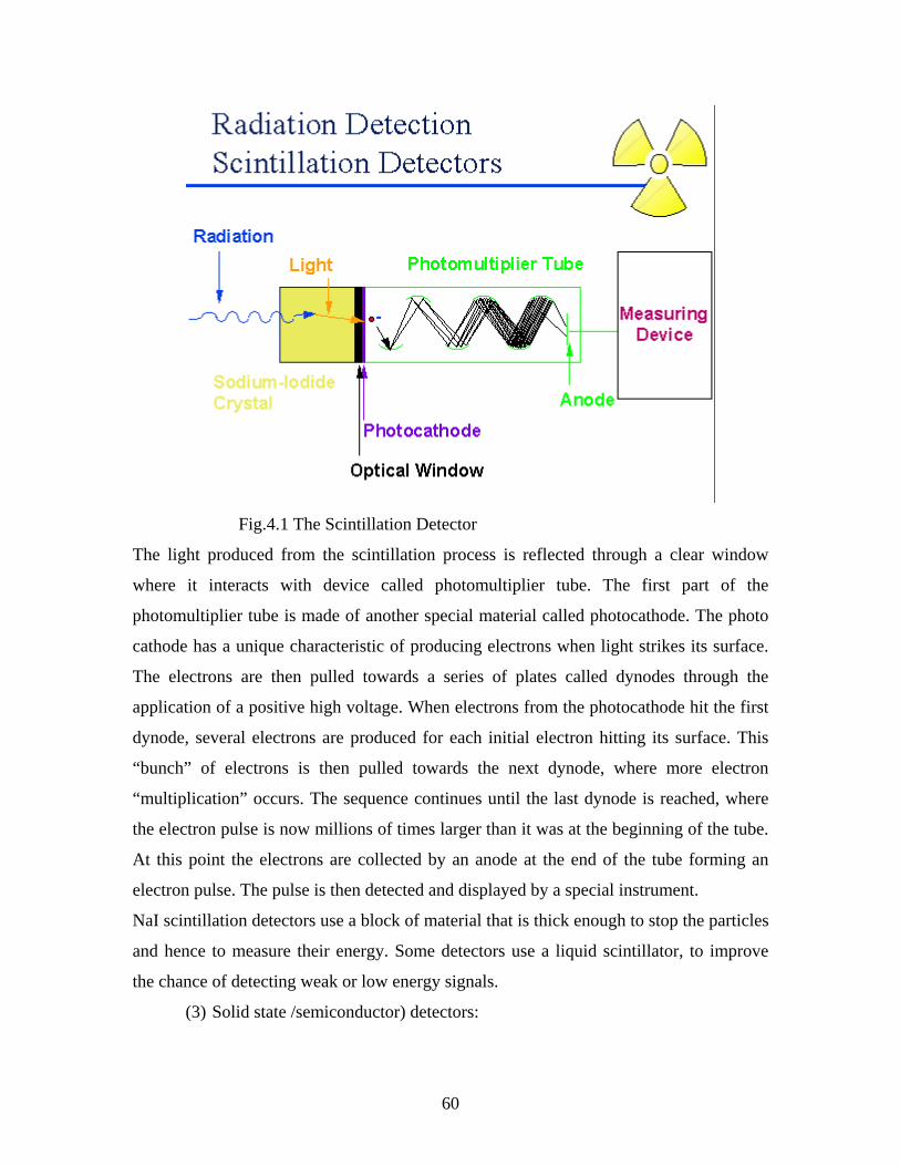
60
Fig.4.1 The Scintillation Detector
The light produced from the scintillation process is reflected through a clear window
where it interacts with device called photomultiplier tube. The first part of the
photomultiplier tube is made of another special material called photocathode. The photo
cathode has a unique characteristic of producing electrons when light strikes its surface.
The electrons are then pulled towards a series of plates called dynodes through the
application of a positive high voltage. When electrons from the photocathode hit the first
dynode, several electrons are produced for each initial electron hitting its surface. This
“bunch” of electrons is then pulled towards the next dynode, where more electron
“multiplication” occurs. The sequence continues until the last dynode is reached, where
the electron pulse is now millions of times larger than it was at the beginning of the tube.
At this point the electrons are collected by an anode at the end of the tube forming an
electron pulse. The pulse is then detected and displayed by a special instrument.
NaI scintillation detectors use a block of material that is thick enough to stop the particles
and hence to measure their energy. Some detectors use a liquid scintillator, to improve
the chance of detecting weak or low energy signals.
(3) Solid state /semiconductor) detectors:
61
One cannot simply replace the gas of an ion chamber by any solid. If the solid is
an insulator, the charges produced by ionization cannot flow to the collecting
plate; if the solid is a conductor a current will flow all the times, making it
difficult to detect the small extra current caused by a passing particle. There are
however, certain materials called semiconductors that can be arranged to act as
insulators except when a charged particle passes through them. by placing a
suitable semiconductor or between two collecting plates, one can make a solid
state that acts much like a gas filled chamber, but can stop a high energy particle
and hence measure its energy – in a much smaller volume.
The solid-state counters are ionization chambers in which the charges released
during the absorption of radiation constitute the signals by which the radiation is
detected. The process by which the radiation is absorbed all involves the
production of one or more high-energy secondary electrons by the primary
radiation. The secondaries in turn produce further ionization and the cascade
process continue until no electron has enough energy to cause further impact
ionization.
In a semiconductor detector, ionizing radiation produces ion pairs (hole- electron
pair), which are collected by the electric field applied externally, and the detector
gives an electrical pulse, which is proportional to the energy of ionizing radiation.
It follows that the number of ion pairs produced will depend only on the energy
deposited by the primary radiation, and will be independent of the type of
radiation. This gives the ion chamber its characteristic linear relation between
signal amplitude and energy deposited, for all particles above certain low
threshold energy.
The energy bands in a semiconductor arise from the allowed energy levels of the
electrons in the individual atoms, which make up the crystal. Semiconductors and
insulators have the property that, at the absolute zero of temperature, where the
available electrons fill the lowest available energy levels, one or more energy
bands are completely full, and the highest filled band is separated from the next
higher band by an energy interval Eg in which there are no allowed levels.
62
In a pure semiconductor, the number of holes and electrons are equal in pure
semiconductor (intrinsic). But impurities or departures from perfect lattice
structure modify this simple picture by introducing localized energy levels,
usually in the forbidden energy gap. Localized centers may become ionized either
by donating an electron to the conduction band (donors) or accepting onefrom the
valence band (acceptors), and the energy needed for these processes will be less
than the energy gap Eg
Lithium drifted germanium (GeLi) detectors are more suitable than silicon
detectors for the detection of electromagnetic radiation. It may be recalled that the
photoelectric absorption cross section for gamma rays is proportional to z5 and
therefore germanium (z = 32) is more efficient than silicon (z = 14) for detection
of gamma rays. The Ge (Li) detector is always maintained in a low temperature
environment to keep up the intrinsic characteristic of germanium. In practice, the
low temperature environment is maintained by a cryostat and liquid nitrogen
(77k) dewar which together with the Ge (Li ) detector from a complete detector
system.
4.3 Gas Filled Detectors
4.3.1 Introduction
Gas filled detectors were the first nuclear radiation detectors to be developed. They are
basically metal chambers filled with gas and containing a positively biased anode wire.
The oldest type of gas filled detectors, which still have important use in nuclear radiation
are:(i) Ionization chambers, (ii) Proportional counters and
(ii) Geiger-Muller counters
In each case of the above type of gas filled detector, an electric field is applied to a
volume of gas enclosed in a chamber. Also RC circuit is connected for the pulse
formation.
They work on the basis of the effect produced when a charged particle passes through a
gas. The primary mode of interaction involves ionization and excitation of gas molecules
along the particle track. The majority of gas filled detectors are based on sensing the
direct ionization created by the passage of the radiation. Their out put signal that
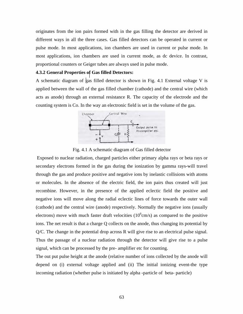
63
originates from the ion pairs formed with in the gas filling the detector are derived in
different ways in all the three cases. Gas filled detectors can be operated in current or
pulse mode. In most applications, ion chambers are used in current or pulse mode. In
most applications, ion chambers are used in current mode, as dc device. In contrast,
proportional counters or Geiger tubes are always used in pulse mode.
4.3.2 General Properties of Gas filled Detectors:
A schematic diagram of gas filled detector is shown in Fig. 4.1 External voltage V is
applied between the wall of the gas filled chamber (cathode) and the central wire (which
acts as anode) through an external resistance R. The capacity of the electrode and the
counting system is Co. In the way an electronic field is set in the volume of the gas.
Fig. 4.1 A schematic diagram of Gas filled detector
Exposed to nuclear radiation, charged particles either primary alpha rays or beta rays or
secondary electrons formed in the gas during the ionization by gamma rays-will travel
through the gas and produce positive and negative ions by inelastic collisions with atoms
or molecules. In the absence of the electric field, the ion pairs thus created will just
recombine. However, in the presence of the applied eclectic field the positive and
negative ions will move along the radial eclectic lines of force towards the outer wall
(cathode) and the central wire (anode) respectively. Normally the negative ions (usually
electrons) move with much faster draft velocities (106cm/s) as compared to the positive
ions. The net result is that a charge Q collects on the anode, thus changing its potential by
Q/C. The change in the potential drop across R will give rise to an electrical pulse signal.
Thus the passage of a nuclear radiation through the detector will give rise to a pulse
signal, which can be processed by the pre- amplifier etc for counting.
The out put pulse height at the anode (relative number of ions collected by the anode will
depend on (i) external voltage applied and (ii) The initial ionizing event-the type
incoming radiation (whether pulse is initiated by alpha -particle of beta- particle)
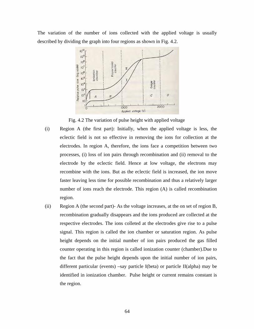
64
The variation of the number of ions collected with the applied voltage is usually
described by dividing the graph into four regions as shown in Fig. 4.2.
Fig. 4.2 The variation of pulse height with applied voltage
(i) Region A (the first part): Initially, when the applied voltage is less, the
eclectic field is not so effective in removing the ions for collection at the
electrodes. In region A, therefore, the ions face a competition between two
processes, (i) loss of ion pairs through recombination and (ii) removal to the
electrode by the eclectic field. Hence at low voltage, the electrons may
recombine with the ions. But as the eclectic field is increased, the ion move
faster leaving less time for possible recombination and thus a relatively larger
number of ions reach the electrode. This region (A) is called recombination
region.
(ii) Region A (the second part)- As the voltage increases, at the on set of region B,
recombination gradually disappears and the ions produced are collected at the
respective electrodes. The ions colleted at the electrodes give rise to a pulse
signal. This region is called the ion chamber or saturation region. As pulse
height depends on the initial number of ion pairs produced the gas filled
counter operating in this region is called ionization counter (chamber).Due to
the fact that the pulse height depends upon the initial number of ion pairs,
different particular (events) –say particle I(beta) or particle II(alpha) may be
identified in ionization chamber. Pulse height or current remains constant is
the region.
65
(iii) In region B, the phenomenon of gas multiplication sets in. Because of the
increased voltage, the electrons which are liberated by the primary ionizing
event get sufficient kinetic energy to cause secondary ionization. This
secondary ionization increases the amount of collected charge. In the first part
of the region B, the gas multiplication factor M is strongly dependent on the
particle energy for a given applied voltage. In other words, in this region, the
detector will give rise to pulses of different heights depending on whether; the
initial ionization is caused by alpha particle or beta particle. This
proportionality between the pulse height and the initial ionization allows us to
use the detector to distinguish between particles of different energies and
ionizing powers. The gas filled counter operating in this region is called
proportional counter. As the applied voltage is increased this proportionality
breaks down. The region B is called proportional region, while at its upper
ends it’s called region of limited proportionality.
(iv) Beyond the proportionally region, the pulse size is completely in dependent of
the initial ionization and all particle produce pulse of the same height
irrespective of their energy and primary ionization. I.e. Event r minimum
ionizing particle will produce a very large pube. Pubes here can be recorded
with out amplification. This region C is called Geiger-Muller region. If the
voltage is increased beyond the region C there will be an on set of continuous
electrical discharge. The gas filled counter operating is this region is called
Geiger counter or Geiger Muller counter or G.M counter.
4.3.3 Ionization Chambers
Ion chambers in principle are the simplest of all gas filled detectors. Their normal
operation is based on collection of the entire charges created by direct ionization with
in the gas through the application of an eclectic field. Exclusively the term ionization
chamber is used for type detectors in which ion pairs are collected from gases.
As fast charged particles passes through a gas they create both exited molecules and
ionized molecules along its path due to the Collision. After the neutral molecule is
ionized, the resulting positive ion and free electron are called an ion pair, and it serves
as the basic constituent of the electrical signal developed by the ion chamber. Ions
66
can be formed either by direct integration with the incident partied or through a
secondary process in which some of the particle energy is first transferred to an
energetic electrons or delta rays.
At a minimum, the particle must transfer and amount of energy equal to ionization
energy of the gas molecule to permit the ionization process to occur. In most gases
used for radiation detectors, the ionization energy of least tightly bound electron
shells is between 10 and 25 ev. However there are other mechanisms by which the
incident particle may lose energy with in the gas that do not create ions. Examples are
the excitation process in which an electron may be elevated to a higher bound state in
the molecule without being completely removed. Therefore, the average energy lost
by the incident particle per ion pair formed (defined as w-value) is always
substantially greater than the ionization energy. The W- value in principle is a
function of a species of gas involved, the type of radiation, and its energy. Empirical
observations, however, show that it is not a strong function of any of these variables
and is remarkable constant parameter of value 25-35 per ion pair for many gases.
Assuming that W is constant for a given type of radiation, The deposited energy will
be proportional to the number of ion pairs formed and can be determined if a
corresponding measurement of the number of ion pairs is carried out. For example in
the case of argon gas, Ar Ar++e- (ion pair formation). If E is the energy loss,
then the ion pairs produced can be found by the relation,
Ion pairs= E/w (4.1)
Were W is the energy required to produce one ion pair ( W=30ev) If V is an applied
voltage across the electrode, the electric field between the two electrode is
E = V/d. (4.2)
An ionization chamber can have various geometries, The basic systems being similar
to shown in Fig. 4.1 .The external voltage applied between the two electrodes is
properly adjusted for operation in region A (second part) .The gas used in the
chamber is either dry air at normal pressure or some other suitable gas (dense gas
such as argon). The fill gas pressure is often1atmosphere, although higher pressure is
sometimes used to increase the sensitivity. When the ionization chamber is to be used
for intensity measurements one usually measures its ionization current with a system.
67
The ionization current of chamber exposed to nuclear radiation first increases with
applied voltage but soon saturates to a saturation current value, IS because at this
voltage all the primary ions are collected before they can recombine.
The voltage at which saturation sets in is determined by the intensity of the incident
nuclear radiation. If the number of ion pairs produced per second in N, the average
ionization current IS at saturation is given by Is= Ne, where e is the electronic
charge. Then measurements of IS can give us the integrated effect of the total
ionization events or the intensity of ionizing radiation. The ionization current is
measured either by a micro ammeter or by some other sensitive method.
4.3.4.1 Proportional Counters
A proportional counter is a type of gas filled detector that was introduced in the late
1940s. It is usually built in a cylindrical geometry, with a hollow metal cylinder
forming the outer electrode (cathode) while a fine tungsten wire (diameter of about
0.1mm) running along the axis forming the central electrode (anode). The applied
voltage is adjusted so as to be in the proportionality region B (Fig. 4.2)
For a cylindrical geometry, the strength of the electric field at a radial distance r from
the central wire is given by: E =)/ln( abr
Vo (4.3)
Where Vo is the applied voltage and a and b are the radii of the central wire and the
cylindrical electrodes respectively. The electric field in the neighbourhood of the
central wire is very high and such high electric field causes gas multiplication. Gas
multiplication is a consequence of increasing the electric field within the gas to
sufficiently high value. Because electrons are attracted to the anode, they will be drawn
toward this high field region.
Free electrons can be easily accelerated by the applied electric field & may have
significant kinetic energy when undergoing collission. If its kinetic energy is greater
than the ionization energy of the neutral gas molecule, it is possible for additional ion
pairs to be created in the collisions. In a typical gases at atmospheric pressure the
threshold field is of the order of 106v/m. If the field is above the threshold field for the
secondary ionization, the electrons liberated by the secondary ionization process will
68
also be accelerated by the electric field. During its subsequent drift, it undergoes
collisions with other neutral gas and thus can create additional ionization.
When the electrons of the initial ionization reach the region of high field strengths, they
can pick up enough kinetic energy between collisions to make more ions; electrons so
formed can continue the process. This is called an avalanche. Avalanche effects were
first used to detect single particles by Rutherford and Geiger in 1908. If there were no
ion pairs initially, Mno electrons & Mno positive ions will be formed, mostly in the
space very close to the wire when the avalanche has stopped. The avalanche terminates
when all free electrons have been collected at the anode. As we raise the counter
potential, the avalanches are more effective so that M is larger. One usually gets
multiplication factors M in the range of 102-104.
To understand the gas multiplication let us assume that every electron produced in the
primary ionization gives rise to a total of n secondary electrons by collisions. The
production of secondary electrons during the collisions in the gas will also give rise to
photons, which in turn can produce photoelectrons in the volume of the counter. Let p
be the probability that each secondary electron will give rise to a photoelectron. Thus
there will be np photoelectrons, in turn, produces n electrons by further collissions. We
shall have a second generation avalanche of n2p electrons, which in turn give rise to
more photo electrons and so on. Finally, the total number of electrons will be: M = n +
n2p +n3p2 + …………. (4.4)
Where M is the gas multiplication factor. For practical proportional counter, np < 1 and
the above series converges so that M can be written as a sum of geometric series,
.e. M = n (1 + n 2p2 + n 3p 3 ………………)
= np
n−1
(4.5)
It is thus seen from the result that in a proportional counter the total number of
secondary electrons is proportional to the number of initial or primary ion pairs, but
with the total number of ions multiplied by a factor of M.This charge amplification
within the detector itself reduces the demands on external amplifiers and can result in
significantly improved signal to noise characteristics compared with pulse type ion
chambers.
69
According to Townsend avalanche, each free electron created in a collission can
potentially create more free electrons for additional ionization in the form of cascade of
gas multiplication process. Hence the fractional increase in the number of electrons per
unit path length is governed by the Townsend equation;
n
dn = α dx (4.6)
where α is called the first Townsend coefficient. Its value is zero for electric field
values below the threshold and generally increases with increasing field strength above
this minimum. For spatially constant field (as in parallel plate geometry), α is a
constant in Townsend equation Its solution then predicts that the density of electrons
grows exponentially with distance as the avalanche progresses:
n(x) = n(0) eαx (4.7)
one of the important application of proportional counters has been in the detection and
spectroscopy of low energy x-radiation. Also they are widely applied in the detection of
neutrons. In addition proportional counters can be applied to situations in which the
number of ion pairs generated by the radiation is too small to permit satisfactory
operation in the pulse type ion chambers due to their considerably larger pulse
formation.
4.3.5GEIGER MULLER COUNTERS
The Geiger Muller counter (commonly referred to as the G.M. counter, or simply a
G.M. tube) is one of the oldest radiation detector types in existence, having been
introduced by Geiger and Muller in 1928.
If the anode potential of a proportional counter is raised sufficiently the output pulse
fails to remain proportional to the primary ionization and finally become of uniform
amplitude, irrespective of the type of energy of the incident particle or photon. The
counter is then said to be operating in Geiger region.(C)
G.M.counters are usually filled with noble gases like argon, neon, helium etc. In the Geiger Muller region C (Fig.4.2) np < 1and the series in equation 4.4 diverges. We have therefore a new phenomenon in the Geiger region. It is the spread of the discharge along the wire by the action of photon generated in the avalanche. The result is that the discharge spreads all along the wire forming an ion sheath and an out put pulse of the order of few volts is obtained, (independent of the primary ionization). This discharge has to be quenched. Otherwise it can sustain itself and multiple pulses can occur. There are two ways in which this discharge can be quenched, (i) externally- by suitable electronic

70
circuit or (ii) more simply in an internal way by adding a poly atomic gas, like ethyl alcohol vapour, to the argon gas (ratio argon 90% by weight, ethyl alcohol 10%).Let me explain the above two cases in detail.
(i) External Quenching: The mechanism of operation depends upon emission of
ultraviolet radiation (photons) from many atoms excited during the avalanche of
electrons towards the anode wire. In the earlier forms of Geiger counter these photons
eject photoelectrons from the metal walls of the counter. The photoelectrons are
accelerated towards the anode, near which they produce further avalanche, which
spread in this manner along the entire length of the anode. The process ceases only
when the space charge of slowly moving
Positive ions reduce the electric field sufficiently to limit the number of electrons and
excited atoms in the avalanche. When, eventually, positive ions reach the cathode they
also may eject photoelectrons and so initiate a self-sustaining discharge in the counter. A
number of electronic circuit arrangements have been devised to prevent secondary pulses
due to positive ion impacts. This may be accomplished electronically by lowering the
voltage v after each count, which in turn lowers the speed of the counter. Such counters
are called non- self-quenching.
To decrease the attracting potential, which is responsible for motion&multiplication of
electrons emitted from the cathode, we can use (apply) an external resistance.
If vo is an applied voltage which is creating VO C
high field, it is decreased when a current I flows through the resistance R. Then the R
potential at the central wire becomes vo-IR.
If the resistance is made very high, now +
Since the potential is vo-IR rather than Fig. 4.3 External quenching circuit
Vo there is no electron reaching the central wire.
Therefore in external quenching (i) we can use high value of resistance, R or (ii) we can
use some electronic circuit which are called quenching circuit, that dis connects the
voltage for a moment from the central wire.
(ii) Internal Quenching: More elegantly the quenching is done in a gas itself. For
discharge to maintain itself, either one or more of the huge number of positive ions
71
formed in an avalanche or a photon must release a new electron in the gas or at the
cathode to start the process over again.
When a positive argon ion, is neutralized on a metallic surface a considerable amount of
energy is released that may be used to expel an electron from the surface. This makes
using argon alone difficult. But polyatomic gases do not behave this way.
Here I consider only counters filled with mixtures of mono atomic gas (commonly argon)
and a polyatomic gas such as ethyl alcohol. An argon pressure of 9cm of mercury (Hg)
and alcohol pressure of 1cm Hg are common. Counters containing polyatomic gases are
called self-quenching; they will operate without need for external circuit. A small amount
of polyatomic vapour such as alcohol or acetone is introduced into the gas filling. This
causes photons from the electron avalanche to be strongly absorbed in the vapour, owing
to its low ionization potential, and photoelectrons are produced close to the anode wire.
The quenching action of alcohol is as follows: the ionization potential of alcohol (11.3ev)
is lower than that of argon (15.7). As a result the ions moving out towards the outer
cathode consist mostly of alcohol ions. These alcohol ions, however do not give rise to
secondary avalanche when they are neutralized at the cathode. Thus there is no multiple
pulsing and the discharge is quenched soon (fraction of a millisecond) after the initial
ionization.
Since the ionization energy of alcohol is less than that of argon, we get :
Ar+ +C2H5OH Ar + (C2H5OH)+,
While going towards cathode Ar+ loses their charge to alcohol. When alcohol molecules,
(C2H5OH)+ reach the cathode they become neutral by absorbing electrons from the
cathode. But since dissociation energy of alcohol molecules is very low ( ≈ 3ev) they
dissociate into C2H5+and OH-and no photon emission that can lead to photoelectrons. So,
that way secondary discharge is quenched. However, gradually alcohol molecules can be
exhausted and result in poor characteristics of G.M.tube because gas pressure slowly
increases due to the increase in molecular fragments.
Therefore, self-quenching has got a lifetime, i.e. lifetime not in terms of time but in terms
of number of particles due to the gradual decomposition of organic vapour. This depends
upon the utilization of alcohol molecule (dissociation). Organic quenched tubes have a
useful lifetime of about 1010 counts. To solve this problem halogen quenching gases such
72
as chlorine, bromine, etc are used. In the halogen- quenched tube, the quenching gas is
apparently not consumed in the quenching process. It appears that the diatomic halogen
gas molecules are dissociated in the quenching, and that there is a recombination
mechanism present to replenish the supply of quenching gas. Unlike alcohol after
dissociation chlorine is regained so that the problem of exhaustion is solved. This not
only extends greatly the life of the tube for a normal use, but also makes possible to run
the tube at higher voltages without sacrificing the life of the tube. This later feature
means that the out put voltage pulse of 10volts or more can be obtained from the tube in
normal operation. But the halogen vapours cannot be used with some cathode materials
because of chemical action. Cathodes of stainless steel have proved satisfactory. Self-
quenching counters containing halogen fillings have indefinite lives because the halogen
ions are neutralized at the walls without dissociation (or electron emission). Nearly all-
modern Geiger counters are of this type.
4.5.1 Some Basic Features of G.M.counter
(1) Design Features: Geiger Muller counter (G.M.) can be built in various geometries.
Atypical design of Geiger tube is the end window type. (Illustrated in. Fig. 7.6). The
anode wire is supported at one end only and is located along the axis of the cylindrical
cathode made of metal or glass with a metallized inner coating. Radiation enters the tube
through the entrance window, which may be made of mica or other material that can
maintain its strength in thin sections. Because most Geiger tubes are operated below
atmospheric pressure, the window may have to support substantial differential pressure.
The window should be as thin as possible when counting short-range particles, such as
alphas, but may be made robust for applications that involve beta particles or gamma
rays.
(2) Time behavior: immediately following the Geiger discharge, the electric field has
been reduced below the critical point by the positive space charge. If another ionizing
occurs under these conditions, a second pulse will not be observed because gas
multiplication is prevented. During this time the tube is therefore ‘dead’ and any radiation
interactions that occur in the tube during this time will be lost. Technically, the dead time
of the Geiger tube is defined as the period between the initial pulse and the time at which
the second Geiger discharge, regardless of its size can be developed. In most Geiger
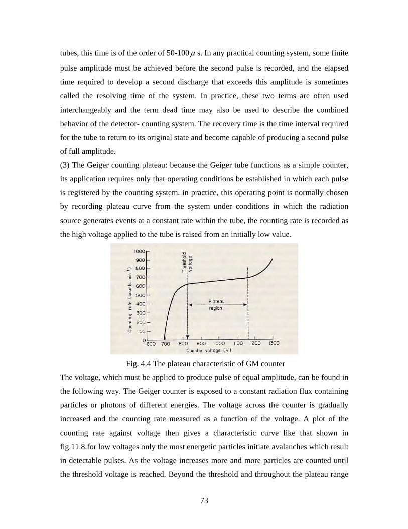
73
tubes, this time is of the order of 50-100 μ s. In any practical counting system, some finite
pulse amplitude must be achieved before the second pulse is recorded, and the elapsed
time required to develop a second discharge that exceeds this amplitude is sometimes
called the resolving time of the system. In practice, these two terms are often used
interchangeably and the term dead time may also be used to describe the combined
behavior of the detector- counting system. The recovery time is the time interval required
for the tube to return to its original state and become capable of producing a second pulse
of full amplitude.
(3) The Geiger counting plateau: because the Geiger tube functions as a simple counter,
its application requires only that operating conditions be established in which each pulse
is registered by the counting system. in practice, this operating point is normally chosen
by recording plateau curve from the system under conditions in which the radiation
source generates events at a constant rate within the tube, the counting rate is recorded as
the high voltage applied to the tube is raised from an initially low value.
Fig. 4.4 The plateau characteristic of GM counter
The voltage, which must be applied to produce pulse of equal amplitude, can be found in
the following way. The Geiger counter is exposed to a constant radiation flux containing
particles or photons of different energies. The voltage across the counter is gradually
increased and the counting rate measured as a function of the voltage. A plot of the
counting rate against voltage then gives a characteristic curve like that shown in
fig.11.8.for low voltages only the most energetic particles initiate avalanches which result
in detectable pulses. As the voltage increases more and more particles are counted until
the threshold voltage is reached. Beyond the threshold and throughout the plateau range
74
all pulses are of approximately the same amplitude and the counting rate remains almost
constant. Infact the plateau has a positive slope corresponding to about a 1percentrise in
the counting rate over the plateau length. The working voltage of the counter is taken to
be midway along the plateau so that variations in the supply voltage do not greatly affect
the counting rate.
4.3.5.2 Detection Efficiency
All radiation detectors will, in principle, give rise to an out put pulse for each quantum of radiation that interacts within its active volume. For primary charged radiation such as alpha or beta particles, interaction in the form of ionization or excitation will take place immediately upon the entry of the particles into the active volume. After traveling a small fraction of its range, a typical particle will form enough ion pairs along its path to ensure that the resulting pulse is large enough to be recorded. thus it is often easy to arrange a situation in which a detector will see every alpha or beta particle that enters its active volume. Under these conditions, the detector is said to have a counting efficiency of 100% On the other hand, uncharged radiations such as gamma rays or neutrons must first
undergo a significant interaction in the detector before detection is possible. Because
these radiations can travel large distance between interactions, detectors are often less
than 100% efficient. It then becomes necessary to have a precise figure for the detector
efficiency in order to relate the number of pulses counted to the number of neutrons or
photons incident on the detector.
It is convenient to subdivide counting efficiencies into two classes: absolute and intrinsic.
Absolute efficiencies are defined as:
εabs = ebythesourcntaemitteddiationquanumberofra
edlsesrecordnumberofpu (4.8)
and are dependent not only on detector properties, but also on the details of counting geometry (primarily the distance from the source to the detector ).the intrinsic efficiency is defined as :
εint = ectortonntaincidendiationquanumberofra
edlsesrecordnumberofpudet
(4.9)
and no longer includes the solid angle subtended by the detector as an implicit factor. the two efficiencies are simply related to isotropic source by εint = εabs(4π/Ω ), where Ω is the solid angle of the detector seen from the actual source position. Usually, not all the particles reaching the detector are counted. Some are missed because they don’t produce enough excitation to be counted. Which of them will be missed
75
cannot be predicted, because excitation and ionization of the counter media by the incident particle is a random phenomenon. The efficiency of the detector gives, the probability that a given detector will count the incident particle The intrinsic efficiency of a detector usually depends primarily on the detector material, the radiation energy and the physical thickness of the detector in the direction of the incident radiation. A slight dependence on the distance between the source and detector does remain, however, because the average path length of the radiation through the detector will change somewhat with this spacing. Counting efficiencies are also categorized by the nature of the event recorded. If we accept all pulses from the detector, then it is appropriate to use total efficiencies. In this case all interactions no matter how low in energy, are assumed to be counted. In terms of a hypothetical differential pulse height distribution, the entire area under spectrum is a measure of the number of all pulses that are recorded, regardless of the amplitude, and would be counted in defining the total efficiency. In practice, any measurement system always imposes a requirement that pulses be larger than some finite threshold level as low as possible. the peak efficiency, however, only those interactions assumes that deposit of the full energy of the incident radiation are counted. in a differential pulse height distribution, these full energy events are normally evidenced by a peak that appears at the highest end of the spectrum. Events that deposit only part of the incident radiation energy then will appear further to the left in the spectrum. the number of full energy events can be obtained by simply integrating the total area under the peak. The total and the peak efficiencies are related by the peak to total ratio: r =εpeak/εtotal Which is sometimes tabulated separately. It is often preferable from an experimental standpoint to use only peak efficiencies, because the number of the full energy events is not sensitive to some perturbing effects such as scattering surrounding objects or spurious noise. Therefore, values for the peak efficiency can be compiled and universally applied to a wide variety of laboratory conditions, whereas total efficiency values may be influenced by variable conditions. To be complete, a detector efficiency should be specified according to both of the above criteria. for example, the most common type of efficiency tabulated for gamma ray detectors is the intrinsic peak efficiency. A detector with known efficiency can be used to measure the absolute activity of a radioactive source. Let us assume that a detector with an intrinsic peak efficiency ε ip has been used to record N events under the full energy peak in the detector or spectrum. For simplicity, we also assume that the source emits radiation isotropically and that no attenuation takes place between the source and the detector. From the definition of intrinsic peak efficiency, the number of radiation quanta, S, emitted by the source over the measurement period is then given by : S = N4π/εIPΩ (4.10) Where Ω represents the solid angle (in steradians) subtended by the detector at the source
position. I.e. εIP = εAP(4π/Ω) & εAP = SN
⇒ S = N/εAP
⇒ S =4πN/εIPΩ (4.11)
Where εAP is absolute peak efficiency.
76
The solid angle is defined by an integral over the detector surface that faces the source, of
the form: Ω = ∫ (cosα ⁄ r2)Da (4.12)
Where r represents the distance between the source and the surface element dA, and α is the angle between the normal to the surface element and the source direction. If the volume of the source is not negligible, then a second integration must be carried out over all volume elements of the source.for the common case of a point source located along the axis of a right circular cylindrical detector, Ω is given by :
Ω = 2π[1− d/ √(d2 + a2)] (4.13)
where the source detector distance d and detector radius a , for d >>a, the solid angle reduces to the ratio of the detector plane frontal area A visible at the source to the square of the distance: Ω ≈ A⁄ d2 = πa2⁄ d2 (4.14) (as d ⁄ √ (d2 + a2) = 1 ⁄ √ (1 + a2 ⁄ d2) = (1 + a2 ⁄ d2)−1/ 2 ≈ 1 - a2 ⁄ 2 d2
Ω = 2π [1 - (1 – a2 ⁄ 2d2)] = 2π a2 / 2d2 = π a2 / d2 )
hence for a point source at a distance d from the counter window of the radius r, the variation of the solid angle is related to the geometric factor GP according to the equation
GP = Ω / 4π = 21 (1 – d / √ (d2 + r2 )
= Ω/ 4π = r2 / 4 d2 (4.15) Therefore including the geometric factor and taking into account the property of the material (absorption coefficient) for a given beta and gamma source (i) the efficiency for gamma of GM counter is given by the formula: ε γ = [ (Iγ (1 + μx) / 2AGP] × 100% (4.16)
and (ii) efficiency for β-rays is given by the relation : ε β = [ 2I β γ / 3Iγ (1+ μx)] × 100% (4.17)
where Iγ = Intensity of γ -source (or the number of counts per unit time ) with absorber. I β γ =Intensity of gamma source without absorber,
μ = absorption coefficient of an absorber, x = thickness of the absorber, A = Present day activity of the absorber,
& GP = geometric factor. The intrinsic efficiency of a Geiger Muller counter is equal to the probability that at least
one ion pair will be produced by a particle passing through it. Suppose that, on average,
N primary ion pairs are produced by the particle. The chance that no ion pair will be
produced is e-N. The efficiency is then 1 – e-N, because only if no ion pair will be
produced will a count fail to occur. For N = 4 this quantity is 98 %; beta and alpha
efficiencies can thus easily be made close to unity. On the other hand the efficiency of a
Geiger Muller counter for photons is normally about 1%, varying appreciably with
energy.
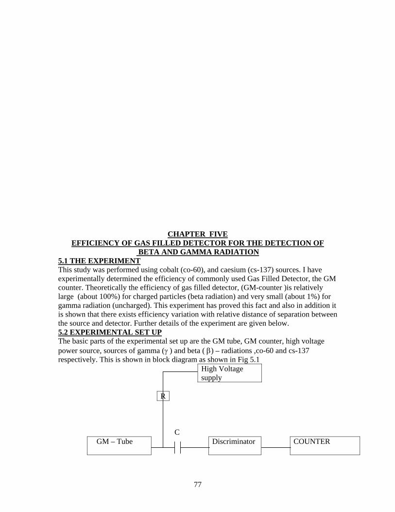
77
CHAPTER FIVE
EFFICIENCY OF GAS FILLED DETECTOR FOR THE DETECTION OF BETA AND GAMMA RADIATION
5.1 THE EXPERIMENT This study was performed using cobalt (co-60), and caesium (cs-137) sources. I have experimentally determined the efficiency of commonly used Gas Filled Detector, the GM counter. Theoretically the efficiency of gas filled detector, (GM-counter )is relatively large (about 100%) for charged particles (beta radiation) and very small (about 1%) for gamma radiation (uncharged). This experiment has proved this fact and also in addition it is shown that there exists efficiency variation with relative distance of separation between the source and detector. Further details of the experiment are given below. 5.2 EXPERIMENTAL SET UP The basic parts of the experimental set up are the GM tube, GM counter, high voltage power source, sources of gamma (γ ) and beta ( β) – radiations ,co-60 and cs-137 respectively. This is shown in block diagram as shown in Fig 5.1
High Voltage supply
R
C
GM – Tube
Discriminator COUNTER
78
Fig. 5.1 Block diagram of counting electronics associated with a GM – tube.. 5.3 EXPERIMENTAL TECHNIQUES (Methods) To achieve the desired result, measurement of efficiency, there are some basic techniques (methods) that I used before experiment (as a pre condition)and in the experiment. I have mentioned the steps that I have followed orderly. Step 1: calculations of activities of the sources used in the experiment. The experiments in nuclear physics lab (AAU) started in Dec.1993 there were caesium and cobalt sources by that time. I used the same source for this experiment. Based on evidences, I have come to the conclusion that the initial activities of the respective sources are
(i) For cobalt source (co-60), A0 = 1μCi (ii) For caesium source (Cs – 137), A0 = 5μCi
Based on this, taking the data of manufacture to be in 1993, the total time of decay upto now will be 13.5 yrs. Using this the activities can be calculated as follws.
(i) For cobalt source (Co – 60): - Half life, T1/2 = 5.27yrs - Time of decay, t = 13.5 yrs
From the exponential decay relation, the present activity of cobalt is defined by the formula : A = A0e-λt (2.6) Where λ is decay constant and t is time of decay. But for cobalt source (Co – 60)the decay constant is, λ = 0.693 ⇒ λ = 0.693 = 0.131/yr (2.3) T1/ 2 5.27yr Then the present activity becomes, A = A0e-λt = 1μCi × e-1.775 = 0.1695μCi since 1curie = 1Ci = 3.7 × 10¹⁰disintegrations /sec we can also write the activity as, A = 0.1695 × 10-6 × 3.7 × 1010
=0.2715 × 10⁴ dis / sec = 6,271.5 dis / sec
(ii) For caesium source (Cs – 137) - Half life, T1 / 2 = 30.1yrs - Decay time, t = 13.5 yrs
Again from the exponential decay relation, the present activity of caesium is given by the equation (2.6), where the decay constant, λ for caesium is : λ = 0.693 ⇒ λCS = 0.693 = 0.023023 / yrs T1 / 2 30.1yrs Then taking the initial activity , A0 = 5μ Ci, the present activity of caesium source can be calculated to be ; A = A0e-λt ⇒ A = 5μCi × e-0.3108
=5μCi × 0.73285 = 3.66425μCi but since 1μCi = 3.7 × 10¹⁰ dis / sec, we can also write this as A = (3.664251037 × 10⁻⁶)(3.7 × 10¹⁰dis /sec) = 13 55772884 × 104 dis / sec = 135,577.2884 dis / sec. Therefore I used : ACO = 6,271.5 dis / sec for cobalt source (Co – 60),
79
and ACS = 135,577.2884 dis / sec for caesium (Cs – 137) as a present day activity.
Step 2 Calculation of the proper absorber thickness for beta absorption and absorption coefficient
(a) Energy relations of the sources used is shown in table 5.1 below. S. No. Source Type of Radiation Energy
β- rays (maximum) Of Emitted γ - rays
1 Cobalt (Co – 60) β & γ radiations 0.31Mev 1.17 & 1.33 2 Caesium(Cs 137) β & γ radiations 0.51 Mev 0.66 Mev
Table 5.1
(b) according to the equation (3.21) the range of beta rays in a given material (absorber)is related to its maximum energy according to :
R0 = 412 En for 0.01 < E < 3Mev ` (3.22) And n = 1.265 – 0.0954lnE Since the energy of both beta sources are within this range. (i) for cobalt (co – 60): E = 0.31Mev n = 1.265 - 0.0954lnE =1.265 + 0.111730856 n = 1.37673 then from R = 412 En we obtain, R01 = 412 (0.31) 1..37673 =412 × 0.1994 =82. 15 mg / cm3 this is the range of cobalt source (Co – 60) in any absorber thickness that can absorb beta rays totally. But since I used aluminium in this experiment, as an absorber the corresponding proper absorber thickness will be:
X 1 = ρ
1Ro =
gmg
73.215.82 (cm3 / cm 3) = 30.09 × 10 –3 cm
= 30.09 × 10 –2 mm = 0.3009 mm (ii) for caesium(Cs – 137): E 0.51 Mev n = 1.265 - 0.095 ln E = 1.265 0.0954ln (0.51) = 1.265 + 0.0642 = 1.32923707 this gives, R CS = 412 × (0.51) 1 32923707 = 412 × 0.040859 = 168. 3405159 mg / cm 3 this is caesium – 137 beta range in any absorber. It also gives the absorber thickness for its total absorption. Then the equivalent proper thickness of aluminium absorber can be
calculated to be: x CS = ρ
Rcs ⇒ x CS = gmg
73.234.168 = 61. 663 × 10 –3 cm
= 61. 663 × 10 –2 mm = 0.61663 mm. Based on the above results I used:
80
(i) x CO = 0.315 mm (combination of absorbers – [0.27mm + 0.045mm]) for cobalt and (ii) x CS = 0.67 mm (again combination of two absorbers [0.40mm + 0.205]) for caesium as absorber thickness to totally block beta radiation. (C) Also I have calculated the mass absorption coefficient s using the equation given by: μ m = 17(E)-1.43 cm2 / gm. (3.21) where μ m is mass absorption coefficient and E is energy of β - emitter in Mevs. (i) thus for cobalt, μm = 17(0.31) – 1.43 cm2 / gm = 17(5.337682999) = 90.74 cm 2 / gm. (mass absorption coefficient) & equivalently we can define the linear absorption coefficient corresponding to this for aluminium as: μ = μ m ρ ⇒ μ = 90. 74 cm 2 / gm × 2.73 g / cm 3 or μ = 247.721868 cm –1 (ii) for caesium (Cs – 137): E = 0.51Mev. then μ m = 17(0.51) – 1. 43 = 17(2.619) = 44.527 cm 2 / g equivalently the linear absorption coefficient for this case will be:
μ = μ m ρ = 121. 5587475 cm –1.
5.4 Experiment II Title: The plateau characteristic of GM counter
Objective: to determine the operating voltage of GM counter 5.4.1 Experimental procedure:
(1) Clamp the Geiger tube to a retort stand and then connect the GM counter (scaler) & high voltage supply for normal counting. Make sure that the voltage is set at its lowest value. – I set the time of counts to be 100sec & started from 300 v.
(2) Place cobalt / caesium source (Cs – 137) at a fixed distance on the source holder. I used caesium source (Cs – 137) at a distance of 3 cm from the source (without correction factor)
(3) Gradually increase the voltage until the scaler begins to register pulses. I varied the voltage at 10-v interval and repeated the intensity measurement at least five times for each voltage.
(4) Measure the counting rate at various voltages, until the counting rate begins to rise rapidly. Do not allow the counter to operate for prolonged periods in the continuous discharge region, as this will damage the counter.
.Table 5.2. the plateau characteristic of GM counter.
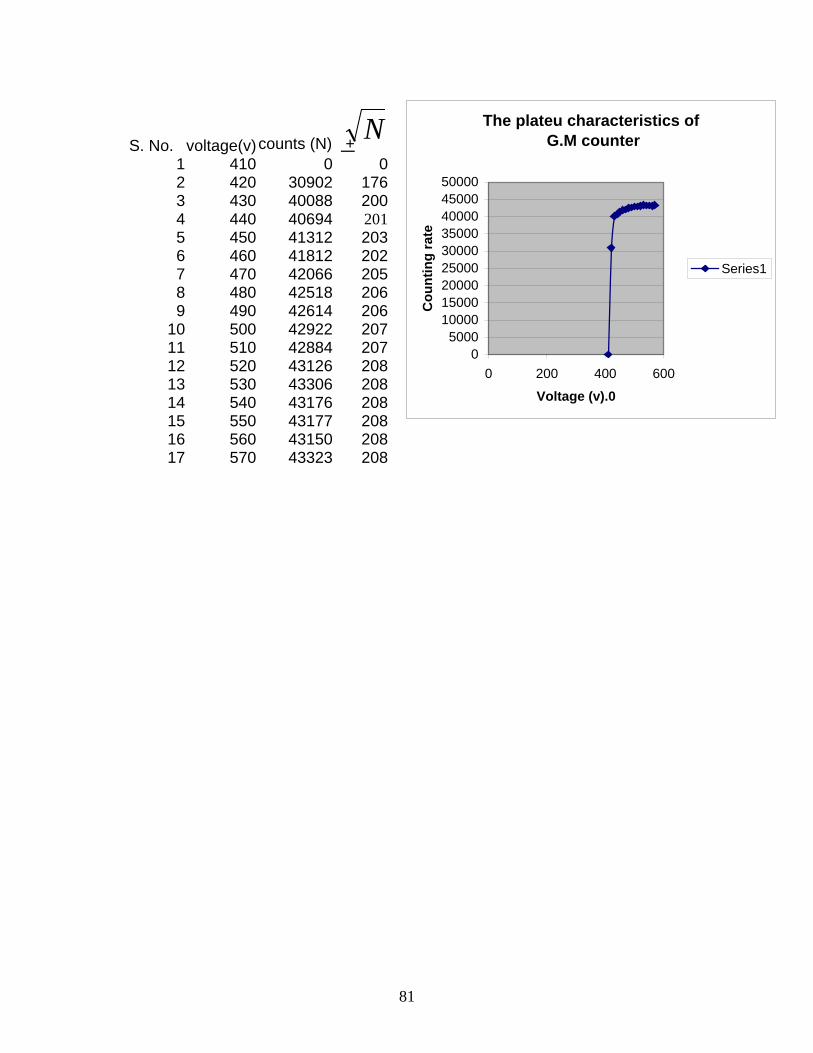
81
The plateu characteristics of G.M counter
05000
100001500020000250003000035000400004500050000
0 200 400 600
Voltage (v).0
Cou
ntin
g ra
te
Series1
S. No. voltage(v)
counts (N) + 1 410 0 02 420 30902 1763 430 40088 2004 440 40694 2015 450 41312 2036 460 41812 2027 470 42066 2058 480 42518 2069 490 42614 206
10 500 42922 20711 510 42884 20712 520 43126 20813 530 43306 20814 540 43176 20815 550 43177 20816 560 43150 20817 570 43323 208
N
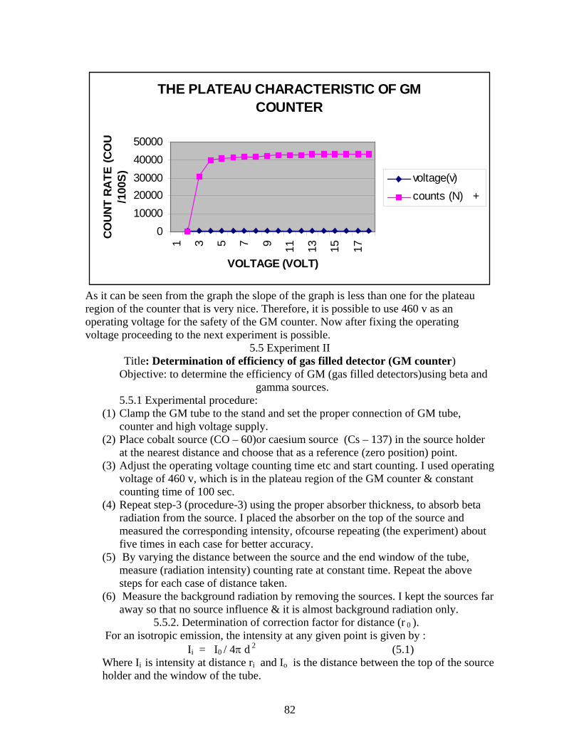
82
THE PLATEAU CHARACTERISTIC OF GM COUNTER
01000020000300004000050000
1 3 5 7 9 11 13 15 17
VOLTAGE (VOLT)
CO
UN
T RA
TE (C
OU
/100
S) voltage(v)counts (N) +
As it can be seen from the graph the slope of the graph is less than one for the plateau region of the counter that is very nice. Therefore, it is possible to use 460 v as an operating voltage for the safety of the GM counter. Now after fixing the operating voltage proceeding to the next experiment is possible.
5.5 Experiment II Title: Determination of efficiency of gas filled detector (GM counter)
Objective: to determine the efficiency of GM (gas filled detectors)using beta and gamma sources. 5.5.1 Experimental procedure:
(1) Clamp the GM tube to the stand and set the proper connection of GM tube, counter and high voltage supply.
(2) Place cobalt source (CO – 60)or caesium source (Cs – 137) in the source holder at the nearest distance and choose that as a reference (zero position) point.
(3) Adjust the operating voltage counting time etc and start counting. I used operating voltage of 460 v, which is in the plateau region of the GM counter & constant counting time of 100 sec.
(4) Repeat step-3 (procedure-3) using the proper absorber thickness, to absorb beta radiation from the source. I placed the absorber on the top of the source and measured the corresponding intensity, ofcourse repeating (the experiment) about five times in each case for better accuracy.
(5) By varying the distance between the source and the end window of the tube, measure (radiation intensity) counting rate at constant time. Repeat the above steps for each case of distance taken.
(6) Measure the background radiation by removing the sources. I kept the sources far away so that no source influence & it is almost background radiation only.
5.5.2. Determination of correction factor for distance (r 0 ). For an isotropic emission, the intensity at any given point is given by : Ii = I0 / 4π d 2 (5.1) Where Ii is intensity at distance ri and Io is the distance between the top of the source holder and the window of the tube.
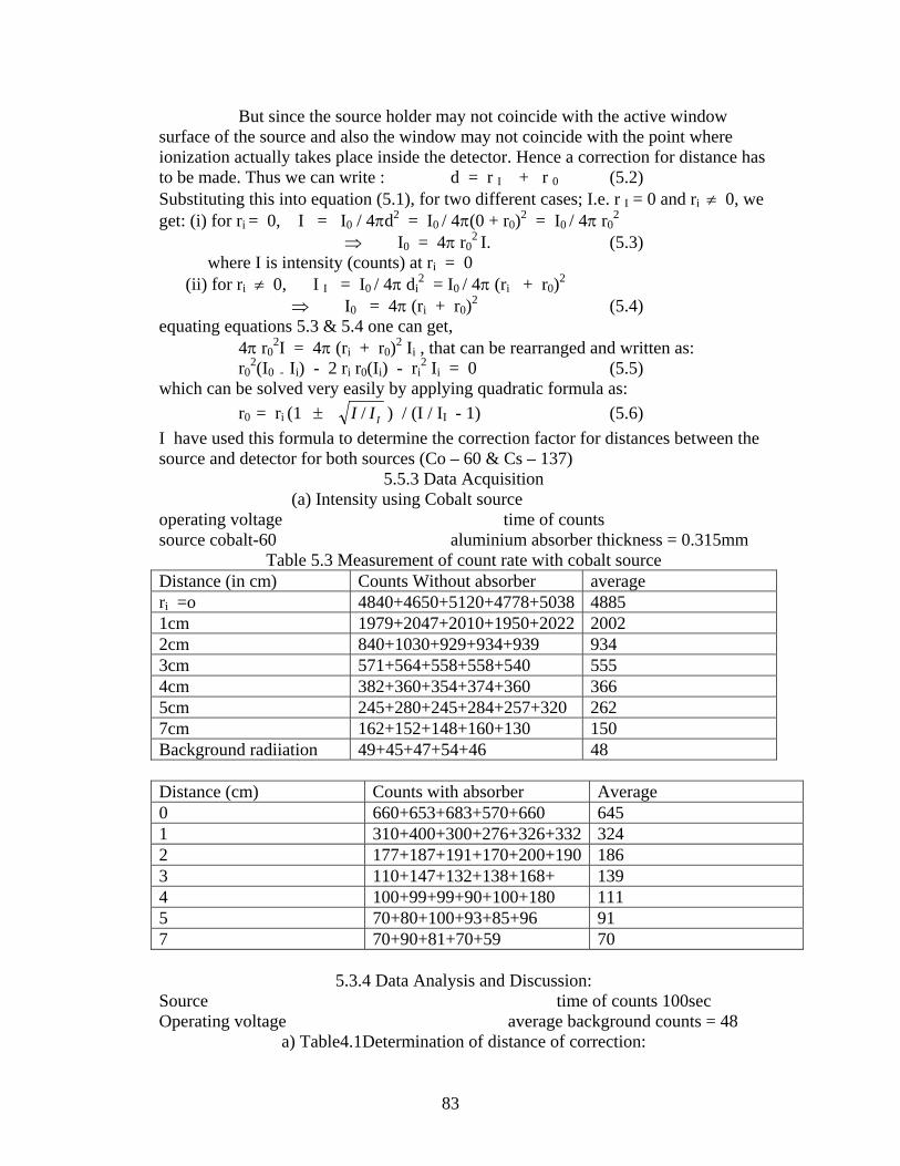
83
But since the source holder may not coincide with the active window surface of the source and also the window may not coincide with the point where ionization actually takes place inside the detector. Hence a correction for distance has to be made. Thus we can write : d = r I + r 0 (5.2) Substituting this into equation (5.1), for two different cases; I.e. r I = 0 and ri ≠ 0, we get: (i) for ri = 0, I = I0 / 4πd2 = I0 / 4π(0 + r0)2 = I0 / 4π r0
2 ⇒ I0 = 4π r0
2 I. (5.3) where I is intensity (counts) at ri = 0 (ii) for ri ≠ 0, I I = I0 / 4π di
2 = I0 / 4π (ri + r0)2 ⇒ I0 = 4π (ri + r0)2 (5.4) equating equations 5.3 & 5.4 one can get, 4π r0
2I = 4π (ri + r0)2 Ii , that can be rearranged and written as: r0
2(I0 - Ii) - 2 ri r0(Ii) - ri2 Ii = 0 (5.5)
which can be solved very easily by applying quadratic formula as: r0 = ri (1 ± III / ) / (I / II - 1) (5.6) I have used this formula to determine the correction factor for distances between the source and detector for both sources (Co – 60 & Cs – 137)
5.5.3 Data Acquisition (a) Intensity using Cobalt source operating voltage time of counts source cobalt-60 aluminium absorber thickness = 0.315mm
Table 5.3 Measurement of count rate with cobalt source Distance (in cm) Counts Without absorber average ri =o 4840+4650+5120+4778+5038 4885 1cm 1979+2047+2010+1950+2022 2002 2cm 840+1030+929+934+939 934 3cm 571+564+558+558+540 555 4cm 382+360+354+374+360 366 5cm 245+280+245+284+257+320 262 7cm 162+152+148+160+130 150 Background radiiation 49+45+47+54+46 48 Distance (cm) Counts with absorber Average 0 660+653+683+570+660 645 1 310+400+300+276+326+332 324 2 177+187+191+170+200+190 186 3 110+147+132+138+168+ 139 4 100+99+99+90+100+180 111 5 70+80+100+93+85+96 91 7 70+90+81+70+59 70
5.3.4 Data Analysis and Discussion: Source time of counts 100sec Operating voltage average background counts = 48
a) Table4.1Determination of distance of correction:
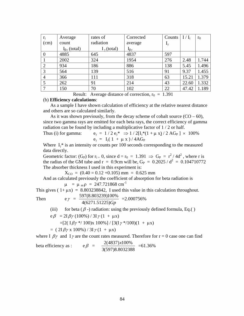
84
ri (cm)
Average count Iβγ (total)
rates of radiation I γ (total)
Corrected average Iβγ
Counts Iγ
I / Ii
r0
0 4885 645 4837 597 1 2002 324 1954 276 2.48 1.7442 934 186 886 138 5.45 1.4963 564 139 516 91 9.37 1.4554 366 111 318 63 15.21 1.3795 262 91 214 43 22.60 1.3327 150 70 102 22 47.42 1.189 Result: Average distance of correction, r0 = 1.391 (b) Efficiency calculations: As a sample I have shown calculation of efficiency at the relative nearest distance and others are so calculated similarly. As it was shown previously, from the decay scheme of cobalt source (CO – 60), since two gamma rays are emitted for each beta rays, the correct efficiency of gamma radiation can be found by including a multiplicative factor of 1 / 2 or half. Thus (i) for gamma: eγ = 1 / 2 eγ* ⇒ 1 / 2[Iγ*(1 + μ x) / 2 AGP ] × 100% eγ = Iγ( 1 + μ x ) / 4AGP Where Iγ* is an intensity or counts per 100 seconds corresponding to the measured data directly. Geometric factor: (GP) for ri = 0, since d = r0 = 1.391 ⇒ GP = r2 / 4d2 , where r is the radius of the GM tube and r = 0.9cm will be, GP = 0.2025 / d2 = 0.104710772 The absorber thickness I used in this experiment is: XCO = (0.40 = 0.12 +0.105) mm = 0.625 mm And as calculated previously the coefficient of absorption for beta radiation is
μ = μ m ρ = 247.721868 cm-1 This gives ( 1+ μx) = 8.803238842, I used this value in this calculation throughout.
Then eγ = Gp)51225.6271(4
%100)803239.8(597 =2.000756%
(iii) for beta ( β -) radiation: using the previously defined formula, Eq.( ) e β = 2I βγ (100%) / 3Iγ (1 + μx) =[2( I βγ */ 100)x 100%] / [3(Iγ */100)(1 + μx) = ( 2I βγ x 100%) / 3Iγ (1 + μx)
where I βγ and Iγ are the count rates measured. Therefore for r = 0 case one can find
beta efficiency as : e β = 8032388.8)597(3
%100)4837(2 x =61.36%
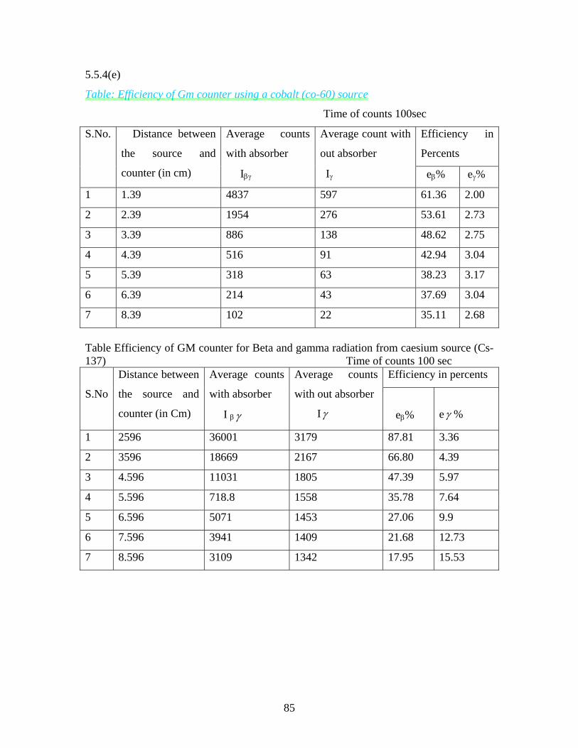
85
5.5.4(e)
Table: Efficiency of Gm counter using a cobalt (co-60) source
Time of counts 100sec
Efficiency in
Percents
S.No. Distance between
the source and
counter (in cm)
Average counts
with absorber
Iβγ
Average count with
out absorber
Iγ eβ% eγ%
1 1.39 4837 597 61.36 2.00
2 2.39 1954 276 53.61 2.73
3 3.39 886 138 48.62 2.75
4 4.39 516 91 42.94 3.04
5 5.39 318 63 38.23 3.17
6 6.39 214 43 37.69 3.04
7 8.39 102 22 35.11 2.68
Table Efficiency of GM counter for Beta and gamma radiation from caesium source (Cs-137) Time of counts 100 sec
Efficiency in percents
S.No
Distance between
the source and
counter (in Cm)
Average counts
with absorber
I β γ
Average counts
with out absorber
Iγ
eβ%
eγ %
1 2596 36001 3179 87.81 3.36
2 3596 18669 2167 66.80 4.39
3 4.596 11031 1805 47.39 5.97
4 5.596 718.8 1558 35.78 7.64
5 6.596 5071 1453 27.06 9.9
6 7.596 3941 1409 21.68 12.73
7 8.596 3109 1342 17.95 15.53
86
5.5.5 Results and Discussion
Result: The efficiency of GM. counter for beta and gamma rays have been calculated by
placing the source at different distances from the detector. The efficiencies are shown in
the above table.
It is possible to consider three basic cases of interest based on the results obtained. They
are (i) The nearest distance case, (ii) Efficiency variation with distance and
(iii) Efficiency comparison of the two sources. I will discuss this as follows:
(A) Efficiency at the nearest point:
From the results obtained for beta and gamma radiation, when there sources are placed at
the closest distance from the detector (GM-tube), it is clear that efficiency for charged
particle (Beta-rays) is the highest while that for gamma radiation (neutral gamma-rays) is
the lowest. This has shown that efficiency for beta (Beta- radiation) to be about 88% and
that for gamma about 2%, which is an interacting result. Further, one can think of the
possibility for better result by putting the source closer to the detector.
Theoretically, the efficiency of GM-Counter is 100% for ionizing particles, but it depends
on penetrating power of charged particle and absorption coefficient of the medium.
Hence efficiency of beta ( β ) is less than 100% because it is not mono energetic as
neutrinos are also emitted along with Beta radiation. The Beta- energies, 0.31 Mev for
cobalt source (Co- 60) and 0.51Mev for caesium source are the maximum possible (end
point) energies in the energy spectrum. Therefore there is a possibility for some betas to
be absorbed and as well to be blocked at the end window of the GM tube. Here the
prevailing interaction responsible for the detection process is in-elastic scattering that can
produce excitation and ionization and also there is a room for elastic scattering for betas
to return back. Any way the result has proved that GM counter is a very good detector for
charged particles.
(B) Efficiency variation with distance: The second basic fact is the variation of
efficiency with distance of separation. The result shows that the efficiency of beta
radiation decreases with increasing distance, where as that of γ -radiation rather
increases. This is most probably due to the following reasons
87
a)Beta- radiation decreases as distance increases because; (i) since it can be
absorbed by the air medium , the beta rays from the cobalt source can not enter the
counter as it is only 0.31 Mev only.
(ii) Due to solid angle for which no correction is applied the results can be as
observed. As distance increases, the intensity reaching the active volume of the
detector decreases since the solid angle between source and detector decreases. The
geometric factor takes into account the variation of intensity with distance form the
source only and it depends on geometry of this source and detector. Thus as distance
increases we are losing a number of betas.
(ii) Since we have not used collimator to direct the radiation toward the detector (end window) this is an expected result.
(a) For gamma radiation on the other hand is relatively it increasing unlike beta
radiation. γ - radiation is not absorbed in air and as well it is not affected by
window of the detector even. But here it is observed that the efficiency of γ -
radiation is increasing (relatively) with increasing distance. This can be due to the
following reason. From the very nature of the gas filled detector, γ -radiation does
not interact with argon gas, but interacts with copper cathode. Since γ -radiation
is energetic at lower distances (when nearer to detector). The interaction
probability with cathode is relatively small and the rest pass without interaction.
As distance increases the relative number of γ - rays that can interact with the
cathode (which is the cylindrical part found at the side of the detector increases.
Then the increased interaction. Hence, here as angle subtended (should angle)
decreases the efficiency increases due to the increased interaction probability.
(C) The third basic fact that I want to touch is the effect of using two different sources.
The nature of the energy emitted by the radioactive source is also responsible for the
relative changes in efficiency of the two sources. This also proves that Beta rays coming
from cobalt (Co-60) are weaker as compared to that coming from cesium (Cs- 137).
Efficiency comparison for gamma –rays of the two sources show that γ -efficiency is
relatively higher for cesium and lower for cobalt. For cesium it increases with increasing
distance relatively at higher rate as compared to that of cobalt, which is almost in
88
dependent of distance. This is indication of energetic gamma rays coming from cobalt
source and relatively weaker γ -rays from cesium.
The effect of using two different sources reinforces the same fact that GM counter efficiency is low for unchanged (γ - rays) radiation and high for changed particle radiation. This also proves that GM-is not a good detector for γ - radiation as such. However, one can conclude that we have different efficiencies (relatively) but showing the same pattern both for cobalt and caesium
5.5.6 Sources of Error The sources of error can be many. But the prevailing sources of error in this
experiment are: (1) Instrumental error=The Gm counter that I used was old, that has been used for
long time. Thus as time passes its detection efficiency can decrease.
(2) The problem of the sources used as radiation sources: The sources used in this
experiment are not point sources as such, where the relations used are valid
specially for point sources. Therefore, the fact that the sources are extended
sources can add to the error.
Also the sources have been used for long time and their activities are relatively low
.In addition the fact that exact manufacture date is not known can contribute to the
error.
(3) Personal error-There is inherent error in distance measurement and adjustment, as
it is difficult to measure distance using local ruler. The measurement of absorber
thickness using micrometers cannot be 100% accurate. Specially as distances
increase putting the source directly below the detector (window) and accurate
distance measurement is difficult.
(4) Absorbers: There is a problem in using absorbers since aluminum absorbers of the
right thickness for this experiment are not available .As a result I have used
combination of absorber whose thickness is more than the required. Using
absorber thickness more than the required can contribute to the error in this
experiment.
5. 5.6. .conclusion.
Radiation detectors are used to detect the radiation that cannot be sensed by our sense
organs. As a detector in this project I used a Gas filled detector, which is called GM-
counter. This is the most common detector and it can be used for the detection of charged
89
radiation & uncharged radiations In this experiment the detection of beta and gamma
radiations has been made. Not only detection but also I have succeeded in determining
the efficiency of GM counter.
Despite all the limitations mentioned as sources of error, the experimental result
achieved is very interesting. The fact that I used an old GM tube that has worked for a
long time and also sources that have been used long since also can contribute to the lesser
accuracy. Of course I have tried my best to be as accurate as possible. Therefore the
achievement of this work has shown: That
(i) Efficiency for beta radiation is about 88%, where it is expected to be around
100% and
(ii) For gamma radiation 2% where it is expected to be around 1%.
Based on the achieved result the following conclusions can be made:.
(1) It is possible to use GM counter as a charged radiation (Beta radiation) detector as it
has high efficiency for detection.
(2) It can also be used to detect unchanged radiation, such as gamma radiation though its
efficiency is low.
(3) Beta radiation is weak and can be absorbed very easily as it can be blocked using thin
aluminum.
(4) Gamma radiation is energetic radiation that can produce low ionization that can not be
absorbed easily. it can be blocked by using lead and thick absorbers.
5.5.7 Recommendations:
Of course, we have as a scintillation detector-sodium iodide (NaI) detector, as a solid
state (semiconductor) detector Highly pure Germanium (HPGe) detector ,and as a gas
filled detector –GM counter in our nuclear physics lab (AAU).Which are very helpful for
different nuclear experiments. I see that there is a possibility of continuing in this field.
There is a good ground for this field to grow. But this needs due attention of
furnishing the laboratory with necessary equipment. .I have observed that there are no
spare parts for the detectors and also there are no reserve detectors if it happened that
they are damaged. If due attention is given to this field (Nuclear physics), it can
contribute to the development of our country. Recently manufactured radio active source
of differently types and different laboratory equipments at least two or more in number
90
for each case should be there since nuclear physics can be used for the benefit of man
kind. The presence of detectors as a sample in our lab is good but not enough. It needs
due attention of the concerned body since this field has wide application.
Specially to solve the crucial energy problem of finding replaceable energy source, the
knowledge of nuclear physics and hence radiation as a whole is important. The
knowledge of nucleus and then the properties of materials can play role in energy
conversion and looking for alternate energy sources such as sun light it self. Physics as a
whole and also nuclear physics in particular can play its role in this aspect if planned
activity is made in this sphere.
91
References 1. Mukhn, K.N (1987). Experimental Nuclear physics. Vol 1, Mir publishers,
Moscow, 1987. 2. Harrison, A.W (1966). Intermediate Atomic and Nuclear physics. London,
Macmillan 3. Halliday, D. (1958). Introductory Nuclear physics, second edition. Tokyo, John
Wiley & Sons Inc. 4. Hoisington, D.B (1959). Nucleonics Fundamentals, Newyork, MICGRAW- HILL
BOOK Company Inc. 5. Beiser, A. (1981). Concepts of Modern physics, third ed., MCGRAW- HILL
International Book Company. 6. Klimov, A. (1975). Nuclear physics and Nuclear Reactors, Moscow, Mir
publishers. 7. Harald, A.E (1971). Introduction to Atomic physics, Addison Wesley publishing
company. 8. Preston, M.A, Physics of the Nucleus. 9. Singru, R.M (1974). Introduction to Experimental Nuclear physics, Wiley Eastern
limited. 10. Yuan,L.C.L ,(1961). Methods of Experimental physics vol 5A, Newyork,
Academic press. 11. Knoll, G.F, Radiation Detection and Measurement, Third Edition, Newyork, John
Wiley & sons Inc. 12. Kaplan, I., (1963) Nuclear physics, Addison Wesley, 2nd edition. 13. Tiwari, P.N, (1974). Fundamentals of Nuclear science. New Delhi, Wiley Eastern
Limited. 14. Dearnaley, G. Northrop, D.C, Semiconductor counters for Nuclear radiations 15. Taylor, J.R, Modern physics for Scientists and Engineers

92
Related Documents


![HR - Runes & Radiations [Edited]](https://static.cupdf.com/doc/110x72/577ce7301a28abf103948b15/hr-runes-radiations-edited.jpg)