ORIGINAL ARTICLE Effects of welding wire and torch weaving on GMAW of S355MC and AISI 304L dissimilar welds H. Tasalloti & P. Kah & J. Martikainen Received: 3 June 2013 /Accepted: 10 November 2013 /Published online: 22 November 2013 # Springer-Verlag London 2013 Abstract Dissimilar welding of austenitic stainless steel (ASS) to low-alloy structural steel is widely used in the power generation industry. The formation of brittle martensite and hot cracking susceptibility in the single-phase austenite mi- crostructure are the main concerns related to the metallurgy of this kind of weld. This study investigates the effect of different welding wires and the weaving technique on the quality, microstructure and microhardness of fillet weld joints between AISI 304L austenitic stainless steel and S355MC low-alloy structural steel. Using robotised synergic gas metal arc welding (GMAW), three different filler wires were used to weld specimens with and without weaving. The macro- sections of the fillet welds were inspected and the dilution rates and ferrite numbers (FN) measured. The microstructure was also inspected and microhardness values recorded. Po- rosity was discerned in two weld samples made with the use of weave beads. The measured FNs for all the weldments were very close to estimations from the Schaeffler diagram. The formation of a narrow martensitic band on the ferritic side of the weld metal was detected for most of the specimens. It is concluded that weaving decreased the dilution rate and in- creased the FN. However, no obvious effect on the micro- structure and hardness as a result of using the weaving tech- nique was noticed. Keywords Dissimilar metal welding . GMAW . Torch weaving . Interface properties . Microstructure . AISI 304L stainless steel . S355MC structural steel 1 Introduction The combination of austenitic stainless steel (ASS) and low- alloy structural steel presents favourable mechanical proper- ties, formability, weldability, resistance to stress corrosion cracking and other forms of corrosion [1], along with fairly cost-effective [2, 3] manufacturing methods [4, 5]. Due to these advantageous characteristics, such combinations of metals are extensively utilised in the power generation indus- try [6], as well as in petrochemical plants and architecture [7–9]. A range of metallurgical concerns are present in the dis- similar welding (DMW) of ASS to low-alloy structural steel. Martensite formation on the ferritic side of the DMW interface and the risk of hot cracking in the fully austenite microstruc- ture on the austenitic side are the main concerns in this kind of weld [10]. Depending on the chemical composition of the weld metal (WM), the growth of brittle martensite can take place both in the weld and in the heat-affected zone (HAZ) [9]. The ferrite number (FN) is another critical aspect in the DMW of ASS to low-alloy structural steel. Ferrite can be beneficial in reducing the tendency of cracking in the weld. However, excessive amounts of ferrite have a detrimental effect on corrosion resistance and the mechanical properties [11]. The amount of ferrite can be controlled by careful regulation of the filler metal composition and substrate dilution [12]. The aim is to obtain stable austenite with a small amount of ferrite, a microstructure that reduces the chance of weld solidification cracking [2]. Approximate microstructural prediction from the Schaeffler diagram can be made for DMW of ASS and low- alloy structural steels [2]. Solidification behaviour and ferrite content can be affected by the welding process and welding parameters due to variations in the amount of heat input and the solidification speed [13]. For GMAW welding of ASS and ferritic steel, the effect of torch weaving in correlation with filler material on the H. Tasalloti : P. Kah (*) : J. Martikainen Lappeenranta University of Technology, P.O. Box 20, 53851 Lappeenranta, Finland e-mail: [email protected] Int J Adv Manuf Technol (2014) 71:197–205 DOI 10.1007/s00170-013-5484-x

Welcome message from author
This document is posted to help you gain knowledge. Please leave a comment to let me know what you think about it! Share it to your friends and learn new things together.
Transcript

ORIGINAL ARTICLE
Effects of welding wire and torch weaving on GMAWof S355MC and AISI 304L dissimilar welds
H. Tasalloti & P. Kah & J. Martikainen
Received: 3 June 2013 /Accepted: 10 November 2013 /Published online: 22 November 2013# Springer-Verlag London 2013
Abstract Dissimilar welding of austenitic stainless steel(ASS) to low-alloy structural steel is widely used in the powergeneration industry. The formation of brittle martensite andhot cracking susceptibility in the single-phase austenite mi-crostructure are the main concerns related to the metallurgy ofthis kind of weld. This study investigates the effect of differentwelding wires and the weaving technique on the quality,microstructure and microhardness of fillet weld joints betweenAISI 304L austenitic stainless steel and S355MC low-alloystructural steel. Using robotised synergic gas metal arcwelding (GMAW), three different filler wires were used toweld specimens with and without weaving. The macro-sections of the fillet welds were inspected and the dilutionrates and ferrite numbers (FN) measured. The microstructurewas also inspected and microhardness values recorded. Po-rosity was discerned in twoweld samples madewith the use ofweave beads. The measured FNs for all the weldments werevery close to estimations from the Schaeffler diagram. Theformation of a narrow martensitic band on the ferritic side ofthe weld metal was detected for most of the specimens. It isconcluded that weaving decreased the dilution rate and in-creased the FN. However, no obvious effect on the micro-structure and hardness as a result of using the weaving tech-nique was noticed.
Keywords Dissimilar metal welding . GMAW . Torchweaving . Interface properties .Microstructure . AISI 304Lstainless steel . S355MC structural steel
1 Introduction
The combination of austenitic stainless steel (ASS) and low-alloy structural steel presents favourable mechanical proper-ties, formability, weldability, resistance to stress corrosioncracking and other forms of corrosion [1], along with fairlycost-effective [2, 3] manufacturing methods [4, 5]. Due tothese advantageous characteristics, such combinations ofmetals are extensively utilised in the power generation indus-try [6], as well as in petrochemical plants and architecture[7–9].
A range of metallurgical concerns are present in the dis-similar welding (DMW) of ASS to low-alloy structural steel.Martensite formation on the ferritic side of the DMW interfaceand the risk of hot cracking in the fully austenite microstruc-ture on the austenitic side are the main concerns in this kind ofweld [10]. Depending on the chemical composition of theweld metal (WM), the growth of brittle martensite can takeplace both in the weld and in the heat-affected zone (HAZ) [9].The ferrite number (FN) is another critical aspect in the DMWof ASS to low-alloy structural steel. Ferrite can be beneficialin reducing the tendency of cracking in the weld. However,excessive amounts of ferrite have a detrimental effect oncorrosion resistance and the mechanical properties [11]. Theamount of ferrite can be controlled by careful regulation of thefiller metal composition and substrate dilution [12]. The aim isto obtain stable austenite with a small amount of ferrite, amicrostructure that reduces the chance of weld solidificationcracking [2]. Approximate microstructural prediction from theSchaeffler diagram can be made for DMW of ASS and low-alloy structural steels [2]. Solidification behaviour and ferritecontent can be affected by the welding process and weldingparameters due to variations in the amount of heat input andthe solidification speed [13].
For GMAWwelding of ASS and ferritic steel, the effect oftorch weaving in correlation with filler material on the
H. Tasalloti : P. Kah (*) : J. MartikainenLappeenranta University of Technology, P.O. Box 20,53851 Lappeenranta, Finlande-mail: [email protected]
Int J Adv Manuf Technol (2014) 71:197–205DOI 10.1007/s00170-013-5484-x

dissimilar weld has not been explicitly investigated yet. Thiswork concentrates on evaluating the effect of differentwelding wire compositions and implementation of the weav-ing technique on the DMW of AISI 304L to S355MC low-alloy structural steel. Another objective of this study is tocompare the experimental results with theoretical approachessuch as the Schaeffler diagram. For these purposes, a filletweld was made between the two base metals (BMs) usingrobotised GMAW with a synergic power control. Three dif-ferent filler wires were used for fabricating the fillet welds bymeans of weave and stringer bead for each wire separately.The macro-sections of the weld samples were inspected forpossible defects. The penetration measurement and dilutioncalculation was done for the weld samples prepared for me-tallographic examination. FN was measured using magneticinduction method. An optical microscope was used to inspectthe microstructures of the weld samples around the fusionboundary on both AISI304 and S355MC sides. The hardnessvariations on the cross-section of the dissimilar welds wereobtained for the weld and base metals to find evidence for thepresence of different phases.
2 Experimental procedure
Two dissimilar materials, S355MC structural steel and AISI304L ASS, were used in fabricating the fillet weld joint in thisexperiment. The BMs (5-mm thick) were welded with threedifferent filler wires, namely Esab OK Autrod 16.54(EOA16.54 ), Esab OK Autrod 16.55 (EOA16.55 ) and ElgaCromarod 316LSi (EC316LSi). These three wires were usedto weld the base materials with a robotised GMAW process.The material specifications and the process parameters arepresented in Tables 1 and 2. Using each filler wire with eithera stringer or weave bead, two separate single pass fillet welds,
300 mm in length, were made on one side of the prepared T-joint assemblies. Weaving frequency was 3 Hz, with ampli-tude of 1.5 mm from the centre of the weld. Amixture of 98%Ar+2 % CO2 with a constant flow rate of 16 l/min was usedfor welding all the samples. Specimens of 25 mm in lengthwere cut out from the middle of the weld. The cross-sectionsof the weld specimens were ground and polished using 1-μmdiamond paste. Glyceregia etchant (15 ml glycerol, 10 ml HCland 5 ml HNO3) was used to expose both the macro- and themicrostructure for metallographic inspection. In this study,WMs are denominated with the last number of the buildingfiller wire code plus “W” when weaving was used; for in-stance, 16.54 and 16.54W indicate a WM made fromEOA16.54 filler wire without and with weaving, respectively.
3 Results and discussion
3.1 Visual inspection
The metallographically prepared samples were inspectedusing a stereo-microscope. The macro-sections of the weldsamples are shown in Fig. 1a–f. The leg size, convexity andmaximum penetration on each side of the welds are marked inthe figure. The cross-sections of the weld samples displaythorough fusion between the WM and the substrates and asufficient amount of penetration.
It can be seen from Fig. 1 that penetration is superior on theaustenitic side. For S355MC, penetration ranges from 1.1 to2.2 mm, and for AISI 304L from 2.4 to 2.7 mm. The differ-ence may be due to the lower melting point of AISI 304L (∼1,450 °C compared to ∼154 °C) [14]. Figure 1 also shows thatpenetration on the S355MC side decreases when using weav-ing, whereas it increases on the AISI 304L side. The greaterpenetration is possibly due to heat accumulation on the
Table 1 Chemical composition(wt.%) of base materials andwelding wires
C Cr Mn Ni P S Si N Al Mo Cu
AISI 304L 0.025 18 1.57 8.1 0.033 0.002 0.4 0.044 – – –
S355MC 0.12 – 1.5 – 0.02 0.015 0.03 – 0.015 – –
EOA16.54 <0.03 21.5 1.4 15.0 – – 0.4 – – 2.7 –
EOA16.55 <0.02 20.5 1.7 25.0 – – 0.4 – – 4.5 1.4
EC316LSi 0.02 18.5 0.7 12.0 0.02 0.02 0.8 – – 2.7 0.1
Table 2 Welding parameters fordissimilar welding: wire diameter(Ø), wire feed speed (VW),welding current (I), welding volt-age (U), travel speed (v) and heatinput per unit length of weld (Q)
Wire Ø (mm) vw (m/min) Stick-out (mm) I (A) U (V) v (mm/s) Q (kJ/mm)
EOA16.54 1.2 11.2 20 260 24.5 8.4 0.61
EOA16.55 1 11.4 17 227 24 7.5 0.58
EC316LSi 1 11.4 17 227 24 7.5 0.58
198 Int J Adv Manuf Technol (2014) 71:197–205
austenitic side because of its lower degree of heat conductiv-ity. In contrast, the decreased penetration on the S355MC sideis probably a result of faster heat dissipation due to weavingand the higher heat conductivity of S355MC. The maximummeasured convexity, as can be seen in Fig. 1b, was 0.75 mmfor 16.54W. For 16.55 and 316LSi , undercut with a depth of0.4 and 0.2 mm, respectively, was detected, which can be seenin Fig. 1c, e. Yongjae et al. [15] have shown through theirnumerical method that the heat input concentrates at theweaving end, which can cause undercut. However, such aresult was not observed in this experiment. Minor undercutswere also detected in the stinger welds.
Porosity was detected in 16.54W and 316LSiW, observablein Fig. 2a, b. The diameter of the pores is about 50 μm for thesmallest one and 200 μm for the biggest one, found in 16.54W.The pores were situated at the root of the weld. Both sampleswere made with weaving and the porosity may result from thelower efficiency of the shielding gas when weaving is used[16].
3.2 Dilution rate
Dilution levels were calculated measuring the geometriccross-sectional areas of the deposited filler metal and meltedBMs, presented in Table 3. In Fig. 3, the overall dilution rate
ofWMs by BMs are shown and compared. From this figure, itis obvious that dilution is less when using the weaving tech-nique compared to the stringer deposit. This is consistent withexpectations since it is known that weaving reduces the dilu-tion rate in BMs [17, 18]. Lower dilution, especiallyconcerning S355MC, is very important. If the weld is heavilydiluted by the structural steel, it may solidify as fully austeniteor primary austenite because of insufficient ferrite potential inthe filler metal, causing an increase in the potential forsolidification cracking [2].
3.3 Schaeffler diagram
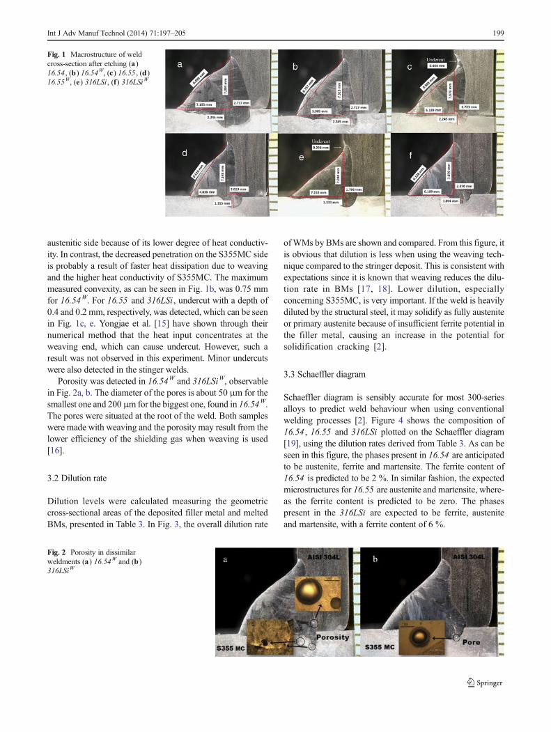
Schaeffler diagram is sensibly accurate for most 300-seriesalloys to predict weld behaviour when using conventionalwelding processes [2]. Figure 4 shows the composition of16.54 , 16.55 and 316LSi plotted on the Schaeffler diagram[19], using the dilution rates derived from Table 3. As can beseen in this figure, the phases present in 16.54 are anticipatedto be austenite, ferrite and martensite. The ferrite content of16.54 is predicted to be 2 %. In similar fashion, the expectedmicrostructures for 16.55 are austenite and martensite, where-as the ferrite content is predicted to be zero. The phasespresent in the 316LSi are expected to be ferrite, austeniteand martensite, with a ferrite content of 6 %.
Fig. 1 Macrostructure of weldcross-section after etching (a)16.54 , (b) 16.54W, (c) 16.55 , (d)16.55W, (e) 316LSi, (f) 316LSiW
Fig. 2 Porosity in dissimilarweldments (a) 16.54W and (b)316LSiW
Int J Adv Manuf Technol (2014) 71:197–205 199

3.4 Ferrite number
The FN was volumetrically measured using a standard ferritescope device. The measurement was done for five selectedpoints located along the sectioned WM and around the weldaxis. The maximum, minimum and average values recordedfrom the measurements are shown in Fig. 5. The figure alsopresents a comparison of the recorded FNs and the predictedferrite content derived from the Schaeffler diagram.
The measurements for 16.55 and 16.55W show the FN tobe near to zero, consistent with predictions from the Schaefflerdiagram. This is due to the high Ni contents of EOA16.55 , astrong austenite stabiliser element. Figure 5 shows that for16.55 , 16.55W and 316LSiW, the measured FNs are very closeto those predicted by the Schaeffler diagram. For 16.54 ,16.54W, the measured FNs are higher than predicted. Thismay be due to the variations in the welding parameters.Another noticeable point of interest in Fig. 5 is the higherFN found in weldments made using the same filler wires butwith the weaving method. One possible explanation may bethat faster solidification occurs, since weaving spreads theheat out from the arc and deposits metal over a less concen-trated area [15, 18]. The faster the solidification, the less ferrite
can be transformed to austenite in the primary ferritic solidi-fication mode.
3.5 Microstructure
The connection between solidification behaviour and Creq/Nieq was established by Suutala and Moisio [13, 20]. Figure 6shows the composition of the welding wires plotted on theSuutala and Moisio diagram [13, 20] using the shown coeffi-cients of Nieq and Creq. The Nieq and Creq delineate thesolidification mode satisfactorily for most conventional 300-series alloys welded under normal arc-welding conditions[13]. This diagram outlines the four solidification types asfollows: single-phase austenite (“A”), primarily austeniticwith a small fraction of eutectic ferrite (“AF”), primary ferritewith the peritectic/eutectic solidification of austenite (“FA”)and single-phase ferrite (“F”) [13]. From this diagram, theexpected solidification mode for EOA16.55 is type “A” andfor both EOA16.54 and EC316LSi , it is “FA.”
Figures 7, 8, 9, 10, 11 and 12 show optical micrographs ofthe weld between S355MC and AISI 304L made with thedifferent welding wires. In these figures, the bright zones areaustenite and the dark zones ferrite, as revealed by the etchingfor the AISI 304L and welds. Figure 7a, b illustrates themicrostructure between 16.54 and the austenitic and ferriticBMs, respectively. Figure 7a shows type “AF” solidificationduring which a small amount of second-phase ferrite, furtheraway from the fusion line, has formed. The microstructure isquite similar to that of the single-phase austenite, except thatferrite particles are present at the cell boundaries. Some solid-state transformation has also occurred, leaving isolatedspheres of ferrite at the cell or dendrite walls [21]. The pres-ence of ferrite stringers in some of the austenite grains withinthe substrate close to the HAZ can be seen in Fig. 7a. Theferrite stringers have expanded and grown in places close tothe fusion boundary. This expansion is most likely due torapid cooling after the formation of delta ferrite during theheating cycle, which results in a higher amount of ferrite beingretained [22].
Figure 7b shows a type “FA” solidified alloy. Adjacent tothe fusion line, skeletal (or vermicular) structures of ferrite canbe seen. Skeletal ferrite forms when weld cooling rates aremoderate and/or when Creq/Nieq is low but still within the“FA” range (see Fig. 6) [21]. Figure 7b also reveals ferritelocated at the cell cores in intercellular austenite [21]. Duringsolidification, the development of the austenite phase con-sumes the ferrite until the ferrite is sufficiently enriched inferrite-promoting elements and depleted in austenite-promoting elements, stabilising the ferrite at lower tempera-tures [2]. The presence of a martensite layer adjacent to theweld interface, where the composition varies continuouslyfrom that of the ferritic steel to that of the austenitic WM[23], was also detected and is shown in Fig. 7b. At the fusion
Table 3 Dilution percentage of FMs and BMs in theWM and the overalldilution rate of the WM by substrates
Classification Wire S355MC AISI 304 Overall
16.54 66.77 16.14 17.09 33.23
16.54 W 72.28 12.43 15.28 27.72
16.55 68.66 9.83 21.51 31.34
16.55 W 71.37 8.32 20.31 28.63
316 LSi 71.12 10.94 17.94 28.88
316 LSi W 74.34 6.93 18.73 25.66
Fig. 3 Overall dilution of the deposited weld by substrates
200 Int J Adv Manuf Technol (2014) 71:197–205
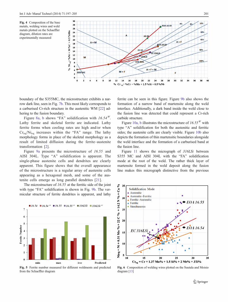
boundary of the S355MC, the microstructure exhibits a nar-row dark line, seen in Fig. 7b. This most likely corresponds toa carburised Cr-rich structure in the austenitic WM [22] ad-hering to the fusion boundary.
Figure 8a, b shows “FA” solidification with 16.54W.Lathy ferrite and skeletal ferrite are indicated. Lathyferrite forms when cooling rates are high and/or whenCreq/Nieq increases within the “FA” range. The lathymorphology forms in place of the skeletal morphology as aresult of limited diffusion during the ferrite–austenitetransformation [2].
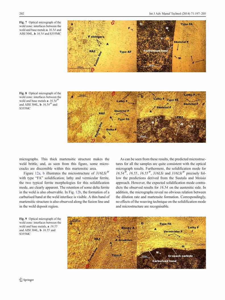
Figure 9a presents the microstructure of 16.55 andAISI 304L. Type “A” solidification is apparent. Thesingle-phase austenite cells and dendrites are clearlyapparent. This figure shows that the overall appearanceof the microstructure is a regular array of austenite cellsappearing as a hexagonal mesh, and some of the aus-tenite cells emerge as long parallel dendrites [21].
The microstructure of 16.55 at the ferritic side of the jointwith type “FA” solidification is shown in Fig. 9b. The ver-micular structure of ferrite dendrites is apparent, and lathy
ferrite can be seen in this figure. Figure 9b also shows theformation of a narrow band of martensite along the weldinterface. Additionally, a dark band inside the weld close tothe fusion line was detected that could represent a Cr-richcarbide structure.
Figure 10a, b illustrates the microstructure of 16.55W withtype “A” solidification for both the austenitic and ferriticsides; the austenite cells are clearly visible. Figure 10b alsodepicts the formation of thin martensitic boundaries alongsidethe weld interface and the formation of a carburised band atthe fusion line.
Figure 11 shows the micrograph of 316LSi betweenS355 MC and AISI 304L with the “FA” solidificationmode at the root of the weld. The rather thick layer ofmartensite formed in the weld deposit along the fusionline makes this micrograph distinctive from the previous
Fig. 4 Composition of the basemetals, welding wires and weldmetals plotted on the Schaefflerdiagram, dilution rates areexperimentally measured
Fig. 5 Ferrite number measured for different weldments and predictedfrom the Schaeffler diagram
Fig. 6 Composition of welding wires plotted on the Suutala and Moisiodiagram [13]
Int J Adv Manuf Technol (2014) 71:197–205 201
micrographs. This thick martensitic structure makes theweld brittle, and, as seen from this figure, some micro-cracks are discernible within this martensitic area.
Figure 12a, b illustrates the microstructure of 316LSiW
with type “FA” solidification; lathy and vermicular ferrite,the two typical ferrite morphologies for this solidificationmode, are clearly apparent. The retention of some delta ferritein the weld is also observable. In Fig. 12b, the formation of acarburised band at the weld interface is visible. A thin band ofmartensitic structure is also observed along the fusion line andin the weld deposit region.
As can be seen from these results, the predicted microstruc-tures for all the samples are quite consistent with the opticalmicrograph results. Furthermore, the solidification mode for16.54W, 16.55 , 16.55W, 316LSi and 316LSiW precisely fol-low the predictions derived from the Suutala and Moisioapproach. However, the expected solidification mode contra-dicts the observed results for 16.54 on the austenitic side. Inaddition, the micrographs reveal no obvious relation betweenthe dilution rate and martensite formation. Correspondingly,no effects of the weaving technique on the solidification modeand microstructure are recognisable.
Fig. 7 Optical micrograph of theweld zone: interfaces between theweld and base metals a 16.54 andAISI 304L, b 16.54 and S355MC
Fig. 8 Optical micrograph of theweld zone: interfaces between theweld and base metals a 16.54W
and AISI 304L, b 16.54W andS355MC
Fig. 9 Optical micrograph of theweld zone: interfaces between theweld and base metals, a 16.55and AISI 304L, b 16.55 andS355MC
202 Int J Adv Manuf Technol (2014) 71:197–205

3.6 Microhardness
The microhardness across the welds was evaluated using adigital Vickers microhardness tester. All hardness indentswere made with 500-g force (4.905 N). Figure 13 comparesthe measured hardness values for welds made with and with-out the use of weaving. As can be seen from the figure,
microhardness nearly follows the same pattern for bothmethods with the same welding wire. For all the samples,the hardness of the weld is inferior to that of the AISI 304Lbase steel, with some exceptional points. This can be attribut-ed to the presence of a higher amount of a strong austenitestabilising element, such as Ni [24].
For 16.54 , 16.54W, 16.55 and 316LSi , there is a large andsharp increase in hardness on the ferritic side adjacent to theweld interface that can be evidence of martensite formation,shown in Fig. 13a, b. These results are consistent with theoptical micrograph findings.
From the predicted ferrite content, microstructure and mea-sured FNs, it can be expected that the hardness values will bethe highest for 316LSi , 16.54 and 16.55 , respectively, bothwith and without the use of weaving. As can be seen inFig. 13, the results are quite consistent with the expectations.
It is claimed that the hardness of the weld metal depends onthe amount of substrate dilution [17]. However, for the weldsamples in this study, no explicit relation between the dilutionratio and hardness values was distinguished that could indi-cate low or non-critical dilution in the weld samples. Never-theless, it seems that the variations in the hardness distributionprofiles are smoother with the weaving method than with thestring weld samples (Fig. 13a, b). This might be due to thelower dilution of the BMs and the more homogeneous com-position of the weld in welds done with weaving.
Fig. 10 Optical micrograph ofthe weld zone: interfaces betweenthe weld and base metals a16.55W and AISI 304L, b 16.55W
and S355MC
Fig. 11 Optical micrograph of the weld zone: interfaces between theweld and base metals, 316LSi and both AISI 304L and S355MC
Fig. 12 Optical micrograph ofthe weld zone: interfaces betweenthe weld and base metals, a316LSiW and AISI 304L, b316LSiW and S355MC
Int J Adv Manuf Technol (2014) 71:197–205 203

4 Conclusions
The present study was conducted to investigate influence ofdifferent welding wires and torch weaving on the quality,microstructure, and microhardness of fillet weld joints be-tween AISI 304L and S355 MC. The following conclusionsare drawn from the present study:
1. Weaving decreased penetration on the S355MC side andincreased penetration on the AISI 304L side. The increasein penetration might be due to heat accumulation on theaustenitic side because of its lower heat conductivity. Incontrast, the decrease in penetration on the S355MC sideis probably a result of faster heat dissipation due to weav-ing and the higher heat conductivity of S355MC.
2. Undercut was detected with 16.55 and 316LSi . No con-nection between weaving and the undercut defect wasfound, and minor undercuts were also detected in thestringer weld.
3. Some pores were found at the weld root of 16.54W and316LSiW. This porosity may be a result of the lowerefficiency of the shielding gas when weaving is used.
4. The measured dilution by the BMs was less when theweaving technique was used compared to the stringerdeposit.
5. In general, the measured FNs are very close to thosepredicted by the Schaeffler diagram, especially for16.55 , 16.55W and 316LSiW. Higher FNs were found inthe weldments made using the weaving method. Thismight be a result of faster solidification.
6. All the weld samples, except for 16.54W, exhibited thepresence of a martensitic region adjacent to the fusionboundary on the ferritic side. The presence of microcrackswas also discerned within the martensitic structure of the316LSi .
7. The predictions derived from the Suutala and Moisioapproach for the solidification mode and the predicted
microstructures from the Schaeffler diagram were quiteconsistent with the optical micrograph results for all thesamples, except for 16.54 on the austenitic side. Noobvious relation between the effects of the weaving tech-nique on the solidification mode and the microstructurewere recognisable from the microstructural analysis.
8. For 16.54 , 16.54W, 16.55 and 316LSi , a sharp increase inhardness was observed on the ferritic side and around thefusion interface, which may reflect the presence of mar-tensite within this region. Based on the microhardnesstest, no explicit relation between the dilution rate andhardness values was distinguished for the weld samples.
References
1. Hasçalik A, Ünal E, Özdemir N (2006) Fatigue behaviour of AISI304 steel to AISI 4340. J Mater Sci 41:3233–3239
2. Lippold JC, Kotecki DJ (2005) Dissimilar welding of stainless steel.In: Welding Metallurgy and Weldability of Stainless Steels. Wiley,New Jersey, pp 287–299
3. Arivazhagan N, Narayanan S, Singh S et al (2012) High temperaturecorrosion studies on friction welded low alloy steel and stainless steelin air and molten salt environment at 650 °C. Mater Des 34:459–468
4. Nascimento MP, Souza RC, Pigatin WL et al (2001) Effects ofsurface treatments on the fatigue strength of AISI 4340 aeronauticalsteel. Int J Fatigue 23:607–618
5. Arivazhagan N, Singh S, Prak S, Reddy G (2011) Investigation onAISI 304 austenitic stainless steel to AISI 4140 low alloy steeldissimilar joints by gas tungsten arc, electron beam and frictionwelding. Mater Des 32(5):3036–3050
6. Shushan SM, Charles EA, Congleton J (1996) The environmentassisted cracking of diffusion bonded stainless steel to carbon steeljoints in an aqueous chloride solution. Corros Sci 38(5):673–686
7. Celik A, Alsaran A (1999) Mechanical and structural properties ofsimilar and dissimilar steel joints. Mater Charact 43(5):311–318
8. Missori S, Koerbe C (1997) Laser beamwelding of austenitic–ferritictransition joints. Welding J 76(3):125–134
9. Fuentes ALG, Salas R, Centeno L et al (2011) Crack growth study ofdissimilar steels (stainless-structural) butt welded unions under cyclicloads. Procedia Eng 10:1917–1923
Fig. 13 Comparison of hardness distribution along the weld metals with a stringer and b weave bead, the vertical dotted lines represent the weldcentrelines
204 Int J Adv Manuf Technol (2014) 71:197–205
10. DuPont JN, Kiser SD, Lippold JC (2009) Dissimilar welding. In:Welding Metallurgy and Weldability of Nickel-Base Alloys. Wiley,New Jersey, pp 327–346
11. ASME Boiler and Pressure Vessel Committee (2007) Code II Part CSpecifications for Welding Rods, Electrodes, and Filler Metals. In:ASME Boiler and Pressure Vessel Code, ASME, p. 92
12. Sun Z, Ion JC (1995) Laser welding of dissimilar metal combina-tions. J Mater Sci 30:4205–4214
13. Brooks JA, Lippold JC (1993) Selection of wrought austenitic stain-less steels. In: ASM Handbook, vol 6. ASM International, pp 456–470
14. Committee of Stainless Steel Producers (1979) Welding of stainlesssteels and other joining methods. AISI, pp 4–6
15. Yongjae K, Sehun R (2005) A study of heat input distribution on thesurface during torch weaving in gas metal arc welding. JSME Int JSer A 48(3):144–150
16. Davies AC (1993) The science and practise of welding. In: ThePractise of Welding, vol 2. Cambridge University Press,Cambridge, pp 37–121
17. Kearns WH (ed) (1984) Welding Handbook, vol 5. AWS, Miami, pp54–253
18. Klimpel A, Lisiecki A, Klimpe AS et al (2007) Abrasive and erosivewear resistance of GMA metal cored wire cermetal deposits.JAMME 28(9):565–572
19. Schaeffler AL (1948) Welding dissimilar metals with stainlesselectrodes. Iron Age 162:72
20. Suutala N, Moisio T (1983) The use of chromium and nickel equiv-alents in considering solidification phenomena in austenitic stainlesssteels. The Metals Society
21. Elmer J, Allen S, Eagar T (1989)Microstructural development duringsolidification of stainless steel alloys. Metall Trans A 20A:1989–2121
22. Naffakh H, Shamanian M, Ashrafizadeh F (2008) Influence of arti-ficial ageing on microstructure and mechanical properties of dissim-ilar welds between 310 stainless steel and INCONEL 657. MetallMater Trans A 39(10):2403–2415
23. Dupont JN, Kusko CS (2007) Technical note: Martensite formationin austenitic/ferritic dissimilar alloy welds. Welding J: pp 51–53
24. Das C, Bhaduri A, Srinivasan G, Shankar Vet al (2009) Selection offiller wire for and effect of auto tempering on the mechanical prop-erties of dissimilar metal joint between 403 and 304L(N) stainlesssteels. J Mater Process Technol 209(3):1428–1438
Int J Adv Manuf Technol (2014) 71:197–205 205
Related Documents