THE SYNERGISTIC EFFECTS OF SLIP RING-BRUSH DESIGN AND MATERIALS N. E. Lewis, S, R. Cole, and E. W, Glossbrenner Poly-Scientific Division Li tton Systems, Inc, 1213 North Main Street Blacksburg, Vi r g i n i a 24060 July 1971 Interim Report for Period March - June 1971 Prepared for GODDARD SPACE FLIGHT CENTER Greenbel t, Mary1and 20771 https://ntrs.nasa.gov/search.jsp?R=19710027190 2020-07-21T15:14:24+00:00Z

Welcome message from author
This document is posted to help you gain knowledge. Please leave a comment to let me know what you think about it! Share it to your friends and learn new things together.
Transcript

THE S Y N E R G I S T I C EFFECTS OF SLIP RING-BRUSH D E S I G N AND MATERIALS
N. E. Lewis, S, R . Cole, and E. W , Glossbrenner
P o l y - S c i e n t i f i c D i v i s i o n
L i t t o n Systems, I n c ,
1213 Nor th Main S t ree t
Blacksburg, V i r g i n i a 24060
Ju ly 1971
I n t e r i m Report for Per iod March - June 1971
Prepared f o r
GODDARD SPACE FLIGHT CENTER
Greenbel t, Mary1 and 20771
https://ntrs.nasa.gov/search.jsp?R=19710027190 2020-07-21T15:14:24+00:00Z
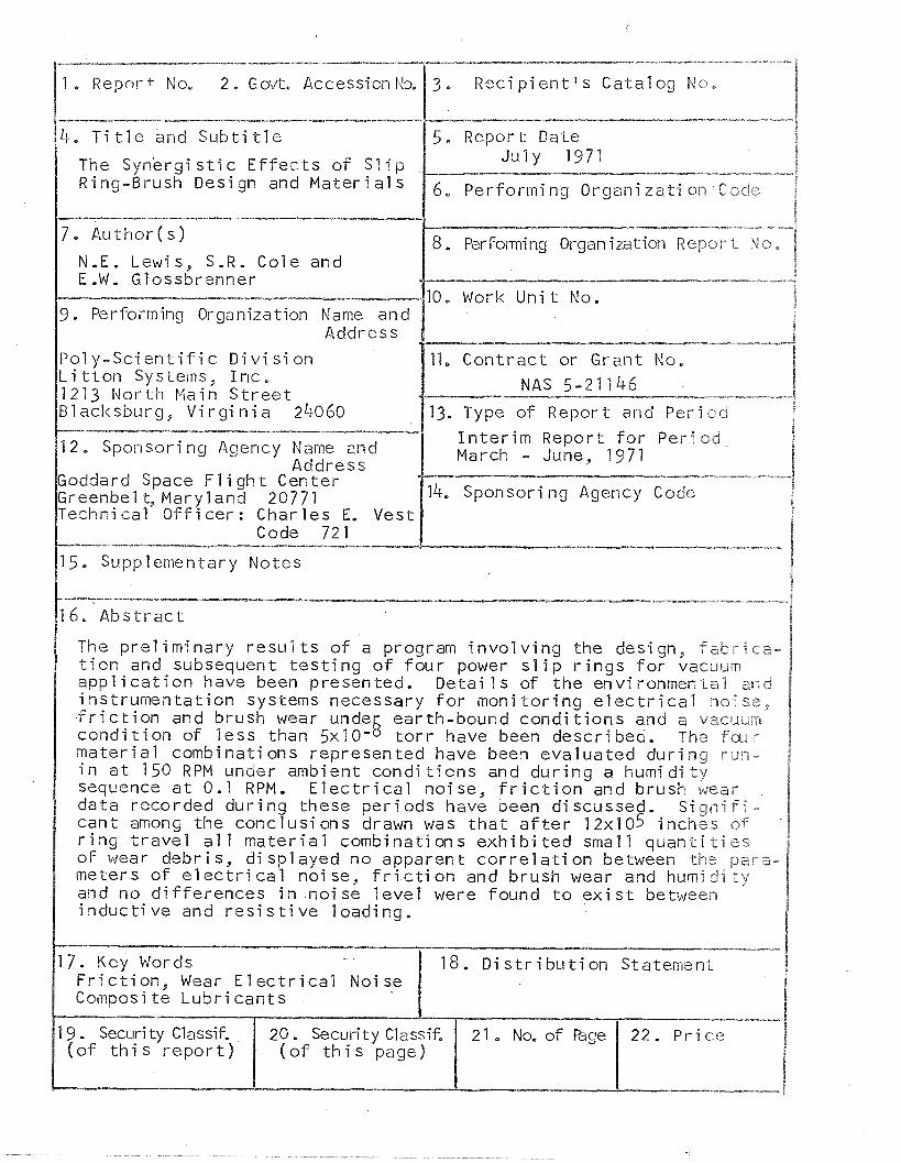
--.---.--------.- 1 . Repor f- No, 2, Govt, Accession Na 3, R e c i p i e n t ' s Ca ta log No,
4.- T i t l e and S u b t i t l e 15. Report Date I The Synergi s t i c E f f e c t s o f S l i p
J u l y 1971 -------~-"------ -*---*-
Ring-Brush Design and M a t e r i a l s r m i ng Organi z a t i on Cock
N - E . Lewis, S.R. Co le and E ,W. Glossbrenner
9. Performing Organization Name and Address
P o l y - S c i e n t i f i c D i v i s i o n L i t t o n Systems, I n c . 1213 N o r t h Main S t r e e t Blacksburg, V i r g i n i a 24060
12, Sponsoring Agency Name and Address
Goddard Space F l i g h t Center Greenbel t, Maryland 20771 Techni ca l O f f i ce r : Char les E. Vest
Code 721
15. Supplementary Notes
8, P~rfonning Organization Repor- t No,
10, Work U n i t No.
-
11, C o n t r a c t or Grant No,
NAS 5-2 1 1 46
13. Type o f Report and Pe r i od
I n t e r i m Report f o r Pericsd March - June, 1971
-- -- - ----. --. -----*-**- 14. Sponsor i ng Agency Code
The p r e l i m i n a r y r e s u l t s o f a program i n v o l v i n g the design, f a b r i c a - t i o n and subsequent t e s t i n g o f f o u r power s l i p r i n g s f o r vacuum a p p l i c a t i o n have been presented, Deta i I s o f t he environmental znd i ns t rumen ta t i on systems necessary f o r m o n i t o r i n g e l e c t r i c a l no ise, f r i c t i o n and brush wear undeb earth-bound c o n d i t i o n s and a v a c u ~ ~ r ; c o n d i t i o n of l e s s than 5x10- t o r r have been descr ibed. The f m r m a t e r i a l combinat ions represented have been eva lua ted d u r i n g r u n - i n a t I 5 0 RPM under ambient c o n d i t i o n s and d u r i n g a humid i t y sequence a t 0 - 1 RPM. E l e c t r i c a l noise, f r i c t i o n and brush wear data recorded d u r i n g these pe r i ods have been discussed. S i g n i f i - can t among the conc lus ions drawn was t h a t a f t e r 12x105 inches of r i n g t r a v e l a1 1 m a t e r i a l combinat ions e x h i b i t e d small q u a n t i t i e s of wear debr is , d i sp layed no apparent c o r r e l a t i o n between the par6;- meters of e l e c t r i c a l noise, f r i c t i o n and brush wear and humidiey and no d i f fe rences i n no i se l e v e l were found t o e x i s t between i n d u c t i v e and r e s i s t i v e load ing ,
---- ----. 7. Key Words 8. D i s t r i b u t i o n Statement F r i c t i o n , Wear E l e c t r i c a l Noise Composi t e L u b r i c a n t s
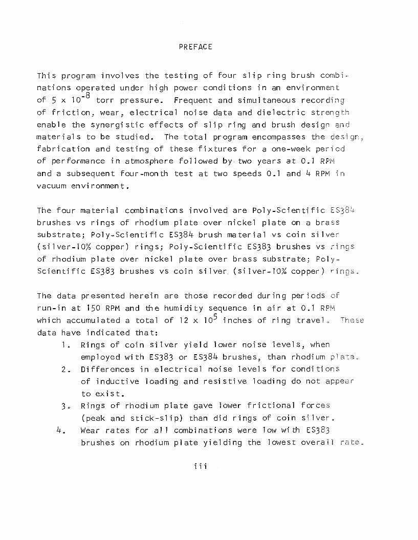
PREFACE
Th i s program i n v o l v e s the t e s t i n g o f f o u r s l i p r i n g brush combi-
n a t i o n s operated under h i g h power condi t i o n s i n an environment
of 5 x t o r r pressure. Frequent and simul taneous reco rd ing
o f f r i c t i o n , wear, e l e c t r i c a l no i se data and d i e l e c t r i c s t r e n g t h
enable the s y n e r g i s t i c e f f e c t s o f s l i p r i n g and brush design and
m a t e r i a l s t o be s tud ied. The t o t a l program encompasses the design,
f a b r i c a t i o n and t e s t i n g o f these f i x t u r e s f o r a one-week p e r i o d
of performance i n atmosphere f o l l o w e d by two years a t 0.1 RPM
and a subsequent four-month t e s t a t two speeds 0.1 and 4 RPM i n
vacuum env i ronmen t .
The f o u r m a t e r i a l combinat ions i n v o l v e d a re P o l y - S c i e n t i f i c E S 3 8 4 brushes vs r i n g s o f rhodium p l a t e over n i c k e l p l a t e on a brass
subs t ra te ; Po l y -Sc ien t i f i c ES384 brush m a t e r i a l vs c o i n s i l v e r
( s i l ve r -10% copper) r i n g s ; P o l y - S c i e n t i f i c ES383 brushes vs r i n g s
o f rhodium p l a t e over n i c k e l p l a t e over b rass subs t ra te ; Po ly -
S c i e n t i f i c ES383 brushes vs c o i n s i l v e r ( s i l ve r -10% copper) r i n g s ,
The data presented h e r e i n a re those recorded d u r i n g per iods o f
r u n - i n a t 150 RPM and the humid i t y sequence i n a i r a t 0.1 RPM 5 which accumulated a t o t a l o f 12 x 10 inches o f r i ng t r a v e l , These
data have i n d i c a t e d t h a t :
1 , Rings o f c o i n s i l v e r y i e l d lower n o i s e l eve l s , when,
employed w i t h ES383 or ES384 brushes, than rhodium p l a t e ,
2, D i f f e r e n c e s i n e l e c t r i c a l no i se l e v e l s f o r c o n d i t i o n s
o f i n d u c t i v e l oad ing and r e s i s t i v e l oad ing do n o t appear
t o e x i s t ,
3, Rings o f rhodium p l a t e gave lower f r i c t i o n a l f o r c e s
(peak and s t i c k - s l i p ) than d i d r i n g s o f c o i n s i l v e r ,
4. Wear r a t e s f o r a1 1 combinat ions were low w i th ES383
brushes on rhodium p l a t e y i e l d i n g the lowest o v e r a l l r a t e ,
iii

5. Cor re la t ions between the parameters of e l e c t r i c a l noi se,
f r i c t i o n and brush wear and humidity do not appear,
I t i s recommended t h a t the two year vacuum t e s t continue and d a t a
be col lec ted a t a frequency of twice per week.

TABLE OF CONTENTS
Sec t ion T i t l e laaae
PREFACE . . . . . . . . . . . . . . . . . . . . - i i i
INTRODUCTION . . . . . . . , . . . . . . . . . . 1
EXPERIMENTAL . . . . . . . . . . . . . . . . . . 3 A. System Hardware . . . . . . . . . . . . . . . '3
1 . Test F i x t u r e s . . . . . . . . . . . . . . 3 2. Power System . . . . . . . . . . . . . . 4 3 . F r i c t i o n . E l e c t r i c a l Noise and Wear
Systems . . . . . . . . . . . . . . . . . 4 4 . Environmental Chambers . . . . . . . . . . 6
B . C a l i b r a t i o n o f Systems . . . . . . . . . . . 6 C . Brush M a t e r i a l P r o p e r t i e s and Estab l i s h -
ment o f S p e c i f i c a t i o n s . . . . . . . . . 7
DATA . . . . . . . . . . . . . . . . . . . . . . '80 . . . . . . . . . . . . . . . A. R u n 4 n D a t a . -10
B. Humid i ty Data . . . . . . . . . . . . . . . . 1 1
I V D I S C U S S I O N OF RESULTS . . . . . . . . . . . . . . 1 2
V NEW TECHNOLOGY . . . . . . . . . . . . . . . 18
. . . . . . . . V I PROGRAM FOR NEXT REPORTING P E R I O D 19
V I I CONCLUSIONS. . . . . . . . . . . . . . . . . . - 2 0 V I I I RECOMMENDATIONS . . . . . . . . . . . . . . . - 2 1
A P P E N D I X E S
A . Engineer i ng S p e c i f i c a t i o n 383 . . . . . . . . . . . 66 . . . . . . . . . . . . B Eng ineer ing S p e c i f i c a t i o n 384 71

LIST OF FIGURES
T i t l e Page -- Figure
1 Capsule Assembly Drawing Showing Trans- ducer Mounting , , . . . . . . . , , . . 22
Test F i x t u res Mounted i n Vacuum Chamber. , , 23
Block Diagram o f Power and Transducer Systems . , . . . , . . , . , , , , . , 24
Vacuum Chamber and Test Console w i th E igh t Channel Recorder . , . . , . , . , 25
Shear Strength Test Apparatus , . . . . 26 Shear Strength Test Apparatus Close-Up . . , 27
R e s i s t i v i t y Sample Test Close-Up . , . . , . 28 Normal Section of ES383 , . . . . . . , . 29
Long i tud ina l Section of ~ S 3 8 3 . . . .. . .. '30
Normal Sect ion o f ES384 . . . , . . . . . , 3 1
Long i tud ina l Section of ES384 . . . . , . , 32 Noise (P-P) During Run-In A t 150 RPM
(ES383 - Rhodium P la te ) . . , . . , . , 33
Noise (P-P) Dur ing Run-In A t 150 RPM (ES383 - Coin S i l v e r ) . . . . * . e - 3 4
Noise (P-P) During Run-In A t 150 RPM (ES384 - Rhodium P la te ) . , , . . , , . , 35
Noi se (P-P) During Run-In A t 150 RPM (ES384 - Coin S i l v e r ) . , , , . , . . . 3 6
Peak F r i c t i o n During Run-In A t 150 RPM (ES383 - Rhodium P la te ) . . . . . , 37
Peak F r i c t i o n During Run-In A t 150 RPM (ES383 - Coin S i 1 ver ) . . . . . . . . 38
Peak F r i c t i o n During Run-In A t 150 RPM (ES384 - Rhodium P la te ) . . , . , . . . 39
Peak F r i c t i o n During Run-In A t 150 RPM (ES384 - Coin S i l v e r ) . . . . . . . . * k0

LIST OF FIGURES - CONTINUED
F igure
19
T i t l e -- S t i c k - S l i p F r i c t i o n During Run-In A t
150 RPM (ES383 - Rhodium P la te ) . . . . 41 St ick-S l i p F r i c t i o n During Run-In A t
150RPM (ES383 - C o i n s i l v e r ) . . . . . 42 St i ck -S l i p F r i c t i o n During Run-In A t
150 RPM (ES384 - Rhodium P la te) , . . , 43
S t i c k - S l i p F r i c t i o n During Run-In A t 150RPM (ES384 - C o i n s i l v e r ) . , . , 44
Total Brush D i spl acement Dur i ng Run- I n A t 150 RPM . . . . . . . . . . . . . 45
Noise (P-P) During Humidi t A t 0.1 RPM , 46 (ES383 - Rhodium P la te Y
Noise (P-P) During Humidity A t 0,l RPM . (ES383 Coin S i l v e r ) . . . . . . . . . 47
Noise (P-P) During Humidi t A t 0.1 RPM (ES384 - Rhodium P la te Y . . . . 48
Noise (P-P) During Humidi ty A t 0.1 RPM (ES384 . Coin S i l v e r ) . . . . . . . . . 49
Peak F r i c t i o n During Humidity A t 0.1 RPM (ES383 - Rhodium P la te ) . , , . . , . , 50
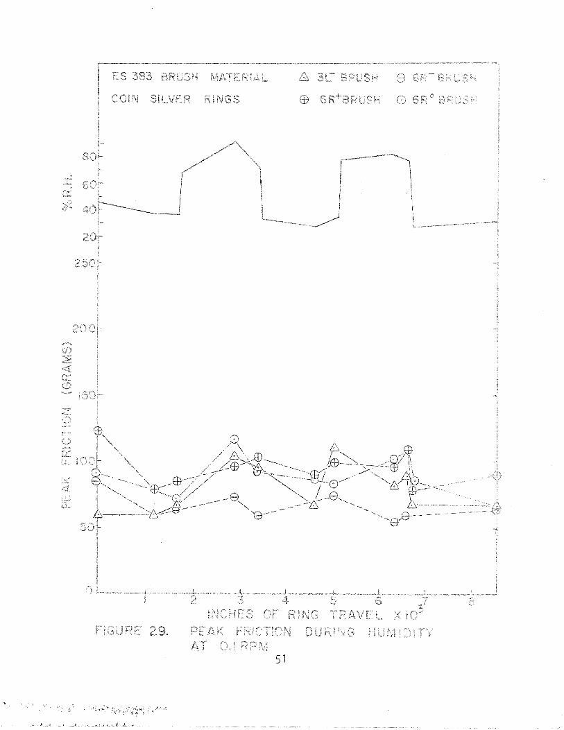
Peak F r i c t i o n During Humidity A t 0.1 RPM . (ES383 Coin S i l v e r ) . . . . . . . . . 51
Peak F r i c t i o n During Humidity A t 0.1 RPM (ES384 - Rhodium P la te ) . . . . 52
Peak F r i c t i o n During Humidity A t 0.1 RPM . ( ~ S 3 8 4 Coin S i l v e r ) . . . . . . . . . 53
S t i c k - S l i p F r i c t i o n During Humidit A t 0.1 RPM (ES383 - Rhodium PlateY . . . . 54
S t i c k - S l i p F r i c t i o n Duri ng Humidity A t 0.1 RPM (ES383 - C o i n S i l v e r ) . . . 55
S t i c k - S l i p F r i c t i o n During Humidi t A t 0.1 RPM (ES384 - Rhodium Plate! . , . 56
St i ck -S l i p F r i c t i o n During Humidity A t - . 0.1 RPM ( ~ S 3 8 4 Coin S i l v e r ) 57

F i g u r e
3 6
LIST OF FIGURES - CONTINUED
T i t l e Page -- Brush D i ~ p l a c e m e n t Duri ng Humid i t y A t
0.1 RPM (ES383 - Rhodium P l a t e ) . . 58
Brush Displacement Dur ing Humid i ty A t 0.1 RPM(ES383 - C o i n s i l v e r ) . , , , , 59
Brush Displacement Dur ing Humid i ty A t 0.1 RPM (ES384 - Rhodium P l a t e ) . , . , 60
Brush Displacement Dur ing Humidi t y A t 0.1 RPM (ES384 - Coin S i l v e r ) . , , . , 61

LIST OF TABLES
Table
I
I I
T i t l e Page -- Simultaneous Data C o l l e c t i o n Sequence , , .62
Datd From 12% MoS2, 3% Graphi te, 85% Ag Composi t e s , , . , , . , , , , , , . , -63
Data From 15% NbSe2, 3% Graphi te, 82% Ag Composites .. . . . . . . . , . . -64
Sumnary Of Phys ica l Data For Composite Brush M a t e r i a l . . . , . . . . . . . -65

THE S Y N E R G I S T I C EFFECTS OF SLIP
R ING-BRUSH D E S I G N AND MATERIALS
by N. E, Lewis
S. R . Cole
and
E. W. Glossbrenner
Pol y -Sc ien t i f i c D i v i s i o n
L i t t o n Systems, I n c ,
I. INTRODUCTION
The increas ing l i f e o f space miss ions i s imposing more s t r i n g e n t
requirements on s l i d i ng contac t devices. These miss ions may
r e q u i r e s l i d i n g contac t devices t o operate cont inuously f o r pe r i ods
i n excess o f 10 years. The design and choice o f m a t e r i a l s necessary
t o f a b r i c a t e a s l i d i n g contac t device capable o f s a t i s f y i n g l o n g l i f e t i m e requirements must be supported by t e s t data. To p rov ide
the data concurrent w i th t h e need i t i s necessary t o perform
experiments on an accelerated bas is .
A Program t o study the s y n e r g i s t i c e f f e c t s o f s l i p r i n g design
and m a t e r i a l s i s c u r r e n t ? y underway t o p rov i de data fo r synchranous
o r b i t power s l i p r i n g app l i ca t i ons . Th is program invo lves t h e
design, f a b r i c a t i o n and t e s t i n g of four power s l i p r i n g s repre-
sent ing fou r r i n g and brush m a t e r i a l combinations under a sequence
of earth-bound cond i t i ons and a vacuum environment o f l e s s than
5x1 os8 t o r r . The simulated I i f e experiments are being conducted
on an accelerated bas i s by running the f i x t u r e s a t a speed of : ( a )
150 RPM dur ing a 10 hour r u n - i n per iod, (b) 0 - 1 RPM dur ing the 5- day earth-bound cond i t i on , and ( c ) 0 - 1 RPM dur ing the two year vacuum cond i t i on , A f t e r complet ion of the two year t e s t and a
post t e s t ana lys i s the p a r t s w i l l be re fu rb i shed and a four monrh vacuum t e s t a l t e r n a t i n g between r o t o r speeds o f 0.1 and 4 RPM will
1

be conducted. A l l t e s t s are be ing conducted w i t h a brush
cu r ren t dens i ty o f 100 amps/sq. i n .
The f a r r i n g and brush m a t e r i a l combinations under eva lua t ion
are as f o l lows :
( A ) P o l y - S c i e n t i f i c ES383 brushes vs r i n g s o f rhodium
p l a t e over n i c k e l p l a t e on a brass subs t ra te (Combination A )
(B) P o l y - S c i e n t i f i c ES383 brush vs c o i n s i l v e r ( s i l v e r
-10% copper) r i n g s (Combinati on B)
(C) P o l y - S c i e n t i f i c ES384 brushes vs r i n g s o f rhodium
p l a t e over n i c k e l p l a t e on a brass subs t ra te (Combination 6 )
(D) P o l y - S c i e n t i f i c ES384 brushes vs co in s i l v e r r i n g s
(Combination D),
P o l y - S c i e n t i f i c ES383 i s an engineer ing s p e c i f i c a t i o n f o r brushes
composed o f 85% s i I ver -12% molybdenum di s u l f i de-3% graphi te,
ES384 s imi l a r l y def ines t h e 82% s i lver-15% niobium diselen-r" de-3% graphi te , mrnposite. These s p e c i f i c a t i o n s have been inc luded in
the Appendix. E l e c t r i c a l noise, f r i c t i o n and wear data a re be ing
c o l l ected dur ing the run- in , earth-bcund and vacuum condi t i o n s t o
evaluate the performance o f the four mater ia 1 combinations,
A t t h i s p o i n t the 10-hour r u n - i n per iod, the 5-day earth-bound
t e s t and the i n i t i a t i o n o f the two year vacuum t e s t have been
completed. Data are being presented t h a t were generated dur ing
the r u n - i n and 5-day e a r t h - b a n d condi ti ons.

II. Experimental
A. System Hardware
1 . Test F i x t u r e s
The f i x t u r e s be ing used i n t h i s s tudy a r e 6 - c i r c u i t assemblies
which u t i 1 i z e two c u r r e n t - c a r r y i n g brushes per r i n g (F igu re 1 ,%
The s i x t h r i n g o f each f i x t u r e c a r r i e s a t h i r d brush w i t h mechanj-
c a l l oad ing on ly . Current i s d i r e c t e d i n one brush and ou t the
o ther , thus g i v i n g a p o s i t i v e and nega t i ve brush on each r i n g ,
Each brush i s l o c a t e d i n a separate t r a c k t o min imize t he e f f e c t
o f wear deb r i s f rom the o the r brushes on t h e same r i n g , Wear
d e b r i s management has a l s o been f a c i l i t a t e d by t he use o f 50 m i l
h i g h b a r r i e r s between r i n g s and open s e c t i o n s i n t h e bot tom o f
t h e frame.
Measurement o f brush wear was accomplished by l o c a t i n g t he core
o f a l i n e a r v a r i a b l e d i f f e r e n t i a l t ransformer LVDT ( I t e m 20)9< on
t h e brush s h a f t . Wear stops ( I t em 25 ) l o c a t e d on t h e end o f t h e
brush s h a f t have been ad jus ted t o c o n s t r a i n brush movement after
30 m i l s o f wear has occurred. An e l e c t r i c a l con tac t ( I tem 24) gauged 30 m i l s from t h e wear stop, has been l o c a t e d on t h e brush
assembly as means of d i s t i n g u i s h i n g 30 m i l s o f wear f rom a b r u s h -
s p r i n g ma1 f u n c t i o n .
The e n t i r e brush assembly i s a t t ached t o t h e frame by b e r y l l i u m
copper sp r i ngs ( I t e m 8 ) which form t h e ends o f a para l le logram,
These sp r i ngs have been designed t o permi t l i n e a r mot ion i n the
d i r e c t i o n o f t he f r i c t i o n a l f o r c e and a c t as r i g i d members to i
fo rces i n o t h e r d i r e c t i cns. ~ e ~ a t o r ~ ~ sp r i ngs were employed t o
y i e l d a cons tan t b rush f o r c e (170 grams nomina l ) as t h e b rush
wears. The brushes have been mounted w i t h a 15' t r a i l i n g ang le
Var ious fea tu res of t h e f i x t u r e a r e i d e n t i f i e d by i t e m number
o f F i g u r e 1.
TM - Hunter Spr ing Company
3

w i t h respect t o the r i n g normal t o minimize " s t i c k - s l i p " . The
t a n p n t i a l f r i c t i o n f o r c e exer ted on the brush by the r i n g is
sensed as a brush b lock displacement us ing a p rox im i t y sensor
( I t e m 28).
Transducers f o r measuring wear and f r i c t i o n are loca ted on the
pos i t i ve , negat ive and neu t ra l brushes on the s i x t h r i n g and t he
negat ive brush o f the t h i r d r i n g .
2. Power System
The power system, a block diagram o f which has been presented i n
Figure 2, was designed t o permi t three o f the s i x r i n g s on each
f i x t u r e t o be placed under an i n d u c t i v e and r e s i s t i v e (50 mh,
12 ohm) load and t h e remaining th ree on each f i x t u r e under a r e s i s - t i v e (12 ohm) load only . Two Lambda model LB-705-FM power s u p p l i e s
were used t o supply the c u r r e n t t o the r e s i s t i v e and i n d u c t i v e
r i n g s of a l l f i x t u r e s , A1 1 the r i n g s and brushes on the four
f i x t u r e s hav ing a common type o f load were connected i n a ser jes
c i r c u i t. I n each c i r c u i t twelve one-ohm r e s i s t o r s were e l e c t r i c a l l y
l oca ted between the twelve r i n g s t o l i m i t the c u r r e n t t o 8.33 amperes a t 100 v o l t s dc (min) . A s i l i c o n - c o n t r o l l e d r e c t i f i e r by-
pass network has been prov ided f o r each r i n g and brush p a i r i n t h e
event an open c i r c u i t c o n d i t i o n l a s t i n g more than 50 m i I i seconds
devel ops.
Switch panel s have a l s o been incorpora ted i n each c i r c u i t which
w i l l permi t the c u r r e n t t o be re rou ted i n the even a shor t (or
mu1 ti p l e shor ts ) occurs between any r i n g combi na t i on . U t i l i z i n g
the se r ies c i r c u i t r y w i t h the necessary bypass networks ra ther
than a p a r a l l e l arrangement al lowed the c u r r e n t requirements t o
be dropped from 100 amps t o 8.33 amps per power supply,
3. F r i c t i o n , E l e c t r i c a l Noise and Wear System
A block diagram represent ing t y p i c a l f r i c t i o n , no ise and wear
c i r c u i t s has a l s o been presented i n F igu re 2. The wear and f r i c -
4
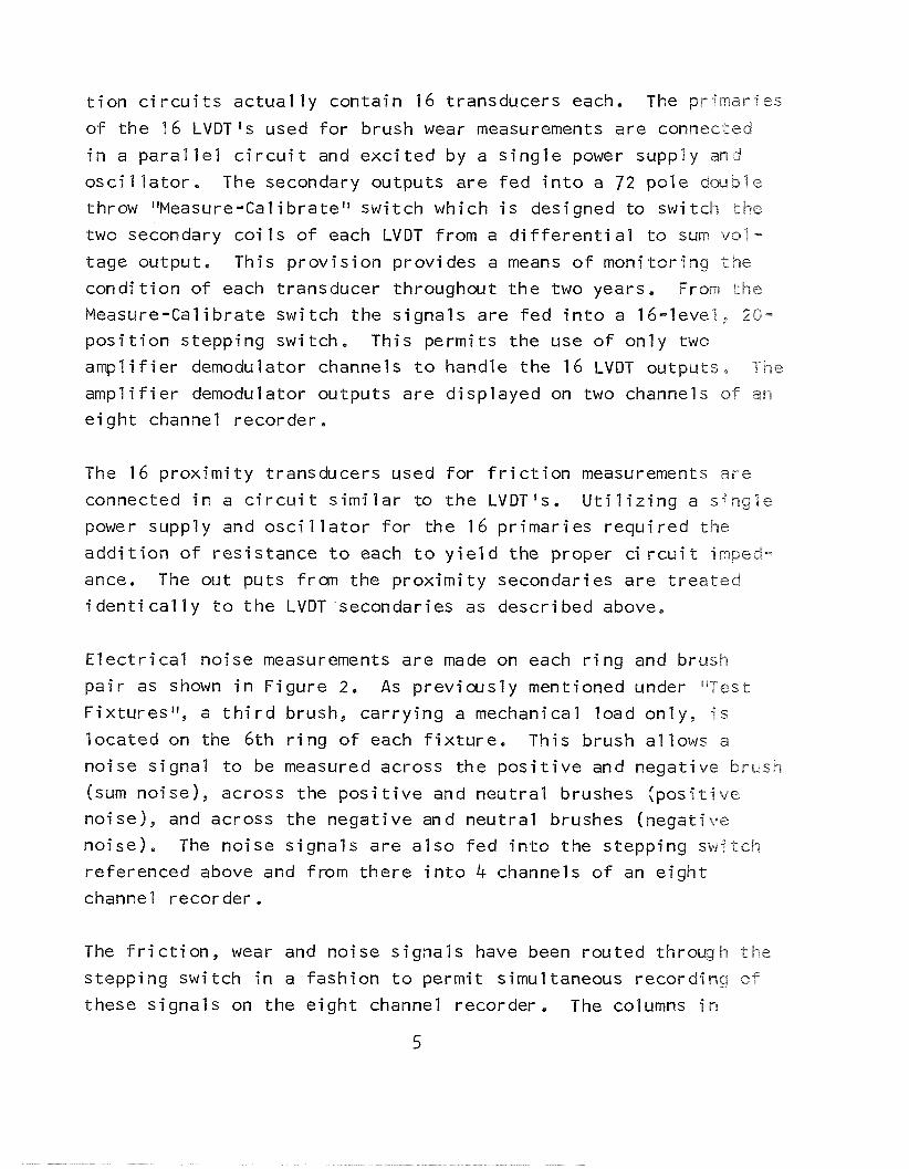
t i o n c i r c u i t s ac tua l l y con ta in 16 transducers each. The pr imar ies
o f t h e 16 LVDT1s used f o r brush wear measurements a re connected
i n a p a r a l l e l c i r c u i t and e x c i t e d by a s i n g l e power supply and
o s c i l l a t o r . The secondary outputs a re f e d i n t o a 7 2 p o l e d m b l e
throw "Measure-Cal i b r a t e i l sw i tch which i s designed t o swi tclh t h e
two secondary c o i l s o f each LVDT from a d i f f e r e n t i a l t o sum val-
tage output. This p r o v i s i o n prov ides a means o f mon i to r i ng the c o n d i t i o n o f each transducer throughout t h e two years. From the
Measure-Calibrate swi tch the s i g n a l s a re f e d i n t o a 16- level , 20-
p o s i t i o n s tepping switch. This permi ts the use o f on l y two
a m p l i f i e r demodulator channels t o handle the 16 LVDT outputs, The
a m p l i f i e r demodulator outputs a re d isp layed on two channels o f an
e i g h t channel recorder .
The 16 p r o x i m i t y t ransducers used f o r f r i c t i o n measurements a re
connected i n a c i r c u i t s i m i l a r t o t h e LVDTfs. U t i l i z i n g a single
power supply and osc i 1 l a t o r f o r t he 16 p r imar ies r e q u i r e d the
a d d i t i o n o f res i s tance t o each t o y i e l d the proper ci r c u i t imped-
ance. The out puts from the p r o x i m i t y secondaries a re t r e a t e d
i d e n t i c a l l y t o t h e LVDT secondaries as descr ibed above.
E l e c t r i c a l no ise measurements a r e made on each r i n g and brush
p a i r as shown i n F igure 2. As p rev ious l y mentioned under [ 'Test
F ix tu res I f , a t h i r d brush, c a r r y i n g a mechanical load only , i s
l oca ted on the 6 th r i n g o f each f i x t u r e . This brush a1 lows a
no ise s igna l t o be measured across the p o s i t i v e and negat ive brush
(sum no ise) , across the p o s i t i v e and n e u t r a l brushes ( p o s i t i v e
no ise) , and across the negat ive and neu t ra l brushes (negat ive
no ise ) . The no ise s igna ls a re a l s o f e d i n t o the s tepping s w i t c h
re ferenced above and from t h e r e i n t o 4 channels o f an e i g h t
channel recorder .
The f r i c t i o n , wear and no ise s igna ls have been rou ted through t h e
s tepping swi tch i n a fash ion t o permit simultaneous record ing of
these s igna ls on the e i g h t channel recorder , The columns ii-I
5

Table I show the s igna ls t ha t a re recorded simultaneously on the
e i g h t channe 1 recorder . 4. Envi ronmental Chambers
The 10-hour r un - i n and 5-day humid i ty t e s t s were performed i n a
Blue M model VP-100A humid i ty chamber. The 10-hour r un - i n period
f o r each f i x t u r e was performed w i t h b e l l j a r removed and there-.
f o r e under ambient cond i t ions . The 5-day humidity t e s t was p e r -
formed by ad jus t i ng wet and dry bu lb con t r o l s t o y i e l d the lowest humidi t y cond i t i on possible (30-40%) f o r 24 hours and then
ad jus t i ng these con t ro l s t o y i e l d 70080% fo r 24 hours. T h i s 48- hour cyc l e was repeated once w i t h the f i f t h 24-hour pe r iod a t
30-40%.
A Perkin-Elmer U l t ek vacuum system, which has been shown i n
F igure 3 along w i t h t e s t console and recorder, equipped w i t h con-
vent iona l i o n pumps and d i f f e r e n t i a l i o n pumps, i s being used for
t he vacuum environment. The pumping speeds fo r n i t rogen, argon
and hel ium are 700 L/S, 45 L/S and 100 L/S respec t i ve l y . Roughing
was achieved by us ing two so rp t i on pumps. Four one foot-pound
r o t a r y motion feedthroughs dr iven by gear -reduced synchronous
motors are being employed t o r o t a t e the s l i p r i ngs a t 0.1 RPM,
The vacuum bearings i n these u n i t s were l u b r i c a t e d us ing the
Microseal l u b r i c a t i o n process. A l l e l e c t r i c a l connections were made through n ine Deutsch 37 p in , 7.5 amp feedthroughs,
Clean, dry and empty t h i s system was capable o f less than 2 ~ 1 0 ~ ~
t o r r . The base pressure obta ined t o date w i t h f ixtures-transducers -8 and associated lead w i r e w i th power on was 3x10 t o r r ,
B. Ca l i b ra t i on o f Systems
The c a l i b r a t i o n sequence cons is ted o f performing a p re l im ina ry
c a l i b r a t i o n of a1 1 wear (LVDT) and f r i c t i o n ( p rox im i t y ) t r ans -
ducers be fore the 10-hour r u n - i n per iod. Since the r i n g t r a v e l

dur ing the 10-hour r un - i n pe r iod a t 150 RPM i s greater than t h e
t o t a l t r a v e l w i l l be dur ing t h e two year vacuum pe r i od a t 0,1
RPM, i t was a n t i c i p a t e d t h a t s u f f i c i e n t brush displacement and
f r i c t i o n changes woul d occur which w a r 1 d necessi t a t e r e s e t t i n g
t he zero po i n t s and r e c a l i b r a t i n g the transducers. Thus the
transducers on each p a r t were g iven a f i n a l c a l i b r a t i o n p r i o r t o
i n s t a l l a t i o n i n the vacuum chamber.
The LVDT l s were c a l i b r a t e d by adapt ing a micrometer t o the
transformer support (F igure 1, I tem 18), coup l ing t he micrometer
b a r r e l t o t he brush s h a f t w i t h a un ive rsa l j o i n t and shimming
the case and transformer ( I t em 20) 0.040 w i t h respect t o the
brush shaf t . This arrangement prov ided an accurate means o f
moving the brush from the r i n g contact p o s i t i o n r a d i a l l y outward
over a displacement reg ion which dup l ica tes a brush displacement
r a d i a l l y inward w i t h shims removed. The p rox im i t y transducers
were c a l i b r a t e d by l i f t i n g t h e brushes from the r i n g and hanging
weights from t he brush holder ( I t em 30). Applying t h e weight
t o t h i s p o s i t i o n prov ided a means o f dup l i ca t i ng the p o i n t of a p p l i c a t i o n o f the f r i c t i o n a l f o r ce occur r ing between the r i n g
and brush.
C. Brush Mater ia l Proper t ies and Establishment o f Spec i f i ca t i ons
P o l y - S c i e n t i f i c has found t ha t the p roper t i es o f metal -sol i d
l ub r i can t s composites vary g r e a t l y from l o t t o l o t and vendor t o
vendor, A t l eas t p a r t o f t he v a r i a t i o n i n ma te r i a l can be related
t o the f a c t t ha t adequate spec i f i ca t i ons do not e x i s t f o r insfrum-
ment grade brushes. There i s a need fo r spec i f i ca t i ons t h a t
adequately de f ine the p roper t i es o f metal -sol i d l ub r i can t s corn-
pos i tes t ha t a re t o be used i n c r i t i c a l , h i gh r e l i a b i l i t y a p p l i -
cat ions. Present ly, ma te r ia l s a re o f t e n def ined by vendor codes
which r e l a t e t o p rop r i e t o r y products. I n many cases even the
major cons t i t uen ts o f the composites are n o t p u b l i c knowledge,
Spec i f i ca t i ons should de f ine a l l c r i t i c a l phys ica l and chemical

proper t i e s and s t a t e how the p roper t i es can be measured on com-
pos i tes tha t may be q u i t e smal l i n s i z e (egg. . 0 2 0 1 1 X . 0 6 0 1 ~ X ~ 1 0 0 ~ ~ ~ ~
There a r e pub l i shed s p e c i f i c a t i o n s (e.g, A N S I ~64.1-1970) which cover composite brushes i n general, bu t p a r t s o f t h e s p e c i f i c a -
t i o n s cannot be appl ied, or a re not app l i cab le , t o small brushes
t h a t a re formed t o s ize .
Extensive t e s t s were made i n order t o de f i ne the p r o p e r t i e s of
the brushes procured f o r t h i s s p e c i f i c con t rac t and t o o b t a i n
data t h a t cou ld be used as a bas is f o r engineer ing s p e c i f i c a -
t i o n s , Hopeful ly, t r i b o l o g i c a l data can be r e ? a t e d t o the
phys ica l and chemical p r o p e r t i e s o f t h e brush m a t e r i a l .
Composite s t r e n g t h can be expected t o a f f e c t wear character as
we1 I as determine s t r u c t u r a l design I i m i t a t i o n s . The standard
method f o r measuring composite s t r e n g t h i s t o use th ree -po in t
loading and measure t h e t ransverse s t r e n g t h ( re fe rence paragraph
4.6, A N S I C64.1-1970). This method i s n o t p r a c t i c a l f o r small instrument brushes t h a t a re molded t o s ize . The s t r e n g t h o f this type brush can be readi l y measured by d i r e c t shear. Figures 4 and 5 show the apparatus used by P o l y - S c i e n t i f i c f o r measuring
the shear s t r e n g t h o f t h e composites. I t was cons t ruc ted f r o m a
Model 6-092-01 Un i tek M ic ropu l l St rength Tester and a j ewe le r l s
v ice . Since the shear s t r e n g t h o f a molded brush depends on the
p lane o f shear, i t i s necessary t o de f i ne the plane o f shear
r e l a t i v e t o the d i r e c t i o n o f p ress ing (See F igu re 1 o f ES383 or ~S384) . The s p e c i f i c res i s tance o f small composite samples was
measured w i t h the brush assembly shown i n F igure 6. Current was
passed through t h e composites v i a the end brush. Potentiometer
leads were connected t o the brushes adjacent t o the cu r ren t
c a r r y i n g ones. The s i x center p a i r s o f brushes were i n s u l a t e d
from each other and served on ly t o h o l d the sample. The cur ren t
was he1 d t o the minimum necessary t o ob ta in an accurate vo l tage
reading i n order t o minimize r e s i s t i v e heat ing. S p e c i f i c r e s i s -
tance was c a l c u l a t e d i n t h e standard manner (egg, paragraph 4 ,4 ,3

A N S I ~64.1-1970) .
Apparent dens i t y i s w i d e l y re fe renced as an i n d i c a t i o n of corn-
p o s i t e soundness. I t i s easy t o measure and i s one i n d i c a t i o n
o f t h e degree o f u n i f o r m i t y f rom l o t t o l o t . A composite w i t h
a very low dens i t y ( ~ 7 0 % t h e o r e t i c a l ) i s l i k e l y t o f r a c t u r e or crumble. The apparent d e n s i t y was s p e c i f i e d as grams per cubic cen t imete r and as a percent o f t h e o r e t i c a l dens i t y , The thes re -
t i c a l d e n s i t y was c a l c u l a t e d on the b a s i s o f pub l i shed d e n s i t i e s 3 f o r pure c o n s t i t u e n t s (e.g., Ag-10.5 g/cm3; graphi te-2.25 g/cm 1.
The a c t u a l shear s t reng th , dens i t y , and r e s i s t i v i t y data used
f o r t h e estab l ishment o f ES383 and ES384 a r e l i s t e d i n Tables
11, 111, and I V ,
Three or thogonal s e c t i o n s were m e t a l l o g r a p h i c a l l y examined f r o m
a t l e a s t two samples o f each l o t o f m a t e r i a l , T y p i c a l photomicro-
graphs a r e shown i n F igures 7, 8, 9 and 10. The m e t a l l o g r a p h i c
sec t i ons i n d i c a t e t h e composite s t r u c t u r e , degree o f p a r t i c l e
bonding and number and types o f f o r e i g n i n c l u s i o n s ,
Semiquan t i t a t i ve chemical analyses were performed by use o f an emiss ion spectograph. The c o n c e n t r a t i o n o f s i l v e r was v e r i f i e d
by use o f a tomic abso rp t i on spectrophotometry.
S p e c i f i c a t i o n s ES383 and ES384 shou ld a1 low one to o b t a i n brush
m a t e r i a l s ve ry s i m i l a r t o t h e ones t h a t were used f o r t h i s
c o n t r a c t . They a r e cons idered p r e l i m i n a r y o n l y because of t h e
smal l number o f l o t s used t o e s t a b l i s h t h e requirements f o r
s t r e n g t h and r e s i s t i v i t y . These s p e c i f i c a t i o n s were w r i t t e n
w i t h t h e assumption t h a t t h e m a t e r i a l s were t o be used f o r h igh -
r e l i a b i l i t y , ins t rument-grade s l i p r i n g s .
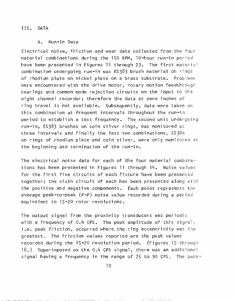
111. DATA
A. Run-In Data
E l e c t r i c a l noise, f r i c t i o n and wear data c o l l e c t e d from the four
ma te r ia l combinations dur ing the 150 RPM, 10-hour r un - i n pe r iod
have been presented i n Figures 11 through 23. The f i r s t ma te r ia l
combination undergoing r u n - i n was ES383 brush mate r ia l on r i ngs
o f rhodium p l a t e on n i c k e l p l a t e on a brass substrate. Problems
were encountered w i th the d r i v e motor, r o t a r y mot ion feedthrough
bear ings and common mode r e j e c t i o n c i r c u i t s on the i npu t t o the
e i gh t channel recorder; t he re fo re the data a t zero inches of
r i n g t r ave l i s not ava i l ab le . Subsequently, data were taken on
t h i s canbinat ion a t f requent i n t e r v a l s throughout the r un - i n
pe r i od t o es tab l i sh a t e s t frequency. The second u n i t undergoing
run- in, ES383 brushes on co i n s i l v e r r ings , was monitored a t
t h ree i n t e r v a l s and f i n a l l y the l a s t two combinations, ES384
on r i n g s o f rhodium p l a t e and co i n s i l v e r , were on ly monitored a t
t he beginning and te rminat ion o f the run- in .
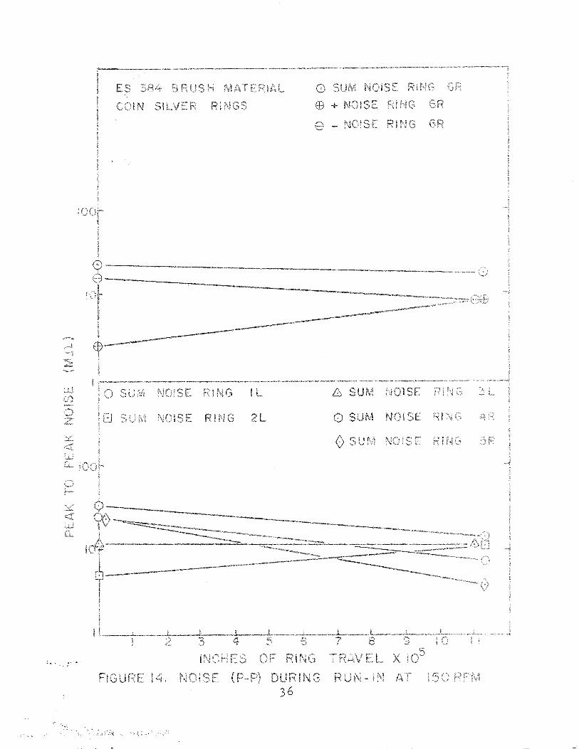
The e l e c t r i c a l no ise data f o r each o f the four ma te r ia l combina-
t i o n s has been presented i n Figures 1 1 through 14. Noise va l ues
f o r the f i r s t f i v e c i r c u i t s o f each f i x t u r e have been presented
together; t he s i x t h c i r c u i t o f each has been presented along w i t h
the p o s i t i v e and negat ive components. Each p o i n t represents t h e
average peak-to-peak (P-P) noise va lue recorded dur ing a pe r i od
equiva lent t o 15-20 r o t o r revo lu t i ons .
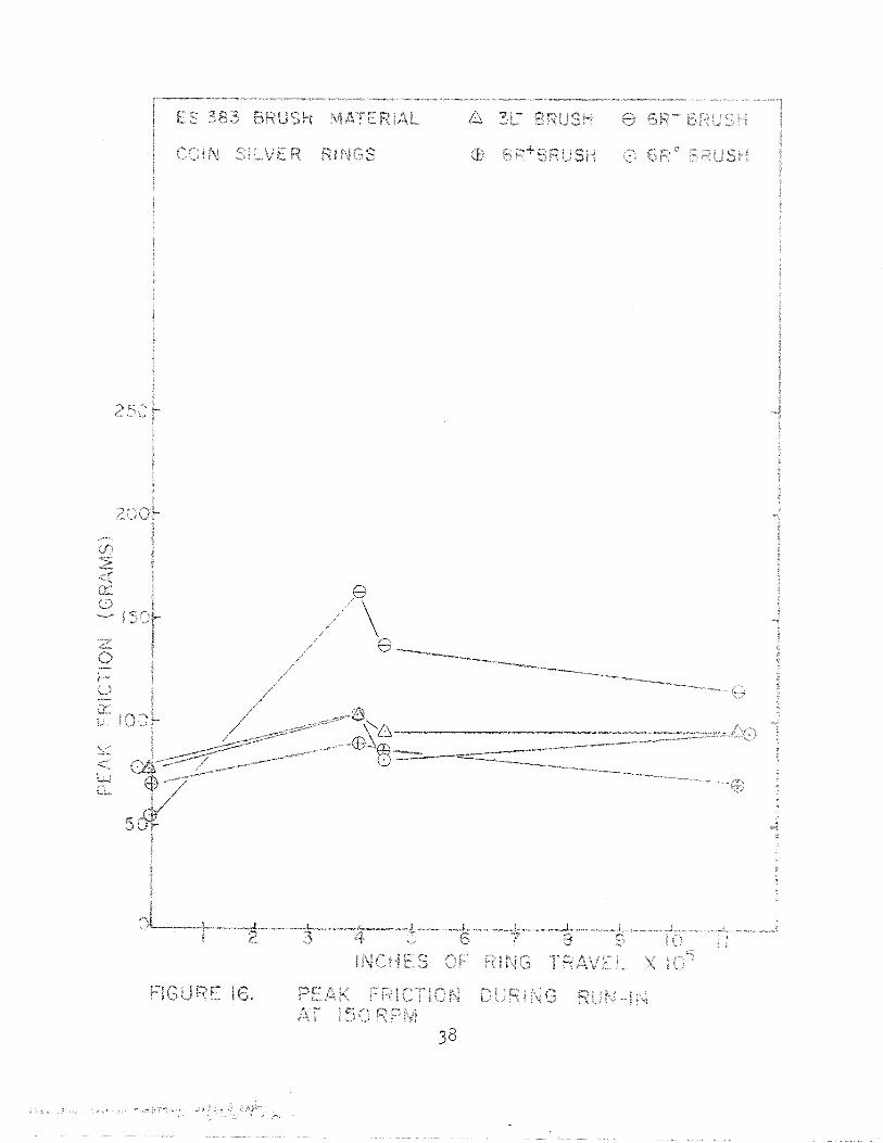
The output s igna l from the p rox im i t y transducers was pe r i od i c
w i t h a frequency o f 0.4 CPS. The peak ampl i tude o f t h i s s igna l ,
i .e . peak f r i c t i o n , occurred where the r i n g e c c e n t r i c i t y was t h e
greates t , The f r i c t i o n values repor ted a re the peak values
recorded dur ing the 15-20 r e v o l u t i o n per iod. (Figures 15 through
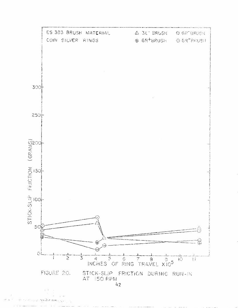
18.) Superimposed on t h e 0.4 CPS s igna l , there was an add i t i ona l
s igna l having a frequency i n the range o f 7 5 t o 90 CPS, The peak-
10
to-peak ampl i tude o f t h i s h igh frequency s igna l i s assumed to be
and has been repo r ted as s t i ck -s l i p f r i c t i o n (Figures 19 through
22).
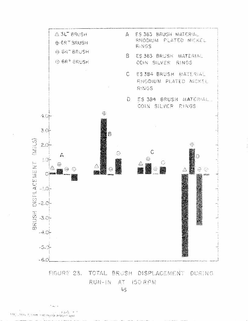
A re ference p o i n t on the wear t r a c e was selected, which i n a1 l
cases corresponded t o the maximum r i n g run-out, f o r mon i to r ing
the brush displacement. The ne t brush displacerrent occu r r i ng
dur ing the r u n - i n p e r i o d was the re fo re determined by t h e s h i f t
i n each reference p o i n t (F igure 23). A r a d i a l l y inward brush
displacement (wear) has been presented as a p o s i t i v e number w h i l e
r a d i a l l y outward displacements have been shown as a negat ive
number.
B. Humidity Test Data
The e l e c t r i c a l no ise and f r i c t i o n data c o l l e c t e d dur ing t h e 5- day humid i ty t e s t p e r i o d have been presented i n the same fashion
as t h a t c o l l e c t e d dur ing the 10-hour, 150 RPM r u n - i n per iod , In the case o f e l e c t r i c a l noise, each p o i n t graphed represents t h e
maximum peak-to-peak (P-P) no ise recorded du r i ng one r e v o l u t i o n
(Figures 24 through 27). The peak f r i c t i o n and peak-to-peak ( P - P I
s t i c k - s l i p f r i c t i o n values occu r r i ng dur ing the one r e v o l u t i o n
p e r i o d have been presented i n Figures 28 through 35. Although
t h e r o t o r speed was changed from 150 t o 0.1 RPM, the frequency
of the s t i c k - s l i p s igna l was r e l a t i v e l y constant. Each e n t r y 09
the brush displacerrent i l l u s t r a t i o n s represents the t o t a l brush
displacement t h a t has occurred from t h e beginning o f t h e hurnfdi t y
t e s t (Figures 36 through 39),
I n general, data were c o l l e c t e d a t t h e beginning o f t h e f i r s t
cycle, e i t h e r 7 or 16 hours l a t e r and 24 hours l a t e r . While t h e
t r a n s i t i o n between humid i ty l e v e l s was being made data were also c o l 1 ected. S ign i f i cant changes were no t detected dur ing these
t r a n s i t i o n s and therefore, f o r c l a r i t y , have no t been graphed, On
subsequent cyc les data were c o l l e c t e d a t 7 o r 16 and 24 hours
a f t e r the t r a n s i ti on.
1 1

I V . D I S C U S S I O N OF RESULTS
I n reviewing the data f o r each o f the four mater ia l combinations
an attempt w i 1 1 be made t o compare on ly l e ve l s and ranges ra the r
than perform formal s t a t i s t i c a l analyses. A l l data o f a common
type have been presented us ing i d e n t i c a l scales f o r bo th the run-
i n and humid i ty t e s t per iods for ease o f comparison. The humid i ty
l e ve l s have been presented w i t h t he 5-day t e s t data t o f a c i l i t a t e
co r re l a t i ons .
Beginning w i th e l e c t r i c a l no ise data recorded dur ing run - in for
ES383 brushes on rhodium p la te , i t can be seen t h a t i n i t i a l l y
the noise ranged from 9-30 mg and f i n a l l y the values increased
t o 15-50 m s ( F i g u r e 1 1 ) . Upon en te r ing the low humid i ty cyc le
t h i s combination remained i n the 15-50 mg region w i t h some c i r -
cu i t s reaching 60 mg before the 5-day cyc l e was completed ( ~ i g u r e
24). Comparison o f the no ise f l u c t u a t i o n s f o r t h i s combi na t ion
w i t h the humidi ty changes ind ica tes t ha t a s i g n i f i c a n t co r re l a -
t i o n does not e x i s t . The noise l eve l recorded f o r the p o s i t i v e
brush i s s i g n i f i c a n t l y lower than the negat ive brush dur ing run-- i n and humid i ty tes ts . The noise values f o r t he i nduc t i ve c i r c u i t s
I L , 2L and 3L dur ing bo th per iods do not appear t o be d i f f e r e n t
from the r e s i s t i v e c i r c u i t s 4 ~ , 5 R and 6R.
The ES383 brush - co in s i l v e r r i n g combination s t a r t e d r un - i n
w i t h noise values o f 4-9 mg and terminated r un - i n w i t h values
ranging from 4-15 mg (Figure 12). This l e ve l was constant when
the humid i ty t e s t was i n i t i a t e d with the except ion o f the 5R ring (F igure 25). A f t e r 16.5 hours under the low humid i ty cond i t ion ,
the spread was 7-20 m g and remained so throughout the remainder
of the humid i ty t e s t . The on ly c o r r e l a t i o n between humid i ty
l e v e l and noise f o r t h i s combination appears t o be t h a t occur r ing
a t the negat ive brush on the s i x t h r i n g . This brush dropped t o
a lower noise 1 eve1 w i t h increas ing humidi ty, whereas the p o s i t i v e

brush remained near l y constant. S i m i l a r l y w i t h t h e previous
combination, t h e i n d u c t i v e and r e s i s t i v e c i r c u i t s have no ise
values t h a t a re in te rd ispersed, thus a d i f f e r e n c e i n p e r f o r -
mance cannot be detected.
The combination e x h i b i t i n g the grea tes t change o f no ise from the
beginning o f r u n - i n t o t h e completion o f humid i ty opera t ion was
ES384 brush m a t e r i a l on rhodium p l a t e ( ~ i g u r e s 13 and 2 6 ) .
I n i t i a l l y no ise values ranged from 4-7 mg and increased t o a
l e v e l o f 7-20 mQ a t t h e end o f run- in . The t r a n s i t i o n t o t h e
beginning o f t he humid i ty t e s t was near ly constant. The g rea tes t
r a t e o f change occurred from t h e beginning o f t h e humid i ty t e s t
u n t i I the end o f the second cyc le . From t h i s p o i n t the l eve l ,
100 mg, was near ly constant t o the complet ion o f t h e f i f t h cycle, No c o r r e l a t i o n between humidi ty l e v e l and noise was evidenced for
t he combination. As was the case w i t h ES383 brushes on rhodium
p la te , the p o s i t i v e brush on t h i s combination had s i g n i f i c a n t l y
lower no ise than t h e negat ive brush dur ing t h e humid i ty t e s t
cyc les. I n d u c t i v e and r e s i s t i v e d i f f e rences were no t found du r i ng
e i ther per iod .
ES384 brush m a t e r i a l on c o i n s i l v e r s t a r t e d 150 RPM run - in with no ise values ranging from 5-35 m Q (F igure 14). A f t e r complet ion
o f the r u n - i n t h i s range narrowed t o 4-15 mQ. Thrcughout the humid i ty t e s t sequence a range o f 12-25 mQ, which was n o t a f f e c t e d
by humid i ty leve l , was recorded (F igure 27), A t t h e beginning o f
r u n - i n a d i f f e r e n c e e x i s t e d between the p o s i t i v e and negat jve
brushes, b u t t h i s d i f f e r e n c e was n o t apparent a t t h e te rm ina t ion
o f run - in nor throughout the humid i ty operat ion. As was t h e case
w i t h the other th ree combinations, an i n d u c t i v e and r e s i s t i v e
d i f f e r e n c e cou ld no t be s i n g l e d out.
Comparing a l l four combinations f o r t h e cond i t i ons tested, these
data i n d i c a t e ES383 and ES384 gave s i m i l a r no ise l e v e l s on coin
s i l v e r r i n g s . A h igher n o i s e l e v e l r e s u l t e d when these
m a t e r i a l s were employed on rhodium p l a t e , w i t h t h e ES384 brush
m a t e r i a l g i v i n g t he h igher o v e r a l l no i se l e v e l .
Turn ing t o t h e brush f r i c t i o n a l f o r ces i t can be seen t h a t the
ES383 brushes on rhodium p l a t e gave t h e lowest r e s u l t s du r i ng
150 RPM r u n - i n and 0.1 RPM humid i t y t e s t per iods . The r e s u l t s
fo r t h i s combinat ion d u r i n g r u n - i n ranged f rom 35 t o 110 grams
w h i l e those d u r i n g humid i t y dropped t o a range o f 20-50 grams
(F igures 15 and 28). A performance s i m i l a r t o t h e above was
ob ta ined fo r ES383 brushes on c o i n s i l v e r d u r i n g r u n - i n (F igu re
16). However, t h e range o f 37-1 10 grams remained t h e same
throughout hum id i t y t e s t , thus t h i s combinat ion e x h i b i t e d h igher
f r i c t i o n f o r ces du r i ng humid i t y c y c l i n g than t h e above. (F igu re
29). The performance o f ES384 on rhodium p l a t e ranked t h i r d
h i g h e s t among a l l combinat ions w i t h a range o f 55-165 grams and
55-120 grams d u r i n g r u n - i n and low speed humid i t y t e s t s r e s -
p e c t i v e l y (F igures 17 and 30). The h ighes t f r i c t i o n a l f o r ces
recorded and thus t h e f c u r t h rank ing m a t e r i a l combinat ion was
ES384 brushes on c o i n s i l v e r r i n g s . Forces rang ing f rom 90-
160 grams du r i ng r u n - i n and f rom 55-225 grams were ob ta ined for
t h i s combinat ion (F igures I 8 and 31). These r e s u l t s a l s o i n d f -
c a t e t h a t t h e c o i n s i l v e r r i n g s gave h igher f r i c t i ma1 fo r ces
than t h e rhodium p l a t e .
From F igu res 28 through 31 i t appears t h a t a c o r r e l a t i o n between
brush f r i c t i o n a l fo rces and humid i ty does n o t e x i s t f o r any of
the combinat ions. Examining c e r t a i n brushes i n d e t a i l , such as
t h e nega t i ve ES384 brush on c o i n s i l v e r , an i n v e r s e p r o p o r t i o n
between humid i t y and f r i c t i o n seems t o e x i s t u n t i l t h e f o u r t h
24-hour p e r i o d occurs. A t t h i s p o i n t t he f r i c t i o n s t a r t e d t o
i nc rease n e a r l y 8 hours b e f o r e t h e t r a n s i t i o n t o h i g h humid i t y
was made and thus would appear t o remove a c o r r e l a t i o n ( ~ i g u r e
31). Other c o r r e l a t i o n s s i m i l a r to t h e above can be found t o
e x i s t a t va r i ous t imes w i t h i n t h e humid i t y t e s t , b u t i n general

they do not ho l d a1 1 throughout the t e s t .
Brush s t i c k - s l i p ac t i on was more pronounced on the ES384 brush
vs. co i n s i l v e r r i n g combination as evidenced i n Figures 19 through 22. The amplitude of the s t i c k - s l i p f o r ce decreased
from a range of 70-90 grams t o a range o f 35-60 grams dur ing r u n - i n , I n i t i a l l y the ES383 vs. rhodium p l a t e combination had the
la rges t s t i c k - s l i p amplitude o f a l l combinaticns bu t dropped t o
a range o f 10-40 grams a f t e r 6.5 hours o f h igh speed running,
The run - i n pe r i od improved the ES383 vs. co i n s i l v e r combinati m
very l i t t l e i n t ha t a range o f 25 grams remained constant, a n d
the average dropped from the i n i t i a l 43 grams t o a f i n a l average
o f 33 grams. The ~S384 on rhodium p l a t e combination maintained
the lowest average and sca t t e r throughar t h i gh speed run- in ,
A f te r the t r a n s i t i o n to t h e humid i ty t e s t and a r i n g speed of
0.1 RPM was made, a l l combinations, w i t h t h e except ion o f E S 3 8 3 vs. co i n s i l v e r , dropped t o a s t i c k - s l i p amplitude o f less than
27 grams (F icyres 32 through 35). The except ion mentioned above
exh ib i t ed more sca t t e r and a h igher average than the others
throughout the humid i ty t e s t cyc le. A c o r r e l a t i o n between t h i s
parameter and humid i ty was no t found f o r any o f the four combinam- t i ons .
The net brush displacement occur r ing dur ing r un - i n f o r a l l four
ma te r ia l combinations has been i l l u s t r a t e d i n F igure 23. These
r e s u l t s i n d i c a t e t h a t the on ly s i g n i f i c a n t displacements, i ,e,
anyth ing greater than 1/2 m i l , occurred on th ree o f the four corn-
b i na t i ons .
Maximum wear measurements o f 3.8 and 1.75 m i l s were recorded f o r
the p o s i t i v e brushes on the s i x t h r i n g o f combinations B and D
(ES384) respec t i ve l y . Large displacements corresponding t o an
LVDT core and brush movement away from the r i n g were recorded

f o r the nega t i ve brushes on the t h i r d and s i x t h r i n g o f torsi-
b i n a t i o n D. The i n t e r p r e t a t i o n of t h i s i s d i f f i c u l t t o e x p l a i n
when cons ide r i ng the mechani sms for produc ing a displacement i n
t he outward d i r e c t i o n . One mechani sm o f an outward d i sp lace -
ment i s t h e brush s h a f t expansion r e s u l t i n g f rom r e s i s t i v e
hea t ing . Measurements have i n d i ca ted r e s i s t i v e h e a t i n g r e s u l t s
i n g rea te r brush and brush s h a f t thermal changes than t h a t caused
by ambient f l ucua t i ons . Observat ion o f the LVDT c o r e p o s i t i o n
w i t h power on and power o f f i nd ica tes changes o f l e s s than 0-5
m i l occur as the b rush s h a f t temperature changes, Another
mechani sm f o r an outward d i splacemen t i s the f i l m deposi t e d on
the r i n g by t he brush. A f i l m t h i c k enough t o account f o r t h e
d isplacements o f 5-65 and 3.5 m i l s seems un l i ke l y , b u t i s most
l i k e l y the cause o f t h e outward displacements which were l e s s
than 0.5 m i 1 . ( I t should be no ted t h a t the measurements be ing
presented a re the n e t r e s u l t o f brush wear and f i l m b u i l d -up
s i nce the a c t u a l brush h e i g h t i s n o t be i ng measured). The
remain ing poss ib i 1 i t y would be t h a t r e s u l t i n g f rom a r o t a t i o n
of the LVDT co re on t he brush shaf t . P r i o r to run - i n , cement
was a p p l i e d t o the threads o f t he s h a f t and co re . A f t e r corn-
p l e t i o n o f r u n - i n and humidi t y t e s t i n g the cores were broken
loose and read jus ted t o a near ze ro LVDT ou tpu t . A t t h i s p a i n t
i t was n o t no ted t h a t t he co res were loose. The outward d i s -
placements on combinat ion D a r e t h e r e f o r e unexpla ined a t t h i s
t ime.
The zero displacement l e v e l graphed i n F igures 36 through 39 correspond t o t h e brush p o s i t i o n a f t e r complet ion o f r u n - i n ,
For the most p a r t brush displacen-ents d i d n o t occur du r i ng hu rn id i ty
t e s t i n g o ther than f l u c t u a t i o n s about the ze ro l e v e l which c o u l d
have been caused by wear p a r t i c l e s and changes i n f i l m th ickness ,
An outward t r e n d was i n d i c a t e d f o r a l l ES384 brushes on rholdiuv
p l a t e ( F i g u r e 38) . These d i splacemen t s a r e i n reg ions which
c o u l d have been caused by a f i l m b u i l d-up.
Visual examination o f the f i x t u r e s a f t e r the c a n p l e t i o n o f t he
r u n - i n and humid i t y pe r i ods revea led very 1 i t t l e wear deb r i s ,
The d e b r i s l e f t by the E S 3 8 3 brushes on bo th types o f r i n g
m a t e r i a l s was o f a p a r t i c u l a t e na tu re and tended t o l i e a long
t h e edge of t he brush t r a c k . The E S 3 8 4 brushes l e f t a f i lm i n
the brush t r a c k on both types o f r i ng m a t e r i a l ; t h i s f i l m has
a b l a c k amorphous-1 i k e appearance.
When rev iew ing a l l parameters w i th respec t t o o p e r a t i o n i n a i r ,
l i t t l e s i g n i f i c a n t e f f e c t can be found w i t h i n the r e l a t i v e humid"ty
range of these t e s t s . Th is c o u l d be due t o the b r i e f pe r i ods a t
each humi d i t y l e v e l . This behav ior and the i n s i g n i f i c a n t wear
d e b r i s and wear r a t e s no ted seem t o be i n c o n f l i c t w i t h Dre-
v i o u s l y pub1 i shed r e p o r t s . The exp lana t ion may have t o
a w a i t f u r t h e r data from pos t t e s t analyses.

V, NEW TECHNOLOGY
The system, experimental techniques and r e s u l t s repor ted t o
date do n o t d i r e c t l y represent a form o f new technology,

V I . PROGRAM FOR NEXT REPORTING P E R I O D
The vacuum t e s t w i 1 1 cont inue throughout the n e x t qua r te r . The
r e p o r t cover ing t h i s p e r i o d w i l l a l s o con ta in data generated
dur ing the f i r s t 1000 hours under vacuum.

V I I . CONCLUSIONS
The r e s u l t s compi l e d under cond i t i ons o f r u n - i n a t 150 RPM and
5 daysof humid i ty a t 0.1 RPM i n d i c a t e the f o l l o w i n g :
1 . Brushes f a b r i c a t e d from ES383 and ES384 m a t e r i a l s
g i v e simi l a r no ise l e v e l s when employed on c o i n s i Bver r i ngs .
2. ~ S 3 8 3 and ES384 m a t e r i a l s when employed on r i n g s o f
rhodium p l a t e exhi b i t e d h igher no ise l e v e l s than when
employed on r i n g s o f c o i n s i l v e r .
3. ES384 brushes on r i n g s of rhodium p l a t e resu l ted i n the
h ighes t o v e r a l l no ise l eve l s ,
4, I n d u c t i v e vs. r e s i s t i v e d i f ferences were n o t found t o
e x i s t i n terms o f e l e c t r i c a l noise.
5. The lowest f r i c t i o n a l fo rces were recorded f o r ES383
brushes on rhodium p l a t e whi l e t h e h ighes t were recorded
f o r ES384 brushes on co in s i l v e r r i ngs . ES383 on coin
s i l v e r and ES384 on rhodium p l a t e ranked second and
t h i r d , respec t i ve l y .
6. Rings o f rhodium p l a t e gave lower f r i c t i m a l forces
than d i d r i n g s o f c o i n s i l v e r .
7. I n terms o f the s t i c k - s l i p parameter and peak f r l "c t - ion ,
t he four combinations ranked the same.
8. A1 1 m a t e r i a l s combinations y i e l d e d very low wear ra tes ;
the lowest wear r a t e was measured fo r ES383 brushes on
rhodium p l a t e .
9. No apparent c o r r e l a t i o n was found t o e x i s t between any
of the measured parameters and humid i ty . I t i s f e l t
t h a t t h i s may be r e l a t e d t o the l eng th o f each hum-idi ty
per iod.

V I I I . RECOMMENDATIONS
This program should cont inue w i t h t h e data co l l e c t i o n frequency
o f tw ice per week u n t i l the ccmple t ion o f two years a t l ess t h a n
5 x 1 0 ~ ~ t o r r , A t t h a t t ime a post t e s t ana lys i s should be p e r -
formed, the p a r t s re fu rb ished and the four-month t e s t a t speeds o f 0 - 1 and 4 RPM should be completed,


,-,-.-..- .. " " .
TRANSDUCER


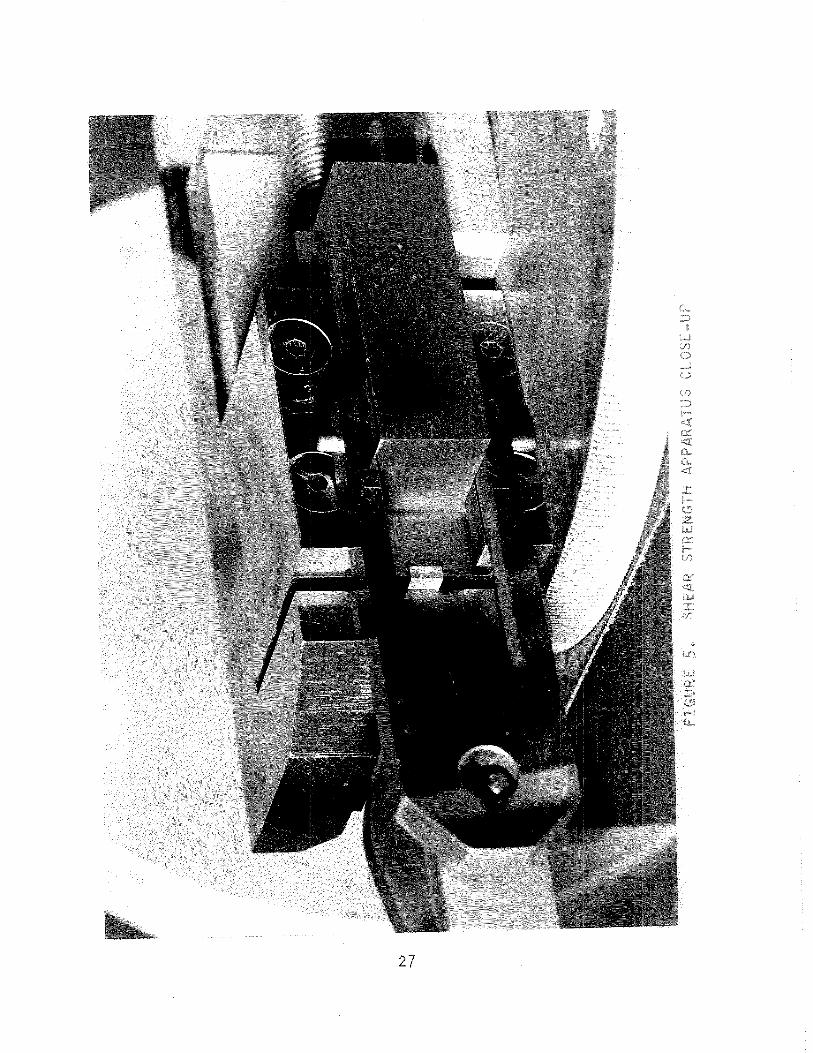

FIGURE 6. RESISTIVITY SAMPLE TEST CLOSE-UP
28


- c f s., fZGURL IC- IO? iGX iUUSN4L SECSiOk4 3F E,S, 3&4, WHITE, Ag, Ijfifin &MU;", ; g b P j - I I E , L l G k i T GRAY M b k 2


-lp L J--."---L-A ---- "!.--- ---J- 2 2 4 7 6 7 6 ,"* ni
J G
INCHES OF RING T R A V E L k RP LIGURE 13. NOISE QP-P) DURENG R U N - fN AT 158 E-'F'"lbi
3 5
%[wRr 14, Nfl'l;F (P-P) DURING PUN-EN AT' 55' 3 6


BRUSH EklIATEKIAL A ISL--ERLjSL-t @
60i?+j 5 ! LVEP Fi i N G S @ G & + B B - ~ U S ~ - I O
i i


-, .1.
C.? -*-
L
csa
KWQDE(lk44 P L A T E D iV


1
I 25431
I !
I
f lb 2c..;i c-U I LC1 "r--- 2 i c. Z 0 i ' j c2 -& i5t:\\
1 22 -- I Ci 6- - I
I --" 1 If" , -* I cat DI- "L*
4 I",.,, -1 h e ~
0 a

I 0 I ---- J --.- ~-.-'-.--L," ,-,*-
I 2 4 5 6' A . - . - % p L 'i -.--,* "---"--
i f" , # I"; r:A' , , 0 F R 1 pd G "'T F? A,\/ F' : ‘'14
i.. h... I .-" C\ 3raj, 3 ~ ~ j C ~ - ~ $ ~ ; ~ ~ ~ , , ; p $ ~ ~ t j ~ ; + ~ ~ y ~ s ~ ~ ~ - j - ~ - t i s
BT" C"*] W$hil 52


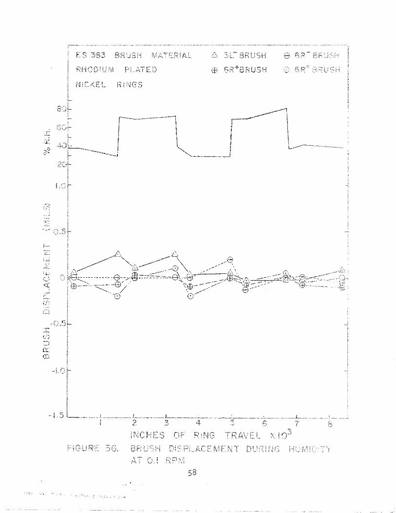


TABLE I1
DATA FROM 12% MoS2, 3% GRAPHITE, 85% Ag C O M P O S I T E S
( E S 383)
Shear Strengths, P S I
Transverse Normal Long.
AVG [7100]
Densi t y (Percen t Theo re t i ca l )
SAMPLE A 92 SAMPLE B 93
89 86 90 9 1
(90) (90) [90 I
6 Resi s t i v i t y (ohm i nches X 10- )
Transverse 2.5
Norma 1 2.2
L o n g i t u d i n a l 6.9
[ 3 -91
( SampleMean
[ ] L o t Mean
6 3

TABLE I11
DATA FROM 15% NbSe2, 3% GRAPHITE 82% Ag C O M P O S I T E S (E S 38L)
Shear Strengths, P S I Transverse Normal Longi t u d i n a l
L o t #I ~ o t #2 ~ o t #I ~ o t #2 ~ o t # I L o t # 2
Densi t y (Percent Theo re t i ca l )
L o t #1 L o t # 2 Sample A Sample B Sample A Sample B
8 7% 88% 91% 8 6% 85% 90% 92% 9 0% 9 1 % 9 2% 92% 9 2%
(88%) (90%) (92%) g 89%) [ 89% I [91%1
6 Resi s t i v i t y (ohm inches X 10' ) Transverse Normal Longi t u d i n a l
L o t #I L o t #2 L o t #I L o t #2 L o t # I L o t #2
SAMPLEA - - - 3 - 1 9.6 4.4 13.3 7 . 1 SAMPLEB 6.8 9 - 7 4 - 5 7 - 3 9.1 1 0 - 9
[ 6 - 8 1 [6.41 [ 7 - 1 1 [ 5 - 9 1 [ I 1 -21 [9,09
( ) - Sample Mean
[ ] - L o t Mean


APPENDIX A
COMPOSITE BRUSH FOR SPACE ENVIRONMENTS E S 3 8 3
1 - 0 Scope:
1.1 Th is s p e c i f i c a t i o n e s t a b l i s h e s the requirements fo r a composi t e brush t h a t must be s e l f l u b r i c a t i n g i n both space and ground env i ronments, I t i s in tended f o r power o r ins t rument grade brushes w i t h volumes l e s s t h a n 1 i n 3 -
1.2 A l l m a t e r i a l f u r n i s h e d under t h i s s p e c i f i c a t i o n m u s t con- form t o the standards h e r e i n descr ibed un less otherwi se s t a t e d on the drawing o r i n the Purchase Order,
2 -0 App l i cab le S p e c i f i c a t i o n s :
2.1 A N S I C 64.1-1970 (NEMBA CBl-1970) forms a p a r t o f t h i s s p e c i f i c a t i o n where a p p l i c a b l e and non-conf l i c t i n g ,
2.2 A N S I Z 23.1-1961 (ASTM E l l )
3.0 Requi rements:
3.1 Chemical Composi t i o n (wt .%) - Best commercial grade m a t e r i a l s s h a l l be used.
3.0 + 0.5% Graph i te (Na tu ra l , Ceylon o r Madagascar OrigTn) . Balance - f i n e s i l v e r
3 - 2 P a r t i c l e S ize
3.2.1 MoS2 - 100% of the p a r t i c l e s s h a l l pass through a 325 mesh ( 4 4 ~ ) screen.
3.2$2 Graph i te - 100% of the p a r t i c l e s s h a l l pass "chrouqn a 100 mesh ( 1 4 9 ~ ) screen and 50% s h a l l p a s s t h r o u g h a 325 mesh (44p,) screen.
3.2.3 Silver-Maximum o f 12% (wt.) s h a l l remain on 325 mesh screen; maximum of 1% (wt . ) s h a l l remain on a 200 mesh screen; 100% must pass through a 100 mesh screen.
3.3 Dens i ty :
Composi t e s h a l l be a t l e a s t as dense as 85% - 95% of the

3 t h e o r e t i c a l densi ty , i .e., g rea ter than 7-12 gram/cm ,
3.4 Backing:
When requi red by drawing,, a metal 1 i c backi ng s h a l l be incorpora ted i n t o the brush so t h a t i t may be s o l d e r e d , The backing cannot be formed by e l e c t r o p l a t i n g , There s h a l l be no apparent cracks or separat ion of t h e corn- posi t e and backing when the i n t e r f a c e i s viewed a t 50X,
3 - 5 Workmanship:
Brushes s h a l l be s t r u c t u r a l l y sound. A1 I brushes si-)all be f r e e from cracks, seams, voids, i nc lus ions , se t i o n and o ther de fec ts upon examination o f a samp 3 O X . The composi t e s h a l l be f r e e o f v i s i b l e corros ion products a t 30X.
3 - 6 Mic ros t ruc tu re :
Const i tuents o f the canposi t e sha l l be un i fo rm ly d i s - t r i b u t e d when a pol i shed sec t ion i s viewed a t 7 5 X , P a r t i c l e s s h a l l n o t have been d is lodged from edges o f the composi t es as a resu l t o f hand1 i n g a f t e r the forming operat ions. Metal 1 i c p a r t i c l e s shal 1 n o t have been d is lodged by normal meta l lograph ic g r i n d i n g and p o l i s h i n g operat ions. Bonding s h a l l be ev ident between m e t a l p a r t i c l e s .
3 - 7 Crys ta l I i n e S t ruc ture :
The lame1 l a r s t r u c t u r e o f the MoS or g raph i te s h a l l 2
n o t have been destroyed by the manufactur ing process,
3 -8 Cmposi t e Strength:
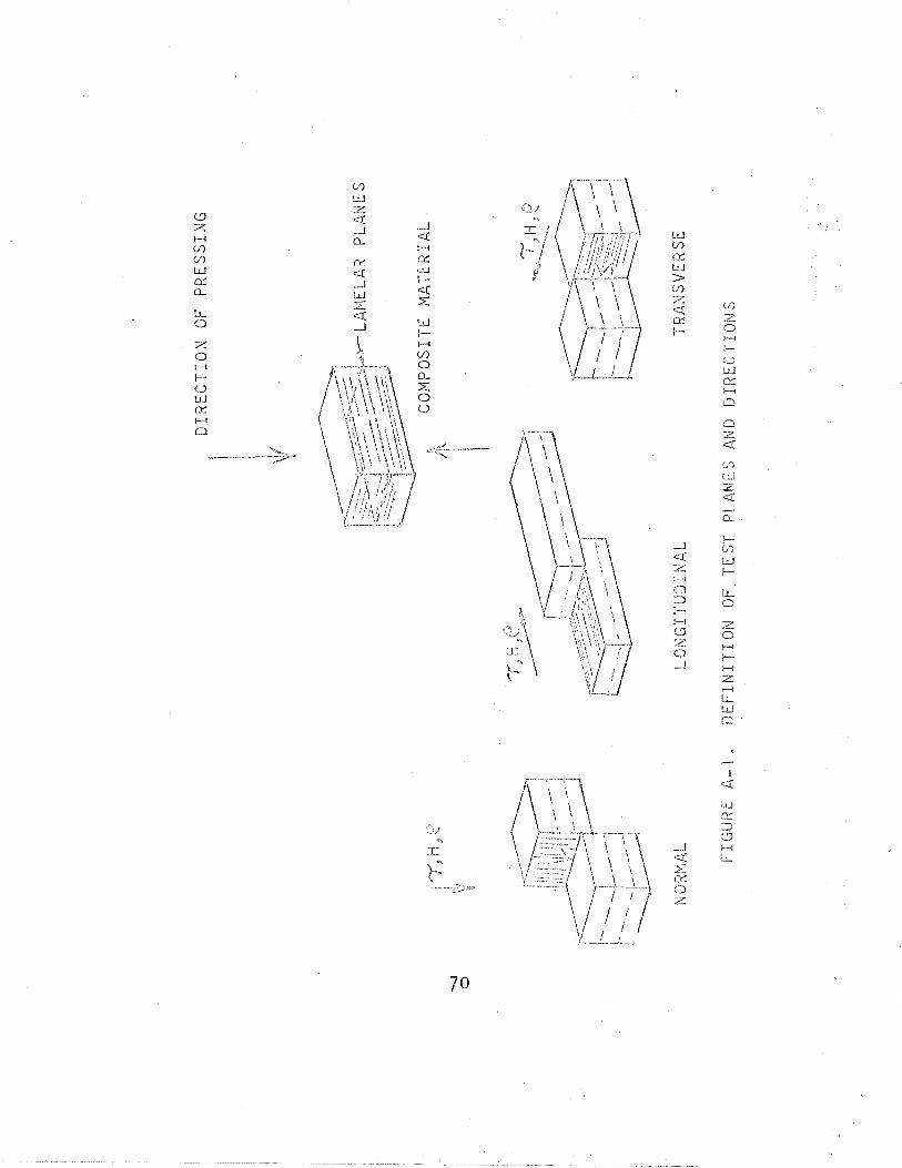
3.8.1 Normal, l o n g i t u d i n a l and t ransverse shear planes s h a l l be as de f ined i n F igu re A - 1 ,
3.8.2 The shear s t reng th i n the t ransverse p lane shall be 6500 ps i , minimum.
3.8.3 The shear s t reng th i n the normal plane s h a l l be 4500 ps i , minimum.
3.8.4 The shear s t rength i n the l o n g i t u d i n a l p l a n e s h a l l be 2700 ps i , minimum,
3.9 Processing:
3 - 9 - 1 Lub r i can ts
No l u b r i c a n t s s h a l l be a p p l i e d to powders t h a t are n o t p a r t o f the d e s i r e d composite ( i , e , , MoS2 and g r a p h i t e ) . No s u l f u r i z e d l u b r i c a n t s
may be used on the fo rming d ies .
3.9.2 Scrap m a t e r i a l s h a l l n o t be used i n the manu- f a c t u r e of t h i s product ,
3,9.3 No b i n d e r s s h a l l be used.
3.9.4 Processing s h a l l be such as t o prevent decom- p o s i t i o n o f l u b r i c a n t s ,
3 -10 S p e c i f i c Resistance: 9 x 1 0 ~ ~ Ohm-Inches (maximum)
4.0 I n s p e c t i o n and Test ing:
4.1 The vendor s h a l l perform, o r have performed a t l e a s t these minimum t e s t s t o i n s u r e c c n f o r m i t y t o t h i s standard,
4.1 - 1 Visual i n s p e c t i o n a t 30X t o i n s u r e compliance w i t h Paragraph 3.5 o f t h i s standard,
4 -1 -2 Check o f dimensions as de f i ned on Engineer ing Drawi ng.
3 4-1.3 Dete rmina t ion o f densi t y , g/cm , Backing m a t e r i a l s h a l l n o t be i n c l u d e d i n dens i t y cam- p u t a t i o n .
4.2 P o l y - S c i e n t i f i c may per fo rm any o r a1 1 of the fallawing t e s t s upon r e c e i p t of m a t e r i a l f u r n i s h e d to t h i s spec-8"- f i c a t i on.
4,2,1 Spect rographic Ana l ys i s (Paragraph 3 , I )
4.2.2 Dimensional check (Engineer ing Drawing),
4.2.3 M ic roscop ic exami n a t i cn (paragraph 3.4 a n d 3 -5)
4.2,4 Metal l og raph i c examinat ion (Paragraph 3,k and 3 -6)
4.2.5 Measurement o f Dens i ty (Paragraph 3 - 3 1
4.2.6 Measurement of composite s t r e n g t h (Paragraph 3*83
4,2,7 X-ray d i f f r a c t i o n a n a l y s i s (Paragraph 3 - 7 1

5.0 Package and De l ivery :
5.1 The m a t e r i a l f u rn i shed under t h i s s p e c i f i c a t i on s h a l I be packed i n such a way as t o i nsu re conformi ty to the standards he re in descr ibed upon a r r i v a l a t Poly- S c i e n t i f i c .
5.2 Packing should be such t h a t danger of darnagjng u p c n unpacking i s a minimum.
5.3 D e l i v e r i e s s h a l l be made w i t h due precaut ion to i n s u r e safe, r a p i d and economic t r a n s f e r ,
6.0 Ordering:
6.1 An order for ma te r ia l under t h i s speci f icat ion1 siqal? i nc lude a P o l y - S c i e n t i f i c Engineering Drawing w i t h a l l to lerances d e f i ned and a copy o f t h i s s p e c i f i c a t i on,
6.2 Orders shal I spec i f y app l i cab le r e v i s i o n o f specifica- t i o n .

APPENDIX B
COMPOSITE BRUSH FOR SPACE ENVIRONMENTS ES384
1.0 Scope:
1 . I Th is s p e c i f i c a t i o n e s t a b l i shes the requirements for a composite brush t h a t must be s e l f l u b r i c a t i n g i n beeh space and ground environments, I t i s in tended for power o r ins t rument grade brushes w i t h volumes l e s s than 1 i n3 ,
1.2 A1 1 m a t e r i a l f u r n i s h e d under t h i s s p e c i f i c a t i o n musr conform t o t he standards h e r e i n descr ibed un less o the r - w i se s t a t e d on the drawing o r i n t h e Purchase O r d e r ,
2.0 A p p l i c a b l e S p e c i f i c a t i o n s :
2.1 A N S I C 64.1-1970 (NEMBA CB1-1970) forms a p a r t o f t h i s s p e c i f i c a t i o n where a p p l i c a b l e and n o n - c o n f l i c t i n g , ,
2.2 A N S I Z 23.1-1961 (ASTM E l l )
3 -0 Regui remen ts :
3.1 Chemical Composi t i o n (wt.%) - Best commercial grade m a t e r i a l s s h a l l be used.
3 -0 + 0.5% Graphi t e (Na tu ra l Ceylon o r Madagascar O r i gTn) . Ba 1 ance - f i n e s i 1 ver
3.2 P a r t i c l e S ize
3.2.1 NbSe2 - 100% o f the p a r t i c l e s s h a l l pass thrcugh a 325 mesh (44p,) screen.
3.2,2 Graph i te - 100% o f the p a r t i c l e s s h a l l pass through a 100 mesh (14gy) screen and 50% sha l l pass through a 325 mesh (44p,) screen,
3.2.3 S i l v e r - Maximum o f 12% (wt, ) s h a l l remain cn 325 mesh screen; maximum of 1% (wt . ) s h a l l remain on a 200 mesh screen; 100% must pass through 2
100 mesh screen.

3.3 Dens i ty
Composite s h a l l be a t l e a s t as dense as 85% - 95% o f t he t h e o r e t i c a l dens i ty , i ,e., g rea te r than 7-18 gram/cm3.
3,4 Backing
When r e q u i r e d by drawing a metal I i c back ing s h a l l be i nco rpo ra ted i n t o the brush so t h a t i t may be soldered, The back ing cannot be formed by e l e c t r o p l a t i n g , There s h a l l be no apparent c racks o r separa t ion o f t h e GOTI- pos i t e and back ing when the i n t e r f a c e i s viewed a t 50X,
3.5 Workmanship
Brushes s h a l l be s t r u c t u r a l l y sound, A 1 1 brushes shall be f r e e f rom cracks, seams, vo ids, i n c l u s i o n s , segrega- t i o n and other de fec t s upon examinat ion o f a sample a t 30X. The composi t e s h a l l be f r e e o f v i s i b l e co r ros ion p roduc ts a t 30X.
3 - 6 M i c r o s t r u c t u r e
C o n s t i t u e n t s o f t h e composi t e s h a l l be un i form1 y di s - t r i b u t e d when a p o l i s h e d s e c t i o n i s viewed a t 75X- P a r t i c l e s s h a l l n o t have been d is lodged from edges s f the composi t e s as a r e s u l t o f hand l i ng a f t e r the forming opera t ions , Bonding s h a l l be e v i d e n t bletween meta l p a r t i c l e s .
3.7 C r y s t a l 1 i n e S t r u c t u r e
The lame1 l a r s t r u c t u r e o f t h e NbSe o r g r a p h i t e s h a l l 2
n o t have been dest royed by t h e manufactur ing process,
3,8 Composi t e S t reng th
3.8-1 Normal, l o n g i t u d i n a l and t ransverse shear plalnes s h a l l be as d e f i ned i n F i g u r e B - 1 .
3.8.2 The shear s t reng th i n t he t ransverse plane s h a l l be 7000 ps i , minimum
3.8.3 The shear s t reng th i n the normal p lane s h a l l be 6600 ps i , minimum,
3.8.4 The shear s t r e n g t h i n the l o n g i t u d i n a l p lane shal I be 5200 ps i , minimum,

3 -9 Processing
3-9.1 L u b r i c a n t s
No l u b r i c a n t s s h a l l be a p p l i e d t o powders c h a t a r e n o t p a r t o f t h e d e s i r e d composite (i ,e,, NbSe2 and graphi t e ) . No s u l f u r i z e d l ub r i c a n t s
may be used on the fo rming d ies .
3.9-2 Scrap m a t e r i a l s h a l l n o t be used i n the manufac- t u r e o f t h i s product ,
3.9.3 No b i n d e r s s h a l l be used,
3 -9.4 Processing s h a l l be such as t o p reven t decmpos i - t i o n o f l u b r i c a n t s ,
3.10 S p e c i f i c Resi stance: 1 2 ~ 1 0 - ~ Ohm-Inches (Maximum)
4,O I n s p e c t i o n and Tes t ing
4 - 1 The vendor s h a l l perform, o r have performed a t least these minimum t e s t s t o i n s u r e conformi t y t o t h i s standard.
4.1.1 V isua l i n s p e c t i o n a t 30X t o i n s u r e c m p l i a n c e w i t h Paragraph 3.5 o f t h i s standard.
4.1 - 2 Check of dimensions as de f i ned on Engineer ing Drawi ng .
3 4.1 ,3 Determinat ion o f dens i ty , g/cm . Backirag m a t e r i a l shal I n o t be i n c l u d e d i n d e n s i t y corn- p u t a t i o n ,
4.2 P o l y - S c i e n t i f i c may perform any o r a l l o f t he following t e s t s upon r e c e i p t of m a t e r i a l f u r n i s h e d t o t h i s speci - f i c a t i m ,
4,2.1 Spect rographic Ana l ys i s (Paragraph 3 - 1 )
4.2.2 Dimensional check (Engineer ing Drawing)
4.2.3 M ic roscop ic examinati on (Paragraph 3 -4 and 3 -5)
4 - 2 - 4 Meta l 1 ographic examinat ion (Paragraph 3 -4 and 3.6)
4.2-5 Measurement of d e n s i t y (Paragraph 3.3)

4.2.6 Measurement o f composite s t reng th (paragraph 3-8)
4-2.7 X-ray d i f f r a c t i o n a n a l y s i s (Paragraph 3 . 7 )
5.0 Package and D e l i v e r y :
5.1 The m a t e r i a l f u r n i s h e d under t h i s s p e c i f i c a t i o n s h a l l be packed i n such a way as t o i n s u r e con fo rm i t y t o the standards h e r e i n descr ibed upon a r r i v a l a t Po ly - S c i e n t i f i c .
5.2 D e l i v e r i e s s h a l l be made w i t h due p recau t ion t o insure. safe, r a p i d and economi c t r a n s f e r .
6.0 Order ing:
6.1 An order f o r m a t e r i a l under t h i s s p e c i f i c a t i o n s h a l l i n c l u d e a P o l y - S c i e n t i f i c Engineer ing Drawing w i t h a1 l to le rances de f i ned and a copy o f t h i s s p e c i f i c a t i o n ,
6.2 Orders s h a l l s p e c i f y a p p l i c a b l e r e v i s i o n o f specif-8" -. c a t i o n .


REFERENCES -
1, Glossbrenner, E. W., I t s l i p Ring Assembl i e s f o r Spacecraf t Devicest t , Proceedings From Seminar on S l i d ing E l e c t r i c a l Contacts I n Vacuum And Space, Sponsored by V i r g i n i a Po l y techn i c I n s t i t u t e and P o l y - S c i e n t i f i c D i v i s i o n , Litton I n d u s t r i e s , October 1, 1969,
2. Mayer, R , W., i tEva lua t ion o f S l i p Rings f o r Communication Sate1 l i t e App l i ca t ions i1 , B a l l B ro the rs Research Corporat ion, Report # ~ 6 9 - 0 7 , December 23, 1969.
3. Pent1 i c k i , C. J. and Glossbrenner, E, W e , [(The Tes t i ng o f Contact M a t e r i a l s f o r S l i p Ring And Brushes For Space Appl i c a t i onit t o be presented a t t he Seventeenth Annual Holm Seminar on E l e c t r i c Con t a c t Phenomena.
Related Documents