IEEE TRANSACTIONS ON VEHICULAR TECHNOLOGY, VOL. 41, NO. 3, AUGUST 1992 231 Effects of Radio Propagation Path Loss on DS-CDMA Cellular Frequency Reuse Efficiency for the Reverse Channel Theodore S. Rappaport, Senior Member, IEEE, and Laurence B. Milstein, Fellow, IEEE Abstract-Analysis techniques that quantitatively describe the impact of propagation path loss and user distributions on wireless direct-sequence code-division multiple-access (DS-CDMA)spread spectrum systems are presented. First, conventional terrestrial propagation models which assume a d4 path loss law are shown to poorly describe modern cellular and personal communication system channels. Then, using both a two-ray propagation model and path loss models derived from field measurements, we an- alyze the impact of path loss on the frequency reuse efficiency of DS-CDMA cellular radio systems. Analysis is carried out for the reverse (subscriber-to-base)channel using a simple geometric modeling technique for the spatial location of cells, and inherent to the geometry is the ability to easily incorporate nonuniform spatial distributions of users and multiple layers of surrounding cells throughout the system. Our analysis shows the frequency reuse efficiency (F) of the reverse channel with a single ring of adjacent cells can vary between a maximum of 71% in d4 channels with a favorable distribution of users, to a minimum of 33% in d2 channels with a worst case user distribution. For three rings of adjacent users, F drops to 58% for the best d4 case, and 16% for the worst d2 case. Using the two-ray model, we show that F can vary over a wide range of values due to the fine structure of propagation path loss. The analysis techniques presented here can be extended to incorporate site-specific propagation data. I. INTRODUCTION IDESPREAD use of CDMA for personal wireless W communications is likely to occur over the next sev- era1 years. In 1990, more than a dozen experimental license applications were tendered by the FCC for U.S. wireless com- munication systems using direct-sequence spread spectrum code division multiple access (DS-CDMA). U.S. CDMA field trials are currently underway by major cellular and personal communications companies using existing cellular spectrum in the 800-900 MHz and 1.8 GHz bands. The virtues of spread spectrum in a frequency reuse mobile radio environment have been discussed by only a handful of researchers over the past two decades (see [1]-[3] for example), and in light of recent Manuscript received April 1, 1991; revised October 15, 1991. This work was supported in part by DARPAESTO and the Mobile and Portable Radio Research Group (MPRG) Industrial Affiliates Program at Virginia Tech, and the NSF IAJCRC for Ultra-High Speed Integrated Circuits and Systems at the University of California at San Diego. Portions of this paper were presented at GLOBECOM ‘90, San Diego, CA. T. S. Rappaport is with the Mobile and Portable Radio Research Group, Bradley Department of Electrical Engineering, Virginia Polytechnic Institute and State University, Blacksburg, VA 24061-0111. L. B. Milstein is with the Department of Electrical and Computer Engi- neering, University of California, La Jolla, CA 92093-0407. IEEE Log Number 9200218. claims that CDMA could afford several times more capacity than other access techniques, analyses and simulation methods that accurately predict the capacity of CDMA systems in real world propagation environments are warranted. This paper studies one quantitative cellular performance measure: frequency reuse efficiency on the reverse (subscriber- to-base) channel of a CDMA cellular system that employs total frequency reuse. That is, we analyze the performance of a cellular system that allows all users in all cells to share the same reverse channel carrier frequency. In our work, we model a cellular radio system by using a concentric circle geometry that easily accommodates various distributions on the number or location of users within cells. Within each cell, ideal power control is assumed on the reverse channel, so that within a cell of interest, the same power level is received at the base from all subscribers within that cell. Subscribers in other cells are power-controlled within their own cell, and it is their radiated power that propagates as interference to the base station receiver in the cell of interest. This interference raises the noise level, and thereby reduces the number of users that can be supported at a specified average performance level. Holtzman [9] has shown how imperfect power control in the subscriber unit degrades the frequency-reuse efficiency of a CDMA cellular system. However, except for [ll], we are not aware of analyses that quantitatively describe how propagation path loss or user distributions affect the frequency reuse efficiency of such a system. As is shown subsequently, both propagation path loss and distribution of users can greatly impact frequency reuse efficiency of CDMA, even with perfect power control. This paper is organized into five sections. Section I1 presents a brief overview of propagation models and demonstrates with both the classic two-ray model and measured data how modern cellular systems undergo path loss that increases with distance to the second or third power, as opposed to the commonly used d4 model. For emerging microcellular systems, we propose a path loss law that incorporates a close-in free space reference power level to which all further users are referenced. Section I11 presents a frequency reuse analysis technique that uses concentric circles to model the location of adjacent cells, as well as the distribution of users within each cell. We also show how the concentric circle geometry can be equated to the conventional hexagonal geometry used in [l], [3]. In Section IV, we use this analysis technique in conjunction with path loss models developed in Section I1 to arrive at reverse channel 0018-9545/92$03.00 0 1992 IEEE

Welcome message from author
This document is posted to help you gain knowledge. Please leave a comment to let me know what you think about it! Share it to your friends and learn new things together.
Transcript
IEEE TRANSACTIONS ON VEHICULAR TECHNOLOGY, VOL. 41, NO. 3, AUGUST 1992 23 1
Effects of Radio Propagation Path Loss on DS-CDMA Cellular Frequency Reuse
Efficiency for the Reverse Channel Theodore S. Rappaport, Senior Member, IEEE, and Laurence B. Milstein, Fellow, IEEE
Abstract-Analysis techniques that quantitatively describe the impact of propagation path loss and user distributions on wireless direct-sequence code-division multiple-access (DS-CDMA) spread spectrum systems are presented. First, conventional terrestrial propagation models which assume a d4 path loss law are shown to poorly describe modern cellular and personal communication system channels. Then, using both a two-ray propagation model and path loss models derived from field measurements, we an- alyze the impact of path loss on the frequency reuse efficiency of DS-CDMA cellular radio systems. Analysis is carried out for the reverse (subscriber-to-base) channel using a simple geometric modeling technique for the spatial location of cells, and inherent to the geometry is the ability to easily incorporate nonuniform spatial distributions of users and multiple layers of surrounding cells throughout the system. Our analysis shows the frequency reuse efficiency ( F ) of the reverse channel with a single ring of adjacent cells can vary between a maximum of 71% in d4 channels with a favorable distribution of users, to a minimum of 33% in d2 channels with a worst case user distribution. For three rings of adjacent users, F drops to 58% for the best d4 case, and 16% for the worst d2 case. Using the two-ray model, we show that F can vary over a wide range of values due to the fine structure of propagation path loss. The analysis techniques presented here can be extended to incorporate site-specific propagation data.
I. INTRODUCTION IDESPREAD use of CDMA for personal wireless W communications is likely to occur over the next sev-
era1 years. In 1990, more than a dozen experimental license applications were tendered by the FCC for U.S. wireless com- munication systems using direct-sequence spread spectrum code division multiple access (DS-CDMA). U.S. CDMA field trials are currently underway by major cellular and personal communications companies using existing cellular spectrum in the 800-900 MHz and 1.8 GHz bands. The virtues of spread spectrum in a frequency reuse mobile radio environment have been discussed by only a handful of researchers over the past two decades (see [1]-[3] for example), and in light of recent
Manuscript received April 1, 1991; revised October 15, 1991. This work was supported in part by DARPAESTO and the Mobile and Portable Radio Research Group (MPRG) Industrial Affiliates Program at Virginia Tech, and the NSF IAJCRC for Ultra-High Speed Integrated Circuits and Systems at the University of California at San Diego. Portions of this paper were presented at GLOBECOM ‘90, San Diego, CA.
T. S. Rappaport is with the Mobile and Portable Radio Research Group, Bradley Department of Electrical Engineering, Virginia Polytechnic Institute and State University, Blacksburg, VA 24061-0111.
L. B. Milstein is with the Department of Electrical and Computer Engi- neering, University of California, La Jolla, CA 92093-0407.
IEEE Log Number 9200218.
claims that CDMA could afford several times more capacity than other access techniques, analyses and simulation methods that accurately predict the capacity of CDMA systems in real world propagation environments are warranted.
This paper studies one quantitative cellular performance measure: frequency reuse efficiency on the reverse (subscriber- to-base) channel of a CDMA cellular system that employs total frequency reuse. That is, we analyze the performance of a cellular system that allows all users in all cells to share the same reverse channel carrier frequency. In our work, we model a cellular radio system by using a concentric circle geometry that easily accommodates various distributions on the number or location of users within cells. Within each cell, ideal power control is assumed on the reverse channel, so that within a cell of interest, the same power level is received at the base from all subscribers within that cell. Subscribers in other cells are power-controlled within their own cell, and it is their radiated power that propagates as interference to the base station receiver in the cell of interest. This interference raises the noise level, and thereby reduces the number of users that can be supported at a specified average performance level.
Holtzman [9] has shown how imperfect power control in the subscriber unit degrades the frequency-reuse efficiency of a CDMA cellular system. However, except for [ll], we are not aware of analyses that quantitatively describe how propagation path loss or user distributions affect the frequency reuse efficiency of such a system. As is shown subsequently, both propagation path loss and distribution of users can greatly impact frequency reuse efficiency of CDMA, even with perfect power control.
This paper is organized into five sections. Section I1 presents a brief overview of propagation models and demonstrates with both the classic two-ray model and measured data how modern cellular systems undergo path loss that increases with distance to the second or third power, as opposed to the commonly used d4 model. For emerging microcellular systems, we propose a path loss law that incorporates a close-in free space reference power level to which all further users are referenced. Section I11 presents a frequency reuse analysis technique that uses concentric circles to model the location of adjacent cells, as well as the distribution of users within each cell. We also show how the concentric circle geometry can be equated to the conventional hexagonal geometry used in [l], [3]. In Section IV, we use this analysis technique in conjunction with path loss models developed in Section I1 to arrive at reverse channel
0018-9545/92$03.00 0 1992 IEEE
232 IEEE TRANSACTIONS ON VEHICULAR TECHNOLOGY, VOL. 41, NO. 3, AUGUST 1992
frequency reuse factors for a variety of propagation channels and user distributions. Section V summarizes the results of this work.
11. PROPAGATION
Accurate propagation modeling is vital for accurately pre- dicting the coverage and capacity of cellular radio systems. This is particularly true in evolving CDMA systems, since capacity is interference limited instead of power limited. Unlike conventional cellular radio system design which strives for excellent base station coverage in each cell, and then relies on judicious frequency management within a service area to mitigate cochannel interference, CDMA requires no frequency planning.'
While more recent work has considered small scale fading and imperfections in power control [15], in this work we use a simple small scale shadow fading model, neglect frequency- selective fading effects, and consider average path loss as a function of distance between base and mobile. Thus, we consider very slow flat fading channels with no resolvable multipath components. Since we are interested in analyzing the average frequency reuse efficiency of DS-CDMA systems in different path loss environments, the use of an average distance-dependent path loss model that neglects small scale shadow fading of individual users is adopted. That is, we sim- plify the analysis by assuming the total received power from N independent transmitters located at a radial distance T from the base receiver is, on average, N times the power from a single subscriber at T as predicted by the path loss model. This is a valid approach for the case of any symmetric shadowing distribution about the mean path loss, and a sufficiently large number of users. However, field measurements often show that shadow fading is log-normally distributed about the mean, which is not a symmetric distribution in terms of absolute power levels. Thus, while our analysis offers insight into how different cell sizes and different path loss models impact frequency reuse, our analysis does not address second-order shadowing effects. The simulation methodology in Section IV, however, can be adopted to include shadowing effects and is described subsequently.
First, we consider the classic two-ray model (direct path and single ground reflection) to see how received signal power varies with distance between transmitter and receiver due to a simple site-specific channel model. Then, we show measured data which agrees with a path loss power law of distance to the nth power, where n is a constant that ranges between 2 and 4.
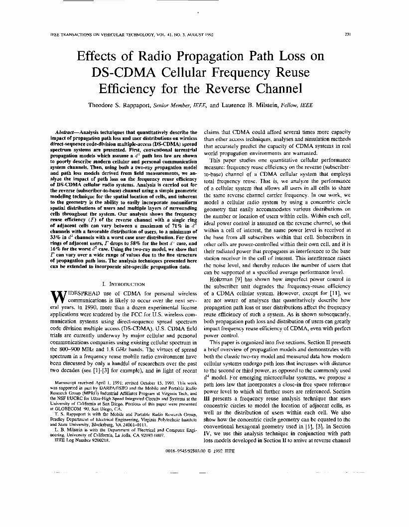
Fig. 1 illustrates the classic two-ray propagation geometry that is used to model long-haul terrestrial microwave systems. There is a P radian phase shift induced by the ground reflection [lo]. This geometry does not consider other multipath or shadowing effects other than the ground reflected path. The in-
' CDh4A can exploit resolvable multipath components using path diversity and combining (RAKE reception); however, energy in multipath components in frequency selective channels can add to the interference level of the system. Urban wide-band measurements have shown that channels can induce many delayed multipath components that have strengths within 10 dB of the strongest signal [4],[5]. We do not consider the effect of frequency-selective fading in this analysis.
Fig. 1. Geometry for the two-ray (ground reflection) path loss model.
dividual LOS and ground reflected components are considered to have amplitudes which do not vary with time, and which individually undergo free space propagation as the separation distance (d ) between transmitter and receiver increases. The path loss is due to the envelope produced as the RF phases of each signal component vectorially combine in different ways as the mobile travels over space. We shall show shortly that in real channels which have many multipath components that fade and are shadowed [4], [SI, measured large scale path loss is comparable to those predicted from the simple geometry in Fig. 1, so long as a free space reference distance close to the transmitter is used [ll], [14].
Historically, the geometry in Fig. 1 has been used to describe the large scale site-specific propagation phenomenon observed in terrestrial and analog cellular systems, systems which have deliberately aimed to maximize coverage distance. Traditional use of the two-ray model predicts the received signal several kilometers away, based on a received signal level at 1 km separation. It is only recently that the two- ray model of Fig. 1 has been used to model path loss in microcellular channels where small coverage areas are desired to increase frequency reuse, and thus capacity [6], [ 141. Measurements in cellular and microcellular channels that provide log-distance path loss models using reference distances closer than 1 km have also been reported recently [7].
At a distance T from a transmitting antenna, if an electric field intensity given by E = ( A / T ) c o s ( ~ T ~ ~ ) V/m (without ground reflection) is measured in free space, then for the two- ray model of Fig. 1, the received electric field envelope at an antenna located at a distance r from the transmitting antenna is given by
where
4 ~ h t h , E-
X r ' for T >> hth, (2)
where ht is the height of the transmitter antenna in meters, h, is the height of the receiver antenna in meters, and X is the carrier wavelength in meters. Equation (1) assumes unity gain antennas at both transmitter and receiver.2 From (l), the
*This analysis assumes that both the transmitter and receiver antennas offer equal gains to the direct and ground-reflected components. For very small values of T, say less than a few tens of meters, ( 1 x 4 ) are not valid and the true antenna gain patterns must be considered [14]. It can be shown that at very close range, the path loss is dominated by the direct path. The authors thank Dr. Joseph Shapira for pointing this out.
RAPPAPORT AND MILSTEIN: CELLULAR FREQUENCY REUSE EFFICIENCY 233
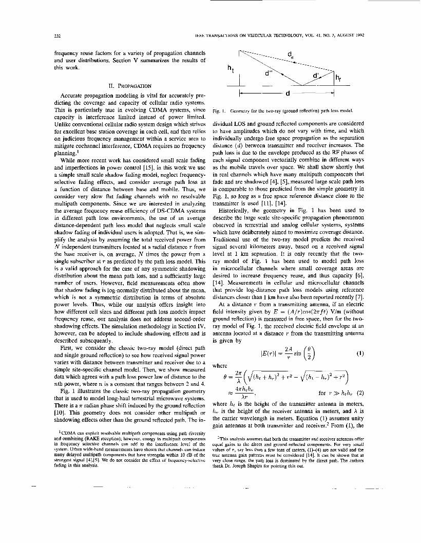
TABLE I EXPERIMENTAL RESULIS OF WIDE-BAND PROPAGATION MEASUREMENTS IN SIX CELLULAR AND MICROCELLULAR
CHANNELS, BEST-FIT EXPONENT VALUES WERE COMPUTED ASSUMING A 100 m FREE SPACE REFERENCE DISTANCE Antenna Height n Maximum T-R Maximum rms Maximum Excess U
Separation Delay Spread Delay Spread 10 dB (m) (dB) (km) (PSI (PSI
Hamburgh 40 2.5 8.3 8.5 2.7 7.0 Stuttgart 23 2.8 9.6 6.5 5.4 5.8 Dusseldorf 88 2.1 10.8 8.5 4.0 15.9 Frankfurt (PA Building) 20 3.8 7.1 1.3 2.9 12.0 Frankfurt (Bank Building) 93 2.4 13.1 6.5 8.3 18.4 Kronbreg 50 2.4 8.5 10.0 19.6 51.3 All (100 m) 2.7 11.8 10.0 19.6 51.3 All (1 km) 3.0 8.9 10.0 19.6 51.3
received power is proportional to IE(r)I2 , and is given by
P ( T ) c( IE(r)I = - 4T:2(f - - - f cose ) . (3a)
When the value of A is known exactly, (3a) can be used to determine the absolute electric field (and thus absolute received power) as a function of the transmitter-receiver (T- R) separation distance T . The value of A in (3a) represents the measured electric field intensity at a convenient close-in distance, which is in the far field of the transmitting antenna, i.e., the measured electric field at a distance of 1 m, 100 m, 1 km, or some other convenient distance from the transmitting antenna.
The absolute received power level as a function of T is given exactly by
P ( T ) = IE(r)12 * A,/377 (3b)
where A , is the effective area of the receiver antenna, 377 R is the intrinsic impedance of free space, and A , is proportional to the receiver antenna gain [12].
When the T-R separation, T , is much greater than hth, , (3a) simplifies to
(4)
The denominator of (4) suggests that power increases as distance to the fourth power, and this is sometimes quoted in the literature. This is also the propagation law assumed in [3]. It must be noted, though, that (4) is an asymptotic relationship, which holds when T is typically much larger than 1 km. As shown subsequently, (4) does not relate the actual power of distant users to close-in users, although such a model is required for meaningful CDMA system analysis and design. Rather, (4) relates the received power of very distant users to other distant users. Thus, we propose the use of a close-in free-space reference distance, a, to which the received signal strengths at all farther distances may be compared.
A. Path Loss Models The geometry in Fig. 1 and the propagation equations
( 1 H 3 ) can be used to determine the distance-dependence of received power, and consequently the distance-dependence of an appropriate power law exponent for a two-ray flat-fading
channel. If we let a denote the distance between the closest subscriber and the base station, and let a be the distance at which A in (3a) is measured, then the power of all subscribers with T-R separations greater than a can be related to the known power at a.
Consider DS-CDMA where all in-cell transmitting sub- scribers are power controlled to have identical signal levels P, arriving at the base receiver. If we assume all subscribers are located at least a m away from the base station, and further assume that subscribers at a have transmitted power P(a) , the transmitted power P ( T ) of a subscriber at distancer(r > a) can be described by a log-distance model [5]
For this work, we assume that P ( a ) is controlled based on a free space propagation channel (direct path only) between the base and all subscribers located a m from the transmitter. The free space channel assumption for the base to the closest subscriber is not strict, and in real channels will not necessarily be valid since it depends on the antenna heights and patterns, and multipath. However, for analysis of CDMA frequency reuse, it is necessary to relate all of the power levels to some known power level P(a) , which we consider to be caused by close-in free space propagation. For an interference limited system, one in fact may use any reasonable constant for P ( c x ) . ~
The propagation path loss model in (5a) implies that if P (a ) i s specified and P ( T ) is known, either from a model (i.e., (3)) or measurement, then the path loss exponent n depends on both a and T . This can be seen be rewriting (5a)
For modern systems, a is on the order of several tens of meters, particularly in microcellular systems within heavily populated areas. Once a and P(a)are specified, the system path loss PL in decibels, referenced to the closest user from the base
3The actual value of P(a) does have system design ramifications, since the absolute power levels will determine coverage areas. In this paper, we assume that base stations are suitably spaced so that the cellular system is not limited by link budget, but by interference.
234 IEEE TRANSACTIONS ON VEHICULAR TECHNOLOGY, VOL. 41, NO. 3, AUGUST 1992
Path Loss and Path Loss Exponent vs T-R Separation Relative to 100 m free space path
Path Loss (two-ray model) n Path Loss Exponent - r
Path Loss and Path Loss Exponent vs T-R Separation Relative to 100 m free space path
Hamburg
Path Loss (two-ray model) n Path Loss Exponent
5 50
4 40
3 30
2 20
1 10
0 0
a W
0
VI a e E 0 - Y
z D VI VI 0 2
m v
f a
0.1 1 10 T-R Separation (km)
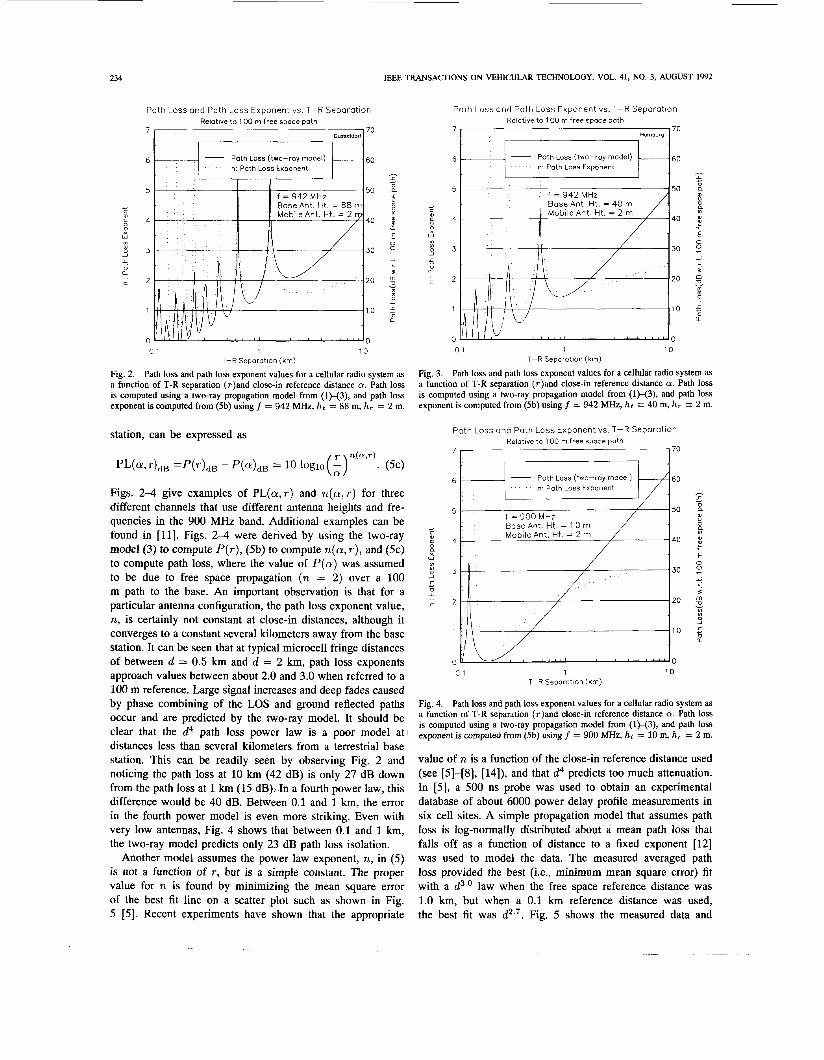
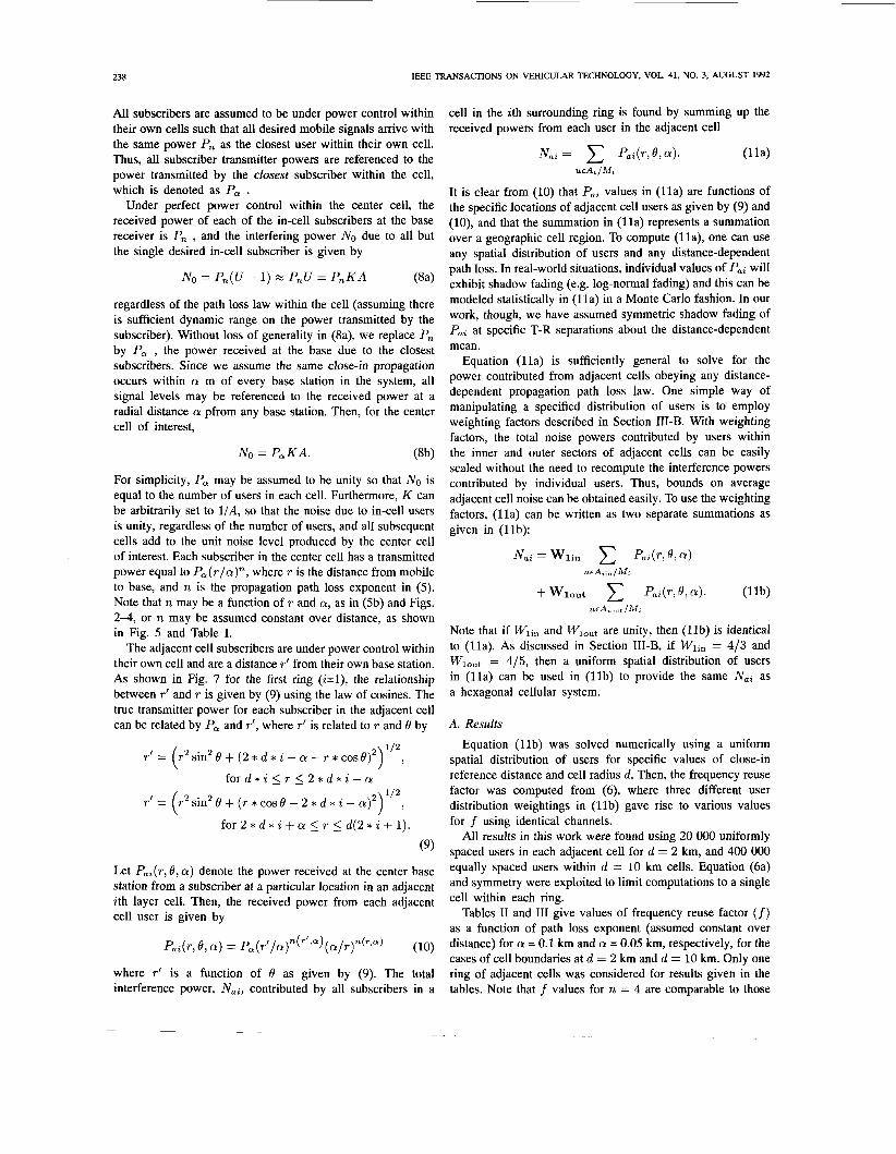
Fig. 2. Path loss and path loss exponent values for a cellular radio system as a function of T-R separation (r)and close-in reference distance a. Path loss is computed using a two-ray propagation model from (1)-(3), and path loss exponent is computed from (5b) using f = 942 MHz, ht = 88 m, h, = 2 m.
station, can be expressed as
Figs. 2-4 give examples of PL(cr,r) and n ( a , r ) for three different channels that use different antenna heights and fre- quencies in the 900 MHz band. Additional examples can be found in [ l l ] . Figs. 2-4 were derived by using the two-ray model (3) to compute P(r) , (5b) to compute n (a , T), and (5c) to compute path loss, where the value of P ( a ) was assumed to be due to free space propagation (n = 2) over a 100 m path to the base. An important observation is that for a particular antenna configuration, the path loss exponent value, n, is certainly not constant at close-in distances, although it converges to a constant several kilometers away from the base station. It can be seen that at typical microcell fringe distances of between d = 0.5 km and d = 2 km, path loss exponents approach values between about 2.0 and 3.0 when referred to a 100 m reference. Large signal increases and deep fades caused by phase combining of the LOS and ground reflected paths occur and are predicted by the two-ray model. It should be clear that the d4 path loss power law is a poor model at1 distances less than several kilometers from a terrestrial base station. This can be readily seen by observing Fig. 2 and noticing the path loss at 10 km (42 dB) is only 27 dB down from the path loss at 1 km (15 dB): .In a fourth power law, this difference would be 40 dB. Between 0.1 and 1 km, the error in the fourth power model is even more striking. Even with very low antennas, Fig. 4 shows that between 0.1 and 1 km, the two-ray model predicts only 23 dB path loss isolation.
Another model assumes the power law exponent, n, in (5) is not a function of T, but is a simple constant. The proper value for n is found by minimizing the mean square error of the best fit line on a scatter plot such as shown in Fig. 5 [5]. Recent experiments have shown that the appropriate
0.1 1 10 T-R Separotion (km)
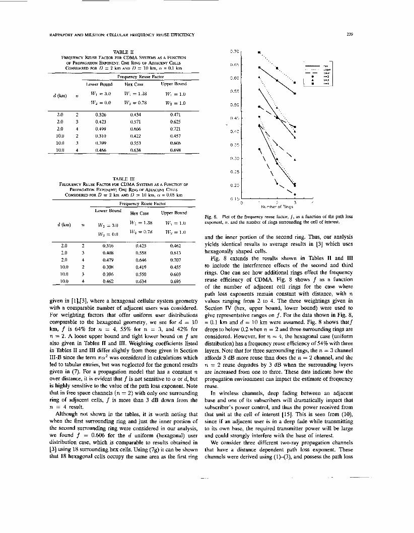
Fig. 3. Path loss and path loss exponent values for a cellular radio system as a function of T-R separation (r)and close-in reference distance a. Path loss is computed using a two-ray propagation model from (1)-(3), and path loss exponent is computed from (5b) using f = 942 MHz, ht = 40 m, h,
Path Loss and Path Loss Exponent vs T-R Separation Relative to 100 m free space path
7 70
6 60
5 50
4 40
3 30
2 20
1 10
0 0 0 1 1 10
T-R Separotion (km)
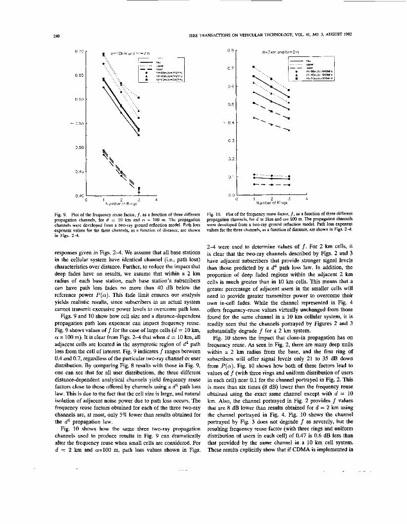
Fig. 4. Path loss and path loss exponent values for a cellular radio system as a function of T-R separation (r)and close-in reference distance a. Path loss is computed using a two-ray propagation model from (1)-(3), and path loss exponent is computed from (5b) using f = 900 MHz, ht = 10 m, h, = 2 m.
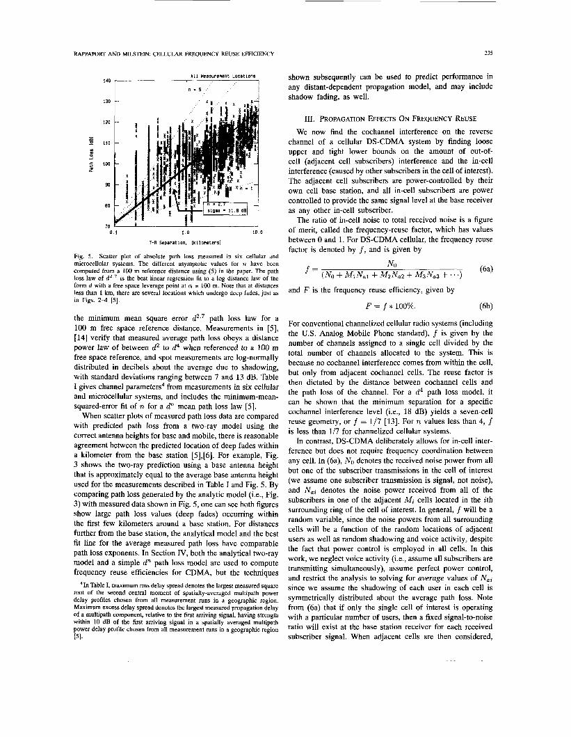
value of n is a function of the close-in reference distance used (see [5]-[8], [14]), and that d4 predicts too much attenuation. In [5], a 500 ns probe was used to obtain an experimental database of about 6000 power delay profile measurements in six cell sites. A simple propagation model that assumes path loss is log-normally distributed about a mean path loss that falls off as a function of distance to a fixed exponent [12] was used to model the data. The measured averaged path loss provided the best (i.e., minimum mean square error) fit with a d3.0 law when the free space reference distance was 1.0 km, but when a 0.1 km reference distance was used, the best fit was d2.7. Fig. 5 shows the measured data and
RAPPAPORT AND MILSTEIN: CELLULAR FREQUENCY REUSE EFFICIENCY 235
All Heasurement Locat ions 140 r I
I n - 5
130 c X r "
0 . 1 1 .0 10.0
T-R Separat ion. [ k i l o m e t e r s l
Fig. 5. Scatter plot of absolute path loss measured in six cellular dnd microcellular systems. The different asymptotic values for n have been computed from a 100 m reference distance using (5) in the paper. The path loss law of d2.? is the best linear regression fit to a log distance law of the form d with a free space leverage point at a = 100 m. Note that at distances less than 1 km, there are several locations which undergo deep fades, just as in Figs. 2 4 [5] .
the minimum mean square error d2.7 path loss law for a 100 m free space reference distance. Measurements in [SI, [I41 verify that measured average path loss obeys a distance power law of between d2 to d4 when referenced to a 100 m free space reference, and spot measurements are log-normally distributed in decibels about the average due to shadowing, with standard deviations ranging between 7 and 13 dB. Table I gives channel parameters4 from measurements in six cellular and microcellular systems, and includes the minimum-mean- squared-error fit of TI for a d" mean path loss law [SI.
When scatter plots of measured path loss data are compared with predicted path loss from a two-ray model using the correct antenna heights for base and mobile, there is reasonable agreement between the predicted location of deep fades within a kilometer from the base station [5],[6]. For example, Fig. 3 shows the two-ray prediction using a base antenna height that is approximately equal to the average base antenna height used for the measurements described in Table I and Fig. 5. By comparing path loss generated by the analytic model (i.e., Fig. 3) with measured data shown in Fig. 5, one can see both figures show large path loss values (deep fades) occurring within the first few kilometers around a base station. For distances further from the base station, the analytical model and the best fit line for the average measured path loss have comparable path loss exponents. In Section IV, both the analytical two-ray model and a simple d" path loss model are used to compute frequency reuse efficiencies for CDMA, but the techniques
41n Table I, maximum rms delay spread denotes the largest measured square root of the second central moment of spatially-averaged multipath power delay profiles chosen from all measurement runs in a geographic region. Maximum excess delay spread denotes the largest measured propagation delay of a multipath component, relative to the fist arriving signal, having strength within 10 dB of the first arriving signal in a spatially averaged multipath power delay profile chosen from all measurement runs in a geographic region PI.
shown subsequently can be used to predict performance in any distant-dependent propagation model, and may include shadow fading, as well.
111. PROPAGATION EFFECTS O N FREQUENCY REUSE We now find the cochannel interference on the reverse
channel of a cellular DS-CDMA system by finding loose upper and tight lower bounds on the amount of out-of- cell (adjacent cell subscribers) interference and the in-cell interference (caused by other subscribers in the cell of interest). The adjacent cell subscribers are power-controlled by their own cell base station, and all in-cell subscribers are power controlled to provide the same signal level at the base receiver as any other in-cell subscriber.
The ratio of in-cell noise to total received noise is a figure of merit, called the frequency-reuse factor, which has values between 0 and 1. For DS-CDMA cellular, the frequency reuse factor is denoted by f , and is given by
NO ( 6 4 (NO + MlNa1+ M2Na2 + M3Na3 + . .) f =
and F is the frequency reuse efficiency, given by
F = f * 100%. (6b)
For conventional channelized cellular radio systems (including the U.S. Analog Mobile Phone standard), f is given by the number of channels assigned to a single cell divided by the total number of channels allocated to the system. This is because no cochannel interference comes from within the cell, but only from adjacent cochannel cells. The reuse factor is then dictated by the distance between cochannel cells and the path loss of the channel. For a d4 path loss model, it can be shown that the minimum separation for a specific cochannel interference level (i.e., 18 dB) yields a seven-cell reuse geometry, or f = 1/7 [13]. For n values less than 4, f is less than 1/7 for channelized cellular systems.
In contrast, DS-CDMA deliberately allows for in-cell inter- ference but does not require frequency coordination between any cell. In (6a), NO denotes the received noise power from all but one of the subscriber transmissions in the cell of interest (we assume one subscriber transmission is signal, not noise), and N,i denotes the noise power received from all of the subscribers in one of the adjacent Mi cells located in the ith surrounding ring of the cell of interest. In general, f will be a random variable, since the noise powers from all surrounding cells will be a function of the random locations of adjacent users as well as random shadowing and voice activity, despite the fact that power control is employed in all cells. In this work, we neglect voice activity (i.e., assume all subscribers are transmitting simultaneously), assume perfect power control, and restrict the analysis to solving for average values of Nai since we assume the shadowing of each user in each cell is symmetrically distributed about the average path loss. Note from (6a) that if only the single cell of interest is operating with a particular number of users, then a fixed signal-to-noise ratio will exist at the base station receiver for each received subscriber signal. When adjacent cells are then considered,
236 IEEE TRANSACTIONS ON VEHICULAR TECHNOLOGY, VOL. 41, NO. 3, AUGUST 1992
the total noise level at the desired base station increases by a factor 1/ f . If independent users and uncorrelated spreading codes are assumed, then the noise powers add linearly after despreading at the receiver, and the increased noise will have the same effect as decreasing the number of users by a factor f to maintain the same signal-to-noise ratio as for the single cell case.
A. Assumptions
We make the following reasonable assumptions for analysis. 1) The spatial distribution of subscribers within each adjacent cell is identical, although our technique can be used to individ- ually specify distributions in each adjacent cell (our approach accommodates various spatial distributions of users by using simple weighting factors); 2) all cells have equal area A, and there are K users per unit area. Thus, each cell has U = K A users; 3) the distance of the closest subscriber to its own base is (ac d); 4) a is the same for all cells; 5) the distance of the farthest in-cell user from the base station of interest is d; 6) the cell of interest has radius d; 7) the power received from subscribers > 7d (outside of the third ring) from the desired cell base is ignored; 8) ideal power control is assumed within each cell; 9) omnidirectional antennas are used at base and mobiles; 10) the received powers from all users add at the base receiver.
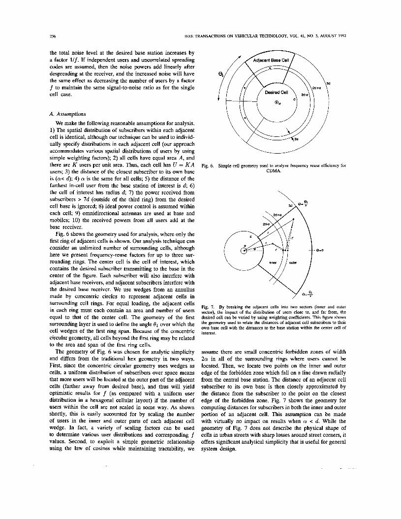
Fig. 6 shows the geometry used for analysis, where only the first ring of adjacent cells is shown. Our analysis technique can consider an unlimited number of surrounding cells, although here we present frequency-reuse factors for up to three sur- rounding rings. The center cell is the cell of interest, which contains the desired subscriber transmitting to the base in the center of the figure. Each subscriber will also interfere with adjacent base receivers, and adjacent subscribers interfere with the desired base receiver. We use wedges from an annullus made by concentric circles to represent adjacent cells in surrounding cell rings. For equal loading, the adjacent cells in each ring must each contain an area and number of users equal to that of the center cell. The geometry of the first surrounding layer is used to define the angle 81 over which the cell wedges of the first ring span. Because of the concentric circular geometry, all cells beyond the first ring may be related to the area and span of the first ring cells.
The geometry of Fig. 6 was chosen for analytic simplicity and differs from the traditional hex geometry in two ways. First, since the concentric circular geometry uses wedges as cells, a uniform distribution of subscribers over space means that more users will be located at the outer part of the adjacent cells (farther away from desired base), and thus will yield optimistic results for f (as compared with a uniform user distribution in a hexagonal cellular layout) if the number of users within the cell are not scaled in some way. As shown shortly, this is easily accounted for by scaling the number of users in the inner and outer parts of each adjacent cell wedge. In fact, a variety of scaling factors can be used to determine various user distributions and corresponding f values. Second, to exploit a simple geometric relationship using the law of cosines while maintaining tractability, we
Fig. 6. Simple cell geometry used to analyze frequency reuse efficiency for CDMA.
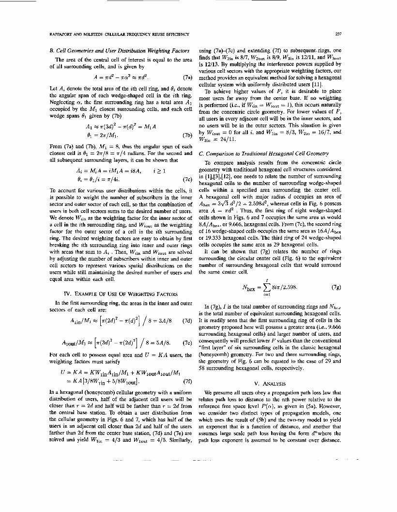
Fig. 7. By breaking the adjacent cells into two sectors (inner and outer sector), the impact of the distribution of users close to, and far from, the desired cell can be varied by using weighting coefficients. This figure shows the geometry used to relate the distances of adjacent cell subscribers to their own base cell with the distances to the base station within the center cell of interest.
assume there are small concentric forbidden zones of width 2a in all of the surrounding rings where users cannot be located. Then, we locate two points on the inner and outer edge of the forbidden zone which fall on a line drawn radially from the central base station. The distance of an adjacent cell subscriber to its own base is then closely approximated by the distance from the subscriber to the point on the closest edge of the forbidden zone. Fig. 7 shows the geometry for computing distances for subscribers in both the inner and outer portion of an adjacent cell. This assumption can be made with virtually no impact on results when a c d. While the geometry of Fig. 7 does not describe the physical shape of cells in urban streets with sharp losses around street comers, it offers significant analytical simplicity that is useful for general system design.
RAPPAPORT AND MILSTEIN: CELLULAR FREQUENCY REUSE EFFICIENCY 237
B. Cell Geometries and User Distribution Weighting Factors
of all surrounding cells, and is given by
using (7aH7c) and extending (70 to subsequent. rings, one finds that W2in is 8/7, Wzout is 8/9, W3in is 12/11, and W 3 ~ t is 12/13. By multiplying the interference powers supplied by various cell sectors with the appropriate weighting factors, our method provides an equivalent method for solving a hexagonal
The area of the central cell of interest is equal to the area
A = r d 2 - 7ra2 M rd2 . ( 7 4
Let Ai denote the total area of the ith cell ring, and Bi denote the angular span of each wedge-shaped cell in the ith ring. Neglecting a, the first surrounding ring has a total area A1 occupied by the M I closest surrounding cells, and each cell wedge spans 81 given by (7b)
A1 M ~ ( 3 d ) ~ - r (d)2 = MIA
el = 2 r / ~ 1 . (7b)
From (7a) and (7b), Ml = 8, thus the angular span of each closest cell is 81 = 2 r / 8 = r / 4 radians. For the second and all subsequent surrounding layers, it can be shown that
Ai = MiA = iM1A = i8A, i 2 1 ei = el/i = r / 4 i . (7c)
To account for various user distributions within the cells, it is possible to weight the number of subscribers in the inner sector and outer sector of each cell, so that the combination of users in both cell sectors sums to the desired number of users. We denote Wiin as the weighting factor for the inner sector of a cell in the ith surrounding ring, and Wiout as the weighting factor for the outer sector of a cell in the ith surrounding ring. The desired weighting factors are easy to obtain by first breaking the ith surrounding ring into inner and outer rings with areas that sum to Ai . Then, Wiin and Wiout are solved by adjusting the number of subscribers within inner and outer cell sectors to represent various spatial distributions on the users while still maintaining the desired number of users and equal area within each cell.
I v . EXAMPLE OF USE OF WEIGHTING FACTORS In the first surrounding ring, the areas in the inner and outer
sectors of each cell are:
Alout/M1 x [ ~ ( 3 d ) ~ - ~ ( 2 d ) ~ ] / 8 = 5A/8. (7e)
For each cell to possess equal area and U = K A users, the weighting factors must satisfy
U = K A = KWlinAiin/Ml+ KW1outAlout/M1
= K A [3/8W1in + 5/8Wlo,t]. (70
In a hexagonal (honeycomb) cellular geometry with a uniform distribution of users, half of the adjacent cell users will be closer than T = 2d and half will be farther than T = 2d from the central base station. To obtain a user distribution from the cellular geometry in Figs. 6 and 7, which has half of the users in an adjacent cell closer than 2d and half of the users farther than 2d from the center base station, (7d) and (7e) are solved and yield W1in = 413 and Wlout = 415. Similarly,
cellular system with uniformly distributed users [ll]. To achieve higher values of F, it is desirable to place
most users far away from the center base. If no weighting is performed (i.e., if Wiin = Wiout = l ) , this occurs naturally from the concentric circle geometry. For lower values of F, all users in every adjacent cell will be in the inner sectors, and no users will be in the outer sectors. This situation is given by Wiout = 0 for all i, and W1in = 8/3, W2in = 16/7, and W3in = 24/11.
C. Comparison to Traditional Hexagonal Cell Geometry To compare analysis results from the concentric circle
geometry with traditional hexagonal cell structures considered in [1],[3],[12], one needs to relate the number of surrounding hexagonal cells to the number of surrounding wedge-shaped cells within a specified area surrounding the center cell. A hexagonal cell with major radius d occupies an area of Ahex = 3fi d2/2 = 2.598d2, whereas cells in Fig. 6 possess area A = r d 2 . Thus, the first ring of eight wedge-shaped cells shown in Figs. 6 and 7 occupies the same area as would 8A/Ah,,, or 9.666, hexagonal cells. From (7c), the second ring of 16 wedge-shaped cells occupies the same area as 16A/Ah,, or 19.333 hexagonal cells. The third ring of 24 wedge-shaped cells occupies the same area as 29 hexagonal cells.
It can be shown that (7g) relates the number of rings surrounding the circular center cell (Fig. 6) to the equivalent number of surrounding hexagonal cells that would surround the same center cell.
1
i=l
In (7g), I is the total number of surrounding rings and NheZ is the total number of equivalent surrounding hexagonal cells. It is readily seen that the first surrounding ring of cells in the geometry proposed here will possess a greater area (i.e., 9.666 surrounding hexagonal cells) and larger number of users, and consequently will predict lower F values than the conventional “first layer” of six surrounding cells in the classic hexagonal (honeycomb) geometry, For two and three surrounding rings, the geometry of Fig. 6 can be equated to the case of 29 and 58 surrounding hexagonal cells, respectively.
V. ANALYSIS We presume all users obey a propagation path loss law that
relates path loss to distance to the nth power relative to the reference free space level P(a) , as given in (Sa). However, we consider two distinct types of propagation models, one which uses the result of (5b) and the two-ray model to yield an exponent that is a function of distance, and another that assumes large scale path loss having the form d”where the path loss exponent is assumed to be constant over distance.
238 IEEE TRANSACXIONS ON VEHICULAR TECHNOLOGY, VOL. 41, NO. 3, AUGUST 1992
All subscribers are assumed to be under power control within their own cells such that all desired mobile signals arrive with the same power P, as the closest user within their own cell. Thus, all subscriber transmitter powers are referenced to the power transmitted by the closest subscriber within the cell, which is denoted as Pa .
Under perfect power control within the center cell, the received power of each of the in-cell subscribers at the base receiver is P, , and the interfering power NO due to all but the single desired in-cell subscriber is given by
No = P,(U - 1) M P,U = P,KA ( 8 4
regardless of the path loss law within the cell (assuming there is sufficient dynamic range on the power transmitted by the subscriber). Without loss of generality in (Sa), we replace P, by Pa , the power received at the base due to the closest subscribers. Since we assume the same close-in propagation occurs within a m of every base station in the system, all signal levels may be referenced to the received power at a radial distance a pfrom any base station. Then, for the center cell of interest,
No = PaKA. (8b)
For simplicity, Pa may be assumed to be unity so that NO is equal to the number of users in each cell. Furthermore, K can be arbitrarily set to 1/A, so that the noise due to in-cell users is unity, regardless of the number of users, and all subsequent cells add to the unit noise level produced by the center cell of interest. Each subscriber in the center cell has a transmitted power equal to Pa(r/a)", where r is the distance from mobile to base, and n is the propagation path loss exponent in (5). Note that n may be a function of r and a, as in (Sb) and Figs. 2 4 , or n may be assumed constant over distance, as shown in Fig. 5 and Table I.
The adjacent cell subscribers are under power control within their own cell and are a distance r' from their own base station. As shown in Fig. 7 for the first ring (i=l), the relationship between r' and r is given by (9) using the law of cosines. The true transmitter power for each subscriber in the adjacent cell can be related by Pa and r', where r' is related to r and 0 by
112 r2 sin20 + (2 * d * i - cy - r * cos0 )2 ) ,
for d * i 5 r 5 2 * d * a - Q
r' = r2sin20 + ( r * cos0 - 2 * d * i - a)' ( for 2 * d * i + a 5 r 5 d(2 * i + 1).
(9)
Let Pai(r, 0, a ) denote the power received at the center base station from a subscriber at a particular location in an adjacent ith layer cell. Then, the received power from each adjacent cell user is given by
P&(T, 0, a ) = Pa(.'/""('''")(Q/.)n(r,a) (10)
where r' is a function of 0 as given by (9). The total interference power, N,;, contributed by all subscribers in a
cell in the ith surrounding ring is found by summing up the received powers from each user in the adjacent cell
~m = Paz(r,e,a). ( W u e A , / M ,
It is clear from (10) that Pa, values in ( l la ) are functions of the specific locations of adjacent cell users as given by (9) and (lo), and that the summation in ( l l a ) represents a summation over a geographic cell region. To compute (lla), one can use any spatial distribution of users and any distance-dependent path loss. In real-world situations, individual values of Pa, will exhibit shadow fading (e.g. log-normal fading) and this can be modeled statistically in ( l la ) in a Monte Carlo fashion. In our work, though, we have assumed symmetric shadow fading of Pa, at specific T-R separations about the distance-dependent mean.
Equation ( l la ) is sufficiently general to solve for the power contributed from adjacent cells obeying any distance- dependent propagation path loss law. One simple way of manipulating a specified distribution of users is to employ weighting factors described in Section 111-B. With weighting factors, the total noise powers contributed by users within the inner and outer sectors of adjacent cells can be easily scaled without the need to recompute the interference powers contributed by individual users. Thus, bounds on average adjacent cell noise can be obtained easily. To use the weighting factors, ( l l a ) can be written as two separate summations as given in (llb):
~ a z = Wlin paz(r10, a ) ueA,,,l&f,
+Wl,ut Paz(r,O,a). (1lb) ueA,,,t/M,
Note that if WlIn and Wlout are unity, then ( l lb ) is identical to (lla). As discussed in Section 111-B, if WlIn = 4/3 and Wlout = 4/5, then a uniform spatial distribution of users in ( l la ) can be used in ( l lb ) to provide the same N,, as a hexagonal cellular system.
A. Results
Equation ( l lb ) was solved numerically using a uniform spatial distribution of users for specific values of close-in reference distance and cell radius d. Then, the frequency reuse factor was computed from (6), where three different user distribution weightings in ( l lb ) gave rise to various values for f using identical channels.
All results in this work were found using 20 000 uniformly spaced users in each adjacent cell for d = 2 km, and 400 000 equally spaced users within d = 10 km cells. Equation (6a) and symmetry were exploited to limit computations to a single cell within each ring.
Tables I1 and 111 give values of frequency reuse factor ( f ) as a function of path loss exponent (assumed constant over distance) for a = 0.1 km and a = 0.05 km, respectively, for the cases of cell boundaries at d = 2 km and d = 10 km. Only one ring of adjacent cells was considered for results given in the tables. Note that f values for n = 4 are comparable to those
RAPPAPORT AND MILSTEIN: CELLULAR FREQUENCY REUSE EFFICIENCY
0.70
0.65
0.60
0.55
0.50
0.45 L
0.40
0 3 5
0.30
0.25
020
239
-
-
-
-
-
-
-
-
-
-
-
TABLE I1 FREQUENCY REUSE FACTOR FOR CDMA SYSTEMS AS A FUNCTION
OF PROPAGATION EXPONENT. ONE RING OF ADJACENT CELLS CONSIDERED FOR D = 2 h AND D = 10 km, cy = 0.1 km
Frequency Reuse Factor Lower Bound Hex Case Upper Bound
d(km) W1 ~ 3 . 0 WI = 1.38 W1 = 1.0
Wz = 0.0 W2 = 0.78 W2 = 1.0
2.0 2 0.326 0.434 0.471 2.0 3 0.423 0.571 0.625 2.0 4 0.499 0.666 0.721 10.0 2 0.310 0.422 0.457 10.0 3 0.399 0.553 0.606 10.0 4 0.466 0.638 0.698
TABLE 111 FREQUENCY REUSE FAWR FOR CDh4A SYSTEMS AS A FUNCTION OF
PROPAGATION EXPONENT; ONE RING OF ADJACENT CELLS CONSIDERED FOR D = 2 km AND D = 10 km, cy = 0.05 km
Freauencv Reuse Factor
2.0 2 0.316 0.425 0.462 2.0 3 0.408 0.558 0.613 2.0 4 0.479 0.646 0.707 10.0 2 0.308 0.419 0.455 10.0 3 0.396 0.550 0.603 10.0 4 0.462 0.634 0.695
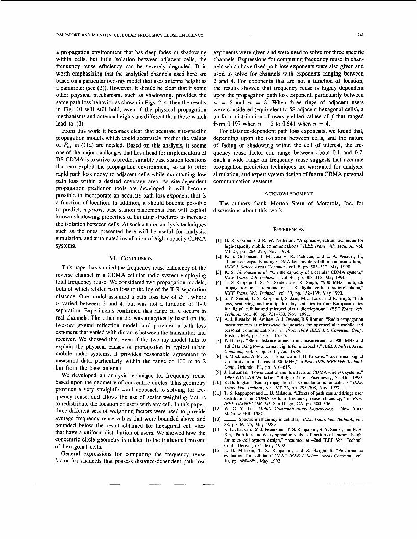
given in [1],[3], where a hexagonal cellular system geometry with a comparable number of adjacent users was considered. For weighting factors that offer uniform user distributions comparable to the hexagonal geometry, we see for d = 10 km, f is 64% for n = 4, 55% for n = 3, and 42% for n = 2. A loose upper bound and tight lower bound on f are also given in Tables I1 and 111. Weighting coefficients listed in Tables I1 and I11 differ slightly from those given in Section 111-B since the term mx2 was considered in calculations which led to tabular entries, but was neglected for the general results given in (7). For a propagation model that has a constant n over distance, it is evident that f is not sensitive to Q or d, but is highly sensitive to the value of the path loss exponent. Note that in free space channels (n = 2) with only one surrounding ring of adjacent cells, f is more than 3 dB down from the n = 4 result.
Although not shown in the tables, it is worth noting that when the first surrounding ring and just the inner portion of the second surrounding ring were considered in our analysis, we found f = 0.606 for the d uniform (hexagonal) user distribution case, which is comparable to results obtained in [3] using 18 surrounding hex cells. Using (7g) it can be shown that 18 hexagonal cells occupy the same area as the first ring
'. 0 . 1 5 ' ' ' ' ' ' ' ' '
0 1 2 3 4 Numberof Rings
Fig. 8. exponent, n, and the number of rings surrounding the cell of interest.
Plot of the frequency reuse factor, f, as a function of the path loss
and the inner portion of the second ring. Thus, our analysis yields identical results to average results in [3] which uses hexagonally shaped cells.
Fig. 8 extends the results shown in Tables I1 and 111 to include the interference effects of the second and third rings. One can see how additional rings effect the frequency reuse efficiency of CDMA. Fig. 8 shows f as a function of the number of adjacent cell rings for the case where path loss exponents remain constant with distance, with n values ranging from 2 to 4. The three weightings given in Section IV (hex, upper bound, lower bound) were used to give representative ranges on f . For the data shown in Fig. 8, = 0.1 km and d = 10 km were assumed. Fig. 8 shows thatf drops to below 0.2 when n = 2 and three surrounding rings are considered. However, for n = 4, the hexagonal case (uniform distribution) has a frequency reuse efficiency of 54% with three layers. Note that for three surrounding rings, the n = 3 channel affords 3 dB more reuse than does the n = 2 channel, and the n = 2 reuse degrades by 3 dB when the surrounding layers are increased from one to three. These data indicate how the propagation environment can impact the estimate of frequency reuse.
In wireless channels, deep fading between an adjacent base and one of its subscribers will dramatically impact that subscriber's power control, and thus the power received from that unit at the cell of interest [15]. This is seen from (lo), since if an adjacent user is in a deep fade while transmitting to its own base, the required transmitter power will be large and could strongly interfere with the base of interest.
We consider three different two-ray propagation channels that have a distance dependent path loss exponent. These channels were derived using (1)-(3), and possess the path loss
0.70
0.65
0.60
L 0.55
0.50
0.45
8, d=l Okm and hr=2m
ht=88m,lc=942MHz
-
-
-
-
-
-
0 1 2 3 4 Number of Rings
Fig. 9. Plot of the frequency reuse factor, f, as a function of three different propagation channels, for d = 10 km and (Y = 100 m. The propagation channels were developed from a two-ray ground reflection model. Path loss exponent values for the three channels, as a function of distance, are shown in Figs. 2-4.
IEEE TRANSACTIONS ON VEHICULAR TECHNOLOGY, VOL. 41, NO. 3, AUGUST 1992
responses given in Figs. 2-4. We assume that all base stations in the cellular system have identical channel (i.e., path loss) characteristics over distance. Further, to reduce the impact that deep fades have on results, we assume that within a 2 km radius of each base station, each base station's subscribers can have path loss fades no more than 40 dB below the reference power P(cr). This fade limit ensures our analysis yields realistic results, since subscribers in an actual system cannot transmit excessive power levels to overcome path loss.
Figs. 9 and 10 show how cell size and a distance-dependent propagation path loss exponent can impact frequency reuse. Fig. 9 shows values o f f for the case of large cells (d = 10 km, (Y = 100 m). It is clear from Figs. 2-4 that when d = 10 km, all adjacent cells are located in the asymptotic region of d4 path loss from the cell of interest. Fig. 9 indicates f ranges between 0.4 and 0.7, regardless of the particular two-ray channel or user distribution. By comparing Fig. 8 results with those in Fig. 9, one can see that for all user distributions, the three different distance-dependent analytical channels yield frequency reuse factors close to those offered by channels using a d4 path loss law. This is due to the fact that the cell size is large, and natural isolation of adjacent noise power due to path loss occurs. The frequency reuse factors obtained for each of the three two-ray channels are, at most, only 5% lower than results obtained for the d4 propagation law.
Fig. 10 shows how the same three two-ray propagation channels used to produce results in Fig. 9 can dramatically alter the frequency reuse when small cells are considered. For d = 2 km and a=lOO m, path loss values shown in Figs.
0.8
0.7
0.6
0.5
+ 0.4
0.3
0 2
0.1
d=2km and hr=2m
upper . . # , . , . . - - lower ht=88m,lc=942MHZ ht=40m.l~=942MH2
a,.,
-. .A
Fig. 10. Plot of the frequency reuse factor, f, as a function of three different propagation channels, for d = 2km and a= 100 m. The propagation channels were developed from a two-ray ground reflection model. Path loss exponent values for the three channels, as a function of distance, are shown in Figs. 2-4.
2-4 were used to determine values of f . For 2 km cells, it is clear that the two-ray channels described by Figs. 2 and 3 have adjacent subscribers that provide stronger signal levels than those predicted by a d4 path loss law. In addition, the proportion of deep faded regions within the adjacent 2 km cells is much greater than in 10 km cells. This means that a greater percentage of adjacent users in the smaller cells will need to provide greater transmitter power to overcome their own in-cell fades. While the channel represented in Fig. 4 offers frequency-reuse values virtually unchanged from those found for the same channel in a 10 km cellular system, it is readily seen that the channels portrayed by Figures 2 and 3 substantially degrade f for a 2 km system.
Fig. 10 shows the impact that close-in propagation has on frequency reuse. As seen in Fig. 2, there are many deep nulls within a 2 km radius from the base, and the first ring of subscribers will offer signal levels only 21 to 35 dB down from P(a) . Fig. 10 shows how both of these factors lead to values of f (with three rings and uniform distribution of users in each cell) near 0.1 for the channel portrayed in Fig. 2. This is more than six times (8 dB) lower than the frequency reuse obtained using the exact same channel except with d = 10 km. Also, the channel portrayed in Fig. 2 provides f values that are 8 dB lower than results obtained for d = 2 km using the channel portrayed in Fig. 4. Fig. 10 shows the channel portrayed by Fig. 3 does not degrade f as severely, but the resulting frequency reuse factor (with three rings and uniform distribution of users in each cell) of 0.47 is 0.6 dB less than that provided by the same channel in a 10 km cell system. These results explicitly show that if CDMA is implemented in
RAPPAPORT AND MILSTEIN: CELLULAR FREQUENCY REUSE EFFICIENCY 241
a propagation environment that has deep fades or shadowing within cells, but little isolation between adjacent cells, the frequency reuse efficiency can be severely degraded. It is worth emphasizing that the analytical channels used here are based on a particular two-ray model that uses antenna height as a parameter (see (3)). However, it should be clear that if some other physical mechanism, such as shadowing, provides the same path loss behavior as shown in Figs. 2-4, then the results in Fig. 10 will still hold, even if the physical propagation mechanisms and antenna heights are different than those which lead to (3).
From this work it becomes clear that accurate site-specific propagation models which could accurately predict the values of P,i in ( l l a ) are needed. Based on this analysis, it seems one of the major challenges that lies ahead for implementors of DS-CDMA is to strive to predict suitable base station locations that can exploit the propagation environment, so as to offer rapid path loss decay to adjacent cells while maintaining low path loss within a desired coverage area. As site-dependent propagation prediction tools are developed, it will become possible to incorporate an accurate path loss exponent that is a function of location. In addition, it should become possible to predict, a priori, base station placements that will exploit known shadowing properties of building structures to increase the isolation between cells. At such a time, analysis techniques such as the ones presented here will be useful for analysis, simulation, and automated installation of high-capacity CDMA systems.
VI. CONCLUSION
This paper has studied the frequency reuse efficiency of the reverse channel in a CDMA cellular radio system employing total frequency reuse. We considered two propagation models, both of which related path loss to the log of the T-R separation distance. One model assumed a path loss law of d” , where n varied between 2 and 4, but was not a function of T-R separation. Experiments confirmed this range of n occurs in real channels. The other model was analytically based on the two-ray ground reflection model, and provided a path loss exponent that varied with distance between the transmitter and receiver. We showed that, even if the two ray model fails to explain the physical causes of propagation in typical urban mobile radio systems, it provides reasonable agreement to measured data, particularly within the range of 100 m to 2 km from the base antenna.
We developed an analysis technique for frequency reuse based upon the geometry of concentric circles. This geometry provides a very straightforward approach to solving for fre- quency reuse, and allows the use of scaler weighting factors to redistribute the location of users with any cell. In this paper, three different sets of weighting factors were used to provide average frequency reuse values that were bounded above and bounded below the result obtained for hexagonal cell sites that have a uniform distribution of users. We showed how the concentric circle geometry is related to the traditional mosaic of hexagonal cells.
General expressions for computing the frequency reuse factor for channels that possess distance-dependent path loss
exponents were given and were used to solve for three specific channels. Expressions for computing frequency reuse in chan- nels which have fixed path loss exponents were also given and used to solve for channels with exponents ranging between 2 and 4. For exponents that are not a function of location, the results showed that frequency reuse is highly dependent upon the propagation path loss exponent, particularly between n = 2 and n = 3. When three rings of adjacent users were considered (equivalent to 58 adjacent hexagonal cells), a uniform distribution of users yielded values of f that ranged from 0.197 when n = 2 to 0.541 when n = 4.
For distance-dependent path loss exponents, we found that, depending upon the isolation between cells, and the nature of fading or shadowing within the cell of interest, the fre- quency reuse factor can range between about 0.1 and 0.7. Such a wide range on frequency reuse suggests that accurate propagation prediction techniques are warranted for analysis, simulation, and expert system design of future CDMA personal communication systems.
ACKNOWLEDGMENT
The authors thank Morton Stern of Motorola, Inc. for discussions about this work.
REFERENCES
G. R. Cooper and R. W. Nettleton, “A spread-spectrum technique for high-capacity mobile communications,” IEEE Trans. Veh. Technol., vol.
K. S. Gilhousen, I. M. Jacobs, R. Padovan, and L. A. Weaver, Jr., “Increased capacity using CDMA for mobile satellite communication,” IEEE J. Select. Areas Commun., vol. 8, pp. 503-512, May 1990. K. S. Gilhousen et al. “On the capacity of a cellular CDMA system,” IEEE Trans. Veh. Technol., , vol. 40, pp. 303-312, May 1990. T. S Rappaport, S. Y. Seidel, and R. Singh, “900 MHz multipath propagation measurements for U. S. digital cellular radiotelephone,” IEEE Trans. Veh. Technol., vol. 39, pp. 132-139, May 1990. S. Y. Seidel, T. S. Rappaport, S. Jain, M.L. Lord, and R. Singh, “Path loss, scattering, and multipath delay statistics in four European cities for digital cellular and microcellular radiotelephone,” IEEE Trans. Veh. Technol., vol. 40, pp. 721-730, Nov. 1991. A. J. Rustako, N. Amitay, G. J. Owens, R.S Roman, “Radio propagation measurements at microwave frequencies for microcellular mobile and personal communications,” in Proc. 1989 IEEE In?. Commun. Con$, Boston, MA, pp. 15.5.1-15.5.5. P. Harley, “Short distance attenuation measurements at 900 MHz and 1.8 GHz using low antenna heights for microcells,” IEEE J. Select. Areas Commun., vol. 7, pp. 5-11, Jan. 1989. S. Mockford, A. M. D. Turkmani, and J. D. Parsons, “Local mean signal variability in rural areas at 900 MHz,” in Proc. 1990 IEEE Veh. Technol. Conj, Orlando, FL, pp. 610-615. J. Holtzman, “Power control and its effects on CDMA wireless systems,” 1990 WINLAB Workshop,” Rutgers Univ., Piscataway, NJ, Oct. 1990. K. Bullington, “Radio propagation for vehicular communications,” IEEE Trans. Veh. Technol., vol. VT-26, pp. 295-308, Nov. 1977. T. S. Rappaport and L. B. Milstein, “Effects of path loss and fringe user distribution on CDMA cellular frequency reuse efficiency,” in Proc. IEEE GLOBECOM ‘90, San Diego, CA, pp. 500-506. W. C. Y. Lee, Mobile Communications Engineering New York: McGraw-Hill, 1982. spectrum efficiency in cellular,” IEEE Trans. Veh. Technol., vol. 38, pp. 69-75, May 1989. K. L. Blackard, M-J. Feuerstein, T. S. Rappaport, S. Y. Seidel, and H. H. Xia, “Path loss and delay spread models as functions of antenna height for microcell system design,” presented at 42nd IEEE Veh. Technol. Conf., Denver, CO, May 1992. L. B. Milstein, T. S. Rappaport, and R. Barghouti, “Performance evaluation for cellular CDMA,” IEEE J. Select. Areas Commun., vol. 10, pp. 680-689, May 1992.
VT-27, pp. 264-275, NOV. 1978.
242 IEEE TRANSACTIONS ON VEHICULAR TECHNOLOGY, VOL. 41, NO. 3, AUGUST 1992
Theodore S. Rappaport (S’83-M’84-S’85-M’87 -SM’91) was born in Brooklyn, NY, on Novem- ber 26, 1960. He received the B.S.E.E., M.S.E.E., and Ph.D. degrees from Purdue University, West Lafayette, IN, in 1982, 1984, and 1987, respec- tively.
In 1988 he joined the electrical engineering fac- ulty of Virginia Polytechnic Institute and State Uni- versity, Blacksburg, where is he is an Associate Professor and Director of the Mobile and Portable Radio Research Group. He conducts research in
mobile radio communication system design, simulation, and RF propagation through measurements and modeling. He has authored or coauthored technical papers in the areas of mobile radio communications and propagation, vehicular navigation, ionospheric propagation, and wide-band communications.
Dr. Rappaport holds a U.S. patent for a wide-band antenna, and is co- inventor of SIRCIM, an indoor radio channel simulator that has been adopted by more than 50 companies and universities. In 1990 he received the Marconi Young Scientist Award for his contributions in indoor radio communications and was named an NSF Presidential Faculty Fellow in 1992. He is an active member of the IEEE Communications and Vehicular Technology Societies and serves as a Senior Editor of the IEEE JOURNAL ON SELECTED AREAS IN COMMUNICA?TONS. He is a Registered Professional Engineer in the State of Virginia, and is a Fellow of the Radio Club of America. He is also President of TSR Technologies, a cellular radio and paging test equipment manufacturer.
Laurence B. Milstein (S’66-M’68-SM’77-F’85) received the B.E.E. degree from the City College of New York, New York, NY, in 1964, and the M.S. and Ph.D. degrees in electrical engineering from the Polytechnic Institute of Brooklyn, Brooklyn, NY, in 1966 and 1968, respectively.
From 1968 to 1974 he was employed by the Space and Communications Group of Hughes Aircraft Company, and from 1974 to 1976 he was a member of the Department of Electrical and Systems Engi- neering, Rensselaer Polytechnic Institute, Troy, NY.
Since 1976 he has been with the Department of Electrical and Computer En- gineering, University of San Diego, La Jolla, CA, where he is a Professor and former Department Chairman, working in the area of digital communication theory with special emphasis on spread-spectrum communications systems. He has also been a consultant to both government and industry in the areas of radar and communication.
Dr. Milstein was an Associate Editor for Communication Theory for the IEEE TRANSACTIONS ON COMMMUNICATIONS, an Associate Editor for Book Reviews for the IEEE TRANSACTIONS ON INFORMATION THEORY, and an Associate Technical Editor for the IEEE Communications Magazine. He has been on the Board of Governors of the IEEE Communications Society, and was the Vice President of Technical Affairs in 1990 and 1991. He is currently a member of the Board of Governors of the IEEE Information Theory Society, and is a member of Eta Kappa Nu and Tau Beta Pi.
Related Documents