Effects of geometrical and mechanical properties of fiber and matrix on composite fracture toughness Yuli Chen a,⇑ , Shengtao Wang a , Bin Liu b , Jianyu Zhang a,⇑ a Institute of Solid Mechanics, Beihang University, Beijing 100191, PR China b AML, Department of Engineering Mechanics, Tsinghua University, Beijing 100084, China article info Article history: Available online 13 December 2014 Keywords: Nano-composites Ultrathin fibers Nanotubes Fracture toughness Fiber bridging abstract Composites reinforced by thinner fibers are intensively studied in recent years and expected to have bet- ter mechanical properties. With development of nanotechnology, the diameter of fiber can be as thin as several nanometers, such as nanofibers and nanotubes. Then, do these thinner fibers definitely result in composites with better mechanical properties? In this paper, the toughening effect of reinforcing fibers in composites is investigated based on the three-level failure analysis model. It is found that thinner reinforcing fibers do not definitely confer better fracture toughness on composites. The optimal fiber diameter is that making the failure mode just in the transition from fiber pull-out to fiber break, which is about 2–6 nm for carbon nanotubes and around 100 nm for carbon nanofibers. In addition, the effects of fiber, matrix and interface properties are all investigated, and their analytical optimal values are obtained and summarized in a table, which provides important reference for advanced composites design. Ó 2014 Elsevier Ltd. All rights reserved. 1. Introduction Fiber reinforced composites have been widely used in various fields, especially in aerospace, military and automotive industries. With the development of nanomaterials, the fiber-type reinforce- ments with diameters as thin as several nanometers, such as nano- tubes (NTs) and nanofibers (NFs), are increasingly used in advanced composites for better mechanical, electrical, optical and chemical properties [1–5]. As thin, strong and multifunctional reinforcements, NFs/NTs have drawn extensive attentions of researches. Taking carbon nanotubes (CNTs) [6–11] for example, their Young’s modulus and strength are up to 1 TPa and 100 GPa, respectively [9–11], and their diameter typically ranges from 0.8 nm to 2 nm for single-wall CNTs (SWCNTs) and from 5 nm to 20 nm for multi-wall CNTs (MWCNTs) [9]. Tremendous efforts have been done to investigate the mechan- ical [12–23], electrical [12–15,24] and thermal [15,25–27] proper- ties of CNT-reinforced composites. Thereinto, a large part of the works focuses on the toughening effect of CNT-reinforced compos- ites. Experiments have shown large scatting and even opposite results in the improvement in fracture toughness by the CNTs, ranging from 10% to 4080% [16–23]. The large scatting of exper- imental data is mainly attributed to CNT/matrix interface [23] as well as the content and dispersion of CNTs [19,23]. In order to make deeper investigations for a better view to the toughness of CNT reinforced composites, theoretical and simulation studies have also been carried out [28–40]. Chen et al. [30] studied the toughness of composites reinforced by curved CNTs with a statistical distribution of strength, and suggested that increasing CNT curvature could reduce toughness of nano-composites depending on chosen parameters such as interfacial friction prop- erties, and nanotube and matrix modulus. Pavia and Curtin [31] investigated the effect of wave, finite-length nanofibers on the ten- sile strength and fracture work of ceramic matrix. They have con- sidered many factors to make their model close to the real problem, including interfacial friction and sliding [32–34], strength distribution, and curvature and length of nanofibers. They revealed an optimal region of morphology that maximizes composite strength and toughness. Chen et al. [35,36] developed a three-level failure analysis model to investigate the interfacial effect on the fracture toughness enhancement of CNTs. They found that neither longer reinforced CNTs nor stronger CNT/matrix interfaces can definitely lead to better fracture toughness of these composites. Furthermore, the optimal interfacial strength and the optimal CNT length are those making the failure mode just in the transition from CNT pull-out to CNT break. http://dx.doi.org/10.1016/j.compstruct.2014.12.011 0263-8223/Ó 2014 Elsevier Ltd. All rights reserved. ⇑ Corresponding authors. Tel.: +86 (0) 10 8231 8410; fax: +86 (0) 10 8233 9228 (Y. Chen). Tel.: +86 (0) 10 8233 8663; fax: +86 (0) 10 8233 9228 (J. Zhang). E-mail addresses: [email protected] (Y. Chen), [email protected] (J. Zhang). Composite Structures 122 (2015) 496–506 Contents lists available at ScienceDirect Composite Structures journal homepage: www.elsevier.com/locate/compstruct

Welcome message from author
This document is posted to help you gain knowledge. Please leave a comment to let me know what you think about it! Share it to your friends and learn new things together.
Transcript

Composite Structures 122 (2015) 496–506
Contents lists available at ScienceDirect
Composite Structures
journal homepage: www.elsevier .com/locate /compstruct
Effects of geometrical and mechanical properties of fiber and matrixon composite fracture toughness
http://dx.doi.org/10.1016/j.compstruct.2014.12.0110263-8223/� 2014 Elsevier Ltd. All rights reserved.
⇑ Corresponding authors. Tel.: +86 (0) 10 8231 8410; fax: +86 (0) 10 8233 9228(Y. Chen). Tel.: +86 (0) 10 8233 8663; fax: +86 (0) 10 8233 9228 (J. Zhang).
E-mail addresses: [email protected] (Y. Chen), [email protected](J. Zhang).
Yuli Chen a,⇑, Shengtao Wang a, Bin Liu b, Jianyu Zhang a,⇑a Institute of Solid Mechanics, Beihang University, Beijing 100191, PR Chinab AML, Department of Engineering Mechanics, Tsinghua University, Beijing 100084, China
a r t i c l e i n f o
Article history:Available online 13 December 2014
Keywords:Nano-compositesUltrathin fibersNanotubesFracture toughnessFiber bridging
a b s t r a c t
Composites reinforced by thinner fibers are intensively studied in recent years and expected to have bet-ter mechanical properties. With development of nanotechnology, the diameter of fiber can be as thin asseveral nanometers, such as nanofibers and nanotubes. Then, do these thinner fibers definitely result incomposites with better mechanical properties? In this paper, the toughening effect of reinforcing fibers incomposites is investigated based on the three-level failure analysis model. It is found that thinnerreinforcing fibers do not definitely confer better fracture toughness on composites. The optimal fiberdiameter is that making the failure mode just in the transition from fiber pull-out to fiber break, whichis about 2–6 nm for carbon nanotubes and around 100 nm for carbon nanofibers. In addition, the effectsof fiber, matrix and interface properties are all investigated, and their analytical optimal values are obtainedand summarized in a table, which provides important reference for advanced composites design.
� 2014 Elsevier Ltd. All rights reserved.
1. Introduction
Fiber reinforced composites have been widely used in variousfields, especially in aerospace, military and automotive industries.With the development of nanomaterials, the fiber-type reinforce-ments with diameters as thin as several nanometers, such as nano-tubes (NTs) and nanofibers (NFs), are increasingly used in advancedcomposites for better mechanical, electrical, optical and chemicalproperties [1–5].
As thin, strong and multifunctional reinforcements, NFs/NTshave drawn extensive attentions of researches. Taking carbonnanotubes (CNTs) [6–11] for example, their Young’s modulus andstrength are up to 1 TPa and 100 GPa, respectively [9–11], and theirdiameter typically ranges from 0.8 nm to 2 nm for single-wall CNTs(SWCNTs) and from 5 nm to 20 nm for multi-wall CNTs (MWCNTs)[9]. Tremendous efforts have been done to investigate the mechan-ical [12–23], electrical [12–15,24] and thermal [15,25–27] proper-ties of CNT-reinforced composites. Thereinto, a large part of theworks focuses on the toughening effect of CNT-reinforced compos-ites. Experiments have shown large scatting and even oppositeresults in the improvement in fracture toughness by the CNTs,
ranging from �10% to 4080% [16–23]. The large scatting of exper-imental data is mainly attributed to CNT/matrix interface [23] aswell as the content and dispersion of CNTs [19,23]. In order tomake deeper investigations for a better view to the toughness ofCNT reinforced composites, theoretical and simulation studieshave also been carried out [28–40]. Chen et al. [30] studied thetoughness of composites reinforced by curved CNTs with astatistical distribution of strength, and suggested that increasingCNT curvature could reduce toughness of nano-compositesdepending on chosen parameters such as interfacial friction prop-erties, and nanotube and matrix modulus. Pavia and Curtin [31]investigated the effect of wave, finite-length nanofibers on the ten-sile strength and fracture work of ceramic matrix. They have con-sidered many factors to make their model close to the realproblem, including interfacial friction and sliding [32–34], strengthdistribution, and curvature and length of nanofibers. They revealedan optimal region of morphology that maximizes compositestrength and toughness. Chen et al. [35,36] developed a three-levelfailure analysis model to investigate the interfacial effect on thefracture toughness enhancement of CNTs. They found that neitherlonger reinforced CNTs nor stronger CNT/matrix interfaces candefinitely lead to better fracture toughness of these composites.Furthermore, the optimal interfacial strength and the optimalCNT length are those making the failure mode just in the transitionfrom CNT pull-out to CNT break.

Y. Chen et al. / Composite Structures 122 (2015) 496–506 497
However, an important question arises: do thinner fibers defi-nitely result in composites with better mechanical properties?Usually, thinner fibers are supposed to confer better mechanicalproperties on composites due to their higher specific interfacialarea and larger aspect ratio [4,5,41–45]. But when the researchscope extends to nano-composites and the concept of fiber extendsto nanofibers and nanotubes, the effect of fiber diameter on themechanical properties of composites remains unrevealed. Besides,another similar question is: do stiffer fibers definitely result incomposites with better mechanical properties? It is of greatimportance to reveal the effect of fiber stiffness on the mechanicalproperties of composites. This paper aims to provide answers tothese questions by investigating the effects of fiber diameter andfiber stiffness as well as other fiber, matrix and interface propertieson the composite fracture toughness.
2. Fracture toughness enhancement
As reviewed above, there are already a large amount of theoret-ical models for the fracture toughness of NFs/NTs reinforcedcomposites [28–40]. However, a simple analytical solution isdesired by material researchers for convenient applications inpractical composites. Chen et al.’s study [35] provides a simpleanalytical expression for the fracture toughness enhanced bybridging CNTs in composites. Their theoretical outcomes agreewell with atomic simulations [35] and the degraded result of Paviaand Curtin’s model [32], and have been validated by experiments[37,38]. So Chen et al.’s model is adopted in this paper.
Following Chen et al.’s three-level failure analysis model [35], incomposites with macroscopic cracks, high strength reinforcingfibers can retard crack propagation, and a fracture zone bridgedby fibers is formed at the crack tip, as shown in Fig. 1(a). Thistoughening effect of bridging fibers is equivalent to that of nonlin-ear springs connecting the upper and lower crack surfaces, asshown in Fig. 1(b). In this level, the fracture toughness enhance-ment of the bridging fibers can be obtained by fracture mechanicsprovided that the force-displacement relation for these springs isknown. In order to attain the constitutive relation of the springs,the pulling force F and pull-out displacement d of a single fiberare studied, as shown in Fig. 1(c). In this level, it is well acknowl-edged that the two typical failure modes are interfacial debondingand fiber break, and the F–d curve can be solved by mesomechanicsanalysis [46–51]. The F–d curve and failure mode depend on theinterfacial interactions, such as atomic bond properties for NF/NTreinforced composites and cohesive forces for fiber–matrix mate-rial systems, as shown in Fig. 1(d). Therefore, the fiber reinforcedcomposites have three failure mode levels: a bond break at theatomistic level, fiber failure mode at the mesoscopic level and
K ∞
(b) Macroscopic le
⇔
(a)
K ∞
Fig. 1. Hierarchical failure analysis models: (a) fracture zone bridged with fibers at the crmesoscopic-level model to obtain the force-displacement relation of equivalent nonlineabond breaking.
macroscopic crack propagation at the macroscopic level. It shouldbe noted that the fibers in Fig. 1 are all well oriented becauseexperimental observations on the crack tip of CNT reinforced com-posite shows that most bridging CNTs are perpendicular to crackface due to the pulling stress [52] although they are actually dis-tributed randomly in the matrix. So the model in Fig. 1 can beextended for composites with randomly distributed fibers as well.In this paper, we will focus on the oriented fibers in order toestablish simple and practical analytical formulae for the effectsof fiber and matrix properties.
In atomistic level, a bond break occurs when the relative dis-placement between the fiber and the matrix Du reaches the criticalshear displacement db, which depends only on the type of function-alization bond at the interface, and the corresponding interfacestrength sb also depends on the interface bond density. Theinterface shear stress s is assumed to be proportional to therelative displacement Du, i.e.,
sðxÞ ¼ kDuðxÞ ¼ k½umðxÞ � uf ðxÞ� ð1Þ
where k = sb/db is the shear stiffness of the interface, um(x) and uf(x)are the axial displacements of the matrix and the fiber respectively,and x is the coordinate along the axial direction.
Supposing the fiber and the matrix are both linear elastic, withthe balance conditions of the fiber and the matrix, the shear stressdistribution can be derived as [35,48]
sðxÞ¼ Fpd2
f
4
ffiffiffiffiffiffiffiffiffiffiffiffiffiffiffiffiffiffiffiffiffiffiffiffiffiffiffiffiffiffiffiffiffiffiffiffisb
4Ef db
df1þ Ef cf
Em ð1�cf Þ
� �vuut
�
Ef cf
Em ð1�cf Þcosh x
ffiffiffiffiffiffiffiffiffiffiffiffiffiffiffiffiffiffiffiffiffiffiffiffiffiffiffiffiffiffiffiffiffiffiffiffiffiffi4sb
Ef db df1þ Ef cf
Em ð1�cf Þ
� �r� �þcosh ðx�LÞ
ffiffiffiffiffiffiffiffiffiffiffiffiffiffiffiffiffiffiffiffiffiffiffiffiffiffiffiffiffiffiffiffiffiffiffiffiffiffi4sb
Ef df db1þ Ef cf
Em ð1�cf Þ
� �r� �
sinh Lffiffiffiffiffiffiffiffiffiffiffiffiffiffiffiffiffiffiffiffiffiffiffiffiffiffiffiffiffiffiffiffiffiffiffiffiffiffi
4sbEf db df
1þ Ef cf
Emð1�cf Þ
� �r� � ð2Þ
where Ef and Em are the Young’s modulus of the fiber and the matrixrespectively, cf is the area fraction of fibers on the crack face andrepresents fiber volume fraction in composites, F is the pullingforce, L is the embedded length and df is the fiber diameter.
The distribution of the axial normal stress in the fiber can alsobe derived as
rðxÞ ¼ 4
pd2f
F �Z x
0pdf sðxÞdx
� �ð3Þ
The two main fiber-level failure modes are usually interfacial deb-onding and fiber break. Fiber break occurs when the maximum axialnormal stress reaches fiber strength rb
f . When the maximum shearstress reaches the interface strength sb, the interfacial chemicalbonds break, and the fiber is pulled out. Thus, the debonding/breaking critical condition can be established.
F
(c) Mesoscopic level
F
δvel (d) Atomistic level
Δu
τ
Δubδ
ack tip; (b) macroscopic-level model with equivalent bridging nonlinear springs; (c)r spring; (d) atomistic-level failure model for characterizing fiber/matrix interfacial

498 Y. Chen et al. / Composite Structures 122 (2015) 496–506
For composites with the matrix soft enough that satisfy the con-dition of Em < cfEf/(1 � cf), such as polymer matrix composites, thecritical condition can be expressed as
CRIS ¼rb
fffiffiffiffiffiffiffiffiffiffiffiffiffiffiffiffiffiffiffiffiffiffiffiffiffiffiffiffiffiffiffiffiffiffiffiffiffiffiffi4Ef sbdb
df
cf Ef
ð1�cf ÞEmþ1
� �rcf Ef
ð1�cf ÞEmcosh L
ffiffiffiffiffiffiffiffiffiffiffiffiffiffiffiffiffiffiffiffiffiffiffiffiffiffiffiffiffiffiffiffiffiffiffiffiffi4sb
Ef dbdf
cf Ef
ð1�cf ÞEmþ1
� �r� �þ1
sinh Lffiffiffiffiffiffiffiffiffiffiffiffiffiffiffiffiffiffiffiffiffiffiffiffiffiffiffiffiffiffiffiffiffiffiffiffiffi
4sbEf dbdf
cf Ef
ð1�cf ÞEmþ1
� �r� � ð4Þ
If CRIS > 1, the dominant failure mode is interface failure withsteady debonding between fiber and matrix from the inside endof fiber, named as failure mode I. And CRIS < 1 indicates the failureis dominated by fiber break, named as failure mode II.
Therefore, based on fracture mechanics [53,54], for compositeswith soft matrix, the fracture toughness enhancement DKS can beexpressed analytically as [35]
DKS ¼
Emdbð1�cf Þ
ffiffiffiffiffiffiffiffiffiffiffiffiffiffiffiffiffiffiffiffiffiffiffiffiffiffiffi2sbdbpEf df
cf1�cf
EfEmþ1
� �r
gKIC
ffiffiffiffiffiffiffiffiffiffiffiffiffiffiffiffiffiffiffiffiffiffi1�
1�cfcf
EmEf
� �2r p� 2 arctan
1þ1�cf
cf
EmEf
cosh L
ffiffiffiffiffiffiffiffiffiffiffiffiffiffiffiffiffiffiffiffiffiffiffiffiffiffiffiffi4sb
Ef dbdf
cf1�cf
EfEmþ1
� �r� �
sinh L
ffiffiffiffiffiffiffiffiffiffiffiffiffiffiffiffiffiffiffiffiffiffiffiffiffiffiffiffi4sb
Ef dbdf
cf1�cf
EfEmþ1
� �r� � ffiffiffiffiffiffiffiffiffiffiffiffiffiffiffiffiffiffiffiffiffiffi1�
1�cfcf
EmEf
� �2r
26664
37775
8>>><>>>:
9>>>=>>>;
if CRIS > 1 ðInterfacial debondingÞ
cf ðrbfÞ2
gK IC
ffiffiffiffiffiffiffiffiffiffiffiffiffiffiffiffiffiffiffiffiffiffiffiffiffiffiffiffiffiffidbdf
2pEf sbcf
1�cf
EfEmþ1
� �s�
cosh L
ffiffiffiffiffiffiffiffiffiffiffiffiffiffiffiffiffiffiffiffiffiffiffiffiffiffiffiffi4sb
Ef dbdf
cf1�cf
EfEmþ1
� �r� �þ
cf1�cf
EfEm
sinh L
ffiffiffiffiffiffiffiffiffiffiffiffiffiffiffiffiffiffiffiffiffiffiffiffiffiffiffiffi4sb
Ef dbdf
cf1�cf
EfEmþ1
� �r� � if CRIS < 1 ðFiber breakÞ
8>>>>>>>>>>>><>>>>>>>>>>>>:
ð5Þ
where KIC is the fracture toughness of pure matrix material andg ¼ 2
ffiffiffi2pð1� m2
mÞ=ðEmffiffiffiffippÞ depends only on Young’s modulus and
Poisson’s ratio of the matrix vm.For composites with the matrix hard enough that satisfy the
condition of Em P cfEf/(1 � cf), such as composites with metal andceramic matrix, the critical condition that judges the fiber-levelfailure mode can be expressed as
CRIH ¼rb
fffiffiffiffiffiffiffiffiffiffiffiffiffiffiffiffiffiffiffiffiffiffiffiffiffiffiffiffiffiffiffiffiffiffiffiffiffiffiffiffi4Ef sbdb
df
cf Ef
ð1�cf ÞEmþ 1
� �rcf Ef
ð1�cf ÞEmþ cosh L
ffiffiffiffiffiffiffiffiffiffiffiffiffiffiffiffiffiffiffiffiffiffiffiffiffiffiffiffiffiffiffiffiffiffiffiffiffiffi4sb
Ef dbdf
cf Ef
ð1�cf ÞEmþ 1
� �r� �
sinh Lffiffiffiffiffiffiffiffiffiffiffiffiffiffiffiffiffiffiffiffiffiffiffiffiffiffiffiffiffiffiffiffiffiffiffiffiffiffi
4sbEf dbdf
cf Ef
ð1�cf ÞEmþ 1
� �r� �ð6Þ
If CRIH > 1, the dominant failure mode is interface failure withunsteady debonding between fiber and matrix from the outsideend of fiber, named as failure mode III. If CRIH < 1, the failure isdominated by fiber break.
For composites with hard matrix, the fracture toughnessenhancement DKH can be expressed as [36]
DKH ¼
cf db
ffiffiffiffiffiffiffiffiffiffiffiffiffiffiffiffiffiffiffiffiffiffiffiffiffiffiffiffiffiffi8Ef sbdb
cf1�cf
EfEmþ1
� �rgK IC
sinh L
ffiffiffiffiffiffiffiffiffiffiffiffiffiffiffiffiffiffiffiffiffiffiffiffiffiffiffiffi4sb
Ef dbdf
cf1�cf
EfEmþ1
� �r� �
cosh L
ffiffiffiffiffiffiffiffiffiffiffiffiffiffiffiffiffiffiffiffiffiffiffiffiffiffiffiffi4sb
Ef dbdf
cf1�cf
EfEmþ1
� �r� �þ
cf1�cf
EfEm
þR dmax
db
ffiffiffi2p
q2cf Fs
gK
cf ðrbfÞ2
gK IC
ffiffiffiffiffiffiffiffiffiffiffiffiffiffiffiffiffiffiffiffiffiffiffiffiffiffiffiffiffiffidf db
2pEf sbcf
1�cf
EfEmþ1
� �s cosh L
ffiffiffiffiffiffiffiffiffiffiffiffiffiffiffiffiffiffiffiffiffiffiffiffiffiffiffiffi4sb
Ef dbdf
cf1�cf
EfEmþ1
� �r� �þ
cf1�cf
EfEm
sinh L
ffiffiffiffiffiffiffiffiffiffiffiffiffiffiffiffiffiffiffiffiffiffiffiffiffiffiffiffi4sb
Ef dbdf
cf1�cf
EfEmþ1
� �r� �
8>>>>>>>>>>>><>>>>>>>>>>>>:
In the first expression of Eq. (7), the function Fsoften(d) is solvedfrom the function of d(F) as
dðFÞ ¼ db þ L�ffiffiffiffiffiffiffiffiffiffiffiffiffiffiffiffiffiffiffiffiffiffiffiffiffiffiffiffiffiffiffiffiffiffiffi
Ef df db
4sb 1þ cf
1�cf
Ef
Em
� �vuut
8><>:
ln
F þffiffiffiffiffiffiffiffiffiffiffiffiffiffiffiffiffiffiffiffiffiffiffiffiffiffiffiffiffiffiffiffiffiffiffiffiffiffiffiffiffiffiffiffiffiffiffiffiffiffiffiffiffiffiffiffiffiffiffiffiffiffiffiffiffiffiffiffiffiffiffiffiffiffiffiffiffiffiffiffiffiffiffiffiffiffiffiffiffiffiffiffiffiffiF2 þ 1�cf
cf
EmEf
� �2 sbdbEf p2d3f
4 1þ cf
1�cf
Ef
Em
� �� F2
� �s
1�cf
cf
EmEf
Ef pd2f
ffiffiffiffiffiffiffiffiffiffiffiffiffiffiffiffiffiffiffiffiffiffiffiffiffiffiffiffiffiffiffiffiffiffiffiffisbdb4Ef df
1þ cf
1�cf
Ef
Em
� �r� F
� �266664
377775
9>>>>=>>>>;
4F
Ef pd2f
!
ð8Þ
The upper limit of the integral in Eq. (7), dmax, is determined by@d(l)/@l = 0, where d(l) is given as
dðlÞ ¼ db þ ðL� lÞffiffiffiffiffiffiffiffiffiffiffiffiffiffiffiffiffiffiffiffiffiffiffiffiffiffiffiffiffiffiffiffiffiffiffiffiffiffiffiffiffiffiffiffiffiffiffiffiffiffiffi4sbdb
Ef df1þ cf Ef
ð1� cf ÞEm
� �s
�sinh l
ffiffiffiffiffiffiffiffiffiffiffiffiffiffiffiffiffiffiffiffiffiffiffiffiffiffiffiffiffiffiffiffiffiffiffiffi4sbdbdf
cf
ð1�cf ÞEmþ 1
Ef
� �r� �
cosh lffiffiffiffiffiffiffiffiffiffiffiffiffiffiffiffiffiffiffiffiffiffiffiffiffiffiffiffiffiffiffiffiffiffiffiffi4sbdbdf
cf
ð1�cf ÞEmþ 1
Ef
� �r� �þ cf Ef
ð1�cf ÞEm
1CCCA ð9Þ
3. Effect of fiber diameter on fracture toughness
A typical idea about the diameter effect on the fiber reinforcedcomposites is that thinner fibers can toughen the composites bet-ter due to their large specific interface area and accordingly stron-ger bonding between fibers and matrix. However, when theresearch scope extends to nano-composites, it should be ques-tioned that whether or not the diameter effect follows the samerule. This section will reveal the diameter effect on the fracturetoughness of NFs/NTs reinforced composites.
oftenðdÞ
IC
pd2f
4
dd if CRIH > 1 ðInterfacial debondingÞ
if CRIH < 1 ðfiber breakÞ
ð7Þ

Y. Chen et al. / Composite Structures 122 (2015) 496–506 499
3.1. Effect of fiber diameter df
With given volume fraction, interface properties and materialsfor matrix and fibers, it can be observed easily from Eqs. (4) and(6) that both CRIS and CRIH are monotone-increasing functions ofthe fiber diameter df, ranging from 0 to infinity, which means thefailure mode of composites with fibers thin enough is definitelyfiber break and that of composites with fibers thick enough is defi-nitely interfacial debonding. Thus, when decreasing the fiber diam-eter df, the failure mode can change from interfacial debonding tofiber break, for composites with both soft matrix and hard matrix.This theoretical result is consistent with the widely-acceptedknowledge. The load-bearing capacity of fiber is proportional to d2
f
while the load-bearing capacity of the interface is in direct propor-tion to df. Therefore, the fiber is relatively stronger than the interfacewhen the fiber diameter df is large, and the failure mode is interfa-cial debonding. Conversely, the fiber diameter df can certainly reacha value small enough to make the fiber relatively weaker than theinterface at which the failure mode becomes fiber break.
For composites with soft matrix (Em < cfEf/(1 � cf)), it can beseen clearly from the analytical Eq. (5) that DKS increases monot-onously with increasing df for fiber break case and decreasesmonotonously with increasing df for interfacial debonding case.Therefore, when decreasing the fiber diameter df from a very largevalue to a very small value, the failure mode is first interfacial deb-onding, the fracture toughness enhancement DKS increases, andthen at the critical point, CRIS = 1, the failure mode changes to fiberbreak, and if the fiber diameter df is decreased further, the fracturetoughness enhancement DKS decreases. Thus the optimal fracturetoughness enhancement is obtained when the failure mode is justin the transition from interfacial debonding to fiber break, asshown in Fig. 2(a). Here, the SWCNT reinforced epoxy matrix com-posite is adopted as an example to present the DKS � df relation,and our studies have proved all the cases with Em < cfEf/(1 � cf)present similar curves to those shown in Fig. 2(a). For the caseshown in Fig. 2(a), the interfacial shear strength sb and the criticalshear displacement db are obtained from atomistic simulation as6.0GPa and 0.318 nm, respectively. The matrix modulus Em = 3.5GPa, CNT modulus Ef = 700 GPa, CNT strength rb
f = 50 GPa, CNTlength L = 20 nm and CNT volume fraction cf = 1.0%, which are allwithin the reported ranges [9–11]. The fracture toughnessenhancement is normalized as DK ¼ DKS � gK IC=ðcf rb
f dbÞ, and theCNT diameter is normalized by its critical value at which thetransition between failure modes occurs.
For composites with hard matrix (Em P cfEf/(1 � cf)), theDWCNT reinforced ceramic matrix composite is used as anexample to present the relation between fracture toughnessenhancement DKH and fiber diameter df, which is solved numerically
Fig. 2. Effect of fiber diameter on the fracture toughness enhancement: (
from Eq. (7) and shown in Fig. 2(b). It should be noted that our studieshave proved all the cases with Em P cfEf/(1� cf) present similarcurves to those shown in Fig. 2(b). For the case shown in Fig. 2(b),the interfacial shear strength sb and the critical shear displacementdb are 6.0 GPa and 0.318 nm respectively, according to the results ofatomistic simulations. The matrix modulus Em = 300 GPa, CNT modu-lus Ef = 400 GPa, CNT strength rb
f = 30 GPa, CNT length L = 10 nm andCNT volume fraction cf = 1.0%, which are all within the reportedranges [9–11]. The fracture toughness enhancement is normalizedas DK ¼ DKH � gK IC=ðcf rb
f dbÞ, and the CNT diameter is normalizedby its critical value at which the transition between failure modesoccurs. Similar to the case of soft matrix, reducing the fiber diameterdf from a value large enough can increase the fracture toughnessenhancement DKH until df reaches the critical condition of CRIH = 1,at which the failure mode changes from interfacial debonding to fiberbreak, and then further reducing df results in decrease of DKH. Theoptimal fracture toughness enhancement is reached when the failuremode just in the transition. It should be noted that the fracturetoughness enhancement for hard matrix, DKH, is much higher thanthat for soft matrix, DKS, in the interfacial debonding mode, becausethe debonding stage is much longer for hard matrix according toEq. (8), in which the debonding failure begins from outside of thefibers. So fibers can toughen hard matrix better than soft matrix.
For both cases, when the failure mode is fiber break, the fracturetoughness enhancement is determined by the load-bearing capac-ity of fiber, so thicker fibers with stronger load-bearing capacity arebetter for improving fracture toughness of composites. Contrarily,when the failure mode is interfacial debonding, the fiber load-bearing capacity is large enough and the interface load-bearingcapacity becomes crucial, thinner fibers with larger specific surfacearea can make a better use of interface strength, and henceenhance fracture toughness better.
3.2. The optimal fiber diameters
Above analysis indicates that thinner fiber cannot definitelytoughen the composites better. The optimal fiber diameter is thatmaking the failure mode just in the transition from fiber pull-outto fiber break, and can be solved from the critical conditions ofCRIS = 1 and CRIH = 1 for composites with soft and hard matrix,respectively.
The interfacial length L is generally much larger than the fiberdiameter df and the critical interfacial shear displacement db, whichis on the same order of chemical bond length. Therefore, it isreasonable to suppose L=
ffiffiffiffiffiffiffiffiffidbdf
p!1, and thus the optimal fiber
diameter can be solved analytically from the critical conditions offailure mode as
a) soft matrix (Em < cfEf/(1 � cf)); (b) hard matrix (Em P cfEf/(1 � cf)).

500 Y. Chen et al. / Composite Structures 122 (2015) 496–506
dCf ¼
4sbdbð1�cf ÞEm cf Efþð1�cf ÞEm½ �Ef ðcf rb
fÞ2
Em <cf
1�cfEf
4sbdbEf ½cf Efþð1�cf ÞEm �
Emð1�cf ÞðrbfÞ2
Em P cf
1�cfEf
8>><>>: ð10Þ
If the fiber diameter df > dCf , the failure mode is interfacial debond-
ing, and if df < dCf , the failure mode is fiber break. Accordingly, on
the assumption of L=ffiffiffiffiffiffiffiffiffidbdf
p!1 the optimal fracture toughness
enhancements can be obtained respectively from the simplificationof Eqs. (5) and (7) as
DKoptimalS ¼DKSjdf!dC
f
¼cf dbrb
f
gK IC
ffiffiffiffiffiffiffi2pp ffiffiffiffiffiffiffiffiffiffiffiffiffiffiffiffiffiffiffiffiffiffiffiffiffiffiffiffi
1� ð1�cf ÞEm
cf Ef
h i2r p�2arctan
1ffiffiffiffiffiffiffiffiffiffiffiffiffiffiffiffiffiffiffiffiffiffiffiffiffiffiffifficf Ef
ð1�cf ÞEm
h i2�1
r8>><>>:
9>>=>>; ð11Þ
DKoptimalH ¼DKHjdf!dC
f¼
ffiffiffiffi2p
rcf dbrb
f
gK IC
þZ dmax jdf ¼dC
f
db
cf
ffiffiffi2p
qð1�cf ÞEmðrb
f Þ2
h i2FsoftenðdÞ
df¼dC
f
2pgK IC sbdbEf ½cf Ef þð1�cf ÞEm� �2 dd ð12Þ
3.3. The optimal fiber diameters for typical composites
For typical fiber reinforced composites, the optimal fiberdiameters dC
f are calculated by Eq. (10) and listed in Table 1. InTable 1, the material properties of fiber and matrix are in the rangereported in relative articles [1–11]. The interface parameters sb anddb for CNT and carbon nanofiber (CNF) reinforced composites aredetermined by atomic simulation as 6.0 GPa and 0.318 nm, respec-tively, which are close to the values suggested by Pavia and Curtin[33].
For composites reinforced by CNTs, Table 1 suggests that theoptimal fiber diameter is about 2–6 nm, depending on the CNTtypes and volume fractions. The diameter of CNTs usually rangesfrom 0.8 nm to 20 nm [9], with the optimal value included. ForCNFs, the strength and Young’s modulus are 1–8 GPa and100–500 GPa, respectively [55–57], and the optimal fiber diameteris thus around one hundred nanometers, which is in the range ofthe diameters of typical CNFs (50–200 nm).
So the optimal fiber diameter can be reached for CNT/CNFreinforced composites when reducing fiber diameters. If thediameter is lower than its optimal value, reducing fiber diameterleads to a decline in fracture toughness of the composites, whichis opposite to the traditional concept about the diameter effect.Therefore, selecting a proper fiber diameter is important forimproving fracture toughness of composites.
4. Effect of fiber stiffness on fracture toughness
Mesomechanics of composites indicates that stiffer fibers leadto higher effective stiffness of the composites [58], which
Table 1The optimal fiber diameters for typical fiber reinforced composites.
Composites cf/% Ef/GPa rbf =GPa Em/GPa dC
f =nm
SWCNT/epoxy 0.5 700 50 3.5 4.24SWCNT/ceramic 0.5 700 50 300 2.16MWCNT/epoxy 1.0 400 30 3.5 5.48MWCNT/ceramic 1.0 400 30 300 3.44CNF/epoxy 1.5 300 5 3.5 124CNF/ceramic 1.5 300 5 300 93.0
cf: fiber volume fraction, Ef: fiber modulus, rbf : fiber strength, Em: matrix modulus,
dCf : the critical fiber diameter.
encourages researchers to prepare fibers with high modulus.However, researchers found that flexible fibers are much betterthan stiff fibers in improving impact strength of fiber-reinforcedcomposites [59]. Then, to make fiber stiffer or more flexible, whichis the better way to improve the fracture toughness of composites?This section will try to answer this question. In this paper thestiffness of fiber is characterized by its axial Young’s modulus Ef.
4.1. Effect of fiber modulus Ef on fracture toughness enhancement DK
The effect of fiber modulus Ef on the fracture toughness can alsobe observed from Eqs. (4)–(7). For the composites with certainmatrix material and fiber volume fraction, when Ef increases froma value small enough (Ef 6 (1 � cf)Em/cf) to a value large enough(Ef > (1 � cf)Em/cf), the type of composites changes from ‘‘hardmatrix’’ to ‘‘soft matrix’’. Accordingly the fracture toughnessenhancement should be calculated by Eq. (7) for the former caseand Eq. (5) for the latter case, and the corresponding failure modesare determined by Eqs. (6) and (4), respectively.
As discussed in Section 3.2, it is reasonable to supposeL=
ffiffiffiffiffiffiffiffiffidbdf
p!1, so Eqs. (4) and (6) can be simplified as
CRIS ¼cf rb
f
ð1� cf ÞEm
ffiffiffiffiffiffiffiffiffiffiffiffiffiffiffiffiffiffiffiffiffiffiffiffiffiffiffiffiffiffiffiffiffiffiffiffi4sbdb
df
cf
ð1�cf ÞEmþ 1
Ef
h ir ð13Þ
CRIH ¼rb
f
Ef
ffiffiffiffiffiffiffiffiffiffiffiffiffiffiffiffiffiffiffiffiffiffiffiffiffiffiffiffiffiffiffiffiffiffiffiffi4sbdb
df
cf
ð1�cf ÞEmþ 1
Ef
h ir ð14Þ
It can be found from Eq. (13) that CRIS increases monotonously withthe increase of Ef, and approaches asymptotically to its upper bound
CRIupS ¼
ffiffiffiffiffiffiffiffiffiffiffiffiffiffiffiffiffiffiffiffiffiffiffiffiffiffiffiffiffiffiffiffiffifficf df rb
f
� �2
4ð1� cf ÞEmsbdb
vuuut ð15Þ
And CRIS can reach its minimum value when Ef reaches its mini-mum value of ‘‘soft matrix’’ case, which is Ef = (1 � cf)Em/cf. The min-imum value of CRIS is
CRIminS ¼
ffiffiffiffiffiffiffiffiffiffiffiffiffiffiffiffiffiffiffiffiffiffiffiffiffiffiffiffiffiffiffiffiffifficf df rb
f
� �2
8ð1� cf ÞEmsbdb
vuuut ð16Þ
Eq. (14) indicates that CRIH decreases monotonously with increas-ing Ef, and reaches its minimum value when Ef reaches its maximumvalue of ‘‘hard matrix’’ case, which is Ef = (1 � cf)Em/cf. Theminimum value of CRIH is
CRIminH ¼
ffiffiffiffiffiffiffiffiffiffiffiffiffiffiffiffiffiffiffiffiffiffiffiffiffiffiffiffiffiffiffiffiffifficf df rb
f
� �2
8ð1� cf ÞEmsbdb
vuuut ð17Þ
which is equal to the minimum value of CRIS in Eq. (16). However,different from CRIS, CRIH increases infinitely when Ef ? 0, withoutan upper bound.
Therefore, for composites with different fiber modulus Ef, thereare three different cases about failure mode conversion. Corre-spondingly, there are three types of DK�Ef curves, as presentedin Fig. 3, in which the fracture toughness enhancement is normal-ized as DK ¼ DK � gK IC=ðcf rb
f dbÞ and fiber modulus is normalized asEf ¼ cf Ef =½ð1� cf ÞEm�. Here the parameters are sb = 6.0 GPa,db = 0.318 nm, Em = 3.5 GPa, rb
f = 50 GPa and L = 10 nm. For theexamples presented in Fig. 3(a)–(c), the fiber volume fraction cf is1.5%, 0.8% and 0.3%, respectively, to show the three different typesof DK � Ef curves. All the other composites with reasonable param-eter values can yield similar curves to those shown in Fig. 3.
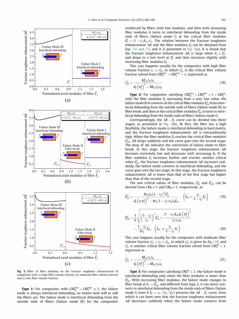
Fig. 3. Effect of fiber modulus on the fracture toughness enhancement ofcomposites with (a) high fiber volume fraction, (b) moderate fiber volume fractionand (c) low fiber volume fraction.
Y. Chen et al. / Composite Structures 122 (2015) 496–506 501
Type 1: For composites with CRIminH ¼ CRImin
S P 1, the failuremode is always interfacial debonding, no matter how stiff or softthe fibers are. The failure mode is interfacial debonding from theoutside ends of fibers (failure mode III) for the composites
reinforced by fibers with low modulus, and then with increasingfiber modulus it turns to interfacial debonding from the insideends of fibers (failure mode I) at the critical fiber modulusEC
f ¼ ð1� cf ÞEm=cf . The relation between the fracture toughnessenhancement DK and the fiber modulus Ef can be obtained fromEqs. (5) and (7), and it is presented in Fig. 3(a). It is found thatthe fracture toughness enhancement DK is large when Ef 6 EC
f ,and drops to a low level at EC
f and then increases slightly withincreasing fiber modulus Ef .
This case happens usually for the composites with high fibervolume fraction cf P cC
f 2, in which cCf 2 is the critical fiber volume
fraction solved from CRIminH ¼ CRImin
S ¼ 1, expressed as
cCf 2 ¼
8Emsbdb
df rbf
� �2þ 8Emsbdb
ð18Þ
Type 2: For composites satisfying CRIminH ¼ CRImin
S < 1 < CRIupS ,
with the fiber modulus Ef increasing from a very low value, thefailure mode first converts at the critical fiber modulus EC
f H from inter-facial debonding from the outside ends of fibers (failure mode III) tofiber break, and then at the critical fiber modulus EC
f S it turns to inter-facial debonding from the inside ends of fibers (failure mode I).
Correspondingly, the DK � Ef curve can be divided into threestages, as presented in Fig. 3(b). At first, the fiber has a highflexibility, the failure mode is interfacial debonding in hard matrix,and the fracture toughness enhancement DK is extraordinarilyhigh. When the fiber modulus Ef reaches the critical fiber modulusEC
f H, DK drops suddenly and the curve goes into the second stage.The drop of DK indicates the conversion of failure mode to fiberbreak. In this stage, the fracture toughness enhancement DKbecomes extremely low and decreases with increasing Ef. If thefiber modulus Ef increases further and reaches another criticalvalue EC
f S, the fracture toughness enhancement DK increases sud-denly, the failure mode converts to interfacial debonding, and thecurve goes into the last stage. In this stage, the fracture toughnessenhancement DK is lower than that of the first stage but higherthan that of the second stage.
The two critical values of fiber modulus, ECf S and EC
f H, can bederived from CRIS = 1 and CRIH = 1, respectively, as
ECf S ¼
4sbdb 1� cf
� 2E2m
df cf rbf
� �2� 4cf ð1� cf ÞsbdbEm
Em <cf
1� cfEf
� �ð19Þ
ECf H ¼
12
ffiffiffiffiffiffiffiffiffiffiffiffiffiffiffiffiffiffiffiffiffiffiffiffiffiffiffiffiffiffiffiffiffiffiffiffiffiffiffiffiffiffiffiffiffiffiffiffiffiffiffiffiffiffiffiffiffiffiffiffiffiffiffiffiffiffiffiffiffiffiffiffiffi1� cf
cf
� �2
E2m þð1� cf ÞEmdf rb
f
� �2
cf sbdb
vuuut� 1� cf
2cfEm Em P
cf
1� cfEf
� �ð20Þ
This case happens usually for the composites with moderate fibervolume fraction cC
f 1 < cf < cCf 2, in which cC
f 2 is given by Eq. (18) andcC
f 1 is another critical fiber volume fraction solved from CRIupS ¼ 1,
expressed as
cCf 1 ¼
4Emsbdb
df rbf
� �2þ 4Emsbdb
ð21Þ
Type 3: For composites satisfying CRIupS 6 1, the failure mode is
interfacial debonding only when the fiber modulus is lower thanEC
f H. With increasing fiber modulus, the failure mode changes tofiber break at Ef ¼ EC
f H, and different from type 2, it can never con-verts to interfacial debonding from the inside ends of fibers (failuremode I) even if Ef ?1. Fig. 3(c) presents the DK � Ef curve, fromwhich it can been seen that the fracture toughness enhancementDK decreases suddenly when the failure mode converts from
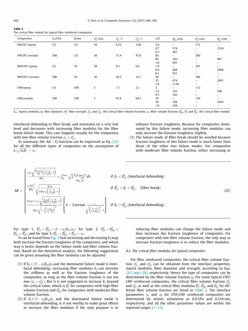
Table 2The critical fiber moduli for typical fiber reinforced composites.
Composites Em/GPa df/nm rbf =GPa cC
f 1=% cCf 2=% cf/% EC
f H=GPa ECf =GPa EC
f S=GPa
SWCNT /epoxy 3.5 2.0 50 0.53 1.06 2.0 – 172 –0.7 374 – 15540.3 467 – –
SWCNT /ceramic 300 2.0 50 31.4 47.8 60 – 200 –40 363 – 9871.0 641 – –
MWCNT /epoxy 3.5 10 30 0.3 0.6 1.0 – 347 –0.4 668 – 24680.1 931 – –
MWCNT /ceramic 300 10 30 20.3 33.7 50 – 300 –25 674 – 29011.0 1136 – –
CNF/epoxy 3.5 100 5 1.1 2.1 3 – 113 –1.5 183 – 5400.5 243 – –
CNF/ceramic 300 100 5 47.8 64.7 70 – 129 –50 198 – 32651.0 324 – –
Em: matrix modulus, df: fiber diameter, rbf : fiber strength, cC
f 1 and cCf 2: the critical fiber volume fractions, cf: fiber volume fraction, EC
f H, ECf and EC
f S: the critical fiber moduli.
502 Y. Chen et al. / Composite Structures 122 (2015) 496–506
interfacial debonding to fiber break, and maintains on a very lowlevel and decreases with increasing fiber modulus for the fiberbreak failure mode. This case happens usually for the compositeswith low fiber volume fraction cf 6 cC
f 1.In summary, the DK � Ef function can be expressed as Eq. (22)
for all the different types of composites on the assumption ofL=
ffiffiffiffiffiffiffiffiffidbdf
p!1.
DK ¼
cf db
ffiffiffiffiffiffiffiffiffiffiffiffiffiffiffiffiffiffiffiffiffiffiffiffiffiffiffiffiffiffi8Ef sbdb
cf1�cf
EfEmþ1
� �rgKIC
þR dmax
db
ffiffiffi2p
q2cf FsoftenðdÞ
gKIC
pd2f
4
dd if Ef < ECf 1 ðInterfacial debondingÞ
cf ðrbfÞ2
gKIC
ffiffiffiffiffiffiffiffiffiffiffiffiffiffiffiffiffiffiffiffiffiffiffiffiffiffiffiffiffiffidf db
2pEf sbcf
1�cf
EfEmþ1
� �sif EC
f 1 < Ef < ECf 2 ðFiber breakÞ
Emdbð1�cf Þ
ffiffiffiffiffiffiffiffiffiffiffiffiffiffiffiffiffiffiffiffiffiffiffiffiffiffiffi2sbdbpEf df
cf1�cf
EfEmþ1
� �r
gK IC
ffiffiffiffiffiffiffiffiffiffiffiffiffiffiffiffiffiffiffiffiffiffi1�
1�cfcf
EmEf
� �2r p� 2 arctan 1ffiffiffiffiffiffiffiffiffiffiffiffiffiffiffiffiffiffiffiffiffiffi
cf1�cf
EfEm
� �2
�1
r8>><>>:
9>>=>>; if Ef > EC
f 2 ðInterfacial debondingÞ
8>>>>>>>>>>>>>>>><>>>>>>>>>>>>>>>>:
ð22Þ
For type 1, ECf 1 ¼ EC
f 2 ¼ ð1� cf ÞEm=cf ; for type 2, ECf 1 ¼ EC
f H <
ECf 2 ¼ EC
f S; and for type 3, ECf 1 ¼ EC
f H < ECf 2 ¼ 1.
It can be found from Fig. 3 that increasing and decreasing Ef mayboth increase the fracture toughness of the composites, and whichway is better depends on the failure mode and fiber volume frac-tion. Based on the theoretical analysis, the following suggestionscan be given assuming the fiber modulus can be adjusted.
(1) If Ef 6 (1 � cf)Em/cf and the dominated failure mode is inter-facial debonding, increasing fiber modulus Ef can increasethe stiffness as well as the fracture toughness of thecomposites, as long as the fiber volume fraction is not toolow ðcf > cC
f 1Þ. But it is not suggested to increase Ef beyondthe critical value, which is EC
f for composites with high fibervolume fraction and EC
f H for composites with moderate fibervolume fraction.
(2) If Ef > (1 � cf)Em/cf and the dominated failure mode isinterfacial debonding, it is not worthy to make great effortsto increase the fiber modulus if the only purpose is to
enhance fracture toughness. Because for composites domi-nated by this failure mode, increasing fiber modulus canonly increase the fracture toughness slightly.
(3) The failure mode of fiber break should be avoided becausefracture toughness of this failure mode is much lower thanthose of the other two failure modes. For compositeswith moderate fiber volume fraction, either increasing or
reducing fiber modulus can change the failure mode andthus increases the fracture toughness of composites. Forcomposites with low fiber volume fraction, the only way toincrease fracture toughness is to reduce the fiber modulus.
4.2. The critical fiber modulus for typical composites
For fiber reinforced composites, the critical fiber volume frac-tion cC
f 1 and cCf 2 can be obtained from the interface properties,
matrix modulus, fiber diameter and strength, according to Eqs.(21) and (18), respectively. Hence the type of composites can bedetermined by the fiber volume fraction cf. For some typical CNT/CNF reinforced composites, the critical fiber volume fraction cC
f 1
and cCf 2 as well as the critical fiber modulus EC
f , ECf H and EC
f S for dif-ferent fiber volume fraction are listed in Table 2. The interfaceparameters sb and db for CNT/CNF reinforced composites aredetermined by atomic simulation as 6.0 GPa and 0.318 nm,respectively, and all the other parameter values are within thereported ranges [1–11].
Table 3The effects and optimal values of fiber, matrix and interface properties on fracture toughness.
Influence factor Effect and optimal value of thefactor
Fiber Fiber diameterdf
3
doptimalf ¼ dC
f ¼
4sbdbð1�cf ÞEm ½cf Efþð1�cf ÞEm �Ef ðcf rb
fÞ2
Em <cf
1�cfEf
4sbdb Ef ½cf Efþð1�cf ÞEm �Emð1�cf Þðrb
fÞ2
Em P cf
1�cfEf
8><>:
Fiber modulusEf
ð1Þ cf P 8Emsbdb
df ðrbfÞ2þ8Emsbdb
ð2Þ 4Emsbdb
df ðrbfÞ2þ4Emsbdb
< cf <8Emsbdb
df ðrbfÞ2þ8Emsbdb
ð3Þ cf 64Emsbdb
df ðrbfÞ2þ4Emsbdb
ECf ¼
ð1�cf ÞEm
cf; EC
f H ¼ 12
ffiffiffiffiffiffiffiffiffiffiffiffiffiffiffiffiffiffiffiffiffiffiffiffiffiffiffiffiffiffiffiffiffiffiffiffiffiffiffiffiffiffiffiffiffiffiffiffiffiffiffiffiffiffi1�cf
cf
� �2E2
m þEm df ð1�cf Þðrb
fÞ2
cf sbdb
r� 1�cf
2cfEm; EC
f S ¼4sbdbð1�cf Þ2 E2
m
df ðcf rbfÞ2�4cf ð1�cf Þsbdb Em
Fiber strengthrb
f rboptimalf P rbC
f ¼ð1�cf ÞEm
cf Ef
ffiffiffiffiffiffiffiffiffiffiffiffiffiffiffiffiffiffiffiffiffiffiffiffiffiffiffiffiffiffiffiffiffiffiffiffiffiffiffiffiffiffi4Ef sbdb
df
cf Ef
ð1�cf ÞEmþ 1
� �rEm <
cf
1�cfEfffiffiffiffiffiffiffiffiffiffiffiffiffiffiffiffiffiffiffiffiffiffiffiffiffiffiffiffiffiffiffiffiffiffiffiffiffiffiffiffiffiffi
4Ef sbdb
df
cf Ef
ð1�cf ÞEmþ 1
� �rEm P cf
1�cfEf
8>><>>:
Fiber volumefraction cf
ð1Þ rbf P
ffiffiffiffiffiffiffiffiffiffiffiffiffiffiffiffiffiffiffiffiffiffiffiffi8Ef sbdb=df
qð2Þ
ffiffiffiffiffiffiffiffiffiffiffiffiffiffiffiffiffiffiffiffiffiffiffiffi4Ef sbdb=df
q< rb
f <ffiffiffiffiffiffiffiffiffiffiffiffiffiffiffiffiffiffiffiffiffiffiffiffi8Ef sbdb=df
qð3Þ rb
f 6
ffiffiffiffiffiffiffiffiffiffiffiffiffiffiffiffiffiffiffiffiffiffiffiffi4Ef sbdb=df
q
coptimalð1Þf ¼ cC
f ¼Em
EmþEf; coptimalð2Þ
f ¼ cCf H ¼
Em ½df ðrbf Þ
2�4Ef sbdb �
4E2f sbdbþEm ½df ðrb
fÞ2�4Ef sbdb �
;
coptimalð3Þf is solved from @DKS jdebonding
@cf¼ 0; cC
f S ¼2Emsbdbþ
ffiffiffiffiffiffiffiffiffiffiffiffiffiffiffiffiffiffiffiffiffiffiffiffiffiffiffiffiffiffiffiffiffiffiffiffiffiffiffiffiffiffiffiffiffiffiffiffiffiffið2EmsbdbÞ2þ4sbdb df ðEmrb
fÞ2=Ef
qdf ðrb
fÞ2þ2Emsbdbþ
ffiffiffiffiffiffiffiffiffiffiffiffiffiffiffiffiffiffiffiffiffiffiffiffiffiffiffiffiffiffiffiffiffiffiffiffiffiffiffiffiffiffiffiffiffiffiffiffiffiffið2EmsbdbÞ2þ4sbdb df ðEmrb
fÞ2=Ef
q
Matrix Matrixmodulus Em
ð1Þ rbf P
ffiffiffiffiffiffiffiffiffiffiffiffiffiffiffiffiffiffiffiffiffiffiffiffi8Ef sbdb=df
qð2Þ
ffiffiffiffiffiffiffiffiffiffiffiffiffiffiffiffiffiffiffiffiffiffiffiffi4Ef sbdb=df
q< rb
f <ffiffiffiffiffiffiffiffiffiffiffiffiffiffiffiffiffiffiffiffiffiffiffiffi8Ef sbdb=df
qð3Þ rb
f 6
ffiffiffiffiffiffiffiffiffiffiffiffiffiffiffiffiffiffiffiffiffiffiffiffi4Ef sbdb=df
q
ECm ¼
ð1�cf ÞEf
cf; EC
mH ¼4cf sbdbðEf Þ2
ð1�cf Þ½df ðrbfÞ2�4Ef sbdb �
; ECmS ¼
df cf
ffiffiffiffiEf
pðrb
f Þ2
2ð1�cf Þsbdb
ffiffiffiffiEf
pþ2ð1�cf Þ
ffiffiffiffiffiffiffiffiffiffiffiffiffiffiffiffiffiffiffiffiffiffiffiffiffiffiffiffiffiffiffiffiffiffiffiffiðsbdbÞ2Ef�df sbdbðrb
fÞ2
qEoptimal
m ¼ þ1
(continued on next page)
Y. Chen et al. / Composite Structures 122 (2015) 496–506 503

Table 3 (continued)
Influence factor Effect and optimal value of thefactor
Interface Criticalinterfacialsheardisplacementdb
dCb ¼
Ef df ðcf rbf Þ
2
4sb Emð1�cf Þ½cf Efþð1�cf ÞEm � Em <cf
1�cfEf
Em df ð1�cf Þðrbf Þ
2
4sb Ef ½cf Efþð1�cf ÞEm � Em P cf
1�cfEf
8><>:
doptimalb ¼ þ1
Interfacestrength sb soptimal
b ¼ sCb ¼
Ef df ðcf rbf Þ
2
4Emdbð1�cf Þ½cf Efþð1�cf ÞEm � Em <cf
1�cfEf
Em df ð1�cf Þðrbf Þ
2
4Ef db ½cf Efþð1�cf ÞEm � Em P cf
1�cfEf
8><>:
Interfacelength L ð1Þ sb P
Ef df ðcf rbfÞ2
4Emdbð1�cf Þ½Emð1�cf ÞþEf cf � ð2Þ sb <Ef df ðcf rb
fÞ2
4Emdbð1�cf Þ½Emð1�cf ÞþEf cf �
Loptimal ð1Þ ¼ LC ¼
ffiffiffiffiffiffiffiffiffiffiffiffiffiffiffiffiffiffiffiffiffiffiffiffiffiffidb Ef df
4sb 1þcf
1�cf
EfEm
� �sln
ffiffiffiffiffiffiffiffiffiffiffiffiffiffiffiffiffiffiffiffiffiffiffiffiffiffiffiffiffiðrb
fEm Þ
2df
4sb db Ef 1þcf
1�cf
EfEm
� �vuut þ
ffiffiffiffiffiffiffiffiffiffiffiffiffiffiffiffiffiffiffiffiffiffiffiffiffiffiffiffiffiffiffiffiffiffiffiffiffiffiffiffiffiffiffiffiffiffiffiffiffiffiffiE2
m�Ef df ðr
bfÞ2 cf
1�cf
� �2
� EmEf
� �2� �
4sb db 1þcf
1�cf
EfEm
� �vuuuut
Em�rbf
ffiffiffiffiffiffiffiffiffiffiffiffiffiffiffiffiffiffiffiffiffiffiffiffifficf
1�cfEf df
4sb db1�cf
cfþ
EfEm
� �vuut
Em <cf Ef
1�cf
ffiffiffiffiffiffiffiffiffiffiffiffiffiffiffiffiffiffiffiffiffiffiffiffiffiffidb Ef df
4sb 1þcf
1�cf
EfEm
� �sln
rbf þ
ffiffiffiffiffiffiffiffiffiffiffiffiffiffiffiffiffiffiffiffiffiffiffiffiffiffiffiffiffiffiffiffiffiffiffiffiffiffiffiffiffiffiffiffiffiffiffiffiffiffiffiffiffiffiffiffiffiffiffiffiffiffiffiffiffiffiffiffiffiffiffiffiffiffi4sb db Em
1�cfcf
EmEfþ1
h ið1�cf Þ
cf df�ðrb
fÞ2
1�cfcf
EmEf
� �2
�1
� �vuutEm ð1�cf Þ
cf
ffiffiffiffiffiffiffiffiffiffiffiffiffiffiffiffiffiffiffiffiffiffiffiffiffiffiffiffi4sb dbEf df
1þcf
1�cf
EfEm
� �r�
rbf
Ef
� � Em P cf Ef
1�cf
8>>>>>>>>>>>>>>>>>>><>>>>>>>>>>>>>>>>>>>:
Loptimal ð2Þ ¼ Loptimal ð3Þ ¼ þ1
504 Y. Chen et al. / Composite Structures 122 (2015) 496–506
For SWCNT reinforced composites, when the fiber volume frac-tion cf < cC
f 2, the critical fiber modulus at transition to failure mode
III ECf or EC
f H
� �is 300–700 GPa, close to the modulus of SWCNTs. So
for these composites, increasing fiber modulus may reduce thefracture toughness significantly. However, for composites withhigh fiber volume fraction cf > cC
f 2, the critical fiber modulus is lessthan 200 GPa, much lower than the modulus of SWCNTs. So forthese composites, it is impossible to make the main failure modebecome Mode III, and it is safe to increasing fiber modulus to gainhigher composite stiffness as well as a little improvement in frac-ture toughness, as shown in Fig. 3(a).
For MWCNT reinforced composites, when the fiber volume frac-tion cf < cC
f 2, the critical fiber modulus at transition to failure modeIII is over 600 GPa, and even up to 1136 GPa, much higher than themodulus of MWCNTs. So the fracture toughness of MWCNT com-posites is far away from its optimal value, which implies thatSWCNTs are more suitable to reinforce the composite materialsfrom the view of fracture toughness enhancement if the fiber vol-ume fraction is not very high. Coincidentally, the same conclusionhas been drawn from the aspect of interwall load transfer [60].However, for composites with high fiber volume fraction cf > cC
f 2,the critical fiber modulus is around 300 GPa, very close to the mod-ulus of MWCNTs. So for this case, additional attentions should be
paid to the critical values, because a little change in fiber modulusmay lead tremendous change in the toughening effect of MWCNTsin their composites.
For CNFs reinforced composites, the critical fiber modulus at
transition to failure mode III ECf or EC
f H
� �is on the order of
102 GPa, close to the modulus of CNFs. So it may dangerous toincrease fiber modulus due to the probable sudden drop in com-posite toughness. And it should be noted that for the compositeswith ceramic matrix, the two critical fiber volume fractions areboth much higher than fiber volume fraction in present studies,which means the present CNF/ceramic composites mostly belongto type 3 (Fig. 3(c)), and thus reducing fiber modulus is the onlyway to improve composite fracture toughness.
5. Other factors influencing fracture toughness
Eqs. (5) and (7) indicates that some other properties also influ-ence the fracture toughness, including the fiber strength rb
f , fibervolume fraction cf, matrix modulus Ef and the critical shear dis-placement db. This section will investigate the effects of these fac-tors and give the analytical optimal values of these factors basedon the reasonable assumption of L=
ffiffiffiffiffiffiffiffiffidbdf
p!1. For concision, the
effects of these factors on the fracture toughness enhancement
Y. Chen et al. / Composite Structures 122 (2015) 496–506 505
DK are summarized in Table 3. The fiber diameter df and fiber stiff-ness Ef discussed above as well as the interface strength sb andinterface length L studied in Refs. [35,36] are also listed in Table 3for integrity.
As for the effect of fiber strength rbf , it can be found in Eqs. (5)
and (7) that DK increases quadratically with increase of rbf when
the failure mode is fiber break. However, if the failure mode isinterfacial debonding, rb
f has no effect on DK, and DK remains aconstant, which is higher than the maximal value of the other fail-ure mode. Therefore, the optimal DK can be achieved as long as thefailure mode is interfacial debonding, and the fiber strength rb
f thatsatisfies this failure mode condition is its optimal value, as shownin Table 3.
The effects of fiber volume fraction cf on fracture toughnessenhancement can be classified into three different types accordingto the fiber strength. (1) If the fiber strength is strong enough
rbf P
ffiffiffiffiffiffiffiffiffiffiffiffiffiffiffiffiffiffiffiffiffiffiffi8Ef sbdb=df
p� �, the failure mode is always interfacial
debonding due to the strong fiber strength, but with increasingfiber volume fraction cf, the failure mode changes from interfacialdebonding in hard matrix (failure mode III) to that in soft matrix(failure mode I) at the critical value cf = Em/(Em + Ef), where DKreaches its optimal value. (2) If the fiber strength is moderateffiffiffiffiffiffiffiffiffiffiffiffiffiffiffiffiffiffiffiffiffiffiffi
4Ef sbdb=df
p< rb
f <ffiffiffiffiffiffiffiffiffiffiffiffiffiffiffiffiffiffiffiffiffiffiffi8Ef sbdb=df
p� �, the failure mode can change
from interfacial debonding in hard matrix (failure mode III) to fiberbreak with increase of fiber volume fraction cf, and DK reaches itsoptimal value just in the transition. Then further increasing cf canmake the failure mode change to interfacial debonding in softmatrix (failure mode I), with a slight increase in DK. (3) For the
composites with fibers weak enough rbf 6
ffiffiffiffiffiffiffiffiffiffiffiffiffiffiffiffiffiffiffiffiffiffiffi4Ef sbdb=df
p� �, the
failure mode changes from fiber break to interfacial debonding insoft matrix (failure mode I) with increasing fiber volume fractioncf. The maximal value of DK and optimal value of cf can be obtainedanalytically in the stage of debonding mode by @DKS/@cf = 0 and@2DKS=@c2
f < 0 as listed in Table 3.Similar to the effect of fiber volume fraction cf, the effect of
matrix modulus Em on fracture toughness enhancement also pre-sents in three different ways according to the fiber strength, aslisted in Table 3. However, different from the effect of cf, thefracture toughness enhancement DK always increases withincreasing Em. Therefore, stiffer matrix can be toughened moreby fibers.
About the interface properties, interface strength sb and inter-face length L have already studied in Refs. [35,36]. But Eqs. (5)and (7) show that another interface parameter, the critical interfa-cial shear displacement db, can also affect DK. So db is investigatedhere for integrity. With increasing db, the failure mode can convertsfrom interfacial debonding to fiber break, but DK always increasewith db no matter of failure modes. So larger db definitely leadsto better toughening effect of fibers in composites. However, it ishardly to increase db because it depends only on the type of func-tionalization bond at the interface.
6. Conclusions
Based on the three-level failure analysis model, the effects offiber diameter on the fracture toughness of nanofiber/nanotubereinforced composites are investigated, and it is found that thinnerreinforcing fibers do not definitely confer better fracture toughnesson composites when the concept of fiber extends to nanofibers andnanotubes. With a decrease in fiber diameter, the failure mode isconverted from fiber pull-out to fiber break and the fracture tough-ness drops suddenly during this transition. The optimal fiber diam-eter is that making the failure mode just in the transition, and canbe estimated analytically by Eq. (10). Studies show that this
optimal fiber diameter is in the range of diameters of CNTs andCNFs, so ‘‘thinner is better’’ is no longer applicable for advancednano-composites.
Besides, other influence factors, including fiber stiffness, fiberstrength, fiber volume fraction, matrix modulus and the criticalinterfacial shear displacement are also studied, and a table withthe effects of fiber, matrix and interface properties as well as theiroptimal values are provided, which has guiding significance for theadvanced composite material design. It should be noted that thetheoretical analysis and analytical solutions obtained in this studycan also be extended to composites reinforced by conventionalfibers, such as the widely-used carbon fibers and glass fibers.
Acknowledgements
Supports by the National Natural Science Foundation of China(Nos. 11202012 and 11472027) and the Program for New CenturyExcellent Talents in University (No. NCET-13-0021) are gratefullyacknowledged.
References
[1] Tibbetts GG, Lake ML, Strong KL, Rice BP. A review of the fabrication andproperties of vapor-grown carbon nanofiber/polymer composites. Compos SciTechnol 2007;67:1709–18.
[2] Hammel E, Tang X, Trampert M, Schmitt T, Mauthner K, Eder A, et al. Carbonnanofibers for composite applications. Carbon 2004;42:1153–8.
[3] Huang ZM, Zhang YZ, Kotakic M, Ramakrishn S. A review on polymernanofibers by electrospinning and their applications in nanocomposites.Compos Sci Technol 2003;63:2223–53.
[4] Kim JS, Reneker DH. Mechanical properties of composites using ultrafineelectrospun fibers. Polym Compos 1999;20:124–31.
[5] Baji A, Mai YW, Wong SC, Abtahi M, Chen P. Electrospinning of polymernanofibers: effects on oriented morphology, structures and tensile properties.Compos Sci Technol 2010;70:703–18.
[6] Baughman RH, Zakhidov AA, Heer WA. Carbon nanotubes: the route towardapplications. Science 2002;297:787–92.
[7] Chen YL, Liu B, Wu J, Huang Y, Jiang H, Hwang KC. Mechanics of hydrogenstorage in carbon nanotubes. J Mech Phys Solids 2008;56:3224–41.
[8] Yin Y, Chen YL, Yin J, Huang KC. Geometric conservation laws for Y-branchedcarbon nanotubes. Nanotechnology 2006;17:1–5.
[9] De Volder MFL, Tawfick SH, Baughman RH, Hart AJ. Carbon nanotubes: presentand future commercial applications. Science 2013;393:535–9.
[10] Yu MF, Files BS, Arepalli S, Ruoff RS. Tensile loading of ropes of single-wallcarbon nanotubes and their mechanical properties. Phys Rev Lett 2000;84:5552–5.
[11] Yu MF, Lourie O, Dyer MJ. Strength and breaking mechanism of multiwalledcarbon nanotubes under tensile load. Science 2000;287:637–40.
[12] Allaoui A, Bai S, Cheng H, Bai J. Mechanical and electrical properties of aMWCNT/epoxy composite. Compos Sci Technol 2002;62:1993–8.
[13] Bai J, Allaoui A. Effect of the length and the aggregate size of MWNTs on theimprovement efficiency of the mechanical and electrical properties ofnanocomposites experimental investigation. Composite Part A 2003;34:689–94.
[14] Gojny F, Wichmann M, Fiedler B, Bauhofer W, Schulte K. Influence of nano-modification on the mechanical and electrical properties of conventional fibre-reinforced composites. Composite Part A 2005;36:1525–35.
[15] Zhou Y, Wu P, Cheng Z, Ingram J, Jeelani S. Improvement in electrical, thermaland mechanical properties of epoxy by filling carbon nanotubes. ExpressPolym Lett 2008;2:40–8.
[16] Moniruzzaman M, Du FM, Romero N, Winey KI. Increased flexural modulusand strength in SWNT/epoxy composites by a new fabrication method.Polymer 2006;47:293–8.
[17] Gojny FH, Wichmann MHG, Fiedler B, Schulte K. Influence of different carbonnanotubes on the mechanical properties of epoxy matrix composites–acomparative study. Compos Sci Technol 2005;65:2300–13.
[18] Gojny FH, Wichmann MHG, Kópke U, Fiedler B, Schulte K. Carbon nanotubereinforced epoxy-composites: enhanced stiffness and fracture toughness atlow nanotube volume fraction. Compos Sci Technol 2004;64:2363–71.
[19] Yang BX, Shi JH, Pramoda KP, Goh SH. Enhancement of stiffness, strength,ductility and toughness of poly (ethylene oxide) using phenoxy-graftedmultiwalled carbon nanotubes. Nanotechnology 2007;18:1–7. 125606.
[20] Fiedler B, Gojny FH, Wichmann MHG, Nolte MCM, Schulte K. Fundamentalaspects of nano-reinforced composites. Compos Sci Technol 2006;66:3115–25.
[21] Dondero WE, Gorga RE. Morphological and mechanical properties of carbonnanotube/polymer composites via melt compounding. J Polym Sci Pol Phys2006;44:864–78.
[22] Tang LC, Wan YJ, Peng K, Pei YB, Wu LB, Chen LM, et al. Fracture toughness andelectrical conductivity of epoxy composites filled with carbon nanotubes andspherical particles. Composite Part A 2013;45:95–101.

506 Y. Chen et al. / Composite Structures 122 (2015) 496–506
[23] Ma PC, Kim JK, Tang BZ. Effects of silane functionalization on the properties ofcarbon nanotube/epoxy nanocomposites. Compos Sci Technol 2007;67:2965–72.
[24] Bauhofer W, Kovacs WJZ. A review and analysis of electrical percolation incarbon nanotube polymer composites. Compos Sci Technol 2009;69:1486–98.
[25] Kwon SY, Kwon IM, Kim YG, Lee S, Seo YS. A large increase in the thermalconductivity of carbon nanotube/polymer composites produced by percolationphenomena. Carbon 2013;55:285–90.
[26] Bozlar M, He MDL, Bai JB, Chalopin Y, Mingo YN, Volz S. Carbon nanotubemicroarchitectures for enhanced thermal conduction at ultralow mass fractionin polymer composites. Adv Mater 2010;22:1654–8.
[27] Han ZD, Fina A. Thermal conductivity of carbon nanotubes and their polymernanocomposites: a review. Prog Polym Sci 2011;36:914–44.
[28] Chen XY, Beyerlein IJ, Brinson LC. Curved-fiber pull-out model fornanocomposites. Part 1: bonded stage formulation. Mech Mater 2009;41:279–92.
[29] Chen XY, Beyerlein IJ, Brinson LC. Curved-fiber pull-out model fornanocomposites. Part 2: interfacial debonding and sliding. Mech Mater2009;41:293–307.
[30] Chen XY, Beyerlein IJ, Brinson LC. Bridged crack models for the toughness ofcomposites reinforced with curved nanotubes. J Mech Phys Solids 2011;59:1938–52.
[31] Pavia F, Curtin WA. Optimizing strength and toughness of nanofiber-reinforced CMCs. J Mech Phys Solids 2012;60:1688–702.
[32] Li LL, Xia ZH, Curtin WA, Yang YQ. Molecular dynamics simulations ofinterfacial sliding in carbon-nanotube/diamond nanocomposites. J Am CeramSoc 2009;92(10):2331–6.
[33] Pavia F, Curtin WA. Interfacial sliding in carbon nanotube/diamond matrixcomposites. Acta Mater 2011;59:6700–9.
[34] Pavia F, Curtin WA. Molecular modeling of cracks at interfaces in nanoceramiccomposites. J Mech Phys Solids 2013;61:1971–82.
[35] Chen YL, Liu B, He XQ, Huang Y, Hwang KC. Failure analysis and the optimaltoughness design of carbon nanotube-reinforced composites. Compos SciTechnol 2010;70:1360–7.
[36] Chen YL, Liu B, Huang Y, Hwang KC. Fracture toughness of carbon nanotube-reinforced metal- and ceramic-matrix composites. J Nanomater 2011;746029:1–9.
[37] Tang LC, Zhang H, Han JH, Wu XP, Zhang Z. Fracture mechanisms of epoxyfilled with ozone functionalized multi-wall carbon nanotubes. Compos SciTechnol 2011;72(1):7–13.
[38] Tang LC, Zhang H, Wu XP, Zhang Z. A novel failure analysis of multi-walledcarbon nanotubes in epoxy matrix. Polymer 2011;52(9):2070–4.
[39] Lin Z, Li VC. Crack bridging in fiber reinforced cementitious composites withslip-hardening interfaces. J Mech Phys Solids 1997;45(5):763–87.
[40] Fisher FT, Bradshaw RD, Brinson LC. Effects of nanotube waviness on themodulus of nanotube reinforced polymers. Appl Phys Lett 2002;80(24):4647–9.
[41] Wong SC, Baji A, Leng SW. Effect of fiber diameter on tensile properties ofelectrospun poly (-caprolactone). Polymer 2008;49:4713–22.
[42] Arinstein A, Burman M, Gendelman O, Zussman E. Effect of supramolecularstructure on polymer nanofibre elasticity. Nat Nanotechnol 2007;2:59–62.
[43] Chen F, Peng XW, Li TT, Chen SL, Wu XF, Reneker DH, et al. Mechanicalcharacterization of single high-strength electrospun polyimide nanofibres. JPhys D Appl Phys 2008;41(025308):1–8.
[44] Chen SY, Hufnagel TC, Lim CT, Leong KW. Mechanical properties of singleelectrospun drug-encapsulated nanofibres. Nanotechnology 2006;17(15):3880–91.
[45] Dingreville R, Qu RJM, Cherkaoui M. Surface free energy and its effect on theelastic behavior of nano-sized particles, wires and films. J Mech Phys Solids2005;53:1827–54.
[46] Cox HL. The elasticity and strength of paper and other fibrous materials. Br JAppl Phys 1952;3(1):72–9.
[47] Chon TW, Sun CT. Stress distributions along a short fiber in fiber reinforcedplastics. J Mater Sci 1980;15(4):931–8.
[48] Lawrence P. Some theoretical considerations of fiber pull-out from an elasticmatrix. J Mater Sci 1972;7(1):1–6.
[49] Marshall DB, Cox BN, Evans AG. The mechanics of matrix cracking in brittle-matrix fiber composites. Acta Metall 1985;33(11):2013–22.
[50] Hutchinson JW, Jensen HM. Models of fiber debonding and pullout in brittlecomposites with friction. Mech Mater 1990;9:139–63.
[51] Budiansky B, Evans AG, Hutchinson JW. Fiber-matrix debonding effects oncracking in aligned fiber ceramic composites. Int J Solids Struct 1995;32:315–28.
[52] Qian D, Dickey EC, Andrews R, Rantell T. Load transfer and deformationmechanisms in carbon nanotube-polystyrene composites. Appl Phys Lett2000;76(20):2868–70.
[53] Anderson TL. Fracture mechanics: fundamentals and applications. BocaRaton: CRC Press LLC; 1995.
[54] Tada H, Paris PC, Irwin GR. The stress analysis of cracks handbook. 3rd ed. NewYork: ASME Press; 2000.
[55] Al-Saleh MH, Sundararaj U. Review of the mechanical properties of carbonnanofiber/polymer composites. Composite Part A 2011;42:2126–42.
[56] Arshad SN, Naraghi M, Chasiotis I. Strong carbon nanofibers from electrospunpolyacrylonitrile. Carbon 2011;49:1710–9.
[57] Feng LC, Xie N, Zhong J. Carbon nanofibers and their composites: a review ofsynthesizing, properties and applications. Materials 2014;7:3919–45.
[58] Namat-Nasser S, Hori M. Micromechanics: overall properties of heterogeneousmaterials. North-holland series in applied mathematics and mechanicsseries. Elsevier; 1993.
[59] Escamilla CG, Laviada RJ, Cupul CJI, Mendizába E, Puig JE, Franco HPJ. Flexural,impact and compressive properties of a rigid-thermoplastic matrix/cellulosefiber reinforced composites. Composites Part A 2002;33:539–49.
[60] Chen YL, Liu B, Hwang KC, Huang YG. A theoretical evaluation of load transferin multi-wall carbon nanotubes. Carbon 2011;49(1):193–7.
Related Documents