Effects of conjugated polymer on the magnetotransport properties in La0.7Sr0.3MnO3 ferromagnetic electrodes M. Pesonen, S. Majumdar, H. Huhtinen, P. Paturi, H. S. Majumdar et al. Citation: AIP Advances 3, 042102 (2013); doi: 10.1063/1.4800907 View online: http://dx.doi.org/10.1063/1.4800907 View Table of Contents: http://aipadvances.aip.org/resource/1/AAIDBI/v3/i4 Published by the AIP Publishing LLC. Additional information on AIP Advances Journal Homepage: http://aipadvances.aip.org Journal Information: http://aipadvances.aip.org/about/journal Top downloads: http://aipadvances.aip.org/features/most_downloaded Information for Authors: http://aipadvances.aip.org/authors Downloaded 28 Sep 2013 to 202.108.50.75. All article content, except where otherwise noted, is licensed under a Creative Commons Attribution 3.0 Unported license. See: http://creativecommons.org/licenses/by/3.0/

Welcome message from author
This document is posted to help you gain knowledge. Please leave a comment to let me know what you think about it! Share it to your friends and learn new things together.
Transcript

Effects of conjugated polymer on the magnetotransport properties inLa0.7Sr0.3MnO3 ferromagnetic electrodesM. Pesonen, S. Majumdar, H. Huhtinen, P. Paturi, H. S. Majumdar et al. Citation: AIP Advances 3, 042102 (2013); doi: 10.1063/1.4800907 View online: http://dx.doi.org/10.1063/1.4800907 View Table of Contents: http://aipadvances.aip.org/resource/1/AAIDBI/v3/i4 Published by the AIP Publishing LLC. Additional information on AIP AdvancesJournal Homepage: http://aipadvances.aip.org Journal Information: http://aipadvances.aip.org/about/journal Top downloads: http://aipadvances.aip.org/features/most_downloaded Information for Authors: http://aipadvances.aip.org/authors
Downloaded 28 Sep 2013 to 202.108.50.75. All article content, except where otherwise noted, is licensed under a Creative Commons Attribution 3.0 Unported license.See: http://creativecommons.org/licenses/by/3.0/

AIP ADVANCES 3, 042102 (2013)
Effects of conjugated polymer on the magnetotransportproperties in La0.7Sr0.3MnO3 ferromagnetic electrodes
M. Pesonen,1,a S. Majumdar,2 H. Huhtinen,2 P. Paturi,2 H. S. Majumdar,1,3
and R. Osterbacka1
1Center for Functional Materials, Physics, Department of Natural Sciences, Åbo AkademiUniversity, 20500 Turku, Finland2Wihuri Physical Laboratory, Department of Physics and Astronomy, University of Turku,20014 Turku, Finland3VTT Technical Research Center of Finland, 02150 Espoo, Finland
(Received 22 November 2012; accepted 26 March 2013; published online 3 April 2013)
Magnetotransport of La0.7Sr0.3MnO3 (LSMO)/regioregular poly3-hexylthiophene(rr-P3HT) interfaces were studied at 5–300 K to gain insight of spin transport inpolymer coated LSMO. LSMO films on SrTiO3 (STO), MgO, and quartz substrateswere characterized in pristine state, after depositing rr-P3HT and after removingrr-P3HT. Application and removal of rr-P3HT caused the disappearance of colos-sal magneto resistance and the emerging of low-field magnetoresistance (LFMR)in STO/LSMO, while the same treatment on MgO and quartz showed only a largeLMFR signal with no significant changes during application and removal of rr-P3HT.This result signifies that epitaxial thin films of LSMO do not maintain their trans-port characteristics when coated with organic semiconductors, posing a limitation forefficient spin polarized injection at such interfaces. Copyright 2013 Author(s). Allarticle content, except where otherwise noted, is licensed under a Creative CommonsAttribution 3.0 Unported License. [http://dx.doi.org/10.1063/1.4800907]
Spintronics based on carbon-based materials, especially organic semiconductors (OSCs), isgaining importance due to the advantages of weak spin-orbit coupling and hyperfine interactionof these materials.1, 2 Such fundamental physical properties make these materials possibly betteralternatives to their inorganic counterparts in transporting polarized spins with a caveat that mobilityof carriers also have an important role to play in this context.3 Their soft lattice structure and capabilityof reorganizing the structure also provide an opportunity to form a good interface with a ferromagnetic(FM) metal or half-metal, reducing the probability of spin scattering at the interface. Spin transportcould even be better in polymers than small molecules because of their conjugation over an extendedchain compared to the small molecules, leading to improved charge carrier mobility.4, 5 Easy solution-processibility and simple device fabrication techniques e.g. spin coating and drop casting, also givean edge in terms of application. However, as of to date the fact that spin injection occurs frommetals/half-metals into organics is a highly debated topic. There have been numerous reports onlimitations, caused by e.g. Schottky barriers, formation of spin-less bipolarons and Fermi levelpinning due to localized states,6–8 regarding efficient spin polarized (SP) injection from inorganicsinto organics. This debate has enforced the need for more detailed studies of organic/inorganicinterfaces and their ability to affect spin transport and injection.
The half metallic manganite La0.7Sr0.3MnO3 (LSMO) has been utilized as the spin injectingelectrode in inorganic/organic spintronic devices.9–11 The advantage of LSMO is the 100% spinpolarized (SP) conduction band at low temperature compared to only 30–40% SP carriers at theFermi energy in conventional magnetic metals such as Fe, Co, Ni, etc. Also LSMO, being a stableoxide, is less reactive than transition metals and thus the resulting interface with the OSCs is more
aAuthor to whom correspondence should be addressed. Electronic mail: [email protected]
2158-3226/2013/3(4)/042102/8 C© Author(s) 20133, 042102-1
Downloaded 28 Sep 2013 to 202.108.50.75. All article content, except where otherwise noted, is licensed under a Creative Commons Attribution 3.0 Unported license.See: http://creativecommons.org/licenses/by/3.0/
042102-2 Pesonen et al. AIP Advances 3, 042102 (2013)
stable. The Curie temperature (TC ≈ 370 K) of bulk LSMO lies well above room temperature,however, depending on deposition parameters of the LSMO films, magnetotransport properties canvary from that of the bulk value appreciably.
The magnetotransport properties in LSMO are controlled by the double-exchange (DE) mecha-nism i.e. transfer of eg electrons between the Mn3+ and Mn4+ ions through the intermediate O ions ofthe MnO6 octahedra. DE interaction can be significantly influenced by structural defects and strainsdue to lattice mismatch between the substrate and the pulsed laser deposited (PLD) thin films.12
Increased lattice mismatch between the LSMO and substrate lattice results in structural strain ofLSMO unit cells resulting in deteriorated crystalline properties and grain boundary (GB) relateddefects. The strained LSMO lattice manifests as polycrystalline films, where the carrier motionunder magnetic field is controlled by the low-field magnetoresistance (LFMR) phenomenon, i.e.,tunneling of spin-polarized (SP) electrons between ferromagnetic (FM) grains through GBs. Henceit is expected that a single crystalline, epitaxial LSMO film is the best choice for spintronic devices.However, our earlier experiment showed that even a best quality single crystalline LSMO film isunable to improve the magnetoresistance response of the spin-valves.13
This prompted our attempt to further investigate the role of LSMO/OSC interface in injectingpolarized spins in the device with varying crystalline properties and consequently different mag-netotransport properties of LSMO. In the present article, we report the effect regioregular poly3-hexylthiophene (rr-P3HT) has on the magnetotransport properties of the LSMO. Characterizationof the temperature and magnetic field dependent change in resistance, with the addition and removalof rr-P3HT coatings, will determine the spin transport properties of LSMO at the rr-P3HT interface.
LSMO samples of 130 nm thickness were deposited using optimized PLD parameters13 ontothree different substrates, magnesium oxide (MgO), strontium titanate (STO) and quartz. The struc-tures of the films were determined with x-ray diffraction (XRD) using a Philips X’pert Pro MPDdiffractometer with a Schulz goniometer. In the incident beam path Ni filter, 0.04 rad Soller slit and1 × 4 mm slits were used and in the reflected beam path a 0.19◦ thin film collimator and 0.04 radSoller slit were used. The phase purity of the films was determined from θ -2θ -scans. The texturing ofthe films was determined by measuring a pole figure of the pseudocubic (110) peaks at 32.80◦ for thesample on MgO and quartz and, due to overlapping substrate peak, the pole figure of rhomboedric(113) peak at 38.60◦ was used for the sample on STO. The pseudocubic lattice parameters weredetermined from detailed scans of (200) peaks. Also the peak widths were determined from thesemeasurements to estimate straining in each sample.
The samples were cut to size (5 × 5 mm2) and mounted to a sample holder and it was placed ina vacuum sealed cryostat and pumped overnight before measuring. The cryostat was placed betweenthe pole pieces of an electromagnet capable of producing a magnetic field up to 300 mT. Thesample resistance was then measured for a constant bias current through the device, whilst varyingthe magnetic field (B), in the temperature range 5–300 K. For each scan, B was first stabilized,then current was sent through the sample and the corresponding voltage was measured. In ourmeasurements, B was scanned from +300 mT to −300 mT and back to +300 mT with varyingsweeping rates. The resulting magnetoresistance (MR) in percent was calculated using equation (1):
%MR = 100 × R(B) − R(0)
R(0), (1)
where %MR is the magnetoresistance in %, R(B) is the field dependent resistance signal and R(0)is the zero field resistance measured over the device.
Each of the three different samples was characterized under three different conditions. First thesamples were characterized under pristine conditions, i.e. no treatment of the LSMO film. Then thesamples were coated with rr-P3HT for another measurement and lastly the samples were cleanedmechanically and with acetone for the final characterization. For the first measurement, two contactswere glued with silver paste on opposite corners of the sample. For the second measurement, thesilver paste was not removed from the LSMO surface before coating it with rr-P3HT to enablebetter cleaning of the contact area. The rr-P3HT was spin coated on top of the LSMO film andbefore the film was annealed, the two contacts were cleaned. The rr-P3HT film was then annealedat 80 ◦C for 15 minutes. For the final measurement the rr-P3HT film was peeled off and any
Downloaded 28 Sep 2013 to 202.108.50.75. All article content, except where otherwise noted, is licensed under a Creative Commons Attribution 3.0 Unported license.See: http://creativecommons.org/licenses/by/3.0/

042102-3 Pesonen et al. AIP Advances 3, 042102 (2013)
TABLE I. Lattice parameters and peak widths for LSMO covered STO, MgO and quartz substrates.
Substrate 2θ [◦] a [Å] FWHM [◦]
STO 46.494 3.903 0.140MgO 46.405 3.910 0.408quartz 47.365 3.835 0.595
FIG. 1. X-ray diffraction pole figures of a) STO/LSMO, b) MgO/LSMO and c) quartz/LSMO films.
residual rr-P3HT was cleaned off with acetone. To protect the contacts from the solvents usedand from mechanical wear they were coated with an epoxy layer, which enabled non-varyingcontact resistances between measurements. After removing the rr-P3HT layer, x-ray photoelectronspectroscopy (XPS) measurements were performed on the film to probe traces of any residualelements left on the surface of LSMO.
Figure 1 shows XRD pole figures of pristine LSMO films deposited on three different substrates.In θ -2θ scans all the films showed only (00l) peaks of LSMO in addition to the substrate peaks.Therefore we can conclude that the samples are phase pure and c-axis oriented. The sample on STO(Fig. 1(a)) is perfectly textured and it is very difficult to separate the substrate and film peaks. Thesample on MgO (Fig. 1(b)), on the other hand, has quite wide peaks indicating a large number of lowangle GBs. The peak width in ϕ is 5.1◦, which directly implies low angle GBs with misorientationangles of the same magnitude. Contrary to the samples on MgO and STO, the sample on quartz(Fig. 1(c)) shows only uniaxial texturing with grains oriented in all ϕ-directions. This implies largeamount of high angle GBs in the quartz sample. The determined lattice parameters and peak widthsare shown in Table I. The straining of the film on STO could not be determined due to the perfectoverlap with the substrate and the peak width thus represents the instrumental widening. Because allthe peak intensities of the film on quartz are very low compared to the other samples, it is possiblethat this sample contains at least some amorphous material between the grains.
Figures 2(a)–2(c) depict the magnetic field dependent %MR response for LSMO films on STO(producing single crystalline LSMO), MgO and quartz (both producing polycrystalline LSMO)substrates at 5 K in the field range ±300 mT. Figure 3 show resistance hysteresis loops close tothe magnetic coercive fields (BC) of the STO films, consistent with LFMR. All the pristine LSMOsamples showed clear negative MR signal for higher fields than their respective Bc values. Themagnitude of %MR in the measured field range is highest in MgO/LSMO and lowest in STO/LSMO,as expected from the degree of crystal-matching between the substrate and LSMO. Resistance peaks(smallest for STO and biggest for MgO and quartz) were seen close to BC for all films, indicatingGB tunneling MR response in these LSMO films indicative of deteriorated crystalline properties, insupport of the XRD-characterization. In addition to the LFMR response, LSMO films show clearsignature of colossal magnetoresistance (CMR) response, i.e. the line-shape in Fig. 2, at highermagnetic fields which is mainly caused by suppression of carrier scattering at the defect sites by theapplication of magnetic fields.14
The %MR signal decreases after the addition of the rr-P3HT coating for all LSMO films. Beforewe discuss the change of the %MR signal in the LSMO/rr-P3HT structure we have to note thatpure rr-P3HT has a distinct positive MR response.15, 16 Hence, the resulting %MR signal of the
Downloaded 28 Sep 2013 to 202.108.50.75. All article content, except where otherwise noted, is licensed under a Creative Commons Attribution 3.0 Unported license.See: http://creativecommons.org/licenses/by/3.0/

042102-4 Pesonen et al. AIP Advances 3, 042102 (2013)
FIG. 2. The %MR vs. magnetic field, at 5 K, for LSMO deposited on a) STO, b) MgO and c) quartz substrates. The blackplots designated with only the substrate name are for pristine LSMO films, the red plots with the suffix P3HT denotes rr-P3HTcoated LSMO films and the green plots with suffix R denotes LSMO films after removal of the rr-P3HT coating.
FIG. 3. The LFMR peaks, at 5 K, for a) STO/LSMO, b) STO/LSMO/rr-P3HT and c) STO/LSMO/R (cleaned from rr-P3HT).
rr-P3HT coated LSMO could be a superposition of both the negative MR response of LSMO andthe positive MR response of the rr-P3HT layer. Though the fact that rr-P3HT has a high resistanceat low temperatures makes charge transport through rr-P3HT improbable. However, there might bean effective dipole-field formed16 from interfacial dipoles, including Fermi-level pinning,17 leadingto an altered electronic structure of LSMO and hence a quenched MR response. In all the films
Downloaded 28 Sep 2013 to 202.108.50.75. All article content, except where otherwise noted, is licensed under a Creative Commons Attribution 3.0 Unported license.See: http://creativecommons.org/licenses/by/3.0/

042102-5 Pesonen et al. AIP Advances 3, 042102 (2013)
(Fig. 2) the %MR signal quenches due to this combined effect. These interfacial dipoles originatefrom interactions between the LSMO surface and rr-P3HT and may be in the form of chemicalbonds or van der Waals forces acting at the interface. There may also be oxygen doping of LSMOat the interface, disrupting the electron configuration, facilitated by rr-P3HT.
Furthermore, when the rr-P3HT layer was removed the %MR changed again. In thequartz/LSMO and MgO/LSMO films (Fig. 2(b) and 2(c)) the %MR signal was either partially re-covered (quartz/LSMO) or remained largely unchanged (MgO/LSMO). However, further anomalywas observed in the STO/LSMO film. A huge increase, nearly by a factor of 10, in the %MR isobserved in the case of STO/LSMO films (Fig. 2(a)), leading to higher %MR signal in the cleanedfilm than in the pristine film.
We hypothesize the changes as follows. Due to the single crystalline nature of STO/LSMO,the effect of GBs, in surface and bulk, is much smaller in these pristine films compared to theother two films leading to less scattering of carriers at the GBs, causing a much smaller %MR. Theimproved crystalline structure also results in undistorted MnO6 octahedra of LSMO which favorsdelocalization of eg electrons and hence the DE interaction, and conductivity improves. Due to asmall amount of GB defects, LFMR response caused by GB tunneling is expected to be less in thesefilms compared to the other two. We propose that by the addition and removal of a rr-P3HT coatingon the STO/LSMO surface, GB like defects are introduced on the LSMO surface. This results inan increase in GB related effects such as an increased LFMR, higher %MR response as well as anoverall increased resistance value. The rr-P3HT coating may even penetrate into the LSMO filmvia existing GBs and/or hairy fractures. But, in case of quartz/LSMO and MgO/LSMO the effectis different. There are already sufficient low- and high-angle GBs in these films due to crystalmismatch, so that, the introduction GB like defects has no further impact on the LFMR. In thesecases the quenching of the MR signal, arising from the addition of a rr-P3HT coating, is partiallyrestored upon removal of the rr-P3HT coating.
The resistance (measured at 1 μA) of the LSMO films also increased after applying the rr-P3HTcoating, from 149 � to 48.5 k� for STO/LSMO, from 673 k� to 3.8 M� for MgO/LSMO and from7.1 M� to 14.4 M� for quartz/LSMO. Single crystalline LSMO has a much lower bulk resistance(in the order of a few � at 5 K)18 than polycrystalline LSMO (in the order of a few k� at 5 K)18
and if the single crystallinity is destroyed by the addition of a rr-P3HT coating the change in theresistance should be greater for the STO/LSMO film than for the MgO/LSMO and quartz/LSMOfilms, as was observed in our case. The change in resistance for STO/LSMO can also stem fromdisruption of the electron configuration, not related to GB defects, hindering DE interaction and thusthe spin and charge transport. Possible causes for this disruption could be e.g. formation of surfacedipoles and doping. After the removal of the rr-P3HT coating, all resistances remained elevated andeven increased in the case of STO for small currents. However, we should also consider the fact thateven if rr-P3HT introduces defects on the LSMO surface the bulk resistivity of LSMO should notchange, unless the interaction surface, i.e. the effective LSMO/rr-P3HT interface already penetratesdeep into the bulk e.g. in the form of enhanced GBs and/or hairy fractures. The use of solvents whenremoving the rr-P3HT coating might also facilitate deeper penetration of rr-P3HT into the existingfractures and/or GBs.
It has previously been shown that even after cleaning the rr-P3HT layer with acetone andisopropyl alcohol some residual rr-P3HT stay attached to the LSMO surface, detected via sulfurremnants.19 In the present case no trace of sulfur was found by post-cleaning XPS measurements, inthe instrumental detection limit (0.1–1 atomic %). The reason for this discrepancy can be attributedto the difference in the quality of the LSMO films used in Ref. 19 and the present study. The LSMOsamples in Ref. 19 were thicker and thus the surface RMS roughness was much higher (≈15 nm) inthem than the ones used here (≈4 nm). A rougher LSMO film might lead to a better surface for therr-P3HT film to stick to and be detectable with XPS measurements. However, higher resistance ofLSMO films after removal of the rr-P3HT coating clearly indicates that some surface modification inLSMO, likely both in surface and bulk GB regions, takes place after application of rr-P3HT, whichis beyond the detection limit of XPS.
To further clarify the changing in resistance, dV/d(ln I) was calculated for STO/LSMO andMgO/LSMO samples at 5 K and 300 K and plotted for 5 K in Fig. 4. The quartz/LSMO samples
Downloaded 28 Sep 2013 to 202.108.50.75. All article content, except where otherwise noted, is licensed under a Creative Commons Attribution 3.0 Unported license.See: http://creativecommons.org/licenses/by/3.0/

042102-6 Pesonen et al. AIP Advances 3, 042102 (2013)
FIG. 4. The derivative of the voltage with respect to logarithmic current for a) STO/LSMO and b) MgO/LSMO, both at 5 K.
did not yield linear dV/d(ln I) plots, attributed to their already extensive disorder and have beenleft out from further discussions. The plot clearly shows the variation of dV/d(ln I) in LSMO onMgO/LSMO and STO/LSMO measured at 5 K both before and after rr-P3HT deposition and afterremoval. It has been previously shown that one can estimate the ideality factor (n) from a dV/d(ln I)plot using the equation and method proposed by Cheung and Cheung:20
d V
d lnI= n
kT
q+ RSI, (2)
where k is the Boltzmann constant, T the absolute temperature, q the electron charge, and RS theseries resistance. The ideality factor indicates how close a device is to an ideal diode (where n =1), indicating how good the injection and charge transport is. The ideality factor is usually betweenone and two, however, if the equation is applied to a device with no injection barriers it is no longervalid, because the Schottky diode equation from which equation (2) is derived from is no longervalid, and it will result in an apparent n < 1. An ideality factor greater than 2 may indicate thepresence of an amorphous, transport limiting layer governed by Poole-Frenkel conduction.21 Theideality factor calculated from Fig. 4 for MgO/LSMO was found to be much larger than 2 at 5 K, bothbefore and after the rr-P3HT treatment. Whereas the ideality factor for pristine STO was found to besignificantly smaller than 1 at 5 K, indicating injection barrier free transport, and it increased whensubjected to rr-P3HT treatment. The ideality factor for STO increased further after the removal ofrr-P3HT, reaching an approximate value of 5. The same trend applies for STO at 300 K, except thatthe increase was not that prominent. These results could imply the inclusion of rr-P3HT in existingGBs and hairy fractures already present in the pristine STO film, and that rr-P3HT penetrates deeperinto these defects while being removed, due to the solvents used in the cleaning process, creatingregions of poorly conducting rr-P3HT barriers in the film.
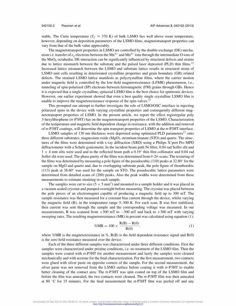
To support our findings regarding the influence of LFMR over CMR in STO/LSMO films,the absolute %MR (|%MR|) response was plotted as a function of temperature, as seen in Fig. 5.The temperature dependence of CMR gives rise to an increasing |%MR| response with respect toincreasing temperature, showing a peak close to TC as seen in Fig. 5(a) (pristine STO curve). TheLFMR response follows an inverse temperature dependence, i.e. the |%MR| response increases withdecreasing temperature showing a maximum at 5 K, as clearly seen in Fig. 5(b) and 5(c). Therr-P3HT-treated and cleaned STO/LSMO films clearly show a shift in the |%MR| peak, moving ittowards lower temperatures. However, the MR vs. temperature plot corresponds to neither purelyCMR nor completely LFMR behavior. The shape of the temperature dependent |%MR| curve for therr-P3HT coated and cleaned films in Fig. 5(a) suggest superposition of CMR and LFMR phenomenonin this film. If the MR in LSMO would be governed by CMR only then would we have observedan increasing |%MR| response with respect to an increasing temperature (line shape for both CMR
Downloaded 28 Sep 2013 to 202.108.50.75. All article content, except where otherwise noted, is licensed under a Creative Commons Attribution 3.0 Unported license.See: http://creativecommons.org/licenses/by/3.0/
042102-7 Pesonen et al. AIP Advances 3, 042102 (2013)
FIG. 5. The absolute %MR (|%MR|) vs. temperature is plotted for LSMO deposited on a) STO, b) MgO and c) quartzsubstrates. The black plots designated with only the substrate name are for pristine LSMO films, the red plots with the suffixP3HT denotes rr-P3HT coated LSMO films and the green plots with suffix R denotes LSMO films after removal of therr-P3HT coating.
and rr-P3HT added together). The fact that the maximum is observed around 100-150 K indicatesthat the magnetotransport in STO/LSMO has not fully changed from CMR to LFMR i.e. the LFMRsignal is not strong enough to completely overshadow the CMR signal.
To rule out the fabrication process as being the reason for the observed changes in MR andresistance, control measurements were carried out under identical conditions with the exceptionof only using the polymer solvent (Chlorobenzene) at the application step. The results from thecontrol experiment showed no changes in the resistance or in the MR of the samples (not shownhere), further proving the impact of P3HT on the interfacial charge and spin transport, togetherwith the fact that the contact resistance remained unchanged throughout the experiment. To verifywhether actual changes in the grain structure of LSMO occurred, XRD studies were carried out onpost-cleaned samples. However, the treated samples showed no significant changes in their XRDdata so we cannot conclude that changes in their grain structure occurred even though the changefrom CMR to LFMR and the change in resistance support an increase in GB like defects. However,a change in the depth of the previously proposed hairy fractures and/or GB present in the pristineLSMO film would not show up on XRD, and therefore their involvement in determining the transportcannot neglected. The growth of these defects could e.g. emulate enhanced GB defects.
Hence, from the above experiments we can conclude that coating and removal of rr-P3HTintroduces more GB like defects on the LSMO surface and even deep into the film via e.g. hairyfractures of the single crystalline LSMO thin films. Introduction of more GB like defects lead tolarger LFMR in the epitaxial films and a higher resistance. However, for the LSMO films on MgOand quartz substrates with already deteriorated crystalline and transport properties, no significantchanges in MR response was found due to the addition or removal of rr-P3HT coatings. This resultsignifies that epitaxial thin films of LSMO, considered best for spin injection in polymeric spin
Downloaded 28 Sep 2013 to 202.108.50.75. All article content, except where otherwise noted, is licensed under a Creative Commons Attribution 3.0 Unported license.See: http://creativecommons.org/licenses/by/3.0/
042102-8 Pesonen et al. AIP Advances 3, 042102 (2013)
valves, undergo degradation at the interface with OSCs, extending into bulk regions, by introductionof GB like defects and carrier localization centers. Increased interfacial dipole formation couldconsequently modify the barrier height for SP injection.
The addition of a rr-P3HT coating on single crystalline LSMO thin films enhances the GBeffect, by introducing GB like defects, resulting in increased carrier trapping and LFMR typemagnetotransport at the LSMO/OSC interface and throughout the bulk with the help of hairyfractures and/or existing GBs. Polycrystalline LSMO films showed no significant change in theirmagnetotransport properties after treatment with rr-P3HT, owing to their already existing GB relateddefects, confirmed by XRD and LFMR type magnetotransport. Introduction of defects at the singlecrystalline LSMO/OSC interface leads to an increased resistance and consequently a decreased spininjection. To achieve better spin injection, interface engineering between LSMO and OSC can betried. Magnetotransport characterization of such engineered interfaces can give information on theright choice of materials to achieve better spin injection through FM/OSC interfaces.
ACKNOWLEDGMENTS
The authors M. Pesonen, H. S. Majumdar and R. Osterbacka thankfully acknowledge thefinancial support from the Academy of Finland, Center of Excellence Program (project number141115). Authors S. Majumdar, H. Huhtinen and P. Paturi acknowledge financial support fromTurku Collegium of Science and Medicine (TCSM) and Jenny and Antti Wihuri Foundation.
1 W. J. M. Naber, S. Faez, and W. G. van der Wiel, J. Phys. D: Appl. Phys. 40, R205 (2007).2 V. A. Dediu, L. E. Hueso, I. Bergenti, and C. Taliani, Nat. Mater. 8, 707–716 (2009).3 W. J. M. Naber, S. Faez, and W. G. van der Wiel, J. Phys. D: Appl. Phys. 40, R205 (2007).4 C. Goh, R. J. Kline, M. D. McGehee, E. N. Kadnikova, and J. M. J. Frechet, Appl. Phys. Lett. 86, 122110-1-122110 (2005).5 M. Giulianini, E. R. Waclawik, J. M. Bell, and N. Motta, J. Appl. Phys. 108, 014512-1-014512 (2010).6 H. Vinzelberg, J. Schumann, D. Elefant, R. B. Gangineni, J. Thomas, and B. Buchner, J. Appl. Phys. 103, 093720 (2008).7 J. S. Jiang, J. E. Pearson, and S. D. Bader, Phys. Rev. B 77, 035303 (2008).8 S. Alborghetti, J. M. D. Coey, and P. Stamenov, J. Appl. Phys. 112, 124510 (2012).9 J. Z. Sun and A. Gupta, Annu. Rev. Mater. Sci. 28, 45 (1998).
10 V. Garcia, M. Bibes, A. Barthelemy, M. Bowen, E. Jacquet, J.-P. Contour, and A. Fert, Phys. Rev. B 69, 052403 (2004).11 Z. H. Xiong, D. Wu, Z. V. Vardeny, and J. Shi, Nature (London) 427, 821 (2004).12 C. A. Perroni, V. Cataudella, G. De Filippis, G. Iadonisi, V. Marigliano Ramaglia, and F. Ventriglia, Phys. Rev. B 68,
224424 (2003).13 S. Majumdar, H. Huhtinen, H. S. Majumdar, R. Laiho, and R. Osterbacka, J. Appl. Phys. 104, 033910 (2008).14 S. Majumdar, H. Huhtinen, H. S. Majumdar, and P. Paturi, J. Alloys and Compounds 512, 332 (2012) and ref. therein.15 O. Mermer, G. Veeraraghavan, T. L. Francis, Y. Sheng, D. T. Nguyen, M. Wohlgenannt, A. Kohler, M. K. Al-Suti, and M.
S. Khan, Phys. Rev. B 72, 205202 (2005).16 S. Majumdar, H. S. Majumdar, H. Aarnio, and R. Osterbacka, Phys. Rev. B 79, 201202 (2009).17 S. Braun, W. R. Salaneck, and M. Fahlman, Adv. Mater. 21, 1450–1472 (2009).18 S. Y. Yang, W. L. Kuang, Y. Liou, W. S. Tse, S. F. Lee, and Y. D. Yao, J. Magn. Magn. Mater. 268, 326–331 (2004).19 S. Majumdar, R. Laiho, P. Laukkanen, I. J. Vayrynen, H. S. Majumdar, and R. Osterbacka, Appl. Phys. Lett. 89, 122114
(2006).20 S. K. Cheung and N. W. Cheung, Appl. Phys. Lett. 49, 85 (1986).21 M. Brotzmann, U. Vetter, and H. Hofsass, J. Appl. Phys. 106, 063704 (2009).
Downloaded 28 Sep 2013 to 202.108.50.75. All article content, except where otherwise noted, is licensed under a Creative Commons Attribution 3.0 Unported license.See: http://creativecommons.org/licenses/by/3.0/
Related Documents