Analytical and Numerical Methods in Mining Engineering Vol. 8, No. 17, Winter 2019, pages 77-90 77 Effects of Blast Vibration on Unplanned Dilution in an Underground Metal Mine M. Mohseni 1 *, M. Ataei 1 , R. Khaloo Kakaie 1 1- Dept. of Mining, Petroleum and Geophysics, Shahrood University of Technology, Iran * Corresponding Author: [email protected] (Received: December 2017, Accepted:May 2018) Keywords Abstract One of the factors affecting overbreak or slough of the roof and walls of underground stopes, causing unplanned dilution is blast vibration. The amount of damage caused by earth vibration can be measured in terms of peak particle velocity (PPV). In this study, in order to investigate the effects of blast vibration on the occurrence of unplanned dilution, 72 three-component records acquired upon 24 blasts were obtained at underground Venarch Manganese Mines. Once finished with data analysis, scale distance was used to propose an exponential equation for predicting PPV based on the cubic root of the charge weight per delay. Then, the effect of blast vibration on walls and roof of the stope was examined on 24 different explosions, dilution values were recorded at various scaled distances to the face, and the relationship between them was determined. Equivalent linear overbreak/slough (ELOS) was used to determine dilution, with cavity monitoring system (CMS) being used to calculate it. Then a practical diagram was presented to predict the boundary of the dilution area from the explosion. Finally, The relationship between the amount of ELOS against the PPV was presented and it was determined if the PPV was fewer than or equal to 6.73 mm / s, the dilution will not occur. Blast Vibration Peak Particle Velocity Underground Stope Unplanned Dilution 1. INTRODUCTION In mining, the objective is to economically exploit the ore while taking into account safety of work force and machineries. However, generating wastes which contaminate actual ore, so-called dilution, drastically affect direct and indirect costs of mining [1]. Dilution significantly influences the cost of a stope and hence mining profitability as it not only increases costs associated with the stope, but also affects all other cost components incurred by exploitation, transportation, crushing, milling and handling as well as those of the operations to be performed on valueless wastes or low-grade rocks of insignificant value. Moreover, the extra time spent on cutting and filling large stopes developed as a result of wastes ends up with unplanned delays and renewal costs [2]. Dilution reduces revenues of mining projects. Waste exploitation, transportation and processing are costly operations. In fact, each unit of dilution-resulted waste replaces a highly profitable unit of ore in production capacity of the mine. For example, in a gold mine with a processing capacity of 360,000 tons/year, taking average grade of the mineral reserve, gold price, and total operational cost to be 0.35 ounces of gold per ton, 350 USD per ounce and 83.86 USD per ton, respectively, the difference in total revenue between two scenarios with 15% and 20% of dilution level will exceed 4 million dollars per year; further, recovery percentage of the corresponding mineral dressing plant will reduce from 95% to 94.4% as the dilution increases from 15% to 20% [3]. Investigation of the effect of dilution on profitability of a gold vein mine showed that, the mine would lose its profitability at dilution levels exceeding 40%, ending up with some loss [4]. Investigating economic losses incurred by dilution in a thin vein tungsten mine in China, where cut-and-fill stoping method was used to exploit the mine, showed that, 44.4% of the losses incurred by dilution were avoidable [5]. Costs associated with 14% dilution in a gold mine were determined to be about 38 USD per ton. In a year, this sumed up to 5.4 million USD [6].

Welcome message from author
This document is posted to help you gain knowledge. Please leave a comment to let me know what you think about it! Share it to your friends and learn new things together.
Transcript

Analytical and Numerical Methods in Mining Engineering Vol. 8, No. 17, Winter 2019, pages 77-90
77
Effects of Blast Vibration on Unplanned Dilution in an Underground
Metal Mine
M. Mohseni1*, M. Ataei
1, R. Khaloo Kakaie
1
1- Dept. of Mining, Petroleum and Geophysics, Shahrood University of Technology, Iran
* Corresponding Author: [email protected]
(Received: December 2017, Accepted:May 2018)
Keywords Abstract
One of the factors affecting overbreak or slough of the roof and walls of underground stopes, causing unplanned dilution is blast vibration. The amount of damage caused by earth vibration can be measured in terms of peak particle velocity (PPV). In this study, in order to investigate the effects of blast vibration on the occurrence of unplanned dilution, 72 three-component records acquired upon 24 blasts were obtained at underground Venarch Manganese Mines.
Once finished with data analysis, scale distance was used to propose an exponential equation for predicting PPV based on the cubic root of the charge weight per delay. Then, the effect of blast vibration on walls and roof of the stope was examined on 24 different explosions, dilution values were recorded at various scaled distances to the face, and the relationship between them was determined. Equivalent linear overbreak/slough (ELOS) was used to determine dilution, with cavity monitoring system (CMS) being used to calculate it. Then a practical diagram was presented to predict the boundary of the dilution area from the explosion. Finally, The relationship between the amount of ELOS against the PPV was presented and it was determined if the PPV was fewer than or equal to 6.73 mm / s, the dilution will not occur.
Blast Vibration
Peak Particle Velocity
Underground Stope
Unplanned Dilution
1. INTRODUCTION
In mining, the objective is to economically exploit the ore while taking into account safety of work force and machineries. However, generating wastes which contaminate actual ore, so-called dilution, drastically affect direct and indirect costs of mining [1]. Dilution significantly influences the cost of a stope and hence mining profitability as it not only increases costs associated with the stope, but also affects all other cost components incurred by exploitation, transportation, crushing, milling and handling as well as those of the operations to be performed on valueless wastes or low-grade rocks of insignificant value. Moreover, the extra time spent on cutting and filling large stopes developed as a result of wastes ends up with unplanned delays and renewal costs [2].
Dilution reduces revenues of mining projects. Waste exploitation, transportation and processing are costly operations. In fact, each unit of dilution-resulted waste replaces a highly profitable unit of ore in production capacity of
the mine. For example, in a gold mine with a processing capacity of 360,000 tons/year, taking average grade of the mineral reserve, gold price, and total operational cost to be 0.35 ounces of gold per ton, 350 USD per ounce and 83.86 USD per ton, respectively, the difference in total revenue between two scenarios with 15% and 20% of dilution level will exceed 4 million dollars per year; further, recovery percentage of the corresponding mineral dressing plant will reduce from 95% to 94.4% as the dilution increases from 15% to 20% [3]. Investigation of the effect of dilution on profitability of a gold vein mine showed that, the mine would lose its profitability at dilution levels exceeding 40%, ending up with some loss [4]. Investigating economic losses incurred by dilution in a thin vein tungsten mine in China, where cut-and-fill stoping method was used to exploit the mine, showed that, 44.4% of the losses incurred by dilution were avoidable [5]. Costs associated with 14% dilution in a gold mine were determined to be about 38 USD per ton. In a year, this sumed up to 5.4 million USD [6].

M. Mohseni et al. Analytical and Numerical Methods in Mining Engineering
78
Various parameters are involved in the development of unplanned dilution in underground stopes. These parameters are divided into three groups of geological parameters (such as ore thickness, stress conditions, quality of walls and roof of stope, stope depth, discontinuities and their position relative to walls), design and engineering parameters (such as stope geometry, blast parameters and under cutting) and operational parameters (such as tonnage of planned production, extraction rate and production sequence) [7].
So far, many studies have been done on the development of underground extraction stopes based on empirical, numerical and soft computation, in which the effects of one or more parameters of the parameters mentioned in the development of the dilution have been investigated. The stability graphs methods are a part of empirical methods. The stability graphs methods were initially developed by Mathews [8] by presenting the initially stability graph, and later developed by other researchers. These graphs include the Potvin modified stability graph [9], the Mathews developed stability graph [10], the Scoble and Moss dilution lines [11], the effect of cable bolt on the stability of the stope walls, proposed by Nixon [12], Improvement in gravity factor by Hadjigeorgiou et al [13], and the Clark and Pakalnis stability chart [14].
Pakalnis developed the dilution graph [15]. This graph is similar to the stability graph, with the difference that there is the rock mass rate, RMR, instead of the stability number, N, in the vertical axis and instead of the expression of a stable or unstable state, the amount of dilution is expressed as a percentage. In this graph, the dilution rate is a function of the RMR and the hydraulic radius of the hanging wall and the production rate.
Clarke [16] presented the developmental dilution graph, which is similar to the Mathews stability graph, with the difference in the vertical axis, the modified stability number, N ', is given instead of the stability number, and the expression of the stable or unstable state is replaced by the amount of dilution expressed in m. Wang et al. [17] presented a model in which the effect of parameters of the hydraulic radius, modified stability number, drilling and blasting, undercutting factor and the time on the expansion of the stope on the dilution have been studied. Annels [18] presented a relationship in which the amount of dilution is a function of the thickness of the extracted layer, and the dilution increase by increasing the thickness of the
extracted layer. Stewart and Truman [1] studied the effect of hydraulic radius and stability number on the dilution. Singh et al. [19] studied the effects of vibration resulting from the blasting of an open pit mine on the damage caused to the underground metal mine. Jha and Deb [20] investigated the effects of vibration resulting from the blasting of an open pit mine on damage caused to an underground coal mine adjacent to the mine.
One of the studies on dilution in numerical methods is the model presented by Suorineni et al. [21]. In this model, the effects of fault factors, (the angle between the fault and the stope, the internal friction angle of the fault, and the position of the fault and the hanging wall of the stope) on the dilution have been studied. Wang [22] performed a numerical modeling on the underground stopes and investigated the effects of stopes geometry, stress conditions, and the type of stopes on the dilution. Henning and Mitri [2] studied the effects of the main stresses, the depth of the stope, and the geometry of the stope on the dilution by numerical modeling the stope.
One of the studies on the dilution by soft computing method is the model presented by Jang et al. [23]. In this study, in which the neuro-fuzzy combination method was used, the effects of 10 parameters on dilution were investigated. Among the 10 parameters, 2 parameters related to geology (adjusted Q value, Q' and the average horizontal to vertical stress ratio, K), 5 parameters related to the drilling and blasting (length of the blast-hole, powder factor, angle difference between the blast-hole and wall, Diameter of the blast-hole and the space and burden ratio), and three parameters related to the planning the stope (Planned tones of stope, aspect ratio, and the Stope breakthrough to a nearby drift and/or stope).
Contrary to the high importance of blast vibration parameters in the dilution of underground stopes, it is clear from the history of studies that, the studies in which the effect of this important parameter on dilution has been investigated are very limited. In previous studies, only 4 cases have conducted to investigate the effect of the blasting on the dilution. Only two studies investigated the effect of blast vibration on the dilution and the two cases examined the effect of vibrations from open pit mines on the dilution of underground mines and the effect of vibration caused by blasting in underground mines has been ignored. There are, of course, also a number of other studies in which the researchers, after measuring the vibrations resulting from the blasting in mines and

Effects of Blast Vibration on Unplanned Dilution in an … Analytical and Numerical Methods in Mining Engineering
79
underground spaces, or road tunnels and water transmissions, and recording the damage caused by them, have provided criteria for damage caused by blast vibration (referred to in Section 3 of this article) for stopes walls, or on underground structures or surface structures. But in none of them the issue of dilution measuring and determining the relation with blast vibrations has not been discussed.
In this paper, the effect of vibration caused by the blasting on the over-break or slough in walls and roof of underground stopes, and the development of unplanned dilution, has been studied. For this purpose, parameters of blast vibrations were recorded upon 24 blasts in Venarch Manganese Mines (Qom, Iran). Unplanned dilution in underground stopes was measured with cavity monitoring system (CMS). Using the recorded data, the relationship between the explosion parameters and the resulting dilution values was determined in terms of an equation. With the help of this relationship and controlling the explosion parameters, the amount of dilution can be reduced.
2. DILUTION DEFINITIONS
In a general classification, dilution can be classified into two classes: planned (internal) dilution and unplanned (external) dilution. Planned dilution refers to a situation where, considering the deposit characteristics and in order to design the stope, some rock materials are removed from hanging wall and footwall. Unplanned dilution, however, happens outside design premise of the stope as a result of overbreak of the hanging wall by undesired fractures. Total dilution can be defined as the sum of planned and unplanned dilutions [7]. Corresponding zones to these definitions are demonstrated in Fig. 1.
Figure 1. Planned and unplanned dilution
Popov [24] defined dilution as ratio of contaminated waste with ore according to equations 1 and 2.
(1)
(2)
Where D represents dilution level in %, W is the exploited waste in tons, and O is the exploited ore in tons
Agoškov et al [25] defined dilution as a reduction in the grade of exploited ore compared to the grade of intact ore body. Proposed by them for calculating the dilution, Equation 3 can be used for all underground stoping methods.
(3)
Where D is dilution percentage, Cp is percent content of valuable metal in intact ore body, Ca is percent content of valuable metal in exploited matter, and Cr is percent content of valuable metal in surrounding rocks.
Clark and Pakalnis [14] defined dilution as equivalent linear overbreak/slough (ELOS) which was expressed in meters and calculated as the falling or overbreak volume divided by total area of stope wall. This definition that presented in Fig. 2, is independent of stope width. Therefore, two stopes with equal overbreak and different widths have equal ELOS values and different percentage of dilution. In an example dilution associated with a 10 meter-wide stopes were compared against narrow 5 meter-wide stopes.
Figure 2. Definition of ELOS
The higher percent dilution of the narrower stopes reflects the influence of stope width on dilution calculation. To calculate dilution independently of stope width, the ELOS approach was used. The ELOS values, for 5 and 10 meter-wide stopes were 1.9 and 1.9 – 2.3 meters respectively since the dilutions values of them were 32% and 22%-25% respectively [26]. The

M. Mohseni et al. Analytical and Numerical Methods in Mining Engineering
80
main advantage of reporting dilution in terms of ELOS is the use of cavity monitoring system (CMS) to calculate the actual volume and surface of the stope accurately. The data obtained with this system help researchers consider the reasons behind different amounts of dilution in stopes depending on various factors. As such, the back analysis resulted from CMS data can significantly contribute to dilution prediction for designing underground stopes. The second advantage of reporting of dilution in terms of ELOS is that the source of unplanned dilution can be associated with individual stope walls, such as hanging –wall and footwall.
As mentioned, in order to measure the ELOS, the CMS should be used. CMS was first introduced by Miller et al [27]. That system consisted of reflector less laser rangefinder, which is extended up to 5 meters into the stope cavity at the end of a boom support.
Later on, other researchers [28-37, 2, 23] used CMS data in their studies on dilution being able to calculate volume of cavity; this system can be used to calculate dilution directly with known values of design and actual stope volumes.
In this paper the ELOS approach has been used for determining dilution, and cavity monitoring system has been used to measure it. The volume of overbreak is obtained from the difference between the volume of the designed stope and the volume of the actual stope.
In order to calculate actual stope volume, cross-sectional profile of the stope was acquired at equal spacing and then integrated into a continuous volume. A laser rangefinder with an effective range of 200 m at 1 mm tolerance equipped with a digital goniometer of an operating angle range of 360 degrees at 0.1 degree tolerance was used to acquire the profiles.
In order to acquire each section, first, the rangefinder was mounted on a tripod at the center of the lower side of the section on stope floor. Then, the distance from that to points on stope walls and roof at different angles were read until a section was recorded. Next, the tripod was shifted to the center of the lower side of the next section and the procedure was repeated to record the second section. The procedure was repeated until required numbers of sections were captured. Following the investigations, acquired data was fed into AutoCAD.14 Software where actual stope was modeled three-dimensionally and the stope volume was determined. Specifying design and actual volumes of the stope, ELOS was
calculated. Fig. 3 demonstrates the workflow for calculating actual stope volume and determining ELOS on a sample stope.
3. PEAK PARTICLE VELOCITY
For stope blasting, vibration damage is quantified in terms of physical damage to the integrity of adjacent rockmass exposures. Damage by the shock energy from an explosive charge weight close to the blast can be related to the level of vibrations measured around the blasted volume. Severity of the damage to a mine increases with the magnitude of the blast vibration. Blast vibration is measured in terms of peak particle velocity (PPV)[26].
According to researchers, PPV is related to the quantity of charge weight per delay and distance from the source of blasting; it is generally determined from Equation 4 [20]
(4)
Where Q is charge weight per delay (kg), D is distance of the measuring transducer from blasting face (m), and K, m and n are site constants to be determined from the measuring data.
Equation 4 can be rewritten in terms of scaled distance, as in Equation 5.
(5) (
)
Where s is m/n and D/Qs is scaled distance (SD)
So far, many studies have been carried out to present various forms of this relationship in different conditions by measuring.
vibration intensity. Blast vibration data is statistically analyzed using Equation 4 to determine the site constants K, m, and n.
In most of the prediction equations, square root of charge weight per delay, Q1/2, is assumed to be related to SD. However, peak vibration (acceleration and velocity) caused by surface blasting is lower at an underground location compared to a point on surface at the same SD. Accordingly, it was proposed that PPV is related to one-third power of charge weight per delay, Q1/3, for underground locations [20] In most cases, in spite of the availability of a seismic device, the use of empirical relationships can be very helpful to correct the safe charge weight per delay [38].

Effects of Blast Vibration on Unplanned Dilution in an … Analytical and Numerical Methods in Mining Engineering
81
a b
c d
e f
Figure 3. Workflow for calculating unplanned stope volume and determining ELOS on a sample stope. (a) A laser rangefinder mounted on a tripod. (b) A cross-sectional profile of a stope; (c) surface of unplanned stope; (d) volume of unplanned stope; (e) planned and unplanned stope; (e) unplanned dilution.
So far, many researchers have suggested various criteria to predict the damage caused by blast vibration in mines and underground spaces based on PPV measurement and observing the corresponding damages. The following criteria were proposed by Langefors and Kihlström for tunnels: PPVs of 305 mm/s result in the fall of rock in unlined tunnels, and PPVs of 610 mm/s result in the formation of new cracks [39]. Most
rock masses suffer some damage at PPVs beyond 635 mm/s [40].
Most distant effect on the extension of existing cracks extended to 4.5 m at most overbreak and crack extension from blasting, which have the potential to influence long-term stability of excavations. In this case, PPV ranges between 300 and 398 mm/s. On the other hand, in poor quality rocks already loosened by previous blast vibrations, minor damage may occur at PPV of 46

M. Mohseni et al. Analytical and Numerical Methods in Mining Engineering
82
mm/s while a major damage may happen at PPV of 379 mm/s [41]
Yu [42] suggested blast damage criteria into which blast vibration and rockmass quality were incorporated. Blast damage index (BDI) is defined as induced stress divided by a quantitative value of damage resistance, as given for common rock types in Equation (6).
Yu et al [43] determined the amount of damage to the walls of the underground spaces for a variety of BDI values by providing the criteria given in Table 1. As shown in the table, increasing the BDI coefficient increases the damage incurred.
(6)
Where, Kr is site quality constant.
Table 1. Blast damage index (BDI) and severity of blast damage to tunnel walls [43].
Type of damage BDI No damage to underground excavation ≤ 0.125
No noticeable damage 0.25
Minor and discrete slabbing 0.5
Moderate and discontinuous slabbing 0.75
Major and continuous slabbing failure, requiring rehabilitation
1.0
Sever damage to an entire opening. Rehabilitation work is difficult or impossible
1.5
Major caving, normally resulting in abandoned accesses
≥ 2.0
The PPV of 175 mm/s causes no damage to underground opening when very good quality rock (RMR = 85) is encountered [44].
Simultaneous effects of rock mass rating (RMR) and PPV on severity of blast damage were examined by Adhikari et al [45]. The results of their studies are presented in Table 2.
Table 2. Simultaneous effects of RMR and PPV on severity of blast damage [45].
PPV(mm/s) Type of damage
RMR-60 RMR-38
≤ 153 ≤ 52 No damage
153-217 52-195 Opening cracks
217-367 195-297 Falling Loose Parts
367-604 297-557 Creation cracks
604 557 Great danger
Singh et al [19] further studied threshold PPVs in relation to damages to rocks of various RMR values. They studied the damages to rock masses with different RMR values, occuring at different PPVs, The results of their studies are presented in Table 3.
Table 3. The range of PPV values for damage to rock mass at different RMR levels
PPV (mm/s) RMR 50 20-30
50-70 30-40
70-100 40-50
100-120 50-60
120 60-80
The allowable values of PPV are 120 mm/s for one-time blasting and 60 mm/s for repeated blasting. For secondary mine opening, the suggested allowable values are 240 mm/s for repeated blasting and 480 mm/s for one-time blasting [46].
A study on the effects of blast vibrations on an open pit mine on stopes of an adjacent underground coal mine showed that a reduction in powder factor in open pit mine could be effective in reducing damage in underground workshops [47].
Effects of tunnel blast excavation on the surrounding rock mass and lining system of existing adjacent tunnels were comprehensively studied by Xia, Li et al [48] For these tunnels, a PPV threshold of 220 mm/s in existing adjacent tunnels was prescribed to limit the damage extension to approximately 1.6 m across the tunnel exit and entrance segments. Jha and Deb [20] suggested the concept of Blast Damage Factor (BDF) defined as a function of induced stress and damage resistance; also known as stress factor and mining factor, this parameter is a dimensionless indicator of damage.
BDF was defined to assess the damage of roof, floor and pillar of underground coal mine caused by surface blasting. Roy et al [49] controlled blast vibration at an underground metal mine for the safety of surface structures. They investigated effects of blast design, explosive charge per blast round or in a delay, number of blast-holes, position and timing of deck, firing sequence, blast-hole diameter and length, and detonation of explosives on the deal of blast vibrations. It was found that, the electronic initiation system generated lower level of vibration than those produced by NONEL initiation system.
4. DATA ACQUISITION AND PROCESSING
The blast vibration effects causing unplanned dilution were evaluated in Venarch Manganese Mines. Venarch Manganese Mines are located 27 km to the southwest of Qom within 2 km of Venrach Village (longitude: 50°45ʹ42ʹʹ; latitude: 34°25ʹ3ʹʹ) (NGDIR, 2014). With a reserve of more than 8.6 million tons (as of now), the mine is the largest manganese mine in the Middle East ,
Effects of Blast Vibration on Unplanned Dilution in an … Analytical and Numerical Methods in Mining Engineering
83
which produces some 100,000-110,000 tons of manganese ore per year to be the largest manganese production site across Iran. The deposit is extended over an area of 40 km2 with an ore zone length of about 12 km. The deposit has been identified down to a depth of about 400 m. Thickness of exploitable ore ranges from 0.5 m to 5 m and thicker in some areas. Manganese-bearing layers dip at 65 – 90° while the surrounding rocks are tuffs along with andesite lavas and porphyries. As a result of geologic phenomena, the deposit is well fragmented, with each fragment of the mine being exploited separately. All parts of the mine are being exploited via cut-and-fill stoping method.
The manganese layers consist of two main parts: hard manganese series (including the periodic shale, tuffite, hematite, siltstone, silty shale and manganese) and soft manganese series (equivalent to the fault zone). The geomechanical characteristics of these layers are presented in Table 4. Weakness of footwall and hanging wall of the soft manganese series causes the overbreak and slough and tend to incur dilution in various parts of the mine.
In this paper, the effects of blast vibration, as one of the factors influencing the development of dilution, were investigated. For this purpose, transversal, vertical and longitudinal components of PPV of blast vibration of 24 explosions were acquired using seismic device. This device is a Minimate Plus BE 12334 model with 4 sections including geophone, microphone, storage and
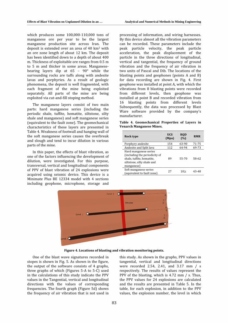
processing of information, and wiring harnesses. By this device almost all the vibration parameters can be recorded. These parameters include the peak particle velocity, the peak particle acceleration, the peak displacement of the particle in the three directions of longitudinal, vertical and tangential, the frequency of ground vibration and the frequency of air vibration in two units of Pascal and Dib. The locations of the blasting points and geophones (points A and B) for data recording are shown in Fig. 4. First geophone was installed at point A, with which the vibrations from 8 blasting points were recorded from different levels, then geophone was installed at point B and recorded vibration from 16 blasting points from different levels Subsequently, the data was processed by Blast Ware software provided by the company's manufacturer.
Table 4. Geomechanical Properties of Layers in Venarch Manganese Mines.
RMR RQD (%)
UCS (Mpa) Rock type
71-75 63-90 154 Porphyry andesite
69-73 64-94 112 Andesite and Split lava
58-62 55-70 89
Hard manganese series (including the periodicity of shale, tuffite, hematite, siltstone, silty shale and manganese)
43-48 10 27 Soft manganese series (equivalent to fault zone)
Figure 4. Locations of blasting and vibration monitoring points.
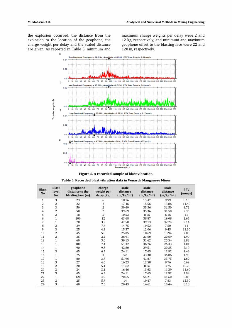
One of the blast wave signatures recorded in stopes is shown in Fig. 5. As shown in the figure, the output of the software consists of 4 graphs, three graphs of which (Figures 5-A to 5-C) used in the calculations of this study indicate the PPV values in the Tangential, vertical and longitudinal directions with the values of corresponding frequencies. The fourth graph (Figure 5d) shows the frequency of air vibration that is not used in
this study. As shown in the graphs, PPV values in tangential, vertical and longitudinal directions were recorded 2.54, 2.41, and 3.17 mm / s respectively. The results of values represent the PPV of the blasting, which is 4.72 mm / s. Thus, the PPV values for 24 explosions are calculated and the results are presented in Table 5. In the table, for each explosion, in addition to the PPV values, the explosion number, the level in which
M. Mohseni et al. Analytical and Numerical Methods in Mining Engineering
84
the explosion occurred, the distance from the explosion to the location of the geophone, the charge weight per delay and the scaled distance are given. As reported in Table 5, minimum and
maximum charge weights per delay were 2 and 12 kg, respectively, and minimum and maximum geophone offset to the blasting face were 22 and 120 m, respectively.
Figure 5. A recorded sample of blast vibration.
Table 5. Recorded blast vibration data in Venarch Manganese Mines
Blast No
Blast level
No
geophone distance to the
blasting face (m)
charge weight per delay (kg)
scale distance
(m/kg^1/3)
scale distance
(m/kg^1/2)
scale distance
(m/kg^2/3)
PPV (mm/s)
1 3 23 6 18.16 13.47 9.99 8.13
2 2 22 2 17.46 15.56 13.86 11.40 3 3 50 2 39.69 35.36 31.50 4.72 4 2 50 2 39.69 35.36 31.50 2.35 5 2 18 5 10.53 8.05 6.16 15 6 1 100 12 43.68 38.87 19.08 1.65 7 1 70 3.2 47.50 39.13 32.24 2.14 8 2 29 7.6 14.75 10.52 7.50 11 9 3 25 4.3 15.37 12.06 9.45 11.30
10 2 45 5.8 25.05 18.69 13.94 7.83 11 2 35 2.2 26.91 23.60 20.69 1.90 12 1 60 3.6 39.15 31.62 25.54 2.83 13 1 100 7.4 51.32 36.76 26.33 1.01 14 1 90 9.3 42.80 29.51 20.35 2.10 15 3 45 6.5 24.11 17.65 12.92 4.46 16 1 75 3 52 43.30 36.06 1.95 17 1 80 3.7 51.96 41.87 33.75 1.60 18 3 27 4.6 16.23 12.58 9.76 6.69 19 2 20 5.1 11.62 8.86 3.75 10.20 20 2 24 3.1 16.46 13.63 11.29 11.60 21 3 45 6.5 24.11 17.65 12.92 7.98 22 1 120 4.9 70.65 54.21 41.60 0.83 23 2 25 5.7 14 10.47 7.83 12.50 24 3 40 7.5 20.43 14.61 10.44 8.18

Effects of Blast Vibration on Unplanned Dilution in an … Analytical and Numerical Methods in Mining Engineering
85
In order to determine the scale distance, one-third power of charge weight per delay, Q1/3, one-second power of charge weight per delay, Q1/2, and two-thirds power of charge weight per delay, Q2/3, were calculated and their coefficients of correlation with PPV were compared. Figs. 6 and 7 demonstrate plots of PPV versus charge weight per delay and distance, respectively.
Figure 6. Plot of recorded PPV versus charge weight per delay
In order to determine an equation for PPV, measured PPVs were investigated against scaled distances (with the mentioned powers of charge weight per delay) and PPV equations were developed with their correlation coefficients determined according to Table 6. Then, in order to determine accuracy of the obtained
relationships, predicted and measured values of PPV were compared and Root-Mean-Square Error (RMSE), Mean Absolute Percentage Error (MAPE), and Variance Accounted For (VAF) of them were calculated using Equations 7 to 9. The calculation results are summarized in Table 6.
Figure 7. Plot of recorded PPV versus distance
(7) √
∑
(8)
∑|
|
(9) [
]
Table 6. Results of data analyzing
Power of charge weight per delay Equation R2 RMSE MAPE VAF
Q1/3 0.8634 1.9636 0.2640 79.6310 Q1/2 0.8282 2.0499 0.3065 77.9106 Q2/3 0.7645 2.1740 0.3582 75.5133
As can be seen from Table 6, the most accurate equation for predicting PPV was obtained from the one-third power of charge weight per delay, Q1/3. Then, Equation 10 is proposed as the general predicted relationship for PPV. Fig. 8 shows the graph of PPV versus scaled distance. The relationship between measured values and predicted values (by Equation 10) of PPV is presented in Fig. 9.
(10)
Figure 8. Plot of recorded PPV versus scaled distance.
0
2
4
6
8
10
12
14
16
0 5 10 15
PP
V(m
m/s
)
Q (kg)
0
5
10
15
20
0 50 100 150
PP
V (
mm
/s)
D (m)
R² = 0.8634
0
5
10
15
20
0 20 40 60 80
PP
V (
mm
/s)
SD (m/kg^1/3)
M. Mohseni et al. Analytical and Numerical Methods in Mining Engineering
86
Figure 9. Relationship between measured and predicted PPVs.
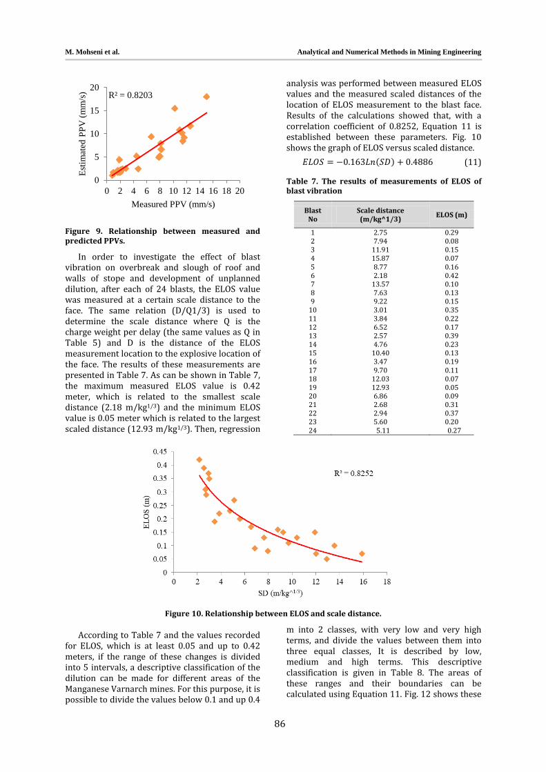
In order to investigate the effect of blast vibration on overbreak and slough of roof and walls of stope and development of unplanned dilution, after each of 24 blasts, the ELOS value was measured at a certain scale distance to the face. The same relation (D/Q1/3) is used to determine the scale distance where Q is the charge weight per delay (the same values as Q in Table 5) and D is the distance of the ELOS measurement location to the explosive location of the face. The results of these measurements are presented in Table 7. As can be shown in Table 7, the maximum measured ELOS value is 0.42 meter, which is related to the smallest scale distance (2.18 m/kg1/3) and the minimum ELOS value is 0.05 meter which is related to the largest scaled distance (12.93 m/kg1/3). Then, regression
analysis was performed between measured ELOS values and the measured scaled distances of the location of ELOS measurement to the blast face. Results of the calculations showed that, with a correlation coefficient of 0.8252, Equation 11 is established between these parameters. Fig. 10 shows the graph of ELOS versus scaled distance.
(11)
Table 7. The results of measurements of ELOS of blast vibration
Blast No
Scale distance (m/kg^1/3)
ELOS (m)
1 2.75 0.29 2 7.94 0.08 3 11.91 0.15 4 15.87 0.07 5 8.77 0.16 6 2.18 0.42 7 13.57 0.10 8 7.63 0.13 9 9.22 0.15
10 3.01 0.35 11 3.84 0.22 12 6.52 0.17 13 2.57 0.39 14 4.76 0.23 15 10.40 0.13 16 3.47 0.19 17 9.70 0.11 18 12.03 0.07 19 12.93 0.05 20 6.86 0.09 21 2.68 0.31 22 2.94 0.37 23 5.60 0.20 24 5.11 0.27
Figure 10. Relationship between ELOS and scale distance.
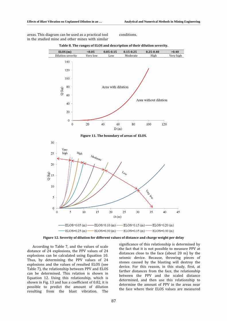
According to Table 7 and the values recorded for ELOS, which is at least 0.05 and up to 0.42 meters, if the range of these changes is divided into 5 intervals, a descriptive classification of the dilution can be made for different areas of the Manganese Varnarch mines. For this purpose, it is possible to divide the values below 0.1 and up 0.4
m into 2 classes, with very low and very high terms, and divide the values between them into three equal classes, It is described by low, medium and high terms. This descriptive classification is given in Table 8. The areas of these ranges and their boundaries can be calculated using Equation 11. Fig. 12 shows these
R² = 0.8203
0
5
10
15
20
0 2 4 6 8 10 12 14 16 18 20
Est
imat
ed P
PV
(m
m/s
)
Measured PPV (mm/s)
Effects of Blast Vibration on Unplanned Dilution in an … Analytical and Numerical Methods in Mining Engineering
87
areas. This diagram can be used as a practical tool in the studied mine and other mines with similar
conditions.
Table 8. The ranges of ELOS and description of their dilution severity.
ELOS (m) >0.05 0.05-0.15 0.15-0.25 0.25-0.40 < 0.40 Dilution severity Very low Low Moderate High Very high
Figure 11. The boundary of areas of ELOS.
Figure 12. Severity of dilution for different values of distance and charge weight per delay
According to Table 7, and the values of scale distance of 24 explosions, the PPV values of 24 explosions can be calculated using Equation 10. Thus, by determining the PPV values of 24 explosions and the values of resulted ELOS (see Table 7), the relationship between PPV and ELOS can be determined. This relation is shown in Equation 12. Using this relationship, which is shown in Fig. 13 and has a coefficient of 0.82, it is possible to predict the amount of dilution resulting from the blast vibration. The
significance of this relationship is determined by the fact that it is not possible to measure PPV at distances close to the face (about 20 m) by the seismic device. Because, throwing pieces of stones caused by the blasting will destroy the device. For this reason, in this study, first, at farther distances from the face, the relationship between the PPV and the scaled distance determined, and then use this relationship to determine the amount of PPV in the areas near the face where their ELOS values are measured

M. Mohseni et al. Analytical and Numerical Methods in Mining Engineering
88
and, incidentally, these areas have the highest amount of dilution. In Equation 12, if the PPV value be 6.73 mm / s, the ELOS value will be zero. Therefore, the minimum PPV value required for occurring the dilution, is greater than 6.73 mm/s. obviously, in an amount less than 6.6 mm / s, the
dilution does not occur because the ELOS value cannot be negative.
(12)
Figure 13. Relationship between PPV and ELOS.
5. CONCLUSIONS
In this paper, the damage caused by blast vibration on the walls and roof of underground mining stopes resulting in unplanned dilution were investigated. An empirical equation was obtained for predicting peak particle velocity (PPV) from the one-third power of charge weight per delay, Q1/3, with acceptable accuracy. The relationship between distance to face and charge weight per delay was determined for different dilutions and the unplanned dilution areas in stopes were acceptably predicted based on these parameters using a practical diagram. Also, the relationship between ELOS and PPV was determined and found in order to create dilution; the value of PPV should be greater than 6.73 mm/s.
REFERENCES
[1] Stewart, P., & Trueman, R., Strategies for minimising and predicting dilution in narrow-vein mines–NVD Method. Paper presented at the Narrow Vein Mining Conference, 2008.
[2] Henning, J. G., & Mitri, H. S., Numerical modelling of ore dilution in blast-hole stoping. International Journal of Rock Mechanics and Mining Sciences, 2007. 44(5): 692-703.
[3] Saeedi, G., Rezai, B., Shareiar, K., & Oraee, K., Quantifying level of out-of-seam dilution for longwall mining method and its impact on yield of coal washing plant in Tabas coal mine. Paper presented at the Proceedings of the international seminar on mineral processing technology, Trivandrum, India, 2008.
[4] Saeedi, G., Shahriar, K., Rezai, B., & Karpuz ,C., Numerical modelling of out-of-seam dilution in longwall retreat mining. International Journal of Rock Mechanics and Mining Sciences, 2010. 47(4): 533-543.
[5] Najafi, A. B., Saeedi, G. R., & Farsangi, M. A. E., Risk analysis and prediction of out-of-seam dilution in longwall mining. International Journal of Rock Mechanics and Mining Sciences, 2014. 70:115-122.
[6] Bahri, N. A., Ebrahimi, F. M. A., & Reza, S. G., A fuzzy logic model to predict the out-of-seam dilution in longwall mining. International Journal of Mining Science and Technology, 2015. 25(1): 91-98 .
[7] Ataei, M., Underground mining, Shahrood University of Technology, 2015. Vol 3: 713-1042, (In Pesian)
[8] Mathews, K., Hoek, E., Wyllie, D.C., & Steward, SBV., Prediction of stable excavation spans for mining at depths below 1000 Meters in hard rock mines. CANMET Report DSS Serial, 1981. No. 0SQ80-00, 81.
Effects of Blast Vibration on Unplanned Dilution in an … Analytical and Numerical Methods in Mining Engineering
89
[9] Potvin, Y., Empirical open stope design in Canada, Ph.D thesis, University of British Columbia, 1988.
[10] Mawdesley, C., Trueman, R., & Whiten, W., Extending the Mathews stability graph for open–stope design, Mining Technology, 2001. 110(1): 27-39.
[11] Scoble, M., & Moss, A., Dilution in underground bulk mining: implications for production management, Geological Society, London, Special Publications, 1994. 79(1): 95-108.
[12] Nickson, S.D., Cable support guidelines for underground hard rock mine operations, Ph.D thesis, University of British Columbia, 1992.
[13] Hadjigeorgiou, J., Leclair, J., & Potvin, Y., An update of the stability graph method for open stope design, CIM Rock Mechanics and Strata Control session, Halifax, Nova Scotia, 1995. 14-18.
[14] Clark, L., & Pakalnis, R., An empirical design approach for estimating unplanned dilution from open stope hangingwalls and footwalls. Paper presented at the Presentation at 99th Canadian Institute of Mining annual conference, Vancouver, BC, 1997.
[15] Mine, R., Empireical stope design, PhD thesis, University of British Columbia, 1986.
[16] Clark, L.M., Minimizing dilution in open stope mining with a focus on stope design and narrow vein long-hole blasting, PhD thesis, University of British Columbia, 1998.
[17] Wang, J., Milne, D., Yao, M., & Allen, G., Factors influencing open stope dilution at Hudson Bay Mining and Smelting, 5th North American Rock Mechanics Symposium, Toronto, Canada, 2002.
[18] Annels, A.E., Mineral deposit evaluation: A practical approach, Springer Science & Business Media, 2012.
[19] Singh, P., Roy, M., Paswan, R. K., Dubey, R., & Drebenstedt, C., Blast vibration effects in an underground mine caused by open-pit mining. International Journal of Rock Mechanics and Mining Sciences, 2015. 80: 79-88.
[20] Jha, A. K., & Deb, D., Estimation of Damage in an Underground Mine Due to Effect of Surface Blasting. Journal of Geological Resource and Engineering, 2015. 4: 203-212.
[21] Suorineni, F., Tannant, D., & Kaiser, P., Determination of fault-related sloughage in open stopes, International Journal of Rock Mechanics and Mining Sciences, 1999. 36(7): 891-906.
[22] Wang, J., Influence of stress, undercutting, blasting and time on open stope stability and dilution, Ph.D thesis, University of Saskatchewan Saskatoon, 2004.
[23] Jang, H., Topal, E., & Kawamura, Y., Decision support system of unplanned dilution and ore-loss in underground stoping operations using a neuro-fuzzy system. Applied Soft Computing, 2015. 32:1-12.
[24] Popov, G. N., The working of mineral deposits: Mir Publishers, 1971.
[25] Agoškov, M. I., Borisov, S. S., & Bojarskij, V. A. e., Mining of ores and non-metalic minerals: Mir, 1988.
[26] Henning, J. G., Evaluation of long-hole mine design influences on unplanned ore dilution: Ph.D thesis, Mc Gill University, 2007.
[27] Miller, F., Potvin, Y., & Jacob, D., Laser measurement of open stope dilution. CIM (Canadian Mining and Metallurgical) Bulletin, 1992. 85(962): 96-102.
[28] Miller, F., & Jacob, D., Cavity monitoring system: Google Patents, 1993.
[29] Mah, S., Pakalnis, R., Poulin, R., & Clark, L., Obtaining quality cavity monitoring survey data. Proceedings of the CAMI, 1995. 95, 3rd.
[30] Germain, P., Hadjigeorgiou, J., & Lessard, J., On the relationship between stability prediction and observed stope overbreak. Rock Mechanics, Aubertin, Hassani and Mitri (eds), 1996. 277-283.
[31] Yao, X., Allen, G., & Willett, M., Dilution evaluation using Cavity Monitoring System at HBMS—Trout Lake Mine. Paper presented at the Proceeding of the 101st CIM annual general meeting, Calgary, 1999.
[32] Calvert, T., Simpson, J., & Sandy, M., Open stope design at Normandy Golden Grove Operations. Proceedings of MassMin, 2000. 653-659.
[33] Uggalla, S., Sublevel open sloping- design and planning at the Olympic Dam Mine. Underground Mining Methods: Engineering Fundamentals and International Case Studies. Society of Mining, Metallurgy and Exploration, 8307 Shaffer Parkway, Littleton, CO 80127, USA, 2001., 239-244.
[34] Ran, J., Hangingwall sloughing mechanism in open stope mining. CIM bulletin, 2002. 95(1064): 74-77.

M. Mohseni et al. Analytical and Numerical Methods in Mining Engineering
90
[35] SOYER, N., AN APPROACH ON DILUTION AND ORE RECOVERY/LOSS CALCULATIONS IN MINERAL RESERVE ESTIMATIONS AT THE CAYELI MINE, TURKEY. Citeseer, 2006.
[36] Luo, Z.-q., Liu, X.-m., Zhang, B., Lu, H., & Li, C., Cavity 3D modeling and correlative techniques based on cavity monitoring. Journal of central south university of technology, 2008. 15(5): 639-644.
[37] El Mouhabbis, H. Z., Effect of stope construction parameters on ore dilution in narrow vein mining, 2013.
[38] Hossaini, S., & Sen, G., Effect of explosive type on particle velocity criteria in ground vibration. Journal of Explosives Engineering, 2004. 21(4):34-36.
[39] Langefors, U., & Kihlström, B., The modern technique of rock blasting: Wiley, 1978.
[40] Oriard, L., Blasting effects and their control. Underground Mining Methods Handbook, 1982. 1590-1603.
[41] Andrieux, P., Drolet, A., McKenzie, C., & Heilig, J., The impact of blasting on excavation design--A geomechanics approach. (No. CONF-9401127--). International Society of Explosives Engineers, Cleveland, OH (United States), 1994.
[42] Yu, T., The development of new blast damage criteria for blast-hole mining operations. Report prepared by Falconbridge Ltd., Kidd Creek Division, CANMET Project (1-9050), 152, 1993.
[43] Yu, T., & Vongpaisal, S., New blast damage criteria for underground blasting. CIM bulletin, 1996. 89(998):139-145.
[44] Tunstall, A., Damage to underground excavations from open-pit blasting. Transactions of the Institution of Mining and Metallurgy Section A-Mining Industry, 1997. 106, A19-A24.
[45] Adhikari, G., Babu, A. R., Balachander, R., & Gupta, R., On the application of rock mass quality for blasting in large underground chambers. Tunnelling and Underground Space Technology, 1999. 14(3): 367-375.
[46] Singh, P., Blast vibration damage to underground coal mines from adjacent open-pit blasting. International Journal of Rock Mechanics and Mining Sciences, 2002. 39(8): 959-973.
[47] Singh, P., & Roy, M., Damage to surface structures due to blast vibration. International Journal of Rock Mechanics and Mining Sciences. 2010. 47(6): 949-961.
[48] Xia, X., Li, H., Li, J., Liu, B., & Yu, C., A case study on rock damage prediction and control method for underground tunnels subjected to adjacent excavation blasting. Tunnelling and Underground Space Technology, 2013. 35: 1-7.
[49] Roy, M., Singh, P., Sarim, M., & Shekhawat, L., Blast design and vibration control at an underground metal mine for the safety of surface structures. International Journal of Rock Mechanics and Mining Sciences, 2016. 83: 107-115.
Related Documents