University of Tennessee, Knoxville University of Tennessee, Knoxville TRACE: Tennessee Research and Creative TRACE: Tennessee Research and Creative Exchange Exchange Masters Theses Graduate School 5-2005 Long Range Interdiction: Effects Based Justification of the B-1B Long Range Interdiction: Effects Based Justification of the B-1B Lancer Aircraft Lancer Aircraft Stanley Clay Jones University of Tennessee - Knoxville Follow this and additional works at: https://trace.tennessee.edu/utk_gradthes Part of the Aerospace Engineering Commons Recommended Citation Recommended Citation Jones, Stanley Clay, "Long Range Interdiction: Effects Based Justification of the B-1B Lancer Aircraft. " Master's Thesis, University of Tennessee, 2005. https://trace.tennessee.edu/utk_gradthes/2088 This Thesis is brought to you for free and open access by the Graduate School at TRACE: Tennessee Research and Creative Exchange. It has been accepted for inclusion in Masters Theses by an authorized administrator of TRACE: Tennessee Research and Creative Exchange. For more information, please contact [email protected].

Welcome message from author
This document is posted to help you gain knowledge. Please leave a comment to let me know what you think about it! Share it to your friends and learn new things together.
Transcript
University of Tennessee, Knoxville University of Tennessee, Knoxville
TRACE: Tennessee Research and Creative TRACE: Tennessee Research and Creative
Exchange Exchange
Masters Theses Graduate School
5-2005
Long Range Interdiction: Effects Based Justification of the B-1B Long Range Interdiction: Effects Based Justification of the B-1B
Lancer Aircraft Lancer Aircraft
Stanley Clay Jones University of Tennessee - Knoxville
Follow this and additional works at: https://trace.tennessee.edu/utk_gradthes
Part of the Aerospace Engineering Commons
Recommended Citation Recommended Citation Jones, Stanley Clay, "Long Range Interdiction: Effects Based Justification of the B-1B Lancer Aircraft. " Master's Thesis, University of Tennessee, 2005. https://trace.tennessee.edu/utk_gradthes/2088
This Thesis is brought to you for free and open access by the Graduate School at TRACE: Tennessee Research and Creative Exchange. It has been accepted for inclusion in Masters Theses by an authorized administrator of TRACE: Tennessee Research and Creative Exchange. For more information, please contact [email protected].

To the Graduate Council:
I am submitting herewith a thesis written by Stanley Clay Jones entitled "Long Range
Interdiction: Effects Based Justification of the B-1B Lancer Aircraft." I have examined the final
electronic copy of this thesis for form and content and recommend that it be accepted in partial
fulfillment of the requirements for the degree of Master of Science, with a major in Aviation
Systems.
Robert B. Richards, Major Professor
We have read this thesis and recommend its acceptance:
Frank G. Collins, Charles T. N. Paludan
Accepted for the Council:
Carolyn R. Hodges
Vice Provost and Dean of the Graduate School
(Original signatures are on file with official student records.)

To the Graduate Council: I am submitting herewith a thesis written by Stanley Clay Jones entitled “Long Range Interdiction: Effects Based Justification of the B-1B Lancer Aircraft.” I have examined the final electronic copy of this thesis for form and content and recommend that it be accepted in partial fulfillment of the requirements for the degree of Master of Science, with a major in Aviation Systems. Robert B. Richards Major Professor We have read this thesis and recommend its acceptance: Frank G. Collins Charles T. N. Paludan Accepted for the Council: Anne Mayhew Vice Chancellor and Dean of Graduate Studies
(Original signatures on file with official student records)
LONG RANGE INTERDICTION: EFFECTS BASED JUSTIFICATION OF THE B-1B LANCER AIRCRAFT
A Thesis Presented for the Master of Science Degree
The University of Tennessee, Knoxville
Stanley Clay Jones
May 2005
ii
Dedication
This thesis is dedicated to my father, James Clarence Jones, for giving me
every opportunity to succeed, for never questioning my ability, and supporting me
in every endeavor that I’ve ever undertaken. It is also dedicated to my wife Gina,
and my daughters Kennedy, Morgan, and Sydney for always having faith in me
and for never wavering during my extended deployments in defense of our
nation.

iii
Acknowledgements
I wish to thank all those who have helped me complete my Master of
Science in Aviation Systems. I would especially like to thank the staff of the U.S.
Naval Test Pilot School and the University of Tennessee Space Institute, both for
providing superb instruction and guidance during my studies. I would like to add
a special thanks to Dr. Bob Richards for his personal time and expert advice,
which allowed me to complete this degree.
iv
Abstract
The purpose of this study was to evaluate the B-1B aircraft for the land-
based, long-range, ground attack mission and to use that evaluation to support
my belief that the B-1B aircraft provides a better platform than U.S. Naval fighter
aircraft for the same, based on the effects that each aircraft delivers.
One flight totaling 6.5 hours was flown by the author in the B-1B aircraft
during daylight visual meteorological conditions (VMC) and included low level
flight, aerial refueling, low altitude weapons delivery, threat simulation at an
Electronic warfare range, and terminal area operations. This flight was used to
evaluate the B-1B aircraft in a test environment and concentrated mainly on
aircraft flying qualities. Additionally, thirty-three F/A-18 flights were flown by the
author during actual combat operations from the flight deck of the USS John C.
Stennis, in support of actual combat operations in Afghanistan during Operation
Enduring Freedom. The contrast in effects based capabilities between the F/A-
18 and the B-1B form the basis of this thesis.
While the U.S. Navy’s approach to long range interdiction was
revolutionary, compared to how the U.S. Navy traditionally conducts flight
operations, it was lacking in the effectiveness afforded through the use of the B-
1B aircraft, primarily due to the B-1B’s superior range, endurance, and payload.
Quantitative and qualitative findings regarding the flying qualities, weapons
systems, and overall aircraft performance of the B-1B support the continued

v
development of the B-1B aircraft and its inclusion as a critical weapons platform
in future conflict planning and execution.
vi
Preface
A portion of the data contained within this thesis was obtained during an
academic exercise by the author when he was a student at the United States
Naval Test Pilot School. The results, conclusions, and recommendations are the
opinion of the author and are not the official position of the United States Navy,
the United States Department of Defense, the Naval Air Systems Command,
Naval Air Warfare Center, or the Boeing Company. The use of trade names
within this thesis does not constitute an official endorsement.

Table of Contents
Chapter Page
vii
1 Operation Enduring Freedom and the F/A-18 ............................................... 1
1.1 Background ............................................................................................ 1
1.2 The Typical F/A-18 Flight ....................................................................... 3
1.3 F/A-18 Effects ........................................................................................ 5
2 The B-1B Bomber.......................................................................................... 8
2.1 History .................................................................................................... 8
2.2 Aircraft Description................................................................................. 8
2.3 B-1B Handling Qualities ....................................................................... 12
2.3.1 Overview ....................................................................................... 12
2.3.2 Ground Handling Qualities ............................................................ 12
2.3.2.1 Nose Wheel Steering................................................................. 12
2.3.3 Flying Qualities and Performance ................................................. 13
2.3.3.1 Takeoff ...................................................................................... 13
2.3.3.2 Airways Navigation .................................................................... 15
2.3.3.3 Combat Range .......................................................................... 18
2.3.3.4 Combat Endurance.................................................................... 19
2.3.3.5 Aerial Refueling ......................................................................... 19
2.3.3.6 Level Turns................................................................................ 21
2.3.3.7 Landing...................................................................................... 27
2.4 B-1B JDAM Capabilities ....................................................................... 30
3 Operation Enduring Freedom and the B-1B ................................................ 34
Table of Contents
Chapter Page
viii
4 Summary ..................................................................................................... 35
5 Conclusions and Recommendations ........................................................... 36
List of References............................................................................................... 40
Vita ..................................................................................................................... 42

List of Tables
Table Page
ix
Table 2-1. B-1B Takeoff Configuration Changes............................................... 14
Table 2-2. B-1B Long Period Characteristics .................................................... 17
Table 2-3. B-1B Mission Profile ......................................................................... 18
Table 2-4. B-1B Landing Configuration Changes .............................................. 28
List of Figures
Figures Page
x
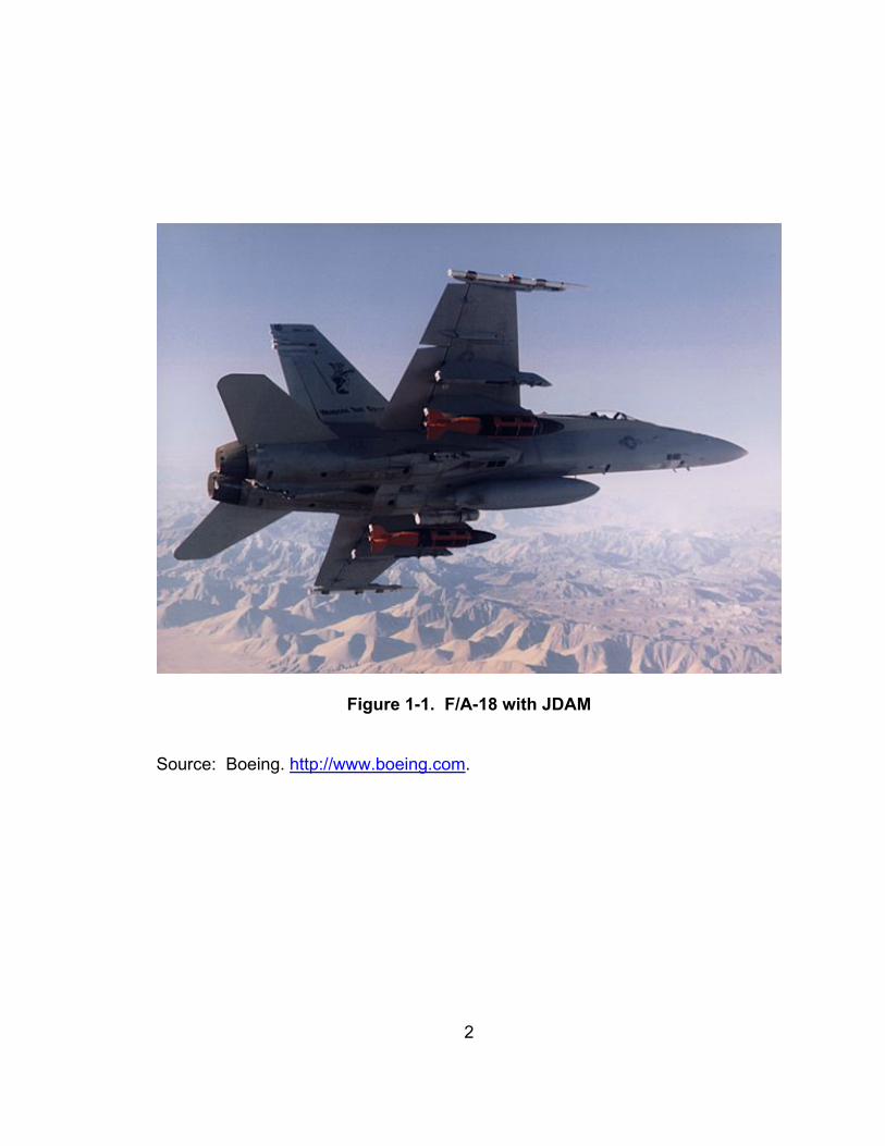
Figure 1-1. F/A-18 with JDAM ............................................................................. 2
Figure 2-1. B-1B Three View ............................................................................... 9
Figure 2-2. B-1B Phugoid .................................................................................. 17
Figure 2-3. B-1B Longitudinal Stick Force Gradient for Deflection .................... 23
Figure 2-4. B-1B Stick Force Gradient for Normal Acceleration ........................ 24
Figure 2-5. B-1B Roll Sensitivity ........................................................................ 26
Figure 2-6. B-1B JDAM Delivery at China Lake Test Range ............................. 31
Figure 2-7. JDAM Schematic............................................................................. 33
1
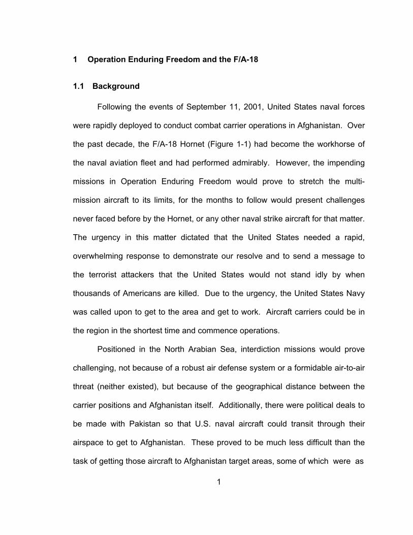
1 Operation Enduring Freedom and the F/A-18
1.1 Background Following the events of September 11, 2001, United States naval forces
were rapidly deployed to conduct combat carrier operations in Afghanistan. Over
the past decade, the F/A-18 Hornet (Figure 1-1) had become the workhorse of
the naval aviation fleet and had performed admirably. However, the impending
missions in Operation Enduring Freedom would prove to stretch the multi-
mission aircraft to its limits, for the months to follow would present challenges
never faced before by the Hornet, or any other naval strike aircraft for that matter.
The urgency in this matter dictated that the United States needed a rapid,
overwhelming response to demonstrate our resolve and to send a message to
the terrorist attackers that the United States would not stand idly by when
thousands of Americans are killed. Due to the urgency, the United States Navy
was called upon to get to the area and get to work. Aircraft carriers could be in
the region in the shortest time and commence operations.
Positioned in the North Arabian Sea, interdiction missions would prove
challenging, not because of a robust air defense system or a formidable air-to-air
threat (neither existed), but because of the geographical distance between the
carrier positions and Afghanistan itself. Additionally, there were political deals to
be made with Pakistan so that U.S. naval aircraft could transit through their
airspace to get to Afghanistan. These proved to be much less difficult than the
task of getting those aircraft to Afghanistan target areas, some of which were as
2
Figure 1-1. F/A-18 with JDAM
Source: Boeing. http://www.boeing.com.
3
much as a thousand miles away, with sufficient fuel to remain on station long
enough to prosecute targets, provide close air support for ground troops, conduct
surveillance operations, and safely return to the carrier. In wars past, U.S.
carriers typically operated directly off shore from the area of operations. In
Vietnam, conducting missions over a range of only one hundred miles was
considered difficult.
1.2 The Typical F/A-18 Flight It was determined early on that in order to carry out such missions, there
would be a heavy reliance of tanker aircraft for in-flight refueling. These aircraft
were provided by the United States Air Force. The KC-10 Extender and KC-135
Stratotanker aircraft could carry sufficient fuel and possessed the range and
endurance required to provide continuous tanking for the Navy while operating
from various bases throughout the region, bases that were too far away for
fighter aircraft to operate from.
The typical Hornet mission, from the deck of a U.S. carrier, would differ
from any missions of the past. Navy pilots and planners, in coordination with the
Joint Forces Air Component Commander, were forced to change their mindset in
determining how to plan and carry out missions that would take them over a
thousand miles during missions lasting typically between six and eight hours.
This was in stark contrast to the traditional two to three hour missions flown
during Operation Desert Storm, which then were thought to be stretching the
envelope of capability.
4
Typically, the Navy employed the Hornet in sections (flights of two
aircraft), one of which was dedicated the flight lead and had overall responsibility
for the flight and the other the wingman. After launching from the carrier, these
aircraft met at a predetermined rendezvous point somewhere near the carrier,
and proceeded together north into Afghanistan. The first hurdle was locating the
organic (carrier based) Navy tanker, usually a S-3 Viking, and taking on enough
fuel to top off, usually approximately three thousand pounds each. With a full
tank of gas, the section then proceed further north, passing into Pakistan in
search of the next required tanker, this time a U.S. Air Force KC-10 or KC-135. It
wasn’t unusual for Hornets to arrive at the predetermine tanking location, only to
find that clouds would force them to conduct aerial refueling at much higher
altitudes than desired or while in the clouds, a feat not practiced in typical training
missions. If forced to higher altitudes, this made the task of tanking even that
much more difficult due to the thinner air, reduced thrust response of the Hornet
engines, and increased angle of attack encountered when adhering to tanking
indicated airspeed limits. Once complete, with yet another full tank of gas, the
section of Hornets proceeded even further north to conduct their mission, often
times conducting aerial refueling two or three more times before heading south to
return to the carrier. All in all, the typical aerial refueling evolution would result in
each aircraft taking on six to eight thousand pounds of fuel, ensuring that each
had enough for the aircraft to at least get out of Afghanistan and to land in a
remote, isolated, barely suitable airfield in Pakistan, in the event of an emergency
that would preclude them from returning to the carrier. When all was said and
5
done, on an average flight, the Hornets received approximately 35,000 pounds of
fuel from airborne tankers and were able to dedicate only 30-40 minutes to the
actual mission of putting bombs on target.
Making the missions even more difficult, half were flown at night while
wearing night vision devices (NVDs). The insidious effects of wearing NVDs,
which can include spatial disorientation, degraded depth perception, and fatigue
to both the neck muscles and eyes of the aviator added to the complexity of the
already daunting task of flying an extended mission, over hostile territory, while
carrying out high risk, stressful evolutions such as night aerial refueling and
delivering ordnance. Lastly, once back at the carrier, the pilots of these aircraft
still had to land their aircraft, perhaps the most difficult, routinely conducted task
in all of aviation. Though the opportunities for a mishap were abundant, not a
single Hornet was lost.
1.3 F/A-18 Effects
Due to fuel requirements, the F/A-18s were forced to carry two additional
drop tanks, leaving only two wing stations on which to carry air-to-ground
ordnance. In the early stages of the conflict, multiple bomb types were carried, to
include laser guided munitions, “dumb” bombs, and Global Positioning System
(GPS) guided smart weapons such as Joint Direct Attack Munitions (JDAM).
While all of these proved effective in destroying most of, if not all of, the easy to
locate command and control (C2), radar sites, buildings and runways, it was
soon realized that in order to maximize the effects of the Hornets, precision
6
weapons were required to strike the most difficult of targets. This was primarily
due to inclement weather, which served to obscure the target area. The JDAM
became the weapon of choice due to its GPS guidance, ease of delivery, which
did not require visual acquisition of targets, and reliability such that it could be
expended in and through the weather due to its superior accuracy. JDAM is truly
a drop and leave weapon. Additionally, the JDAM did not require the aircraft to
descend to lower altitude and expend greater amounts of fuel or put themselves
closer to the threat. Given the proper interface for programming the weapons
(target coordinates, etc), the accuracy of JDAM munitions is not dependent on
the platform by which they are dropped. This capability negates the possible
negative effects of inertial drift, over extended flights that could otherwise affect
the accuracy of ordnance delivery. The JDAM contains its own guidance system
so that once properly programmed, it need only be released at the proper
parameters to achieve the desired affects. Listing specific information on those
parameters would classify this report, but it can be said that there is little difficulty
in achieving them. The JDAM weapons met all expectations for accuracy and
desired effects. With that said, the Hornet interdiction missions were as
successful as they could possibly be.
While overcoming major obstacles to success, the net result was that in
conducting six to eight hour missions, while working through all of the inherent
difficulties already discussed, each aircraft could drop only two bombs and with
the limited number of aircraft aboard an aircraft carrier, the use of overwhelming
force would be conducted in the manner of a marathon rather than a sprint. This

7
proved to be decisive, but not rapid. In all, U.S. Navy aircraft flew 75% of the
sorties flown in support of Operation Enduring Freedom between 7 October 2001
and 23 December 2001, delivering less than 30% of the total weapons.
8
2 The B-1B Bomber
2.1 History The first B-1A, produced by Rockwell International, now Boeing Defense
And Space Group, was developed in 1974. Its prime mission was to replace the
aging B-52 Stratofortress, though the initial conception was that of a nuclear
bomber. However, prior to going into production, the program was cancelled,
though flight testing continued. The B-1B, an improved variant, was approved in
1981. This variant included a vastly increased payload over the B-1A variant, as
well as a significant reduction in radar cross section and improved avionics.
The B-1B was first used in combat in 1988 during Operation Desert Fox
and has subsequently seen action in Operation Allied Force, Operation Enduring
Freedom, and Operation Iraqi Freedom.
2.2 Aircraft Description The B1-B, depicted in Figure 2-1, is a long range, supersonic bomber
manufactured by Rockwell International and designed for supersonic speed at
altitude and high subsonic speeds at low levels. The aircraft has
accommodations for a pilot, copilot, Offensive Systems Officer (OSO), and
Defensive Systems Officer (DSO) with provisions for an instructor Pilot (IP) and
9
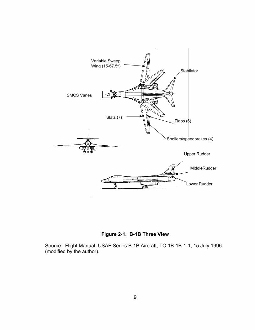
Figure 2-1. B-1B Three View Source: Flight Manual, USAF Series B-1B Aircraft, TO 1B-1B-1-1, 15 July 1996 (modified by the author).
Upper Rudder
MiddleRudder
Lower Rudder
Stabilator
Variable Sweep Wing (15-67.5°)
Flaps (6) Slats (7)
Spoilers/speedbrakes (4)
SMCS Vanes
10
Avionics Instructor (AI). The B-1B aircraft was designed to penetrate highly
defended airspace, attacking targets with conventional weapons and has been
upgraded for precision guided munitions. The aircraft is powered by four General
Electric F101-GE-102 dual rotor, afterburning turbofan engines designed to
produce 15,000 lb of non-afterburning thrust and up to 30,000 lb of thrust with
afterburner. The aircraft design incorporates a blended wing body with variable
sweep wings.
The primary control surfaces consist of a three-section rudder, four spoiler
panels on the upper surface of each wing, and horizontal stabilators. The pitch
attitude of the aircraft is controlled by symmetrical deflection of the horizontal
stabilators. Roll attitude is controlled by asymmetrical deflection of the horizontal
stabilators and by deflection of the spoilers. The aircraft is equipped with a
variable sweep wing which can stopped at any angle between 15 and 67.5
degrees. However, the only wing sweep positions currently cleared for use are
15, 20, 25, 55, and 67.5°.
The secondary flight control system consists of the wing sweep system,
an overwing fairing system designed to accommodate wing sweep and to provide
smooth aerodynamic surfaces at the wing root, leading edge slats, trailing edge
flaps, and lateral control spoilers which also function as speedbrakes. Structural
mode control vanes, designed to reduce structural bending oscillations in the
longitudinal and lateral axes as part of the Structural Mode Control System
(SMCS), are mounted on each side of the forward fuselage. Conventional
control sticks and rudder pedals, mechanically connected between the pilot and
11
copilot seats, provide control inputs to the respective control surface actuators.
Artificial feel is provided in the lateral and longitudinal axes through pitch and roll
bungees. Longitudinal and lateral trim control, through a five-position switch on
each control stick, consists of actuators to position the horizontal stabilators
through the pitch roll mixer. The pitch roll mixer also receives signals from the
Stability Control and Augmentation System (SCAS), which was designed to
provide stability about all axes by transforming signals from pilot inputs and
aircraft motion into flight control surface displacements to produce the desired
damping, maneuver control, and trim. The Automatic Flight Control System
(AFCS) operates through the SCAS and provides several modes of operation,
including Automatic Terrain Following (ATF). The aircraft is equipped with an
electrically controlled and hydraulically operated tricycle landing gear system.
The landing gear system includes nose wheel steering, a damping system, and a
brake control and antiskid system. The aircraft is capable of carrying a wide
assortment of air-to-ground munitions and fuel tanks in three configurable
weapons bays.
The aircraft is equipped with a large avionics suite, including the APQ-164
Offensive Radar System (ORS) multi-mode radar, a SKN-2440 High Accuracy
Inertial Navigation System (HAINS), the ALQ-161 Radio Frequency
Surveillance/Electronic Counter-Measures System (RFS/ECMS), and other
subsystems supporting the Offensive/Defensive Avionics System.
12
2.3 B-1B Handling Qualities
2.3.1 Overview In evaluating the B-1B, flying qualities that were most important to
completing the long range, interdiction mission and could be completed during
the single flight were evaluated. Due to the limited scope of the actual test flight
(only 6.5 hours), not all areas were looked at, however, enough areas were
evaluated to make a determination as to the suitability of the aircraft.
The specific areas evaluated fall into one or more of the following
categories: Longitudinal Flying Qualities (pitch), Lateral Directional Flying
Qualities (roll and yaw), and Ground Handling. Quantitative testing consisted of
classical longitudinal and lateral-directional test techniques routinely used in flight
testing and taught at the US Naval Test Pilot School. Flight test techniques,
described in the Fixed Wing Stability and Control Theory and Flight Test
Techniques Manual and the Fixed Wing Performance Manual, references 1 and
2, were used throughout.
2.3.2 Ground Handling Qualities
2.3.2.1 Nose Wheel Steering
The effectiveness of the nose wheel steering system was evaluated while
taxiing to and from the runway. The purpose was to ensure that the aircraft
would maintain a constant track without over-tasking the pilot. To do so, the
system must not have free play and must be predictably responsive to control
inputs. Starting into and rolling out of turns, while maintaining the aircraft position
13
on the taxiway centerline was easily accomplished through smooth rudder pedal
inputs to steer the aircraft. There was no need for great anticipation, nor was
there any lag or noticeable free play.
2.3.3 Flying Qualities and Performance
2.3.3.1 Takeoff
A consideration in the design of many aircraft is the distance that it takes
to get airborne and the ease at which the pilot can safely achieve a desired pitch
attitude while conducting a takeoff. The typical concern is not to over-rotate, or
put the aircraft in a higher nose up attitude than is desired. This is to preclude
stalling the aircraft or to prevent dragging the rear of the empennage, which
would result in aircraft damage and potentially dangerous flying qualities as a
result of damage. In the case of the B-1B, with its long airframe, this is a valid
concern.
The ability to capture a desired attitude on takeoff was evaluated during a
single takeoff from a dry runway with a 6 knot headwind component and 10 knot
crosswind component. The aircraft weight was 355,000 pounds and was not
loaded with ordnance. It is assumed that similar results would have been
obtained as long as flight manual restrictions for center of gravity and gross
weight were adhered to. The desired pitch attitude on takeoff for the B-1B is 7°
nose up. Using this as a target and selecting full afterburner at the beginning of
the takeoff roll, the aircraft responded smoothly and predictably to an aft stick
deflection of approximately 1 ½ inches, requiring approximately 15 pounds of
14
force. Capturing a 7° nose up attitude was relatively effortless and did not
require any special skill from the pilot.
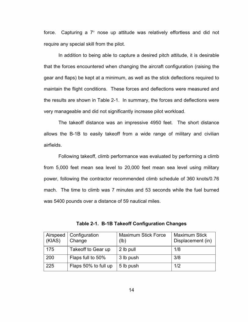
In addition to being able to capture a desired pitch attitude, it is desirable
that the forces encountered when changing the aircraft configuration (raising the
gear and flaps) be kept at a minimum, as well as the stick deflections required to
maintain the flight conditions. These forces and deflections were measured and
the results are shown in Table 2-1. In summary, the forces and deflections were
very manageable and did not significantly increase pilot workload.
The takeoff distance was an impressive 4950 feet. The short distance
allows the B-1B to easily takeoff from a wide range of military and civilian
airfields.
Following takeoff, climb performance was evaluated by performing a climb
from 5,000 feet mean sea level to 20,000 feet mean sea level using military
power, following the contractor recommended climb schedule of 360 knots/0.76
mach. The time to climb was 7 minutes and 53 seconds while the fuel burned
was 5400 pounds over a distance of 59 nautical miles.
Table 2-1. B-1B Takeoff Configuration Changes Airspeed (KIAS)
Configuration Change
Maximum Stick Force (lb)
Maximum Stick Displacement (in)
175 Takeoff to Gear up 2 lb pull 1/8
200 Flaps full to 50% 3 lb push 3/8
225 Flaps 50% to full up 5 lb push 1/2
15
2.3.3.2 Airways Navigation
Once airborne, the B-1B flew nicely. Aircraft control was responsive and
smooth in all axis. For an aircraft to conduct a long range mission, it is desirable
for the pilot to fly with relative ease, that is, to not have to struggle to maintain a
specific parameter such as altitude or airspeed. Over the course of a long flight,
this could result in pilot fatigue or a flight violation from the Federal Aviation
Administration (FAA). In order to determine the ease at which a pilot could
expect to maintain a precise altitude, the aircraft was trimmed for level flight at an
airspeed of 320 knots indicated airspeed. It was difficult to maintain deviations in
altitude of less than 50 feet without paying close attention to the instruments.
Though deviations of 50 feet are certainly acceptable, whether during airways
navigation or expending JDAM ordnance, it was a bit annoying. This minor
problem lead to further investigation of the long period mode (phugoid) of the B-
1B and the documenting of the trim speed band.
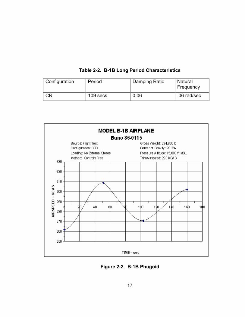
The phugoid is the long term motion of an aircraft after a disturbance and
is a significant factor in trimmed, cruise flight. It is a second order, oscillatory
response and is described by frequency and damping ratio. A representative
range of periods at cruise speeds is 30 seconds to 2 minutes, with damping
ratios of 0.05 to 0.1 [7]. To document the phugoid, an aft longitudinal stick input
is made to the trimmed aircraft to approximately 10 degrees nose up until the
airspeed decreases approximately 20 knots, at which the time the controls are
re-centered. Due to decreased lift at a given angle of attack, the aircraft’s flight
patch will begin to go down, assuming that the aircraft has positive static stability.
16
The aircraft will then accelerate to a speed beyond the speed at which the
maneuver was started until sufficient lift, as a result of the increase in airspeed,
will cause the flight path to go up. Eventually, the aircraft will return to the
original trimmed conditions after a number of iterations. For the B-1, the long
period response was easily excited and lightly damped, the characteristics of
which are shown in Table 2-2 and Figure 2-2. By being easily excited, it doesn’t
take much to get it going, and by being lightly damped, it takes a long time to
settle out.
The trim speed band shows the range of airspeed that an aircraft will
maintain for a given trim setting. Many factors can affect this, including freeplay
in the flight control system and poor flight control centering. The trim speed band
for the B-1B was fairly small in that it was only 5 knots. However, during the
phugoid, the aircraft is trying to return to its original trimmed condition, which in
this case could be plus or minus 5 knots of the original speed, depending on
where that speed lies within the band. If it returns to a speed that is faster than
the start speed of the maneuver, then the aircraft will descend, and if that speed
is slower, it will climb.
The combination of the phugoid characteristics and the trim speed band
are most likely what made it difficult to maintain altitude within 50 feet. However,
the B-1B is equipped with an auto pilot function, which proved to be of great use
and maintained selected flight parameters with great precision. Accordingly, the
minor difficulties in maintaining altitude were nothing more than annoying and
have no effect on mission success.
17
Table 2-2. B-1B Long Period Characteristics
Configuration Period Damping Ratio Natural
Frequency
CR 109 secs 0.06 .06 rad/sec
Figure 2-2. B-1B Phugoid
18
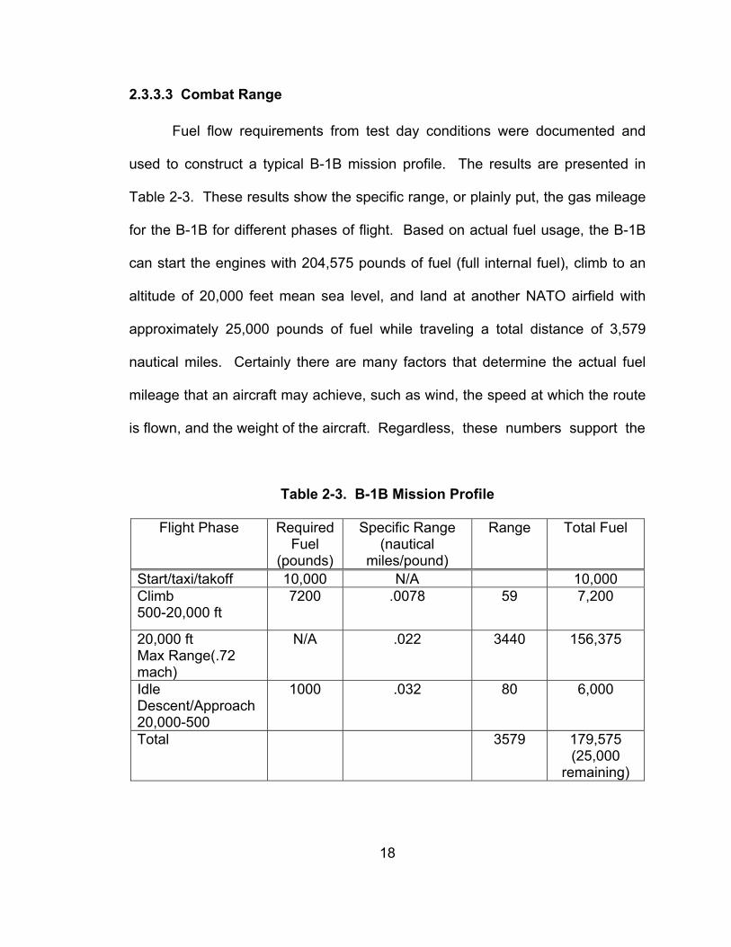
2.3.3.3 Combat Range
Fuel flow requirements from test day conditions were documented and
used to construct a typical B-1B mission profile. The results are presented in
Table 2-3. These results show the specific range, or plainly put, the gas mileage
for the B-1B for different phases of flight. Based on actual fuel usage, the B-1B
can start the engines with 204,575 pounds of fuel (full internal fuel), climb to an
altitude of 20,000 feet mean sea level, and land at another NATO airfield with
approximately 25,000 pounds of fuel while traveling a total distance of 3,579
nautical miles. Certainly there are many factors that determine the actual fuel
mileage that an aircraft may achieve, such as wind, the speed at which the route
is flown, and the weight of the aircraft. Regardless, these numbers support the
Table 2-3. B-1B Mission Profile
Flight Phase Required Fuel
(pounds)
Specific Range (nautical
miles/pound)
Range Total Fuel
Start/taxi/takoff 10,000 N/A 10,000 Climb 500-20,000 ft
7200 .0078 59 7,200
20,000 ft Max Range(.72 mach)
N/A .022 3440 156,375
Idle Descent/Approach 20,000-500
1000 .032 80 6,000
Total 3579 179,575 (25,000
remaining)
19
claim that the B-1B has the capability to fly intercontinental ranges without ever
conducting aerial refueling. Weapons payload is a critical factor in the design of
attack aircraft, but if the aircraft can’t get to the fight, then it is not of use. The
requirement to be able to reach out to locations not necessarily easily accessible
has made itself clear both in Iraq and Afghanistan. It will be increasingly
pointless to design limited-range aircraft. Range is arguably the key criterion
now for any combat aircraft – it could be argued that range should take priority
over such factors as stealth [13].
2.3.3.4 Combat Endurance
There was no specific fuel flow data collection to document the endurance
(how long it can stay airborne) of the B-1B during the single flight, however,
during that single flight, the author flew for a total of 6.5 hours, un-refueled, while
conducting over an hour of low altitude flight at transonic speeds, without the use
of afterburner. In general, the B-1B can stay airborne for a long time, which begs
the question, “Why dedicate tankers to refuel Hornet aircraft, who’s effects do not
measure up to that of the B-1B, when that fuel can be used to keep the most
effective aircraft around longer?”
2.3.3.5 Aerial Refueling
Even with the B-1B’s impressive un-refueled range, it is imperative that
the aircraft demonstrate satisfactory flying qualities in the performance of aerial
refueling. If the B-1B where to receive 45,000 pounds of fuel from an airborne
tanker (well within the capabilities of today’s tankers), its range could be
20
extended approximately another 1,000 nautical miles, or that fuel could be used
to loiter in the target area while providing support for troops on the ground, which
was the case in Afghanistan, in which the B-1B aircraft remained in support of
ground troops for several hours.
In an effort to document any potential problems areas, approximately 15
minutes of the flight was dedicated to investigating the B-1B flying qualities while
in close proximity to a KC-10 tanker. From 50 ft to as close as 5 ft from the
refueling boom, intentional deviations in formation position were established to
document the aircraft response to control inputs, intended to correct those
deviations. The rate and magnitude of the corrections were varied so that the
optimum response could be achieved. To investigate the aircraft response to
longitudinal inputs, several corrections were made from stepped-down positions
up to the desired altitude. Plainly stated, the aircraft was flown to a position that
was too low for the tanker aircraft to engage the boom, and then longitudinal
control stick inputs were made to get back to position. The aircraft response was
predictable, though slightly sluggish to small inputs. Avoiding the temptation to
overdrive the response with larger inputs, it was fairly easy to correct back to the
proper position and maintain that position. The slightly sluggish response was
ideal in this situation because it is usually when the pilot makes corrections that
are not smooth that pilot induced oscillations can occur. In a nutshell, it made
things smoother. This proved to be the case when the boom was connected as
well, which made longitudinal corrections prior to and during aerial refueling an
easily accomplished task.
21
Much like determining longitudinal qualities during aerial refueling, lateral
directional qualities were evaluated as well. Rather than positioning the aircraft
in such a position that required a longitudinal correction, the aircraft was
displaced horizontally from the desired position and lateral stick deflections were
made to correct. Established approximately 10 feet right of the boom, a left
lateral stick displacement of approximately ½ inch was applied and held for
approximately 1 second until the aircraft began to slowly track horizontally toward
the boom. The aircraft response was sluggish and seemed to lag the lateral
input. This resulted in the need for close attention and great anticipation in order
to make a timely input to stop the aircraft motion in front of the boom. Capturing
lateral position was difficult, requiring 2-3 well timed, lateral stick deflections of up
to ½ inch to drive the desired response and stop the aircraft drift. Though lateral
corrections were much more intensive than longitudinal corrections, they are
certainly manageable by a well trained aviator.
2.3.3.6 Level Turns
The B-1B cockpit is configured much like that of a fighter in that it has a
stick rather than a yoke at both the pilot and copilot stations. It has the capability
to be maneuvered aggressively, like the smaller, fighter aircraft of the U.S.
military arsenal. However, due to its large size and potential heavy payloads,
limits on how many g’s (load factor) the aircraft is allowed to pull have been
established. These were put into place, primarily, to extend the life of the aircraft
and to prevent aircraft damage. Accordingly, it is important that the pilot be able
22
to target and capture a desired load factor without exceeding the imposed
limitations. Several level turns were performed to determine just how difficult it
was to capture a desired load factor. In the course of performing these turns,
observations were made with regard to the aircraft handling qualities. It is
important to understand that these turns were performed, not to evaluate roll
performance, but to evaluate load factor capture once established in a turn. In
order to pull g’s in a turn, and maintain level flight, longitudinal stick deflections
must be accomplished while in an angle of bank. Much like during aerial
refueling, the response was apparently sluggish, though predictable. This made
it possible to pull to a certain load factor without exceeding the target, which
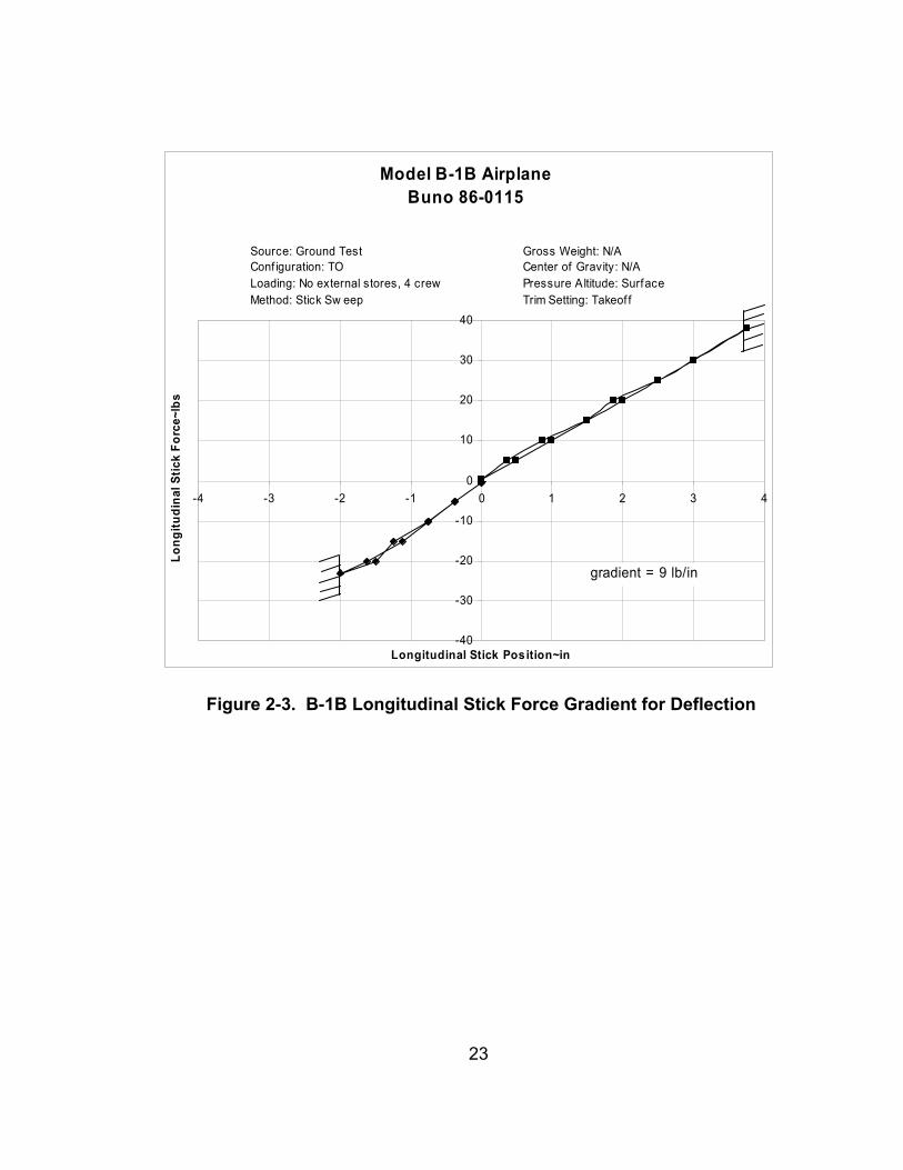
could result in an aircraft overstress. The stick forces generally felt heavy, which,
over time could lead to fatigue. Classical quantitative flight test techniques were
used to document the stick force gradient, which plots the amount of force
required for a given amount of stick deflection as well as for load factor. Because
the B-1B provides artificial feel to the pilot through the use of bungees, stick
forces versus deflections were measured on the ground with a hand held force
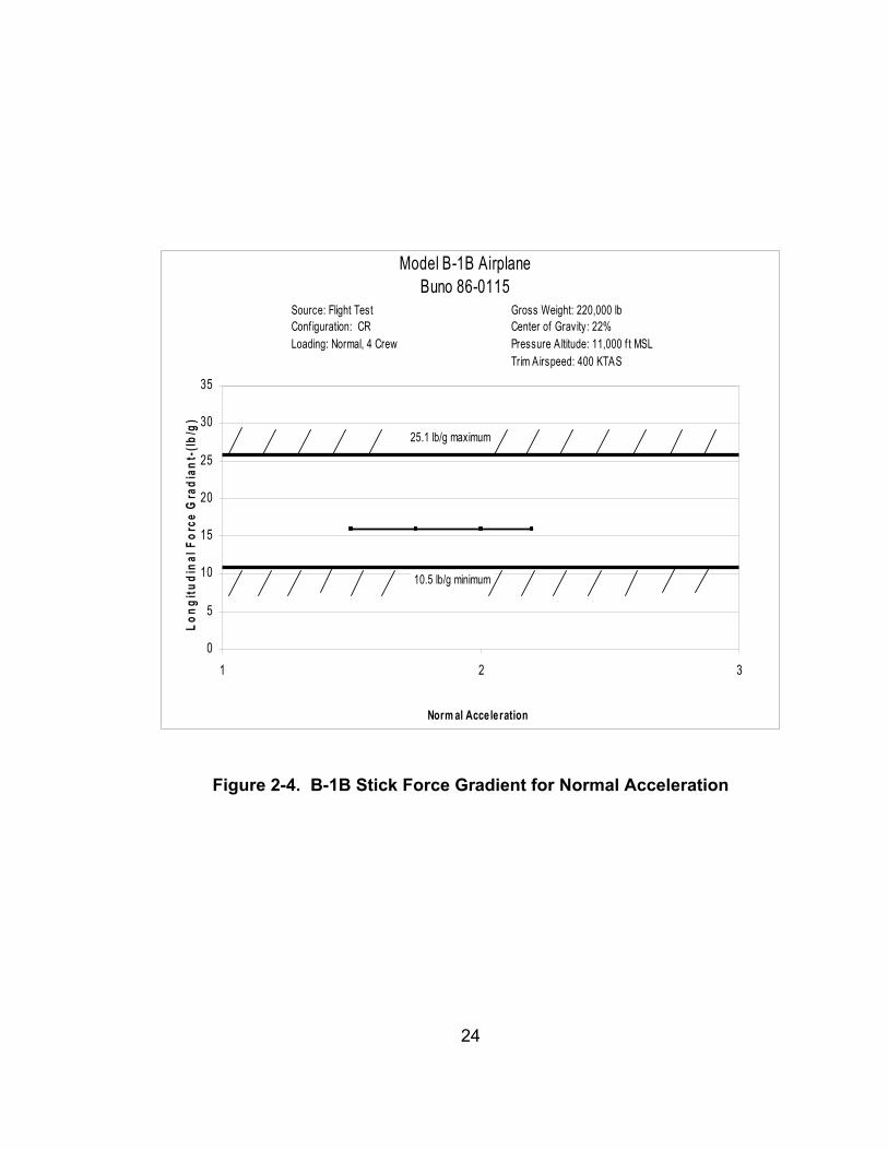
gauge. The results are shown in Figure 2-3. Airborne, the amount of force per g
level was measured and it was found that this gradient was moderately high,
though constant, at 16 pounds per g (Figure 2-4). A stick force per g gradient of
this magnitude will generally result in the aircraft feeling like a transport aircraft
with a sense that it is very stable, with the high forces preventing quick response.
Regardless, the qualities exhibited by the B-1B will aid the pilot in not exceeding
prescribed g limits.
23
-40
-30
-20
-10
0
10
20
30
40
-4 -3 -2 -1 0 1 2 3 4
Longitudinal Stick Position~in
Long
itudi
nal S
tick
Forc
e~lb
s
Source: Ground TestConf iguration: TOLoading: No external stores, 4 crewMethod: Stick Sw eep
Gross Weight: N/ACenter of Gravity: N/APressure Altitude: SurfaceTrim Setting: Takeof f
Model B-1B AirplaneBuno 86-0115
gradient = 9 lb/in
Figure 2-3. B-1B Longitudinal Stick Force Gradient for Deflection
24
0
5
10
15
20
25
30
35
1 2 3
Norm al Acceleration
Long
itudi
nal F
orce
Gra
dian
t-(lb
/g)
25.1 lb/g maximum
10.5 lb/g minimum
Model B-1B AirplaneBuno 86-0115
Source: Flight TestConf iguration: CR Loading: Normal, 4 Crew
Gross Weight: 220,000 lbCenter of Gravity: 22%Pressure A ltitude: 11,000 f t MSLTrim Airspeed: 400 KTAS
Figure 2-4. B-1B Stick Force Gradient for Normal Acceleration
25
A series of aggressive turns was attempted utilizing lateral stick deflection
of approximately 1 ½ inches. The goal was to roll the aircraft as precisely as
possible to 60 degrees angle of bank. The maneuvers were conducted at 540
knots ground speed during a low level bombing run at 1000 feet above ground
level. Using smooth but deliberate lateral stick inputs, the aircraft response was
unpredictable in that the initially slow roll rate increased rapidly passing
approximately ½ inch lateral stick deflection, resulting in an overshoot of 5°. To
compensate, a well timed lateral input in the opposite direction was required of
approximately ½ inch past neutral and then back to neutral, leading the desired
angle of bank by approximately 5°. This allowed the pilot to consistently get
within 5° of the desired bank angle. The imprecise ability to roll the aircraft to a
specific angle of bank will make this task intensive; however, there is no effect on
the delivery of JDAM ordnance. Generally speaking, the delivery of JDAM
ordnance is conducted from a more or less wings-level attitude, whether in a
dive, a climb, or level flight.
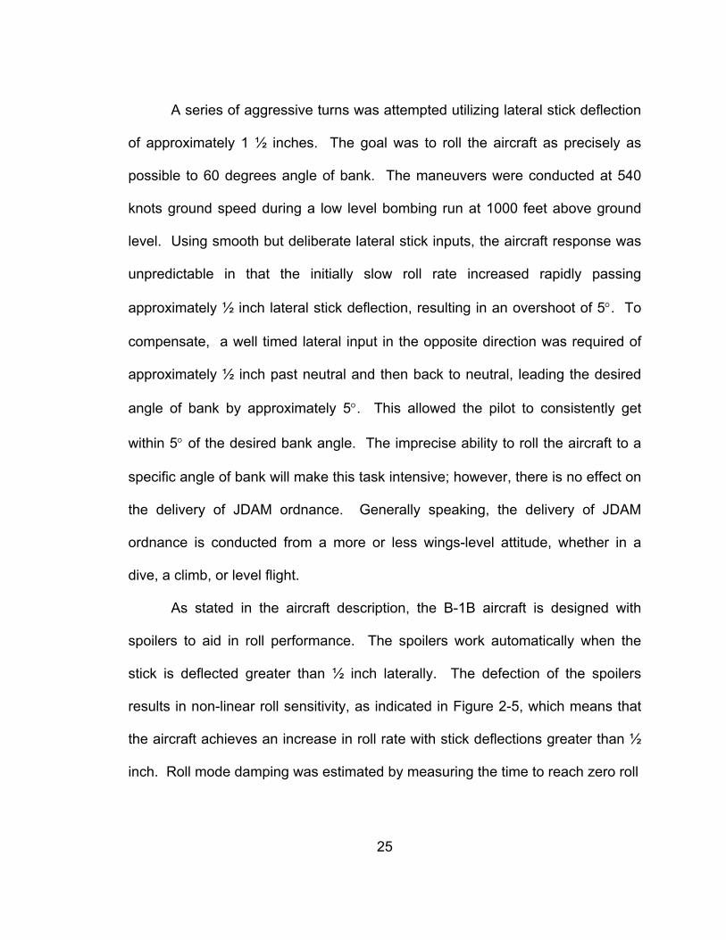
As stated in the aircraft description, the B-1B aircraft is designed with
spoilers to aid in roll performance. The spoilers work automatically when the
stick is deflected greater than ½ inch laterally. The defection of the spoilers
results in non-linear roll sensitivity, as indicated in Figure 2-5, which means that
the aircraft achieves an increase in roll rate with stick deflections greater than ½
inch. Roll mode damping was estimated by measuring the time to reach zero roll
26
Left Rolls
0123456789
10
0 10 20 30 40
Steady Roll Rate - (deg/sec)
Late
ral S
tick
Forc
e - (
lbs)
CR55, 15,000 ft,30% C.G.PA, 11,000 ft, 18% C.G.
Source: Flight TestConf iguration: CRLoading: No External StoresMethod: 1 g Steady State Rolls
Model B-1B AirplaneBuno 86-0115
Figure 2-5. B-1B Roll Sensitivity
27
rate from a steady roll rate, following the re-centering of the stick. From this, the
roll mode time constants were estimated 0.3 seconds in configuration PA
(landing configuration) and 0.5 seconds in CR (gear and flaps up with the wing
sweep set at 25 degrees) by dividing the time by 3. The roll mode time constant
gives an indication of just how long the aircraft will continue to roll once the input
is removed and is a function of roll damping and rolling moments of inertia (how
much momentum the aircraft has once it gets going and how long it will take it to
stop without control inputs). The non-linear roll sensitivity combined with the long
roll mode time constant are the likely cause of the imprecise bank angle capture.
2.3.3.7 Landing
Regardless of the massive payload that an aircraft may have, it is of little
use if landing that aircraft is hazardous. The landing characteristics of the B-1B
aircraft were evaluated for this very reason. Many of the hazards associated with
flying occur during takeoff and landing. It is at this time that the aircraft is close
to the ground, at slower airspeeds, and in the midst of changing aircraft
configurations (lowering or raising the gear and flaps). The B-1B exhibited
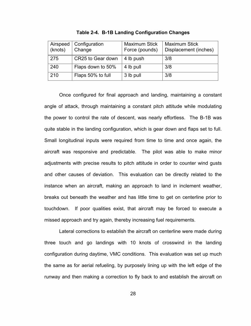
excellent qualities with regard to configuration changes, as depicted in Table 2-4.
The small forces and stick displacements allow the pilot to make smooth
transitions while changing configurations.
28
Table 2-4. B-1B Landing Configuration Changes
Airspeed (knots)
Configuration Change
Maximum Stick Force (pounds)
Maximum Stick Displacement (inches)
275 CR25 to Gear down 4 lb push 3/8
240 Flaps down to 50% 4 lb pull 3/8
210 Flaps 50% to full 3 lb pull 3/8
Once configured for final approach and landing, maintaining a constant
angle of attack, through maintaining a constant pitch attitude while modulating
the power to control the rate of descent, was nearly effortless. The B-1B was
quite stable in the landing configuration, which is gear down and flaps set to full.
Small longitudinal inputs were required from time to time and once again, the
aircraft was responsive and predictable. The pilot was able to make minor
adjustments with precise results to pitch attitude in order to counter wind gusts
and other causes of deviation. This evaluation can be directly related to the
instance when an aircraft, making an approach to land in inclement weather,
breaks out beneath the weather and has little time to get on centerline prior to
touchdown. If poor qualities exist, that aircraft may be forced to execute a
missed approach and try again, thereby increasing fuel requirements.
Lateral corrections to establish the aircraft on centerline were made during
three touch and go landings with 10 knots of crosswind in the landing
configuration during daytime, VMC conditions. This evaluation was set up much
the same as for aerial refueling, by purposely lining up with the left edge of the
runway and then making a correction to fly back to and establish the aircraft on
29
centerline. The maneuver was conducted at 1000 feet above ground level. With
lineup established on the left edge of the runway (approximately 150 feet lateral
offset), a right lateral stick displacement of approximately 2 inches was applied to
correct to centerline with a small power addition. Approaching centerline, a
lateral stick deflection of approximately 1 inch in the opposite direction, in
conjunction with a small power reduction was made. The aircraft response was
crisp and predictable, with no yawing tendencies noted. Capturing centerline
was simple and non-objectionable, requiring two small lateral stick inputs over a
three second period.
Once established on centerline, it was desirous to maintain that position
all the way to touchdown. Established on final approach at 800 ft AGL, the
aircraft began to slowly drift left due to the 10 knot crosswind. A lateral stick
deflection opposite the direction of drift of approximately 1 inch was applied to
establish a crab into the wind. Once established on the desired heading, the
stick was returned to neutral and a constant heading crab was flown to
approximately 150 ft AGL. The aircraft was very stable both laterally and
directionally, making it easy to maintain centerline with 1/8 inch stick deflections
every 3-5 seconds. At 150 ft AGL, approximately ¼ inch of left rudder was
applied to align the aircraft with the runway heading, which required
approximately ½ inch of right stick and a small power addition to maintain a
constant heading and rate of descent. There were no adverse characteristics or
lightening of forces, which made maintaining centerline all the way to touchdown
easy to accomplish.
30
For the full stop landing, aircraft gross weight was 208,000 pounds and
the center of gravity was 17% mean aerodynamic chord. The ground roll
distance to a speed of 10 knots was impressive in that it was only 3,700 feet with
moderate braking. The short landing distance allows for flexibility in mission
planning in that the B-1B is able to land at a multitude of military and civilian
airfields.
2.4 B-1B JDAM Capabilities The B-1B’s initial design as a nuclear bomber would have kept its lethality
from being utilized in most conflicts of our times. Using nuclear weapons would
have political ramifications from which the United States would have great
difficulty in recovering. In 1993, the Air Force began a transition program in
which the B-1B was converted to a conventional Bomber. The program was
called the Conventional Mission Upgrade Program (CMUP). The initial program
included the means to carry 84 Mk-82 500-pound bombs. However, dumb
bombs in a political environment requiring precision weapons would not suffice,
due to the potential for collateral damage. Upgrades continued to include cluster
weapons, improvements to offensive and defensive systems, and communication
systems upgrades to include the addition of GPS, the critical link for precision
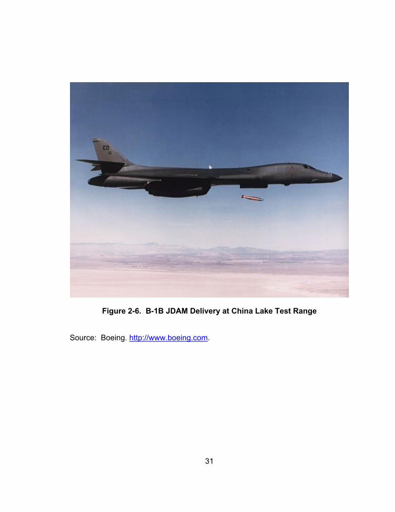
munitions. The first JDAM ever dropped from a B-1B occurred on Feb 11, 1998
at the China Lake test range Figure 2-6. The weapon impacted 22 feet from its
31
Figure 2-6. B-1B JDAM Delivery at China Lake Test Range
Source: Boeing. http://www.boeing.com.
32
intended point of impact after being released from 22,000 feet mean sea level. In
April 1998, the first of the B-1B GPS upgrade kits arrived at Tinker Air Force
Base and so began the upgrade to fleet B-1Bs. The effectiveness of JDAM
became apparent in Kosovo when, used for the first time in combat, the weapons
destroyed a number of bridges that had survived numerous attacks with laser
guided bombs.
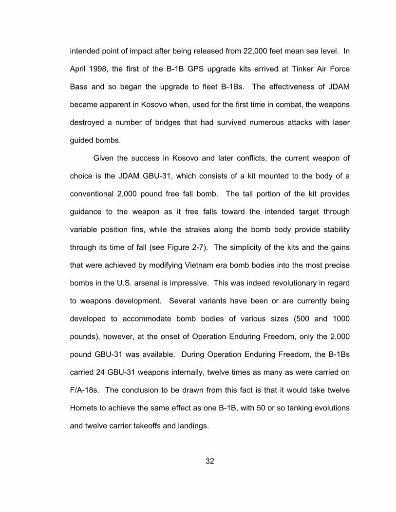
Given the success in Kosovo and later conflicts, the current weapon of
choice is the JDAM GBU-31, which consists of a kit mounted to the body of a
conventional 2,000 pound free fall bomb. The tail portion of the kit provides
guidance to the weapon as it free falls toward the intended target through
variable position fins, while the strakes along the bomb body provide stability
through its time of fall (see Figure 2-7). The simplicity of the kits and the gains
that were achieved by modifying Vietnam era bomb bodies into the most precise
bombs in the U.S. arsenal is impressive. This was indeed revolutionary in regard
to weapons development. Several variants have been or are currently being
developed to accommodate bomb bodies of various sizes (500 and 1000
pounds), however, at the onset of Operation Enduring Freedom, only the 2,000
pound GBU-31 was available. During Operation Enduring Freedom, the B-1Bs
carried 24 GBU-31 weapons internally, twelve times as many as were carried on
F/A-18s. The conclusion to be drawn from this fact is that it would take twelve
Hornets to achieve the same effect as one B-1B, with 50 or so tanking evolutions
and twelve carrier takeoffs and landings.
33
Figure 2-7. JDAM Schematic
Source: http://www.fas.org, modified by the author.
34
3 Operation Enduring Freedom and the B-1B
The B-1B was used extensively during Operation Enduring Freedom,
primarily operating from Diego Garcia, a small island located in the Indian Ocean
nearly 3,000 miles away. Only eight B-1Bs were deployed, yet the
accomplishments of the B-1B speak for themselves. Flying less than 10% of the
interdiction sorties, B-1Bs delivered over 40 percent of the total bombs during the
first six months of Operation Enduring Freedom. Of that, they dropped a
reported 3,900 JDAMs, 67% of the total JDAMs dropped by all U.S. forces. All in
all, the B-1B dropped more ordnance than any other aircraft type in the U.S.
inventory. Afghanistan showed that the bomber was still "king" – the reliable…
B-1s… will show that they are still vital items in the US arsenal [Defense Systems
Daily, 2002]. Only one B-1B was lost during the conflict, not due to battle
damage but to a system malfunction. The aircrew ejected near Diego Garcia and
were rescued.
35
4 Summary
The B-1B has excellent overall flying qualities with some minor issues that
do not greatly affect mission success. Taking off and landing the aircraft is easy
to do, and the distance required to do both allow it to operate from a variety of
airfields and provides flexibility in planning. Airborne, the aircraft flies nicely, with
only minor problems in the lateral and longitudinal axis. If required, it can refuel
while airborne and further increase its impressive range and endurance.
Capable of safely getting to the fight and being able to stay at the fight for
extended periods of time, the B-1B need only the proper weaponry to be the
complete package. With the advent of JDAM munitions and future smart
weapons capabilities, its utility cannot be matched.
36
5 Conclusions and Recommendations
The B-1B demonstrates excellent overall flying qualities, particularly in
mission critical areas, and possesses a robust payload and intercontinental
range that make it a formidable weapons platform. Though carrier aviation has
its advantage of being able to effectively position a U.S. airfield in many remote
locations, often times more quickly than the logistics involved in establishing a
U.S. Air Force operation allow, the lethality of the B-1B cannot be overlooked.
The F/A-18 performs several missions well, but since its inception in the early
1980s, critics have expressed concern over its limited range and endurance.
To perform the long range interdiction mission, the aircraft must have the
capability to travel large distances prior to accurately putting bombs on target.
The nature of our conflicts dictates such, particularly in land locked locations
such as Afghanistan. The U.S. has demonstrated that through a complex
scheme of aerial refueling, made possible by complicated logistical plans, the
Hornet can get there, but at the expense of the U.S. Air Force tankers. In the
course of a mission, the Hornet must take on approximately 35,000 pounds of
fuel while airborne. Due to its small size, this was accomplished during multiple
refueling evolutions, at night, or in inclement weather. It has been shown that the
B-1B possesses an unrefueled range of over 3,500 nautical miles, which
eliminates the need for multiple refueling events. During the course of the
missions, Hornet pilots grew more and more fatigued due to sitting in a confined
cockpit and wearing NVDs for several hours. Depending on whether the mission
37
was preplanned, in which the aircrew took off with designated targets, or they
received tasking once airborne, B-1B aircrew could expect no more than one or
two tanking evolutions (none for preplanned targets), had the luxury of a large
crew station with enough room for the crew to at least stand up and stretch from
time to time, and because of single aircraft operations, were not required to wear
NVDs for formation keeping.
And, once on the scene, the F/A-18s couldn’t stay nearly as long and were
no more capable of delivering JDAM than the B-1B. Even when there was
enough airborne fuel, the Hornets repeatedly had to leave the target area and
return to the tanker, which proved to limit their effectiveness due to the constant
breaks in communication with the ground forces for which they were providing
support. On several occasions, Hornets received requests for immediate
support, relayed through the tanker aircraft, while they were receiving fuel. They
would be forced to terminate the fueling evolution to return to the target area,
arrive late and miss a time sensitive opportunity, or deny the support, which was
the sole reason for their being there in the first place. The B-1Bs remained on
station for hours, while maintaining constant communication with ground forces,
and were rarely forced to break the lines of communication or leave the target
area in order to refuel.
Most importantly, the effects obtained from the B-1B’s twenty-four JDAMs
dwarf that of a section of Hornets, for it would take twelve F/A-18s to generate
the same effects. Military planners have learned over the years that effects-
based warfare is the most effective way to win battles. Rather than the random
38
destruction of enemy assets, targets are selected and destroyed to achieve a
desired effect, to bring us toward a strategic goal which has been determined as
necessary for a desired outcome of the conflict.
Hornet pilots routinely fought to stay awake during the long transit back to
the carrier, eating sugar filled protein bars or drinking caffeine. Sometimes, the
only thing that could alleviate the drowsiness was the sun rising on the horizon
after a long flight that started in total darkness. Lastly, they had to perform the
carrier landing in an unforgiving environment, while fighting the effects of fatigue.
In contrast, the B-1B had a crew of four, two of which were pilots so that the
duties of flying the aircraft were shared. Landing on a 12,000 foot, stationary,
well lit runway was dangerous only in that its simplicity could cause the crew to
become complacent.
Not to say that the smaller interdiction aircraft such as the F/A-18 do not
play a vital role in strike warfare, particularly when a quick response is required
or when the potential for an air-to-air engagement exists, but when the bombing
campaign begins and air supremacy has been established, there is no better
platform than the B-1B. The B-1B is undergoing many upgrades to avionics,
offensive and defensive systems, and to smart weapons capabilities. These
efforts should be continued. The B-1B has not reached its full potential, yet
already has staked its place in history as one of the best ever. With the advent of
GPS guided munitions, whose accuracy is second to none and is not dependant
upon the platform, the B-1B must be considered the weapons platform of choice

39
for long range interdiction missions due to its flying qualities, superior range and
endurance, and its unmatched payload capability.

40
List of References
41
List of References
1. USNTPS Flight Test Manual 103 (FTM 103), Fixed Wing Stability and Control Theory and Flight Test Techniques Manual, January 1997.
2. USNTPS Flight Test Manual 108 (FTM 108), Fixed Wing Performance Manual, 30 Sep 1992.
3. Flight Manual, USAF Series B-1B Aircraft, TO 1B-1B-1-1, 15 July 1996.
4. Weapon Systems Officer's Flight Manual, USAF Series B-1B Aircraft, TO 1B-1B-1-2, 15 July 1998.
5. Flying Standards, 184th Operations Group Operating Instruction 11-7, 1
June 1996.
6. Local Operating Procedures, AFI 11-2B-1 Volume 3 Chapter 8, Kansas Air National Guard, 1 September 1998.
7. Learjet Flight Syllabus and Background Material for the US Air Force/US Naval Test Pilot School Variable Stability Programs. Buffalo: Calspan, 27 April 1998.
8. Air Force Link.http://www.af.mil (viewed February 2005).
9. Global Security.http://globalsecurity.org (viewed February 2005).
10. Boeing.http://www.boeing.com (viewed February 2005).
11. B-1B Drops first GPS-Guided JDAM, Wright Patterson AFB Skywrighter, Mar 98.http://www.fas.org (viewed February 2005).
12. The Bargain Basement Bomb, Long Island Newsday, 14 November 1999. http://www.fas.org. (viewed February 2005).
13. Defense Systems Daily, Iraq Attack: Key Factors, The New Face of Warfare?, September 2002.http://defence-data.com/index2/pageda27.htm (viewed February 2005).
42
Vita
Stanley Jones was born in West Germany in 1965, is the son of an Army
Officer, and grew up in various locations around the world before moving to
Memphis, TN in 1979. He graduated from Sheffield High School in 1983 and
enrolled at the University of Tennessee, Knoxville. He was a member of the
1985 Southeastern Conference Championship football team and in 1988, he
graduated with a B.S. in Industrial Engineering. In 1991, he joined the United
States Navy and became an F/A-18 fighter pilot. In 1997 he was selected to
attend the United States Naval Test Pilot School and graduated with Class 115 in
June 1999. Throughout his naval career, he has made four extended
deployments in support of many U.S. operations. Most recently, he flew combat
missions in support of Operation Enduring Freedom in Afghanistan and earned
two strike flight air medals.
He currently resides in Virginia Beach, VA with his lovely wife Gina, his
beautiful daughters Kennedy, Morgan, and Sydney, and his two rambunctious
labs Rocky and Duke.
Related Documents