Florida International University FIU Digital Commons FIU Electronic eses and Dissertations University Graduate School 11-12-2009 Effective Reconfigurable Antenna Designs to Enhance Performance and Enable Wireless Powering Shishir S. Punjala Florida International University, spunj001@fiu.edu Follow this and additional works at: hp://digitalcommons.fiu.edu/etd Part of the Electromagnetics and Photonics Commons , and the Other Electrical and Computer Engineering Commons is work is brought to you for free and open access by the University Graduate School at FIU Digital Commons. It has been accepted for inclusion in FIU Electronic eses and Dissertations by an authorized administrator of FIU Digital Commons. For more information, please contact dcc@fiu.edu. Recommended Citation Punjala, Shishir S., "Effective Reconfigurable Antenna Designs to Enhance Performance and Enable Wireless Powering" (2009). FIU Electronic eses and Dissertations. Paper 108. hp://digitalcommons.fiu.edu/etd/108

Welcome message from author
This document is posted to help you gain knowledge. Please leave a comment to let me know what you think about it! Share it to your friends and learn new things together.
Transcript

Florida International UniversityFIU Digital Commons
FIU Electronic Theses and Dissertations University Graduate School
11-12-2009
Effective Reconfigurable Antenna Designs toEnhance Performance and Enable WirelessPoweringShishir S. PunjalaFlorida International University, [email protected]
Follow this and additional works at: http://digitalcommons.fiu.edu/etd
Part of the Electromagnetics and Photonics Commons, and the Other Electrical and ComputerEngineering Commons
This work is brought to you for free and open access by the University Graduate School at FIU Digital Commons. It has been accepted for inclusion inFIU Electronic Theses and Dissertations by an authorized administrator of FIU Digital Commons. For more information, please contact [email protected].
Recommended CitationPunjala, Shishir S., "Effective Reconfigurable Antenna Designs to Enhance Performance and Enable Wireless Powering" (2009). FIUElectronic Theses and Dissertations. Paper 108.http://digitalcommons.fiu.edu/etd/108

FLORIDA INTERNATIONAL UNIVERSITY
Miami, Florida
EFFECTIVE RECONFIGURABLE ANTENNA DESIGNS TO ENHANCE
PERFORMANCE AND ENABLE WIRELESS POWERING
A dissertation submitted in partial fulfillment of the
requirements for the degree of
DOCTOR OF PHILOSOPHY
in
ELECTRICAL ENGINEERING
by
Shishir Shanker Punjala
2009

iii
To: Dean Amir Mirmiran College of Engineering and Computing
This dissertation, written by Shishir Shanker Punjala, and entitled Effective Reconfigurable Antenna Designs to Enhance Performance and Enable Wireless Powering, having been approved in respect to style and intellectual content, is referred to you for judgment.
We have read this dissertation and recommend that it be approved.
__________________________________ Kia Makki
__________________________________
Syed Ahmed
__________________________________ Deng Pan
__________________________________
Kang Yen
__________________________________ Niki Pissinou, Major Professor
Date of Defense: November 12, 2009 This dissertation of Shishir Shanker Punjala is approved.
__________________________________ Dean Amir Mirmiran
College of Engineering and Computing
__________________________________ Dean George Walker
University Graduate School
Florida International University, 2009

iv
© Copyright 2009 by Shishir Shanker Punjala
All rights reserved.

v
DEDICATION
To my father, mother and sister

vi
ACKNOWLEDGMENTS
I would like to express my gratitude to the Telecommunications and Information
Technology Institute at FIU for providing me with a family oriented environment that made
this research possible. I am indebted to all the faculty members and researchers, who have
supported, helped, encouraged, and advised me throughout the course of my research.
This dissertation would not have been into existence if it was not for my advisor Prof.
Niki Pissinou, who has not only mended my misguided approach to research, but also served
as a role model for me to live a successful and happy life as a researcher. She made sure that I
am always focused and never deviate from the objectives of research. I would like to specially
thank Dr. Kia Makki for his guidance, support and encouragement. If it hadn’t been for Dr.
Makki’s advice at critical junctures of my career, I would have never crossed over from being
a Masters student to a PHD student. My special thanks to Dr. Kang Yen, Dr. Deng Pan and Dr.
Syed M. Ahmad who have taken out their valuable time to evaluate my dissertation.
Without my mother’s love and guidance and my sister’s support, I would never have
been able to finish this dissertation.
vii
ABSTRACT OF THE DISSERTATION
EFFECTIVE RECONFIGURABLE ANTENNA DESIGNS TO ENHANCE
PERFORMANCE AND ENABLE WIRELESS POWERING
by
Shishir Shanker Punjala
Florida International University, 2009
Miami, Florida
Professor Niki Pissinou, Major Professor
With the increase in traffic on the internet, there is a greater demand for wireless
mobile and ubiquitous applications. These applications need antennas that are not only
broadband, but can also work in different frequency spectrums. Even though there is a greater
demand for such applications, it is still imperative to conserve power. Thus, there is a need to
design multi-broadband antennas that do not use a lot of power. Reconfigurable antennas can
work in different frequency spectrums as well as conserve power. The current designs of
reconfigurable antennas work only in one band. There is a need to design reconfigurable
antennas that work in different frequency spectrums. In this current era of high power
consumption there is also a greater demand for wireless powering. This dissertation explores
ideal designs of reconfigurable antennas that can improve performance and enable wireless
powering. This dissertation also presents lab results of the multi-broadband reconfigurable
antenna that was created. A detailed mathematical analyses, as well as extensive simulation
results are also presented. The novel reconfigurable antenna designs can be extended to
Multiple Input Multiple Output (MIMO) environments and military applications.

viii
TABLE OF CONTENTS
CHAPTER PAGE
1 Introduction ............................................................................................................ …………...1 1.1 Background ..................................................................................................... …………...1 1.2 Motivation ...................................................................................................... …………...2 1.3 Research Problem ........................................................................................... …………...2 1.4 Significance and Contribution ........................................................................ …………...3 1.5 Methodology ................................................................................................... …………...3 1.6 Organization of the Dissertation ..................................................................... …..……….4
2 Related Work .......................................................................................................... ……..…….5 2.1 Introduction .................................................................................................... …………...5 2.2 Antenna Theory .............................................................................................. ……..…….5 2.3 Types of Antenna ........................................................................................... …………...6
2.3.1 Dipole Antennas ........................................................................................ …………...6 2.3.2 Array Antennas ......................................................................................... …………...7 2.3.3 Fractal Antennas ........................................................................................ …………...8 2.3.4 Microstrip Antennas .................................................................................. …………...8 2.3.5 Microstrip Fractal Patch Antennas ............................................................ …………...9
2.4 Theory of Plane Waves................................................................................... ………….10 2.4.1 Normal Incidence ...................................................................................... ………….10 2.4.2 Oblique Incidence ..................................................................................... ………….12
2.4.2.1 Snell’s Law of Reflection .................................................................... ………….12 2.4.2.2 Perpendicular Polarization ................................................................... ………….13 2.4.2.3 Parallel Polarization ............................................................................. ………….14 2.4.2.4 Brewster’s Angle ................................................................................. ………….16
2.4.2.4.1 Perpendicular Polarization ............................................................. ………….16 2.4.2.4.2 Parallel Polarization ....................................................................... ………….16
2.5 Permittivity of Concrete ................................................................................. ………….17 2.6 Radio Frequency Spectrum ............................................................................ ………….19
2.6.1 Extremely Low and Very Low Frequencies (ELF & VLF) (<30 KHz) .. ………….19 2.6.2 Ionosphere ................................................................................................. ………….20 2.6.3 Low and Medium Frequencies (LF & MF) (30 KHz to 3 MHz) .............. ………….20 2.6.4 High Frequencies (HF) (3 to 30 MHz) ...................................................... ………….21 2.6.5 Very High Frequencies and Ultrahigh Frequencies (VHF & UHF) (30 MHz to 3 GHz) ............................................................................................................ ………….21 2.6.6 Above Ultra High Frequencies (Above 3 GHz) ........................................ ………….21 2.6.7 UWB Systems ........................................................................................... ………….21
2.7 Wireless Powering .......................................................................................... ………….21 2.7.1 Current Consumption of Typical Sensors ................................................. ………….23
2.8 Antenna Simulation Parameters ..................................................................... ………….23 2.8.1 S- Parameters ............................................................................................ ………….23 2.8.2 Directivity ................................................................................................. ………….24 2.8.3 VSWR ....................................................................................................... ………….25
2.9 Reconfigurable Antennas ............................................................................... ………….25 2.9.1 Reconfigurable Sierpinski Gasket Antenna .............................................. ………….26

ix
2.9.1.1 Reworked Results of the Reconfigurable Sierpinski Gasket Antenna ………….27 2.9.1.2 Data Analysis and Shortcomings ......................................................... ………….31
2.9.2 Reconfigurable Planar Inverted Fractal Antenna (RPIFA) ...................... ………….31 2.9.2.1 Reworked Results of the Reconfigurable Planar Inverted Fractal Antenna (RPIFA) ........................................................................................................... ………….32 2.9.2.2 Data Analysis and Shortcomings ......................................................... ………….35
2.10 Summary ....................................................................................................... ………….35
3 Wireless Powering in a Concrete Slab ................................................................... ………….36 3.1 Introduction .................................................................................................... ………….36 3.2 Uniform Plane Waves in a Concrete Medium-Principal Axis and Oblique Angle .................................................................................................................... ………….37
3.2.1 Direction of Propagation of a Uniform Plane Wave ................................. ………….38 3.3 Power received by an antenna ........................................................................ ………….39 3.4 3D Fractal Hilbert Dipole Antennas ............................................................... ………….40 3.5 Power Accepted .............................................................................................. ………….42 3.6 Simulations and Results.................................................................................. ………….42 3.7 Additional Simulations and Results ............................................................... ………….46 3.8 Summary ......................................................................................................... ………….47
4 Reconfigurable Antennas & Wireless Powering .................................................... ………….48 4.1 Introduction .................................................................................................... ………….48 4.2 Reconfigurable Antennas vs. Dipoles for Wireless Powering ....................... ………….48 4.3 Reconfigurable Planar Inverted Sierpinski Gasket Fractal Antenna (RPISGFA) ............................................................................................ ………….49 4.4 Simulations and Results of the RPISGFA ...................................................... ………….51 4.5 Data Analysis .................................................................................................. ………….55 4.6 Simulations and Results of the RPISGFA in a concrete slab ......................... ………….55 4.7 Additional Simulations and Results of the RPISGFA in a concrete slab ....... ………….57 4.8 Data Analysis .................................................................................................. ………….59 4.9 Simulations and Results of the Planar Reconfigurable Inverted Fractal Antenna in a concrete slab .................................................................................... ………….59 4.10 Summary ....................................................................................................... ………….62
5 Rectangular Reconfigurable Antenna (RRA) with Ultra Wideband Tuning Ability ........................................................................................................................ ………….63
5.1 Introduction. ................................................................................................... ………….63 5.2 RRA ................................................................................................................ ………….64 5.3 Design of the RRA ......................................................................................... .................64
5.3.1 Printed Circuit Boards ............................................................................... .................65 5.3.2 Antenna Design ......................................................................................... .................65
5.3.2.1 Cavity Model ....................................................................................... ………….66 5.3.2.1.1 Field Configurations (Modes) - ............................................. ………….67 5.3.2.1.2 Fields Radiated (Radiating Slots) - ................................... ………….69
5.3.2.2 Directivity ............................................................................................ ………….70 5.3.2.3 Transmission Line Model .................................................................... ………….71
5.3.2.3.1 Conductance ................................................................................... ………….73 5.4 Simulation of the RRA ................................................................................... ………….76

x
5.4.1 Simulation of the RRA with a coaxial probe feed .................................... ………….77 5.4.2 Data Analysis ............................................................................................ ………….83 5.4.3 Simulation of the RRA with a slot feed .................................................... ………….83 5.4.4 Data Analysis ............................................................................................ ………….88
5.5 Lab Results ..................................................................................................... ………….88 5.6 Summary ......................................................................................................... .................92
6 Conclusions and Future Work ................................................................................ ………….93 6.1 Future Work .................................................................................................... ………….94
BIBLIOGRAPHY ..................................................................................................... ………….96
VITA ......................................................................................................................... ...............102

xi
LIST OF FIGURES
FIGURE PAGE
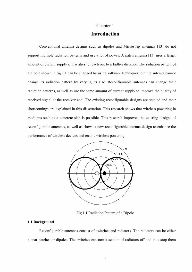
1.1 Radiation Pattern of a Dipole .............................................................................. …………...1
2.1 Transmission System ........................................................................................... …………...6
2.2 Dipole Antenna.................................................................................................... …………...6
2.3 Array Antenna ..................................................................................................... …………...7
2.4 Fractal Antenna ................................................................................................... …………...8
2.5 Microstrip Antenna.............................................................................................. …………...9
2.6 Microstrip Antenna with fractal geometries ........................................................ ………….10
2.7 Plane Wave reflection and transmission for normal incidence ........................... ………….11
2.8 Plane Wave reflection and transmission for perpendicular polarization ............. ………….13
2.9 Plane Wave reflection and transmission for parallel polarization ....................... ………….15
2.10 Relative Permittivity of Concrete for the first Debye Model ............................ ………….18
2.11 Relative Permittivity of Concrete for the second Debye Model ....................... ………….19
2.12 Wireless Power Transmission ........................................................................... ………….23
2.13 Reconfigurable Sierpinski Gasket Antenna ...................................................... ………….26
2.14 Reconfigurable Sierpinski Gasket Antenna with iterations .............................. ………….26
2.15 Simulated Reconfigurable Sierpinski Gasket Antenna ..................................... ………….27
2.16 Input Return Loss for the first iteration ................................................... ………….28
2.17 Input Return Loss for the second iteration .............................................. ………….28

xii
2.18 VSWR for the first iteration .............................................................................. ………….29
2.19 VSWR for the second iteration ......................................................................... ………….29
2.20 Radiation Pattern for the first iteration .............................................................. ………….30
2.21 Radiation Pattern for the second iteration ......................................................... ………….30
2.22 Reconfigurable PIFA Antenna [1] .................................................................... ………….31
2.23 Input Return Loss ( ) at lumped port 1 .......................................................... ………….32
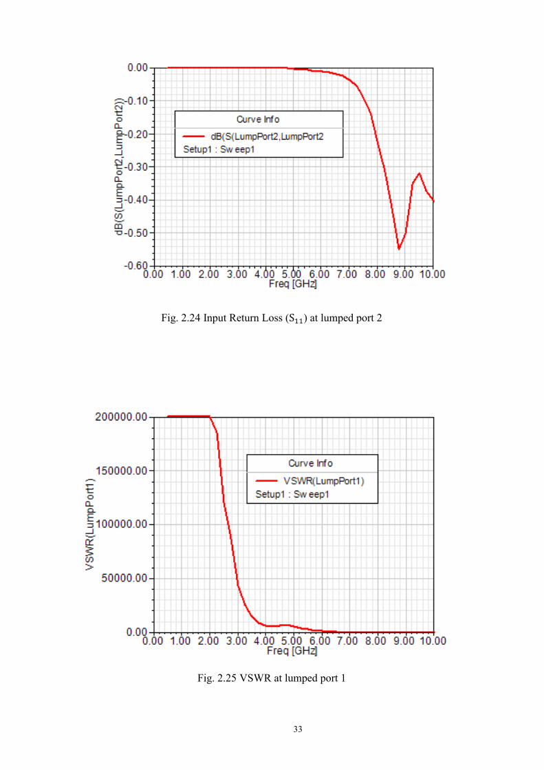
2.24 Input Return Loss ( ) at lumped port 2 .......................................................... ………….33
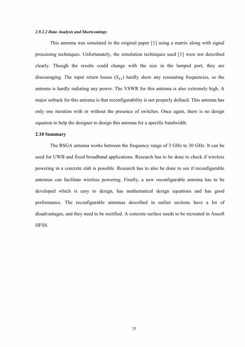
2.25 VSWR at lumped port 1 .................................................................................... ………….33
2.26 VSWR at lumped port 2 .................................................................................... ………….34
2.27 Radiation Pattern for the Reconfigurable PIFA Antenna .................................. ………….34
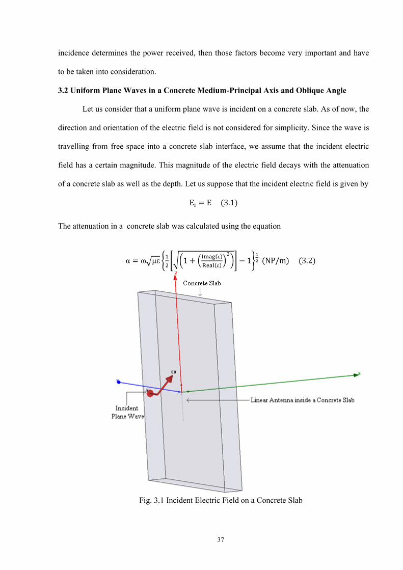
3.1 Incident Electric Field on a Concrete Slab .......................................................... ………….37
3.2 3D Fractal Hilbert Dipole Antenna [18] ............................................................. ………….41 3.3 Input Return Loss S 11 (dB) of the surface of the Concrete slice.......................... ………….43
3.4 Electric Field inside a concrete slice (0.2 %) for the incident electric field having X and Y components ..................................................................................... ………….43
3.5 Electric Field inside a concrete slice (12 %) for the incident electric field having X and Y components ..................................................................................... ………….44
3.6 Electric Field inside a concrete slice (12 %) for the incident electric field having an X component ............................................................................................. ………….44
3.7 Electric Field inside a concrete slice (0.2 %) for the incident electric field having an X component ............................................................................................. ………….45
3.8 Power received by a Hilbert 3D-2 Antenna for the First Debye model of relative permittivity of concrete ................................................................................ ………….45

xiii
3.9 Input Return Loss S 11 (dB) of the surface of the concrete slice .......................... ………….46
3.10 Electric Field inside the concrete slice .............................................................. ………….46
4.1 RPISGFA............................................................................................................. ………….51
4.2 Input Return Loss for the first iteration ..................................................... ………….52
4.3 Input Return Loss for the second iteration ................................................ ………….52
4.4 Radiation Pattern for the first iteration ................................................................ ………….53
4.5 Radiation Pattern for the second iteration ........................................................... ………….53
4.6 VSWR for the first iteration ................................................................................ ………….54
4.7 VSWR for the second iteration ........................................................................... ………….54
4.8 Input Return Loss for a concrete slab (0.2 % moisture content), having the RPISGFA 12 cm inside it ........................................................................ ………….55
4.9 Input Return Loss for a concrete slab (12 % moisture content), having the RPISGFA 12 cm inside it ........................................................................ ………….56
4.10 Electric fields on the surface of the RPISGFA buried inside a concrete slab having 0.2% moisture content............................................................................ ………….56
4.11 Electric fields on the surface of the RPISGFA buried inside a concrete slab having 12 % moisture content........................................................................... ………….57
4.12 Input Return Loss for a concrete slab (0.2 % moisture content), having the RPISGFA 10 cm inside it ........................................................................ ………….57
4.13 Input Return Loss for a concrete slab (12 % moisture content), having the RPISGFA 10 cm inside it ....................................................................... ………….58
4.14 Electric field on the surface of the RPISGFA buried inside a concrete slab having 0.2 % moisture content........................................................................... ………….58
4.15 Electric field on the surface of the RPISGFA buried inside a concrete slab having 12 % moisture content............................................................................ ………….59

xiv
4.16 Electric field on the surface of the Reconfigurable PIFA antenna buried inside a concrete slab having 0.2 % moisture content ................................... ………….60
4.17 Electric field on the switches of the Reconfigurable PIFA antenna buried inside a concrete slab having 0.2 % moisture content ................................... ………….60
4.18 Electric field on the surface of the Reconfigurable PIFA antenna buried inside a concrete slab having 12 % moisture content ................................... ………….61
4.19 Electric field on the switches of the Reconfigurable PIFA antenna buried inside a concrete slab having 12 % moisture content .................................... ………….61
5.1 RRA ..................................................................................................................... ………….64
5.2 PCB ..................................................................................................................... .................65
5.3 A Typical Antenna Design .................................................................................. .................65
5.4 of a rectangular patch antenna ............................................................... ………….66
5.5 Effective and physical lengths of a rectangular patch antenna [13] ................... ………….72
5.6 Rectangular Patch with its equivalent circuit transmission model ...................... ………….73
5.7 Equivalent circuit transmission model of the RRA ............................................. ………….74 5.8 Analysis of the Equivalent circuit transmission model of the RRA .................... ………….75 5.9 Input Return Losses when the antenna was simulated using an RT Durroid 5880 substrate for the third iteration...................................................... ………….78 5.10 Input Return Losses when the antenna was simulated using an FR4 epoxy substrate for the third iteration ................................................................ .................78 5.11 Radiation Pattern when the antenna was simulated using an RT Durroid 5880 substrate for the third iteration...................................................... ………….79 5.12 Radiation Pattern when the antenna was simulated using an FR4 epoxy substrate for the third iteration ................................................................ .................79
xv
5.13 VSWR when the antenna was simulated using an RT Durroid 5880 substrate for the third iteration .................................................................................. .................80
5.14 VSWR when the antenna was simulated using an FR4 epoxy substrate for the third iteration .................................................................................. .................80
5.15 Radiation Pattern when the antenna was simulated using an RT Durroid 5880 substrate for the second iteration .................................................. ………….81
5.16 Radiation Pattern when the antenna was simulated using an FR4 epoxy substrate for the second iteration ............................................................................... ………….81
5.17 VSWR when the antenna was simulated using an RT Durroid 5880 substrate for the second iteration ............................................................................... .................82
5.18 VSWR when the antenna was simulated using an FR4 epoxy substrate for the second Iteration .............................................................................................. .................82
5.19 Input Return Losses when the antenna was simulated using an RT Durroid 5880 substrate for the third iteration...................................................... ………….83
5.20 Input Return Losses when the antenna was simulated using an FR4 epoxy substrate for the third iteration .................................................................................. ………….84
5.21 Radiation Pattern when the antenna was simulated using an RT Durroid 5880 substrate for the third iteration...................................................... .................84
5.22 Radiation Pattern when the antenna was simulated using an FR4 epoxy substrate for the third iteration .................................................................................. .................85
5.23 VSWR when the antenna was simulated using an RT Durroid 5880 substrate for the third iteration .................................................................................. .................85
5.24 VSWR when the antenna was simulated using an FR4 epoxy substrate for the third iteration.................................................................................................. .................86
5.25 Radiation Pattern when the antenna was simulated using an RT Durroid 5880 substrate for the second iteration ...................................................................... ………….86
5.26 Radiation Pattern when the antenna was simulated using an FR4 epoxy substrate for the second iteration ............................................................................... ………….87

xvi
5.27 VSWR when the antenna was simulated using an RT Durroid 5880 substrate for the second iteration ............................................................................... .................87
5.28 VSWR when the antenna was simulated using an FR4 epoxy substrate for the second iteration .............................................................................................. ………….88
5.29 Input Return Losses from the Network Analyser-1 .......................................... ………….89
5.30 Input Return Losses from the Network Analyser-2 .......................................... ………….89
5.31 Input Return Losses from the Network Analyser-3 .......................................... ………….90
5.32 Input Return Losses from the Network Analyser-4 .......................................... ………….90
5.33 Input Return Losses from the Network Analyser-5 .......................................... ………….91
5.34 VSWR from the Network Analyser .................................................................. ………….91

xvii
LIST OF ACRONYMS
ACRONYM PAGE
1. Extremely Low Frequencies(ELF) ..................................................................... …….........19
2. Very Low Frequencies (VLF) ............................................................................ …….........19
3. Low Frequencies (LF) ......................................................................................... …….........20
4. Medium Frequencies (MF) ................................................................................. …….........20
5. High Frequencies (HF) ....................................................................................... …….........21
6. Very High Frequencies and Ultrahigh Frequencies (VHF & UHF) ................... …….........21
7. Mobile communications services (MCS) ........................................................... …….........21
8. Personal communication services (PCS) ............................................................ …….........21
9. Super High Frequency (SHF) ............................................................................. …….........22
10. Extremely High Frequencies (EHF) ................................................................... …….........22
11. Ultra Wideband (UWB) ..................................................................................... …….........22
12. Infrared (IR) ....................................................................................................... …….........22
13. Global Positioning System (GPS) ...................................................................... …….........22
14. Reconfigurable Sierpinski Gasket Antenna (RSGA) ......................................... …….........25
15. Reconfigurable Planar Inverted Fractal Antenna (RPIFA) ................................ …….........31
16. Reconfigurable Planar Inverted Sierpinski Gasket Fractal Antenna (RPISGFA) ................................................................................................................ ………….48
17. Rectangular Reconfigurable Antenna (RRA) ...................................................... ....…….....63
1
Chapter 1
Introduction
Conventional antenna designs such as dipoles and Microstrip antennas [13] do not
support multiple radiation patterns and use a lot of power. A patch antenna [13] uses a larger
amount of current supply if it wishes to reach out to a farther distance. The radiation pattern of
a dipole shown in fig.1.1 can be changed by using software techniques, but the antenna cannot
change its radiation pattern by varying its size. Reconfigurable antennas can change their
radiation patterns, as well as use the same amount of current supply to improve the quality of
received signal at the receiver end. The existing reconfigurable designs are studied and their
shortcomings are explained in this dissertation. This research shows that wireless powering in
mediums such as a concrete slab is possible. This research improves the existing designs of
reconfigurable antennas, as well as shows a new reconfigurable antenna design to enhance the
performance of wireless devices and enable wireless powering.
Fig.1.1 Radiation Pattern of a Dipole
1.1 Background
Reconfigurable antennas consist of switches and radiators. The radiators can be either
planar patches or dipoles. The switches can turn a section of radiators off and thus stop them
2
from radiating. By using more radiators, the quality of the received signal can be improved
increasing the input power supply. Since dipoles are obsolete, this dissertation focuses only on
reconfigurable patch antenna designs.
1.2 Motivation
Even though a dipole antenna can be used over a certain range of frequencies, it has
only one very good frequency point called the resonating frequency, at which it works best. A
reconfigurable antenna can work best at more than three frequencies, if designed optimally.
Since a reconfigurable antenna has more resonating frequencies, it can be used to enable more
applications. The current antenna designs are larger in size and involve only one feeding point.
This research would make the antenna more compact, provide multiple radiation patterns as
well as more than one feeder point. The improvements in this dissertation will bring about a
successful implementation of the reconfigurable antenna in mobile devices.
Reconfigurable antenna design provides multiple points that can be used to read signals
from to take in power. Research in the past has never shown whether wireless powering in a
concrete slab is possible. Reconfigurable antennas can be used to power sensors inside a
concrete slab. The proposed improvements would not only enhance antenna performance in
transmission, but also provide huge advantages in wireless powering.
1.3 Research Problem
Improvised designs would enhance portability in mobile devices as well as have higher
bandwidth. Many sensors are buried inside a concrete slab, to measure parameters such as
temperature and humidity. If these sensors are powered wirelessly, with reconfigurable
antennas, then it would be a significant improvement in enabling wireless powering. During
the transmission of radio frequency energy from one antenna to another, the electric field could
either be incident parallel to the receiving antenna or be incident at a certain angle. This
incident electric field on the surface of the receiving antenna can be used to power a sensor

3
wirelessly. The research problem has three main goals: studying the existing reconfigurable
antenna designs [1, 2], recreating them in Ansoft HFSS and improving them, as well as to
design a new reconfigurable antenna that enhances performance and enables wireless
powering.
1.4 Significance and Contribution
Antennas are critical components of communication and radar systems [70], but
sometimes their inability to adjust to new operating scenarios can limit system performance.
Making antennas reconfigurable [70], so that their behavior can adapt with changing system
requirements or environmental conditions can eliminate these restrictions and provide
additional levels of functionality. Reconfigurable antennas on portable wireless devices can
help to improve a noisy connection and redirect transmitted power to conserve battery life. In
large phased arrays, reconfigurable antennas could be used to provide additional capabilities
that may result in wider instantaneous frequency bandwidths, more extensive scan volumes,
and radiation patterns with more desirable side lobe distributions.
Reconfigurable antennas providing numerous advantages such as reconfigurability in
polarization, frequency, and radiation pattern [67]. Furthermore, these antennas can reduce
parasitic effects, losses and costs. Reconfigurable antennas have been used to achieve pattern
and frequency diversity in Single Input Single Output (SISO) links, and are being used in
Multiple Input Multiple Output (MIMO) systems [68, 69] to improve link capacity. New
designs of reconfigurable antennas have been shown in this dissertation that can improve
performance and enable mobile and ubiquitous computing applications.
1.5 Methodology
All simulations of antennas in this dissertation have been done using Ansoft HFSS.
Different excitation methods such as a lumped port, waveport and a slot were used to excite the
antennas. The concrete slabs were excited using plane waves. The new antenna designs have

4
been simulated in Ansoft HFSS v11, and the Rectangular Reconfigurable Antenna was made
on a double sided PCB with an RF connector and tested using a network analyzer.
1.6 Organization of the Dissertation
This dissertation is organized as follows: In Chapter 2, a comprehensive literature
survey of wireless powering, a concrete slab and reconfigurable antennas are presented. The
permittivity of a concrete slab and reworked results of two reconfigurable antennas are also
presented in Chapter 2. In Chapter 3, a concrete slice was prepared in Ansoft HFSS v8, and it
has been shown that wireless powering in a concrete slab is possible using a Hilbert 3D-2
antenna. In Chapter 4, a novel planar reconfigurable antenna design is presented along with the
simulation results. The existing reconfigurable antenna designs have been simulated in a
concrete slab, and their results are also presented and analyzed in Chapter 4. In Chapter 5, a
new reconfigurable antenna that can be created for any frequency range is presented. The
design equation of this novel reconfigurable antenna, as well as an extensive mathematical
derivation of its electric field, is presented in Chapter 5. The power radiated equation and its
directivity are also presented. Chapter 6 concludes the dissertation and summarizes the results
of the work. Areas for future work are also suggested in this chapter.
5
Chapter 2
Related Work
2.1 Introduction
Communication [52] is defined as a process where there is an exchange of information
between two sides. If the exchange of information involves electromagnetic or radio waves,
then the process is called radio communication. An antenna is defined [13, 45] as a device that
either radiates or receives radio waves. Typically, an antenna is excited by using a coaxial line
[13] that transports electromagnetic energy from the transmitting unit into the antenna. An
antenna system has a radiation pattern, which gives the user an idea of the direction in which
the antenna radiates. Software defined radio techniques can be used to change the direction in
which an antenna is radiating. Different antenna designs were reworked, and their
shortcomings are explained with the results in this chapter.
Fractal antenna theory design [52] is an extension of Euclidian geometry. Fractal
antennas [37] are specific types of antennas which consist of multiple copies of a single
antenna. Antenna research deals with two core issues- design and its implementation-, to
develop multiband smaller size antennas. These fractal shaped designs [38] were used to
enhance the existing designs of microstrip antennas, which led to the eventual realization of
reconfigurable antennas. Reconfigurable antennas are a specific design of antennas that are
used to save power.
2.2 Antenna Theory
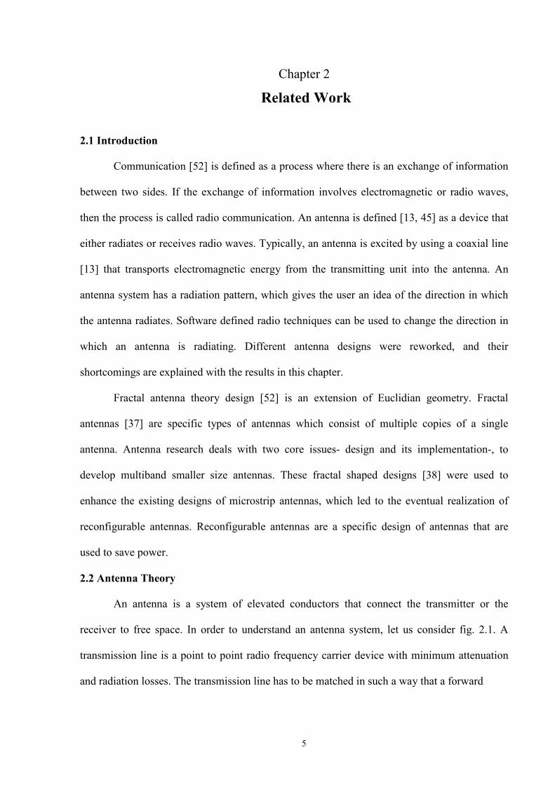
An antenna is a system of elevated conductors that connect the transmitter or the
receiver to free space. In order to understand an antenna system, let us consider fig. 2.1. A
transmission line is a point to point radio frequency carrier device with minimum attenuation
and radiation losses. The transmission line has to be matched in such a way that a forward
6
moving wave travels only in the forward direction. A dipole antenna is a specific type of
Fig. 2.1 Transmission System
antenna in which the two ends are at equal potential relative to the mid-point, and the antenna
itself is fed at the centre by the transmission line. The parameters typically discussed in this
chapter include:
• Input Return Loss
• Antenna Far Field
• Directivity Pattern
• Resonating Frequency
• VSWR
2.3 Types of Antennas
The various types of antennas that were studied are described below.
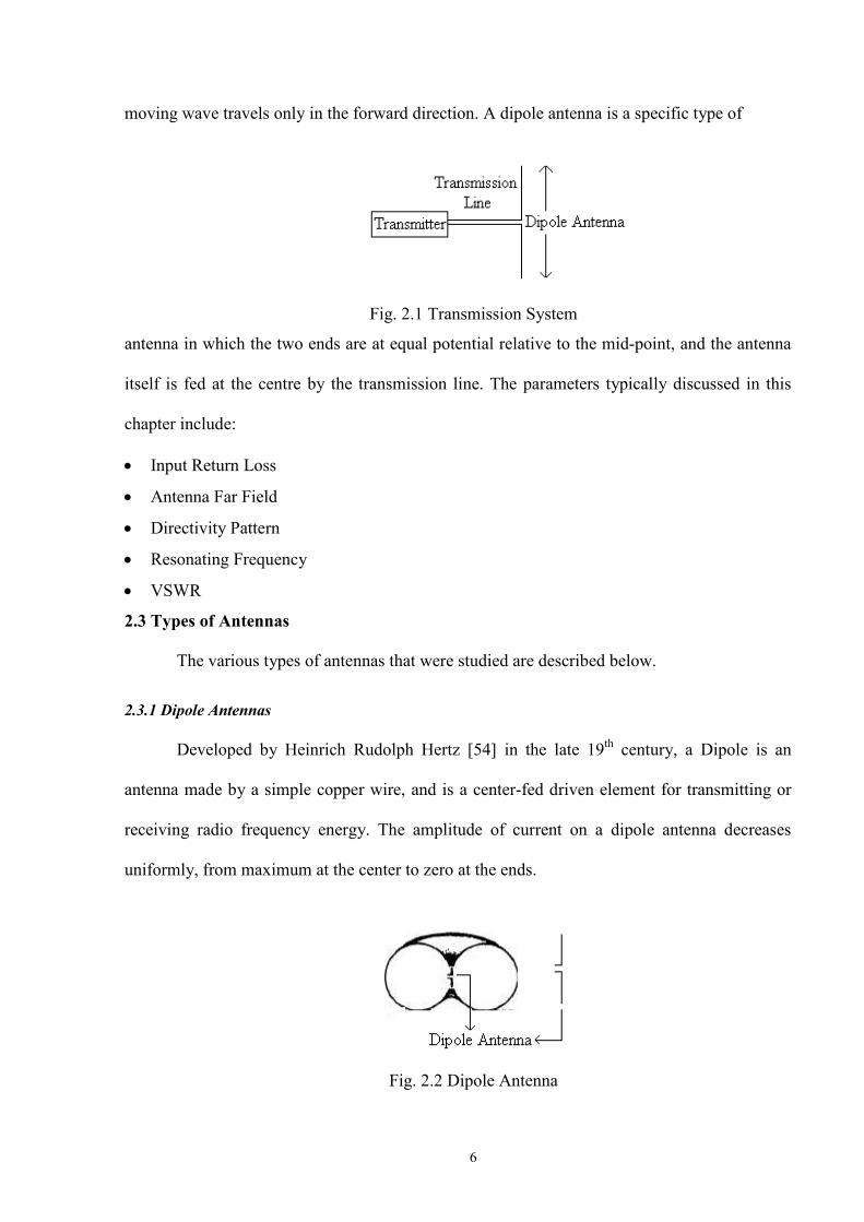
2.3.1 Dipole Antennas
Developed by Heinrich Rudolph Hertz [54] in the late 19th century, a Dipole is an
antenna made by a simple copper wire, and is a center-fed driven element for transmitting or
receiving radio frequency energy. The amplitude of current on a dipole antenna decreases
uniformly, from maximum at the center to zero at the ends.
Fig. 2.2 Dipole Antenna
7
A dipole shown in fig. 2.2 radiates on both sides and can have any length, but usually it
is just under ½ wavelengths long. A dipole which is ½ wavelengths long is known as a
resonant, or a half wave dipole, and has input impedance that is purely resistive and lies
between 30 and 80 ohms. A half wave dipole provides a good match to 50 ohms coaxial cables,
as well as to transmitters and receivers which have 50 ohm output and input impedances. The
length of a dipole can be approximately determined from the following formula
Where is the length in feet, and is the frequency in MHz
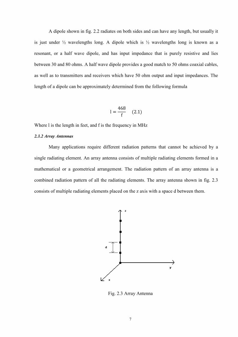
2.3.2 Array Antennas
Many applications require different radiation patterns that cannot be achieved by a
single radiating element. An array antenna consists of multiple radiating elements formed in a
mathematical or a geometrical arrangement. The radiation pattern of an array antenna is a
combined radiation pattern of all the radiating elements. The array antenna shown in fig. 2.3
consists of multiple radiating elements placed on the z axis with a space d between them.
Fig. 2.3 Array Antenna

8
2.3.3 Fractal Antennas
Fractal electrodynamics [37] is a field of electrodynamics which combines fractal
geometry and electromagnetic theory to solve the problems of radiation, propagation, and
scattering in antennas. A fractal is a rough or fragmented geometric shape [54] which can be
subdivided in parts, each of which is a reduced-size copy of the whole. Fractals are generally
self-similar and independent of scale. A case of a log periodic antenna [37] folding inwards is
considered to be a fractal antenna. A simple example of a fractal antenna could be an ordinary
wire antenna shaped into many similar shapes. The size of the antenna would thus be very
large. Since each shape of the fractal antenna is analyzed as a conjunction of capacitors and
inductors, the fractal antenna would thus be a combination of multiple capacitors and
inductors. It should be understood that the number of resonances would not depend on the size
of the radiating structure, but on the combination of capacitors and inductors being used.
Fig. 2.4 Fractal Antenna
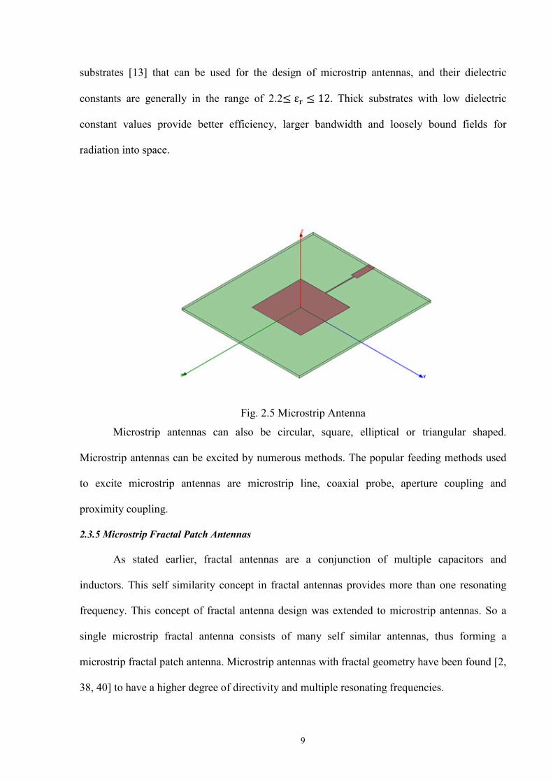
2.3.4 Microstrip Antennas
Microstrip antennas, also called patch antennas, consist of a metallic strip placed on a
small fraction of a wavelength on a substrate situated on a ground plane. There are many
9
substrates [13] that can be used for the design of microstrip antennas, and their dielectric
constants are generally in the range of 2.2 Thick substrates with low dielectric
constant values provide better efficiency, larger bandwidth and loosely bound fields for
radiation into space.
Fig. 2.5 Microstrip Antenna
Microstrip antennas can also be circular, square, elliptical or triangular shaped.
Microstrip antennas can be excited by numerous methods. The popular feeding methods used
to excite microstrip antennas are microstrip line, coaxial probe, aperture coupling and
proximity coupling.
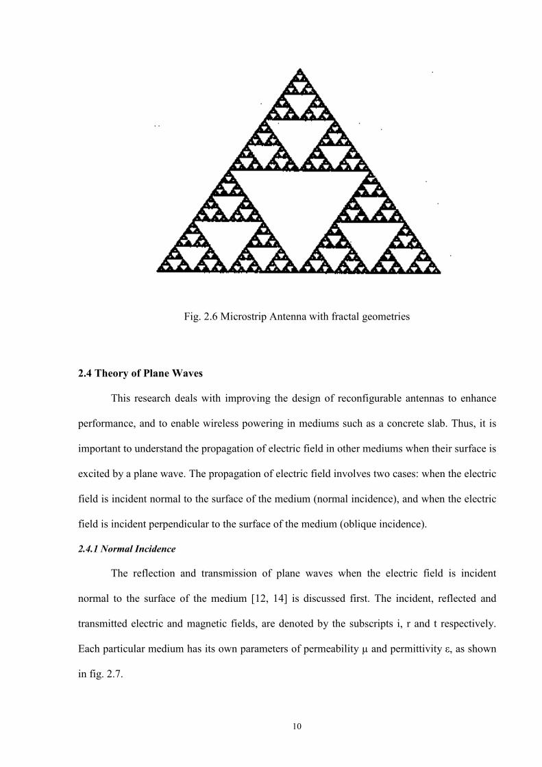
2.3.5 Microstrip Fractal Patch Antennas
As stated earlier, fractal antennas are a conjunction of multiple capacitors and
inductors. This self similarity concept in fractal antennas provides more than one resonating
frequency. This concept of fractal antenna design was extended to microstrip antennas. So a
single microstrip fractal antenna consists of many self similar antennas, thus forming a
microstrip fractal patch antenna. Microstrip antennas with fractal geometry have been found [2,
38, 40] to have a higher degree of directivity and multiple resonating frequencies.
10
Fig. 2.6 Microstrip Antenna with fractal geometries
2.4 Theory of Plane Waves
This research deals with improving the design of reconfigurable antennas to enhance
performance, and to enable wireless powering in mediums such as a concrete slab. Thus, it is
important to understand the propagation of electric field in other mediums when their surface is
excited by a plane wave. The propagation of electric field involves two cases: when the electric
field is incident normal to the surface of the medium (normal incidence), and when the electric
field is incident perpendicular to the surface of the medium (oblique incidence).
2.4.1 Normal Incidence
The reflection and transmission of plane waves when the electric field is incident
normal to the surface of the medium [12, 14] is discussed first. The incident, reflected and
transmitted electric and magnetic fields, are denoted by the subscripts i, r and t respectively.
Each particular medium has its own parameters of permeability µ and permittivity ε, as shown
in fig. 2.7.
11
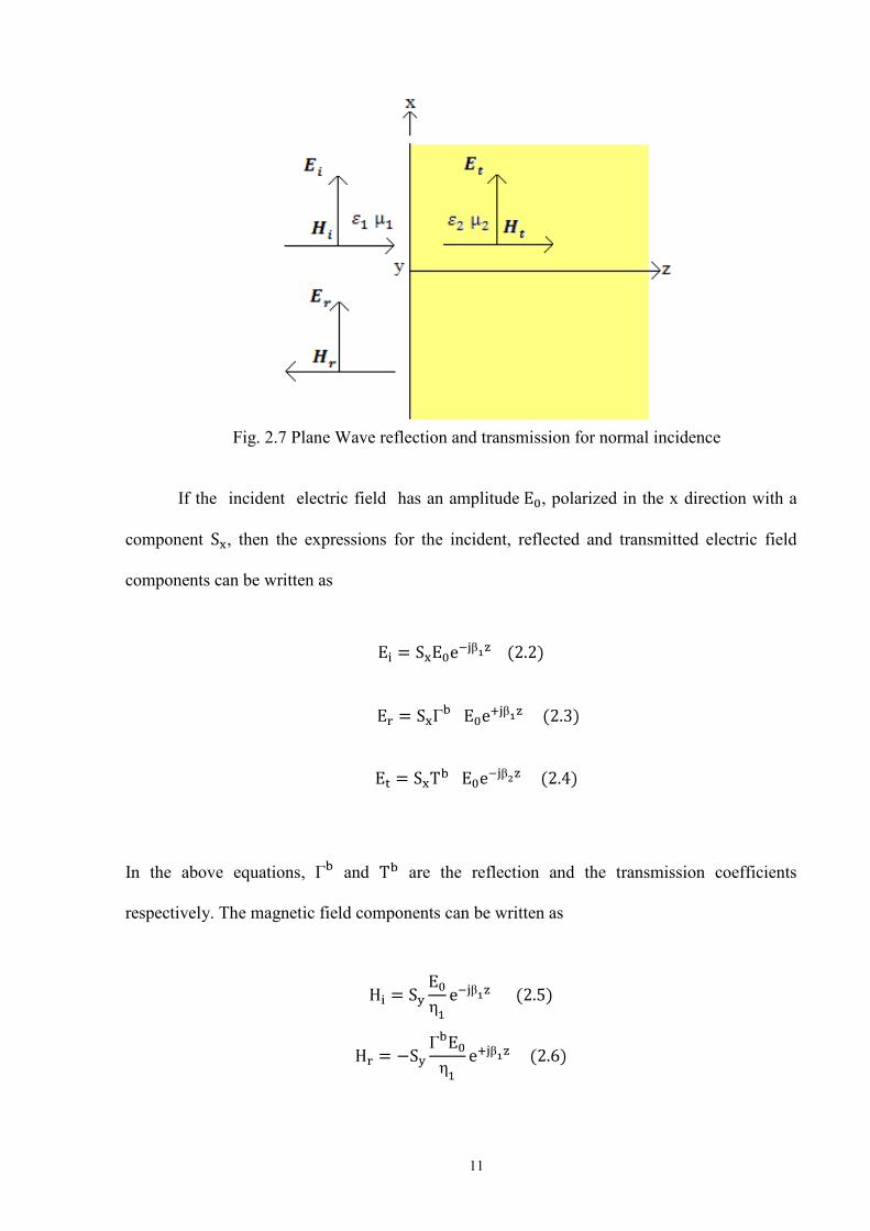
Fig. 2.7 Plane Wave reflection and transmission for normal incidence
If the incident electric field has an amplitude , polarized in the x direction with a
component , then the expressions for the incident, reflected and transmitted electric field
components can be written as
In the above equations, and are the reflection and the transmission coefficients
respectively. The magnetic field components can be written as
12
Finally, the equations for the reflection and transmission coefficients can be written as
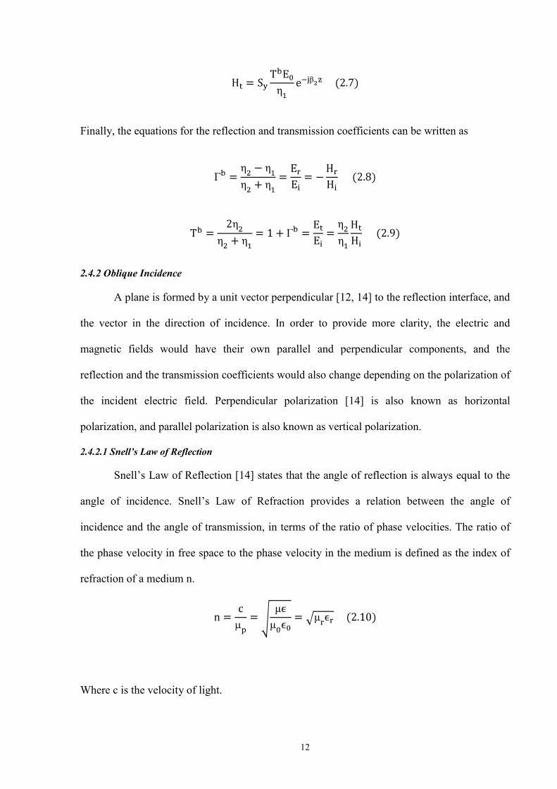
2.4.2 Oblique Incidence
A plane is formed by a unit vector perpendicular [12, 14] to the reflection interface, and
the vector in the direction of incidence. In order to provide more clarity, the electric and
magnetic fields would have their own parallel and perpendicular components, and the
reflection and the transmission coefficients would also change depending on the polarization of
the incident electric field. Perpendicular polarization [14] is also known as horizontal
polarization, and parallel polarization is also known as vertical polarization.
2.4.2.1 Snell’s Law of Reflection
Snell’s Law of Reflection [14] states that the angle of reflection is always equal to the
angle of incidence. Snell’s Law of Refraction provides a relation between the angle of
incidence and the angle of transmission, in terms of the ratio of phase velocities. The ratio of
the phase velocity in free space to the phase velocity in the medium is defined as the index of
refraction of a medium n.
Where c is the velocity of light.

13
Snell’s law of Refraction can be written as
The subscript r denotes the relative permeability and relative permittivity.
For nonmagnetic materials, , so in this case
where is the intrinsic impedance of a dielectric medium.
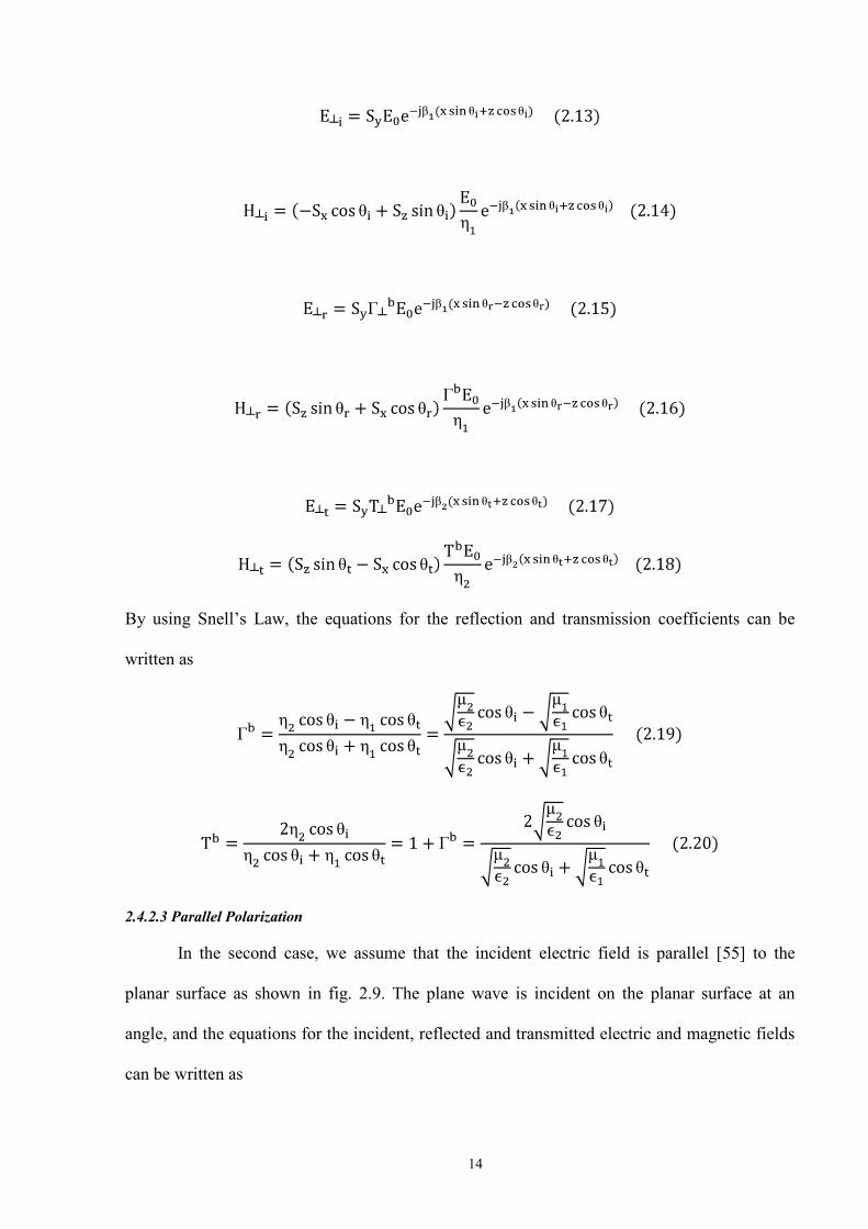
2.4.2.2 Perpendicular Polarization
In the first case, we assume that the incident electric field is perpendicular [55] to the
planar surface as shown in fig. 2.8. The plane wave is incident on the planar surface at an
angle, and the equations for the incident, reflected and transmitted electric and magnetic fields
can be written as
Fig. 2.8 Plane Wave reflection and transmission for perpendicular polarization
14
By using Snell’s Law, the equations for the reflection and transmission coefficients can be
written as
2.4.2.3 Parallel Polarization
In the second case, we assume that the incident electric field is parallel [55] to the
planar surface as shown in fig. 2.9. The plane wave is incident on the planar surface at an
angle, and the equations for the incident, reflected and transmitted electric and magnetic fields
can be written as

15
Fig. 2.9 Plane Wave reflection and transmission for parallel polarization

16
By using Snell’s Law the equations for the reflection and transmission coefficient can be
written as
2.4.2.4 Brewster’s Angle
Brewster’s angle [14] is defined as the incidence angle , at which the Fresnel
reflection coefficient .
2.4.2.4.1 Perpendicular Polarization
For Perpendicular Polarization, the Brewster’s angle can be written as
does not exist for nonmagnetic materials, that is when .
2.4.2.4.2 Parallel Polarization
For parallel polarization, Brewster’s angle can be written as
For nonmagnetic materials, Brewster’s angle can be written as

17
For ,
2.5 Permittivity of Concrete
The permittivity of a concrete slab [7] has been modeled assuming that it is a lossy
dielectric, and that a slab has a real part and an imaginary part. The permittivity of a concrete
slab can be written as
is the real part of complex permittivity of a concrete slab and is the imaginary part of
permittivity of a concrete slab. By modeling a concrete slab as a Debye material [7], its
frequency dependent complex relative permittivity obeys the following
Table .1 Fitted Parameters for the Concrete Samples [7]
Moisture Content
0.2% 12%
4.8± 0.002 12.84± 0.03
4.507± 0.002 7.42± 0.02
0.82± 0.01 0.611± 0.006
6.06 0.06
20.6 0.2
Where is the difference between the values of the real part of the complex
relative permittivity, and τ is the relaxation time. The above equation represents the first model
of relative permittivity of a concrete slab. In order to take into account the additional energy
18
0 1 2 3 4 5 6 7 8 9 10
x 108
0
2
4
6
8
10
12
14
Frequency (Hz)
Rel
ativ
e P
erm
ittiv
ity o
f Con
cret
e
Relative Permittivity of Concrete for a 0.2 and 12% moisture content
IMAG(Er)-12%REAL(Er)-12%
0 1 2 3 4 5 6 7 8 9 10
x 108
0
0.5
1
1.5
2
2.5
3
3.5
4
4.5
5
Frequency (Hz)
Rel
ativ
e P
erm
ittiv
ity o
f Con
cret
e
Relative Permittivity of Concrete for a 0.2 moisture content
IMAG(Er)-0.2%REAL(Er)-0.2%
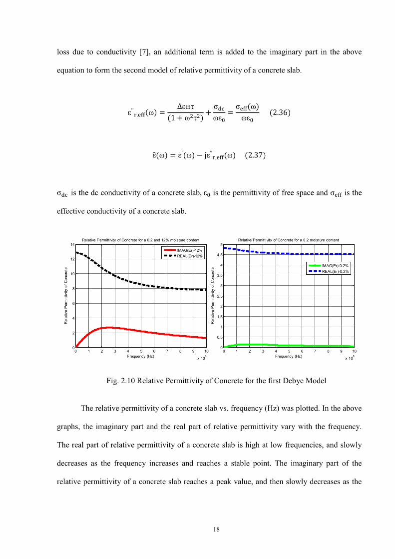
loss due to conductivity [7], an additional term is added to the imaginary part in the above
equation to form the second model of relative permittivity of a concrete slab.
is the dc conductivity of a concrete slab, is the permittivity of free space and is the
effective conductivity of a concrete slab.
Fig. 2.10 Relative Permittivity of Concrete for the first Debye Model
The relative permittivity of a concrete slab vs. frequency (Hz) was plotted. In the above
graphs, the imaginary part and the real part of relative permittivity vary with the frequency.
The real part of relative permittivity of a concrete slab is high at low frequencies, and slowly
decreases as the frequency increases and reaches a stable point. The imaginary part of the
relative permittivity of a concrete slab reaches a peak value, and then slowly decreases as the
19
0 0.2 0.4 0.6 0.8 1 1.2 1.4 1.6 1.8 2
x 109
0
1
2
3
4
5
6
Frequency (Hz)
Com
plex
par
t of R
elat
ive
Per
mitt
ivity
of C
oncr
ete
Complex part of Relative Permittivity of Concrete
IMAG(Er)-12%IMAG(Er)-0.2%
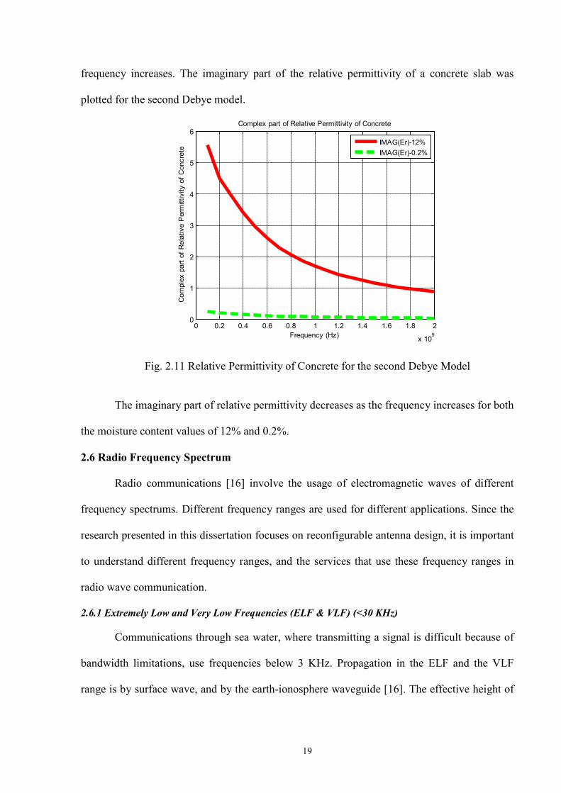
frequency increases. The imaginary part of the relative permittivity of a concrete slab was
plotted for the second Debye model.
Fig. 2.11 Relative Permittivity of Concrete for the second Debye Model
The imaginary part of relative permittivity decreases as the frequency increases for both
the moisture content values of 12% and 0.2%.
2.6 Radio Frequency Spectrum
Radio communications [16] involve the usage of electromagnetic waves of different
frequency spectrums. Different frequency ranges are used for different applications. Since the
research presented in this dissertation focuses on reconfigurable antenna design, it is important
to understand different frequency ranges, and the services that use these frequency ranges in
radio wave communication.
2.6.1 Extremely Low and Very Low Frequencies (ELF & VLF) (<30 KHz)
Communications through sea water, where transmitting a signal is difficult because of
bandwidth limitations, use frequencies below 3 KHz. Propagation in the ELF and the VLF
range is by surface wave, and by the earth-ionosphere waveguide [16]. The effective height of
20
the ionosphere in the ELF band is approximately 90 Km. Submarines that communicate with
land bases through ocean water use the ELF band. Huge land based transmitting antennas are
required to transmit the signal, and relatively low data rates are possible. Sea water [16] is
highly conductive, and the attenuation in one skin depth of sea water or any other dielectric is
8.86 dB. Since the attenuation in sea water is very high, the longest wavelengths have to be
used for the attenuation to be kept to usable values. The propagation constant in sea water
is complex, has high conductivity losses, and is given by
2.6.2 Ionosphere
The ionosphere is the upper region of the atmosphere [16], approximately 50 Km above
the surface of the earth, where atmospheric gasses have been ionized by solar flux and cosmic
radiation. Ionization occurs because of rare atmospheric gases and radiation caused by
atmospheric attenuation that exists at the highest and the lowest altitudes of the ionosphere
respectively. Up to 80 Km altitude [16], the earth’s dry atmosphere is well mixed. Dissociation
of ions varies with altitude above 80 km of the earth’s surface because of varying densities of
ionized gases.
2.6.3 Low and Medium Frequencies (LF & MF) (30 KHz to 3 MHz)
Marine and aeronautical radio navigations [16] use the LF band from 30 KHz to 500
KHz. Atmospheric noise is a major factor in the LF and MF frequency bands. Amplitude
modulation (AM) uses the band segment between 535 KHz and 1705 KHz. Ground wave
propagation [16] utilizes the MF band from 300 KHz to 3 MHz. Ionospheric absorption is high
during the daytime in the LF and the MF bands.

21
2.6.4 High Frequencies (HF) (3 to 30 MHz)
Worldwide radio communications [16] that are designed on the basis of ionospheric reflections
use the HF band. Ionospheric transmission provides a channel of small attenuation. Narrow
band applications [16] of bandwidth less than 3 KHz use the HF band.
2.6.5 Very High Frequencies and Ultrahigh Frequencies (VHF & UHF) (30 MHz to 3 GHz)
Mobile communications services (MCS), personal communication services (PCS), and
satellite-based services utilize the VHF and the UHF frequency ranges. Geomagnetic activity
[16] causes significant ionospheric reflections from 50 to 60 MHz. Cellular telephone services
[16] use the frequency range between 800 and 900 MHz. Paging and messaging use the 900
MHz band, and the PCS uses the bands from 1700 to 2200 MHz. Personal and local area
networks use frequencies above 2400 MHz.
2.6.6 Above Ultrahigh Frequencies (Above 3 GHz)
Satellite-based communications [16] use the UHF bands. Propagation is generally Line
of Sight with occasional tropospheric scattering. Propagation in satellite systems [16] is done
through the ionosphere, and signal polarization is rotated because of the combined effect of the
earth’s magnetic field and the free ion concentration.
2.6.7 UWB Systems
FCC regulations in the United States permit [16] Ultra Wideband (UWB)
communications in the 3.1 to 10.6 GHz frequency spectrum.
2.7 Wireless Powering
During the transmission of radio frequency energy from one antenna to another, the
electric field is either incident parallel to the receiving antenna, or is incident at an angle. If the
electric field is parallel to the receiving antenna, it receives maximum voltage supply, and if
the electric field [16] is incident at an angle, it receives voltage as a function of the angle at
which the electric field is incident on it.

22
Table . 2 Radio Frequency Spectrum [16
Frequency
]
Band Characteristics Services
3 Hz-30 KHz ELF, VLF High atmospheric noise, inefficient antennas.
Submarine, navigation, sonar.
30-300 KHz LF High atmospheric noise
Long-range navigation beacons.
0.3-3 MHz MF High atmospheric noise, good ground wave propagation.
Navigation, maritime communication, AM broadcasting.
3-30 MHz HF Moderate atmospheric noise, ionospheric reflections that provide long distance links, affected by solar flux
International Shortwave broadcasting , ship-to-shore, t Telephone, telegraphy , long range aircraft communication, amateur radio.
30-300 MHz VHF Ionospheric reflections, line of sight propagation
Mobile, FM broadcasting, air traffic control, television, radio navigation aids.
0.3-3 GHz UHF Line of sight propagations, efficient portable antennas.
Television, radar, Global Positioning Systems (GPS), PCS, mobile phones, wireless local area networking, land-mobile communications, satellite communications
3-30 GHz SHF Line of sight propagation
UWB, fixed broadband, 3G PCS, Microwave links, land-mobile communication, wireless LANs and and PANs, fixed broadband, 3G PCS.
30-300 GHz EHF Line of sight propagation, atmospheric absorption
Radar, military and secure,Communications, satellite links, mm-wave personal-area networking.
300- GHz IR-optics Line of sight propagation, atmospheric absorption
Optical communications, fiber optical links.

23
Fig. 2.12 Wireless Power Transmission
2.7.1 Current Consumption of Typical Sensors
A temperature sensor [9] consumes 300 μA (μ=Micro=10 6− ) for 50μSec for a stable
reading every five seconds, and a humidity sensor consumes 2.8mA for 150 msec for a stable
reading every thirty seconds. The radio frequency energy incident on the receiving antenna has
to be converted to electrical energy [8] to enable wireless powering.
2.8 Antenna Simulation Parameters
In order to understand the performance of an antenna, a detailed understanding of the
simulation parameters of an antenna is necessary.
2.8.1 S- Parameters
When an antenna is excited at one end, the measurements of reflected current or voltage
reveals the frequencies at which the antenna works best. This measurement can be done using
the S-parameters. The S-parameter matrix for the 2-port network generates higher order
matrices for larger networks [56, 57]. In this case, the relationship between the reflected and
the incident power waves, as well as the S-parameter matrix is given by

24
If port 2 is terminated in a load identical to the system impedance then, by the
maximum power transfer theorem, will be totally absorbed making equal to zero, and vice
versa. Thus, the above two equations are reduced to
Each parameter can be defined as:
• is the input port voltage reflection coefficient
• is the reverse voltage gain
• is the forward voltage gain
• is the output port voltage reflection coefficient
The frequency at which is least is the resonating frequency. It is the frequency at which the
antenna works best.
2.8.2 Directivity
Directivity of an antenna [13] is defined as the ratio of radiation intensity in a given
direction from the antenna, to the average radiation intensity in all other directions.
25
If the direction is not specified, then the direction of maximum radiation intensity is
used and is expressed as
D= directivity (no dimensions)
= maximum directivity (no dimensions)
U= radiation intensity (W/unit solid angle)
= maximum radiation intensity (W/unit solid angle)
= radiation intensity of isotropic source
= total radiated power (W)
2.8.3 VSWR
In a transmission line, a standing wave ratio (SWR) [58] is the ratio of the amplitude of
a partial standing wave at an antinode (maximum), to the amplitude at an adjacent node
(minimum). Generally, the SWR is defined as a voltage ratio called the voltage standing wave
ratio (VSWR). A VSWR value 1.2:1 denotes a maximum standing wave amplitude, which is
1.2 times greater than the minimum standing wave value. The VSWR for an antenna has to be
lower than 2.
2.9 Reconfigurable Antennas
A reconfigurable antenna consists of switches and radiating parts. The Reconfigurable
Sierpinski Gasket antenna (RSGA) [2, 36] shown in fig. 2.13 consists of three similar
triangular radiating parts. The top triangle is connected to the bottom two triangles by switches,
as shown in fig. 2.13. The switches can be turned on or off, and the size of the antenna as well
as radiation patterns can be varied. The Reconfigurable Sierpinski Gasket antenna shown in

26
Fig. 2.13 Reconfigurable Sierpinski Gasket Antenna
fig. 2.13, consists of five feeding points (the three free vertices of the three triangles and the
two switches). This antenna can be used over a range of frequencies from 1 to 20 GHz, over
which it resonates at two frequencies.
2.9.1 Reconfigurable Sierpinski Gasket Antenna
Two important parameters that constitute into forming a Sierpinski Gasket Antenna are
the base b and the height h. To extend the concept of self similarity to antennas, the right half
plane of a right angled triangle is joined to the left half plane of another right angled
triangle, to form one triangle.
Fig. 2.14 Reconfigurable Sierpinski Gasket Antenna with iterations
If one iteration is added to the triangle already formed, then two more triangles are
added to the existing geometry [2, 36]. It is important to understand that the parameters h and s
27
become half with every iteration, which is an addition of a new triangle, as is shown in fig.
2.14. The radiation pattern of an antenna is related to the distributions of currents on its
surface, so if the amount of current flowing to a particular part of the antenna is varied at
different frequencies, then its radiation pattern varies. Thus the characteristics of self similarity
of a fractal antenna are used in the design [2, 18, 38] as the fractal antennas radiate at different
frequencies.
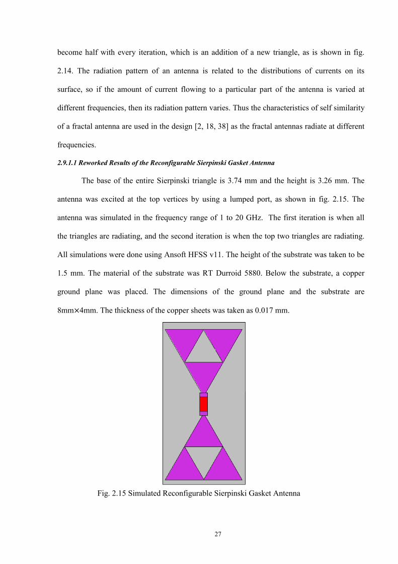
2.9.1.1 Reworked Results of the Reconfigurable Sierpinski Gasket Antenna
The base of the entire Sierpinski triangle is 3.74 mm and the height is 3.26 mm. The
antenna was excited at the top vertices by using a lumped port, as shown in fig. 2.15. The
antenna was simulated in the frequency range of 1 to 20 GHz. The first iteration is when all
the triangles are radiating, and the second iteration is when the top two triangles are radiating.
All simulations were done using Ansoft HFSS v11. The height of the substrate was taken to be
1.5 mm. The material of the substrate was RT Durroid 5880. Below the substrate, a copper
ground plane was placed. The dimensions of the ground plane and the substrate are
8mm 4mm. The thickness of the copper sheets was taken as 0.017 mm.
Fig. 2.15 Simulated Reconfigurable Sierpinski Gasket Antenna
28
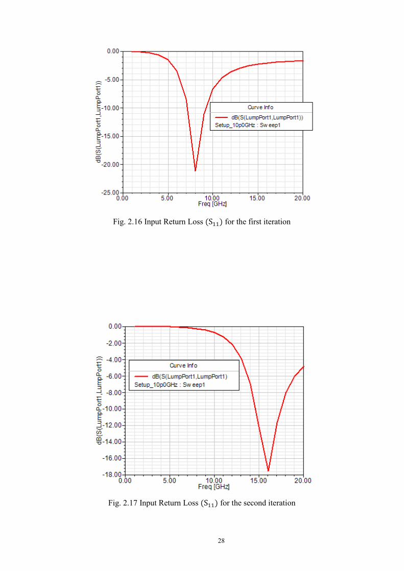
Fig. 2.16 Input Return Loss for the first iteration
Fig. 2.17 Input Return Loss for the second iteration

29
Fig. 2.18 VSWR for the first iteration
Fig. 2.19 VSWR for the second iteration
30
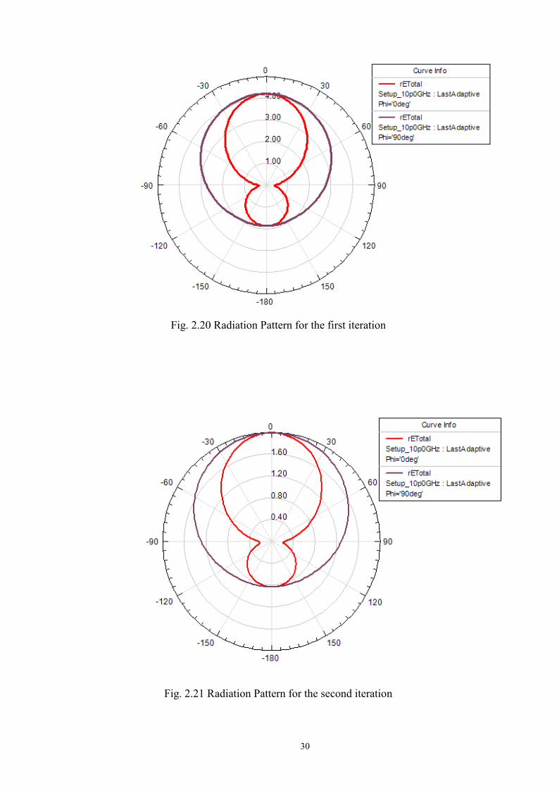
Fig. 2.20 Radiation Pattern for the first iteration
Fig. 2.21 Radiation Pattern for the second iteration
31
2.9.1.2 Data Analysis and Shortcomings
Input Return Loss from fig. 2.16 for the first iteration shows that there is a
resonating frequency at 8 GHz. Input Return Loss from fig. 2.17 for the second iteration
shows that there is a resonating frequency at 16 GHz. VSWR for the first and the second
iteration shows a very high value until 8GHz. The radiation patterns show an omnidirectional
radiation pattern for this antenna. There is no justifiable mathematical design equation which
can be used by an engineer to design this antenna for a specific bandwidth. The input return
loss for each iteration reveals only one resonating frequency. If more iterations are to be added,
then the design becomes complex.
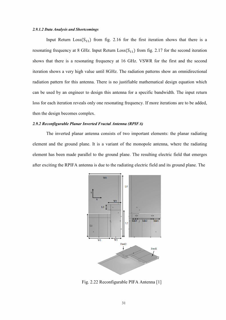
2.9.2 Reconfigurable Planar Inverted Fractal Antenna (RPIFA)
The inverted planar antenna consists of two important elements: the planar radiating
element and the ground plane. It is a variant of the monopole antenna, where the radiating
element has been made parallel to the ground plane. The resulting electric field that emerges
after exciting the RPIFA antenna is due to the radiating electric field and its ground plane. The
Fig. 2.22 Reconfigurable PIFA Antenna [1]

32
RPIFA antenna is highly favored for its smaller size and lower profile, and is [1] widely
preferred in wireless devices. PIFA antennas have many additional advantages, such as
being cost effective to manufacture, very easy to fabricate, having higher bandwidth and
favorable electrical performance.
2.9.2.1 Reworked Results of the Reconfigurable Planar Inverted Fractal Antenna (RPIFA)
A copper ground plane has been used for the RPIFA. The switches for this antenna [1]
have been simulated as perfect electric conducting cylinders. The feeds were simulated as
perfect electric conducting cylinders, which were excited by using lumped ports. The
dimensions of the ground plane [1] are W0=60 x L0=114 mm. At a height of 4 mm above the
ground plane is a metallic patch of dimensions L1=45 x W1=40 mm. At the end of this patch is
a slit divided into three parts, each of which has a width of 4 mm. The length of the three parts
are lslit1=15 mm, lslit2=15 mm and lslit3=9 mm respectively. These three parts are connected
by switches. The three slits were modeled as boxes of copper. The dimensions of the second L
shaped patch element are L2=50 mm x W2=19 mm, and L3=10 mm x W3=25 mm. A total of
14 switches connect the radiating elements to the ground plane. The thickness of the copper
sheets was taken as 0.017 mm.
Fig. 2.23 Input Return Loss ( ) at lumped port 1
33
Fig. 2.24 Input Return Loss ( ) at lumped port 2
Fig. 2.25 VSWR at lumped port 1

34
Fig. 2.26 VSWR at lumped port 2
Fig. 2.27 Radiation Pattern for the Reconfigurable PIFA Antenna
35
2.9.2.2 Data Analysis and Shortcomings
This antenna was simulated in the original paper [1] using a matrix along with signal
processing techniques. Unfortunately, the simulation techniques used [1] were not described
clearly. Though the results could change with the size in the lumped port, they are
discouraging. The input return losses ( ) hardly show any resonating frequencies, so the
antenna is hardly radiating any power. The VSWR for this antenna is also extremely high. A
major setback for this antenna is that reconfigurability is not properly defined. This antenna has
only one iteration with or without the presence of switches. Once again, there is no design
equation to help the designer to design this antenna for a specific bandwidth.
2.10 Summary
The RSGA antenna works between the frequency range of 3 GHz to 30 GHz. It can be
used for UWB and fixed broadband applications. Research has to be done to check if wireless
powering in a concrete slab is possible. Research has to also be done to see if reconfigurable
antennas can facilitate wireless powering. Finally, a new reconfigurable antenna has to be
developed which is easy to design, has mathematical design equations and has good
performance. The reconfigurable antennas described in earlier sections have a lot of
disadvantages, and they need to be rectified. A concrete surface needs to be recreated in Ansoft
HFSS.
36
Chapter 3
Wireless Powering in a Concrete Slab
3.1 Introduction
This chapter deals with powering a sensor buried inside a concrete slab at a certain
depth by delivering power to the load resistance of the sensor antenna. Antennas inside a
concrete slab should be able to receive power from the electromagnetic energy that penetrates
the concrete slab. If an antenna outside a concrete slab is radiating power, then that power
penetrates the surface of the concrete slab and decays according to the parameters of a concrete
slab. So researching the parameters of a concrete slab, as well as investigating the attenuation
of the electric field as the depth increases is very important to determine the power received by
an antenna. This chapter also investigates which antenna is the best to receive maximum power
inside a concrete slab. As stated earlier in section 2.5, a concrete slab is a penetrable material
which requires a detailed research and understanding into its electrical properties, if it has to be
used in any application.
The theoretical Debye model [7] has been used to understand the behavior of a concrete
slab with respect to frequency, moisture content and other factors. In the analyses, [7] a
concrete slab has been treated as a dielectric material having both the real and complex part of
permittivity and effective conductivity, which are dependent on frequency. Measurements have
been performed to understand the frequency-dependent nature of the electrical properties of a
concrete slab.
When a plane wave is incident on the surface of a concrete slab, some part of it is
reflected back and the remaining passes into the slab. The power that the antenna receives
depends on the polarization of the incident plane wave, as well as the attenuation due to
propagation through a concrete slab. If the polarization of the incident waves and the angle of
37
incidence determines the power received, then those factors become very important and have
to be taken into consideration.
3.2 Uniform Plane Waves in a Concrete Medium-Principal Axis and Oblique Angle
Let us consider that a uniform plane wave is incident on a concrete slab. As of now, the
direction and orientation of the electric field is not considered for simplicity. Since the wave is
travelling from free space into a concrete slab interface, we assume that the incident electric
field has a certain magnitude. This magnitude of the electric field decays with the attenuation
of a concrete slab as well as the depth. Let us suppose that the incident electric field is given by
The attenuation in a concrete slab was calculated using the equation
Fig. 3.1 Incident Electric Field on a Concrete Slab
38
3.2.1 Direction of Propagation of a Uniform Plane Wave
In the above figure, the concrete slab is placed along the z-axis. If the electric field has
an x component, then it would be interpreted as the electric field is incident perpendicular to
the concrete slab (Normal Incidence), and if the electric field has a y component, then it would
be interpreted as the incident electric field is polarized perpendicular to the concrete slab.
Lastly, if the electric field has an x component and a z component, then it would be interpreted
as the incident electric field is polarized parallel to the concrete slab. In fig. 3.1, the electric
field has parallel polarization, since it has an x component as well as a z component. If is the
incident electric field on a concrete slab, and is the transmitted electric field through a
concrete slab, then is the electric field reflected of the surface of the slab. So the transmitted
and incident electric fields for different polarizations can be written as
Where T is the transmission coefficient and z is the depth in a concrete slab. In the above
expressions, the phase constant of a concrete slab can also be considered in the exponential
term. The Intrinsic Impedance of a concrete slab is given by
are the permeability, permittivity and the effective conductivity of a concrete
slab respectively.

39
The Intrinsic impedance of free space is given by
are the intrinsic impedance, permittivity and permeability of free space. The transmission coefficients are given by
The Average Power Density of the electric field in free space is given by
The Average Power Density of the electric field in a concrete slab is given by
3.3 Power received by an antenna
Power received by an antenna when it is excited by a plane wave was calculated using
the equation
Power Received

40
E is the magnitude of electric field, T is the transmission coefficient, α is the attenuation, Z is
the depth in the concrete slab, is the length of the antenna and is the radiation resistance of
the antenna. Since the material used in this case is a concrete slab, it is essential to use
wavelength in a concrete slab rather than wavelength in free space. The wavelength in a
concrete slab is given by
The length of the dipole was taken to be for a linear dipole, and for a circular small loop the
effective length was used as
Where S is the area of the loop, and the factor is introduced because the open
circuit voltage is proportional to the magnetic flux density, which is normal to the plane of the
loop.
3.4 3D Fractal Hilbert Dipole Antennas
3D-fractal rectangular Koch dipole and 3D fractal Hilbert dipole antennas [60] exhibit
lower resonant frequencies and small volume occupations. For a self-similarity fractal, the
fractal dimension is given by the equation
Where N is the number of copies of the whole object, and γ is the scale factor for each copy.
A fractal-dimension is a measure of the space-filling properties and the complexity of
the fractal shape [61]. The two methods that can be used to enhance the design of a fractal
antenna are: designing miniaturized antenna elements and designing self similar antenna

41
elements. Designing miniaturized antenna elements leads to antennas which are more discrete
for the end user. Designing self similar multiband antennas allows a user to integrate several
aspects of a system into one antenna. Antennas designed using both these strategies can be
incorporated into highly advanced array and smart antenna designs. Usually, the fractal [62] is
restricted to 1D and 2D-space designs. The benefits of space-filling 3D-fractal antenna
elements [63] are limited, but it can be efficient in a self-similarity design.
Fig. 3.2 3D Fractal Hilbert Dipole Antenna [18]
The 3D fractal shaped wire antennas can give resonance compression and multiband behavior.
The length and the radiation resistance of the 3D fractal Hilbert antenna are given in the table
below.
Table . 3 Radiation resistance of a Hilbert 3D-2 Antenna [18]
Antenna Total wire length (cm)
at resonance (ohms)
Hilbert 3D-2 184.99 0.16
This antenna has a higher length and a lower radiation resistance. If the power received
equation (3.13) in section 3.3 is closely examined, it is observed that a higher length and a
lower radiation resistance enable an antenna to receive more power.
42
3.5 Power Accepted For a general radiating structure, the accepted power is given by
is the power accepted in watts and ds is the local port boundary unit. Real is the real part
of the complex number. E is the radiated electric field and is the complex conjugate of the
magnetic field H.
For the simple case of an antenna with one lossless port containing a single propagating
mode, the above expression reduces to
Where a is the complex modal excitation specified and is the single-entry generalized
scattering matrix.
3.6 Simulations and Results
The first question that has to be answered is whether wireless powering in a concrete
slab is possible. If assumed that there is a radiating structure in a concrete slab, then the amount
of power entering a concrete slab can be calculated from the incident power and the reflections
of a port. The thickness of the concrete slab was taken to be very thin (5 mm), and another
surface which was very close (5 mm from the surface of the concrete slice) was defined as a
wave port in Ansoft HFSS v8. The reflections of the surface of the concrete slab have to be
plotted to estimate approximately the power that penetrates a concrete slab. The electric field
inside the concrete slice for two extreme cases of moisture content (0.2% and 12%) was
simulated. The electric field values in the middle of the concrete slice were taken, and its

43
propagation through a concrete slab for a depth of 10 cms was calculated using the equation
(3.13) in section 3.3. The power received was plotted as a function of frequency for the values
of a Hilbert 3D-2 antenna in table . 3 using matlab.
Fig. 3.3 Input Return Loss S 11 (dB) of the surface of the concrete slice
Fig. 3.4 Electric Field inside a concrete slice (0.2 %) for the incident electric field having X and Y components

44
Fig. 3.5 Electric Field inside a concrete slice (12 %) for the incident electric field having X and Y components
Fig. 3.6 Electric Field inside a concrete slice (12 %) for the incident electric field having
an X component

45
0 0.2 0.4 0.6 0.8 1 1.2 1.4 1.6 1.8 2
x 109
0
1
2
3
4
5
6
7
8
9
Frequency(Hz)
Pow
er R
ecei
ved(
Wat
t)
Power Received by a Hilbert 3D-2 Antenna
Case 1Case 2Case 3Case 4
Fig. 3.7 Electric Field inside a concrete slice (0.2 %) for the incident electric field having an X component
The power received by an antenna vs. frequency was plotted neglecting the loss resistance of
the antenna for the above four cases, and the behavior was found to be approximately the same.
Table . 4 Magnitude of electric field for the four cases [3]
Fig. 3.8 Power received by a Hilbert 3D-2 Antenna for the First Debye model of relative permittivity of concrete
Moisture Content Component E
12 % X 1.2655 0.2 % X 1.3278 12 % X and Y 1.1082 0.2 % X and Y 1.6969
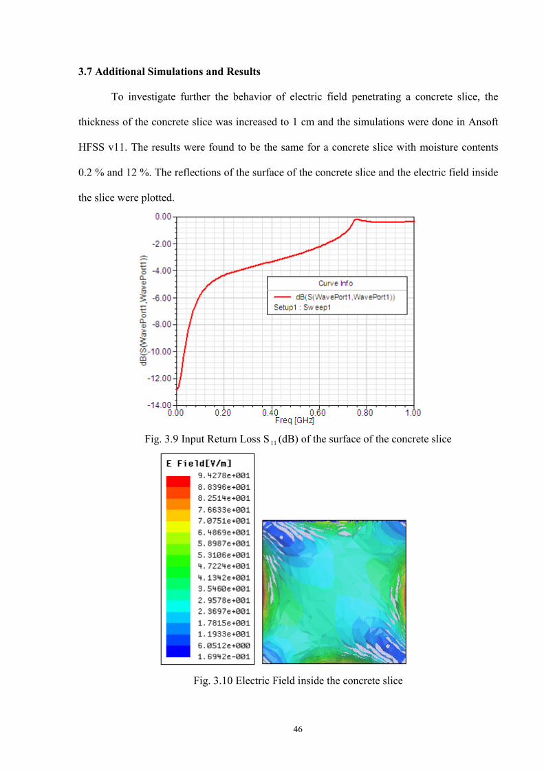
46
3.7 Additional Simulations and Results
To investigate further the behavior of electric field penetrating a concrete slice, the
thickness of the concrete slice was increased to 1 cm and the simulations were done in Ansoft
HFSS v11. The results were found to be the same for a concrete slice with moisture contents
0.2 % and 12 %. The reflections of the surface of the concrete slice and the electric field inside
the slice were plotted.
Fig. 3.9 Input Return Loss S 11 (dB) of the surface of the concrete slice
Fig. 3.10 Electric Field inside the concrete slice
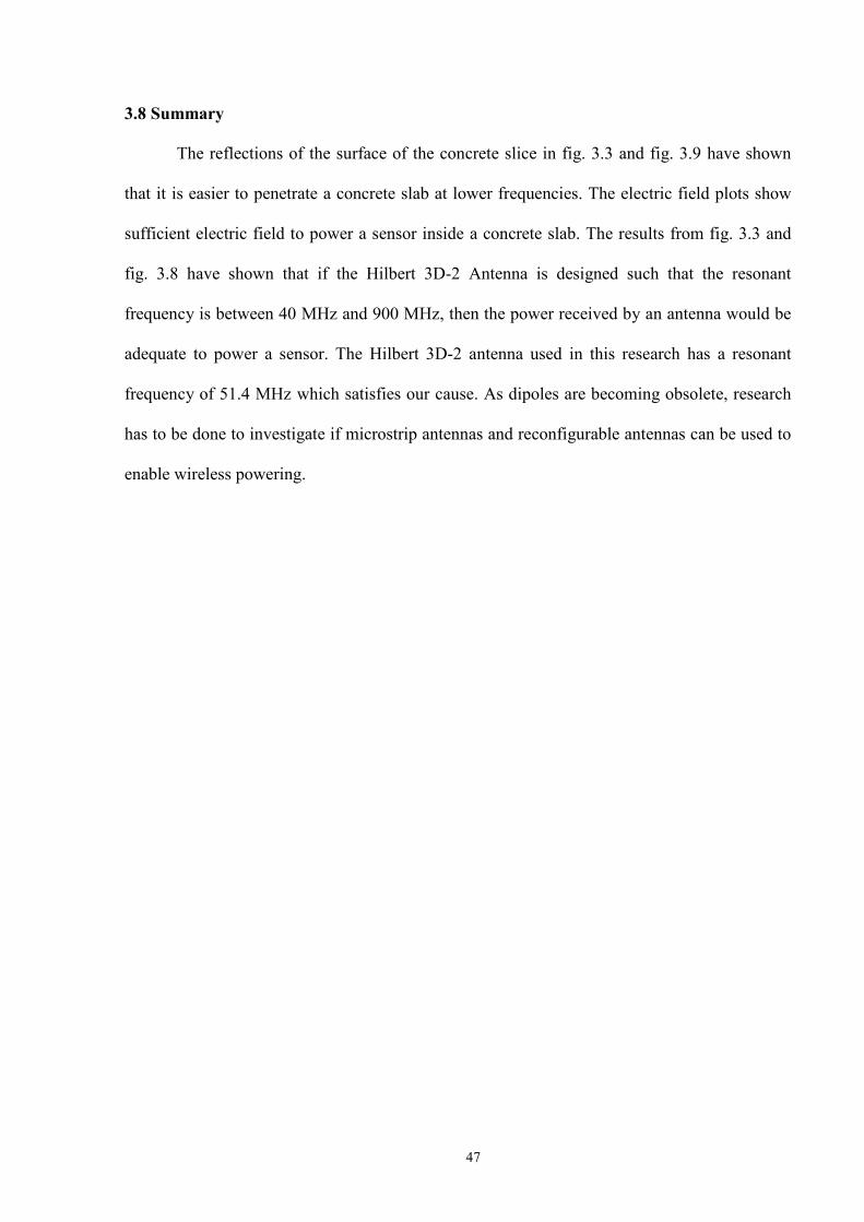
47
3.8 Summary
The reflections of the surface of the concrete slice in fig. 3.3 and fig. 3.9 have shown
that it is easier to penetrate a concrete slab at lower frequencies. The electric field plots show
sufficient electric field to power a sensor inside a concrete slab. The results from fig. 3.3 and
fig. 3.8 have shown that if the Hilbert 3D-2 Antenna is designed such that the resonant
frequency is between 40 MHz and 900 MHz, then the power received by an antenna would be
adequate to power a sensor. The Hilbert 3D-2 antenna used in this research has a resonant
frequency of 51.4 MHz which satisfies our cause. As dipoles are becoming obsolete, research
has to be done to investigate if microstrip antennas and reconfigurable antennas can be used to
enable wireless powering.
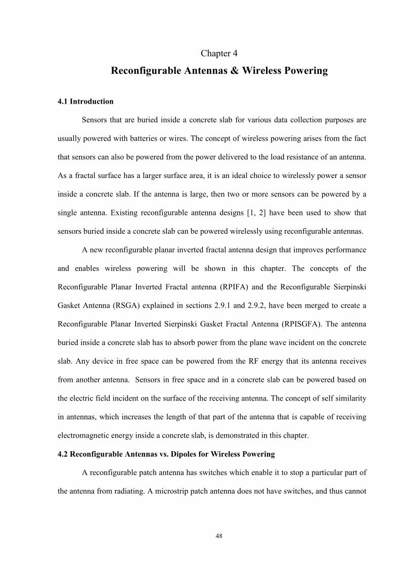
48
Chapter 4
Reconfigurable Antennas & Wireless Powering
4.1 Introduction
Sensors that are buried inside a concrete slab for various data collection purposes are
usually powered with batteries or wires. The concept of wireless powering arises from the fact
that sensors can also be powered from the power delivered to the load resistance of an antenna.
As a fractal surface has a larger surface area, it is an ideal choice to wirelessly power a sensor
inside a concrete slab. If the antenna is large, then two or more sensors can be powered by a
single antenna. Existing reconfigurable antenna designs [1, 2] have been used to show that
sensors buried inside a concrete slab can be powered wirelessly using reconfigurable antennas.
A new reconfigurable planar inverted fractal antenna design that improves performance
and enables wireless powering will be shown in this chapter. The concepts of the
Reconfigurable Planar Inverted Fractal antenna (RPIFA) and the Reconfigurable Sierpinski
Gasket Antenna (RSGA) explained in sections 2.9.1 and 2.9.2, have been merged to create a
Reconfigurable Planar Inverted Sierpinski Gasket Fractal Antenna (RPISGFA). The antenna
buried inside a concrete slab has to absorb power from the plane wave incident on the concrete
slab. Any device in free space can be powered from the RF energy that its antenna receives
from another antenna. Sensors in free space and in a concrete slab can be powered based on
the electric field incident on the surface of the receiving antenna. The concept of self similarity
in antennas, which increases the length of that part of the antenna that is capable of receiving
electromagnetic energy inside a concrete slab, is demonstrated in this chapter.
4.2 Reconfigurable Antennas vs. Dipoles for Wireless Powering
A reconfigurable patch antenna has switches which enable it to stop a particular part of
the antenna from radiating. A microstrip patch antenna does not have switches, and thus cannot

49
stop any part of itself from radiating. In the transmitting mode, the switches in a reconfigurable
patch antenna can be used as points where excitation can be applied. Similarly, in the receiving
mode, coaxial lines can be applied along with the switches to extract the received signal. So
when a reconfigurable patch antenna is compared to a microstrip patch antenna or a dipole
antenna, the first noticeable difference is that the reconfigurable patch antenna has more
excitation points.
As shown in fig. 2.12, when an antenna receives radio frequency energy from another
antenna, it has only one excitation point where the coaxial lines receive the power delivered to
the antenna. If the receiving antenna in fig. 2.12 is replaced with a reconfigurable antenna such
as the RPIFA shown in section 2.8.2, then multiple receiving coaxial lines can be used to
power multiple sensors. An antenna with one receiving coaxial line will have high reflections
as it is receiving the entire power incident on the antenna. The presence of multiple coaxial
lines will decrease the number of reflections when an antenna receives power from another
antenna. Thus, reconfigurable antennas can be used to enable wireless powering.
4.3 Reconfigurable Planar Inverted Sierpinski Gasket Fractal Antenna (RPISGFA)
In order to understand how the RPISGFA was created, it is necessary to understand the
Planar Inverted Fractal Antenna (PIFA), and the concept of self-similarity of a Sierpinski
Gasket Antenna. A Planar Inverted Fractal Antenna is considered to be an Inverted Fractal
antenna with the wire radiator element replaced by a planar radiating element to increase the
bandwidth. A Planar Inverted Fractal Antenna [64] consists of three elements: a rectangular
planar element located parallel and above a ground plane, a plate or a pin that short circuits the
radiating element and the ground plane, and an excitation mechanism for the radiating element.
The radiating element is placed parallel to and above the ground plane [64] to reduce
the height of the antenna while maintaining a resonant trace length. Capacitance introduced to
the input impedance of the antenna by the parallel section is compensated by implementing a

50
short circuiting pin. Excitation current to the radiating element is divided between the radiating
element and the ground plane. Since the excitation current is divided between the radiating
element and the ground plane, the resulting electromagnetic field of the antenna [64] is a joint
field of the radiating element and the ground plane. This antenna functions as a perfect energy
reflector [64] when the dimensions of the ground plane are very large (or close to infinity). The
PIFA antenna has reduced backward radiation toward the user’s head, thus minimizing the
electromagnetic wave power absorption (SAR). Since the PIFA antenna has moderate to high
gains in both states [64] of vertical and horizontal polarization, it is extensively used in
wireless communications where the orientation of the antenna varies, and in an environment
where large amount of reflections are present. In such situations, the total field is the vector
sum of horizontal and vertical states of polarization. The radiation pattern of the PIFA antenna
is the [64] relative distribution of radiated power as a function of direction in space, and is
determined in the far-field region as a function of directional coordinates. Power flux density,
field strength, phase, and polarization are the radiation properties of the PIFA antenna.
An object is said to be self similar [65], if it is exactly or approximately similar to a part
of itself. Self similarity is a typical property of fractals. Scale invariance is a form of self-
similarity, where at any magnification [65] there is a smaller piece of the object that is similar
to the whole. This property of scale invariance and self similarity has to be used to design an
antenna which can enable many applications in the 3-30GHz, stated earlier in table . 2. In
order to convert the existing Sierpinski gasket antenna into a Reconfigurable Planar Inverted
Sierpinski Gasket Fractal Antenna, four additional switches were added. The two bottom
radiating triangles are connected to the top radiating triangle by two switches, and four other
switches connect the antenna to the ground plane. Excitation was applied at the top vertex of
the top triangle as shown in fig. 4.1. One of the switches that connects the radiating part to the
ground plane can be used to short the planar element to the ground plane. When all the three

51
triangles radiate, it is considered to be the first iteration, and when only the first triangle
radiates, it is considered to be the second iteration.
Fig. 4.1 RPISGFA
4.4 Simulations and Results of the RPISGFA
The base of the entire Sierpinski triangle is 27.28 mm, and the height is 47.35 mm. The
dimensions of the ground plane are 80mm 75mm. A slot was attached to the top triangle, and
one face of the slot was assigned as a wave port in Ansoft HFSS v11. The dimensions of the
slot are 11mm 5mm. In the second iteration, the switches that connect the radiating triangles
to the ground plane were also switched off to make sure that only the top triangle was
radiating. The thickness of the ground plane and the radiating part was taken be 0.017 mm. The
switches that connect the antenna to the ground plane were simulated as perfect electric
conductors, and copper material was used for switches that connect the top triangle to the
bottom triangles. Since the switches that connect the antenna to the ground plane were
simulated as perfect electric conductors, it can be assumed, for this case, that all the switches
are shorting the radiating triangles to the ground plane. The input return loss , VSWR and
radiation pattern were plotted for this antenna, when the all three triangles were radiating, and
only the top triangle was radiating.
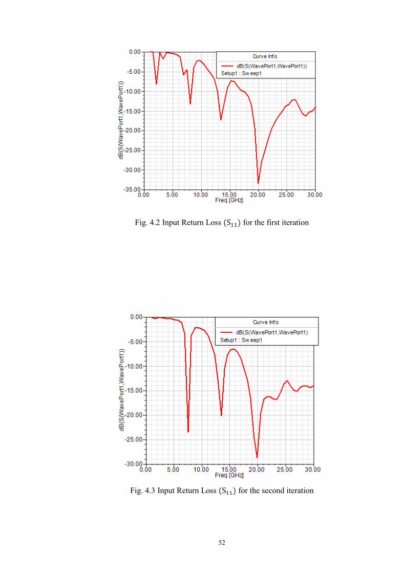
52
Fig. 4.2 Input Return Loss for the first iteration
Fig. 4.3 Input Return Loss for the second iteration
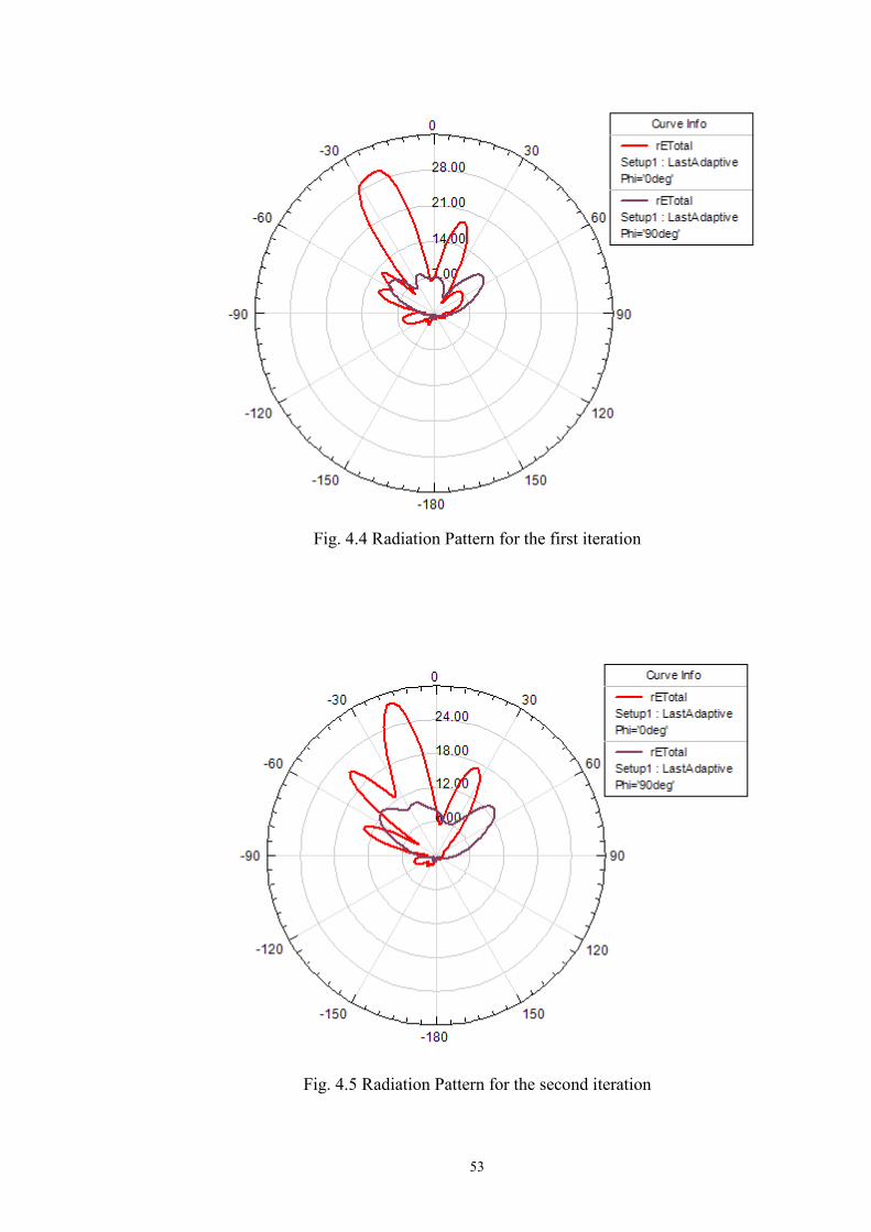
53
Fig. 4.4 Radiation Pattern for the first iteration
Fig. 4.5 Radiation Pattern for the second iteration
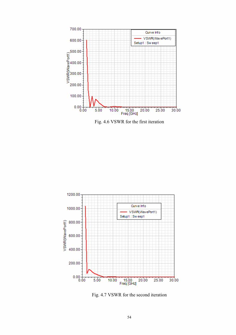
54
Fig. 4.6 VSWR for the first iteration
Fig. 4.7 VSWR for the second iteration
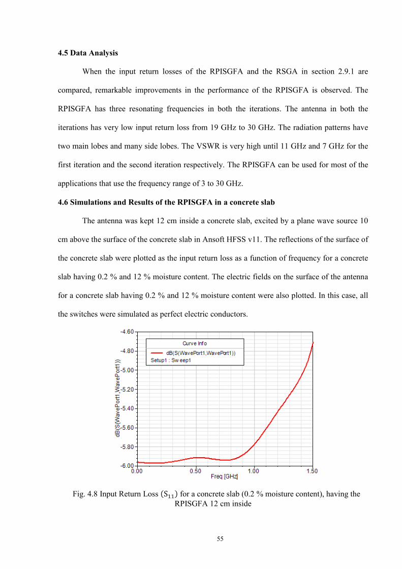
55
4.5 Data Analysis
When the input return losses of the RPISGFA and the RSGA in section 2.9.1 are
compared, remarkable improvements in the performance of the RPISGFA is observed. The
RPISGFA has three resonating frequencies in both the iterations. The antenna in both the
iterations has very low input return loss from 19 GHz to 30 GHz. The radiation patterns have
two main lobes and many side lobes. The VSWR is very high until 11 GHz and 7 GHz for the
first iteration and the second iteration respectively. The RPISGFA can be used for most of the
applications that use the frequency range of 3 to 30 GHz.
4.6 Simulations and Results of the RPISGFA in a concrete slab
The antenna was kept 12 cm inside a concrete slab, excited by a plane wave source 10
cm above the surface of the concrete slab in Ansoft HFSS v11. The reflections of the surface of
the concrete slab were plotted as the input return loss as a function of frequency for a concrete
slab having 0.2 % and 12 % moisture content. The electric fields on the surface of the antenna
for a concrete slab having 0.2 % and 12 % moisture content were also plotted. In this case, all
the switches were simulated as perfect electric conductors.
Fig. 4.8 Input Return Loss for a concrete slab (0.2 % moisture content), having the RPISGFA 12 cm inside
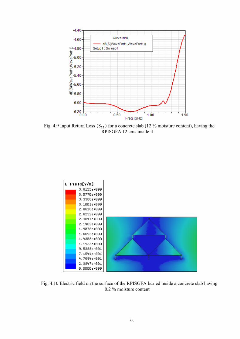
56
Fig. 4.9 Input Return Loss for a concrete slab (12 % moisture content), having the RPISGFA 12 cms inside it
Fig. 4.10 Electric field on the surface of the RPISGFA buried inside a concrete slab having 0.2 % moisture content

57
Fig. 4.11 Electric field on the surface of the RPISGFA buried inside a concrete slab having 12 % mo isture content
4.7 Additional Simulations and Results of the RPISGFA in a concrete slab
The antenna was also kept 10 cm inside a concrete slab, excited by a plane wave source
10 cm above the surface of the concrete slab in Ansoft HFSS v11. The reflections of the
surface of the concrete slab were plotted as the input return loss as a function of frequency for
a concrete slab having 0.2 % and 12 % moisture content. The electric fields on the surface of
the antenna for a concrete slab having 0.2 % and 12 % moisture content were also plotted.
Fig. 4.12 Input Return Loss for a concrete slab (0.2 % moisture content), having the
RPISGFA 10 cm inside it
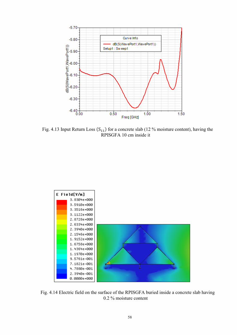
58
Fig. 4.13 Input Return Loss for a concrete slab (12 % moisture content), having the
RPISGFA 10 cm inside it
Fig. 4.14 Electric field on the surface of the RPISGFA buried inside a concrete slab having
0.2 % moisture content
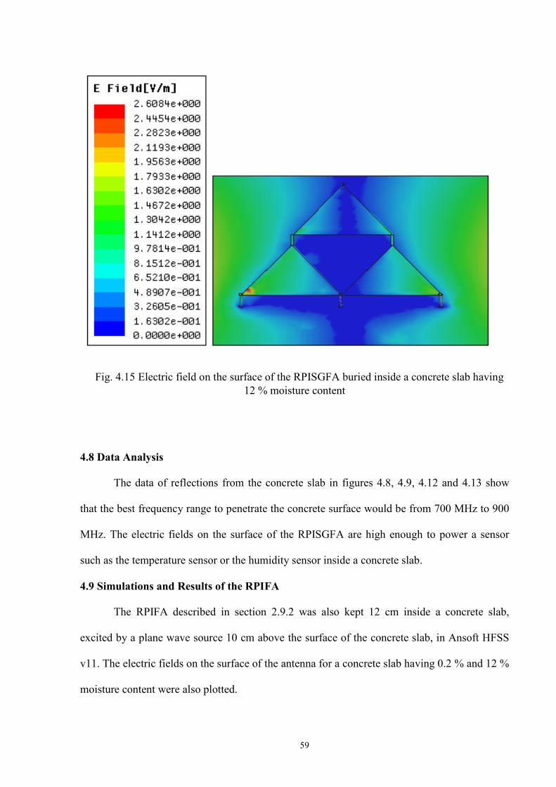
59
Fig. 4.15 Electric field on the surface of the RPISGFA buried inside a concrete slab having
12 % moisture content
4.8 Data Analysis
The data of reflections from the concrete slab in figures 4.8, 4.9, 4.12 and 4.13 show
that the best frequency range to penetrate the concrete surface would be from 700 MHz to 900
MHz. The electric fields on the surface of the RPISGFA are high enough to power a sensor
such as the temperature sensor or the humidity sensor inside a concrete slab.
4.9 Simulations and Results of the RPIFA
The RPIFA described in section 2.9.2 was also kept 12 cm inside a concrete slab,
excited by a plane wave source 10 cm above the surface of the concrete slab, in Ansoft HFSS
v11. The electric fields on the surface of the antenna for a concrete slab having 0.2 % and 12 %
moisture content were also plotted.
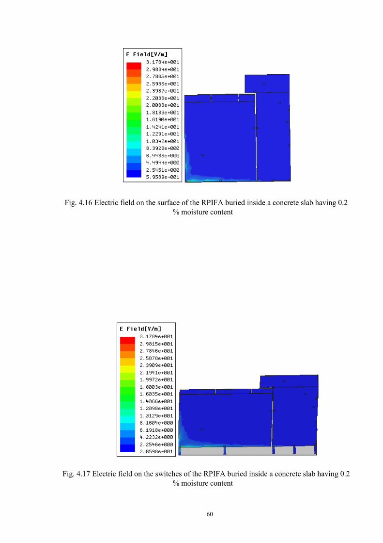
60
Fig. 4.16 Electric field on the surface of the RPIFA buried inside a concrete slab having 0.2 % moisture content
Fig. 4.17 Electric field on the switches of the RPIFA buried inside a concrete slab having 0.2
% moisture content
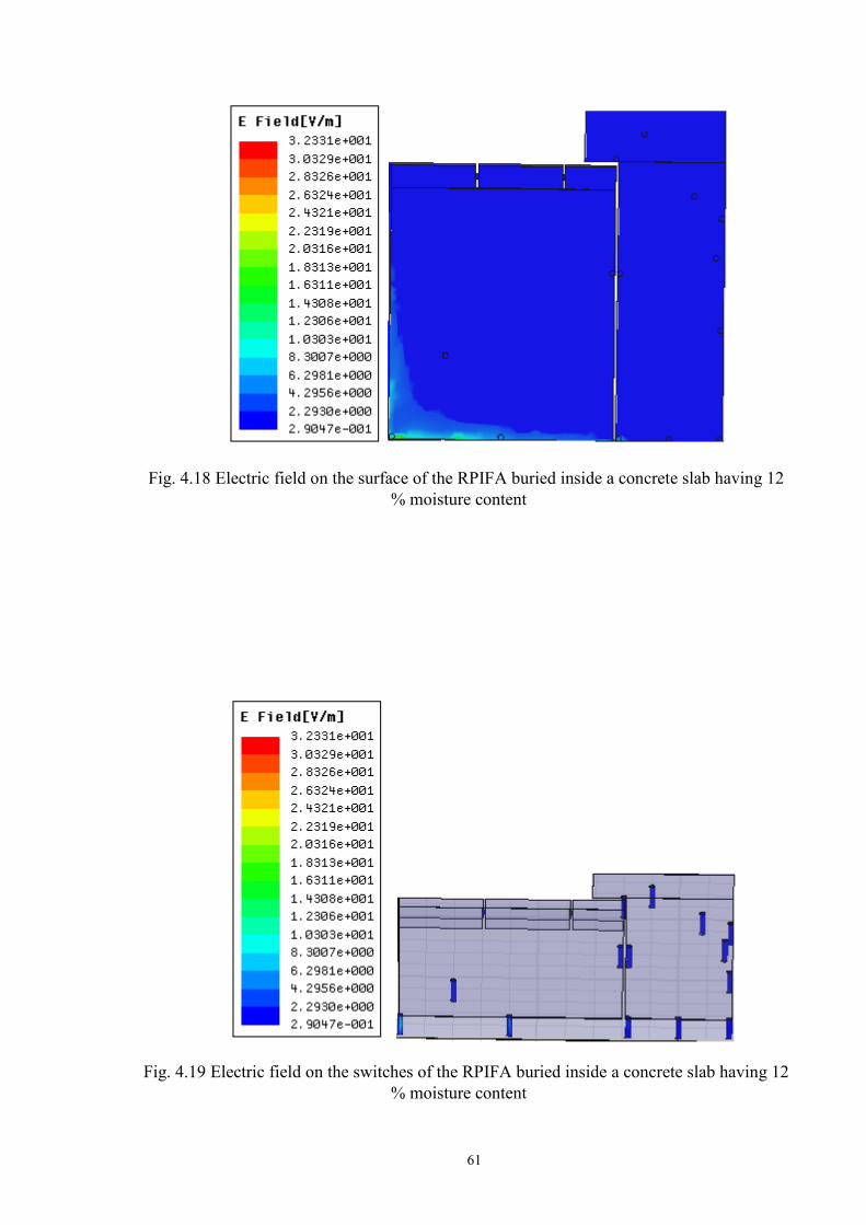
61
Fig. 4.18 Electric field on the surface of the RPIFA buried inside a concrete slab having 12 % moisture content
Fig. 4.19 Electric field on the switches of the RPIFA buried inside a concrete slab having 12 % moisture content

62
4.10 Summary
The RPISGFA has very low input return losses and can be used to enable many
applications which require an antenna with good performance. The above results of the RPIFA
and the RPISGFA in a concrete slab confirm that reconfigurable antennas are very good to
enable wireless powering. High electric fields were detected on the surface of the antennas, and
these fields can be used to power sensors wirelessly.
63
Chapter 5
Rectangular Reconfigurable Antenna (RRA) with Ultra Wideband Tuning Ability
5.1 Introduction
Reconfigurable antennas have been designed with the objective that an antenna should
have multiple resonating frequencies, and should be able to modify its radiation pattern at will.
Multiple designs of reconfigurable antennas [1] [2] have never been able to reveal the electric
field equations for the antenna. Each iteration of a reconfigurable antenna will have a different
resonating frequency and a different radiation pattern. An antenna has to be designed with the
objective that it should exhibit broadband behaviour, and has to be compact.
Reconfigurable antennas can change their radiation patterns, as well as use the same
amount of current supply to reach out to a farther distance. This research will advance the
existing designs of reconfigurable antennas, as well as design a new reconfigurable antenna to
enhance the performance of wireless devices and enable wireless powering. Instead of
increasing the input excitation current or voltage supply to the antenna, the number of radiating
surfaces can be increased to form a dynamic reconfigurable antenna which can change its size
or radiation pattern depending on what the application requires. A reconfigurable antenna can
work best at more than three frequencies, if designed optimally. Reconfigurable antennas are
cost effective to manufacture [1], very easy to fabricate, have higher bandwidth, and
favourable electrical performance. Reconfigurable antennas have multiple applications such as
Bluetooth, Satellite Digital Multimedia Broadcasting and Wireless Local Area Network
(WLAN).
A Rectangular Reconfigurable Antenna (RRA) is presented in this chapter. The antenna
system consists of 8 rectangular radiating patches. The power radiated equation, as well as the
equivalent circuit for the antenna is presented in this chapter. The electric field equations for
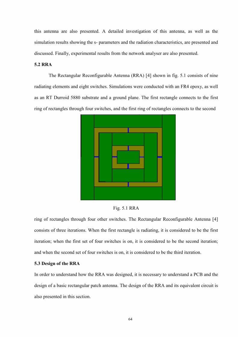
64
this antenna are also presented. A detailed investigation of this antenna, as well as the
simulation results showing the s- parameters and the radiation characteristics, are presented and
discussed. Finally, experimental results from the network analyser are also presented.
5.2 RRA
The Rectangular Reconfigurable Antenna (RRA) [4] shown in fig. 5.1 consists of nine
radiating elements and eight switches. Simulations were conducted with an FR4 epoxy, as well
as an RT Durroid 5880 substrate and a ground plane. The first rectangle connects to the first
ring of rectangles through four switches, and the first ring of rectangles connects to the second
Fig. 5.1 RRA
ring of rectangles through four other switches. The Rectangular Reconfigurable Antenna [4]
consists of three iterations. When the first rectangle is radiating, it is considered to be the first
iteration; when the first set of four switches is on, it is considered to be the second iteration;
and when the second set of four switches is on, it is considered to be the third iteration.
5.3 Design of the RRA In order to understand how the RRA was designed, it is necessary to understand a PCB and the
design of a basic rectangular patch antenna. The design of the RRA and its equivalent circuit is
also presented in this section.
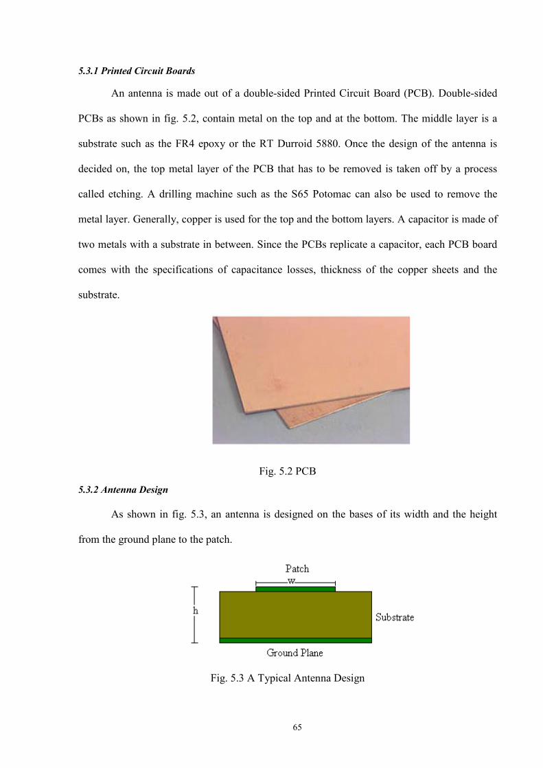
65
5.3.1 Printed Circuit Boards
An antenna is made out of a double-sided Printed Circuit Board (PCB). Double-sided
PCBs as shown in fig. 5.2, contain metal on the top and at the bottom. The middle layer is a
substrate such as the FR4 epoxy or the RT Durroid 5880. Once the design of the antenna is
decided on, the top metal layer of the PCB that has to be removed is taken off by a process
called etching. A drilling machine such as the S65 Potomac can also be used to remove the
metal layer. Generally, copper is used for the top and the bottom layers. A capacitor is made of
two metals with a substrate in between. Since the PCBs replicate a capacitor, each PCB board
comes with the specifications of capacitance losses, thickness of the copper sheets and the
substrate.
Fig. 5.2 PCB
5.3.2 Antenna Design
As shown in fig. 5.3, an antenna is designed on the bases of its width and the height
from the ground plane to the patch.
Fig. 5.3 A Typical Antenna Design
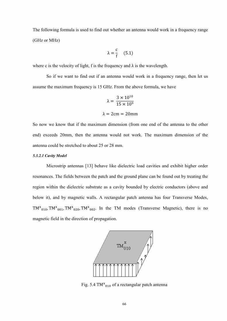
66
The following formula is used to find out whether an antenna would work in a frequency range
(GHz or MHz)
where c is the velocity of light, f is the frequency and is the wavelength.
So if we want to find out if an antenna would work in a frequency range, then let us
assume the maximum frequency is 15 GHz. From the above formula, we have
So now we know that if the maximum dimension (from one end of the antenna to the other
end) exceeds 20mm, then the antenna would not work. The maximum dimension of the
antenna could be stretched to about 25 or 28 mm.
5.3.2.1 Cavity Model
Microstrip antennas [13] behave like dielectric load cavities and exhibit higher order
resonances. The fields between the patch and the ground plane can be found out by treating the
region within the dielectric substrate as a cavity bounded by electric conductors (above and
below it), and by magnetic walls. A rectangular patch antenna has four Transverse Modes,
In the TM modes (Transverse Magnetic), there is no
magnetic field in the direction of propagation.
Fig. 5.4 of a rectangular patch antenna
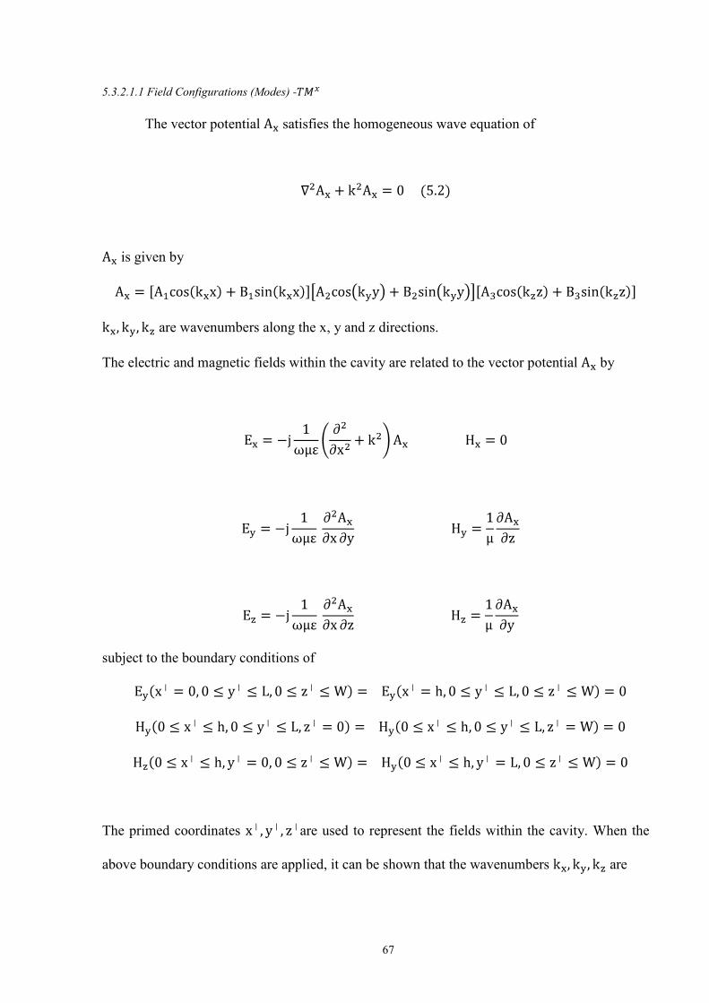
67
5.3.2.1.1 Field Configurations (Modes) -
The vector potential satisfies the homogeneous wave equation of
is given by
are wavenumbers along the x, y and z directions.
The electric and magnetic fields within the cavity are related to the vector potential by
subject to the boundary conditions of
The primed coordinates are used to represent the fields within the cavity. When the
above boundary conditions are applied, it can be shown that the wavenumbers are
68
given by
The vector potential within the cavity is
Where represents the amplitude coefficient of each mnp mode.
Hence, the wavenumbers are subject to the constraint equation
The resonant frequencies of the cavity are given by
The electric and magnetic fields within the cavity, because of a rectangular patch antenna are
given by
69
The electric and magnetic fields within the cavity of the RRA are given by
Where n denotes the number of rectangles that are radiating, and its range is given by
.
5.3.2.1.2 Fields Radiated (Radiating Slots) -
The far-zone electric fields radiated by each rectangular patch can be written as
70
Where
For very small heights, reduces to
Where
5.3.2.2 Directivity
Directivity of an antenna is given by the formula
Using the electric field equation for very small heights in section 5.3.2.1.2, the maximum
radiation intensity and radiated power for a rectangular patch antenna can be written as
Thus, the radiated power of the RRA can be written as
71
Where W denotes the width of the rectangular patch and n denotes the number of rectangles
that are radiating.
The directivity of a single patch is
Thus, the directivity of the RRA is
Where for a single slot is given by
for the RRA is given by
5.3.2.3 Transmission Line Model
A microstrip antenna behaves like a homogeneous line of one dielectric [13] (only the
substrate), and the effective dielectric constant of the antenna approaches the value of the
dielectric constant of the substrate. For low frequencies, the effective dielectric of a rectangular
patch antenna is constant. At intermediate frequencies, its values initially increase and

72
approach the dielectric constant of the substrate. The effective dielectric constant of a
rectangular patch antenna is given by
Fig. 5.5 Effective and physical lengths of a rectangular patch antenna [13]
The effective length of the patch antenna is given by
Since the length of the patch is extended by on both sides, the effective length would thus
become
A rectangular patch antenna has all its electric field lines directed into the substrate.
Thus the rectangular patch antenna does not have magnetic field in the direction of propagation
(TM transverse mode). To determine the dominant mode with the lowest resonance, the
resonant frequencies need to be examined. For all microstrip antennas h L and h W. For the
dominant mode where L W h (as shown in fig. 5.4), the resonating frequency (Hz) of
the rectangular patch antenna is a function of the length given by

73
Where is the free space velocity of light.
For an efficient radiator, a practical width [66] that leads to a good radiation pattern is
where is the free-space velocity of light and is the resonating frequency.
The length of the patch L can be determined by
Since the length and the width of a rectangular patch antenna are inversely proportional to the
resonating frequency, if the length and the width are varied, then the resonating frequency
would also change. This idea of varying the length and the width to obtain multiple resonating
frequencies was used to create the RRA. The centre rectangular patch of the RRA can be
designed for a frequency, and an incremental length can be used to create rings of rectangles.
The RRA has five rectangles which have different lengths and widths, thus giving it five
different resonating frequencies.
5.3.2.3.1 Conductance
Each radiating rectangular patch is represented by a parallel equivalent admittance Y
(with conductance G and susceptance B), as shown in fig. 5.6.
Fig. 5.6 Rectangular Patch with its equivalent circuit transmission model
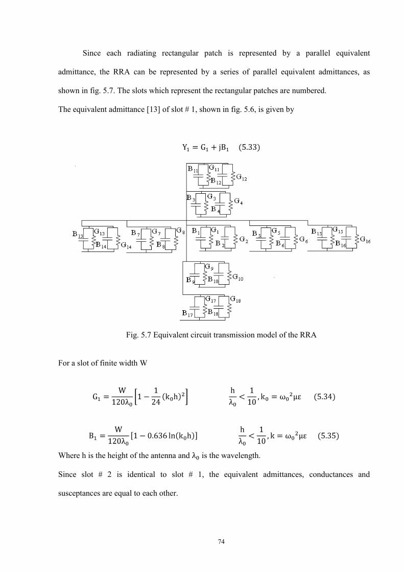
74
Since each radiating rectangular patch is represented by a parallel equivalent
admittance, the RRA can be represented by a series of parallel equivalent admittances, as
shown in fig. 5.7. The slots which represent the rectangular patches are numbered.
The equivalent admittance [13] of slot # 1, shown in fig. 5.6, is given by
Fig. 5.7 Equivalent circuit transmission model of the RRA
For a slot of finite width W
Where h is the height of the antenna and is the wavelength.
Since slot # 2 is identical to slot # 1, the equivalent admittances, conductances and
susceptances are equal to each other.

75
Thus,
The conductance of the first slot is given by
Using the power radiated equation for a single rectangular patch, the conductance can be
written as
Asymptotic values of the above two equations are
In order to derive the conductance and the susceptance of the RRA, the equivalent
circuit and the design of the RRA have to be closely examined. The rings of rectangular
radiators are attached to each other, as shown in fig. 5.1. The outer and inner rings of
rectangular radiators are connected to each other through four switches, and the inner ring of
radiators is connected to the central rectangular patch through four other switches.
Fig. 5.8 Analysis of the Equivalent circuit transmission model of the RRA
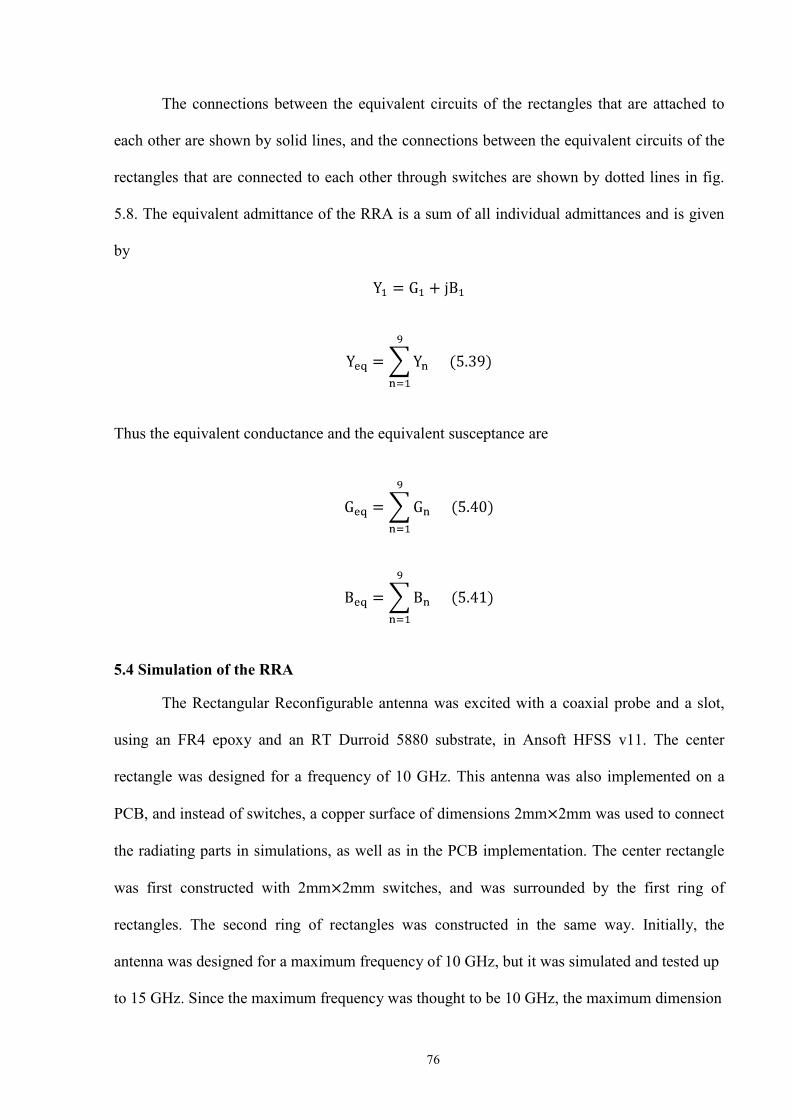
76
The connections between the equivalent circuits of the rectangles that are attached to
each other are shown by solid lines, and the connections between the equivalent circuits of the
rectangles that are connected to each other through switches are shown by dotted lines in fig.
5.8. The equivalent admittance of the RRA is a sum of all individual admittances and is given
by
Thus the equivalent conductance and the equivalent susceptance are
5.4 Simulation of the RRA
The Rectangular Reconfigurable antenna was excited with a coaxial probe and a slot,
using an FR4 epoxy and an RT Durroid 5880 substrate, in Ansoft HFSS v11. The center
rectangle was designed for a frequency of 10 GHz. This antenna was also implemented on a
PCB, and instead of switches, a copper surface of dimensions 2mm 2mm was used to connect
the radiating parts in simulations, as well as in the PCB implementation. The center rectangle
was first constructed with 2mm 2mm switches, and was surrounded by the first ring of
rectangles. The second ring of rectangles was constructed in the same way. Initially, the
antenna was designed for a maximum frequency of 10 GHz, but it was simulated and tested up
to 15 GHz. Since the maximum frequency was thought to be 10 GHz, the maximum dimension

77
can be calculated as
Where c is the velocity of light and f is the maximum frequency. Substituting the values of c
and f we get
Finally we get
The maximum length of the substrate could not be more than 30 mm, but in this case a
substrate of length 33.06 mm and breadth 35.86 mm was used to simulate the antenna up to 15
GHz when it was excited using the coaxial probe feed. This decision to simulate and test the
antenna up to 15 GHz was taken, as there could be coupling between the radiating parts that
could alter the results. These coupling effects could be reduced by introducing filters at the end
points of the switches. The width of the centre rectangle is w1=9.06 mm and the length is
l1=11.86 mm. The rectangles opposite to each other have the same dimensions in the first and
the second rings of rectangles. The second ring of rectangles consists of four rectangles with
dimensions: l2=13.06 mm and w2=5mm; l3=5mm and w3=25.9mm. The dimensions of the
third ring of rectangles are: l4=27.06mm and w4=3mm; l5=3mm and w5=35.89mm. The
thickness of the radiating part and the ground plane is 0.017mm. This antenna would have five
resonating frequencies in the third iteration, as this antenna has five dimensions of rectangles,
and each particular dimension would produce one resonating frequency.
5.4.1 Simulation of the RRA with a coaxial probe feed
The radius of the inner cylinder of the coaxial probe was 1 mm, and the height was
taken to be 4 mm. The input return losses, VSWR and the radiation pattern, were compared
when the antenna was simulated using an FR4 epoxy and an RT Durroid 5880 substrate.
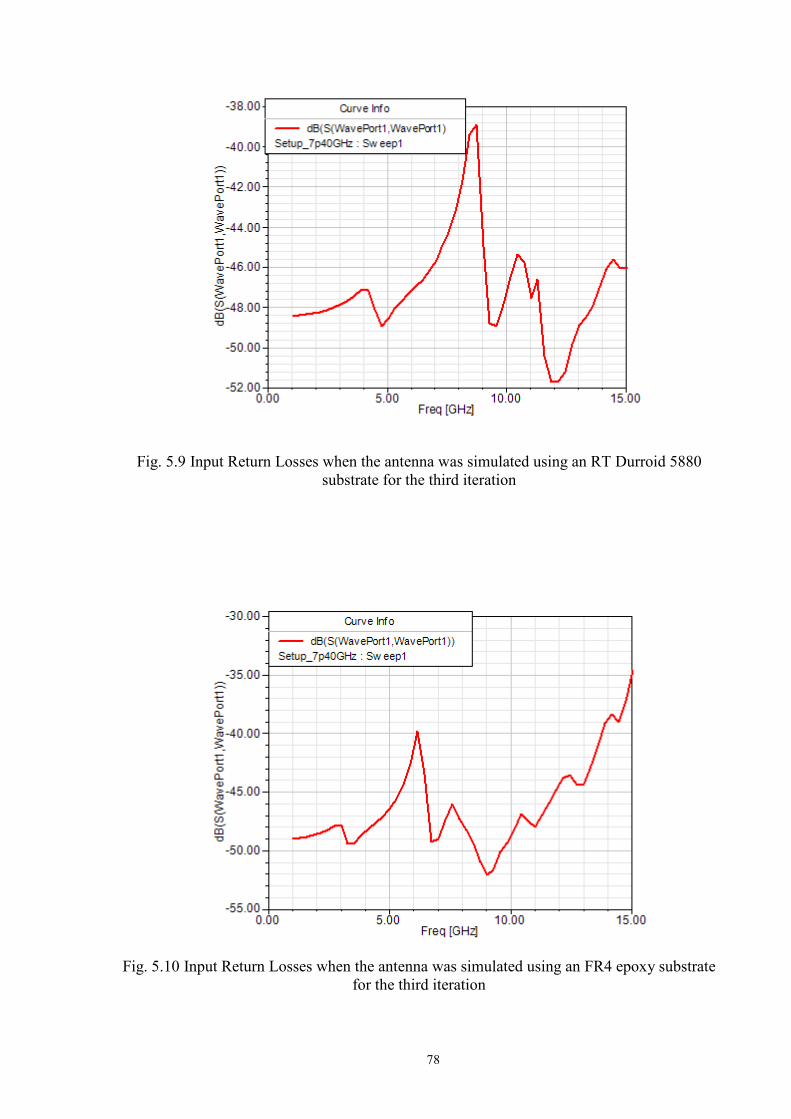
78
Fig. 5.9 Input Return Losses when the antenna was simulated using an RT Durroid 5880
substrate for the third iteration
Fig. 5.10 Input Return Losses when the antenna was simulated using an FR4 epoxy substrate
for the third iteration
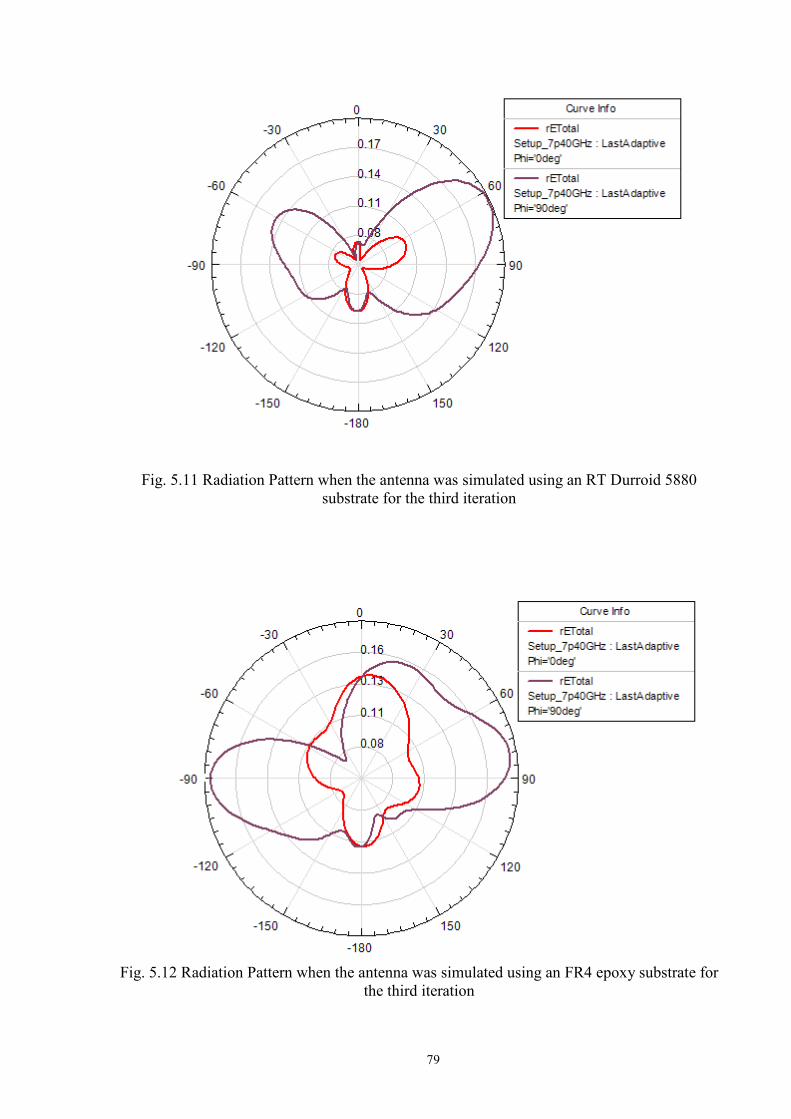
79
Fig. 5.11 Radiation Pattern when the antenna was simulated using an RT Durroid 5880 substrate for the third iteration
Fig. 5.12 Radiation Pattern when the antenna was simulated using an FR4 epoxy substrate for the third iteration

80
Fig. 5.13 VSWR when the antenna was simulated using an RT Durroid 5880 substrate for the third iteration
Fig. 5.14 VSWR when the antenna was simulated using an FR4 epoxy substrate for the third iteration
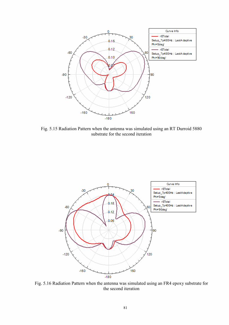
81
Fig. 5.15 Radiation Pattern when the antenna was simulated using an RT Durroid 5880
substrate for the second iteration
Fig. 5.16 Radiation Pattern when the antenna was simulated using an FR4 epoxy substrate for the second iteration
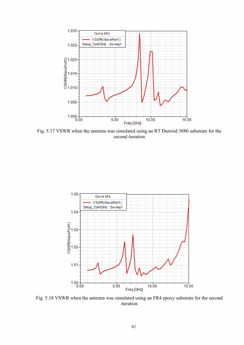
82
Fig. 5.17 VSWR when the antenna was simulated using an RT Durroid 5880 substrate for the second iteration
Fig. 5.18 VSWR when the antenna was simulated using an FR4 epoxy substrate for the second iteration
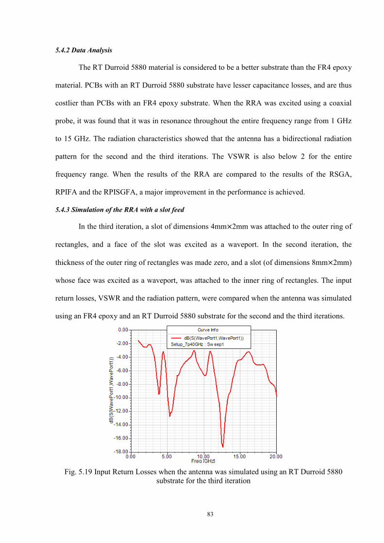
83
5.4.2 Data Analysis
The RT Durroid 5880 material is considered to be a better substrate than the FR4 epoxy
material. PCBs with an RT Durroid 5880 substrate have lesser capacitance losses, and are thus
costlier than PCBs with an FR4 epoxy substrate. When the RRA was excited using a coaxial
probe, it was found that it was in resonance throughout the entire frequency range from 1 GHz
to 15 GHz. The radiation characteristics showed that the antenna has a bidirectional radiation
pattern for the second and the third iterations. The VSWR is also below 2 for the entire
frequency range. When the results of the RRA are compared to the results of the RSGA,
RPIFA and the RPISGFA, a major improvement in the performance is achieved.
5.4.3 Simulation of the RRA with a slot feed
In the third iteration, a slot of dimensions 4mm 2mm was attached to the outer ring of
rectangles, and a face of the slot was excited as a waveport. In the second iteration, the
thickness of the outer ring of rectangles was made zero, and a slot (of dimensions 8mm 2mm)
whose face was excited as a waveport, was attached to the inner ring of rectangles. The input
return losses, VSWR and the radiation pattern, were compared when the antenna was simulated
using an FR4 epoxy and an RT Durroid 5880 substrate for the second and the third iterations.
Fig. 5.19 Input Return Losses when the antenna was simulated using an RT Durroid 5880 substrate for the third iteration

84
Fig. 5.20 Input Return Losses when the antenna was simulated using an FR4 epoxy substrate for the third iteration
Fig. 5.21 Radiation Pattern when the antenna was simulated using an RT Durroid 5880 substrate for the third iteration
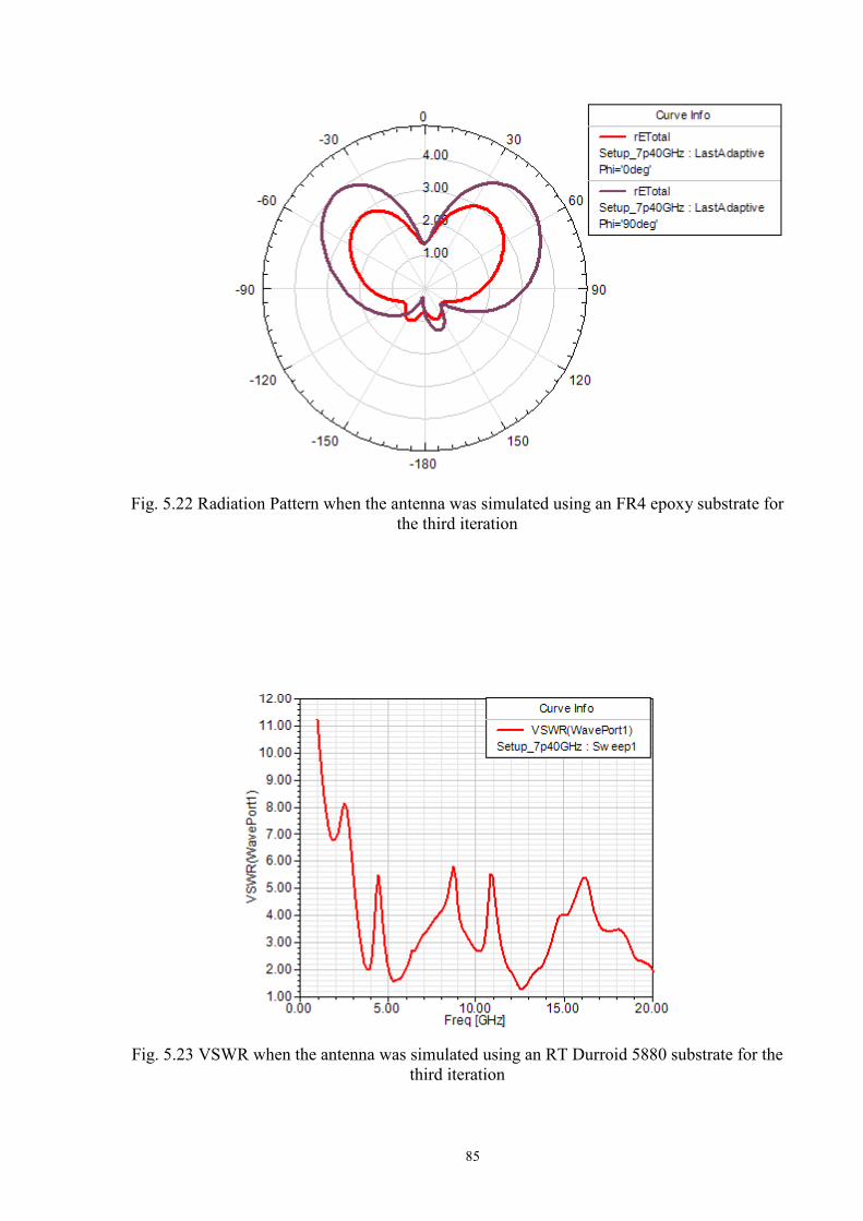
85
Fig. 5.22 Radiation Pattern when the antenna was simulated using an FR4 epoxy substrate for
the third iteration
Fig. 5.23 VSWR when the antenna was simulated using an RT Durroid 5880 substrate for the third iteration

86
Fig. 5.24 VSWR when the antenna was simulated using an FR4 epoxy substrate for the third iteration
Fig. 5.25 Radiation Pattern when the antenna was simulated using an RT Durroid 5880 substrate for the second iteration
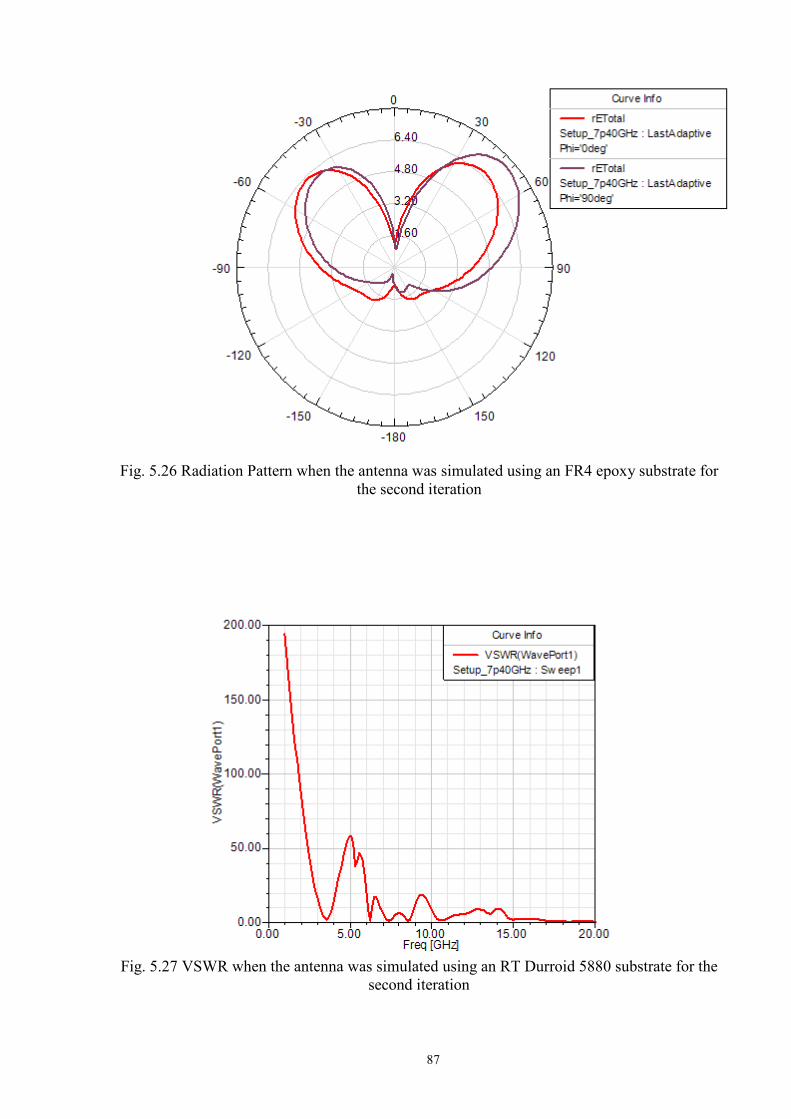
87
Fig. 5.26 Radiation Pattern when the antenna was simulated using an FR4 epoxy substrate for the second iteration
Fig. 5.27 VSWR when the antenna was simulated using an RT Durroid 5880 substrate for the second iteration
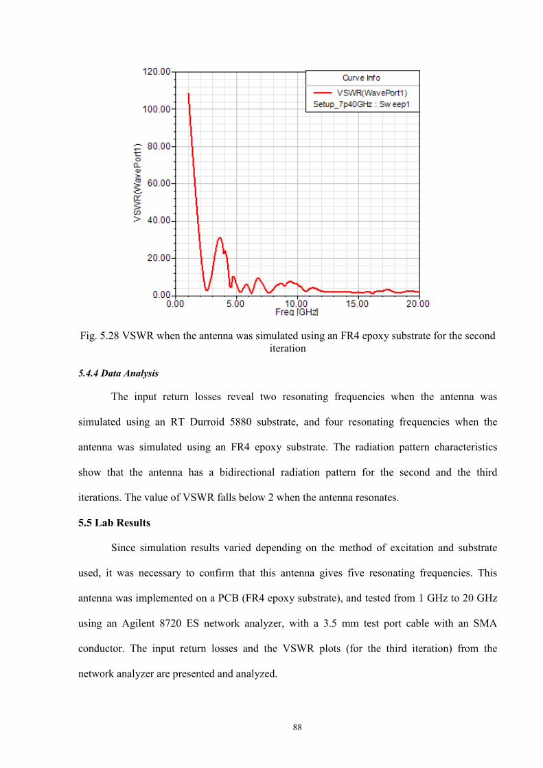
88
Fig. 5.28 VSWR when the antenna was simulated using an FR4 epoxy substrate for the second
iteration
5.4.4 Data Analysis
The input return losses reveal two resonating frequencies when the antenna was
simulated using an RT Durroid 5880 substrate, and four resonating frequencies when the
antenna was simulated using an FR4 epoxy substrate. The radiation pattern characteristics
show that the antenna has a bidirectional radiation pattern for the second and the third
iterations. The value of VSWR falls below 2 when the antenna resonates.
5.5 Lab Results
Since simulation results varied depending on the method of excitation and substrate
used, it was necessary to confirm that this antenna gives five resonating frequencies. This
antenna was implemented on a PCB (FR4 epoxy substrate), and tested from 1 GHz to 20 GHz
using an Agilent 8720 ES network analyzer, with a 3.5 mm test port cable with an SMA
conductor. The input return losses and the VSWR plots (for the third iteration) from the
network analyzer are presented and analyzed.
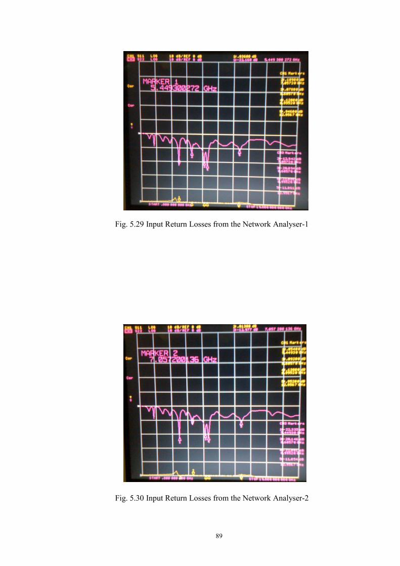
89
Fig. 5.29 Input Return Losses from the Network Analyser-1
Fig. 5.30 Input Return Losses from the Network Analyser-2
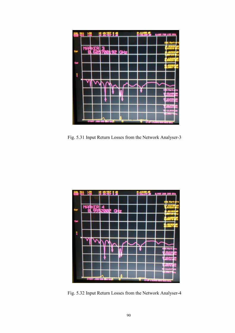
90
Fig. 5.31 Input Return Losses from the Network Analyser-3
Fig. 5.32 Input Return Losses from the Network Analyser-4
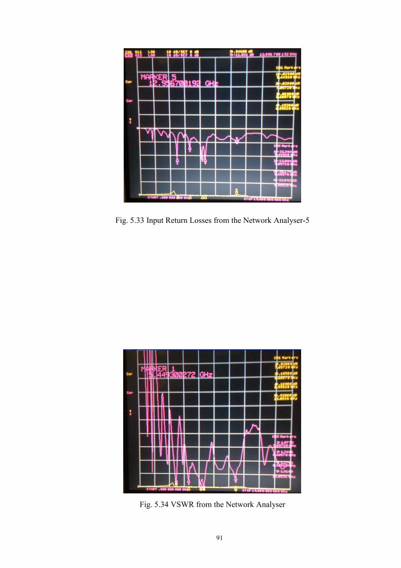
91
Fig. 5.33 Input Return Losses from the Network Analyser-5
Fig. 5.34 VSWR from the Network Analyser

92
5.6 Summary
The Rectangular Reconfigurable antenna can be analysed mathematically, and has
multiple resonating frequencies. The design of the Rectangular Reconfigurable antenna is very
simple, and more rectangular rings can be added to create more iterations. This antenna can be
designed for the MHz and GHz frequency ranges. The antenna was found to be an
ultrawideband antenna from our simulations, when it was excited using a coaxial probe feed.
Analysing the results from the network analyser, it was found that this antenna definitely has 5
resonating frequencies, 3 of which are below -20 dB, and 2 of which are below -10 dB. This
antenna can facilitate wireless powering, as it can be designed for any frequency range; and the
eight switches can be used as eight separate feeder points to take power that is incident on the
antenna. This antenna is small enough to be used in wireless applications, and the performance
of these wireless applications can be enhanced by using this antenna. The fact that 5 resonating
frequencies have been obtained is a significant contribution to the field of antenna research.

93
Chapter 6
Conclusions and Future Work
This dissertation explores the idea of enabling wireless powering in a concrete slab
through enhanced reconfigurable antennas designs. The following are the major contributions
made by this dissertation:
1. Simulations of a concrete slab in chapters 2 and 3 show that wireless powering in a
concrete slab is possible, and can be done efficiently. The penetration of the surface of a
concrete slab by a plane wave has not been done previously. Investigation of the
penetration of the surface of a concrete slab, and the electric fields on the surface of the
reconfigurable antennas inside the concrete slab, have shown that sensors can be powered
wirelessly inside a concrete medium.
2. A novel planar inverted fractal antenna design has been shown in chapter 3. The results
from the RPISGFA have shown that the antenna has four resonating frequencies, which is a
huge improvement when compared to the RSGA and the RPIFA.
3. Since the RPISGFA was made of two copper sheets above and below each other, a simpler
antenna design with better performance was needed. The RRA has a simple design, and is a
traditional microstrip antenna. Previous reconfigurable antenna designs have not been able
to reveal the electric field, as well as the power radiated and directivity equations.
Extensive mathematical analysis of the RRA is presented in this dissertation. Simulation
results of the RRA with different substrates when it was excited using the coaxial probe
and the slot are also presented.
4. The RRA was built on a double-sided PCB and tested using a network analyser to show
that the lab results are matching the mathematical analysis. The results from the network
analyser show much better performance than the RPISGFA, the RSGA and the RPIFA.

94
5. Even if the RRA is not made reconfigurable with switches, the 2mm 2mm incremental
lengths can still be used to convert the reconfigurable antenna into an ordinary antenna.
6.1 Future Work
The major focus of this dissertation involves four research areas:
1. Studying the existing reconfigurable antenna designs and identifying their short comings
2. Investigating the performance of reconfigurable antennas inside the concrete slabs
3. Creating a new reconfigurable planar inverted fractal antenna design
4. Creating a new reconfigurable microstrip antenna design and testing it using a network
analyser
The investigation of reconfigurable antennas inside a concrete slab has been limited to
simulation results. The new reconfigurable antennas presented in this dissertation, such as the
RRA, and the RPISGFA, have to be fabricated and placed inside a concrete slab, and lab
results have to be obtained. If an antenna is radiating more than 400 mW of power when it is
close to the human brain, then it could cause brain cancer. Therefore, such experiments of
reconfigurable antennas inside a concrete slab should be carried out in an anechoic chamber for
safety purposes.
The RPISGFA and the RRA have to be fabricated and tested in an anechoic chamber.
So far, only the input return losses and the radiation patterns of reconfigurable antennas have
been tested in anechoic chambers. The RPISGFA and the RRA should be made to transmit a
signal to another antenna, and their performance should be compared to an ordinary antenna.
Reconfigurable antennas consist of multiple antennas that are turned on or off using switches.
The coupling effects between the multiple radiating patches needs to be studied. Filters can be
used to reduce these coupling effects. Effective filters need to be designed for the RPISGFA
and the RRA if coupling exists between the radiating patches.Instead of switches, the
RPISGFA and the RRA have to be simulated with diodes. If a positive external voltage is

95
applied to diodes, then, at a certain voltage the diode is turned on. Similarly, at a certain
negative potential the diode is turned off. These effects are popularly known as the forward
bias and the reverse bias effects. These effects of a diode to external voltage allow them to be
used as switches for reconfigurable antennas. The performance of the RPISGFA and RRA has
to be tested using diodes in an anechoic chamber.
Micro Electro Mechanical Systems (MEMS) switches are also used in reconfigurable
antennas. MEMS switches are fabricated using materials such as sapphire, quartz and barium
chloride. Some MEMS switches also consist of cantilever beams. A voltage potential called the
actuation voltage is used to turn the MEMS switch on. The actuation voltage depends on the
design of MEMS switches, and it ranges from 2V to 90V. MEMS switches provide ultra-low
losses, high isolation, and high linearity of relays. MEMS switches are usually used in military
applications. The novel reconfigurable antennas shown in this dissertation, such as the
RPISGFA and the RRA, have to be fabricated with MEMS switches. The MEMS switch
fabricated RPISGFA and the RRA should be made to transmit a signal to another receiving
antenna, and their performance should be compared to an ordinary antenna.
Multiple-Input and Multiple-Output (MIMO) systems consist of multiple antennas at
both the transmitter and receiver to improve communication performance. So far, MIMO
systems have only been developed with array antennas. MIMO systems need to be developed
with reconfigurable antennas. The coupling effects of reconfigurable antennas in a MIMO
environment need to be studied.

96
BIBLIOGRAPHY
[1] Loizeau, S, Sibille, “A.Reconfigurable PIFA Antenna with Ultrawideband Tuning”, Antennas and propagation, 2007, EuCAP 11-16 Nov. 2007, pp 1-6, ISBN: 978-0-86341-842-6.
[2] N. Kingsley, D. E. Anagnostou, M. Tentzeris, and J. Papapolymerou, "Novel Design for MEMS Reconfigurable Sierpinski Antenna on a Flexible, Organic Substrate Without DC Bias Lines", IEEE/ASME Journal of MEMS.
[3] Punjala Shishir,“Wireless Powering of Sensors inside Concrete”,International Conference on Advanced Technologies for Communication,Hanoi 2008.
[4] Punjala Shishir, Kia Makki “Rectangular Reconfigurable Antenna (RRA) with Ultra Wideband Tuning Ability”, EUCAP 2009 .
[5] Punjala Shishir,Kia Makki,“Wireless Powering of Sensors inside Concrete using a Reconfigurable Sierpinski Gasket Antenna”, EUCAP 2009.
[6] Punjala Shishir,Kia Makki, “Wireless Powering of Sensors inside Concrete using a Reconfigurable PIFA antenna”, ANTEM/URSI 2009.
[7] L Sandrolini, U Reggiani and A Ogunsola,“Modeling the electrical properties of concrete for shielding effectiveness prediction”, Journal of Physics and Applied Sciences, 2007.
[8] Shantanu A. Bhalerao, Abhishek V. Chaudhary, Raghavendra B. Deshmukh, Rajendra M. Patrikar, “Powering Wireless Sensor Nodes using Ambient RF Energy”, 2006 IEEE International Conference on Systems, Man, and Cybernetics October 8-11, 2006, Taipei, Taiwan.
[9] Miaoudakis, A. Zacharopoulos, V. Stratakis, D. Antonidakis, E., “Self-powering wireless sensors in typical building environment”, Globecom Workshops, 2007 IEEE, 26-30 Nov. 2007, page(s): 1-8, ISBN: 978-1-4244-2024-7.
[10] Soutsos M, Bungey J, Millard S, Shaw M and Patterson A,2001 NDT&E Int.34419-25 ISSN 0963-8695.
[11] Shaari A, Millard S G and Bungey J H 2004 NDT&E Int. 37237-242.
[12] Constantine A. Balanis, “Advanced Engineering Electromagnetics”, second edition, Wiley Publications, 1997.
97
[13] Constantine A. Balanis, “Antenna Theory, Analysis and Design”, Wiley Publications, Third Edition, 1997.
[14] Fawwaz T. Ulaby, “Electromagnetics for Engineers”, Pearson Education, 2005. [15] Abdias Magalhäes Gomes, Juliana Oliveira Costa, Horácio Albertini, José Eduardo
Aguiar, “Permeability of Concrete: A Study Intended for the "in situ" Valuation Using Portable Instruments and Traditional Techniques”, Non-Destructive Testing in Civil Engineering, International Symposium (NDT-CE 2003).
[16] Kazimierz Siwiak and Yasaman Bahreini, ”Radiowave Propagation and Antennas for Personal Communication, Third Edition, Artech House, 2007.
[17] Dennis Roddy, “Satellite Communications”, Fourth Edition, McGraw-Hill, 2007.
[18] Juan M. Rius, Jose Maria Gonzalez Arbesú, Jordi, Romeu, Eugenia Cabot, Michael Mattes, Juan R. Mosig, Rafael Gómez, Amelia Rubio, Mario Fernadez Pantoja, “Exploring the limits of Fractal Electrodynamics for the future Telecommunication Technologies”, July 31 2003, IST-2001-33055
[19] Cetiner, B.A. Jofre, L. Chang, C.H. Qian, J.Y. Bachman, M. Li, G.P. De Flaviis, F. “Integrated MEM antenna system for wireless communications ”, Dept. of Electr. & Comput. Eng., California Univ., Irvine, CA, Microwave Symposium Digest, 2002 IEEE MTT-S International.
[20] Cetiner, B.A. Jafarkhani.H, Jiang-Yuan Qian, Hui Jae Yoo Grau, A. De Flaviis, F. “Multifunctional reconfigurable MEMS integrated antennas for adaptive MIMO systems”, Center of Space Sci., Morehead State Univ., NC, USA, Communications Magazine, IEEE, 2004.
[21] Feldner,L.M.Nordquist, C.D. Christodoulou, C.G. “RF MEMS reconfigurable triangular patch antenna”, Antennas and Propagation Society International Symposium, 2005 IEEE.
[22] B. N. Kim, S. O. Park, Y. S. Yoon, J. K. Oh, K. J. Lee, and G. Y. Koo, “Hexaband Planar Inverted-F Antenna With Novel Feed Structure for Wireless Terminals”, IEEE Antennas and Wireless Propagation Letters, Vol. 6, pp. 66-69, 2007
[23] H. P.Chang et al.,“Low Cost RF MEMS Switches Fabricated on Microwave Laminate PCBs,” IEEE Elect. Device Lett., vol. 24, no.4, Apr. 2003, pp. 227–29.
[24] W. Arrighetti, P. De Cupis, G. Gerosa, “Circuit Models for the Sierpinski Gasket Antenna”, physics/0510069, Computational Physics , Electronic Engineering Department, "La Sapienza" University of Rome, Italy, WMB0022-E .
98
[25] C.C Liu, A.Hessel and J.Shmoys, “Performance of Probe-Fed Rectangular Microstrip Patch Element Phased Arrays”, IEEE Trans. Antennas Propagat., Vol. AP-36, No. 11, pp. 1501-1509, November 1988.
[26] Sava V. Savov and Matti H. A. J. Herben, “Modal Transmission-Line Modeling of Propagation of Plane Radio waves through Multilayer Periodic Building Structures”, IEEE Transactions on Antennas and Propagation, Vol. 51, No. 9, September 2003.
[27] WilliamLee,“Mobile Cellular Telecommunications Analog and Digital Systems”,Second Edition,McGraw-Hill International Editions, 1995.
[28] M.Kulkarni, “Microwave and Radar Engineering”, Third Edition, Umesh Publications, 2003.
[29] S. Meninger, J.O. Mur-Miranda, R. Amirtharajah, A. Chandrakasan, J.H. Lang, "Vibration-to-electric energy conversion", IEEE Trans. VLSI Systems, " pp. 64-76, Vol. 9, Issue 1, Feb 2001.
[30] Seshagiri Krishnamoorthy, "Interference measurements and throughput analysis for 2.4 GHz wireless devices in hospital environments", MS Thesis, Dept. Elect. Eng., Virginia polytechnic and State Univ., Blacksburg, Virginia, 2003.
[31] Adam M. Alevy, "In-Building propagation measurements at 2.4 Ghz", in Wireless Symposium Feb. 2002.
[32] I.F. Akyildiz, Weilian Su, Y. Sankarasubramaniam, E. Cayirci, "A Survey on Sensor Networks", in IEEE Communications Magazine, pp.102-114, Vol. 40, Issue 8, Aug, 2002.
[33] J.A. Hagerty, et al, "Recycling ambient microwave energy with broad-band rectenna arrays", IEEE Trans. Microwave theory and techniques, pp.1014-1024, vol. 52, issue 3,
Mar. 2004.
[34] F. Kocer, P.M. Walsh, M.P. Flynn, "An RF powered, wireless temperature sensor in quarter micron CMOS", in Proc. ofISCAS'04, pp. IV-876-879, Vol. 4, May 2004
[35] R.L. Li, G. DeJean, E. Tsai, E. Tentzeris, J. Laskar, "Novel; small folded shorted patch antennas", in IEEE Int. Symp. Antennas and Propagation Society, pp. 26-29, vol. 4, 16-21 Jun 2002.
[36] D. E. Anagnostou et al., “Design, fabrication, and measurements of an RF-MEMS-based self-similar reconfigurable antenna,” IEEE Trans. Antennas Propag., vol. 54, no. 2, pt. 1, pp. 422–432, Feb. 2006.

99
[37] D.Werner and S.Ganguly,“An overview of fractal antenna engineering research,”IEEE AntennasPropag. Mag., vol. 45, no. 1, pp. 38–57, Feb. 2003.
[38] J. Anguera, C. Puente, C. Borja, and J. Soler, “Fractal-shaped antennas: A review,” in Wiley Encyclopedia of RF and Microwave Engineering, vol. 2, K. Chang, Ed. New York: Wiley, 2005, pp. 1620–1635.
[39] C. Puente, J. Romeu, R. Pous, X. Garcia, and F. Benitez, “Fractal multiband antenna based on the Sierpinski gasket,” Electron. Lett., vol. 32, no. 1, pp. 1–2, Jan. 1996.
[40] D. E. Anagnostou, G. Zheng, L. Feldner,M. T. Chryssomallis, J. C. Lyke,J. Papapolymerou, and C. G. Christodoulou, “Silicon-etched re-configurable self-similar antenna with RF-MEMS switches,” in Proc. Antennas and Propagation Society Symp., vol. 2, Jun. 20–25, 2004, pp. 1804–1807.
[41] D.Culler, D. Estrin, M. Srivastava, “Overview of Sensor Networks”, IEEE Computer Magazine, pp. 41-49, August 2004.
[42] Martinez, K.;Hart,J.K.;Ong, R.,“Environmental Sensor Networks”,IEEE Computer Magazine, Vol. 37, Issue 8, Page(s):50 – 56, Aug. 2004.
[43] Andreas Willing , Kirsten Matheus and Adam Woliszd, “Wireless Technology in Industrial Networks,”Proceedings of IEEE, vol. 93, no. 6, pp. 1130-1151, June 2005.
[44] Humirel HM1500LF humidity sensor datasheet available online at http://humirel.com/
[45] IEEE Standard Definitions of Terms of Antennas,IEEEStd 145-1993,SH16279,March 28,1993.
[46] IEEE Standard Definitions of Terms for Radio Wave Propagation, IEEE Std 211- 1990, SH13904,1990.
[47] I. Lier and K. R. Jakobsen, “Rectangular Microstrip Patch Antenna with Infinite and Finite Ground-Plane Dimensions”, IEEE Trans. Antennas Propagat., Vol. AP-31, No. 6, pp. 978-984, Nov 1983.
[48] R. W. Lee, K. F. Lee and J. Bonbinchak, “Characteristics of a Two-Layer Electromagnetically Coupled Rectangular Patch Antenna,” Electronic Letters, Vol.23, pp. 1070-1072, September 1987.
[49] G. Gronau and I. Wolff, “Aperture-Coupling of a Rectangular Microstrip Resonator”, Electronic Letters, Vol. 22, pp. 554-556, May 1986.
100
[50] J. R. Mosig and F. E. Gardiol, “General Integral Equation Formulation for Microstrip Antennas and Scatterers,” Proc. Inst. Elect. Eng., pt. H, Vol. 132, pp. 424-432, 1985.
[51] C.C.Liu, A. Hessel and J. Shmoys, “Performance of Probe-Fed Rectangular Microstrip Patch Element Phased Arrays,” IEEE Trans. Antennas Propagat., Vol. AP-36, No. 11, pp. 1501-1509, Nov 1988.
[52] Philip Felber “Fractal Antennas” A Literature Study, Illinois Institute of Technology, Dec 2000.
[53] K.D Prasad “Antenna & Wave Propagation” Third Edition, 1995.
[54] F.R. Terman,” Electronic Radio and Engineering”. MacGraw-Hill.
[55] P.Lorrain, D. R. Corson, and F. Lorrain. “Electromagnetic fields and waves: including electric circuits”. Freeman, New York, 1988.
[56] Pozar, David M. “Microwave Engineering”, Third Edition (Intl. Ed.); John Wiley & Sons, 2005, Inc.; pp 170-174. ISBN 0-471-44878-8.
[57] J Choma & WK Chen. “Feedback networks: theory and circuit applications”. Singapore: World Scientific. Chapter 3, p. 225 ff, 2007. ISBN 981-02-2770-1.
[58] Hutchinson,Chuck,“The ARRL Handbook for Radio Amateurs 2001”Newington,CT: ARRL—the national association for Amateur Radio.pp. g. 20.2. ISBN 0-87259-186-7.
[60] Elkamchouchi. H, Nasr. M.A, “3D-Fractal Rectangular Koch Dipole and Hilbert Dipole Antennas”, Microwave and Millimeter Wave Technology, 2007. ICMMT '07, 18-21 April 2007, Page(s):1-4, Digital Object Identifier 10.1109/ICMMT.2007.381294.
[61] Douglas H. Werner and Raj Mittra,"Frontiers in Electromagnetics," New York,IEEE Press, 2000.
[62] John Gianvittorio,“Fractals, MEMS, and FSS Electromagnetic Device: Miniaturization and Multiple Resonances,” PhD dissertation, University of California, Los Angeles, 2003.
[63] J. M. Gonzalez, S. Blanch, J. Romeu, "The Hilbert Curve as a Small Self- Resonant Monopole From a Practical Point of View", Microwave Optical Technology Letters., vol. 39, no. 1, October 2001.
[64] Iulian Rosu, “PIFA – Planar Inverted F Antenna”, YO3DAC / VA3IUL, RF Technical Articles.

101
[65] Leland et al. "On the self-similar nature of Ethernet traffic", IEEE/ACM Transactions on Networking, Volume 2, Issue 1, February 1994.
[66] I.J. Bahl amd P. Bhartia, “Microstrip Antennas”, Artech House, Dedham, MA, 1980.
[67] G. M. Rebeiz, “RF MEMS theory, design, and technology,” Hoboken, NJ: John Wiley & Sons, 2003.
[68] B.A. Cetiner, H. Jafarkhani, J.Y. Qian, H.J. Yoo, A. Grau, and F. DeFlaviis, “Multifunctional reconfigurable MEMS integrated antennas for adaptive MIMO systems,” IEEE Commun. Mag., vol.42, no.12, pp.62-70, 2004.
[69] B.A. Cetiner,J.Y.Qian,G.P.Li and F.De Flaviis, “A reconfigurable spiral antenna for adaptive MIMO systems” EURASIP Journal on Wireless Commun. and Networking, pp 382-389, 2005.
[70] Jennifer T. Bernhard“Reconfigurable Antennas” Synthesis Lecture on Antennas, Morgan and Caypool Publishers, 2007

102
VITA
SHISHIR SHANKER PUNJALA
February 10, 1985 Born, Hyderabad, Andhra Pradesh India
July 2006 B.E Electronics and Communications Engineering
Osmania University
Hyderabad, Andhra Pradesh, India.
December 2007 M.S Telecommunications and Networking
Florida International University
Miami, FL, USA.
PUBLICATIONS AND PRESENTATIONS
Punjala Shishir,“Wireless Powering of Sensors inside Concrete”, International Conference on Advanced Technologies for Communication, Hanoi 2008. Punjala Shishir, Kia Makki “Rectangular Reconfigurable Antenna (RRA) with Ultra Wideband Tuning Ability”, EUCAP 2009 . Punjala Shishir,Kia Makki,“Wireless Powering of Sensors inside Concrete using a Reconfigurable Sierpinski Gasket Antenna”, EUCAP 2009. Punjala Shishir,Kia Makki, “Wireless Powering of Sensors inside Concrete using a Reconfigurable PIFA antenna”, ANTEM/URSI 2009.
Related Documents