Contents Description Page Effective May 2015 Supersedes IL01203001EH08 5/14 Instruction Leaflet IL01203001E Installation Instructions for Series C F-Frame Electronic Circuit Breaker Types FDE, HFDE, FDCE Section 1. Introduction...................... 2 Section 2. Installation ...................... 2 Section 3. Manual Operation................. 4 Section 4. Inspection & Field Testing .......... 4 Section 5. Trip Unit Controls and Functions...... 5 A. 310+ Trip Unit Controls and Settings ....... 6 B. 210+ Trip Unit Controls and Settings ....... 6 C. 310+ Zone Selective Interlocking System . . .7 Section 6. Neutral Current Sensor Installation (310+ Only) ...................... 7 FDE 310+ Breaker FDE 210+ Breaker

Welcome message from author
This document is posted to help you gain knowledge. Please leave a comment to let me know what you think about it! Share it to your friends and learn new things together.
Transcript

Contents
Description Page
Effective May 2015Supersedes IL01203001EH08 5/14Instruction Leaflet IL01203001E
Installation Instructions for Series C F-FrameElectronic Circuit Breaker Types FDE, HFDE, FDCE
Section 1. Introduction . . . . . . . . . . . . . . . . . . . . . . 2Section 2. Installation . . . . . . . . . . . . . . . . . . . . . . 2Section 3. Manual Operation . . . . . . . . . . . . . . . . . 4Section 4. Inspection & Field Testing . . . . . . . . . . 4Section 5. Trip Unit Controls and Functions . . . . . . 5
A. 310+ Trip Unit Controls and Settings . . . . . . . 6B. 210+ Trip Unit Controls and Settings . . . . . . . 6C. 310+ Zone Selective Interlocking System . . . 7
Section 6. Neutral Current Sensor Installation (310+ Only) . . . . . . . . . . . . . . . . . . . . . . 7
FDE 310+ Breaker
FDE 210+ Breaker
2
Instruction Leaflet IL01203001EEffective May 2015
Installation Instructions for Series C F-FrameElectronic Circuit Breaker Types FDE, HFDE, FDCE
EATON www.eaton.com
DWARNINGDO NOT ATTEMPT TO INSTALL, TEST, OR PERFORM MAINTENANCE ON EQUIPMENT WHILE IT IS ENERGIZED. DEATH OR SEVERE INJURY AND/OR SUBSTANTIAL PROPERTY DAMAGE CAN RESULT FROM CONTACT WITH ENERGIZED EQUIPMENT. BEFORE INSPECTING THE CIRCUIT BREAKER IN AN ELECTRICAL SYSTEM, MAKE SURE THE CIRCUIT BREAKER IS SWITCHED TO THE OFF POSITION AND THAT THERE IS NO VOLTAGE PRESENT WHERE WORK IS TO BE PERFORMED. ALWAYS FOLLOW GENERALLY ACCEPTED SAFETY PROCEDURES.
EATON IS NOT LIABLE FOR THE MISAPPLICATON OR MISINSTALLATION OF ITS PRODUCTS.
The user is cautioned to observe all recommendations, warnings and cautions relating to the safety of personnel and equipment, as well as all general and local health and safety laws, codes and pro-cedures.
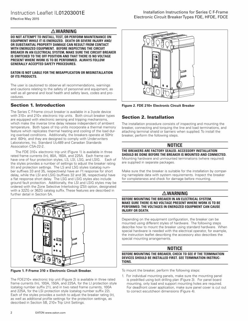
Section 1. IntroductionThe Series C F-frame circuit breaker is available in a 3-pole device with 310+ and 210+ electronic trip units. Both circuit breaker types are equipped with electronic sensing and tripping mechanisms, which make the inverse time delay release independent of ambient temperature. Both types of trip units incorporate a thermal memory feature which replicates thermal heating and cooling of the load dur-ing overload conditions. Additionally, the breakers operate at 50Hz and 60Hz, and they are designed to comply with Underwriters Laboratories, Inc. Standard UL-489 and Canadian Standards Association CSA-22-2.
The FDE 310+ electronic trip unit (Figure 1) is available in three rated frame currents (In), 80A, 160A, and 225A. Each frame can have one of four protection styles, LS, LSI, LSG, and LSIG. Each of the styles provides a number of settings to adjust the breaker rating (Ir) and protection settings. The LS and LSG styles (catalog num-ber suffixes 33 and 35, respectively) have an I2t response for short delay, while the LSI and LSIG (suffixes 32 and 36, respectively) have a flat response short delay. The LSG and LSIG styles also include ground fault protection. Additionally, the LSI and LSIG styles may be ordered with the Zone Selective Interlocking (ZSI) option, designated with a 32ZG or 36ZG catalog suffix. These features are described in further detail in Section 5A.
Figure 1. F-Frame 310 + Electronic Circuit Breaker.
The FDE210+ electronic trip unit (Figure 2) is available in three rated frame currents (In), 100A, 150A, and 225A, for the LI protection style (catalog number suffix 21), and in two rated frame currents, 100A and 225A, for the LSI protection style (catalog number suffix 22). Each of the styles provides a switch to adjust the breaker rating (Ir), as well as additional profile settings for the protection settings, as described in Section 5B, 210+ Trip Unit Settings.
Figure 2. FDE 210+ Electronic Circuit Breaker
Section 2. InstallationThe installation procedure consists of inspecting and mounting the breaker, connecting and torquing the line and load terminations, and attaching terminal shield or barriers when supplied. To install the breaker, perform the following steps.
NOTICETHE BREAKERS ARE FACTORY SEALED. ACCESSORY INSTALLATION SHOULD BE DONE BEFORE THE BREAKER IS MOUNTED AND CONNECTED. Mounting hardware and unmounted terminations (where required) are supplied in separate packages.
Make sure that the breaker is suitable for the installation by compar-ing nameplate data with system requirements. Inspect the breaker for completeness and check for damage before mounting.
DWARNINGBEFORE MOUNTING THE BREAKER IN AN ELECTRICAL SYSTEM, MAKE SURE THERE IS NO VOLTAGE PRESENT WHERE WORK IS TO BE PERFORMED. THE VOLTAGES IN ENERGIZED EQUIPMENT CAN CAUSE INJURY OR DEATH.
Depending on the equipment configuration, the breaker can be mounted using different styles of hardware. The following steps describe how to mount the breaker using standard hardware. When special hardware is needed with the electrical operator, for example, the instruction leaflet describing the accessory also describes the special mounting arrangements.
NOTICEBEFORE MOUNTING THE BREAKER, CHECK TO SEE IF THE TERMINATION DEVICES SHOULD BE INSTALLED FIRST. SEE TERMINATION INSTRUC-TIONS.
To mount the breaker, perform the following steps:
1. For individual mounting panels, make sure the mounting panel is predrilled using bolt drilling plan (Figure 3). For panel board mounting, only load end support mounting holes are required. For deadfront cover application, make sure panel cover is cut out to correct escutcheon dimensions (Figure 4).

3
Instruction Leaflet IL01203001EEffective May 2015
Installation Instructions for Series C F-FrameElectronic Circuit Breaker Types FDE, HFDE, FDCE
EATON www.eaton.com
Figure 3. Breaker Mounting Bolt Drilling Plan.
Figure 4. Breaker Escutcheon Dimensions.
2. If the breaker includes factory installed internal accessories, make sure accessory wiring can be reached when the breaker is mounted.
3. Position the breaker on the mounting surface.
4. Install mounting screws, washers and nuts. Tighten screws firm-ly, but do not exceed 28 pound-inches (3.16 N.m.)
If an optional terminal end cover is to be installed with the breaker (usually line end only), it must be positioned before the cable is con-nected to terminals.
1.375(34,93)
1.375(34,93)
1.375(34,93)
750(19,05)
2.875(73,03)
4.500(11,43)
164-.32 Tap Holes(M4 x .07)
LoadEnd
LineEnd
BreakerHandle
3.40(86,4)
R250(6,35)
Load End
Line End
BreakerHandle
3.40(86,4)
3.64(92,5)
.594(15,09)
2.00(50,98)
.80(20,3)
2.906(73,81)
2.313(58,75)
ø .188(4,78)Hole for access to Push-to-Trip
DCAUTIONWHEN ALUMINUM CONDUCTORS ARE USED, THE APPLICATION OF A SUITABLE JOINT COMPOUND IS RECOMMENDED TO REDUCE THE POSSIBILITY OF TERMINAL OVERHEATING. TERMINAL OVERHEATING CAN CAUSE NUISANCE TRIPPING AND DAMAGE TO THE BREAKER.
After mounting the breaker, line and load terminals and accessory leads should be connected (see accessory schematic diagram on side of breaker).
NOTICEIF TERMINAL SHIELD OR INTERPHASE BARRIERS ARE TO BE INSTALLED ON THE BREAKER, INSTALL THEM AFTER THE TERMINALS ARE CON-NECTED.
• If required, install terminal shield on breaker cover with mounting screws provided.
• If required, install an interphase barrier by sliding barrier into dove-tail grooves between terminals.
• After the breaker is installed, check all mounting hardware and terminal connecting hardware for correct torque loading. Torque values for line/load terminals are provided in Tables 1, 2 and 3.
Table 1. Terminal Types.
Terminal Catalog No.
Terminal Body Material
Screw Head Type
AWG Wire Range
Metric Wire Range
Wire Type
Torque Value lb. in. (N-m)
3TA225FD * Aluminum 3/16Socket Hex
#4-40 25-95 Cu/Al 120 (13.6)
3TA225FDM * Aluminum 5mm Socket Hex
#4-40 25-95 Cu/Al 120 (13.6)
3TA225FDK * † Aluminum 5/16 Socket Hex
#6-300 16-150 Cu/Al 275 (31)
3TA100FD * Aluminum Slotted #14-1/0 2.5-50 Cu/Al See Table 2.
3TA50FB * Aluminum Slotted #14-#4 2.5-16 Cu/Al See Table 2
3T100FB * Steel Slotted #14-1/0 2.5-50 Cu/Al See Table 2
3T150FB * Stainless Steel
Slotted #4-4/0 25-95 Cu only
See Table 2
otee:N Terminal wire connectors are UL listed for standard wire size as defined in UL 486A & UL 486B. * Package of 3. † Individual terminal identified as TA225FD1.
Table 2. Terminal Torque Values of Slotted Head.
Metric Wire Range. Torque Value (N-m) AWG Wire Range Torque Value Lb in.
2.5-6 3.96 #14-10 35
10 4.52 #8 40
16-25 5.06 #6-4 45
35-95 5.65 #3-4/0 50
Table 3. Bolted Connections (Keeper Nut or End Cap).
Termination Catalog No.
Screw Head Type) Nut Thread Size Torque Value Lb in.(N-m)
KPR1A/KPR1AM User Supplied 10-32/M5 35-(4.0)
KPEKxxx Slotted 10-32/M5 35-(4.0)
4
Instruction Leaflet IL01203001EEffective May 2015
Installation Instructions for Series C F-FrameElectronic Circuit Breaker Types FDE, HFDE, FDCE
EATON www.eaton.com
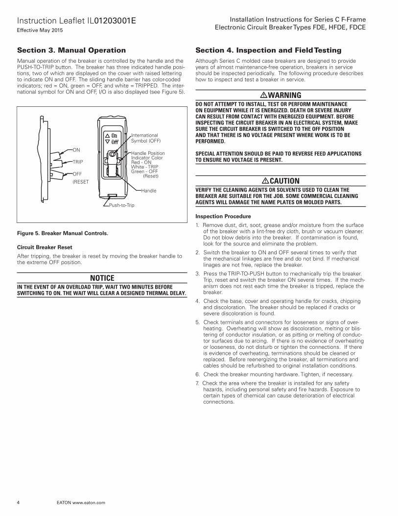
Section 3. Manual OperationManual operation of the breaker is controlled by the handle and the PUSH-TO-TRIP button. The breaker has three indicated handle posi-tions, two of which are displayed on the cover with raised lettering to indicate ON and OFF. The sliding handle barrier has color-coded indicators; red = ON, green = OFF, and white = TRIPPED. The inter-national symbol for ON and OFF, I/O is also displayed (see Figure 5).
Figure 5. Breaker Manual Controls.
Circuit Breaker Reset
After tripping, the breaker is reset by moving the breaker handle to the extreme OFF position.
NOTICEIN THE EVENT OF AN OVERLOAD TRIP, WAIT TWO MINUTES BEFORE SWITCHING TO ON. THE WAIT WILL CLEAR A DESIGNED THERMAL DELAY.
InternationalSymbol (OFF)
Handle PositionIndicator Color Red - ON White - TRIP Green - OFF (Reset)
Handle
Push-to-Trip
ON
TRIP
OFF(RESET)
Section 4. Inspection and Field TestingAlthough Series C molded case breakers are designed to provide years of almost maintenance-free operation, breakers in service should be inspected periodically. The following procedure describes how to inspect and test a breaker in service.
DWARNINGDO NOT ATTEMPT TO INSTALL, TEST OR PERFORM MAINTENANCE ON EQUIPMENT WHILE IT IS ENERGIZED. DEATH OR SEVERE INJURY CAN RESULT FROM CONTACT WITH ENERGIZED EQUIPMENT. BEFORE INSPECTING THE CIRCUIT BREAKER IN AN ELECTRICAL SYSTEM, MAKE SURE THE CIRCUIT BREAKER IS SWITCHED TO THE OFF POSITION AND THAT THERE IS NO VOLTAGE PRESENT WHERE WORK IS TO BE PERFORMED. SPECIAL ATTENTION SHOULD BE PAID TO REVERSE FEED APPLICATIONS TO ENSURE NO VOLTAGE IS PRESENT.
DCAUTIONVERIFY THE CLEANING AGENTS OR SOLVENTS USED TO CLEAN THE BREAKER ARE SUITABLE FOR THE JOB. SOME COMMERCIAL CLEANING AGENTS WILL DAMAGE THE NAME PLATES OR MOLDED PARTS.
Inspection Procedure
1. Remove dust, dirt, soot, grease and/or moisture from the surface of the breaker with a lint-free dry cloth, brush or vacuum cleaner. Do not blow debris into the breaker. If contamination is found, look for the source and eliminate the problem.
2. Switch the breaker to ON and OFF several times to verify that the mechanical linkages are free and do not bind. If mechanical linages are not free, replace the breaker.
3. Press the TRIP-TO-PUSH button to mechanically trip the breaker. Trip, reset and switch the breaker ON several times. If the mech-anism does not rest each time the breaker is tripped, replace the breaker.
4. Check the base, cover and operating handle for cracks, chipping and discoloration. The breaker should be replaced if cracks or severe discoloration is found.
5. Check terminals and connectors for looseness or signs of over-heating. Overheating will show as discoloration, melting or blis-tering of conductor insulation, or as pitting or melting of conduc-tor surfaces due to arcing. If there is no evidence of overheating or looseness, do not disturb or tighten the connections. If there is evidence of overheating, terminations should be cleaned or replaced. Before reenergizing the breaker, all terminations and cables should be refurbished to original installation conditions.
6. Check the breaker mounting hardware. Tighten, if necessary.
7. Check the area where the breaker is installed for any safety hazards, including personal safety and fire hazards. Exposure to certain types of chemical can cause deterioration of electrical connections.
ON
TRIP
OFF
(RESET
International Symbol (OFF)
Handle Position Indicator Color Red - ON White - TRIP Green - OFF (Reset)
Handle
Push-to-Trip

5
Instruction Leaflet IL01203001EEffective May 2015
Installation Instructions for Series C F-FrameElectronic Circuit Breaker Types FDE, HFDE, FDCE
EATON www.eaton.com
Section 5. Trip Unit Controls and FunctionsA. 310+ Trip unit controls and settings (refer to Figures 6 and 7)
Figure 6. Trip Unit Settings for FDE 310+.
STATUS
TEST/ALARM
I IG n(x )GND
Test Port
tLD(s)LONG
ISD (xIr )SHORT
EG
F
H B
DC
IrA
1220
15
242
4
107
68
7
102
3
54
12
NP
O
QJ
K
ML
R
.8 1.0
.2.3
.6.4
tSD/tG (ms)SHORT/GND
I i2
3 1
10
4
5
8
LSIG
LSG
STATUS
TEST/ALARM
I IG n(x )GND
Test Port
tLD(s)LONG
SD r)SHORT
EG
F
H B
DC
A12
2015
242
4
107
68
7
102
3
54
12
.8 1.0
.2.3
.6.4
tG(ms)GND
120
300Inst.
2
3 1
10
4 5
9
6
ISD(xIr)
EG
F
H B
DC
IrA
2
1
10
4 5
9
6
LSI
STATUS
TEST/ALARM
Test Port
tLD(s)LONG
ISD (xIr)SHORT
EG
F
H B
DC
IrA
1220
15
242
4
107
68
7
102
3
54
12
tSD(ms)SHORT
120
300Inst.
2
3 1
10
4 5
7
LS
STATUS
TEST/ALARM
Test Port
tLD(s)LONG
ISD (xIr)SHORT
EG
F
H B
DC
IrA
1220
15
242
4
107
68
7
102
3
54
122
3 1
10
4 5
6
5
8
Figure 7. Breaker Ir Current Setting (A-H), and LSIG Short Delay and Ground Fault Trip Time Delay Settings.
1. Test Port - A test port is built into each trip unit to allow use of a func-tional test kit. The test kit performs a test of the Long Delay, Short Delay and Ground Fault functions. (Plug-In Test Kit Catalog #MTST230V).
2. Test/Alarm LED - A dual function, bi-color (red-amber) LED. It is used as an amber no trip indicator when using the test port. In normal mode, the red LED indicates a high load alarm. For a high load alarm, it will blink ON-OFF if the continuous current is 105% of the Ir setting and is present for a duration over 38 seconds.
3. lr - Continuous current setting - In accordance with standards require-ments, the trip unit initiates a trip of the circuit breaker within 2 hours for an overload of 135% and will trip as a function of l²t for other currents when the load reaches 115% of the set rating. Continuous current values for each lettered (A-H) setting are indicated by the chart displayed on the left side of the trip unit label.
4. tLD - Continuous current overload time delay setting. - The number of seconds required to trip @ 6x Ir. For example, if Ir = 200A, tLD = 2 sec, and load current = 1200A, or 6x Ir, then the breaker will trip in 2 seconds.
5. Isd - Short delay current pick up setting. - Setting in multiples of lr. For short circuit conditions that exceed the short delay pick-up setting, the trip unit initiates a trip after a predetermined delay. Notee: In addition to the short delay trip function, there is a fixed instan-taneous override at 12x In. If a fault current exceeds this override value, the breaker will trip instantaneously (in 20 milliseconds or less).
6. lg - Ground fault current pick-up setting. - It is used on the LSIG and LSG styles to set the ground fault pick-up as a percentage of In (frame current).For example, a 225A frame with an Ig setting of 0.4 will provide a ground fault pick-up at 90A.
7. tsd - Short delay time setting. - For the LSI style, the short delay time is a flat response determined by the tsd switch settings of INST, 120ms, or 300ms. For the LS styles, the short delay time is an I²t function, with a delay of 67ms at an Isd setting of 6x.
8. tsd / tg - Combined short delay and ground fault time delay set-ting. - For the LSIG style, the short delay is a flat response determined by the tsd/tg switch settings of INST, 120ms, or 300ms.This switch is a dual switch that also determines the ground fault time settings of INST, 120ms, or 300ms. For example, if the tsd/tg switch is set at position J, then both short delay time and ground fault time are at INST. As another example, with the tsd/tg switch at position L, the short delay time is INST and the ground fault time is 300ms. The LSIG label (Figure 7) should be used in conjunction with the tsd/tg switch to set any one of nine pos-sible combinations of short delay and ground fault times.
9. tg - Ground fault time delay setting. - For the LSG style, the short delay time is an I²t function while the ground fault flat time is set by the tg switch.
10. Status LED - A green status light indicates the operational status of the trip unit. If the load current exceeds approximately 20% (single phase) or 10% (3-phase) of the maximum current rating of the breaker, (In) of the breaker, the status light will blink ON for one second and OFF for one second.
Ir Settings
80A 160A 225A
A = 15A A = 60A A = 100A
B = 20A B = 70A B = 110A
C = 30A C = 80A C = 125A
D = 40A D = 90A D = 150A
E = 50A E = 100A E = 160A
F = 60A F = 125A F = 175A
G = 70A G = 150A G = 200A
H = 80A = In H = 160A = In H = 225A = In
*Settingstg (ms)
INST 120ms 300ms
tsd (ms)
INST J K L
120ms M N O
300ms P Q R

6
Instruction Leaflet IL01203001EEffective May 2015
Installation Instructions for Series C F-FrameElectronic Circuit Breaker Types FDE, HFDE, FDCE
EATON www.eaton.com
B. 210+ Trip Unit Controls and Settings (refer to Figure 8)
Figure 8. Trip Unit Settings for FDE 210+.
Table 4. Breaker Ir Current Setting (A-G)
Ir Settings
100A 150A 225A
A = 40A A = 70A A = 100A
B = 50A B = 80A B = 110A
C = 60A C = 90A C = 125A
D = 70A D = 100A D = 150A
E = 80A E = 110A E = 175A
F = 90A F = 125A F = 200A
G = 100A = In G = 150A = In G = 225A = In
1. Test Port - A Test Port is built into each trip unit to allow use of a functional test kit (Catalog Number MTST230V). The test kit per-forms a test of the Power-Up, Long Delay, and Short Delay func-tions. The test kit must contain the FDE210+ specific test cable.
2. Status LED - A single LED is used to indicate the operational status of the trip unit. The LED remains OFF with no power or insufficient power. Once the load current exceeds approximately 20A on a single phase or 10A on three phases, the status light will flash ON for one second and OFF for one second. A red flashing light indicates an error condition detected by the unit, and Eaton recommends that the breaker be replaced or serviced as soon as possible.
3. Ir - Continuous current setting. - In accordance with standards requirements, the trip unit initiates a trip of the circuit breaker within two hours for an overload of 135% and will trip as a func-tion of I2t for other currents. Continuous current values for each lettered (A-G) setting are indicated by the chart displayed on the left side of the trip unit label, and in Figure 9. The FDE210+ is designed to enter long delay pickup at 115% of the Ir setting. The response time is fixed at 10sec at 6x Ir current.
4. SD Profile (Isd / tsd) - Short delay protection profile setting. For the LSI protection type, this switch is used to refine the protec-tion settings as shown in Figure 8. The unique profile switch allows for short delay current pickup level and time delay parame-ters to be selected with one switch setting. Each position of the switch offers a typical application group of settings for protection and coordination. The lettered (J-S) settings are indicated by the chart displayed on the right side of the trip unit label.
Notee: In addition to the short delay trip function, there is a fixed instantaneous override at 2400A. If a fault current exceeds this override value, the breaker will trip instantaneously (in 20 milli-seconds or less).
5. Ii - Instantaneous threshold setting. - For LI protection type, this switch is used to select the instantaneous threshold as a multiple of the frame rating (In). The lettered (J-S) settings indicat-ed specific settings, as shown in Figure 8, and are also displayed on the right side of the trip unit label.
C. Other features and options of the FDE 310+
FDE 310+ Zone Selective Interlocking (ZSI) system
The Zone Selective Interlock (ZSI) option provides a wired method of coordinating Upstream and Downstream breakers. Zone Selective Interlocking is active for the short delay and the ground fault delay tripping functions for improved system protection. The 310+ trip unit ZSI feature is compatible with OPTIM and Digitrip trip units, includ-ing all other 310+ models on Series G: (RG, NG LG, JG) and Series C (KD, LD, MDL) breakers and 510 and above models. ZSI, applied correctly, can reduce damage due to circuit or ground fault condi-tions.
Ii Setting Ii (x ln) Level-100A Level-150A Level-225A
J 2 200A 300A 450A
K 2.5 250A 375A 565A
L 3 300A 450A 675A
M 3.5 350A 525A 790A
N 4 400A 600A 900A
O 5 500A 750A 1125A
P 6 600A 900A 1350A
Q 8 800A 1200A 1800A
R 10 1000A 1500A 2250A
S 12 1200A 1800A 2400A*
OVERRIDE 2400A 2400A 2400A
*OVERRIDE
SD Profile Isd (x Ir) tsd (ms)
J 2 150
K 2 300
L 2 I2t
M 4 Inst
N 4 150
O 4 I2t
P 6 Inst
Q 6 300
R 10 150
S 10 300
OVERRIDE 2400
1 2 3 5
1 2 3 4

7
Instruction Leaflet IL01203001EEffective May 2015
Installation Instructions for Series C F-FrameElectronic Circuit Breaker Types FDE, HFDE, FDCE
EATON www.eaton.com
The ZSI feature is a means of communications over a pair of wires between two or more compatible trip units. ZSI will localize the effects of an interruption and provide positive coordination between circuit breakers as a response to different fault conditions and loca-tions. Three wires exit the breaker with the following color code and function:• White/Black Stripe = Zone Out• White/Red Stripe = Zone In• Black = Common
A typical connection for a two breaker system is accomplished by connecting the Zout wire of the downstream breaker to the Zin of the upstream breaker. The common black wires of both breakers must also be connected. An example of a Zone Interlock system would be a 225A FDE breaker used as the upstream breaker and an 80A FDE breaker as the downstream breaker. The Zout wire white/black stripe) of the 80A breaker would be connected to the Zin wire (white/red stripe) of the 225A breaker. Both common wires (black) must be connected . More breakers could be added in a similar fash-ion to form a zone of protection.
If a high fault current is sensed by both the downstream and upstream breakers, the downstream breaker will send an interlock signal to the upstream breaker informing it to restrain from tripping and do its normal timing. This delay allows the downstream breaker to clear the fault without the upstream breaker tripping. However, if for some reason the downstream breaker does not clear the fault the upstream breaker will finish its timing and clear the fault at its setting for tsd or tg time.
To limit the damage during faults, extremely fast tripping times can be achieved using zone selective interlocking to isolate the fault. Table 5 shows the settings of the an upstream and downstream breaker with 310+ trip units with the respective tripping and trip time outcomes of the breakers. Note that the upstream breaker must have a longer time delay than the downstream breaker to accomplish the zone tripping of the downstream (Dn) breaker instead of Both breakers tripping.
Table 5. Settings of Two Breakers Versus the Outcomes.
Upstream
INST 120 ms 300 ms
Dow
nstr
eam INST Both 43 ms Dn 43 ms Dn 43 ms
120 ms Both 52 ms Dn 52 ms Dn 52 ms
300 ms Both 43 ms Dn 43 ms Dn 43 ms
otee:N A single FDE breaker with the Zone Interlocking feature enabled will not trip at the programmed time settings, unless Self Interlocked. To be Self Interlocked, the Zout wire is connected to the Zin wire.
Section 6. Neutral Current Sensor Installa-tion for 310+
Ground fault trip units are supplied from the factory with pigtail lead connections for a neutral current sensor (white and grey wires). Two types of neutral current sensors are available, but must be ordered separately. The two types are as shown in Figures 9 and 10, standard neutral sensors (catalog numbers, CTF080, CTF160, and CTF225 for the respective frames of 80A, 160A, and 225A) and miniature neutral sensors (catalog numbers CTFD080, CTFD160, and CTFD225).
Ground Fault Trip Units detect ground fault currents through Residual Sensing. They are not designed to use source ground or zero sequence ground fault sensing methods. If the system neutral is grounded, but no phase to neutral loads are used, the neutral cur-rent sensor is not necessary. In that case, the white and grey leads on the trip unit should be cut off before installation.
If the system neutral is grounded and phase to neutral loads are used, then the neutral current sensor (see Figure 9) must be used. It should be connected to the breaker. It has the same turns ratio as the phase current sensors in the trip unit sensors in the trip unit.
Figure 9. Neutral Sensor Dimensions (CTF080, CTF160, and CTF225).
+
-
2.188(55.58)
1.094(27.79)
0.618(15.70)
5.610(142.49)
0.618(15.70)
5.860(148.84)
1.000(25.4)
2.000(50.8)
1.440(36.58)
4.374(111.10)
6.000(152.4)
1.170(29.72)
1.188(30.18)
2.188(55.58)
2.438(61.93)
2.330(59.18)3.040(77.22)
3.043(77.29)
Figure 10. Miniature Neutral Sensor Dimensions (CTFD080, CTFD160, and CTFD225).
1.500
.500
.660
1.160
.750
.218
.465
1.190.530
1.225
1.975
.125
.500.500
_ +0.125(3.18)
0.500(12.7)
0.500(12.7)
1.500(38.1)
1.225(31.12)
1.975(50.17)
0.530(13.46)
0.465(11.81)
0.218(5.54)
1.190(30.23)
0.500(12.7)
1.160(29.46)
0.660(16.76)
0.750(19.50)
n .820 I.D.
R.109
POLARITYMARK
POLARITYMARK

Instruction Leaflet IL01203001EEffective May 2015
Installation Instructions for Series C F-FrameElectronic Circuit Breaker Types FDE, HFDE, FDCE
EatonElectrical Sector1000 Eaton BoulevardCleveland Ohio 44122United States877-ETN-CARE (877-386-2273)Eaton.com
© 2015 Eaton CorporationAll Rights ReservedPrinted in USAPublication No. IL01203001E / TBG000539Part No. IL01203001EH09May 2015
NOTICETHE POLARITY OF THE SENSOR CONNECTIONS IS CRITICAL. ALWAYS OBSERVE THE POLARITY MARKINGS ON THE INSTALLATION DRAW-INGS. THE POLARITY MARKINGS ARE IDENTIFIED AS WHITE DOTS ON THE TRANSFORMERS. TO INSURE CORRECT GROUND FAULT EQUIPMENT PERFORMANCE, CONDUCT FIELD TESTS TO COMPLY WITH NATIONAL ELECTRIC CODE REQUIREMENTS UNDER ARTICLE 230-95 (C).
Figure 11. Neutral Sensor Diagram.
Go to www.eaton.com/tcc for the Time Current Curves.
The instructions for installation, testing, maintenance, or repair herein are provided for the use of the product in general commercial applications and may not be appropriate for use in nuclear applica-tions. Additional instructions may be available upon specific request to replace, amend, or supplement these instructions to qualify them for use with the product in safety-related applications in a nuclear facility.
The information, recommendations, descriptions, and safety nota-tions in this document are based on Eaton’s experience and judg-ment with respect to Retrofitting of Power Breakers. This instruction-al literature is published solely for information purposes and should not be considered all-inclusive. If further information is required, you should consult an authorized Eaton sales representative.
The sale of the product shown in this literature is subject to the terms and conditions outlined in appropriate Eaton selling policies or other contractual agreement between the parties. This literature is not intended to and does not enlarge or add to any such contract. The sole source governing the rights and remedies of any purchaser of this equipment is the contract between the purchaser and Eaton.
NO WARRANTIES, EXPRESSED OR IMPLIED, INCLUDING WARRANTIES OF FITNESS FOR A PARTICULAR PURPOSE OR MERCHANTABILITY, OR WARRANTIES ARISING FROM COURSE OF DEALING OR USAGE OF TRADE, ARE MADE REGARDING THE INFORMATION, RECOMMENDATIONS, AND DESCRIPTIONS CONTAINED HEREIN. In no event will Eaton be responsible to the purchaser or user in contract, in tort (including negligence), strict liability or otherwise for any special, indirect, incidental or conse-quential damage or loss whatsoever, including but not limited to damage or loss of use of equipment, plant or power system, cost of capital, loss of power, additional expenses in the use of existing power facilities, or claims against the purchaser or user by its cus-tomers resulting from the use of the information, recommendations and description contained herein.
N
NeutralSensor
Source
White
Grey
+
L C R
Load
Related Documents