Contents Description Page Procedure for identifying parts 2 Customer ordering instructions 2 Distributor ordering instructions 2 Front panel components 3 Breaker pan assembly 4 Breaker pan assembly parts 5 Breaker cubicle components 6 Auxiliary drawers 9 ABB transformers 9 ITI transformers 10 Control power transformers 11 Drawout fuses 12 Auxiliary drawer components 13 Auxiliary cubicle components 14 Bus compartment 15 Bus supports 15 Boots 16 Accessories and miscellaneous parts 17 Technology upgrades 19 Effective August 2011 Supersedes July 2002 Renewal Parts RP02204001E VacClad-W type VCP-W 5 and 15 kV, 36-inch-wide switchgear components

Welcome message from author
This document is posted to help you gain knowledge. Please leave a comment to let me know what you think about it! Share it to your friends and learn new things together.
Transcript

ContentsDescription Page
Procedure for identifying parts . . . . . . . . . . . . . . . 2Customer ordering instructions . . . . . . . . . . . . . . . 2Distributor ordering instructions . . . . . . . . . . . . . . 2Front panel components . . . . . . . . . . . . . . . . . . . . . 3Breaker pan assembly . . . . . . . . . . . . . . . . . . . . . . 4Breaker pan assembly parts . . . . . . . . . . . . . . . . . 5Breaker cubicle components . . . . . . . . . . . . . . . . . 6Auxiliary drawers . . . . . . . . . . . . . . . . . . . . . . . . . . 9
ABB transformers . . . . . . . . . . . . . . . . . . . . . . . 9ITI transformers . . . . . . . . . . . . . . . . . . . . . . . . 10Control power transformers . . . . . . . . . . . . . . . 11Drawout fuses . . . . . . . . . . . . . . . . . . . . . . . . . 12
Auxiliary drawer components . . . . . . . . . . . . . . . 13Auxiliary cubicle components . . . . . . . . . . . . . . . 14Bus compartment . . . . . . . . . . . . . . . . . . . . . . . . 15
Bus supports . . . . . . . . . . . . . . . . . . . . . . . . . . 15Boots . . . . . . . . . . . . . . . . . . . . . . . . . . . . . . . . 16
Accessories and miscellaneous parts . . . . . . . . . 17Technology upgrades . . . . . . . . . . . . . . . . . . . . . . 19
Effective August 2011Supersedes July 2002Renewal Parts RP02204001E
VacClad-W type VCP-W 5 and 15 kV, 36-inch-wide switchgear components
2
Renewal Parts RP02204001EEffective August 2011
VacClad-W type VCP-W 5 and 15 kV, 36-inch-wide switchgear components
EATON CORPORATION www.eaton.com
Procedure for identifying parts
1. Refer to the listing below and turn to the proper section in this book to identify standard parts and components.
Front panel components . . . . . . . . . . . . . . . . . . . . . . . . . . . . . . . 3Breaker pan assembly . . . . . . . . . . . . . . . . . . . . . . . . . . . . . . . . . 4Breaker pan assembly parts . . . . . . . . . . . . . . . . . . . . . . . . . . . . 5Breaker cubicle components . . . . . . . . . . . . . . . . . . . . . . . . . . . . 6Auxiliary drawers . . . . . . . . . . . . . . . . . . . . . . . . . . . . . . . . . . . . . 9
ABB transformers . . . . . . . . . . . . . . . . . . . . . . . . . . . . . . . . . . 9ITI transformers . . . . . . . . . . . . . . . . . . . . . . . . . . . . . . . . . . . 10Control power transformers . . . . . . . . . . . . . . . . . . . . . . . . . 11Drawout fuses . . . . . . . . . . . . . . . . . . . . . . . . . . . . . . . . . . . . 12
Auxiliary drawer components . . . . . . . . . . . . . . . . . . . . . . . . . . 13Auxiliary cubicle components . . . . . . . . . . . . . . . . . . . . . . . . . . 14Bus compartment . . . . . . . . . . . . . . . . . . . . . . . . . . . . . . . . . . . 15
Bus supports . . . . . . . . . . . . . . . . . . . . . . . . . . . . . . . . . . . . . 15Boots . . . . . . . . . . . . . . . . . . . . . . . . . . . . . . . . . . . . . . . . . . . 16
Accessories and miscellaneous parts . . . . . . . . . . . . . . . . . . . . 17Technology upgrades . . . . . . . . . . . . . . . . . . . . . . . . . . . . . . . . . 19
2. This book identifies those replacement parts that are most frequently ordered and that are readily available. These parts should be ordered by style number or catalog number to speed up processing and delivery.
This Renewal Parts Data applies to the housing parts only. For the vacuum circuit breaker parts, refer to Price List 33-729.
Customer ordering instructions
1. Specify the part by style or catalog number, description and quantity required.
2. Contact your local Eaton sales office or authorized Eaton distributor.
Distributor ordering instructions
1. Specify quantity and enter the order on Vista by style or catalog number. Contact the Aftermarket Products Center (APC) in Greenwood, SC, at 800-345-4072 when ordering relay covers.
2. Contact APC for availability at 800-345-4072.
m WARNINGHAZARDOUS VOLTAGE WILL CAUSE SEVERE INJURY OR DEATH. TURN OFF POWER SUPPLY TO EQUIPMENT BEFORE WORKING ON IT.
3
Renewal Parts RP02204001EEffective August 2011
VacClad-W type VCP-W 5 and 15 kV, 36-inch-wide switchgear components
EATON CORPORATION www.eaton.com
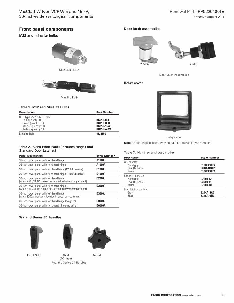
Front panel componentsM22 and minalite bulbs
M22 Bulb (LED)
Minalite Bulb
Table 1. M22 and Minalite Bulbs
Description Part Number
LED, Type M22 (48V, 10 mA) Red (quantity 10) Green (quantity 10) Yellow (quantity 10) Amber (quantity 10)
M22-L-R-RM22-L-G-GM22-L-Y-WM22-L-A-W
Minalite bulb 1124156
Table 2. Blank Front Panel (Includes Hinges and Standard Door Latches)
Panel Description Style Number
36-inch upper panel with left-hand hinge A1000L36-inch upper panel with right-hand hinge A1000R36-inch lower panel with left-hand hinge (1200A breaker) B1000L36-inch lower panel with right-hand hinge (1200A breaker) B1000R36-inch lower panel with left-hand hinge (when 2000/3000A breaker is located in lower compartment)
B2000L
36-inch lower panel with right-hand hinge (when 2000/3000A breaker is located in lower compartment)
B2000R
36-inch lower panel with left-hand hinge (when 3000A breaker is located in upper compartment)
B3000L
36-inch lower panel with left-hand hinge (no grille) B0000L36-inch lower panel with right-hand hinge (no grille) B0000R
W2 and Series 24 handles
W2 and Series 24 Handles
Door latch assemblies
Door Latch Assemblies
Relay cover
Relay Cover
otee:N Order by description . Provide type of relay and style number .
Table 3. Handles and assemblies
Description Style Number
W2 handles Pistol grip Oval (T-Shape) Round
310C624H02501B787H01310C624H01
Series 24 handles Pistol grip Oval (T-Shape) Round
02000-1202000-1102000-10
Door latch assemblies Gray Black
8244A12G018346A76H01
Pistol Grip Oval (T-Shape)
Round
BlackGray
4
Renewal Parts RP02204001EEffective August 2011
VacClad-W type VCP-W 5 and 15 kV, 36-inch-wide switchgear components
EATON CORPORATION www.eaton.com
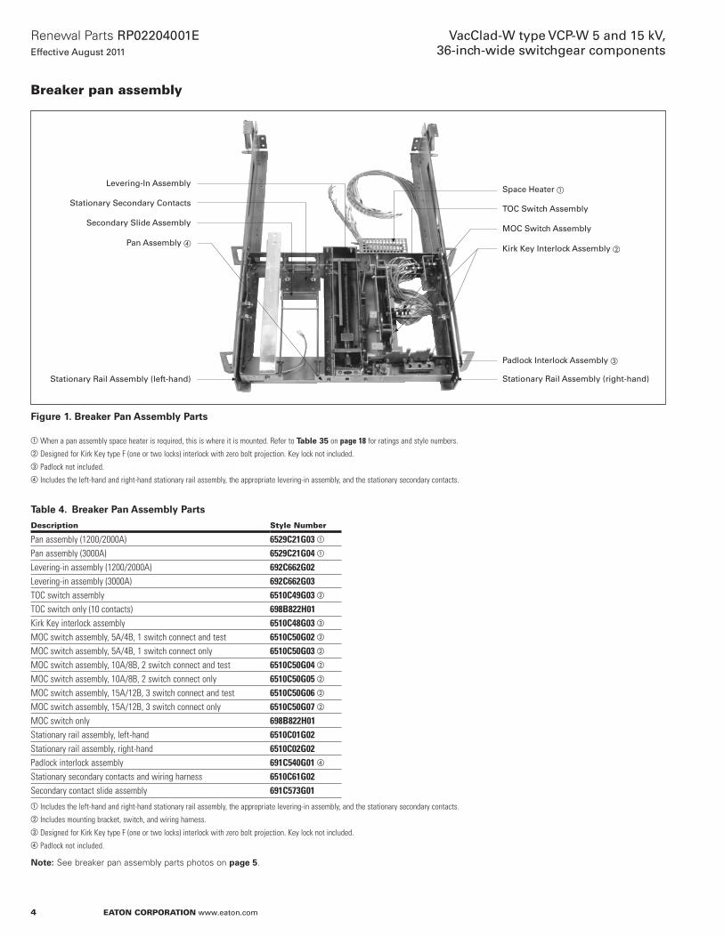
Breaker pan assembly
Space Heater �
TOC Switch Assembly
MOC Switch Assembly
Kirk Key Interlock Assembly �
Padlock Interlock Assembly �
Stationary Rail Assembly (right-hand)
Levering-In Assembly
Stationary Secondary Contacts
Secondary Slide Assembly
Pan Assembly �
Stationary Rail Assembly (left-hand)
Figure 1. Breaker Pan Assembly Parts
aWhen a pan assembly space heater is required, this is where it is mounted. Refer to Table 35 on page 18 for ratings and style numbers.bDesigned for Kirk Key type F (one or two locks) interlock with zero bolt projection. Key lock not included.cPadlock not included.d Includes the left-hand and right-hand stationary rail assembly, the appropriate levering-in assembly, and the stationary secondary contacts.
Table 4. Breaker Pan Assembly Parts
Description Style Number
Pan assembly (1200/2000A) 6529C21G03 a
Pan assembly (3000A) 6529C21G04 a
Levering-in assembly (1200/2000A) 692C662G02Levering-in assembly (3000A) 692C662G03TOC switch assembly 6510C49G03 b
TOC switch only (10 contacts) 698B822H01Kirk Key interlock assembly 6510C48G03 c
MOC switch assembly, 5A/4B, 1 switch connect and test 6510C50G02 b
MOC switch assembly, 5A/4B, 1 switch connect only 6510C50G03 b
MOC switch assembly, 10A/8B, 2 switch connect and test 6510C50G04 b
MOC switch assembly, 10A/8B, 2 switch connect only 6510C50G05 b
MOC switch assembly, 15A/12B, 3 switch connect and test 6510C50G06 b
MOC switch assembly, 15A/12B, 3 switch connect only 6510C50G07 b
MOC switch only 698B822H01Stationary rail assembly, left-hand 6510C01G02Stationary rail assembly, right-hand 6510C02G02Padlock interlock assembly 691C540G01 d
Stationary secondary contacts and wiring harness 6510C61G02Secondary contact slide assembly 691C573G01a Includes the left-hand and right-hand stationary rail assembly, the appropriate levering-in assembly, and the stationary secondary contacts.b Includes mounting bracket, switch, and wiring harness.cDesigned for Kirk Key type F (one or two locks) interlock with zero bolt projection. Key lock not included.dPadlock not included.
otee:N See breaker pan assembly parts photos on page 5 .
5
Renewal Parts RP02204001EEffective August 2011
VacClad-W type VCP-W 5 and 15 kV, 36-inch-wide switchgear components
EATON CORPORATION www.eaton.com
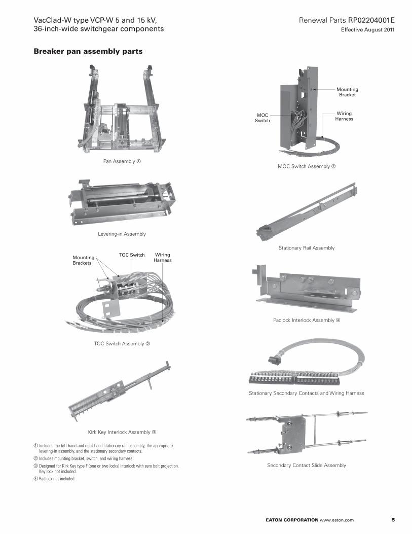
Breaker pan assembly parts
Pan Assembly a
Levering-in Assembly
Mounting Brackets
TOC Switch Wiring Harness
TOC Switch Assembly b
Kirk Key Interlock Assembly c
a Includes the left-hand and right-hand stationary rail assembly, the appropriate levering-in assembly, and the stationary secondary contacts.
b Includes mounting bracket, switch, and wiring harness.cDesigned for Kirk Key type F (one or two locks) interlock with zero bolt projection.
Key lock not included.dPadlock not included.
Mounting Bracket
Wiring Harness
MOC Switch
MOC Switch Assembly b
Stationary Rail Assembly
Padlock Interlock Assembly d
Stationary Secondary Contacts and Wiring Harness
Secondary Contact Slide Assembly

6
Renewal Parts RP02204001EEffective August 2011
VacClad-W type VCP-W 5 and 15 kV, 36-inch-wide switchgear components
EATON CORPORATION www.eaton.com
Breaker cubicle components
Stab Molding Assembly
otee:N Each style provides for three poles of a breaker . Bus side is defined as the bottom poles of a breaker mounted in the top location, and the top poles of a breaker mounted in the bottom location . Line side is defined as the top poles of a breaker mounted in the top location, and the bottom poles of a breaker mounted in the bottom location . Glass polyester insulation is standard .
CT Barrier Mounting Kit
Shutter Assembly
Table 5. Stab Molding Assembly a
Description Application Style Number
1200A porcelain Bus side 6437C76G012000A porcelain Bus side 6437C76G033000A porcelain Bus side 6355C65G021200A glass polyester Bus side 6437C76G052000A glass polyester Bus side 6437C76G073000A glass polyester Bus side 6355C65G031200A porcelain Line side 6437C76G022000A porcelain Line side 6437C76G043000A porcelain Line side 6455C65G021200A glass polyester Line side 6437C76G062000A glass polyester Line side 6437C76G083000A glass polyester Line side 6355C65G03aEach style provides for three poles of a breaker. Bus side is defined as the bottom poles of
a breaker mounted in the top location, and the top poles of a breaker mounted in the bottom location. Line side is defined as the top poles of a breaker mounted in the top location, and the bottom poles of a breaker mounted in the bottom location. Glass polyester insulation is standard.
Table 6. Mounting Kits and Assemblies
Description Style Number
CT barrier mounting kit 3A38291G01Shutter assembly 6529C22G01

7
Renewal Parts RP02204001EEffective August 2011
VacClad-W type VCP-W 5 and 15 kV, 36-inch-wide switchgear components
EATON CORPORATION www.eaton.com
CT Mounting Hardware Kit
Current Transformers Mounted on Stab Molding Assembly
otee:N Each pole can accommodate up to two standard-accuracy CTs or one high-accuracy CT .
Zero Sequence CT
Table 7. Current Transformer Mounting Hardware Kit
Description Style Number
With no CTs 3A38292G01 a
With one type ABB SCV or ITI 780/pole 3A38292G02 a
With two type ABB SCV or ITI 780/pole 3A38292G03 a
With one type ABB SCV-D or ITI 785/pole 3A38292G04 a
With one type ABB BYZ or ITI 143 3A38292G05aUsed for mounting to stab molding assembly (see page 6).
Table 8. ABB Current Transformers a
Ratio Accuracy Class Style Number
Type SCV Narrow Profile Standard Accuracy100/5 C10 6353C88H01150/5 C20 6353C88H02200/5 C20 6353C88H03250/5 C20 6353C88H04300/5 C20 6353C88H05400/5 C50 6353C88H06500/5 C50 6353C88H07600/5 C100 6353C88H08600/5 (MR) C100 6350C23H01800/5 C100 6353C88H091000/5 C100 6353C88H101200/5 C200 6353C88H111200/5 (MR) C200 6350C24H011500/5 C200 6353C88H122000/5 C200 6353C88H132000/5 (MR) C200 6350C25H012500/5 C200 6353C88H143000/5 C200 6353C88H153000/5 (MR) C200 6350C26H014000/5 C200 6353C88H164000/5 (MR) C200 6350C27H01Type SCV-D Thick Profile High Accuracy50/5 C10 6353C89H0175/5 C20 6353C89H02100/5 C20 6353C89H03150/5 C50 6353C89H04200/5 C50 6353C89H05250/5 C50 6353C89H06300/5 C100 6353C89H07400/5 C100 6353C89H08500/5 C200 6353C89H09600/5 C200 6353C89H10600/5 (MR) C200 6436C46H01800/5 C200 6353C89H111000/5 C200 6353C89H121200/5 C400 6353C89H131200/5 (MR) C400 6436C47H011500/5 C400 6353C89H142000/5 C400 6353C89H152000/5 (MR) C400 6436C48H012500/5 C400 6353C89H163000/5 C400 6353C89H173000/5 (MR) C400 6436C49H014000/5 C400 6353C89H184000/5 (MR) C400 6436C50H01aEach pole can accommodate up to two standard-accuracy CTs or one high-accuracy CT.
otee:N (MR) = Multi-ratio transformers .
Table 9. Type ABB BYZ Zero Sequence CT
Ratio Accuracy Class Style Number
50/5 C10 6353C97H01100/5 C20 6353C97H02
8
Renewal Parts RP02204001EEffective August 2011
VacClad-W type VCP-W 5 and 15 kV, 36-inch-wide switchgear components
EATON CORPORATION www.eaton.com
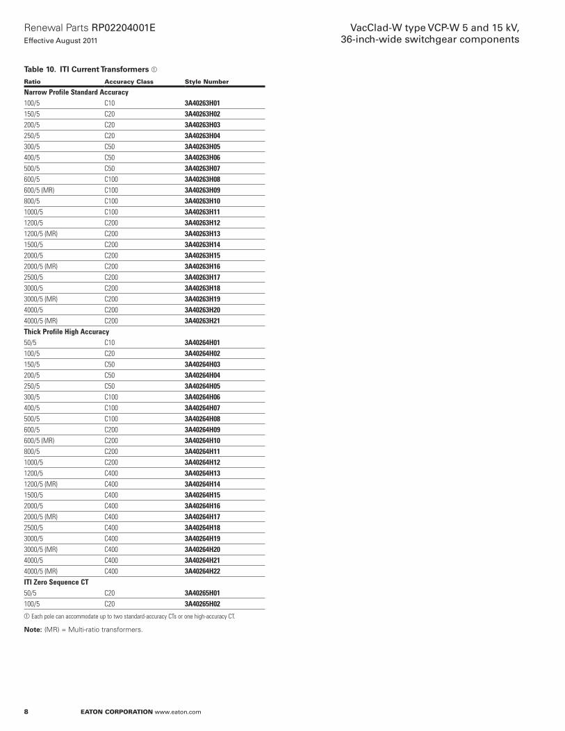
Table 10. ITI Current Transformers a
Ratio Accuracy Class Style Number
Narrow Profile Standard Accuracy100/5 C10 3A40263H01150/5 C20 3A40263H02200/5 C20 3A40263H03250/5 C20 3A40263H04300/5 C50 3A40263H05400/5 C50 3A40263H06500/5 C50 3A40263H07600/5 C100 3A40263H08600/5 (MR) C100 3A40263H09800/5 C100 3A40263H101000/5 C100 3A40263H111200/5 C200 3A40263H121200/5 (MR) C200 3A40263H131500/5 C200 3A40263H142000/5 C200 3A40263H152000/5 (MR) C200 3A40263H162500/5 C200 3A40263H173000/5 C200 3A40263H183000/5 (MR) C200 3A40263H194000/5 C200 3A40263H204000/5 (MR) C200 3A40263H21Thick Profile High Accuracy50/5 C10 3A40264H01100/5 C20 3A40264H02150/5 C50 3A40264H03200/5 C50 3A40264H04250/5 C50 3A40264H05300/5 C100 3A40264H06400/5 C100 3A40264H07500/5 C100 3A40264H08600/5 C200 3A40264H09600/5 (MR) C200 3A40264H10800/5 C200 3A40264H111000/5 C200 3A40264H121200/5 C400 3A40264H131200/5 (MR) C400 3A40264H141500/5 C400 3A40264H152000/5 C400 3A40264H162000/5 (MR) C400 3A40264H172500/5 C400 3A40264H183000/5 C400 3A40264H193000/5 (MR) C400 3A40264H204000/5 C400 3A40264H214000/5 (MR) C400 3A40264H22ITI Zero Sequence CT50/5 C20 3A40265H01100/5 C20 3A40265H02aEach pole can accommodate up to two standard-accuracy CTs or one high-accuracy CT.
otee:N (MR) = Multi-ratio transformers .
9
Renewal Parts RP02204001EEffective August 2011
VacClad-W type VCP-W 5 and 15 kV, 36-inch-wide switchgear components
EATON CORPORATION www.eaton.com
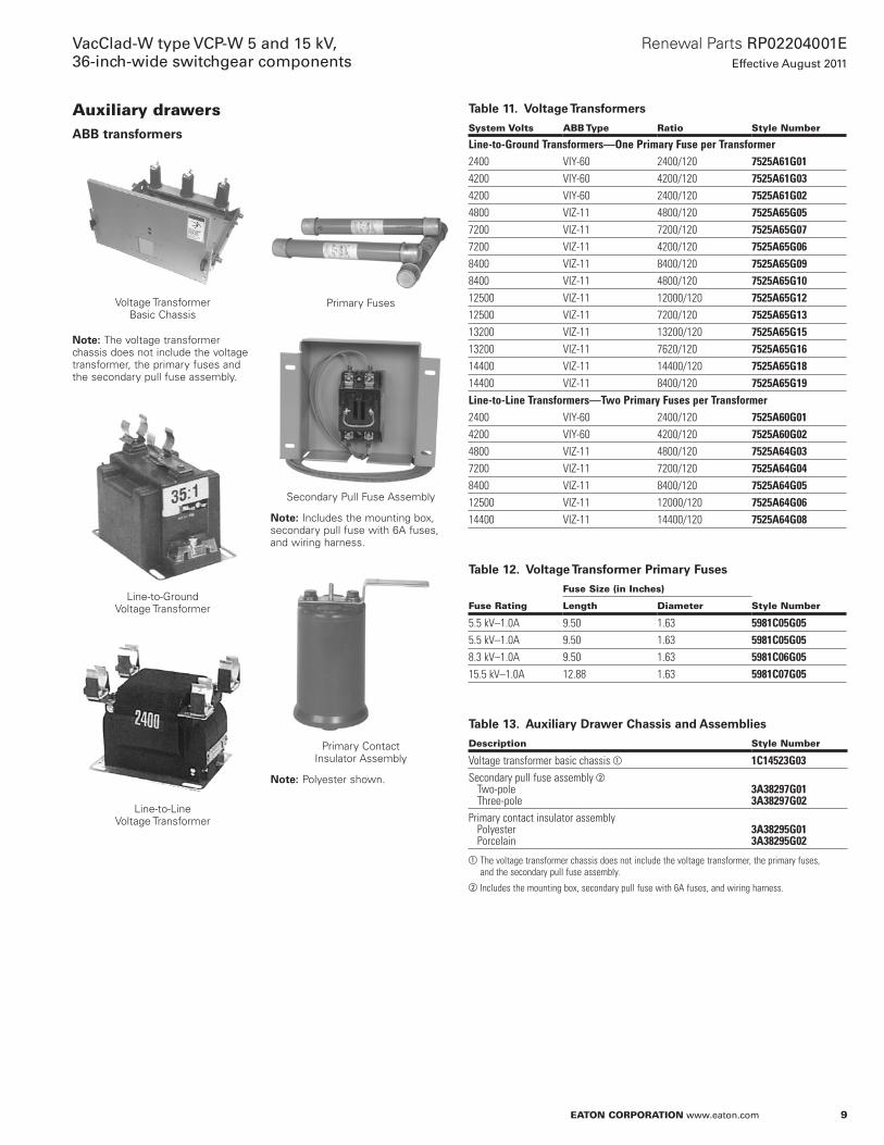
Auxiliary drawersABB transformers
Voltage Transformer Basic Chassis
otee:N The voltage transformer chassis does not include the voltage transformer, the primary fuses and the secondary pull fuse assembly .
Line-to-Ground Voltage Transformer
Line-to-Line Voltage Transformer
Primary Fuses
Secondary Pull Fuse Assembly
otee:N Includes the mounting box, secondary pull fuse with 6A fuses, and wiring harness .
Primary Contact Insulator Assembly
otee:N Polyester shown .
Table 11. Voltage Transformers
System Volts ABB Type Ratio Style Number
Line-to-Ground Transformers—One Primary Fuse per Transformer2400 VIY-60 2400/120 7525A61G014200 VIY-60 4200/120 7525A61G034200 VIY-60 2400/120 7525A61G024800 VIZ-11 4800/120 7525A65G057200 VIZ-11 7200/120 7525A65G077200 VIZ-11 4200/120 7525A65G068400 VIZ-11 8400/120 7525A65G098400 VIZ-11 4800/120 7525A65G1012500 VIZ-11 12000/120 7525A65G1212500 VIZ-11 7200/120 7525A65G1313200 VIZ-11 13200/120 7525A65G1513200 VIZ-11 7620/120 7525A65G1614400 VIZ-11 14400/120 7525A65G1814400 VIZ-11 8400/120 7525A65G19Line-to-Line Transformers—Two Primary Fuses per Transformer2400 VIY-60 2400/120 7525A60G014200 VIY-60 4200/120 7525A60G024800 VIZ-11 4800/120 7525A64G037200 VIZ-11 7200/120 7525A64G048400 VIZ-11 8400/120 7525A64G0512500 VIZ-11 12000/120 7525A64G0614400 VIZ-11 14400/120 7525A64G08
Table 12. Voltage Transformer Primary Fuses
Fuse Rating
Fuse Size (in Inches)
Style NumberLength Diameter
5.5 kV–1.0A 9.50 1.63 5981C05G055.5 kV–1.0A 9.50 1.63 5981C05G058.3 kV–1.0A 9.50 1.63 5981C06G0515.5 kV–1.0A 12.88 1.63 5981C07G05
Table 13. Auxiliary Drawer Chassis and Assemblies
Description Style Number
Voltage transformer basic chassis a 1C14523G03Secondary pull fuse assembly b Two-pole Three-pole
3A38297G013A38297G02
Primary contact insulator assembly Polyester Porcelain
3A38295G013A38295G02
aThe voltage transformer chassis does not include the voltage transformer, the primary fuses, and the secondary pull fuse assembly.
b Includes the mounting box, secondary pull fuse with 6A fuses, and wiring harness.

10
Renewal Parts RP02204001EEffective August 2011
VacClad-W type VCP-W 5 and 15 kV, 36-inch-wide switchgear components
EATON CORPORATION www.eaton.com
ITI transformers
ITI Line-to-Line PT Plate Assemblies
ITI Line-to-Ground PT Plate Assemblies
Table 14. VCP-W Line-to-Line Transformers Mounting Plate Assembly—Including PTs and Stabs—ITI Voltage Transformers (Two Primary Fuses per Transformer)
System Line-to-Line Volts
ITI Type Ratio
Style Number
2400 PTW3 2400/120 1C17638G014200 PTW3 4200/120 1C17638G024800 PTW5 4800/120 1C17639G017200 PTW5 7200/120 1C17639G028400 PTW5 8400/120 1C17639G0312500 PTW5 12000/120 1C17639G0413200 PTW5 13200/120 1C17639G0514400 PTW5 14400/120 1C17639G06
Table 15. Line-to-Line Transformers (Two Primary Fuses per Transformer) Includes PT Only—Fuses, Fuse Clips, and the Mounting Plate Assembly Are Not Included
System Line-to-Line Volts
ITI Type Ratio
Style Number
2400 PTW3 2400/120 3A40266H014200 PTW3 4200/120 3A40266H024800 PTW5 4800/120 3A40266H037200 PTW5 7200/120 3A40266H048400 PTW5 8400/120 3A40266H0512500 PTW5 12000/120 3A40266H0613200 PTW5 13200/120 3A40266H0714400 PTW5 14400/120 3A40266H08
Table 16. VCP-W Line-to-Ground Transformers Mounting Plate Assembly—Including PTs and Stabs—ITI Voltage Transformers (One Primary Fuse per Transformer)
System Line-to-Line Volts
ITI Type Ratio
Style Number
2400 PTW3 2400/120 1C17613G014200 PTW3 4200/120 1C17613G024200 PTW3 2400/120 1C17613G044800 PTW5 4800/120 Contact factory7200 PTW5 7200/120 1C17654G017200 PTW5 4200/120 1C17614G018400 PTW5 8400/120 1C17654G028400 PTW5 4800/120 1C17614G0212500 PTW5 12000/120 1C17654G0312500 PTW5 7200/120 1C17614G0313200 PTW5 13200/120 1C17654G0413200 PTW5 7620/120 1C17614G0414400 PTW5 14400/120 1C17654G0514400 PTW5 8400/120 1C17614G05
Table 17. Line-to-Ground Transformers (One Primary Fuse per Transformer) Includes PT Only—Fuses, Fuse Clips, and the Mounting Plate Assembly Are Not Included
System Line-to-Line Volts
ITI Type Ratio
Style Number
2400 PTW3 2400/120 3A40267H014200 PTW3 4200/120 3A40267H024200 PTW3 2400/120 3A40267H034800 PTW5 4800/120 Contact factory7200 PTW5 7200/120 3A40267H057200 PTW5 4200/120 3A40267H068400 PTW5 8400/120 3A40267H078400 PTW5 4800/120 3A40267H0812500 PTW5 12000/120 3A40267H0912500 PTW5 7200/120 3A40267H1013200 PTW5 13200/120 3A40267H1113200 PTW5 7620/120 3A40267H1214400 PTW5 14400/120 3A40267H1314400 PTW5 8400/120 3A40267H14
otee:N Please contact the factory for part numbers and pricing for replacement parts included in the ITI mounting plate assemblies .
11
Renewal Parts RP02204001EEffective August 2011
VacClad-W type VCP-W 5 and 15 kV, 36-inch-wide switchgear components
EATON CORPORATION www.eaton.com
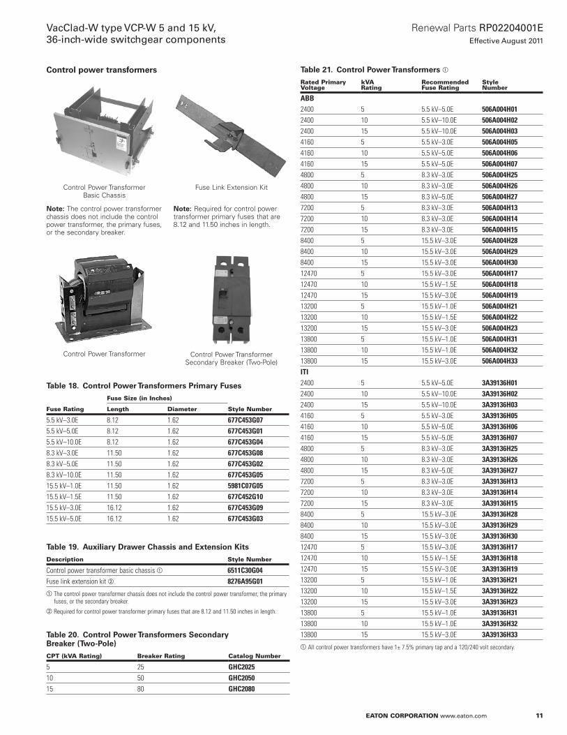
Control power transformers
Control Power Transformer Basic Chassis
otee:N The control power transformer chassis does not include the control power transformer, the primary fuses, or the secondary breaker .
Control Power Transformer
Fuse Link Extension Kit
otee:N Required for control power transformer primary fuses that are 8 .12 and 11 .50 inches in length .
Control Power Transformer Secondary Breaker (Two-Pole)
Table 18. Control Power Transformers Primary Fuses
Fuse Rating
Fuse Size (in Inches)
Style NumberLength Diameter
5.5 kV–3.0E 8.12 1.62 677C453G075.5 kV–5.0E 8.12 1.62 677C453G015.5 kV–10.0E 8.12 1.62 677C453G048.3 kV–3.0E 11.50 1.62 677C453G088.3 kV–5.0E 11.50 1.62 677C453G028.3 kV–10.0E 11.50 1.62 677C453G0515.5 kV–1.0E 11.50 1.62 5981C07G0515.5 kV–1.5E 11.50 1.62 677C452G1015.5 kV–3.0E 16.12 1.62 677C453G0915.5 kV–5.0E 16.12 1.62 677C453G03
Table 19. Auxiliary Drawer Chassis and Extension Kits
Description Style Number
Control power transformer basic chassis a 6511C30G04Fuse link extension kit b 8276A95G01aThe control power transformer chassis does not include the control power transformer, the primary
fuses, or the secondary breaker.bRequired for control power transformer primary fuses that are 8.12 and 11.50 inches in length.
Table 20. Control Power Transformers Secondary Breaker (Two-Pole)
CPT (kVA Rating) Breaker Rating Catalog Number
5 25 GHC202510 50 GHC205015 80 GHC2080
Table 21. Control Power Transformers a
Rated Primary Voltage
kVA Rating
Recommended Fuse Rating
Style Number
ABB2400 5 5.5 kV–5.0E 506A004H012400 10 5.5 kV–10.0E 506A004H022400 15 5.5 kV–10.0E 506A004H034160 5 5.5 kV–3.0E 506A004H054160 10 5.5 kV–5.0E 506A004H064160 15 5.5 kV–5.0E 506A004H074800 5 8.3 kV–3.0E 506A004H254800 10 8.3 kV–3.0E 506A004H264800 15 8.3 kV–5.0E 506A004H277200 5 8.3 kV–3.0E 506A004H137200 10 8.3 kV–3.0E 506A004H147200 15 8.3 kV–3.0E 506A004H158400 5 15.5 kV–3.0E 506A004H288400 10 15.5 kV–3.0E 506A004H298400 15 15.5 kV–3.0E 506A004H3012470 5 15.5 kV–3.0E 506A004H1712470 10 15.5 kV–1.5E 506A004H1812470 15 15.5 kV–3.0E 506A004H1913200 5 15.5 kV–1.0E 506A004H2113200 10 15.5 kV–1.5E 506A004H2213200 15 15.5 kV–3.0E 506A004H2313800 5 15.5 kV–1.0E 506A004H3113800 10 15.5 kV–1.0E 506A004H3213800 15 15.5 kV–3.0E 506A004H33ITI2400 5 5.5 kV–5.0E 3A39136H012400 10 5.5 kV–10.0E 3A39136H022400 15 5.5 kV–10.0E 3A39136H034160 5 5.5 kV–3.0E 3A39136H054160 10 5.5 kV–5.0E 3A39136H064160 15 5.5 kV–5.0E 3A39136H074800 5 8.3 kV–3.0E 3A39136H254800 10 8.3 kV–3.0E 3A39136H264800 15 8.3 kV–5.0E 3A39136H277200 5 8.3 kV–3.0E 3A39136H137200 10 8.3 kV–3.0E 3A39136H147200 15 8.3 kV–3.0E 3A39136H158400 5 15.5 kV–3.0E 3A39136H288400 10 15.5 kV–3.0E 3A39136H298400 15 15.5 kV–3.0E 3A39136H3012470 5 15.5 kV–3.0E 3A39136H1712470 10 15.5 kV–1.5E 3A39136H1812470 15 15.5 kV–3.0E 3A39136H1913200 5 15.5 kV–1.0E 3A39136H2113200 10 15.5 kV–1.5E 3A39136H2213200 15 15.5 kV–3.0E 3A39136H2313800 5 15.5 kV–1.0E 3A39136H3113800 10 15.5 kV–1.0E 3A39136H3213800 15 15.5 kV–3.0E 3A39136H33aAll control power transformers have 1± 7.5% primary tap and a 120/240 volt secondary.
12
Renewal Parts RP02204001EEffective August 2011
VacClad-W type VCP-W 5 and 15 kV, 36-inch-wide switchgear components
EATON CORPORATION www.eaton.com
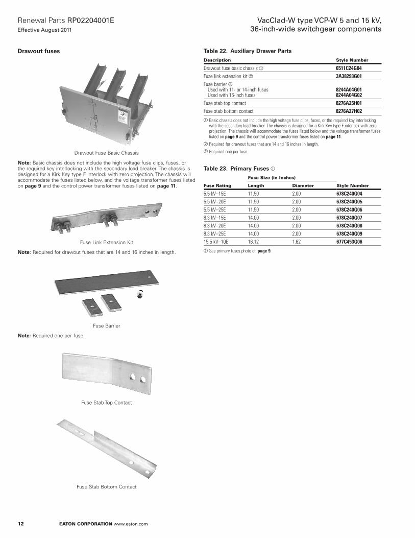
Drawout fuses
Drawout Fuse Basic Chassis
otee:N Basic chassis does not include the high voltage fuse clips, fuses, or the required key interlocking with the secondary load breaker . The chassis is designed for a Kirk Key type F interlock with zero projection . The chassis will accommodate the fuses listed below, and the voltage transformer fuses listed on page 9 and the control power transformer fuses listed on page 11 .
Fuse Link Extension Kit
otee:N Required for drawout fuses that are 14 and 16 inches in length .
Fuse Barrier
otee:N Required one per fuse .
Fuse Stab Top Contact
Fuse Stab Bottom Contact
Table 22. Auxiliary Drawer Parts
Description Style Number
Drawout fuse basic chassis a 6511C24G04Fuse link extension kit b 3A38293G01Fuse barrier c Used with 11- or 14-inch fuses Used with 16-inch fuses
8244A04G018244A04G02
Fuse stab top contact 8276A25H01Fuse stab bottom contact 8276A27H02aBasic chassis does not include the high voltage fuse clips, fuses, or the required key interlocking
with the secondary load breaker. The chassis is designed for a Kirk Key type F interlock with zero projection. The chassis will accommodate the fuses listed below and the voltage transformer fuses listed on page 9 and the control power transformer fuses listed on page 11.
bRequired for drawout fuses that are 14 and 16 inches in length.cRequired one per fuse.
Table 23. Primary Fuses a
Fuse Rating
Fuse Size (in Inches)
Style NumberLength Diameter
5.5 kV–15E 11.50 2.00 678C240G045.5 kV–20E 11.50 2.00 678C240G055.5 kV–25E 11.50 2.00 678C240G068.3 kV–15E 14.00 2.00 678C240G078.3 kV–20E 14.00 2.00 678C240G088.3 kV–25E 14.00 2.00 678C240G0915.5 kV–10E 16.12 1.62 677C453G06aSee primary fuses photo on page 9.

13
Renewal Parts RP02204001EEffective August 2011
VacClad-W type VCP-W 5 and 15 kV, 36-inch-wide switchgear components
EATON CORPORATION www.eaton.com
Auxiliary drawer components
Fuse Clip Mounting Kit
Bearing Wheel Assembly
Chassis Handle
Male Secondary Contact Assembly
Table 24. Auxiliary Drawer Components
Description Style Number
Fuse clip mounting kit Drawout fuse chassis (1.62 fuse diameter) Drawout fuse chassis (2.00 fuse diameter) CPT chassis (1.62 fuse diameter)
3A38296G013A38296G023A38296G03
Bearing wheel assembly 3A38294G01Chassis handle 8341A34H01Male secondary contact assembly 6511C08G02
14
Renewal Parts RP02204001EEffective August 2011
VacClad-W type VCP-W 5 and 15 kV, 36-inch-wide switchgear components
EATON CORPORATION www.eaton.com
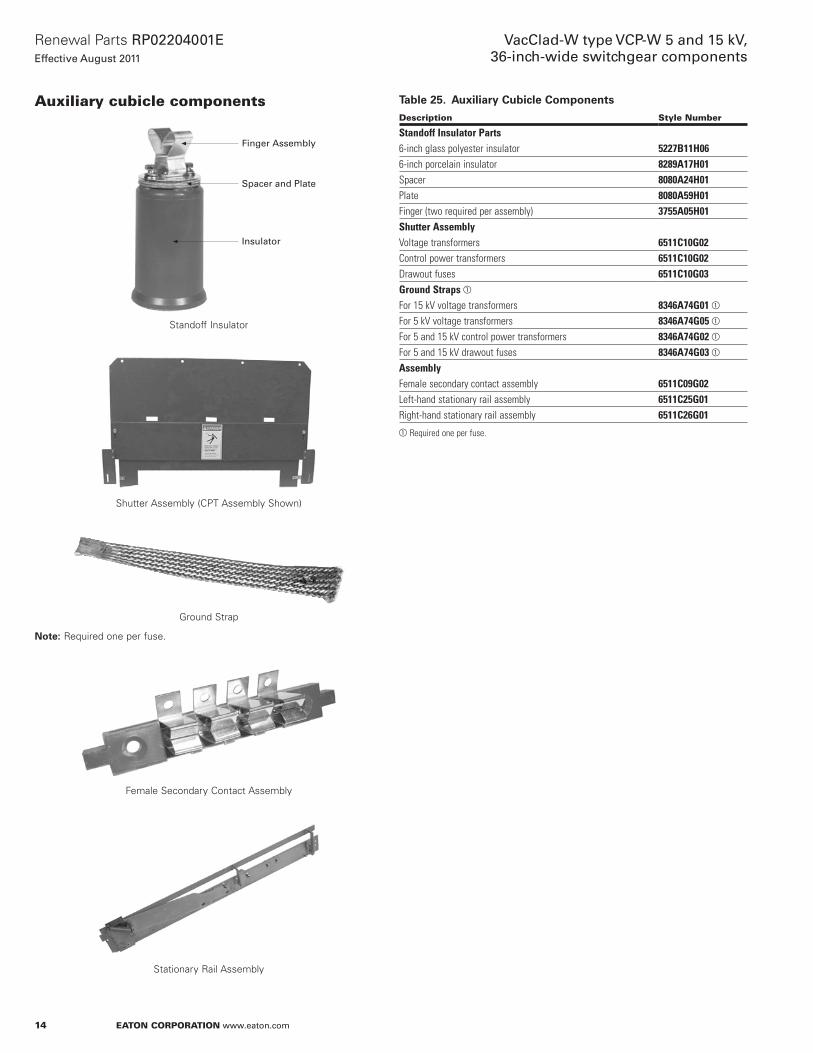
Auxiliary cubicle components
Finger Assembly
Spacer and Plate
Insulator
Standoff Insulator
Shutter Assembly (CPT Assembly Shown)
Ground Strap
otee:N Required one per fuse .
Female Secondary Contact Assembly
Stationary Rail Assembly
Table 25. Auxiliary Cubicle Components
Description Style Number
Standoff Insulator Parts6-inch glass polyester insulator 5227B11H066-inch porcelain insulator 8289A17H01Spacer 8080A24H01Plate 8080A59H01Finger (two required per assembly) 3755A05H01Shutter AssemblyVoltage transformers 6511C10G02Control power transformers 6511C10G02Drawout fuses 6511C10G03Ground Straps a
For 15 kV voltage transformers 8346A74G01 a
For 5 kV voltage transformers 8346A74G05 a
For 5 and 15 kV control power transformers 8346A74G02 a
For 5 and 15 kV drawout fuses 8346A74G03 a
AssemblyFemale secondary contact assembly 6511C09G02Left-hand stationary rail assembly 6511C25G01Right-hand stationary rail assembly 6511C26G01aRequired one per fuse.
15
Renewal Parts RP02204001EEffective August 2011
VacClad-W type VCP-W 5 and 15 kV, 36-inch-wide switchgear components
EATON CORPORATION www.eaton.com
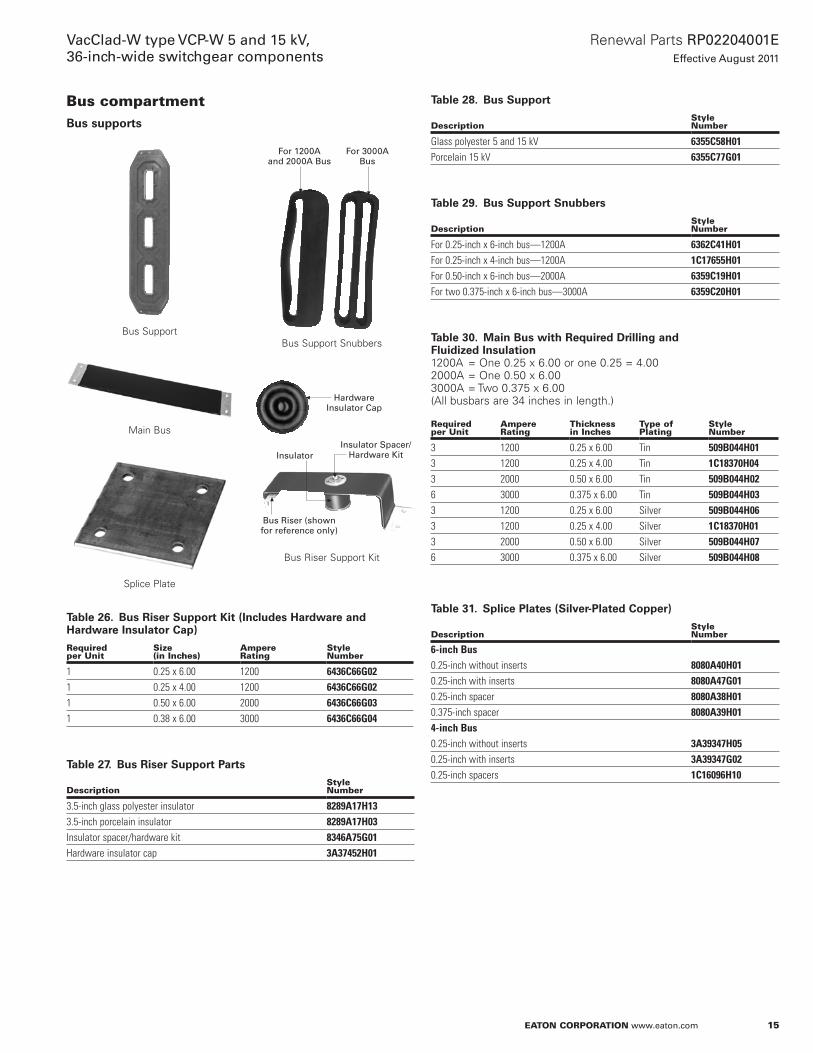
Bus compartmentBus supports
Bus Support
Main Bus
Splice Plate
For 1200A and 2000A Bus
For 3000A Bus
Bus Support Snubbers
Hardware Insulator Cap
Insulator Spacer/Hardware Kit
Bus Riser (shown for reference only)
Insulator
Bus Riser Support Kit
Table 26. Bus Riser Support Kit (Includes Hardware and Hardware Insulator Cap)
Required per Unit
Size (in Inches)
Ampere Rating
Style Number
1 0.25 x 6.00 1200 6436C66G021 0.25 x 4.00 1200 6436C66G021 0.50 x 6.00 2000 6436C66G031 0.38 x 6.00 3000 6436C66G04
Table 27. Bus Riser Support Parts
DescriptionStyle Number
3.5-inch glass polyester insulator 8289A17H133.5-inch porcelain insulator 8289A17H03Insulator spacer/hardware kit 8346A75G01Hardware insulator cap 3A37452H01
Table 28. Bus Support
DescriptionStyle Number
Glass polyester 5 and 15 kV 6355C58H01Porcelain 15 kV 6355C77G01
Table 29. Bus Support Snubbers
DescriptionStyle Number
For 0.25-inch x 6-inch bus—1200A 6362C41H01For 0.25-inch x 4-inch bus—1200A 1C17655H01For 0.50-inch x 6-inch bus—2000A 6359C19H01For two 0.375-inch x 6-inch bus—3000A 6359C20H01
Table 30. Main Bus with Required Drilling and Fluidized Insulation1200A = One 0 .25 x 6 .00 or one 0 .25 = 4 .00 2000A = One 0 .50 x 6 .00 3000A = Two 0 .375 x 6 .00 (All busbars are 34 inches in length .)
Required per Unit
Ampere Rating
Thickness in Inches
Type of Plating
Style Number
3 1200 0.25 x 6.00 Tin 509B044H013 1200 0.25 x 4.00 Tin 1C18370H043 2000 0.50 x 6.00 Tin 509B044H026 3000 0.375 x 6.00 Tin 509B044H033 1200 0.25 x 6.00 Silver 509B044H063 1200 0.25 x 4.00 Silver 1C18370H013 2000 0.50 x 6.00 Silver 509B044H076 3000 0.375 x 6.00 Silver 509B044H08
Table 31. Splice Plates (Silver-Plated Copper)
DescriptionStyle Number
6-inch Bus0.25-inch without inserts 8080A40H010.25-inch with inserts 8080A47G010.25-inch spacer 8080A38H010.375-inch spacer 8080A39H014-inch Bus0.25-inch without inserts 3A39347H050.25-inch with inserts 3A39347G020.25-inch spacers 1C16096H10
16
Renewal Parts RP02204001EEffective August 2011
VacClad-W type VCP-W 5 and 15 kV, 36-inch-wide switchgear components
EATON CORPORATION www.eaton.com
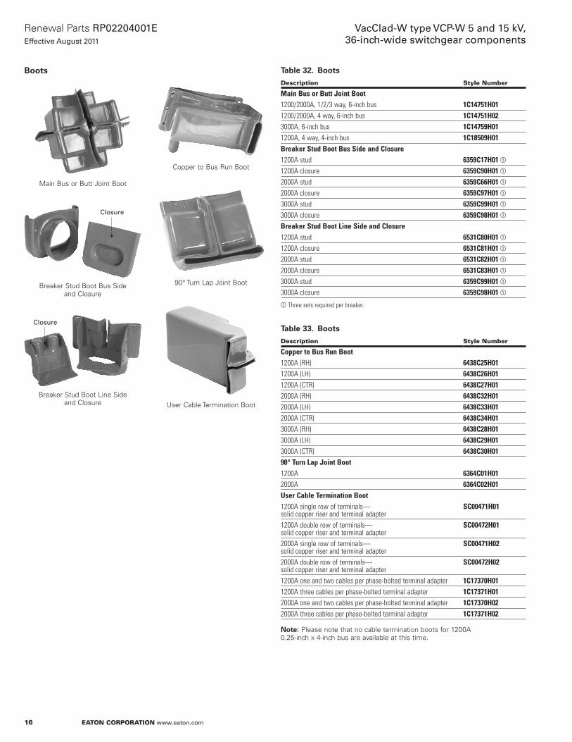
Boots
Main Bus or Butt Joint Boot
Breaker Stud Boot Bus Side and Closure
Breaker Stud Boot Line Side and Closure
Copper to Bus Run Boot
90° Turn Lap Joint Boot
User Cable Termination Boot
Table 32. Boots
Description Style Number
Main Bus or Butt Joint Boot1200/2000A, 1/2/3 way, 6-inch bus 1C14751H011200/2000A, 4 way, 6-inch bus 1C14751H023000A, 6-inch bus 1C14759H011200A, 4 way, 4-inch bus 1C18509H01Breaker Stud Boot Bus Side and Closure1200A stud 6359C17H01 a
1200A closure 6359C90H01 a
2000A stud 6359C66H01 a
2000A closure 6359C97H01 a
3000A stud 6359C99H01 a
3000A closure 6359C98H01 a
Breaker Stud Boot Line Side and Closure1200A stud 6531C80H01 a
1200A closure 6531C81H01 a
2000A stud 6531C82H01 a
2000A closure 6531C83H01 a
3000A stud 6359C99H01 a
3000A closure 6359C98H01 a
aThree sets required per breaker.
Table 33. Boots
Description Style Number
Copper to Bus Run Boot1200A (RH) 6438C25H011200A (LH) 6438C26H011200A (CTR) 6438C27H012000A (RH) 6438C32H012000A (LH) 6438C33H012000A (CTR) 6438C34H013000A (RH) 6438C28H013000A (LH) 6438C29H013000A (CTR) 6438C30H0190° Turn Lap Joint Boot1200A 6364C01H012000A 6364C02H01User Cable Termination Boot1200A single row of terminals— solid copper riser and terminal adapter
SC00471H01
1200A double row of terminals— solid copper riser and terminal adapter
SC00472H01
2000A single row of terminals— solid copper riser and terminal adapter
SC00471H02
2000A double row of terminals— solid copper riser and terminal adapter
SC00472H02
1200A one and two cables per phase-bolted terminal adapter 1C17370H011200A three cables per phase-bolted terminal adapter 1C17371H012000A one and two cables per phase-bolted terminal adapter 1C17370H022000A three cables per phase-bolted terminal adapter 1C17371H02
otee:N Please note that no cable termination boots for 1200A 0 .25-inch x 4-inch bus are available at this time .
Closure
Closure

17
Renewal Parts RP02204001EEffective August 2011
VacClad-W type VCP-W 5 and 15 kV, 36-inch-wide switchgear components
EATON CORPORATION www.eaton.com
Accessories and miscellaneous parts
Maintenance Tool
Portable Lifting Crane
Levering Crank with Clutch
Breaker Lifting Yoke
Rail Extensions
Rail Clamps
Breaker Ramp Assembly
Dockable Dolly
Table 34. Accessories and Miscellaneous Parts
Description Style Number
VCP-W maintenance tool 8064A02G01Arc resistant maintenance tool 3A71173G01Standard levering crank with clutch 701B601G01Through door levering crank with clutch 701B601G13Breaker lifting yoke 691C607G01Portable lifting crane 1C19086H01Right-hand rail extension 7813C41G01Left-hand rail extension 7813C41G02Rail clamps 6511C83G01Breaker ramp assembly 1C14163G12Indoor dockable dolly 6510C71G01Outdoor aisleless dockable dolly 6510C71G03Arc resistant (longer) breaker ramp assembly 1C18881G01
18
Renewal Parts RP02204001EEffective August 2011
VacClad-W type VCP-W 5 and 15 kV, 36-inch-wide switchgear components
EATON CORPORATION www.eaton.com
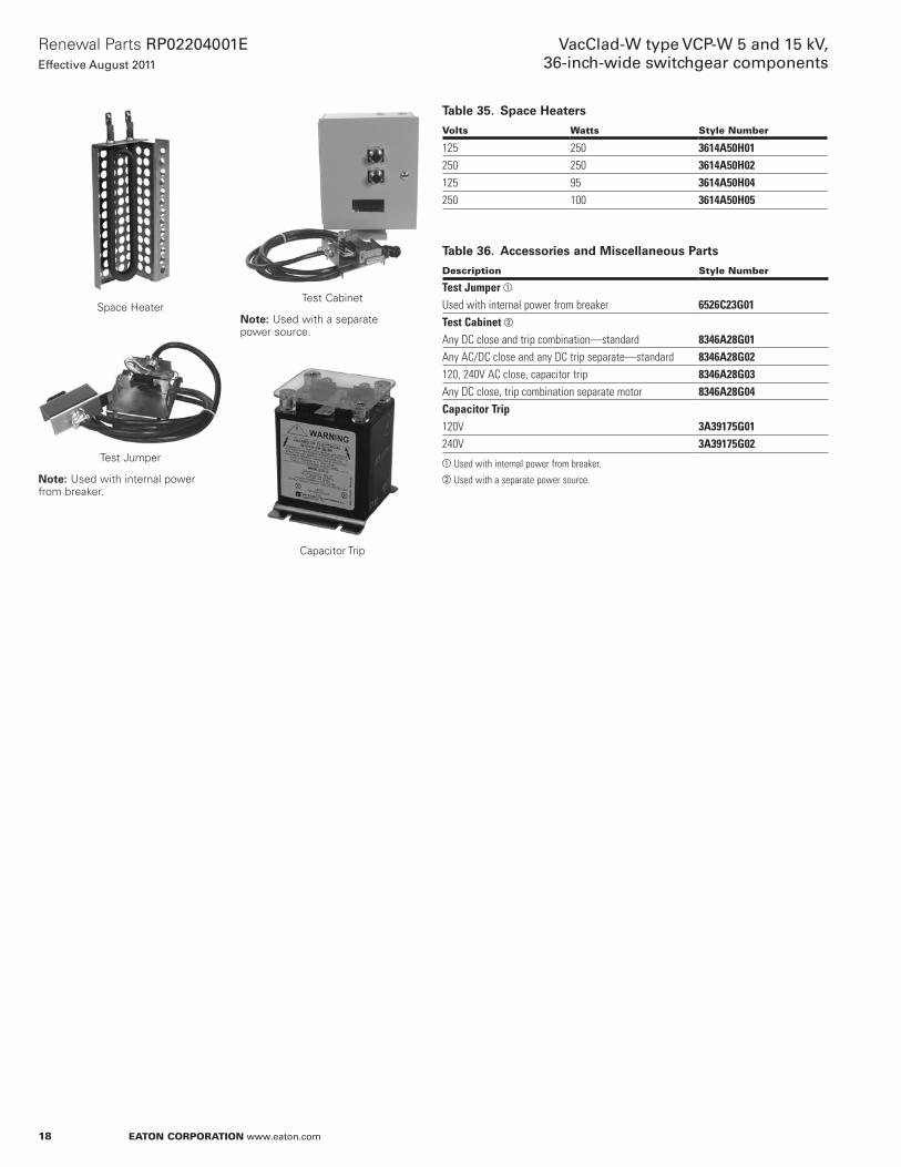
Space Heater
Test Jumper
otee:N Used with internal power from breaker .
Test Cabinet
otee:N Used with a separate power source .
Capacitor Trip
Table 35. Space Heaters
Volts Watts Style Number
125 250 3614A50H01250 250 3614A50H02125 95 3614A50H04250 100 3614A50H05
Table 36. Accessories and Miscellaneous Parts
Description Style Number
Test Jumper a
Used with internal power from breaker 6526C23G01Test Cabinet b
Any DC close and trip combination—standard 8346A28G01Any AC/DC close and any DC trip separate—standard 8346A28G02120, 240V AC close, capacitor trip 8346A28G03Any DC close, trip combination separate motor 8346A28G04Capacitor Trip120V 3A39175G01240V 3A39175G02aUsed with internal power from breaker.bUsed with a separate power source.
19
Renewal Parts RP02204001EEffective August 2011
VacClad-W type VCP-W 5 and 15 kV, 36-inch-wide switchgear components
EATON CORPORATION www.eaton.com
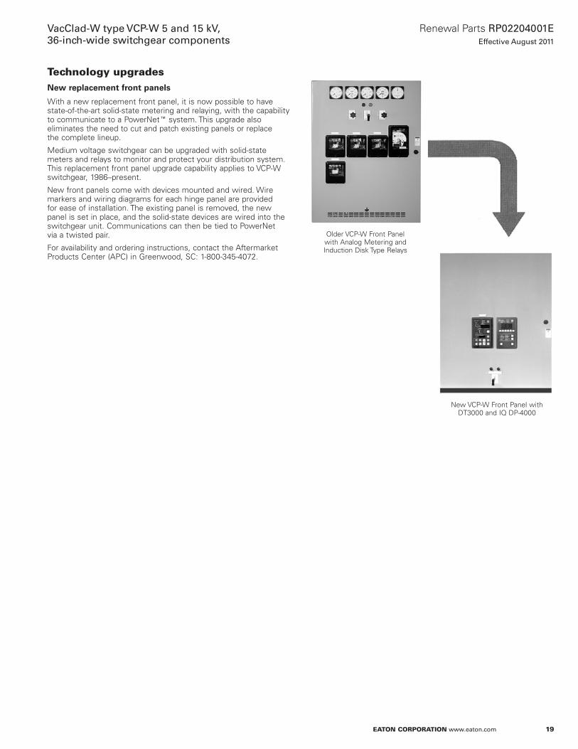
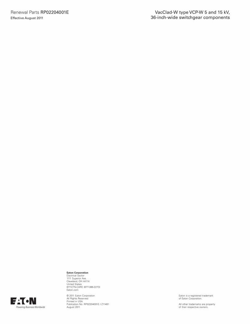
Technology upgradesNew replacement front panels
With a new replacement front panel, it is now possible to have state-of-the-art solid-state metering and relaying, with the capability to communicate to a PowerNetE system . This upgrade also eliminates the need to cut and patch existing panels or replace the complete lineup .
Medium voltage switchgear can be upgraded with solid-state meters and relays to monitor and protect your distribution system . This replacement front panel upgrade capability applies to VCP-W switchgear, 1986–present .
New front panels come with devices mounted and wired . Wire markers and wiring diagrams for each hinge panel are provided for ease of installation . The existing panel is removed, the new panel is set in place, and the solid-state devices are wired into the switchgear unit . Communications can then be tied to PowerNet via a twisted pair .
For availability and ordering instructions, contact the Aftermarket Products Center (APC) in Greenwood, SC: 1-800-345-4072 .
Older VCP-W Front Panel with Analog Metering and Induction Disk Type Relays
New VCP-W Front Panel with DT3000 and IQ DP-4000
Eaton CorporationElectrical Sector1111 Superior Ave .Cleveland, OH 44114United States877-ETN-CARE (877-386-2273)Eaton .com
© 2011 Eaton CorporationAll Rights ReservedPrinted in USAPublication No . RP02204001E / Z11481August 2011
Eaton is a registered trademark of Eaton Corporation .
All other trademarks are property of their respective owners .
Renewal Parts RP02204001EEffective August 2011
VacClad-W type VCP-W 5 and 15 kV, 36-inch-wide switchgear components
Related Documents