Journal of Engineering journal homepage: www.joe.uobaghdad.edu.iq Number 10 Volume 25 October 2019 *Corresponding author Peer review under the responsibility of University of Baghdad. https://doi.org/10.31026/j.eng.2019.10.7 2520-3339 © 2019 University of Baghdad. Production and hosting by Journal of Engineering. This is an open access article under the CC BY-NC license http://creativecommons.org/licenses/by-nc/4.0/). Article received: 22/11/2018 Article accepted: 24/12/2018 88 Civil and Architectural Engineering Effect of Use Recycled Coarse Aggregate on the Behavior of Axially Loaded Reinforced Concrete Columns Dr. Omar Shamal Farhan Lecturer, Civil Engineering Department, Al-Nahrain University Baghdad, Iraq [email protected] ABSTRACT Nowadays, the use of recycled waste construction materials instead of aggregates is becoming popular in construction owing to its environmental benefits. This paper presents an experimental and analytical campaign to study the behavior of axially loaded columns constructed from recycled aggregates. The latter was used instead of natural aggregates, and they were collected from the waste of previous concrete constructions. Different concrete mixtures made from varying amounts of recycled aggregates ranged from 0 to 50% of the total coarse aggregate were conducted to achieve 28 MPa. The effect of steel fibers is another investigated variable with volumes ranged from 0 to 2% concerning concrete’s mixture. The experimental results showed that the concrete strength is dependent on the amount of recycled aggregates. When the recycled aggregates were less than 30% of the total aggregates, they had a negligible effect on concrete strength and the load carrying capacity of the column models were improved. Also, the presence of steel fibers enhanced the load carrying capacity of the columns constructed from concrete with recycled aggregates of more than 30%. Finite element analysis (using ANSYS 16.1 software program) was conducted to simulate the experimental investigations, and they achieved good agreements with the test results. Keywords: ANSYS, column, recycled aggregates, steel fiber, waste materials. تأثير استخدام تدويره على تصرفلمعادم الخشن الركا اسلحة محوريةنية الملخرساعمدة ا اتحميل ال عمر شمال فرحان مدرس هندسةهرينمعة الن مدني/ جاصة الخلبنا في اً شائعاً أمرالركام من اً تدويرها بدلمعادء البنا مواد ا الراهن، أصبح استخدام في الوقتبسب ء ب فوائده ال بيئية. تم دراسة ال سلوك ليتحليي والعمل ال عمدة خرسانية محوريةتحميل الستبدال بالركامسب من ا ن بركام تدويره. معادم استخ حيث ت د ام نسبتراوح من ت0 إلى50 م الخشنلركالي ان إجما م٪ )الحصى( رهانة مقدا مقاومة خرسايق لتحق28 لم نت/م2 . إن تلياف أثير اتراوح مننسب تغير آخر تم فحصه بذية هو مت الفو0 إلى2 . أ٪ لخرسان أن قوة ابية التجريلنتائج ظهرت اتمد على كمية ة تعطة أقل منخل الويره داخل تدلمعادم الركانت نسبة اره. حيث عندما كا تدويلمعادم الركا ا30 نسبة من٪ اعي، فانم الطبي لركا تأثيرحمل ال تحسين قدرة تحمللخرسانة وتم على قوة انسبة ضئيلذه ال هقصى ا لنماذجعمدة ا. ك ذلك فإجود ا ن ولياف زذية قد عز الفو ال قدرة علىدة ال زيا حملعمدةقصى ل ا التيحتوي على نسبة ت تدويره معاد ركام كثر من30 ٪ . تم برنامج استخدامدةصر المحدلعنايل ا تحل( ANSYS ) ة ال لمحاكا وذلك جزءعملي ال وحققتفقات توا جيدة مع الئج ال نتا عملية.

Welcome message from author
This document is posted to help you gain knowledge. Please leave a comment to let me know what you think about it! Share it to your friends and learn new things together.
Transcript
Journal of Engineering
journal homepage: www.joe.uobaghdad.edu.iq
Number 10 Volume 25 October 2019
*Corresponding author
Peer review under the responsibility of University of Baghdad.
https://doi.org/10.31026/j.eng.2019.10.7
2520-3339 © 2019 University of Baghdad. Production and hosting by Journal of Engineering.
This is an open access article under the CC BY-NC license http://creativecommons.org/licenses/by-nc/4.0/).
Article received: 22/11/2018
Article accepted: 24/12/2018
88
Civil and Architectural Engineering
Effect of Use Recycled Coarse Aggregate on the Behavior of Axially Loaded
Reinforced Concrete Columns
Dr. Omar Shamal Farhan
Lecturer, Civil Engineering Department, Al-Nahrain University
Baghdad, Iraq
ABSTRACT
Nowadays, the use of recycled waste construction materials instead of aggregates is becoming
popular in construction owing to its environmental benefits. This paper presents an experimental
and analytical campaign to study the behavior of axially loaded columns constructed from
recycled aggregates. The latter was used instead of natural aggregates, and they were collected
from the waste of previous concrete constructions. Different concrete mixtures made from
varying amounts of recycled aggregates ranged from 0 to 50% of the total coarse aggregate were
conducted to achieve 28 MPa. The effect of steel fibers is another investigated variable with
volumes ranged from 0 to 2% concerning concrete’s mixture. The experimental results showed
that the concrete strength is dependent on the amount of recycled aggregates. When the recycled
aggregates were less than 30% of the total aggregates, they had a negligible effect on concrete
strength and the load carrying capacity of the column models were improved. Also, the presence
of steel fibers enhanced the load carrying capacity of the columns constructed from concrete
with recycled aggregates of more than 30%. Finite element analysis (using ANSYS 16.1
software program) was conducted to simulate the experimental investigations, and they achieved
good agreements with the test results.
Keywords: ANSYS, column, recycled aggregates, steel fiber, waste materials.
التحميل الأعمدة الخرسانية المسلحة محورية الركام الخشن المعاد تدويره على تصرفاستخدام تأثير
عمر شمال فرحان
مدرس
مدني/ جامعة النهرينهندسة
الخلاصة
بيئية. تم دراسة فوائده ال ء بسببفي الوقت الراهن، أصبح استخدام مواد البناء المعاد تدويرها بدلاً من الركام أمراً شائعاً في البنا
ام نسبدحيث تم استخ معاد تدويره.بركام نسب من الركام باستبدال التحميل محورية خرسانية عمدةالعملي والتحليلي لأسلوك ال
أثير الألياف ت إن. 2نت/ملم 28لتحقيق مقاومة خرسانة مقدارها )الحصى( ٪ من إجمالي الركام الخشن50إلى 0تتراوح من
ة تعتمد على كمية ظهرت النتائج التجريبية أن قوة الخرسان٪. أ2إلى 0الفولاذية هو متغير آخر تم فحصه بنسب تتراوح من
لركام الطبيعي، فان ا٪ من نسبة 30الركام المعاد تدويره. حيث عندما كانت نسبة الركام المعاد تدويره داخل الخلطة أقل من
لألياف ن وجود اذلك فإك. الأعمدةلنماذج الأقصىهذه النسبة ضئيل على قوة الخرسانة وتم تحسين قدرة تحمل الحمل تأثير
تم .٪30كثر من ركام معاد تدويره لأتحتوي على نسبة التي الأقصى للأعمدة حملزيادة القدرة على الالفولاذية قد عزز
.عمليةنتائج الالجيدة مع توافقاتوحققت العملي جزءوذلك لمحاكاة ال( ANSYS) تحليل العناصر المحددةاستخدام برنامج
Journal of Engineering Volume 25 October 2019 Number 10
89
.ANSYSعمود، مواد النفايات، الركام المعاد تدويره، الألياف الفولاذية، برنامج الرئيسية:الكلمات
1. INTRODUCTION
In Iraq, the significant presence of concrete blocks, and the large number probably to be utilized
and re-used in concrete mixes instead, of course, aggregate (gravel) where the study of the
subject of alternative gravel in reinforced concrete mixes from the practical and economic
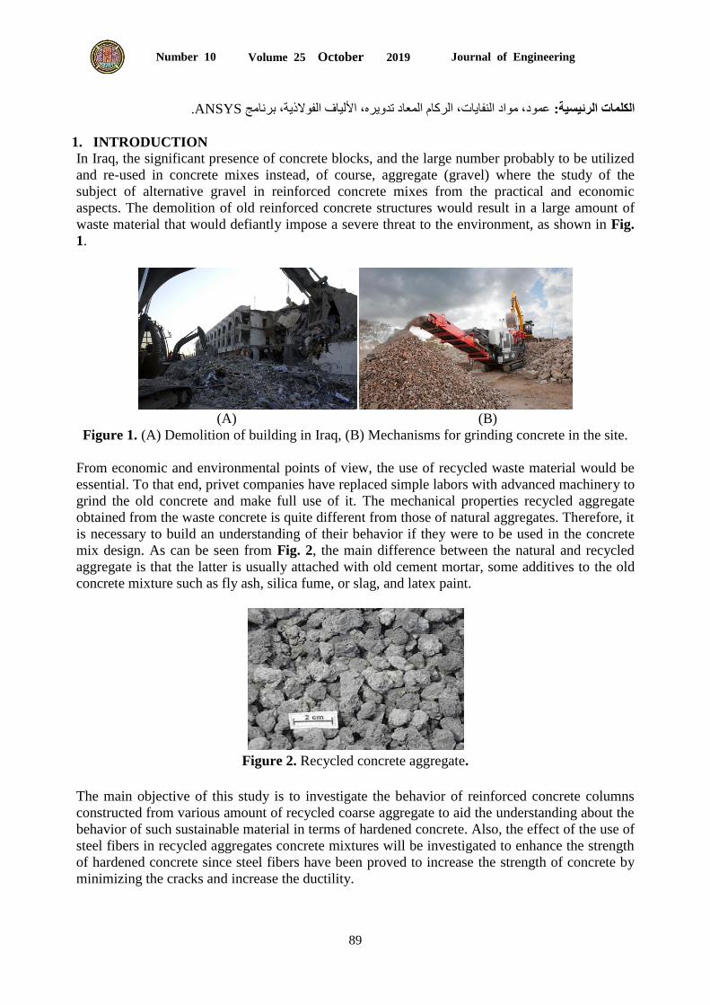
aspects. The demolition of old reinforced concrete structures would result in a large amount of
waste material that would defiantly impose a severe threat to the environment, as shown in Fig.
1.
(A) (B)
Figure 1. (A) Demolition of building in Iraq, (B) Mechanisms for grinding concrete in the site.
From economic and environmental points of view, the use of recycled waste material would be
essential. To that end, privet companies have replaced simple labors with advanced machinery to
grind the old concrete and make full use of it. The mechanical properties recycled aggregate
obtained from the waste concrete is quite different from those of natural aggregates. Therefore, it
is necessary to build an understanding of their behavior if they were to be used in the concrete
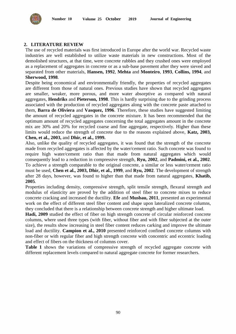
mix design. As can be seen from Fig. 2, the main difference between the natural and recycled
aggregate is that the latter is usually attached with old cement mortar, some additives to the old
concrete mixture such as fly ash, silica fume, or slag, and latex paint.
Figure 2. Recycled concrete aggregate.
The main objective of this study is to investigate the behavior of reinforced concrete columns
constructed from various amount of recycled coarse aggregate to aid the understanding about the
behavior of such sustainable material in terms of hardened concrete. Also, the effect of the use of
steel fibers in recycled aggregates concrete mixtures will be investigated to enhance the strength
of hardened concrete since steel fibers have been proved to increase the strength of concrete by
minimizing the cracks and increase the ductility.
Journal of Engineering Volume 25 October 2019 Number 10
90
2. LITERATURE REVIEW
The use of recycled materials was first introduced in Europe after the world war. Recycled waste
industries are well established to utilize waste materials in new constructions. Most of the
demolished structures, at that time, were concrete rubbles and they crushed ones were employed
as a replacement of aggregates in concrete or as a sub-base pavement after they were sieved and
separated from other materials, Hansen, 1992, Mehta and Monteiro, 1993, Collins, 1994, and
Sherwood, 1998.
Despite being economical and environmentally friendly, the properties of recycled aggregates
are different from those of natural ones. Previous studies have shown that recycled aggregates
are smaller, weaker, more porous, and more water absorptive as compared with natural
aggregates, Hendriks and Pieterson, 1998. This is hardly surprising due to the grinding process
associated with the production of recycled aggregates along with the concrete paste attached to
them, Barra de Oliviera and Vasquez, 1996. Therefore, these studies have suggested limiting
the amount of recycled aggregates in the concrete mixture. It has been recommended that the
optimum amount of recycled aggregates concerning the total aggregates amount in the concrete
mix are 30% and 20% for recycled coarse and fine aggregate, respectively. Higher than these
limits would reduce the strength of concrete due to the reasons explained above, Katz, 2003,
Chen, et al., 2003, and Dhir, et al., 1999.
Also, unlike the quality of recycled aggregates, it was found that the strength of the concrete
made from recycled aggregates is affected by the water/cement ratio. Such concrete was found to
require high water/cement ratio than that made from natural aggregates which would
consequently lead to a reduction in compressive strength, Ryu, 2002, and Padmini, et al., 2002.
To achieve a strength comparable to the original concrete, a similar or less water/cement ratio
must be used, Chen et al., 2003, Dhir, et al., 1999, and Ryu, 2002. The development of strength
after 28 days, however, was found to higher than that made from natural aggregates, Khatib,
2005.
Properties including density, compressive strength, split tensile strength, flexural strength and
modulus of elasticity are proved by the addition of steel fiber to concrete mixes to reduce
concrete cracking and increased the ductility. Efe and Musbau, 2011, presented an experimental
work on the effect of different steel fiber content and shape upon lateralized concrete columns,
they concluded that there is a relationship between concrete strength and higher ultimate load.
Hadi, 2009 studied the effect of fiber on high strength concrete of circular reinforced concrete
columns, where used three types (with fiber, without fiber and with fiber subjected at the outer
size), the results show increasing in steel fiber content reduces carking and improve the ultimate
load and ductility. Campion et al., 2010 presented reinforced confined concrete columns with
non-fiber or with regular fiber and high strength concrete with concentric and eccentric loading
and effect of fibers on the thickness of columns cover.
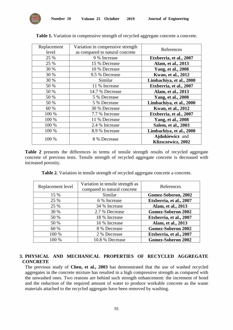
Table 1 shows the variations of compressive strength of recycled aggregate concrete with
different replacement levels compared to natural aggregate concrete for former researchers.
Journal of Engineering Volume 25 October 2019 Number 10
91
Table 1. Variation in compressive strength of recycled aggregate concrete a concrete.
Replacement
level
Variation in compressive strength
as compared to natural concrete References
25 % 9 % Increase Etxberria, et al., 2007
25 % 15 % Decrease Alam, et al., 2013
30 % 10 % Decrease Yang, et al., 2008
30 % 9.5 % Decrease Kwan, et al., 2012
30 % Similar Limbachiya, et al., 2000
50 % 11 % Increase Etxberria, et al., 2007
50 % 14.7 % Decrease Alam, et al., 2013
50 % 5 % Decrease Yang, et al., 2008
50 % 5 % Decrease Limbachiya, et al., 2000
60 % 30 % Decrease Kwan, et al., 2012
100 % 7.7 % Increase Etxberria, et al., 2007
100 % 11 % Decrease Yang, et al., 2008
100 % 2.4 % Increase Salem, et al., 2003
100 % 8.9 % Increase Limbachiya, et al., 2000
100 % 8 % Decrease Ajdukiewicz and
Klizsczewicz, 2002
Table 2 presents the differences in terms of tensile strength results of recycled aggregate
concrete of previous tests. Tensile strength of recycled aggregate concrete is decreased with
increased porosity.
Table 2. Variation in tensile strength of recycled aggregate concrete a concrete.
Replacement level Variation in tensile strength as
compared to natural concrete References
15 % Similar Gomez-Soberon, 2002
25 % 6 % Increase Etxberria, et al., 2007
25 % 34 % Increase Alam, et al., 2013
30 % 2.7 % Decrease Gomez-Soberon 2002
50 % 18 % Increase Etxberria, et al., 2007
50 % 16 % Increase Alam, et al., 2013
60 % 8 % Decrease Gomez-Soberon 2002
100 % 2 % Decrease Etxberria, et al., 2007
100 % 10.8 % Decrease Gomez-Soberon 2002
3. PHYSICAL AND MECHANICAL PROPERTIES OF RECYCLED AGGREGATE
CONCRETE
The previous study of Chen, et al., 2003 has demonstrated that the use of washed recycled
aggregates in the concrete mixture has resulted in a high compressive strength as compared with
the unwashed ones. Two reasons are behind such strength enhancement: the increment of bond
and the reduction of the required amount of water to produce workable concrete as the waste
materials attached to the recycled aggregate have been removed by washing.
Journal of Engineering Volume 25 October 2019 Number 10
92
The use of recycled aggregate from local landfills would contribute to a reduction in high
transportation costs currently incurred through the use of natural aggregate. Abbas, et al., 2009
found the physical properties of recycled aggregate concrete are affected by the residual mortar
quantity and characteristics, this method can directly account for any deficiencies low-quality
aggregate, balancing the mix without affecting the mechanical and durability-related
performance of the final concrete. This allows the recycled aggregate concrete mix to be
prepared with a similar internal structure to that of natural aggregate concrete.
Akbari, et al., 2011 studied the effect of recycled aggregate concrete on the mechanical
properties of fresh and hardened concrete. Akbari’s study has shown that concrete made from
100% recycled aggregates exhibited a 12.2% and 8.2% increase in concrete strength and
permeability as compared to that made from natural aggregates. And, a 17.7% reduction in
modulus of elasticity, as compared to that made from natural aggregates. Umoh, 2012 found
Reductions in terms of compressive and flexural strengths, and workability of concrete when
recycled aggregates were used as compared to those of concrete made from natural aggregates.
4. WATER ABSORPTION
One of the most important problems of recycled aggregate is the absorption of water, where all
the previous researches showed a higher water absorption rate than regular concrete (that
contained normal aggregate). This is because the original cement mortar in recycled aggregate
has a porosity higher than the natural gravel, this will affect the concrete density whereby its
porosity primarily depends on the W/C ratio of the original (old) concrete. Thus, the absorption
of water of recycled aggregate is even greater, as the quantity of mortar, which is attached grains
of the original recycled aggregate increases. It has been shown in practice that the stated amount of cement mortar in recycled aggregate
ranges from 25% to 65% (in volume percentage) and that it differs in certain fractions – the
smaller the portion, the higher the amount of cement mortar, as well as the level of water
absorption, Marinkovic, 2009. Also, the analyses undertaken in extensive research around the
world indicate that the stated amount of old cement mortar depends on the crushing method in
the recycling process, thereby, according to some researchers, the maximum amount of mortar
layer in recycled aggregate is recommended to less than 44% for constructional concrete.
Additionally, the researchers from the University of Hong Kong recommend that the amount of
recycled aggregate in structural concrete should range from 20% to 30%, to ensure that the
maximum water absorption of aggregate used is less than 5%, Jevtic, et al., 2009.
5. EXPERIMENTAL PROGRAM
The experimental program consists of casting and testing eight identical short column specimens
of the (100*100*700 mm) with different recycled aggregate replacement levels of (0, 10, 20, 30,
40 and 50%). Also, a percentage of steel fiber was added to the specimens in which the
compression strength was reduced when the replacement of coarse aggregate, the percentage of
steel fiber which used (0, 1 and 2%) to the concrete mix to investigate the difference in the
behavior of these specimens when subjected to axial loading. The experimental program consists
of control column was casting and testing with natural aggregate without recycled aggregate to
comparison with other columns that contained recycled aggregate. All columns specimens have a
top and bottom bearing rubber of 2 mm thick plate to prevent end bearing failure of the two ends
and to ensure that the load is distributed uniformly overall the column ends. All specimens were
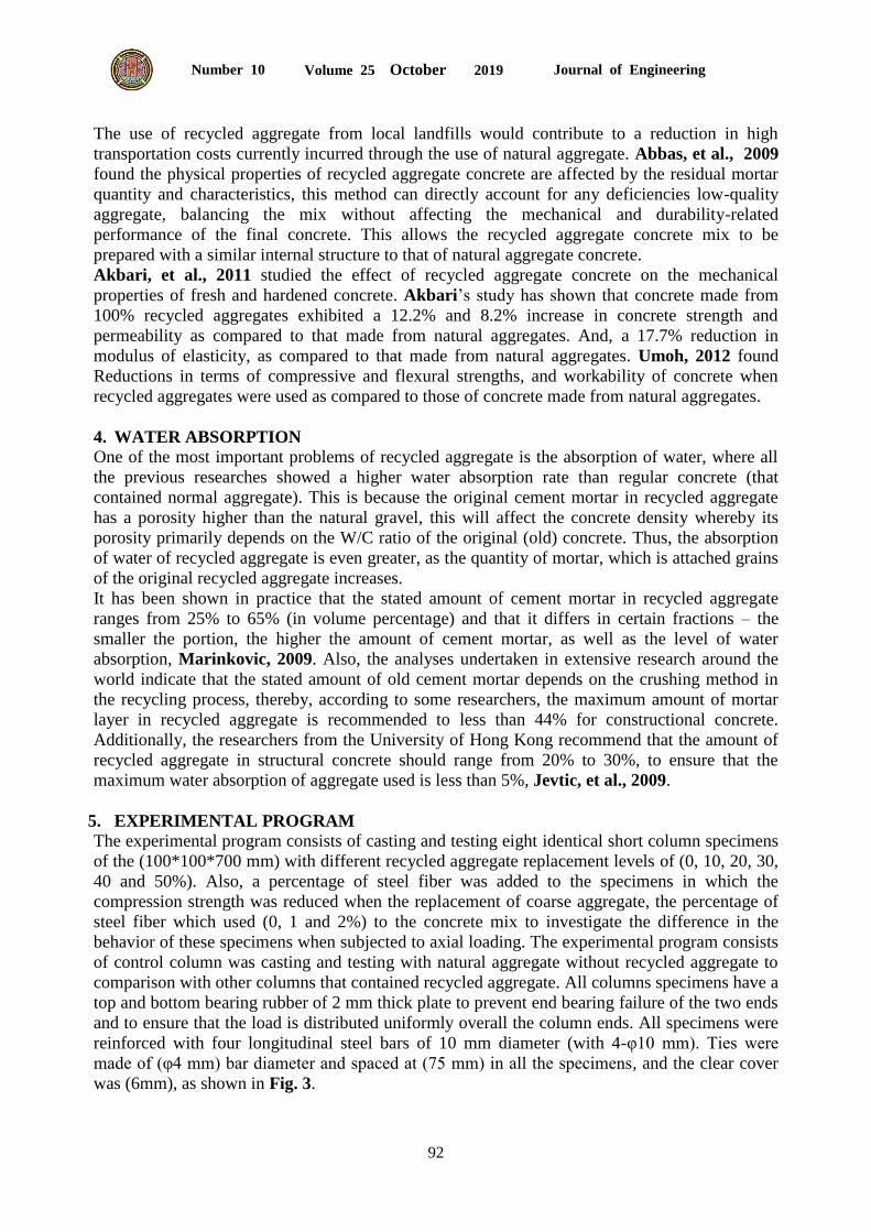
reinforced with four longitudinal steel bars of 10 mm diameter (with 4-φ10 mm). Ties were
made of (φ4 mm) bar diameter and spaced at (75 mm) in all the specimens, and the clear cover
was (6mm), as shown in Fig. 3.
Journal of Engineering Volume 25 October 2019 Number 10
93
Figure 3. Details dimensions and reinforcement of the tested column.
6. DESCRIPTION OF MATERIALS AND PROPERTIES
6.1 Cement
All specimens reported in the study were constructed using Ordinary Portland cement type I
from a local manufacturer and conform to the Iraqi specification No.5/1984.
6.2 Fine Aggregate
The fine aggregates used to construct the specimens were tested to determine their mechanical
and chemical properties and conform to the Iraqi Specification No.45/1984 (zone 2).
6.3 Natural Coarse Aggregate
The coarse aggregates used to construct the specimens are crushed to natural ones with a
maximum size of 10 mm. The grading of this type of aggregate was conforming according to the
Iraqi specification No.45/1984.
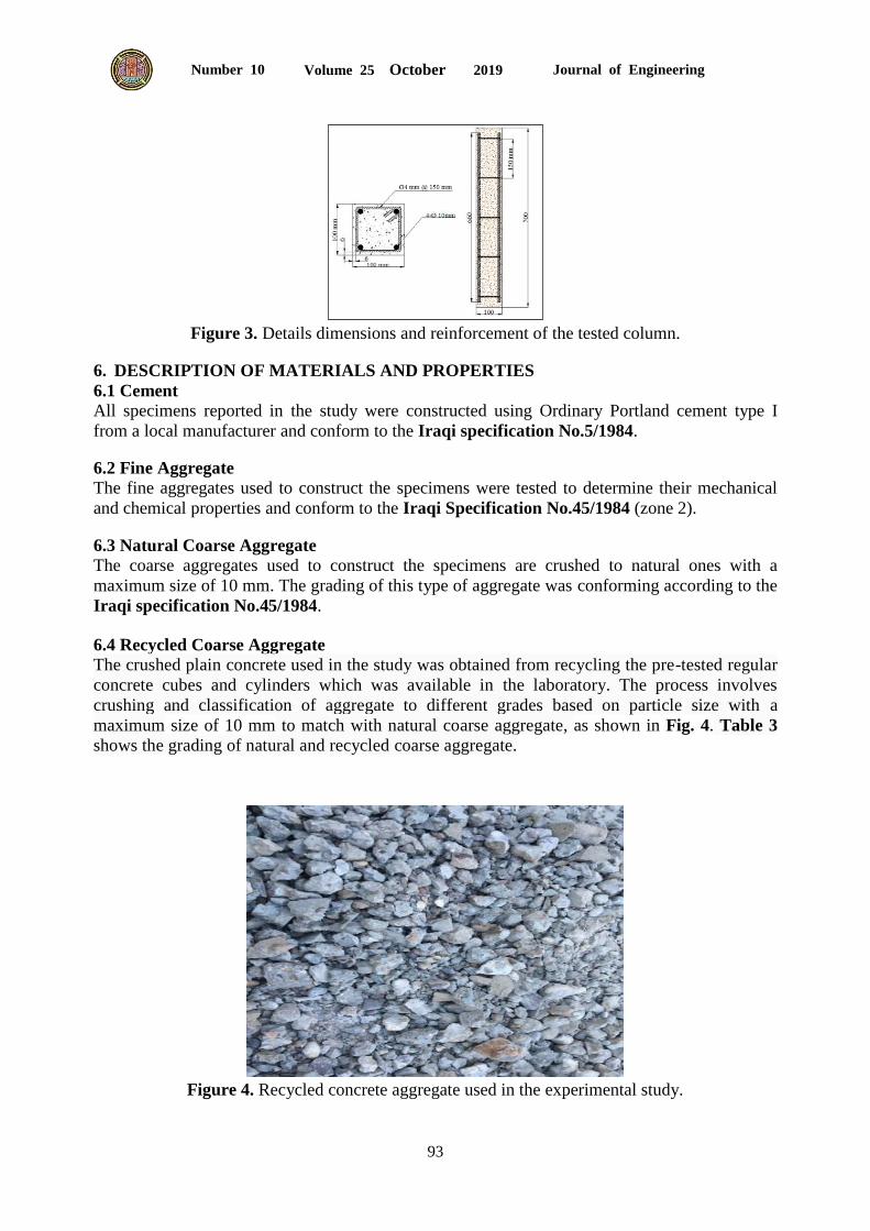
6.4 Recycled Coarse Aggregate
The crushed plain concrete used in the study was obtained from recycling the pre-tested regular
concrete cubes and cylinders which was available in the laboratory. The process involves
crushing and classification of aggregate to different grades based on particle size with a
maximum size of 10 mm to match with natural coarse aggregate, as shown in Fig. 4. Table 3
shows the grading of natural and recycled coarse aggregate.
Figure 4. Recycled concrete aggregate used in the experimental study.
Journal of Engineering Volume 25 October 2019 Number 10
94
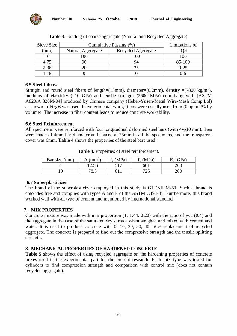
Table 3. Grading of coarse aggregate (Natural and Recycled Aggregate).
Sieve Size
(mm)
Cumulative Passing (%) Limitations of
IQS Natural Aggregate Recycled Aggregate
10 100 100 100
4.75 90 94 85-100
2.36 20 25 0-25
1.18 0 0 0-5
6.5 Steel Fibers Straight and round steel fibers of length=(13mm), diameter=(0.2mm), density =(7800 kg/m3),
modulus of elasticity=(210 GPa) and tensile strength=(2600 MPa) complying with [ASTM
A820/A 820M-04] produced by Chinese company (Hebei-Yusen-Metal Wire-Mesh Comp.Ltd)
as shown in Fig. 6 was used. In experimental work, fibers were usually used from (0 up to 2% by
volume). The increase in fiber content leads to reduce concrete workability.
6.6 Steel Reinforcement
All specimens were reinforced with four longitudinal deformed steel bars (with 4-φ10 mm). Ties
were made of 4mm bar diameter and spaced at 75mm in all the specimens, and the transparent
cover was 6mm. Table 4 shows the properties of the steel bars used.
Table 4. Properties of steel reinforcement.
Bar size (mm) A (mm2) fy (MPa) fu (MPa) Es (GPa)
4 12.56 517 601 200
10 78.5 611 725 200
6.7 Superplasticizer
The brand of the superplasticizer employed in this study is GLENIUM-51. Such a brand is
chlorides free and complies with types A and F of the ASTM C494-05. Furthermore, this brand
worked well with all type of cement and mentioned by international standard.
7. MIX PROPERTIES
Concrete mixture was made with mix proportion (1: 1.44: 2.22) with the ratio of w/c (0.4) and
the aggregate in the case of the saturated dry surface when weighed and mixed with cement and
water. It is used to produce concrete with 0, 10, 20, 30, 40, 50% replacement of recycled
aggregate. The concrete is prepared to find out the compressive strength and the tensile splitting
strength.
8. MECHANICAL PROPERTIES OF HARDENED CONCRETE
Table 5 shows the effect of using recycled aggregate on the hardening properties of concrete
mixes used in the experimental part for the present research. Each mix type was tested for
cylinders to find compression strength and comparison with control mix (does not contain
recycled aggregate).
Journal of Engineering Volume 25 October 2019 Number 10
95
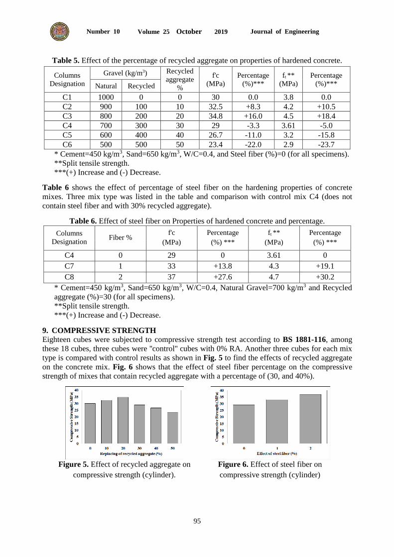
Table 5. Effect of the percentage of recycled aggregate on properties of hardened concrete.
Columns
Designation
Gravel (kg/m3) Recycled
aggregate
%
f'c
(MPa)
Percentage
(%)***
ft **
(MPa)
Percentage
(%)*** Natural Recycled
C1 1000 0 0 30 0.0 3.8 0.0
C2 900 100 10 32.5 +8.3 4.2 +10.5
C3 800 200 20 34.8 +16.0 4.5 +18.4
C4 700 300 30 29 -3.3 3.61 -5.0
C5 600 400 40 26.7 -11.0 3.2 -15.8
C6 500 500 50 23.4 -22.0 2.9 -23.7
* Cement=450 kg/m3, Sand=650 kg/m3, W/C=0.4, and Steel fiber (%)=0 (for all specimens).
**Split tensile strength.
***(+) Increase and (-) Decrease.
Table 6 shows the effect of percentage of steel fiber on the hardening properties of concrete
mixes. Three mix type was listed in the table and comparison with control mix C4 (does not
contain steel fiber and with 30% recycled aggregate).
Table 6. Effect of steel fiber on Properties of hardened concrete and percentage.
Columns
Designation Fiber %
f'c
(MPa)
Percentage
(%) ***
ft **
(MPa)
Percentage
(%) ***
C4 0 29 0 3.61 0
C7 1 33 +13.8 4.3 +19.1
C8 2 37 +27.6 4.7 +30.2
* Cement=450 kg/m3, Sand=650 kg/m3, W/C=0.4, Natural Gravel=700 kg/m3 and Recycled
aggregate (%)=30 (for all specimens).
**Split tensile strength.
***(+) Increase and (-) Decrease.
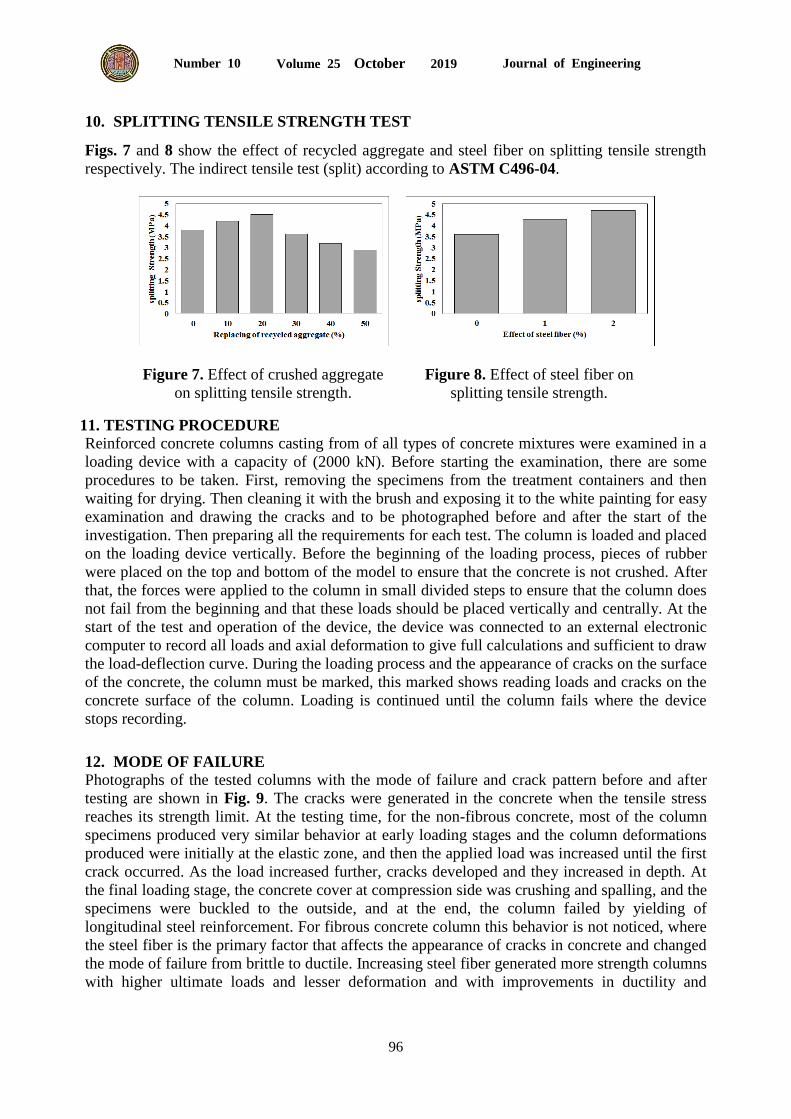
9. COMPRESSIVE STRENGTH
Eighteen cubes were subjected to compressive strength test according to BS 1881-116, among
these 18 cubes, three cubes were ''control'' cubes with 0% RA. Another three cubes for each mix
type is compared with control results as shown in Fig. 5 to find the effects of recycled aggregate
on the concrete mix. Fig. 6 shows that the effect of steel fiber percentage on the compressive
strength of mixes that contain recycled aggregate with a percentage of (30, and 40%).
Figure 5. Effect of recycled aggregate on
compressive strength (cylinder).
Figure 6. Effect of steel fiber on
compressive strength (cylinder)
Journal of Engineering Volume 25 October 2019 Number 10
96
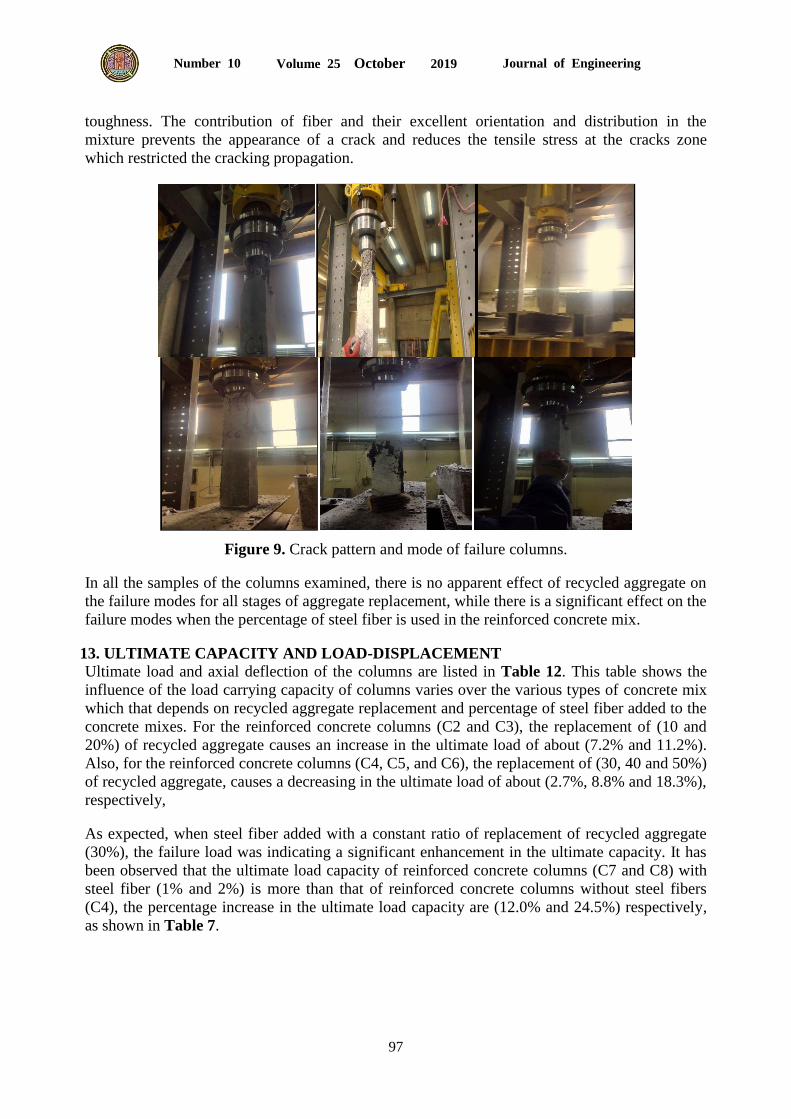
10. SPLITTING TENSILE STRENGTH TEST
Figs. 7 and 8 show the effect of recycled aggregate and steel fiber on splitting tensile strength
respectively. The indirect tensile test (split) according to ASTM C496-04.
Figure 7. Effect of crushed aggregate
on splitting tensile strength.
Figure 8. Effect of steel fiber on
splitting tensile strength.
11. TESTING PROCEDURE
Reinforced concrete columns casting from of all types of concrete mixtures were examined in a
loading device with a capacity of (2000 kN). Before starting the examination, there are some
procedures to be taken. First, removing the specimens from the treatment containers and then
waiting for drying. Then cleaning it with the brush and exposing it to the white painting for easy
examination and drawing the cracks and to be photographed before and after the start of the
investigation. Then preparing all the requirements for each test. The column is loaded and placed
on the loading device vertically. Before the beginning of the loading process, pieces of rubber
were placed on the top and bottom of the model to ensure that the concrete is not crushed. After
that, the forces were applied to the column in small divided steps to ensure that the column does
not fail from the beginning and that these loads should be placed vertically and centrally. At the
start of the test and operation of the device, the device was connected to an external electronic
computer to record all loads and axial deformation to give full calculations and sufficient to draw
the load-deflection curve. During the loading process and the appearance of cracks on the surface
of the concrete, the column must be marked, this marked shows reading loads and cracks on the
concrete surface of the column. Loading is continued until the column fails where the device
stops recording.
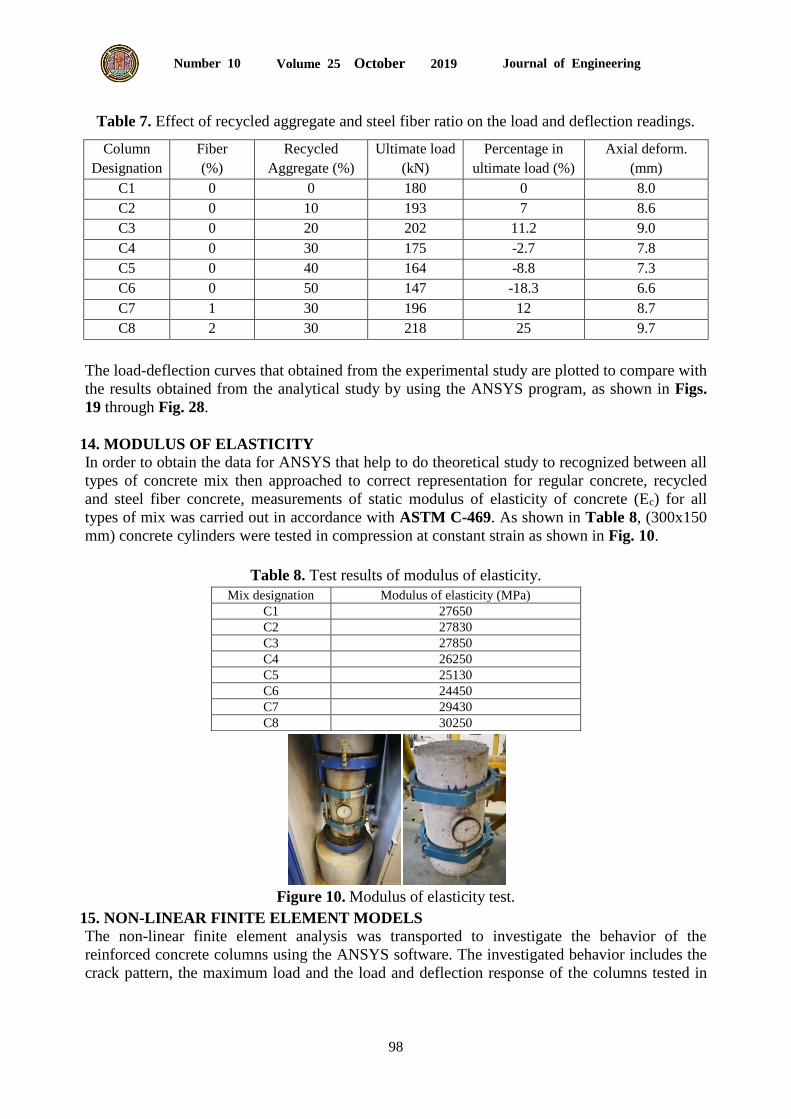
12. MODE OF FAILURE
Photographs of the tested columns with the mode of failure and crack pattern before and after
testing are shown in Fig. 9. The cracks were generated in the concrete when the tensile stress
reaches its strength limit. At the testing time, for the non-fibrous concrete, most of the column
specimens produced very similar behavior at early loading stages and the column deformations
produced were initially at the elastic zone, and then the applied load was increased until the first
crack occurred. As the load increased further, cracks developed and they increased in depth. At
the final loading stage, the concrete cover at compression side was crushing and spalling, and the
specimens were buckled to the outside, and at the end, the column failed by yielding of
longitudinal steel reinforcement. For fibrous concrete column this behavior is not noticed, where
the steel fiber is the primary factor that affects the appearance of cracks in concrete and changed
the mode of failure from brittle to ductile. Increasing steel fiber generated more strength columns
with higher ultimate loads and lesser deformation and with improvements in ductility and
Journal of Engineering Volume 25 October 2019 Number 10
97
toughness. The contribution of fiber and their excellent orientation and distribution in the
mixture prevents the appearance of a crack and reduces the tensile stress at the cracks zone
which restricted the cracking propagation.
Figure 9. Crack pattern and mode of failure columns.
In all the samples of the columns examined, there is no apparent effect of recycled aggregate on
the failure modes for all stages of aggregate replacement, while there is a significant effect on the
failure modes when the percentage of steel fiber is used in the reinforced concrete mix.
13. ULTIMATE CAPACITY AND LOAD-DISPLACEMENT
Ultimate load and axial deflection of the columns are listed in Table 12. This table shows the influence of the load carrying capacity of columns varies over the various types of concrete mix
which that depends on recycled aggregate replacement and percentage of steel fiber added to the
concrete mixes. For the reinforced concrete columns (C2 and C3), the replacement of (10 and
20%) of recycled aggregate causes an increase in the ultimate load of about (7.2% and 11.2%).
Also, for the reinforced concrete columns (C4, C5, and C6), the replacement of (30, 40 and 50%)
of recycled aggregate, causes a decreasing in the ultimate load of about (2.7%, 8.8% and 18.3%),
respectively,
As expected, when steel fiber added with a constant ratio of replacement of recycled aggregate
(30%), the failure load was indicating a significant enhancement in the ultimate capacity. It has
been observed that the ultimate load capacity of reinforced concrete columns (C7 and C8) with
steel fiber (1% and 2%) is more than that of reinforced concrete columns without steel fibers
(C4), the percentage increase in the ultimate load capacity are (12.0% and 24.5%) respectively,
as shown in Table 7.
Journal of Engineering Volume 25 October 2019 Number 10
98
Table 7. Effect of recycled aggregate and steel fiber ratio on the load and deflection readings.
Column
Designation
Fiber
(%)
Recycled
Aggregate (%)
Ultimate load
(kN)
Percentage in
ultimate load (%)
Axial deform.
(mm)
C1 0 0 180 0 8.0
C2 0 10 193 7 8.6
C3 0 20 202 11.2 9.0
C4 0 30 175 -2.7 7.8
C5 0 40 164 -8.8 7.3
C6 0 50 147 -18.3 6.6
C7 1 30 196 12 8.7
C8 2 30 218 25 9.7
The load-deflection curves that obtained from the experimental study are plotted to compare with
the results obtained from the analytical study by using the ANSYS program, as shown in Figs.
19 through Fig. 28.
14. MODULUS OF ELASTICITY
In order to obtain the data for ANSYS that help to do theoretical study to recognized between all
types of concrete mix then approached to correct representation for regular concrete, recycled
and steel fiber concrete, measurements of static modulus of elasticity of concrete (Ec) for all
types of mix was carried out in accordance with ASTM C-469. As shown in Table 8, (300x150
mm) concrete cylinders were tested in compression at constant strain as shown in Fig. 10.
Table 8. Test results of modulus of elasticity.
Mix designation Modulus of elasticity (MPa)
C1 27650
C2 27830
C3 27850
C4 26250
C5 25130
C6 24450
C7 29430
C8 30250
Figure 10. Modulus of elasticity test.
15. NON-LINEAR FINITE ELEMENT MODELS
The non-linear finite element analysis was transported to investigate the behavior of the
reinforced concrete columns using the ANSYS software. The investigated behavior includes the
crack pattern, the maximum load and the load and deflection response of the columns tested in
Journal of Engineering Volume 25 October 2019 Number 10
99
the laboratory. An acceptable concordance was found between the experimental tests
conclusions and the finite element program.
16. GEOMETRY MODELING
In this study, eight columns were analyzed by ANSYS (Released 16.1) programs to make
verification study with the dimensions and properties corresponding to the actual experimental
data. The specimen will be modeled using eight-node three-dimensional concrete solid element
(SOLID65) and (link8) element was used to model the steel reinforcement, with two nodes to
represents the link element, with 3 degrees of freedom and translations in x, y, and z directions.
The comparison shows that the ANSYS nonlinear finite element program is capable of modeling
and predicting the actual nonlinear behavior of columns with having different characteristics.
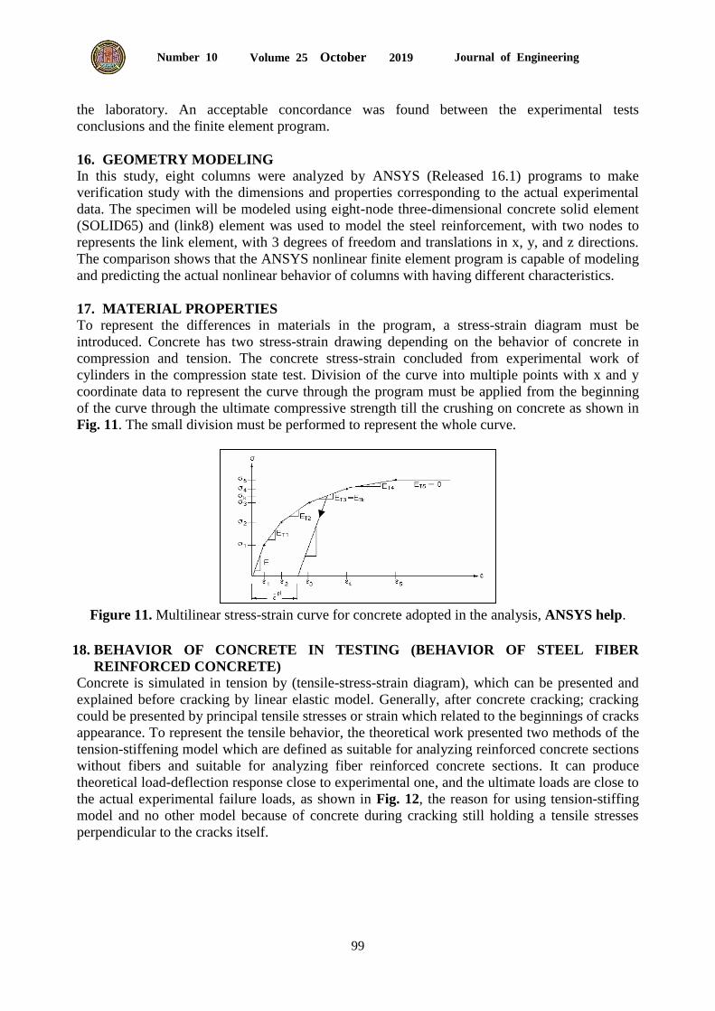
17. MATERIAL PROPERTIES
To represent the differences in materials in the program, a stress-strain diagram must be
introduced. Concrete has two stress-strain drawing depending on the behavior of concrete in
compression and tension. The concrete stress-strain concluded from experimental work of
cylinders in the compression state test. Division of the curve into multiple points with x and y
coordinate data to represent the curve through the program must be applied from the beginning
of the curve through the ultimate compressive strength till the crushing on concrete as shown in
Fig. 11. The small division must be performed to represent the whole curve.
Figure 11. Multilinear stress-strain curve for concrete adopted in the analysis, ANSYS help.
18. BEHAVIOR OF CONCRETE IN TESTING (BEHAVIOR OF STEEL FIBER
REINFORCED CONCRETE)
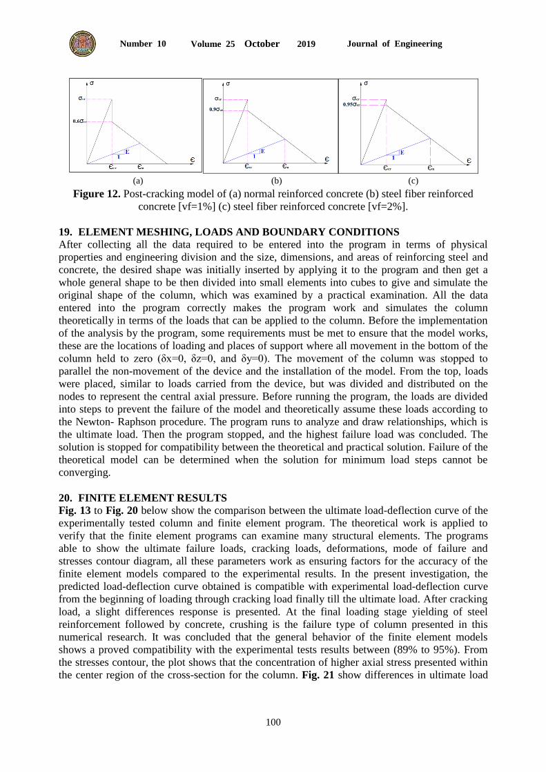
Concrete is simulated in tension by (tensile-stress-strain diagram), which can be presented and
explained before cracking by linear elastic model. Generally, after concrete cracking; cracking
could be presented by principal tensile stresses or strain which related to the beginnings of cracks
appearance. To represent the tensile behavior, the theoretical work presented two methods of the
tension-stiffening model which are defined as suitable for analyzing reinforced concrete sections
without fibers and suitable for analyzing fiber reinforced concrete sections. It can produce
theoretical load-deflection response close to experimental one, and the ultimate loads are close to
the actual experimental failure loads, as shown in Fig. 12, the reason for using tension-stiffing
model and no other model because of concrete during cracking still holding a tensile stresses
perpendicular to the cracks itself.
Journal of Engineering Volume 25 October 2019 Number 10
100
(a) (b) (c)
Figure 12. Post-cracking model of (a) normal reinforced concrete (b) steel fiber reinforced
concrete [vf=1%] (c) steel fiber reinforced concrete [vf=2%].
19. ELEMENT MESHING, LOADS AND BOUNDARY CONDITIONS
After collecting all the data required to be entered into the program in terms of physical
properties and engineering division and the size, dimensions, and areas of reinforcing steel and
concrete, the desired shape was initially inserted by applying it to the program and then get a
whole general shape to be then divided into small elements into cubes to give and simulate the
original shape of the column, which was examined by a practical examination. All the data
entered into the program correctly makes the program work and simulates the column
theoretically in terms of the loads that can be applied to the column. Before the implementation
of the analysis by the program, some requirements must be met to ensure that the model works,
these are the locations of loading and places of support where all movement in the bottom of the
column held to zero (δx=0, δz=0, and δy=0). The movement of the column was stopped to
parallel the non-movement of the device and the installation of the model. From the top, loads
were placed, similar to loads carried from the device, but was divided and distributed on the
nodes to represent the central axial pressure. Before running the program, the loads are divided
into steps to prevent the failure of the model and theoretically assume these loads according to
the Newton- Raphson procedure. The program runs to analyze and draw relationships, which is
the ultimate load. Then the program stopped, and the highest failure load was concluded. The
solution is stopped for compatibility between the theoretical and practical solution. Failure of the
theoretical model can be determined when the solution for minimum load steps cannot be
converging.
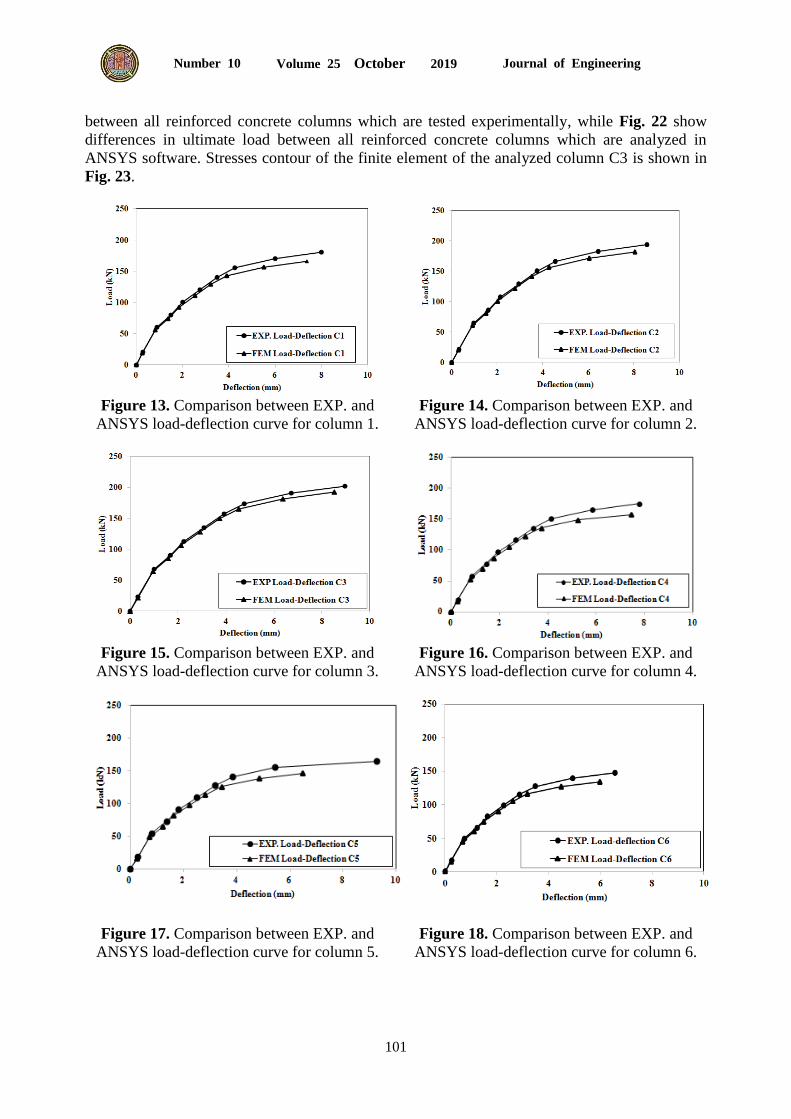
20. FINITE ELEMENT RESULTS
Fig. 13 to Fig. 20 below show the comparison between the ultimate load-deflection curve of the
experimentally tested column and finite element program. The theoretical work is applied to
verify that the finite element programs can examine many structural elements. The programs
able to show the ultimate failure loads, cracking loads, deformations, mode of failure and
stresses contour diagram, all these parameters work as ensuring factors for the accuracy of the
finite element models compared to the experimental results. In the present investigation, the
predicted load-deflection curve obtained is compatible with experimental load-deflection curve
from the beginning of loading through cracking load finally till the ultimate load. After cracking
load, a slight differences response is presented. At the final loading stage yielding of steel
reinforcement followed by concrete, crushing is the failure type of column presented in this
numerical research. It was concluded that the general behavior of the finite element models
shows a proved compatibility with the experimental tests results between (89% to 95%). From
the stresses contour, the plot shows that the concentration of higher axial stress presented within
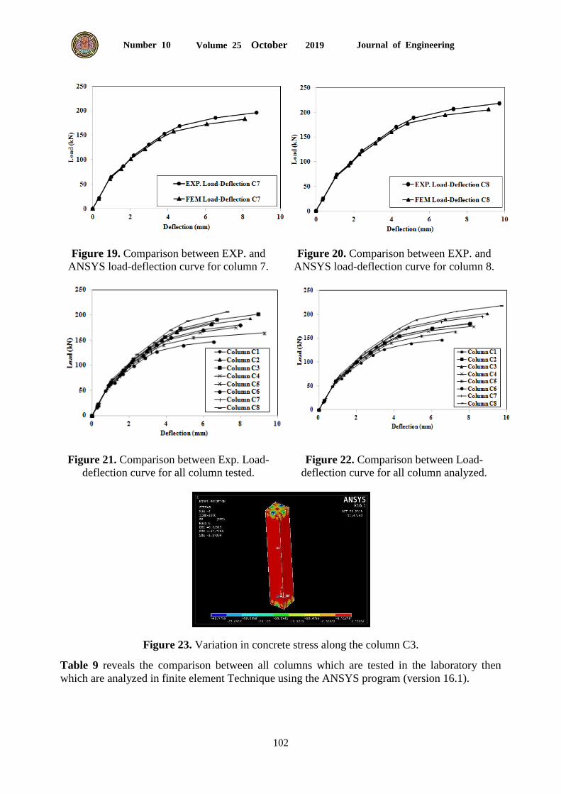
the center region of the cross-section for the column. Fig. 21 show differences in ultimate load
Journal of Engineering Volume 25 October 2019 Number 10
101
between all reinforced concrete columns which are tested experimentally, while Fig. 22 show
differences in ultimate load between all reinforced concrete columns which are analyzed in
ANSYS software. Stresses contour of the finite element of the analyzed column C3 is shown in
Fig. 23.
Figure 13. Comparison between EXP. and
ANSYS load-deflection curve for column 1.
Figure 14. Comparison between EXP. and
ANSYS load-deflection curve for column 2.
Figure 15. Comparison between EXP. and
ANSYS load-deflection curve for column 3.
Figure 16. Comparison between EXP. and
ANSYS load-deflection curve for column 4.
Figure 17. Comparison between EXP. and
ANSYS load-deflection curve for column 5.
Figure 18. Comparison between EXP. and
ANSYS load-deflection curve for column 6.
Journal of Engineering Volume 25 October 2019 Number 10
102
Figure 19. Comparison between EXP. and
ANSYS load-deflection curve for column 7.
Figure 20. Comparison between EXP. and
ANSYS load-deflection curve for column 8.
Figure 21. Comparison between Exp. Load-
deflection curve for all column tested.
Figure 22. Comparison between Load-
deflection curve for all column analyzed.
Figure 23. Variation in concrete stress along the column C3.
Table 9 reveals the comparison between all columns which are tested in the laboratory then
which are analyzed in finite element Technique using the ANSYS program (version 16.1).
Journal of Engineering Volume 25 October 2019 Number 10
103
Table 9. Comparison between experimental ultimate load and ANSYS.
Column designation Ultimate load (kN) FEM. load (kN) FEM/EXP
C1 180 166 0.92
C2 193 181 0.94
C3 202 192 0.95
C4 175 158 0.90
C5 164 146 0.89
C6 147 134 0.91
C7 196 182 0.93
C8 218 205 0.94
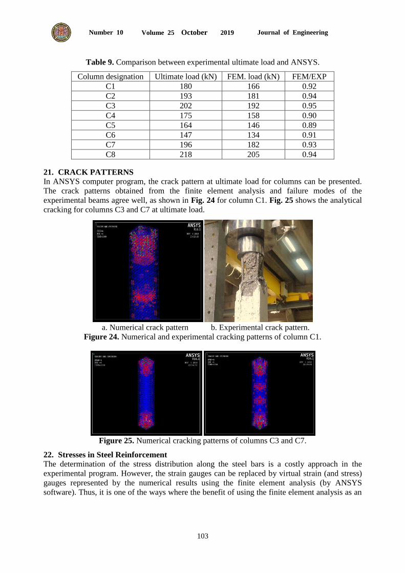
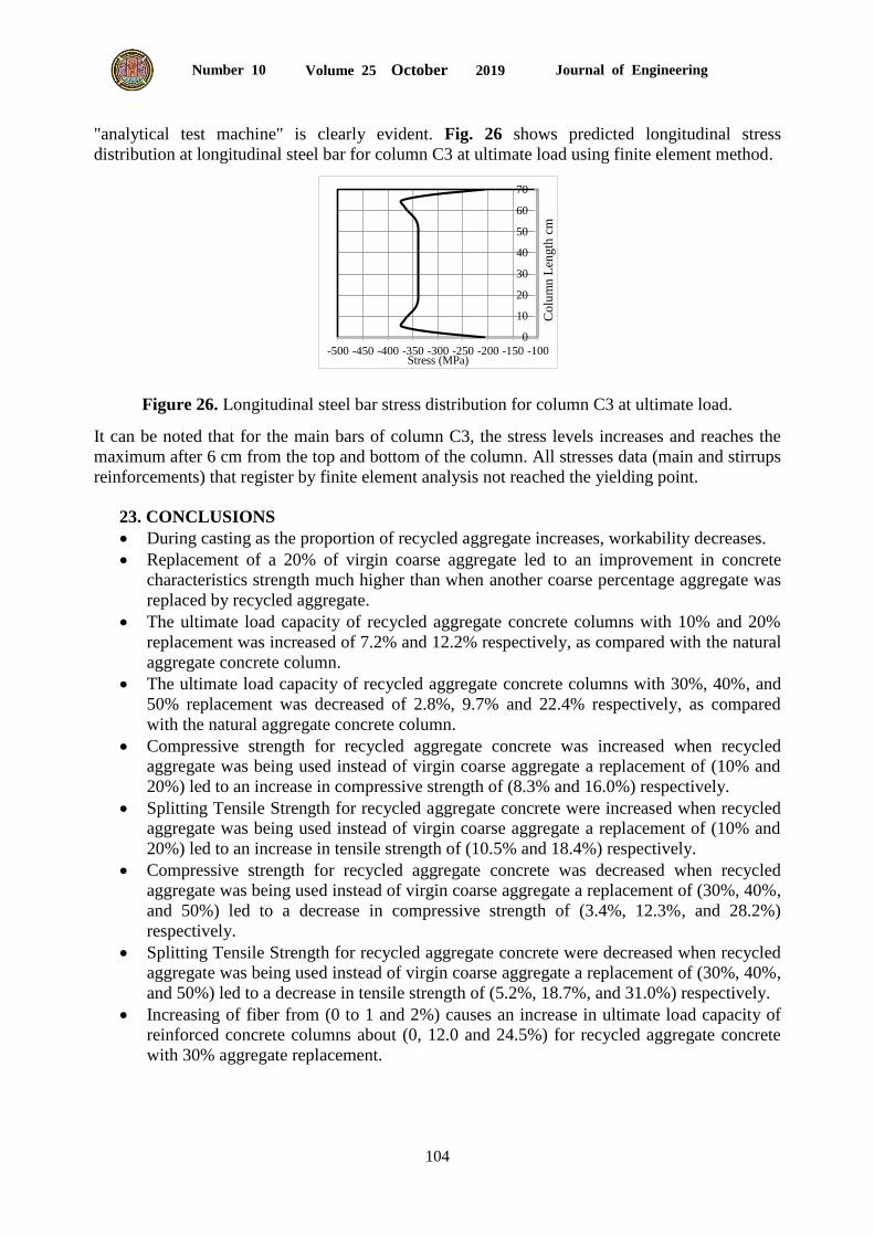
21. CRACK PATTERNS
In ANSYS computer program, the crack pattern at ultimate load for columns can be presented.
The crack patterns obtained from the finite element analysis and failure modes of the
experimental beams agree well, as shown in Fig. 24 for column C1. Fig. 25 shows the analytical
cracking for columns C3 and C7 at ultimate load.
a. Numerical crack pattern b. Experimental crack pattern.
Figure 24. Numerical and experimental cracking patterns of column C1.
Figure 25. Numerical cracking patterns of columns C3 and C7.
22. Stresses in Steel Reinforcement
The determination of the stress distribution along the steel bars is a costly approach in the
experimental program. However, the strain gauges can be replaced by virtual strain (and stress)
gauges represented by the numerical results using the finite element analysis (by ANSYS
software). Thus, it is one of the ways where the benefit of using the finite element analysis as an
Journal of Engineering Volume 25 October 2019 Number 10
104
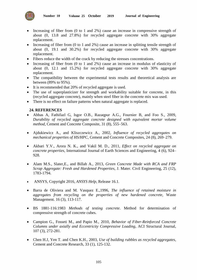
"analytical test machine" is clearly evident. Fig. 26 shows predicted longitudinal stress
distribution at longitudinal steel bar for column C3 at ultimate load using finite element method.
Figure 26. Longitudinal steel bar stress distribution for column C3 at ultimate load.
It can be noted that for the main bars of column C3, the stress levels increases and reaches the
maximum after 6 cm from the top and bottom of the column. All stresses data (main and stirrups
reinforcements) that register by finite element analysis not reached the yielding point.
23. CONCLUSIONS
During casting as the proportion of recycled aggregate increases, workability decreases.
Replacement of a 20% of virgin coarse aggregate led to an improvement in concrete
characteristics strength much higher than when another coarse percentage aggregate was
replaced by recycled aggregate.
The ultimate load capacity of recycled aggregate concrete columns with 10% and 20%
replacement was increased of 7.2% and 12.2% respectively, as compared with the natural
aggregate concrete column.
The ultimate load capacity of recycled aggregate concrete columns with 30%, 40%, and
50% replacement was decreased of 2.8%, 9.7% and 22.4% respectively, as compared
with the natural aggregate concrete column.
Compressive strength for recycled aggregate concrete was increased when recycled
aggregate was being used instead of virgin coarse aggregate a replacement of (10% and
20%) led to an increase in compressive strength of (8.3% and 16.0%) respectively.
Splitting Tensile Strength for recycled aggregate concrete were increased when recycled
aggregate was being used instead of virgin coarse aggregate a replacement of (10% and
20%) led to an increase in tensile strength of (10.5% and 18.4%) respectively.
Compressive strength for recycled aggregate concrete was decreased when recycled
aggregate was being used instead of virgin coarse aggregate a replacement of (30%, 40%,
and 50%) led to a decrease in compressive strength of (3.4%, 12.3%, and 28.2%)
respectively.
Splitting Tensile Strength for recycled aggregate concrete were decreased when recycled
aggregate was being used instead of virgin coarse aggregate a replacement of (30%, 40%,
and 50%) led to a decrease in tensile strength of (5.2%, 18.7%, and 31.0%) respectively.
Increasing of fiber from (0 to 1 and 2%) causes an increase in ultimate load capacity of
reinforced concrete columns about (0, 12.0 and 24.5%) for recycled aggregate concrete
with 30% aggregate replacement.
0
10
20
30
40
50
60
70
-500 -450 -400 -350 -300 -250 -200 -150 -100
Co
lum
n L
ength
cm
Stress (MPa)
Journal of Engineering Volume 25 October 2019 Number 10
105
Increasing of fiber from (0 to 1 and 2%) cause an increase in compressive strength of
about (0, 13.8 and 27.8%) for recycled aggregate concrete with 30% aggregate
replacement.
Increasing of fiber from (0 to 1 and 2%) cause an increase in splitting tensile strength of
about (0, 19.1 and 30.2%) for recycled aggregate concrete with 30% aggregate
replacement.
Fibers reduce the width of the crack by reducing the stresses concentrations.
Increasing of fiber from (0 to 1 and 2%) cause an increase in modulus of elasticity of
about (0, 12.1 and 15.2%) for recycled aggregate concrete with 30% aggregate
replacement.
The compatibility between the experimental tests results and theoretical analysis are
between (89% to 95%).
It is recommended that 20% of recycled aggregate is used.
The use of superplasticizer for strength and workability suitable for concrete, in this
(recycled aggregate concrete), mainly when steel fiber in the concrete mix was used.
There is no effect on failure patterns when natural aggregate is replaced.
24. REFERENCES
Abbas A, Fathifazl G, Isgor O.B., Razaqpur A.G., Fournier B, and Foo S., 2009,
Durability of recycled aggregate concrete designed with equivalent mortar volume
method, Cement and Concrete Composite, 31 (8), 555–563.
Ajdukiewicz A., and Kliszczewicz A., 2002, Influence of recycled aggregates on
mechanical properties of HS/HPC, Cement and Concrete Composites, 24 (8), 269–279.
Akbari Y.V., Arora N. K., and Vakil M. D., 2011, Effect on recycled aggregate on
concrete properties, International Journal of Earth Sciences and Engineering, 4 (6), 924–
928.
Alam M.S., Slater,E., and Billah A., 2013, Green Concrete Made with RCA and FRP
Scrap Aggregate: Fresh and Hardened Properties, J. Mater. Civil Engineering, 25 (12),
1783-1794.
ANSYS, Copyright 2016, ANSYS Help, Release 16.1.
Barra de Oliviera and M. Vasquez E.,1996, The influence of retained moisture in
aggregates from recycling on the properties of new hardened concrete, Waste
Management. 16 (3), 113-117.
BS 1881-116:1983 Methods of testing concrete. Method for determination of
compressive strength of concrete cubes.
Campion G., Fosseti M., and Papio M., 2010, Behavior of Fiber-Reinforced Concrete
Columns under axially and Eccentricity Compressive Loading, ACI Structural Journal,
107 (3), 272-281.
Chen H.J, Yen T. and Chen K.H., 2003, Use of building rubbles as recycled aggregates,
Cement and Concrete Research, 33 (1), 125-132.
Journal of Engineering Volume 25 October 2019 Number 10
106
Collins R.J., 1994, The use of recycled aggregates in concrete, BRE report, Building
Research Establishment, U.K.
D. Jevtic, D. Zakic and A. Savic, 2009, Specific properties of recycled aggregate
concrete production technology, Materials and Construction, 52 (1), 52−62.
Dhir R.K, Limbachiya M.C. and Leelawat T., 1999, Suitability of recycled concrete
aggregate for use in BS 5328 designated mixes, Proceedings of Inst. Civil Engineers
Structures and Buildings, 134 (3), 257-274.
Efe E. I. and Musbau A. S., 2011, Effect of short steel fiber reinforcement on laterized
concrete columns, Faculty of Engineering, University of Lagos Akoka, Yaba, Lagos,
Nigeria, ACI Structural Journal, 4 (1), 230-239.
Etxeberria M., Mari A. K. and Vazquez E., 2007, Recycled aggregate concrete as
structural material, Materials and Structures, 40 (5), 529-541.
Gomez-Soberon J. M. V., 2002, Porosity of recycled concrete with substitution of
recycled concrete aggregate – an experimental study, Cement and Concrete Research, 32
(8), 1301–1311.
Hadi M. N. S., 2009, Reinforcing concrete columns with steel fibers, School of Civil and
Environmental Engineering, University of Wollongong, Asian Journal of Civil
Engineering (building and housing), 10 (1), 79-95.
Hansen T.C., 1992, Recycling of demolished concrete and masonry, RIELM Report No.
6, E and FN Spon, UK., 336 p.
Hendriks C.F. and Pieterson H.S., 1998, Concrete: durable but also sustainable,
Proceedings of International Conference on the Use of Recycled Concrete Aggregates.
Edited by Dhir D.K, Henderson N.A, and Limbachiya M.C. Thomas Telford, U.K, 18 p.
Iraqi Specification, No. 45/1984. (1984) , Aggregate from Natural Sources for Concrete
and Construction. الخرسانة في "ركام المصادر الطبيعية المستعمل 45المواصفة القياسية العراقية رقم
(20-5ص)والبناء"، الجهاز المركزي للتقييس والسيطرة النوعية ، مجلس التخطيط،
Iraqi specification, No.5/1984. (1984) "Portland cement". " السمنت 5المواصفات العراقية رقم
.8البورتلاندى، الجهاز المركزى للتقييس والسيطرة النوعية " ص
Katz A., 2003, Properties of concrete made with recycled aggregate from partially
hydrated old concrete, Cement and Concrete Research, 33 (5), 703-711.
Khatib J.M., 2005, Properties of concrete incorporating fine recycled aggregate, Cement
and Concrete Research. 35 (4), 763-769.
Kwan W.H., Ramli M., Kam K.J., and Sulieman M.Z., 2012, Influence of the amount of
recycled coarse aggregate in concrete design and durability properties, Construction
Building Materials, 26 (1), 565–573.
Journal of Engineering Volume 25 October 2019 Number 10
107
Limbachiya M. C., Leelawat T., and Dhir R. K, 2000, Use of recycled concrete
aggregate in high strength concrete, Materials and Structures, 33 (233), 574-580.
Mehta P.K and Monteiro P.J.M.,1993, Concrete: Structures, Properties, and Materials,
New Jersey, Prentice Hall, 659 p.
Padmini A.K, Ramamurthy K, and Matthews M.S., 2002, Relative moisture movement
through recycled aggregate concrete, Cement and Concrete Research. 54 (5), 377-384.
Ryu J.S., 2002, An experimental study on the effect of recycled aggregate on concrete
properties, Magazine of Concrete Research, 54 (1), 7-12.
S. B. Marinkovic, I. S. Ignjatovic, V. S. Radonjanin, and M. M. Malesev, 2009, Recycled
aggregate for structure use –An overview of technology, properties and application,
Materials and Construction, 2 (1), 115−130.
Salem R.M., Burdette, E.G., and Jackson N.M., 2003, Resistance to freezing and thawing
of recycled aggregate concrete, ACI Materials Journal, 100 (3), 216-221.
Sherwood P.T., 1995, Alternative materials in road construction, Thomas Telford,
London, p. 124.
Umoh, and Akaninyene A., 2012, "Recycling demolition waste sand Crete blocks as
aggregate in concrete", ARPN Journal of Engineering and Applied Sciences, 7 (9), 1111–
1118.
Yang K.H., Chung H., and Ashour A.F., 2008, Influence of type and replacement level of
recycled aggregates on concrete properties, ACI Materials Journal, 105 (3), 289-296.
Related Documents