Chapter 2 Effect of Turbulence on Fixed-Speed Wind Generators Hengameh Kojooyan Jafari Additional information is available at the end of the chapter http://dx.doi.org/10.5772/51407 1. Introduction The influence of wind energy connection to the grid has increased greatly and turbulence or unreliable characteristics of wind energy are expected to produce frequency and voltage changes in power systems and protection system equipment. To prevent these changes, it is necessary to study the working point change due to turbulence. In other papers, the voltage and transient stability analysis have been studied during and after turbulence [2] and the impact of WTGs (wind turbine generators) on the system frequency, inertia response of dif‐ ferent wind turbine technologies, and comparison between inertia response of single-fed and doubly-fed induction generators have been examined. Moreover study of the frequency change alone was conducted using Dig-SILENT simulator for FSWTs (fast-speed wind tur‐ bines) with one-mass shaft model [2]. In this chapter both frequency and grid voltage sag change are presented with MATLAB analytically and also by SIMULINK simulation in FSWTs with one- and two-mass shaft turbine models to compare both results and a new simulation of induction machine without limiter and switch blocks is presented as a new work. The first part of study is frequency change effect on wind station by SIMULINK that shows opposite direction of torque change in comparison with previous studies with Dig-SILENT. The second part of study is effect of frequency and voltage sag change on wind station torque due to turbulence in new simula‐ tion of induction generator that is new idea. 2. Wind turbine model The equation of wind turbine power is © 2012 Jafari; licensee InTech. This is an open access article distributed under the terms of the Creative Commons Attribution License (http://creativecommons.org/licenses/by/3.0), which permits unrestricted use, distribution, and reproduction in any medium, provided the original work is properly cited.

Welcome message from author
This document is posted to help you gain knowledge. Please leave a comment to let me know what you think about it! Share it to your friends and learn new things together.
Transcript

Chapter 2
Effect of Turbulence on Fixed-Speed Wind Generators
Hengameh Kojooyan Jafari
Additional information is available at the end of the chapter
http://dx.doi.org/10.5772/51407
1. Introduction
The influence of wind energy connection to the grid has increased greatly and turbulence orunreliable characteristics of wind energy are expected to produce frequency and voltagechanges in power systems and protection system equipment. To prevent these changes, it isnecessary to study the working point change due to turbulence. In other papers, the voltageand transient stability analysis have been studied during and after turbulence [2] and theimpact of WTGs (wind turbine generators) on the system frequency, inertia response of dif‐ferent wind turbine technologies, and comparison between inertia response of single-fedand doubly-fed induction generators have been examined. Moreover study of the frequencychange alone was conducted using Dig-SILENT simulator for FSWTs (fast-speed wind tur‐bines) with one-mass shaft model [2].
In this chapter both frequency and grid voltage sag change are presented with MATLABanalytically and also by SIMULINK simulation in FSWTs with one- and two-mass shaft turbinemodels to compare both results and a new simulation of induction machine without limiterand switch blocks is presented as a new work. The first part of study is frequency changeeffect on wind station by SIMULINK that shows opposite direction of torque change incomparison with previous studies with Dig-SILENT. The second part of study is effect offrequency and voltage sag change on wind station torque due to turbulence in new simula‐tion of induction generator that is new idea.
2. Wind turbine model
The equation of wind turbine power is
© 2012 Jafari; licensee InTech. This is an open access article distributed under the terms of the CreativeCommons Attribution License (http://creativecommons.org/licenses/by/3.0), which permits unrestricted use,distribution, and reproduction in any medium, provided the original work is properly cited.
312 p wP ACr u= (1)
whereρ is air density, Ais area of turbine, Cpis power coefficient and υwis wind speed.
The C p curve and equation are shown in Fig. 1 and given by equation (2) and (3)
97 3
8
115
1 2 3 4 6
93
8
11
1
pitch pitch
ccc
p pitch pitch
pitch pitch
C c c c c c ec
c
l q qq q
l q q
æ öç ÷- -ç ÷+ +è ø
æ öç ÷ç ÷= - - -ç ÷æ öç ÷-ç ÷ç ÷ç ÷+ +è øè ø
(2)
116.5 0.00210.44 125( 0.002) 6.94pC e l
l
æ ö- +ç ÷è øæ ö= + - ×ç ÷
è ø(3)
whereθpitch is blade pitch angle, λis the tip speed ratio described by equation (4). The pa‐rameters are given in Table 1.
M
w
Rv
wl = (4)
where R is blade radius.
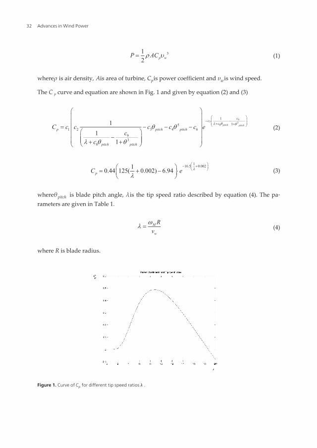
Figure 1. Curve of Cp for different tip speed ratios λ .
Advances in Wind Power32
The curve of Fig.1 has positive slope before Cp max and it has negative slope after Cp max.
3. One-Mass Shaft Wind Station Model
Induction machine equation is
me m m
dT T J Cdtw w- = + (5)
Where, Tmis the mechanical torque, Teis the generator torque, Cis the system drag coeffi‐cient and J is the total inertia.
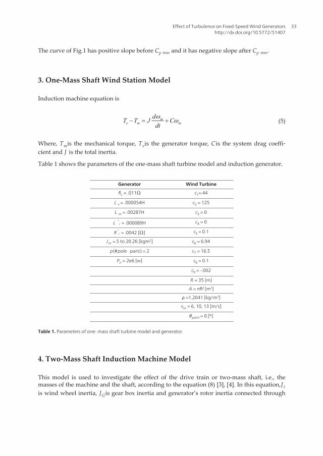
Table 1 shows the parameters of the one-mass shaft turbine model and induction generator.
Generator Wind Turbine
Rs = .011Ω c1=.44
L s = .000054H c2 = 125
L m = .00287H c3 = 0
L ′r = .000089H c4 = 0
R ′r = .0042 [Ω] c5 = 0.1
Jm =.5 to 20.26 [kgm2] c6 = 6.94
p(#pole pairs) = 2 c7 = 16.5
Pn = 2e6 [w] c6 = 0.1
c9 = -.002
R = 35 [m]
A = πR2 [m2]
ρ =1.2041 [kg/m3]
vw = 6, 10, 13 [m/s]
θpitch = 0 [º]
Table 1. Parameters of one- mass shaft turbine model and generator.
4. Two-Mass Shaft Induction Machine Model
This model is used to investigate the effect of the drive train or two-mass shaft, i.e., themasses of the machine and the shaft, according to the equation (8) [3], [4]. In this equation,J tis wind wheel inertia, JGis gear box inertia and generator’s rotor inertia connected through
Effect of Turbulence on Fixed-Speed Wind Generatorshttp://dx.doi.org/10.5772/51407
33

the elastic turbine shaft with a κ as an angular stiffness coefficient and C as an angulardamping coefficient.
The angular shaft speed ωt can be obtained from equations (6) and (7) [1], [3], [4].
TGis the torque of the machine, T tis the turbine torque, δtis the angular turbine shaft angle,δGis the angular generator shaft angle, νis the inverse of the gear box ratio and JGandJ t arethe inertia of the machine shaft and turbine shaft, respectively.
The Parameters, defined above, are given in Table 2.
This model is described as equation (8).
( ) ( )GG G t GB t GB
d CT Jdtw k d d w w
n n= - - - - (6)
( ) ( )tt t t GB t GB
dT J Cdtw k d d w w= + - + - (7)
2 2. . .1 0
1.
00 0
1 0 0 00 0
0 1 0 0
G GG G G GG
t t Gt
t t t tG G t
t t
C CJ J J J J
TC C JJ J J J T
n n n k nkw ww wn nk kw dw d
æ ö- - -æ öç ÷æ ö æ ö ç ÷ç ÷ç ÷ ç ÷ ç ÷ç ÷ æ ö- - -ç ÷ ç ÷ ç ÷= +ç ÷ ç ÷ç ÷ ç ÷ ç ÷è øç ÷ç ÷ ç ÷ ç ÷ç ÷ ç ÷ç ÷è ø è ø ç ÷ç ÷ è øç ÷
è ø
&&
(8)
υ 1/80
JG [kg.m2] .5
J t [kg.m2] 1
C [Nm/rad2] 1e6
κ [Nm/rad] 6e7
Table 2. Parameters of two-mass shaft model.
5. Induction Machine and Kloss Theory
In a single-fed induction machine, the torque angular speed curve of equation (12) [1] isnonlinear, but by using the Kloss equation (13), equations (9), (10), and (11), this curve is lin‐early modified [1], [2] as shown in Fig. 2. Therefore, the effect of frequency changes in windpower stations can be derived precisely by equation (12) and approximately using equation(13), as shown in Figs. 2–6.
Advances in Wind Power34

( )
22 2
222 2 2
ss ss
b
sm ss rr s rr
b
f R Xf
GfX X X R Xf
-æ ö
+ç ÷è ø= ±
æ ö¢ ¢- +ç ÷
è ø
(9)
k rs R G¢= (10)
( ) ( )
2 2
22 222
sm s
bk
s ss m ss rr ss s rr
b b
f X GVfT
f fR G X X X X GR Xf f
=æ öæ ö æ ö
¢ ¢ç ÷+ - + +ç ÷ ç ÷ç ÷è ø è øè ø
(11)
( ) ( )
2 2
22 222
sm r s
be
s ss m ss rr ss s rr
b b
f X R sVfT
f fR G X X X X GR Xf f
¢=æ öæ ö æ ö
¢ ¢ç ÷+ - + +ç ÷ ç ÷ç ÷è ø è øè ø
(12)
2 ; s<<sk e kk
sT Ts
= (13)
Figure 2. Electrical torque (nonlinear and linear) versus speed (slip).
Effect of Turbulence on Fixed-Speed Wind Generatorshttp://dx.doi.org/10.5772/51407
35

Equations (11) and (12) are given in per unit, but the associated resistances are in ohms.
Figure 3. Mechanical and linear electrical torque versus slip.
Figure 4. Mechanical and electrical torque versus frequency curves per unit with Vsag = 10% .
Advances in Wind Power36
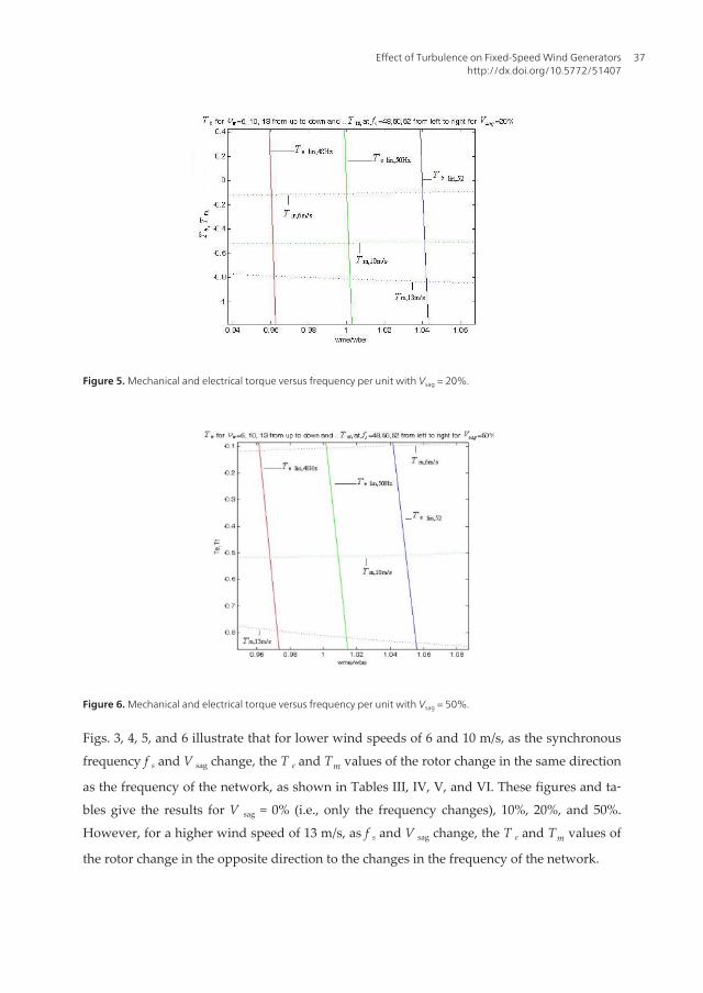
Figure 5. Mechanical and electrical torque versus frequency per unit with Vsag = 20%.
Figure 6. Mechanical and electrical torque versus frequency per unit with Vsag = 50%.
Figs. 3, 4, 5, and 6 illustrate that for lower wind speeds of 6 and 10 m/s, as the synchronous
frequency f s and V sag change, the T e and Tm values of the rotor change in the same direction
as the frequency of the network, as shown in Tables III, IV, V, and VI. These figures and ta‐
bles give the results for V sag = 0% (i.e., only the frequency changes), 10%, 20%, and 50%.
However, for a higher wind speed of 13 m/s, as f s and V sag change, the T e and Tm values of
the rotor change in the opposite direction to the changes in the frequency of the network.
Effect of Turbulence on Fixed-Speed Wind Generatorshttp://dx.doi.org/10.5772/51407
37

For small changes in the slip according to the Kloss approach in equation (13), the torque
changes as follows [2]:
1 0m mT T Ka w= + D(14)
Then:
01 2 1
e
k mm
k
TTs
w ww
æ ö+ D= -ç ÷ç ÷
è ø(15)
and
T TKal
w l w¶ ¶ 
= = ׶ ¶ 
(16)
or
0 0
40 , 0
0
1 12
pM
M
CK R v Ta w l nr
w l¶æ ö
= -ç ÷¶è ø(17)
Thus, the new angular operation speed[2] is
00 2 2
2
k k mm
k k e
k
k e
T TTs s
Tksa
www
w
- + -D =
+(18)
υw f s= 48 f s = 50 f s= 52
ωm pu Te pu ωm pu Te pu ωm pu Te pu
6 .96050 -.1157 1.0005 -.1064 1.0405 -.0974
10 .9621 -.5337 1.0021 -.491 1.0421 -.4493
13 .9631 -.7863 1.0035 -.8122 1.0439 -.8331
Table 3. Analytical MATLAB results for different frequencies.
Advances in Wind Power38

υw f s = 48 f s = 50 f s = 52
ωm pu Te pu ωm pu Te pu ωm pu Te pu
6 .9606 -.1156 1.0006 -.1064 1.0406 -.0974
10 .9625 -.5163 1.0027 -.5137 1.0429 -.5086
13 .9738 -.7868 1.0043 -.8127 1.0448 -.8335
Table 4. Analytical MATLAB results for V sag= 10%.
υw f s= 48 f s= 50 f s= 52
ωm pu Te pu ωm pu Te pu ωm pu Te pu
6 .9607 -.1156 1.0007 -.1064 1.0407 -.0974
10 .9632 -.5163 1.0034 -.5136 1.0437 -.5085
13 .9648 -.7875 1.0054 -.8134 1.0461 -.8341
Table 5. Analytical MATLAB results for V sag= 20%
υw f s= 48 f s= 50 f s= 52
ωm pu Te pu ωm pu Te pu ωm pu Te pu
6 .9618 -.1153 1.0018 -.1061 1.0418 -.0971
10 .9681 -.5161 1.0088 -.5131 1.0494 -.5076
13 .9724 -.7927 1.0139 -.8181 1.0555 -.8382
Table 6. Analytical MATLAB results for V sag= 50%
6. Simulation of wind generator with frequency change
During turbulence and changes in the grid frequency, the torque speed (slip) curves changein such a way that as the frequency increases, the torque is increased at low wind speeds; 6and 10 m/s, in contrast to Fig. 6 and decreases at a high speed of 13 m/s [2], as shown inTable 7 and Figs. 7–15.
υw f s = 48 f s = 50 f s = 52
ωm pu Te pu ωm pu Te pu ωm pu Te pu
6 .9619 -.1148 1.0019 -.1057 1.0418 -.0969
10 .9684 -.5179 1.0091 -.5134 1.0494 -.5076
13 .9724 -.7945 1.0147 -.8177 1.0559 -.8373
Table 7. Simulink simulation results for one- and two-mass shaft models
Effect of Turbulence on Fixed-Speed Wind Generatorshttp://dx.doi.org/10.5772/51407
39

Figs. 7–15 show the electrical torque and mechanical speed of the induction machine for
the one- and two-mass shaft turbine models at wind speeds of 6, 10, and 13 m/s to vali‐
date Table 7.
Figure 7. Electrical torque when = 48 and = 6m/s.
Figure 8. Electrical torque when f s= 50 and υw= 6m/s.
Advances in Wind Power40

Figure 9. Electrical torque when f s= 52 and υw= 6m/s.
Figure 10. Electrical torque when f s= 48 and υw= 10m/s.
Effect of Turbulence on Fixed-Speed Wind Generatorshttp://dx.doi.org/10.5772/51407
41

Figure 11. Electrical torque when f s= 50 and υw= 10m/s.
Figure 12. Electrical torque when f s= 52 and υw= 10m/s.
Advances in Wind Power42

Figure 13. Electrical torque when f s= 48 and υw= 13m/s.
Figure 14. Electrical torque when f s= 50 and υw= 13m/s.
Effect of Turbulence on Fixed-Speed Wind Generatorshttp://dx.doi.org/10.5772/51407
43

Figure 15. Electrical torque when f s= 52 and υw= 13m/s.
7. Simulation of wind station with one-mass and two-mass shaft turbinemodels
The results of simulations of a simple grid, fixed-speed induction machine, and one-massand two-mass shaft turbines are given in Tables 8 -10 and Figs. 16–42. For an induction windgenerator using the induction block in SIMULINK with high voltage sag i.e. 50% with fre‐quencies 50 and 52 and equal to 13, C p becomes negative, and the results are unrealistic.Then results of 50% voltage sag are realistic in new simulation of induction machine in Ta‐bles 8 -10.
υw f s= 48 f s= 50 f s= 52
ωm pu Te pu ωm pu Te pu ωm pu Te pu
6 .9624 -.1152 1.0024 -.106 1.0423 -.097
10 .9703 -.516 1.0111 -.5128 1.0519 -.5071
13 .9757 -.795 1.0176 -.8201 1.0595 -.8399
Table 8. Simulation results by SIMULINK for one and two mass shaft model for V sag= 10%
Advances in Wind Power44

υw f s= 48 f s= 50 f s= 52
ωm pu Te pu ωm pu Te pu ωm pu Te pu
6 .963 -.1151 1.003 -.1059 1.043 -.0969
10 .973 -.5159 1.014 -.5125 1.055 -.5066
13 .9799 -.7977 1.0223 -.8226 1.0648 -.842
Table 9. Simulation results by SIMULINK for one and two mass shaft model for V sag= 20%
υw f s= 48 f s= 50 f s= 52
ωm pu Te pu ωm pu Te pu ωm pu Te pu
6 .9674 -.114 1.0074 -.1048 1.0474 -.0959
10 .9933 -.5146 1.0364 -.5096 1.0796 -.502
13 1.0248 -.8239 1.0474 -.8347 1.0917 -.85
Table 10. Simulation results by SIMULINK for one and two mass shaft model for V sag= 50%
Figure 16. Torque-time in per unit while V sag= 10% and υw = 6m/s, f s=48
Effect of Turbulence on Fixed-Speed Wind Generatorshttp://dx.doi.org/10.5772/51407
45
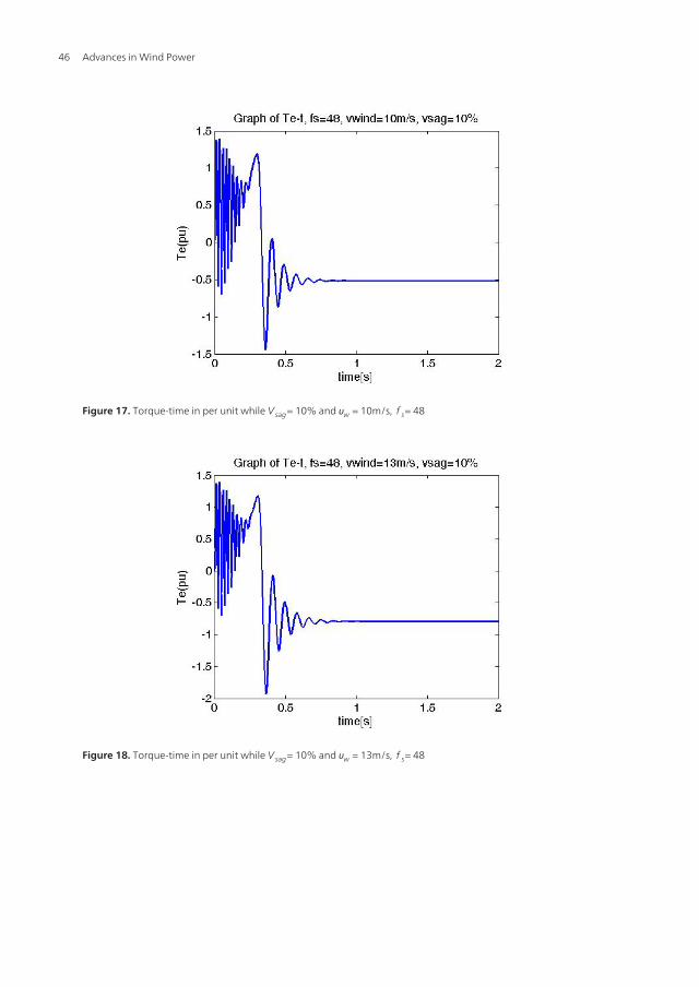
Figure 17. Torque-time in per unit while V sag= 10% and υw = 10m/s, f s= 48
Figure 18. Torque-time in per unit while V sag= 10% and υw = 13m/s, f s= 48
Advances in Wind Power46

Figure 19. Torque-time in per unit while V sag= 20% and υw = 6m/s, f s= 48
Figure 20. Torque-time in per unit while V sag= 20% and υw = 10m/s, f s= 48
Effect of Turbulence on Fixed-Speed Wind Generatorshttp://dx.doi.org/10.5772/51407
47
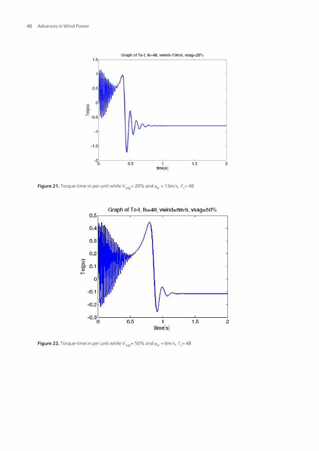
Figure 21. Torque-time in per unit while V sag= 20% and υw = 13m/s, f s= 48
Figure 22. Torque-time in per unit while V sag= 50% and υw = 6m/s, f s= 48
Advances in Wind Power48

Figure 23. Torque-time in per unit while V sag= 50% and υw = 10m/s, f s= 48
Figure 24. Torque-time in per unit while V sag= 50% and υw = 13m/s, f s= 48
Effect of Turbulence on Fixed-Speed Wind Generatorshttp://dx.doi.org/10.5772/51407
49
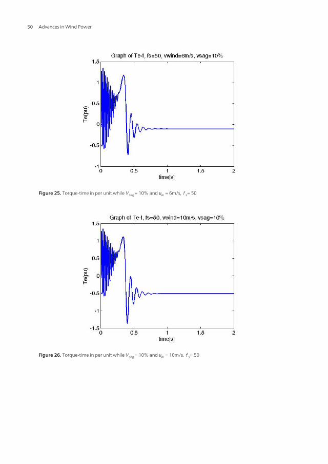
Figure 25. Torque-time in per unit while V sag= 10% and υw = 6m/s, f s= 50
Figure 26. Torque-time in per unit while V sag= 10% and υw = 10m/s, f s= 50
Advances in Wind Power50

Figure 27. Torque-time in per unit while V sag= 10% and υw = 13m/s, f s= 50
Figure 28. Torque-time in per unit while V sag= 20% and υw = 6m/s, f s= 50
Effect of Turbulence on Fixed-Speed Wind Generatorshttp://dx.doi.org/10.5772/51407
51

Figure 29. Torque-time in per unit while V sag= 20% and υw = 10m/s, f s= 50
Figure 30. Torque-time in per unit while V sag= 20% and υw = 13m/s, f s= 50
Advances in Wind Power52
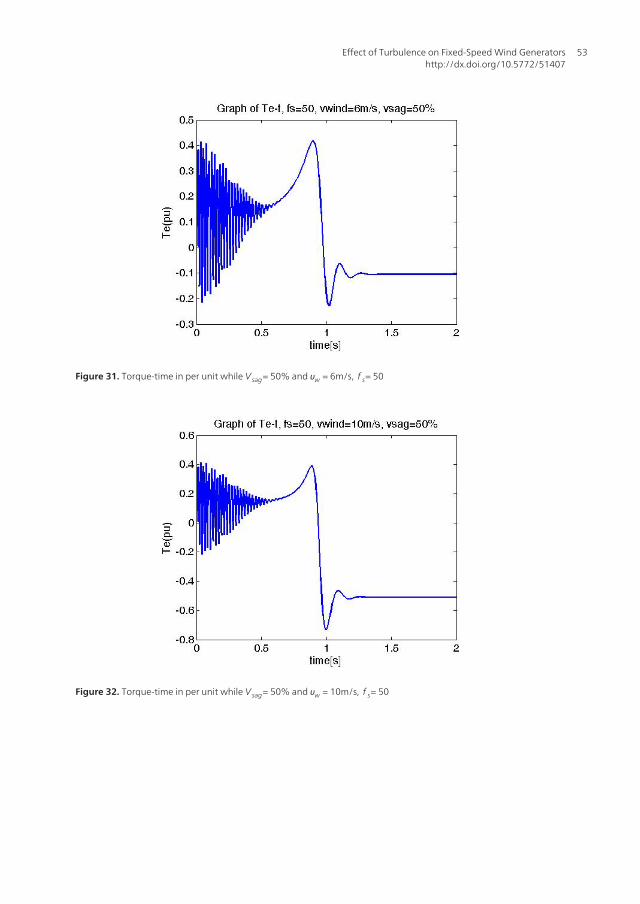
Figure 31. Torque-time in per unit while V sag= 50% and υw = 6m/s, f s= 50
Figure 32. Torque-time in per unit while V sag= 50% and υw = 10m/s, f s= 50
Effect of Turbulence on Fixed-Speed Wind Generatorshttp://dx.doi.org/10.5772/51407
53

Figure 33. Torque-time in per unit while V sag= 50% and υw = 13m/s, f s= 50 in new simulation of wind generator
Figure 34. Torque-time in per unit while V sag=10% and υw = 6m/s, f s= 52
Advances in Wind Power54

Figure 35. Torque-time in per unit while V sag=10% and υw = 10m/s, f s= 52
Figure 36. Torque-time in per unit while V sag= 10% and υw = 13m/s, f s= 52
Effect of Turbulence on Fixed-Speed Wind Generatorshttp://dx.doi.org/10.5772/51407
55
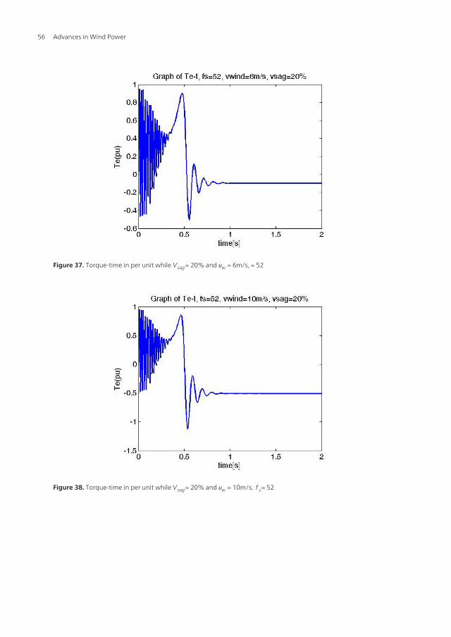
Figure 37. Torque-time in per unit while V sag= 20% and υw = 6m/s, = 52
Figure 38. Torque-time in per unit while V sag= 20% and υw = 10m/s, f s= 52
Advances in Wind Power56

Figure 39. Torque-time in per unit while V sag= 20% and υw = 13m/s, f s= 52
Figure 40. Torque-time in per unit while V sag= 50% and υw = 6m/s, f s= 52
Effect of Turbulence on Fixed-Speed Wind Generatorshttp://dx.doi.org/10.5772/51407
57
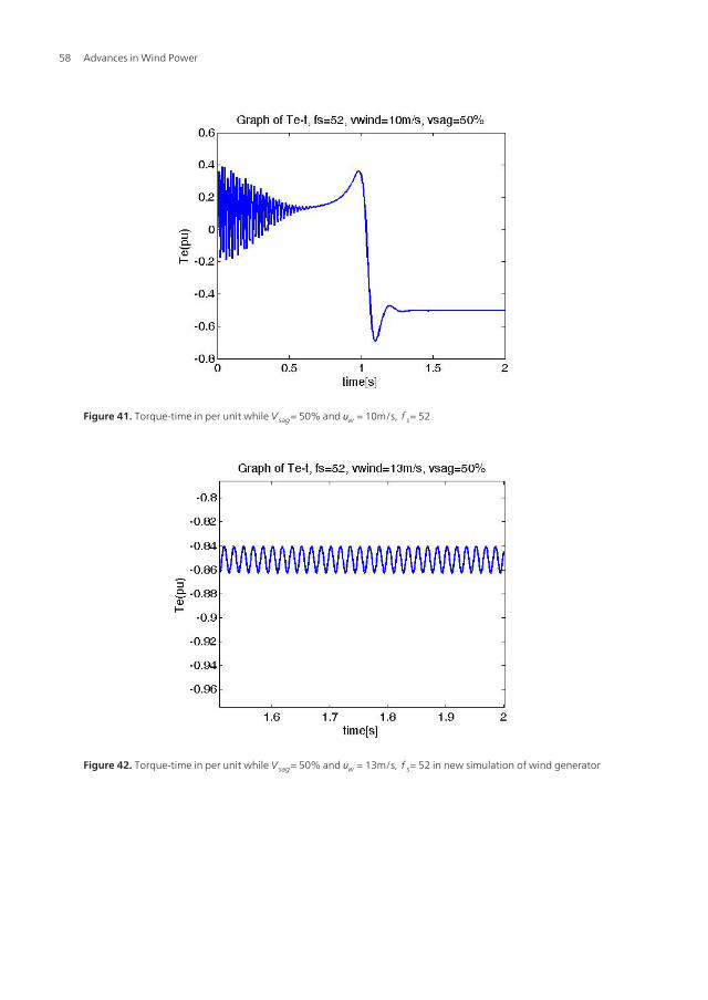
Figure 41. Torque-time in per unit while V sag= 50% and υw = 10m/s, f s= 52
Figure 42. Torque-time in per unit while V sag= 50% and υw = 13m/s, f s= 52 in new simulation of wind generator
Advances in Wind Power58
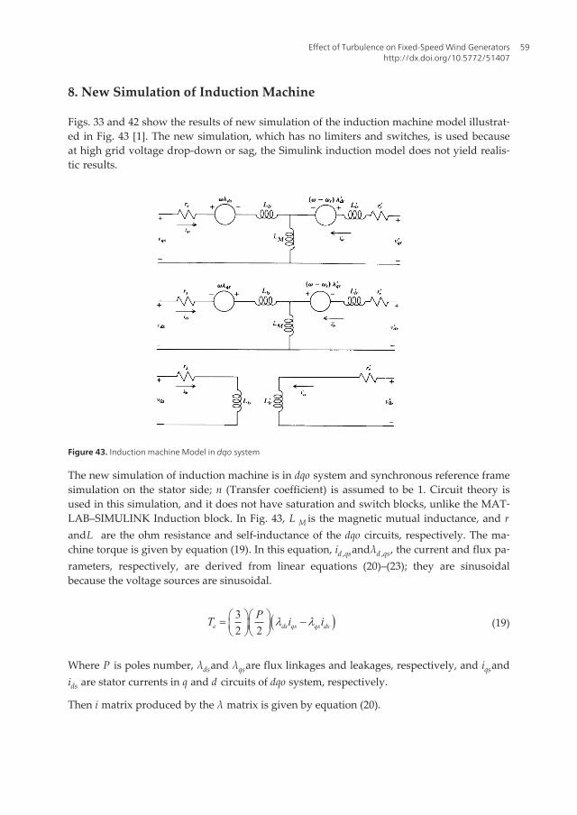
8. New Simulation of Induction Machine
Figs. 33 and 42 show the results of new simulation of the induction machine model illustrat‐ed in Fig. 43 [1]. The new simulation, which has no limiters and switches, is used becauseat high grid voltage drop-down or sag, the Simulink induction model does not yield realis‐tic results.
Figure 43. Induction machine Model in dqo system
The new simulation of induction machine is in dqo system and synchronous reference framesimulation on the stator side; n (Transfer coefficient) is assumed to be 1. Circuit theory isused in this simulation, and it does not have saturation and switch blocks, unlike the MAT‐LAB–SIMULINK Induction block. In Fig. 43, L M is the magnetic mutual inductance, and randL are the ohm resistance and self-inductance of the dqo circuits, respectively. The ma‐chine torque is given by equation (19). In this equation, id ,qsandλd ,qs, the current and flux pa‐rameters, respectively, are derived from linear equations (20)–(23); they are sinusoidalbecause the voltage sources are sinusoidal.
( )32 2e ds qs qs ds
PT i il læ öæ ö= -ç ÷ç ÷è øè ø
(19)
Where P is poles number, λdsand λqsare flux linkages and leakages, respectively, and iqsandids are stator currents in q and d circuits of dqo system, respectively.
Then i matrix produced by the λ matrix is given by equation (20).
Effect of Turbulence on Fixed-Speed Wind Generatorshttp://dx.doi.org/10.5772/51407
59

( ) ( )( ) ( ) ( )
1 1
1 1.qdos qdoss s s s sr r
Tqdor qdorr sr s r r r
iK L K K L KiK L K K L K
ll
- -
- -
é ù¢é ù é ùê ú=ê ú ê ú¢ ¢¢ ¢ê úë û ë ûë û
(20)
where the inductance matrix parameters are given by (21), (22), (23).
( ) 10 0
0 00 0
ls M
s s s ls M
ls
L LK L K L L
L
-
+é ùê ú= +ê úê úë û
(21)
( ) 10 0
0 00 0
lr M
r r r lr M
lr
L LK L K L L
L
-
¢ +é ùê ú¢ ¢= +ê ú
¢ê úë û
(22)
( ) ( ) ( )1 10 0
0 00 0 0
MT
s sr r r sr s M
LK L K K L K L- -
é ùê ú¢ ¢= = ê úê úë û
(23)
The linkage and leakage fluxes are given by (24) to (29).
( )qs ls qs M qs qrL i L i il ¢= + + (24)
( )ds ls ds M ds drL i L i il ¢= + + (25)
os ls osL il = (26)
( )qr lr qr M qs qrL i L i il¢ ¢ ¢ ¢= + + (27)
( )dr lr dr M ds drL i L i il¢ ¢ ¢ ¢= + + (28)
or lr orL il¢ ¢ ¢= (29)
Advances in Wind Power60

To create the torque in equation (19), it is necessary to determine the currents in equations(30)–(33) from the stator and rotor currents by using current meters.
qsqs s qs ds
dr i
dtl
n wl= + + (30)
dsds s ds qs
dr idtln wl= - + (31)
( ) qrqr r qr r dr
dr i
dtl
n w w l¢
¢ ¢ ¢ ¢= + - + (32)
( ) drdr r dr r qr
dr idtln w w l¢ ¢ ¢ ¢= - - + (33)
9. Conclusion
As frequency changes and voltage sag occurs because of turbulence in wind stations in ride-through faults, the system’s set point changes. The theoretical and simulation results resultsare similar for one mass shaft and two mass shaft turbine models. At lower wind speeds; 6and 10 m/s, the directions of the changes in the new working point are the same as those ofthe frequency changes. At a higher wind speed; 13 m/s, the directions of these changes areopposite to the direction of the frequency changes. Simulation results of high grid voltagesag with SIMULINK induction block has error and new simulation of wind induction gener‐ator in synchronous reference frame is presented without error and in 50% voltage sag, newsimulation of wind generator model has higher precision than that in 10% and 20% voltagesags; however, this model can simulate wind generator turbulence with voltage sags higherthan 50%. Although results of new simulation of induction machine with wind turbine for50% voltage sag and frequencies 50 and 52 have been presented in this chapter.
10. Nomenclature
P =Generator power
ρ =Air density
Effect of Turbulence on Fixed-Speed Wind Generatorshttp://dx.doi.org/10.5772/51407
61

A=Turbine rotor area
Cp =Power Coefficient
υw =Wind speed
θpitch =Pitch angle
Te =Electrical torque
Tm =Mechanical torque
J = Inertia
ωm =Mechanical speed
C =Drag coefficient
ν =Gear box ration
R =Blade radius
Rs = Stator resistance
L s = Stator inductance
L m = Mutual inductance
L ′r = Rotor inductance
R ′r = Rotor resistance
p =Pole pairs
κ =Stiffness
λr ,s =Rotor and stator flux
Kr ,s =Rotor and stator park transformation in synchronous reference frame
ir ,s =Rotor and stator current
vr ,s =Rotor and stator voltage
11. Future Work
The new simulation of induction generator will be tested by new innovative rain turbinetheory and model of the author.
Advances in Wind Power62

Acknowledgements
I appreciate Dr. Oriol Gomis Bellmunt for conceptualization, Discussions and new informa‐
tion and Dr. Andreas Sumper for discussions about first part of chapter, with special thanks
to Dr. Joaquin Pedra for checking reference frame and starting point in new simulation of
induction machine.
Author details
Hengameh Kojooyan Jafari*
Address all correspondence to: [email protected]
Department of Electrical Engineering, Islamic Azad University, Islamshahr Branch, Iran
References
[1] Krause, Paul C. (1986). Analysis of Electric Machinery. MCGraw-Hill, Inc.
[2] Sunmper, A., Gomis-Bellmunt, O., Sudria-Andreu, A., et al. (2009). Response of Fixed
Speed Wind Turbines to System Frequency Disturbances. ICEE Transaction on Power
Systems, 24(1), 181-192.
[3] Junyent-Ferre, A., Gomis-Bellmunt, O., Sunmper, A., et al. (2010). Modeling and con‐
trol of the doubly fed induction generator wind turbine. Simulation modeling practice
and theory journal of ELSEVIER, 1365-1381.
[4] Lubosny, Z. (2003). Wind Turbine operation in electric power systems. Springer pub‐
lisher.
Effect of Turbulence on Fixed-Speed Wind Generatorshttp://dx.doi.org/10.5772/51407
63

Advances in Wind Power64
Related Documents

![in Bose systems - Isaac Newton Institute€¦ · · 2014-05-31Lecture Notes: arXiv:1302.1448 [cond-mat.quant-gas] Non-Thermal Fixed Points – Universality, topology & turbulence](https://static.cupdf.com/doc/110x72/5b0438877f8b9a89208d4376/in-bose-systems-isaac-newton-institute-2014-05-31lecture-notes-arxiv13021448.jpg)