Effect of reinforcement ratios on shear behavior of concrete beams strengthened with CFRP sheets Bashir H. Osman, Erjun Wu * , Bohai Ji, Suhaib S. Abdulhameed College of Civil and Transportation Engineering, Hohai Univ., Nanjing 210098, China Received 10 August 2015; revised 1 March 2016; accepted 2 April 2016 KEYWORDS RC beams; CFRP; Reinforcement ratio; Shear and flexural; Cracks behavior; ANSYS14 Abstract Carbon fiber reinforcement polymer (CFRP) sheets are the most commonly materials that are used to strengthen reinforced concrete members due to high strength-to-weight ratio, excel- lent mechanical strength, and good fatigue properties. In this research program seven reinforced concrete beams were tested under four points loading with different shear span-to-depth ratios av d , longitudinal and vertical reinforcement ratios. A numerical analysis using ANSYS software program was done by modeling 27 reinforced concrete beams with and without CFRP sheets. The beam dimensions, concrete strength, strengthening configuration of the CFRP sheets (full wrapped, U shape, and side bonding), and FRP thickness were considered as the main parameters of the numerical analysis. A comparison between the finite element (FE) results and the ACI stan- dard code demonstrated the validity of the computational models in capturing the structural response of FRP contribution with variation varied from (10–16)%, (12–20)% and (13–19)% for full wrapping, U-jacketing, and side bonding, respectively. The finite element models were able to accurately predict the load capacities for the simulated RC beams strengthened in shear with CFRP composites. The results obtained using ANSYS finite element are relatively identical to the experimental ones, showing reasonable agreement with variation not more than 5% in all the specimens. Ó 2016 Housing and Building National Research Center. Production and hosting by Elsevier B.V. This is an open access article under the CC BY-NC-ND license (http://creativecommons.org/licenses/by-nc-nd/4.0/). Introduction Reinforced concrete structures are widely used in civil engi- neering construction. Most of these structures may become deteriorated with time due to corrosion, freezing and thawing cycle, sulfate attack, and physical damage from impacts. Such deterioration may lead to inadequate flexural or shear strength of the concrete structure. The influence of reinforced concrete (RC) beam dimensions and effectiveness of stirrups in transfer- ring shear across a diagonal crack were widely investigated by Tompos and Frosh [1], Bazant and Kim [2] and Godat et al. * Corresponding author. E-mail addresses: [email protected] (B.H. Osman), wwwerjun@ hotmail.com (E. Wu), [email protected] (B. Ji), [email protected] (S.S. Abdulhameed). Peer review under responsibility of Housing and Building National Research Center. Production and hosting by Elsevier HBRC Journal (2016) xxx, xxx–xxx Housing and Building National Research Center HBRC Journal http://ees.elsevier.com/hbrcj http://dx.doi.org/10.1016/j.hbrcj.2016.04.002 1687-4048 Ó 2016 Housing and Building National Research Center. Production and hosting by Elsevier B.V. This is an open access article under the CC BY-NC-ND license (http://creativecommons.org/licenses/by-nc-nd/4.0/). Please cite this article in press as: B.H. Osman et al., Effect of reinforcement ratios on shear behavior of concrete beams strengthened with CFRP sheets, HBRC Journal (2016), http://dx.doi.org/10.1016/j.hbrcj.2016.04.002

Welcome message from author
This document is posted to help you gain knowledge. Please leave a comment to let me know what you think about it! Share it to your friends and learn new things together.
Transcript
HBRC Journal (2016) xxx, xxx–xxx
Housing and Building National Research Center
HBRC Journal
http://ees.elsevier.com/hbrcj
Effect of reinforcement ratios on shear behavior of
concrete beams strengthened with CFRP sheets
* Corresponding author.
E-mail addresses: [email protected] (B.H. Osman), wwwerjun@
hotmail.com (E. Wu), [email protected] (B. Ji), [email protected]
(S.S. Abdulhameed).
Peer review under responsibility of Housing and Building National
Research Center.
Production and hosting by Elsevier
http://dx.doi.org/10.1016/j.hbrcj.2016.04.0021687-4048 � 2016 Housing and Building National Research Center. Production and hosting by Elsevier B.V.This is an open access article under the CC BY-NC-ND license (http://creativecommons.org/licenses/by-nc-nd/4.0/).
Please cite this article in press as: B.H. Osman et al., Effect of reinforcement ratios on shear behavior of concrete beams strengthened with CFRP sheets,Journal (2016), http://dx.doi.org/10.1016/j.hbrcj.2016.04.002
Bashir H. Osman, Erjun Wu *, Bohai Ji, Suhaib S. Abdulhameed
College of Civil and Transportation Engineering, Hohai Univ., Nanjing 210098, China
Received 10 August 2015; revised 1 March 2016; accepted 2 April 2016
KEYWORDS
RC beams;
CFRP;
Reinforcement ratio;
Shear and flexural;
Cracks behavior;
ANSYS14
Abstract Carbon fiber reinforcement polymer (CFRP) sheets are the most commonly materials
that are used to strengthen reinforced concrete members due to high strength-to-weight ratio, excel-
lent mechanical strength, and good fatigue properties. In this research program seven reinforced
concrete beams were tested under four points loading with different shear span-to-depth ratiosavd
� �, longitudinal and vertical reinforcement ratios. A numerical analysis using ANSYS software
program was done by modeling 27 reinforced concrete beams with and without CFRP sheets.
The beam dimensions, concrete strength, strengthening configuration of the CFRP sheets (full
wrapped, U shape, and side bonding), and FRP thickness were considered as the main parameters
of the numerical analysis. A comparison between the finite element (FE) results and the ACI stan-
dard code demonstrated the validity of the computational models in capturing the structural
response of FRP contribution with variation varied from (10–16)%, (12–20)% and (13–19)% for
full wrapping, U-jacketing, and side bonding, respectively. The finite element models were able
to accurately predict the load capacities for the simulated RC beams strengthened in shear with
CFRP composites. The results obtained using ANSYS finite element are relatively identical to
the experimental ones, showing reasonable agreement with variation not more than 5% in all the
specimens.� 2016 Housing and Building National Research Center. Production and hosting by Elsevier B.V. This is
an open access article under the CCBY-NC-ND license (http://creativecommons.org/licenses/by-nc-nd/4.0/).
Introduction
Reinforced concrete structures are widely used in civil engi-neering construction. Most of these structures may become
deteriorated with time due to corrosion, freezing and thawingcycle, sulfate attack, and physical damage from impacts. Suchdeterioration may lead to inadequate flexural or shear strength
of the concrete structure. The influence of reinforced concrete(RC) beam dimensions and effectiveness of stirrups in transfer-ring shear across a diagonal crack were widely investigated byTompos and Frosh [1], Bazant and Kim [2] and Godat et al.
HBRC

Table 1 Specimen details.
No Specimen avd Bott. steel Top steel Stirrup
1 RC0 1.5 2Ø12 2Ø10 –
2 RC1 1.5 2Ø12 2Ø10 Ø6@150
3 RC2 1.5 4Ø12 2Ø10 Ø6@150
4 RC3 1.5 6Ø12 2Ø10 Ø6@150
5 RC4 2.00 6Ø12 2Ø10 Ø6@150
6 RC5 2.00 6Ø12 2Ø10 Ø6@100
7 RC6 1.5 6Ø12 2Ø10 Ø6@100
2 B.H. Osman et al.
[3]. Their results showed that the stirrups developed length candirectly influence on shear strength while closed stirrups mayhave a significant influence on the strength contribution attrib-
uted to the stirrups. Moreover, the effect of reinforcementratio in crack behaviors was carried out, and an algorithm withsimplified formulas for estimating the relationship between the
tension reinforcement and ductility of reinforced concretebeams was presented in Lee and Pan [4]. To evaluate the effec-tive shear reinforcement pattern, a nonlinear analysis on RC
beams with different shear reinforcement patterns using finiteelement analysis was conducted [5]. They also compared theexisting variation in behaviors of reinforced concrete beamwith and without shear reinforcement to that obtained from
finite element simulation. Their results showed that all typesof web reinforcements have almost similar effect for staticloading condition.
Experimental and analytical studies regarding various con-figurations of FRP sheets to increase the strengthening effectof RC beams have been reported. For the length and anchor-
age length of CFRP, it has been recommended to use equa-tions for the effective bond length from ACI repair manual[6]. However, experimental results have shown that the FRP
length has no greater effect on structural behavior of RCbeams when the FRP length is more than 60% of the spanlength of the beam [7,8]. The relationship between debondingand CFRP thickness is investigated experimentally [9,10]. They
performed experiments to show the relationship betweenCFRP thickness and interfacial stress, and conclude that inter-facial stress increases with the number of CFRP layers
increased. Moreover, Brena and Marcri [11] investigated theeffect of CFRP width on the structural behavior of RC beams.
The understanding of the shear resisting mechanisms in RC
beams shear-strengthened by externally bonded fiber-reinforced polymer (FRP) sheets using finite element analysiswas studied [12–14]. The presence of FRP reinforcements mod-
ifies the inclinations of cracks and struts, the concrete confine-ment stresses, and other parameters related to the shearresponse [15,16]. This directly produces an interaction betweenthe concrete, internal steel, and FRP components of the shear
strength.The main contribution of this paper is to experimentally
investigate the effect of reinforcement ratios and FRP
strengthening on the shear behavior of reinforced concretebeams under four points loading. Moreover, the theoreticalmodel of the ACI code for prediction of the behavior of the
RC beam is experimentally validated. The beams were rein-forced with different levels of steel reinforcement ratios and
Figure 1 Geometry and cros
Please cite this article in press as: B.H. Osman et al., Effect of reinforcement ratiosJournal (2016), http://dx.doi.org/10.1016/j.hbrcj.2016.04.002
shear span-to-depth ratio avd
� �. The shear behavior was studied
in terms of ultimate load, cracking load, crack patterns, and
failure modes.
Experimental program
Details of tested beams
All reinforced concrete beams were constructed with a rectan-gular cross section of 100 mm wide, 300 mm high, and a totallength of 1500 mm. One of these beams (beam RC0) was con-sidered as a control beam, while beams (RC1–RC6) were rein-
forced with different reinforcement ratios. Beams (RC0 andRC1) were reinforced with 2Ø12 mm, Beam RC2 was rein-forced with 4Ø12 mm, and Beams (RC3–RC6) were reinforced
with 6Ø12 mm deformed bars at the tension face, while all thebeams were reinforced with 2Ø10 mm deformed bars at thecompression face. The Control beam (RC0) was left without
shear reinforcement, while the remaining beams were providedwith shear reinforcements consisting of Ø6 mm reinforcing barstirrups at a center-to-center spacing of 150 mm, and 100 mm
for beams (RC1–RC4) and (RC5 and RC6), respectively. The
effective span-to-depth ratios avd
� �were 1.5 for beams RC0–
RC3 and RC6, while the avd
was 2.0 for beams RC5 and
RC6. The clear concrete cover to the reinforcement bars was20 mm. Details of the tension, compression, and steel stirrups
reinforcements are described in Fig. 1 and Table 1.
Material properties
Properties of the materials used in this research were obtainedexperimentally. The average concrete compressive strengthwas 33 MPa. The yield strength of the longitudinal and vertical
s sections of tested beam.
on shear behavior of concrete beams strengthened with CFRP sheets, HBRC
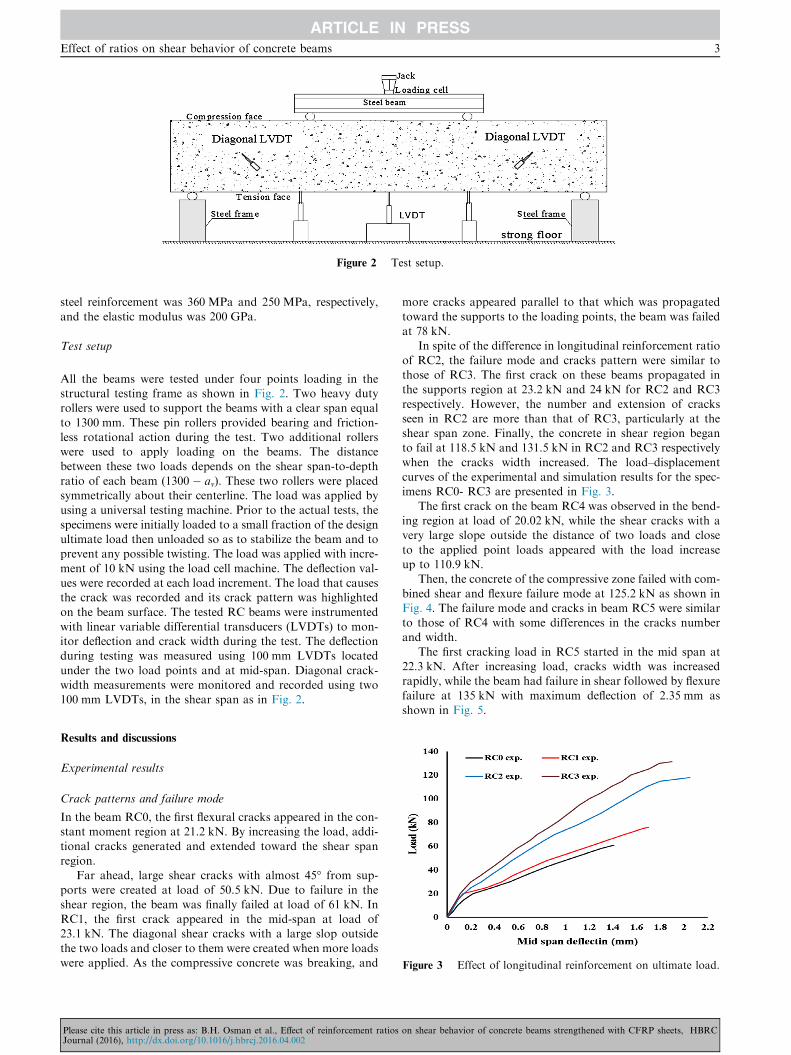
Figure 2 Test setup.
Effect of ratios on shear behavior of concrete beams 3
steel reinforcement was 360 MPa and 250 MPa, respectively,
and the elastic modulus was 200 GPa.
Test setup
All the beams were tested under four points loading in thestructural testing frame as shown in Fig. 2. Two heavy dutyrollers were used to support the beams with a clear span equal
to 1300 mm. These pin rollers provided bearing and friction-less rotational action during the test. Two additional rollerswere used to apply loading on the beams. The distancebetween these two loads depends on the shear span-to-depth
ratio of each beam (1300 � av). These two rollers were placedsymmetrically about their centerline. The load was applied byusing a universal testing machine. Prior to the actual tests, the
specimens were initially loaded to a small fraction of the designultimate load then unloaded so as to stabilize the beam and toprevent any possible twisting. The load was applied with incre-
ment of 10 kN using the load cell machine. The deflection val-ues were recorded at each load increment. The load that causesthe crack was recorded and its crack pattern was highlighted
on the beam surface. The tested RC beams were instrumentedwith linear variable differential transducers (LVDTs) to mon-itor deflection and crack width during the test. The deflectionduring testing was measured using 100 mm LVDTs located
under the two load points and at mid-span. Diagonal crack-width measurements were monitored and recorded using two100 mm LVDTs, in the shear span as in Fig. 2.
Figure 3 Effect of longitudinal reinforcement on ultimate load.
Results and discussions
Experimental results
Crack patterns and failure mode
In the beam RC0, the first flexural cracks appeared in the con-stant moment region at 21.2 kN. By increasing the load, addi-
tional cracks generated and extended toward the shear spanregion.
Far ahead, large shear cracks with almost 45� from sup-ports were created at load of 50.5 kN. Due to failure in the
shear region, the beam was finally failed at load of 61 kN. InRC1, the first crack appeared in the mid-span at load of23.1 kN. The diagonal shear cracks with a large slop outside
the two loads and closer to them were created when more loadswere applied. As the compressive concrete was breaking, and
Please cite this article in press as: B.H. Osman et al., Effect of reinforcement ratiosJournal (2016), http://dx.doi.org/10.1016/j.hbrcj.2016.04.002
more cracks appeared parallel to that which was propagated
toward the supports to the loading points, the beam was failedat 78 kN.
In spite of the difference in longitudinal reinforcement ratio
of RC2, the failure mode and cracks pattern were similar tothose of RC3. The first crack on these beams propagated inthe supports region at 23.2 kN and 24 kN for RC2 and RC3
respectively. However, the number and extension of cracksseen in RC2 are more than that of RC3, particularly at theshear span zone. Finally, the concrete in shear region beganto fail at 118.5 kN and 131.5 kN in RC2 and RC3 respectively
when the cracks width increased. The load–displacementcurves of the experimental and simulation results for the spec-imens RC0- RC3 are presented in Fig. 3.
The first crack on the beam RC4 was observed in the bend-ing region at load of 20.02 kN, while the shear cracks with avery large slope outside the distance of two loads and close
to the applied point loads appeared with the load increaseup to 110.9 kN.
Then, the concrete of the compressive zone failed with com-
bined shear and flexure failure mode at 125.2 kN as shown inFig. 4. The failure mode and cracks in beam RC5 were similarto those of RC4 with some differences in the cracks numberand width.
The first cracking load in RC5 started in the mid span at22.3 kN. After increasing load, cracks width was increasedrapidly, while the beam had failure in shear followed by flexure
failure at 135 kN with maximum deflection of 2.35 mm asshown in Fig. 5.
on shear behavior of concrete beams strengthened with CFRP sheets, HBRC

Figure 4 Effect of transverse reinforcement on ultimate load and
deflection.
Figure 5 Effect of span-to-depth ratio on ultimate load.
Figure 6 Sample of load versus the crack width of four tested
beams.
4 B.H. Osman et al.
In beam RC6, it can be observed that the cracks were con-siderably smaller than that of the other beams while the crack
shape is similar to that of RC5, however, at earlier loadingvalue of 22.15 kN. After increasing load, the concrete in thecompressive area started to fail and the failure crack initiated
at the support point and propagated toward the loading pointat 157.03 kN. The value of failure loads in this beam washigher than all test beams.
From the above observations, the cracks width of speci-mens indicates that the use of longitudinal reinforcement ratiohas a significant effect on the crack width and space at everyload stages. It is obvious that wider cracks were considerably
measured in specimens with lower shear reinforcement thanthat with higher reinforcement ratio values. Fig. 6 shows thesample of the load versus the crack width of four tested beams.
The beams with additional tension reinforcement displayedbetter cracking control than that of control beam by decreas-ing the cracks width and increasing the spacing between the
cracks. The cracks patterns of tested beam are illustrated inFig. 7.
Numerical modeling
A finite element (FE) analysis using ANSYS [17] computerprogram was used to analysis the reinforced concrete (RC)
Please cite this article in press as: B.H. Osman et al., Effect of reinforcement ratiosJournal (2016), http://dx.doi.org/10.1016/j.hbrcj.2016.04.002
beams. The numerical simulation was divided into two groups.The first group consisted on the calibration of the numericalmodels with the experimental results, while the second group
was investigated the effect of beam depth, concrete strength,CFRP sheet configuration, and CFRP sheet thickness on thebehavior of reinforced concrete beams strengthened with
CFRP sheets.SOLID65 element, was used to model the concrete, and this
element is capable of cracking in tension and crushing in com-
pression. The element is defined by eight nodes having threedegrees of freedom at each node: translations of the nodes inx, y, and z-directions.
An eight-node solid element, solid 45, was used to simulate
the steel plates in the supports and the loading points. Theelement is defined with eight nodes having three degrees offreedom at each node translation in the nodal x-, y-, and
z-directions.A link 8 element was used to model steel reinforcement.
This element is a 3D spar element and it has two nodes with
three degrees of freedom in each node The finite element modelfor the rebar was assumed to be a bilinear isotropic, elastic-perfectly plastic material, and identical in tension andcompression.
A layered solid element, Solid 46, was used to model theFRP sheet. The element allows for different material layerswith different orientations and orthotropic material properties
in each layer. The element has three degrees of freedom at eachnode. Eqs. (1) and (2) show the relationship between mxy andmyx:
1� v2xyEy
Ex
� �� v2yz
Ez
Ey
� �� v2xz
Ez
Ex
� �� 2vxyvyzvxz
Ez
Ex
� �
¼ positive ð1Þ
Gxy ¼ Gxz ¼ ExEy
Ex þ Ey þ 2vxyEx
; Gyz ¼ Ez or Ey
2ð1þ vyzÞ and
vyx ¼ Ey
Ex
vxy ð2Þ
In the present study, the linear elastic properties of FRP
composites are assumed. Poisson’s ratios of: mxy = mxz = 0.22and myz = 0.30, which are widely used in previously publishedliterature on this subject, are adopted. The contact between
FRP and concrete is modeled by contact elements TARGE170and CONTA174 (ANSYS 14) [15,18]. In studying the contact
on shear behavior of concrete beams strengthened with CFRP sheets, HBRC
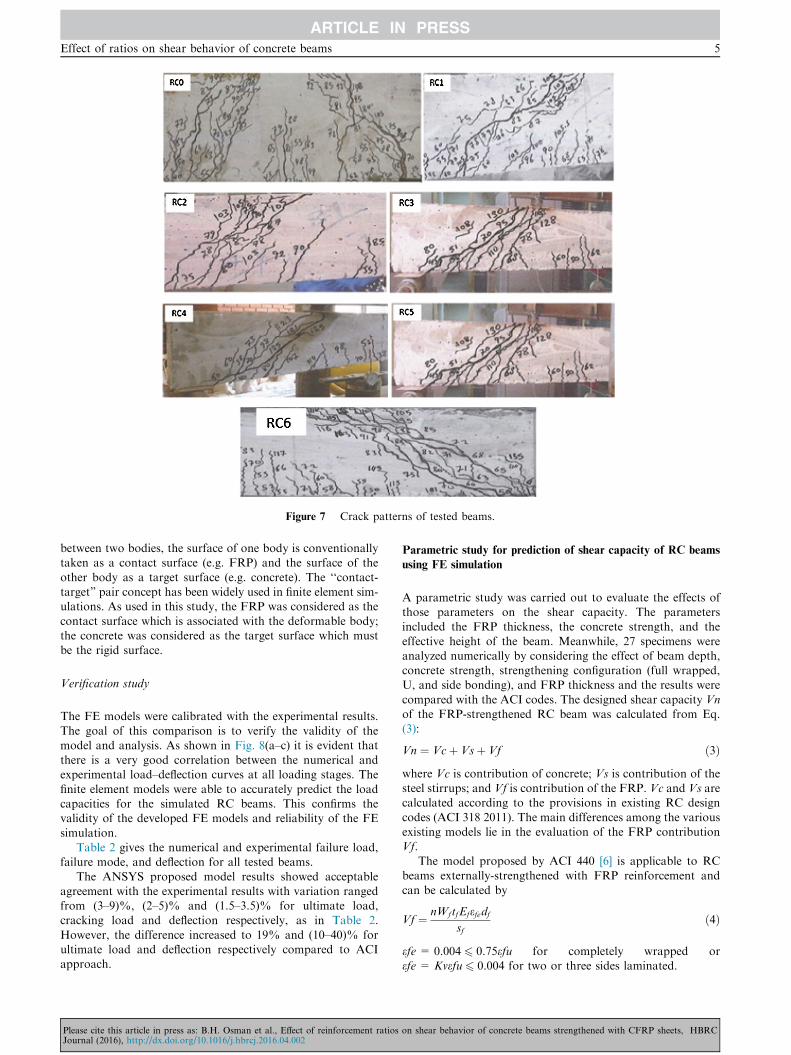
Figure 7 Crack patterns of tested beams.
Effect of ratios on shear behavior of concrete beams 5
between two bodies, the surface of one body is conventionallytaken as a contact surface (e.g. FRP) and the surface of the
other body as a target surface (e.g. concrete). The ‘‘contact-target” pair concept has been widely used in finite element sim-ulations. As used in this study, the FRP was considered as the
contact surface which is associated with the deformable body;the concrete was considered as the target surface which mustbe the rigid surface.
Verification study
The FE models were calibrated with the experimental results.The goal of this comparison is to verify the validity of the
model and analysis. As shown in Fig. 8(a–c) it is evident thatthere is a very good correlation between the numerical andexperimental load–deflection curves at all loading stages. The
finite element models were able to accurately predict the loadcapacities for the simulated RC beams. This confirms thevalidity of the developed FE models and reliability of the FE
simulation.Table 2 gives the numerical and experimental failure load,
failure mode, and deflection for all tested beams.
The ANSYS proposed model results showed acceptableagreement with the experimental results with variation rangedfrom (3–9)%, (2–5)% and (1.5–3.5)% for ultimate load,cracking load and deflection respectively, as in Table 2.
However, the difference increased to 19% and (10–40)% forultimate load and deflection respectively compared to ACIapproach.
Please cite this article in press as: B.H. Osman et al., Effect of reinforcement ratiosJournal (2016), http://dx.doi.org/10.1016/j.hbrcj.2016.04.002
Parametric study for prediction of shear capacity of RC beams
using FE simulation
A parametric study was carried out to evaluate the effects ofthose parameters on the shear capacity. The parametersincluded the FRP thickness, the concrete strength, and the
effective height of the beam. Meanwhile, 27 specimens wereanalyzed numerically by considering the effect of beam depth,concrete strength, strengthening configuration (full wrapped,U, and side bonding), and FRP thickness and the results were
compared with the ACI codes. The designed shear capacity Vnof the FRP-strengthened RC beam was calculated from Eq.(3):
Vn ¼ Vcþ Vsþ Vf ð3Þwhere Vc is contribution of concrete; Vs is contribution of thesteel stirrups; and Vf is contribution of the FRP. Vc and Vs arecalculated according to the provisions in existing RC design
codes (ACI 318 2011). The main differences among the variousexisting models lie in the evaluation of the FRP contributionVf.
The model proposed by ACI 440 [6] is applicable to RC
beams externally-strengthened with FRP reinforcement andcan be calculated by
Vf ¼ nWftfEfefedfsf
ð4Þ
efe = 0.004 6 0.75efu for completely wrapped orefe= Kvefu 6 0.004 for two or three sides laminated.
on shear behavior of concrete beams strengthened with CFRP sheets, HBRC

Figure 8 Load deflection curve for FE verification.
Table 2 Summary of experimental, ANSYS finite element and ACI results with failure mode.
Beam
No
avd Ultimate load (P) Ultimate deflection (mm) Cracking load (Pcr) Pexp./
PANSYS
Pexp./
PACI
Mode of
failure
Pexp.
(kN)
PANSYS
(kN)
PACI
(ACI)
Defexp.(mm)
DefANSYS
(mm)
DefACI(mm)
Pcrexp.(kN)
PcrANSYS
(kN)
RC0 1.5 61 65.5 58.30 1.41 1.39 0.83 21.2 21.74 0.93 1.04 S* & F
RC1 1.5 78 84.5 103.02 1.85 1.93 1.40 23 23.54 0.92 0.76 S*
RC2 1.5 118 135 112.44 2.05 1.98 1.53 23.2 24.01 0.87 1.04 S*
RC3 1.5 131.5 140.6 119.10 1.90 1.77 1.62 24 24.5 0.94 1.10 S*
RC4 2 125.1 130.4 111.28 2.25 2.04 1.51 20 20.3 0.96 1.12 S* & F
RC5 2 135 145.03 133.60 2.35 2.28 1.82 22.3 23 0.93 1.01 S* & F
RC6 1.5 157 163.1 139.50 2.15 2.09 1.90 22.2 23.5 0.96 1.13 S*
* S = Shear, F = Flexure.
6 B.H. Osman et al.
Kv ¼ k1k2Le
11; 900efu6 0:75; Le ¼ 23; 300
ðtfEfÞ0:58 ; k1 ¼ fc
27
� �23
ð5Þ
k2 ¼ ðdf� LeÞdf
for U-jacketing; k2
¼ ðdf� 2LeÞdf
for two sides laminated
where df= depth of FRP shear reinforcement, Ef = tensile
modulus of elasticity of FRP, k1 = modification factorapplied to kv to account for the concrete strength, k2 = mod-ification factor applied to kv to account for the wrappingscheme, Le = active bond length of FRP laminate,
Please cite this article in press as: B.H. Osman et al., Effect of reinforcement ratiosJournal (2016), http://dx.doi.org/10.1016/j.hbrcj.2016.04.002
n= number of plies of FRP reinforcement, wf =width ofthe FRP reinforcing plies, efe= effective strain level in FRPreinforcement; strain level attained at section failure, efu =design rupture strain of FRP reinforcement, sf= spacing
FRP shear reinforcing, and fc= compressive stress in concrete.
Influence of the FRP thickness
The thickness (tf) of FRP is the main factor that directlyaffects the strength and the stiffness of the strengtheningmaterial. The variations of the predicted FRP contribution
versus FRP thickness for design guidelines are shown inFig. 9.
on shear behavior of concrete beams strengthened with CFRP sheets, HBRC

Figure 9 Influence of the FRP thickness by the existing models
and the FE simulations.
Figure 11 Influence of the beam depth by the existing models
and the FE simulations.
Effect of ratios on shear behavior of concrete beams 7
The predicted results were in good agreement with the ACIresults with variation not more than 16%, 20% and 19% forfull warp, U, and side bond, respectively.
Influence of concrete strength
The concrete strength is also an important factor that directly
affects the strength and the stiffness of the strengthening mate-rial. The variations of the predicted FRP contributions versusconcrete strength for design guidelines are shown in Fig. 10. A
comparison between the FE results and the ACI standard codedemonstrated the validity of the computational models in cap-turing the structural response with variation not more than11%, 18% and 15% for full warp, U, and side bond,
respectively.
Influence of the beam depth
It is adopted that the shear capacity of the completely-wrappedbeam is affected by the increase in the height of the FRP sheetmore than U and side bonds as shown in Fig. 11. The predicted
results from FE were in good agreement with the ACI coderesults with variation not more than 10%, 12% and 13% forfull warp, U, and side bond, respectively.
Figure 10 Influence of the concrete strength as predicted by the
existing models and the FE simulations.
Please cite this article in press as: B.H. Osman et al., Effect of reinforcement ratiosJournal (2016), http://dx.doi.org/10.1016/j.hbrcj.2016.04.002
Conclusion
In this paper, seven reinforced concrete (RC) beams underfour-point loading with different shear span-to-depth ratios,
longitudinal and vertical reinforcement ratios were experimen-tally investigated. The FE simulation approach was adopted topredict the contribution of side bonding, U-jacketing and full
wrapping FRP to the shear capacity of the RC beams. Para-metric studies were conducted to evaluate the importance ofdifferent parameters that affect the shear capacity of the RC
beam. It is obvious that as the longitudinal reinforcement ratiois increased, there is a small increase in the concrete shearstrength, owing to the low contribution of longitudinal steel
in the shear capacity of the beams loaded on shear zone. More-over, the stirrups reinforcement ratio has a great influence onthe shear strength and cracks depth than other parameters.The primary shear crack inclination affects the shear strength
contribution of the shear reinforcement. Furthermore, as theshear crack angle determines the number of stirrups intersectedby the crack, the stirrup directly affects the shear strength. It
has been further shown that the low reinforcement ratiosdirectly reduce the shear strengths of the specimens andincrease the crack widths. All specimens show that the effect
of the reinforcement ratio on shear strength and deflectionwas considerably greater than that predicted by ACI equationsparticularly in deflection. The results obtained using ANSYSfinite element were relatively identical to the experimental
ones, with variation not more than 5% in all the specimens.A comparison between the FE results and the ACI standard
code demonstrated the validity of the computational models in
capturing the structural response of FRP contribution withvariation varied from (10–16)%, (12–20)% and (13–19)% forfull wrapping, U-jacketing and side bonding, respectively.
The finite element models were able to accurately predict theload capacities for the simulated RC beams strengthened inshear with FRP composites. This confirms the validity of the
developed FE models and reliability of the ANSYS FEsimulation.
Conflict of interest
Author states that there is no conflict of interest.
on shear behavior of concrete beams strengthened with CFRP sheets, HBRC
8 B.H. Osman et al.
References
[1] Eric J. Tompos, Robert J. Frosh, Influence of beam size,
longitudinal reinforcement, and stirrup effectiveness on concrete
shear strength, ACI Struct. J. 99 (2002) 559–567.
[2] Zdenek P. Bazant, Jin-Keun Kim, Size effect in shear failure of
longitudinally reinforced beams, ACI J. 81 (1984) 456–468.
[3] A. Godat, Z. Qu, X.Z. Lu, P. Labossiere, L.P. Ye, K.W. Neale,
M. ASCE, Size effects for reinforced concrete beams
strengthened in shear with CFRP strips, J. Compos. Constr.
14 (2010) 260–271.
[4] Tai-Kuang Lee, Austin D.E. Pan, Estimating the relationship
between tension reinforcement and ductility of reinforced
concrete beam sections, Eng. Struct. 25 (2003) 1057–1067.
[5] I. Saifullah, M.A. Hossain, S.M.K. Uddin, M.R.A. Khan, M.A.
Amin, Nonlinear analysis of RC beam for different shear
reinforcement patterns by finite element analysis, Int. J. Civ.
Environ. Eng. (IJCEE-IJENS) 11 (2011) 63–74.
[6] ACI Committee 440, Guide for the Design and Construction of
Externally Bonded FRP Systems for Strengthening Concrete
Structures (ACI 440.2R-02), American Concrete Institute,
Farmington Hills, Mich., 2008.
[7] Bo Mangi, B. Abdeljeliln, S.W. Bae, Effect of bond length of
FRP sheets externally bonded to concrete, Int. J. Concr. Struct.
Mater. 3 (2009) 127–131.
[8] M.M.A. Kadhim, Effect of CFRP sheets length on the behavior
of HSC continuous beam, J. Thermoplast Compos. Mater. 25
(2012) 33–44.
[9] C. Leung, CFRP debonding from a concrete substrate: some
recent findings against conventional belief, Cem. Concr.
Compos. 28 (2006) 742–748.
[10] M. Maalej, K.S. Leong, Effect of beam size and FRP thickness
on interfacial shear stress concentration and failure mode of
Please cite this article in press as: B.H. Osman et al., Effect of reinforcement ratiosJournal (2016), http://dx.doi.org/10.1016/j.hbrcj.2016.04.002
FRP- strengthened beams, Compos. Sci. Technol. 65 (2005)
1148–1158.
[11] S.F. Brena, B.M. Marcri, Effect of carbon fiber reinforced
polymer laminate configuration on the behavior of strengthened
reinforced concrete beams, J. Compos. Constr. 8 (2004) 229–
240.
[12] Denise Ferreira, Eva Oller, Antonio Marı, M. ASCE, Jesus
Bairan, Numerical analysis of shear critical RC beams
strengthened in shear with FRP sheets, J. Compos. Constr. 17
(2013) 1–11.
[13] A. Godat, K.W. Neale, P. Labossiere, Numerical modeling of
FRP shear-strengthened reinforced concrete beams, J. Compos.
Constr. 6 (640) (2007) 640–649.
[14] R. Wong, F.J. Vecchio, Towards modelling of reinforced
concrete members with externally bonded fiber-reinforced
polymer (FRP) composites, ACI Struct. J. 100 (2003) 47–55.
[15] D. Kachlakev, D. McCurry, Simulated full scale testing of
reinforced concrete beams strengthened with FRP composites:
Experimental results and design model verification, Final Rep.
FHWA-OR-RD-00-19, Oregon Dept. of Transportation and U.
S. Dept. of Transportation Federal Highway Administration,
Salem, OR, 2000.
[16] Kachlakev Damian, Miller Thomas, Finite Element Modeling
of Reinforced Concrete Structures Strengthened with FRP
Laminates, Civil, Construction and Environmental
Engineering Department, Oregon State University, Corvallis,
OR 97331, 2001.
[17] ANSYS Version 14 Houston [Computer software], Swanson
Analysis Systems, Texas.
[18] Suhaib S. Abdulhameed, Erjun Wu, Bohai Ji, Mechanical
prestressing system for strengthening reinforced concrete
members with prestressed carbon-fiber-reinforced polymer
sheets, J. Compos. Constr. 29 (3) (2013) 04014081.
on shear behavior of concrete beams strengthened with CFRP sheets, HBRC
Related Documents