Effect of iron metal and siderite on the durability of simulated archeological glassy material Anne Michelin a,b,⇑ , Emilien Burger a , Eric Leroy c , Eddy Foy b , Delphine Neff b , Karim Benzerara d , Philippe Dillmann b , Stéphane Gin a a CEA, DEN (DTCD/SECM/LCLT) – Marcoule, F-30207 Bagnols-sur-Cèze Cedex, France b LAPA SIS2M UMR 3299 CNRS/CEA and LMC IRAMAT UMR CNRS 5060, CEA Saclay, F-91191 Gif-sur-Yvette, France c ICMPE, UMR 7182, CNRS, F-94320 Thiais, France d IMPMC, UMR 7590, CNRS, IPGP, Université Paris 6 and 7, F-75005 Paris, France article info Article history: Received 5 March 2013 Accepted 10 July 2013 Available online 18 July 2013 Keywords: A. Glass A. Iron B. TEM B. Raman spectroscopy C. Interfaces abstract Under anoxic conditions, the presence of iron is expected to enhance the alteration rate of silicate glass. In order to understand the underlying mechanisms, experiments were performed on a synthetic glass sim- ulating archeological artifacts to study the effect of metallic iron and siderite in a clay-type groundwater. Characterization of the altered samples at different durations reveals different impacts of iron on glass alteration. In contact with siderite, the sorption of the released silicon maintains temporarily a high alter- ation rate which eventually drops. With metallic iron, glass is altered near the maximum dissolution rate throughout the experiment because of Fe-silicate precipitation. Ó 2013 Elsevier Ltd. All rights reserved. 1. Introduction In industry, glass is widely used and its chemical durability is one of the most important property that must be tailored depend- ing on the conditions of use. For instance, in the case of optic fibers [1] or water repellent glasses [2] a high durability is expected. Con- versely, bioactive glass must dissolve rapidly in blood and human tissues to deliver drug properly [3]. In the case of borosilicate glasses developed to immobilize high-level radioactive waste (called nuclear glass in the following), a life-time typically of hun- dreds of thousands of years is required for safety reasons [4]. It thus appears that understanding the mechanisms of glass alter- ation is a great challenge for tailoring glass formulation to ex- pected properties. The focus of the study is to investigate silicate glass corrosion mechanisms in the presence of iron, in order to better understand the long-term corrosion of nuclear glass in geological disposal and thus develop reliable models for predicting the fate of radionuc- lides over the next million of years. It is well established that the behavior of nuclear glass depends on several parameters including interactions between glass and surrounding materials. In several geological repository concepts, glass is poured into a stainless steel canister, then packed in a thick carbon steel overpack [5]. As a re- sult, glass is expected to react in the presence of metallic iron and iron corrosion products. On the geological timescale considered here, laboratory experi- ments cannot directly predict the behavior of these materials, and the extrapolation of short-term laboratory data to long periods of time remains a key issue. To date, in the same way that the ap- proaches aiming to understand metal long term corrosion mecha- nisms [6], the study of natural and archeological analogs helps to bridge this gap and to validate mechanistic models [7,8]. The prin- ciple of analogy relies on the characterization of products and pro- cesses involved in the corrosion of silicate glasses altered over long periods of time and on the transposition of the results to the long- term behavior of nuclear glasses by means of a mechanistic model. It is possible to draw an analogy because of the considerable sim- ilarity in the alteration mechanisms of all silicate glasses. Several detailed and conclusive studies have been already carried out on the subject [9,10]. Glass is a thermodynamically metastable phase that dissolves irreversibly in water. Generally, the corrosion of silicate glasses presents the same kinetic regimes [8,9]. After an initial step con- trolled by ion exchange reactions (a process generally referred to as interdiffusion), alteration is limited by hydrolysis of the glass network. As long as the glass experiences these two phenomena only, its dissolution remains at the maximum rate, called the 0010-938X/$ - see front matter Ó 2013 Elsevier Ltd. All rights reserved. http://dx.doi.org/10.1016/j.corsci.2013.07.014 ⇑ Corresponding author. Present address: LISA, Université Paris Est Créteil, 61 avenue du Général De Gaulle, 94010 Créteil Cedex, France. Tel.: +33 1 45 17 16 75; fax: +33 1 45 17 15 64. E-mail address: [email protected] (A. Michelin). Corrosion Science 76 (2013) 403–414 Contents lists available at ScienceDirect Corrosion Science journal homepage: www.elsevier.com/locate/corsci

Welcome message from author
This document is posted to help you gain knowledge. Please leave a comment to let me know what you think about it! Share it to your friends and learn new things together.
Transcript
Corrosion Science 76 (2013) 403–414
Contents lists available at ScienceDirect
Corrosion Science
journal homepage: www.elsevier .com/ locate /corsc i
Effect of iron metal and siderite on the durability of simulatedarcheological glassy material
0010-938X/$ - see front matter � 2013 Elsevier Ltd. All rights reserved.http://dx.doi.org/10.1016/j.corsci.2013.07.014
⇑ Corresponding author. Present address: LISA, Université Paris Est Créteil, 61avenue du Général De Gaulle, 94010 Créteil Cedex, France. Tel.: +33 1 45 17 16 75;fax: +33 1 45 17 15 64.
E-mail address: [email protected] (A. Michelin).
Anne Michelin a,b,⇑, Emilien Burger a, Eric Leroy c, Eddy Foy b, Delphine Neff b, Karim Benzerara d,Philippe Dillmann b, Stéphane Gin a
a CEA, DEN (DTCD/SECM/LCLT) – Marcoule, F-30207 Bagnols-sur-Cèze Cedex, Franceb LAPA SIS2M UMR 3299 CNRS/CEA and LMC IRAMAT UMR CNRS 5060, CEA Saclay, F-91191 Gif-sur-Yvette, Francec ICMPE, UMR 7182, CNRS, F-94320 Thiais, Franced IMPMC, UMR 7590, CNRS, IPGP, Université Paris 6 and 7, F-75005 Paris, France
a r t i c l e i n f o a b s t r a c t
Article history:Received 5 March 2013Accepted 10 July 2013Available online 18 July 2013
Keywords:A. GlassA. IronB. TEMB. Raman spectroscopyC. Interfaces
Under anoxic conditions, the presence of iron is expected to enhance the alteration rate of silicate glass. Inorder to understand the underlying mechanisms, experiments were performed on a synthetic glass sim-ulating archeological artifacts to study the effect of metallic iron and siderite in a clay-type groundwater.Characterization of the altered samples at different durations reveals different impacts of iron on glassalteration. In contact with siderite, the sorption of the released silicon maintains temporarily a high alter-ation rate which eventually drops. With metallic iron, glass is altered near the maximum dissolution ratethroughout the experiment because of Fe-silicate precipitation.
� 2013 Elsevier Ltd. All rights reserved.
1. Introduction
In industry, glass is widely used and its chemical durability isone of the most important property that must be tailored depend-ing on the conditions of use. For instance, in the case of optic fibers[1] or water repellent glasses [2] a high durability is expected. Con-versely, bioactive glass must dissolve rapidly in blood and humantissues to deliver drug properly [3]. In the case of borosilicateglasses developed to immobilize high-level radioactive waste(called nuclear glass in the following), a life-time typically of hun-dreds of thousands of years is required for safety reasons [4]. Itthus appears that understanding the mechanisms of glass alter-ation is a great challenge for tailoring glass formulation to ex-pected properties.
The focus of the study is to investigate silicate glass corrosionmechanisms in the presence of iron, in order to better understandthe long-term corrosion of nuclear glass in geological disposal andthus develop reliable models for predicting the fate of radionuc-lides over the next million of years. It is well established that thebehavior of nuclear glass depends on several parameters includinginteractions between glass and surrounding materials. In several
geological repository concepts, glass is poured into a stainless steelcanister, then packed in a thick carbon steel overpack [5]. As a re-sult, glass is expected to react in the presence of metallic iron andiron corrosion products.
On the geological timescale considered here, laboratory experi-ments cannot directly predict the behavior of these materials, andthe extrapolation of short-term laboratory data to long periods oftime remains a key issue. To date, in the same way that the ap-proaches aiming to understand metal long term corrosion mecha-nisms [6], the study of natural and archeological analogs helps tobridge this gap and to validate mechanistic models [7,8]. The prin-ciple of analogy relies on the characterization of products and pro-cesses involved in the corrosion of silicate glasses altered over longperiods of time and on the transposition of the results to the long-term behavior of nuclear glasses by means of a mechanistic model.It is possible to draw an analogy because of the considerable sim-ilarity in the alteration mechanisms of all silicate glasses. Severaldetailed and conclusive studies have been already carried out onthe subject [9,10].
Glass is a thermodynamically metastable phase that dissolvesirreversibly in water. Generally, the corrosion of silicate glassespresents the same kinetic regimes [8,9]. After an initial step con-trolled by ion exchange reactions (a process generally referred toas interdiffusion), alteration is limited by hydrolysis of the glassnetwork. As long as the glass experiences these two phenomenaonly, its dissolution remains at the maximum rate, called the

404 A. Michelin et al. / Corrosion Science 76 (2013) 403–414
forward rate or initial dissolution rate and designated r0. This ratedepends on the temperature, the pH, and to some extent on thesolution composition [11]. As the reaction progresses, the rate pro-gressively drops by several orders of magnitude. This drop can berelated to the onset of a pseudo thermodynamic equilibrium be-tween the hydrated glass resulting from interdiffusion and theinterstitial solution [12]. These local saturation conditions areachieved once a dense gel layer forms that limits the diffusion ofreactive species [13,14]. A steady state can then be reached: glassalteration continues due to the dissolution of the protective layerand the precipitation of secondary crystalline phases. This residualrate regime [15] is expected to be the most important under geo-logical disposal conditions.
According to the current French disposal concept, each packagecontains about 1.5 ton of steel (containers and overpack) for 400 kgof glass, which represents an almost unlimited source of iron, yetseveral studies suggest that some specific mechanisms could occurin presence of iron that would influence the corrosion mechanismsof the glass and especially delay forming of the protective gel [16–18]. Different hypothesis based on the mobilization of silicon bydifferent mechanisms involving iron have been mentioned suchas silicon sorption on iron corrosion products, the formation of ironsilicates, or the modification of the protective properties of thealteration layer. However, because the mechanisms are not suffi-ciently understood and only studied during short term experi-ments, it remains difficult to predict the long-term impact of ironon glass durability.
In this study, a specific type of analog has been considered:vitreous slags produced as waste by a 16th-century blast furnaceat the ironmaking site of Glinet (Normandy, France). These spe-cific artifacts were chosen for several reasons. These slags arefractured glassy blocks (probably due to their rapid cooling)which present large interfaces between iron corrosion productsand the glass matrix inside cracks. Moreover, these artifacts wereburied for several centuries in a finely characterized anoxic clayenvironment at about 10 �C [19]. These burial conditions are veryclose to those expected for nuclear glasses according to theFrench concept and this site was already chosen for long termcorrosion studies [6].
Actually, analog studies are based on different key concepts: thegood understanding of the environmental condition in which theanalog was altered, the possibility of the fine examination at differ-ent scales of the analog system on a representative set of samplesand the fine study of the pristine material that undergone corro-sion during the very long term. This last aspect is considered inthe present paper. To do that, an experimental approach in labora-tory is proposed in order to deepen the understanding of mecha-nisms of glass/iron interactions under controlled chemical andthermal environment for the type of glass found at Glinet. This pa-per reports two different leaching experiments using syntheticglass similar to the archeological one.
First, Soxhlet tests were carried out to determine the initialdissolution rate of the glass, r0, in pure water. This value consti-tutes a reference for further comparisons as it gives the maxi-mum alteration rate in our experimental conditions. Then, toshow how iron impacts glass corrosion, experiments of glass al-tered in contact with iron (in metallic form and in the form ofcorrosion products) and one control series without iron were con-ducted. As the geometry has a potentially strong effect on thealteration kinetics, our experiments were carried out on modelcracks. Interactions between glass and corrosion products wereinvestigated by detailed characterization of altered samples withmicro and nano-beam techniques (SEM-FEG, TEM, Raman, lXRD,and STXM).
The link with Glinet site and the long-term interactions be-tween glass and iron is the subject of a forthcoming study.
2. Materials and methods
2.1. Materials
Archeological slags are complex materials that contain glass butalso different minerals, metallic inclusions and pieces of charcoal[20]. So, it was not possible to use the archeological artifacts di-rectly for laboratory experiments. We therefore prepared a syn-thetic glass representative of the Glinet slags.
The archeological glass is a calcium silicate rich in iron and alu-minum that exhibits phase separation [20]. Small spheroids of al-most pure silica are homogeneously distributed within a glassymatrix containing the other elements. Moreover, Mössbauer anal-ysis on the archeological slag reveal that Fe is in the form of ferrousiron. A specific protocol was established in the laboratory to obtaina glass similar to one archeological glass sample, used as a refer-ence specimen for its composition and microstructure.
The synthesis protocol included three steps. First, the differentoxide powders were blended, melted at 1500 �C for 3 h in a silicacrucible and poured onto a slab to obtain a homogeneous glasswith the desired composition.
At the end of this first step, the synthetic glass contained mainlytrivalent iron as proved by Mössbauer analysis. A second step wasrequired to reduce the iron. The resulting glass was crushed, mixedwith graphite and remelted. This process yielded a glass with about70% Fe2+, according to Mössbauer analysis. Adding more graphitetends to reduce iron to metallic form which was not desirable, sothe final glass contains a small amount of Fe3+ but the differencecompared with archeological slag (which contains only Fe2+) is suf-ficiently low to limit its impact.
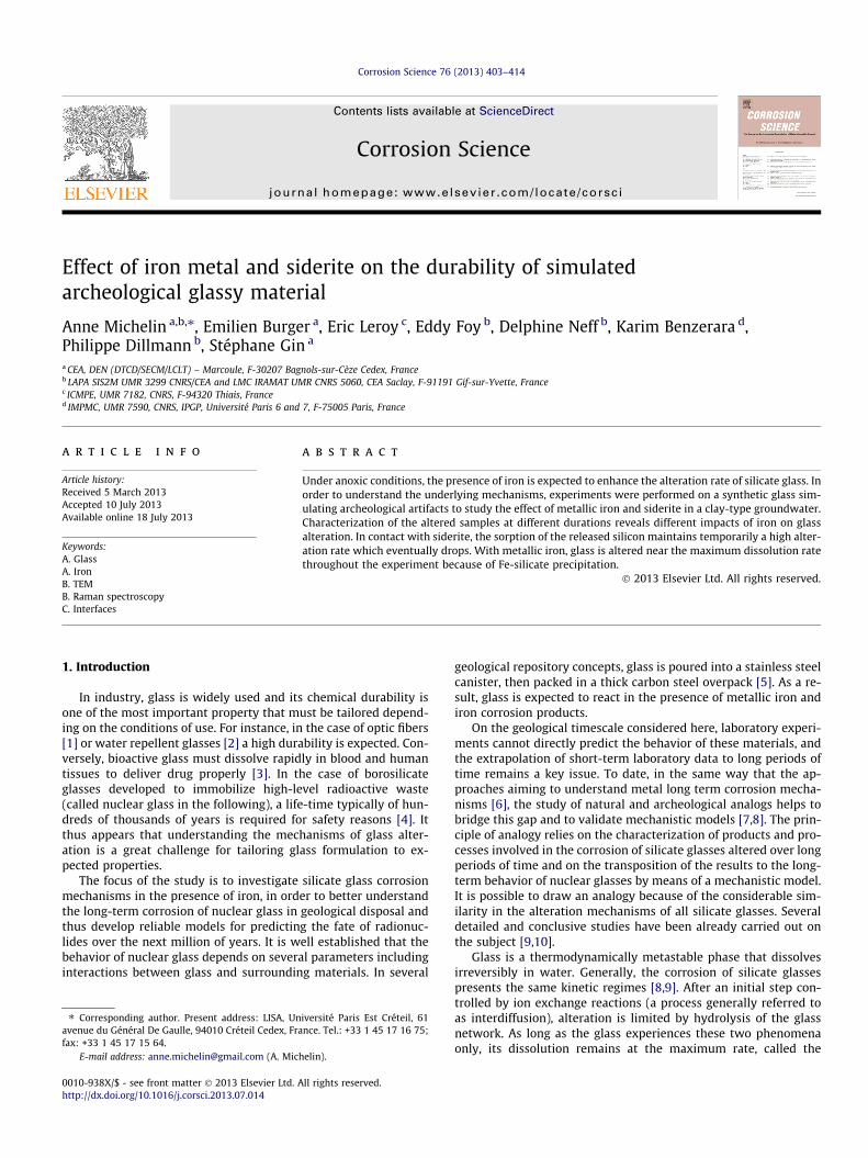
Finally, a third step was necessary to obtain phase separationobserved on archeological glass with size-controlled spheroids.For this purpose, a heat treatment was performed on the glass ata temperature below the critical temperature (here Tc = 1000 �C).At any given temperature below Tc, spheroids grow by Ostwald rip-ening following a coarsening law where the radius evolves withthe cube root of time. It was thus possible to plot a calibrationcurve in order to determine the proper duration of heat treatment.Several glass samples corresponding to different durations of heattreatment at 950 �C were characterized by FEG-SEM (field emissiongun scanning electron microscopy) to produce this curve. Based onthis calibration, a 1-h treatment was performed to obtain spher-oids measuring 285 nm in diameter (Fig. 1).
The composition of the synthetic glass, determined by ICP-AES(inductively coupled plasma atomic emission spectroscopy) afterdissolution of the glass in hydrofluoric acid, is indicated in Table 1.Given the variations in archeological glass compositions (Table 1,determined by EDS), the obtained composition is similar to the ref-erence glass.
2.2. Experimental setup
2.2.1. Leaching testsThe initial dissolution rate of the glass, r0, was measured at
30 �C and 50 �C by Soxhlet tests. The Soxhlet test (ISO16797:2004) consists in dissolving a glass specimen (powder ormonolith) in pure water frequently or continuously renewed. Asystem of evaporation (boiler) and condensation (condenser)makes it possible. The elements released by the glass are collectedin the boiler in which samples are regularly taken and analyzed. Inour case, the sample is placed in a PTFE vessel located in an ovenregulated at 30 ± 1 �C or 50 ± 1 �C.
A small (50 mL) PTFE reactor was chosen to contain the glasssample in order to insure a high water renewal rate leading to verydilute conditions near the glass surface. The advantage of this
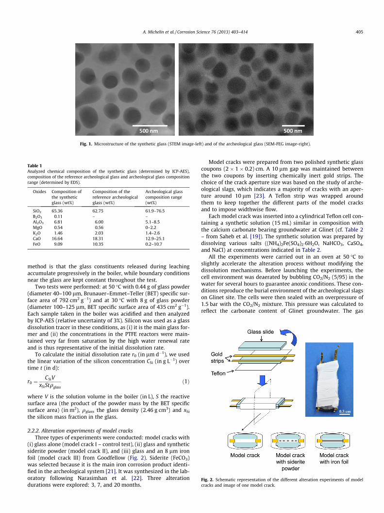
Fig. 1. Microstructure of the synthetic glass (STEM image-left) and of the archeological glass (SEM-FEG image-right).
Table 1Analyzed chemical composition of the synthetic glass (determined by ICP-AES),composition of the reference archeological glass and archeological glass compositionrange (determined by EDS).
Oxides Composition ofthe syntheticglass (wt%)
Composition of thereference archeologicalglass (wt%)
Archeological glasscomposition range(wt%)
SiO2 65.36 62.75 61.9–76.5B2O3 0.11 – –Al2O3 6.81 6.00 5.1–8.5MgO 0.54 0.56 0–2.2K2O 1.46 2.03 1.4–2.6CaO 16.64 18.31 12.9–25.1FeO 9.09 10.35 0.2–10.7
Fig. 2. Schematic representation of the different alteration experiments of modelcracks and image of one model crack.
A. Michelin et al. / Corrosion Science 76 (2013) 403–414 405
method is that the glass constituents released during leachingaccumulate progressively in the boiler, while boundary conditionsnear the glass are kept constant throughout the test.
Two tests were performed: at 50 �C with 0.44 g of glass powder(diameter 40–100 lm, Brunauer–Emmet–Teller (BET) specific sur-face area of 792 cm2 g�1) and at 30 �C with 8 g of glass powder(diameter 100–125 lm, BET specific surface area of 435 cm2 g�1).Each sample taken in the boiler was acidified and then analyzedby ICP-AES (relative uncertainty of 3%). Silicon was used as a glassdissolution tracer in these conditions, as (i) it is the main glass for-mer and (ii) the concentrations in the PTFE reactors were main-tained very far from saturation by the high water renewal rateand is thus representative of the initial dissolution rate.
To calculate the initial dissolution rate r0 (in lm d�1), we usedthe linear variation of the silicon concentration CSi (in g L�1) overtime t (in d):
r0 ¼CSiV
xSiStqglassð1Þ
where V is the solution volume in the boiler (in L), S the reactivesurface area (the product of the powder mass by the BET specificsurface area) (in m2), qglass the glass density (2.46 g cm3) and xSi
the silicon mass fraction in the glass.
2.2.2. Alteration experiments of model cracksThree types of experiments were conducted: model cracks with
(i) glass alone (model crack I – control test), (ii) glass and syntheticsiderite powder (model crack II), and (iii) glass and an 8 lm ironfoil (model crack III) from Goodfellow (Fig. 2). Siderite (FeCO3)was selected because it is the main iron corrosion product identi-fied in the archeological system [21]. It was synthesized in the lab-oratory following Narasimhan et al. [22]. Three alterationdurations were explored: 3, 7, and 20 months.
Model cracks were prepared from two polished synthetic glasscoupons (2 � 1 � 0.2) cm. A 10 lm gap was maintained betweenthe two coupons by inserting chemically inert gold strips. Thechoice of the crack aperture size was based on the study of arche-ological slags, which indicates a majority of cracks with an aper-ture around 10 lm [23]. A Teflon strip was wrapped aroundthem to keep together the different parts of the model cracksand to impose widthwise flow.
Each model crack was inserted into a cylindrical Teflon cell con-taining a synthetic solution (15 mL) similar in composition withthe calcium carbonate bearing groundwater at Glinet (cf. Table 2– from Saheb et al. [19]). The synthetic solution was prepared bydissolving various salts ((NH4)2Fe(SO4)2�6H2O, NaHCO3, CaSO4,and NaCl) at concentrations indicated in Table 2.
All the experiments were carried out in an oven at 50 �C toslightly accelerate the alteration process without modifying thedissolution mechanisms. Before launching the experiments, thecell environment was deaerated by bubbling CO2/N2 (5/95) in thewater for several hours to guarantee anoxic conditions. These con-ditions reproduce the burial environment of the archeological slagson Glinet site. The cells were then sealed with an overpressure of1.5 bar with the CO2/N2 mixture. This pressure was calculated toreflect the carbonate content of Glinet groundwater. The gas
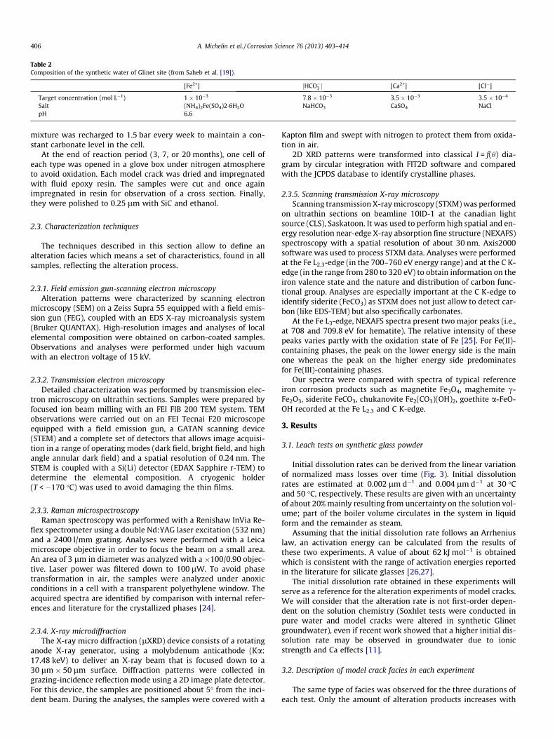
Table 2Composition of the synthetic water of Glinet site (from Saheb et al. [19]).
[Fe2+] ½HCO�3 � [Ca2+] [Cl�]
Target concentration (mol L�1) 1 � 10�3 7.8 � 10�3 3.5 � 10�3 3.5 � 10�4
Salt (NH4)2Fe(SO4)2�6H2O NaHCO3 CaSO4 NaClpH 6.6
406 A. Michelin et al. / Corrosion Science 76 (2013) 403–414
mixture was recharged to 1.5 bar every week to maintain a con-stant carbonate level in the cell.
At the end of reaction period (3, 7, or 20 months), one cell ofeach type was opened in a glove box under nitrogen atmosphereto avoid oxidation. Each model crack was dried and impregnatedwith fluid epoxy resin. The samples were cut and once againimpregnated in resin for observation of a cross section. Finally,they were polished to 0.25 lm with SiC and ethanol.
2.3. Characterization techniques
The techniques described in this section allow to define analteration facies which means a set of characteristics, found in allsamples, reflecting the alteration process.
2.3.1. Field emission gun-scanning electron microscopyAlteration patterns were characterized by scanning electron
microscopy (SEM) on a Zeiss Supra 55 equipped with a field emis-sion gun (FEG), coupled with an EDS X-ray microanalysis system(Bruker QUANTAX). High-resolution images and analyses of localelemental composition were obtained on carbon-coated samples.Observations and analyses were performed under high vacuumwith an electron voltage of 15 kV.
2.3.2. Transmission electron microscopyDetailed characterization was performed by transmission elec-
tron microscopy on ultrathin sections. Samples were prepared byfocused ion beam milling with an FEI FIB 200 TEM system. TEMobservations were carried out on an FEI Tecnai F20 microscopeequipped with a field emission gun, a GATAN scanning device(STEM) and a complete set of detectors that allows image acquisi-tion in a range of operating modes (dark field, bright field, and highangle annular dark field) and a spatial resolution of 0.24 nm. TheSTEM is coupled with a Si(Li) detector (EDAX Sapphire r-TEM) todetermine the elemental composition. A cryogenic holder(T < �170 �C) was used to avoid damaging the thin films.
2.3.3. Raman microspectroscopyRaman spectroscopy was performed with a Renishaw InVia Re-
flex spectrometer using a double Nd:YAG laser excitation (532 nm)and a 2400 l/mm grating. Analyses were performed with a Leicamicroscope objective in order to focus the beam on a small area.An area of 3 lm in diameter was analyzed with a �100/0.90 objec-tive. Laser power was filtered down to 100 lW. To avoid phasetransformation in air, the samples were analyzed under anoxicconditions in a cell with a transparent polyethylene window. Theacquired spectra are identified by comparison with internal refer-ences and literature for the crystallized phases [24].
2.3.4. X-ray microdiffractionThe X-ray micro diffraction (lXRD) device consists of a rotating
anode X-ray generator, using a molybdenum anticathode (Ka:17.48 keV) to deliver an X-ray beam that is focused down to a30 lm � 50 lm surface. Diffraction patterns were collected ingrazing-incidence reflection mode using a 2D image plate detector.For this device, the samples are positioned about 5� from the inci-dent beam. During the analyses, the samples were covered with a
Kapton film and swept with nitrogen to protect them from oxida-tion in air.
2D XRD patterns were transformed into classical I = f(h) dia-gram by circular integration with FIT2D software and comparedwith the JCPDS database to identify crystalline phases.
2.3.5. Scanning transmission X-ray microscopyScanning transmission X-ray microscopy (STXM) was performed
on ultrathin sections on beamline 10ID-1 at the canadian lightsource (CLS), Saskatoon. It was used to perform high spatial and en-ergy resolution near-edge X-ray absorption fine structure (NEXAFS)spectroscopy with a spatial resolution of about 30 nm. Axis2000software was used to process STXM data. Analyses were performedat the Fe L2,3-edge (in the 700–760 eV energy range) and at the C K-edge (in the range from 280 to 320 eV) to obtain information on theiron valence state and the nature and distribution of carbon func-tional group. Analyses are especially important at the C K-edge toidentify siderite (FeCO3) as STXM does not just allow to detect car-bon (like EDS-TEM) but also specifically carbonates.
At the Fe L3-edge, NEXAFS spectra present two major peaks (i.e.,at 708 and 709.8 eV for hematite). The relative intensity of thesepeaks varies partly with the oxidation state of Fe [25]. For Fe(II)-containing phases, the peak on the lower energy side is the mainone whereas the peak on the higher energy side predominatesfor Fe(III)-containing phases.
Our spectra were compared with spectra of typical referenceiron corrosion products such as magnetite Fe3O4, maghemite c-Fe2O3, siderite FeCO3, chukanovite Fe2(CO3)(OH)2, goethite a-FeO-OH recorded at the Fe L2,3 and C K-edge.
3. Results
3.1. Leach tests on synthetic glass powder
Initial dissolution rates can be derived from the linear variationof normalized mass losses over time (Fig. 3). Initial dissolutionrates are estimated at 0.002 lm d�1 and 0.004 lm d�1 at 30 �Cand 50 �C, respectively. These results are given with an uncertaintyof about 20% mainly resulting from uncertainty on the solution vol-ume; part of the boiler volume circulates in the system in liquidform and the remainder as steam.
Assuming that the initial dissolution rate follows an Arrheniuslaw, an activation energy can be calculated from the results ofthese two experiments. A value of about 62 kJ mol�1 is obtainedwhich is consistent with the range of activation energies reportedin the literature for silicate glasses [26,27].
The initial dissolution rate obtained in these experiments willserve as a reference for the alteration experiments of model cracks.We will consider that the alteration rate is not first-order depen-dent on the solution chemistry (Soxhlet tests were conducted inpure water and model cracks were altered in synthetic Glinetgroundwater), even if recent work showed that a higher initial dis-solution rate may be observed in groundwater due to ionicstrength and Ca effects [11].
3.2. Description of model crack facies in each experiment
The same type of facies was observed for the three durations ofeach test. Only the amount of alteration products increases with
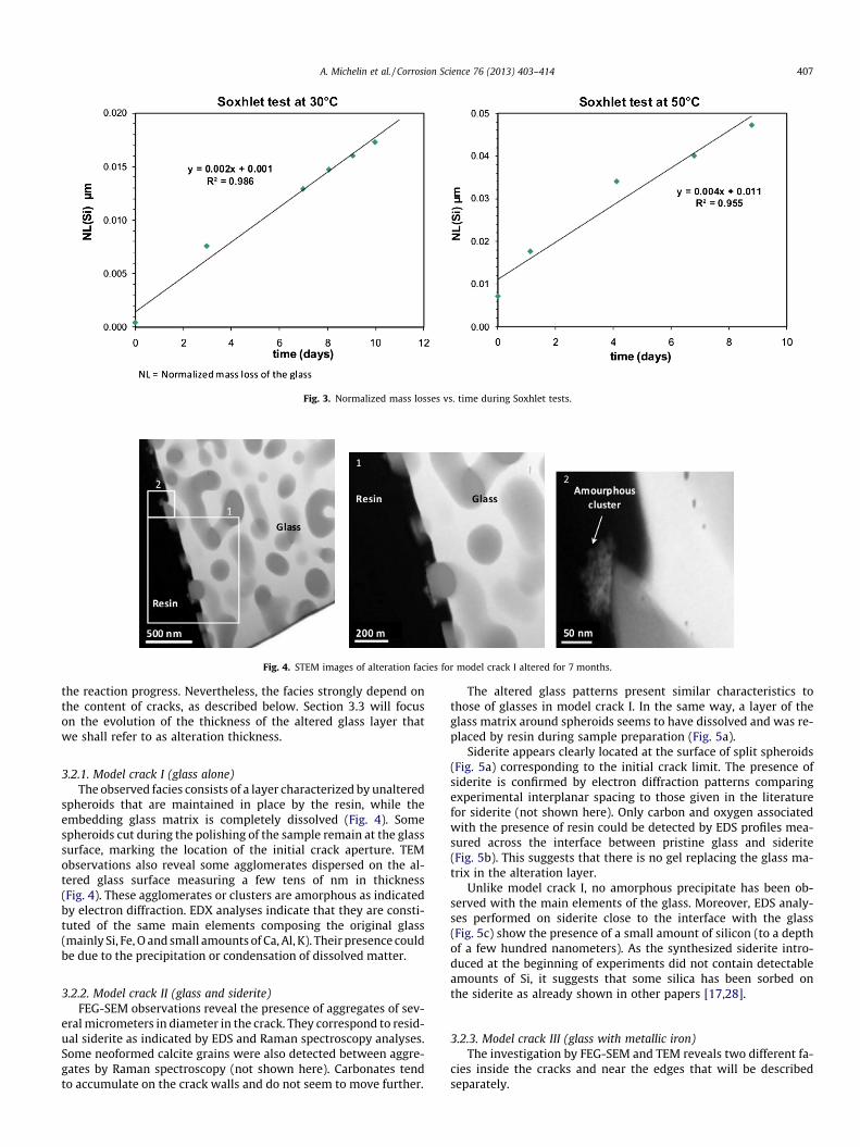
Fig. 3. Normalized mass losses vs. time during Soxhlet tests.
Fig. 4. STEM images of alteration facies for model crack I altered for 7 months.
A. Michelin et al. / Corrosion Science 76 (2013) 403–414 407
the reaction progress. Nevertheless, the facies strongly depend onthe content of cracks, as described below. Section 3.3 will focuson the evolution of the thickness of the altered glass layer thatwe shall refer to as alteration thickness.
3.2.1. Model crack I (glass alone)The observed facies consists of a layer characterized by unaltered
spheroids that are maintained in place by the resin, while theembedding glass matrix is completely dissolved (Fig. 4). Somespheroids cut during the polishing of the sample remain at the glasssurface, marking the location of the initial crack aperture. TEMobservations also reveal some agglomerates dispersed on the al-tered glass surface measuring a few tens of nm in thickness(Fig. 4). These agglomerates or clusters are amorphous as indicatedby electron diffraction. EDX analyses indicate that they are consti-tuted of the same main elements composing the original glass(mainly Si, Fe, O and small amounts of Ca, Al, K). Their presence couldbe due to the precipitation or condensation of dissolved matter.
3.2.2. Model crack II (glass and siderite)FEG-SEM observations reveal the presence of aggregates of sev-
eral micrometers in diameter in the crack. They correspond to resid-ual siderite as indicated by EDS and Raman spectroscopy analyses.Some neoformed calcite grains were also detected between aggre-gates by Raman spectroscopy (not shown here). Carbonates tendto accumulate on the crack walls and do not seem to move further.
The altered glass patterns present similar characteristics tothose of glasses in model crack I. In the same way, a layer of theglass matrix around spheroids seems to have dissolved and was re-placed by resin during sample preparation (Fig. 5a).
Siderite appears clearly located at the surface of split spheroids(Fig. 5a) corresponding to the initial crack limit. The presence ofsiderite is confirmed by electron diffraction patterns comparingexperimental interplanar spacing to those given in the literaturefor siderite (not shown here). Only carbon and oxygen associatedwith the presence of resin could be detected by EDS profiles mea-sured across the interface between pristine glass and siderite(Fig. 5b). This suggests that there is no gel replacing the glass ma-trix in the alteration layer.
Unlike model crack I, no amorphous precipitate has been ob-served with the main elements of the glass. Moreover, EDS analy-ses performed on siderite close to the interface with the glass(Fig. 5c) show the presence of a small amount of silicon (to a depthof a few hundred nanometers). As the synthesized siderite intro-duced at the beginning of experiments did not contain detectableamounts of Si, it suggests that some silica has been sorbed onthe siderite as already shown in other papers [17,28].
3.2.3. Model crack III (glass with metallic iron)The investigation by FEG-SEM and TEM reveals two different fa-
cies inside the cracks and near the edges that will be describedseparately.
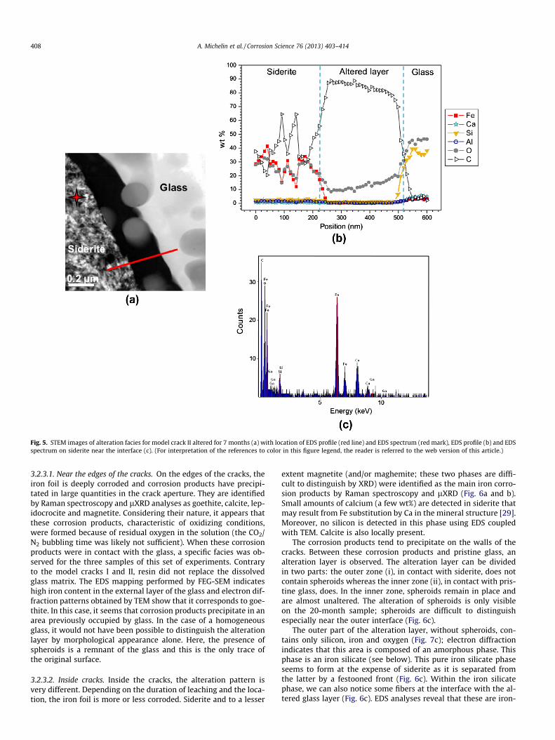
Fig. 5. STEM images of alteration facies for model crack II altered for 7 months (a) with location of EDS profile (red line) and EDS spectrum (red mark), EDS profile (b) and EDSspectrum on siderite near the interface (c). (For interpretation of the references to color in this figure legend, the reader is referred to the web version of this article.)
408 A. Michelin et al. / Corrosion Science 76 (2013) 403–414
3.2.3.1. Near the edges of the cracks. On the edges of the cracks, theiron foil is deeply corroded and corrosion products have precipi-tated in large quantities in the crack aperture. They are identifiedby Raman spectroscopy and lXRD analyses as goethite, calcite, lep-idocrocite and magnetite. Considering their nature, it appears thatthese corrosion products, characteristic of oxidizing conditions,were formed because of residual oxygen in the solution (the CO2/N2 bubbling time was likely not sufficient). When these corrosionproducts were in contact with the glass, a specific facies was ob-served for the three samples of this set of experiments. Contraryto the model cracks I and II, resin did not replace the dissolvedglass matrix. The EDS mapping performed by FEG-SEM indicateshigh iron content in the external layer of the glass and electron dif-fraction patterns obtained by TEM show that it corresponds to goe-thite. In this case, it seems that corrosion products precipitate in anarea previously occupied by glass. In the case of a homogeneousglass, it would not have been possible to distinguish the alterationlayer by morphological appearance alone. Here, the presence ofspheroids is a remnant of the glass and this is the only trace ofthe original surface.
3.2.3.2. Inside cracks. Inside the cracks, the alteration pattern isvery different. Depending on the duration of leaching and the loca-tion, the iron foil is more or less corroded. Siderite and to a lesser
extent magnetite (and/or maghemite; these two phases are diffi-cult to distinguish by XRD) were identified as the main iron corro-sion products by Raman spectroscopy and lXRD (Fig. 6a and b).Small amounts of calcium (a few wt%) are detected in siderite thatmay result from Fe substitution by Ca in the mineral structure [29].Moreover, no silicon is detected in this phase using EDS coupledwith TEM. Calcite is also locally present.
The corrosion products tend to precipitate on the walls of thecracks. Between these corrosion products and pristine glass, analteration layer is observed. The alteration layer can be dividedin two parts: the outer zone (i), in contact with siderite, does notcontain spheroids whereas the inner zone (ii), in contact with pris-tine glass, does. In the inner zone, spheroids remain in place andare almost unaltered. The alteration of spheroids is only visibleon the 20-month sample; spheroids are difficult to distinguishespecially near the outer interface (Fig. 6c).
The outer part of the alteration layer, without spheroids, con-tains only silicon, iron and oxygen (Fig. 7c); electron diffractionindicates that this area is composed of an amorphous phase. Thisphase is an iron silicate (see below). This pure iron silicate phaseseems to form at the expense of siderite as it is separated fromthe latter by a festooned front (Fig. 6c). Within the iron silicatephase, we can also notice some fibers at the interface with the al-tered glass layer (Fig. 6c). EDS analyses reveal that these are iron-
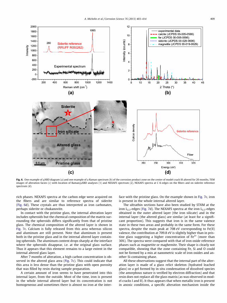
Fig. 6. One example of lXRD diagram (a) and one example of a Raman spectrum (b) of the corrosion product zone on the center of model crack III altered for 20 months, TEMimages of alteration facies (c) with location of Raman/lXRD analyses (1) and NEXAFS spectrum (2), NEXAFS spectra at C K-edges on the fibers and on siderite referencespectrum (d).
A. Michelin et al. / Corrosion Science 76 (2013) 403–414 409
rich phases. NEXAFS spectra at the carbon edge were acquired onthe fibers and are similar to reference spectra of siderite(Fig. 6d). These crystals are thus interpreted as iron carbonates,perhaps siderite or chukanovite.
In contact with the pristine glass, the internal alteration layerincludes spheroids but the chemical composition of the matrix sur-rounding the spheroids differs significantly from that of pristineglass. The chemical composition of the altered layer is shown inFig. 7c. Calcium is fully released from this area whereas siliconand aluminum are still present. Note that aluminum is presentboth in the pristine glass and in the internal altered layer contain-ing spheroids. The aluminum content drops sharply at the interfacewhere the spheroids disappear, i.e. at the original glass surface.Thus it appears that this element remains to a large extent in theinternal altered glass layer.
After 7 months of alteration, a high carbon concentration is ob-served in the altered glass area (Fig. 7c). This could indicate thatthis area is less dense than the pristine glass with open porositythat was filled by resin during sample preparation.
A certain amount of iron seems to have penetrated into thisinternal layer, from the outside. Most of the time, iron is presentin the whole internal altered layer but its concentration is nothomogeneous and sometimes there is almost no iron at the inter-
face with the pristine glass. On the example shown in Fig. 7c, ironis present in the whole internal altered layer.
The ultrathin sections have also been studied by STXM at theiron L2,3-edges (Fig. 7d). The NEXAFS spectra at the iron L2,3-edgesobtained in the outer altered layer (the iron silicate) and in theinternal layer (the altered glass) are similar (at least for a signifi-cant proportion). This suggests that iron is in the same valencestate in these two areas and probably in the same form. For thesespectra, despite the main peak at 708 eV corresponding to Fe(II)valence, the contribution at 709.8 eV is slightly higher than in pris-tine glass suggesting a higher concentration of Fe3+ (more than30%). The spectra were compared with that of iron oxide referencephases such as magnetite or maghemite. Their shape is clearly notcompatible, showing that the zone containing Fe, Si and O couldnot be formed by a mix at nanometric scale of iron oxides and an-other Si-containing phase.
All these observations suggest that the internal part of the alter-ation layer is made of a glass relict skeleton (hydrated leachedglass) or a gel formed by in situ condensation of dissolved species(the amorphous nature is verified by electron diffraction) and thatresin does not replace all the glass matrix (as was observed in mod-el cracks I and II). It thus appears that when metallic iron is presentin anoxic conditions, a specific alteration mechanism inside the
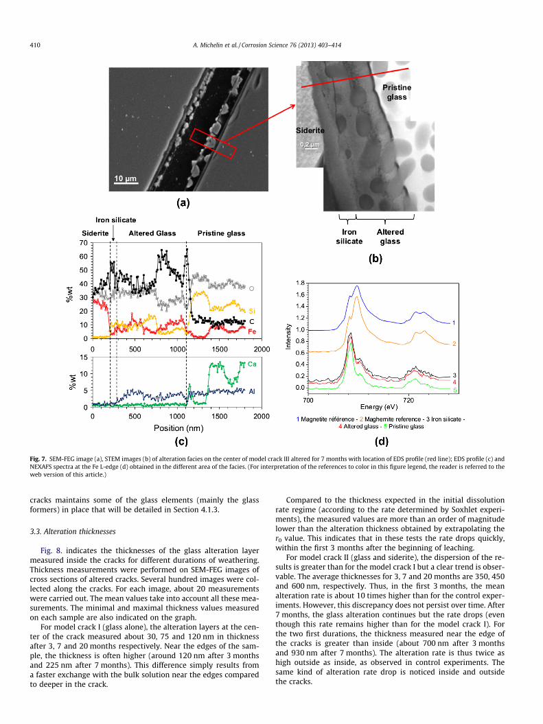
Fig. 7. SEM-FEG image (a), STEM images (b) of alteration facies on the center of model crack III altered for 7 months with location of EDS profile (red line); EDS profile (c) andNEXAFS spectra at the Fe L-edge (d) obtained in the different area of the facies. (For interpretation of the references to color in this figure legend, the reader is referred to theweb version of this article.)
410 A. Michelin et al. / Corrosion Science 76 (2013) 403–414
cracks maintains some of the glass elements (mainly the glassformers) in place that will be detailed in Section 4.1.3.
3.3. Alteration thicknesses
Fig. 8. indicates the thicknesses of the glass alteration layermeasured inside the cracks for different durations of weathering.Thickness measurements were performed on SEM-FEG images ofcross sections of altered cracks. Several hundred images were col-lected along the cracks. For each image, about 20 measurementswere carried out. The mean values take into account all these mea-surements. The minimal and maximal thickness values measuredon each sample are also indicated on the graph.
For model crack I (glass alone), the alteration layers at the cen-ter of the crack measured about 30, 75 and 120 nm in thicknessafter 3, 7 and 20 months respectively. Near the edges of the sam-ple, the thickness is often higher (around 120 nm after 3 monthsand 225 nm after 7 months). This difference simply results froma faster exchange with the bulk solution near the edges comparedto deeper in the crack.
Compared to the thickness expected in the initial dissolutionrate regime (according to the rate determined by Soxhlet experi-ments), the measured values are more than an order of magnitudelower than the alteration thickness obtained by extrapolating ther0 value. This indicates that in these tests the rate drops quickly,within the first 3 months after the beginning of leaching.
For model crack II (glass and siderite), the dispersion of the re-sults is greater than for the model crack I but a clear trend is obser-vable. The average thicknesses for 3, 7 and 20 months are 350, 450and 600 nm, respectively. Thus, in the first 3 months, the meanalteration rate is about 10 times higher than for the control exper-iments. However, this discrepancy does not persist over time. After7 months, the glass alteration continues but the rate drops (eventhough this rate remains higher than for the model crack I). Forthe two first durations, the thickness measured near the edge ofthe cracks is greater than inside (about 700 nm after 3 monthsand 930 nm after 7 months). The alteration rate is thus twice ashigh outside as inside, as observed in control experiments. Thesame kind of alteration rate drop is noticed inside and outsidethe cracks.
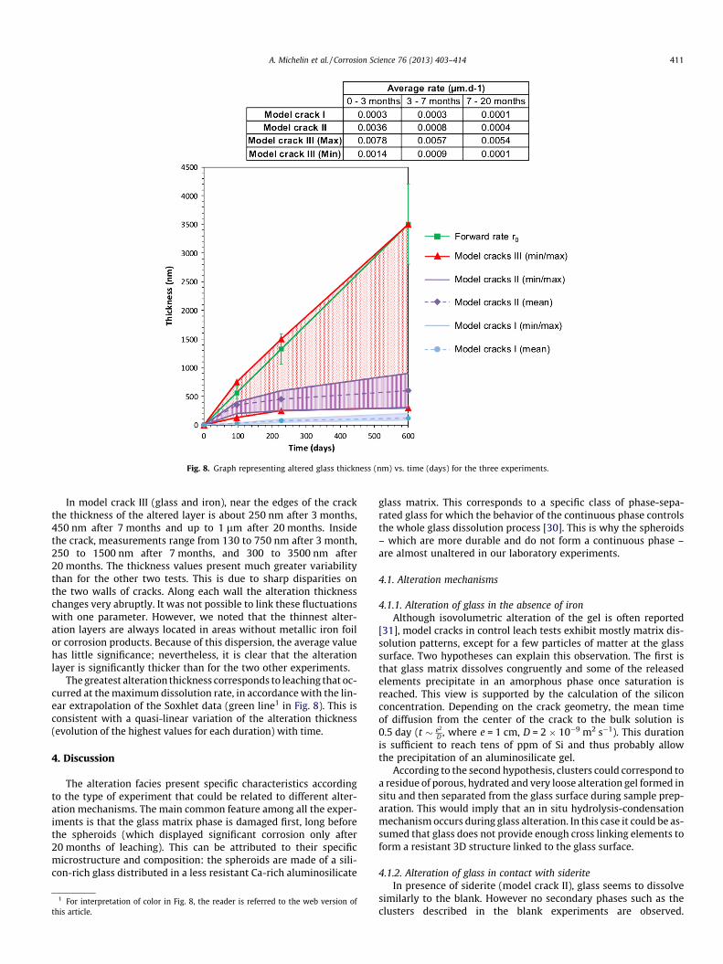
Fig. 8. Graph representing altered glass thickness (nm) vs. time (days) for the three experiments.
A. Michelin et al. / Corrosion Science 76 (2013) 403–414 411
In model crack III (glass and iron), near the edges of the crackthe thickness of the altered layer is about 250 nm after 3 months,450 nm after 7 months and up to 1 lm after 20 months. Insidethe crack, measurements range from 130 to 750 nm after 3 month,250 to 1500 nm after 7 months, and 300 to 3500 nm after20 months. The thickness values present much greater variabilitythan for the other two tests. This is due to sharp disparities onthe two walls of cracks. Along each wall the alteration thicknesschanges very abruptly. It was not possible to link these fluctuationswith one parameter. However, we noted that the thinnest alter-ation layers are always located in areas without metallic iron foilor corrosion products. Because of this dispersion, the average valuehas little significance; nevertheless, it is clear that the alterationlayer is significantly thicker than for the two other experiments.
The greatest alteration thickness corresponds to leaching that oc-curred at the maximum dissolution rate, in accordance with the lin-ear extrapolation of the Soxhlet data (green line1 in Fig. 8). This isconsistent with a quasi-linear variation of the alteration thickness(evolution of the highest values for each duration) with time.
4. Discussion
The alteration facies present specific characteristics accordingto the type of experiment that could be related to different alter-ation mechanisms. The main common feature among all the exper-iments is that the glass matrix phase is damaged first, long beforethe spheroids (which displayed significant corrosion only after20 months of leaching). This can be attributed to their specificmicrostructure and composition: the spheroids are made of a sili-con-rich glass distributed in a less resistant Ca-rich aluminosilicate
1 For interpretation of color in Fig. 8, the reader is referred to the web version ofthis article.
glass matrix. This corresponds to a specific class of phase-sepa-rated glass for which the behavior of the continuous phase controlsthe whole glass dissolution process [30]. This is why the spheroids– which are more durable and do not form a continuous phase –are almost unaltered in our laboratory experiments.
4.1. Alteration mechanisms
4.1.1. Alteration of glass in the absence of ironAlthough isovolumetric alteration of the gel is often reported
[31], model cracks in control leach tests exhibit mostly matrix dis-solution patterns, except for a few particles of matter at the glasssurface. Two hypotheses can explain this observation. The first isthat glass matrix dissolves congruently and some of the releasedelements precipitate in an amorphous phase once saturation isreached. This view is supported by the calculation of the siliconconcentration. Depending on the crack geometry, the mean timeof diffusion from the center of the crack to the bulk solution is0.5 day (t � e2
D , where e = 1 cm, D = 2 � 10�9 m2 s�1). This durationis sufficient to reach tens of ppm of Si and thus probably allowthe precipitation of an aluminosilicate gel.
According to the second hypothesis, clusters could correspond toa residue of porous, hydrated and very loose alteration gel formed insitu and then separated from the glass surface during sample prep-aration. This would imply that an in situ hydrolysis-condensationmechanism occurs during glass alteration. In this case it could be as-sumed that glass does not provide enough cross linking elements toform a resistant 3D structure linked to the glass surface.
4.1.2. Alteration of glass in contact with sideriteIn presence of siderite (model crack II), glass seems to dissolve
similarly to the blank. However no secondary phases such as theclusters described in the blank experiments are observed.
412 A. Michelin et al. / Corrosion Science 76 (2013) 403–414
EDS-TEM characterization suggests a new mechanism, as siliconhas been evidenced in siderite crystals near the glass surface. Thepresence of Si in siderite could be explained by sorption of this ele-ment at the surface of carbonate grains. Previous studies [32] havealready shown that several iron corrosion products including sider-ite have some ability to sorb silicon. The silicon sorption could pre-vent the formation of the fragile alteration gel observed in theblank experiments, or may delay the solution saturation prevent-ing the precipitation of secondary phases. This could explain whyno clusters are observed in these experiments. The presence of sid-erite significantly increases the glass alteration by factors 5–10compared to the control. Thus, hydrolysis seems to be enhancedby this phenomenon. The alteration rate will be discussed in detailbelow.
4.1.3. Alteration of glass in contact with metallic ironThe presence of metallic iron deeply modifies the alteration fa-
cies especially in the center of cracks. Inside model crack III, sam-ples exhibit a layer of siderite, then a layer of iron silicate, andfinally a layer of altered glass characterized by the retention of alu-minum and an enrichment of iron.
In this study, we consider that the phase containing iron, siliconand oxygen is an iron silicate and not a mixture of hydrous ferrousoxide and silica complexed or precipitated at its surface as it is of-ten described in literature [33,34]. Indeed, no heterogeneities hasbeen observed in this phase at the nanometer scale and the L2,3-edge NEXAFS spectra are not consistent with those of iron oxidereferences.
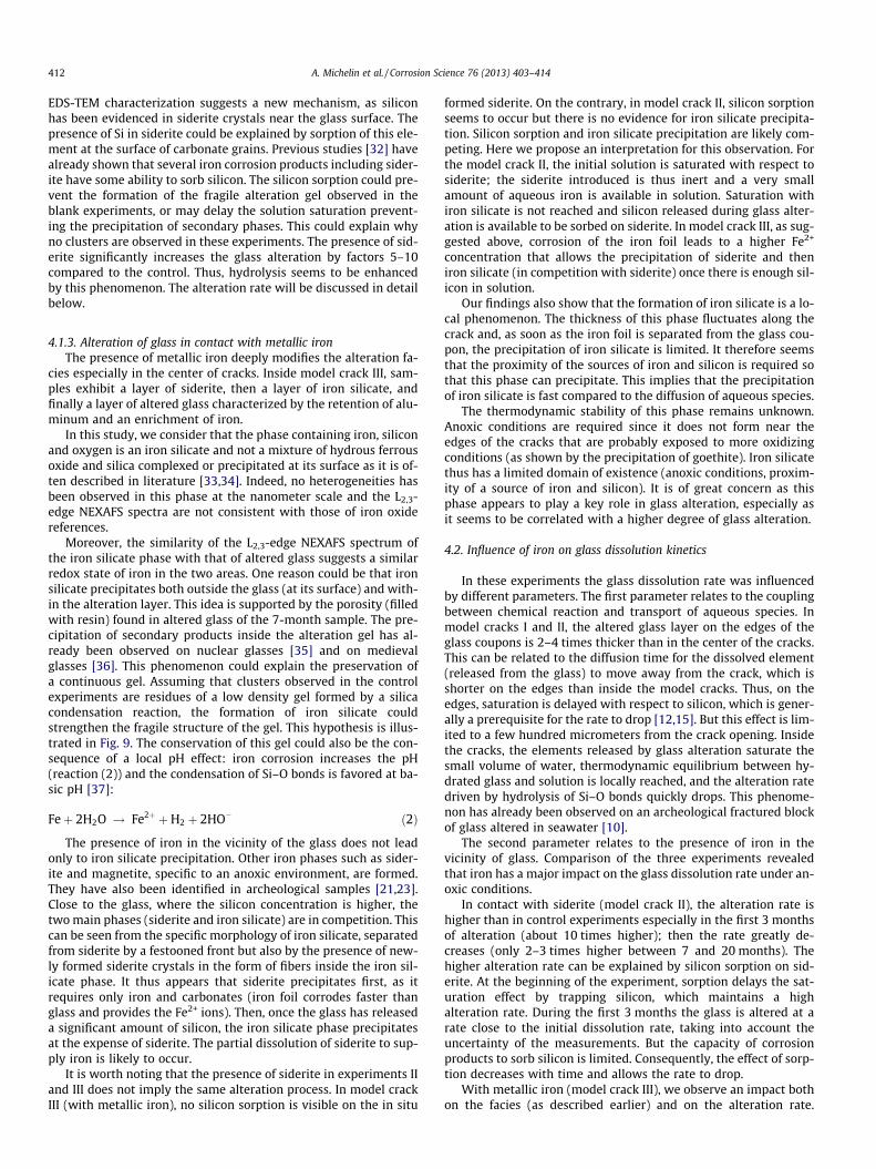
Moreover, the similarity of the L2,3-edge NEXAFS spectrum ofthe iron silicate phase with that of altered glass suggests a similarredox state of iron in the two areas. One reason could be that ironsilicate precipitates both outside the glass (at its surface) and with-in the alteration layer. This idea is supported by the porosity (filledwith resin) found in altered glass of the 7-month sample. The pre-cipitation of secondary products inside the alteration gel has al-ready been observed on nuclear glasses [35] and on medievalglasses [36]. This phenomenon could explain the preservation ofa continuous gel. Assuming that clusters observed in the controlexperiments are residues of a low density gel formed by a silicacondensation reaction, the formation of iron silicate couldstrengthen the fragile structure of the gel. This hypothesis is illus-trated in Fig. 9. The conservation of this gel could also be the con-sequence of a local pH effect: iron corrosion increases the pH(reaction (2)) and the condensation of Si–O bonds is favored at ba-sic pH [37]:
Feþ 2H2O ! Fe2þ þH2 þ 2HO� ð2Þ
The presence of iron in the vicinity of the glass does not leadonly to iron silicate precipitation. Other iron phases such as sider-ite and magnetite, specific to an anoxic environment, are formed.They have also been identified in archeological samples [21,23].Close to the glass, where the silicon concentration is higher, thetwo main phases (siderite and iron silicate) are in competition. Thiscan be seen from the specific morphology of iron silicate, separatedfrom siderite by a festooned front but also by the presence of new-ly formed siderite crystals in the form of fibers inside the iron sil-icate phase. It thus appears that siderite precipitates first, as itrequires only iron and carbonates (iron foil corrodes faster thanglass and provides the Fe2+ ions). Then, once the glass has releaseda significant amount of silicon, the iron silicate phase precipitatesat the expense of siderite. The partial dissolution of siderite to sup-ply iron is likely to occur.
It is worth noting that the presence of siderite in experiments IIand III does not imply the same alteration process. In model crackIII (with metallic iron), no silicon sorption is visible on the in situ
formed siderite. On the contrary, in model crack II, silicon sorptionseems to occur but there is no evidence for iron silicate precipita-tion. Silicon sorption and iron silicate precipitation are likely com-peting. Here we propose an interpretation for this observation. Forthe model crack II, the initial solution is saturated with respect tosiderite; the siderite introduced is thus inert and a very smallamount of aqueous iron is available in solution. Saturation withiron silicate is not reached and silicon released during glass alter-ation is available to be sorbed on siderite. In model crack III, as sug-gested above, corrosion of the iron foil leads to a higher Fe2+
concentration that allows the precipitation of siderite and theniron silicate (in competition with siderite) once there is enough sil-icon in solution.
Our findings also show that the formation of iron silicate is a lo-cal phenomenon. The thickness of this phase fluctuates along thecrack and, as soon as the iron foil is separated from the glass cou-pon, the precipitation of iron silicate is limited. It therefore seemsthat the proximity of the sources of iron and silicon is required sothat this phase can precipitate. This implies that the precipitationof iron silicate is fast compared to the diffusion of aqueous species.
The thermodynamic stability of this phase remains unknown.Anoxic conditions are required since it does not form near theedges of the cracks that are probably exposed to more oxidizingconditions (as shown by the precipitation of goethite). Iron silicatethus has a limited domain of existence (anoxic conditions, proxim-ity of a source of iron and silicon). It is of great concern as thisphase appears to play a key role in glass alteration, especially asit seems to be correlated with a higher degree of glass alteration.
4.2. Influence of iron on glass dissolution kinetics
In these experiments the glass dissolution rate was influencedby different parameters. The first parameter relates to the couplingbetween chemical reaction and transport of aqueous species. Inmodel cracks I and II, the altered glass layer on the edges of theglass coupons is 2–4 times thicker than in the center of the cracks.This can be related to the diffusion time for the dissolved element(released from the glass) to move away from the crack, which isshorter on the edges than inside the model cracks. Thus, on theedges, saturation is delayed with respect to silicon, which is gener-ally a prerequisite for the rate to drop [12,15]. But this effect is lim-ited to a few hundred micrometers from the crack opening. Insidethe cracks, the elements released by glass alteration saturate thesmall volume of water, thermodynamic equilibrium between hy-drated glass and solution is locally reached, and the alteration ratedriven by hydrolysis of Si–O bonds quickly drops. This phenome-non has already been observed on an archeological fractured blockof glass altered in seawater [10].
The second parameter relates to the presence of iron in thevicinity of glass. Comparison of the three experiments revealedthat iron has a major impact on the glass dissolution rate under an-oxic conditions.
In contact with siderite (model crack II), the alteration rate ishigher than in control experiments especially in the first 3 monthsof alteration (about 10 times higher); then the rate greatly de-creases (only 2–3 times higher between 7 and 20 months). Thehigher alteration rate can be explained by silicon sorption on sid-erite. At the beginning of the experiment, sorption delays the sat-uration effect by trapping silicon, which maintains a highalteration rate. During the first 3 months the glass is altered at arate close to the initial dissolution rate, taking into account theuncertainty of the measurements. But the capacity of corrosionproducts to sorb silicon is limited. Consequently, the effect of sorp-tion decreases with time and allows the rate to drop.
With metallic iron (model crack III), we observe an impact bothon the facies (as described earlier) and on the alteration rate.
Fig. 9. Diagram of the evolution of the gel layer in the different experiments leading to the formation of the observed alteration facies.
A. Michelin et al. / Corrosion Science 76 (2013) 403–414 413
Globally, the alteration layer is thicker than in the other experi-ments even if the data are more scattered. For all the durations,the greatest measured thicknesses correspond to alteration at themaximum rate (initial dissolution rate). In this study, model cracksIII are the only ones where a gel is formed. As the altered glasslayer is thicker, it seems that this gel has no protective properties– as it has been demonstrated for nuclear glasses under conditionsof low Si concentration in solution [38].
In these experiments, the increased alteration rate appears to becorrelated with the formation of iron silicate. On the crack edges,where there is no iron silicate, the alteration layer is thinner thanin the center of the cracks. This iron silicate could play the samerole as some secondary phases such as zeolites. Two different ef-fects related to the presence of secondary phases have been re-ported in the literature. Zeolites affect the protective propertiesof the existing alteration gel because they are formed at its ex-pense, and are responsible for a resumption of alteration [39].The second phenomenon has been observed for Mg–silicate[40,41]. Whatever the source of Mg (from the solution or fromthe glass), its formation requires silicon and its consumption en-hances hydrolysis of the glassy network by delaying the saturationof the solution. This could explain why such a high alteration rateis maintained throughout the experiment.
This dispersion of thickness values reflects the local nature ofthe influence of iron. The formation of iron silicate has a great im-pact on the alteration rate but it requires conditions that are notmet in the entire crack. Since there are sudden variations, theseconditions appear to be highly specific.
5. Conclusion
These laboratory experiments demonstrate that iron has a con-siderable influence on both the alteration facies and alteration ratefor this phase-separated glass. Two mechanisms are involveddepending on the manner in which iron is introduced. Silicon sorp-tion occurs in contact with siderite, leading to higher alterationrates, but this effect has a limited impact. When metallic iron ispresent, an iron silicate phase precipitates both outside and inside
the altered glass layer. The aluminosilicate gel is thus consolidatedand can be maintained in place unlike the other types of experi-ments. The iron silicate phase seems to play the role of a siliconpump and has a significant effect on the alteration kinetics. Alter-ation can be maintained almost at the initial dissolution rate, butthis effect is local. The formation of iron silicate depends on severalparameters such as anoxic conditions and high iron and siliconconcentrations.
In these short-term experiments, the second mechanism ap-pears to be decisive with regard to the alteration rate, and wecan wonder what the consequences might be on long-term behav-ior. Future characterizations of Glinet slags will help answering.The same issues can be considered for nuclear glass alteration, asthis phase could maintain high dissolution rates.
Acknowledgments
This work is part of the Glass/Iron/Clay Laboratory Group pro-gram of the French National Radioactive Waste ManagementAgency (ANDRA) which partly funded it. The authors would liketo thank the staff of beamline 10ID-1 at CLS for their assistanceduring STXM experiments. The authors are grateful to Alain Watti-aux (ICMCB) for Mössbauer analysis and Mathieu Pinault (SPAM,CEA) for access to SEM-FEG. They also thank the archaeologistDanielle Arribet-Deroin for providing access to the archaeologicalsite of Glinet.
References
[1] Y.-F. Niu, J.-P. Guin, T. Rouxel, A. Abdelouas, J. Troles, F. Smektala, Aqueouscorrosion of the GeSe4 chalcogenide glass: surface properties and corrosionmechanism, J. Am. Ceram. Soc. 92 (2009) 1779–1787.
[2] T. Yoneda, T. Morimoto, Mechanical durability of water repellent glass, ThinSolid Films. 351 (1999) 279–283.
[3] X. Liu, Z. Xie, C. Zhang, H. Pan, M.N. Rahaman, X. Zhang, Q. Fu, W. Huang,Bioactive borate glass scaffolds: in vitro and in vivo evaluation for use as a drugdelivery system in the treatment of bone infection, J. Mater. Sci.: Mater. Med.21 (2010) 575–582.
[4] B. Grambow, Nuclear waste glasses – how durable?, Elements 2 (2006) 357–364
414 A. Michelin et al. / Corrosion Science 76 (2013) 403–414
[5] ANDRA, Dossier 2005 Argile: synthesis – evaluation of the feasibility of ageological repository in an argillaceous formation, collection les rapports,ANDRA (agence nationale pour la gestion des déchets radioactifs), Chatenay-Malabry, France, 2005, 239 p.
[6] D. Neff, M. Saheb, J. Monnier, S. Perrin, M. Descostes, V. L’Hostis, D. Crusset, A.Millard, P. Dillmann, A review of the archaeological analogue approaches topredict the longterm corrosion behaviour of carbon steel overpack andreinforced concrete structures in the French disposal systems, J. Nucl. Mater.402 (2010) 196–205.
[7] R.C. Ewing, Natural glasses and the ‘‘verification’’ of the long-term durability ofnuclear waste glasses: the role of natural analogues, Méjannes-Le-Clap-FRANCE. CEA/VALRHO, 1997, pp. 589–600.
[8] G. Libourel, A. Verney-Carron, A. Morlok, S. Gin, J. Sterpenich, A. Michelin, D.Neff, P. Dillmann, The use of natural and archeological analogues forunderstanding the long-term behavior of nuclear glasses, CR Geosci. 343(2011) 237–245.
[9] I. Techer, T. Advocat, J. Lancelot, J.M. Liotard, Basaltic glass: alterationmechanisms and analogy with nuclear waste glasses, J. Nucl. Mater. 282(2000) 40–46.
[10] A. Verney-Carron, S. Gin, G. Libourel, A fractured roman glass block altered for1800 years in seawater: analogy with nuclear waste glass in a deep geologicalrepository, Geochim. Cosmochim. Acta 72 (2008) (1800) 5372–5385.
[11] P. Jollivet, S. Gin, S. Schumacher, Forward dissolution rate of silicate glasses ofnuclear interest in clay-equilibrated groundwater, Chem. Geol. 330–331(2012) 207–217.
[12] B. Grambow, A general rate equation for nuclear waste glass corrosion, Mater.Res. Soc. Symp. Proc. 44 (1985) 15–27.
[13] P. Van Iseghem, K. Berghman, K. Lemmens, W. Timmermans, L. Wang,Laboratory and in situ interaction between simulated waste glasses and clay– task 3: characterization of radioactive waste forms – a series of final reports,1985–1989. No. 21. Rapport interne: European Commission EUR 13607 EN,1992, 127 p.
[14] C. Cailleteau, F. Angeli, F. Devreux, S. Gin, J. Jestin, P. Jollivet, O. Spalla, Insightinto silicate-glass corrosion mechanisms, Nat. Mater. 7 (2008) 978–983.
[15] P. Frugier, S. Gin, Y. Minet, T. Chave, B. Bonin, N. Godon, J.-E. Lartigue, P.Jollivet, A. Ayral, L. De Windt, G. Santarini, SON68 nuclear glass dissolutionkinetics: current state of knowledge and basis of the new graal model, J. Nucl.Mater. 380 (2008) 8–21.
[16] G.L. McVay, C.Q. Buckwalter, Effect of iron on waste–glass leaching, J. Am.Ceram. Soc. 66 (1983) 170–177.
[17] B. Grambow, H.U. Zwicky, G. Bart, I.K. Björner, L.O. Werme, Modeling the effectof iron corrosion products on nuclear glass performance, Mat. Res. Soc. Symp.Proc. 84 (1987) 471–481.
[18] G. De Combarieu, M.L. Schlegel, D. Neff, E. Foy, D. Vantelon, P. Barboux, S. Gin,Glass–iron–clay interactions in a radioactive waste geological disposal: anintegrated laboratory-scale experiment, Appl. Geochem. 26 (2011) 65–79.
[19] M. Saheb, M. Descostes, D. Neff, H. Matthiesen, A. Michelin, P. Dillmann, Ironcorrosion in anoxic media: confrontation between ferrous archaeologicalartefacts and geochemical modeling, Appl. Geochem. 25 (2010) 1937–1948.
[20] A. Michelin, E. Burger, D. Rebiscoul, D. Neff, F. Bruguier, E. Drouet, P. Dillmann,S. Gin, Silicate glass alteration enhanced by iron: origin and long-termimplications, Environ. Sci. Technol. 47 (2013) 750–756.
[21] M. Saheb, D. Neff, C. Bataillon, E. Foy, P. Dillmann, Copper tracing to determinethe micrometric electronic properties of a thick ferrous corrosion layer formedin an anoxic medium, Corros. Sci. 53 (2011) 2201–2207.
[22] B.R.V. Narasimhan, S. Prabhakar, P. Manohar, F.D. Gnanam, Synthesis ofgamma ferric oxide by direct thermal decomposition of ferrous carbonate,Mater. Lett. 52 (2002) 295–300.
[23] A. Michelin, Altération pluriséculaire des systèmes verre/fer en milieuanoxique: apport des analogues archéologiques à la compréhension desmécanismes, in: Ph.D. thesis, Université Pierre et Marie Curie, Paris, France,2011.
[24] D. Neff, P. Dillmann, L. Bellot-Gurlet, G. Béranger, Corrosion of ironarchaeological artefacts in soil: characterisation of the corrosion system,Corros. Sci. 47 (2005) 515–535.
[25] P.A. Van Aken, B. Liebscher, Quantification of ferrous/ferric ratios in minerals:New evaluation schemes of Fe L2,3 electron energy-loss near-edge spectra,Phys. Chem. Miner. 29 (2002) 188–200.
[26] J.L. Crovisier, B. Fritz, B. Grambow, J.P. Eberhart, Dissolution of basaltic glass inseawater: experiments and thermodynamic modeling, Mater. Res. Soc. Symp.Proc. 50 (1985) 273–280.
[27] C. Guy, J. Schott, Multisite surface reaction vs. transport control during thehydrolysis of a complex oxide, Chem. Geol. 78 (1989) 181–204.
[28] G. Bart, H.U. Zwicky, E.T. Aerne, T.H. Graber, D.Z. Berg, M. Tokiwai, Borosilicateglass corrosion in the presence of steel corrosion products, Mat. Res. Soc.Symp. Proc. 84 (1987) 459–470.
[29] L.L.Y. Chang, R.A. Howie, J. Zussman, Rock-forming minerals, Non-silicates:sulphates, carbonates, phosphates, halides, vol. 5B, second ed., Longman GroupLimited, Essex, England, 1996, 383 p.
[30] O.V. Mazurin, E.A. Porai-Koshits, Phase separation in glass, North-HollandPhysics Publishing, Amsterdam, 1984. 369 p.
[31] N. Donzel, S. Gin, F. Augereau, M. Ramonda, Study of gel development duringSON68 glass alteration using atomic force microscopy. Comparison with twosimplified glasses, J. Nucl. Mater. 317 (2003) 83–92.
[32] V. Philippini, A. Naveau, H. Catalette, S. Leclercq, Sorption of silicon on magnetiteand other corrosion products of iron, J. Nucl. Mater. 348 (2006) 60–69.
[33] J.-P. Jolivet, E. Tronc, C. Chanéac, Iron oxides: From molecular clusters to solid.A nice example of chemical versatility, C.R. Geosci. 338 (2006) 488–497.
[34] C. Cismasu, M. Michel, P. Tcaciuc, T. Tyliszczak Jr., G.E. Brown, Composition andstructural aspects of naturally occurring ferrihydrite, C.R. Geosci. 343 (2011)210–218.
[35] J. Caurel, E. Vernaz, D. Beaufort, Hydrothermal leaching of R7T7 borosilicateglass, Mater. Res. Soc. Symp. Proc. 176 (1990) 309–318.
[36] T. Lombardo, L. Gentaz, A. Verney-Carron, A. Chabas, D. Neff, E. Leroy,Characterisation of complex alteration layers in medieval glasses, Corros. Sci.72 (2013) 10–19.
[37] J.-P. Jolivet, M. Henry, J. Livage, De la solution à l’oxyde, CNRS ed., InterEditions, Paris, 1994. 387 p.
[38] S. Gin, I. Ribet, M. Couillaud, Role and properties of the gel formed duringnuclear glass alteration: importance of gel formation conditions, J. Nucl. Mater.298 (2001) 1–10.
[39] S. Ribet, S. Gin, Role of neoformed phases on the mechanisms controlling theresumption of SON68 glass alteration in alkaline media, J. Nucl. Mater. 324(2004) 152–164.
[40] E. Curti, J.L. Crovisier, G. Morvan, A.M. Karpoff, Long-term corrosion of twonuclear waste reference glasses, MW and SON 68: a kinetic and mineralalteration study, Appl. Geochem. 21 (2006) 1152–1168.
[41] B. Thien, N. Godon, A. Ballestro, S. Gin, A. Ayral, The dual effect of Mg on thelong-term alteration rate of AVM nuclear waste glasses, J. Nucl. Mater. 427(2012) 297–310.
Related Documents